US9056396B1 - Programming of a robotic arm using a motion capture system - Google Patents
Programming of a robotic arm using a motion capture systemDownload PDFInfo
- Publication number
- US9056396B1 US9056396B1US14/195,412US201414195412AUS9056396B1US 9056396 B1US9056396 B1US 9056396B1US 201414195412 AUS201414195412 AUS 201414195412AUS 9056396 B1US9056396 B1US 9056396B1
- Authority
- US
- United States
- Prior art keywords
- tool
- robot
- control
- demonstration
- motion
- Prior art date
- Legal status (The legal status is an assumption and is not a legal conclusion. Google has not performed a legal analysis and makes no representation as to the accuracy of the status listed.)
- Active
Links
- 230000033001locomotionEffects0.000titleclaimsabstractdescription286
- 238000000034methodMethods0.000claimsabstractdescription65
- 230000010076replicationEffects0.000claimsabstractdescription47
- 230000006870functionEffects0.000claimsdescription38
- 230000000007visual effectEffects0.000claimsdescription19
- 238000004088simulationMethods0.000claimsdescription14
- 238000004519manufacturing processMethods0.000claimsdescription11
- 230000005484gravityEffects0.000claimsdescription2
- 238000004891communicationMethods0.000description11
- 230000000694effectsEffects0.000description11
- 230000009471actionEffects0.000description10
- 230000008569processEffects0.000description9
- 238000012552reviewMethods0.000description9
- 210000000707wristAnatomy0.000description9
- 238000010586diagramMethods0.000description8
- 238000003860storageMethods0.000description8
- 238000004458analytical methodMethods0.000description7
- 230000001133accelerationEffects0.000description6
- 239000012636effectorSubstances0.000description6
- 239000003292glueSubstances0.000description6
- 230000005540biological transmissionEffects0.000description5
- 238000012986modificationMethods0.000description5
- 230000004048modificationEffects0.000description5
- 230000008859changeEffects0.000description4
- 238000012545processingMethods0.000description4
- 238000003466weldingMethods0.000description4
- RTZKZFJDLAIYFH-UHFFFAOYSA-NDiethyl etherChemical compoundCCOCCRTZKZFJDLAIYFH-UHFFFAOYSA-N0.000description3
- 238000004364calculation methodMethods0.000description3
- 238000013461designMethods0.000description3
- 230000010354integrationEffects0.000description3
- 238000013507mappingMethods0.000description3
- 239000003550markerSubstances0.000description3
- 230000004044responseEffects0.000description3
- 230000002441reversible effectEffects0.000description3
- 238000012546transferMethods0.000description3
- 241000870659Crassula perfoliata var. minorSpecies0.000description2
- XEEYBQQBJWHFJM-UHFFFAOYSA-NIronChemical compound[Fe]XEEYBQQBJWHFJM-UHFFFAOYSA-N0.000description2
- 238000013459approachMethods0.000description2
- 230000008901benefitEffects0.000description2
- 230000003111delayed effectEffects0.000description2
- 230000000994depressogenic effectEffects0.000description2
- 238000001514detection methodMethods0.000description2
- 230000008571general functionEffects0.000description2
- 238000009499grossingMethods0.000description2
- 238000005259measurementMethods0.000description2
- 230000006855networkingEffects0.000description2
- 230000003287optical effectEffects0.000description2
- 239000013308plastic optical fiberSubstances0.000description2
- 238000003825pressingMethods0.000description2
- 230000003362replicative effectEffects0.000description2
- 238000005201scrubbingMethods0.000description2
- 230000003068static effectEffects0.000description2
- 230000009466transformationEffects0.000description2
- 238000000844transformationMethods0.000description2
- 238000013519translationMethods0.000description2
- 230000014616translationEffects0.000description2
- RYGMFSIKBFXOCR-UHFFFAOYSA-NCopperChemical compound[Cu]RYGMFSIKBFXOCR-UHFFFAOYSA-N0.000description1
- 238000004026adhesive bondingMethods0.000description1
- 230000006399behaviorEffects0.000description1
- 230000001413cellular effectEffects0.000description1
- 238000012790confirmationMethods0.000description1
- 230000036461convulsionEffects0.000description1
- 229910052802copperInorganic materials0.000description1
- 239000010949copperSubstances0.000description1
- 230000001934delayEffects0.000description1
- 238000012217deletionMethods0.000description1
- 230000037430deletionEffects0.000description1
- 238000006073displacement reactionMethods0.000description1
- 150000002170ethersChemical class0.000description1
- 238000002474experimental methodMethods0.000description1
- 239000000284extractSubstances0.000description1
- 230000001815facial effectEffects0.000description1
- 239000000835fiberSubstances0.000description1
- 230000003116impacting effectEffects0.000description1
- 230000003993interactionEffects0.000description1
- 229910052742ironInorganic materials0.000description1
- 230000007774longtermEffects0.000description1
- 239000000463materialSubstances0.000description1
- 230000005055memory storageEffects0.000description1
- 239000002184metalSubstances0.000description1
- 229910052751metalInorganic materials0.000description1
- 239000000203mixtureSubstances0.000description1
- 230000002093peripheral effectEffects0.000description1
- 230000002085persistent effectEffects0.000description1
- 238000000053physical methodMethods0.000description1
- 230000000644propagated effectEffects0.000description1
- 238000007670refiningMethods0.000description1
- 230000011514reflexEffects0.000description1
- 230000006903response to temperatureEffects0.000description1
- 238000005070samplingMethods0.000description1
- 238000001356surgical procedureMethods0.000description1
- 230000001360synchronised effectEffects0.000description1
- 230000002123temporal effectEffects0.000description1
- 238000012360testing methodMethods0.000description1
Images


Classifications
- B—PERFORMING OPERATIONS; TRANSPORTING
- B25—HAND TOOLS; PORTABLE POWER-DRIVEN TOOLS; MANIPULATORS
- B25J—MANIPULATORS; CHAMBERS PROVIDED WITH MANIPULATION DEVICES
- B25J9/00—Programme-controlled manipulators
- B25J9/16—Programme controls
- B25J9/1694—Programme controls characterised by use of sensors other than normal servo-feedback from position, speed or acceleration sensors, perception control, multi-sensor controlled systems, sensor fusion
- B25J9/1697—Vision controlled systems
- G—PHYSICS
- G05—CONTROLLING; REGULATING
- G05B—CONTROL OR REGULATING SYSTEMS IN GENERAL; FUNCTIONAL ELEMENTS OF SUCH SYSTEMS; MONITORING OR TESTING ARRANGEMENTS FOR SUCH SYSTEMS OR ELEMENTS
- G05B19/00—Programme-control systems
- G05B19/02—Programme-control systems electric
- G05B19/42—Recording and playback systems, i.e. in which the programme is recorded from a cycle of operations, e.g. the cycle of operations being manually controlled, after which this record is played back on the same machine
- G05B19/427—Teaching successive positions by tracking the position of a joystick or handle to control the positioning servo of the tool head, leader-follower control
- B—PERFORMING OPERATIONS; TRANSPORTING
- B25—HAND TOOLS; PORTABLE POWER-DRIVEN TOOLS; MANIPULATORS
- B25J—MANIPULATORS; CHAMBERS PROVIDED WITH MANIPULATION DEVICES
- B25J9/00—Programme-controlled manipulators
- B25J9/16—Programme controls
- B25J9/1656—Programme controls characterised by programming, planning systems for manipulators
- B25J9/1664—Programme controls characterised by programming, planning systems for manipulators characterised by motion, path, trajectory planning
- G—PHYSICS
- G05—CONTROLLING; REGULATING
- G05B—CONTROL OR REGULATING SYSTEMS IN GENERAL; FUNCTIONAL ELEMENTS OF SUCH SYSTEMS; MONITORING OR TESTING ARRANGEMENTS FOR SUCH SYSTEMS OR ELEMENTS
- G05B2219/00—Program-control systems
- G05B2219/30—Nc systems
- G05B2219/36—Nc in input of data, input key till input tape
- G05B2219/36442—Automatically teaching, teach by showing
- G—PHYSICS
- G05—CONTROLLING; REGULATING
- G05B—CONTROL OR REGULATING SYSTEMS IN GENERAL; FUNCTIONAL ELEMENTS OF SUCH SYSTEMS; MONITORING OR TESTING ARRANGEMENTS FOR SUCH SYSTEMS OR ELEMENTS
- G05B2219/00—Program-control systems
- G05B2219/30—Nc systems
- G05B2219/37—Measurements
- G05B2219/37563—Ccd, tv camera
- Y—GENERAL TAGGING OF NEW TECHNOLOGICAL DEVELOPMENTS; GENERAL TAGGING OF CROSS-SECTIONAL TECHNOLOGIES SPANNING OVER SEVERAL SECTIONS OF THE IPC; TECHNICAL SUBJECTS COVERED BY FORMER USPC CROSS-REFERENCE ART COLLECTIONS [XRACs] AND DIGESTS
- Y10—TECHNICAL SUBJECTS COVERED BY FORMER USPC
- Y10S—TECHNICAL SUBJECTS COVERED BY FORMER USPC CROSS-REFERENCE ART COLLECTIONS [XRACs] AND DIGESTS
- Y10S901/00—Robots
- Y10S901/01—Mobile robot
- Y—GENERAL TAGGING OF NEW TECHNOLOGICAL DEVELOPMENTS; GENERAL TAGGING OF CROSS-SECTIONAL TECHNOLOGIES SPANNING OVER SEVERAL SECTIONS OF THE IPC; TECHNICAL SUBJECTS COVERED BY FORMER USPC CROSS-REFERENCE ART COLLECTIONS [XRACs] AND DIGESTS
- Y10—TECHNICAL SUBJECTS COVERED BY FORMER USPC
- Y10S—TECHNICAL SUBJECTS COVERED BY FORMER USPC CROSS-REFERENCE ART COLLECTIONS [XRACs] AND DIGESTS
- Y10S901/00—Robots
- Y10S901/46—Sensing device
- Y10S901/47—Optical
Definitions
- Motion controlis a type of automation, where the position of an object or objects is controlled using some type of device such as a robotic arm.
- some type of devicesuch as a robotic arm.
- motion controlis used when a camera is mounted and controlled as part of the creation and recording of a video scene. This technique is commonly referred to as motion control photography.
- the present disclosureprovides methods and apparatuses that allow for capturing motions of a demonstration tool and using the captured motions to cause a robotic device to replicate motions of the demonstration tool with a robot tool.
- a motion capture systemmay use one or more cameras to capture positions of the demonstration tool over time (e.g., as a user demonstrates some type of activity).
- a motion path for a robot toole.g., an end-effector-mounted tool on the robotic device
- the robotic devicemay then be controlled to move its robot tool along the motion path to replicate the motions of the demonstration tool.
- a methodin one example, includes receiving data from one or more cameras indicative of position of a demonstration tool. Based on the received data, the method may further include determining a motion path of the demonstration tool, where the motion path includes a sequence of positions of the demonstration tool. The method may also include determining a replication control path for a robotic device, where the replication control path includes one or more robot movements that cause the robotic device to move a robot tool through a motion path that corresponds to the motion path of the demonstration tool. The method may further include causing the robotic device to move the robot tool using the one or more robot movements within the replication control path.
- a systemincluding a demonstration tool, a robotic device, at least one camera, and a control system.
- the control systemmay be configured to receive data from the at least one camera indicative of position of the demonstration tool. Based on the received data, the control system may further be configured to determine a motion path of the demonstration tool, where the motion path includes a sequence of positions of the demonstration tool.
- the control systemmay also be configured to determine a replication control path for the robotic device, where the replication control path includes one or more robot movements that cause the robotic device to move a robot tool through a motion path that corresponds to the motion path of the demonstration tool.
- the control systemmay additionally be configured to cause the robotic device to move the robot tool using the one or more robot movements within the replication control path.
- a non-transitory computer readable medium having stored therein instructions, that when executed by a computing system, cause the computing system to perform functionsis disclosed.
- the functionsmay include receiving data from one or more cameras indicative of position of a demonstration tool. Based on the received data, the functions may further include determining a motion path of the demonstration tool, where the motion path includes a sequence of positions of the demonstration tool.
- the functionsmay also include determining a replication control path for a robotic device, where the replication control path includes one or more robot movements that cause the robotic device to move a robot tool through a motion path that corresponds to the motion path of the demonstration tool.
- the functionsmay further include causing the robotic device to move the robot tool using the one or more robot movements within the replication control path.
- a systemmay include means for receiving information reports relating to driving conditions from a plurality of autonomous vehicles within a fleet of autonomous vehicles.
- the systemmay also include means for receiving data from one or more cameras indicative of position of a demonstration tool. Based on the received data, the system may further include means for determining a motion path of the demonstration tool, where the motion path includes a sequence of positions of the demonstration tool.
- the systemmay also include means for determining a replication control path for a robotic device, where the replication control path includes one or more robot movements that cause the robotic device to move a robot tool through a motion path that corresponds to the motion path of the demonstration tool.
- the systemmay further include means for causing the robotic device to move the robot tool using the one or more robot movements within the replication control path.
- FIG. 1shows a block diagram of a motion control photography system including a master scene control, according to an example embodiment.
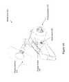
- FIG. 2shows a perspective view of a robot for use with a motion control photography system, according to an example embodiment.
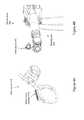
- FIG. 3Ashows a view of a robot with 7 degrees of freedom, according to an example embodiment.
- FIG. 3Bshows a view of a robot with an attached camera, according to an example embodiment.
- FIG. 3Cshows a view of a robot with an attached lighting unit, according to an example embodiment.
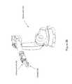
- FIG. 4Ashows a view of wrist mount for use with a robotic arm, according to an example embodiment.
- FIG. 4Bshows a view of a robot with an attached wrist mount, according to an example embodiment.
- FIG. 5Ashows one potential embodiment of a master input for use with a motion control system, according to an example embodiment.
- FIG. 5Billustrates a global timeline coordinating device actor positions through a master control, according to an example embodiment.
- FIG. 6shows a block diagram of a motion control photography system including a master scene control, according to an example embodiment.
- FIG. 7shows one potential implementation of a computer or electronic device, according to an example embodiment.
- FIG. 8illustrates a potential user interface for a software control, according to an example embodiment.
- FIG. 10illustrates a method of control, according to an example embodiment.
- FIG. 11is a block diagram of a method, according to an example embodiment.
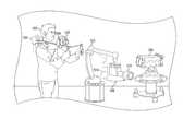
- FIG. 12Aillustrates a motion capture system and a human actor with a demonstration tool, according to an example embodiment.
- FIG. 12Billustrates a motion path of a demonstration tool, according to an example embodiment.
- FIG. 12Cillustrates a motion path of a demonstration tool and a corresponding motion path of a robot tool, according to an example embodiment.
- FIG. 12Dillustrates a motion path of a robot tool, according to an example embodiment.
- Example embodimentsmay include or otherwise relate to a motion-capture system that may be used to record positions of a moving demonstration tool, and then use the recorded positions to program a robotic device.
- a motion-capture systemmay use one or more optical sensors to determine a motion path followed by the demonstration tool.
- the motion path of the demonstration toolmay indicate the position of the tool (e.g., translation and orientation) over a series of timesteps.
- a motion path for a separate robot toole.g., an end-effector-mounted tool on a robotic device
- the robotic devicemay then be controlled in order to move its robot tool through the sequence of positions within the derived motion path.
- a robotic devicemay be trained to move a tool in much the same manner as a human demonstrator.
- Such a systemmay be useful for a wide variety of applications, and may be particularly useful in applications where it may be difficult to program a robot to move in the same nuanced manner as a human.
- applicationsmay exist in cinema (e.g., to control a camera), manufacturing (e.g., to control a welding tool), and/or design (e.g., to control a paint brush), among other possibilities.
- one or more camerasmay be directed toward an actor as the actor demonstrates how to use the tool.
- precise motion capturemay be achieved by attaching control markers onto the demonstration tool at one or more points.
- the control markersmay be passive markers (e.g., colored points detectable by a camera when lighted) or active markers which generate their own signal (e.g., light emitting diodes).
- some or all of the control markersmay have one or more distinguishing characteristics that can be distinguished by a camera in order to determine which points on the demonstration tool are moving. A combination of different types of markers may also be used.
- a user of the demonstration toolmay be shown a display with a visual simulation of how the motion of the tool will be replicated by a robotic device.
- the visual simulationmay show a virtual robot actor that simulates robot movements that will be followed by the robotic device to use a robot tool based on the demonstration.
- the visual simulationmay also show one or more visual curves and/or numerical values corresponding to motion characteristics of the robotic device (e.g., joint angles, velocities, and/or accelerations). By watching the visual simulation, the user may be able to adjust movements of the demonstration tool on the fly to better train the robotic device.
- the demonstration toolmay contain a button which controls when movements of the demonstration tool are recorded by the motion capture system.
- a warning signalmay be provided to the user when the demonstrated movements are approaching or have exceeded one or more predefined constraints of the robotic device. Accordingly, the user may be able to adjust movements of the demonstration tool in order to stay within the feasible range of motion of the robotic device.
- the display for the visual simulationmay be attached to or included within the demonstration tool (e.g., when the demonstration tool is a camera, a sub-window of a viewing screen of the camera may show the visual simulation).
- a replication control path consisting of robot movements of the robotic devicemay be determined that cause the robotic device to move the robot tool through captured positions of the demonstration tool. For instance, a sequence of joint angles of one or more joints of the robot may be determined that cause the robot to position an end-effector-mounted robot tool over a timeline. In some examples, a mapping between motion parameters of the robot (including joint angles, joint velocities, and/or joint accelerations) and corresponding positions of the robot tool may be determined in order to enable the robot to move an end-effector-mounted tool through a motion path that corresponds to the motion path of the demonstration tool. In further examples, the control path may sometimes be refined before it is used by the robotic device to replicate the movements of the demonstration tool.
- motion curves within the control pathmay be smoothed (e.g., to avoid jerking movements by the robot).
- a visual simulatione.g., animation of projected robot movements
- multiple review and replication phasesmay be used in order to iteratively improve the motion paths of the robotic actor. Through an iterative cycle, a robotic actor may be quickly trained to perform complicated motion paths. In other examples, separate review and replication phases may not exist. For instance, a robotic device may be controlled to use a robot tool in much the same way that a human demonstrator uses a demonstration tool in real time or approximately real time. Real time control may be useful in situations where the robotic device is operating in an area that is unsafe for a human, for example.
- the robotic devicemay then be used to replicate the motion of the demonstration tool with its own robot tool.
- the robotic activitymay then be repeated many times (e.g., a robot trained to use a glue gun with the deft of a skilled human actor may be used to repeat the process hundreds or thousands of times in manufacturing).
- positions of the robot toolmay also be captured using motion capture (e.g., using LED tags and a camera). These positions may be used to verify and/or refine the control path of the robot by comparing the actual resulting positions of the robot tool to the previously recorded positions of the demonstration tool. Multiple iterations of this process may also be used to further refine the robot control path as well
- the demonstration toolmay be controlled by forces of nature instead of or in addition to a human demonstrator.
- a ball with LED tagsmay be dropped and allowed to bounce as positions of the ball are captured by a camera.
- a robotmay then instructed to control a robot tool (e.g., a ball held by an end-effector of the robot) through a series of movements that replicate the bouncing ball. Accordingly, a control path of robot movements that simulate an object's changing position resulting from physical forces may be determined which may result in a more accurate simulation than trying to directly program the robot movements.
- Example embodimentsmay involve use of a robotic control system to create automated programming of robotics arms using motion control.
- FIG. 1describes an example motion control system 100 .
- Motion control system 100is part of a motion controlled set used to film a scene using motion control photography.
- Motion control system 100comprises a master control 10 , input and feedback systems 20 , device actors 40 , and safety systems 90 . From the most basic perspective, motion control system 100 functions when an input system 20 provides instructions to a device actor 40 via master control 10 .
- a scenecomprises a set of motions and actions by device actors 40 over a continuous period of time, such that a set of players in front of a camera is recorded in video, sound, or both.
- the playersare people, stationary objects, or objects controlled or moved by one or more devices of device actors 40 .
- the camerais mounted to a robot arm of device actors 40 .
- Motion control of device actors 40moves the camera and the players through a sequence of motions to the end of a scene, with players and sound from the scene recorded using the camera and potentially other audio and video recording equipment to capture the motion.
- input and feedback systems 20include a database 22 , a master input 24 , a software control 26 , and an independent manual control 28 .
- database 22operates to provide a set of timing and position data to direct all or a portion of device actors 40 .
- database 22stores data being created by manual or individual movement or data input related to operation and function of device actors 40 .
- Database 22also stores data created independently of device actors 40 , such as data created using software modeling features of a software control 26 .
- a master input 24is any device that functions to operate all of the device actors 40 associated with a particular scene being created with motion control system 100 .
- Master input 24functions by sending input control signals to master control 10 .
- Master control 10then adapts the signal from master input 24 to send individual control signals to a plurality of actors operating as device actors 40 for the particular scene.
- every individual device of device actors 40is provided a control signal from master control 10 when a signal is received from master input 24 , including a signal to maintain a status quo or non-action to devices that are not operating as device actors 40 for a particular scene.
- a portion of the device actors connected as part of motion control system 100are not sent any signal from master control 10 as part of the operation of motion control system 100 for a particular scene.
- Software control 26acts as a replacement for master input 24 in sending control signals to the plurality of actors via the master control 10 .
- software control 26controls individual devices from among device actors 40 to alternate, change, or experiment with motions of the individual device.
- software control 26functions to model the behavior of individual devices of device actors 40 within a virtual environment.
- software control 26contains a software model for an individual device, which allows control signals to be created for the device without actually sending the control signals to the device.
- the control signalsare then be stored in the software control 26 , in database 22 , within a computer memory component that is part of master control 10 , or within computer memory that is part of the device of device actors 40 for which the controls are being created.
- a master control signal from software control 26 or from master input 24activates the control signal for the individual device to act in conjunction with other device actors 40 .
- Certain devices of device actors 40additionally have an independent manual control 28 .
- control signals for an individual deviceare created in software modeling.
- a devicemay have independent manual control 28 that is used to operate a device of device actors 40 .
- a device that is one of device actors 40is a follow focus that controls the focus of a camera.
- the follow focusmay have a control device that is designed to control the focus of the camera that may operate as an independent manual control.
- the independent manual control 28is given input commands over time that are recorded to database 22 or a memory device of master control 10 .
- the independent manual control 28may communicate directly with the associated device of device actors 40 .
- the independent manual control 28may send the control signal to master control 10 , which then conveys the signal to the associated device of device actors 40 .
- the control signalmay then be created either from the signal of the independent manual control 28 , of from a measured feedback reading created by the operation of the associated device.
- control signalsis created without controlling the device. For example, if expected input signals are expected for certain time marks, an independent manual control 28 is operated independent of the related device, and the control operation recorded.
- FIG. 5Bprovides an illustrated example, where the actions of multiple motion controlled actors are integrated into a global timeline using a master control.
- various actorssuch as camera and lighting robots move at certain points during a scene.
- the actorsmay receive control signals during the entire scene from time a to time or may only receive controls when they actually move or act.
- Certain other actors, such as 1 st and 2 nd special effects (fx) actorsonly receive single commands to act at one specific time, such as 1 st fx actor acting at time b in the global timeline of FIG. 5B .
- Such an integration into a global timelineallows simplified user control of complex actions impacting an entire scene that may save significant amounts of time in modifying a particular scene with a given timeline. This allows scrubbing through time forward and backwards as well as seeking to specific frame number or timecode for all actors in a particular scene, and slowing down or speeding up the performance of the entire set (system) in real time via a hardware device.
- enhanced controlmay comprise systems and methods for a variety of functions, including safety systems, playback speed control, forward and reverse position scrubbing, and integrated detection systems, among others.
- Such a systemincludes advantages over systems currently known in the art by providing accessible and highly sophisticated robotic controls in an art environment dominated by custom toolsets without simple or malleable integration toolsets.
- Such a use of highly accurate control systems with camerasis considered, in certain embodiments, to be “cinematic automation” or “3D projection automation” which allows the ambitions of visual story tellers to be matched through the application of automation systems.
- improved control systemscan coordinate sub-millimeter position of a camera in space with the position of the light, an actress, a robotic actor comprising a 3D projection surface, and special effects (pyrotechnics, video playback, sound cues, etc.). This allows execution of highly complex shots that would previously have required the coordination of several film departments with manual human positioning.
- embodiments of the present innovationsinclude interfaces that allow a creative director to make very quick on-set adjustments.
- a director or visual effects supervisoris able to make very quick creative or technical calls, and the systems described herein enable this in a way not known in the previous art.
- the systemmight be synchronizing a large robotic arm, a custom robotic rig to move the arm, video playback of a wall of LED's that serve as the light source, and the motion of a piece of background, and an animatronic actor with facial features animated from a projector attached to an animation computer with arm and leg movement animated by robotics.
- Thisis a highly technical, pre-programmed scene that has been pre-visualized in a computer, and the interplay of all the elements have been choreographed using the system.
- a play directormay compensate real time by pausing the entire set or by simply turning a knob at the right moment to accommodate the actors.
- the robotslows down, the robotic rig complies, and the entire scene of the play decelerates. All of this happens in synchronicity. Plus the system can provide integrated enhanced safety to prevent the actors from being injured.
- FIGS. 2-4several non-limiting examples of device actors 40 will be described. Although these figures focus on the use of robotic arms, device actors is other types of devices that is stationary, such as sensors, stationary lights, and signal sources, as will be described later.
- FIG. 2describes device actor 242 .
- Device actor 242comprises robotic arm 246 , mounting point 248 , and rail 244 .
- Device actor 242is described in FIG. 2 with no specific functionality attached at any mounting point such as mounting point 248 .
- Mounting point 248is configured to hold a camera, a light, a player that will be filmed by a camera, or any other relevant device or object.
- instructionsis given to position mounting point 248 at a specific location, and the positions of the axis of robotic arm 246 and of rail 244 is calculated by a process of the related motion control system.
- each axis of robotic arm 246 and the position of rail 244require separate, individual settings and control commands.
- FIG. 3Adescribes device actor 342 , comprising a robotic arm with axis A1-A6, with axis A0 associated with a rail which is not shown that allows side to side movement of the other eight axes.
- FIG. 3Bdescribes device actor 342 with a camera mount 352 placed at a mounting point, and camera 350 attached to camera mount 352 .
- FIG. 3Cdescribes device actor 342 with light 360 placed at a mounting point.
- FIGS. 4A and 4Bdescribe an embodiment where a device actor 442 comprises a robotic arm 444 with a wrist mount 410 and a wrist mount interface 412 .
- Wrist mount 410 and wrist mount interface 412enables multiple device actors to be mounted to robotic arm 444 in addition to standard mounts such as a camera or lighting fixture.
- the wrist mount interfaceenables temperature sensors, laser range detectors, microphones, speakers, fans, or other mechanical activated or special effects devices.
- FIG. 5Adescribes master input 524 which is one potential implementation of a master input such as master input 24 of FIG. 1 .
- Master input 524comprises a display interface 510 , and engage control 540 , a mode select 530 , and an analog interface 520 .
- the function of master input 524will be described in conjunction with the global timeline of FIG. 5B .
- FIG. 5Billustrates a global timeline associated with one potential embodiment of a motion controlled scene implemented in a motion control system such as motion control system 100 of FIG. 1 .
- FIG. 5Bincludes a number of actors, as defined above, which operate during a scene with a nominal or standard running time from time a to time f.
- the global timelineis nominal and not referring to real clock time because, as will be detailed further below, master input controls alters the rate at which actors progress through motions from the beginning of a scene to the end of a scene.
- the global timelinemay therefore alternately be thought of as a coordinated position chart for actors.
- an actormay act or move during the entire scene, during a portion of the scene, or only for one instant of a scene.
- Each actor, though,will have a predetermined point for each nominal time from the beginning to the end of the scene.
- the predetermined points for each actorare associated with predetermined points for each other actor.
- individual control signals for specific device actorsare coordinated into a single file within a memory of a master control with a common base time provided by a master clock within the master control.
- master controlextracts control signals for each device actor and provides individual control signals to each device actor at the appropriate intervals.
- a master controlmaintains separate individual control signal files and timing data for different device actors, and synchronizes the different control signals separately from the individual control files.
- control data for a portion of the device actorsis transferred by a master control to a memory within an associated individual device actor.
- device actors having control data within memoryreceive only a synchronization signal that indicates a location in a global timeline, a rate of progress through a global timeline, or both.
- the specific embodiment described in FIG. 5Bincludes a camera robot, a follow focus, two lighting robots, a player robot that controls an object that is to appear in front of a camera, and two special effects actors.
- each actorhas a path to follow through the scene from beginning at time a to end at time f.
- each actorbegins at a preset position. As described by the global timeline, only the player robot moves from time a to time b. This will be true whether b occurs 10 seconds after starting time a, or 20 seconds after time a due to modification of the rate at which the scene progresses by a master input, as is further detailed below.
- 1 st special effects actoris activated with a single command, player robot continues moving, and follow focus and camera robot begin moving.
- FIG. 5Bmerely illustrates a global position timeline. In certain embodiments they may not be receiving input commands from a master control. In alternative embodiments, however, non-moving actors such as 1 st lighting robot may periodically or continuously receive commands from a master control, even when not moving, where the command is an instruction not to move. Such a command may function to maintain synchronization, acting as a clock or a timing heartbeat to maintain synchronization. In some embodiments, real time adjustments are made to an actor during a scene. Such a clock or timing heartbeat further serves to provide synchronization data as the adjustments feed back to the master control to update and change the global timeline.
- master input 524includes a display interface 510 .
- Display interface 510is a modular touch screen device that displays status information related to actors or the global timeline.
- display interface 510includes a scene time associated with the current position of the actors in the global timeline, or a frame number for a current scene associated with the current timeline. In such a display, time a, for example, or frame 1, is displayed when the actors are in position for the beginning of the scene.
- display interface 510is a portable electronic device or a cellular telephone with an interface application that communicates with a master control.
- Master input 524additionally comprises an engage control 540 . Because of the size and force that many actors, particularly large industrial robot arms carrying heavy cameras moving at up to several meters per second, are capable of conveying in a collision, safety controls is extremely important for many embodiments of a motion controlled scene.
- Engage control 540acts as an input regulator to prevent master input 524 from being operated by accident, such that engage control must be depressed at all times prior to any other input command being conveyed and acted upon from master input 524 .
- master input 524also comprises a mode select 530 and an analog interface 520 .
- Analog interface 520is any input device capable of defining a range of inputs by a user control.
- analog interface 520is a wheel with a spring action that returns the wheel to a central position in the absence of user manipulation.
- analog interfaceis a lever, a sliding tab, or any other input control to enable a user to input a signal.
- Master input 524may comprise multiple input modes.
- master input 524comprise a reset mode, a play mode, and a scan mode, with the mode selectable via mode select 530 .
- a reset modeoperation of engage control 540 and analog interface 520 operates to cause each actor within a scene to move to an initial position for the beginning of a global timeline. Additionally, a specific scene or frame number is selected by use of display interface 510 , and operation causes each actor to move to a position associated with that frame or time in the global timeline. Such a mode may allow device actors that are out of position for a particular time to be reset to a correct position.
- operation of analog interface 520may serve to speed up or slow down progress through a scene in a global timeline. For example, in a scene with actors set in position at global time a, selecting engage control 540 may serve to begin the action of all actors through the global timeline at a base rate, where each second of time is associated with one second of progress through the global timeline. Operation of analog interface 520 in a first direction then serves to slow down progress through the global timeline, such that 1 second of real time is associated with 0.5 seconds of progress through the global timeline. If the analog interface 520 is then set back to center, the progress through the global timeline will revert to a one to one ration with real time, but with the remaining actions being delayed from the initial start by the previous slowdown.
- analog interface 520is operated in a second direction opposite from the first direction, progress through the global timeline is increased. If, for example, the nominal time from time a to time b is 10 seconds, increasing progress through the global timeline by 10% may reduce that actual time required for the motion controlled scene to progress from the positions of time a to the positions of time b by approximately 0.9 seconds and the actual time required the progress from time a to time b with analog interface set to increase playback being approximately 9.1 seconds. This may provide use when a human player being recorded by a camera as part of a motion controlled scene is delivering lines more slowly or more quickly than expected, and there is a desire to match the actions of the motion controlled scenes with the actions of human players that are not motion controlled.
- selecting the engage control 540 and then operating analog interface 520may operate to shuttle or scan forwards or backwards through the global timeline in a continuous fashion. For example, if a motion controlled set currently has actors in positions associated with time c, selecting shuttle mode and operating analog interface 520 in a first direction may cause all actors to move continuously forward through the positions associated with the global timeline to reach time d. Moving analog interface 520 in a second direction may cause all actors to move continuously backwards through the positions associated with the global timeline to reach the positions associated with time b. In one potential embodiment, a particular time or frame is selected using display interface 510 . Operation of analog interface 520 may shuttle continuously through the positions of the global timeline until the particular time or frame is reached. Master input 524 may then cease to control device actors until a selection in display interface 510 is activated acknowledging that the previously selected point has been reached, or until analog interface 520 is returned to a central position.
- FIG. 6describes a block diagram of a motion control system 600 .
- Motion control system 600comprises a master control 610 , as well as details of one potential embodiment of input, feedback, and device actor sub-systems.
- master control 610comprises an operating system 614 , master control logic 612 , master clock 616 , network support 618 , control logic 696 , and feedback 698 .
- the elements of master control 610are implemented in a computer system comprising a general function processor and memory hardware system.
- master control 610is implemented in custom designed processing, memory, and networking hardware devices, or is implemented in an abstracted software layer of a general purpose computing system.
- Master clock 616functions as a real time clock to coordinate movement of the actors in the system.
- Master control logic 612functions to integrate the individual control signals into a master timeline, and to correctly route control signals to the correct device, both during operation of the entire motion control scene through the master timeline, and through individual modification and setting of device actor positioning and function using control logic 696 . Master control logic 612 also assists in coordination and routing of feedback 698 .
- Feedback 698may include actual position and setting signals received from monitors attached to device actors.
- One potential exampleis a location device attached to a robot arm. The actual position of the arm is tracked via the location device to provide feedback and calibration in relation to an input position command sent to the arm from either database 622 , software control 657 , or another control input for the robot arm.
- Operating system 614includes special libraries and functionality for interacting with device actors, and may further serve to manage basic hardware computing functionality such as memory storage and processor usage. Operating system 614 may further enable networking capability via OS network 654 to communicate with various related devices.
- Network support 618may also enable communications from master control 610 to related devices, actors, and input controls via network 620 .
- network 620may comprise an EtherCAT network operating according to IEEE 1588.
- packetsare no longer received, then interpreted and copied as process data at every connection. Instead, the frame is processed on the fly using a field bus memory management unit in each slave node.
- Each network nodereads the data addressed to it, while the telegram is forwarded to the next device. Similarly, input data is inserted while the telegram passes through. The telegrams are only delayed by a few nanoseconds.
- commercially available standard network interface cards or on board Ethernet controllercan be as hardware interface.
- the common feature of these interfacesis data transfer to the master control via direct memory access with no CPU capacity is taken up for the network access.
- the EtherCAT protocoluses an officially assigned Ether Type inside the Ethernet Frame. The use of this Ether Type allows transport of control data directly within the Ethernet frame without redefining the standard Ethernet frame. The frame may consist of several sub-telegrams, each serving a particular memory area of the logical process images that can be up to 4 gigabytes in size. Addressing of the Ethernet terminals can be in any order because the data sequence is independent of the physical order. Broadcast, Multicast and communication between slaves are possible. Transfer directly in the Ethernet frame is used in cases where EtherCAT components are operated in the same subnet as the master controller and where the control software has direct access to the Ethernet controller.
- Ethernet mode100BASE-TX
- E-BusLVDS
- Plastic optical fiberPOF
- the complete bandwidth of the Ethernet network, such as different fiber optics and copper cables,can be used in combination with switches or media converters.
- Fast Ethernet (100BASE-FX) or E-Buscan be selected based on distance requirements.
- the Fast Ethernet physicsenables a cable length of 100 m between devices while the E-Bus line is intended for modular devices. The size of the network is almost unlimited since up to 65535 devices can be connected.
- EtherCATsupports an approach for synchronization with accurate alignment of distributed clocks, as described in the IEEE 1588 standard.
- distributed aligned clocksIn contrast to fully synchronous communication, where synchronization quality suffers immediately in the event of a communication fault, distributed aligned clocks have a high degree of tolerance from possible fault-related delays within the communication system.
- each clockcan simply and accurately determine the other clocks run-time offset because the communication utilizes a logical and full-duplex Ethernet physical ring structure.
- the distributed clocksare adjusted based on this value, which means that a very precise network-wide time base with a jitter of significantly less than 1 microsecond is available.
- high-resolution distributed clocksare not only used for synchronization, but can also provide accurate information about the local timing of the data acquisition. For example, controls frequently calculate velocities from sequentially measured positions. Particularly with very short sampling times, even a small temporal jitter in the displacement measurement leads to large step changes in velocity.
- EtherCATthe EtherCAT expanded data types (timestamp data type, oversampling data type) are introduced.
- the local timeis linked to the measured value with a resolution of up to 10 ns, which is made possible by the large bandwidth offered by Ethernet.
- the accuracy of a velocity calculationthen no longer depends on the jitter of the communication system. It is orders of magnitude better than that of measuring techniques based on jitter-free communication.
- network 620comprises EtherCAT
- a hot connect functionenables parts of the network to be linked and decoupled or reconfigured “on the fly”. Many applications require a change in I/O configuration during operation.
- the protocol structure of the EtherCAT systemtakes account of these changing configurations.
- network 620then interfaces with individual devices and actors via control data interface 650 .
- Control data interfaceis part of network 620 , or may comprise distributed components at the input of individual actors. Additionally, Input and feedback data interface is the same device as control data interface, acting as an opposite direction data flow of the same device interfacing with network 620 .
- the actors interfacing with network 620comprise camera control 632 , secondary control 634 , audio 636 , digital output bank 648 , camera robot 670 , follow focus 672 , light 674 , master input 651 , and master safety control 690 .
- some actorsmay communicate directly to network 620 via control data interface 650 .
- network 620is an EtherCAT network
- camera control 632 , secondary control 634 , audio 636 , and digital output bank 648is able to communicate with no adapter through network 620 .
- adapter 662 ais an EtherCAT-provibus adapter for communicating with camera robot 670
- adapter 662 bis an EtherCAT-preston adapter for communicating with follow focus 672
- adapter 662 cis an EtherCAT-dmx adapter for controlling light 674 .
- motion control system 600may comprise a plurality of other input, feedback, and devices such as OS network 654 , database 622 , database interface 652 , MI display 656 , software control 657 , video output 658 , and adapters 655 a - c .
- OS network 654is an Ethernet network coupled to master control 610 .
- MI display 656may function as a display for master input 651 in a manner similar to the display described for master input 524 of FIG. 5A .
- Software control 657may function as a software environment that may virtually create a global timeline for use with master control 610 , and may also function to create a global timeline in real-time with live control of device actors.
- software control 657is a software program such as MAYATM with supporting software add-ons.
- video output 658is a real time video output associated with a camera in motion control system 600 . As motion control system moves through a global timeline, video output may allow real time video review of a motion controlled set, such that individual device actors is modified, or a master input 651 controls is adjusted based on information from video output 658 .
- Motion control system 600 of FIG. 6may then allow for function and creation of media in a variety of different ways, and described by FIG. 10 .
- a usermay create control data using a software interface such as software control 657 .
- the control datamay then be stored in database 622 for future use. Alternatively or concurrently, the control data is sent to master control 610 .
- the master controlthen manages control logic 696 and creates a global timeline, such that any data required by specific devices prior to function is communicated to those devices.
- camera robot 670must have all position data prior to operation, with camera robot 670 functioning in synchronization with the global timeline by receiving a time or frame input and acting in response using previously received control information to move to the correct position for the current state of the global timeline.
- master control 610After the global timeline is prepared by master control 610 , and all device actors are prepared, a user may use a master input 651 or a software control 657 to send an operation signal to master control 610 .
- the master controlthen sends the appropriate control signals to individual device actors given the global timeline position and synchronization.
- the device actorsthen operate according to control signals, and send feedback signals via network 620 documenting actual operation, errors, and/or safety shutdown conditions.
- the feedback datacan then be used to update the control signal managed by master control 610 to modify or match the original control data from the database 622 or software control 657 .
- motion control system 600comprises master safety control 690 .
- Master safety controlmay comprise a hard wired shut down control connected directly to device actors identified as posing a safety risk. Such a shutdown control is attached to master input 651 .
- master safety control 690comprises a safety computing system or a safety PLC attached to safety sensors. Such safety sensors may comprise object proximity detectors attached to a device actor. When a scene is created in motion control system 600 , the scene will have data for expected device actors and for players appearing in the scene. Object proximity detectors is programmed or coupled to a computing system to filter expected objects with expected locations from unexpected objects and locations.
- an object proximity detectorin an unexpected and unsafe location, a signal is sent to shut down the entire motion controlled scene, or at a minimum, device actors determined to pose a potential danger to the unexpected object.
- boundaries for a motion controlled sceneare determined. Proximity detectors or motion detectors is configured to detect movement across a scene boundary or a device actor boundary during operation of the motion control system, and to halt operation when an unsafe motion or object is detected. In this fashion, master safety control may observes an area proximate to various device actors and transmit a safety shutdown signal.
- an object detectorcomprises a light detection and ranging unit (LIDAR).
- the object detectoris a passive infrared sensor (PIR).
- FIG. 7shows a block diagram of an exemplary computer apparatus that can be used in some embodiments of the invention (e.g., in the components shown in the prior Figures).
- FIG. 7The subsystems shown in FIG. 7 are interconnected via a system bus 710 . Additional subsystems such as a keyboard 718 , fixed disk 720 (or other memory comprising computer readable media), monitor 714 , which is coupled to display adapter 712 , and others are shown. Peripherals and input/output (I/O) devices, which couple to I/O controller 702 , can be connected to the computer system by any number of means known in the art, such as through serial port 716 . For example, serial port 716 or external interface 722 can be used to connect the computer apparatus to a wide area network such as the Internet, a mouse input device, or a scanner.
- I/Oinput/output
- system bus 710allows the central processor 706 to communicate with each subsystem and to control the execution of instructions from system memory 704 or the fixed disk 720 , as well as the exchange of information between subsystems.
- the system memory 704 and/or the fixed disk 720may embody a computer readable medium.
- FIG. 8illustrates one potential embodiment of a user interface 800 in a software control for use with a motion control photography system.
- Such an interfacemay enable a number of functions, including modeling of individual device actors, software control of individual device actors, creation of control data for individual device actors, and recording control or operation data for individual device actors.
- multiple devicesis modeled simultaneously to model, control, or record operation of an entire motion controlled set using an interface such as user interface 800 .
- User interface 800may include an actor panel with a plurality of interface buttons including an “actors” drop down menu to show a list of the current device actors is a scene, and “add actor” scene to bring up a prompt which allows selections of a name and/or type of device actor to be created or added to a scene, and a “delete actor” interface to allow deletion of an actor from a scene.
- an actor panelwith a plurality of interface buttons including an “actors” drop down menu to show a list of the current device actors is a scene, and “add actor” scene to bring up a prompt which allows selections of a name and/or type of device actor to be created or added to a scene, and a “delete actor” interface to allow deletion of an actor from a scene.
- User interface 800may also include a selection panel.
- a selection panelmay include an interface for “Select End Effector” which selects a controller on the robot which allows the user to drive the robot via a wrist. This controller, when selected and viewed through channel box editor, may house additional attributes that the user can control. These attributes may include:
- VisibilityToggles the visibility of the controller in a view port.
- HUD UpdatesDisable Heads up Display (HUD) Updates—Disables all HUD updates in a view port.
- A(1-6) AngleDislays the current angle of each respective robot axis.
- Track Robot (TR) PositionDislays the position of robot on the track axis.
- FK IK(A1-A6)—Allows the switching settings for of individual joints.
- a selection panelmay also include a “select base control” interface which may select a controller on the robot which allows the user to position the robot from the base.
- a controllermay, when selected and viewed through the channel box editor, houses additional attributes that the user can manipulate such as:
- Rotate YChanges the orientation of the base.
- a selection panelmay also include additional interface controls such as:
- user interface 800may provide controls for adding and removing mounts to device actors within the software system, and for setting placement for mounts that are added to device actors.
- FIG. 8shows three potential positions for mounting a camera to a robot arm that is a device actor in the current system.
- the user interface 800may provide graphical or number input selections for choosing between various mounting options, and for adjusting the position variables associated with such a setting.
- user interface 800is integrated through a software control to a camera robot such as software control 657 and camera robot 670 of FIG. 6 to enable an automated system calibration.
- a camera robotsuch as software control 657 and camera robot 670 of FIG. 6 to enable an automated system calibration.
- One potential such calibrationcomprises a lens node calculation for determining a calibrated lens position in a camera mounted to a robot arm.
- One potential embodiment of such a calibrationcomprises providing software control 657 with information regarding the location and dimensions of a base, wrist or joint elements, and camera mounts for camera robot 670 .
- a calibration player with known characteristicssuch as location and size is also provided.
- camera robot 670records a plurality of images of the calibration player from different camera angles or locations. The images in conjunction with known data regarding the calibration player and camera robot 670 allows the Tense node of the currently mounted camera to be calculated and incorporated into the device actor modeled in software control 657 .
- software interface 800may have a calibration command for altering size or location data in response to feedback from a temperature sensor.
- software control 657is receive data via digital output bank 658 from a temperature sensor attached to a rail that is part of camera robot 670 .
- Software control 657is configured to adjust command signals due to known changes in rail characteristics over temperature, or is configured to signal a need to measure changes in device actor locations in response to temperature changes.
- a software control such as software control 26 of FIG. 1 or software control 657 of FIG. 6may also comprise an analysis interface such as analysis interface 900 of FIG. 9 .
- Analysis interface 900shows movement data for individual axis of a device actor. Data such as current velocity and current acceleration is displayed, along with graphs of these characteristics over time through a scene, maximum allowable limits for each characteristic, and maximum achieved value for each characteristic.
- the values presented in analysis interface 900are modeled from a global timeline created within a software control or recorded in a database. The values may also be values recorded from the actual physical motion of device actors playing through a scene. Use of such analysis data may provide for modifications to be made to a scene while quickly verifying that safe limits of device actor function are not mistakenly exceeded.
- Modeling of locations and velocities of device actors through a global timelinemay enable identification of unsafe zones and unsafe times in an area or set around a motion control system. Such an identification is used to set sensing triggers of object detectors that are part of the safety system described above.
- a LIDAR detectoris configured to detect unexpected objects and movement within a 15 foot area of the device actor during operation, and to automatically create a safety shutdown if an object is detected.
- the LIDAR detectoris configured to create a warning signal Wan object is detected in a periphery of the danger zone, and only to create a shutdown if the detected object is moving toward a potential impact zone.
- a software controlincludes modeling of actors and models of defined safe zones. Analysis of the motion of the actors in software control allows a modeled safety check to see if any actor collides with a defined safe zone.
- Safe zonesare defined by entry of fixed volumes of space into software control, by image capture of a set location. Safe zones may also be defined to be variable based on a detected motion, jerk, velocity, or acceleration of an object in a safe zone.
- a safe zoneis defined by input from transponder device data. For example, a transponder location device is attached to a player, and a safe zone defined by a distance from the transponder. The transponder feeds location data to software control, which may update safe zones within a software control or within a master safety control.
- fixed safe zonesare defined within software control, and published prior to a safety PLC within master safety control prior to operation of the motion controlled set.
- a method 1100is provided for causing a robotic device to move a robot tool along a motion path that corresponds to the motion path of a demonstration tool.
- method 1100may be carried out by a control system, such as master control 12 as described in reference to FIG. 1 , in communication with one or more cameras that make up part of a motion capture system.
- a robotic devicemay also receive instructions from the control system (e.g., a computer workstation with network connections to the robotic arm and the motion capture system).
- the robotic devicemay be operable with six degrees of freedom, or a different number of degrees of freedom.
- the robotic devicemay be a device actor within device actors 40 as described in reference to FIG. 1 , device actor 242 as illustrated and described in reference to FIG.
- method 1100may be carried out by the robotic device itself.
- various alternative embodimentsmay include any number of robotic arms, or may include other automated systems integrated with at least one robotic arm.
- program codecan be stored on any type of computer-readable medium, for example, such as a storage device including a disk or hard drive.
- each block of the flowchart shown in FIG. 11may represent circuitry that is wired to perform the specific logical functions in the process. Unless specifically indicated, functions in the flowchart shown in FIG. 11 may be executed out of order from that shown or discussed, including substantially concurrent execution of separately described functions, or even in reverse order in some examples, depending on the functionality involved, so long as the overall functionality of the described method is maintained.
- method 1100may initially involve receiving data from one or more cameras indicative of position of a demonstration tool.
- the demonstration toolmay be any object moving through space such that positions of the object may be determined based on sensor data received from a camera.
- the demonstration toolmay be a tool that is used by a human demonstrator.
- the toolmay be a camera, a welding iron, a glue gun, a metal buffer, a pen, a paint brush, or a different type of manufacturing or design tool.
- Example methodsmay be particularly useful for types of activities that may benefit from nuanced human skill, such as the skill of an expert welder.
- a motion capture systemmay employ a set of control markers on the demonstration tool that can be detected by one or more cameras.
- the motion capture systemmay use multiple linear detector based cameras that function in conjunction with active light emitting diode (LED) markers.
- LEDsmay function in a variety of environments, including indoor and outdoor environments. They may additionally operate with minimal or no external light sources, since they provide a light source that may be detected by the cameras.
- individual LEDsmay have distinguishing characteristics, such as an output wavelength or a unique modulation pattern of output light that allows each marker to be distinguished from other markers.
- a cameramay then distinguish movements of individual points on a demonstration tool, which may provide additional precision in determining positions of the demonstration tool and/or enable an individual LED to be identified by a single camera if some of the markers are occluded.
- Other embodimentsmay use other computer vision systems, such as a computer vision system that detects passive markers which are not powered and are not implemented with electronics.
- Passive markersmay be, for example, ink markings or colored objects attached to a surface.
- the passive LEDsmay require certain external lighting levels to be detectable by a camera.
- Further alternative embodimentsmay use a mixture of active and passive markers, and may use any number of cameras.
- FIG. 12Aillustrates a motion capture system and a human actor with a demonstration tool, according to an example embodiment.
- a human actor 1202may be controlling a demonstration tool, a camera 1204 in this example.
- a shoulder-mounted apparatus for controlling the camera 1204is shown here, but any type of movable camera (e.g., a handheld camera) could be used as well.
- the camera 1204may contain one or more control markers 1206 , which may be any of the types of control markers described above in the context of a motion capture system.
- a camera 1208may be used to capture data about the position of the demonstration tool and/or particular points on the demonstration tool corresponding to the markers 1206 .
- the camera 1208is shown in this example as a free-standing camera on the floor, but cameras mounted in other ways and/or multiple cameras may be used in other examples as well.
- Method 1100may additionally involve determining a motion path of the demonstration tool, as shown by block 1104 .
- the motion path of the demonstration toolmay include a sequence of positions (e.g., translations and orientations) of the demonstration tool as it moves through space.
- the demonstration toolmay be moved by a human actor while the sensor data indicative of the demonstration tool is received.
- the position of the demonstration toolmay be captured at a particular time interval (e.g., 100 times per second or 1,000 times per second).
- the motion pathmay include a sequence of cartesian coordinates and rotation angles indicating the position of the demonstration tool over time.
- FIG. 12Billustrates a motion path of a demonstration tool, according to an example embodiment.
- a human actor 1202may control a camera 1204 by moving the camera 1204 within space (e.g., to film a scene of a movie).
- a camera 1208 operating as part of a motion capture systemmay capture movements of the camera 1204 as the camera 1204 moves through space.
- the position of the camera 1204 (and/or control markers 1206 on the camera 1204 )may be recorded a certain number of times per second (e.g., 100 times per second), and the sequence of positions of the camera 1204 may define a motion path 1210 of the camera 1204 through space.
- the motion path 1210is shown here as an arc through space, but could involve more complex and nuanced movements in multiple directions as well.
- motions of a welding penmay be recorded that may involve nuanced movements in many different directions during a fabrication process to produce a manufactured output product.
- a usermay view a visual simulation, or real-time preview, of the robotic arm achieving the same position as the demonstration tool with its end-effector-mounted tool during recording.
- this previewcan be viewed on a separate workstation.
- the previewmay be viewed on a screen attached to the demonstration tool itself. For instance, if the demonstration tool is a camera, a sub-window of a viewing window of the camera may show a preview of how the robot will move in order to replicate movements of the demonstration tool with its own robot tool.
- the previewmay include a real-time data stream of one or more numerical values associated with positions and/or movements of robotic device.
- the previewmay also provide information about the robot's ability to replicate the motion path currently being demonstrated. For instance, the preview may send a warning signal when the motion path of the robot tool would approach or exceed a predefined constraint of the robotic device. Examples of displayed information may include the robot's joint positions, joint velocities, and joint accelerations relative to the robot's physical limits, as well as warnings about singularities and unreachable configurations.
- the usermay be able to start and/or stop recording by pressing a button on the demonstration tool or at another location (e.g., on a workstation). For instance, data indicative of position of the demonstration tool may only be recorded or received when the button is depressed. Accordingly, a user may be able to use the demonstration tool to record a discrete motion sequence by holding down the button from the start of the motion sequence to the finish of the motion sequence.
- buttons on a workstation and/or the demonstration tool itselfthe user may also be able to adjust certain parameters of the recording and/or the preview of the robot movements. For example, one button may clear the current recording. Another button may switch the perspective used for the preview screen. Another button may enable or adjust a smoothing filter to apply to the demonstrated motion path during recording. For instance, motion curves within the motion path may be smoothed in order to prevent jerking movements or quick jumps between disconnected positions of the robot tool.
- movements of the demonstration toolmay result from physical forces, such as gravity, in addition to or instead of a human demonstrator.
- the demonstration toolmay be a ball that is dropped, or thrown, or allowed to bounce on the ground.
- a robotic devicemay then be programmed to control an end-effector-mounted tool to move in much the same way as the ball to simulate the effect of physical forces on the ball.
- the demonstration toolmay be a part of a car, and example systems may allow a robotic device to simulate certain effects of a car crash by recording and replicating movements of car part during a test crash. Other types of natural phenomena involving movements that are difficult to program directly may be captured and used to control robot movements in accordance with the systems and methods described herein as well.
- Method 1100may additionally include determining a replication control path for a robotic device, as shown by block 1106 .
- the replication control pathmay include robot movements that cause the robotic device to move a robot tool (e.g., an end-effector-mounted tool) through a motion path that corresponds to the motion path of the demonstration tool. Movements of the robot's joints may be determined for the robot device that place the robot tool at particular positions in space at particular points in times that correspond to positions of the demonstration tool within its motion path.
- a motion control systemsuch as described above with respect to FIG. 1 and/or FIG. 6 , may be used to determine movements of the robotic device in order to position the robot tool at points in time along a timeline.
- a sequence of robot joint parametersmay be determined for the robot that locate the position and orientation of the robot's end effector over time in order to position the robot tool within space.
- a direct mapping between joint parameters of the robot and positions of the robot tool at particular timestampsmay be determined.
- robot joint parametersmay be determined in order to approximate the position of the robot tool. For instance, robot movements may be modified in order to smooth motion curves of the robot and/or of the robot tool in order to avoid jerking or disconnected movements while the robot is moving the robot tool.
- the motion path of the robot tool corresponding to the motion path of demonstration toolmay contain positions of the robot tool that directly map to positions of the demonstration tool.
- the motion path of the robot toolmay be scaled up or down in size relative to the motion path of the demonstration tool. For instance, positions within the motion path of the robot tool may be scaled to account for differences in size between the demonstration tool and robot tool (and/or between a human demonstrator and a robotic device).
- the replication control pathmay be refined before the robot is controlled to replicate the movements of the demonstration tool.
- a review phasemay be used during which the user may review the recorded motion path, validate it, and/or make adjustments.
- a usermay be presented with a software environment that allows the user to visualize and control device actors, such as software control 657 described above with respect to FIG. 6 .
- the usermay have the ability to apply various filters to the motion path such as smoothing, interpolation, and speed adjustment.
- Data streams visible during the demonstration phasemay also be visible during this phase, so that as the user makes adjustments, the user may see real-time feedback about the robot's ability to perform certain motions.
- the usermay enter a confirmation before moving on from the review phase.
- FIG. 12Cillustrates a motion path of a demonstration tool and a corresponding motion path of a robot tool, according to an example embodiment.
- a human demonstrator 1202may move a demonstration tool (camera 1204 ) through a motion path 1210 .
- a motion capture systemmay employ a camera 1208 to determine positions of the moving camera 1204 over time, possibly by detecting changes in positions of control markers 1206 attached to the camera 1204 .
- a robotic device 1212may be equipped with a robot tool (end-effector-mounted camera 1214 ).
- a motion path 1216may be determined for the robot tool 1214 that contains positions of the robot tool 1214 that correspond to positions of the demonstration tool 1204 within motion path 1210 .
- a replication control path for the robotic device 1212may then be determined, which includes movements of the robotic device 1212 that move the robot tool 1214 through the motion path 1216 .
- Method 1100may additionally involve causing the robotic device to move the robot tool based on the replication control path, as shown in block 1108 .
- the robotic devicemay follow the robot movements sequentially within the replication control path to control an end-effector-mounted tool to match the recorded motion of the demonstration tool.
- the demonstration toolwas a camera used to film a scene of a movie
- the robot toolmay then be used to film another iteration of the same scene.
- robot toolmay then be used to fabricate another copy of the output product.
- FIG. 12Dillustrates a motion path of a robot tool, according to an example embodiment.
- the robotic device 1212may be controlled to move the end-effector-mounted camera 1214 through motion path 1216 .
- the robotic device 1212may replicate the process multiple times.
- the robotic device 1212may be used to film dozens or more takes of a single scene within a movie using the same motion path 1216 for camera 1214 .
- Particular example applicationsmay include manufacturing, where a user quickly teaches a welding or gluing path to the robot by demonstrating it with a hand-held demonstration tool.
- a usermay thus use a pen, marker, or any other device to trace a path that is trackable by the motion control system.
- a robotmay then be automatically programmed to replicate that movement.
- a review processmay be used to adjust the pattern, or to change speed settings appropriate to a particular application. For example, if a glue system is applying excessive glue, the robot movement may be increased without adjusting the flow of glue to lessen the amount of glue at any given area.
- repeatable handheld camera movescan be achieved by demonstrating the move first with, for example, a handheld digital single-lens reflex camera, then replicating it with a film camera.
- visual effectssuch as scaled camera moves can be achieved by slaving the robot's camera to the demonstration camera.
- Additional examples in design or architecturemay involve fabrication of repeatable organic shapes by demonstrating the shape first with a handheld tool like a paintbrush.
- ride programmingwhere a user can quickly program a motion base for an amusement park ride by demonstrating the motion first with a maquette of the ride.
- a usermay use any of the tools of a motion control system as described above with respect to FIG. 1 and FIG. 6 to control playback of the recorded motion path.
- a real-time workflowmay be used to similar ends.
- the robot's end-effector-mounted toolmay match the motion of the demonstration tool in real time or close to real time (with some offset in position, orientation, or time to avoid collision). Whether playback occurs in real time or at a later time, certain aspects of the system may need to be calibrated by find relative transformations between the coordinate frames of different components.
- the coordinate frame of a motion capture stage relative to the coordinate frames of one or more motion capture camerasmay be determined.
- the coordinate frame of the robotic arm relative to the coordinate frame of the motion capture stagemay be determined.
- the coordinate frame of the demonstration tool relative to the coordinate frame of the LED markers attached to itmay be determined.
- the coordinate frame of the robot's tool relative to the coordinate frame of the robot's end effectormay be determined.
- the systemmay also calibrate transformations from the 3D world to the 2D image plane of the camera. This may require calibrating various intrinsic parameters of the camera such as field-of-view and distortion parameters, as well as extrinsic parameters such as the camera's orientation relative to the end effector.
- the systemmay use a built-in calibration routine that involves moving a calibration object around the stage.
- LED markersmay be attached to the robot.
- the robotmay then be commanded to move one or more of its joints or points of movement. For certain joints the movement may be along a circular path. For other joints the movement may be along a line or throughout a swept volume.
- the motion-capture coordinates of the markersmay be recorded during the movement, and then the system may mathematically derive the position of the robot's base coordinate frame given the marker data. This may be done repeatedly to calibrate and identify the potential movement of all joints of the robot.
- a user or automated systemmay move the camera to various positions on the stage and take images of a static checkerboard or background. Those images may then be combined with position information from the robot and motion capture system to derive the camera's intrinsic and/or extrinsic properties.
- a user or automated systemmay take direct physical measurements, touch the tool off to one static point in space from multiple angles and perform some calculations, or instrument it with LED markers and take position measurements with the motion capture system.
- an additional stepmay be used while the robotic device is moving its robot tool to replicate the positions of the demonstration tool.
- movements of the robot toolmay be recorded by a motion capture system (which could be the same motion capture system as described above or a different one) in order to determine how accurately the robot's tool is following the recorded motion path of the demonstration tool.
- a motion capture systemwhich could be the same motion capture system as described above or a different one
- Any variations from the expected motion path of the robot toolmay be used as an input to a control system making “on-the-fly” adjustments to commanded robot movements in order to achieve better fidelity to the recorded path. This may be useful in the case where the robotic arm is not perfectly accurate.
- this “closed-loop” controlmay function to achieve a desired fidelity to the recorded path during the replication phase.
- each block and/or communicationmay represent a processing of information and/or a transmission of information in accordance with example embodiments.
- Alternative embodimentsare included within the scope of these example embodiments.
- functions described as blocks, transmissions, communications, requests, responses, and/or messagesmay be executed out of order from that shown or discussed, including substantially concurrent or in reverse order, depending on the functionality involved.
- more or fewer blocks and/or functionsmay be used with any of the ladder diagrams, scenarios, and flow charts discussed herein, and these ladder diagrams, scenarios, and flow charts may be combined with one another, in part or in whole.
- a block that represents a processing of informationmay correspond to circuitry that can be configured to perform the specific logical functions of a herein-described method or technique.
- a block that represents a processing of informationmay correspond to a module, a segment, or a portion of program code (including related data).
- the program codemay include one or more instructions executable by a processor for implementing specific logical functions or actions in the method or technique.
- the program code and/or related datamay be stored on any type of computer readable medium such as a storage device including a disk or hard drive or other storage medium.
- the computer readable mediummay also include non-transitory computer readable media such as computer-readable media that stores data for short periods of time like register memory, processor cache, and random access memory (RAM).
- the computer readable mediamay also include non-transitory computer readable media that stores program code and/or data for longer periods of time, such as secondary or persistent long term storage, like read only memory (ROM), optical or magnetic disks, compact-disc read only memory (CD-ROM), for example.
- the computer readable mediamay also be any other volatile or non-volatile storage systems.
- a computer readable mediummay be considered a computer readable storage medium, for example, or a tangible storage device.
- a block that represents one or more information transmissionsmay correspond to information transmissions between software and/or hardware modules in the same physical device. However, other information transmissions may be between software modules and/or hardware modules in different physical devices.
Landscapes
- Engineering & Computer Science (AREA)
- Robotics (AREA)
- Mechanical Engineering (AREA)
- Physics & Mathematics (AREA)
- General Physics & Mathematics (AREA)
- Automation & Control Theory (AREA)
- Manipulator (AREA)
Abstract
Description
- Select Track Control—Selects a controller on the robot which allows the user to move and orient the track system to their liking. further describe the disconnect between the end effector and this node.
- Select Worldspace Mount—Selects a controller for adding a mount.
- Select World Controls—Selects a master controller which allows the user to move and orient the entire robot and track system together.
Claims (20)
Priority Applications (5)
| Application Number | Priority Date | Filing Date | Title |
|---|---|---|---|
| US14/195,412US9056396B1 (en) | 2013-03-05 | 2014-03-03 | Programming of a robotic arm using a motion capture system |
| US14/712,579US9446523B2 (en) | 2013-03-05 | 2015-05-14 | Programming of a robotic arm using a motion capture system |
| US15/242,875US9925669B2 (en) | 2013-03-05 | 2016-08-22 | Programming of a robotic arm using a motion capture system |
| US15/892,008US10245731B2 (en) | 2013-03-05 | 2018-02-08 | Programming of a robotic arm using a motion capture system |
| US16/273,361US11045956B2 (en) | 2013-03-05 | 2019-02-12 | Programming of a robotic arm using a motion capture system |
Applications Claiming Priority (2)
| Application Number | Priority Date | Filing Date | Title |
|---|---|---|---|
| US201361773077P | 2013-03-05 | 2013-03-05 | |
| US14/195,412US9056396B1 (en) | 2013-03-05 | 2014-03-03 | Programming of a robotic arm using a motion capture system |
Related Child Applications (1)
| Application Number | Title | Priority Date | Filing Date |
|---|---|---|---|
| US14/712,579ContinuationUS9446523B2 (en) | 2013-03-05 | 2015-05-14 | Programming of a robotic arm using a motion capture system |
Publications (1)
| Publication Number | Publication Date |
|---|---|
| US9056396B1true US9056396B1 (en) | 2015-06-16 |
Family
ID=53279784
Family Applications (5)
| Application Number | Title | Priority Date | Filing Date |
|---|---|---|---|
| US14/195,412ActiveUS9056396B1 (en) | 2013-03-05 | 2014-03-03 | Programming of a robotic arm using a motion capture system |
| US14/712,579ActiveUS9446523B2 (en) | 2013-03-05 | 2015-05-14 | Programming of a robotic arm using a motion capture system |
| US15/242,875ActiveUS9925669B2 (en) | 2013-03-05 | 2016-08-22 | Programming of a robotic arm using a motion capture system |
| US15/892,008ActiveUS10245731B2 (en) | 2013-03-05 | 2018-02-08 | Programming of a robotic arm using a motion capture system |
| US16/273,361Active2034-11-13US11045956B2 (en) | 2013-03-05 | 2019-02-12 | Programming of a robotic arm using a motion capture system |
Family Applications After (4)
| Application Number | Title | Priority Date | Filing Date |
|---|---|---|---|
| US14/712,579ActiveUS9446523B2 (en) | 2013-03-05 | 2015-05-14 | Programming of a robotic arm using a motion capture system |
| US15/242,875ActiveUS9925669B2 (en) | 2013-03-05 | 2016-08-22 | Programming of a robotic arm using a motion capture system |
| US15/892,008ActiveUS10245731B2 (en) | 2013-03-05 | 2018-02-08 | Programming of a robotic arm using a motion capture system |
| US16/273,361Active2034-11-13US11045956B2 (en) | 2013-03-05 | 2019-02-12 | Programming of a robotic arm using a motion capture system |
Country Status (1)
| Country | Link |
|---|---|
| US (5) | US9056396B1 (en) |
Cited By (78)
| Publication number | Priority date | Publication date | Assignee | Title |
|---|---|---|---|---|
| US20150127154A1 (en)* | 2011-06-02 | 2015-05-07 | Brain Corporation | Reduced degree of freedom robotic controller apparatus and methods |
| US20150379171A1 (en)* | 2014-06-30 | 2015-12-31 | Kabushiki Kaisha Yaskawa Denki | Robot simulator and file generation method for robot simulator |
| US9285893B2 (en) | 2012-11-08 | 2016-03-15 | Leap Motion, Inc. | Object detection and tracking with variable-field illumination devices |
| US9308647B2 (en)* | 2014-06-03 | 2016-04-12 | Bot & Dolly, Llc | Systems and methods for instructing robotic operation |
| US9314924B1 (en) | 2013-06-14 | 2016-04-19 | Brain Corporation | Predictive robotic controller apparatus and methods |
| US9346167B2 (en) | 2014-04-29 | 2016-05-24 | Brain Corporation | Trainable convolutional network apparatus and methods for operating a robotic vehicle |
| US9358685B2 (en) | 2014-02-03 | 2016-06-07 | Brain Corporation | Apparatus and methods for control of robot actions based on corrective user inputs |
| US9436998B2 (en) | 2012-01-17 | 2016-09-06 | Leap Motion, Inc. | Systems and methods of constructing three-dimensional (3D) model of an object using image cross-sections |
| US9436288B2 (en) | 2013-05-17 | 2016-09-06 | Leap Motion, Inc. | Cursor mode switching |
| US9465461B2 (en) | 2013-01-08 | 2016-10-11 | Leap Motion, Inc. | Object detection and tracking with audio and optical signals |
| US9463571B2 (en) | 2013-11-01 | 2016-10-11 | Brian Corporation | Apparatus and methods for online training of robots |
| US9495613B2 (en) | 2012-01-17 | 2016-11-15 | Leap Motion, Inc. | Enhanced contrast for object detection and characterization by optical imaging using formed difference images |
| US9501152B2 (en) | 2013-01-15 | 2016-11-22 | Leap Motion, Inc. | Free-space user interface and control using virtual constructs |
| US9566710B2 (en) | 2011-06-02 | 2017-02-14 | Brain Corporation | Apparatus and methods for operating robotic devices using selective state space training |
| US9579789B2 (en) | 2013-09-27 | 2017-02-28 | Brain Corporation | Apparatus and methods for training of robotic control arbitration |
| US9597797B2 (en) | 2013-11-01 | 2017-03-21 | Brain Corporation | Apparatus and methods for haptic training of robots |
| US9604359B1 (en) | 2014-10-02 | 2017-03-28 | Brain Corporation | Apparatus and methods for training path navigation by robots |
| US9613262B2 (en) | 2014-01-15 | 2017-04-04 | Leap Motion, Inc. | Object detection and tracking for providing a virtual device experience |
| US9632658B2 (en) | 2013-01-15 | 2017-04-25 | Leap Motion, Inc. | Dynamic user interactions for display control and scaling responsiveness of display objects |
| US9679215B2 (en) | 2012-01-17 | 2017-06-13 | Leap Motion, Inc. | Systems and methods for machine control |
| US9702977B2 (en) | 2013-03-15 | 2017-07-11 | Leap Motion, Inc. | Determining positional information of an object in space |
| US9717387B1 (en) | 2015-02-26 | 2017-08-01 | Brain Corporation | Apparatus and methods for programming and training of robotic household appliances |
| US9747696B2 (en) | 2013-05-17 | 2017-08-29 | Leap Motion, Inc. | Systems and methods for providing normalized parameters of motions of objects in three-dimensional space |
| US9764468B2 (en) | 2013-03-15 | 2017-09-19 | Brain Corporation | Adaptive predictor apparatus and methods |
| US9792546B2 (en) | 2013-06-14 | 2017-10-17 | Brain Corporation | Hierarchical robotic controller apparatus and methods |
| US20170305014A1 (en)* | 2016-04-25 | 2017-10-26 | Kindred Systems Inc. | Facilitating device control |
| US20170320214A1 (en)* | 2016-05-05 | 2017-11-09 | Solomon Technology Corp. | Method and system of automatic shoe lacing |
| US9821457B1 (en) | 2013-05-31 | 2017-11-21 | Brain Corporation | Adaptive robotic interface apparatus and methods |
| US20170337792A1 (en)* | 2016-05-18 | 2017-11-23 | International Business Machines Corporation | Tracking objects in a two dimensional space |
| US9916009B2 (en) | 2013-04-26 | 2018-03-13 | Leap Motion, Inc. | Non-tactile interface systems and methods |
| US9925669B2 (en)* | 2013-03-05 | 2018-03-27 | X Development Llc | Programming of a robotic arm using a motion capture system |
| US9987749B2 (en)* | 2014-08-15 | 2018-06-05 | University Of Central Florida Research Foundation, Inc. | Control interface for robotic humanoid avatar system and related methods |
| US9996638B1 (en) | 2013-10-31 | 2018-06-12 | Leap Motion, Inc. | Predictive information for free space gesture control and communication |
| US10067495B2 (en)* | 2011-05-19 | 2018-09-04 | Shaper Tools, Inc. | Automatically guided tools |
| CN108717715A (en)* | 2018-06-11 | 2018-10-30 | 华南理工大学 | A kind of line-structured light vision system automatic calibration method for arc welding robot |
| US10139918B2 (en) | 2013-01-15 | 2018-11-27 | Leap Motion, Inc. | Dynamic, free-space user interactions for machine control |
| US10216177B2 (en)* | 2015-02-23 | 2019-02-26 | Kindred Systems Inc. | Facilitating device control |
| US10229318B2 (en)* | 2017-02-21 | 2019-03-12 | International Business Machines Corporation | Activity-based robotic testing of wearable devices |
| US10254741B2 (en)* | 2016-01-14 | 2019-04-09 | Fanuc Corporation | Robot apparatus having learning function |
| US10281987B1 (en) | 2013-08-09 | 2019-05-07 | Leap Motion, Inc. | Systems and methods of free-space gestural interaction |
| JP2019523145A (en)* | 2016-07-21 | 2019-08-22 | オートデスク,インコーポレイテッド | Robot camera control via motion capture |
| US10456883B2 (en) | 2015-05-13 | 2019-10-29 | Shaper Tools, Inc. | Systems, methods and apparatus for guided tools |
| US10556356B2 (en) | 2012-04-26 | 2020-02-11 | Sharper Tools, Inc. | Systems and methods for performing a task on a material, or locating the position of a device relative to the surface of the material |
| US10609285B2 (en) | 2013-01-07 | 2020-03-31 | Ultrahaptics IP Two Limited | Power consumption in motion-capture systems |
| US10620775B2 (en) | 2013-05-17 | 2020-04-14 | Ultrahaptics IP Two Limited | Dynamic interactive objects |
| US10620709B2 (en) | 2013-04-05 | 2020-04-14 | Ultrahaptics IP Two Limited | Customized gesture interpretation |
| US10691219B2 (en) | 2012-01-17 | 2020-06-23 | Ultrahaptics IP Two Limited | Systems and methods for machine control |
| US10770092B1 (en)* | 2017-09-22 | 2020-09-08 | Amazon Technologies, Inc. | Viseme data generation |
| US10786895B2 (en)* | 2016-12-22 | 2020-09-29 | Samsung Electronics Co., Ltd. | Operation method for activation of home robot device and home robot device supporting the same |
| US10846942B1 (en) | 2013-08-29 | 2020-11-24 | Ultrahaptics IP Two Limited | Predictive information for free space gesture control and communication |
| CN112847339A (en)* | 2020-12-25 | 2021-05-28 | 珠海新天地科技有限公司 | Robot simulation device |
| CN113246131A (en)* | 2021-05-27 | 2021-08-13 | 广东智源机器人科技有限公司 | Motion capture method and device, electronic equipment and mechanical arm control system |
| WO2021237130A1 (en)* | 2020-05-21 | 2021-11-25 | Blue Hill Tech, Inc. | A system and method for teaching a robot to mimic precise human motions for creation of coffee and beverages |
| US20220219320A1 (en)* | 2019-05-29 | 2022-07-14 | Universal Robots A/S | Detection of change in contact between robot arm and an object |
| US11426868B2 (en)* | 2018-05-16 | 2022-08-30 | Kabushiki Kaisha Yaskawa Denki | Operation device, control system, control method, and non-transitory computer-readable storage medium |
| US20220388159A1 (en)* | 2016-09-15 | 2022-12-08 | Google Llc | Deep reinforcement learning for robotic manipulation |
| US11537099B2 (en) | 2016-08-19 | 2022-12-27 | Sharper Tools, Inc. | Systems, methods and apparatus for sharing tool fabrication and design data |
| CN115968456A (en)* | 2020-08-25 | 2023-04-14 | 西门子工业软件有限公司 | Method and system for automatically determining motion data samples for a given robot and its set of surrounding objects |
| US20230219224A1 (en)* | 2020-05-18 | 2023-07-13 | Fanuc Corporation | Robot control device and robot system |
| US11720180B2 (en) | 2012-01-17 | 2023-08-08 | Ultrahaptics IP Two Limited | Systems and methods for machine control |
| US11775033B2 (en) | 2013-10-03 | 2023-10-03 | Ultrahaptics IP Two Limited | Enhanced field of view to augment three-dimensional (3D) sensory space for free-space gesture interpretation |
| US11778159B2 (en) | 2014-08-08 | 2023-10-03 | Ultrahaptics IP Two Limited | Augmented reality with motion sensing |
| US11875012B2 (en) | 2018-05-25 | 2024-01-16 | Ultrahaptics IP Two Limited | Throwable interface for augmented reality and virtual reality environments |
| US11994377B2 (en) | 2012-01-17 | 2024-05-28 | Ultrahaptics IP Two Limited | Systems and methods of locating a control object appendage in three dimensional (3D) space |
| US12023565B2 (en) | 2021-08-26 | 2024-07-02 | Industrial Technology Research Institute | Projection system and projection calibration method using the same |
| US12028642B2 (en) | 2022-10-25 | 2024-07-02 | Industrial Technology Research Institute | Target tracking system and target tracking method using the same |
| US12032746B2 (en) | 2015-02-13 | 2024-07-09 | Ultrahaptics IP Two Limited | Systems and methods of creating a realistic displacement of a virtual object in virtual reality/augmented reality environments |
| US12070861B2 (en) | 2020-04-14 | 2024-08-27 | 3Deo, Inc. | Robotics for three-dimensional printing |
| US12118134B2 (en) | 2015-02-13 | 2024-10-15 | Ultrahaptics IP Two Limited | Interaction engine for creating a realistic experience in virtual reality/augmented reality environments |
| US12131011B2 (en) | 2013-10-29 | 2024-10-29 | Ultrahaptics IP Two Limited | Virtual interactions for machine control |
| US12138857B2 (en) | 2016-08-03 | 2024-11-12 | 3Deo, Inc. | Devices and methods for three-dimensional printing |
| US12154238B2 (en) | 2014-05-20 | 2024-11-26 | Ultrahaptics IP Two Limited | Wearable augmented reality devices with object detection and tracking |
| US12164694B2 (en) | 2013-10-31 | 2024-12-10 | Ultrahaptics IP Two Limited | Interactions with virtual objects for machine control |
| US12172318B2 (en) | 2021-11-17 | 2024-12-24 | Lincoln Global, Inc. | Robot with smart trajectory recording |
| US12260023B2 (en) | 2012-01-17 | 2025-03-25 | Ultrahaptics IP Two Limited | Systems and methods for machine control |
| US12299207B2 (en) | 2015-01-16 | 2025-05-13 | Ultrahaptics IP Two Limited | Mode switching for integrated gestural interaction and multi-user collaboration in immersive virtual reality environments |
| US12314478B2 (en) | 2014-05-14 | 2025-05-27 | Ultrahaptics IP Two Limited | Systems and methods of tracking moving hands and recognizing gestural interactions |
| US12337484B2 (en) | 2021-11-17 | 2025-06-24 | Lincoln Global, Inc. | Robot with smart trajectory recording |
Families Citing this family (22)
| Publication number | Priority date | Publication date | Assignee | Title |
|---|---|---|---|---|
| USD811491S1 (en)* | 2015-12-14 | 2018-02-27 | Wen-Hsien Lee | Toy robotic arm |
| US11345053B2 (en) | 2016-09-16 | 2022-05-31 | Verb Surgical Inc. | Belt termination and tensioning in a pulley arrangement for a robotic arm |
| WO2018053430A1 (en)* | 2016-09-16 | 2018-03-22 | Carbon Robotics, Inc. | System and calibration, registration, and training methods |
| CN106647736B (en)* | 2016-10-28 | 2020-07-28 | 北京光年无限科技有限公司 | Path learning method and system for intelligent robot |
| CN106426225A (en)* | 2016-12-19 | 2017-02-22 | 徐州赛欧电子科技有限公司 | Paint brushing robot |
| US10960543B2 (en)* | 2017-05-30 | 2021-03-30 | Sisu Devices, LLC | Robotic point capture and motion control |
| CN112889090A (en) | 2018-08-17 | 2021-06-01 | 道特里斯艾欧公司 | System and method for performing modeling and control of a physical dynamic system using artificial intelligence |
| US11833681B2 (en)* | 2018-08-24 | 2023-12-05 | Nvidia Corporation | Robotic control system |
| DE102019122790B4 (en)* | 2018-08-24 | 2021-03-25 | Nvidia Corp. | Robot control system |
| JP6773098B2 (en)* | 2018-10-17 | 2020-10-21 | 株式会社安川電機 | Robot system and robot control method |
| CN109765798B (en)* | 2018-12-21 | 2021-09-28 | 北京电影学院 | Semi-physical simulation system for film and television photography |
| US11213946B1 (en)* | 2018-12-27 | 2022-01-04 | X Development Llc | Mitigating reality gap through optimization of simulated hardware parameter(s) of simulated robot |
| US11229493B2 (en)* | 2019-01-18 | 2022-01-25 | Nuvasive, Inc. | Motion programming of a robotic device |
| US11762369B2 (en) | 2019-02-06 | 2023-09-19 | Sensory Robotics, Inc. | Robotic control via a virtual world simulation |
| CN109760057A (en)* | 2019-02-25 | 2019-05-17 | 太仓中科信息技术研究院 | The method and computer storage medium of cameras people's path planning |
| US20210259779A1 (en)* | 2020-02-20 | 2021-08-26 | Verb Surgical Inc. | Multi-camera user interface device calibration and tracking |
| CN111659483B (en)* | 2020-06-10 | 2021-05-28 | 南京大学 | A chemical experiment automation system based on six-axis robotic arm |
| CN112428275B (en)* | 2020-11-30 | 2022-04-19 | 深圳市优必选科技股份有限公司 | Robot motion planning method and device, movable robot and storage medium |
| CN112775964B (en)* | 2020-12-29 | 2023-03-21 | 上海机器人产业技术研究院有限公司 | Force sensing impedance control method |
| WO2024227492A1 (en) | 2023-05-02 | 2024-11-07 | Universal Robots A/S | Robot programming with active assisting functions |
| CN116690599A (en)* | 2023-05-31 | 2023-09-05 | 中航西安飞机工业集团股份有限公司 | Automatic gluing system and automatic gluing method for aircraft wall panels |
| WO2025141676A1 (en)* | 2023-12-26 | 2025-07-03 | ファナック株式会社 | Program generation device, robot system, and program generation method |
Citations (13)
| Publication number | Priority date | Publication date | Assignee | Title |
|---|---|---|---|---|
| US6860878B2 (en)* | 1998-02-24 | 2005-03-01 | Endovia Medical Inc. | Interchangeable instrument |
| US20050251290A1 (en)* | 2002-05-24 | 2005-11-10 | Abb Research Ltd | Method and a system for programming an industrial robot |
| US7297142B2 (en)* | 1998-02-24 | 2007-11-20 | Hansen Medical, Inc. | Interchangeable surgical instrument |
| US20090055019A1 (en)* | 2007-05-08 | 2009-02-26 | Massachusetts Institute Of Technology | Interactive systems employing robotic companions |
| US20090132088A1 (en) | 2007-04-24 | 2009-05-21 | Tairob Ltd. | Transfer of knowledge from a human skilled worker to an expert machine - the learning process |
| US20100222924A1 (en) | 2009-02-27 | 2010-09-02 | Honda Research Institute Europe Gmbh | Robot with automatic selection of task-specific representations for imitation learning |
| US20120328395A1 (en)* | 2011-04-29 | 2012-12-27 | Raytheon Company | Teleoperated Robotic System |
| US8386079B1 (en) | 2011-10-28 | 2013-02-26 | Google Inc. | Systems and methods for determining semantic information associated with objects |
| US8467904B2 (en) | 2005-12-22 | 2013-06-18 | Honda Motor Co., Ltd. | Reconstruction, retargetting, tracking, and estimation of pose of articulated systems |
| US20130211594A1 (en) | 2012-02-15 | 2013-08-15 | Kenneth Dean Stephens, Jr. | Proxy Robots and Remote Environment Simulator for Their Human Handlers |
| US20130245824A1 (en)* | 2012-03-15 | 2013-09-19 | Gm Global Technology Opeations Llc | Method and system for training a robot using human-assisted task demonstration |
| US20140320408A1 (en)* | 2013-04-26 | 2014-10-30 | Leap Motion, Inc. | Non-tactile interface systems and methods |
| US20150029092A1 (en)* | 2013-07-23 | 2015-01-29 | Leap Motion, Inc. | Systems and methods of interpreting complex gestures |
Family Cites Families (28)
| Publication number | Priority date | Publication date | Assignee | Title |
|---|---|---|---|---|
| WO2003021365A2 (en)* | 2001-08-31 | 2003-03-13 | The Board Of Regents Of The University And Community College System, On Behalf Of The University Of Nevada, Reno | Coordinated joint motion control system |
| US7813836B2 (en)* | 2003-12-09 | 2010-10-12 | Intouch Technologies, Inc. | Protocol for a remotely controlled videoconferencing robot |
| EP2050544B1 (en)* | 2005-09-30 | 2011-08-31 | iRobot Corporation | Robot system with wireless communication by TCP/IP transmissions |
| US7859540B2 (en)* | 2005-12-22 | 2010-12-28 | Honda Motor Co., Ltd. | Reconstruction, retargetting, tracking, and estimation of motion for articulated systems |
| US9138891B2 (en)* | 2008-11-25 | 2015-09-22 | Intouch Technologies, Inc. | Server connectivity control for tele-presence robot |
| JP5981143B2 (en)* | 2009-02-03 | 2016-08-31 | ファナック アメリカ コーポレイション | Robot tool control method |
| US8954194B2 (en)* | 2010-05-12 | 2015-02-10 | Irobot Corporation | Remote vehicle control system and method |
| JP6106594B2 (en)* | 2010-11-11 | 2017-04-05 | ザ・ジョンズ・ホプキンス・ユニバーシティ | Human-machine linkage robot system |
| FR2969026B1 (en)* | 2010-12-17 | 2013-02-01 | Aldebaran Robotics | HUMANOID ROBOT HAVING A MANAGER OF ITS PHYSICAL AND VIRTUAL RESOURCES, METHODS OF USE AND PROGRAMMING |
| US8965579B2 (en)* | 2011-01-28 | 2015-02-24 | Intouch Technologies | Interfacing with a mobile telepresence robot |
| US20130041508A1 (en)* | 2011-08-12 | 2013-02-14 | Georgia Tech Research Corporation | Systems and methods for operating robots using visual servoing |
| US9552056B1 (en)* | 2011-08-27 | 2017-01-24 | Fellow Robots, Inc. | Gesture enabled telepresence robot and system |
| US9079315B2 (en)* | 2011-08-29 | 2015-07-14 | Neil Davey | Banking automation using autonomous robot |
| US9770828B2 (en)* | 2011-09-28 | 2017-09-26 | The Johns Hopkins University | Teleoperative-cooperative robotic system |
| WO2013085085A1 (en)* | 2011-12-08 | 2013-06-13 | Lg Electronics Inc. | Automatic moving apparatus and manual operation method thereof |
| JP5987842B2 (en)* | 2012-02-03 | 2016-09-07 | 日本電気株式会社 | Communication pull-in system, communication pull-in method and communication pull-in program |
| JP5912627B2 (en)* | 2012-02-14 | 2016-04-27 | 川崎重工業株式会社 | Imaging inspection apparatus, control apparatus and control method thereof |
| US9440350B2 (en)* | 2012-03-02 | 2016-09-13 | Positec Power Tools (Suzhou) Co., Ltd | Automatically travelling device and control method therefor |
| JP2013184257A (en)* | 2012-03-08 | 2013-09-19 | Sony Corp | Robot apparatus, method for controlling robot apparatus, and computer program |
| EP2845065B1 (en)* | 2012-05-04 | 2019-09-18 | Leoni Cia Cable Systems SAS | Imitation learning method for a multi-axis manipulator |
| CN103481297B (en)* | 2012-06-08 | 2016-04-06 | 株式会社安川电机 | The assemble method that robot chamber is first, robot chamber is first and robot system |
| US8965576B2 (en)* | 2012-06-21 | 2015-02-24 | Rethink Robotics, Inc. | User interfaces for robot training |
| KR101437483B1 (en)* | 2012-11-20 | 2014-09-04 | 한국과학기술연구원 | Device and method for dynamic reconfiguration of robot components |
| KR101281806B1 (en)* | 2012-12-28 | 2013-07-04 | (주) 퓨처로봇 | Personal service robot |
| US9956687B2 (en)* | 2013-03-04 | 2018-05-01 | Microsoft Technology Licensing, Llc | Adapting robot behavior based upon human-robot interaction |
| US9056396B1 (en)* | 2013-03-05 | 2015-06-16 | Autofuss | Programming of a robotic arm using a motion capture system |
| JP6255724B2 (en)* | 2013-06-10 | 2018-01-10 | セイコーエプソン株式会社 | Robot and robot operation method |
| JP6140204B2 (en)* | 2015-02-06 | 2017-05-31 | ファナック株式会社 | Transport robot system with 3D sensor |
- 2014
- 2014-03-03USUS14/195,412patent/US9056396B1/enactiveActive
- 2015
- 2015-05-14USUS14/712,579patent/US9446523B2/enactiveActive
- 2016
- 2016-08-22USUS15/242,875patent/US9925669B2/enactiveActive
- 2018
- 2018-02-08USUS15/892,008patent/US10245731B2/enactiveActive
- 2019
- 2019-02-12USUS16/273,361patent/US11045956B2/enactiveActive
Patent Citations (14)
| Publication number | Priority date | Publication date | Assignee | Title |
|---|---|---|---|---|
| US7297142B2 (en)* | 1998-02-24 | 2007-11-20 | Hansen Medical, Inc. | Interchangeable surgical instrument |
| US6860878B2 (en)* | 1998-02-24 | 2005-03-01 | Endovia Medical Inc. | Interchangeable instrument |
| US20050251290A1 (en)* | 2002-05-24 | 2005-11-10 | Abb Research Ltd | Method and a system for programming an industrial robot |
| US8467904B2 (en) | 2005-12-22 | 2013-06-18 | Honda Motor Co., Ltd. | Reconstruction, retargetting, tracking, and estimation of pose of articulated systems |
| US20090132088A1 (en) | 2007-04-24 | 2009-05-21 | Tairob Ltd. | Transfer of knowledge from a human skilled worker to an expert machine - the learning process |
| US20090055019A1 (en)* | 2007-05-08 | 2009-02-26 | Massachusetts Institute Of Technology | Interactive systems employing robotic companions |
| US20100222924A1 (en) | 2009-02-27 | 2010-09-02 | Honda Research Institute Europe Gmbh | Robot with automatic selection of task-specific representations for imitation learning |
| US20120328395A1 (en)* | 2011-04-29 | 2012-12-27 | Raytheon Company | Teleoperated Robotic System |
| US8386079B1 (en) | 2011-10-28 | 2013-02-26 | Google Inc. | Systems and methods for determining semantic information associated with objects |
| US20130211594A1 (en) | 2012-02-15 | 2013-08-15 | Kenneth Dean Stephens, Jr. | Proxy Robots and Remote Environment Simulator for Their Human Handlers |
| US20130211587A1 (en)* | 2012-02-15 | 2013-08-15 | Kenneth Dean Stephens, Jr. | Space Exploration with Human Proxy Robots |
| US20130245824A1 (en)* | 2012-03-15 | 2013-09-19 | Gm Global Technology Opeations Llc | Method and system for training a robot using human-assisted task demonstration |
| US20140320408A1 (en)* | 2013-04-26 | 2014-10-30 | Leap Motion, Inc. | Non-tactile interface systems and methods |
| US20150029092A1 (en)* | 2013-07-23 | 2015-01-29 | Leap Motion, Inc. | Systems and methods of interpreting complex gestures |
Cited By (179)
| Publication number | Priority date | Publication date | Assignee | Title |
|---|---|---|---|---|
| US10067495B2 (en)* | 2011-05-19 | 2018-09-04 | Shaper Tools, Inc. | Automatically guided tools |
| US10078320B2 (en) | 2011-05-19 | 2018-09-18 | Shaper Tools, Inc. | Automatically guided tools |
| US10795333B2 (en) | 2011-05-19 | 2020-10-06 | Shaper Tools, Inc. | Automatically guided tools |
| US10788804B2 (en) | 2011-05-19 | 2020-09-29 | Shaper Tools, Inc. | Automatically guided tools |
| US9566710B2 (en) | 2011-06-02 | 2017-02-14 | Brain Corporation | Apparatus and methods for operating robotic devices using selective state space training |
| US20150127154A1 (en)* | 2011-06-02 | 2015-05-07 | Brain Corporation | Reduced degree of freedom robotic controller apparatus and methods |
| US9436998B2 (en) | 2012-01-17 | 2016-09-06 | Leap Motion, Inc. | Systems and methods of constructing three-dimensional (3D) model of an object using image cross-sections |
| US10366308B2 (en) | 2012-01-17 | 2019-07-30 | Leap Motion, Inc. | Enhanced contrast for object detection and characterization by optical imaging based on differences between images |
| US9767345B2 (en) | 2012-01-17 | 2017-09-19 | Leap Motion, Inc. | Systems and methods of constructing three-dimensional (3D) model of an object using image cross-sections |
| US10691219B2 (en) | 2012-01-17 | 2020-06-23 | Ultrahaptics IP Two Limited | Systems and methods for machine control |
| US9741136B2 (en) | 2012-01-17 | 2017-08-22 | Leap Motion, Inc. | Systems and methods of object shape and position determination in three-dimensional (3D) space |
| US9778752B2 (en) | 2012-01-17 | 2017-10-03 | Leap Motion, Inc. | Systems and methods for machine control |
| US9495613B2 (en) | 2012-01-17 | 2016-11-15 | Leap Motion, Inc. | Enhanced contrast for object detection and characterization by optical imaging using formed difference images |
| US10565784B2 (en) | 2012-01-17 | 2020-02-18 | Ultrahaptics IP Two Limited | Systems and methods for authenticating a user according to a hand of the user moving in a three-dimensional (3D) space |
| US12260023B2 (en) | 2012-01-17 | 2025-03-25 | Ultrahaptics IP Two Limited | Systems and methods for machine control |
| US11782516B2 (en) | 2012-01-17 | 2023-10-10 | Ultrahaptics IP Two Limited | Differentiating a detected object from a background using a gaussian brightness falloff pattern |
| US11994377B2 (en) | 2012-01-17 | 2024-05-28 | Ultrahaptics IP Two Limited | Systems and methods of locating a control object appendage in three dimensional (3D) space |
| US10410411B2 (en) | 2012-01-17 | 2019-09-10 | Leap Motion, Inc. | Systems and methods of object shape and position determination in three-dimensional (3D) space |
| US12086327B2 (en) | 2012-01-17 | 2024-09-10 | Ultrahaptics IP Two Limited | Differentiating a detected object from a background using a gaussian brightness falloff pattern |
| US10699155B2 (en) | 2012-01-17 | 2020-06-30 | Ultrahaptics IP Two Limited | Enhanced contrast for object detection and characterization by optical imaging based on differences between images |
| US9697643B2 (en) | 2012-01-17 | 2017-07-04 | Leap Motion, Inc. | Systems and methods of object shape and position determination in three-dimensional (3D) space |
| US9626591B2 (en) | 2012-01-17 | 2017-04-18 | Leap Motion, Inc. | Enhanced contrast for object detection and characterization by optical imaging |
| US11308711B2 (en) | 2012-01-17 | 2022-04-19 | Ultrahaptics IP Two Limited | Enhanced contrast for object detection and characterization by optical imaging based on differences between images |
| US11720180B2 (en) | 2012-01-17 | 2023-08-08 | Ultrahaptics IP Two Limited | Systems and methods for machine control |
| US9934580B2 (en) | 2012-01-17 | 2018-04-03 | Leap Motion, Inc. | Enhanced contrast for object detection and characterization by optical imaging based on differences between images |
| US9652668B2 (en) | 2012-01-17 | 2017-05-16 | Leap Motion, Inc. | Enhanced contrast for object detection and characterization by optical imaging based on differences between images |
| US9672441B2 (en) | 2012-01-17 | 2017-06-06 | Leap Motion, Inc. | Enhanced contrast for object detection and characterization by optical imaging based on differences between images |
| US9679215B2 (en) | 2012-01-17 | 2017-06-13 | Leap Motion, Inc. | Systems and methods for machine control |
| US10556356B2 (en) | 2012-04-26 | 2020-02-11 | Sharper Tools, Inc. | Systems and methods for performing a task on a material, or locating the position of a device relative to the surface of the material |
| US9285893B2 (en) | 2012-11-08 | 2016-03-15 | Leap Motion, Inc. | Object detection and tracking with variable-field illumination devices |
| US10609285B2 (en) | 2013-01-07 | 2020-03-31 | Ultrahaptics IP Two Limited | Power consumption in motion-capture systems |
| US9626015B2 (en) | 2013-01-08 | 2017-04-18 | Leap Motion, Inc. | Power consumption in motion-capture systems with audio and optical signals |
| US10097754B2 (en) | 2013-01-08 | 2018-10-09 | Leap Motion, Inc. | Power consumption in motion-capture systems with audio and optical signals |
| US9465461B2 (en) | 2013-01-08 | 2016-10-11 | Leap Motion, Inc. | Object detection and tracking with audio and optical signals |
| US9696867B2 (en) | 2013-01-15 | 2017-07-04 | Leap Motion, Inc. | Dynamic user interactions for display control and identifying dominant gestures |
| US10817130B2 (en) | 2013-01-15 | 2020-10-27 | Ultrahaptics IP Two Limited | Dynamic user interactions for display control and measuring degree of completeness of user gestures |
| US10564799B2 (en) | 2013-01-15 | 2020-02-18 | Ultrahaptics IP Two Limited | Dynamic user interactions for display control and identifying dominant gestures |
| US9501152B2 (en) | 2013-01-15 | 2016-11-22 | Leap Motion, Inc. | Free-space user interface and control using virtual constructs |
| US10739862B2 (en) | 2013-01-15 | 2020-08-11 | Ultrahaptics IP Two Limited | Free-space user interface and control using virtual constructs |
| US10782847B2 (en) | 2013-01-15 | 2020-09-22 | Ultrahaptics IP Two Limited | Dynamic user interactions for display control and scaling responsiveness of display objects |
| US11874970B2 (en) | 2013-01-15 | 2024-01-16 | Ultrahaptics IP Two Limited | Free-space user interface and control using virtual constructs |
| US11353962B2 (en) | 2013-01-15 | 2022-06-07 | Ultrahaptics IP Two Limited | Free-space user interface and control using virtual constructs |
| US12405673B2 (en) | 2013-01-15 | 2025-09-02 | Ultrahaptics IP Two Limited | Free-space user interface and control using virtual constructs |
| US10241639B2 (en) | 2013-01-15 | 2019-03-26 | Leap Motion, Inc. | Dynamic user interactions for display control and manipulation of display objects |
| US11740705B2 (en) | 2013-01-15 | 2023-08-29 | Ultrahaptics IP Two Limited | Method and system for controlling a machine according to a characteristic of a control object |
| US10139918B2 (en) | 2013-01-15 | 2018-11-27 | Leap Motion, Inc. | Dynamic, free-space user interactions for machine control |
| US12204695B2 (en) | 2013-01-15 | 2025-01-21 | Ultrahaptics IP Two Limited | Dynamic, free-space user interactions for machine control |
| US11243612B2 (en) | 2013-01-15 | 2022-02-08 | Ultrahaptics IP Two Limited | Dynamic, free-space user interactions for machine control |
| US11269481B2 (en) | 2013-01-15 | 2022-03-08 | Ultrahaptics IP Two Limited | Dynamic user interactions for display control and measuring degree of completeness of user gestures |
| US9632658B2 (en) | 2013-01-15 | 2017-04-25 | Leap Motion, Inc. | Dynamic user interactions for display control and scaling responsiveness of display objects |
| US10042510B2 (en) | 2013-01-15 | 2018-08-07 | Leap Motion, Inc. | Dynamic user interactions for display control and measuring degree of completeness of user gestures |
| US10042430B2 (en) | 2013-01-15 | 2018-08-07 | Leap Motion, Inc. | Free-space user interface and control using virtual constructs |
| US10245731B2 (en)* | 2013-03-05 | 2019-04-02 | X Development Llc | Programming of a robotic arm using a motion capture system |
| US9925669B2 (en)* | 2013-03-05 | 2018-03-27 | X Development Llc | Programming of a robotic arm using a motion capture system |
| US11045956B2 (en) | 2013-03-05 | 2021-06-29 | X Development Llc | Programming of a robotic arm using a motion capture system |
| US11693115B2 (en) | 2013-03-15 | 2023-07-04 | Ultrahaptics IP Two Limited | Determining positional information of an object in space |
| US10585193B2 (en) | 2013-03-15 | 2020-03-10 | Ultrahaptics IP Two Limited | Determining positional information of an object in space |
| US12306301B2 (en) | 2013-03-15 | 2025-05-20 | Ultrahaptics IP Two Limited | Determining positional information of an object in space |
| US9702977B2 (en) | 2013-03-15 | 2017-07-11 | Leap Motion, Inc. | Determining positional information of an object in space |
| US9764468B2 (en) | 2013-03-15 | 2017-09-19 | Brain Corporation | Adaptive predictor apparatus and methods |
| US10155310B2 (en) | 2013-03-15 | 2018-12-18 | Brain Corporation | Adaptive predictor apparatus and methods |
| US10620709B2 (en) | 2013-04-05 | 2020-04-14 | Ultrahaptics IP Two Limited | Customized gesture interpretation |
| US11347317B2 (en) | 2013-04-05 | 2022-05-31 | Ultrahaptics IP Two Limited | Customized gesture interpretation |
| US9916009B2 (en) | 2013-04-26 | 2018-03-13 | Leap Motion, Inc. | Non-tactile interface systems and methods |
| US11099653B2 (en) | 2013-04-26 | 2021-08-24 | Ultrahaptics IP Two Limited | Machine responsiveness to dynamic user movements and gestures |
| US12333081B2 (en) | 2013-04-26 | 2025-06-17 | Ultrahaptics IP Two Limited | Interacting with a machine using gestures in first and second user-specific virtual planes |
| US10452151B2 (en) | 2013-04-26 | 2019-10-22 | Ultrahaptics IP Two Limited | Non-tactile interface systems and methods |
| US10936145B2 (en) | 2013-05-17 | 2021-03-02 | Ultrahaptics IP Two Limited | Dynamic interactive objects |
| US9552075B2 (en) | 2013-05-17 | 2017-01-24 | Leap Motion, Inc. | Cursor mode switching |
| US10620775B2 (en) | 2013-05-17 | 2020-04-14 | Ultrahaptics IP Two Limited | Dynamic interactive objects |
| US11275480B2 (en) | 2013-05-17 | 2022-03-15 | Ultrahaptics IP Two Limited | Dynamic interactive objects |
| US10901519B2 (en) | 2013-05-17 | 2021-01-26 | Ultrahaptics IP Two Limited | Cursor mode switching |
| US11194404B2 (en) | 2013-05-17 | 2021-12-07 | Ultrahaptics IP Two Limited | Cursor mode switching |
| US9436288B2 (en) | 2013-05-17 | 2016-09-06 | Leap Motion, Inc. | Cursor mode switching |
| US11720181B2 (en) | 2013-05-17 | 2023-08-08 | Ultrahaptics IP Two Limited | Cursor mode switching |
| US9927880B2 (en) | 2013-05-17 | 2018-03-27 | Leap Motion, Inc. | Cursor mode switching |
| US12045394B2 (en) | 2013-05-17 | 2024-07-23 | Ultrahaptics IP Two Limited | Cursor mode switching |
| US9747696B2 (en) | 2013-05-17 | 2017-08-29 | Leap Motion, Inc. | Systems and methods for providing normalized parameters of motions of objects in three-dimensional space |
| US12379787B2 (en) | 2013-05-17 | 2025-08-05 | Ultrahaptics IP Two Limited | Cursor mode switching |
| US10459530B2 (en) | 2013-05-17 | 2019-10-29 | Ultrahaptics IP Two Limited | Cursor mode switching |
| US11429194B2 (en) | 2013-05-17 | 2022-08-30 | Ultrahaptics IP Two Limited | Cursor mode switching |
| US10254849B2 (en) | 2013-05-17 | 2019-04-09 | Leap Motion, Inc. | Cursor mode switching |
| US9821457B1 (en) | 2013-05-31 | 2017-11-21 | Brain Corporation | Adaptive robotic interface apparatus and methods |
| US9792546B2 (en) | 2013-06-14 | 2017-10-17 | Brain Corporation | Hierarchical robotic controller apparatus and methods |
| US9950426B2 (en) | 2013-06-14 | 2018-04-24 | Brain Corporation | Predictive robotic controller apparatus and methods |
| US9314924B1 (en) | 2013-06-14 | 2016-04-19 | Brain Corporation | Predictive robotic controller apparatus and methods |
| US11567578B2 (en) | 2013-08-09 | 2023-01-31 | Ultrahaptics IP Two Limited | Systems and methods of free-space gestural interaction |
| US10831281B2 (en) | 2013-08-09 | 2020-11-10 | Ultrahaptics IP Two Limited | Systems and methods of free-space gestural interaction |
| US10281987B1 (en) | 2013-08-09 | 2019-05-07 | Leap Motion, Inc. | Systems and methods of free-space gestural interaction |
| US11776208B2 (en) | 2013-08-29 | 2023-10-03 | Ultrahaptics IP Two Limited | Predictive information for free space gesture control and communication |
| US12086935B2 (en) | 2013-08-29 | 2024-09-10 | Ultrahaptics IP Two Limited | Predictive information for free space gesture control and communication |
| US11461966B1 (en) | 2013-08-29 | 2022-10-04 | Ultrahaptics IP Two Limited | Determining spans and span lengths of a control object in a free space gesture control environment |
| US11282273B2 (en) | 2013-08-29 | 2022-03-22 | Ultrahaptics IP Two Limited | Predictive information for free space gesture control and communication |
| US12236528B2 (en) | 2013-08-29 | 2025-02-25 | Ultrahaptics IP Two Limited | Determining spans and span lengths of a control object in a free space gesture control environment |
| US10846942B1 (en) | 2013-08-29 | 2020-11-24 | Ultrahaptics IP Two Limited | Predictive information for free space gesture control and communication |
| US9579789B2 (en) | 2013-09-27 | 2017-02-28 | Brain Corporation | Apparatus and methods for training of robotic control arbitration |
| US12242312B2 (en) | 2013-10-03 | 2025-03-04 | Ultrahaptics IP Two Limited | Enhanced field of view to augment three-dimensional (3D) sensory space for free-space gesture interpretation |
| US11775033B2 (en) | 2013-10-03 | 2023-10-03 | Ultrahaptics IP Two Limited | Enhanced field of view to augment three-dimensional (3D) sensory space for free-space gesture interpretation |
| US12131011B2 (en) | 2013-10-29 | 2024-10-29 | Ultrahaptics IP Two Limited | Virtual interactions for machine control |
| US11868687B2 (en) | 2013-10-31 | 2024-01-09 | Ultrahaptics IP Two Limited | Predictive information for free space gesture control and communication |
| US9996638B1 (en) | 2013-10-31 | 2018-06-12 | Leap Motion, Inc. | Predictive information for free space gesture control and communication |
| US11568105B2 (en) | 2013-10-31 | 2023-01-31 | Ultrahaptics IP Two Limited | Predictive information for free space gesture control and communication |
| US11010512B2 (en) | 2013-10-31 | 2021-05-18 | Ultrahaptics IP Two Limited | Improving predictive information for free space gesture control and communication |
| US12265761B2 (en) | 2013-10-31 | 2025-04-01 | Ultrahaptics IP Two Limited | Predictive information for free space gesture control and communication |
| US12164694B2 (en) | 2013-10-31 | 2024-12-10 | Ultrahaptics IP Two Limited | Interactions with virtual objects for machine control |
| US9844873B2 (en) | 2013-11-01 | 2017-12-19 | Brain Corporation | Apparatus and methods for haptic training of robots |
| US9463571B2 (en) | 2013-11-01 | 2016-10-11 | Brian Corporation | Apparatus and methods for online training of robots |
| US9597797B2 (en) | 2013-11-01 | 2017-03-21 | Brain Corporation | Apparatus and methods for haptic training of robots |
| US9613262B2 (en) | 2014-01-15 | 2017-04-04 | Leap Motion, Inc. | Object detection and tracking for providing a virtual device experience |
| US9358685B2 (en) | 2014-02-03 | 2016-06-07 | Brain Corporation | Apparatus and methods for control of robot actions based on corrective user inputs |
| US9789605B2 (en) | 2014-02-03 | 2017-10-17 | Brain Corporation | Apparatus and methods for control of robot actions based on corrective user inputs |
| US10322507B2 (en) | 2014-02-03 | 2019-06-18 | Brain Corporation | Apparatus and methods for control of robot actions based on corrective user inputs |
| US9346167B2 (en) | 2014-04-29 | 2016-05-24 | Brain Corporation | Trainable convolutional network apparatus and methods for operating a robotic vehicle |
| US12314478B2 (en) | 2014-05-14 | 2025-05-27 | Ultrahaptics IP Two Limited | Systems and methods of tracking moving hands and recognizing gestural interactions |
| US12154238B2 (en) | 2014-05-20 | 2024-11-26 | Ultrahaptics IP Two Limited | Wearable augmented reality devices with object detection and tracking |
| US20160176051A1 (en)* | 2014-06-03 | 2016-06-23 | Bot & Dolly, Llc | Systems and Methods for Instructing Robotic Operation |
| US9623559B2 (en)* | 2014-06-03 | 2017-04-18 | Bot & Dolly, Llc | Systems and methods for instructing robotic operation |
| US9308647B2 (en)* | 2014-06-03 | 2016-04-12 | Bot & Dolly, Llc | Systems and methods for instructing robotic operation |
| US20150379171A1 (en)* | 2014-06-30 | 2015-12-31 | Kabushiki Kaisha Yaskawa Denki | Robot simulator and file generation method for robot simulator |
| US10521522B2 (en)* | 2014-06-30 | 2019-12-31 | Kabushiki Kaisha Yaskawa Denki | Robot simulator and file generation method for robot simulator |
| US11778159B2 (en) | 2014-08-08 | 2023-10-03 | Ultrahaptics IP Two Limited | Augmented reality with motion sensing |
| US12095969B2 (en) | 2014-08-08 | 2024-09-17 | Ultrahaptics IP Two Limited | Augmented reality with motion sensing |
| US9987749B2 (en)* | 2014-08-15 | 2018-06-05 | University Of Central Florida Research Foundation, Inc. | Control interface for robotic humanoid avatar system and related methods |
| US9902062B2 (en) | 2014-10-02 | 2018-02-27 | Brain Corporation | Apparatus and methods for training path navigation by robots |
| US9630318B2 (en) | 2014-10-02 | 2017-04-25 | Brain Corporation | Feature detection apparatus and methods for training of robotic navigation |
| US10105841B1 (en) | 2014-10-02 | 2018-10-23 | Brain Corporation | Apparatus and methods for programming and training of robotic devices |
| US9604359B1 (en) | 2014-10-02 | 2017-03-28 | Brain Corporation | Apparatus and methods for training path navigation by robots |
| US10131052B1 (en) | 2014-10-02 | 2018-11-20 | Brain Corporation | Persistent predictor apparatus and methods for task switching |
| US9687984B2 (en) | 2014-10-02 | 2017-06-27 | Brain Corporation | Apparatus and methods for training of robots |
| US12299207B2 (en) | 2015-01-16 | 2025-05-13 | Ultrahaptics IP Two Limited | Mode switching for integrated gestural interaction and multi-user collaboration in immersive virtual reality environments |
| US12386430B2 (en) | 2015-02-13 | 2025-08-12 | Ultrahaptics IP Two Limited | Systems and methods of creating a realistic displacement of a virtual object in virtual reality/augmented reality environments |
| US12032746B2 (en) | 2015-02-13 | 2024-07-09 | Ultrahaptics IP Two Limited | Systems and methods of creating a realistic displacement of a virtual object in virtual reality/augmented reality environments |
| US12118134B2 (en) | 2015-02-13 | 2024-10-15 | Ultrahaptics IP Two Limited | Interaction engine for creating a realistic experience in virtual reality/augmented reality environments |
| US10216177B2 (en)* | 2015-02-23 | 2019-02-26 | Kindred Systems Inc. | Facilitating device control |
| US11625030B2 (en) | 2015-02-23 | 2023-04-11 | Kindred Systems Inc. | Facilitating robotic control using a virtual reality interface |
| US9717387B1 (en) | 2015-02-26 | 2017-08-01 | Brain Corporation | Apparatus and methods for programming and training of robotic household appliances |
| US10376117B2 (en) | 2015-02-26 | 2019-08-13 | Brain Corporation | Apparatus and methods for programming and training of robotic household appliances |
| US10456883B2 (en) | 2015-05-13 | 2019-10-29 | Shaper Tools, Inc. | Systems, methods and apparatus for guided tools |
| US10254741B2 (en)* | 2016-01-14 | 2019-04-09 | Fanuc Corporation | Robot apparatus having learning function |
| US20170305014A1 (en)* | 2016-04-25 | 2017-10-26 | Kindred Systems Inc. | Facilitating device control |
| US10500726B2 (en)* | 2016-04-25 | 2019-12-10 | Kindred Systems Inc. | Facilitating device control |
| US20170320214A1 (en)* | 2016-05-05 | 2017-11-09 | Solomon Technology Corp. | Method and system of automatic shoe lacing |
| US10442086B2 (en)* | 2016-05-05 | 2019-10-15 | Solomon Technology Corp. | Method and system of automatic shoe lacing |
| US10832017B2 (en)* | 2016-05-18 | 2020-11-10 | International Business Machines Corporation | Tracking objects in a two dimensional space |
| US20170337792A1 (en)* | 2016-05-18 | 2017-11-23 | International Business Machines Corporation | Tracking objects in a two dimensional space |
| US20190171852A1 (en)* | 2016-05-18 | 2019-06-06 | International Business Machines Corporation | Tracking objects in a two dimensional space |
| JP2024015262A (en)* | 2016-07-21 | 2024-02-01 | オートデスク,インコーポレイテッド | Robot camera control via motion capture |
| JP2022060201A (en)* | 2016-07-21 | 2022-04-14 | オートデスク,インコーポレイテッド | Robot camera control via motion capture |
| US10427305B2 (en)* | 2016-07-21 | 2019-10-01 | Autodesk, Inc. | Robotic camera control via motion capture |
| JP2019523145A (en)* | 2016-07-21 | 2019-08-22 | オートデスク,インコーポレイテッド | Robot camera control via motion capture |
| US12138857B2 (en) | 2016-08-03 | 2024-11-12 | 3Deo, Inc. | Devices and methods for three-dimensional printing |
| US12366840B2 (en)* | 2016-08-19 | 2025-07-22 | Shaper Tools, Inc. | Systems, methods and apparatus for sharing tool fabrication and design data |
| US20230074668A1 (en)* | 2016-08-19 | 2023-03-09 | Shaper Tools, Inc. | Systems, methods and apparatus for sharing tool fabrication and design data |
| US11537099B2 (en) | 2016-08-19 | 2022-12-27 | Sharper Tools, Inc. | Systems, methods and apparatus for sharing tool fabrication and design data |
| US12240113B2 (en) | 2016-09-15 | 2025-03-04 | Google Llc | Deep reinforcement learning for robotic manipulation |
| US20220388159A1 (en)* | 2016-09-15 | 2022-12-08 | Google Llc | Deep reinforcement learning for robotic manipulation |
| US11897133B2 (en)* | 2016-09-15 | 2024-02-13 | Google Llc | Deep reinforcement learning for robotic manipulation |
| US10786895B2 (en)* | 2016-12-22 | 2020-09-29 | Samsung Electronics Co., Ltd. | Operation method for activation of home robot device and home robot device supporting the same |
| US10229318B2 (en)* | 2017-02-21 | 2019-03-12 | International Business Machines Corporation | Activity-based robotic testing of wearable devices |
| US11699455B1 (en) | 2017-09-22 | 2023-07-11 | Amazon Technologies, Inc. | Viseme data generation for presentation while content is output |
| US10770092B1 (en)* | 2017-09-22 | 2020-09-08 | Amazon Technologies, Inc. | Viseme data generation |
| US11426868B2 (en)* | 2018-05-16 | 2022-08-30 | Kabushiki Kaisha Yaskawa Denki | Operation device, control system, control method, and non-transitory computer-readable storage medium |
| US12393316B2 (en) | 2018-05-25 | 2025-08-19 | Ultrahaptics IP Two Limited | Throwable interface for augmented reality and virtual reality environments |
| US11875012B2 (en) | 2018-05-25 | 2024-01-16 | Ultrahaptics IP Two Limited | Throwable interface for augmented reality and virtual reality environments |
| CN108717715B (en)* | 2018-06-11 | 2022-05-31 | 华南理工大学 | Automatic calibration method for linear structured light vision system of arc welding robot |
| CN108717715A (en)* | 2018-06-11 | 2018-10-30 | 华南理工大学 | A kind of line-structured light vision system automatic calibration method for arc welding robot |
| US20220219320A1 (en)* | 2019-05-29 | 2022-07-14 | Universal Robots A/S | Detection of change in contact between robot arm and an object |
| US12384030B2 (en)* | 2019-05-29 | 2025-08-12 | Universal Robots A/S | Detection of change in contact between robot arm and an object |
| US12070861B2 (en) | 2020-04-14 | 2024-08-27 | 3Deo, Inc. | Robotics for three-dimensional printing |
| US20230219224A1 (en)* | 2020-05-18 | 2023-07-13 | Fanuc Corporation | Robot control device and robot system |
| US12325134B2 (en)* | 2020-05-18 | 2025-06-10 | Fanuc Corporation | Robot control device and robot system |
| WO2021237130A1 (en)* | 2020-05-21 | 2021-11-25 | Blue Hill Tech, Inc. | A system and method for teaching a robot to mimic precise human motions for creation of coffee and beverages |
| CN115968456A (en)* | 2020-08-25 | 2023-04-14 | 西门子工业软件有限公司 | Method and system for automatically determining motion data samples for a given robot and its set of surrounding objects |
| CN112847339A (en)* | 2020-12-25 | 2021-05-28 | 珠海新天地科技有限公司 | Robot simulation device |
| CN113246131A (en)* | 2021-05-27 | 2021-08-13 | 广东智源机器人科技有限公司 | Motion capture method and device, electronic equipment and mechanical arm control system |
| US12023565B2 (en) | 2021-08-26 | 2024-07-02 | Industrial Technology Research Institute | Projection system and projection calibration method using the same |
| US12337484B2 (en) | 2021-11-17 | 2025-06-24 | Lincoln Global, Inc. | Robot with smart trajectory recording |
| US12172318B2 (en) | 2021-11-17 | 2024-12-24 | Lincoln Global, Inc. | Robot with smart trajectory recording |
| US12028642B2 (en) | 2022-10-25 | 2024-07-02 | Industrial Technology Research Institute | Target tracking system and target tracking method using the same |
Also Published As
| Publication number | Publication date |
|---|---|
| US10245731B2 (en) | 2019-04-02 |
| US11045956B2 (en) | 2021-06-29 |
| US20160354930A1 (en) | 2016-12-08 |
| US20150246443A1 (en) | 2015-09-03 |
| US9925669B2 (en) | 2018-03-27 |
| US20190168390A1 (en) | 2019-06-06 |
| US20180161987A1 (en) | 2018-06-14 |
| US9446523B2 (en) | 2016-09-20 |
Similar Documents
| Publication | Publication Date | Title |
|---|---|---|
| US11045956B2 (en) | Programming of a robotic arm using a motion capture system | |
| EP2780764B1 (en) | System and method for 3d projection mapping with robotically controlled objects | |
| US10447899B2 (en) | System and method for 3D projection mapping with robotically controlled objects | |
| US11409260B2 (en) | Runtime controller for robotic manufacturing system | |
| US9160898B2 (en) | System and method for improved video motion control | |
| US9278449B1 (en) | Closed-loop control system for robotic operation | |
| US9623559B2 (en) | Systems and methods for instructing robotic operation | |
| US20220009100A1 (en) | Software Interface for Authoring Robotic Manufacturing Process | |
| JP6723738B2 (en) | Information processing apparatus, information processing method, and program | |
| CN105264436B (en) | System and method for controlling device related to image capture | |
| HK1220512B (en) | System and method for controlling an equipment related to image capture |
Legal Events
| Date | Code | Title | Description |
|---|---|---|---|
| AS | Assignment | Owner name:AUTOFUSS, CALIFORNIA Free format text:ASSIGNMENT OF ASSIGNORS INTEREST;ASSIGNOR:LINNELL, JEFFREY;REEL/FRAME:032339/0159 Effective date:20140228 | |
| STCF | Information on status: patent grant | Free format text:PATENTED CASE | |
| AS | Assignment | Owner name:X DEVELOPMENT LLC, CALIFORNIA Free format text:ASSIGNMENT OF ASSIGNORS INTEREST;ASSIGNOR:GOOGLE LLC;REEL/FRAME:044253/0950 Effective date:20171030 Owner name:GOOGLE LLC, CALIFORNIA Free format text:ASSIGNMENT OF ASSIGNORS INTEREST;ASSIGNOR:STOWELL LINNELL, LLC D/B/A AUTOFUSS;REEL/FRAME:044253/0936 Effective date:20171026 | |
| MAFP | Maintenance fee payment | Free format text:PAYMENT OF MAINTENANCE FEE, 4TH YEAR, LARGE ENTITY (ORIGINAL EVENT CODE: M1551); ENTITY STATUS OF PATENT OWNER: LARGE ENTITY Year of fee payment:4 | |
| AS | Assignment | Owner name:INTRINSIC INNOVATION LLC, CALIFORNIA Free format text:ASSIGNMENT OF ASSIGNORS INTEREST;ASSIGNOR:X DEVELOPMENT LLC;REEL/FRAME:057650/0325 Effective date:20210701 | |
| AS | Assignment | Owner name:INTRINSIC INNOVATION LLC, CALIFORNIA Free format text:CORRECTIVE ASSIGNMENT TO CORRECT THE RECEIVING PARTY ADDRESS PREVIOUSLY RECORDED AT REEL: 057650 FRAME: 0325. ASSIGNOR(S) HEREBY CONFIRMS THE ASSIGNMENT;ASSIGNOR:X DEVELOPMENT LLC;REEL/FRAME:057896/0807 Effective date:20210701 | |
| MAFP | Maintenance fee payment | Free format text:PAYMENT OF MAINTENANCE FEE, 8TH YEAR, LARGE ENTITY (ORIGINAL EVENT CODE: M1552); ENTITY STATUS OF PATENT OWNER: LARGE ENTITY Year of fee payment:8 |