US9056159B2 - Non-invasive diagnostics for ventricle assist device - Google Patents
Non-invasive diagnostics for ventricle assist deviceDownload PDFInfo
- Publication number
- US9056159B2 US9056159B2US13/916,715US201313916715AUS9056159B2US 9056159 B2US9056159 B2US 9056159B2US 201313916715 AUS201313916715 AUS 201313916715AUS 9056159 B2US9056159 B2US 9056159B2
- Authority
- US
- United States
- Prior art keywords
- flow
- pump flow
- value
- diagnostic
- flow value
- Prior art date
- Legal status (The legal status is an assumption and is not a legal conclusion. Google has not performed a legal analysis and makes no representation as to the accuracy of the status listed.)
- Expired - Fee Related, expires
Links
- 230000009467reductionEffects0.000claimsabstractdescription26
- 230000017531blood circulationEffects0.000claimsabstractdescription15
- 230000002596correlated effectEffects0.000claimsabstractdescription12
- 206010061876ObstructionDiseases0.000claimsdescription76
- 230000007423decreaseEffects0.000claimsdescription25
- 238000000034methodMethods0.000claimsdescription18
- 239000008280bloodSubstances0.000claimsdescription16
- 210000004369bloodAnatomy0.000claimsdescription16
- 229920006395saturated elastomerPolymers0.000claimsdescription14
- 238000005086pumpingMethods0.000claimsdescription11
- 230000008859changeEffects0.000claimsdescription9
- 230000000875corresponding effectEffects0.000claimsdescription8
- 230000003247decreasing effectEffects0.000claimsdescription8
- 238000012544monitoring processMethods0.000claimsdescription6
- 230000001276controlling effectEffects0.000claimsdescription3
- 230000008878couplingEffects0.000claims1
- 238000010168coupling processMethods0.000claims1
- 238000005859coupling reactionMethods0.000claims1
- 238000005259measurementMethods0.000abstractdescription5
- 230000001771impaired effectEffects0.000abstractdescription3
- 230000007704transitionEffects0.000description12
- 230000009471actionEffects0.000description11
- 238000010586diagramMethods0.000description3
- 210000005240left ventricleAnatomy0.000description3
- 208000005156DehydrationDiseases0.000description2
- 210000000709aortaAnatomy0.000description2
- 210000002376aorta thoracicAnatomy0.000description2
- 230000001174ascending effectEffects0.000description2
- 230000018044dehydrationEffects0.000description2
- 238000006297dehydration reactionMethods0.000description2
- 238000007689inspectionMethods0.000description2
- 230000007774longtermEffects0.000description2
- 239000011159matrix materialSubstances0.000description2
- 230000004048modificationEffects0.000description2
- 238000012986modificationMethods0.000description2
- 230000004962physiological conditionEffects0.000description2
- 230000003068static effectEffects0.000description2
- 230000002861ventricularEffects0.000description2
- 208000024172Cardiovascular diseaseDiseases0.000description1
- 210000000683abdominal cavityAnatomy0.000description1
- 230000000747cardiac effectEffects0.000description1
- 230000004087circulationEffects0.000description1
- 238000004891communicationMethods0.000description1
- 238000001514detection methodMethods0.000description1
- 230000000737periodic effectEffects0.000description1
- 230000035479physiological effects, processes and functionsEffects0.000description1
- 238000011160researchMethods0.000description1
- 238000009958sewingMethods0.000description1
Images


Classifications
- A61M1/1086—
- A—HUMAN NECESSITIES
- A61—MEDICAL OR VETERINARY SCIENCE; HYGIENE
- A61M—DEVICES FOR INTRODUCING MEDIA INTO, OR ONTO, THE BODY; DEVICES FOR TRANSDUCING BODY MEDIA OR FOR TAKING MEDIA FROM THE BODY; DEVICES FOR PRODUCING OR ENDING SLEEP OR STUPOR
- A61M60/00—Blood pumps; Devices for mechanical circulatory actuation; Balloon pumps for circulatory assistance
- A61M60/20—Type thereof
- A61M60/205—Non-positive displacement blood pumps
- A61M60/216—Non-positive displacement blood pumps including a rotating member acting on the blood, e.g. impeller
- A61M60/226—Non-positive displacement blood pumps including a rotating member acting on the blood, e.g. impeller the blood flow through the rotating member having mainly radial components
- A61M60/232—Centrifugal pumps
- A61M1/101—
- A61M1/122—
- A—HUMAN NECESSITIES
- A61—MEDICAL OR VETERINARY SCIENCE; HYGIENE
- A61M—DEVICES FOR INTRODUCING MEDIA INTO, OR ONTO, THE BODY; DEVICES FOR TRANSDUCING BODY MEDIA OR FOR TAKING MEDIA FROM THE BODY; DEVICES FOR PRODUCING OR ENDING SLEEP OR STUPOR
- A61M60/00—Blood pumps; Devices for mechanical circulatory actuation; Balloon pumps for circulatory assistance
- A61M60/10—Location thereof with respect to the patient's body
- A61M60/122—Implantable pumps or pumping devices, i.e. the blood being pumped inside the patient's body
- A61M60/165—Implantable pumps or pumping devices, i.e. the blood being pumped inside the patient's body implantable in, on, or around the heart
- A61M60/178—Implantable pumps or pumping devices, i.e. the blood being pumped inside the patient's body implantable in, on, or around the heart drawing blood from a ventricle and returning the blood to the arterial system via a cannula external to the ventricle, e.g. left or right ventricular assist devices
- A—HUMAN NECESSITIES
- A61—MEDICAL OR VETERINARY SCIENCE; HYGIENE
- A61M—DEVICES FOR INTRODUCING MEDIA INTO, OR ONTO, THE BODY; DEVICES FOR TRANSDUCING BODY MEDIA OR FOR TAKING MEDIA FROM THE BODY; DEVICES FOR PRODUCING OR ENDING SLEEP OR STUPOR
- A61M60/00—Blood pumps; Devices for mechanical circulatory actuation; Balloon pumps for circulatory assistance
- A61M60/50—Details relating to control
- A61M60/508—Electronic control means, e.g. for feedback regulation
- A61M60/515—Regulation using real-time patient data
- A—HUMAN NECESSITIES
- A61—MEDICAL OR VETERINARY SCIENCE; HYGIENE
- A61M—DEVICES FOR INTRODUCING MEDIA INTO, OR ONTO, THE BODY; DEVICES FOR TRANSDUCING BODY MEDIA OR FOR TAKING MEDIA FROM THE BODY; DEVICES FOR PRODUCING OR ENDING SLEEP OR STUPOR
- A61M60/00—Blood pumps; Devices for mechanical circulatory actuation; Balloon pumps for circulatory assistance
- A61M60/50—Details relating to control
- A61M60/508—Electronic control means, e.g. for feedback regulation
- A61M60/538—Regulation using real-time blood pump operational parameter data, e.g. motor current
- A61M60/546—Regulation using real-time blood pump operational parameter data, e.g. motor current of blood flow, e.g. by adapting rotor speed
- A—HUMAN NECESSITIES
- A61—MEDICAL OR VETERINARY SCIENCE; HYGIENE
- A61M—DEVICES FOR INTRODUCING MEDIA INTO, OR ONTO, THE BODY; DEVICES FOR TRANSDUCING BODY MEDIA OR FOR TAKING MEDIA FROM THE BODY; DEVICES FOR PRODUCING OR ENDING SLEEP OR STUPOR
- A61M2205/00—General characteristics of the apparatus
- A61M2205/33—Controlling, regulating or measuring
- A61M2205/3331—Pressure; Flow
- A61M2205/3334—Measuring or controlling the flow rate
- A—HUMAN NECESSITIES
- A61—MEDICAL OR VETERINARY SCIENCE; HYGIENE
- A61M—DEVICES FOR INTRODUCING MEDIA INTO, OR ONTO, THE BODY; DEVICES FOR TRANSDUCING BODY MEDIA OR FOR TAKING MEDIA FROM THE BODY; DEVICES FOR PRODUCING OR ENDING SLEEP OR STUPOR
- A61M2205/00—General characteristics of the apparatus
- A61M2205/33—Controlling, regulating or measuring
- A61M2205/3365—Rotational speed
- A—HUMAN NECESSITIES
- A61—MEDICAL OR VETERINARY SCIENCE; HYGIENE
- A61M—DEVICES FOR INTRODUCING MEDIA INTO, OR ONTO, THE BODY; DEVICES FOR TRANSDUCING BODY MEDIA OR FOR TAKING MEDIA FROM THE BODY; DEVICES FOR PRODUCING OR ENDING SLEEP OR STUPOR
- A61M60/00—Blood pumps; Devices for mechanical circulatory actuation; Balloon pumps for circulatory assistance
- A61M60/10—Location thereof with respect to the patient's body
- A61M60/122—Implantable pumps or pumping devices, i.e. the blood being pumped inside the patient's body
- A61M60/126—Implantable pumps or pumping devices, i.e. the blood being pumped inside the patient's body implantable via, into, inside, in line, branching on, or around a blood vessel
- A61M60/148—Implantable pumps or pumping devices, i.e. the blood being pumped inside the patient's body implantable via, into, inside, in line, branching on, or around a blood vessel in line with a blood vessel using resection or like techniques, e.g. permanent endovascular heart assist devices
Definitions
- the present inventionrelates in general to blood circulatory assist devices, and, more specifically, to autonomous control of a pump to maintain optimum blood flow under a variety of conditions including partial obstructions and low blood volume.
- a heart pump systemknown as a left ventricular assist device (LVAD) can provide long term patient support with an implantable pump associated with an externally-worn pump control unit and batteries.
- the LVADimproves circulation throughout the body by assisting the left side of the heart in pumping blood.
- One such systemis the DuraHeart® LVAS system made by Terumo Heart, Inc., of Ann Arbor, Mich.
- One embodiment of the DuraHeart® systemmay employ a centrifugal pump with a magnetically levitated impeller to pump blood from the left ventricle to the aorta. An electric motor magnetically coupled to the impeller is driven at a speed appropriate to obtain the desired blood flow through the pump.
- a typical cardiac assist systemincludes a pumping unit, electrical motor (e.g., a brushless DC motor integrated into the pump), drive electronics, microprocessor control unit, and an energy source such as rechargeable batteries.
- the systemmay be implantable, either fully or partially.
- the goal of the control unitis to autonomously control the pump performance to satisfy the physiologic needs of the patient while maintaining safe and reliable system operation.
- a control system for varying pump speed to achieve a target blood flow based on physiologic conditionsis shown in U.S. Pat. No. 7,160,243, issued Jan. 9, 2007, which is incorporated herein by reference in its entirety.
- a target blood flow ratemay be established based on the patient's heart rate so that the physiologic demand is met.
- the control unitmay establish a speed setpoint for the pump motor to achieve the target flow. Whether the control unit controls the speed setpoint in order to achieve flow on demand or whether a pump speed is merely controlled to achieve a static flow or speed as determined separately by a physician, it is essential to automatically monitor pump performance to ensure that life support functions are maintained.
- the actual blood flow being delivered to the patient by the assist devicecan be monitored either directly by sensors or indirectly by inferring flow based on motor current and speed.
- various conditionssuch as obstructions of the inflow conduit or outflow conduit from the pump, low blood volume due to dehydrations, or other problems may cause the blood flow to decrease.
- Low flow and no flow alarmsare conventionally employed to indicate conditions when the blood flow through the pump has inadvertently fallen below a low flow threshold or a no flow threshold, respectively.
- the alarmsmay comprise warning sounds, lights, or messages to allow the patient or caregiver to take corrective action. In order to provide a greater safety margin, it would be desirable to identify and correct flow problems before the low flow or no flow thresholds are reached.
- a methodfor controlling a pump motor in an assist device for pumping blood of a patient.
- An actual pump flow value of the pump motoris monitored during pumping of the blood by the assist device.
- An expected minimum pump flow valueis determined corresponding to nominal pump operation for the monitored speed and current flow.
- a target speed of the pump motoris set according to predetermined criteria (which may comprise a predefined setpoint as determined by a physician, for example).
- predetermined criteriawhich may comprise a predefined setpoint as determined by a physician, for example.
- the pump flow diagnostic statecomprises entering a low pump flow state if the actual pump flow value is less than a low flow threshold for at least a low flow wait time.
- the low flow thresholdis less than the expected minimum pump flow value
- the low pump flow stateincludes generating a low flow warning.
- a no pump flow stateis entered if the actual pump flow value is less than a no flow threshold for at least a no flow wait time.
- the no pump flow stateincludes generating a no flow warning, wherein the no flow threshold is less than the low flow threshold, and wherein the no flow wait time is less than the low flow wait time.
- An obstructed flow diagnostic stateis entered if the actual pump flow value is less than the expected minimum pump flow value for at least an obstruction diagnostic wait time, wherein the obstruction diagnostic wait time is greater than the low flow wait time.
- the obstructed flow diagnostic statecomprises selectably modifying the target speed of the pump motor and monitoring the resultant actual pump flow value. An inflow obstruction is detected if a reduction in target speed is correlated with a predetermined increase in the resultant actual pump flow value. If an inflow obstruction is detected, then the target speed is selectably decreased to a new target that substantially maximizes the actual pump flow value.
- the obstructed flow diagnostic statecomprises detecting an outflow obstruction if a reduction in target speed is correlated with a predetermined decrease in the resultant actual pump flow value. If an outflow obstruction is detected, then the target speed is selectably increased to a new target until either a predetermined maximum speed or an actual pump flow value substantially equal to the expected minimum pump flow value is obtained.
- changes in pulsatility associated with the modified speed of the pump motorare also used to detect an inflow or outflow obstruction.
- FIG. 1is a block diagram of a circulatory assist system of a type employing the present invention.
- FIG. 2is a graph showing changes in volumetric flow occurring during operation of a circulatory assist system.
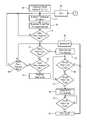
- FIG. 3is a flowchart showing one preferred method of the invention.
- FIG. 4is a graph illustrating certain changes in flow and pulsatility that may be associated with changes in pump speed under certain conditions.
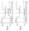
- FIGS. 5 and 6are graphs showing large and small flow increases that may be associated with a reduction in pump speed.
- FIG. 7is a matrix showing general correlations of pump speed, flow, and pulsatility with inflow and outflow obstructions.
- FIG. 8is a more detailed decision matrix for one preferred embodiment.
- FIG. 9is a graph showing pump speed adjustments and resultant changes in flow when correcting for a detected obstruction.
- FIG. 10is a flowchart showing a further method of the invention.
- FIG. 11is a state diagram corresponding to another preferred embodiment.
- a patient 10is shown in fragmentary front elevational view.
- Surgically implanted into the patient's abdominal cavity 11is the pumping portion 12 of a ventricular assist device.
- An inflow conduit 13conveys blood from the patient's left ventricle into the pumping portion 12
- an outflow conduit 14conveys blood from the pumping portion 12 to the patient's ascending thoracic aorta.
- a power cable 15extends from the pumping portion 12 outwardly of the patient's body via an incision to a compact controller 16 .
- a power sourcesuch as a battery pack worn on a belt about the patient's waist, and generally referenced with the numeral 17 , is connected with controller 16 .
- Each of the conduits 13 and 14may include a tubular metallic housing proximate the pumping portion 12 which may connect to elongated segments extending to the heart and ascending aorta, respectively.
- the conduitsare generally attached to the natural tissue by sutures through the use of a sewing ring or cuff so that blood flow communication is established and maintained.
- the distal end of the inflow conduit 13is inserted through the ventricle wall and into the heart in order to establish blood flow from the heart to the pumping portion 12 .
- FIG. 2illustrates a target flow Q Target at 20 and an actual flow value 25 that varies over time.
- a no flow threshold 21 and a low flow threshold 22define no flow region 23 and low flow region 24 , respectively, wherein appropriate alarms are generated by a pump control unit whenever actual flow dips into these regions.
- the trajectory of actual pump flow value 25may fall to a value below an expected minimum flow threshold 26 into a respective diagnostic region 27 .
- Expected minimum flow threshold 26may be obtained from a lookup table or a model based on empirically derived flow profiles that result from various inflow or outflow obstructions or various reductions in blood volume.
- the present inventionis configured to detect operation in region 27 and to take steps to identify a potential cause and a remedy in order to increase flow if possible.
- the present inventionenters a diagnostic state for identifying a potential cause of the impaired flow such as a partial or complete obstruction of the inflow conduit or the outflow conduit, or a condition wherein a flow is saturated for a given pump speed due to a limited blood volume resulting from dehydration, etc.
- a method of the inventionbegins in step 30 wherein a physician or other medical practitioner configures target values and performance limits pertaining to blood flow rate and pump speed to be provided for a particular patient.
- the circulatory assist devicethen monitors for physiological conditions such as heart rate or pump pulse rate in step 31 .
- a target flow rate and a target speedi.e., setpoint speed
- a speed setpointmay be determined according to other predetermined criteria such as a setpoint configured according to a static value chosen by a physician for the particular patient.
- eLPM pumpis an estimated average pump flow for a given pump speed. If not, then a return is made to step 31 and pump operation continues normally with the pump speed being determined by a target flow that is set according to physiological conditions.
- step 34determines whether the actual flow is less than a low flow threshold (LPM LowFlow ).
- LPM LowFlowa low flow threshold
- step 34preferably requires that the actual flow value be less than LPM LowFlow for greater than a predetermined low flow wait time (T LowFlowWait ).
- T LowFlowWaita predetermined low flow wait time
- step 36Checks are made in step 36 to determine whether the actual flow value has risen above the low flow threshold for greater than the low flow wait time, and a check is made in step 37 to determine whether the actual flow value is less than a no flow threshold (LPM NoFlow ) for at least a no flow wait time (T NoFlowWait ).
- LPM NoFlowno flow threshold
- T NoFlowWaitno flow wait time
- the value of T NoFlowWaitis less than the value of T LowFlowWait so that detection of a no flow condition has priority. If the actual flow value rises above the low flow threshold, then the warning is turned off in step 38 and a return is made to step 34 . If an actual flow value falls below the no flow threshold for the no flow diagnostic wait time, then a no flow warning is generated in step 40 to indicate that a greater urgency of taking corrective action.
- step 41While in a no flow warning state, a check is made in step 41 to determine whether the actual flow value rises above the no flow threshold for longer than the no flow wait time. When it does, the no flow warning is turned off in step 42 , the low flow warning is turned off in step 38 , and a return is made to step 34 .
- step 34determines that the actual flow value has not stayed below the low flow threshold for the low flow diagnostic wait time, then a check is made in step 43 to determine whether the actual flow value stays below the expected minimum flow value for at least an obstruction diagnostic wait time (T ObsDiagWait ) which is longer than both the low flow diagnostic wait time and the no flow diagnostic wait time. If not, then a check is made in step 44 to determine the actual flow value has recovered above the expected minimum flow value for at least the diagnostic wait time (T FlowDiagWait ), and if so, then a return is made to step 31 for nominal pump control. If the condition is not true in step 44 , then a return is made to step 34 for continuing to monitor for either a low flow condition or an obstructed condition. When the condition in step 43 is satisfied then the method proceeds to step 45 wherein a potential obstruction is diagnosed as described below.
- T ObsDiagWaitobstruction diagnostic wait time
- the present inventionis based in part on an observation that a nominal reduction in pump speed generally results in an increase in flow if an inflow obstructions exists.
- a pumpis operating at a first speed at 50 , but then a speed reduction 51 to a lower speed 52 is deliberately introduced. After a sufficient time to allow flow to stabilize at a new value for measurement, speed then increases at 53 back to the original speed at 54 .
- An actual pump flow Qhas an original value at 55 will rise to a higher flow at 56 during a reduced pump speed at 52 in the event that an inflow obstruction exists. If an outflow obstruction exists, then the actual flow instead decreases as shown at 57 during the time of reduced pump speed 52 .
- the change in pump speedmay also affect the pulsatility index (e.g., the difference between the maximum and minimum flows divided by the average maximum flow) such that an initial pulsatility at 60 decreases to a value at 61 in the presence of an inflow obstruction when pump speed is reduced at 52 .
- the pulsatility indexe.g., the difference between the maximum and minimum flows divided by the average maximum flow
- the pulsatilitywill increase at 62 during the speed reduction. Inspection of the change in flow resulting from a deliberate speed reduction may be sufficient to differentiate between an inflow obstruction and an outflow obstruction, but it may be coupled with an inspection of the change in pulsatility to potentially improve an identification.
- FIG. 5shows an inflow obstruction wherein a pump speed RPM setpoint and a pump flow eLPM pump are measured at a first time t 1 .
- Pump speedis reduced by a predetermined speed of RPM ObsDiag at a time t 2 .
- the actual pump flowhas stabilized at a new value representing an increase by more than a threshold designated LPM ObsDiag , which indicates the presence of the inflow obstruction.
- a plurality of speed modification trials of the type shown in FIG. 5are repeated in order to gather statistics for increasing a confidence level in detecting the inflow obstruction.
- the actual flow through the pumpincreases during the speed reduction by an incremental flow that is less than the value of LPM ObsDiag .
- the present inventiondoes not detect an inflow obstruction based on only the smaller increase in pump flow, but may require simultaneous change in pulsatility index in order to decide on the presence or absence of an inflow obstruction.
- an inflow or outflow obstructionmay be determined as shown in FIG. 7 .
- an inflow obstructionis detected.
- the speed reductioncreates a decreased resultant flow together with an increased pulsatility index, then an outflow obstruction is detected.
- the present inventionmay also distinguish between different levels of confidence in judging the presence of inflow and outflow obstructions for a saturated flow condition. For example, a large jump in flow being produced by a reduction in pump speed may always generate an indication of an inflow obstruction. Depending on whether pulsatility experiences a large drop or a small drop, the confidence of the inflow obstruction may be characterized as either probable or possible, respectively. As further shown in FIG. 8 , a small jump in flow may correlate with a likely inflow obstruction if the pulsatility also experienced a large drop. If both the jump in pump flow and the drop in pulsatility are small (i.e., less than respective thresholds), then the diagnostic decision may correspond to a “no call” with respect to whether there is any obstruction or a saturated flow.
- An outflow obstructionmay be detected according to FIG. 8 when a large drop in the flow is correlated with the reduction in pump speed. If the large drop in flow occurs with a large jump in pulsatility, then an outflow obstruction is probable. If associated with a small jump in pulsatility, then an outflow obstruction is classified as possible. When a small drop in pump flow occurs with a large jump in pulsatility, then an outflow obstruction is classified as likely, but if coupled with a small jump in pulsatility then no call is made.
- corresponding measurescan be taken to attempt to provide a greater flow or even restore the flow at least the expected minimum flow.
- a plurality of speed modification trialsincluding trials 65 and 66 are performed in order to assess the most likely obstruction.
- the pump speedPrior to the corrective action, the pump speed has a setpoint 67 and a corresponding flow value 68 .
- corrective actioncomprises gradually decreasing the pump speed at 70 to produce a gradual increase in flow at 71 .
- a predetermined minimum speed 72may preferably have been established by the physician based on the physiology of the patient, and if the speed reaches that minimum then no further changes would be made.
- corrective actioncomprises increasing the pump speed at 80 which results in an increased pump flow at 81 .
- the increasemay continue until either reaching a maximum pump speed 82 as previously determined by a physician or until pump flow reaches the expected minimum flow.
- step 85an actual flow value and a pulsatility index are measured at the current speed setpoint.
- step 86the pump speed is reduced by a preset amount.
- step 87a new flow value and pulsatility index are measured at the reduced speed.
- step 88A check is made in step 88 to determine whether a predetermined number of trials have been obtained. If not, speed is increased back to the original setpoint in step 89 and a return is made to step 85 .
- step 90the trials are classified in step 90 . Classification of each trial is performed in accordance with FIG. 8 , for example. The classified trials are then examined statistically in order to ensure that sufficient data is present to indicate either an inflow obstruction, outflow obstruction, or saturated flow. In a preferred embodiment, a majority of trials must indicate a respective condition.
- step 91a check is made to determine whether a majority of trials indicate that an inflow obstruction is either likely, possible, or probable. If so, then corrective action to increase pump flow begins at step 92 by dropping the pump speed by a predetermined amount. A check is performed in step 93 to determine whether the speed has been reduced to a predetermined minimum speed.
- step 94determines whether the latest drop in speed has instead caused a flow decrease. If not, then a return is made to step 92 to drop the speed once again. If a minimum speed is reached in step 93 , then the minimum speed is set as a new speed setpoint and the method returns to point A in FIG. 3 . In FIG. 3 , the method waits during a predetermined wait time (T EndDiagWait ) in step 110 before returning to normal operation. This periodic return to normal operation ensures that nominal operation is utilized whenever possible.
- T EndDiagWaita predetermined wait time
- step 94in the event that a flow decrease is detected in step 94 then the speed setpoint is set to the last speed that obtained a flow increase in step 96 and a return is made to point A.
- step 97determines whether a majority of trials indicate a saturated flow. If they do, then pump speed is dropped by a predetermined amount in step 98 .
- a checkis performed in step 99 to determine whether a minimum speed has been reached. If not, then a check is made in step 100 to determine whether a predetermined flow decrease has occurred (i.e., whether the flow has become unsaturated). If not, then a return is made to step 98 to drop speed once again. If a minimum speed is reached in step 99 , then the minimum speed is adopted as a new speed setpoint and the method returns to point A. If a flow decrease is detected in step 100 , then the current speed is used as a new speed setpoint and a return is made to point A.
- step 103determines whether a majority of trials indicated that an outflow obstruction is likely, possible, or probable. If not, then the flow problem has not been properly diagnosed and the method may retry to diagnose the obstruction in step 104 (e.g., by repeating a new plurality of trials at step 85 ). If a majority of trials indicate an outflow obstruction, then pump speed is increased by a set amount in step 105 . A check is made in step 106 to determine whether a maximum speed has been reached. If not, then a check is made in step 107 to determine whether the result flow has reached the expected minimum flow value.
- step 105If not, then a return is made to step 105 to further increase the speed. If a maximum speed is detected in step 106 , then the maximum speed is adopted as a new speed setpoint in step 108 and a return is made to point A. If the flow reaches the expected minimum flow value in step 107 , then the current speed is used as a new speed setpoint in step 109 and a return is made to point A.
- State 115is a normal pump control state wherein pump control may be implemented as according to U.S. Pat. No. 7,160,243, for example. As long as an actual flow remains greater than the expected minimum flow, operation continues to remain in state 115 . When pump flow falls below the expected minimum flow for greater than time T FlowDiagWait , then a transition is made from state 115 to a flow diagnostic state 116 . A transition is made back from state 116 to state 115 when the flow value remains above the expected minimum flow for greater than T FlowDiagWait . State 116 also checks for low flow.
- a transitionis made to a low flow alarm state 117 .
- a transitionwould be made back from state 117 to 116 whenever the actual flow remains greater than the low flow threshold for greater than T LowFlow .
- State 117monitors for a no flow condition by comparing actual flow with a no flow threshold. If actual flow is less than the no flow threshold for at least time T NoFlow then a transition is made to a no flow alarm state 118 . Flow continues to be compared with the no flow threshold and if it remains above the no flow threshold for at least T NoFlow then a transition is made back to flow diagnostic state 116 .
- a transitionis made to diagnose obstruction state 120 .
- a plurality of trialsare conducted by modifying the pump speed in order to attempt to classify either an inflow obstruction, outflow obstruction, or saturated flow condition.
- a transitionis made to state 121 for executing a speed reduction action.
- a transitionis made to state 123 for executing a speed increase action.
- a transitionis made to state 122 for executing a speed reduction action.
- transitionsare made to wait state 124 wherein the pump continues to operate at a new speed setpoint, thus achieving the best flow results obtainable under current conditions.
- a wait timeT EndDiagWait ) corresponding to an expected time in which conditions may eventually change
- a transitionis made back to normal pump control state 115 with a possible is reintroduction of corrective speed changes if flow again does not exceed the expected minimum flow.
Landscapes
- Health & Medical Sciences (AREA)
- Heart & Thoracic Surgery (AREA)
- Engineering & Computer Science (AREA)
- Cardiology (AREA)
- Biomedical Technology (AREA)
- Anesthesiology (AREA)
- Mechanical Engineering (AREA)
- Hematology (AREA)
- Life Sciences & Earth Sciences (AREA)
- Animal Behavior & Ethology (AREA)
- General Health & Medical Sciences (AREA)
- Public Health (AREA)
- Veterinary Medicine (AREA)
- Medical Informatics (AREA)
- External Artificial Organs (AREA)
Abstract
Description
Claims (16)
Priority Applications (1)
| Application Number | Priority Date | Filing Date | Title |
|---|---|---|---|
| US13/916,715US9056159B2 (en) | 2011-08-15 | 2013-06-13 | Non-invasive diagnostics for ventricle assist device |
Applications Claiming Priority (2)
| Application Number | Priority Date | Filing Date | Title |
|---|---|---|---|
| US13/209,814US8613696B2 (en) | 2011-08-15 | 2011-08-15 | Non-invasive diagnostics for ventricle assist device |
| US13/916,715US9056159B2 (en) | 2011-08-15 | 2013-06-13 | Non-invasive diagnostics for ventricle assist device |
Related Parent Applications (1)
| Application Number | Title | Priority Date | Filing Date |
|---|---|---|---|
| US13/209,814DivisionUS8613696B2 (en) | 2011-08-15 | 2011-08-15 | Non-invasive diagnostics for ventricle assist device |
Publications (2)
| Publication Number | Publication Date |
|---|---|
| US20130289337A1 US20130289337A1 (en) | 2013-10-31 |
| US9056159B2true US9056159B2 (en) | 2015-06-16 |
Family
ID=46598960
Family Applications (2)
| Application Number | Title | Priority Date | Filing Date |
|---|---|---|---|
| US13/209,814Active2031-12-09US8613696B2 (en) | 2011-08-15 | 2011-08-15 | Non-invasive diagnostics for ventricle assist device |
| US13/916,715Expired - Fee RelatedUS9056159B2 (en) | 2011-08-15 | 2013-06-13 | Non-invasive diagnostics for ventricle assist device |
Family Applications Before (1)
| Application Number | Title | Priority Date | Filing Date |
|---|---|---|---|
| US13/209,814Active2031-12-09US8613696B2 (en) | 2011-08-15 | 2011-08-15 | Non-invasive diagnostics for ventricle assist device |
Country Status (2)
| Country | Link |
|---|---|
| US (2) | US8613696B2 (en) |
| WO (1) | WO2013025296A1 (en) |
Cited By (12)
| Publication number | Priority date | Publication date | Assignee | Title |
|---|---|---|---|---|
| US10413649B2 (en) | 2014-10-01 | 2019-09-17 | Heartware, Inc. | Back up controller system with updating |
| US10722631B2 (en) | 2018-02-01 | 2020-07-28 | Shifamed Holdings, Llc | Intravascular blood pumps and methods of use and manufacture |
| US11185677B2 (en) | 2017-06-07 | 2021-11-30 | Shifamed Holdings, Llc | Intravascular fluid movement devices, systems, and methods of use |
| US11511103B2 (en) | 2017-11-13 | 2022-11-29 | Shifamed Holdings, Llc | Intravascular fluid movement devices, systems, and methods of use |
| US11654275B2 (en) | 2019-07-22 | 2023-05-23 | Shifamed Holdings, Llc | Intravascular blood pumps with struts and methods of use and manufacture |
| US11724089B2 (en) | 2019-09-25 | 2023-08-15 | Shifamed Holdings, Llc | Intravascular blood pump systems and methods of use and control thereof |
| US11964145B2 (en) | 2019-07-12 | 2024-04-23 | Shifamed Holdings, Llc | Intravascular blood pumps and methods of manufacture and use |
| US12102815B2 (en) | 2019-09-25 | 2024-10-01 | Shifamed Holdings, Llc | Catheter blood pumps and collapsible pump housings |
| US12121713B2 (en) | 2019-09-25 | 2024-10-22 | Shifamed Holdings, Llc | Catheter blood pumps and collapsible blood conduits |
| US12161857B2 (en) | 2018-07-31 | 2024-12-10 | Shifamed Holdings, Llc | Intravascular blood pumps and methods of use |
| US12220570B2 (en) | 2018-10-05 | 2025-02-11 | Shifamed Holdings, Llc | Intravascular blood pumps and methods of use |
| US12409310B2 (en) | 2019-12-11 | 2025-09-09 | Shifamed Holdings, Llc | Descending aorta and vena cava blood pumps |
Families Citing this family (24)
| Publication number | Priority date | Publication date | Assignee | Title |
|---|---|---|---|---|
| AU2012207146B2 (en) | 2011-01-21 | 2016-10-06 | Heartware, Inc. | Flow estimation in a blood pump |
| US9492601B2 (en) | 2011-01-21 | 2016-11-15 | Heartware, Inc. | Suction detection on an axial blood pump using BEMF data |
| JP5795286B2 (en)* | 2012-05-22 | 2015-10-14 | 株式会社堀場製作所 | Exhaust gas analysis system |
| WO2014197558A2 (en)* | 2013-06-04 | 2014-12-11 | Heartware, Inc. | Suction detection in an axial blood pump using bemf data |
| US9427508B2 (en)* | 2013-06-04 | 2016-08-30 | Heartware, Inc. | Axial flow pump pressure algorithm |
| US9623161B2 (en) | 2014-08-26 | 2017-04-18 | Tc1 Llc | Blood pump and method of suction detection |
| WO2017120451A2 (en) | 2016-01-06 | 2017-07-13 | Bivacor Inc. | Heart pump with impeller rotational speed control |
| EP3426317A4 (en)* | 2016-03-10 | 2019-02-27 | The University of Chicago | VENTRICULAR FILL PHASE SLOPE USED AS HIGH PULMONARY CAPILLARY PRESSURE INDICATOR AND / OR CARDIAC INDEX |
| EP3606577B1 (en) | 2017-04-05 | 2025-07-30 | Bivacor Inc. | Heart pump drive and bearing |
| AU2018279862B2 (en) | 2017-06-09 | 2023-07-06 | Abiomed, Inc. | Determination of cardiac parameters for modulation of blood pump support |
| DE102018208538A1 (en) | 2018-05-30 | 2019-12-05 | Kardion Gmbh | Intravascular blood pump and process for the production of electrical conductors |
| DE102018208879A1 (en) | 2018-06-06 | 2020-01-30 | Kardion Gmbh | Method for determining a total fluid volume flow in the area of an implanted, vascular support system |
| DE102018208899A1 (en) | 2018-06-06 | 2019-12-12 | Kardion Gmbh | A method for determining the speed of sound in a fluid in the region of an implanted vascular support system |
| DE102018208862A1 (en) | 2018-06-06 | 2019-12-12 | Kardion Gmbh | Implantable vascular support system |
| DE102018208945A1 (en) | 2018-06-06 | 2019-12-12 | Kardion Gmbh | An analysis device and method for analyzing a viscosity of a fluid |
| DE102018208929A1 (en) | 2018-06-06 | 2019-12-12 | Kardion Gmbh | A method of determining a flow rate of fluid flowing through an implanted vascular support system |
| DE102018208933A1 (en) | 2018-06-06 | 2019-12-12 | Kardion Gmbh | A method of determining a flow rate of fluid flowing through an implanted vascular support system |
| DE102018208936A1 (en) | 2018-06-06 | 2019-12-12 | Kardion Gmbh | Determining device and method for determining a viscosity of a fluid |
| DE102018208913A1 (en) | 2018-06-06 | 2019-12-12 | Kardion Gmbh | A method of operating an implanted ventricular assist device |
| EP3809960B1 (en)* | 2018-06-19 | 2024-12-11 | Abiomed, Inc. | Systems for system identification |
| DE102018210076A1 (en) | 2018-06-21 | 2019-12-24 | Kardion Gmbh | Method and device for detecting a state of wear of a cardiac support system, method and device for operating a cardiac support system and cardiac support system |
| US10960118B2 (en) | 2018-07-31 | 2021-03-30 | Abiomed, Inc. | Systems and methods for controlling a heart pump to minimize myocardial oxygen consumption |
| US11666281B2 (en)* | 2019-02-28 | 2023-06-06 | Medtronic, Inc. | Detection of hypertension in LVAD patients using speed change |
| CN115227964B (en)* | 2022-09-21 | 2022-12-27 | 深圳核心医疗科技有限公司 | Flow velocity control method and device |
Citations (19)
| Publication number | Priority date | Publication date | Assignee | Title |
|---|---|---|---|---|
| US5965089A (en) | 1996-10-04 | 1999-10-12 | United States Surgical Corporation | Circulatory support system |
| US6066086A (en) | 1996-11-01 | 2000-05-23 | Nimbus, Inc. | Speed control system for implanted blood pumps |
| US6572530B1 (en)* | 1997-12-27 | 2003-06-03 | Jms Co., Ltd. | Blood circulation auxiliary device using continuous blood flow pump and diagnosis device for blood circulation state in organism |
| US6949066B2 (en) | 2002-08-21 | 2005-09-27 | World Heart Corporation | Rotary blood pump diagnostics and cardiac output controller |
| US6991595B2 (en) | 2002-04-19 | 2006-01-31 | Thoratec Corporation | Adaptive speed control for blood pump |
| US7033147B2 (en) | 2002-01-28 | 2006-04-25 | Terumo Kabushiki Kaisha | Centrifugal fluid pump assembly with flow rate calculating section |
| US7160243B2 (en) | 2004-03-25 | 2007-01-09 | Terumo Corporation | Method and system for controlling blood pump flow |
| US7175588B2 (en) | 2002-01-08 | 2007-02-13 | Micromed Technology, Inc. | Method and system for detecting ventricular collapse |
| US20070142923A1 (en) | 2005-11-04 | 2007-06-21 | Ayre Peter J | Control systems for rotary blood pumps |
| US7284956B2 (en) | 2002-09-10 | 2007-10-23 | Miwatec Co., Ltd. | Methods and apparatus for controlling a continuous flow rotary blood pump |
| US20070265703A1 (en) | 2006-05-09 | 2007-11-15 | Ventrassist Pty Ltd. | Pulsatile control system for a rotary blood pump |
| US20090005632A1 (en) | 2004-09-07 | 2009-01-01 | Heinrich Schima | Method and System for Physiologic Control of a Blood Pump |
| US7645225B2 (en) | 2000-03-27 | 2010-01-12 | Alexander Medvedev | Chronic performance control system for rotodynamic blood pumps |
| US20100042259A1 (en) | 2007-02-09 | 2010-02-18 | Simons Antoine P | Method and apparatus for monitoring and optimizing blood circulation generated by a pump |
| US20100174231A1 (en) | 2009-01-07 | 2010-07-08 | Cleveland Clinic Foundation | Method for physiologic control of a continuous flow total artificial heart |
| US7951062B2 (en) | 2002-01-07 | 2011-05-31 | Micromed Technology, Inc. | Blood pump system and method of operation |
| US7963905B2 (en) | 2006-10-11 | 2011-06-21 | Thoratec Corporation | Control system for a blood pump |
| US20110160519A1 (en) | 2007-08-03 | 2011-06-30 | Andreas Arndt | Rotational pump and methods for controlling rotational pumps |
| US20110313238A1 (en) | 2010-06-22 | 2011-12-22 | Reichenbach Steven H | Fluid delivery system and method for monitoring fluid delivery system |
- 2011
- 2011-08-15USUS13/209,814patent/US8613696B2/enactiveActive
- 2012
- 2012-07-13WOPCT/US2012/046589patent/WO2013025296A1/enactiveApplication Filing
- 2013
- 2013-06-13USUS13/916,715patent/US9056159B2/ennot_activeExpired - Fee Related
Patent Citations (23)
| Publication number | Priority date | Publication date | Assignee | Title |
|---|---|---|---|---|
| US5965089A (en) | 1996-10-04 | 1999-10-12 | United States Surgical Corporation | Circulatory support system |
| US6716189B1 (en) | 1996-10-04 | 2004-04-06 | United States Surgical Corporation | Circulatory support system |
| US6066086A (en) | 1996-11-01 | 2000-05-23 | Nimbus, Inc. | Speed control system for implanted blood pumps |
| US6572530B1 (en)* | 1997-12-27 | 2003-06-03 | Jms Co., Ltd. | Blood circulation auxiliary device using continuous blood flow pump and diagnosis device for blood circulation state in organism |
| US7645225B2 (en) | 2000-03-27 | 2010-01-12 | Alexander Medvedev | Chronic performance control system for rotodynamic blood pumps |
| US7951062B2 (en) | 2002-01-07 | 2011-05-31 | Micromed Technology, Inc. | Blood pump system and method of operation |
| US7175588B2 (en) | 2002-01-08 | 2007-02-13 | Micromed Technology, Inc. | Method and system for detecting ventricular collapse |
| US7033147B2 (en) | 2002-01-28 | 2006-04-25 | Terumo Kabushiki Kaisha | Centrifugal fluid pump assembly with flow rate calculating section |
| US6991595B2 (en) | 2002-04-19 | 2006-01-31 | Thoratec Corporation | Adaptive speed control for blood pump |
| US6949066B2 (en) | 2002-08-21 | 2005-09-27 | World Heart Corporation | Rotary blood pump diagnostics and cardiac output controller |
| US7284956B2 (en) | 2002-09-10 | 2007-10-23 | Miwatec Co., Ltd. | Methods and apparatus for controlling a continuous flow rotary blood pump |
| US7160243B2 (en) | 2004-03-25 | 2007-01-09 | Terumo Corporation | Method and system for controlling blood pump flow |
| US20090005632A1 (en) | 2004-09-07 | 2009-01-01 | Heinrich Schima | Method and System for Physiologic Control of a Blood Pump |
| US20070142923A1 (en) | 2005-11-04 | 2007-06-21 | Ayre Peter J | Control systems for rotary blood pumps |
| US20110015465A1 (en) | 2005-11-04 | 2011-01-20 | Peter Joseph Ayre | Control systems for rotary blood pumps |
| US20070265703A1 (en) | 2006-05-09 | 2007-11-15 | Ventrassist Pty Ltd. | Pulsatile control system for a rotary blood pump |
| US7850594B2 (en) | 2006-05-09 | 2010-12-14 | Thoratec Corporation | Pulsatile control system for a rotary blood pump |
| US20110054239A1 (en) | 2006-05-09 | 2011-03-03 | Thoratec Corporation | Pulsatile Control System for a Rotary Blood Pump |
| US7963905B2 (en) | 2006-10-11 | 2011-06-21 | Thoratec Corporation | Control system for a blood pump |
| US20100042259A1 (en) | 2007-02-09 | 2010-02-18 | Simons Antoine P | Method and apparatus for monitoring and optimizing blood circulation generated by a pump |
| US20110160519A1 (en) | 2007-08-03 | 2011-06-30 | Andreas Arndt | Rotational pump and methods for controlling rotational pumps |
| US20100174231A1 (en) | 2009-01-07 | 2010-07-08 | Cleveland Clinic Foundation | Method for physiologic control of a continuous flow total artificial heart |
| US20110313238A1 (en) | 2010-06-22 | 2011-12-22 | Reichenbach Steven H | Fluid delivery system and method for monitoring fluid delivery system |
Non-Patent Citations (3)
| Title |
|---|
| Kenji Araki, et al., Detection of Total Assist and Sucking Points Based on Pulsatility of a Continuous Flow Artificial Heart: In Vitro Evaluation, ASAIO Journal 1998, pp. M708-M711. |
| Mitsuo Oshikawa, et al., Detection of Total Assist and Sucking Points Based on the Pulsatility of a Continuous Flow Artificial Heart: In Vivo Evaluation, ASAIO Journal 1998, pp. M704-M707. |
| R. Kosaka, et al., Operating Point Control System for a Continuous Flow Artificial Heart: In Vitro Study, ASAIO Journal 2003, pp. 259-264. |
Cited By (15)
| Publication number | Priority date | Publication date | Assignee | Title |
|---|---|---|---|---|
| US10413649B2 (en) | 2014-10-01 | 2019-09-17 | Heartware, Inc. | Back up controller system with updating |
| US11717670B2 (en) | 2017-06-07 | 2023-08-08 | Shifamed Holdings, LLP | Intravascular fluid movement devices, systems, and methods of use |
| US11185677B2 (en) | 2017-06-07 | 2021-11-30 | Shifamed Holdings, Llc | Intravascular fluid movement devices, systems, and methods of use |
| US11511103B2 (en) | 2017-11-13 | 2022-11-29 | Shifamed Holdings, Llc | Intravascular fluid movement devices, systems, and methods of use |
| US11229784B2 (en) | 2018-02-01 | 2022-01-25 | Shifamed Holdings, Llc | Intravascular blood pumps and methods of use and manufacture |
| US10722631B2 (en) | 2018-02-01 | 2020-07-28 | Shifamed Holdings, Llc | Intravascular blood pumps and methods of use and manufacture |
| US12076545B2 (en) | 2018-02-01 | 2024-09-03 | Shifamed Holdings, Llc | Intravascular blood pumps and methods of use and manufacture |
| US12161857B2 (en) | 2018-07-31 | 2024-12-10 | Shifamed Holdings, Llc | Intravascular blood pumps and methods of use |
| US12220570B2 (en) | 2018-10-05 | 2025-02-11 | Shifamed Holdings, Llc | Intravascular blood pumps and methods of use |
| US11964145B2 (en) | 2019-07-12 | 2024-04-23 | Shifamed Holdings, Llc | Intravascular blood pumps and methods of manufacture and use |
| US11654275B2 (en) | 2019-07-22 | 2023-05-23 | Shifamed Holdings, Llc | Intravascular blood pumps with struts and methods of use and manufacture |
| US11724089B2 (en) | 2019-09-25 | 2023-08-15 | Shifamed Holdings, Llc | Intravascular blood pump systems and methods of use and control thereof |
| US12102815B2 (en) | 2019-09-25 | 2024-10-01 | Shifamed Holdings, Llc | Catheter blood pumps and collapsible pump housings |
| US12121713B2 (en) | 2019-09-25 | 2024-10-22 | Shifamed Holdings, Llc | Catheter blood pumps and collapsible blood conduits |
| US12409310B2 (en) | 2019-12-11 | 2025-09-09 | Shifamed Holdings, Llc | Descending aorta and vena cava blood pumps |
Also Published As
| Publication number | Publication date |
|---|---|
| US8613696B2 (en) | 2013-12-24 |
| US20130289337A1 (en) | 2013-10-31 |
| US20130046129A1 (en) | 2013-02-21 |
| WO2013025296A1 (en) | 2013-02-21 |
Similar Documents
| Publication | Publication Date | Title |
|---|---|---|
| US9056159B2 (en) | Non-invasive diagnostics for ventricle assist device | |
| US7963905B2 (en) | Control system for a blood pump | |
| US11554260B2 (en) | Multi-input speed response algorithm for a blood pump | |
| US10905809B2 (en) | Method for operating a pump device and a pump device | |
| US20070282298A1 (en) | System and method for controlling a rotary blood pump | |
| US8303482B2 (en) | Method and system for physiologic control of a blood pump | |
| JP5500348B2 (en) | Method and apparatus for monitoring and optimizing blood circulation produced by a pump | |
| US20200254165A1 (en) | Suction detection methods and devices | |
| EP2945661B1 (en) | Backflow detection for centrifugal blood pump | |
| US8657874B2 (en) | Method for physiologic control of a continuous flow total artificial heart | |
| US20060241335A1 (en) | Method and system for physiologic control of a blood pump | |
| CN111989128A (en) | Current-speed relationship for transient pumping detection algorithms in LVAD | |
| EP3139974B1 (en) | Artificial heart system implementing suction recognition and avoidance | |
| CN111655306A (en) | Early Warning of LVAD Thrombosis | |
| WO2015195916A1 (en) | Methods and devices for identifying suction events | |
| US20230083542A1 (en) | System and method for ventricular assistance support during extracorporeal membrane oxygenation | |
| AU2007221905B2 (en) | Control System for a Blood Pump | |
| AU2007201724B2 (en) | System and Method of Controlling a Rotary Blood Pump | |
| HK1139341B (en) | Apparatus for monitoring and optimizing blood circulation generated by a pump |
Legal Events
| Date | Code | Title | Description |
|---|---|---|---|
| AS | Assignment | Owner name:TERUMO KABUSHIKI KAISHA, JAPAN Free format text:ASSIGNMENT OF ASSIGNORS INTEREST;ASSIGNORS:MEDVEDEV, ALEXANDER;SAMI, MUHAMMAD K.;YANAI, MASAMICHI;REEL/FRAME:030604/0264 Effective date:20130612 | |
| AS | Assignment | Owner name:THORATEC CORPORATION, CALIFORNIA Free format text:ASSIGNMENT OF ASSIGNORS INTEREST;ASSIGNOR:TERUMO KABUSHIKI KAISHA;REEL/FRAME:031016/0364 Effective date:20130630 | |
| STCF | Information on status: patent grant | Free format text:PATENTED CASE | |
| AS | Assignment | Owner name:THORATEC LLC, CALIFORNIA Free format text:CHANGE OF NAME;ASSIGNOR:THORATEC CORPORATION;REEL/FRAME:041428/0327 Effective date:20151112 Owner name:TC1 LLC, CALIFORNIA Free format text:ASSIGNMENT OF ASSIGNORS INTEREST;ASSIGNOR:THORATEC LLC;REEL/FRAME:041428/0685 Effective date:20161114 | |
| MAFP | Maintenance fee payment | Free format text:PAYMENT OF MAINTENANCE FEE, 4TH YEAR, LARGE ENTITY (ORIGINAL EVENT CODE: M1551); ENTITY STATUS OF PATENT OWNER: LARGE ENTITY Year of fee payment:4 | |
| FEPP | Fee payment procedure | Free format text:MAINTENANCE FEE REMINDER MAILED (ORIGINAL EVENT CODE: REM.); ENTITY STATUS OF PATENT OWNER: LARGE ENTITY | |
| LAPS | Lapse for failure to pay maintenance fees | Free format text:PATENT EXPIRED FOR FAILURE TO PAY MAINTENANCE FEES (ORIGINAL EVENT CODE: EXP.); ENTITY STATUS OF PATENT OWNER: LARGE ENTITY | |
| STCH | Information on status: patent discontinuation | Free format text:PATENT EXPIRED DUE TO NONPAYMENT OF MAINTENANCE FEES UNDER 37 CFR 1.362 | |
| FP | Lapsed due to failure to pay maintenance fee | Effective date:20230616 |