US9056000B2 - Flexible stent-graft - Google Patents
Flexible stent-graftDownload PDFInfo
- Publication number
- US9056000B2 US9056000B2US11/572,908US57290806AUS9056000B2US 9056000 B2US9056000 B2US 9056000B2US 57290806 AUS57290806 AUS 57290806AUS 9056000 B2US9056000 B2US 9056000B2
- Authority
- US
- United States
- Prior art keywords
- stent
- apexes
- graft
- sloping
- wave
- Prior art date
- Legal status (The legal status is an assumption and is not a legal conclusion. Google has not performed a legal analysis and makes no representation as to the accuracy of the status listed.)
- Active, expires
Links
- 206010002329AneurysmDiseases0.000description21
- 238000011282treatmentMethods0.000description10
- 208000002223abdominal aortic aneurysmDiseases0.000description9
- 210000002376aorta thoracicAnatomy0.000description9
- 238000000034methodMethods0.000description9
- -1polytetrafluorethylenePolymers0.000description9
- 208000007474aortic aneurysmDiseases0.000description8
- 230000017531blood circulationEffects0.000description8
- 210000004204blood vesselAnatomy0.000description8
- 239000000463materialSubstances0.000description8
- 239000000560biocompatible materialSubstances0.000description7
- 210000003090iliac arteryAnatomy0.000description7
- 229910045601alloyInorganic materials0.000description6
- 239000000956alloySubstances0.000description6
- 210000000702aorta abdominalAnatomy0.000description6
- 230000003447ipsilateral effectEffects0.000description6
- BASFCYQUMIYNBI-UHFFFAOYSA-NplatinumChemical compound[Pt]BASFCYQUMIYNBI-UHFFFAOYSA-N0.000description6
- 208000007536ThrombosisDiseases0.000description4
- 239000008280bloodSubstances0.000description4
- 210000004369bloodAnatomy0.000description4
- 229910000684Cobalt-chromeInorganic materials0.000description3
- JOYRKODLDBILNP-UHFFFAOYSA-NEthyl urethaneChemical compoundCCOC(N)=OJOYRKODLDBILNP-UHFFFAOYSA-N0.000description3
- 239000004677NylonSubstances0.000description3
- 239000004952PolyamideSubstances0.000description3
- 239000004743PolypropyleneSubstances0.000description3
- 229910001260Pt alloyInorganic materials0.000description3
- 229920002334SpandexPolymers0.000description3
- 201000008982Thoracic Aortic AneurysmDiseases0.000description3
- RTAQQCXQSZGOHL-UHFFFAOYSA-NTitaniumChemical compound[Ti]RTAQQCXQSZGOHL-UHFFFAOYSA-N0.000description3
- 229910001080W alloyInorganic materials0.000description3
- 210000000709aortaAnatomy0.000description3
- 230000036772blood pressureEffects0.000description3
- 239000010952cobalt-chromeSubstances0.000description3
- 238000013329compoundingMethods0.000description3
- 229910000701elgiloys (Co-Cr-Ni Alloy)Inorganic materials0.000description3
- 239000004744fabricSubstances0.000description3
- HCDGVLDPFQMKDK-UHFFFAOYSA-NhexafluoropropyleneChemical groupFC(F)=C(F)C(F)(F)FHCDGVLDPFQMKDK-UHFFFAOYSA-N0.000description3
- HLXZNVUGXRDIFK-UHFFFAOYSA-Nnickel titaniumChemical compound[Ti].[Ti].[Ti].[Ti].[Ti].[Ti].[Ti].[Ti].[Ti].[Ti].[Ti].[Ni].[Ni].[Ni].[Ni].[Ni].[Ni].[Ni].[Ni].[Ni].[Ni].[Ni].[Ni].[Ni].[Ni]HLXZNVUGXRDIFK-UHFFFAOYSA-N0.000description3
- 229910001000nickel titaniumInorganic materials0.000description3
- 229920001778nylonPolymers0.000description3
- 229920002647polyamidePolymers0.000description3
- 229920000728polyesterPolymers0.000description3
- 229920000139polyethylene terephthalatePolymers0.000description3
- 239000005020polyethylene terephthalateSubstances0.000description3
- 229920001155polypropylenePolymers0.000description3
- 229920001343polytetrafluoroethylenePolymers0.000description3
- 210000002254renal arteryAnatomy0.000description3
- 239000004759spandexSubstances0.000description3
- 239000010935stainless steelSubstances0.000description3
- 229910001220stainless steelInorganic materials0.000description3
- 238000001356surgical procedureMethods0.000description3
- 239000010936titaniumSubstances0.000description3
- 229910052719titaniumInorganic materials0.000description3
- 230000015572biosynthetic processEffects0.000description2
- 238000005520cutting processMethods0.000description2
- 230000006378damageEffects0.000description2
- 238000002513implantationMethods0.000description2
- 230000001788irregularEffects0.000description2
- 208000019553vascular diseaseDiseases0.000description2
- 0CC1C*CC1Chemical compoundCC1C*CC10.000description1
- 208000036829Device dislocationDiseases0.000description1
- 238000012276Endovascular treatmentMethods0.000description1
- 208000032843HemorrhageDiseases0.000description1
- 206010020772HypertensionDiseases0.000description1
- 208000027418Wounds and injuryDiseases0.000description1
- 230000009286beneficial effectEffects0.000description1
- 230000036770blood supplyEffects0.000description1
- 238000003486chemical etchingMethods0.000description1
- 201000010099diseaseDiseases0.000description1
- 208000037265diseases, disorders, signs and symptomsDiseases0.000description1
- 238000011010flushing procedureMethods0.000description1
- 208000014674injuryDiseases0.000description1
- 238000003698laser cuttingMethods0.000description1
- 238000003754machiningMethods0.000description1
- 238000002844meltingMethods0.000description1
- 230000008018meltingEffects0.000description1
- 238000002324minimally invasive surgeryMethods0.000description1
- 210000005036nerveAnatomy0.000description1
- 210000000056organAnatomy0.000description1
- 230000002688persistenceEffects0.000description1
- 238000005245sinteringMethods0.000description1
- 210000003270subclavian arteryAnatomy0.000description1
- 238000003466weldingMethods0.000description1
Images


Classifications
- A—HUMAN NECESSITIES
- A61—MEDICAL OR VETERINARY SCIENCE; HYGIENE
- A61F—FILTERS IMPLANTABLE INTO BLOOD VESSELS; PROSTHESES; DEVICES PROVIDING PATENCY TO, OR PREVENTING COLLAPSING OF, TUBULAR STRUCTURES OF THE BODY, e.g. STENTS; ORTHOPAEDIC, NURSING OR CONTRACEPTIVE DEVICES; FOMENTATION; TREATMENT OR PROTECTION OF EYES OR EARS; BANDAGES, DRESSINGS OR ABSORBENT PADS; FIRST-AID KITS
- A61F2/00—Filters implantable into blood vessels; Prostheses, i.e. artificial substitutes or replacements for parts of the body; Appliances for connecting them with the body; Devices providing patency to, or preventing collapsing of, tubular structures of the body, e.g. stents
- A61F2/02—Prostheses implantable into the body
- A61F2/04—Hollow or tubular parts of organs, e.g. bladders, tracheae, bronchi or bile ducts
- A61F2/06—Blood vessels
- A61F2/07—Stent-grafts
- A—HUMAN NECESSITIES
- A61—MEDICAL OR VETERINARY SCIENCE; HYGIENE
- A61F—FILTERS IMPLANTABLE INTO BLOOD VESSELS; PROSTHESES; DEVICES PROVIDING PATENCY TO, OR PREVENTING COLLAPSING OF, TUBULAR STRUCTURES OF THE BODY, e.g. STENTS; ORTHOPAEDIC, NURSING OR CONTRACEPTIVE DEVICES; FOMENTATION; TREATMENT OR PROTECTION OF EYES OR EARS; BANDAGES, DRESSINGS OR ABSORBENT PADS; FIRST-AID KITS
- A61F2/00—Filters implantable into blood vessels; Prostheses, i.e. artificial substitutes or replacements for parts of the body; Appliances for connecting them with the body; Devices providing patency to, or preventing collapsing of, tubular structures of the body, e.g. stents
- A61F2/82—Devices providing patency to, or preventing collapsing of, tubular structures of the body, e.g. stents
- A61F2/86—Stents in a form characterised by the wire-like elements; Stents in the form characterised by a net-like or mesh-like structure
- A61F2/89—Stents in a form characterised by the wire-like elements; Stents in the form characterised by a net-like or mesh-like structure the wire-like elements comprising two or more adjacent rings flexibly connected by separate members
- A—HUMAN NECESSITIES
- A61—MEDICAL OR VETERINARY SCIENCE; HYGIENE
- A61F—FILTERS IMPLANTABLE INTO BLOOD VESSELS; PROSTHESES; DEVICES PROVIDING PATENCY TO, OR PREVENTING COLLAPSING OF, TUBULAR STRUCTURES OF THE BODY, e.g. STENTS; ORTHOPAEDIC, NURSING OR CONTRACEPTIVE DEVICES; FOMENTATION; TREATMENT OR PROTECTION OF EYES OR EARS; BANDAGES, DRESSINGS OR ABSORBENT PADS; FIRST-AID KITS
- A61F2/00—Filters implantable into blood vessels; Prostheses, i.e. artificial substitutes or replacements for parts of the body; Appliances for connecting them with the body; Devices providing patency to, or preventing collapsing of, tubular structures of the body, e.g. stents
- A61F2/02—Prostheses implantable into the body
- A61F2/04—Hollow or tubular parts of organs, e.g. bladders, tracheae, bronchi or bile ducts
- A61F2/06—Blood vessels
- A61F2002/065—Y-shaped blood vessels
- A61F2002/067—Y-shaped blood vessels modular
- A—HUMAN NECESSITIES
- A61—MEDICAL OR VETERINARY SCIENCE; HYGIENE
- A61F—FILTERS IMPLANTABLE INTO BLOOD VESSELS; PROSTHESES; DEVICES PROVIDING PATENCY TO, OR PREVENTING COLLAPSING OF, TUBULAR STRUCTURES OF THE BODY, e.g. STENTS; ORTHOPAEDIC, NURSING OR CONTRACEPTIVE DEVICES; FOMENTATION; TREATMENT OR PROTECTION OF EYES OR EARS; BANDAGES, DRESSINGS OR ABSORBENT PADS; FIRST-AID KITS
- A61F2/00—Filters implantable into blood vessels; Prostheses, i.e. artificial substitutes or replacements for parts of the body; Appliances for connecting them with the body; Devices providing patency to, or preventing collapsing of, tubular structures of the body, e.g. stents
- A61F2/02—Prostheses implantable into the body
- A61F2/04—Hollow or tubular parts of organs, e.g. bladders, tracheae, bronchi or bile ducts
- A61F2/06—Blood vessels
- A61F2/07—Stent-grafts
- A61F2002/075—Stent-grafts the stent being loosely attached to the graft material, e.g. by stitching
- A—HUMAN NECESSITIES
- A61—MEDICAL OR VETERINARY SCIENCE; HYGIENE
- A61F—FILTERS IMPLANTABLE INTO BLOOD VESSELS; PROSTHESES; DEVICES PROVIDING PATENCY TO, OR PREVENTING COLLAPSING OF, TUBULAR STRUCTURES OF THE BODY, e.g. STENTS; ORTHOPAEDIC, NURSING OR CONTRACEPTIVE DEVICES; FOMENTATION; TREATMENT OR PROTECTION OF EYES OR EARS; BANDAGES, DRESSINGS OR ABSORBENT PADS; FIRST-AID KITS
- A61F2230/00—Geometry of prostheses classified in groups A61F2/00 - A61F2/26 or A61F2/82 or A61F9/00 or A61F11/00 or subgroups thereof
- A61F2230/0063—Three-dimensional shapes
- A61F2230/0067—Three-dimensional shapes conical
- A—HUMAN NECESSITIES
- A61—MEDICAL OR VETERINARY SCIENCE; HYGIENE
- A61F—FILTERS IMPLANTABLE INTO BLOOD VESSELS; PROSTHESES; DEVICES PROVIDING PATENCY TO, OR PREVENTING COLLAPSING OF, TUBULAR STRUCTURES OF THE BODY, e.g. STENTS; ORTHOPAEDIC, NURSING OR CONTRACEPTIVE DEVICES; FOMENTATION; TREATMENT OR PROTECTION OF EYES OR EARS; BANDAGES, DRESSINGS OR ABSORBENT PADS; FIRST-AID KITS
- A61F2250/00—Special features of prostheses classified in groups A61F2/00 - A61F2/26 or A61F2/82 or A61F9/00 or A61F11/00 or subgroups thereof
- A61F2250/0014—Special features of prostheses classified in groups A61F2/00 - A61F2/26 or A61F2/82 or A61F9/00 or A61F11/00 or subgroups thereof having different values of a given property or geometrical feature, e.g. mechanical property or material property, at different locations within the same prosthesis
- A61F2250/0039—Special features of prostheses classified in groups A61F2/00 - A61F2/26 or A61F2/82 or A61F9/00 or A61F11/00 or subgroups thereof having different values of a given property or geometrical feature, e.g. mechanical property or material property, at different locations within the same prosthesis differing in diameter
Definitions
- the inventions described belowrelate the field of medical devices for use in treatment of vascular diseases. More specifically, the inventions described below relate to stent grafts for use in the treatment of thoracic aortic aneurysms and bifurcated stent grafts for use in treatment of abdominal aortic aneurysms.
- a stent graftis a medical device comprising a tube graft material supported by a metallic wire frame that may be used in the treatment of vascular diseases including aneurysms. Blood pressure within the diseased portion of the blood vessel can cause the aneurysm to rupture and hemorrhage.
- Stent-graftscan be used in the treatment of aneurysms, including thoracic aortic aneurysms and abdominal aortic aneurysms, by isolating the blood from the aneurysms.
- stentsare deployed by placing them in a sheath of a delivery system and delivering the stent to the location where the aneurysm lies.
- the stent-graftAfter being deployed, the stent-graft expands and anchors onto healthy portions of the blood vessel on both ends adjoining the aneurysm. Once installed, blood flows through the tubular stent graft and the diseased portion of the blood vessel is isolated from the pressure of flowing blood.
- a wide range of endovascular stent graftshave been developed that are adapted for temporary or permanent implantation within a body lumen including the abdominal aorta or thoracic aorta. These stent grafts provide uniquely beneficial structures that modify the mechanics of the targeted vessel wall.
- existing stent-graftshave many drawbacks and may be restricted in their usefulness and applicability to certain procedures.
- tubular stent graftshave been used in the treatment of aortic aneurysms, including abdominal aortic aneurysms and thoracic aortic aneurysms close to the aortic arch.
- the aortic archcomprises a sharp curve and disease and deformation of this blood vessel usually occurs close to the curved portion of the vessel.
- treatment of aneurysms in the aortic archcalls for flexibility and high performance in the stent-graft so that it can easily flex and adapt to the shape of the blood vessel. If the stent graft is not flexible, it cannot attach conformably to the wall of the blood vessel and may potentially kink.
- a kink in the stent graftwill not only weaken the fixation of the stent graft to the vessel wall, but it may also raise the blood pressure within the graft due to the uneven or smaller inner diameter of the graft.
- High blood pressure in deployed stent graftscan lead to a higher flushing force of blood flow on the stent graft and a rise of the risk of stent graft migration as well. If the stent graft migrates within the arotic arch, it not only fails to isolate the blood from the aneurysm, but also may cover other branch vessels extending from the aorta.
- Endoleakageis a major complication of endovascular treatment of aortic aneurysms. Endoleakage is the persistence of blood flow into the aneurysm sac outside the stent graft. When endoleakage occurs, the aneurysm is not fully isolated from blood flow within the patient's blood vessel and risk of a potentially fatal rupture of the aneurysm remains. Most endoleakage occurs at the proximal portion of the stent graft once the stent graft is inserted into a patient. Improved deformability of the proximal end of stent grafts can prevent proximal endoleakage.
- stent graft designstypically comprise an open stent that is not fully covered with graft material.
- Stentsmay comprise a series of waveforms or undulations having apexes.
- aneurysmWhen aneurysm are located very close to an important branch vessel, the surgeon will position the proximal end of graft member with the open stent close to the distal end of the branch port and the open stent will cover the branch port in an effort to avoid occluding the branch.
- This method of stent graft placementdoes not occlude the branch port, improves the fixation of the stent graft to the vessel and strengthens the proximal radial supporting force of graft member.
- stent grafts with open stentshave many advantages, use and placement of stent grafts having open stents is not without its risks.
- the proximal apexes of the undulations of the open stentexpand to their full diameter while the distal apexes of the undulations are still restricted.
- the expanded proximal apexescan overturn within the vessel. Overturning occurs when one or more complete undulations or one or more of the proximal apexes expand and turn backwards.
- overturned apexescan stick to the wall of vessel.
- overturned undulations and apexesdeform the proximal profile of the graft member and prevent the proximal end of the graft member from conformably attaching to the wall of vessel.
- a stent graft deformed in this mannerincreases the risk of proximal endoleakage as well as increases the risk of vessel rupture due to sticking of overturned apexes into the vessel wall.
- One method used to reduce the potential of overturn of the apexes of the open stentis to utilize longitudinally longer the open stents. Longer stents, however, not only cover the intended branch vessel, but also risk covering one more branch vessels not intended to be covered. Because stents are foreign objects within the human body, there is potential for the formation of blood clots known as thrombus on the surface of the stent wire. Since thrombus formation is unstable, there is a risk for it to be flushed away from the stent. When an open stent covers a branch, the thrombus may be flushed into the branch vessel and occlude some other smaller vessels of the branch. Occlusion of branch vessels can potentially be fatal to the patient. Less severe complications of open stents covering the port of the branch vessel include increased difficulty in future performance of minimally invasive surgery within the branch vessel due to vessel obstruction.
- bifurcated stent graft designstwo branches of varying lengths extended from a trunk portion of the graft. The longer branch is typically called the ipsilateral iliac branch and the shorter branch is typically called the contralateral iliac branch.
- the distal part of ipsilateral branchis often positioned within the ipsilateral iliac artery and the entire contralateral iliac branch portion is positioned within the abdominal aorta.
- the abdominal aortais the vessel that usually contains a large aneurysm sac or bubble.
- a branch stent graft extensionpositioned by a guide wire to be place in and joined to the bifurcated stent graft within the short branch, contralateral iliac branch.
- the procedure placing the guiding wire into the contralateral iliac branchis difficult.
- the contralateral iliac branchtypically has an inner diameter of about 10 to 14 mm.
- the abdominal aortausually has an inner diameter of no more than 45 to 50 mm.
- blood flowing out from the short branchalso works to prevent the guide wire from entering into the short branch. It often takes several attempts and 5 to 10 minutes to put the guide wire into the contralateral iliac branch, the short branch. This time accounts for 1 ⁇ 3 to 1 ⁇ 2 of the time a patient spends in surgery. What is needed is a stent and procedure that reduces the time a patient spends in surgery.
- the disclosed inventionprovides for shortened surgery time and lessens the potential of injury to the patient from reduced blood supply during the operation.
- the present inventionrelates to an improved tubular stent graft and a bifurcated stent graft.
- the tubular stent graftcomprises multiple sloping stent members, a mini-wave stent member, an open stent member and a tubular graft member and provides improved flexibility, enhanced fixation to the vessel wall, reduced endoleakage and reduced potential of overturns of the proximal apexes of the open stent member during stent graft deployment.
- the sloping stent membercomprises a wire having multiple uneven undulations or sine waveforms of differing heights characterized by apexes or crests and troughs.
- the wireis formed in a tubular or ring-like configuration about a longitudinal axis.
- the tubular configurationmay be conical in shape with a progressively smaller inner diameter from the proximal end to the distal end of the sloping stent member.
- the distal apexes or troughs of the sloping stent member forming the distal circumference of the sloping stent memberlie on the same plane approximately horizontal/perpendicular to the longitudinal axis.
- the proximal apexes or crestsare arranged in a sloping plane that is oblique to the longitudinal axis making the wave heights progressively shorter.
- the proximal apex of the waveform with the highest wave height or of the undulation with the longest longitudinal length from the proximal apex to the distal apexshall be referred to as the high wave apex and the proximal apex having the shortest longitudinal length shall be referred to as the short wave apex.
- the mini-wave stent membercomprises a wire having multiple uneven undulations or sine waveforms of differing heights characterized by apexes or crests and troughs.
- the wireis formed in a tubular or ring-like configuration about a longitudinal axis.
- the distal apexes or troughs of the mini-wave stent forming the distal circumference of the mini-wave stentlie on the same plane approximately horizontal/perpendicular to the longitudinal axis.
- the proximal apexes or crestsare arranged along two different planes approximately horizontal/perpendicular to the longitudinal axis providing the undulations or waveforms with two different heights.
- the proximal apexes of the waveforms with the highest wave heights or of the undulations with the longest longitudinal lengths from the proximal apexes to the distal apexesshall be referred to as the high wave apexes and the proximal apexes having the shortest longitudinal lengths shall be referred to as the short wave apexes.
- the mini-wave stent memberis made of thinner wire with smaller undulations or wave heights and more undulations and apexes.
- the number of apexes in the mini-wave stent memberabout double the number of apexes found in the sloping stent member.
- the open stent membercomprises a wire having multiple uneven undulations or sine waveforms of differing heights characterized by apexes or crests and troughs.
- the wireis formed in a tubular or ring-like configuration about a longitudinal axis.
- the distal apexes or troughs of the open stent member forming the distal circumference of the open stentlie on the same plane approximately horizontal/perpendicular to the longitudinal axis.
- the proximal apexes or crestsare arranged along at least two different planes approximately horizontal/perpendicular to the longitudinal axis providing the undulations or waveforms with two or more different heights.
- proximal apexes of the waveforms with the highest wave heights or of the undulations with the longest longitudinal lengths from the proximal apexes to the distal apexesshall be referred to as the high wave apexes and the proximal apexes having the shortest longitudinal lengths shall be referred to as the short wave apexes.
- all the proximal apexes of the same height or longitudinal lengthare arranged together and adjacent to one another.
- the stent graftcomprises an open stent member, a mini-wave stent member and a plurality of sloping stent members placed in a series of neighboring adjacent instances and coupled in a substantially coaxial manner to a tubular graft member.
- the open stent memberis coupled by its distal apexes to the proximal end of the graft member.
- the mini-wave stent member and the sloping stent membersare coupled to the graft member distally from the open stent member.
- the sloping stent membersare spaced longitudinally apart from one another.
- a connecting barcouples and connects the proximal most stent member to the distal most stent member in the stent graft.
- the radial side of the stent graft where the connecting bar liesis referred to as the rigid side.
- a connecting barmay be individually placed between every two neighboring stent members connecting the two adjacent stent members together. In this design, all the connecting bars are arranged substantially coaxial along the same rigid side.
- Sloping stent membersare placed substantially coaxial to the longitudinal axis of the graft member in neighboring adjacent instances within the stent graft.
- the high wave apexes of the sloping stent membersare positioned on the rigid side and the distal ends of each sloping stent member are directed towards the distal end of the stent graft.
- the short wave apexes of the sloping stent membersare arranged on the same radial side of the circumference of the stent graft. This radial side is referred to as the flexible side of the stent graft.
- the distance between proximal apexes of each stent member and its neighboring stent member on the flexible side of the stent graftis greater than the distance between each stent member and its neighboring stent member on the rigid side.
- the open stent memberis placed coaxially with the graft member having the short wave apexes on the rigid side.
- the mini-wave stent memberis placed coaxially with the graft member and disposed between the open stent member and the proximal most sloping stent member.
- the proximal high wave apexes of the mini-wave stent memberare substantially aligned with the proximal apexes of the open stent member.
- the proximal short wave apexes of the mini-wave stent memberare substantially aligned with the distal apexes of said open stent member.
- the bifurcated stent graftcomprises a bifurcated graft member and a plurality of supporting stent members.
- the bifurcated stent graftprovides improved flexibility in a long branch portion, enhanced fixation to the vessel wall, reduced endoleakage and ease of introducing a guiding wire into a short branch graft portion.
- the bifurcated tubular graft memberhas a trunk graft portion with two branch portions extending from its distal end.
- the first branch portion extending from the trunk portionis a long branch graft portion referred to as an ipsilateral iliac branch graft portion.
- the second branch portionis a short branch graft member referred to as a contralateral iliac branch graft portion. Extending from the shorter branch graft member is an umbrella-like or flared introducing graft portion having a larger distal diameter than the short branch graft member.
- the supporting stent members in the bifurcated stent graftmay include one or more mini-wave stent members, a plurality of sloping stent member and a plurality of uniform stent members.
- the mini-wave stent members and sloping stent membersare of the same configuration as previously discussed.
- the uniform stent membercomprises multiple even undulations and apexes defining a tubular configuration with the proximal apexes or crests lying in substantially the same plane and the distal apexes or troughs lying in substantially the same plane.
- the uniform stenthas substantially the same longitudinal distance or wave height along the uniform stent member.
- a mini-wave stent memberis disposed substantially coaxially with and coupled to the introducing graft portion.
- Another mini-wave stent memberis also disposed substantially coaxially with and coupled to the proximal end of the trunk graft portion.
- the long branch graft portioncomprises a plurality of sloping stent members substantially coaxial with and coupled to the long branch graft portion.
- a connecting bar connecting the proximal most stent member to the distal most stent member within the long branch graft portionis disposed within the long branch graft portion.
- the high wave apexes of the sloping stent members within the long branch graft portionare positioned on the radial side where the connecting bar lies.
- the distal end of each sloping stent memberis directed towards the distal end of the long branch graft portion.
- the connecting barlies on the radial side closest to the short branch graft portion. This side is referred to as the rigid side of the long branch graft portion.
- connecting barsmay be individually disposed between and coupled to every two neighboring stent members connecting the two stent members together.
- Stent membersincluding open stent members, sloping stent members, mini-wave stent members and uniform stent members may be manufactured from nitinol, cobalt chrome alloys (e.g. Elgiloy), stainless steel, titanium/platinum/tungsten alloys, or other biocompatible alloys.
- the stent members composing the stent graftincluding the sloping stent members, mini-wave stent member and open stent member, may be made individually from different continuous wire or alternatively, made from a same single continuous wire.
- Stent membersmay be manufactured from alloy tubing by laser cutting, chemical etching or other machining and cutting techniques. All these stent members may be cut or manufactured individually or alternatively, cut or manufactured in successive turns from the same alloy tubing, with each stent member connected to the neighboring stent member(s).
- the graft membermay be manufactured from expanded polytetrafluorethylene (ePTFE), polyester fabric, polypropylene, microporous urethane, hexafluoropropylene, polyfluorocarbon, Polyamide, polyethylene terephthalate, nylon, lycra, or other suitable biocompatible material, or alternatively a multilayer liner or compounding material made from one or one more of these materials.
- Stent membersmay be coupled to the graft member by suturing, bonding, sintering, welding, melting or the like, or a combination of these methods.
- FIG. 1illustrates an open stent member
- FIG. 2illustrates a mini-stent member
- FIG. 3illustrates a sloping stent member
- FIG. 4illustrates an apex of a stent member having a modified arcuate shape.
- FIG. 5illustrates an apex of a stent member having a coil shape.
- FIG. 6illustrates an apex of a stent member having a modified arcuate shape with a coil.
- FIG. 7illustrates a tubular stent graft
- FIG. 8illustrates the tubular stent graft in use implanted within the aortic arch.
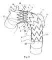
- FIG. 9illustrates a bifurcated stent graft.
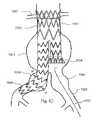
- FIG. 10illustrates the bifurcated stent graft implanted within an abdominal aortic aneurysm.
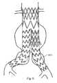
- FIG. 11illustrates the bifurcated stent graft having a branch extension implanted within an abdominal aortic aneurysm.
- FIG. 1illustrates an open stent member 1 formed from a single continuous wire and comprising multiple uneven undulations or sine waveforms of differing heights characterized by apexes or crests and troughs.
- the wireis formed in a tubular or ring-like configuration about a longitudinal axis.
- Apexes 11 , 12 , 13characterize the tubular configuration.
- the distal apexes 11 or troughs of the open stent member 1 forming the distal circumference of the open stentlie on the same plane approximately horizontal/perpendicular to the longitudinal axis 14 .
- the proximal apexes 12 , 13 or crestsare arranged along at least two different approximately horizontal/perpendicular to the longitudinal axis providing the undulations or waveforms with two or more different heights.
- the proximal apexes of the waveforms with the highest wave heights or of the undulations with the longest longitudinal lengths from the proximal apexes to the distal apexesare referred to as the high wave apexes 12 and the proximal apexes having the shortest longitudinal lengths are referred to as the short wave apexes 13 .
- all the proximal apexes of the same height or longitudinal lengthare arranged together and adjacent to one another. As illustrated in FIG. 1 , all the short wave apexes 13 are arranged together in adjacent turns.
- FIG. 2illustrates a mini-stent member 2 that is formed from a single continuous wire.
- the mini-wave stent membercomprises a wire having multiple uneven undulations or sine waveforms of differing heights characterized by apexes 21 , 22 , 23 or crests and troughs.
- the wireis formed in a tubular or ring-like configuration about a longitudinal axis 24 .
- the tubular configurationmay have a substantially uniform inner diameter or be conical in shape with a progressively smaller inner diameter from the proximal end to the distal end of the mini-stent member stent member.
- the distal apexes 21 or troughs of the mini-wave stent forming the distal circumference of the mini-wave stent 2lie on the same plane approximately horizontal/perpendicular to the longitudinal axis.
- the proximal apexes 22 , 23 or crestsare arranged along two different planes approximately horizontal/perpendicular to the longitudinal axis providing the undulations or waveforms with two different heights.
- the proximal apexes of the waveforms with the highest wave heights or of the undulations with the longest longitudinal lengths from the proximal apexes to the distal apexesshall be referred to as the high wave apexes 22 and the proximal apexes having the shortest longitudinal lengths shall be referred to as the short wave apexes 23 .
- the mini-wave stent memberis made of thinner wire with smaller undulations or wave heights and more undulations and apexes.
- the number of apexes in the mini-wave stent memberabout double the number of apexes found in the sloping stent member.
- FIG. 3illustrates a sloping stent member 3 that is formed from a single continuous wire.
- the sloping stent membercomprises a wire having multiple uneven undulations or sine waveforms of differing heights characterized by apexes 31 , 32 , 33 or crests and troughs.
- the wireis formed in a tubular or ring-like configuration about a longitudinal axis 34 .
- the tubular configurationmay have a substantially uniform inner diameter or be conical in shape with a progressively smaller inner diameter from the proximal end to the distal end of the sloping stent member.
- the distal apexes 31 or troughs of the sloping stent member forming the distal circumference of the sloping stent memberlie on the same plane approximately horizontal/perpendicular to the longitudinal axis.
- the proximal apexes or crestsare arranged in a sloping plane that is oblique to the longitudinal axis making the wave heights progressively shorter.
- the proximal apex 32 , 33 of the waveform with the highest wave height or of the undulation with the longest longitudinal length from the proximal apex to the distal apexshall be referred to as the high wave apex 32 and the proximal apex having the shortest longitudinal length shall be referred to as the short wave apex 33 .
- FIG. 4 , FIG. 5 and FIG. 6illustrate alternative configurations of apexes 102 , 103 , 104 in stent members 1 , 2 , & 3 .
- FIG. 4illustrates an apex 102 having a modified arcuate shape.
- the modified arcuate shapecomprises a stretched half circle 105 with straight segments 106 extending tangentially and vertically from the half circle. Angled segments 107 extend from the straight segments in an oblique manner to the vertical axis of the apex.
- FIG. 5illustrates an apex 103 having a coil shape.
- the wire of the apex 103is coiled to form a ring 108 having two angled segments 109 extending from the ring skewed to the vertical axis of the apex 103 .
- FIG. 6illustrates an apex 104 having modified arcuate shape with a coil.
- the wire of the apex 104is coiled to form a ring 110 having two straight segments 111 extending tangentially and vertically from the ring.
- Angled segments 112extend from the straight segments skewed to the vertical axis of the apex 103 .
- FIG. 7illustrates a tubular stent graft.
- the tubular stent graft 5comprises an open stent member 1 , a mini-wave stent member 2 and a plurality or sloping stent members 3 coupled in a series of successive neighboring instances from the proximal end to the distal end of the tubular graft member 4 .
- the stent membersmay be disposed about the outer diameter of the graft member, within the inner diameter of the graft member or within the wall of the graft member.
- the distal apexes 11 of the open stent member 1are coupled to the proximal end 41 of the tubular graft member 4 .
- the mini-wave stent member 2is coupled to the tubular graft member 4 with the high wave apex 22 positioned close to the proximal end 41 of the tubular graft member 4 and between the distal apexes 11 of the open stent member 1 .
- Multiple sloping stent members 3are coupled to the tubular graft member 4 in a series of adjacent to one another. The sloping stent members are spaced apart in a uniform manner.
- the short wave apexes of the sloping stent membersare arranged on the same radial side of the stent graft. This radial side is referred to as the flexible side 52 of the stent graft.
- the distance between proximal apexes of each stent member and its neighboring stent member on the flexible side of the stent graftis greater than the distances between the proximal apexes of neighboring stent members on the rigid side.
- the high wave apexes 32 of the sloping stent membersare positioned on the same radial side, which is called the rigid side 51 , aligned longitudinally with the short wave apex 13 of the open stent member 1 .
- a longitudinal bar 71connects the open stent member 1 and the distal most sloping stent member 72 on the rigid side 51 of the stent graft where the high wave apexes 32 of the sloping stent members 3 lie.
- Multiple radiopaque markersmay be disposed within the tubular graft member 5 .
- All stent membersincluding the open stent member 1 , the mini-wave stent member 2 and the sloping stent member 3 , are made of biocompatible material, such as nitinol, cobalt chrome alloys (e.g. Elgiloy), stainless steel and titanium/platinum/tungsten alloys.
- biocompatible materialsuch as nitinol, cobalt chrome alloys (e.g. Elgiloy), stainless steel and titanium/platinum/tungsten alloys.
- the graft member 4is made of a biocompatible material, such as expanded polytetrafluorethylene (ePTFE), polyester fabric, polypropylene, microporous urethane, hexafluoropropylene, polyfluorocarbon, Polyamide, polyethylene terephthalate, nylon, lycra, or other suitable biocompatible material, or alternatively a multilayer liner or compounding material made from one or one more materials.
- a biocompatible materialsuch as expanded polytetrafluorethylene (ePTFE), polyester fabric, polypropylene, microporous urethane, hexafluoropropylene, polyfluorocarbon, Polyamide, polyethylene terephthalate, nylon, lycra, or other suitable biocompatible material, or alternatively a multilayer liner or compounding material made from one or one more materials.
- FIG. 8illustrates the tubular stent graft 5 in use implanted within the aortic arch 7 .
- the stent graft 5Prior to deployment, the stent graft 5 is sterilized, disposed within a sheath of a delivery system and then transferred via a delivery system to the diseased area in the aortic arch 7 .
- the rigid side 51 where the connecting bar 71 liesis positioned towards the outward curve 72 of the arch 7
- the proximal end 41 of the graft member 4is positioned within the proximal aneurysm neck, close to the distal end of the port of the left subclavian artery 75 .
- the open stent member 1is deployed first.
- the short wave apexes 13are sized and dimensioned to avoid covering the branch port of the left normal carotid and the high wave apexes 12 are sized and dimensioned to contact the wall 74 of inward curve of the arch 7 before they overturn.
- the mini-wave stent member 2 and the sloping stent members 3expand and affix themselves to the wall of aorta 7 .
- the stent graft 5flexes within the arch 7 .
- the rigid side 51 of the stent graft 5maintains its longitudinal length, while the flexible side 52 shrinks in length because the soft graft member 4 between sloping stent members 3 retracts allowing the two neighboring stent members 3 to move closer.
- the mini-wave stent membercomprises more apexes 21 , 22 , 23 and undulations than the sloping stent members 3 .
- FIG. 9illustrates a bifurcated stent graft.
- the bifurcated stent graftcomprises an open stent member 1001 , two mini-wave stent members 1002 , 1005 , a plurality of sloping stent members 1004 and a plurality of uniform stent members 1003 coupled to a tubular bifurcated graft member 2001 .
- the bifurcated graft member 2001comprises a trunk graft portion 2001 and two branch portions extending from the distal end of the trunk graft portion.
- the first branch portion extending from the trunk portionis a long branch graft portion 2002 also referred to as an ipsilateral iliac branch graft portion.
- the second branch portionis a short branch graft portion 2003 which is referred to as a contralateral iliac branch graft portion.
- the short branch graft portion 2003further comprises an umbrella-like introducing graft portion 2004 disposed on its distal end.
- the introducing graft portion 2004is flared or frustoconical in shape having a larger distal outer diameter than the short branch graft portion 2003 .
- the distal apexes of the open stent member 1001are coupled to the proximal end of the trunk graft portion 2001 of the bifurcated tubular graft member.
- a mini-wave stent member 1002is fixed fully to the trunk graft portion 2001 with each high wave apex 22 positioned close to the proximal end of the trunk graft portion 2001 and between the distal apexes of the open stent member 1001 .
- One or more uniform stent members 1003are coupled to the trunk graft portion 2001 and to the short branch portion 2003 .
- a uniform stent membercomprises multiple even undulations and apexes defining a tubular configuration with the proximal apexes or crests lying in substantially the same plane and the distal apexes or troughs lying in substantially the same plane.
- the uniform stent memberhas a substantially uniform longitudinal distance or wave height along the uniform stent member.
- a plurality of sloping stent members 1004are coupled to the long branch graft member 2002 in adjacent instances.
- the sloping stent membersare uniformly spaced apart along the long branch graft portion 2002 .
- Each high wave apex 32is positioned on the same radial side close to the short branch graft portion 2003 .
- the distal end of each sloping stent member 1004is directed towards the distal end of the long branch graft portion 2002 .
- a longitudinal bar 91connects the proximal most sloping stent member 92 and the distal most sloping stent member 93 on the rigid side 94 which is the side closest to the short branch graft portion 2003 .
- One or more radiopaque markersmay be disposed within said tubular graft member 5 .
- the stent membersincluding the open stent member 1001 , the mini-wave stent member 1002 , 1005 , the normal stent members 1003 and the sloping stent member 1004 , are made of biocompatible material, such as, not limited to, nitinol, cobalt chrome alloys (e.g. Elgiloy), stainless steel or titanium/platinum/tungsten alloys.
- biocompatible materialsuch as, not limited to, nitinol, cobalt chrome alloys (e.g. Elgiloy), stainless steel or titanium/platinum/tungsten alloys.
- the bifurcated tubular graft member 2001is made of a biocompatible material, such as, not limited to, expanded polytetrafluorethylene (ePTFE), polyester fabric, polypropylene, microporous urethane, hexafluoropropylene, polyfluorocarbon, Polyamide, polyethylene terephthalate, nylon, lycra, or other suitable biocompatible material, or alternatively a multilayer liner or compounding material made of/from one or one more materials previously mentioned.
- ePTFEexpanded polytetrafluorethylene
- polyester fabricsuch as, not limited to, expanded polytetrafluorethylene (ePTFE), polyester fabric, polypropylene, microporous urethane, hexafluoropropylene, polyfluorocarbon, Polyamide, polyethylene terephthalate, nylon, lycra, or other suitable biocompatible material, or alternatively a multilayer liner or compounding material made of/from one or one more materials previously mentioned.
- ePTFEexpanded polyt
- FIG. 10illustrates the bifurcated stent graft implanted within an abdominal aortic aneurysm 7003 .
- the stent graftPrior to implantation, the stent graft is sterilized, disposed within a sheath of a delivery system and then delivered via the delivery system to the diseased area of the vessel in the abdominal aortic aneurysm 7003 .
- the proximal end of the trunk graft portion 2001is positioned within the proximal aneurysm neck 7002 and close to the distal end of the lower renal artery 7001 opening.
- the open stent member 1001is first deployed, covering the renal artery without cutting off the blood flow into the renal artery and facilitating the fixation of the stent graft to the vessel wall. While being deployed, the mini-wave stent member 1002 and the uniform stent member 1003 within the trunk graft portion 2001 expand and affixes the bifurcated stent graft to the neck of the vessel wall 7002 . The mini-wave stent member 1005 within the introducing graft portion 2004 expands within the sac of the aneurysm 7003 .
- the sloping stent members 1004 within the distal part of the long branch graft portion 2002expand accordingly and affix themselves to the common iliac artery 7005 .
- the sloping stent members 1004flex within the curved iliac artery.
- the space between the sloping stent members 1004retracts along the flexible side 95 of the long branch graft portion 2002 allowing neighboring stent members 1004 to move closer.
- the mini-wave stent member 1002comprises more apexes 21 , 22 , 23 and undulations than the uniform stent members 1003 .
- the mini-wave stent member 1002is more capable of forming to the irregular or deformed profile of the inner lumen of the aneurysm neck 7002 and affixing the stent graft to the vessel wall which will reducing the possibility of proximal endoleakage.
- the introducing graft portion 2004expands, it creates an inner diameter larger than the inner diameter of short graft portion 2003 forming a funnel or conical shape.
- the conical shape of the introducing graft portion 2004makes it comparatively easy to center and place the guide wire into the introducing graft portion 2004 .
- Once the guide wire is inside the introducing graft portion 2004it is easier to then place the guide wire within the short graft portion 2003 when the bifurcated stent graft is disposed within the large aneurysm sac 7003 .
- FIG. 11illustrates the bifurcated stent graft having a branch extension implanted within an abdominal aortic aneurysm.
- a branch extension 3001is placed within the iliac artery and coupled to the short branch portion.
- the bifurcated stent graft with the branch extensionisolates the diseased portion of the vessel containing the aneurysm from blood pressure within the vessel.
- bloodflows into the iliac arteries through the stent graft without bringing pressure on the vessel wall within the aneurysm sac.
Landscapes
- Health & Medical Sciences (AREA)
- Gastroenterology & Hepatology (AREA)
- Pulmonology (AREA)
- Cardiology (AREA)
- Oral & Maxillofacial Surgery (AREA)
- Transplantation (AREA)
- Engineering & Computer Science (AREA)
- Biomedical Technology (AREA)
- Heart & Thoracic Surgery (AREA)
- Vascular Medicine (AREA)
- Life Sciences & Earth Sciences (AREA)
- Animal Behavior & Ethology (AREA)
- General Health & Medical Sciences (AREA)
- Public Health (AREA)
- Veterinary Medicine (AREA)
- Prostheses (AREA)
Abstract
Description
Claims (33)
Applications Claiming Priority (4)
| Application Number | Priority Date | Filing Date | Title |
|---|---|---|---|
| CN200520041828 | 2005-05-24 | ||
| CN200520041828.8 | 2005-05-24 | ||
| CNU2005200418288UCN2817768Y (en) | 2005-05-24 | 2005-05-24 | Tectorium stand and host cage section thereof |
| PCT/CN2006/001068WO2006125382A1 (en) | 2005-05-24 | 2006-05-23 | Flexible stent-graft |
Related Child Applications (1)
| Application Number | Title | Priority Date | Filing Date |
|---|---|---|---|
| US13/272,868DivisionUS8726977B2 (en) | 2003-09-22 | 2011-10-13 | Pressure vessel assembly for integrated pressurized fluid system |
Publications (2)
| Publication Number | Publication Date |
|---|---|
| US20080195191A1 US20080195191A1 (en) | 2008-08-14 |
| US9056000B2true US9056000B2 (en) | 2015-06-16 |
Family
ID=37003820
Family Applications (1)
| Application Number | Title | Priority Date | Filing Date |
|---|---|---|---|
| US11/572,908Active2030-09-28US9056000B2 (en) | 2005-05-24 | 2006-05-23 | Flexible stent-graft |
Country Status (4)
| Country | Link |
|---|---|
| US (1) | US9056000B2 (en) |
| EP (1) | EP1888006B1 (en) |
| CN (1) | CN2817768Y (en) |
| WO (1) | WO2006125382A1 (en) |
Cited By (2)
| Publication number | Priority date | Publication date | Assignee | Title |
|---|---|---|---|---|
| US10888414B2 (en) | 2019-03-20 | 2021-01-12 | inQB8 Medical Technologies, LLC | Aortic dissection implant |
| US11471265B2 (en) | 2017-12-27 | 2022-10-18 | Lifetech Scientific (Shenzhen) Co. Ltd. | Covered stent |
Families Citing this family (85)
| Publication number | Priority date | Publication date | Assignee | Title |
|---|---|---|---|---|
| US7147661B2 (en) | 2001-12-20 | 2006-12-12 | Boston Scientific Santa Rosa Corp. | Radially expandable stent |
| US8292943B2 (en) | 2003-09-03 | 2012-10-23 | Bolton Medical, Inc. | Stent graft with longitudinal support member |
| US8500792B2 (en) | 2003-09-03 | 2013-08-06 | Bolton Medical, Inc. | Dual capture device for stent graft delivery system and method for capturing a stent graft |
| US11596537B2 (en) | 2003-09-03 | 2023-03-07 | Bolton Medical, Inc. | Delivery system and method for self-centering a proximal end of a stent graft |
| US20080264102A1 (en) | 2004-02-23 | 2008-10-30 | Bolton Medical, Inc. | Sheath Capture Device for Stent Graft Delivery System and Method for Operating Same |
| US20070198078A1 (en)* | 2003-09-03 | 2007-08-23 | Bolton Medical, Inc. | Delivery system and method for self-centering a Proximal end of a stent graft |
| US7763063B2 (en) | 2003-09-03 | 2010-07-27 | Bolton Medical, Inc. | Self-aligning stent graft delivery system, kit, and method |
| US9198786B2 (en) | 2003-09-03 | 2015-12-01 | Bolton Medical, Inc. | Lumen repair device with capture structure |
| US11259945B2 (en) | 2003-09-03 | 2022-03-01 | Bolton Medical, Inc. | Dual capture device for stent graft delivery system and method for capturing a stent graft |
| ATE461675T1 (en) | 2006-10-24 | 2010-04-15 | Cook Inc | STENT ELEMENT |
| JP4961517B2 (en)* | 2007-02-20 | 2012-06-27 | 国立大学法人福井大学 | Stent and therapeutic device for tubular organ using the same |
| CN101176686B (en)* | 2007-11-20 | 2010-06-02 | 微创医疗器械(上海)有限公司 | Tectorial bracket |
| US9180030B2 (en) | 2007-12-26 | 2015-11-10 | Cook Medical Technologies Llc | Low profile non-symmetrical stent |
| US9226813B2 (en) | 2007-12-26 | 2016-01-05 | Cook Medical Technologies Llc | Low profile non-symmetrical stent |
| US8574284B2 (en) | 2007-12-26 | 2013-11-05 | Cook Medical Technologies Llc | Low profile non-symmetrical bare alignment stents with graft |
| GB2476451A (en) | 2009-11-19 | 2011-06-29 | Cook William Europ | Stent Graft |
| CN102076281B (en) | 2008-06-30 | 2014-11-05 | 波顿医疗公司 | Systems and methods for abdominal aortic aneurysm |
| US8734502B2 (en)* | 2008-12-17 | 2014-05-27 | Cook Medical Technologies Llc | Tapered stent and flexible prosthesis |
| US8641753B2 (en) | 2009-01-31 | 2014-02-04 | Cook Medical Technologies Llc | Preform for and an endoluminal prosthesis |
| EP3284447B1 (en) | 2009-03-13 | 2020-05-20 | Bolton Medical Inc. | System for deploying an endoluminal prosthesis at a surgical site |
| CN101836911A (en)* | 2009-03-18 | 2010-09-22 | 微创医疗器械(上海)有限公司 | Collateral filmed stent |
| CA3009244C (en) | 2009-06-23 | 2020-04-28 | Endospan Ltd. | Vascular prostheses for treating aneurysms |
| WO2011004374A1 (en) | 2009-07-09 | 2011-01-13 | Endospan Ltd. | Apparatus for closure of a lumen and methods of using the same |
| US9757263B2 (en)* | 2009-11-18 | 2017-09-12 | Cook Medical Technologies Llc | Stent graft and introducer assembly |
| CN102740807B (en) | 2009-11-30 | 2015-11-25 | 恩多斯潘有限公司 | Multi-component stent-graft system for implantation into vessels with multiple branches |
| EP2506799A4 (en) | 2009-12-01 | 2014-10-29 | Altura Medical Inc | Modular endograft devices and associated systems and methods |
| EP2509535B1 (en) | 2009-12-08 | 2016-12-07 | Endospan Ltd | Endovascular stent-graft system with fenestrated and crossing stent-grafts |
| WO2011081814A1 (en) | 2009-12-28 | 2011-07-07 | Cook Medical Technologies Llc | Endoluminal device with kink-resistant regions |
| US9468517B2 (en) | 2010-02-08 | 2016-10-18 | Endospan Ltd. | Thermal energy application for prevention and management of endoleaks in stent-grafts |
| US20110208289A1 (en)* | 2010-02-25 | 2011-08-25 | Endospan Ltd. | Flexible Stent-Grafts |
| US20110218617A1 (en)* | 2010-03-02 | 2011-09-08 | Endologix, Inc. | Endoluminal vascular prosthesis |
| WO2012040240A1 (en) | 2010-09-20 | 2012-03-29 | Altura Medical, Inc. | Stent graft delivery systems and associated methods |
| CA2826022A1 (en) | 2011-02-03 | 2012-08-09 | Endospan Ltd. | Implantable medical devices constructed of shape memory material |
| WO2012111006A1 (en) | 2011-02-17 | 2012-08-23 | Endospan Ltd. | Vascular bands and delivery systems therefor |
| WO2012117395A1 (en) | 2011-03-02 | 2012-09-07 | Endospan Ltd. | Reduced-strain extra- vascular ring for treating aortic aneurysm |
| US8574287B2 (en) | 2011-06-14 | 2013-11-05 | Endospan Ltd. | Stents incorporating a plurality of strain-distribution locations |
| US8951298B2 (en) | 2011-06-21 | 2015-02-10 | Endospan Ltd. | Endovascular system with circumferentially-overlapping stent-grafts |
| AU2012203620B9 (en) | 2011-06-24 | 2014-10-02 | Cook Medical Technologies Llc | Helical Stent |
| US9254209B2 (en) | 2011-07-07 | 2016-02-09 | Endospan Ltd. | Stent fixation with reduced plastic deformation |
| US9839510B2 (en) | 2011-08-28 | 2017-12-12 | Endospan Ltd. | Stent-grafts with post-deployment variable radial displacement |
| US9427339B2 (en) | 2011-10-30 | 2016-08-30 | Endospan Ltd. | Triple-collar stent-graft |
| US9597204B2 (en) | 2011-12-04 | 2017-03-21 | Endospan Ltd. | Branched stent-graft system |
| EP2846743B1 (en) | 2012-04-12 | 2016-12-14 | Bolton Medical Inc. | Vascular prosthetic delivery device |
| US9737394B2 (en)* | 2012-04-27 | 2017-08-22 | Medtronic Vascular, Inc. | Stent-graft prosthesis for placement in the abdominal aorta |
| WO2013171730A1 (en) | 2012-05-15 | 2013-11-21 | Endospan Ltd. | Stent-graft with fixation elements that are radially confined for delivery |
| CA2881535A1 (en) | 2012-08-10 | 2014-02-13 | Altura Medical, Inc. | Stent delivery systems and associated methods |
| DE102012111225A1 (en) | 2012-11-21 | 2014-05-22 | Jotec Gmbh | Vascular implant with lateral branch |
| DE102012111223A1 (en)* | 2012-11-21 | 2014-05-22 | Jotec Gmbh | Vascular implant with asymmetric stent springs |
| US9668892B2 (en) | 2013-03-11 | 2017-06-06 | Endospan Ltd. | Multi-component stent-graft system for aortic dissections |
| US9439751B2 (en) | 2013-03-15 | 2016-09-13 | Bolton Medical, Inc. | Hemostasis valve and delivery systems |
| WO2014144809A1 (en) | 2013-03-15 | 2014-09-18 | Altura Medical, Inc. | Endograft device delivery systems and associated methods |
| CN104586537B (en)* | 2013-10-31 | 2017-05-10 | 微创心脉医疗科技(上海)有限公司 | Covered stent |
| CN104586536B (en)* | 2013-10-31 | 2017-05-03 | 微创心脉医疗科技(上海)有限公司 | Covered stent |
| WO2015075708A1 (en) | 2013-11-19 | 2015-05-28 | Endospan Ltd. | Stent system with radial-expansion locking |
| CN103598929B (en)* | 2013-11-28 | 2016-04-20 | 先健科技(深圳)有限公司 | Thoracic aorta covered bracket |
| CN104434352B (en)* | 2014-12-14 | 2016-08-17 | 韩新巍 | A kind of compliance recyclable air flue mushroom covered stent and preparation method thereof |
| CN106029005B (en) | 2014-12-18 | 2018-01-19 | 恩都思潘有限公司 | The Endovascular stent-graft of horizontal conduit with tired resistance |
| WO2016113731A1 (en) | 2015-01-12 | 2016-07-21 | Endospan Ltd. | Self-curving stent-graft |
| CN105030373A (en)* | 2015-09-07 | 2015-11-11 | 湖南埃普特医疗器械有限公司 | Aorta covered stent |
| WO2017047569A1 (en)* | 2015-09-18 | 2017-03-23 | 川澄化学工業株式会社 | Stent and stent-graft |
| WO2017081679A1 (en) | 2015-11-12 | 2017-05-18 | Endospan Ltd. | Stent-grafts systems with skirt |
| CN106175981A (en)* | 2016-03-04 | 2016-12-07 | 上海沐春投资管理有限公司 | A kind of part band film intravenous type support |
| CN108013955B (en)* | 2016-11-04 | 2020-01-10 | 先健科技(深圳)有限公司 | Blood vessel support |
| CN109549756B (en)* | 2017-09-25 | 2021-05-07 | 先健科技(深圳)有限公司 | Heart valve |
| CN109966017B (en)* | 2017-12-27 | 2021-08-27 | 先健科技(深圳)有限公司 | Covered stent |
| CN109966015B (en)* | 2017-12-27 | 2023-04-18 | 先健科技(深圳)有限公司 | Covered stent |
| CN109966016B (en)* | 2017-12-27 | 2021-02-23 | 先健科技(深圳)有限公司 | Covered stent |
| JP6698262B2 (en)* | 2018-03-09 | 2020-05-27 | 日本ライフライン株式会社 | Aortic treatment device |
| CN109431650B (en)* | 2018-11-27 | 2021-08-17 | 深圳市先健畅通医疗有限公司 | Covered stent |
| CN109464212B (en)* | 2018-12-14 | 2022-04-05 | 深圳市先健畅通医疗有限公司 | Covered stent |
| CN111374810B (en)* | 2018-12-29 | 2025-03-07 | 杭州唯强医疗科技有限公司 | A coated vascular stent with improved wall adhesion performance |
| CN112823766B (en)* | 2019-11-21 | 2022-12-20 | 深圳市先健畅通医疗有限公司 | Double-layer lumen stent |
| EP4585192A3 (en) | 2020-06-24 | 2025-10-15 | Bolton Medical, Inc. | Anti-backspin component for vascular prosthesis delivery device |
| EP4180006A4 (en)* | 2020-07-07 | 2024-07-31 | Hiroshima University | Stent graft |
| EP4180005A4 (en)* | 2020-07-07 | 2024-07-31 | Hiroshima University | Stent graft |
| CN114652486A (en)* | 2020-12-23 | 2022-06-24 | 深圳市先健畅通医疗有限公司 | Covered stent |
| CN112773585B (en)* | 2020-12-30 | 2023-11-14 | 杭州唯强医疗科技有限公司 | Implantation of stents |
| CN112773584B (en)* | 2020-12-30 | 2024-03-19 | 杭州唯强医疗科技有限公司 | Implant holder |
| WO2022227283A1 (en)* | 2021-04-30 | 2022-11-03 | 光华临港工程应用技术研发(上海)有限公司 | Aortic covered stent |
| CN113679936B (en)* | 2021-10-27 | 2022-04-01 | 上海微创医疗器械(集团)有限公司 | Degradable drug stent system |
| CN113876467B (en)* | 2021-12-08 | 2022-04-15 | 上海微创心脉医疗科技(集团)股份有限公司 | stent graft |
| WO2023124903A1 (en)* | 2021-12-31 | 2023-07-06 | 先健科技(深圳)有限公司 | Endoluminal stent |
| CN114617683A (en)* | 2022-05-17 | 2022-06-14 | 上海微创心脉医疗科技(集团)股份有限公司 | Medical support |
| CN116965993B (en)* | 2023-09-25 | 2024-01-19 | 北京华脉泰科医疗器械股份有限公司 | Tectorial membrane support |
| CN120346025B (en)* | 2025-06-24 | 2025-09-19 | 浙江归创医疗科技有限公司 | Tectorial membrane bracket and preparation method thereof |
Citations (51)
| Publication number | Priority date | Publication date | Assignee | Title |
|---|---|---|---|---|
| US5800515A (en)* | 1995-08-03 | 1998-09-01 | B. Braun Celsa (Societe Anonyme) | Prosthesis implantable in a human or animal duct such as a stent or a prosthesis for aneurism |
| US6027525A (en)* | 1996-05-23 | 2000-02-22 | Samsung Electronics., Ltd. | Flexible self-expandable stent and method for making the same |
| US20020091439A1 (en)* | 1994-12-15 | 2002-07-11 | Baker Steve G. | Graft assembly having support structure |
| US20020177890A1 (en)* | 1996-01-05 | 2002-11-28 | Lenker Jay A. | Stent graft loading and deployment device and method |
| US20030181969A1 (en)* | 1999-12-03 | 2003-09-25 | Kugler Chad J. | Endovascular graft system |
| US6648913B1 (en)* | 1999-06-07 | 2003-11-18 | Scimed Life Systems, Inc. | Guidewire-access modular intraluminal prosthesis with connecting section |
| US6673107B1 (en)* | 1999-12-06 | 2004-01-06 | Advanced Cardiovascular Systems, Inc. | Bifurcated stent and method of making |
| US20040034402A1 (en)* | 2002-07-26 | 2004-02-19 | Syntheon, Llc | Helical stent having flexible transition zone |
| US20040193245A1 (en)* | 2003-03-26 | 2004-09-30 | The Foundry, Inc. | Devices and methods for treatment of abdominal aortic aneurysm |
| US20040215326A1 (en)* | 2003-04-22 | 2004-10-28 | Goodson Harry B. | Single-piece crown stent |
| US20040215319A1 (en)* | 2003-04-24 | 2004-10-28 | Humberto Berra | Stent graft tapered spring |
| US20050033410A1 (en)* | 2002-12-24 | 2005-02-10 | Novostent Corporation | Vascular prothesis having flexible configuration |
| US20050154448A1 (en)* | 1999-01-22 | 2005-07-14 | Gore Enterprise Holdings, Inc. | Biliary stent-graft |
| US20050228484A1 (en)* | 2004-03-11 | 2005-10-13 | Trivascular, Inc. | Modular endovascular graft |
| US20050278017A1 (en)* | 2004-06-09 | 2005-12-15 | Scimed Life Systems, Inc. | Overlapped stents for scaffolding, flexibility and MRI compatibility |
| US20060004436A1 (en)* | 2004-07-02 | 2006-01-05 | Amarant Paul D | Stent having arcuate struts |
| US20060030926A1 (en)* | 2004-07-20 | 2006-02-09 | Medtronic Vascular, Inc. | Endoluminal prosthesis having expandable graft sections |
| US7004968B2 (en)* | 2002-12-20 | 2006-02-28 | Biotronik Gmbh & Co. Kg | Stent |
| US20060178733A1 (en)* | 2005-01-21 | 2006-08-10 | Leonard Pinchuk | Modular stent graft employing bifurcated graft and leg locking stent elements |
| US20060195172A1 (en)* | 2004-08-17 | 2006-08-31 | Microport Medical Co., Ltd. | Multi-unit stent-graft |
| US20070055345A1 (en)* | 2005-09-02 | 2007-03-08 | Medtronic Vascular, Inc. | Endoluminal prosthesis |
| US20070088428A1 (en)* | 2005-09-15 | 2007-04-19 | Cappella, Inc. | Intraluminal device with asymmetric cap portion |
| US20070135889A1 (en)* | 2003-09-03 | 2007-06-14 | Bolton Medical, Inc. | Lumen repair device with capture structure |
| US20070225797A1 (en)* | 2006-03-24 | 2007-09-27 | Medtronic Vascular, Inc. | Prosthesis With Adjustable Opening for Side Branch Access |
| US20070233220A1 (en)* | 2006-03-30 | 2007-10-04 | Medtronic Vascular, Inc. | Prosthesis With Guide Lumen |
| US20080114443A1 (en)* | 2006-11-14 | 2008-05-15 | Medtronic Vascular, Inc. | Stent-Graft With Anchoring Pins |
| US20080114441A1 (en)* | 2006-11-14 | 2008-05-15 | Medtronic Vascular, Inc. | Endoluminal Prosthesis |
| US20080319535A1 (en)* | 2007-06-25 | 2008-12-25 | Medtronic Vascular, Inc. | Vascular Stent and Method of Making Vascular Stent |
| US20090082846A1 (en)* | 2007-09-26 | 2009-03-26 | Boston Scientific Corporation | Asymmetric stent apparatus and method |
| US20100152835A1 (en)* | 2008-12-17 | 2010-06-17 | Med Institute, Inc. | Tapered Stent and Flexible Prosthesis |
| US20110022149A1 (en)* | 2007-06-04 | 2011-01-27 | Cox Brian J | Methods and devices for treatment of vascular defects |
| US20110087318A1 (en)* | 2009-10-09 | 2011-04-14 | Daugherty John R | Bifurcated highly conformable medical device branch access |
| US20110166644A1 (en)* | 2008-02-22 | 2011-07-07 | Barts and The Londhon NHS Trust | Blood vessel prosthesis and delivery apparatus |
| US20110218609A1 (en)* | 2010-02-10 | 2011-09-08 | Trivascular, Inc. | Fill tube manifold and delivery methods for endovascular graft |
| US20120059452A1 (en)* | 2006-01-24 | 2012-03-08 | Boucher Donald D | Percutaneous endoprosthesis using suprarenal fixation and barbed anchors |
| US8163006B2 (en)* | 2004-07-28 | 2012-04-24 | Cordis Corporation | Reduced profile AAA device |
| US20120130478A1 (en)* | 2010-11-16 | 2012-05-24 | Shaw Edward E | Devices and methods for in situ fenestration of a stent-graft at the site of a branch vessel |
| US8226703B2 (en)* | 2008-02-29 | 2012-07-24 | Cordis Corporation | Method and device for attaching a stent structure to AAA graft material |
| US20120259404A1 (en)* | 2010-12-13 | 2012-10-11 | Microvention, Inc. | Stent |
| US8425585B2 (en)* | 2006-10-24 | 2013-04-23 | Cook Medical Technologies Llc | Thoracic arch stent graft and method of delivery |
| US20130131780A1 (en)* | 2011-01-14 | 2013-05-23 | W. L. Gore & Associates, Inc. | Lattice |
| US20130144373A1 (en)* | 2011-12-06 | 2013-06-06 | Aortic Innovations Llc | Device for endovascular aortic repair and method of using the same |
| US20130166010A1 (en)* | 2011-12-23 | 2013-06-27 | Cook Medical Technologies Llc | Hybrid balloon-expandable/self-expanding prosthesis for deployment in a body vessel and method of making |
| US20130245745A1 (en)* | 2012-03-16 | 2013-09-19 | Microvention, Inc. | Stent and stent delivery device |
| US8623065B2 (en)* | 1994-08-31 | 2014-01-07 | W. L. Gore & Associates, Inc. | Exterior supported self-expanding stent-graft |
| US8641753B2 (en)* | 2009-01-31 | 2014-02-04 | Cook Medical Technologies Llc | Preform for and an endoluminal prosthesis |
| US20140088678A1 (en)* | 2012-09-27 | 2014-03-27 | John Wainwright | Vascular stent with improved vessel wall apposition |
| US8709068B2 (en)* | 2007-03-05 | 2014-04-29 | Endospan Ltd. | Multi-component bifurcated stent-graft systems |
| US8728145B2 (en)* | 2008-12-11 | 2014-05-20 | Cook Medical Technologies Llc | Low profile non-symmetrical stents and stent-grafts |
| US8728148B2 (en)* | 2011-11-09 | 2014-05-20 | Cook Medical Technologies Llc | Diameter reducing tie arrangement for endoluminal prosthesis |
| US20140248418A1 (en)* | 2011-01-28 | 2014-09-04 | Merit Medical Systems, Inc. | Electrospun ptfe coated stent and method of use |
Family Cites Families (5)
| Publication number | Priority date | Publication date | Assignee | Title |
|---|---|---|---|---|
| US6733523B2 (en)* | 1998-12-11 | 2004-05-11 | Endologix, Inc. | Implantable vascular graft |
| JP2003533335A (en)* | 2000-05-22 | 2003-11-11 | オーバス メディカル テクノロジーズ インク. | Self-expanding stent |
| CN2635119Y (en) | 2003-07-25 | 2004-08-25 | 微创医疗器械(上海)有限公司 | Artificial blood vessel having support |
| US7144421B2 (en)* | 2003-11-06 | 2006-12-05 | Carpenter Judith T | Endovascular prosthesis, system and method |
| CN2675083Y (en)* | 2004-01-06 | 2005-02-02 | 微创医疗器械(上海)有限公司 | Stent graft for |
- 2005
- 2005-05-24CNCNU2005200418288Upatent/CN2817768Y/ennot_activeExpired - Lifetime
- 2006
- 2006-05-23EPEP06741956.4Apatent/EP1888006B1/enactiveActive
- 2006-05-23USUS11/572,908patent/US9056000B2/enactiveActive
- 2006-05-23WOPCT/CN2006/001068patent/WO2006125382A1/enactiveSearch and Examination
Patent Citations (55)
| Publication number | Priority date | Publication date | Assignee | Title |
|---|---|---|---|---|
| US8623065B2 (en)* | 1994-08-31 | 2014-01-07 | W. L. Gore & Associates, Inc. | Exterior supported self-expanding stent-graft |
| US20020091439A1 (en)* | 1994-12-15 | 2002-07-11 | Baker Steve G. | Graft assembly having support structure |
| US5800515A (en)* | 1995-08-03 | 1998-09-01 | B. Braun Celsa (Societe Anonyme) | Prosthesis implantable in a human or animal duct such as a stent or a prosthesis for aneurism |
| US20020177890A1 (en)* | 1996-01-05 | 2002-11-28 | Lenker Jay A. | Stent graft loading and deployment device and method |
| US6027525A (en)* | 1996-05-23 | 2000-02-22 | Samsung Electronics., Ltd. | Flexible self-expandable stent and method for making the same |
| US20050154448A1 (en)* | 1999-01-22 | 2005-07-14 | Gore Enterprise Holdings, Inc. | Biliary stent-graft |
| US6648913B1 (en)* | 1999-06-07 | 2003-11-18 | Scimed Life Systems, Inc. | Guidewire-access modular intraluminal prosthesis with connecting section |
| US20030181969A1 (en)* | 1999-12-03 | 2003-09-25 | Kugler Chad J. | Endovascular graft system |
| US6673107B1 (en)* | 1999-12-06 | 2004-01-06 | Advanced Cardiovascular Systems, Inc. | Bifurcated stent and method of making |
| US20040034402A1 (en)* | 2002-07-26 | 2004-02-19 | Syntheon, Llc | Helical stent having flexible transition zone |
| US7004968B2 (en)* | 2002-12-20 | 2006-02-28 | Biotronik Gmbh & Co. Kg | Stent |
| US20050033410A1 (en)* | 2002-12-24 | 2005-02-10 | Novostent Corporation | Vascular prothesis having flexible configuration |
| US20040193245A1 (en)* | 2003-03-26 | 2004-09-30 | The Foundry, Inc. | Devices and methods for treatment of abdominal aortic aneurysm |
| US20040215326A1 (en)* | 2003-04-22 | 2004-10-28 | Goodson Harry B. | Single-piece crown stent |
| US6945992B2 (en)* | 2003-04-22 | 2005-09-20 | Medtronic Vascular, Inc. | Single-piece crown stent |
| US20040215319A1 (en)* | 2003-04-24 | 2004-10-28 | Humberto Berra | Stent graft tapered spring |
| US20070135889A1 (en)* | 2003-09-03 | 2007-06-14 | Bolton Medical, Inc. | Lumen repair device with capture structure |
| US20050228484A1 (en)* | 2004-03-11 | 2005-10-13 | Trivascular, Inc. | Modular endovascular graft |
| US20050278017A1 (en)* | 2004-06-09 | 2005-12-15 | Scimed Life Systems, Inc. | Overlapped stents for scaffolding, flexibility and MRI compatibility |
| US20060004436A1 (en)* | 2004-07-02 | 2006-01-05 | Amarant Paul D | Stent having arcuate struts |
| US20060030926A1 (en)* | 2004-07-20 | 2006-02-09 | Medtronic Vascular, Inc. | Endoluminal prosthesis having expandable graft sections |
| US8163006B2 (en)* | 2004-07-28 | 2012-04-24 | Cordis Corporation | Reduced profile AAA device |
| US20060195172A1 (en)* | 2004-08-17 | 2006-08-31 | Microport Medical Co., Ltd. | Multi-unit stent-graft |
| US20060178733A1 (en)* | 2005-01-21 | 2006-08-10 | Leonard Pinchuk | Modular stent graft employing bifurcated graft and leg locking stent elements |
| US8702787B2 (en)* | 2005-09-02 | 2014-04-22 | Medtronic Vascular, Inc. | Endoluminal prosthesis |
| US20070055345A1 (en)* | 2005-09-02 | 2007-03-08 | Medtronic Vascular, Inc. | Endoluminal prosthesis |
| US20070088428A1 (en)* | 2005-09-15 | 2007-04-19 | Cappella, Inc. | Intraluminal device with asymmetric cap portion |
| US20120059452A1 (en)* | 2006-01-24 | 2012-03-08 | Boucher Donald D | Percutaneous endoprosthesis using suprarenal fixation and barbed anchors |
| US20070225797A1 (en)* | 2006-03-24 | 2007-09-27 | Medtronic Vascular, Inc. | Prosthesis With Adjustable Opening for Side Branch Access |
| US20070233220A1 (en)* | 2006-03-30 | 2007-10-04 | Medtronic Vascular, Inc. | Prosthesis With Guide Lumen |
| US8425585B2 (en)* | 2006-10-24 | 2013-04-23 | Cook Medical Technologies Llc | Thoracic arch stent graft and method of delivery |
| US20080114443A1 (en)* | 2006-11-14 | 2008-05-15 | Medtronic Vascular, Inc. | Stent-Graft With Anchoring Pins |
| US7615072B2 (en)* | 2006-11-14 | 2009-11-10 | Medtronic Vascular, Inc. | Endoluminal prosthesis |
| US20080114441A1 (en)* | 2006-11-14 | 2008-05-15 | Medtronic Vascular, Inc. | Endoluminal Prosthesis |
| US8709068B2 (en)* | 2007-03-05 | 2014-04-29 | Endospan Ltd. | Multi-component bifurcated stent-graft systems |
| US20110022149A1 (en)* | 2007-06-04 | 2011-01-27 | Cox Brian J | Methods and devices for treatment of vascular defects |
| US20080319535A1 (en)* | 2007-06-25 | 2008-12-25 | Medtronic Vascular, Inc. | Vascular Stent and Method of Making Vascular Stent |
| US8663309B2 (en)* | 2007-09-26 | 2014-03-04 | Trivascular, Inc. | Asymmetric stent apparatus and method |
| US20090082846A1 (en)* | 2007-09-26 | 2009-03-26 | Boston Scientific Corporation | Asymmetric stent apparatus and method |
| US20110166644A1 (en)* | 2008-02-22 | 2011-07-07 | Barts and The Londhon NHS Trust | Blood vessel prosthesis and delivery apparatus |
| US8226703B2 (en)* | 2008-02-29 | 2012-07-24 | Cordis Corporation | Method and device for attaching a stent structure to AAA graft material |
| US8728145B2 (en)* | 2008-12-11 | 2014-05-20 | Cook Medical Technologies Llc | Low profile non-symmetrical stents and stent-grafts |
| US20100152835A1 (en)* | 2008-12-17 | 2010-06-17 | Med Institute, Inc. | Tapered Stent and Flexible Prosthesis |
| US8641753B2 (en)* | 2009-01-31 | 2014-02-04 | Cook Medical Technologies Llc | Preform for and an endoluminal prosthesis |
| US20110087318A1 (en)* | 2009-10-09 | 2011-04-14 | Daugherty John R | Bifurcated highly conformable medical device branch access |
| US20110218609A1 (en)* | 2010-02-10 | 2011-09-08 | Trivascular, Inc. | Fill tube manifold and delivery methods for endovascular graft |
| US20120130478A1 (en)* | 2010-11-16 | 2012-05-24 | Shaw Edward E | Devices and methods for in situ fenestration of a stent-graft at the site of a branch vessel |
| US20120259404A1 (en)* | 2010-12-13 | 2012-10-11 | Microvention, Inc. | Stent |
| US20130131780A1 (en)* | 2011-01-14 | 2013-05-23 | W. L. Gore & Associates, Inc. | Lattice |
| US20140248418A1 (en)* | 2011-01-28 | 2014-09-04 | Merit Medical Systems, Inc. | Electrospun ptfe coated stent and method of use |
| US8728148B2 (en)* | 2011-11-09 | 2014-05-20 | Cook Medical Technologies Llc | Diameter reducing tie arrangement for endoluminal prosthesis |
| US20130144373A1 (en)* | 2011-12-06 | 2013-06-06 | Aortic Innovations Llc | Device for endovascular aortic repair and method of using the same |
| US20130166010A1 (en)* | 2011-12-23 | 2013-06-27 | Cook Medical Technologies Llc | Hybrid balloon-expandable/self-expanding prosthesis for deployment in a body vessel and method of making |
| US20130245745A1 (en)* | 2012-03-16 | 2013-09-19 | Microvention, Inc. | Stent and stent delivery device |
| US20140088678A1 (en)* | 2012-09-27 | 2014-03-27 | John Wainwright | Vascular stent with improved vessel wall apposition |
Cited By (2)
| Publication number | Priority date | Publication date | Assignee | Title |
|---|---|---|---|---|
| US11471265B2 (en) | 2017-12-27 | 2022-10-18 | Lifetech Scientific (Shenzhen) Co. Ltd. | Covered stent |
| US10888414B2 (en) | 2019-03-20 | 2021-01-12 | inQB8 Medical Technologies, LLC | Aortic dissection implant |
Also Published As
| Publication number | Publication date |
|---|---|
| EP1888006A4 (en) | 2015-07-15 |
| US20080195191A1 (en) | 2008-08-14 |
| WO2006125382A1 (en) | 2006-11-30 |
| EP1888006B1 (en) | 2017-11-15 |
| EP1888006A1 (en) | 2008-02-20 |
| CN2817768Y (en) | 2006-09-20 |
Similar Documents
| Publication | Publication Date | Title |
|---|---|---|
| US9056000B2 (en) | Flexible stent-graft | |
| US6878164B2 (en) | Short body endoprosthesis | |
| JP6110427B2 (en) | System and method for sealing an anatomical opening | |
| JP5574123B2 (en) | Thoracic aortic stent graft with access region | |
| JP4076235B2 (en) | Modular body cavity prosthesis | |
| US9107670B2 (en) | Implant, especially for the occlusion of bifurcation aneurysms | |
| EP1750619B1 (en) | Flexible vascular occluding device | |
| US6015431A (en) | Endolumenal stent-graft with leak-resistant seal | |
| US6699277B1 (en) | Stent with cover connectors | |
| CN102143723B (en) | Thin-film implants for treating brain aneurysms | |
| EP1517651B1 (en) | Thoracic aortic aneurysm stent graft | |
| US20170360553A1 (en) | Intravascular implants and methods of using the same | |
| US20160324625A1 (en) | Surgical implant devices and methods for their manufacture and use | |
| US20030204246A1 (en) | Aneurysm treatment system and method | |
| US20010053930A1 (en) | Endovascular graft system | |
| US20040215324A1 (en) | Stent assembly | |
| JP2003230632A (en) | Prosthesis | |
| JP2006522618A (en) | Lumen device with enhanced mounting characteristics | |
| EP3917461A2 (en) | Expandable luminal stents and methods of use | |
| JP2003245292A (en) | Both-sided stretching prosthesis and distribution method | |
| JP2007523694A (en) | Prosthesis system and method sized and configured for receiving and holding fasteners | |
| JP2013507231A (en) | Paraplegia preventive stent graft | |
| JP2013543416A (en) | Stent graft system | |
| EP1800620B1 (en) | prosthesis comprising a coiled stent |
Legal Events
| Date | Code | Title | Description |
|---|---|---|---|
| AS | Assignment | Owner name:MICROPORT MEDICAL (SHANGHAI) CO., LTD., CHINA Free format text:ASSIGNMENT OF ASSIGNORS INTEREST;ASSIGNORS:LUO, QIYI;NIE, HONGLIN;ZHU, QING;AND OTHERS;REEL/FRAME:020148/0894 Effective date:20070226 | |
| AS | Assignment | Owner name:MICROPORT ENDOVASCULAR (SHANGHAI) CO., LTD., CHINA Free format text:ASSIGNMENT OF ASSIGNORS INTEREST;ASSIGNOR:SHANGHAI MICROPORT MEDICAL (GROUP) CO., LTD.;REEL/FRAME:035620/0757 Effective date:20150429 Owner name:SHANGHAI MICROPORT MEDICAL (GROUP) CO., LTD., CHIN Free format text:CHANGE OF NAME;ASSIGNOR:MICROPORT MEDICAL (SHANGHAI) CO., LTD.;REEL/FRAME:035649/0130 Effective date:20150212 | |
| STCF | Information on status: patent grant | Free format text:PATENTED CASE | |
| FEPP | Fee payment procedure | Free format text:PAYOR NUMBER ASSIGNED (ORIGINAL EVENT CODE: ASPN); ENTITY STATUS OF PATENT OWNER: LARGE ENTITY | |
| MAFP | Maintenance fee payment | Free format text:PAYMENT OF MAINTENANCE FEE, 4TH YEAR, LARGE ENTITY (ORIGINAL EVENT CODE: M1551); ENTITY STATUS OF PATENT OWNER: LARGE ENTITY Year of fee payment:4 | |
| AS | Assignment | Owner name:SHANGHAI MICROPORT ENDOVASCULAR MEDTECH CO., LTD., Free format text:CHANGE OF NAME;ASSIGNOR:MICROPORT ENDOVASCULAR (SHANGHAI) CO., LTD.;REEL/FRAME:049104/0917 Effective date:20180816 | |
| MAFP | Maintenance fee payment | Free format text:PAYMENT OF MAINTENANCE FEE, 8TH YEAR, LARGE ENTITY (ORIGINAL EVENT CODE: M1552); ENTITY STATUS OF PATENT OWNER: LARGE ENTITY Year of fee payment:8 |