US9055930B2 - Device for preparing an implanted medical apparatus for extraction - Google Patents
Device for preparing an implanted medical apparatus for extractionDownload PDFInfo
- Publication number
- US9055930B2 US9055930B2US13/716,975US201213716975AUS9055930B2US 9055930 B2US9055930 B2US 9055930B2US 201213716975 AUS201213716975 AUS 201213716975AUS 9055930 B2US9055930 B2US 9055930B2
- Authority
- US
- United States
- Prior art keywords
- lead
- handle
- wire
- wire member
- implanted
- Prior art date
- Legal status (The legal status is an assumption and is not a legal conclusion. Google has not performed a legal analysis and makes no representation as to the accuracy of the status listed.)
- Active, expires
Links
Images


Classifications
- A—HUMAN NECESSITIES
- A61—MEDICAL OR VETERINARY SCIENCE; HYGIENE
- A61N—ELECTROTHERAPY; MAGNETOTHERAPY; RADIATION THERAPY; ULTRASOUND THERAPY
- A61N1/00—Electrotherapy; Circuits therefor
- A61N1/02—Details
- A61N1/04—Electrodes
- A61N1/0404—Electrodes for external use
- A61N1/0472—Structure-related aspects
- A61N1/0488—Details about the lead
- A—HUMAN NECESSITIES
- A61—MEDICAL OR VETERINARY SCIENCE; HYGIENE
- A61B—DIAGNOSIS; SURGERY; IDENTIFICATION
- A61B17/00—Surgical instruments, devices or methods
- A—HUMAN NECESSITIES
- A61—MEDICAL OR VETERINARY SCIENCE; HYGIENE
- A61B—DIAGNOSIS; SURGERY; IDENTIFICATION
- A61B17/00—Surgical instruments, devices or methods
- A61B17/50—Instruments, other than pincettes or toothpicks, for removing foreign bodies from the human body
- A—HUMAN NECESSITIES
- A61—MEDICAL OR VETERINARY SCIENCE; HYGIENE
- A61N—ELECTROTHERAPY; MAGNETOTHERAPY; RADIATION THERAPY; ULTRASOUND THERAPY
- A61N1/00—Electrotherapy; Circuits therefor
- A61N1/02—Details
- A61N1/04—Electrodes
- A61N1/05—Electrodes for implantation or insertion into the body, e.g. heart electrode
- A61N1/056—Transvascular endocardial electrode systems
- A—HUMAN NECESSITIES
- A61—MEDICAL OR VETERINARY SCIENCE; HYGIENE
- A61B—DIAGNOSIS; SURGERY; IDENTIFICATION
- A61B17/00—Surgical instruments, devices or methods
- A61B2017/0046—Surgical instruments, devices or methods with a releasable handle; with handle and operating part separable
- A61B2017/00469—Surgical instruments, devices or methods with a releasable handle; with handle and operating part separable for insertion of instruments, e.g. guide wire, optical fibre
- A—HUMAN NECESSITIES
- A61—MEDICAL OR VETERINARY SCIENCE; HYGIENE
- A61N—ELECTROTHERAPY; MAGNETOTHERAPY; RADIATION THERAPY; ULTRASOUND THERAPY
- A61N1/00—Electrotherapy; Circuits therefor
- A61N1/02—Details
- A61N1/04—Electrodes
- A61N1/05—Electrodes for implantation or insertion into the body, e.g. heart electrode
- A61N1/056—Transvascular endocardial electrode systems
- A61N1/057—Anchoring means; Means for fixing the head inside the heart
- A61N2001/0578—Anchoring means; Means for fixing the head inside the heart having means for removal or extraction
Definitions
- This inventionrelates to a device for facilitating the extraction of an implanted medical apparatus from the body of a patient. More particularly, the invention relates to a device for preparing an implanted elongated medical apparatus for extraction from a body passageway by exerting a compressive force along the proximal end of the elongated apparatus to hold the elements of the apparatus in place during the extraction procedure.
- a variety of medical treatments and surgical methodsentail implanting a device, such as a pacemaker, in the body of a patient.
- a pacemakeris typically positioned in a subcutaneous tissue pocket in the chest wall of a patient.
- a pacemaker leadis implanted in the body of the patient to extend from the pacemaker through a vein into a chamber of the patient's heart.
- the leadcomprises an elongated apparatus that includes one or more longitudinal cables, wires, coils, etc. (hereafter collectively referred to as “cables”) encased within an elongated insulating body along the length of the lead.
- Some cablesmay conduct electrical signals (such as stimulating and/or sensing signals) between the pacemaker and the heart.
- Other cablesmay provide strength and/or support to the lead.
- the cablesmay extend the entire length of the lead, or a segment of that length.
- the elongated insulating bodygenerally formed of silicone or a polymer such as polyurethane, serves to simultaneously protect the cables from body fluids, and insulate the cables from one another.
- a defibrillatoris another example of a cardiac device that utilizes implanted elongated leads to transmit electrical signals from the defibrillator to the heart.
- Leads for defibrillatorsare generally similar to pacemaker leads, and may be affixed either internally or externally of the heart.
- a “cardiac lead”may refer to either a pacemaker lead or a defibrillator lead.
- an implanted apparatussuch as a cardiac lead
- a cardiac leadmay have a useful life of many years
- at some point considerationmay be given to extracting the lead.
- leadsmay have become encapsulated by fibrotic tissue against the heart itself or the wall of the vein, or against other surrounding tissue. Encapsulation is especially encountered in areas where the velocity of the flow of blood is low.
- the fibrotic tissuecan be very tough, which makes it difficult to remove the lead from the area of the heart without causing trauma to the area.
- separation of the lead from the veincan cause severe damage to the vein, including the possible dissection or perforation of the vein. In such cases, separation of the lead from the vein is usually not possible without restricting or containing movement of the lead, i.e., fixing the lead in position with respect to the patient, in particular, with respect to the patient's vein.
- One such instanceinvolves the removal of an implanted apparatus, such as a cardiac lead as described above having one or more cables, etc., extending along a length of the apparatus.
- the cablescan work their way through the insulating material, such that they extend outwardly, or laterally, of the main body of the implanted apparatus along this length.
- This arrangementmay hamper the ability of the physician to advance an extraction device over the proximal end of the implanted apparatus, as the laterally extending cable may be positioned in a manner such that it is not easily captured within the extraction device as that device tracks along the outer surface of the apparatus.
- the inventioncomprises a device for preparing an implanted medical apparatus for extraction from the body of a patient.
- the deviceincludes a first handle and a second handle, wherein the first handle has a surface for receiving the implanted medical apparatus therealong.
- a wire member having a first end and a second endis positioned to span a distance between the surface of the first handle, and the second handle.
- the wire member first endis removably engaged with the first handle, and the wire member second end is removably engaged with the second handle.
- the wire memberis sized and arranged to enable the wire member to be wound around a length of the implanted medical apparatus.
- the inventioncomprises an assembly for removal of an implanted cardiac lead from a body passageway of a patient.
- the assemblyincludes a first handle and a second handle.
- Each of the handlescomprises a handle body having a ledge surface configured for receiving a length of the cardiac lead therealong.
- Each of the handle bodieshas a channel extending inwardly from the ledge into an interior of the handle body, and has an aperture communicating with the channel.
- Each handlefurther comprises a tab having a first end and a second end. The tab first end is engaged with the handle body, and the tab second end has a pin member engaged therewith. The pin member is removably receivable in the channel via the aperture.
- a wire memberhas a first end and a second end.
- the wire member first endis received in the channel of the first handle through an opening in the ledge surface, and is configured and arranged to be maintained in the channel when the pin member is received therein.
- the wire member second endis received in the channel of the second handle through an opening in the ledge surface, and is configured and arranged to be maintained in the channel when the pin member is received therein.
- the wire memberis dimensioned to span a distance between the respective ledge surfaces.
- the inventioncomprises a method for preparing an elongated implanted medical apparatus for extraction from the body of a patient.
- a device for preparing the elongated implanted apparatus for extractionis positioned for engagement with a free end of the elongated implanted medical apparatus.
- the devicecomprises a first handle, a second handle, and a wire member spanning a distance between the handles.
- the wire memberhas a first end removably engaged with the first handle, and a second end removably engaged with the second handle.
- the elongated implanted apparatusis aligned along a surface of the first handle.
- the second handleis wound around a length of the elongated implanted apparatus in a proximal direction from the first handle, such that the wire is wrapped around said length.
- the first and second handlesare then removed from the wire wrapped around the length of the elongated implanted apparatus.
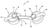
- FIG. 1is a side view of one example of a device for preparing an implanted medical apparatus for extraction
- FIG. 2is an exploded view of the device of FIG. 1 ;
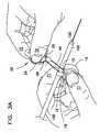
- FIG. 3illustrates a cardiac lead received along a surface of the device
- FIG. 3Aillustrates the hands of an operator positioning the cardiac lead along the device shown in FIG. 3 ;
- FIGS. 4 and 5illustrate successive stages of winding the device around the cardiac lead
- FIG. 6illustrates the release of the device handles from the lead
- FIG. 7illustrates the handles as released from the device, and the compression of the ends of the wire around the lead
- FIG. 8is a view of a proximal end portion of an implanted cardiac lead intended for extraction from a body vessel, and illustrating a cable protruding through the outer insulating portion of the lead;
- FIG. 9illustrates the lead and cable of FIG. 8 , and further illustrates a wire wound around the lead and cable;
- FIG. 10illustrates the lead, cable, and wire of FIG. 9 , and further illustrates an end of a lead extraction device arranged for passage over the proximal end of the lead segment of FIG. 9 ;
- FIG. 11illustrates the lead, cable, and wire as in FIG. 9 , wherein the wire is also wound around a locking stylet;
- FIG. 12is an exploded view of the device as shown in FIG. 2 , including a tether engaged with the wire;
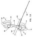
- FIG. 13illustrates a cardiac lead received along a surface of the device as shown in FIG. 3 , illustrating the tether engaged with the wire.
- distal and distaldenote a position, direction, or orientation that is generally toward, or in the direction of, the patient when the device is in use.
- proximaldenote a position, direction, or orientation that is generally away from the patient, or in the direction of the operator, during use of the device.
- FIG. 1illustrates a side view of one example of a device 10 for preparing an implanted medical apparatus for extraction.
- FIG. 2is an exploded view of the device of FIG. 1 .
- device 10includes a pair of handles 12 , 22 .
- Each handleincludes a handle body 14 , 24 having a surface, such as ledge 15 , 25 , configured for receiving a length of the implanted apparatus along the surface.
- a tab 16 , 26extends from handle body 14 , 24 , preferably at an opposite end of the handle body from ledge 15 , 25 .
- Tab 16 , 26includes an aperture 17 , 27 for receiving pin 18 , 28 .
- the pinmay be integral with the tab.
- Each main body 14 , 24includes a channel 20 , 30 inwardly directed from a slot 21 , 31 along ledge 15 , 25 .
- Channel 20 , 30extends rearwardly along main body 14 , 24 from slot 21 , 31 to a distance beyond handle body opening 13 , 23 .
- slot 21is visible in the orientation of FIG. 2
- slot 31 and the rearward extension of channels 20 , 30may be visualized by the phantom lines in FIG. 2 .
- Handles 12 , 22are joined by a generally flexible joinder member, such as wire 40 .
- wire 40has the general configuration of a rubber band, or a rectangle having rounded ends 42 , 44 .
- each one of ends 42 , 44is received through a respective one of slots 21 , 31 , and extends into a respective channel 20 , 30 .
- each pin 18 , 28is aligned with a respective tab aperture 17 , 27 , such that pin extension 19 , 29 extends through the aperture.
- Each tab 16 , 26is pivoted such that pin extension 19 , 29 is received in an appropriate one of openings 13 , 23 as described above, and thereby maintains the position of wire ends 42 , 44 in the respective channel 20 , 30 .
- the assembled deviceis shown in FIG. 1 .
- handlesmay be formed (e.g., by molding) from a variety of compositions, such as rigid plastics, and thermoplastic rubbers such as SANTOPRENE®.
- the tabs and pinsmay be formed from a more flexible composition, such as an acrylonitrile butadiene styrene (ABS) that is bondable to SANTOPRENE®.
- the wiremay be formed from various compositions, such as metals and metal alloys, having the strength and flexibility to enable the wire to be wound around the implanted structure targeted for extraction, and to maintain its wound configuration following removal of the handles.
- One particularly preferred exampleis a stainless steel composition that has been annealed to remove the spring tension from the wire.
- Wire 40will preferably be dimensioned such that respective ledges 15 , 25 are about 1 to 3 inches (2.54 to 7.62 cm) apart in the assembled device shown in FIG. 1 , and more preferably, about 2 inches (5.08 cm) apart.
- respective ledges 15 , 25are about 1 to 3 inches (2.54 to 7.62 cm) apart in the assembled device shown in FIG. 1 , and more preferably, about 2 inches (5.08 cm) apart.
- wire of greater, or of lesser, dimensionsmay be used in a particular case, but it is believed that a wire having the dimensions recited herein will suffice for most applications.
- a proximal end 102 of the implanted lead 100is severed from the pacemaker, defibrillator, etc., in a manner such that it is accessible to the operator.
- a locking stylet 120may be inserted into the lumen of the lead. Locking stylets are well known devices for use during the extraction of cardiac leads of the type having a lumen therethrough, and are further described, e.g., in the incorporated-by-reference U.S. Pat. Nos. 4,943,289 and 5,207,683.
- device 10is arranged such that the cardiac lead intended for removal is positioned along the ledge of one of the handles.
- lead 100is positioned along ledge 15 of handle 12 .
- the operatormay hold lead 100 against the ledge with a forefinger F 1 and maintain control of the handle with the thumb T 1 of the same hand. The operator then grasps handle 22 between the forefinger F 2 and thumb T 2 of the other hand.
- wire 40is wound around lead L in the proximal direction by winding handle 22 around the lead, as shown in FIG. 4 . While winding wire 40 around lead 100 , each of tabs 16 , 26 will typically be pointing in the general direction of the lead. The operator continues to wind handle 22 around lead 100 until wire 40 is completely wrapped around the lead, as shown in FIG. 5 . At this time, both handles 12 , 22 can be further wound in opposing directions around lead 100 , as indicated by the arrows in FIG. 5 , to tightly compress wire 40 around the lead.
- the proximal end of lead 100has now been prepared for extraction, e.g., by passage thereover of a conventional lead extraction device, such as the device disclosed in the incorporated-by-reference U.S. Pat. Publ. No. 2006/0235431.
- elongated implanted medical apparatusessuch as a cardiac (e.g. pacemaker or defibrillator) lead
- cardiace.g. pacemaker or defibrillator
- cableswires, coils, and the like (“cables”) that extend along the length of the implanted lead, or a portion of that length.
- conventional lead removal devicesare typically introduced over a proximal end of the lead that has previously been cut from the cardiac device.
- one or more of the cablesmay have worked their way through the insulation or other outer surface of the implanted lead.
- a cablecan work its way through the outer surface of a cardiac lead, such as the body environment in which the lead is positioned, the length of time in which the lead has been implanted, the degree of curvature of the vessel in which the lead has resided, etc.
- FIGS. 8-10illustrate another example of the management of a severed proximal end 202 of a lead 200 utilizing device 10 .
- a cable 210has worked its way through a length of the outer surface of the lead.
- lead 200is otherwise similar to lead 100 in the example of FIGS. 3-7 .
- FIG. 8illustrates a single cable 210 protruding from a discrete portion of lead 200 , those skilled in the art will appreciate that a lead intended for extraction may have more than one cable protruding therefrom, which cable(s) may protrude from different lengths of the lead.
- FIG. 9illustrates lead 200 after wire 40 has been wrapped around cable 210 , e.g., in the manner described above with reference to FIGS. 3-7 .
- wire 40brings cable 210 into close contact with the exterior surface of the lead.
- FIG. 10illustrates the lead and wire of FIG. 9 , and also illustrates a lead extraction device 300 positioned for advancement over lead 200 .
- lead extraction devicesare well-known in the art, and the skilled artisan can readily select a suitable extraction device for use in a particular extraction operation wherein wire 40 is wrapped around the lead.
- the extraction devicereadily advances over the entire lead structure, and is not hindered in such advancement by the present of a laterally-extending cable or like element.
- FIG. 11illustrates a variation of the example of FIGS. 8-10 .
- wire 40is also wrapped around locking stylet 120 .
- the locking styletmay not fully lock with the lead when introduced into the lumen, thereby causing the stylet to slip or otherwise disengage when pulled.
- wrapping the wire of device 10 around the lead and the stylet as shown in the figurean unintended withdrawal or disengagement of the locking stylet from the lead is prevented. Additionally, this arrangement establishes an additional locking point on the lead, thereby allowing for better overall control of the lead.
- FIGS. 12 and 13Another variation of device 10 is illustrated in FIGS. 12 and 13 .
- a tether 80is engaged with wire 40 .
- FIG. 12is an exploded view of device 10 , as in FIG. 2 , wherein tether 80 extends from wire 40 .
- FIG. 13illustrates a cardiac lead received along a surface of the device, in the same general manner as FIG. 3 .
- a tethermay be useful, e.g., in cases wherein a lumenless lead is being extracted, and/or in cases in which the lead has a lumen extending therethrough and yet it may not be practical to utilize a locking stylet.
- Tether 80can be formed of the same composition as wire 40 .
- the tetherwill generally have a length to enable it to extend through and beyond the extraction device.
- handle bodies 14 , 24need not necessarily have generally flat ledges 15 , 25 as shown. Rather, the handle bodies may have a gentle curvature, and in some instances may even have a groove, channel, or like structure, as long as the implanted apparatus, such as lead 100 , may be controllably received along a surface of the handle.
- the implanted apparatussuch as lead 100
- the respective handlesmay have different configurations. In some instances, only one handle (such as handle 12 in the figures) need have a ledge or other surface for receiving the implanted apparatus therealong.
- handles 12 , 22need not be rounded as shown, as other geometrically shaped handles will also function in the manner as the handles shown.
- tabs 16 , 26need not necessarily be integral with the handle bodies, as non-integral tabs and like structures will normally be capable of being positioned in like manner to carry out the functions of the tabs as described.
- device 10may also find other uses in the medical field. For example, if it is desirous to remove a tenaciously-calcified implanted structure, such as an infusion catheter, from a vessel, a locking stylet-like device or a balloon-tipped removal device may be arranged to engage the distal portion of the structure in well-known manner. In this case, device 10 can be arranged to couple the proximal end of the structure to the removal device. As a result, the physician can extract the implanted structure by pulling on only one device.
- a locking stylet-like device or a balloon-tipped removal devicemay be arranged to engage the distal portion of the structure in well-known manner.
- device 10can be arranged to couple the proximal end of the structure to the removal device. As a result, the physician can extract the implanted structure by pulling on only one device.
Landscapes
- Health & Medical Sciences (AREA)
- Life Sciences & Earth Sciences (AREA)
- Engineering & Computer Science (AREA)
- Biomedical Technology (AREA)
- Nuclear Medicine, Radiotherapy & Molecular Imaging (AREA)
- Animal Behavior & Ethology (AREA)
- General Health & Medical Sciences (AREA)
- Public Health (AREA)
- Veterinary Medicine (AREA)
- Heart & Thoracic Surgery (AREA)
- Surgery (AREA)
- Radiology & Medical Imaging (AREA)
- Medical Informatics (AREA)
- Molecular Biology (AREA)
- Cardiology (AREA)
- Vascular Medicine (AREA)
- Electrotherapy Devices (AREA)
- Surgical Instruments (AREA)
Abstract
Description
Claims (5)
Priority Applications (6)
| Application Number | Priority Date | Filing Date | Title |
|---|---|---|---|
| US13/716,975US9055930B2 (en) | 2012-12-17 | 2012-12-17 | Device for preparing an implanted medical apparatus for extraction |
| CA2833408ACA2833408C (en) | 2012-12-17 | 2013-11-14 | Device for preparing an implanted medical apparatus for extraction |
| EP13196293.8AEP2742871B1 (en) | 2012-12-17 | 2013-12-09 | Device for preparing an implanted medical apparatus for extraction |
| AU2013270642AAU2013270642B2 (en) | 2012-12-17 | 2013-12-16 | Device for preparing an implanted medical apparatus for extraction |
| JP2013259223AJP5799076B2 (en) | 2012-12-17 | 2013-12-16 | A device to prepare the implanted medical device for removal |
| US14/711,240US9155878B2 (en) | 2012-12-17 | 2015-05-13 | Device for preparing an implanted medical apparatus for extraction |
Applications Claiming Priority (1)
| Application Number | Priority Date | Filing Date | Title |
|---|---|---|---|
| US13/716,975US9055930B2 (en) | 2012-12-17 | 2012-12-17 | Device for preparing an implanted medical apparatus for extraction |
Related Child Applications (1)
| Application Number | Title | Priority Date | Filing Date |
|---|---|---|---|
| US14/711,240DivisionUS9155878B2 (en) | 2012-12-17 | 2015-05-13 | Device for preparing an implanted medical apparatus for extraction |
Publications (2)
| Publication Number | Publication Date |
|---|---|
| US20140171960A1 US20140171960A1 (en) | 2014-06-19 |
| US9055930B2true US9055930B2 (en) | 2015-06-16 |
Family
ID=49841492
Family Applications (2)
| Application Number | Title | Priority Date | Filing Date |
|---|---|---|---|
| US13/716,975Active2033-01-26US9055930B2 (en) | 2012-12-17 | 2012-12-17 | Device for preparing an implanted medical apparatus for extraction |
| US14/711,240ActiveUS9155878B2 (en) | 2012-12-17 | 2015-05-13 | Device for preparing an implanted medical apparatus for extraction |
Family Applications After (1)
| Application Number | Title | Priority Date | Filing Date |
|---|---|---|---|
| US14/711,240ActiveUS9155878B2 (en) | 2012-12-17 | 2015-05-13 | Device for preparing an implanted medical apparatus for extraction |
Country Status (5)
| Country | Link |
|---|---|
| US (2) | US9055930B2 (en) |
| EP (1) | EP2742871B1 (en) |
| JP (1) | JP5799076B2 (en) |
| AU (1) | AU2013270642B2 (en) |
| CA (1) | CA2833408C (en) |
Cited By (2)
| Publication number | Priority date | Publication date | Assignee | Title |
|---|---|---|---|---|
| US10933247B2 (en) | 2017-08-21 | 2021-03-02 | MRM MedTech, LLC | Lead with integrated features to facilitate extraction and associated methods of extraction |
| US11865334B2 (en) | 2017-08-21 | 2024-01-09 | MRM MedTech, LLC | Lead with integrated feature including a low friction component to facilitate extraction and associated methods of extraction |
Families Citing this family (10)
| Publication number | Priority date | Publication date | Assignee | Title |
|---|---|---|---|---|
| US9220523B2 (en) | 2009-09-14 | 2015-12-29 | The Spectranetics Corporation | Snaring systems and methods |
| JP3194755U (en)* | 2014-09-02 | 2014-12-11 | 嗣允 藤原 | Pacemaker lead sheath for peeling adhesion |
| US10105533B2 (en) | 2014-12-30 | 2018-10-23 | The Spectranetics Corporation | Multi-loop coupling for lead extension and extraction |
| US9884184B2 (en)* | 2014-12-30 | 2018-02-06 | The Spectranetics Corporation | Wire hook coupling for lead extension and extraction |
| US10576274B2 (en) | 2014-12-30 | 2020-03-03 | Spectranetics Llc | Expanding coil coupling for lead extension and extraction |
| US9731113B2 (en)* | 2014-12-30 | 2017-08-15 | The Spectranetics Corporation | Collapsing coil coupling for lead extension and extraction |
| US10960216B2 (en)* | 2016-03-31 | 2021-03-30 | Cardiac Pacemakers, Inc. | Extraction devices configued to extract chronically implanted medical devices |
| US10952785B2 (en) | 2016-08-01 | 2021-03-23 | Medtronic Advanced Energy, Llc | Device for medical lead extraction |
| WO2018090044A1 (en) | 2016-11-14 | 2018-05-17 | Medtronic Advanced Energy Llc | Colored vitreous enamel composition for electrosurgical tool |
| EP3456379B1 (en)* | 2017-09-15 | 2020-03-11 | Sorin CRM SAS | Explantation assembly for retrieving intracorporeal autonomous capsules |
Citations (47)
| Publication number | Priority date | Publication date | Assignee | Title |
|---|---|---|---|---|
| US2147160A (en)* | 1937-10-09 | 1939-02-14 | Emil T Hagist | Wire clamp and connecter |
| JPH02180248A (en) | 1988-11-09 | 1990-07-13 | Medical Eng & Dev Inst Inc | Apparatus and method for removing linear corpus |
| US4943289A (en) | 1989-05-03 | 1990-07-24 | Cook Pacemaker Corporation | Apparatus for removing an elongated structure implanted in biological tissue |
| US4988347A (en) | 1988-11-09 | 1991-01-29 | Cook Pacemaker Corporation | Method and apparatus for separating a coiled structure from biological tissue |
| US5011482A (en) | 1989-01-17 | 1991-04-30 | Cook Pacemaker Corporation | Apparatus for removing an elongated structure implanted in biological tissue |
| US5013310A (en) | 1988-11-09 | 1991-05-07 | Cook Pacemaker Corporation | Method and apparatus for removing an implanted pacemaker lead |
| US5207683A (en) | 1988-11-09 | 1993-05-04 | Cook Pacemaker Corporation | Apparatus for removing an elongated structure implanted in biological tissue |
| US5217438A (en)* | 1992-07-20 | 1993-06-08 | Dlp, Inc. | Needle stop and safety sheath |
| JPH06508274A (en) | 1991-06-07 | 1994-09-22 | ピー. マークス,マイケル | Catheter device with retractable wire and method thereof |
| US5423806A (en) | 1993-10-01 | 1995-06-13 | Medtronic, Inc. | Laser extractor for an implanted object |
| US5507751A (en) | 1988-11-09 | 1996-04-16 | Cook Pacemaker Corporation | Locally flexible dilator sheath |
| JPH08132778A (en) | 1994-11-11 | 1996-05-28 | Hino Seisakusho:Kk | Sheet binder made of synthetic resin |
| US5697936A (en) | 1988-11-10 | 1997-12-16 | Cook Pacemaker Corporation | Device for removing an elongated structure implanted in biological tissue |
| US5993463A (en)* | 1997-05-15 | 1999-11-30 | Regents Of The University Of Minnesota | Remote actuation of trajectory guide |
| US6045572A (en)* | 1998-10-16 | 2000-04-04 | Cardiac Assist Technologies, Inc. | System, method and apparatus for sternal closure |
| US6136005A (en) | 1988-11-09 | 2000-10-24 | Cook Pacemaker Corporation | Apparatus for removing a coiled structure implanted in biological tissue, having expandable means including a laterally deflectable member |
| US6156055A (en) | 1999-03-23 | 2000-12-05 | Nitinol Medical Technologies Inc. | Gripping device for implanting, repositioning or extracting an object within a body vessel |
| US6419674B1 (en) | 1996-11-27 | 2002-07-16 | Cook Vascular Incorporated | Radio frequency dilator sheath |
| US6687548B2 (en) | 2000-05-17 | 2004-02-03 | Cook Vascular Incorporated | Apparatus for removing an elongated structure implanted in biological tissue |
| US20040030335A1 (en)* | 2002-05-14 | 2004-02-12 | University Of Pittsburgh | Device and method of use for functional isolation of animal or human tissues |
| US20040147958A1 (en)* | 2002-12-11 | 2004-07-29 | Usgi Medical | Apparatus and methods for forming and securing gastrointestinal tissue folds |
| US20050049592A1 (en)* | 2000-04-04 | 2005-03-03 | Keith Peter T. | Devices and methods for annular repair of intervertebral discs |
| US20050192591A1 (en) | 2004-02-27 | 2005-09-01 | Lui Chun K. | Device for removing an elongated structure implanted in biological tissue |
| US20050288758A1 (en) | 2003-08-08 | 2005-12-29 | Jones Timothy S | Methods and apparatuses for implanting and removing an electrical stimulation lead |
| US7076305B2 (en)* | 2001-05-01 | 2006-07-11 | Intrapace, Inc. | Gastric device and instrument system and method |
| US20060235431A1 (en) | 2005-04-15 | 2006-10-19 | Cook Vascular Incorporated | Lead extraction device |
| US20080103504A1 (en)* | 2006-10-30 | 2008-05-01 | Schmitz Gregory P | Percutaneous spinal stenosis treatment |
| US20080147084A1 (en)* | 2006-12-07 | 2008-06-19 | Baxano, Inc. | Tissue removal devices and methods |
| US20090198282A1 (en)* | 2004-03-09 | 2009-08-06 | Louis Fielding | Spinal implant and method for restricting spinal flexion |
| US20090222021A1 (en)* | 2008-02-29 | 2009-09-03 | Raymond Jeh-Yuan Chang | Apparatus and Associated Method for Facilitating Implantation of Leads of a Cardiac Pacemaker |
| US20090259260A1 (en)* | 1999-10-20 | 2009-10-15 | Anulex Technologies, Inc. | Method and apparatus for the treatment of the intervertebral disc annulus |
| US20090281579A1 (en)* | 2008-05-08 | 2009-11-12 | Aesculap Implant Systems, Inc. | Minimally invasive spinal stabilization system |
| US7651504B2 (en) | 2003-02-05 | 2010-01-26 | Cook Vascular Incorporated | Device for removing an elongated structure implanted in biological tissue |
| US20100087857A1 (en)* | 2004-11-05 | 2010-04-08 | Stone Kevin T | Soft Tissue Repair Device and Method |
| US20100222787A1 (en) | 2009-03-02 | 2010-09-02 | Cook Vascular Incorporated | Tension control device |
| US20100234862A1 (en)* | 2007-12-06 | 2010-09-16 | Manoj Patel | Surgical clamp and method of clamping an organ |
| US20100292732A1 (en)* | 2009-05-12 | 2010-11-18 | Foundry Newco Xi, Inc. | Suture anchors with one-way cinching mechanisms |
| US20100331883A1 (en)* | 2004-10-15 | 2010-12-30 | Schmitz Gregory P | Access and tissue modification systems and methods |
| US7905904B2 (en)* | 2006-02-03 | 2011-03-15 | Biomet Sports Medicine, Llc | Soft tissue repair device and associated methods |
| US20110109072A1 (en)* | 2009-11-12 | 2011-05-12 | Lisa Ligouri | Flexible ski tip connecting device |
| US20110213417A1 (en)* | 2007-09-12 | 2011-09-01 | Foerster Seth A | Implant and delivery system for soft tissue repair |
| US20110230893A1 (en)* | 2010-03-19 | 2011-09-22 | Boston Scientific Neuromodulation Corporation | Systems and methods for making and using electrical stimulation systems having multi-lead-element lead bodies |
| US20110238078A1 (en) | 2010-03-29 | 2011-09-29 | Cook Medical Technologies Llc | Device and method for positioning an implanted structure to facilitate removal |
| US20110237967A1 (en)* | 2008-03-25 | 2011-09-29 | Ebr Systems, Inc. | Temporary electrode connection for wireless pacing systems |
| US20120029335A1 (en) | 2010-07-29 | 2012-02-02 | Cameron Health, Inc. | Subcutaneous Leads and Methods of Implant and Explant |
| US8192430B2 (en) | 2006-12-15 | 2012-06-05 | Cook Medical Technologies Llc | Device for extracting an elongated structure implanted in biological tissue |
| US8632590B2 (en)* | 1999-10-20 | 2014-01-21 | Anulex Technologies, Inc. | Apparatus and methods for the treatment of the intervertebral disc |
Family Cites Families (4)
| Publication number | Priority date | Publication date | Assignee | Title |
|---|---|---|---|---|
| US5171233A (en)* | 1990-04-25 | 1992-12-15 | Microvena Corporation | Snare-type probe |
| US5678579A (en)* | 1994-02-24 | 1997-10-21 | Televideo Consultants, Inc. | Apparatus and method for positioning and moving a flexible element |
| US6183802B1 (en) | 1999-05-27 | 2001-02-06 | General Mills, Inc. | Dairy products and method of preparation |
| US6517550B1 (en)* | 2000-02-02 | 2003-02-11 | Board Of Regents, The University Of Texas System | Foreign body retrieval device |
- 2012
- 2012-12-17USUS13/716,975patent/US9055930B2/enactiveActive
- 2013
- 2013-11-14CACA2833408Apatent/CA2833408C/enactiveActive
- 2013-12-09EPEP13196293.8Apatent/EP2742871B1/enactiveActive
- 2013-12-16AUAU2013270642Apatent/AU2013270642B2/enactiveActive
- 2013-12-16JPJP2013259223Apatent/JP5799076B2/enactiveActive
- 2015
- 2015-05-13USUS14/711,240patent/US9155878B2/enactiveActive
Patent Citations (55)
| Publication number | Priority date | Publication date | Assignee | Title |
|---|---|---|---|---|
| US2147160A (en)* | 1937-10-09 | 1939-02-14 | Emil T Hagist | Wire clamp and connecter |
| US5507751A (en) | 1988-11-09 | 1996-04-16 | Cook Pacemaker Corporation | Locally flexible dilator sheath |
| JPH02180248A (en) | 1988-11-09 | 1990-07-13 | Medical Eng & Dev Inst Inc | Apparatus and method for removing linear corpus |
| US4988347A (en) | 1988-11-09 | 1991-01-29 | Cook Pacemaker Corporation | Method and apparatus for separating a coiled structure from biological tissue |
| US6136005A (en) | 1988-11-09 | 2000-10-24 | Cook Pacemaker Corporation | Apparatus for removing a coiled structure implanted in biological tissue, having expandable means including a laterally deflectable member |
| US5013310A (en) | 1988-11-09 | 1991-05-07 | Cook Pacemaker Corporation | Method and apparatus for removing an implanted pacemaker lead |
| US5207683A (en) | 1988-11-09 | 1993-05-04 | Cook Pacemaker Corporation | Apparatus for removing an elongated structure implanted in biological tissue |
| US5632749A (en) | 1988-11-09 | 1997-05-27 | Cook Pacemaker Corporation | Apparatus for removing an elongated structure implanted in biological tissue |
| US5697936A (en) | 1988-11-10 | 1997-12-16 | Cook Pacemaker Corporation | Device for removing an elongated structure implanted in biological tissue |
| US5011482A (en) | 1989-01-17 | 1991-04-30 | Cook Pacemaker Corporation | Apparatus for removing an elongated structure implanted in biological tissue |
| US4943289A (en) | 1989-05-03 | 1990-07-24 | Cook Pacemaker Corporation | Apparatus for removing an elongated structure implanted in biological tissue |
| JPH06508274A (en) | 1991-06-07 | 1994-09-22 | ピー. マークス,マイケル | Catheter device with retractable wire and method thereof |
| US5217438A (en)* | 1992-07-20 | 1993-06-08 | Dlp, Inc. | Needle stop and safety sheath |
| US5423806A (en) | 1993-10-01 | 1995-06-13 | Medtronic, Inc. | Laser extractor for an implanted object |
| JPH08132778A (en) | 1994-11-11 | 1996-05-28 | Hino Seisakusho:Kk | Sheet binder made of synthetic resin |
| US6419674B1 (en) | 1996-11-27 | 2002-07-16 | Cook Vascular Incorporated | Radio frequency dilator sheath |
| US5993463A (en)* | 1997-05-15 | 1999-11-30 | Regents Of The University Of Minnesota | Remote actuation of trajectory guide |
| US6045572A (en)* | 1998-10-16 | 2000-04-04 | Cardiac Assist Technologies, Inc. | System, method and apparatus for sternal closure |
| US6156055A (en) | 1999-03-23 | 2000-12-05 | Nitinol Medical Technologies Inc. | Gripping device for implanting, repositioning or extracting an object within a body vessel |
| US20090259260A1 (en)* | 1999-10-20 | 2009-10-15 | Anulex Technologies, Inc. | Method and apparatus for the treatment of the intervertebral disc annulus |
| US8632590B2 (en)* | 1999-10-20 | 2014-01-21 | Anulex Technologies, Inc. | Apparatus and methods for the treatment of the intervertebral disc |
| US20110202137A1 (en)* | 2000-04-04 | 2011-08-18 | Anulex Technologies, Inc. | Devices and methods for annular repair of intervertebral discs |
| US20070239280A1 (en)* | 2000-04-04 | 2007-10-11 | Anulex Technologies, Inc. | Devices and methods for annular repair of intervertebral discs |
| US20050049592A1 (en)* | 2000-04-04 | 2005-03-03 | Keith Peter T. | Devices and methods for annular repair of intervertebral discs |
| US6687548B2 (en) | 2000-05-17 | 2004-02-03 | Cook Vascular Incorporated | Apparatus for removing an elongated structure implanted in biological tissue |
| US6712826B2 (en) | 2000-05-17 | 2004-03-30 | Cook Vascular Incorporated | Apparatus for removing an elongated structure implanted in biological tissue |
| US7359756B2 (en) | 2000-05-17 | 2008-04-15 | Cook Vascular Incorporated | Method of removing an elongated structure implanted in biological tissue |
| US7076305B2 (en)* | 2001-05-01 | 2006-07-11 | Intrapace, Inc. | Gastric device and instrument system and method |
| US20040030335A1 (en)* | 2002-05-14 | 2004-02-12 | University Of Pittsburgh | Device and method of use for functional isolation of animal or human tissues |
| US20040147958A1 (en)* | 2002-12-11 | 2004-07-29 | Usgi Medical | Apparatus and methods for forming and securing gastrointestinal tissue folds |
| US7651504B2 (en) | 2003-02-05 | 2010-01-26 | Cook Vascular Incorporated | Device for removing an elongated structure implanted in biological tissue |
| US20050288758A1 (en) | 2003-08-08 | 2005-12-29 | Jones Timothy S | Methods and apparatuses for implanting and removing an electrical stimulation lead |
| US20050192591A1 (en) | 2004-02-27 | 2005-09-01 | Lui Chun K. | Device for removing an elongated structure implanted in biological tissue |
| US20090198282A1 (en)* | 2004-03-09 | 2009-08-06 | Louis Fielding | Spinal implant and method for restricting spinal flexion |
| US20100331883A1 (en)* | 2004-10-15 | 2010-12-30 | Schmitz Gregory P | Access and tissue modification systems and methods |
| US20100087857A1 (en)* | 2004-11-05 | 2010-04-08 | Stone Kevin T | Soft Tissue Repair Device and Method |
| WO2006113438A3 (en) | 2005-04-15 | 2007-04-26 | Cook Vascular Inc | Lead extraction device |
| WO2006113438A2 (en) | 2005-04-15 | 2006-10-26 | Cook Vascular Incorporated | Lead extraction device |
| EP1903957B1 (en) | 2005-04-15 | 2011-12-28 | Cook Medical Technologies LLC | Lead extraction device |
| US20060235431A1 (en) | 2005-04-15 | 2006-10-19 | Cook Vascular Incorporated | Lead extraction device |
| US7905904B2 (en)* | 2006-02-03 | 2011-03-15 | Biomet Sports Medicine, Llc | Soft tissue repair device and associated methods |
| US20080103504A1 (en)* | 2006-10-30 | 2008-05-01 | Schmitz Gregory P | Percutaneous spinal stenosis treatment |
| US20080147084A1 (en)* | 2006-12-07 | 2008-06-19 | Baxano, Inc. | Tissue removal devices and methods |
| US8192430B2 (en) | 2006-12-15 | 2012-06-05 | Cook Medical Technologies Llc | Device for extracting an elongated structure implanted in biological tissue |
| US20110213417A1 (en)* | 2007-09-12 | 2011-09-01 | Foerster Seth A | Implant and delivery system for soft tissue repair |
| US20100234862A1 (en)* | 2007-12-06 | 2010-09-16 | Manoj Patel | Surgical clamp and method of clamping an organ |
| US20090222021A1 (en)* | 2008-02-29 | 2009-09-03 | Raymond Jeh-Yuan Chang | Apparatus and Associated Method for Facilitating Implantation of Leads of a Cardiac Pacemaker |
| US20110237967A1 (en)* | 2008-03-25 | 2011-09-29 | Ebr Systems, Inc. | Temporary electrode connection for wireless pacing systems |
| US20090281579A1 (en)* | 2008-05-08 | 2009-11-12 | Aesculap Implant Systems, Inc. | Minimally invasive spinal stabilization system |
| US20100222787A1 (en) | 2009-03-02 | 2010-09-02 | Cook Vascular Incorporated | Tension control device |
| US20100292732A1 (en)* | 2009-05-12 | 2010-11-18 | Foundry Newco Xi, Inc. | Suture anchors with one-way cinching mechanisms |
| US20110109072A1 (en)* | 2009-11-12 | 2011-05-12 | Lisa Ligouri | Flexible ski tip connecting device |
| US20110230893A1 (en)* | 2010-03-19 | 2011-09-22 | Boston Scientific Neuromodulation Corporation | Systems and methods for making and using electrical stimulation systems having multi-lead-element lead bodies |
| US20110238078A1 (en) | 2010-03-29 | 2011-09-29 | Cook Medical Technologies Llc | Device and method for positioning an implanted structure to facilitate removal |
| US20120029335A1 (en) | 2010-07-29 | 2012-02-02 | Cameron Health, Inc. | Subcutaneous Leads and Methods of Implant and Explant |
Non-Patent Citations (2)
| Title |
|---|
| English language translation of Office Action for corresponding Japanese Application No. 2013-259223, which includes Record of Search for Prior Art Documents, dated Oct. 21, 2014, 3p. |
| Search Report for Corresponding EP Application No. EP 13 19 6293; dated Apr. 2, 2014; 10p. |
Cited By (2)
| Publication number | Priority date | Publication date | Assignee | Title |
|---|---|---|---|---|
| US10933247B2 (en) | 2017-08-21 | 2021-03-02 | MRM MedTech, LLC | Lead with integrated features to facilitate extraction and associated methods of extraction |
| US11865334B2 (en) | 2017-08-21 | 2024-01-09 | MRM MedTech, LLC | Lead with integrated feature including a low friction component to facilitate extraction and associated methods of extraction |
Also Published As
| Publication number | Publication date |
|---|---|
| JP5799076B2 (en) | 2015-10-21 |
| US20150238751A1 (en) | 2015-08-27 |
| CA2833408C (en) | 2015-11-10 |
| AU2013270642A1 (en) | 2014-07-03 |
| EP2742871A1 (en) | 2014-06-18 |
| EP2742871B1 (en) | 2016-05-18 |
| US9155878B2 (en) | 2015-10-13 |
| US20140171960A1 (en) | 2014-06-19 |
| AU2013270642B2 (en) | 2014-12-11 |
| CA2833408A1 (en) | 2014-06-17 |
| JP2014117619A (en) | 2014-06-30 |
Similar Documents
| Publication | Publication Date | Title |
|---|---|---|
| US9155878B2 (en) | Device for preparing an implanted medical apparatus for extraction | |
| EP1984072B1 (en) | Device for removing lumenless leads | |
| US5697936A (en) | Device for removing an elongated structure implanted in biological tissue | |
| US20240033485A1 (en) | Anchor instrumentation and methods | |
| US5013310A (en) | Method and apparatus for removing an implanted pacemaker lead | |
| US8613729B2 (en) | Anchor and anchor deployment apparatus | |
| US8192430B2 (en) | Device for extracting an elongated structure implanted in biological tissue | |
| US5651781A (en) | Surgical cutting instrument | |
| US20100222787A1 (en) | Tension control device | |
| US11890483B2 (en) | Apparatus and method for implanting an implantable device | |
| CN104415452B (en) | Enhancing outer sheath for draw-out device | |
| WO1985004320A1 (en) | Endocardial lead extraction apparatus and method | |
| WO2018005549A1 (en) | Delivery systems for implantable medical devices, and associated tethering assemblies and methods | |
| WO2011057210A2 (en) | Methods and systems for removal of implantable intravascular devices | |
| WO2015187478A1 (en) | Implant tool for substernal or pericardial access | |
| US10967174B2 (en) | Cardiac lead wire protector | |
| CN119486782A (en) | Biostimulator delivery system with flexible tether |
Legal Events
| Date | Code | Title | Description |
|---|---|---|---|
| AS | Assignment | Owner name:COOK MEDICAL TECHNOLOGIES LLC, INDIANA Free format text:ASSIGNMENT OF ASSIGNORS INTEREST;ASSIGNOR:COOK VASCULAR INCORPORATED;REEL/FRAME:029503/0016 Effective date:20121210 Owner name:COOK VASCULAR INCORPORATED, PENNSYLVANIA Free format text:ASSIGNMENT OF ASSIGNORS INTEREST;ASSIGNORS:GOODE, LOUIS B.;LUI, CHUN KEE;EMMERT, MICHAEL WAYNE;AND OTHERS;REEL/FRAME:029502/0991 Effective date:20121210 | |
| STCF | Information on status: patent grant | Free format text:PATENTED CASE | |
| MAFP | Maintenance fee payment | Free format text:PAYMENT OF MAINTENANCE FEE, 4TH YEAR, LARGE ENTITY (ORIGINAL EVENT CODE: M1551); ENTITY STATUS OF PATENT OWNER: LARGE ENTITY Year of fee payment:4 | |
| MAFP | Maintenance fee payment | Free format text:PAYMENT OF MAINTENANCE FEE, 8TH YEAR, LARGE ENTITY (ORIGINAL EVENT CODE: M1552); ENTITY STATUS OF PATENT OWNER: LARGE ENTITY Year of fee payment:8 | |
| AS | Assignment | Owner name:WILMINGTON TRUST, NATIONAL ASSOCIATION, AS COLLATERAL AGENT, DELAWARE Free format text:SECURITY INTEREST;ASSIGNOR:COOK MEDICAL TECHNOLOGIES LLC;REEL/FRAME:066700/0277 Effective date:20240227 | |
| AS | Assignment | Owner name:MERIT MEDICAL SYSTEMS, INC., UTAH Free format text:ASSIGNMENT OF ASSIGNORS INTEREST;ASSIGNOR:COOK MEDICAL TECHNOLOGIES LLC;REEL/FRAME:069188/0282 Effective date:20241101 | |
| AS | Assignment | Owner name:COOK MEDICAL TECHNOLOGIES LLC, INDIANA Free format text:RELEASE BY SECURED PARTY;ASSIGNOR:WILMINGTON TRUST, NATIONAL ASSOCIATION, AS COLLATERAL AGENT;REEL/FRAME:070140/0329 Effective date:20241101 |