US9054765B2 - Systems and methods for suppressing interference in a wireless communication system - Google Patents
Systems and methods for suppressing interference in a wireless communication systemDownload PDFInfo
- Publication number
- US9054765B2 US9054765B2US13/655,766US201213655766AUS9054765B2US 9054765 B2US9054765 B2US 9054765B2US 201213655766 AUS201213655766 AUS 201213655766AUS 9054765 B2US9054765 B2US 9054765B2
- Authority
- US
- United States
- Prior art keywords
- channel
- interference
- receiving device
- characteristic
- spatial correlation
- Prior art date
- Legal status (The legal status is an assumption and is not a legal conclusion. Google has not performed a legal analysis and makes no representation as to the accuracy of the status listed.)
- Active
Links
- 238000000034methodMethods0.000titleclaimsabstractdescription26
- 238000004891communicationMethods0.000titledescription10
- 239000011159matrix materialSubstances0.000claimsdescription73
- 238000001914filtrationMethods0.000claimsdescription15
- 239000000969carrierSubstances0.000claimsdescription4
- 230000005540biological transmissionEffects0.000abstractdescription27
- 238000010586diagramMethods0.000description12
- 230000007423decreaseEffects0.000description5
- 238000005516engineering processMethods0.000description4
- 230000002452interceptive effectEffects0.000description4
- 230000008901benefitEffects0.000description2
- 230000003247decreasing effectEffects0.000description2
- 230000004048modificationEffects0.000description2
- 238000012986modificationMethods0.000description2
- 230000008569processEffects0.000description2
- 230000008859changeEffects0.000description1
- 230000002596correlated effectEffects0.000description1
- 230000000875corresponding effectEffects0.000description1
- 238000011143downstream manufacturingMethods0.000description1
- 230000007774longtermEffects0.000description1
- 230000008685targetingEffects0.000description1
- 230000002087whitening effectEffects0.000description1
Images


Classifications
- H—ELECTRICITY
- H04—ELECTRIC COMMUNICATION TECHNIQUE
- H04B—TRANSMISSION
- H04B7/00—Radio transmission systems, i.e. using radiation field
- H04B7/02—Diversity systems; Multi-antenna system, i.e. transmission or reception using multiple antennas
- H04B7/04—Diversity systems; Multi-antenna system, i.e. transmission or reception using multiple antennas using two or more spaced independent antennas
- H04B7/08—Diversity systems; Multi-antenna system, i.e. transmission or reception using multiple antennas using two or more spaced independent antennas at the receiving station
- H04B7/0837—Diversity systems; Multi-antenna system, i.e. transmission or reception using multiple antennas using two or more spaced independent antennas at the receiving station using pre-detection combining
- H04B7/0842—Weighted combining
- H04B7/0848—Joint weighting
- H04B7/0854—Joint weighting using error minimizing algorithms, e.g. minimum mean squared error [MMSE], "cross-correlation" or matrix inversion
- H—ELECTRICITY
- H04—ELECTRIC COMMUNICATION TECHNIQUE
- H04B—TRANSMISSION
- H04B7/00—Radio transmission systems, i.e. using radiation field
- H04B7/02—Diversity systems; Multi-antenna system, i.e. transmission or reception using multiple antennas
- H04B7/04—Diversity systems; Multi-antenna system, i.e. transmission or reception using multiple antennas using two or more spaced independent antennas
- H04B7/08—Diversity systems; Multi-antenna system, i.e. transmission or reception using multiple antennas using two or more spaced independent antennas at the receiving station
- H04B7/0837—Diversity systems; Multi-antenna system, i.e. transmission or reception using multiple antennas using two or more spaced independent antennas at the receiving station using pre-detection combining
- H04B7/0842—Weighted combining
- H04B7/0848—Joint weighting
- H04B7/0851—Joint weighting using training sequences or error signal
- H—ELECTRICITY
- H04—ELECTRIC COMMUNICATION TECHNIQUE
- H04B—TRANSMISSION
- H04B1/00—Details of transmission systems, not covered by a single one of groups H04B3/00 - H04B13/00; Details of transmission systems not characterised by the medium used for transmission
- H04B1/69—Spread spectrum techniques
- H04B1/707—Spread spectrum techniques using direct sequence modulation
- H04B2001/70724—Spread spectrum techniques using direct sequence modulation featuring pilot assisted reception
Definitions
- the technology described in this patent documentrelates generally to wireless communications and more particularly to systems and methods for suppressing interference in a signal received at a device including two or more receive antennas.
- SIMOSingle Input Multiple Output
- MIMOMultiple Input Multiple Output
- Both technologiesutilize multiple receive antennas on a receiver to enable a multipath rich environment with multiple orthogonal channels existing between a transmitter and the receiver. Data signals can be transmitted in parallel over these channels, enabling increased data throughput and link range.
- SIMO and MIMO technologieshave been used in wireless communication standards such as IEEE 802.11 (WiFi), 4G, 3GPP Long Term Evolution (LTE), WiMAX, and HSPA+.
- interference in a data signal received by a receiving devicemay have a significant impact on throughput and reliability of data transmissions in these systems.
- the present disclosureis directed to systems and methods for suppressing interference from a received data signal.
- a characteristic of a channelis estimated, the channel being configured for transmission of data between a transmitting device and a receiving device having two or more receive antennas.
- a spatial correlation of interferenceis determined for the two or more receive antennas based on the channel characteristic.
- the received data signalis filtered based on the spatial correlation.
- a system for suppressing interference from a received data signalincludes a channel estimation block configured to estimate a characteristic of a channel, the channel being configured for transmission of data between a transmitting device and a receiving device having two or more receive antennas.
- a spatial correlation blockis configured to determine a spatial correlation of interference at the two or more receive antennas based on the channel characteristic, and a filtering block is configured to use the spatial correlation of the interference to suppress interference from a signal received at the receiving device.
- FIG. 1is a block diagram of an example communications system utilizing an interference rejection filter to decrease interference in a data signal received by a receiver.
- FIG. 2is a block diagram depicting a SIMO (Single Input Multiple Output) system employing an interference rejection filter to decrease interference in a data signal received by a receiver.
- SIMOSingle Input Multiple Output
- FIG. 3is a block diagram illustrating a system that uses pilot sequence data to estimate characteristics of a transmission channel.
- FIG. 4is a block diagram illustrating a system that includes a second transmitter-receiver pair that provides a source of interference.
- FIG. 5is a block diagram depicting example processing by physical layer and media access control layer modules of a received data signal to suppress interference.
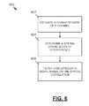
- FIG. 6is a flow diagram depicting a method for reducing interference from a received data signal.
- FIG. 7depicts a filter for reducing interference from a received data signal.
- FIG. 1is a block diagram of an example communications system 100 utilizing an interference ejection filter 102 to decrease interference in a data signal received at a receiver 104 .
- an input data stream 106is received by a transmitter 108 and subsequently transmitted over a plurality of transmission antennas 110 .
- the transmission antennas 110transmit the input data stream 106 using a plurality of signals x 1 , . . . , x n , where n is equal to a number of transmission antennas of the transmitter 108 .
- x nare transmitted via a channel 112 to a plurality of receive antennas 114 associated with the receiver 104 .
- the channel 112affects the plurality of signals x 1 , . . . , x n transmitted, such that modified versions of these signals, y 1 , . . . , y m , are received on the receive antennas 114 , where in is equal to the number of receive antennas of the receiver 104 .
- the received signals y 1 , . . . , y m on the receive antennas 114may be modified from the transmitted signals x 1 , . . .
- interferencecan be injected into the signal modified by channel 112 by an interferene source 115 , such as a wireless device transmitting to a wireless receiver other than receiver 104 (e.g., a WiFi STA communicating with a different base station (AP), a mobile phone communication with a different base station).
- an interferene source 115such as a wireless device transmitting to a wireless receiver other than receiver 104 (e.g., a WiFi STA communicating with a different base station (AP), a mobile phone communication with a different base station).
- yis a data matrix that defines the plurality of signals y 1 , . . . , y m received on the receive antennas 114
- zis an interference-and-noise matrix that affects the transmission of the signals x 1 , . . . , x n .
- a transmitteris simultaneously transmitting to multiple receivers.
- a particular receiverwill receive the signals targeting at that receiver together with signals that is not intended for it, all from the same transmitter. This will happen, for example, in the downlink multi-user MIMO transmission in 3GPP LTE and IEEE 802.11.
- the transmitted signal 110 from the transmitter 108can be a weighted sum of the signals intended for receiver 104 , together with the signals not intended for receiver 104 , which the interference comprises of.
- the data matrix x in Equation 1contains both desired signals and interference
- the channel matrix Hcontains both the channels that propagates the desired signals, and the channels that causes interference.
- multiple transmittersare simultaneously transmitting to a single receiver.
- the multiple transmitterscan be virtually viewed as a single transmitter with the number of antennas equal to the sum of the transmitter antennas at each individual transmitter.
- the interferenceconsists of the signals from other transmitters, This may happen, for example, in the uplink transmission in 3GPP LTE, and IEEE 802.11.
- the transmitter 108is a virtual transmitter.
- the receiver 104attempts to decode the signals from each individual transmitter that the transmitter 108 consists of.
- the data matrix x in Equation 1contains both desired signals and interference
- the channel matrix Hcontains both the channels that propagates the desired signals and the channels that causes interference
- the channel matrix Hdefines characteristics of the transmission channel, generally, as well as characteristics of an interference channel that causes interference to be received at the receive antennas 114 in certain cases.
- the received signals y 1 , . . . , y mare modified from the originally transmitted signals x 1 , . . . , x n due to interference at the receive antennas 114 .
- the interference rejection filter 102is used to filter the received signals y 1 , . . . , y m and output filtered signals y w1 , . . . , y wm to the receiver 104 .
- the filtered versions of the received signals, y w1 , . . . , y wmhave decreased interference versus their received counterparts y 1 , . . . , y m .
- the receiver 104uses the filtered signals y w1 , . . . , y wm .
- the receiver 104uses the filtered signals y w1 , . . . , y wm .
- the output data stream 116may include a summation of the filtered signals y w1 , . . . , y wm or may be based on a different combination of the filtered signals.
- the filtering performed by the interference rejection filter 102suppresses interference in the received signals y 1 , . . . , y m by decorrelating spatial interference between the receive antennas 114 of the receiver 104 .
- Interferencemay be spatially correlated between the receive antennas 114 , such that the interference rejection filter 102 suppresses the interference by decorrelating interference between the antennas 114 .
- the spatial correlation of the interference between the receive antennas 114indicates how interference received at a particular one of the receive antennas 114 is related to interference received at another one of the receive antennas 114 .
- the filtering performed by the filter 102may thus be a spatial whitening process configured to decorrelate the interference between the receive antennas 114 .
- the interference rejection filter 102suppresses interference in a signal received at the receiver 104 by performing steps 118 configured to determine the spatial correlation of the interference at the receive antennas 114 and to use the spatial correlation of the interference in a filtering operation.
- the filter 102estimates the channel matrix H.
- the channel matrix Hdefines characteristics of the channel 112 that affect the transmission of the data signals x 1 , . . . , x n from the transmitter 108 .
- the receiver 104 and filter 102have no a priori knowledge of the channel matrix H and thus estimate the channel matrix H based on received data samples (e.g., based on a transmission of a plurality of pilot sequences including known reference data).
- a spatial correlation of interference for the receive antennas 114is determined using the estimated channel matrix H.
- the spatial correlation of interferenceindicates how interference received at a particular one of the receive antennas 114 is related to interference received at another one of the receive antennas 114 .
- the correlation of interferencemay be determined by analyzing characteristics of the channel matrix H that are attributable to the interference channel or may be determined by analyzing an interference and noise matrix associated with the receive antennas 114 .
- determining the correlation of interferenceincludes determining a spatial covariance for the interference at the receive antennas 114 .
- the filter 102receives data signals y 1 , . . . , y m on the receive antennas 114 , where the data signals y 1 , . . . , y m include interference data.
- the filter 102uses the spatial correlation of interfrmce determined in step 118 b , the filter 102 filters the data signals y 1 , . . . , y m to output filtered versions of the signals y w1 , . . . , y wm .
- y wmhave decreased interference, as the filtering procedure is configured to suppress the interference by decorrelating the interference at the receive antennas 114 .
- the filtered signals y w1 , . . . , y wmare output by the interference rejection filter 102 and transmitted to the receiver 104 .
- the steps 118are used to determine the correlation of interference at the receive antennas 114 and to filter the received data signals y 1 , . . . , y m based on this correlation, such that interference may be suppressed at the receiver 104 .
- FIG. 1depicts the use of the filter 102 to suppress interference in the context of a MIMO (Multiple Input Multiple Output) system having multiple transmission antennas 110 at the transmitter 108
- a similar interference rejection filtermay be applied in the context of a SIMO (Single Input Multiple Output) system.
- FIG. 2is a block diagram depicting a SIMO system 200 employing an interference rejection fitter 202 to decrease interference in a signal received at a receiver 208 .
- a transmitter 206uses a single transmitting antenna 206 to transmit an input signal x 1 to the receiver 208 having a plurality of receive antennas 210 , where a number of receive antennas 210 is equal to m.
- Interference at the receive antennas 210(e.g., interference originating from an interference source 211 ) and characteristics of a transmission channel separating the transmitter 204 and the receiver 208 cause signals received at the receive antennas y 1 , . . . , y m to be modified versus the transmitted signal x 1 .
- the filter 202suppresses the interference at the receive antennas 210 to output filtered. versions of the received signals y w1 , . . . , y wm to the receiver 208 .
- Filter 202functions by determining a spatial correlation of interference between the receive antennas 210 and using the spatial correlation to suppress the interference by decorrelating the interference at the receive antennas 210 .
- the filtered versions of the received signals, y w1 , . . , y wmare received at a summation node 212 and combined in a single output data stream 214 .
- FIG. 3is a block diagram illustrating a system 300 that uses pilot sequence data to estimate characteristics of a transmission channel 302 .
- a transmitter 304transmits a data matrix X 306 to a receiver 308 .
- the transmitted data matrix X 306is received by a filter 309 preceding the receiver 308 as received data matrix Y 310 .
- the received data matrix Y 310is modified from the transmitted data matrix X 306 due to characteristics of the channel 302 (as defined by channel matrix H) and by a noise matrix Z 312 .
- channel matrix Hcharacteristics of the channel 302
- Z 312a noise matrix
- the characteristics of the channel 302cause interference, such as interference from the depicted interference source 313 , to be included in the received data matrix Y 310 , such that the filter 309 is used to suppress interference by decorrelating the interference at receive antennas of the receiver 308 .
- the filter 309estimates the channel matrix H to determine characteristics of the channel 302 affecting the transmission of data matrix X 306 . Because neither the filter 309 nor the receiver 308 have a priori knowledge of the channel matrix H, the filter 309 estimates the channel matrix H using received data samples. The filter 309 makes this estimation based on a transmission of pilot sequence matrix X p 314 from the transmitter 304 .
- the pilot sequence matrix X p 314includes a set of known reference values (i.e., a set of symbols whose locations and values are known to the filter 309 and receiver 308 ).
- Z and Z pmay have the same distribution and may be set equal to each other in some examples.
- the filter 309determines an estimated channel matrix H.
- the filter 309uses the estimated channel matrix H to determine a relationship between the receive antennas of the receiver 308 , where the relationship indicates how interference received at a particular one of the receive antennas is related to interference received at another one of the receive antennas.
- the filter 309uses the relationship between the two or more receive antennas to filter the data signal, where the filtering decreases interference data of the received data matrix Y 310 at the receiver 308 .
- FIG. 4is a block diagram illustrating a system that includes a second transmitter-receiver pair that provides a source of interference.
- Transmitter A 404transmits a data matrix X 406 to a Receiver A 408 .
- the transmitted data matrix X 406is received by a filter 409 preceding Receiver 408 as received data matrix Y 410 .
- the received data matrix Y 410is modified from the transmitted data matrix X 406 due to characteristics of the channel 402 (as defined by channel matrix H) and by a noise matrix Z 412 .
- the characteristics of the channel 402may cause interference to be included in the received data matrix Y 410 , such that the filter 409 is used to suppress interference by decorrelating the interference at receive antennas of the receiver 408 .
- FIG. 4depicts an interference source in the form of the Transmitter B 418 , Receiver B 420 pair that can be a source of such interference.
- Transmitter B 418transmits data matrix B 422 to Receiver B 420 , where such data 422 is received at Receiver B 420 as data matrix B′ 424 .
- data matrix B 422being intended for Receiver B 420
- Receiver A's reception of its intended data matrix 410may be interfered with by Transmitter B's transmission 422 , as indicated at 426 .
- the filter 409seeks to suppress the interference 426 using a decorrelation procedure. While FIG. 4 provides an example having a second transmitter, in general, several transmitters may exist, each providing a source of interference.
- a decorrelation proceduretakes advantage of a pilot portion of a data signal in estimating a channel characteristic.
- certain portions of data signalse.g., packets
- the received signalis equal to the transmitted data, X, times a channel characteristic plus a noise term.
- Equation 4shows an example of independently solving an instantaneous channel estimate for each transmit antenna. When multiple transmit antennas transmit pilot data simultaneously, another example may jointly solve an instantaneous channel estimate for all antennas.
- An instantaneous channel estimatemay be improved by filtering several instantaneous estimates. Such filtering can be done across different time indexes, different subcarrier indexes, or combinations thereof.
- a limitmay be breached.
- Such a constraintcan be implemented by preventing a determination of h avg until three h instant determinations within the time limit are made.
- the filtered channel estimatecan be used to determine an estimate of the interference by subtracting the filtered channel estimate from a particular instantaneous channel estimate.
- Such a processcan be repeated for all combinations of p and q, where a spatial covariance matrix R is formed by using r(p,q) as the element on row p and column q of R, where future incoming data signals are filtered based on R ⁇ 1/2
- the summationis limited to sub-carriers within a coherence bandwidth of the interference and symbols within the coherence time of the interference.
- a spatial covariance matrixmay be determined in other ways as well.
- a receiversuch as Receiver A 408 may receive a packet, such as that depicted as data matrix B 422 , that is not intended for Receiver A 408 (i.e., data matrix B 422 is actually intended for Receiver B 420 ).
- Receiver A 408(or its filter 409 ) perform channel estimation to identify a characteristic, h 0 , of the channel through which data matrix B 422 traveled.
- PHY level processingReceiver A 408 performs media access control (MAC) processing that determines that data matrix B 422 is not intended for Receiver A 408 .
- MACmedia access control
- FIG. 4is an example where one interference source 418 sends a data packet 422 .
- more than one interference sourcecan simultaneously send data packets.
- the receiver 408can determine the channel estimate for each interference source, identify them as interference sources, and then determine the spatial covariance matrix as the sum of each spatial covariance matrix in Equation 9 from each interference source.
- the receiver 408can store a collection of the channel estimates h 0 and/or the spatial covariance matrix R from each interfering transmitter that have been detected. This collection can be maintained whenever an interfering transmitter in the collection has been detected again. The channel estimate and/or the spatial covariance matrix for this particular interfering transmitter can be then filtered with or replaced by the recent estimates.
- FIG. 5is a block diagram depicting an example receiver 500 that includes physical layer and media access control layer modules processing a received data signal to suppress interference.
- a data signalis received via a plurality of antennas 502 .
- Physical (PHY) level processing 504performs channel estimation 506 and equalization 508 associated with a received data packet. Results from channel estimation 506 may be provided to the equalizer 508 for adjustment of the received data signal.
- An equalizer 508output s provided to a decoder 510 that generates an estimate of the transmitted data 2 that provided for media access control level processing 512 .
- a target detector 514determines whether the data packet was intended for the receiver 500 . If the data packet was intended for the receiver 500 , then the data ⁇ circumflex over (x) ⁇ is outputted for downstream processing. If the data packet was not intended for the receiver 500 , then whatever transmitter transmitted that data packet can be identified as an interference source. The target detector 514 sends a message to the equalizer 508 noting that the source of the data packet is an interference source.
- the equalizer 508can use that channel characteristic (e.g., h 0 ) to filter future received data signals to reduce an amount of interference caused by the source of the data packet, such as through use of Equation 9.
- an interference estimate and corresponding spatial covariance matrix determinationcan be performed using a data part, y, of a packet and a channel characteristic estimate, h e .
- Equation 10may be calculated for each possible combination of p and q to generate a spatial covariance matrix R, where future incoming data signals are filtered based on R ⁇ 1/2 .
- Equation 10may be utilized in a variety of situations including in updating a spatial covariance matrix that has previously been determined using pilot data, where the duration of a data packet transmission may involve changing channel characteristics (e.g., a long data packet transmitted over a time period that is sufficient for channel characteristics to change).
- FIG. 6is a flow diagram depicting a method for reducing interference from a received data signal.
- a characteristic of a channelis estimated, where the channel is configured for transmission of data between a transmitting device and a receiving device having two or more receive antennas.
- a spatial correlation of interference at the two or more receive antennasis determined based on the channel characteristic.
- the received data signalis filtered based on the spatial correlation.
- FIG. 7depicts a filter 700 for reducing interference from a received data signal.
- the filter 700includes a channel estimation block 702 , a spatial correlation block 704 , and a filtering block 706 .
- the channel estimation block 702is configured to estimate characteristics of a channel 703 , where the channel is configured for transmission of data between a transmitting device and a receiving device having two or more receive antennas.
- the spatial correlation block 704is configured to determine a spatial correlation of interference 705 at the two or more receive antennas based on the estimated characteristics of the channel 703 .
- the spatial correlation 705indicates how interference received at a particular one of the receive antennas is related to interference received at another one of the receive antennas.
- the filtering data block 706is configured to use the spatial correlation of the interference 705 to suppress interference from a signal received at the receiving device.
Landscapes
- Engineering & Computer Science (AREA)
- Computer Networks & Wireless Communication (AREA)
- Signal Processing (AREA)
- Physics & Mathematics (AREA)
- Mathematical Physics (AREA)
- Radio Transmission System (AREA)
- Mobile Radio Communication Systems (AREA)
Abstract
Description
y=Hx+z, (Equation 1)
where H is a channel matrix that defines characteristics of the
Y=HX+Z, (Equation 2)
and
Yp=HXp+Zp, (Equation 3)
where
hinstant(k,t,r,s)=y(k,t,r)/x(k,t,s) (Equation 4)
where x(k,t,s) is the known pilot data for the k sub-carrier at time t from the transmit antenna s. Equation 4 shows an example of independently solving an instantaneous channel estimate for each transmit antenna. When multiple transmit antennas transmit pilot data simultaneously, another example may jointly solve an instantaneous channel estimate for all antennas. An instantaneous channel estimate may be improved by filtering several instantaneous estimates. Such filtering can be done across different time indexes, different subcarrier indexes, or combinations thereof. For example, the improved channel estimate for tone k at time t could be calculated as the average of the instantaneous channel estimates at tones k−1, k, and k+1 as:
havg(k,t,r,s)=(hinstant(k−1,t,r,s)+hinstant(k,t,r,s)+hinstant(k+1,t,r,s)/3 (Equation 5)
Similarly, the improved channel estimate for the tone k at time t could be calculated as the average of the instantaneous channel estimates at times t−1, t, and t+1 as:
havg(k,t,r,s)=(hinstant(k,t−1,r,s)+hinstant(k,t,r,s)+hinstant(k,t+1,r,s))/3 (Equation 6a)
It may be desirable to limit an amount of time that the range [t−1, t+1] can span to prevent misleading filtering/averages based on evolving channel characteristics. In an asynchronous transmission environment with little traffic, such a limit may be breached. Such a constraint can be implemented by preventing a determination of havguntil three hinstantdeterminations within the time limit are made. In some other scenarios having slow channel evolution (e.g., an in home WiFi connection), a filtered channel estimate from previous packets can be used instead of using a future instantaneous channel estimate:
havg(k,t,r,s)=(hinstant(k,t−2,r,s)+hinstant(k,t−1,r,s)+hinstant(k,t,r,s))/3 (Equation 6b)
z(k,t,r)=y(k,t,r)−Σk,thavg(kt,p,s)s(kt,s) (Equation 7a)
z(k,t,r)=hinstant(k,t,r,s)−havg(k,t,r,s) (Equation 7b)
r(p,q)=Σk,tz(k,t,p)z(k,t,q)* (Equation 8)
R=h0h0* (Equation 9)
r(p,q)=Σk,ty(k,t,p)y(k,t,q)*−he(k,t,p)he(k,t,q)*Ptx (Equation 10)
where y is associated with a received signal for a particular sub-carrier k, at a particular time t, for a particular receiving antenna p or q, where heis the channel characteristic estimate for the e particular sub-carrier k, at the particular time t, for the particular receiving antenna p or q, and where Ptxis a transmit power. Values for Equation 10 may be calculated for each possible combination of p and q to generate a spatial covariance matrix R, where future incoming data signals are filtered based on R−1/2. Equation 10 ma be utilized in a variety of situations including in updating a spatial covariance matrix that has previously been determined using pilot data, where the duration of a data packet transmission may involve changing channel characteristics (e.g., a long data packet transmitted over a time period that is sufficient for channel characteristics to change).
Claims (15)
h(k,t,r,s)=y(k,t,r,s)/x(k,t,s),
r(p,q)=Σk,tz(k,t,p)z(k,t,q)*,
r=h0h0*,
r=r0+h1h1*,
r(p,q)=Σk,ty(k,t,p)y(k,t,q)*−h(k,t,p)h(k,t,q)*Ptx
r=h0h0*,
Priority Applications (1)
| Application Number | Priority Date | Filing Date | Title |
|---|---|---|---|
| US13/655,766US9054765B2 (en) | 2011-10-20 | 2012-10-19 | Systems and methods for suppressing interference in a wireless communication system |
Applications Claiming Priority (3)
| Application Number | Priority Date | Filing Date | Title |
|---|---|---|---|
| US201161549419P | 2011-10-20 | 2011-10-20 | |
| US13/654,925US8965295B2 (en) | 2011-10-19 | 2012-10-18 | Systems and methods for suppressing interference in a signal received by a device having two or more antennas |
| US13/655,766US9054765B2 (en) | 2011-10-20 | 2012-10-19 | Systems and methods for suppressing interference in a wireless communication system |
Publications (2)
| Publication Number | Publication Date |
|---|---|
| US20130101060A1 US20130101060A1 (en) | 2013-04-25 |
| US9054765B2true US9054765B2 (en) | 2015-06-09 |
Family
ID=47146698
Family Applications (1)
| Application Number | Title | Priority Date | Filing Date |
|---|---|---|---|
| US13/655,766ActiveUS9054765B2 (en) | 2011-10-20 | 2012-10-19 | Systems and methods for suppressing interference in a wireless communication system |
Country Status (2)
| Country | Link |
|---|---|
| US (1) | US9054765B2 (en) |
| WO (1) | WO2013059566A1 (en) |
Cited By (2)
| Publication number | Priority date | Publication date | Assignee | Title |
|---|---|---|---|---|
| US10553552B2 (en) | 2016-10-11 | 2020-02-04 | Shin-Etsu Chemical Co., Ltd. | Wafer laminate and method of producing the same |
| US10658314B2 (en) | 2016-10-11 | 2020-05-19 | Shin-Etsu Chemical Co., Ltd. | Wafer laminate, method for production thereof, and adhesive composition for wafer laminate |
Families Citing this family (7)
| Publication number | Priority date | Publication date | Assignee | Title |
|---|---|---|---|---|
| WO2013070549A1 (en)* | 2011-11-08 | 2013-05-16 | Marvell World Trade Ltd. | Methods and apparatus for mitigating known interference |
| US9294949B2 (en)* | 2012-08-28 | 2016-03-22 | Intel Deutschland Gmbh | Interference and noise estimation of a communications channel |
| CN103916229B (en)* | 2014-04-29 | 2017-12-08 | 电信科学技术研究院 | A kind of disturbance restraining method and device |
| US9313002B1 (en) | 2014-09-25 | 2016-04-12 | Intel Corporation | Method for determining a channel estimate and communication device |
| US9647745B2 (en)* | 2014-10-14 | 2017-05-09 | Regents Of The University Of Minnesota | Channel tracking and transmit beamforming with frugal feedback |
| US20180287830A1 (en)* | 2017-03-28 | 2018-10-04 | Qualcomm Incorporated | Interference nulling for wi-fi frequency domain processing |
| US12284128B2 (en) | 2019-07-09 | 2025-04-22 | Samsung Electronics Co., Ltd. | Device and method for detecting interference between base stations in wireless communication system |
Citations (33)
| Publication number | Priority date | Publication date | Assignee | Title |
|---|---|---|---|---|
| WO2001013530A1 (en) | 1999-11-26 | 2001-02-22 | Nokia Networks Oy | Rake receiver |
| US6826240B1 (en) | 2000-03-15 | 2004-11-30 | Motorola, Inc. | Method and device for multi-user channel estimation |
| US20070121749A1 (en)* | 2003-07-28 | 2007-05-31 | Thomas Frey | Method for pre-filtering training sequences in a radiocommunication system |
| EP1821445A1 (en) | 2006-02-16 | 2007-08-22 | Siemens S.p.A. | Method to improve the channel estimate in broadband simo/mimo cellular radio networks during abrupt interference variations |
| US7525942B2 (en) | 2005-09-01 | 2009-04-28 | Isco International, Inc. | Method and apparatus for detecting interference using correlation |
| US7532864B2 (en) | 2003-02-17 | 2009-05-12 | Panasonic Corporation | Noise power estimation method and noise power estimation device |
| US7630688B2 (en) | 2004-03-31 | 2009-12-08 | Interdigital Technology Corporation | Mitigation of wireless transmit/receive unit (WTRU) to WTRU interference using multiple antennas or beams |
| US20090310724A1 (en) | 2008-06-13 | 2009-12-17 | Silvus Technologies, Inc. | Interference mitigation for devices with multiple receivers |
| US7639729B2 (en) | 2003-04-04 | 2009-12-29 | Interdigital Technology Corporation | Channel estimation method and apparatus using fast fourier transforms |
| US20090322613A1 (en) | 2008-06-30 | 2009-12-31 | Interdigital Patent Holdings, Inc. | Method and apparatus to support single user (su) and multiuser (mu) beamforming with antenna array groups |
| US20100046453A1 (en) | 2008-08-19 | 2010-02-25 | Qualcomm Incorporated | Methods and apparatus for frame exchange for sdma uplink data |
| US20100087151A1 (en)* | 2008-09-30 | 2010-04-08 | Ntt Docomo, Inc. | Radio Channel Estimator |
| US7738530B2 (en) | 2006-12-26 | 2010-06-15 | Motorola, Inc. | Interference suppression for partial usage of subchannels uplink |
| US20100260138A1 (en) | 2009-04-10 | 2010-10-14 | Yong Liu | Signaling For Multi-Dimension Wireless Resource Allocation |
| US7822101B2 (en) | 2007-06-25 | 2010-10-26 | Telefonaktiebolaget Lm Ericsson (Publ) | Method and apparatus for interference suppression in a wireless communication receiver |
| US20100272207A1 (en)* | 2007-12-27 | 2010-10-28 | Telefonaktiebolaget Lm Ericsson (Publ) | Using Spatial Properties of MIMO Channels for Enhanced Channel Estimation in MIMO Systems |
| US20110116488A1 (en) | 2009-11-13 | 2011-05-19 | Interdigital Patent Holdings, Inc. | Method and apparatus for supporting management actions for very high throughput in wireless communications |
| US20120195391A1 (en) | 2011-01-28 | 2012-08-02 | Hongyuan Zhang | Physical Layer Frame Format for Long Range WLAN |
| US8270909B2 (en) | 2009-03-31 | 2012-09-18 | Marvell World Trade Ltd. | Sounding and steering protocols for wireless communications |
| US8275337B2 (en) | 2005-04-27 | 2012-09-25 | Kyocera Corporation | Adaptive array wireless communication apparatus and method of same |
| US20120275332A1 (en) | 2010-01-07 | 2012-11-01 | Lg Electronics Inc. | Interference avoidance method and apparatus for supporting same in a wireless lan system |
| US20120300874A1 (en) | 2011-05-26 | 2012-11-29 | Hongyuan Zhang | Sounding packet format for long range wlan |
| US20130010632A1 (en) | 2010-10-22 | 2013-01-10 | James June-Ming Wang | Simultaneous Feedback Signaling for Dynamic Bandwidth Selection |
| US20130102256A1 (en)* | 2011-10-19 | 2013-04-25 | Marvell World Trade Ltd. | Systems and methods for suppressing interference in a signal received by a device having two or more antennas |
| US20130182662A1 (en) | 2012-01-13 | 2013-07-18 | Marvell World Trade Ltd. | Data unit format for single user beamforming in long-range wireless local area networks (wlans) |
| US8503291B1 (en) | 2009-08-13 | 2013-08-06 | Marvell International Ltd. | Systems and methods for directing a beam towards a device in the presence of interference based on reciprocity |
| US20130322277A1 (en) | 2012-05-31 | 2013-12-05 | Interdigital Patent Holdings, Inc | Measurements and interference avoidance for device-to-device links |
| US8625701B2 (en) | 2007-04-20 | 2014-01-07 | Marvell World Trade Ltd. | Antenna selection and training using a spatial spreading matrix for use in a wireless MIMO communication system |
| US8630376B1 (en) | 2008-03-18 | 2014-01-14 | Marvell International Ltd. | Method and apparatus for generating beamforming feedback |
| US20140029681A1 (en) | 2011-02-04 | 2014-01-30 | Marvell International Ltd. | Control mode phy for wlan |
| US8644412B2 (en) | 2003-12-19 | 2014-02-04 | Apple Inc. | Interference-weighted communication signal processing systems and methods |
| US8699978B1 (en) | 2007-08-06 | 2014-04-15 | Marvell International Ltd. | Increasing the robustness of channel estimates derived through sounding for WLAN |
| US20140112175A1 (en) | 2012-10-23 | 2014-04-24 | Renesas Mobile Corporation | Methods of Operating a Wireless Device, and Apparatus and Computer Programs Therefor |
- 2012
- 2012-10-19USUS13/655,766patent/US9054765B2/enactiveActive
- 2012-10-19WOPCT/US2012/060981patent/WO2013059566A1/enactiveApplication Filing
Patent Citations (38)
| Publication number | Priority date | Publication date | Assignee | Title |
|---|---|---|---|---|
| WO2001013530A1 (en) | 1999-11-26 | 2001-02-22 | Nokia Networks Oy | Rake receiver |
| US6826240B1 (en) | 2000-03-15 | 2004-11-30 | Motorola, Inc. | Method and device for multi-user channel estimation |
| US7532864B2 (en) | 2003-02-17 | 2009-05-12 | Panasonic Corporation | Noise power estimation method and noise power estimation device |
| US7639729B2 (en) | 2003-04-04 | 2009-12-29 | Interdigital Technology Corporation | Channel estimation method and apparatus using fast fourier transforms |
| US20070121749A1 (en)* | 2003-07-28 | 2007-05-31 | Thomas Frey | Method for pre-filtering training sequences in a radiocommunication system |
| US7697602B2 (en)* | 2003-07-28 | 2010-04-13 | Nokia Siemens Networks Gmbh & Co. Kg | Method for pre-filtering training sequences in a radiocommunication system |
| US8644412B2 (en) | 2003-12-19 | 2014-02-04 | Apple Inc. | Interference-weighted communication signal processing systems and methods |
| US7630688B2 (en) | 2004-03-31 | 2009-12-08 | Interdigital Technology Corporation | Mitigation of wireless transmit/receive unit (WTRU) to WTRU interference using multiple antennas or beams |
| US7835700B2 (en) | 2004-03-31 | 2010-11-16 | Interdigital Technology Corporation | Mitigation of wireless transmit/receive unit (WTRU) to WTRU interference using multiple antennas or beams |
| US8275337B2 (en) | 2005-04-27 | 2012-09-25 | Kyocera Corporation | Adaptive array wireless communication apparatus and method of same |
| US7525942B2 (en) | 2005-09-01 | 2009-04-28 | Isco International, Inc. | Method and apparatus for detecting interference using correlation |
| EP1821445A1 (en) | 2006-02-16 | 2007-08-22 | Siemens S.p.A. | Method to improve the channel estimate in broadband simo/mimo cellular radio networks during abrupt interference variations |
| US7738530B2 (en) | 2006-12-26 | 2010-06-15 | Motorola, Inc. | Interference suppression for partial usage of subchannels uplink |
| US8625701B2 (en) | 2007-04-20 | 2014-01-07 | Marvell World Trade Ltd. | Antenna selection and training using a spatial spreading matrix for use in a wireless MIMO communication system |
| US7822101B2 (en) | 2007-06-25 | 2010-10-26 | Telefonaktiebolaget Lm Ericsson (Publ) | Method and apparatus for interference suppression in a wireless communication receiver |
| US8699978B1 (en) | 2007-08-06 | 2014-04-15 | Marvell International Ltd. | Increasing the robustness of channel estimates derived through sounding for WLAN |
| US20100272207A1 (en)* | 2007-12-27 | 2010-10-28 | Telefonaktiebolaget Lm Ericsson (Publ) | Using Spatial Properties of MIMO Channels for Enhanced Channel Estimation in MIMO Systems |
| US8630376B1 (en) | 2008-03-18 | 2014-01-14 | Marvell International Ltd. | Method and apparatus for generating beamforming feedback |
| US20090310724A1 (en) | 2008-06-13 | 2009-12-17 | Silvus Technologies, Inc. | Interference mitigation for devices with multiple receivers |
| US8737501B2 (en) | 2008-06-13 | 2014-05-27 | Silvus Technologies, Inc. | Interference mitigation for devices with multiple receivers |
| US20090322613A1 (en) | 2008-06-30 | 2009-12-31 | Interdigital Patent Holdings, Inc. | Method and apparatus to support single user (su) and multiuser (mu) beamforming with antenna array groups |
| US20100046453A1 (en) | 2008-08-19 | 2010-02-25 | Qualcomm Incorporated | Methods and apparatus for frame exchange for sdma uplink data |
| US20100087151A1 (en)* | 2008-09-30 | 2010-04-08 | Ntt Docomo, Inc. | Radio Channel Estimator |
| US8270909B2 (en) | 2009-03-31 | 2012-09-18 | Marvell World Trade Ltd. | Sounding and steering protocols for wireless communications |
| US20140003384A1 (en) | 2009-03-31 | 2014-01-02 | Marvell World Trade Ltd. | Sounding and Steering Protocols for Wireless Communications |
| US8526892B2 (en) | 2009-03-31 | 2013-09-03 | Marvell World Trade Ltd. | Sounding and steering protocols for wireless communications |
| US20100260138A1 (en) | 2009-04-10 | 2010-10-14 | Yong Liu | Signaling For Multi-Dimension Wireless Resource Allocation |
| US8503291B1 (en) | 2009-08-13 | 2013-08-06 | Marvell International Ltd. | Systems and methods for directing a beam towards a device in the presence of interference based on reciprocity |
| US20110116488A1 (en) | 2009-11-13 | 2011-05-19 | Interdigital Patent Holdings, Inc. | Method and apparatus for supporting management actions for very high throughput in wireless communications |
| US20120275332A1 (en) | 2010-01-07 | 2012-11-01 | Lg Electronics Inc. | Interference avoidance method and apparatus for supporting same in a wireless lan system |
| US20130010632A1 (en) | 2010-10-22 | 2013-01-10 | James June-Ming Wang | Simultaneous Feedback Signaling for Dynamic Bandwidth Selection |
| US20120195391A1 (en) | 2011-01-28 | 2012-08-02 | Hongyuan Zhang | Physical Layer Frame Format for Long Range WLAN |
| US20140029681A1 (en) | 2011-02-04 | 2014-01-30 | Marvell International Ltd. | Control mode phy for wlan |
| US20120300874A1 (en) | 2011-05-26 | 2012-11-29 | Hongyuan Zhang | Sounding packet format for long range wlan |
| US20130102256A1 (en)* | 2011-10-19 | 2013-04-25 | Marvell World Trade Ltd. | Systems and methods for suppressing interference in a signal received by a device having two or more antennas |
| US20130182662A1 (en) | 2012-01-13 | 2013-07-18 | Marvell World Trade Ltd. | Data unit format for single user beamforming in long-range wireless local area networks (wlans) |
| US20130322277A1 (en) | 2012-05-31 | 2013-12-05 | Interdigital Patent Holdings, Inc | Measurements and interference avoidance for device-to-device links |
| US20140112175A1 (en) | 2012-10-23 | 2014-04-24 | Renesas Mobile Corporation | Methods of Operating a Wireless Device, and Apparatus and Computer Programs Therefor |
Non-Patent Citations (17)
| Title |
|---|
| 802.11b-1999/Cor Jan. 2001-IEEE Standard for Information Technology-Telecommunications and Information Exchange Between Systems-Local and Metropolitan Area Networks-Specific Requirement. Part 11: Wireless LAN Medium Access Control (MAC) and Physical Layer (PHY) Specifications. Amendment 2: Higher-Speed Physical Layer (PHY) Extension in the 2.4 GHz Band-Corrigendum 1 (Corrigendum to IEEE Std 802.11b-1999), Nov. 7, 2001. |
| Draft Supplement to Standard [for] Information Technology Telecommunications and information exchange between systems Local and metropolitan area networks Specific requirements Part 11: Wireless LAN Medium Access Control (MAC) and Physical Layer (PHY) specifications: Further Higher Data Rate Extension in the 2.4 GHz band (Amendment to IEEE Std 802.11, 1999 Edition) IEEE Std 802.11a-1999. |
| Draft Supplement to Standard [for] Information Technology Telecommunications and information exchange between systems Local and metropolitan area networks Specific requirements Part 11: Wireless LAN Medium Access Control (MAC) and Physical Layer (PHY) specifications: Further Higher Data Rate Extension in the 2.4 GHz band (Amendment to IEEE Std 802.11, 1999 Edition), IEEE P802.11g/D8.2, Apr. 2003. |
| Gallagher, Robert G., Stochastic Processes: Theory for Application: Chapter 10 Estimation, Cambridge University Press, 2013, ISBN 978-1-107-03975-9, pp. 478-511. |
| Ganti, Radha Krishna et al., Spatial and Temporal Correlation of the Interference in ALOHA Ad Hoc Networks, Department of Electrical Engineering, University of Notre Dame, Apr. 8, 2009, 7 pages. |
| Gunnam, et al, "Multp-Rate layered Decoder Architecture for Block LDPC Codes of the IEEE 802.11n Wireless Standard", ISCAS 2007: 1645-1648. |
| Halperin, Daniel et al., 802.11 with Multiple Antennas for Dummies, University of Washington and Intel Labs Seattle, undated, 7 pages. |
| IEEE P802.11ac(TM)/D2.1, "Draft Standard for Information Technology-Telecommunications and information exchange between systems-Local and metropolitan area networks-Specific requirements, Part 11: Wireless LAN Medium Access Control (MAC) and Physical Layer (PHY) specifications, Amendment 4: Enhancements for Very High Throughput for Operation in Bands below 6 GHz," Prepared by the 802.11 Working Group of the 802 Committee, 363 total pages (incl. pp. i-xxv, 1-338), Mar. 2012. |
| IEEE P802.11ac™/D2.1, "Draft Standard for Information Technology-Telecommunications and information exchange between systems-Local and metropolitan area networks-Specific requirements, Part 11: Wireless LAN Medium Access Control (MAC) and Physical Layer (PHY) specifications, Amendment 4: Enhancements for Very High Throughput for Operation in Bands below 6 GHz," Prepared by the 802.11 Working Group of the 802 Committee, 363 total pages (incl. pp. i-xxv, 1-338), Mar. 2012. |
| International Search Report and Written Opinion of the International Searching Authority dated Apr. 3, 2013 for related/corresponding appl. No. PCT/US12/060804 filed Oct. 18, 2012. |
| International Search Report and Written Opinion of the International Searching Authority dated Apr. 3, 2013 for related/corresponding appl. No. PCT/US12/060981 filed Oct. 19, 2012. |
| Notice of Allowance mailed Oct. 8, 2014 in related/corresponding U.S. Appl. No. 13/654,925, filed Oct. 18, 2012. |
| Office Action issued Nov. 10, 2014 in related/corresponding U.S. Appl. No. 14/327,878, filed Jul. 10, 2014. |
| Sadough, Seyed Mohammad-Sajad et al., Recent Developments in Channel Estimation and Detection for MIMO Systems, Chapter 6, undated, pp. 99-122. |
| Salz Jack et al., Effect of Fading Correlation on Adaptive Arrays in Digital Mobile Radio, IEEE Transactions on Vehicular Technology vol. 43, No. 4, Nov. 1994, pp. 1049-1057. |
| Taricco, Giorgia et al., Space-Time Decoding with Imperfect Channel Estimation, IEEE Transactions on Wireless Communication, vol. 4, No. 4, Jul. 2005, pates 1874-1868. |
| Werner, Stefan et al., Adaptive Multiple-Antenna Receiver for CDMA Mobile Reception, Helsinki University of Technology, Laboratory of Telecommunications Technology, undated, 5 pages. |
Cited By (2)
| Publication number | Priority date | Publication date | Assignee | Title |
|---|---|---|---|---|
| US10553552B2 (en) | 2016-10-11 | 2020-02-04 | Shin-Etsu Chemical Co., Ltd. | Wafer laminate and method of producing the same |
| US10658314B2 (en) | 2016-10-11 | 2020-05-19 | Shin-Etsu Chemical Co., Ltd. | Wafer laminate, method for production thereof, and adhesive composition for wafer laminate |
Also Published As
| Publication number | Publication date |
|---|---|
| WO2013059566A1 (en) | 2013-04-25 |
| US20130101060A1 (en) | 2013-04-25 |
Similar Documents
| Publication | Publication Date | Title |
|---|---|---|
| US9054765B2 (en) | Systems and methods for suppressing interference in a wireless communication system | |
| US11336411B2 (en) | Method and device in UE and base station used for wireless communication | |
| US10944614B2 (en) | Guard intervals for wireless networks | |
| US11424882B2 (en) | Method and device for wireless communication in UE and base station | |
| US11291028B2 (en) | Method and device for wireless communication in UE and base station | |
| CA2743371C (en) | Method and system for reduced complexity channel estimation and interference cancellation for v-mimo demodulation | |
| US20240063987A1 (en) | Method and device in ue and base station used for wireless communication | |
| US10945310B2 (en) | Method and device for wireless communication in UE and base station | |
| US9185571B2 (en) | Employing reference signals in communications | |
| US10485009B2 (en) | Method and device in UE and base station USD for wireless communication | |
| EP2412101A1 (en) | System and method for signaling of interfering spatial layers with dedicated reference signal | |
| US20240098709A1 (en) | Method and Device in UE and Base Station for Multi-Antenna Communication | |
| Yuan et al. | Blind multi-user detection for autonomous grant-free high-overloading multiple-access without reference signal | |
| US11844008B2 (en) | Method and device in UE and base station for beam recovery in wireless communication | |
| CN110972324B (en) | Method and apparatus in a base station used for wireless communication | |
| US11368960B2 (en) | Method and device in UE and base station for wireless communication supporting power control of aerial vehicles | |
| WO2010020478A1 (en) | Method and system and device for cqi estimation disturbance cancellation | |
| US20200163096A1 (en) | Method and device in ue and base station used for wireless communication | |
| US20210045111A1 (en) | Method and device used in wireless communication nodes | |
| CN110366247B (en) | Method and device used in user equipment and base station for wireless communication | |
| US11063643B2 (en) | Method and device in UE and base station used for wireless communication | |
| CN111133813A (en) | Method and device used in user equipment and base station for wireless communication | |
| WO2018080586A1 (en) | Channel estimation for wireless networks |
Legal Events
| Date | Code | Title | Description |
|---|---|---|---|
| AS | Assignment | Owner name:MARVELL INTERNATIONAL LTD., BERMUDA Free format text:ASSIGNMENT OF ASSIGNORS INTEREST;ASSIGNOR:MARVELL SEMICONDUCTOR, INC.;REEL/FRAME:033618/0284 Effective date:20140818 Owner name:MARVELL INTERNATIONAL LTD., BERMUDA Free format text:LICENSE;ASSIGNOR:MARVELL WORLD TRADE LTD.;REEL/FRAME:033618/0325 Effective date:20140820 Owner name:MARVELL WORLD TRADE LTD., BARBADOS Free format text:ASSIGNMENT OF ASSIGNORS INTEREST;ASSIGNOR:MARVELL INTERNATIONAL LTD.;REEL/FRAME:033618/0304 Effective date:20140819 Owner name:MARVELL SEMICONDUCTOR, INC., CALIFORNIA Free format text:ASSIGNMENT OF ASSIGNORS INTEREST;ASSIGNORS:CENDRILLON, RAPHAEL;SUN, YAKUN;ZHANG, HONGYUAN;AND OTHERS;SIGNING DATES FROM 20121017 TO 20121019;REEL/FRAME:033618/0245 | |
| STCF | Information on status: patent grant | Free format text:PATENTED CASE | |
| MAFP | Maintenance fee payment | Free format text:PAYMENT OF MAINTENANCE FEE, 4TH YEAR, LARGE ENTITY (ORIGINAL EVENT CODE: M1551); ENTITY STATUS OF PATENT OWNER: LARGE ENTITY Year of fee payment:4 | |
| AS | Assignment | Owner name:MARVELL INTERNATIONAL LTD., BERMUDA Free format text:ASSIGNMENT OF ASSIGNORS INTEREST;ASSIGNOR:MARVELL WORLD TRADE LTD.;REEL/FRAME:051778/0537 Effective date:20191231 | |
| AS | Assignment | Owner name:CAVIUM INTERNATIONAL, CAYMAN ISLANDS Free format text:ASSIGNMENT OF ASSIGNORS INTEREST;ASSIGNOR:MARVELL INTERNATIONAL LTD.;REEL/FRAME:052918/0001 Effective date:20191231 | |
| AS | Assignment | Owner name:MARVELL ASIA PTE, LTD., SINGAPORE Free format text:ASSIGNMENT OF ASSIGNORS INTEREST;ASSIGNOR:CAVIUM INTERNATIONAL;REEL/FRAME:053475/0001 Effective date:20191231 | |
| MAFP | Maintenance fee payment | Free format text:PAYMENT OF MAINTENANCE FEE, 8TH YEAR, LARGE ENTITY (ORIGINAL EVENT CODE: M1552); ENTITY STATUS OF PATENT OWNER: LARGE ENTITY Year of fee payment:8 |