US9052724B2 - Electro-rheological micro-channel anisotropic cooled integrated circuits and methods thereof - Google Patents
Electro-rheological micro-channel anisotropic cooled integrated circuits and methods thereofDownload PDFInfo
- Publication number
- US9052724B2 US9052724B2US13/568,248US201213568248AUS9052724B2US 9052724 B2US9052724 B2US 9052724B2US 201213568248 AUS201213568248 AUS 201213568248AUS 9052724 B2US9052724 B2US 9052724B2
- Authority
- US
- United States
- Prior art keywords
- micro
- channels
- coolant
- integrated circuit
- circuit chip
- Prior art date
- Legal status (The legal status is an assumption and is not a legal conclusion. Google has not performed a legal analysis and makes no representation as to the accuracy of the status listed.)
- Active, expires
Links
Images


Classifications
- G—PHYSICS
- G05—CONTROLLING; REGULATING
- G05D—SYSTEMS FOR CONTROLLING OR REGULATING NON-ELECTRIC VARIABLES
- G05D23/00—Control of temperature
- G05D23/19—Control of temperature characterised by the use of electric means
- G05D23/1919—Control of temperature characterised by the use of electric means characterised by the type of controller
- H—ELECTRICITY
- H01—ELECTRIC ELEMENTS
- H01L—SEMICONDUCTOR DEVICES NOT COVERED BY CLASS H10
- H01L23/00—Details of semiconductor or other solid state devices
- H01L23/34—Arrangements for cooling, heating, ventilating or temperature compensation ; Temperature sensing arrangements
- H01L23/38—Cooling arrangements using the Peltier effect
- H—ELECTRICITY
- H01—ELECTRIC ELEMENTS
- H01L—SEMICONDUCTOR DEVICES NOT COVERED BY CLASS H10
- H01L23/00—Details of semiconductor or other solid state devices
- H01L23/34—Arrangements for cooling, heating, ventilating or temperature compensation ; Temperature sensing arrangements
- H01L23/46—Arrangements for cooling, heating, ventilating or temperature compensation ; Temperature sensing arrangements involving the transfer of heat by flowing fluids
- H01L23/473—Arrangements for cooling, heating, ventilating or temperature compensation ; Temperature sensing arrangements involving the transfer of heat by flowing fluids by flowing liquids
- H—ELECTRICITY
- H05—ELECTRIC TECHNIQUES NOT OTHERWISE PROVIDED FOR
- H05K—PRINTED CIRCUITS; CASINGS OR CONSTRUCTIONAL DETAILS OF ELECTRIC APPARATUS; MANUFACTURE OF ASSEMBLAGES OF ELECTRICAL COMPONENTS
- H05K7/00—Constructional details common to different types of electric apparatus
- H05K7/20—Modifications to facilitate cooling, ventilating, or heating
- H05K7/20218—Modifications to facilitate cooling, ventilating, or heating using a liquid coolant without phase change in electronic enclosures
- H05K7/20281—Thermal management, e.g. liquid flow control
- G—PHYSICS
- G06—COMPUTING OR CALCULATING; COUNTING
- G06F—ELECTRIC DIGITAL DATA PROCESSING
- G06F1/00—Details not covered by groups G06F3/00 - G06F13/00 and G06F21/00
- G06F1/16—Constructional details or arrangements
- G06F1/20—Cooling means
- G06F1/206—Cooling means comprising thermal management
- H—ELECTRICITY
- H01—ELECTRIC ELEMENTS
- H01L—SEMICONDUCTOR DEVICES NOT COVERED BY CLASS H10
- H01L2224/00—Indexing scheme for arrangements for connecting or disconnecting semiconductor or solid-state bodies and methods related thereto as covered by H01L24/00
- H01L2224/01—Means for bonding being attached to, or being formed on, the surface to be connected, e.g. chip-to-package, die-attach, "first-level" interconnects; Manufacturing methods related thereto
- H01L2224/10—Bump connectors; Manufacturing methods related thereto
- H01L2224/15—Structure, shape, material or disposition of the bump connectors after the connecting process
- H01L2224/16—Structure, shape, material or disposition of the bump connectors after the connecting process of an individual bump connector
- H01L2224/161—Disposition
- H01L2224/16151—Disposition the bump connector connecting between a semiconductor or solid-state body and an item not being a semiconductor or solid-state body, e.g. chip-to-substrate, chip-to-passive
- H01L2224/16221—Disposition the bump connector connecting between a semiconductor or solid-state body and an item not being a semiconductor or solid-state body, e.g. chip-to-substrate, chip-to-passive the body and the item being stacked
- H01L2224/16225—Disposition the bump connector connecting between a semiconductor or solid-state body and an item not being a semiconductor or solid-state body, e.g. chip-to-substrate, chip-to-passive the body and the item being stacked the item being non-metallic, e.g. insulating substrate with or without metallisation
- H—ELECTRICITY
- H01—ELECTRIC ELEMENTS
- H01L—SEMICONDUCTOR DEVICES NOT COVERED BY CLASS H10
- H01L2924/00—Indexing scheme for arrangements or methods for connecting or disconnecting semiconductor or solid-state bodies as covered by H01L24/00
- H—ELECTRICITY
- H01—ELECTRIC ELEMENTS
- H01L—SEMICONDUCTOR DEVICES NOT COVERED BY CLASS H10
- H01L2924/00—Indexing scheme for arrangements or methods for connecting or disconnecting semiconductor or solid-state bodies as covered by H01L24/00
- H01L2924/10—Details of semiconductor or other solid state devices to be connected
- H01L2924/11—Device type
- H01L2924/13—Discrete devices, e.g. 3 terminal devices
- H01L2924/1304—Transistor
- H01L2924/1305—Bipolar Junction Transistor [BJT]
- H—ELECTRICITY
- H01—ELECTRIC ELEMENTS
- H01L—SEMICONDUCTOR DEVICES NOT COVERED BY CLASS H10
- H01L2924/00—Indexing scheme for arrangements or methods for connecting or disconnecting semiconductor or solid-state bodies as covered by H01L24/00
- H01L2924/15—Details of package parts other than the semiconductor or other solid state devices to be connected
- H01L2924/151—Die mounting substrate
- H01L2924/1517—Multilayer substrate
- H01L2924/15172—Fan-out arrangement of the internal vias
- H01L2924/15174—Fan-out arrangement of the internal vias in different layers of the multilayer substrate
- H—ELECTRICITY
- H01—ELECTRIC ELEMENTS
- H01L—SEMICONDUCTOR DEVICES NOT COVERED BY CLASS H10
- H01L2924/00—Indexing scheme for arrangements or methods for connecting or disconnecting semiconductor or solid-state bodies as covered by H01L24/00
- H01L2924/15—Details of package parts other than the semiconductor or other solid state devices to be connected
- H01L2924/151—Die mounting substrate
- H01L2924/153—Connection portion
- H01L2924/1531—Connection portion the connection portion being formed only on the surface of the substrate opposite to the die mounting surface
- H01L2924/15311—Connection portion the connection portion being formed only on the surface of the substrate opposite to the die mounting surface being a ball array, e.g. BGA
- H—ELECTRICITY
- H05—ELECTRIC TECHNIQUES NOT OTHERWISE PROVIDED FOR
- H05K—PRINTED CIRCUITS; CASINGS OR CONSTRUCTIONAL DETAILS OF ELECTRIC APPARATUS; MANUFACTURE OF ASSEMBLAGES OF ELECTRICAL COMPONENTS
- H05K7/00—Constructional details common to different types of electric apparatus
- H05K7/20—Modifications to facilitate cooling, ventilating, or heating
- H05K7/20218—Modifications to facilitate cooling, ventilating, or heating using a liquid coolant without phase change in electronic enclosures
- H05K7/20272—Accessories for moving fluid, for expanding fluid, for connecting fluid conduits, for distributing fluid, for removing gas or for preventing leakage, e.g. pumps, tanks or manifolds
- H—ELECTRICITY
- H05—ELECTRIC TECHNIQUES NOT OTHERWISE PROVIDED FOR
- H05K—PRINTED CIRCUITS; CASINGS OR CONSTRUCTIONAL DETAILS OF ELECTRIC APPARATUS; MANUFACTURE OF ASSEMBLAGES OF ELECTRICAL COMPONENTS
- H05K7/00—Constructional details common to different types of electric apparatus
- H05K7/20—Modifications to facilitate cooling, ventilating, or heating
- H05K7/2039—Modifications to facilitate cooling, ventilating, or heating characterised by the heat transfer by conduction from the heat generating element to a dissipating body
- H05K7/20518—Unevenly distributed heat load, e.g. different sectors at different temperatures, localised cooling, hot spots
Definitions
- the present inventionrelates to the field of integrated circuits; more specifically, it relates to methods for local temperature control of integrated circuits and locally temperature controlled electro-rheological micro-channel anisotropic cooled integrated circuits.
- Timing variability in high performance logic chipsis impacted in part by device junction temperature variations across the chip. These temperature differences induce changes in device transconductance which perturb circuit delays in cycle-limiting paths. Cooling techniques in present use only ensure that chip temperatures do not exceed levels that compromise reliability, but do not address the problem of local temperature variations due to differential device activity. Accordingly, there exists a need in the art to mitigate the deficiencies and limitations described hereinabove.
- a first aspect of the present inventionis a method of cooling an integrated circuit chip having micro-channels formed in multiple regions of the integrated circuit chip, comprising: for any region of the multiple regions, allowing a coolant to flow through micro-channels of the region only when a temperature of the region exceed a first specified temperature and blocking the coolant from flowing through the micro-channels of the region when a temperature of the region is below a second specified temperature.
- a second aspect of the present inventionis a method of cooling an integrated circuit chip having micro-channels formed in multiple regions of the integrated circuit chip, comprising: (a) powering the integrated circuit chip; (b) measuring a temperature of a region of multiple regions of the integrated circuit chip; (c) if the temperature exceeds a first specified temperature, allowing a coolant to flow through the micro-channels in the region; (d) if the temperature is below a second specified temperature, blocking the coolant from flowing through the micro-channels in the region; and (e) repeating steps (b) through (d) as long as the integrated circuit chip is powered.
- a third aspect of the present inventionis a method of cooling an integrated circuit chip having micro-channels formed in multiple regions of the integrated circuit chip, comprising: (a) powering the integrated circuit chip; (b) measuring a first temperature of a first region of the multiple regions of the integrated circuit chip and a measuring a second temperature of a second region of the multiple region of the integrated circuit chip; (c) if the first temperature and the second temperature are not the same within a first range, then blocking coolant to flow through the micro-channels in the cooler of the first and second regions and allowing coolant to flow through the micro-channels in the cooler of the first and second regions; and (d) repeating steps (b) and (c) as long as the integrated circuit chip is powered.
- a fourth aspect of the present inventionis a structure, comprising: an integrated circuit chip having a frontside and a backside; micro-channels formed in a semiconductor layer proximate to a backside of the integrated circuit chip and functional circuits formed in a semiconductor layer of the integrated circuit chip proximate to a frontside of the integrated circuit chip, opposite ends of the micro-channels connected to first and second reservoirs in the semiconductor layer proximate to the backside of the integrated circuit chip; functional circuits formed in the semiconductor layer of the integrated circuit chip proximate to the frontside of the integrated circuit chip; a coolant filling the micro-channels and the first and second reservoirs; means for circulating the coolant from the first reservoir through the micro-channels to the second reservoir and from the second reservoir back to the first reservoir; and means for allowing the coolant to flow through micro-channels of regions of the integrated circuit only when temperatures of the regions exceed a first specified temperature and means for blocking the coolant from flowing through micro-channels of regions of the integrated circuit when a temperature of the
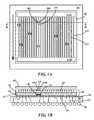
- FIG. 1Ais a top view and FIG. 1B is a cross-section view through line 1 B- 1 B of FIG. 1A illustrating an exemplary micro-channel cooled integrated circuit according to embodiments of the present invention
- FIG. 2Ais a top view and FIG. 2B is a cross-section view through line 2 B- 2 B of FIG. 2A illustrating an exemplary micro-channel cooled integrated circuit using a Peltier device according to embodiments of the present invention
- FIG. 3Ais a top view and FIG. 3B is a cross-section view through line 3 B- 3 B of FIG. 3A illustrating an exemplary micro-channel cooled integrated circuit using a heat sink according to embodiments of the present invention
- FIG. 4is a top view of an exemplary micro-channel cooled integrated circuit according to embodiments of the present invention.
- FIGS. 5A and 5Bare a cross-section through a micro-channel according to embodiments of the present invention.
- FIG. 6is a circuit diagram for controlling the flow of electro-rheological fluid through the micro-channels of FIG. 4 according to embodiments of the present invention
- FIG. 7is an alternate circuit diagram for controlling the flow of electro-rheological fluid through the micro-channels of FIG. 4 according to embodiments of the present invention.
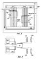
- FIG. 8is a top view of an exemplary micro-channel cooled integrated circuit according to an embodiment of the present invention.
- FIG. 9is a circuit diagram of a circuit for controlling the flow of electro-rheological fluid through the micro-channels of FIG. 8 according to an embodiment of the present invention.
- FIG. 10is a flowchart of a method for independent temperature control of a region of an integrated circuit according to an embodiment of the present invention.
- FIG. 11is a flowchart of a method for differential temperature control of a region of an integrated circuit according to an embodiment of the present invention.
- the embodiments of the present inventionprovide a plurality of micro-channels and electrodes formed in the backside of an integrated circuit chip for selective control of the flow of an electro-rheological (ER) cooling fluid through the micro-channels in regions of the integrated circuit chip.
- ERelectro-rheological
- An ER fluidcomprises a suspension of extremely fine non-conducting particles (e.g., about 0.1 micron to about 5 micron) in an electrically insulating fluid.
- the apparent viscosity of an ER fluidchanges reversibly by an order of up to 100,000 in response to an electric field.
- a typical ER fluidcan go from the consistency of a liquid (low viscosity) to that of a gel (high viscosity), and back, with response times on the order of milliseconds.
- An ER fluidcomprises particles mixed with a suspension liquid and may also include surfactants and additives.
- surfactantsthat may be added to ER fluids include, but are not limited to: block copolymers, glyserol mono-oleates, borax, hydrocarbon polymers, dodecyl alcohol, lead napthenate, metal hydrates, octyl alcohol, glycerol, sodium oleate, glyserol esters and tin oxide.
- additivesthat may be added to ER fluids include, but are not limited to: acetates, lactic acid, acetic acid, LiCl, alcohols, malic acid, aliphatic compounds, malonic acid, amines, metal chlorides, ammonium ion, mono-ethyl ether, butylamine, morpholine, calcium hydroxide, NaCl, diethylene glycol, NaOH, fluorides, octanoic acid, formic acid, oxalic acid, glycerine, pyruvic acid, hexylamine, trichloroasetic acid, KCl, water and KOH.
- Electro-rheological fluidsmust be shown to exhibit electro-rheological activity.
- FIG. 1Ais a top view and FIG. 1B is a cross-section view through line 1 B- 1 B of FIG. 1A illustrating an exemplary micro-channel cooled integrated circuit according to embodiments of the present invention.
- an integrated circuit chip 100mounted on a module (or carrier) 160 .
- Formed in the backside 107 of chip 100are first ER fluid reservoir 110 A connected to a second ER fluid reservoir 110 B by a plurality of micro-channels 115 .
- ER fluid reservoir 110 A and 110 B and micro-channels 115are integrally formed (e.g., etched) in the backside of chip 100 .
- Pairs of electrodes 120 A and 120 Bare formed on opposite sides of micro-channels 115 in selected locations.
- FIG. 1Ais a top view and FIG. 1B is a cross-section view through line 1 B- 1 B of FIG. 1A illustrating an exemplary micro-channel cooled integrated circuit according to embodiments of the present invention.
- an integrated circuit chip 100mounted on a
- chip 100comprises a semiconductor layer 125 separated from a supporting substrate 130 by a buried oxide (BOX) layer 135 .
- semiconductor layer 125is single crystal silicon.
- supporting substrate 130is single crystal silicon.
- Temperature sensing circuit 140monitors the local temperature of circuit 145 and controls a voltage differential applied to a corresponding pair of electrodes 120 A and 120 B to (i.e., those electrodes that control the flow of cooled ER fluid in adjacent to functional circuit 145 ) as described infra.
- Chip 100is physically mounted to and electrically connected to carrier 105 by solder bumps 150 .
- carrier 105is a multi-layer ceramic module. In one example, carrier 105 is a multi-layer printed circuit board (PCB).
- PCBprinted circuit board
- chip 100is formed a semiconductor-on-insulator (SOI) substrate.
- SOIsemiconductor-on-insulator
- the distance between the micro-channels and the devices of circuit 145 (e.g., field effect and/or bipolar transistors) in semiconductor layershould be a small as possible.
- the thickness of semiconductor layer 125is between about 2 microns and about 7 microns.
- the thickness of BOX layer 135is between about 0.1 microns and about 0.5 microns.
- the thickness of supporting substrate 130is between about 500 microns and about 750 microns.
- chip 100may be formed on a bulk silicon substrate (no buried oxide layer) having a thickness between about 600 microns and about 800 microns.
- FIG. 2Ais a top view and FIG. 2B is a cross-section view through line 2 B- 2 B of FIG. 2A illustrating an exemplary micro-channel cooled integrated circuit using a Peltier device according to embodiments of the present invention.
- Line 2 B- 2 Bpasses through first reservoir 110 A.
- lid 165 of FIG. 1Bhas been replaced with a heat conductive lid (e.g., metal) 165 B.
- a pair of Peltier devices 170 A and 170 Bhave been mounted on lid 165 A over first reservoir 110 A.
- Peltier device 170 Aincludes a cooling plate 172 A in contact with lid 165 B, a heat dissipating plate 174 A and an alternating N-doped/P-doped N semiconductor layer 173 A between plates 172 A and 1743 A.
- Peltier device 170 Bincludes a cooling plate 172 B in contact with lid 165 B, a heat dissipating plate 174 B and an alternating P-doped N-doped semiconductor layer 173 B between plates 172 B and 174 B.
- a pump 175is mounted to lid 165 B and pumps ER cooling fluid from second reservoir 110 B (see, for example, FIG. 1A ) through pipe 180 B to first reservoir 110 B through pipe 180 A.
- Peltier devices 170 A and 170 B and pump 175are supplied externally, through circuits in chip 100 may be used to turn the Peltier devices and pump on and off. In one example, for Peltier devices 170 A and 170 B and pump are wired to carrier 105 .
- FIG. 3Ais a top view and FIG. 3B is a cross-section view through line 3 B- 3 B of FIG. 3A illustrating an exemplary micro-channel cooled integrated circuit using a heat sink according to embodiments of the present invention.
- FIGS. 3A and 3Bare similar to FIGS. 2A and 2B respectively, except Peltier devices 170 A and 170 B of FIGS. 2A and 2B are replaced with heat sinks 185 A and 185 B respectively.
- FIG. 4is a top view of an exemplary micro-channel cooled integrated circuit according to embodiments of the present invention. For clarity, no lid or cooling devices are shown in FIG. 4 .
- FIG. 4gives an example, wherein micro-channels 115 are formed only in certain regions of the chip that need cooling.
- an integrated circuit chip 100 Aincludes a functional circuit (or region of chip 100 ) 190 and a temperature sensor circuit 195 . There are multiple micro-channels 115 passing over functional circuit 190 . Multiple electrodes 120 A and 120 B alternate between micro-channels 115 .
- All the electrodes 120 Aare wired together and all the electrodes 120 B are wired together so an electric field can be generated across all the micro-channels 115 simultaneously when a voltage differential is applied between electrodes 120 A and 120 B to shut off ER coolant fluid flow. While one set of circuit 190 , temperature sensor 195 and corresponding micro-channels 115 and electrodes 120 A/B are illustrated, there may be multiple independent such sets.
- FIGS. 5A and 5Bare a cross-section through a micro-channel according to embodiments of the present invention.
- micro-channel 115is a trench in supporting substrate 130 having a width W 1 and a length D 1 .
- W 1is between about 1 micron and about 10 microns.
- D 1is between about 1 micron and about 10 microns.
- the width and depth of micro-channel 115are at least 5 times the ER fluid particle size. If the width of the micro-channels becomes too large (e.g., exceeds about 50 microns), then the local temperature controlled regions become to large to reduce the otherwise large temperature gradients produced by circuits of the chip turning on and off without affecting the performance of those circuits.
- Electrodes 120 A/Bare formed in trenches 200 in supporting substrate 130 .
- Trenches 200have a dielectric liner to prevent cross-talk between different electrodes 120 A/B.
- electrodes 120 A/Bare formed within micro-channels 115 but isolated from supporting substrate 130 by dielectric liner 205 .
- FIG. 6is a circuit diagram for controlling the flow of ER fluid through the micro-channels of FIG. 4 according to embodiments of the present invention.
- temperature sensor circuit 195is directly connected to electrodes 120 A and 120 B.
- the temperature sensor circuitapplies a zero differential voltage between electrodes 120 A and 120 B generating an electric field that leaves the ER fluid liquid and allows coolant flow.
- T maxis about 85° C.
- a zero voltage differentialis generated by applying ground (0 volts) to both electrodes. In one example, a zero voltage differential is generated by applying the same positive or same negative voltage to both electrodes. In one example, a non-zero voltage differential is generated by applying ground (0 volts) to one electrode and a positive or negative voltage to the other electrode. In one example, a non-zero voltage differential is generated by applying different voltages to each of the electrodes. In one example, the voltage differential applied across electrode pairs 120 A/ 120 B is between about 1 volt and about 10 volts.
- FIG. 7is an alternate circuit diagram for controlling the flow of ER fluid through the micro-channels of FIG. 4 according to embodiments of the present invention.
- temperature sensor circuit 195only provides a control line to a control circuit 210 which is connected to electrodes 120 A and 120 B. This allows a differential voltage to be applied to the electrodes that may be greater than the temperature sensor or the functional circuit can provide.
- FIG. 8is a top view of an exemplary micro-channel cooled integrated circuit according to an embodiment of the present invention.
- FIG. 8gives an example, wherein micro-channels 115 are formed under a pair of circuits that are to be kept at the same temperature.
- an integrated circuit chip 100 Bincludes a first functional circuit 190 A (or first region of chip 100 ) and a first temperature sensor circuit 195 A.
- Multiple electrodes 120 A and 120 Balternate between micro-channels 115 A.
- integrated circuit chip 100 Bincludes a second functional circuit 190 B (or second region of chip 100 B) and a second temperature sensor circuit 195 B. There are multiple micro-channels 115 B passing over functional circuit 190 B. Multiple electrodes 120 C and 120 D alternate between micro-channels 115 B.
- Chip 100 Balso includes a control circuit 215 .
- FIG. 9is a circuit diagram of a circuit for controlling the flow of ER fluid through the micro-channels of FIG. 8 according to an embodiment of the present invention.
- temperature sensor circuits 195 A and 195 Bonly provide control lines to control circuit 215 which is connected to electrodes 120 A, 120 B, 120 C and 120 D.
- controller 215can apply: (1) a non-zero voltage differential across electrodes 120 A and 120 B and a zero-voltage differential across electrodes 120 C and 120 D, (2) a zero voltage differential across electrodes 120 A and 120 B and a non-zero voltage differential across electrodes 120 C and 120 D (3) a non-zero voltage differential across electrodes 120 A and 120 B and across electrodes 120 C and 120 D, and (4) a zero voltage differential across electrodes 120 A and 120 B and cross electrodes 120 C and 120 D. See description of FIG. 11 infra.
- connections between temperature sensors, control circuits and electrodes described supra with reference to FIGS. 6 , 7 and 9may be made (i) by conductive vias extending from the temperature sensor/control circuit through the chip or (ii) by connections made through the carrier (e.g., carrier 105 of FIG. 1B , 2 B, 3 B) to the lid (e.g., 165 of FIG. 1B , 165 B of FIGS. 2A and 3A ) than then to the electrodes ( 120 A/ 120 B of FIG. 4 or 120 A/ 120 B/ 120 C/ 120 D of FIG. 8 ).
- carriere.g., carrier 105 of FIG. 1B , 2 B, 3 B
- the lide.g., 165 of FIG. 1B , 165 B of FIGS. 2A and 3A
- FIG. 10is a flowchart of a method for independent temperature control of a region of an integrated circuit according to an embodiment of the present invention.
- step 230the integrated circuit chip is powered up and in step 235 the temperature of a region of the integrated circuit is measured.
- step 240if the measured temperature is less than a specified T max then, in step 245 , ER coolant fluid flow is blocked by applying an electric field across the micro-channels in the region (if an electric filed is not already applied) and the method loops back to step 230 .
- step 250ER coolant fluid flow is allowed by removing any electric field already applied or by continuing to not apply an electric field across the micro-channels in the region and the method loops back to step 235 . If in step 240 , the measured temperature is unchanged from the previous measurement, the method loops back to step 235 .
- the temperature measurement of step 235may be done on a periodic basis.
- the high/low temperature decision of step 240may be guard banded about a specified T max .
- a high reading set pointmay be T max +X ° C. and a low reading set point may be T max ⁇ Y ° C.
- a reading between T max +X ° C. and T max ⁇ Y ° C.is considered unchanged.
- X and Yare positive numbers. In one example, X and Y are independently between about 0.5° C. and about 10° C.
- FIG. 11is a flowchart of a method for differential temperature control of a region of an integrated circuit according to an embodiment of the present invention.
- step 255the integrated circuit chip is powered up and in step 260 the temperature of a first and second region of the integrated circuit is measured.
- the temperature measurements of step 260may be done on a periodic basis. If in step 265 , if both of the measured temperatures are unchanged (optionally within a preset limit of ⁇ W ° C.) from the previous measurements, the method loops back to step 260 . If, in step 260 , the measured temperatures have changed the method proceeds to step 270 . In step 270 it is determined if the two temperatures are the same (optionally within a preset limit of ⁇ Z ° C.).
- step 275(1) ER coolant fluid flow is blocked to the colder region by applying an electric field across the micro-channels in the region (if an electric filed is not already applied); (2) ER coolant fluid flow is allowed by removing any electric field already applied or by continuing not to apply an electric field across the micro-channels in the hotter region; and (3) the method loops back to step 260 .
- W and Zare positive numbers. In one example, W and Z are independently between about 0.5° C. and about 10° C.
- step 270the measured temperature are not the same (again optionally within a preset limit of ⁇ Y ° C.) the method proceeds to step 280 .
- step 280if the measured temperatures are less than a specified T max then, in step 285 , ER coolant fluid flow in both regions is blocked by applying an electric field across the micro-channels in the regions (if an electric filed is not already applied) and the method loops back to step 260 . If, in step 280 , the measured temperature is greater than the specified T max then, in step 290 , ER coolant fluid flow is allowed by removing any electric field already applied or by not applying an electric field across the micro-channels in the regions and the method loops back to step 260 .
- the above/below temperature decision of step 280may be guard banded about T max .
- a high reading set pointmay be T max +X ° C. and a low reading set point may be Tmax ⁇ Y ° C.
- a reading between T max +X ° C. and Tmax ⁇ Y ° C.is considered unchanged.
- steps 280 , 285 and 290may be eliminated and the “YES” branch of step 280 loops back to step 260 .
- the embodiments of the present inventionprovide methods for local temperature control of integrated circuits and locally temperature controlled electro-rheological micro-channel anisotropic cooled integrated circuits.
Landscapes
- Engineering & Computer Science (AREA)
- Microelectronics & Electronic Packaging (AREA)
- Physics & Mathematics (AREA)
- General Physics & Mathematics (AREA)
- Condensed Matter Physics & Semiconductors (AREA)
- Computer Hardware Design (AREA)
- Power Engineering (AREA)
- Thermal Sciences (AREA)
- Automation & Control Theory (AREA)
- Cooling Or The Like Of Semiconductors Or Solid State Devices (AREA)
Abstract
Description
Claims (21)
Priority Applications (1)
| Application Number | Priority Date | Filing Date | Title |
|---|---|---|---|
| US13/568,248US9052724B2 (en) | 2012-08-07 | 2012-08-07 | Electro-rheological micro-channel anisotropic cooled integrated circuits and methods thereof |
Applications Claiming Priority (1)
| Application Number | Priority Date | Filing Date | Title |
|---|---|---|---|
| US13/568,248US9052724B2 (en) | 2012-08-07 | 2012-08-07 | Electro-rheological micro-channel anisotropic cooled integrated circuits and methods thereof |
Publications (2)
| Publication Number | Publication Date |
|---|---|
| US20140043757A1 US20140043757A1 (en) | 2014-02-13 |
| US9052724B2true US9052724B2 (en) | 2015-06-09 |
Family
ID=50066036
Family Applications (1)
| Application Number | Title | Priority Date | Filing Date |
|---|---|---|---|
| US13/568,248Active2033-03-04US9052724B2 (en) | 2012-08-07 | 2012-08-07 | Electro-rheological micro-channel anisotropic cooled integrated circuits and methods thereof |
Country Status (1)
| Country | Link |
|---|---|
| US (1) | US9052724B2 (en) |
Cited By (5)
| Publication number | Priority date | Publication date | Assignee | Title |
|---|---|---|---|---|
| US9263366B2 (en)* | 2014-05-30 | 2016-02-16 | International Business Machines Corporation | Liquid cooling of semiconductor chips utilizing small scale structures |
| US9953899B2 (en) | 2015-09-30 | 2018-04-24 | Microfabrica Inc. | Micro heat transfer arrays, micro cold plates, and thermal management systems for cooling semiconductor devices, and methods for using and making such arrays, plates, and systems |
| US10317962B2 (en) | 2016-08-16 | 2019-06-11 | International Business Machines Corporation | Inducing heterogeneous microprocessor behavior using non-uniform cooling |
| US10558249B2 (en) | 2016-09-27 | 2020-02-11 | International Business Machines Corporation | Sensor-based non-uniform cooling |
| US12255123B2 (en) | 2015-09-30 | 2025-03-18 | Microfabrica Inc. | Micro heat transfer arrays, micro cold plates, and thermal management systems for semiconductor devices, and methods for using and making such arrays, plates, and systems |
Families Citing this family (10)
| Publication number | Priority date | Publication date | Assignee | Title |
|---|---|---|---|---|
| US20140262481A1 (en)* | 2013-03-15 | 2014-09-18 | Honeywell International Inc. | Self-aligning back plate for an electronic device |
| KR102291151B1 (en)* | 2014-11-03 | 2021-08-19 | 현대모비스 주식회사 | Cooling flow channel module for power changing device and power changing device having the same |
| FR3030112B1 (en) | 2014-12-12 | 2018-02-02 | Stmicroelectronics (Crolles 2) Sas | ASSEMBLING A CHIP OF INTEGRATED CIRCUITS AND A PLATE |
| US9373561B1 (en) | 2014-12-18 | 2016-06-21 | International Business Machines Corporation | Integrated circuit barrierless microfluidic channel |
| TWM512730U (en)* | 2015-08-20 | 2015-11-21 | Cooler Master Co Ltd | Water-cooled heat sink |
| JP6552450B2 (en)* | 2016-04-19 | 2019-07-31 | 三菱電機株式会社 | Semiconductor device |
| US10314203B1 (en)* | 2018-05-10 | 2019-06-04 | Juniper Networks, Inc | Apparatuses, systems, and methods for cooling electronic components |
| CN115050711B (en)* | 2022-08-15 | 2022-11-18 | 东莞市湃泊科技有限公司 | Heat dissipation substrate based on micro-channel |
| CN115799076B (en)* | 2023-02-03 | 2023-05-09 | 之江实验室 | Wafer system micro-channel manufacturing method capable of measuring flow velocity, pressure and temperature |
| CN116425110B (en)* | 2023-06-12 | 2023-09-19 | 之江实验室 | Wafer-level manufacturing method of high-temperature photoelectric pressure sensing chip with differential structure |
Citations (24)
| Publication number | Priority date | Publication date | Assignee | Title |
|---|---|---|---|---|
| US4573067A (en) | 1981-03-02 | 1986-02-25 | The Board Of Trustees Of The Leland Stanford Junior University | Method and means for improved heat removal in compact semiconductor integrated circuits |
| US4812251A (en)* | 1987-03-24 | 1989-03-14 | Er Fluid Developments Limited | Electro-rheological fluids/electric field responsive fluids |
| US4923057A (en)* | 1988-09-20 | 1990-05-08 | Lord Corporation | Electrorheological fluid composite structures |
| DE4224450A1 (en) | 1992-07-24 | 1994-02-03 | Deutsche Aerospace | Heat flux regulation of semiconductor device - using electro-rheological liq. for active temp. control |
| JPH08194545A (en) | 1994-11-17 | 1996-07-30 | Fujikura Kasei Co Ltd | Pressure control valve using electric rheology fluid |
| JPH0953610A (en) | 1995-08-18 | 1997-02-25 | Asahi Chem Ind Co Ltd | Control method of electric viscosity fluid |
| DE19725686A1 (en) | 1997-06-18 | 1998-12-24 | Schenck Ag Carl | Flow-rate control device |
| US5987196A (en)* | 1997-11-06 | 1999-11-16 | Micron Technology, Inc. | Semiconductor structure having an optical signal path in a substrate and method for forming the same |
| US6101715A (en) | 1995-04-20 | 2000-08-15 | Daimlerchrysler Ag | Microcooling device and method of making it |
| EP1109087A1 (en) | 1999-12-16 | 2001-06-20 | Carl Schenck Ag | Current control of electrorheological fluid |
| US6352144B1 (en)* | 1996-11-21 | 2002-03-05 | Advanced Fluid Systems Limited | Flow-control valve and damper |
| US20040113265A1 (en)* | 2002-12-17 | 2004-06-17 | Intel Corporation | Localized backside chip cooling with integrated smart valves |
| US6934154B2 (en) | 2003-03-31 | 2005-08-23 | Intel Corporation | Micro-channel heat exchangers and spreaders |
| US6981849B2 (en)* | 2002-12-18 | 2006-01-03 | Intel Corporation | Electro-osmotic pumps and micro-channels |
| US6992382B2 (en) | 2003-12-29 | 2006-01-31 | Intel Corporation | Integrated micro channels and manifold/plenum using separate silicon or low-cost polycrystalline silicon |
| US20060180300A1 (en)* | 2003-07-23 | 2006-08-17 | Lenehan Daniel J | Pump and fan control concepts in a cooling system |
| US7277284B2 (en) | 2004-03-30 | 2007-10-02 | Purdue Research Foundation | Microchannel heat sink |
| US7842248B2 (en)* | 2008-06-20 | 2010-11-30 | Silverbrook Research Pty Ltd | Microfluidic system comprising microfluidic pump, mixer or valve |
| US7891865B2 (en)* | 2006-05-03 | 2011-02-22 | International Business Machines Corporation | Structure for bolometric on-chip temperature sensor |
| US7940527B2 (en) | 2008-06-18 | 2011-05-10 | Brusa Elektronik Ag | Cooling system for electronic structural units |
| US20110151198A1 (en)* | 2008-08-21 | 2011-06-23 | Takashi Washizu | Micro-Channel Chip and Manufacturing Method and Micro-Channel Chip |
| US7975723B2 (en) | 2006-12-22 | 2011-07-12 | Palo Alto Research Center Incorporated | Controlling fluid through an array of fluid flow paths |
| WO2011113181A1 (en) | 2010-03-15 | 2011-09-22 | The Hong Kong University Of Science And Technology | Fluidic logic gates and apparatus for controlling flow of er fluid in a channel |
| US20120140416A1 (en)* | 2009-04-05 | 2012-06-07 | Dunan Microstaq, Inc. | Method and structure for optimizing heat exchanger performance |
- 2012
- 2012-08-07USUS13/568,248patent/US9052724B2/enactiveActive
Patent Citations (24)
| Publication number | Priority date | Publication date | Assignee | Title |
|---|---|---|---|---|
| US4573067A (en) | 1981-03-02 | 1986-02-25 | The Board Of Trustees Of The Leland Stanford Junior University | Method and means for improved heat removal in compact semiconductor integrated circuits |
| US4812251A (en)* | 1987-03-24 | 1989-03-14 | Er Fluid Developments Limited | Electro-rheological fluids/electric field responsive fluids |
| US4923057A (en)* | 1988-09-20 | 1990-05-08 | Lord Corporation | Electrorheological fluid composite structures |
| DE4224450A1 (en) | 1992-07-24 | 1994-02-03 | Deutsche Aerospace | Heat flux regulation of semiconductor device - using electro-rheological liq. for active temp. control |
| JPH08194545A (en) | 1994-11-17 | 1996-07-30 | Fujikura Kasei Co Ltd | Pressure control valve using electric rheology fluid |
| US6101715A (en) | 1995-04-20 | 2000-08-15 | Daimlerchrysler Ag | Microcooling device and method of making it |
| JPH0953610A (en) | 1995-08-18 | 1997-02-25 | Asahi Chem Ind Co Ltd | Control method of electric viscosity fluid |
| US6352144B1 (en)* | 1996-11-21 | 2002-03-05 | Advanced Fluid Systems Limited | Flow-control valve and damper |
| DE19725686A1 (en) | 1997-06-18 | 1998-12-24 | Schenck Ag Carl | Flow-rate control device |
| US5987196A (en)* | 1997-11-06 | 1999-11-16 | Micron Technology, Inc. | Semiconductor structure having an optical signal path in a substrate and method for forming the same |
| EP1109087A1 (en) | 1999-12-16 | 2001-06-20 | Carl Schenck Ag | Current control of electrorheological fluid |
| US20040113265A1 (en)* | 2002-12-17 | 2004-06-17 | Intel Corporation | Localized backside chip cooling with integrated smart valves |
| US6981849B2 (en)* | 2002-12-18 | 2006-01-03 | Intel Corporation | Electro-osmotic pumps and micro-channels |
| US6934154B2 (en) | 2003-03-31 | 2005-08-23 | Intel Corporation | Micro-channel heat exchangers and spreaders |
| US20060180300A1 (en)* | 2003-07-23 | 2006-08-17 | Lenehan Daniel J | Pump and fan control concepts in a cooling system |
| US6992382B2 (en) | 2003-12-29 | 2006-01-31 | Intel Corporation | Integrated micro channels and manifold/plenum using separate silicon or low-cost polycrystalline silicon |
| US7277284B2 (en) | 2004-03-30 | 2007-10-02 | Purdue Research Foundation | Microchannel heat sink |
| US7891865B2 (en)* | 2006-05-03 | 2011-02-22 | International Business Machines Corporation | Structure for bolometric on-chip temperature sensor |
| US7975723B2 (en) | 2006-12-22 | 2011-07-12 | Palo Alto Research Center Incorporated | Controlling fluid through an array of fluid flow paths |
| US7940527B2 (en) | 2008-06-18 | 2011-05-10 | Brusa Elektronik Ag | Cooling system for electronic structural units |
| US7842248B2 (en)* | 2008-06-20 | 2010-11-30 | Silverbrook Research Pty Ltd | Microfluidic system comprising microfluidic pump, mixer or valve |
| US20110151198A1 (en)* | 2008-08-21 | 2011-06-23 | Takashi Washizu | Micro-Channel Chip and Manufacturing Method and Micro-Channel Chip |
| US20120140416A1 (en)* | 2009-04-05 | 2012-06-07 | Dunan Microstaq, Inc. | Method and structure for optimizing heat exchanger performance |
| WO2011113181A1 (en) | 2010-03-15 | 2011-09-22 | The Hong Kong University Of Science And Technology | Fluidic logic gates and apparatus for controlling flow of er fluid in a channel |
Cited By (11)
| Publication number | Priority date | Publication date | Assignee | Title |
|---|---|---|---|---|
| US9263366B2 (en)* | 2014-05-30 | 2016-02-16 | International Business Machines Corporation | Liquid cooling of semiconductor chips utilizing small scale structures |
| US20160064307A1 (en)* | 2014-05-30 | 2016-03-03 | International Business Machines Corporation | Liquid cooling of semiconductor chips utilizing small scale structures |
| US9564386B2 (en)* | 2014-05-30 | 2017-02-07 | International Business Machines Corporation | Semiconductor package with structures for cooling fluid retention |
| US9953899B2 (en) | 2015-09-30 | 2018-04-24 | Microfabrica Inc. | Micro heat transfer arrays, micro cold plates, and thermal management systems for cooling semiconductor devices, and methods for using and making such arrays, plates, and systems |
| US10665530B2 (en) | 2015-09-30 | 2020-05-26 | Microfabrica Inc. | Micro heat transfer arrays, micro cold plates, and thermal management systems for cooling semiconductor devices, and methods for using and making such arrays, plates, and systems |
| US10957624B2 (en) | 2015-09-30 | 2021-03-23 | Microfabrica Inc. | Micro heat transfer arrays, micro cold plates, and thermal management systems for cooling semiconductor devices, and methods for using and making such arrays, plates, and systems |
| US11456235B1 (en) | 2015-09-30 | 2022-09-27 | Microfabrica Inc. | Micro heat transfer arrays, micro cold plates, and thermal management systems for cooling semiconductor devices, and methods for using and making such arrays, plates, and systems |
| US12255123B2 (en) | 2015-09-30 | 2025-03-18 | Microfabrica Inc. | Micro heat transfer arrays, micro cold plates, and thermal management systems for semiconductor devices, and methods for using and making such arrays, plates, and systems |
| US10317962B2 (en) | 2016-08-16 | 2019-06-11 | International Business Machines Corporation | Inducing heterogeneous microprocessor behavior using non-uniform cooling |
| US10613603B2 (en) | 2016-08-16 | 2020-04-07 | International Business Machines Corporation | Inducing heterogeneous microprocessor behavior using non-uniform cooling |
| US10558249B2 (en) | 2016-09-27 | 2020-02-11 | International Business Machines Corporation | Sensor-based non-uniform cooling |
Also Published As
| Publication number | Publication date |
|---|---|
| US20140043757A1 (en) | 2014-02-13 |
Similar Documents
| Publication | Publication Date | Title |
|---|---|---|
| US9052724B2 (en) | Electro-rheological micro-channel anisotropic cooled integrated circuits and methods thereof | |
| US9257366B2 (en) | Auto-compensating temperature valve controller for electro-rheological fluid micro-channel cooled integrated circuit | |
| US7492594B2 (en) | Electronic circuit modules cooling | |
| Al-Neama et al. | An experimental and numerical investigation of the use of liquid flow in serpentine microchannels for microelectronics cooling | |
| Prasher et al. | Nano and Micro Technology-Based Next-Generation Package-Level Cooling Solutions. | |
| TWI242865B (en) | Electro-osmotic pumps and micro-channels | |
| CN104425408B (en) | Cooling system for 3D IC | |
| US20140158334A1 (en) | Thermal management system with variable-volume material | |
| US8826984B2 (en) | Method and apparatus of heat dissipaters for electronic components in downhole tools | |
| US11297745B2 (en) | Active thermal management system for electronic devices and method of achieving device-to-device isothermalization | |
| CN103515337A (en) | Heat dissipation system for power module | |
| CN103413790B (en) | A kind of encapsulating structure of integrated power control unit | |
| CN107655928A (en) | A thermoelectric performance testing device in a large temperature difference environment | |
| Yuki et al. | Thermal management of automotive SiC-based on-board inverter with 500 W/cm2 in heat flux, and Two-phase immersion cooling by breathing phenomenon spontaneously induced by lotus porous copper jointed onto a grooved heat transfer surface | |
| Kesarkar et al. | How TIM impacts thermal performance of electronics:: A thermal point of view study to understand impact of Thermal Interface Material (TIM) | |
| Vladimirova et al. | Drift region integrated microchannels for direct cooling of power electronic devices: Advantages and limitations | |
| CN102548367A (en) | Small passageway liquid cooling base board of power electronic integration module with double-trapezoid cross section fins | |
| Vaisband et al. | Thermal conduction path analysis in 3-D ICs | |
| KR20190134438A (en) | Boiling cooling system | |
| US20060185836A1 (en) | Thermally coupled surfaces having controlled minimum clearance | |
| KR102341614B1 (en) | computer case | |
| CN104934388A (en) | Aluminum silicon carbide composite radiating structure | |
| Hu et al. | Numerical simulation and optimization of heat dissipation structure for high power insulated gate bipolar transistor (IGBT) | |
| Deng et al. | Numerical and experimental study of an integrated thermoelectric active cooling system for ultra-high temperature downhole electronics | |
| CN205546391U (en) | Heat radiation fin |
Legal Events
| Date | Code | Title | Description |
|---|---|---|---|
| AS | Assignment | Owner name:INTERNATIONAL BUSINESS MACHINES CORPORATION, NEW Y Free format text:ASSIGNMENT OF ASSIGNORS INTEREST;ASSIGNORS:BERNSTEIN, KERRY;GOODNOW, KENNETH J.;OGILVIE, CLARENCE R.;SIGNING DATES FROM 20120801 TO 20120806;REEL/FRAME:028736/0789 | |
| STCF | Information on status: patent grant | Free format text:PATENTED CASE | |
| AS | Assignment | Owner name:GLOBALFOUNDRIES U.S. 2 LLC, NEW YORK Free format text:ASSIGNMENT OF ASSIGNORS INTEREST;ASSIGNOR:INTERNATIONAL BUSINESS MACHINES CORPORATION;REEL/FRAME:036550/0001 Effective date:20150629 | |
| AS | Assignment | Owner name:GLOBALFOUNDRIES INC., CAYMAN ISLANDS Free format text:ASSIGNMENT OF ASSIGNORS INTEREST;ASSIGNORS:GLOBALFOUNDRIES U.S. 2 LLC;GLOBALFOUNDRIES U.S. INC.;REEL/FRAME:036779/0001 Effective date:20150910 | |
| MAFP | Maintenance fee payment | Free format text:PAYMENT OF MAINTENANCE FEE, 4TH YEAR, LARGE ENTITY (ORIGINAL EVENT CODE: M1551); ENTITY STATUS OF PATENT OWNER: LARGE ENTITY Year of fee payment:4 | |
| AS | Assignment | Owner name:WILMINGTON TRUST, NATIONAL ASSOCIATION, DELAWARE Free format text:SECURITY AGREEMENT;ASSIGNOR:GLOBALFOUNDRIES INC.;REEL/FRAME:049490/0001 Effective date:20181127 | |
| AS | Assignment | Owner name:GLOBALFOUNDRIES U.S. INC., CALIFORNIA Free format text:ASSIGNMENT OF ASSIGNORS INTEREST;ASSIGNOR:GLOBALFOUNDRIES INC.;REEL/FRAME:054633/0001 Effective date:20201022 | |
| AS | Assignment | Owner name:GLOBALFOUNDRIES INC., CAYMAN ISLANDS Free format text:RELEASE BY SECURED PARTY;ASSIGNOR:WILMINGTON TRUST, NATIONAL ASSOCIATION;REEL/FRAME:054636/0001 Effective date:20201117 | |
| AS | Assignment | Owner name:GLOBALFOUNDRIES U.S. INC., NEW YORK Free format text:RELEASE BY SECURED PARTY;ASSIGNOR:WILMINGTON TRUST, NATIONAL ASSOCIATION;REEL/FRAME:056987/0001 Effective date:20201117 | |
| MAFP | Maintenance fee payment | Free format text:PAYMENT OF MAINTENANCE FEE, 8TH YEAR, LARGE ENTITY (ORIGINAL EVENT CODE: M1552); ENTITY STATUS OF PATENT OWNER: LARGE ENTITY Year of fee payment:8 |