US9052717B1 - Watercraft speed control device - Google Patents
Watercraft speed control deviceDownload PDFInfo
- Publication number
- US9052717B1 US9052717B1US12/965,556US96555610AUS9052717B1US 9052717 B1US9052717 B1US 9052717B1US 96555610 AUS96555610 AUS 96555610AUS 9052717 B1US9052717 B1US 9052717B1
- Authority
- US
- United States
- Prior art keywords
- watercraft
- velocity
- engine
- engine speed
- algorithm
- Prior art date
- Legal status (The legal status is an assumption and is not a legal conclusion. Google has not performed a legal analysis and makes no representation as to the accuracy of the status listed.)
- Expired - Lifetime
Links
Images


Classifications
- G—PHYSICS
- G05—CONTROLLING; REGULATING
- G05D—SYSTEMS FOR CONTROLLING OR REGULATING NON-ELECTRIC VARIABLES
- G05D1/00—Control of position, course, altitude or attitude of land, water, air or space vehicles, e.g. using automatic pilots
- G05D1/02—Control of position or course in two dimensions
- G05D1/0206—Control of position or course in two dimensions specially adapted to water vehicles
- B—PERFORMING OPERATIONS; TRANSPORTING
- B63—SHIPS OR OTHER WATERBORNE VESSELS; RELATED EQUIPMENT
- B63B—SHIPS OR OTHER WATERBORNE VESSELS; EQUIPMENT FOR SHIPPING
- B63B49/00—Arrangements of nautical instruments or navigational aids
- B—PERFORMING OPERATIONS; TRANSPORTING
- B60—VEHICLES IN GENERAL
- B60W—CONJOINT CONTROL OF VEHICLE SUB-UNITS OF DIFFERENT TYPE OR DIFFERENT FUNCTION; CONTROL SYSTEMS SPECIALLY ADAPTED FOR HYBRID VEHICLES; ROAD VEHICLE DRIVE CONTROL SYSTEMS FOR PURPOSES NOT RELATED TO THE CONTROL OF A PARTICULAR SUB-UNIT
- B60W10/00—Conjoint control of vehicle sub-units of different type or different function
- B60W10/04—Conjoint control of vehicle sub-units of different type or different function including control of propulsion units
- B60W10/06—Conjoint control of vehicle sub-units of different type or different function including control of propulsion units including control of combustion engines
- B—PERFORMING OPERATIONS; TRANSPORTING
- B60—VEHICLES IN GENERAL
- B60W—CONJOINT CONTROL OF VEHICLE SUB-UNITS OF DIFFERENT TYPE OR DIFFERENT FUNCTION; CONTROL SYSTEMS SPECIALLY ADAPTED FOR HYBRID VEHICLES; ROAD VEHICLE DRIVE CONTROL SYSTEMS FOR PURPOSES NOT RELATED TO THE CONTROL OF A PARTICULAR SUB-UNIT
- B60W10/00—Conjoint control of vehicle sub-units of different type or different function
- B60W10/04—Conjoint control of vehicle sub-units of different type or different function including control of propulsion units
- B60W10/08—Conjoint control of vehicle sub-units of different type or different function including control of propulsion units including control of electric propulsion units, e.g. motors or generators
- G—PHYSICS
- G01—MEASURING; TESTING
- G01C—MEASURING DISTANCES, LEVELS OR BEARINGS; SURVEYING; NAVIGATION; GYROSCOPIC INSTRUMENTS; PHOTOGRAMMETRY OR VIDEOGRAMMETRY
- G01C21/00—Navigation; Navigational instruments not provided for in groups G01C1/00 - G01C19/00
- G01C21/10—Navigation; Navigational instruments not provided for in groups G01C1/00 - G01C19/00 by using measurements of speed or acceleration
- G01C21/12—Navigation; Navigational instruments not provided for in groups G01C1/00 - G01C19/00 by using measurements of speed or acceleration executed aboard the object being navigated; Dead reckoning
- G01C21/16—Navigation; Navigational instruments not provided for in groups G01C1/00 - G01C19/00 by using measurements of speed or acceleration executed aboard the object being navigated; Dead reckoning by integrating acceleration or speed, i.e. inertial navigation
- G01C21/183—Compensation of inertial measurements, e.g. for temperature effects
- G01C21/188—Compensation of inertial measurements, e.g. for temperature effects for accumulated errors, e.g. by coupling inertial systems with absolute positioning systems
- B—PERFORMING OPERATIONS; TRANSPORTING
- B60—VEHICLES IN GENERAL
- B60L—PROPULSION OF ELECTRICALLY-PROPELLED VEHICLES; SUPPLYING ELECTRIC POWER FOR AUXILIARY EQUIPMENT OF ELECTRICALLY-PROPELLED VEHICLES; ELECTRODYNAMIC BRAKE SYSTEMS FOR VEHICLES IN GENERAL; MAGNETIC SUSPENSION OR LEVITATION FOR VEHICLES; MONITORING OPERATING VARIABLES OF ELECTRICALLY-PROPELLED VEHICLES; ELECTRIC SAFETY DEVICES FOR ELECTRICALLY-PROPELLED VEHICLES
- B60L2240/00—Control parameters of input or output; Target parameters
- B60L2240/60—Navigation input
- B60L2240/62—Vehicle position
- B60L2240/622—Vehicle position by satellite navigation
- B—PERFORMING OPERATIONS; TRANSPORTING
- B60—VEHICLES IN GENERAL
- B60W—CONJOINT CONTROL OF VEHICLE SUB-UNITS OF DIFFERENT TYPE OR DIFFERENT FUNCTION; CONTROL SYSTEMS SPECIALLY ADAPTED FOR HYBRID VEHICLES; ROAD VEHICLE DRIVE CONTROL SYSTEMS FOR PURPOSES NOT RELATED TO THE CONTROL OF A PARTICULAR SUB-UNIT
- B60W2520/00—Input parameters relating to overall vehicle dynamics
- B60W2520/10—Longitudinal speed
- B—PERFORMING OPERATIONS; TRANSPORTING
- B60—VEHICLES IN GENERAL
- B60W—CONJOINT CONTROL OF VEHICLE SUB-UNITS OF DIFFERENT TYPE OR DIFFERENT FUNCTION; CONTROL SYSTEMS SPECIALLY ADAPTED FOR HYBRID VEHICLES; ROAD VEHICLE DRIVE CONTROL SYSTEMS FOR PURPOSES NOT RELATED TO THE CONTROL OF A PARTICULAR SUB-UNIT
- B60W2710/00—Output or target parameters relating to a particular sub-units
- B60W2710/06—Combustion engines, Gas turbines
- B60W2710/0644—Engine speed
- B—PERFORMING OPERATIONS; TRANSPORTING
- B60—VEHICLES IN GENERAL
- B60W—CONJOINT CONTROL OF VEHICLE SUB-UNITS OF DIFFERENT TYPE OR DIFFERENT FUNCTION; CONTROL SYSTEMS SPECIALLY ADAPTED FOR HYBRID VEHICLES; ROAD VEHICLE DRIVE CONTROL SYSTEMS FOR PURPOSES NOT RELATED TO THE CONTROL OF A PARTICULAR SUB-UNIT
- B60W2710/00—Output or target parameters relating to a particular sub-units
- B60W2710/06—Combustion engines, Gas turbines
- B60W2710/0666—Engine torque
- F—MECHANICAL ENGINEERING; LIGHTING; HEATING; WEAPONS; BLASTING
- F02—COMBUSTION ENGINES; HOT-GAS OR COMBUSTION-PRODUCT ENGINE PLANTS
- F02D—CONTROLLING COMBUSTION ENGINES
- F02D2250/00—Engine control related to specific problems or objectives
- F02D2250/18—Control of the engine output torque
- G—PHYSICS
- G01—MEASURING; TESTING
- G01C—MEASURING DISTANCES, LEVELS OR BEARINGS; SURVEYING; NAVIGATION; GYROSCOPIC INSTRUMENTS; PHOTOGRAMMETRY OR VIDEOGRAMMETRY
- G01C21/00—Navigation; Navigational instruments not provided for in groups G01C1/00 - G01C19/00
- G01C21/10—Navigation; Navigational instruments not provided for in groups G01C1/00 - G01C19/00 by using measurements of speed or acceleration
- G01C21/12—Navigation; Navigational instruments not provided for in groups G01C1/00 - G01C19/00 by using measurements of speed or acceleration executed aboard the object being navigated; Dead reckoning
- G01C21/16—Navigation; Navigational instruments not provided for in groups G01C1/00 - G01C19/00 by using measurements of speed or acceleration executed aboard the object being navigated; Dead reckoning by integrating acceleration or speed, i.e. inertial navigation
- Y—GENERAL TAGGING OF NEW TECHNOLOGICAL DEVELOPMENTS; GENERAL TAGGING OF CROSS-SECTIONAL TECHNOLOGIES SPANNING OVER SEVERAL SECTIONS OF THE IPC; TECHNICAL SUBJECTS COVERED BY FORMER USPC CROSS-REFERENCE ART COLLECTIONS [XRACs] AND DIGESTS
- Y02—TECHNOLOGIES OR APPLICATIONS FOR MITIGATION OR ADAPTATION AGAINST CLIMATE CHANGE
- Y02T—CLIMATE CHANGE MITIGATION TECHNOLOGIES RELATED TO TRANSPORTATION
- Y02T10/00—Road transport of goods or passengers
- Y02T10/60—Other road transportation technologies with climate change mitigation effect
- Y02T10/72—Electric energy management in electromobility
- Y—GENERAL TAGGING OF NEW TECHNOLOGICAL DEVELOPMENTS; GENERAL TAGGING OF CROSS-SECTIONAL TECHNOLOGIES SPANNING OVER SEVERAL SECTIONS OF THE IPC; TECHNICAL SUBJECTS COVERED BY FORMER USPC CROSS-REFERENCE ART COLLECTIONS [XRACs] AND DIGESTS
- Y02—TECHNOLOGIES OR APPLICATIONS FOR MITIGATION OR ADAPTATION AGAINST CLIMATE CHANGE
- Y02T—CLIMATE CHANGE MITIGATION TECHNOLOGIES RELATED TO TRANSPORTATION
- Y02T90/00—Enabling technologies or technologies with a potential or indirect contribution to GHG emissions mitigation
- Y02T90/10—Technologies relating to charging of electric vehicles
- Y02T90/16—Information or communication technologies improving the operation of electric vehicles
Definitions
- the present inventionpertains to the field of water sports and boating.
- Competitors in trick, jump, and slalom ski and wakeboard eventsrequire tow boats capable of consistent and accurate speed control.
- Intricate freestyle tricks, jumps, and successful completion of slalom runsrequire passes through a competition water course at precisely the same speed at which the events were practiced by the competitors. Some events require that a pass through a course be made at a specified speed.
- Such requirementsare made difficult by the fact that typical watercraft Pitot tube and paddle wheel speedometers are inaccurate and measure speed over water instead of speed over land, and wind, wave, and skier loading conditions constantly vary throughout a competition pass.
- Marine transportation in generalsuffers from the lack of accurate vessel speed control.
- the schedules of ocean-going vessels for which exact arrival times are required, for example,are vulnerable to the vagaries of wind, waves, and changing hull displacement due to fuel depletion.
- the present inventionprovides consistent, accurate control of watercraft speed over land. It utilizes velocity measuring device and an inertia based measurement device technology to precisely monitor watercraft velocity over land. It utilizes dynamic monitoring and dynamic updating of engine control data in order to be responsive to real-time conditions such as wind, waves, and loading.
- FIG. 1is a flow diagram of an embodiment of the present invention.
- FIG. 2is a flow chart of the steady state timer algorithm used in the embodiment.
- FIG. 3is a schematic of a watercraft utilizing an embodiment of the present invention.
- FIG. 4is a graphical representation of the engine speed and boat speed data shown in the tables herein.
- FIG. 5is a flow diagram of an alternate embodiment of the present invention.
- FIG. 6is a flow diagram of another embodiment of the present invention.
- FIG. 7is a flow diagram of an alternate embodiment of the present invention.
- FIG. 8is a flow diagram of another embodiment of the present invention.
- FIG. 9is a flow diagram of another embodiment of the present invention.
- FIG. 10is a flow diagram of an alternate embodiment of the present invention.
- FIG. 11is a flow diagram of another embodiment of the present invention.
- FIG. 12is a flow diagram of an alternate embodiment of the present invention.
- FIG. 13is a flow diagram of another embodiment of the present invention.
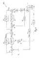
- the present inventionis an electronic closed-loop feedback system that controls the actual angular velocity ⁇ a of a boat propeller, and, indirectly, the actual over land velocity v a of the watercraft propelled by that propeller.
- the systemhas various configurations with one embodiment including a velocity measuring device, an inertia-based measuring device, at least two conversion algorithms, and engine speed controls.
- Other configurationsinclude a global positioning satellite (GPS) velocity measurement device, a marine engine speed tachometer, comparators, conversion algorithms, and engine speed controls.
- GPSglobal positioning satellite
- a GPS deviceis one of the category of commonly understood instruments that use satellites to determine the substantially precise global position and velocity of an object. Such position and velocity measurements can be used in conjunction with timers to determine an object's instantaneous velocity and average velocity between two points.
- a velocity measuring deviceis one of a category of commonly understood instruments that is capable of measuring the velocity of an object for example, a GPS device, a paddle wheel, or a pitot tube.
- An inertia based measurement deviceis one of a category of commonly understood instruments that is capable of measuring the acceleration of an object. The velocity of an object can be calculated by integrating the acceleration of an object over time.
- Engine speedrefers to angular velocity, generally measured with a device herein referred to as a tachometer.
- a comparatoris any analog or digital electrical, electronic, mechanical, hydraulic, or fluidic device capable of determining the sum of or difference between two input parameters, or the value of an input relative to a predetermined standard.
- An algorithmis any analog or digital electrical, electronic, mechanical, hydraulic, or fluidic device capable of performing a computational process. The algorithms disclosed herein can be performed on any number of devices commonly called microprocessors or microcontrollers, examples of which include the Motorola® MPC555 and the Texas Instruments® TMS320.
- GPS device 10measures the actual velocity v a of a watercraft 50 .
- the GPS output v GPSis compared in first comparator 12 to predetermined velocity v d .
- Comparator 12 output velocity error ⁇ vis input to an algorithm 14 that converts ⁇ v to engine speed correction ⁇ c that is input to a second comparator 16 .
- Predetermined velocity v dis input to an algorithm 18 the output of which is ⁇ adapt , a value of engine speed adaptively determined to be the engine speed necessary to propel watercraft 50 at predetermined velocity v d under the prevailing conditions of wind, waves, and watercraft loading, trim angle, and attitude.
- engine speed correction ⁇ c and engine speed ⁇ adapt in comparator 16results in the total desired engine speed ⁇ d that is input to a third comparator 20 .
- a sensor 24one of many types of commonly understood tachometers, detects the actual angular velocity ⁇ a of a driveshaft from an engine 53 of watercraft 50 and sends it to third comparator 20 .
- comparator 20actual angular velocity ⁇ a and total desired engine speed ⁇ d are compared for engine speed error ⁇ ⁇ that is input to an algorithm 26 .
- engine speed error ⁇ ⁇is converted into engine torque correction ⁇ c .
- Total desired engine speed ⁇ dis also input to an algorithm 22 the output of which is ⁇ adapt , a value of engine torque adaptively determined to be the engine torque necessary to operate watercraft engine 53 at total desired engine speed ⁇ d .
- Calculated desired engine torque ⁇ dis input to controller 30 that drives a throttle control capable of producing in engine 53 a torque substantially equal to calculated desired engine torque ⁇ d .
- the algorithms 14 and 26could include any common or advanced control loop transfer function including, but not limited to, series, parallel, ideal, interacting, noninteracting, analog, classical, and Laplace types.
- K p , K d , and K lare, respectively, the appropriate proportional, derivative, and integral gains.
- the algorithms 18 and 22provide dynamically adaptive mapping between an input and an output. Such mapping can be described as self-modifying.
- the inputs to the algorithms 18 and 22are, respectively, predetermined velocity v d and total desired engine speed ⁇ d .
- the outputs of the algorithms 18 and 22are, respectively, engine speed ⁇ adapt and engine torque ⁇ adapt .
- the self-modifying correlations of algorithms 18 and 22may be programmed during replicated calibration operations of a watercraft through a range of velocities in a desired set of ambient conditions including, but not limited to, wind, waves, and watercraft loading, trim angle, and attitude. Data triplets of watercraft velocity, engine speed, and engine torque are monitored with GPS technology and other commonly understood devices and fed to algorithms 18 and 22 during the calibration operations.
- a substantially instantaneous estimate of the engine speed required to obtain a desired watercraft velocity and a substantially instantaneous estimate of the engine torque required to obtain a desired engine speedcan be fed to the engine speed and torque control loops, even in the absence of watercraft velocity or engine speed departures from desired values, in which cases the outputs of algorithms 14 and 26 may be zero.
- no adaptive data point of watercraft velocity, engine speed, or engine torque described aboveis programmed into algorithms 18 or 22 until it has attained a steady state condition as diagrammed in FIG. 2 .
- a timercompares watercraft velocity error ⁇ v , engine speed error ⁇ ⁇ , the time rate of change of actual watercraft velocity v a , and the time rate of change of actual engine speed ⁇ a to predetermined tolerance values.
- the last block on the FIG. 2 flowchartrepresents a correction to speed control algorithm 14 .
- the correctionmay be used to smooth iterations that may be present if algorithm 14 uses integrator action.
- Thisis the same updating equation that is used in algorithm 18 , and it is derived in the same manner as is illustrated in FIG. 2 .
- the smoothing technique described abovemay be used to counter the effects of integrator action in algorithm 26 .
- the substantially instantaneous estimates of engine speed and torque derived from algorithms 18 and 22require interpolation among the discrete values programmed during watercraft calibration operation.
- interpolation schemesincluding high-order and Lagrangian polynomials, but the present embodiment utilizes a linear interpolation scheme.
- algorithm 18employs linear interpolation to calculate a value of ⁇ adapt for any predetermined velocity v d .
- ⁇ adapt⁇ m +[( v d ⁇ v m )/( v m+1 ⁇ v m )]( ⁇ m+1 ⁇ m ).
- algorithm 22could also utilize any of several interpolation schemes, and is not constrained to duplication of algorithm 18 , in the present embodiment of the present invention, algorithm 22 calculates ⁇ adapt using the same linear interpolation that algorithm 18 uses to calculate ⁇ adapt .
- algorithm 22calculates ⁇ adapt using the same linear interpolation that algorithm 18 uses to calculate ⁇ adapt .
- adaptive update algorithm 18when using a linearly interpolated table of values as the interpolation embodiment, the following procedure can be followed:
- Adaptive algorithms 18 and 22are not required for operation of the present invention, but they are incorporated into the embodiment. Aided by commonly understood integrators, algorithms 14 and 26 are capable of ultimate control of a watercraft's velocity. However, the additional adaptive control provided by algorithms 18 and 22 enhances the overall transient response of system 100 .
- the following tableis an example of the velocity vs. engine speed adaptive table as it might be initialized from the factory. This table is a simple linear table which starts at zero velocity and extends to the maximum velocity of the boat (60 kph) at which the maximum engine speed rating (6000 rpm) is also reached:
- FIG. 4is a graphical representation of the data in the preceding tables.
- Controller 30(see FIG. 1 ) is the interface between calculated desired engine torque ⁇ d and the throttle control that causes the ultimate changes in engine speed. Controller 30 may interpose any number of relationships between calculated desired engine torque ⁇ d and engine speed, but the embodiment of the present invention utilizes a direct proportionality. Other embodiments of the present invention could use controller 30 to adjust engine parameters other than throttle setting. Such parameters could include spark timing, fuel flow rate, or air flow rate.
- the embodiment of the present inventioncontemplates a boat with a single speed transmission and a fixed pitch propeller.
- An alternate embodiment of the present inventioncould be used with boats having variable transmissions and/or variable pitch propellers. In these alternate embodiments, the controller 30 could adjust the transmission, pitch of the propeller, throttle setting, or a combination thereof.
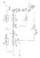
- FIG. 3illustrates how an operator of watercraft 50 controls the speed of engine 53 and propeller 51 .
- the operatorsupplies predetermined and desired velocity v d through a control input device such as control keypad and display unit 59 to control module 65 that houses the algorithms and comparators of system 100 .
- GPS measurements from device 10 and predetermined velocity v d valuesare sent to control module 65 via communications link 55 .
- Communication link 57feeds engine speed measurements from a tachometer to control module 65 .
- System 100may be overridden at any time through operator control of manual throttle control 61 that controls engine throttle 63 .
- FIG. 5Diagrammed in FIG. 5 is feedback system 101 which is an alternate embodiment of the present invention.
- the comparator 12is removed from system 101 .
- the velocity measurement determined by the GPS device 10is fed directly to algorithm 14 .
- Algorithm 14is modified to incorporate predetermined velocity v d and GPS output v GPS in the calculation to determine engine speed correction ⁇ c .
- system 102incorporates an inertia measuring device 11 , an algorithm 15 , an algorithm 17 , and a velocity measuring device 31 .
- the inertia measuring device 11measures the actual acceleration a Acc of a watercraft 50 and the velocity measuring device 31 measures the actual velocity v VMD of the same watercraft 50 .
- algorithm 14is modified to incorporate predetermined velocity v d , observed velocity v OBS , actual acceleration a Acc , and predetermined acceleration a d in the calculation to determine engine speed correction ⁇ c .
- the algorithms 14 and 26could include any common or advanced control loop transfer function including, but not limited to, series, parallel, ideal, interacting, noninteracting, analog, classical, and Laplace types.
- K p , K d , and K iare, respectively, the appropriate proportional, derivative, and integral gains.
- FIG. 8Diagrammed in FIG. 8 is feedback system 103 which is an alternate embodiment of the present invention.
- system 103incorporates an inertia measuring device 11 , and a velocity measuring device 31 .
- the inertia measuring device 11measures the actual acceleration a Acc of a watercraft 50 and the velocity measuring device 31 measures the actual velocity v VMD of the same watercraft 50 .
- the algorithm 14is modified to incorporate desired velocity v d , desired acceleration a d , actual acceleration a Acc , and actual velocity v VMD in the calculation to determine engine speed correction ⁇ c .
- FIG. 10Diagrammed in FIG. 10 is feedback system 106 which is another embodiment of the present invention.
- system 106incorporates an inertia measuring device 11 without a velocity measuring device.
- the inertia measuring device 11measures the actual acceleration a Acc of a watercraft 50 .
- the algorithm 14is modified to incorporate desired velocity v d , desired acceleration a d , and actual acceleration a Acc in the calculation to determine engine speed correction ⁇ c .
- FIG. 12Diagrammed in FIG. 12 is feedback system 108 which is another embodiment of the present invention.
- system 108incorporates a velocity measuring device 31 and a GPS device 10 both of which capable of measuring the velocity of watercraft 50 .
- the velocity measuring devicemeasures velocity v VMD and the GPS device measures velocity v GPS of the same watercraft 50 .
- algorithm 14is modified to incorporate desired velocity v d , velocity v VMD , and velocity v GPS in the calculation to determine engine speed correction ⁇ c .
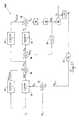
- FIG. 13Diagrammed in FIG. 13 is feedback system 109 which incorporates an algorithm 17 and comparator 12 .
- Observed velocity v OBSmay be sent to either comparator 12 or algorithm 14 . If observed velocity v OBS is sent to comparator 12 , then comparator 12 determines the velocity magnitude difference between the desired velocity v d and the observed velocity v OBS . Comparator 12 output velocity error ⁇ v is input to an algorithm 14 that converts ⁇ v to engine speed correction ⁇ c that is input to a second comparator 16 . If observed velocity v OBS is sent to algorithm 14 , in this embodiment algorithm 14 is modified to incorporate predetermined velocity v d and observed velocity v OBS in the calculation to determine engine speed correction ⁇ c .
Landscapes
- Engineering & Computer Science (AREA)
- Chemical & Material Sciences (AREA)
- Combustion & Propulsion (AREA)
- Radar, Positioning & Navigation (AREA)
- Remote Sensing (AREA)
- Mechanical Engineering (AREA)
- Automation & Control Theory (AREA)
- General Physics & Mathematics (AREA)
- Physics & Mathematics (AREA)
- Transportation (AREA)
- Ocean & Marine Engineering (AREA)
- Aviation & Aerospace Engineering (AREA)
- Combined Controls Of Internal Combustion Engines (AREA)
Abstract
Description
ωc=Kpεv+Kd(d/dt)εv+∫Klεvdt.
ωadapt(vd)=ωadapt(vd)+kadapt[ωadapt(vd)]Δtupdate
where kadaptand Δtupdateare factory-set parameters that together represent the speed at which the adaptive algorithms “learn” or develop a correlated data set. The last block on the
τadapt(ωd)=τadapt(ωd)+kadapt[τd−τadapt(ωd)]Δtupdate.
This is the same updating equation that is used in
ωadapt=ωm+[(vd−vm)/(vm+1−vm)](ωm+1−ωm).
Although
- Compute a weighting factor x using the following equation:
x=[(vd−vm)/(vm+1−vm)] - Note that x is always a value between 0 and 1.
Similar toalgorithm 18, update the two bracketing values ωm, ωm+1in the linear table using the following equations:
ωm=ωm+(1−x)kadapt[ωd−ωadapt]Δtupdate
ωm+1=ωm+1+(x)kadapt[ωd−ωadapt]Δtupdate
The other values in the linear table remain unchanged for this particular update, and are only updated when they bracket the operating condition of the engine at some other time. This same procedure can be used on the engine speed vs. torque adaptive table. It should be noted that ifalgorithm 18 is not present, then ωcwill equal ωadapt. Likewise ifalgorithm 22 is not present then τcwill equal τadapt.
- Compute a weighting factor x using the following equation:
| vd(kph) | ωadapt(rpm) | ||
| 0 | 0 | ||
| 10 | 1000 | ||
| 20 | 2000 | ||
| 30 | 3000 | ||
| 40 | 4000 | ||
| 50 | 5000 | ||
| 60 | 6000 | ||
The following is an example of the velocity vs. engine speed adaptive after the boat has been driven for a period of time:
| vd(kph) | ωadapt(rpm) | ||
| 0 | 0 | ||
| 10 | 1080 | ||
| 20 | 1810 | ||
| 30 | 2752 | ||
| 40 | 3810 | ||
| 50 | 5000 | ||
| 60 | 6000 | ||
Note that the engine speed values correlating to boat speeds of 50 and 60 kph have not been modified from the original initial values. This is because the boat was never operated at these desired speeds during the period of operation between the present table and the initial installation of the controller.
vAcc=∫aAccdt
The output from
vOBS=KP(vVMD−vAcc)KD(d/dt)(vVMD−vAcc)=∫Ki(vVMD−vAcc)
In this
ωc=Kpεv+Kdεa+∫Kiεvdt.
Where Kp, Kd, and Kiare, respectively, the appropriate proportional, derivative, and integral gains.
vOBS=KP(vVMD−vGPS)+KD(d/dt)(vVMD−vGPS)=∫Ki(vVMD−vGPS)
Claims (21)
Priority Applications (1)
| Application Number | Priority Date | Filing Date | Title |
|---|---|---|---|
| US12/965,556US9052717B1 (en) | 2004-02-11 | 2010-12-10 | Watercraft speed control device |
Applications Claiming Priority (10)
| Application Number | Priority Date | Filing Date | Title |
|---|---|---|---|
| US54361004P | 2004-02-11 | 2004-02-11 | |
| US11/056,848US7229330B2 (en) | 2004-02-11 | 2005-02-11 | Watercraft speed control device |
| US11/811,606US7485021B2 (en) | 2004-02-11 | 2007-06-11 | Watercraft speed control device |
| US11/811,605US7491104B2 (en) | 2004-02-11 | 2007-06-11 | Watercraft speed control device |
| US11/811,616US7494393B2 (en) | 2004-02-11 | 2007-06-11 | Watercraft speed control device |
| US11/811,604US7465203B2 (en) | 2004-02-11 | 2007-06-11 | Watercraft speed control device |
| US11/811,617US7494394B2 (en) | 2004-02-11 | 2007-06-11 | Watercraft speed control device |
| US11/903,208US20080243321A1 (en) | 2005-02-11 | 2007-09-19 | Event sensor |
| US12/391,101US7877174B2 (en) | 2005-02-11 | 2009-02-23 | Watercraft speed control device |
| US12/965,556US9052717B1 (en) | 2004-02-11 | 2010-12-10 | Watercraft speed control device |
Related Parent Applications (1)
| Application Number | Title | Priority Date | Filing Date |
|---|---|---|---|
| US11/056,848Continuation-In-PartUS7229330B2 (en) | 2004-02-11 | 2005-02-11 | Watercraft speed control device |
Publications (1)
| Publication Number | Publication Date |
|---|---|
| US9052717B1true US9052717B1 (en) | 2015-06-09 |
Family
ID=53267878
Family Applications (1)
| Application Number | Title | Priority Date | Filing Date |
|---|---|---|---|
| US12/965,556Expired - LifetimeUS9052717B1 (en) | 2004-02-11 | 2010-12-10 | Watercraft speed control device |
Country Status (1)
| Country | Link |
|---|---|
| US (1) | US9052717B1 (en) |
Cited By (14)
| Publication number | Priority date | Publication date | Assignee | Title |
|---|---|---|---|---|
| US20140379193A1 (en)* | 2011-12-30 | 2014-12-25 | General Electric Company | System, method, and computer program for an integrated human-machine interface (hmi) of an engine-generator |
| US9643698B1 (en) | 2014-12-17 | 2017-05-09 | Brunswick Corporation | Systems and methods for providing notification regarding trim angle of a marine propulsion device |
| US9694892B1 (en)* | 2015-12-29 | 2017-07-04 | Brunswick Corporation | System and method for trimming trimmable marine devices with respect to a marine vessel |
| US9745036B2 (en) | 2015-06-23 | 2017-08-29 | Brunswick Corporation | Systems and methods for automatically controlling attitude of a marine vessel with trim devices |
| US9751605B1 (en) | 2015-12-29 | 2017-09-05 | Brunswick Corporation | System and method for trimming a trimmable marine device with respect to a marine vessel |
| US9764810B1 (en) | 2015-06-23 | 2017-09-19 | Bruswick Corporation | Methods for positioning multiple trimmable marine propulsion devices on a marine vessel |
| US9896174B1 (en) | 2016-08-22 | 2018-02-20 | Brunswick Corporation | System and method for controlling trim position of propulsion device on a marine vessel |
| US9919781B1 (en) | 2015-06-23 | 2018-03-20 | Brunswick Corporation | Systems and methods for automatically controlling attitude of a marine vessel with trim devices |
| US10000267B1 (en) | 2017-08-14 | 2018-06-19 | Brunswick Corporation | Methods for trimming trimmable marine devices with respect to a marine vessel |
| US10011339B2 (en) | 2016-08-22 | 2018-07-03 | Brunswick Corporation | System and method for controlling trim position of propulsion devices on a marine vessel |
| US10118682B2 (en) | 2016-08-22 | 2018-11-06 | Brunswick Corporation | Method and system for controlling trim position of a propulsion device on a marine vessel |
| US10351221B1 (en) | 2017-09-01 | 2019-07-16 | Brunswick Corporation | Methods for automatically controlling attitude of a marine vessel during launch |
| US10518856B2 (en) | 2015-06-23 | 2019-12-31 | Brunswick Corporation | Systems and methods for automatically controlling attitude of a marine vessel with trim devices |
| US10829190B1 (en) | 2018-05-29 | 2020-11-10 | Brunswick Corporation | Trim control system and method |
Citations (96)
| Publication number | Priority date | Publication date | Assignee | Title |
|---|---|---|---|---|
| US3748466A (en) | 1971-06-14 | 1973-07-24 | Gen Signal Corp | Vehicle control system |
| US3921446A (en)* | 1971-04-07 | 1975-11-25 | Karl Ludloff | Method of measuring torque |
| US4392122A (en) | 1980-06-26 | 1983-07-05 | Hocken Redvers A | Magnetically triggered on-board elapsed time indicator |
| US4422423A (en) | 1979-04-24 | 1983-12-27 | Kabushiki Kaisha Toyota Chuo Kenyusho | Jet control type carburetor |
| US4939661A (en) | 1988-09-09 | 1990-07-03 | World Research Institute For Science And Technology | Apparatus for a video marine navigation plotter with electronic charting and methods for use therein |
| US5074810A (en) | 1990-06-29 | 1991-12-24 | Lakeland Engineering Corporation | Automatic speed control system for boats |
| US5110310A (en) | 1991-04-25 | 1992-05-05 | Lakeland Engineering Corporation | Automatic speed control system for boats |
| US5142473A (en) | 1988-08-12 | 1992-08-25 | Davis Dale R | Speed, acceleration, and trim control system for power boats |
| US5276660A (en) | 1992-05-29 | 1994-01-04 | Lee Richard D | Competition waterskier timing system |
| US5355855A (en) | 1993-12-27 | 1994-10-18 | Hitachi America, Ltd. | Integrated feed forward air/fuel ratio sensor for gaseous fuel engines |
| US5369589A (en) | 1993-09-15 | 1994-11-29 | Trimble Navigation Limited | Plural information display for navigation |
| US5367999A (en) | 1993-04-15 | 1994-11-29 | Mesa Environmental Ventures Limited Partnership | Method and system for improved fuel system performance of a gaseous fuel engine |
| US5404341A (en) | 1992-11-20 | 1995-04-04 | Seiko Instruments Inc. | Time measurement apparatus |
| US5458104A (en) | 1994-01-14 | 1995-10-17 | Walbro Corporation | Demand fuel pressure regulator |
| US5577474A (en)* | 1995-11-29 | 1996-11-26 | General Motors Corporation | Torque estimation for engine speed control |
| US5694337A (en) | 1995-04-03 | 1997-12-02 | Macken; John A. | Water ski performance analysis method and apparatus |
| US5700171A (en) | 1995-10-27 | 1997-12-23 | Perfect Pass Control Systems Incorporation | Speed control system |
| US5731788A (en) | 1995-01-11 | 1998-03-24 | Trimble Navigation | Global positioning and communications system and method for race and start line management |
| US5808671A (en) | 1994-11-24 | 1998-09-15 | Augat Photon Systems Inc. | Apparatus and method for remote monitoring of video signals |
| US5828979A (en) | 1994-09-01 | 1998-10-27 | Harris Corporation | Automatic train control system and method |
| US5828987A (en)* | 1995-08-28 | 1998-10-27 | Data Tec Co., Ltd. | Movement detecting device |
| US5848373A (en) | 1994-06-24 | 1998-12-08 | Delorme Publishing Company | Computer aided map location system |
| JPH1153700A (en) | 1997-07-30 | 1999-02-26 | Mitsubishi Electric Corp | Automatic ship steering system |
| US5884213A (en) | 1996-03-22 | 1999-03-16 | Johnson Worldwide Asociates, Inc. | System for controlling navigation of a fishing boat |
| US5904131A (en) | 1995-12-28 | 1999-05-18 | Cummins Engine Company, Inc. | Internal combustion engine with air/fuel ratio control |
| US5905713A (en) | 1996-04-15 | 1999-05-18 | Hughes Electronics Corporation | Method and apparatus for analyzing digital multi-program transmission packet streams |
| US5928040A (en)* | 1997-11-14 | 1999-07-27 | Wharton; Mark E. | Apparatus for determining apparent slip of marine motor vessel propellers, and method for doing same |
| US6035252A (en)* | 1997-09-30 | 2000-03-07 | Ford Global Technologies, Inc. | Engine torque control |
| US6041762A (en) | 1996-08-16 | 2000-03-28 | Impco Technologies, Inc. | Control module for natural gas fuel supply for a vehicle |
| US6131552A (en) | 1998-08-14 | 2000-10-17 | Dana Corporation | Fuel control system for a gas-operated engine |
| US6157297A (en) | 1997-06-20 | 2000-12-05 | Yamaha Hatsudoki Kabushiki Kaisha | Display for vehicle navigational system |
| US6169495B1 (en) | 1997-10-23 | 2001-01-02 | Toyota Jidosha Kabushiki Kaisha | Vehicle traffic control system |
| US6176224B1 (en) | 1998-03-30 | 2001-01-23 | Caterpillar Inc. | Method of operating an internal combustion engine which uses a low energy gaseous fuel |
| WO2001029512A1 (en) | 1999-10-19 | 2001-04-26 | Jfdi Engineering Limited | Improvements in or relating to vehicle navigation |
| US6227918B1 (en) | 2000-01-05 | 2001-05-08 | Mark E. Wharton | System for determining apparent slip and angle of attack |
| US6259381B1 (en) | 1995-11-09 | 2001-07-10 | David A Small | Method of triggering an event |
| US6267105B1 (en) | 1998-06-12 | 2001-07-31 | Bruno Bertossi | Electronic pressure reducer for liquid petroleum gasses |
| US6273771B1 (en) | 2000-03-17 | 2001-08-14 | Brunswick Corporation | Control system for a marine vessel |
| US6283240B1 (en) | 1998-09-02 | 2001-09-04 | Rover Group Limited | Vehicle |
| US6289278B1 (en) | 1998-02-27 | 2001-09-11 | Hitachi, Ltd. | Vehicle position information displaying apparatus and method |
| US20010032236A1 (en) | 1999-12-09 | 2001-10-18 | Ching-Fang Lin | Portable multi-tracking method and system |
| US6312301B1 (en) | 2000-09-15 | 2001-11-06 | Lawrence R. Kennedy | Virtual slalom course |
| US20010055063A1 (en) | 2000-05-26 | 2001-12-27 | Honda Giken Kogyo Kabushiki Kaisha | Position detection apparatus, position detection method and position detection program |
| US6340005B1 (en) | 2000-04-18 | 2002-01-22 | Rem Technology, Inc. | Air-fuel control system |
| US20020022927A1 (en) | 1993-08-11 | 2002-02-21 | Lemelson Jerome H. | GPS vehicle collision avoidance warning and control system and method |
| US6353781B1 (en)* | 2000-07-05 | 2002-03-05 | Nordskog Publishing, Inc. | GPS controlled marine speedometer unit with multiple operational modes |
| US6401446B1 (en) | 2000-06-23 | 2002-06-11 | Hamilton Sundstrand Corporation | Valve apparatus for providing shutoff and overspeed protection in a gas turbine fuel system |
| US6456910B1 (en) | 2000-11-21 | 2002-09-24 | John Andrew Roe | Light Guided autopilot |
| US6485341B1 (en)* | 2001-04-06 | 2002-11-26 | Brunswick Corporation | Method for controlling the average speed of a vehicle |
| US6507785B1 (en) | 2001-09-21 | 2003-01-14 | General Motors Corportion | Method and system for detecting and correcting off route navigation for server based route guidance systems |
| US6517396B1 (en) | 2000-07-03 | 2003-02-11 | Stephen W. Into | Boat speed control |
| US20030036814A1 (en) | 2001-08-14 | 2003-02-20 | Middleton Paul Lawrence | Slalom water-ski training and monitoring system for on-water use |
| US20030060973A1 (en) | 2001-05-31 | 2003-03-27 | Infomove, Inc. | Method and system for distributed navigation and automated guidance |
| US6573486B1 (en) | 2002-02-22 | 2003-06-03 | Northrop Grumman Corporation | Projectile guidance with accelerometers and a GPS receiver |
| US6577932B1 (en) | 1998-09-16 | 2003-06-10 | Wärtsilä Propulsion Netherlands B.V. | System for controlling a vessel |
| US6701905B1 (en) | 2003-04-30 | 2004-03-09 | Delphi Technologies, Inc. | Fuel pressure control method for an alternate-fuel engine |
| US20040056779A1 (en) | 2002-07-01 | 2004-03-25 | Rast Rodger H. | Transportation signaling device |
| US6722302B2 (en) | 2000-09-18 | 2004-04-20 | Kawasaki Jukogyo Kabushiki Kaisha | Jet-propulsion watercraft |
| US6763226B1 (en) | 2002-07-31 | 2004-07-13 | Computer Science Central, Inc. | Multifunctional world wide walkie talkie, a tri-frequency cellular-satellite wireless instant messenger computer and network for establishing global wireless volp quality of service (qos) communications, unified messaging, and video conferencing via the internet |
| US20040150557A1 (en) | 2003-01-21 | 2004-08-05 | Ford Thomas John | Inertial GPS navigation system with modified kalman filter |
| US6779752B1 (en) | 2003-03-25 | 2004-08-24 | Northrop Grumman Corporation | Projectile guidance with accelerometers and a GPS receiver |
| US6826478B2 (en) | 2002-04-12 | 2004-11-30 | Ensco, Inc. | Inertial navigation system for mobile objects with constraints |
| US6845321B1 (en) | 2003-06-30 | 2005-01-18 | Michael Lester Kerns | Method and system for providing narrative information to a traveler |
| US6855020B2 (en)* | 2000-10-30 | 2005-02-15 | Yamaha Hatsudoki Kabushiki Kaisha | Running control device for watercraft |
| US6864807B2 (en) | 2001-07-09 | 2005-03-08 | Nissan Motor Co., Ltd. | Information display system for vehicle |
| US6884128B2 (en)* | 2002-10-23 | 2005-04-26 | Yamaha Marine Kabushiki Kaisha | Speed control system and method for watercraft |
| US20050176312A1 (en) | 2004-02-11 | 2005-08-11 | Econtrols, Inc. | Watercraft speed control device |
| US20050191916A1 (en) | 2004-03-01 | 2005-09-01 | Mark Bozicevic | System and device for improving the performance of a water skier in a slalom course |
| US20050222933A1 (en) | 2002-05-21 | 2005-10-06 | Wesby Philip B | System and method for monitoring and control of wireless modules linked to assets |
| US6959240B2 (en) | 2002-04-15 | 2005-10-25 | Pioneer Corporation | Correction device for correcting acceleration data, method therefor, program therefor, recording medium containing the program and navigation guide device |
| US6997763B2 (en)* | 2001-10-19 | 2006-02-14 | Yamaha Hatsudoki Kabushiki Kaisha | Running control device |
| US20060038718A1 (en) | 2004-01-11 | 2006-02-23 | Tokimec, Inc. | Azimuth/attitude detecting sensor |
| US20060074540A1 (en) | 2004-10-05 | 2006-04-06 | Vision Works, Llc | Absolute acceleration sensor for use within moving vehicles |
| US7031224B2 (en) | 2004-01-26 | 2006-04-18 | Michael H. Reifer | Buoy-to-sailboat distance indicator system |
| US20060089794A1 (en) | 2004-10-22 | 2006-04-27 | Depasqua Louis | Touch display fishing boat steering system and method |
| US20060176216A1 (en) | 2004-11-17 | 2006-08-10 | Hipskind Jason C | Tracking and timing system |
| US7143363B1 (en) | 2002-07-25 | 2006-11-28 | Brunswick Corporation | Method for displaying marine vessel information for an operator |
| US7150430B2 (en) | 2000-03-10 | 2006-12-19 | Silansky Edward R | Internet linked environmental data collection system and method |
| US7214110B1 (en) | 2005-10-06 | 2007-05-08 | Brunswick Corporation | Acceleration control system for a marine vessel |
| US20080003899A1 (en) | 2004-02-11 | 2008-01-03 | Econtrols, Inc. | Watercraft speed control device |
| US20080009206A1 (en) | 2004-02-11 | 2008-01-10 | Econtrols, Inc. | Watercraft speed control device |
| US20080009205A1 (en) | 2004-02-11 | 2008-01-10 | Econtrols, Inc. | Watercraft speed control device |
| US20080085642A1 (en) | 2006-10-04 | 2008-04-10 | Econtrols, Inc. | Method for engaging a watercraft speed control system |
| US7361067B1 (en)* | 2006-11-02 | 2008-04-22 | Brunswick Corporation | Method for controlling the acceleration of a marine vessel used for water skiing |
| US20080133131A1 (en) | 2006-11-30 | 2008-06-05 | Raytheon Company | Route-planning interactive navigation system and method |
| US7494394B2 (en) | 2004-02-11 | 2009-02-24 | Econtrols, Inc. | Watercraft speed control device |
| US7494393B2 (en) | 2004-02-11 | 2009-02-24 | Econtrols, Inc. | Watercraft speed control device |
| US20090209153A1 (en)* | 2004-02-11 | 2009-08-20 | Econtrols, Inc. | Watercraft speed control device |
| US20100087110A1 (en) | 2008-10-03 | 2010-04-08 | Berg Christopher P J | Automatic Deploying and Positioning Slalom Water Ski Course |
| US7841440B2 (en) | 2007-08-07 | 2010-11-30 | Southern Taiwan University | Fuel safety control apparatus for vehicle |
| US7877174B2 (en) | 2005-02-11 | 2011-01-25 | Econtrols, Inc. | Watercraft speed control device |
| US7883383B2 (en) | 2006-02-01 | 2011-02-08 | Cpac Systems Ab | Method and arrangement for controlling a drive arrangement in a watercraft |
| US7934983B1 (en) | 2009-11-24 | 2011-05-03 | Seth Eisner | Location-aware distributed sporting events |
| US8006668B1 (en) | 2006-06-29 | 2011-08-30 | Econtrols, Inc. | Electronic pressure regulator |
| US8136506B1 (en) | 2006-06-29 | 2012-03-20 | Econtrols, Inc. | Electronic pressure regulator |
| US8176897B1 (en) | 2006-06-29 | 2012-05-15 | E-Controls, Inc. | Electronic pressure regulator |
- 2010
- 2010-12-10USUS12/965,556patent/US9052717B1/ennot_activeExpired - Lifetime
Patent Citations (104)
| Publication number | Priority date | Publication date | Assignee | Title |
|---|---|---|---|---|
| US3921446A (en)* | 1971-04-07 | 1975-11-25 | Karl Ludloff | Method of measuring torque |
| US3748466A (en) | 1971-06-14 | 1973-07-24 | Gen Signal Corp | Vehicle control system |
| US4422423A (en) | 1979-04-24 | 1983-12-27 | Kabushiki Kaisha Toyota Chuo Kenyusho | Jet control type carburetor |
| US4392122A (en) | 1980-06-26 | 1983-07-05 | Hocken Redvers A | Magnetically triggered on-board elapsed time indicator |
| US5142473A (en) | 1988-08-12 | 1992-08-25 | Davis Dale R | Speed, acceleration, and trim control system for power boats |
| US4939661A (en) | 1988-09-09 | 1990-07-03 | World Research Institute For Science And Technology | Apparatus for a video marine navigation plotter with electronic charting and methods for use therein |
| US5074810A (en) | 1990-06-29 | 1991-12-24 | Lakeland Engineering Corporation | Automatic speed control system for boats |
| US5110310A (en) | 1991-04-25 | 1992-05-05 | Lakeland Engineering Corporation | Automatic speed control system for boats |
| US5276660A (en) | 1992-05-29 | 1994-01-04 | Lee Richard D | Competition waterskier timing system |
| US5404341A (en) | 1992-11-20 | 1995-04-04 | Seiko Instruments Inc. | Time measurement apparatus |
| US5367999A (en) | 1993-04-15 | 1994-11-29 | Mesa Environmental Ventures Limited Partnership | Method and system for improved fuel system performance of a gaseous fuel engine |
| US20020022927A1 (en) | 1993-08-11 | 2002-02-21 | Lemelson Jerome H. | GPS vehicle collision avoidance warning and control system and method |
| US5369589A (en) | 1993-09-15 | 1994-11-29 | Trimble Navigation Limited | Plural information display for navigation |
| US5355855A (en) | 1993-12-27 | 1994-10-18 | Hitachi America, Ltd. | Integrated feed forward air/fuel ratio sensor for gaseous fuel engines |
| US5458104A (en) | 1994-01-14 | 1995-10-17 | Walbro Corporation | Demand fuel pressure regulator |
| US5848373A (en) | 1994-06-24 | 1998-12-08 | Delorme Publishing Company | Computer aided map location system |
| US5828979A (en) | 1994-09-01 | 1998-10-27 | Harris Corporation | Automatic train control system and method |
| US5808671A (en) | 1994-11-24 | 1998-09-15 | Augat Photon Systems Inc. | Apparatus and method for remote monitoring of video signals |
| US5731788A (en) | 1995-01-11 | 1998-03-24 | Trimble Navigation | Global positioning and communications system and method for race and start line management |
| US5694337A (en) | 1995-04-03 | 1997-12-02 | Macken; John A. | Water ski performance analysis method and apparatus |
| US5828987A (en)* | 1995-08-28 | 1998-10-27 | Data Tec Co., Ltd. | Movement detecting device |
| US5700171A (en) | 1995-10-27 | 1997-12-23 | Perfect Pass Control Systems Incorporation | Speed control system |
| US6259381B1 (en) | 1995-11-09 | 2001-07-10 | David A Small | Method of triggering an event |
| US5577474A (en)* | 1995-11-29 | 1996-11-26 | General Motors Corporation | Torque estimation for engine speed control |
| US6041765A (en) | 1995-12-28 | 2000-03-28 | Cummins Engine Company, Inc. | Internal combustion engine with air/fuel ratio control |
| US5904131A (en) | 1995-12-28 | 1999-05-18 | Cummins Engine Company, Inc. | Internal combustion engine with air/fuel ratio control |
| US5884213A (en) | 1996-03-22 | 1999-03-16 | Johnson Worldwide Asociates, Inc. | System for controlling navigation of a fishing boat |
| US5905713A (en) | 1996-04-15 | 1999-05-18 | Hughes Electronics Corporation | Method and apparatus for analyzing digital multi-program transmission packet streams |
| US6041762A (en) | 1996-08-16 | 2000-03-28 | Impco Technologies, Inc. | Control module for natural gas fuel supply for a vehicle |
| US6157297A (en) | 1997-06-20 | 2000-12-05 | Yamaha Hatsudoki Kabushiki Kaisha | Display for vehicle navigational system |
| JPH1153700A (en) | 1997-07-30 | 1999-02-26 | Mitsubishi Electric Corp | Automatic ship steering system |
| US6035252A (en)* | 1997-09-30 | 2000-03-07 | Ford Global Technologies, Inc. | Engine torque control |
| US6169495B1 (en) | 1997-10-23 | 2001-01-02 | Toyota Jidosha Kabushiki Kaisha | Vehicle traffic control system |
| US5928040A (en)* | 1997-11-14 | 1999-07-27 | Wharton; Mark E. | Apparatus for determining apparent slip of marine motor vessel propellers, and method for doing same |
| US6289278B1 (en) | 1998-02-27 | 2001-09-11 | Hitachi, Ltd. | Vehicle position information displaying apparatus and method |
| US6176224B1 (en) | 1998-03-30 | 2001-01-23 | Caterpillar Inc. | Method of operating an internal combustion engine which uses a low energy gaseous fuel |
| US6267105B1 (en) | 1998-06-12 | 2001-07-31 | Bruno Bertossi | Electronic pressure reducer for liquid petroleum gasses |
| US6131552A (en) | 1998-08-14 | 2000-10-17 | Dana Corporation | Fuel control system for a gas-operated engine |
| US6283240B1 (en) | 1998-09-02 | 2001-09-04 | Rover Group Limited | Vehicle |
| US6577932B1 (en) | 1998-09-16 | 2003-06-10 | Wärtsilä Propulsion Netherlands B.V. | System for controlling a vessel |
| WO2001029512A1 (en) | 1999-10-19 | 2001-04-26 | Jfdi Engineering Limited | Improvements in or relating to vehicle navigation |
| US20010032236A1 (en) | 1999-12-09 | 2001-10-18 | Ching-Fang Lin | Portable multi-tracking method and system |
| US6227918B1 (en) | 2000-01-05 | 2001-05-08 | Mark E. Wharton | System for determining apparent slip and angle of attack |
| US7150430B2 (en) | 2000-03-10 | 2006-12-19 | Silansky Edward R | Internet linked environmental data collection system and method |
| US6273771B1 (en) | 2000-03-17 | 2001-08-14 | Brunswick Corporation | Control system for a marine vessel |
| US6340005B1 (en) | 2000-04-18 | 2002-01-22 | Rem Technology, Inc. | Air-fuel control system |
| US20010055063A1 (en) | 2000-05-26 | 2001-12-27 | Honda Giken Kogyo Kabushiki Kaisha | Position detection apparatus, position detection method and position detection program |
| US6401446B1 (en) | 2000-06-23 | 2002-06-11 | Hamilton Sundstrand Corporation | Valve apparatus for providing shutoff and overspeed protection in a gas turbine fuel system |
| US6517396B1 (en) | 2000-07-03 | 2003-02-11 | Stephen W. Into | Boat speed control |
| US6353781B1 (en)* | 2000-07-05 | 2002-03-05 | Nordskog Publishing, Inc. | GPS controlled marine speedometer unit with multiple operational modes |
| US6312301B1 (en) | 2000-09-15 | 2001-11-06 | Lawrence R. Kennedy | Virtual slalom course |
| US6722302B2 (en) | 2000-09-18 | 2004-04-20 | Kawasaki Jukogyo Kabushiki Kaisha | Jet-propulsion watercraft |
| US6855020B2 (en)* | 2000-10-30 | 2005-02-15 | Yamaha Hatsudoki Kabushiki Kaisha | Running control device for watercraft |
| US6456910B1 (en) | 2000-11-21 | 2002-09-24 | John Andrew Roe | Light Guided autopilot |
| US6485341B1 (en)* | 2001-04-06 | 2002-11-26 | Brunswick Corporation | Method for controlling the average speed of a vehicle |
| US20030060973A1 (en) | 2001-05-31 | 2003-03-27 | Infomove, Inc. | Method and system for distributed navigation and automated guidance |
| US6864807B2 (en) | 2001-07-09 | 2005-03-08 | Nissan Motor Co., Ltd. | Information display system for vehicle |
| US20030036814A1 (en) | 2001-08-14 | 2003-02-20 | Middleton Paul Lawrence | Slalom water-ski training and monitoring system for on-water use |
| US6507785B1 (en) | 2001-09-21 | 2003-01-14 | General Motors Corportion | Method and system for detecting and correcting off route navigation for server based route guidance systems |
| US6997763B2 (en)* | 2001-10-19 | 2006-02-14 | Yamaha Hatsudoki Kabushiki Kaisha | Running control device |
| US6573486B1 (en) | 2002-02-22 | 2003-06-03 | Northrop Grumman Corporation | Projectile guidance with accelerometers and a GPS receiver |
| US6826478B2 (en) | 2002-04-12 | 2004-11-30 | Ensco, Inc. | Inertial navigation system for mobile objects with constraints |
| US6959240B2 (en) | 2002-04-15 | 2005-10-25 | Pioneer Corporation | Correction device for correcting acceleration data, method therefor, program therefor, recording medium containing the program and navigation guide device |
| US20050222933A1 (en) | 2002-05-21 | 2005-10-06 | Wesby Philip B | System and method for monitoring and control of wireless modules linked to assets |
| US7027808B2 (en) | 2002-05-21 | 2006-04-11 | Philip Bernard Wesby | System and method for monitoring and control of wireless modules linked to assets |
| US20040056779A1 (en) | 2002-07-01 | 2004-03-25 | Rast Rodger H. | Transportation signaling device |
| US7143363B1 (en) | 2002-07-25 | 2006-11-28 | Brunswick Corporation | Method for displaying marine vessel information for an operator |
| US6763226B1 (en) | 2002-07-31 | 2004-07-13 | Computer Science Central, Inc. | Multifunctional world wide walkie talkie, a tri-frequency cellular-satellite wireless instant messenger computer and network for establishing global wireless volp quality of service (qos) communications, unified messaging, and video conferencing via the internet |
| US6884128B2 (en)* | 2002-10-23 | 2005-04-26 | Yamaha Marine Kabushiki Kaisha | Speed control system and method for watercraft |
| US20040150557A1 (en) | 2003-01-21 | 2004-08-05 | Ford Thomas John | Inertial GPS navigation system with modified kalman filter |
| US6779752B1 (en) | 2003-03-25 | 2004-08-24 | Northrop Grumman Corporation | Projectile guidance with accelerometers and a GPS receiver |
| US6701905B1 (en) | 2003-04-30 | 2004-03-09 | Delphi Technologies, Inc. | Fuel pressure control method for an alternate-fuel engine |
| US6845321B1 (en) | 2003-06-30 | 2005-01-18 | Michael Lester Kerns | Method and system for providing narrative information to a traveler |
| US20060038718A1 (en) | 2004-01-11 | 2006-02-23 | Tokimec, Inc. | Azimuth/attitude detecting sensor |
| US7031224B2 (en) | 2004-01-26 | 2006-04-18 | Michael H. Reifer | Buoy-to-sailboat distance indicator system |
| US7465203B2 (en) | 2004-02-11 | 2008-12-16 | Econtrols, Inc. | Watercraft speed control device |
| US20090209153A1 (en)* | 2004-02-11 | 2009-08-20 | Econtrols, Inc. | Watercraft speed control device |
| US7494393B2 (en) | 2004-02-11 | 2009-02-24 | Econtrols, Inc. | Watercraft speed control device |
| US20050176312A1 (en) | 2004-02-11 | 2005-08-11 | Econtrols, Inc. | Watercraft speed control device |
| US8145372B2 (en) | 2004-02-11 | 2012-03-27 | Econtrols, Inc. | Watercraft speed control device |
| US7494394B2 (en) | 2004-02-11 | 2009-02-24 | Econtrols, Inc. | Watercraft speed control device |
| US7229330B2 (en) | 2004-02-11 | 2007-06-12 | Econtrols, Inc. | Watercraft speed control device |
| US20080003899A1 (en) | 2004-02-11 | 2008-01-03 | Econtrols, Inc. | Watercraft speed control device |
| US20080009206A1 (en) | 2004-02-11 | 2008-01-10 | Econtrols, Inc. | Watercraft speed control device |
| US20080009205A1 (en) | 2004-02-11 | 2008-01-10 | Econtrols, Inc. | Watercraft speed control device |
| US7491104B2 (en) | 2004-02-11 | 2009-02-17 | Econtrols, Inc. | Watercraft speed control device |
| US7485021B2 (en) | 2004-02-11 | 2009-02-03 | Econtrols, Inc. | Watercraft speed control device |
| US20050191916A1 (en) | 2004-03-01 | 2005-09-01 | Mark Bozicevic | System and device for improving the performance of a water skier in a slalom course |
| US7344377B2 (en) | 2004-03-01 | 2008-03-18 | Mark Bozicevic | System and device for improving the performance of a water skier in a slalom course |
| US20060074540A1 (en) | 2004-10-05 | 2006-04-06 | Vision Works, Llc | Absolute acceleration sensor for use within moving vehicles |
| US20060089794A1 (en) | 2004-10-22 | 2006-04-27 | Depasqua Louis | Touch display fishing boat steering system and method |
| US20060176216A1 (en) | 2004-11-17 | 2006-08-10 | Hipskind Jason C | Tracking and timing system |
| US7877174B2 (en) | 2005-02-11 | 2011-01-25 | Econtrols, Inc. | Watercraft speed control device |
| US7214110B1 (en) | 2005-10-06 | 2007-05-08 | Brunswick Corporation | Acceleration control system for a marine vessel |
| US7883383B2 (en) | 2006-02-01 | 2011-02-08 | Cpac Systems Ab | Method and arrangement for controlling a drive arrangement in a watercraft |
| US8006668B1 (en) | 2006-06-29 | 2011-08-30 | Econtrols, Inc. | Electronic pressure regulator |
| US8136506B1 (en) | 2006-06-29 | 2012-03-20 | Econtrols, Inc. | Electronic pressure regulator |
| US8176897B1 (en) | 2006-06-29 | 2012-05-15 | E-Controls, Inc. | Electronic pressure regulator |
| US20080085642A1 (en) | 2006-10-04 | 2008-04-10 | Econtrols, Inc. | Method for engaging a watercraft speed control system |
| US7361067B1 (en)* | 2006-11-02 | 2008-04-22 | Brunswick Corporation | Method for controlling the acceleration of a marine vessel used for water skiing |
| US20080133131A1 (en) | 2006-11-30 | 2008-06-05 | Raytheon Company | Route-planning interactive navigation system and method |
| US7841440B2 (en) | 2007-08-07 | 2010-11-30 | Southern Taiwan University | Fuel safety control apparatus for vehicle |
| US20100087110A1 (en) | 2008-10-03 | 2010-04-08 | Berg Christopher P J | Automatic Deploying and Positioning Slalom Water Ski Course |
| US7934983B1 (en) | 2009-11-24 | 2011-05-03 | Seth Eisner | Location-aware distributed sporting events |
Non-Patent Citations (17)
| Title |
|---|
| "Cruise and Tow with Consistent Control," Mercury SmartCraft DTS SmartTow brochure, copyright 2006, Mercury Marine. (2 pages). |
| "Mercury Marine Launches Smart Tow Pro for DTS SmartCraft Engines." Mercury News Release, Dec. 18, 2007 (2 pages). |
| "Power Trip. Hit it with Mercury's New Smart Two Speed Control," Doc Talk brochure (1 page). |
| "Smart Tow Pro-The Next Wave in Tow Sport Technology," Mercury SmartCraft DTS Smart Tow Pro (GPS Precision) brochure, copyright 2009, Mercury Marine. (2 pages). |
| "Understanding Smart Tow Profiles," Mercury SmartCraft DTS (2 pages). |
| Aesthetic value characterization of landscapes in coastal zones; Depellegrin, D.; Blazauskas, N.; Vigl, L.E; Baltic International Symposium (BALTIC), 2012 IEEE/OES; DOI: 10.1109/BALTIC.2012.6249166; Publication Year: 2012, pp. 1-6. |
| http://www.mercurymarine.com/otherproducts/smartcraft/smartcraftinaction/smarttow.php. (2 pages). |
| Locating Subsurface Targets Using Minimal GPR Measurements; Gurbuz, A.C.; McClellan, J.H.; Scott, W.R.; Signal Processing and Communications Applications, 2006 IEEE 14th; DOI: 10.1109/SIU.2006.1659746; Publication Year: 2006; pp. 1-4. |
| Matching of ground-based LiDAR and aerial image data for mobile robot localization in densely forested environments; Hussein, M.; Renner, M.; Watanabe, M.; Iagnemma, K.; Intelligent Robots and Systems (IROS), 2013 IEEE/RSJ International Conference on DOI: 10.1109/IROS.2013.6696537; Publication Year: 2013 , pp. 1432-1437. |
| Mercury SmartCraft Operations Manual; This Manual Describes the SmartCraft Tachometer/Speedometer Gauge Systems; Copyright Mercury Marine, 90-898283015-907 (copyright 2007) (88 pages). |
| Modified Hopfield Neural Network Algorithm (MHNNA) for TSS mapping in Penang strait, Malaysia; Kzar, A.A.; MatJafri, M.Z.; Lim, H.S.; Mutter, K.N.; Syahreza, S.; Signal and Image Processing Applications (ICSIPA), 2013 IEEE International Conference on DOI: 10.1109/ICSIPA.2013.6708001; Publication Year: 2013; pp. 187-192. |
| Multi-UAV-based stereo vision system without GPS for ground obstacle mapping to assist path planning of UGV; Jin Hyo Kim; Ji-Wook Kwon; Jiwon Seo; Electronics Letters; vol. 50, Issue: 20; DOI: 10.1049/el.2014.2227; Publication Year: 2014; pp. 1431-1432. |
| Pattern of life for radar port and river security; Silvious, J.; Tahmoush, D.; Homeland Security (HST), 2012 IEEE Conference on Technologies for; DOI: 10.1109/THS.2012.6459921; Publication Year: 2012; pp. 626-630. |
| Queue detection using computer image processing; Hoose, N; Road Traffic Monitoring, 1989., Second International Conference on Publication Year: 1989, pp. 94-98. |
| Race Technology Speedbox 200Hz non-contact speed sensor brochure; Race Technology, Ltd., Strelley Hall, Main Street, Nottingham, England NG8 6PE (6 pages). |
| Race Technology Speedbox 200Hz non-contact speed sensor brochure; Race Technology, Ltd., Strelley Hall, Main Street, Strelley, Nottingham, England NG8 6PE. |
| Ship positioning by matching radar images and map data; Aytac, A.E.; Aksoy, 0.; Akgul, Y.S.; Signal Processing and Communications Applications Conference (SIU), 2014 22nd; DOI: 10.1109/SIU.2014.6830506; Publication Year: 2014; pp. 1423-1426. |
Cited By (19)
| Publication number | Priority date | Publication date | Assignee | Title |
|---|---|---|---|---|
| US9630510B2 (en)* | 2011-12-30 | 2017-04-25 | General Electric Company | System, method, and computer program for an integrated human-machine interface (HMI) of an engine-generator |
| US20140379193A1 (en)* | 2011-12-30 | 2014-12-25 | General Electric Company | System, method, and computer program for an integrated human-machine interface (hmi) of an engine-generator |
| US9643698B1 (en) | 2014-12-17 | 2017-05-09 | Brunswick Corporation | Systems and methods for providing notification regarding trim angle of a marine propulsion device |
| US10118681B1 (en) | 2015-06-23 | 2018-11-06 | Brunswick Corporation | System and method for automatically controlling trim position of a marine drive unit |
| US9745036B2 (en) | 2015-06-23 | 2017-08-29 | Brunswick Corporation | Systems and methods for automatically controlling attitude of a marine vessel with trim devices |
| US9764810B1 (en) | 2015-06-23 | 2017-09-19 | Bruswick Corporation | Methods for positioning multiple trimmable marine propulsion devices on a marine vessel |
| US9862471B1 (en) | 2015-06-23 | 2018-01-09 | Brunswick Corporation | Systems and methods for positioning multiple trimmable marine propulsion devices on a marine vessel |
| US9919781B1 (en) | 2015-06-23 | 2018-03-20 | Brunswick Corporation | Systems and methods for automatically controlling attitude of a marine vessel with trim devices |
| US10518856B2 (en) | 2015-06-23 | 2019-12-31 | Brunswick Corporation | Systems and methods for automatically controlling attitude of a marine vessel with trim devices |
| US10137971B2 (en) | 2015-06-23 | 2018-11-27 | Brunswick Corporation | Systems and methods for automatically controlling attitude of a marine vessel with trim devices |
| US9694892B1 (en)* | 2015-12-29 | 2017-07-04 | Brunswick Corporation | System and method for trimming trimmable marine devices with respect to a marine vessel |
| US9751605B1 (en) | 2015-12-29 | 2017-09-05 | Brunswick Corporation | System and method for trimming a trimmable marine device with respect to a marine vessel |
| US9896174B1 (en) | 2016-08-22 | 2018-02-20 | Brunswick Corporation | System and method for controlling trim position of propulsion device on a marine vessel |
| US10112692B1 (en) | 2016-08-22 | 2018-10-30 | Brunswick Corporation | System and method for controlling trim position of propulsion device on a marine vessel |
| US10118682B2 (en) | 2016-08-22 | 2018-11-06 | Brunswick Corporation | Method and system for controlling trim position of a propulsion device on a marine vessel |
| US10011339B2 (en) | 2016-08-22 | 2018-07-03 | Brunswick Corporation | System and method for controlling trim position of propulsion devices on a marine vessel |
| US10000267B1 (en) | 2017-08-14 | 2018-06-19 | Brunswick Corporation | Methods for trimming trimmable marine devices with respect to a marine vessel |
| US10351221B1 (en) | 2017-09-01 | 2019-07-16 | Brunswick Corporation | Methods for automatically controlling attitude of a marine vessel during launch |
| US10829190B1 (en) | 2018-05-29 | 2020-11-10 | Brunswick Corporation | Trim control system and method |
Similar Documents
| Publication | Publication Date | Title |
|---|---|---|
| US7877174B2 (en) | Watercraft speed control device | |
| US9052717B1 (en) | Watercraft speed control device | |
| US7494394B2 (en) | Watercraft speed control device | |
| US7494393B2 (en) | Watercraft speed control device | |
| US7465203B2 (en) | Watercraft speed control device | |
| US7485021B2 (en) | Watercraft speed control device | |
| US7491104B2 (en) | Watercraft speed control device | |
| US7229330B2 (en) | Watercraft speed control device | |
| US8145372B2 (en) | Watercraft speed control device | |
| US7818108B2 (en) | System of automatic control of maneuver of motor crafts, related method, and craft provided with the system | |
| US6485341B1 (en) | Method for controlling the average speed of a vehicle | |
| EP2386478B1 (en) | Control of a waterjet propelled vessel | |
| US7890225B2 (en) | Automatic pilot module and system for automatically steering a sailboat for sailing in the presence of waves | |
| JP7622274B2 (en) | Fuel efficiency calculation device and ship | |
| US8521348B1 (en) | Watercraft speed control device | |
| US8475221B1 (en) | Watercraft speed control device | |
| JP7448414B2 (en) | Rudder control device and ship | |
| DK157071B (en) | PROCEDURE FOR REGULATING THE PROGRAMMING MACHINERY IN A VESSEL WITH STYLE PROPELLER | |
| KR20210096567A (en) | Fuel control apparatus and rudder control apparatus | |
| JPS6218399B2 (en) |
Legal Events
| Date | Code | Title | Description |
|---|---|---|---|
| AS | Assignment | Owner name:ECONTROLS, LLC, TEXAS Free format text:ASSIGNMENT OF ASSIGNORS INTEREST;ASSIGNOR:ECONTROLS GROUP, INC.;REEL/FRAME:033767/0920 Effective date:20090930 Owner name:ENOVATION CONTROLS, LLC, OKLAHOMA Free format text:ASSIGNMENT OF ASSIGNORS INTEREST;ASSIGNOR:ECONTROLS, LLC;REEL/FRAME:033768/0003 Effective date:20130101 Owner name:ECONTROLS, INC., TEXAS Free format text:ASSIGNMENT OF ASSIGNORS INTEREST;ASSIGNOR:ECONTROLS GROUP, INC.;REEL/FRAME:033767/0386 Effective date:20090930 Owner name:ECONTROLS GROUP, INC., TEXAS Free format text:ASSIGNMENT OF ASSIGNORS INTEREST;ASSIGNOR:ECONTROLS, INC.;REEL/FRAME:033767/0415 Effective date:20090910 Owner name:ECONTROLS, LLC, TEXAS Free format text:ASSIGNMENT OF ASSIGNORS INTEREST;ASSIGNOR:ECONTROLS, INC.;REEL/FRAME:033766/0327 Effective date:20090930 | |
| AS | Assignment | Owner name:BOKF, NA DBA BANK OF OKLAHOMA, AS ADMIN. AGENT, OK Free format text:SECURITY AGREEMENT;ASSIGNOR:ENOVATION CONTROLS, LLC;REEL/FRAME:034013/0158 Effective date:20140630 | |
| STCF | Information on status: patent grant | Free format text:PATENTED CASE | |
| AS | Assignment | Owner name:ENOVATION CONTROLS, LLC, OKLAHOMA Free format text:RELEASE;ASSIGNOR:BOKF, NA DBA BANK OF OKLAHOMA, AS ADMINISTRATIVE AGENT;REEL/FRAME:040821/0431 Effective date:20161205 | |
| AS | Assignment | Owner name:PNC BANK, NATIONAL ASSOCIATION, PENNSYLVANIA Free format text:ACKNOWLEDGMENT OF SECURITY INTEREST IN INTELLECTUAL PROPERTY;ASSIGNORS:SUN HYDRAULICS CORPORATION;ENOVATION CONTROLS, LLC;SUN HYDRAULICS, LLC;REEL/FRAME:046468/0256 Effective date:20180403 | |
| MAFP | Maintenance fee payment | Free format text:PAYMENT OF MAINTENANCE FEE, 4TH YEAR, LARGE ENTITY (ORIGINAL EVENT CODE: M1551); ENTITY STATUS OF PATENT OWNER: LARGE ENTITY Year of fee payment:4 | |
| AS | Assignment | Owner name:PNC BANK, NATIONAL ASSOCIATION, AS ADMINISTRATIVE AGENT, PENNSYLVANIA Free format text:NOTICE OF GRANT OF SECURITY INTEREST IN PATENTS;ASSIGNOR:ENOVATION CONTROLS, LLC;REEL/FRAME:054242/0073 Effective date:20201028 | |
| AS | Assignment | Owner name:ENOVATION CONTROLS, LLC, OKLAHOMA Free format text:ASSIGNMENT OF ASSIGNORS INTEREST;ASSIGNORS:WALSER, MICHAEL W;GUGLIELMO, KENNON H;SHOUSE, KENNETH R;AND OTHERS;REEL/FRAME:054597/0197 Effective date:20070608 | |
| MAFP | Maintenance fee payment | Free format text:PAYMENT OF MAINTENANCE FEE, 8TH YEAR, LARGE ENTITY (ORIGINAL EVENT CODE: M1552); ENTITY STATUS OF PATENT OWNER: LARGE ENTITY Year of fee payment:8 |