US9052403B2 - Compact mobile cargo scanning system - Google Patents
Compact mobile cargo scanning systemDownload PDFInfo
- Publication number
- US9052403B2 US9052403B2US14/104,637US201314104637AUS9052403B2US 9052403 B2US9052403 B2US 9052403B2US 201314104637 AUS201314104637 AUS 201314104637AUS 9052403 B2US9052403 B2US 9052403B2
- Authority
- US
- United States
- Prior art keywords
- boom
- vehicle
- inspection system
- ray
- source
- Prior art date
- Legal status (The legal status is an assumption and is not a legal conclusion. Google has not performed a legal analysis and makes no representation as to the accuracy of the status listed.)
- Expired - Fee Related
Links
- 238000007689inspectionMethods0.000claimsabstractdescription135
- 230000033001locomotionEffects0.000claimsdescription24
- 230000035515penetrationEffects0.000claimsdescription19
- 229910000831SteelInorganic materials0.000claimsdescription14
- 239000010959steelSubstances0.000claimsdescription14
- 238000004891communicationMethods0.000claimsdescription5
- 238000000034methodMethods0.000abstractdescription29
- 239000000463materialSubstances0.000abstractdescription23
- 230000005484gravityEffects0.000abstractdescription5
- 230000005855radiationEffects0.000description44
- 238000013461designMethods0.000description30
- 230000007246mechanismEffects0.000description24
- 238000003384imaging methodMethods0.000description11
- 230000007704transitionEffects0.000description10
- 230000007717exclusionEffects0.000description8
- 230000008901benefitEffects0.000description7
- 230000005251gamma rayEffects0.000description7
- 230000008569processEffects0.000description7
- 230000009471actionEffects0.000description6
- 230000008859changeEffects0.000description6
- 238000001514detection methodMethods0.000description5
- 230000000694effectsEffects0.000description4
- 238000005259measurementMethods0.000description4
- 230000002829reductive effectEffects0.000description4
- 239000002131composite materialSubstances0.000description3
- 230000000875corresponding effectEffects0.000description3
- 239000002360explosiveSubstances0.000description3
- 238000004519manufacturing processMethods0.000description3
- 230000013011matingEffects0.000description3
- 238000000926separation methodMethods0.000description3
- 238000003860storageMethods0.000description3
- 238000012549trainingMethods0.000description3
- GUTLYIVDDKVIGB-OUBTZVSYSA-NCobalt-60Chemical compound[60Co]GUTLYIVDDKVIGB-OUBTZVSYSA-N0.000description2
- 229910052782aluminiumInorganic materials0.000description2
- XAGFODPZIPBFFR-UHFFFAOYSA-NaluminiumChemical compound[Al]XAGFODPZIPBFFR-UHFFFAOYSA-N0.000description2
- 238000003491arrayMethods0.000description2
- 230000000712assemblyEffects0.000description2
- 238000000429assemblyMethods0.000description2
- 230000002238attenuated effectEffects0.000description2
- 230000005540biological transmissionEffects0.000description2
- 239000012530fluidSubstances0.000description2
- 238000005286illuminationMethods0.000description2
- 238000012545processingMethods0.000description2
- 230000009467reductionEffects0.000description2
- 238000012216screeningMethods0.000description2
- 230000003068static effectEffects0.000description2
- 230000000007visual effectEffects0.000description2
- 229920000049Carbon (fiber)Polymers0.000description1
- LFQSCWFLJHTTHZ-UHFFFAOYSA-NEthanolChemical compoundCCOLFQSCWFLJHTTHZ-UHFFFAOYSA-N0.000description1
- 238000010521absorption reactionMethods0.000description1
- 238000004458analytical methodMethods0.000description1
- 238000013459approachMethods0.000description1
- 230000015572biosynthetic processEffects0.000description1
- 239000011449brickSubstances0.000description1
- 239000004917carbon fiberSubstances0.000description1
- TVFDJXOCXUVLDH-RNFDNDRNSA-Ncesium-137Chemical compound[137Cs]TVFDJXOCXUVLDH-RNFDNDRNSA-N0.000description1
- 230000001010compromised effectEffects0.000description1
- 238000009833condensationMethods0.000description1
- 230000005494condensationEffects0.000description1
- 230000002596correlated effectEffects0.000description1
- 230000008878couplingEffects0.000description1
- 238000010168coupling processMethods0.000description1
- 238000005859coupling reactionMethods0.000description1
- 239000013078crystalSubstances0.000description1
- 230000001186cumulative effectEffects0.000description1
- 238000013016dampingMethods0.000description1
- 238000001739density measurementMethods0.000description1
- 230000001419dependent effectEffects0.000description1
- 230000009977dual effectEffects0.000description1
- 238000005516engineering processMethods0.000description1
- 230000004907fluxEffects0.000description1
- 238000005755formation reactionMethods0.000description1
- 239000002117illicit drugSubstances0.000description1
- 230000001939inductive effectEffects0.000description1
- 238000009434installationMethods0.000description1
- 239000012774insulation materialSubstances0.000description1
- 239000003562lightweight materialSubstances0.000description1
- 230000007774longtermEffects0.000description1
- 238000012423maintenanceMethods0.000description1
- 229910052751metalInorganic materials0.000description1
- 239000002184metalSubstances0.000description1
- 239000002905metal composite materialSubstances0.000description1
- VNWKTOKETHGBQD-UHFFFAOYSA-NmethaneChemical compoundCVNWKTOKETHGBQD-UHFFFAOYSA-N0.000description1
- 238000002156mixingMethods0.000description1
- 239000004081narcotic agentSubstances0.000description1
- 238000011017operating methodMethods0.000description1
- 239000010970precious metalSubstances0.000description1
- 230000004044responseEffects0.000description1
- 230000000284resting effectEffects0.000description1
- 230000002441reversible effectEffects0.000description1
- 238000005070samplingMethods0.000description1
- 230000035945sensitivityEffects0.000description1
- 230000035939shockEffects0.000description1
- 230000003595spectral effectEffects0.000description1
- 238000001228spectrumMethods0.000description1
- 238000005728strengtheningMethods0.000description1
- WFKWXMTUELFFGS-UHFFFAOYSA-NtungstenChemical compound[W]WFKWXMTUELFFGS-UHFFFAOYSA-N0.000description1
- 229910052721tungstenInorganic materials0.000description1
- 239000010937tungstenSubstances0.000description1
- 238000012795verificationMethods0.000description1
- 230000003313weakening effectEffects0.000description1
- 238000005303weighingMethods0.000description1
Images


Classifications
- G—PHYSICS
- G01—MEASURING; TESTING
- G01V—GEOPHYSICS; GRAVITATIONAL MEASUREMENTS; DETECTING MASSES OR OBJECTS; TAGS
- G01V5/00—Prospecting or detecting by the use of ionising radiation, e.g. of natural or induced radioactivity
- G01V5/20—Detecting prohibited goods, e.g. weapons, explosives, hazardous substances, contraband or smuggled objects
- G01V5/22—Active interrogation, i.e. by irradiating objects or goods using external radiation sources, e.g. using gamma rays or cosmic rays
- G01V5/232—Active interrogation, i.e. by irradiating objects or goods using external radiation sources, e.g. using gamma rays or cosmic rays having relative motion between the source, detector and object other than by conveyor
- G01V5/0016—
- H—ELECTRICITY
- H05—ELECTRIC TECHNIQUES NOT OTHERWISE PROVIDED FOR
- H05G—X-RAY TECHNIQUE
- H05G1/00—X-ray apparatus involving X-ray tubes; Circuits therefor
- H05G1/02—Constructional details
- G—PHYSICS
- G01—MEASURING; TESTING
- G01N—INVESTIGATING OR ANALYSING MATERIALS BY DETERMINING THEIR CHEMICAL OR PHYSICAL PROPERTIES
- G01N2223/00—Investigating materials by wave or particle radiation
- G01N2223/60—Specific applications or type of materials
- G01N2223/639—Specific applications or type of materials material in a container
Definitions
- the present applicationrelates generally to a self-contained mobile inspection system and method and, more specifically, to improved methods and systems for detecting materials concealed within a wide variety of receptacles and/or cargo containers.
- the present applicationrelates to improved methods and systems for inspecting receptacles and/or cargo containers using a single boom which can be folded, such that the inspection system is light-weight and relatively compact in a stowed configuration and has a low height and center of gravity lending to greater maneuverability.
- X-ray systemsare used for medical, industrial and security inspection purposes because they can cost-effectively generate images of internal spaces not visible to the human eye.
- Materials exposed to X-ray radiationabsorb differing amounts of X-ray radiation and, therefore, attenuate an X-ray beam to varying degrees, resulting in a transmitted level of radiation that is characteristic of the material.
- the attenuated radiationcan be used to generate a useful depiction of the contents of the irradiated object.
- a typical single energy X-ray configuration used in security inspection equipmentmay have a fan-shaped or scanning X-ray beam that is transmitted through the object inspected. The absorption of X-rays is measured by detectors after the beam has passed through the object and an image is produced of its contents and presented to an operator.
- a mobile inspection systemoffers an appropriate solution to the need for flexible, enhanced inspection capabilities. Because the system is relocatable and investing in a permanent building in which to accommodate the equipment is obviated, site allocation becomes less of an issue and introducing such a system becomes less disruptive. Also, a mobile X-ray system provides operators, via higher throughput, with the ability to inspect a larger array of cargo, shipments, vehicles, and other containers.
- Conventional relocatable inspection systemsgenerally comprise at least two booms, wherein one boom will contain a plurality of detectors and the other boom will contain at least one X-ray source.
- the detectors and X-ray sourcework in unison to scan the cargo on the moving vehicle.
- the X-ray sourceis located on a truck or flatbed and the detectors on a boom structure extending outward from the truck.
- These systemsare characterized by moving-scan-engine systems wherein the source-detector system moves with respect to a stationary object to be inspected.
- the detectors and the source of radiationare either mounted on a moveable bed, boom or a vehicle such that they are integrally bound with the vehicle. This limits the flexibility of dismantling the entire system for optimum portability and adjustable deployment to accommodate a wide array of different sized cargo, shipments, vehicles, and other containers. As a result these systems can be complicated to deploy and pose several disadvantages and constraints.
- the movement of the source and detector, relative to a stationary objectmay cause lateral twist and lift and fall of the detector or source, due to movement of the scanner over uneven ground, inducing distortions in the scanned images and faster wear and tear of the scanner system.
- Systems where the weight of the detector or source is held on a boomrequire high structural strength for the boom in order to have the boom stable for imaging process, thereby adding more weight into the system.
- Such systems that require a detector-mounted boom to unfold during deploymentmay cause an unstable shift of the center of gravity of the system off the base, causing the system to tip over.
- VUIvehicle under inspection
- the truck supporting the scanner systemis always required to move the full weight of the scanner regardless of the size and load of the VUI, putting greater strain on the scanning system.
- disadvantageous in conventional systemsis that they suffer from a lack of rigidity, are difficult to implement, and/or have smaller fields of vision.
- Improved methods and systemsare additionally needed to keep the relative position between the radiation source and detector fixed to avoid distortion in images caused by the movement of scanner and/or detectors over uneven ground or due to unstable structures.
- improved methods and systemsthat can provide comprehensive cargo scanning in portable and stationary settings.
- methods and systemsare needed in which a single boom is employed for generating quality images for inspection. Further, the system should be mounted on a relocatable vehicle, capable of receiving and deploying the boom.
- the boom structuresare typically heavy, thereby causing the overall weight of the scanning system to be close to, or even over the allowable axle load limits. Further, the booms are bulky when stowed such that the vehicle is approximately 4 m high above road level. This makes a mobile scanning system not only difficult to manoeuvre but also restricts its movement in different territories due to the applicable road restrictions on carriage weight. Therefore, there is also a need for a scanning system that can be stowed in a relatively compact area so that it can be easily transported on road, as well as by air. In addition, there is also a need for a scanning system which is light weight, and has a low height and center of gravity in a stowed position, thereby allowing for road transport even in challenging, steep and hilly areas.
- the present applicationis a self-contained mobile inspection system and method for detecting materials concealed within a wide variety of receptacles and/or cargo containers.
- the present applicationis an improved method and system for inspecting receptacles and/or cargo containers using a single boom that can be folded and unfolded, such that the inspection system is relatively compact in a stowed configuration and has a low height lending to greater maneuverability.
- the present specificationdiscloses an inspection system comprising a vehicle having a first axle proximate to a front of said vehicle and one or more rear axles proximate to a back of said vehicle wherein a first area is bounded by the rear axle extending to the front of said vehicle and a second area is bounded by the rear axle extending to the back of said vehicle; a radiological source; and a boom rotatably attached to said vehicle wherein said boom comprises a first vertical section, a second vertical section and a horizontal section and wherein, when fully deployed, said boom defines an area having a height in a range of 2000 mm to 5300 mm and a width in a range of 2000 mm to 4000 mm, wherein said system weighs less than 20,000 kg and is capable of achieving radiological penetration of at least 30 mm of steel.
- the minimum penetrationcan be 31 mm, 40 mm, 50 mm, 60 mm, 120 mm or some increment therein.
- the radiological sourceis attached to said vehicle.
- the radiological sourceis attached to said vehicle but not attached to said boom.
- the radiological sourceis an X-ray source is at least one of a X-ray generator with 100 kVp to 500 kVp tube voltage and 0.1 mA to 20 mA tube current, a 0.8 MV to 2.5 MV linear accelerator source with a dose output rate of less than 0.1 Gy/min at 1 m, and a 2.5 MV to 6 MV linear accelerator source with a output dose rate in a range 0.1 Gy/min at 1 m to 10 Gy/min at 1 m.
- the vehiclehas only one rear axle but may in some configurations have more than one.
- the boomhas a weight and wherein said boom is positioned such that the weight acts substantially over the rear axle.
- the boomhas a weight and wherein said boom is positioned such that the weight acts over the first area.
- the boomhas a lattice structure comprising a plurality of beam sections connected by a plurality of nodes wherein said structure defines an internal lattice area.
- the detector or sensor boxis connected to an outside the internal lattice area.
- the detectoris positioned within the internal lattice area.
- the vehiclecomprises a plurality of targets wherein each of said targets is on a different part of said vehicle.
- the inspection systemfurther comprises a camera in data communication with a controller wherein said camera captures a movement of said targets and wherein said controller determines what portion of said vehicle has moved based on the movement of said target.
- the controllerdetermines a speed of said vehicle based on said movement of said targets.
- the controllermodulates a frequency at which X-ray data is collected based upon said speed.
- the inspection systemcomprises a vehicle having a first axle proximate to a front of said vehicle and one or more rear axles proximate to a back of said vehicle wherein a first area is bounded by the rear axle extending to the front of said vehicle and a second area is bounded by the rear axle extending to the back of said vehicle; a radiological source; a boom, having a weight, rotatably attached to said vehicle wherein said boom comprises a first vertical section, a second vertical section and a horizontal section and wherein said weight is positioned to substantially act over said first area and not said second area, wherein said system weighs 15,000 kg or less.
- the systemis capable of achieving radiological penetration of at least 30 mm of steel.
- the boomWhen fully deployed, the boom defines an area having a height in a range of 2000 mm to 5300 mm and a width in a range of 2000 mm to 4000 mm.
- the radiological sourceis attached to said vehicle and capable of being moved from a first position to a second position, wherein each of said first and second positions are proximate to said vehicle.
- the radiological sourceis an X-ray source is at least one of a X-ray generator with 100 kVp to 500 kVp tube voltage and 0.1 mA to 20 mA tube current, a 0.8 MV to 2.5 MV linear accelerator source with a dose output rate of less than 0.1 Gy/min at 1 m, and a 2.5 MV to 6 MV linear accelerator source with a output dose rate in a range 0.1 Gy/min at 1 m to 10 Gy/min at 1 m.
- the boomhas a lattice structure comprising a plurality of beam sections connected by a plurality of nodes wherein said structure defines an internal lattice area.
- FIG. 1illustrates the mobile inspection system according to one embodiment of the present invention in transportation mode with the boom stowed on the vehicle;
- FIG. 2 ashows three sections of a boom when fully deployed, according to one embodiment of the present invention
- FIG. 2 bshows a side view of one embodiment of a mobile inspection vehicle with the boom in a stowed or folded condition
- FIG. 3 adepicts the functioning of a vertical support section of a boom according to one embodiment of the present invention
- FIG. 3 bdepicts the functioning of a vertical support section of a boom according to another embodiment of the present invention.
- FIG. 4 adepicts the mounting of a vertical support section of a boom on one embodiment of the mobile inspection vehicle in a deployed condition
- FIG. 4 bdepicts the mounting of a vertical support section of a boom on one embodiment of the mobile inspection vehicle in a stowed condition
- FIG. 5 aillustrates a first configuration of an exemplary low mass lattice structure which acts to reduce the weight of the boom, as used in one embodiment of the present invention
- FIG. 5 billustrates a second configuration of an exemplary low mass lattice structure which acts to reduce the weight of the boom, as used in one embodiment of the present invention
- FIG. 5 cillustrates a third configuration of an exemplary low mass lattice structure which acts to reduce the weight of the boom, as used in one embodiment of the present invention
- FIG. 5 dillustrates a fourth configuration of an exemplary low mass lattice structure which acts to reduce the weight of the boom, as used in one embodiment of the present invention
- FIG. 6shows an exemplary design for a combined boom and detector box
- FIG. 7presents an exemplary mechanism for folding and unfolding the horizontal boom out from the vertical support
- FIG. 8 ashows an exemplary locking mechanism which is used when the boom is unfolded
- FIG. 8 bshows an exemplary locking mechanism which is used when the boom is unfolded
- FIG. 9shows an additional boom support structure which can optionally be used to help the boom deployment
- FIG. 10shows another boom support structure
- FIG. 11 aillustrates a first space saving folding arrangement between a horizontal boom and vertical boom, according to one embodiment of the present invention
- FIG. 11 billustrates a second space saving folding arrangement between the horizontal boom and vertical boom, according to one embodiment of the present invention
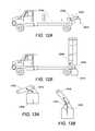
- FIG. 12 aillustrates an exemplary boom configuration which limits the rotation of the X-ray source
- FIG. 12 billustrates another exemplary boom configuration which limits the rotation of the X-ray source
- FIG. 13 aillustrates an exemplary mechanism for minimizing the swinging movement of the X-ray source during boom deployment
- FIG. 13 billustrates another exemplary mechanism for minimizing the swinging movement of the X-ray source during boom deployment
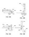
- FIG. 14 aillustrates a configuration for mounting the X-ray source
- FIG. 14 billustrates an alternative configuration for mounting the X-ray source
- FIG. 15 aillustrates an exemplary locking mechanism for the boom and the X-ray source
- FIG. 15 billustrates another exemplary locking mechanism for the boom and the X-ray source
- FIG. 16 aillustrates an alignment of x-ray beam with the detectors
- FIG. 16 billustrates another alignment of x-ray beam with the detectors
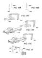
- FIG. 17 aillustrates an exemplary configuration in which the scanning system of the present invention may be deployed
- FIG. 17 billustrates another exemplary configuration in which the scanning system of the present invention may be deployed
- FIG. 17 cillustrates another exemplary configuration in which the scanning system of the present invention may be deployed
- FIG. 18illustrates an exemplary sensor configuration for control of the X-ray system when operating in drive through mode according to one embodiment of the present invention
- FIG. 19shows an exemplary location of three vision targets, with respect to a vehicle being inspected
- FIG. 20shows the output from a scanning laser sensor as a function of time
- FIG. 21illustrates an embodiment where a process logic controller (PLC) is used to control the traffic control and X-ray control mechanism in the scanning system of the present invention
- FIG. 22illustrates an exemplary detector configuration according to one embodiment of the present invention
- FIG. 23illustrates another exemplary configuration wherein the detectors are stacked, according to one embodiment of the present invention.
- FIG. 24shows a side elevation view of the mobile inspection vehicle of the present invention comprising an inspection pod in accordance with one embodiment
- FIG. 25 ashows top view of the mobile inspection vehicle of the present invention comprising an inspection pod in retractable state for travel;
- FIG. 25 bshows top view of the mobile inspection vehicle of the present invention comprising the inspection pod in extendable state during deployment/operation;
- FIG. 26 ashows a side elevation view of the mobile inspection vehicle of the present invention comprising inspection pod accessible to an inspector that can be seated above front wheel level;
- FIG. 26 bshows top view of the mobile inspection vehicle of the present invention comprising inspection pod accessible to an inspector that can be seated above front wheel level;
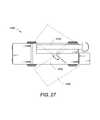
- FIG. 27shows top view of the mobile inspection vehicle of the present invention that has a rotatable bed
- FIG. 28 ashows an embodiment of boom structure/configuration to move pivot point of the boom forward of the rear wheels of the mobile inspection vehicle
- FIG. 28 bshows vertical support of the boom of FIG. 28 a extended in fully vertical orientation along with the horizontal boom being perpendicular to the vertical support;
- FIG. 28 cshows the horizontal boom of the boom of FIG. 28 a being rotated 90 degrees to be perpendicular to the long side of the mobile vehicle;
- FIG. 28 dshows the vertical boom of the boom of FIG. 28 a being lowered down to complete full deployment
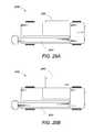
- FIG. 29 ashows an embodiment of structure/configuration of boom, when in stowed condition, in accordance with another aspect of the present invention
- FIG. 29 bshows vertical support of the boom of FIG. 29 a in vertical position along with causing the horizontal boom to extend outwards in a direction perpendicular to the long edge of the vehicle;
- FIG. 29 cshows the vertical boom of the boom of FIG. 29 a being lowered down to complete full deployment
- FIG. 30shows an embodiment of the boom structure/configuration of the present invention where the boom is deployed using an onboard crane
- FIG. 31 ashows an embodiment of the boom structure/configuration of the present invention comprising four components
- FIG. 31 bshows the two vertical support sections of the boom of FIG. 31 a unfolded into an end-to-end configuration
- FIG. 31 cshows the horizontal boom of the boom of FIG. 31 a being extended perpendicular to the long edge of the vehicle through 90 degrees rotatory motion of the rotating platform;
- FIG. 31 dshows an embodiment of the boom of FIG. 31 a where the upper vertical support is telescopically retractable/extendable to/from the lower vertical support;
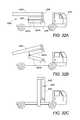
- FIG. 32 ashows an embodiment of the boom structure/configuration of the present invention comprising four components
- FIG. 32 bshows the two vertical support sections of the boom of FIG. 32 a extended from horizontal (stowed position) to vertical position;
- FIG. 32 cshows the folded horizontal and vertical boom sections of the boom of FIG. 32 a being moved from horizontal to vertical orientation.
- the present inventionis directed towards a portable inspection system for generating an image representation of target objects using a radiation source, comprising a mobile vehicle; a detector array physically attached to a single, movable boom having a proximal end and a distal end and at least one source of radiation wherein the radiation source is fixedly attached to the proximal end of the boom and adjustable to a desired scanning height.
- the imageis generated by introducing target objects between the radiation source and the detector array, thereby exposing objects to radiation and subsequently detecting the radiation.
- the boomcan be unfolded from a first stowed configuration to a second deployed and operational configuration.
- the present inventionis directed toward a new boom configuration for the mobile inspection system, which addresses many of the issues that affect boom designs known in the art.
- the boom design of the present inventionprovides for a light weight scanning system, and the boom can also be stowed in a compact manner. This makes the resulting mobile inspection vehicle highly maneuverable. Further, owing to its low axle weights, the mobile inspection vehicle is not subject to any road restrictions and can freely move across all territories in the world.
- a computing device with a graphical user interfaceis deployed to receive user commands, transmit user commands to controllers that are in data communication with the various boom, bracket, winch, and/or hydraulic components described herein, and receive data from the controllers indicative of the state of each of the various boom, bracket, winch, and/or hydraulic components described herein.
- Any computing device and controller systemcan be used, including laptops, mobile devices, desktop components, and X-ray control centers, and any form of data communication can be used, including wired or wireless communications.
- FIG. 1illustrates the mobile inspection vehicle 101 of the present invention in its normal transportation mode wherein the boom 102 is stowed on the vehicle.
- the inspection vehicle 101is a truck and the boom 102 in the stowed condition lies substantially parallel to the bed 103 of the truck 101 .
- the cab 104 of the truckis the highest part of the vehicle, and is typically at an approximate height of 2.6 m from the ground to the highest point.
- the boom 102 of the present inventionis designed such that it is capable of being folded to fit into a space lower than the height of the cab 104 , that is, the highest part of the boom 102 does not exceed the height of the drive cab 104 .
- the maximum standard overall vehicle dimension of a truckis typically 12 m (L) ⁇ 2.5 m (W) ⁇ 4 m (H).
- the overall footprint of the mobile inspection vehicle 101 , of the present invention, with the compact boom 102 when stowed thereonis 11 m (L) ⁇ 2.5 m (W) ⁇ 4 m (H) in accordance with one embodiment.
- the footprint of the vehicle 101is 8 m (L) ⁇ 2.5 m (W) ⁇ 2.6 m (H).
- the compact design of the vehicle 101 with the stowed boom 102offers a substantially small overall size for the inspection vehicle when used with full size inspection tunnel of 4.6 m (H) ⁇ 3.5 m (W) typically.
- FIG. 2 ashows the boom when fully deployed.
- the boomcomprises three sections: vertical support 201 a (connected to an X-ray source 201 d ), horizontal boom 202 a , and vertical boom 203 a.
- FIG. 2 bshows a side view of the mobile inspection vehicle 200 when it is in use, so that the boom is in deployed condition.
- the boom design of the present inventioncomprises three components—vertical support 201 b (connected to a X-ray source 203 d ), horizontal boom 202 b and vertical boom 203 b , which in the stowed condition can be folded parallel to each other in a manner that the total space occupied by the boom is minimized. Since the boom is collapsible to a small volume (of 1.5 m (H) ⁇ 1.2 m (W) ⁇ 5.0 m (L) in one embodiment) when stowed, the overall height of the inspection vehicle is substantially reduced when configured for transport. In one embodiment, the overall height of the inspection vehicle is about 2.6 m during transport when compared to a height of 4.0 m for conventional vehicles. This further allows transport of the vehicle by aircraft (such as a C-130 military transporter) for rapid deployment where appropriate.
- aircraftsuch as a C-130 military transporter
- the vertical support sections 201 a , 201 bare manufactured using a strong material, which in one embodiment is steel.
- a strong materialwhich in one embodiment is steel.
- other engineering materialssuch as carbon fiber composite, aluminum or metal-composite structures may also be used.
- An advantage of the boom structure/design of the present inventionis that the overall weight of the mobile inspection vehicle 200 is substantially reduced.
- a full size 4.6 m (H) ⁇ 3.5 m (W) scanning-tunnel vehiclehas a total weight of less than 25,000 kg, preferably less than 20,000 kg, and more preferably less than 15,000 kg.
- this weight of the mobile inspection vehicle of the present inventionis substantially less when compared to a standard prior art truck that would typically weigh in excess of 25,000 kg.
- the lighter vehicle 200 of the present inventionadvantageously allows the vehicle/truck to operate with a single front axle and a single rear axle.
- the vehicle 200 of the present inventionis much more capable of operating in rugged terrain than conventional prior art designs.
- FIGS. 3 a and 3 bThe functioning of the vertical support is further detailed in FIGS. 3 a and 3 b .
- the vertical support 301 ais in a near horizontal position when not deployed.
- the vertical support 301 ais at an angle in the range of 5 to 20 degrees to the horizontal, when in stowed away position.
- a fixed point 302 ais provided, around which the vertical support is enabled to pivot around.
- the position of the vertical support 301 achanges from near horizontal in FIG. 3 a to vertical as depicted by 301 b in FIG. 3 b.
- the rotating action of the vertical support over the fixed point 302 a , 302 bcan be driven by a number of mechanisms including, but not restricted to, one or more hydraulic rams, one or more electric motors and associated gearboxes or a pulley drive system. It is preferable to be able to lock the vertical support in place once it has been rotated to the operating or stowed condition. This can be achieved by using, by way of example, conical pins (not shown) that pass through a support structure on the truck platform and into suitably located holes in the vertical support.
- conical pinsnot shown
- One of ordinary skill in the artwould appreciate that other locking mechanisms known in the art can also be used in place of or in addition to the example given.
- the X-ray source of the scanning systemis mounted rigidly to the base of the vertical support such that it swings close to the road surface once the vertical support is deployed. This is illustrated in FIG. 4 a .
- the X-ray source 401 ais mounted in an offset position on the vertical support 402 a , such that the focal point 403 a of the X-ray source is in line with the X-ray detectors (not shown) that, in one embodiment, are mounted into the horizontal and vertical boom structures (not shown in FIG. 4 a ).
- the radiation sourceis positioned on the vertical support, which is a portion of the boom proximate to the truck, thereby offering a better alignment between the source and the detectors.
- the radiation sourceis placed either on the truck itself, such as on the side or back of the truck, or on the distal end of the boom.
- FIG. 4 bshows the X-ray source 401 b along with the vertical support 402 b in the stowed position. It may be noted from FIG. 4 b that substantially all of the weight of the vertical support 402 b acts over, is in alignment with, or is otherwise positioned over the rear axle 404 b of the truck. Therefore, the vertical support 402 b is designed to minimize the overall weight of the mobile inspection vehicle in order to ensure that the rear axle loading is kept to a reasonable level.
- FIG. 28 ashows a boom structure/configuration to move pivot point 2806 of the boom 2800 forward of the rear wheels 2804 of the mobile inspection vehicle 2810 in accordance with one embodiment of the present invention.
- the boom 2800comprises three components—vertical support 2801 , horizontal boom 2802 and vertical boom 2803 .
- the vertical support 2801is mounted at its lower end to a rotating platform 2805 which is securely fixed onto the inspection vehicle chassis.
- An actuatoris used to move the vertical support 2801 from a substantially horizontal (when stowed) to a vertical orientation about a hinge or pivot point 2806 which is attached to the rotating platform 2805 .
- the horizontal boom 2802is attached at one of its ends to the top of the vertical support 2801 using a pivot pin 2807 .
- a mechanical linkagemaintains the same angle 2820 between the horizontal boom 2802 and vertical support 2801 as the angle 2815 between the vertical support 2801 and the rotating platform 2805 .
- one actuatoris used to extend two booms in one action or substantially concurrently.
- FIG. 28 bshows the vertical support 2801 extended in fully vertical orientation with reference to the rotating platform 2805 along with the horizontal boom 2802 also being perpendicular to the vertical support 2801 .
- another actuatoris used to rotate the rotating platform 2805 through 90 degrees so that the horizontal boom 2802 is perpendicular to the long side 2825 of the vehicle and extending outwards as shown in FIG. 28 c .
- a third actuatoris used to lower the vertical boom 2803 from a hinge point 2822 at the distal end of the horizontal boom 2802 .
- the boom configuration of FIGS. 28 a through 28 d with the boom pivot point 2806 being advantageously forward of the rear wheels 2804reduces rear axle load substantially, thereby making the inspection vehicle 2810 easier to drive and more compact while providing greater protection for the X-ray source (that is mounted at the lower end/base of the vertical support). Lower weight also contributes to faster deployment of the system.
- the rear axle loadingis below 9 tons for a full laden vehicle.
- FIG. 29 ashows a top perspective of another embodiment of structure/configuration of boom 2900 when in stowed condition, in accordance with another aspect of the present invention.
- the boom 2900comprises two components—a first component comprising vertical support 2901 and horizontal boom 2902 and a second component comprising vertical boom 2903 .
- the vertical support 2901 and horizontal boom 2902are fixed at 90 degrees to each other to form one rigid assembly of the first component.
- the vertical boom 2903is hinged from the distal end 2922 of the horizontal boom 2902 .
- the base of vertical support 2901is hinged about a point 2906 which, in one embodiment, is at 45 degrees to the long edge 2925 of the side of the mobile vehicle 2910 .
- Hinging the first component assembly (of the vertical support 2901 and horizontal boom 2902 at a fixed 90 degrees angle to each other) about the point 2906causes the vertical support 2901 to become vertical (during deployment), from its starting horizontal aspect (when stowed), while simultaneously causing the horizontal boom 2902 to extend outwards in a direction perpendicular to the long edge 2925 of the vehicle, as shown in FIG. 29 b .
- the vertical boom 2903is lowered (using an actuator) about a hinge point at the distal end 2922 of the horizontal boom 2902 for complete deployment.
- the vertical support 2901comprising a first portion which is fixed rigidly to the chassis of the vehicle 2910 and a second part which is hinged from the top of the first part.
- the hingewill advantageously extend over an angle of greater than 90 degrees so that the intersection between the vertical support upper part and the horizontal boom 2902 lies nearer to the vehicle chassis.
- FIG. 30shows yet another embodiment of structure/configuration of boom 3000 in accordance with an aspect of the present invention.
- the boom 3000comprises three components—vertical support 3001 , horizontal boom 3002 and vertical boom 3003 .
- the boom 3000 comprising these three componentsis stowed/loaded onto the back of the mobile vehicle 3010 .
- Vehicle 3010is provided with a manually operated crane (not shown), such as a Hiab lift, which is used to lift the boom sections into place to form a static archway 3005 that is used in drive-through portal mode.
- a manually operated cranenot shown
- Hiab liftwhich is used to lift the boom sections into place to form a static archway 3005 that is used in drive-through portal mode.
- an operatorlifts the vertical boom 3003 into position.
- the operatorlifts the vertical support 3001 into position.
- the operatorlifts the horizontal boom 3002 into position such that it forms a ‘bridge’ between the vertical support 3001 and vertical boom 3003 .
- the operatorcan st
- a positioning plate 3015is first placed into position thereby setting an exact pre-determined location for the base of the vertical boom 3003 relative to the vehicle 3010 .
- This positioning plate 3015may be unfolded from the side of the vehicle or it may be placed into position using the vehicle mounted crane.
- the vertical support 3001 and the vertical boom 3003are each hinged from their respective ends of the horizontal boom 3002 to form an assembly.
- the vehicle mounted craneis used to lift the assembly of three components, from stowed condition, into approximate position for deployment. With the assembly suspended on the crane, the vertical support 3001 and vertical boom 3003 are lowered from a substantially horizontal position (that they were in when stowed) to a substantially vertical position using one or more electric or manually operated winches.
- the “inverted U” shaped boom 3000is then lowered into its operating position and the crane removed to its storage position. The boom 3000 is then ready for use.
- the craneis used to lift the assembly up, the vertical support 3001 and vertical boom 3003 are winched back to a substantially horizontal aspect and the thus assembly is stored back on the vehicle 3010 .
- FIG. 31 ashows still another embodiment of structure/configuration of boom 3100 in accordance with another aspect of the present invention.
- the boom 3100comprises four components—lower vertical support 3101 a , upper vertical support 3101 b , horizontal boom 3102 and vertical boom 3103 .
- the lower vertical support 3101 ais rigidly attached to a rotating platform 3105 while an actuator rotates the platform 3105 through 90 degrees in a plane perpendicular to the plane of the lower vertical support 3101 a .
- the upper vertical support 3101 bis attached to the lower vertical support 3101 a using a hinge (not shown) which can rotate the two vertical support sections by 90 degrees with respect to each other.
- the upper vertical support 3101 bis rigidly attached at 90 degrees to the horizontal boom 3102 .
- the vertical boom 3103is hinged at the end 3122 of the horizontal boom 3102 which is farthest from the upper vertical support 3101 b .
- the upper vertical support 3101 bis folded substantially parallel to the lower vertical support 3101 a.
- the two vertical support sections 3101 a , 3101 bare unfolded into an end-to-end configuration (that is, to make a single contiguous vertical support) as shown in FIG. 31 b .
- the rotating platform 3105then rotates the boom 3100 through 90 degrees such that the horizontal boom 3102 extends perpendicular to the long edge of the vehicle 3110 , as illustrated in FIG. 31 c .
- the vertical boom 3103is then unfolded into the vertical direction to complete deployment of the boom, as has been depicted in FIG. 31 a .
- the boom stow sequenceis exactly opposite to the above described deployment process.
- the upper and lower vertical support sections 3101 b , 3101 a respectivelyare replaced by a single vertical support so that the boom is deployed by simply first rotating the boom and then unfolding the vertical boom 3103 .
- upper vertical support 3101 bis telescopically retractable/extendable to/from the lower vertical support 3101 a as shown in FIG. 31 d and is not hinged to the lower vertical support.
- the upper vertical support 3101 bis simply extended vertically upwards; the platform 3105 rotated by 90 degrees and the vertical boom 3103 unfolded into vertical direction.
- FIG. 32 ashows yet another embodiment of structure/configuration of boom 3200 , in stowed condition, in accordance with another aspect of the present invention.
- the boom 3200comprises four components—lower vertical support 3201 a , upper vertical support 3201 b , horizontal boom 3202 and vertical boom 3203 (visible in FIG. 32 c ).
- the lower and upper vertical support sections 3201 a , 3201 b respectivelyare folded back on each other with rotating joints at each of their meeting ends 3204 .
- the horizontal and vertical boom sections 3202 , 3203 respectively,are each folded up to each other while the horizontal boom 3202 is attached to the upper vertical support 3201 b using a pin bearing 3206 .
- an actuatoris used to extend the two vertical support sections 3201 a , 3201 b from the horizontal (stowed position) to vertical position, as shown in FIG. 32 b .
- Thiscauses the folded horizontal and vertical boom sections 3202 , 3203 to move from the horizontal to the vertical orientation, as illustrated in FIG. 32 c .
- An actuatorthen folds out the horizontal boom 3202 to horizontal aspect, taking the vertical boom 3203 with it.
- the vertical boom 3203is lowered about its hinge point at the end 3222 of the horizontal boom 3202 .
- Boom stowadopts the same sequence but in reverse order.
- the lower vertical support 3201 ais mounted on to a rotating platform (not shown) which can be used to set angle of the resultant scanning tunnel (when the boom 3200 is fully deployed) such that it is in the range, typically, of 75 to 90 degrees with respect to the long edge 3225 of the vehicle 3210 .
- X-ray sourceis fixed to the underside of the rotating platform so that it tracks the required beam angle.
- the plurality of actuators, used for deployment or stow sequence of the boom structures of FIGS. 28 through 32 of the present inventionmay be electric motor (with rotary gearbox or linear screw rod actuators), hydraulic cylinder and lever, electric winch and cable (with removable or fixed end points), manual winch and cable (with removable fixed end points) or any other actuators known to those skilled in the art.
- boom deployment anglesare adjustable in the range 75 degrees to 90 degrees with respect to the scanning direction.
- scanning aperture of the boom structures/configurations of FIGS. 28 through 32is typically 2000 mm (H) ⁇ 2000 mm (W) minimum up to 5300 mm (H) ⁇ 4000 mm (W) maximum.
- boomsmay alternatively be configured with a tunnel aperture outside these dimensions, such as 1000 mm (H), 3000 mm (H), 6000 mm (H), 7000 mm (H), 1000 mm (W), 3000 mm (W), 4500 mm (W), 5000 mm (W), 5500 mm (W), 6000 mm (W), 6500 mm (W), and any dimensions in between.
- X-ray sourcesmay be selected from any of the following categories:
- the booms of the present inventionare fitted with position sensors to provide feedback to an automated boom deployment system. These sensors advantageously record when actuator motion is complete at both ends of travel. In one embodiment, redundant sensors are deployed for such measurements to mitigate against sensor failure.
- boom deploymentin less than 2 minutes. Still faster times may be achieved when suitable strengthening components are fitted to the various booms to mitigate actuator load. Further, boom stowage can also be completed in a similar duration of time.
- the horizontal and vertical booms in the scanning system of the present inventionare designed to contain as little material as possible. This allows for minimizing the weight, and hence reduces the tipping moment on the truck chassis.
- Several materialscan be selected for manufacturing the booms, including steel, aluminum and composite materials.
- One of ordinary skill in the artwould appreciate that other suitable light weight materials may also be used for this purpose.
- the boom designutilizes novel lattice structures to ensure low mass in the boom.
- FIGS. 5 a through 5 dillustrate some of the exemplary low mass lattice structures which act to reduce the weight of the booms.
- the boomsare further designed to include a light-tight, but compact housing for the X-ray detector assemblies.
- FIG. 5 aa section of the boom 501 a is shown in cross-section.
- This boom structureutilizes square profile box section components 502 a , or nodes, where three such box section components 502 a are physically connected by a beam section 504 a .
- the sensor box 503 ais mounted to the side of the boom structure using metal support brackets (not shown) which attach to the triangular boom section 501 a.
- FIG. 5 bshows an alternate design in cross-section, wherein the boom has a square cross section 501 b with the sensor components 503 b mounted to the side and is made from four square profile box section components 502 b where the components 502 b are physically connected by a beam section 504 b .
- the sensor box 503 bmay also be possible to mount within the square section 501 b . This, however, would result in a weakening of the structure since the sensor box would need to form a “U” shape to allow unimpeded access of X-rays to the detectors.
- FIG. 5 cshows a further design in which the detector box 503 c is protected within a boom section comprised of two triangular support frames 501 c of the boom.
- Each of the triangular support frames 501 ccomprises three profile box section components 502 c where the components 502 c are physically connected by a beam section 504 c .
- the two triangular sectionsare then further physically connected by beam section 505 c.
- FIG. 5 dshows another design of the boom in which “bulkheads” 504 d are mounted along the length of the boom which itself is formed from box section components 502 d .
- the sensor box 503 din this case is encased within the boom section.
- FIG. 6shows an exemplary design for a combined boom and detector box.
- the boom cross section 601is extended to include a box section 602 for the X-ray detectors by connecting a beam section 608 from one of its three profile box section components 609 where the components 609 are physically connected by beam sections 610 .
- Beam section 608physically connects to a box component 610 , which then connects to a second box component 611 .
- the detector electronics 603are provided with removable access covers 604 on one side and a removable front cover 605 which is substantially transparent to the incoming X-rays 606 . Further, a thin light-tight sheet covering 607 is provided to protect the rear side of the assembly and the side opposite to the access cover.
- the lattice structures for boom and detector box illustrated in FIGS. 5 and 6can be fabricated using any suitable technique known to persons of ordinary skill in the art. As an example, it would be advantageous to fabricate the structure shown in FIG. 6 using a welded fabrication of 50 mm ⁇ 50 mm steel box section components with 2.5 mm wall thickness to which 1 mm thick steel sheet is welded to form the detector enclosure, the detector cover and the access covers.
- the detector boxis lined with a thermal insulation material to minimize thermal shock to the detectors due to change in ambient temperature and also to help in reducing condensation that may occur in particularly cold climates.
- only one common engineering materialis used for boom fabrication. This not only proves cost-effective, but also ensures that uneven deformation in the boom does not occur under change in ambient temperature as may be the case when multiple materials are used in a boom design.
- FIG. 7presents an exemplary design for folding and unfolding boom sections, as used in one embodiment of the present invention.
- a single hydraulic arm 701is used to force the separation of the horizontal boom 702 from the vertical support 703 .
- the separationis facilitated by means of an intermediate rigid coupling 704 which rotates about a point 705 on the vertical support.
- FIGS. 8 a and 8 bAn exemplary locking mechanism is shown in FIGS. 8 a and 8 b .
- the horizontal boom 801 ais extended so that it folds back above the vertical support 802 a .
- FIG. 9shows another boom deployment structure.
- a first end of a support bar 901mounts to a bearing post 902 , which connects vertical support 903 to horizontal boom 904 in an angular configuration.
- the support bar 901connects to the bearing post 902 at the bearing post pivot point 902 a .
- a second end of the support bar 901has integrated therein a pulley 905 , distal to the bearing 902 .
- a cable 906connects to the horizontal boom 904 and passes over the pulley 905 and returns back to a winch 907 which is mounted securely onto the vertical support 903 .
- the winch 907is operated during boom deployment and it acts to pull the horizontal boom 904 away from the vertical support 903 .
- FIG. 9also shows a horizontal boom lock 908 , which may be used to sense when the boom deployment action has completed, so that the winch 907 can be stopped.
- a sensoris deployed in conjunction with the horizontal boom lock 908 to sense a locking action and transmit the sensed locking action to a controller, which then communicates a stop signal to the winch based upon the locked state.
- FIG. 10A further enhancement of this invention is shown in FIG. 10 .
- the support bar 1001is designed such that it can be rotated out of the way once the horizontal boom 1002 has been stowed with the vertical support 1003 using the mechanism of the winch 1004 and cable 1005 . As the support bar 1001 is moved away, it serves to minimize the space taken by the stowed boom.
- FIGS. 11 a and 11 bshow a space saving folding arrangement between the horizontal boom section and vertical boom section, which is illustrated in FIGS. 11 a and 11 b .
- FIG. 11 awhich shows the boom in a deployed state
- a single folding hinge arrangement 1103 ais used at the junction of the horizontal section 1101 a and vertical section 1102 a .
- a locking pin 1104 ais also provided which engages when the booms 1101 a and 1102 a are deployed fully, and acts to minimize mechanical wobble between the two booms.
- a single hydraulic ram 1105 ais used to force the separation of the horizontal section 1101 a from the vertical section 1102 a when unfolding is required.
- boom structures of the present inventionallow requisite accuracy of alignment so that X-ray energy levels of less than 2 MeV can be used while also being adequate enough to penetrate 150 mm of steel, in accordance with one embodiment. Further, as a result of the use of lower X-ray energy levels, the embodiments of the present invention use smaller Linacs when compared to prior art systems, thereby saving on overall weight. As a further result of the cumulative weight savings, the present invention allows for an X-ray mobile inspection system with penetration greater than 120 mm of steel, while weighing less than 15,000 kg.
- the X-ray support bracket 1202 blowers the X-ray source 1201 b towards its final operating point based upon a signal from a controller. This arrangement avoids the rotation of the X-ray source itself for boom deployment.
- the swinging movement of the X-ray source during boom deploymentis also minimized by connecting a hydraulic damping system between the X-ray source bracket and the X-ray source itself.
- a hydraulic cylinder 1301 alinks the X-ray support bracket 1302 a and the X-ray source 1303 a .
- Hydraulic cylinder 1301 acomprises fluid flow valves that are opened during boom deploy and stow, such that the cylinder can change length under the effect of gravitational pull on the X-ray source.
- the vertical support section 1501 ais provided with a first locking element 1502 a , designed to mate with a corresponding, or mating, locking element or fixture 1503 a in the platform assembly 1504 a .
- first locking element 1502 b and the corresponding, or mating, locking element 1503 bare connected in a such a manner that the relative positions of the boom 1501 b and X-ray source 1504 b are fixed exactly.
- a low energy linear accelerator sourcehaving a typical energy in the range of 0.8 MV to 2 MV, is used for the purposes of screening full size cargo in manifest verification.
- a higher energy X-ray sourcetypically with an energy range of 2.5 MV to 6 MV, is used for scanning of full-sized containers.
- the image penetration capability of the X-ray sourceis suitable for detection of a range of illicit materials and devices including narcotics, explosives, currency, alcohol, weapons and improvised explosive devices.
- the inspection system of the present inventionmay also be configured with a gamma-ray source such as Co-60 or Cs-137, to replace the X-ray source.
- the exclusion zoneis an area around the scanner in which general public are not authorized to enter due to the possibility of their getting exposed to doses of radiations scattered during the scanning process.
- the exclusion areais dependent upon the magnitude of current setting the intensity of the radiation source.
- the availability of a large enough area for the “exclusion zone” around the scanner systemis one of the factors that influence the decision of positioning the mobile inspection system.
- FIGS. 16 a and 16 billustrate the X-ray beam 1601 a and 16 b .
- the X-ray beam 1601 ais wide compared to the X-ray detector 1602 a , so that the detector 1602 a is always illuminated regardless of movement of the boom.
- the detector 1602 bis wider than the illuminating beam 1601 b , thereby ensuring continuous illumination at the detector regardless of movement of the boom. In either case, it is advantageous to ensure that the boom design minimizes motion between the source and sensors.
- the X-ray system of the present inventionis designed to operate in rugged conditions such as those employed in military applications.
- the compact nature of the boom designin particular its fold-flat capability, makes the mobile inspection system of the present invention uniquely suited to military applications where it may be frequently required to transport the X-ray system in its stowed condition in aircraft or helicopters. Such frequent transportation is not feasible with other known boom configurations, where the height of the boom in its stowed condition is greater than that allowed for military transport.
- the compact configurationlends a low center of gravity for better stability of the inspection system during road transport, as there is often a need for driving the inspection system in hilly areas, border crossings, and steep mountainous areas.
- the scanning system 1701 ccan be fully integrated with a truck 1702 c for mobile applications.
- This integrated systemis typically used as a drive past scanner in which the X-ray system is driven past a stationary object at controlled speed.
- the boom baseis attached directly to the truck bed or to a trailer which is then integrated with the truck bed.
- a suitable sensor configuration for control of the X-ray system when operating in drive through modeis shown in FIG. 14 .
- the sensor systemis used to execute two functionalities—traffic control and X-ray control.
- the inspection pod 2405is sized at a footprint of about 2 m (L) ⁇ 1 m (W) ⁇ 2.5 m (H) when retracted (during travel) and of about 2 m (L) ⁇ 2 m (W) ⁇ 2.5 m (H) when in extended state during deployment/inspection.
- the sliding pod 2405 of the present inventionenables a smaller footprint during travel while allowing for up to two inspectors to be seated, within, in extended state during inspection or deployment.
- FIG. 27shows a yet another embodiment of the mobile inspection vehicle 2700 of the present invention where the vehicle bed 2705 , that supports the stowed boom 2710 along with the attached X-ray source 2715 can be swivelled or rotated by a plurality of angles in the horizontal plane of the bed.
- the bed 2705is capable of being swivelled to angles that allow deployment of the boom 2710 at customized angles ranging from, say, 70 to 90 degrees with respect to the direction of scan.
- the rotation of the bed 2705is typically controlled, in one embodiment, using electric motor or hydraulic actuator with accompanying sensors to confirm rotation angle.
- the machine vision camera 1807detects vision targets 1809 that are placed on the vertical boom 1810 on the opposite side.
- the vision targets 1809are located such that they correspond to different parts of a cargo vehicle. Therefore, the simultaneous analysis of a number of different targets can be used to identify different parts of the vehicle driving through the inspection aperture.
- a robust control mechanism for switching on the X-ray beam according to the requirementscan be implemented.
- a safety rated process logic controlleris used to control the traffic control and X-ray control mechanism.
- PLCprocess logic controller
- a process logic controller (PLC) 2101takes inputs regarding the vehicle speed from the radar sensors 2102 , compares the values provided by the various radar sensors, and outputs traffic control signals 2103 depending on the drive-through vehicle speed.
- the current vehicle speedis displayed on an electronic sign whose value is updated frequently, such as once per second.
- Such a detector configurationhas a further benefit of allowing dual-energy imaging when provided with an X-ray linear accelerator that is capable of interleaved energy operation. That is, the system can work with small and large accelerators at low and high energy. For example, two energies—of the order of 3 MV and 6 MV may be used in adjacent pulses.
- each pulseis delivered after the object to be inspected has passed exactly one detector width through the X-ray inspection aperture. The vehicle will therefore have completely passed the detector after exactly two X-ray pulses, one at low energy and one at high energy.
- the penetration performanceis somewhat compromised since only one measurement is made at each beam energy and not two, however, this information is very useful in providing materials discrimination performance.
- stacked detectorscan be used to provide further spectral deconvolution of the X-ray beam. This is illustrated in FIG. 23 .
- one set of low energy detectors 2301are located in the path of the X-ray beam 2302 , and a second set of detectors 2303 are shadowed from the X-ray source by the first set of detectors 2301 .
- the second set of detectors 2303can see only the high energy part of the X-ray beam.
- This informationcan be effectively used to provide materials discrimination capability in the scanning system of the present invention.
- both stacked detectors and an interleaved X-ray sourcemay be used to provide an enhanced level of materials discrimination performance.
- spatial resolutionthat can be achieved in the X-ray image depends on the detector configuration chosen and on the focal spot size of the X-ray source.
- the detectorsare configured with an element size in the range of 1 mm to 10 mm and the X-ray source has a focal spot dimension in the range of 0.5 mm to 3 mm. This results in a spatial resolution generally between 1 lp/cm and 5 lp/cm.
- the penetration performancedepends on the energy of the X-ray source.
- the penetration performanceis typically in the range of 20-100 mm for X-ray sources below 450 kVp, between 100 mm and 200 mm for sources in the range of 450 kVp to 2 MV and between 200 mm and 400 mm for sources in the range of 2 MV to 6 MV.
- the gamma-ray detectorsare advantageously also configured to allow them to be switched off while the X-ray source is switched on and then re-enabled once the X-ray beam is switched back off again. This is particularly important when using a pulsed linear accelerator source for X-ray imaging where the gamma-ray detectors can be rendered inactive during the X-ray pulse and re-activated immediately following the pulse.
Landscapes
- Physics & Mathematics (AREA)
- High Energy & Nuclear Physics (AREA)
- Life Sciences & Earth Sciences (AREA)
- General Life Sciences & Earth Sciences (AREA)
- General Physics & Mathematics (AREA)
- Geophysics (AREA)
- Analysing Materials By The Use Of Radiation (AREA)
Abstract
Description
- X-ray tube and generator with 100 kVp to 500 kVp tube voltage and 0.1 mA to 20 mA tube current, including X-ray sources with 160 kV and a penetration of 30 mm of steel.
- 0.8 MV to 2.5 MV linear accelerator source, including those sources with a low output dose rate, typically less than 0.1 Gy/min at 1 m.
- 2.5 MV to 6 MV linear accelerator source with high output dose rate, typically in the range 0.1 Gy/min at 1 m to 10 Gy/min at 1 m.
- X-ray sources with penetration in excess of 120 mm of steel, including 180 mm of penetration and any increment therein.
- X-ray sources of 450 keV with a penetration of approximately 80 mm of steel.
- The boom design allows for more precise linear accelerator to detector alignment. The folded array detector box configuration shortens the distance between X-ray source and the detector, which increases penetration and provides no corner cutoff with less image distortion.
- The unique scanning boom assembly can be deployed at either a ninety or a eighty degree offset to the vehicle inspected. This allows maximum flexibility in the setup of operational area while providing excellent hidden compartment and false wall detection capabilities.
- One person may deploy the boom with a single button; thus the system is safe, reliable and simple. Stowing the boom is done in the same manner.
- The scanning system includes a plurality of CCTV cameras, which provide a view of the operating zone and help maintain safety.
- Two modes of operation are supported—Mobile and Portal, which allow for inspection of stationary as well as moving cargos, respectively.
- A training mode is provided, which offers images from a training library for simulated scans during inspector training.
- The modular design of the scanning boom assembly and imaging system allows it to be easily adapted to truck chassis from several different manufacturers. This allows local trucks to be utilized in various countries and simplifies vehicle maintenance.
Claims (20)
Priority Applications (3)
| Application Number | Priority Date | Filing Date | Title |
|---|---|---|---|
| US14/104,637US9052403B2 (en) | 2002-07-23 | 2013-12-12 | Compact mobile cargo scanning system |
| US14/689,268US10007019B2 (en) | 2002-07-23 | 2015-04-17 | Compact mobile cargo scanning system |
| US15/988,299US10670769B2 (en) | 2002-07-23 | 2018-05-24 | Compact mobile cargo scanning system |
Applications Claiming Priority (17)
| Application Number | Priority Date | Filing Date | Title |
|---|---|---|---|
| US10/201,543US6843599B2 (en) | 2002-07-23 | 2002-07-23 | Self-contained, portable inspection system and method |
| US49393503P | 2003-08-08 | 2003-08-08 | |
| US50249803P | 2003-09-12 | 2003-09-12 | |
| US10/915,687US7322745B2 (en) | 2002-07-23 | 2004-08-09 | Single boom cargo scanning system |
| US10/939,986US7486768B2 (en) | 2002-07-23 | 2004-09-13 | Self-contained mobile inspection system and method |
| US11/622,560US7369643B2 (en) | 2002-07-23 | 2007-01-12 | Single boom cargo scanning system |
| US98478607P | 2007-11-02 | 2007-11-02 | |
| US11/948,814US7517149B2 (en) | 2002-07-23 | 2007-11-30 | Cargo scanning system |
| US1481407P | 2007-12-19 | 2007-12-19 | |
| US12/051,910US7519148B2 (en) | 2002-07-23 | 2008-03-20 | Single boom cargo scanning system |
| US12/263,160US7783004B2 (en) | 2002-07-23 | 2008-10-31 | Cargo scanning system |
| US12/339,591US7963695B2 (en) | 2002-07-23 | 2008-12-19 | Rotatable boom cargo scanning system |
| US12/349,534US7720195B2 (en) | 2002-07-23 | 2009-01-07 | Self-contained mobile inspection system and method |
| US18047109P | 2009-05-22 | 2009-05-22 | |
| US12/784,630US8275091B2 (en) | 2002-07-23 | 2010-05-21 | Compact mobile cargo scanning system |
| US13/598,945US8668386B2 (en) | 2002-07-23 | 2012-08-30 | Compact mobile cargo scanning system |
| US14/104,637US9052403B2 (en) | 2002-07-23 | 2013-12-12 | Compact mobile cargo scanning system |
Related Parent Applications (1)
| Application Number | Title | Priority Date | Filing Date |
|---|---|---|---|
| US13/598,945ContinuationUS8668386B2 (en) | 2002-07-23 | 2012-08-30 | Compact mobile cargo scanning system |
Related Child Applications (1)
| Application Number | Title | Priority Date | Filing Date |
|---|---|---|---|
| US14/689,268ContinuationUS10007019B2 (en) | 2002-07-23 | 2015-04-17 | Compact mobile cargo scanning system |
Publications (2)
| Publication Number | Publication Date |
|---|---|
| US20150110243A1 US20150110243A1 (en) | 2015-04-23 |
| US9052403B2true US9052403B2 (en) | 2015-06-09 |
Family
ID=43588591
Family Applications (5)
| Application Number | Title | Priority Date | Filing Date |
|---|---|---|---|
| US12/784,630Expired - Fee RelatedUS8275091B2 (en) | 2002-07-23 | 2010-05-21 | Compact mobile cargo scanning system |
| US13/598,945Expired - Fee RelatedUS8668386B2 (en) | 2002-07-23 | 2012-08-30 | Compact mobile cargo scanning system |
| US14/104,637Expired - Fee RelatedUS9052403B2 (en) | 2002-07-23 | 2013-12-12 | Compact mobile cargo scanning system |
| US14/689,268Expired - Fee RelatedUS10007019B2 (en) | 2002-07-23 | 2015-04-17 | Compact mobile cargo scanning system |
| US15/988,299Expired - Fee RelatedUS10670769B2 (en) | 2002-07-23 | 2018-05-24 | Compact mobile cargo scanning system |
Family Applications Before (2)
| Application Number | Title | Priority Date | Filing Date |
|---|---|---|---|
| US12/784,630Expired - Fee RelatedUS8275091B2 (en) | 2002-07-23 | 2010-05-21 | Compact mobile cargo scanning system |
| US13/598,945Expired - Fee RelatedUS8668386B2 (en) | 2002-07-23 | 2012-08-30 | Compact mobile cargo scanning system |
Family Applications After (2)
| Application Number | Title | Priority Date | Filing Date |
|---|---|---|---|
| US14/689,268Expired - Fee RelatedUS10007019B2 (en) | 2002-07-23 | 2015-04-17 | Compact mobile cargo scanning system |
| US15/988,299Expired - Fee RelatedUS10670769B2 (en) | 2002-07-23 | 2018-05-24 | Compact mobile cargo scanning system |
Country Status (1)
| Country | Link |
|---|---|
| US (5) | US8275091B2 (en) |
Cited By (23)
| Publication number | Priority date | Publication date | Assignee | Title |
|---|---|---|---|---|
| US20140270450A1 (en)* | 2011-10-24 | 2014-09-18 | Koninklijke Philips N.V. | Motion compensated second pass metal artifact correction for ct slice images |
| US9632206B2 (en) | 2011-09-07 | 2017-04-25 | Rapiscan Systems, Inc. | X-ray inspection system that integrates manifest data with imaging/detection processing |
| US9880314B2 (en) | 2013-07-23 | 2018-01-30 | Rapiscan Systems, Inc. | Methods for improving processing speed for object inspection |
| US10168445B2 (en) | 2015-03-20 | 2019-01-01 | Rapiscan Systems, Inc. | Hand-held portable backscatter inspection system |
| US10209372B2 (en) | 2012-02-14 | 2019-02-19 | American Science And Engineering, Inc. | Hand-held X-ray detection system using wavelength-shifting fiber-coupled scintillation detectors |
| US10228487B2 (en) | 2014-06-30 | 2019-03-12 | American Science And Engineering, Inc. | Rapidly relocatable modular cargo container scanner |
| US10302807B2 (en) | 2016-02-22 | 2019-05-28 | Rapiscan Systems, Inc. | Systems and methods for detecting threats and contraband in cargo |
| US10345479B2 (en) | 2015-09-16 | 2019-07-09 | Rapiscan Systems, Inc. | Portable X-ray scanner |
| US10600609B2 (en) | 2017-01-31 | 2020-03-24 | Rapiscan Systems, Inc. | High-power X-ray sources and methods of operation |
| US10670740B2 (en) | 2012-02-14 | 2020-06-02 | American Science And Engineering, Inc. | Spectral discrimination using wavelength-shifting fiber-coupled scintillation detectors |
| US10830911B2 (en) | 2018-06-20 | 2020-11-10 | American Science And Engineering, Inc. | Wavelength-shifting sheet-coupled scintillation detectors |
| US11143783B2 (en) | 2002-07-23 | 2021-10-12 | Rapiscan Systems, Inc. | Four-sided imaging system and method for detection of contraband |
| US11175245B1 (en) | 2020-06-15 | 2021-11-16 | American Science And Engineering, Inc. | Scatter X-ray imaging with adaptive scanning beam intensity |
| US11193898B1 (en) | 2020-06-01 | 2021-12-07 | American Science And Engineering, Inc. | Systems and methods for controlling image contrast in an X-ray system |
| WO2021246998A1 (en) | 2020-06-01 | 2021-12-09 | American Science And Engineering, Inc. | Systems and methods for controlling image contrast in an x-ray system |
| US11212902B2 (en) | 2020-02-25 | 2021-12-28 | Rapiscan Systems, Inc. | Multiplexed drive systems and methods for a multi-emitter X-ray source |
| US11340361B1 (en) | 2020-11-23 | 2022-05-24 | American Science And Engineering, Inc. | Wireless transmission detector panel for an X-ray scanner |
| US11536871B2 (en) | 2020-03-25 | 2022-12-27 | Smiths Heimann Sas | Vehicle inspection controlled using image information |
| US11796489B2 (en) | 2021-02-23 | 2023-10-24 | Rapiscan Systems, Inc. | Systems and methods for eliminating cross-talk signals in one or more scanning systems having multiple X-ray sources |
| US11802988B2 (en) | 2020-03-25 | 2023-10-31 | Smiths Heimann Sas | Dose-controlled vehicle inspection |
| US12235226B2 (en) | 2012-02-03 | 2025-02-25 | Rapiscan Systems, Inc. | Combined scatter and transmission multi-view imaging system |
| US12283389B2 (en) | 2021-10-01 | 2025-04-22 | Rapiscan Holdings, Inc. | Methods and systems for the concurrent generation of multiple substantially similar X-ray beams |
| US12387900B2 (en) | 2022-02-03 | 2025-08-12 | Rapiscan Holdings, Inc. | Systems and methods for real-time energy and dose monitoring of an X-ray linear accelerator |
Families Citing this family (55)
| Publication number | Priority date | Publication date | Assignee | Title |
|---|---|---|---|---|
| US8275091B2 (en) | 2002-07-23 | 2012-09-25 | Rapiscan Systems, Inc. | Compact mobile cargo scanning system |
| US8503605B2 (en) | 2002-07-23 | 2013-08-06 | Rapiscan Systems, Inc. | Four sided imaging system and method for detection of contraband |
| US7963695B2 (en) | 2002-07-23 | 2011-06-21 | Rapiscan Systems, Inc. | Rotatable boom cargo scanning system |
| US6928141B2 (en) | 2003-06-20 | 2005-08-09 | Rapiscan, Inc. | Relocatable X-ray imaging system and method for inspecting commercial vehicles and cargo containers |
| US7471764B2 (en) | 2005-04-15 | 2008-12-30 | Rapiscan Security Products, Inc. | X-ray imaging system having improved weather resistance |
| US7526064B2 (en) | 2006-05-05 | 2009-04-28 | Rapiscan Security Products, Inc. | Multiple pass cargo inspection system |
| CN101470083B (en)* | 2007-12-27 | 2011-08-03 | 同方威视技术股份有限公司 | New folding arm mechanism for vehicle-mounted radiation imaging system |
| GB0803641D0 (en) | 2008-02-28 | 2008-04-02 | Rapiscan Security Products Inc | Scanning systems |
| GB0809110D0 (en) | 2008-05-20 | 2008-06-25 | Rapiscan Security Products Inc | Gantry scanner systems |
| US9310323B2 (en) | 2009-05-16 | 2016-04-12 | Rapiscan Systems, Inc. | Systems and methods for high-Z threat alarm resolution |
| US8798963B2 (en)* | 2009-06-04 | 2014-08-05 | Siemens Industry, Inc. | Container transport monitoring and analysis |
| CN103354911A (en)* | 2010-08-16 | 2013-10-16 | 地面探测器有限公司 | Work area monitor |
| EP3252506B1 (en) | 2011-02-08 | 2020-11-18 | Rapiscan Systems, Inc. | Covert surveillance using multi-modality sensing |
| US8908831B2 (en) | 2011-02-08 | 2014-12-09 | Rapiscan Systems, Inc. | Covert surveillance using multi-modality sensing |
| DE102011013942A1 (en) | 2011-03-14 | 2012-09-20 | Smiths Heimann Gmbh | Installation for the inspection of large-volume goods, in particular freight |
| US9218933B2 (en) | 2011-06-09 | 2015-12-22 | Rapidscan Systems, Inc. | Low-dose radiographic imaging system |
| CA3078087C (en)* | 2011-06-14 | 2021-11-02 | Rapiscan Systems, Inc. | Covert surveillance using multi-modality sensing |
| WO2013003687A2 (en)* | 2011-06-29 | 2013-01-03 | L-3 Communications Security And Detection Systems, Inc. | Vehicle-mounted cargo inspection system |
| US8939697B2 (en)* | 2011-10-31 | 2015-01-27 | Quickthree Solutions, Inc. | Selective orientation and ballast for a transportable container |
| JP2013156172A (en)* | 2012-01-31 | 2013-08-15 | X-Ray Precision Inc | X-ray inspection apparatus |
| US9274065B2 (en)* | 2012-02-08 | 2016-03-01 | Rapiscan Systems, Inc. | High-speed security inspection system |
| EP2812735A2 (en)* | 2012-02-10 | 2014-12-17 | Smiths Heimann GmbH | Method and device for inspecting the cargo space of a truck |
| US8888422B2 (en)* | 2012-04-16 | 2014-11-18 | Nathan Miller | Locking system for roll-off containers |
| JP6385369B2 (en) | 2013-01-31 | 2018-09-05 | ラピスカン システムズ、インコーポレイテッド | Transportable safety inspection system |
| US9630816B1 (en)* | 2013-03-11 | 2017-04-25 | Oz Lifting Products, LLC | Portable crane formed of composite members |
| US9689814B2 (en)* | 2013-03-19 | 2017-06-27 | Battelle Energy Alliance, Llc | Chemical detection system and related methods |
| US9557427B2 (en) | 2014-01-08 | 2017-01-31 | Rapiscan Systems, Inc. | Thin gap chamber neutron detectors |
| US9989668B2 (en)* | 2014-01-22 | 2018-06-05 | Nuctech Company Limited | Inspection system for container |
| RO130582B1 (en)* | 2014-01-23 | 2021-12-30 | Mb Telecom Ltd. S.R.L. | System and method for complete and non-intrusive inspection of aircrafts |
| CN103984035A (en)* | 2014-05-15 | 2014-08-13 | 北京君和信达科技有限公司 | A dual-mode speed-through radiation inspection system and method for moving targets |
| US10459111B2 (en)* | 2014-05-23 | 2019-10-29 | Radiabeam Technologies, Llc | System and method for adaptive X-ray cargo inspection |
| CN104459811B (en)* | 2014-12-11 | 2017-12-22 | 同方威视技术股份有限公司 | Vehicle-mounted removable container or vehicle inspection system |
| CN104459813B (en) | 2014-12-29 | 2019-08-23 | 清华大学 | Vehicular quickly checks system |
| US9836118B2 (en) | 2015-06-16 | 2017-12-05 | Wilson Steele | Method and system for analyzing a movement of a person |
| CN105607046B (en)* | 2015-12-22 | 2018-03-06 | 北京无线电计量测试研究所 | A kind of large-scale scanning frame for compact antenna test range and test system |
| CN105548223B (en)* | 2015-12-23 | 2019-07-02 | 清华大学 | Scanning method, scanning system and radiation scanning controller |
| US10429001B2 (en)* | 2016-08-22 | 2019-10-01 | Altec Industries, Inc. | Stable mobile scanner |
| EP3505919B1 (en)* | 2016-08-25 | 2024-07-17 | Beijing Hualixing Technology Development Co., Ltd. | Imaging device for use in vehicle security check and method therefor |
| CN106483578B (en) | 2016-11-25 | 2019-03-29 | 同方威视技术股份有限公司 | Mobile scanning-detecting system |
| CN106772650A (en)* | 2016-12-26 | 2017-05-31 | 同方威视技术股份有限公司 | Portable explosive transmission imaging device |
| CN107064186B (en)* | 2017-04-17 | 2023-11-10 | 北京一体通探测技术有限公司 | Work platform of vehicle-mounted security inspection equipment and vehicle-mounted security inspection equipment with same |
| CN108398726A (en)* | 2018-05-09 | 2018-08-14 | 清华大学 | Radiation checking system and port facilities |
| CN110327070B (en)* | 2019-07-12 | 2024-07-12 | 山东大骋医疗科技有限公司 | CT apparatus with energy storage system |
| CN110764155A (en)* | 2019-10-30 | 2020-02-07 | 南京全设智能科技有限公司 | Self-adaptive security check equipment based on transmission speed change and control method thereof |
| CN210954365U (en)* | 2019-10-30 | 2020-07-07 | 南京全设智能科技有限公司 | Security check equipment based on transmission speed change self-adaptation |
| JP7222880B2 (en)* | 2019-12-26 | 2023-02-15 | キヤノン電子管デバイス株式会社 | X-ray tube packaging device |
| GB202012182D0 (en)* | 2020-08-05 | 2020-09-16 | 2Xsystems Ltd | Boom apparatus and an article scanning system |
| CN114764069B (en)* | 2020-12-31 | 2024-10-11 | 同方威视技术股份有限公司 | Radiation inspection system |
| CN113392695B (en)* | 2021-04-02 | 2023-04-25 | 太原理工大学 | A road truck and its axle identification method |
| US11827498B1 (en) | 2021-04-22 | 2023-11-28 | National Technology & Engineering Solutions Of Sandia, Llc | Portable positional scanning lane |
| CN114137622A (en)* | 2021-12-30 | 2022-03-04 | 同方威视科技(北京)有限公司 | Mobile radiation inspection apparatus and mobile radiation inspection system |
| CN114167509B (en)* | 2021-12-30 | 2025-07-15 | 同方威视科技(北京)有限公司 | Mobile inspection equipment and mobile inspection method |
| EP4562413A1 (en) | 2022-07-26 | 2025-06-04 | Rapiscan Holdings, Inc. | Methods and systems for performing on-the-fly automatic calibration adjustments of x-ray inspection systems |
| GB2635769A (en)* | 2023-11-27 | 2025-05-28 | Smiths Detection France S A S | Structure for inspection system |
| GB2635770A (en)* | 2023-11-27 | 2025-05-28 | Smiths Detection France S A S | Platform module for inspection system |
Citations (615)
| Publication number | Priority date | Publication date | Assignee | Title |
|---|---|---|---|---|
| US2420845A (en) | 1944-06-15 | 1947-05-20 | Westinghouse Electric Corp | Short exposure x-ray apparatus |
| US2636619A (en) | 1950-02-07 | 1953-04-28 | Charles E Alexander | Vehicle hoist |
| US2831123A (en) | 1956-07-11 | 1958-04-15 | Webster J Daly | X-ray fluoroscopic device |
| US2885069A (en) | 1954-11-19 | 1959-05-05 | William V Bowen | Conveyor belt cleaning apparatus |
| US2952790A (en) | 1957-07-15 | 1960-09-13 | Raytheon Co | X-ray tubes |
| US2971433A (en) | 1959-01-07 | 1961-02-14 | Royal H Akin | Transistorized photomultiplier photometer circuit |
| US3070399A (en) | 1961-02-03 | 1962-12-25 | David L Bartlett | Expandable house trailer |
| US3073960A (en) | 1958-07-14 | 1963-01-15 | Westinghouse Electric Corp | Teletherapy device |
| US3146349A (en) | 1961-12-01 | 1964-08-25 | Edward D Jordan | Detecting hidden explosives using neutron beams |
| US3239706A (en) | 1961-04-17 | 1966-03-08 | High Voltage Engineering Corp | X-ray target |
| US3275831A (en) | 1963-05-16 | 1966-09-27 | Industrial Nucleonics Corp | Radiation beam shutter collimator |
| US3374355A (en) | 1946-02-21 | 1968-03-19 | Atomic Energy Commission Usa | Magnetic focusing of x-ray tubes and system for operating |
| US3458026A (en) | 1966-03-28 | 1969-07-29 | Taylor & Gaskin | Article spacer |
| US3485339A (en) | 1967-12-11 | 1969-12-23 | Fairbank Morse Inc | Article spacing system |
| US3676783A (en) | 1968-04-23 | 1972-07-11 | Japan Atomic Energy Res Inst | Waveform discriminating circuit |
| US3766387A (en) | 1972-07-11 | 1973-10-16 | Us Navy | Nondestructive test device using radiation to detect flaws in materials |
| US3767850A (en) | 1972-02-22 | 1973-10-23 | Abbott Lab | Graphic recording apparatus and method |
| US3768645A (en) | 1971-02-22 | 1973-10-30 | Sunkist Growers Inc | Method and means for automatically detecting and sorting produce according to internal damage |
| US3770955A (en) | 1970-09-17 | 1973-11-06 | Hitachi Roentgen | Tomographic apparatus |
| US3784837A (en) | 1972-05-08 | 1974-01-08 | Siemens Ag | X-ray device with a stand |
| US3837502A (en) | 1973-03-12 | 1974-09-24 | Bucyrus Erie Co | Light weight boom construction |
| USRE28544E (en) | 1971-07-07 | 1975-09-02 | Radiant energy imaging with scanning pencil beam | |
| US3904923A (en) | 1974-01-14 | 1975-09-09 | Zenith Radio Corp | Cathodo-luminescent display panel |
| US3919467A (en) | 1973-08-27 | 1975-11-11 | Ridge Instr Company Inc | X-ray baggage inspection system |
| US3955678A (en) | 1974-08-09 | 1976-05-11 | American Chain & Cable Company, Inc. | Sorting system |
| US3961186A (en) | 1973-10-09 | 1976-06-01 | Ib Leunbach | Method and apparatus for the determination of electron density in a part volume of a body |
| US3980889A (en) | 1974-04-08 | 1976-09-14 | North American Philips Corporation | Article transfer and inspection apparatus |
| FR2328280A1 (en) | 1975-10-18 | 1977-05-13 | Emi Ltd | Scanning X:ray machine - has electron source moved along target electrode bent into circular arc |
| US4047035A (en) | 1975-07-18 | 1977-09-06 | Heimann Gmbh | Baggage inspection device |
| US4057725A (en) | 1974-09-06 | 1977-11-08 | U.S. Philips Corporation | Device for measuring local radiation absorption in a body |
| US4064440A (en) | 1976-06-22 | 1977-12-20 | Roder Frederick L | X-ray or gamma-ray examination device for moving objects |
| GB1497396A (en) | 1974-03-23 | 1978-01-12 | Emi Ltd | Radiography |
| US4105922A (en) | 1977-04-11 | 1978-08-08 | General Electric Company | CT number identifier in a computed tomography system |
| GB1526041A (en) | 1975-08-29 | 1978-09-27 | Emi Ltd | Sources of x-radiation |
| DE2729353A1 (en) | 1977-06-29 | 1979-01-11 | Siemens Ag | X=ray tube with migrating focal spot for tomography appts. - has shaped anode, several control grids at common potential and separately switched cathode |
| US4139771A (en) | 1975-07-18 | 1979-02-13 | Heimann Gmbh | Device for examining luggage by means of X-rays |
| US4164138A (en) | 1977-10-27 | 1979-08-14 | Smith & Denison | High sensitivity gas leak detection system |
| GB2015245A (en) | 1978-02-23 | 1979-09-05 | Philips Nv | X-ray tubes |
| US4210811A (en) | 1975-11-03 | 1980-07-01 | Heimann Gmbh | Drive for moveable shield in luggage screening apparatus |
| US4216499A (en) | 1977-08-05 | 1980-08-05 | Heimann Gmbh | Inspection system for baggage |
| US4228353A (en) | 1978-05-02 | 1980-10-14 | Johnson Steven A | Multiple-phase flowmeter and materials analysis apparatus and method |
| US4259721A (en) | 1977-02-10 | 1981-03-31 | Siemens Aktiengesellschaft | Computer system for the image synthesis of a transverse body section and method for the operation of the computer system |
| US4266425A (en) | 1979-11-09 | 1981-05-12 | Zikonix Corporation | Method for continuously determining the composition and mass flow of butter and similar substances from a manufacturing process |
| US4274005A (en) | 1978-09-29 | 1981-06-16 | Tokyo Shibaura Denki Kabushiki Kaisha | X-ray apparatus for computed tomography scanner |
| US4340816A (en) | 1976-10-19 | 1982-07-20 | Siemens Aktiengesellschaft | Method of producing tomograms with x-rays or similarly penetrating radiation |
| US4352021A (en) | 1980-01-07 | 1982-09-28 | The Regents Of The University Of California | X-Ray transmission scanning system and method and electron beam X-ray scan tube for use therewith |
| US4366382A (en) | 1980-09-09 | 1982-12-28 | Scanray Corporation | X-Ray line scan system for use in baggage inspection |
| US4380817A (en) | 1979-09-27 | 1983-04-19 | U.S. Philips Corporation | Method for examining a body with penetrating radiation |
| EP0077018A1 (en) | 1981-10-09 | 1983-04-20 | Heimann GmbH | Device to produce X-ray images of an object |
| US4430568A (en) | 1980-09-22 | 1984-02-07 | Mitsubishi Denki Kabushiki Kaisha | Container inspection system |
| JPS5916254B2 (en) | 1977-05-31 | 1984-04-14 | ポラロイド コ−ポレ−シヨン | fixed focus photographic camera device |
| US4468802A (en) | 1981-03-02 | 1984-08-28 | Siemens Aktiengesellschaft | X-Ray tube |
| US4481403A (en) | 1983-03-04 | 1984-11-06 | Honeywell Inc. | Temperature control of solid state circuit chips |
| US4501011A (en) | 1982-09-22 | 1985-02-19 | General Electric Company | Angulating lateral fluoroscopic suspension |
| GB2089109B (en) | 1980-12-03 | 1985-05-15 | Machlett Lab Inc | X-rays targets and tubes |
| US4525854A (en) | 1983-03-22 | 1985-06-25 | Troxler Electronic Laboratories, Inc. | Radiation scatter apparatus and method |
| US4563707A (en) | 1983-09-08 | 1986-01-07 | Dainippon Screen Mfg. Co., Ltd. | Method and system for regulating the maximum output current of a photomultiplier |
| US4566113A (en) | 1981-11-13 | 1986-01-21 | Heimann Gmbh | Method and apparatus for examining the content of containers |
| US4599740A (en) | 1983-01-06 | 1986-07-08 | Cable Arthur P | Radiographic examination system |
| US4626688A (en) | 1982-11-26 | 1986-12-02 | Barnes Gary T | Split energy level radiation detection |
| US4641330A (en) | 1984-08-23 | 1987-02-03 | Heimann Gmbh | High voltage supply circuit for an x-ray tube |
| US4672649A (en) | 1984-05-29 | 1987-06-09 | Imatron, Inc. | Three dimensional scanned projection radiography using high speed computed tomographic scanning system |
| US4675890A (en) | 1982-10-05 | 1987-06-23 | Thomson-Csf | X-ray tube for producing a high-efficiency beam and especially a pencil beam |
| US4709382A (en) | 1984-11-21 | 1987-11-24 | Picker International, Inc. | Imaging with focused curved radiation detectors |
| EP0261984A2 (en) | 1986-09-26 | 1988-03-30 | Max Robinson | Three-dimensional visual screening system |
| US4736401A (en) | 1985-04-03 | 1988-04-05 | Heimann Gmbh | X-ray scanner |
| US4752948A (en) | 1986-12-01 | 1988-06-21 | University Of Chicago | Mobile radiography alignment device |
| US4788704A (en) | 1985-03-04 | 1988-11-29 | Heimann Gmbh | X-ray scanner & detector signal processing system |
| US4799247A (en) | 1986-06-20 | 1989-01-17 | American Science And Engineering, Inc. | X-ray imaging particularly adapted for low Z materials |
| US4809312A (en) | 1986-07-22 | 1989-02-28 | American Science And Engineering, Inc. | Method and apparatus for producing tomographic images |
| US4809857A (en) | 1987-08-10 | 1989-03-07 | Fmc Corporation | Drum rotation indicator |
| US4817123A (en) | 1984-09-21 | 1989-03-28 | Picker International | Digital radiography detector resolution improvement |
| US4825454A (en) | 1987-12-28 | 1989-04-25 | American Science And Engineering, Inc. | Tomographic imaging with concentric conical collimator |
| US4831260A (en) | 1987-10-09 | 1989-05-16 | University Of North Caroline At Chapel Hill | Beam equalization method and apparatus for a kinestatic charge detector |
| USRE32961E (en) | 1974-09-06 | 1989-06-20 | U.S. Philips Corporation | Device for measuring local radiation absorption in a body |
| US4853595A (en) | 1987-08-31 | 1989-08-01 | Alfano Robert R | Photomultiplier tube having a transmission strip line photocathode and system for use therewith |
| US4864142A (en) | 1988-01-11 | 1989-09-05 | Penetron, Inc. | Method and apparatus for the noninvasive interrogation of objects |
| US4866745A (en) | 1986-07-16 | 1989-09-12 | Agency Of Industrial Science & Technology, Ministry Of International Trade & Industry | Ultrahigh speed X-ray CT scanner |
| US4866439A (en) | 1987-03-27 | 1989-09-12 | Kraus John H | Explosives detection system for an aircraft |
| US4868856A (en) | 1985-08-27 | 1989-09-19 | National Research Development Corporation | Multi-component flow measurement and imaging |
| US4870670A (en) | 1987-10-19 | 1989-09-26 | Heimann Gmbh | X-ray scanner with secondary radiation detector |
| US4872188A (en) | 1987-11-27 | 1989-10-03 | Picker International, Inc. | Registration correction for radiographic scanners with sandwich detectors |
| US4879735A (en) | 1988-05-31 | 1989-11-07 | Owens Robert W | Baggage inspection conveyor baffle and method |
| US4884289A (en) | 1986-05-28 | 1989-11-28 | Heimann Gmbh | X-ray scanner for detecting plastic articles |
| US4887604A (en) | 1988-05-16 | 1989-12-19 | Science Research Laboratory, Inc. | Apparatus for performing dual energy medical imaging |
| US4979202A (en) | 1989-08-25 | 1990-12-18 | Siczek Aldona A | Support structure for X-ray imaging apparatus |
| US4979137A (en) | 1986-11-18 | 1990-12-18 | Ufa Inc. | Air traffic control training system |
| DE3214910C2 (en) | 1981-10-26 | 1991-01-10 | Windmoeller & Hoelscher, 4540 Lengerich, De | |
| US4987584A (en) | 1989-04-06 | 1991-01-22 | Heiman Gmbh | Materials inspection system using x-ray imaging |
| US4991189A (en) | 1990-04-16 | 1991-02-05 | General Electric Company | Collimation apparatus for x-ray beam correction |
| US4991708A (en) | 1988-05-18 | 1991-02-12 | Cavanna S.P.A. | Apparatus for forming groups of articles, particularly for automatic packaging lines |
| EP0417965A2 (en) | 1989-09-06 | 1991-03-20 | General Electric Company | An X-ray mammography system |
| US5006299A (en) | 1987-05-26 | 1991-04-09 | Science Applications International Corporation | Explosive detection system |
| US5014293A (en) | 1989-10-04 | 1991-05-07 | Imatron, Inc. | Computerized tomographic x-ray scanner system and gantry assembly |
| US5022062A (en) | 1989-09-13 | 1991-06-04 | American Science And Engineering, Inc. | Automatic threat detection based on illumination by penetrating radiant energy using histogram processing |
| EP0432568A2 (en) | 1989-12-11 | 1991-06-19 | General Electric Company | X ray tube anode and tube having same |
| US5033106A (en) | 1986-10-27 | 1991-07-16 | Sharp Kabushiki Kaisha | Information registering and retrieval system |
| US5040199A (en) | 1986-07-14 | 1991-08-13 | Hologic, Inc. | Apparatus and method for analysis using x-rays |
| GB2212903B (en) | 1987-11-24 | 1991-11-06 | Rolls Royce Plc | Measuring two phase flow in pipes. |
| US5065418A (en) | 1989-08-09 | 1991-11-12 | Heimann Gmbh | Apparatus for the transillumination of articles with fan-shaped radiation |
| US5067145A (en) | 1990-03-16 | 1991-11-19 | Siczek Bernard W | Mobile X-ray apparatus |
| US5076993A (en) | 1990-01-12 | 1991-12-31 | Science Applications International Corporation | Contraband detection system using direct imaging pulsed fast neutrons |
| US5086300A (en) | 1990-05-29 | 1992-02-04 | Ashmore George A | Method and system for passive detection of electromagnetic events associated with destructive devices |
| US5091924A (en) | 1989-08-09 | 1992-02-25 | Heimann Gmbh | Apparatus for the transillumination of articles with a fan-shaped radiation beam |
| US5092451A (en) | 1987-10-01 | 1992-03-03 | Logan Fenamec (Uk) Limited | Method of and apparatus for separating articles conveyed on a conveyor system |
| US5098640A (en) | 1990-01-10 | 1992-03-24 | Science Applications International Corporation | Apparatus and method for detecting contraband using fast neutron activation |
| US5097939A (en) | 1989-11-03 | 1992-03-24 | Shanklin Corporation | Synchronous position product feed system |
| US5114662A (en) | 1987-05-26 | 1992-05-19 | Science Applications International Corporation | Explosive detection system |
| EP0176314B1 (en) | 1984-09-21 | 1992-06-10 | Picker International, Inc. | Radiography system |
| US5144191A (en) | 1991-06-12 | 1992-09-01 | Mcnc | Horizontal microelectronic field emission devices |
| GB2255634A (en) | 1991-05-10 | 1992-11-11 | British Steel Plc | Photomultiplier tube for thickness measurement |
| US5179581A (en) | 1989-09-13 | 1993-01-12 | American Science And Engineering, Inc. | Automatic threat detection based on illumination by penetrating radiant energy |
| US5181234A (en) | 1990-08-06 | 1993-01-19 | Irt Corporation | X-ray backscatter detection system |
| US5182764A (en) | 1991-10-03 | 1993-01-26 | Invision Technologies, Inc. | Automatic concealed object detection system having a pre-scan stage |
| US5185778A (en) | 1991-08-13 | 1993-02-09 | Magram Martin Y | X-ray shielding apparatus |
| US5202932A (en) | 1990-06-08 | 1993-04-13 | Catawa Pty. Ltd. | X-ray generating apparatus and associated method |
| US5221843A (en) | 1992-04-23 | 1993-06-22 | Alvarez Robert E | Active energy selective x-ray image detection |
| US5224144A (en) | 1991-09-12 | 1993-06-29 | American Science And Engineering, Inc. | Reduced mass flying spot scanner having arcuate scanning lines |
| US5237598A (en) | 1992-04-24 | 1993-08-17 | Albert Richard D | Multiple image scanning X-ray method and apparatus |
| US5243693A (en) | 1989-11-28 | 1993-09-07 | Israel Military Industries Ltd. | System for simulating X-ray scanners |
| US5247556A (en) | 1991-02-06 | 1993-09-21 | Siemens Aktiengesellschaft | Method and apparatus of operating a computer tomography apparatus to simultaneously obtain an x-ray shadowgraph and a tomographic exposure |
| US5247561A (en) | 1991-01-02 | 1993-09-21 | Kotowski Andreas F | Luggage inspection device |
| US5253283A (en) | 1991-12-23 | 1993-10-12 | American Science And Engineering, Inc. | Inspection method and apparatus with single color pixel imaging |
| US5259014A (en) | 1991-01-08 | 1993-11-02 | U.S. Philips Corp. | X-ray tube |
| US5260983A (en) | 1991-12-10 | 1993-11-09 | Kabushiki Kaisha Toshiba | X-ray tube apparatus |
| US5272627A (en) | 1991-03-27 | 1993-12-21 | Gulton Industries, Inc. | Data converter for CT data acquisition system |
| US5319547A (en) | 1990-08-10 | 1994-06-07 | Vivid Technologies, Inc. | Device and method for inspection of baggage and other objects |
| US5321271A (en) | 1993-03-30 | 1994-06-14 | Intraop, Inc. | Intraoperative electron beam therapy system and facility |
| US5341916A (en) | 1989-02-16 | 1994-08-30 | Rapistan Corporation | Controlled spacing induction |
| GB2277013A (en) | 1993-04-05 | 1994-10-12 | Heimann Systems Gmbh & Co | X-ray examination of containers and lorries for concealed automobiles |
| US5367552A (en) | 1991-10-03 | 1994-11-22 | In Vision Technologies, Inc. | Automatic concealed object detection system having a pre-scan stage |
| US5379334A (en) | 1992-07-20 | 1995-01-03 | Heimann Systems Gmbh & Co. Kg | Object testing system |
| US5394454A (en) | 1992-05-09 | 1995-02-28 | U.S. Philips Corporation | Filter method for an x-ray system, and device for carrying out such a filter method |
| US5410156A (en) | 1992-10-21 | 1995-04-25 | Miller; Thomas G. | High energy x-y neutron detector and radiographic/tomographic device |
| US5412702A (en) | 1991-09-12 | 1995-05-02 | Kabushiki Kaisha Toshiba | X-ray computerized tomographic imaging method and imaging system capable of forming scanogram data from helically scanned data |
| US5430787A (en) | 1992-12-03 | 1995-07-04 | The United States Of America As Represented By The Secretary Of Commerce | Compton scattering tomography |
| WO1995028715A2 (en) | 1994-04-18 | 1995-10-26 | Bgc Development Ab | Movable x-ray source with or without collimator |
| US5467377A (en) | 1994-04-15 | 1995-11-14 | Dawson; Ralph L. | Computed tomographic scanner |
| US5490196A (en) | 1994-03-18 | 1996-02-06 | Metorex International Oy | Multi energy system for x-ray imaging applications |
| US5493596A (en) | 1993-11-03 | 1996-02-20 | Annis; Martin | High-energy X-ray inspection system |
| US5505291A (en) | 1994-02-22 | 1996-04-09 | United Parcel Service Of America, Inc. | Package measuring system and accumulator |
| US5511104A (en) | 1994-03-11 | 1996-04-23 | Siemens Aktiengesellschaft | X-ray tube |
| US5524133A (en) | 1992-01-15 | 1996-06-04 | Cambridge Imaging Limited | Material identification using x-rays |
| US5548123A (en) | 1994-12-06 | 1996-08-20 | Regents Of The University Of California | High resolution, multiple-energy linear sweep detector for x-ray imaging |
| US5557108A (en) | 1993-10-25 | 1996-09-17 | T+E,Uml U+Ee Mer; T+E,Uml U+Ee May O. | Integrated substance detection and identification system |
| EP0584871B1 (en) | 1992-08-27 | 1996-11-20 | Dagang Dr. Tan | X-ray tube with anode in transmission mode |
| US5590057A (en) | 1993-12-20 | 1996-12-31 | Atlantic Richfield Company | Training and certification system and method |
| US5600303A (en) | 1993-01-15 | 1997-02-04 | Technology International Incorporated | Detection of concealed explosives and contraband |
| US5600700A (en) | 1995-09-25 | 1997-02-04 | Vivid Technologies, Inc. | Detecting explosives or other contraband by employing transmitted and scattered X-rays |
| US5604778A (en) | 1994-10-13 | 1997-02-18 | Siemens Aktiengesellschaft | Spiral scan computed tomography apparatus with multiple x-ray sources |
| US5606167A (en) | 1994-07-11 | 1997-02-25 | Miller; Thomas G. | Contraband detection apparatus and method |
| US5633907A (en) | 1996-03-21 | 1997-05-27 | General Electric Company | X-ray tube electron beam formation and focusing |
| US5634551A (en) | 1994-07-20 | 1997-06-03 | Cavanna S.P.A. | Method and apparatus for regulating the advancing movement of articles, for example in installations for the automatic packaging of food products |
| US5638420A (en) | 1996-07-03 | 1997-06-10 | Advanced Research And Applications Corporation | Straddle inspection system |
| US5638817A (en) | 1995-06-07 | 1997-06-17 | Picker International, Inc. | Gamma camera split collimator collimation method and apparatus |
| US5642393A (en) | 1995-09-26 | 1997-06-24 | Vivid Technologies, Inc. | Detecting contraband by employing interactive multiprobe tomography |
| US5642394A (en) | 1996-04-03 | 1997-06-24 | American Science And Engineering, Inc. | Sidescatter X-ray detection system |
| US5661774A (en) | 1996-06-27 | 1997-08-26 | Analogic Corporation | Dual energy power supply |
| US5661377A (en) | 1995-02-17 | 1997-08-26 | Intraop Medical, Inc. | Microwave power control apparatus for linear accelerator using hybrid junctions |
| US5660549A (en) | 1995-01-23 | 1997-08-26 | Flameco, Inc. | Firefighter training simulator |
| US5666393A (en) | 1994-02-17 | 1997-09-09 | Annis; Martin | Method and apparatus for reducing afterglow noise in an X-ray inspection system |
| US5687210A (en) | 1993-05-28 | 1997-11-11 | Europ Scan | Method and device for determining the attenuation function of an object with respect to the transmission of a reference material thickness |
| US5689541A (en) | 1995-11-14 | 1997-11-18 | Siemens Aktiengesellschaft | X-ray tube wherein damage to the radiation exit window due to back-scattered electrons is avoided |
| US5692028A (en) | 1995-09-07 | 1997-11-25 | Heimann Systems Gmbh | X-ray examining apparatus for large-volume goods |
| US5696806A (en) | 1996-03-11 | 1997-12-09 | Grodzins; Lee | Tomographic method of x-ray imaging |
| WO1998002763A1 (en) | 1996-07-12 | 1998-01-22 | American Science And Engineering, Inc. | Side scatter tomography system |
| US5712926A (en) | 1994-10-20 | 1998-01-27 | Eberhard; Jeffrey Wayne | X-ray computed tomography (CT) system for detecting thin objects |
| WO1998003889A1 (en) | 1996-07-22 | 1998-01-29 | American Science And Engineering, Inc. | System for rapid x-ray inspection of enclosures |
| US5738202A (en) | 1995-12-21 | 1998-04-14 | Sandvik Sorting Systems, Inc. | Methods and apparatus for establishing a desired positional relationship between random-length articles conveyed in single file |
| US5744919A (en) | 1996-12-12 | 1998-04-28 | Mishin; Andrey V. | CW particle accelerator with low particle injection velocity |
| US5751837A (en) | 1993-03-25 | 1998-05-12 | Kabushiki Kaisha Toshiba | X-ray CT scanner system having a plurality of x-ray scanner apparatus |
| WO1998020366A1 (en) | 1996-11-08 | 1998-05-14 | American Science And Engineering, Inc. | Coded aperture x-ray imaging system |
| US5764683A (en) | 1996-02-12 | 1998-06-09 | American Science And Engineering, Inc. | Mobile X-ray inspection system for large objects |
| US5763886A (en) | 1996-08-07 | 1998-06-09 | Northrop Grumman Corporation | Two-dimensional imaging backscatter probe |
| US5768334A (en) | 1993-05-28 | 1998-06-16 | Europ Scan | Method and device for identifying designated materials in the composition of an object |
| US5787145A (en) | 1995-03-21 | 1998-07-28 | Heimann Systems Gmbh | Method and arrangement for identifying crystalline and polycrystalline materials |
| JPH10211196A (en) | 1997-01-31 | 1998-08-11 | Olympus Optical Co Ltd | X-ray ct scanner |
| US5796802A (en) | 1996-08-19 | 1998-08-18 | Analogic Corporation | Multiple angle pre-screening tomographic systems and methods |
| US5805660A (en) | 1993-07-30 | 1998-09-08 | Europ Scan S.A. | Method and device for carrying out detection of at least one non-visible object containing a given material |
| EP0864884A2 (en) | 1997-03-06 | 1998-09-16 | Schlumberger Limited | Method for determining formation density and formation photo-electric factor with a multi-detector-gamma-ray tool |
| US5818897A (en) | 1996-06-27 | 1998-10-06 | Analogic Corporation | Quadrature transverse CT detection system |
| US5838759A (en) | 1996-07-03 | 1998-11-17 | Advanced Research And Applications Corporation | Single beam photoneutron probe and X-ray imaging system for contraband detection and identification |
| US5841831A (en) | 1996-05-09 | 1998-11-24 | Siemens Aktiengesellschaft | X-ray computed tomography apparatus |
| US5859891A (en) | 1997-03-07 | 1999-01-12 | Hibbard; Lyn | Autosegmentation/autocontouring system and method for use with three-dimensional radiation therapy treatment planning |
| US5870449A (en) | 1996-05-08 | 1999-02-09 | Vivid Technologies, Inc. | Operator console for article inspection systems |
| US5881122A (en) | 1997-04-09 | 1999-03-09 | Analogic Corporation | Computed tomography scanning apparatus and method for generating parallel projections using non-parallel slice data |
| US5882206A (en) | 1995-03-29 | 1999-03-16 | Gillio; Robert G. | Virtual surgery system |
| US5901198A (en) | 1997-10-10 | 1999-05-04 | Analogic Corporation | Computed tomography scanning target detection using target surface normals |
| US5909478A (en) | 1995-06-23 | 1999-06-01 | Science Applications International Corporation | Portable, digital X-ray apparatus for producing, storing and displaying electronic radioscopic images |
| EP0919186A2 (en) | 1997-11-26 | 1999-06-02 | Picker International, Inc. | Apparatus for and method of imaging |
| EP0930046A2 (en) | 1997-11-26 | 1999-07-21 | Picker International, Inc. | Method of, and apparatus for, imaging |
| WO1999039189A2 (en) | 1998-01-28 | 1999-08-05 | American Science And Engineering, Inc. | Gated transmission and scatter detection for x-ray imaging |
| JPH11230918A (en) | 1998-02-12 | 1999-08-27 | Hitachi Medical Corp | X-ray inspection device |
| US5949811A (en) | 1996-10-08 | 1999-09-07 | Hitachi Medical Corporation | X-ray apparatus |
| US5949842A (en) | 1997-10-10 | 1999-09-07 | Analogic Corporation | Air calibration scan for computed tomography scanner with obstructing objects |
| US5963211A (en) | 1995-06-29 | 1999-10-05 | Hitachi, Ltd. | Method and apparatus for directly generating three-dimensional images from voxel data with dividing image generating processes and utilizing parallel processes |
| US5966422A (en) | 1992-07-20 | 1999-10-12 | Picker Medical Systems, Ltd. | Multiple source CT scanner |
| US5970113A (en) | 1997-10-10 | 1999-10-19 | Analogic Corporation | Computed tomography scanning apparatus and method with temperature compensation for dark current offsets |
| US5974111A (en) | 1996-09-24 | 1999-10-26 | Vivid Technologies, Inc. | Identifying explosives or other contraband by employing transmitted or scattered X-rays |
| US5982843A (en) | 1997-10-10 | 1999-11-09 | Analogic Corporation | Closed loop air conditioning system for a computed tomography scanner |
| US5987097A (en) | 1997-12-23 | 1999-11-16 | General Electric Company | X-ray tube having reduced window heating |
| WO1999060387A2 (en) | 1998-05-18 | 1999-11-25 | Schlumberger Limited | Method and apparatus for measuring multiphase flows |
| US6018562A (en) | 1995-11-13 | 2000-01-25 | The United States Of America As Represented By The Secretary Of The Army | Apparatus and method for automatic recognition of concealed objects using multiple energy computed tomography |
| US6021174A (en) | 1998-10-26 | 2000-02-01 | Picker International, Inc. | Use of shaped charge explosives in the manufacture of x-ray tube targets |
| US6026143A (en) | 1998-02-11 | 2000-02-15 | Analogic Corporation | Apparatus and method for detecting sheet objects in computed tomography data |
| US6026171A (en) | 1998-02-11 | 2000-02-15 | Analogic Corporation | Apparatus and method for detection of liquids in computed tomography data |
| US6032808A (en) | 1998-12-24 | 2000-03-07 | Henson; David W. | Portable, mailbox-mounted, potted plant holder |
| US6035014A (en) | 1998-02-11 | 2000-03-07 | Analogic Corporation | Multiple-stage apparatus and method for detecting objects in computed tomography data |
| US6037597A (en) | 1997-02-18 | 2000-03-14 | Neutech Systems, Inc. | Non-destructive detection systems and methods |
| US6044353A (en) | 1998-03-10 | 2000-03-28 | Pugliese, Iii; Anthony V. | Baggage check-in and security system and method |
| US6058158A (en) | 1997-07-04 | 2000-05-02 | Eiler; Peter | X-ray device for checking the contents of closed cargo carriers |
| US6056671A (en) | 1997-12-19 | 2000-05-02 | Marmer; Keith S. | Functional capacity assessment system and method |
| US6067344A (en) | 1997-12-19 | 2000-05-23 | American Science And Engineering, Inc. | X-ray ambient level safety system |
| US6067366A (en) | 1998-02-11 | 2000-05-23 | Analogic Corporation | Apparatus and method for detecting objects in computed tomography data using erosion and dilation of objects |
| WO2000033060A2 (en) | 1998-12-01 | 2000-06-08 | American Science And Engineering, Inc. | X-ray back scatter imaging system for undercarriage inspection |
| US6073751A (en) | 1998-03-30 | 2000-06-13 | Siemens Aktiengesellschaft | Automatic equipping unit for electrical assemblies with a belt store unit for discharged components |
| US6075871A (en) | 1998-02-11 | 2000-06-13 | Analogic Corporation | Apparatus and method for eroding objects in computed tomography data |
| US6076400A (en) | 1998-02-11 | 2000-06-20 | Analogic Corporation | Apparatus and method for classifying objects in computed tomography data using density dependent mass thresholds |
| US6078642A (en) | 1998-02-11 | 2000-06-20 | Analogice Corporation | Apparatus and method for density discrimination of objects in computed tomography data using multiple density ranges |
| US6081580A (en) | 1997-09-09 | 2000-06-27 | American Science And Engineering, Inc. | Tomographic inspection system |
| US6088423A (en) | 1998-06-05 | 2000-07-11 | Vivid Technologies, Inc. | Multiview x-ray based system for detecting contraband such as in baggage |
| US6091795A (en) | 1997-10-10 | 2000-07-18 | Analogic Corporation | Area detector array for computer tomography scanning system |
| US6094472A (en) | 1998-04-14 | 2000-07-25 | Rapiscan Security Products, Inc. | X-ray backscatter imaging system including moving body tracking assembly |
| US6108396A (en) | 1998-02-11 | 2000-08-22 | Analogic Corporation | Apparatus and method for correcting object density in computed tomography data |
| US6111974A (en) | 1998-02-11 | 2000-08-29 | Analogic Corporation | Apparatus and method for detecting sheet objects in computed tomography data |
| US6118852A (en) | 1998-07-02 | 2000-09-12 | General Electric Company | Aluminum x-ray transmissive window for an x-ray tube vacuum vessel |
| US6122343A (en) | 1995-04-07 | 2000-09-19 | Technological Resources Pty Limited | Method and an apparatus for analyzing a material |
| US6128365A (en) | 1998-02-11 | 2000-10-03 | Analogic Corporation | Apparatus and method for combining related objects in computed tomography data |
| US6134299A (en) | 1997-08-29 | 2000-10-17 | Varian Medical Systems | X-ray generating apparatus |
| US6137895A (en) | 1997-10-01 | 2000-10-24 | Al-Sheikh; Zaher | Method for verifying the identity of a passenger |
| US6163591A (en) | 1996-07-18 | 2000-12-19 | The Imperial College Of Science | Screening apparatus and method |
| US6181765B1 (en) | 1998-12-10 | 2001-01-30 | General Electric Company | X-ray tube assembly |
| US6185272B1 (en) | 1999-03-15 | 2001-02-06 | Analogic Corporation | Architecture for CT scanning system |
| US6183139B1 (en) | 1998-10-06 | 2001-02-06 | Cardiac Mariners, Inc. | X-ray scanning method and apparatus |
| US6188747B1 (en) | 1998-01-24 | 2001-02-13 | Heimann Systems Gmbh | X-ray generator |
| US6188745B1 (en) | 1998-09-23 | 2001-02-13 | Analogic Corporation | CT scanner comprising a spatially encoded detector array arrangement and method |
| US6192104B1 (en) | 1998-11-30 | 2001-02-20 | American Science And Engineering, Inc. | Fan and pencil beams from a common source for x-ray inspection |
| US6192101B1 (en) | 1997-08-21 | 2001-02-20 | American Science & Engineering, Inc. | X-ray determination of the mass distribution in containers |
| US6195444B1 (en) | 1999-01-12 | 2001-02-27 | Analogic Corporation | Apparatus and method for detecting concealed objects in computed tomography data |
| US6195413B1 (en) | 1998-06-12 | 2001-02-27 | Heimann Systems Gmbh | Method and arrangement for detecting X-rays |
| US6198795B1 (en) | 1998-03-19 | 2001-03-06 | Heimann Systems Gmbh | Method of processing images for material recognition by X-rays |
| US6200024B1 (en) | 1998-11-27 | 2001-03-13 | Picker International, Inc. | Virtual C-arm robotic positioning system for use in radiographic imaging equipment |
| US6212251B1 (en) | 1997-12-03 | 2001-04-03 | Kabushiki Kaisha Toshiba | Helical scanning type X-ray CT apparatus with movable gantry |
| US6218943B1 (en) | 1998-03-27 | 2001-04-17 | Vivid Technologies, Inc. | Contraband detection and article reclaim system |
| US6216540B1 (en) | 1995-06-06 | 2001-04-17 | Robert S. Nelson | High resolution device and method for imaging concealed objects within an obscuring medium |
| US6236712B1 (en) | 1998-09-25 | 2001-05-22 | Fluoroscan Imaging Systems, Inc. | Miniature C-arm apparatus with multiple x-ray indicators |
| US6236709B1 (en) | 1998-05-04 | 2001-05-22 | Ensco, Inc. | Continuous high speed tomographic imaging system and method |
| US6246320B1 (en) | 1999-02-25 | 2001-06-12 | David A. Monroe | Ground link with on-board security surveillance system for aircraft and other commercial vehicles |
| JP2001176408A (en) | 1999-12-15 | 2001-06-29 | New Japan Radio Co Ltd | Electron tube |
| US6256369B1 (en) | 1999-03-31 | 2001-07-03 | Analogic Corporation | Computerized tomography scanner with longitudinal flying focal spot |
| US6256404B1 (en) | 1997-10-10 | 2001-07-03 | Analogic Corporation | Computed tomography scanning apparatus and method using adaptive reconstruction window |
| US6269142B1 (en) | 1999-08-11 | 2001-07-31 | Steven W. Smith | Interrupted-fan-beam imaging |
| US6272230B1 (en) | 1998-02-11 | 2001-08-07 | Analogic Corporation | Apparatus and method for optimizing detection of objects in computed tomography data |
| WO2001059485A1 (en) | 2000-02-10 | 2001-08-16 | American Science And Engineering, Inc. | Spectrally shaped x-ray inspection system |
| US6278115B1 (en) | 1998-08-28 | 2001-08-21 | Annistech, Inc. | X-ray inspection system detector with plastic scintillating material |
| JP2001233440A (en) | 2000-02-21 | 2001-08-28 | New Tokyo International Airport Authority | Automatic baggage sorting system |
| US6282260B1 (en) | 1998-12-14 | 2001-08-28 | American Science & Engineering, Inc. | Unilateral hand-held x-ray inspection apparatus |
| US6301326B2 (en) | 1998-11-02 | 2001-10-09 | Perkinelmer Detection Systems, Inc. | Sheet detection system |
| US6301327B1 (en) | 1998-09-04 | 2001-10-09 | Yxlon International X-Ray Gmbh | Method and apparatus for examining luggage by x-ray scanning |
| US6304629B1 (en) | 1996-01-11 | 2001-10-16 | Granville Todd Conway | Compact scanner apparatus and method |
| US6317509B1 (en) | 1998-02-11 | 2001-11-13 | Analogic Corporation | Computed tomography apparatus and method for classifying objects |
| US6320933B1 (en) | 1998-11-30 | 2001-11-20 | American Science And Engineering, Inc. | Multiple scatter system for threat identification |
| US6324249B1 (en) | 2001-03-21 | 2001-11-27 | Agilent Technologies, Inc. | Electronic planar laminography system and method |
| US6345113B1 (en) | 1999-01-12 | 2002-02-05 | Analogic Corporation | Apparatus and method for processing object data in computed tomography data using object projections |
| US6347132B1 (en) | 1998-05-26 | 2002-02-12 | Annistech, Inc. | High energy X-ray inspection system for detecting nuclear weapons materials |
| US6356620B1 (en) | 1999-07-30 | 2002-03-12 | American Science & Engineering, Inc. | Method for raster scanning an X-ray tube focal spot |
| US20020031202A1 (en) | 2000-06-07 | 2002-03-14 | Joseph Callerame | X-ray scatter and transmission system with coded beams |
| US20020038753A1 (en) | 1999-12-30 | 2002-04-04 | Valerian Ursu | Apparatus and method for controlling segmented conveyor system |
| US20020045152A1 (en) | 2000-08-29 | 2002-04-18 | Viscardi James S. | Process for controlled image capture and distribution |
| US6396899B2 (en) | 2000-04-21 | 2002-05-28 | Shimadzu Corporation | Fluorescent X-ray analyzing apparatus and secondary target device disposed therein |
| US6418189B1 (en) | 2000-01-24 | 2002-07-09 | Analogic Corporation | Explosive material detection apparatus and method using dual energy information of a scan |
| US6418194B1 (en) | 2000-03-29 | 2002-07-09 | The United States Of America As Represented By The United States Department Of Energy | High speed x-ray beam chopper |
| US6421420B1 (en) | 1998-12-01 | 2002-07-16 | American Science & Engineering, Inc. | Method and apparatus for generating sequential beams of penetrating radiation |
| US6424695B1 (en) | 1998-12-22 | 2002-07-23 | American Science And Engineering, Inc. | Separate lateral processing of backscatter signals |
| US6430255B2 (en) | 1998-11-30 | 2002-08-06 | Invision Technologies, Inc. | Nonintrusive inspection system |
| US6429578B1 (en) | 1999-01-26 | 2002-08-06 | Mats Danielsson | Diagnostic and therapeutic detector system for imaging with low and high energy X-ray and electrons |
| US6427891B1 (en) | 2000-04-25 | 2002-08-06 | Freightliner Corporation | Vehicle mounted hand truck carrier |
| US6434219B1 (en) | 2000-07-24 | 2002-08-13 | American Science And Engineering, Inc. | Chopper wheel with two axes of rotation |
| US6431344B1 (en) | 2000-06-26 | 2002-08-13 | GSL Gesellschaft für Service-Leistungen mbH | Checking device |
| US6435715B1 (en) | 1998-11-30 | 2002-08-20 | Siemens Aktiengesellschaft | Radiography device |
| US6438201B1 (en) | 1994-11-23 | 2002-08-20 | Lunar Corporation | Scanning densitometry system with adjustable X-ray tube current |
| US6442233B1 (en) | 1998-06-18 | 2002-08-27 | American Science And Engineering, Inc. | Coherent x-ray scatter inspection system with sidescatter and energy-resolved detection |
| US6445765B1 (en) | 2000-09-07 | 2002-09-03 | Heimann Systems Gmbh | X-ray detecting apparatus |
| US6446782B1 (en) | 2000-06-16 | 2002-09-10 | Rapistan Systems Advertising Corp. | Shuttle top diverter |
| US6448564B1 (en) | 2000-05-30 | 2002-09-10 | Gtsd Sub Iii | Apparatus, methods, and systems for assaying materials |
| US6453007B2 (en) | 1998-11-30 | 2002-09-17 | American Science And Engineering, Inc. | X-ray inspection using co-planar pencil and fan beams |
| US6453003B1 (en) | 2000-12-13 | 2002-09-17 | Heimann Systems Gmbh | Apparatus for transilluminating objects |
| US6456684B1 (en) | 1999-07-23 | 2002-09-24 | Inki Mun | Surgical scanning system and process for use thereof |
| US6459764B1 (en) | 1999-01-27 | 2002-10-01 | American Science And Engineering, Inc. | Drive-through vehicle inspection system |
| US6459755B1 (en) | 2002-02-26 | 2002-10-01 | Ge Medical Systems Global Technology Co. Llc | Method and apparatus for administering low dose CT scans |
| US6473487B1 (en) | 2000-12-27 | 2002-10-29 | Rapiscan Security Products, Inc. | Method and apparatus for physical characteristics discrimination of objects using a limited view three dimensional reconstruction |
| GB2337032B (en) | 1998-05-05 | 2002-11-06 | Rapiscan Security Products Ltd | Sorting apparatus |
| US6483894B2 (en) | 1999-11-13 | 2002-11-19 | Heimann Systems Gmbh | Apparatus and method for adjusting a collimator |
| US6507025B1 (en) | 1995-10-23 | 2003-01-14 | Science Applications International Corporation | Density detection using real time discrete photon counting for fast moving targets |
| EP1277439A1 (en) | 2001-02-28 | 2003-01-22 | Mitsubishi Heavy Industries, Ltd. | Multi-radiation source x-ray ct apparatus |
| US20030023592A1 (en) | 2001-07-27 | 2003-01-30 | Rapiscan Security Products (Usa), Inc. | Method and system for certifying operators of x-ray inspection systems |
| US6528787B2 (en) | 1999-11-30 | 2003-03-04 | Jeol Ltd. | Scanning electron microscope |
| US6542580B1 (en) | 2002-01-15 | 2003-04-01 | Rapiscan Security Products (Usa), Inc. | Relocatable X-ray imaging system and method for inspecting vehicles and containers |
| US6542578B2 (en) | 1999-11-13 | 2003-04-01 | Heimann Systems Gmbh | Apparatus for determining the crystalline and polycrystalline materials of an item |
| US6546072B1 (en) | 1999-07-30 | 2003-04-08 | American Science And Engineering, Inc. | Transmission enhanced scatter imaging |
| US6543599B2 (en) | 2000-11-08 | 2003-04-08 | Georg Fischer Mossner Gmbh | Step for escalators |
| US6552346B2 (en) | 1995-10-23 | 2003-04-22 | Science Applications International Corporation | Density detection using discrete photon counting |
| US6556653B2 (en) | 2000-05-25 | 2003-04-29 | University Of New Brunswick | Non-rotating X-ray system for three-dimensional, three-parameter imaging |
| JP2003126075A (en) | 1992-05-27 | 2003-05-07 | Toshiba Corp | CT device |
| US20030085163A1 (en) | 2001-10-01 | 2003-05-08 | Chan Chin F. | Remote data access |
| US6563903B2 (en) | 2000-03-01 | 2003-05-13 | Tsinghua University | Container inspection apparatus |
| US6563906B2 (en) | 2000-08-28 | 2003-05-13 | University Of New Brunswick | X-ray compton scattering density measurement at a point within an object |
| EP0924742B1 (en) | 1997-12-19 | 2003-05-14 | Marconi Medical Systems, Inc. | Means for preventing excessive heating of an X-ray tube window |
| US6567496B1 (en) | 1999-10-14 | 2003-05-20 | Sychev Boris S | Cargo inspection apparatus and process |
| US6580778B2 (en) | 2001-05-23 | 2003-06-17 | Heimann Systems Gmbh | Inspection device |
| US6584170B2 (en) | 2001-08-11 | 2003-06-24 | Heimann Systems Gmbh | Method and apparatus for inspecting an object, particularly a piece of luggage |
| WO2003051201A2 (en) | 2001-12-14 | 2003-06-26 | Wisconsin Alumni Research Foundation | Virtual spherical anode computed tomography |
| US6591130B2 (en) | 1996-06-28 | 2003-07-08 | The Board Of Trustees Of The Leland Stanford Junior University | Method of image-enhanced endoscopy at a patient site |
| US6597760B2 (en) | 2001-05-23 | 2003-07-22 | Heimann Systems Gmbh | Inspection device |
| US6606516B2 (en) | 2001-04-12 | 2003-08-12 | Pacesetter, Inc. | System and method for programmably controlling stimulation electrode configurations and activation sequence in a multi-site cardiac stimulation device |
| US6618466B1 (en) | 2002-02-21 | 2003-09-09 | University Of Rochester | Apparatus and method for x-ray scatter reduction and correction for fan beam CT and cone beam volume CT |
| US6621888B2 (en) | 1998-06-18 | 2003-09-16 | American Science And Engineering, Inc. | X-ray inspection by coherent-scattering from variably disposed scatterers identified as suspect objects |
| US6629593B2 (en) | 2000-05-11 | 2003-10-07 | Rapistan Systems Advertising Corp. | Conveyor induction system |
| US6636581B2 (en) | 2001-08-31 | 2003-10-21 | Michael R. Sorenson | Inspection system and method |
| US6636623B2 (en) | 2001-08-10 | 2003-10-21 | Visiongate, Inc. | Optical projection imaging system and method for automatically detecting cells with molecular marker compartmentalization associated with malignancy and disease |
| US6647095B2 (en) | 2002-04-02 | 2003-11-11 | Ge Medical Systems Global Technology Co., Llc | Method and apparatus for optimizing dosage to scan subject |
| US6647094B2 (en) | 2001-06-19 | 2003-11-11 | Koninklijke Philips Electronics N.V. | X-ray source provided with a liquid metal target |
| US6658087B2 (en) | 2001-05-03 | 2003-12-02 | American Science And Engineering, Inc. | Nautical X-ray inspection system |
| US6661876B2 (en) | 2001-07-30 | 2003-12-09 | Moxtek, Inc. | Mobile miniature X-ray source |
| US6663280B2 (en) | 2001-06-28 | 2003-12-16 | Heimann Systems Gmbh | Inspection unit |
| US6665373B1 (en) | 2002-03-12 | 2003-12-16 | Rapiscan Security Products (Usa), Inc. | X-ray imaging system with active detector |
| US6665433B2 (en) | 2001-07-31 | 2003-12-16 | Agilent Technologies, Inc. | Automatic X-ray determination of solder joint and view Delta Z values from a laser mapped reference surface for circuit board inspection using X-ray laminography |
| WO2003105159A1 (en) | 2002-06-10 | 2003-12-18 | American Science And Engineering, Inc. | Scanner for x-ray inspection comprising a chopper wheel with differently sized apertures |
| JP2004000605A (en) | 1992-05-27 | 2004-01-08 | Toshiba Corp | X-ray CT system |
| WO2004010127A1 (en) | 2002-07-24 | 2004-01-29 | Varian Medical Systems Inc. | Radiation scanning of objects for contraband |
| US6687333B2 (en) | 1999-01-25 | 2004-02-03 | Vanderbilt University | System and method for producing pulsed monochromatic X-rays |
| US6707879B2 (en) | 2001-04-03 | 2004-03-16 | L-3 Communications Security And Detection Systems | Remote baggage screening system, software and method |
| US6713773B1 (en) | 1999-10-07 | 2004-03-30 | Mitec, Inc. | Irradiation system and method |
| US6721387B1 (en) | 2001-06-13 | 2004-04-13 | Analogic Corporation | Method of and system for reducing metal artifacts in images generated by x-ray scanning devices |
| US6727506B2 (en) | 2002-03-22 | 2004-04-27 | Malcolm C. Mallette | Method and apparatus for a radiation monitoring system |
| EP1413898A1 (en) | 2002-10-23 | 2004-04-28 | Hitachi, Ltd. | Radiological imaging apparatus |
| WO2004037088A1 (en) | 2002-10-25 | 2004-05-06 | Koninklijke Philips Electronics N.V. | Four-dimensional helical tomographic scanner |
| US6735271B1 (en) | 2000-11-28 | 2004-05-11 | Ge Medical Systems Global Technology Company Llc | Electron beam computed tomographic scanner system with helical or tilted target, collimator, and detector components to eliminate cone beam error and to scan continuously moving objects |
| US6737652B2 (en) | 2000-09-29 | 2004-05-18 | Massachusetts Institute Of Technology | Coded aperture imaging |
| US20040101098A1 (en) | 2002-02-06 | 2004-05-27 | L-3 Communications Security And Detection Systems Corporation Delaware | Method and apparatus for transmitting information about a target object between a prescanner and a CT scanner |
| US6744845B2 (en) | 2001-04-03 | 2004-06-01 | Koninklijke Philips Electronics N.V. | Computed tomography apparatus for determining the pulse momentum transfer spectrum |
| US6748043B1 (en) | 2000-10-19 | 2004-06-08 | Analogic Corporation | Method and apparatus for stabilizing the measurement of CT numbers |
| US6754298B2 (en) | 2002-02-20 | 2004-06-22 | The Regents Of The University Of Michigan | Method for statistically reconstructing images from a plurality of transmission measurements having energy diversity and image reconstructor apparatus utilizing the method |
| US6760407B2 (en) | 2002-04-17 | 2004-07-06 | Ge Medical Global Technology Company, Llc | X-ray source and method having cathode with curved emission surface |
| US6763083B2 (en) | 2002-08-30 | 2004-07-13 | The United States Of America As Represented By The Administrator Of The National Aeronautics And Space Administration | Article screening system |
| US6763635B1 (en)* | 1999-11-30 | 2004-07-20 | Shook Mobile Technology, Lp | Boom with mast assembly |
| US6770884B2 (en) | 2002-07-11 | 2004-08-03 | Triumf | High resolution 3-D position sensitive detector for gamma rays |
| US6775348B2 (en) | 2002-02-27 | 2004-08-10 | General Electric Company | Fiber optic scintillator with optical gain for a computed tomography system and method of manufacturing same |
| US6785357B2 (en) | 2003-01-16 | 2004-08-31 | Bio-Imaging Research, Inc. | High energy X-ray mobile cargo inspection system with penumbra collimator |
| US20040178339A1 (en) | 2002-04-24 | 2004-09-16 | The Trustees Of Princeton University | Miniature multinuclide detection system and methods |
| US20040213378A1 (en) | 2003-04-24 | 2004-10-28 | The University Of North Carolina At Chapel Hill | Computed tomography system for imaging of human and small animal |
| US6813374B1 (en) | 2001-04-25 | 2004-11-02 | Analogic Corporation | Method and apparatus for automatic image quality assessment |
| US6812426B1 (en) | 2000-07-24 | 2004-11-02 | Rapiscan Security Products | Automatic reject unit spacer and diverter |
| US6829585B1 (en) | 2000-07-06 | 2004-12-07 | General Electric Company | Web-based method and system for indicating expert availability |
| US6827265B2 (en) | 1998-03-24 | 2004-12-07 | Metrologic Instruments, Inc. | Automatic vehicle identification and classification (AVIC) system employing a tunnel-arrangement of PLIIM-based subsystems |
| US20040258305A1 (en) | 2001-06-27 | 2004-12-23 | Burnham Keith J. | Image segmentation |
| WO2004111625A1 (en) | 2003-06-06 | 2004-12-23 | Varian Medical Systems Technologies, Inc. | Vehicle mounted inspection systems and methods |
| US6837422B1 (en) | 2000-09-01 | 2005-01-04 | Heimann Systems Gmbh | Service unit for an X-ray examining device |
| US6839134B2 (en) | 2002-01-16 | 2005-01-04 | Hitachi, Ltd. | Light measuring device avoiding influence of fluorescence or phosphorescence of lenses and filters in optical path |
| US6839403B1 (en) | 2000-07-24 | 2005-01-04 | Rapiscan Security Products (Usa), Inc. | Generation and distribution of annotation overlays of digital X-ray images for security systems |
| US6843599B2 (en) | 2002-07-23 | 2005-01-18 | Rapiscan, Inc. | Self-contained, portable inspection system and method |
| JP2005013768A (en) | 1992-05-27 | 2005-01-20 | Toshiba Corp | X-ray CT system |
| US20050023479A1 (en) | 2003-06-05 | 2005-02-03 | Niton Llc | Neutron and gamma ray monitor |
| US6856667B2 (en) | 2001-04-03 | 2005-02-15 | L-3 Communications Security And Detection Systems Corporation Delaware | X-ray inspection system |
| US6856344B2 (en) | 2002-04-02 | 2005-02-15 | Robert H. Franz | Vehicle undercarriage inspection and imaging method and system |
| US6859514B2 (en) | 2003-03-14 | 2005-02-22 | Ge Medical Systems Global Technology Company Llc | CT detector array with uniform cross-talk |
| US6869217B2 (en) | 1999-12-07 | 2005-03-22 | Koninklijke Philips Electronics N.V. | X-ray device provided with a robot arm |
| US6876719B2 (en) | 2002-10-01 | 2005-04-05 | Kabushiki Kaisha Toshiba | X-ray CT apparatus |
| US6876724B2 (en) | 2000-10-06 | 2005-04-05 | The University Of North Carolina - Chapel Hill | Large-area individually addressable multi-beam x-ray system and method of forming same |
| US6879657B2 (en) | 2002-05-10 | 2005-04-12 | Ge Medical Systems Global Technology, Llc | Computed tomography system with integrated scatter detectors |
| US6901346B2 (en) | 2000-08-09 | 2005-05-31 | Telos Corporation | System, method and medium for certifying and accrediting requirements compliance |
| US6899540B1 (en) | 1998-07-30 | 2005-05-31 | The United States Of America As Represented By The Secretary Of Transportation | Threat image projection system |
| US6901135B2 (en) | 2003-08-28 | 2005-05-31 | Bio-Imaging Research, Inc. | System for extending the dynamic gain of an X-ray detector |
| US20050117700A1 (en) | 2003-08-08 | 2005-06-02 | Peschmann Kristian R. | Methods and systems for the rapid detection of concealed objects |
| US20050117683A1 (en) | 2000-02-10 | 2005-06-02 | Andrey Mishin | Multiple energy x-ray source for security applications |
| US6907101B2 (en) | 2003-03-03 | 2005-06-14 | General Electric Company | CT detector with integrated air gap |
| US6920197B2 (en) | 2002-10-16 | 2005-07-19 | Tsinghua University | Vehicle-carried mobile container inspection apparatus |
| US6922455B2 (en) | 2002-01-28 | 2005-07-26 | Starfire Industries Management, Inc. | Gas-target neutron generation and applications |
| US6922461B2 (en) | 2001-08-14 | 2005-07-26 | Tshinghua University | Inspection system for air cargoes or vehicles |
| US6922460B2 (en) | 2003-06-11 | 2005-07-26 | Quantum Magnetics, Inc. | Explosives detection system using computed tomography (CT) and quadrupole resonance (QR) sensors |
| US6928141B2 (en) | 2003-06-20 | 2005-08-09 | Rapiscan, Inc. | Relocatable X-ray imaging system and method for inspecting commercial vehicles and cargo containers |
| US6933504B2 (en) | 2003-03-12 | 2005-08-23 | General Electric Company | CT detector having a segmented optical coupler and method of manufacturing same |
| US6934354B2 (en) | 2003-05-02 | 2005-08-23 | General Electric Company | Collimator assembly having multi-piece components |
| US6940071B2 (en) | 2000-10-11 | 2005-09-06 | University Of Southampton | Gamma-ray spectrometry |
| WO2005084351A2 (en) | 2004-03-01 | 2005-09-15 | Varian Medical Systems Technologies, Inc. | Object examination by dual energy radiation scanning and delayed neutron detection |
| US6947517B2 (en) | 2003-03-03 | 2005-09-20 | Ge Medical Systems Global Technology Company, Llc | Scintillator array having a reflector with integrated air gaps |
| GB2409268B (en) | 2000-08-03 | 2005-09-21 | Cambridge Imaging Ltd | Improvements in and relating to material identification using X-rays |
| US6950493B2 (en) | 2003-06-25 | 2005-09-27 | Besson Guy M | Dynamic multi-spectral CT imaging |
| WO2005091227A1 (en) | 2004-03-12 | 2005-09-29 | Philips Intellectual Property & Standards Gmbh | Adaptive sampling along edges for surface rendering |
| US6952163B2 (en) | 2003-06-11 | 2005-10-04 | Quantum Magnetics, Inc. | Combined systems user interface for centralized monitoring of a screening checkpoint for passengers and baggage |
| US6953935B1 (en) | 2004-05-11 | 2005-10-11 | General Electric Company | CT detector fabrication process |
| US20050226364A1 (en) | 2003-11-26 | 2005-10-13 | General Electric Company | Rotational computed tomography system and method |
| WO2005098400A2 (en) | 2004-04-09 | 2005-10-20 | American Science And Engineering, Inc. | Eliminating cross-talk in a backscatter inspection portal comprising multiples sources by ensuring that only one source is emitting radiation at a time |
| US20050251397A1 (en) | 2004-05-04 | 2005-11-10 | Lockheed Martin Corporation | Passenger and item tracking with predictive analysis |
| US6965314B2 (en) | 2002-06-12 | 2005-11-15 | Quintell Of Ohio, Llc | Apparatus and method for asynchronously analyzing data to detect radioactive material |
| US6968030B2 (en) | 2003-05-20 | 2005-11-22 | General Electric Company | Method and apparatus for presenting multiple pre-subject filtering profiles during CT data acquisition |
| US6975698B2 (en) | 2003-06-30 | 2005-12-13 | General Electric Company | X-ray generator and slip ring for a CT system |
| US6980627B2 (en) | 2000-10-06 | 2005-12-27 | Xintek, Inc. | Devices and methods for producing multiple x-ray beams from multiple locations |
| US6990172B2 (en) | 2004-02-19 | 2006-01-24 | General Electric Company | Method and apparatus to determine tube current modulation profile for radiographic imaging |
| US6990171B2 (en) | 2003-10-27 | 2006-01-24 | General Electric Company | System and method of determining a user-defined region-of-interest of an imaging subject for x-ray flux management control |
| US6991371B2 (en) | 2003-10-14 | 2006-01-31 | The Boeing Company | Computed tomography image quality phantom |
| US6993115B2 (en) | 2002-12-31 | 2006-01-31 | Mcguire Edward L | Forward X-ray generation |
| US6996209B2 (en) | 2003-10-27 | 2006-02-07 | Ge Medical Systems Global Technology Company, Llc | Scintillator coatings having barrier protection, light transmission, and light reflection properties |
| US7010094B2 (en) | 2000-02-10 | 2006-03-07 | American Science And Engineering, Inc. | X-ray inspection using spatially and spectrally tailored beams |
| US7016459B2 (en) | 2002-10-02 | 2006-03-21 | L-3 Communications Security And Detection Systems, Inc. | Folded array CT baggage scanner |
| US7020241B2 (en) | 2001-10-05 | 2006-03-28 | Heimann Systems Gmbh | Method and device for detecting a given material in an object using electromagnetic rays |
| US7023956B2 (en) | 2002-11-11 | 2006-04-04 | Lockheed Martin Corporaiton | Detection methods and system using sequenced technologies |
| WO2006036076A1 (en) | 2004-09-30 | 2006-04-06 | S.C. Mb Telecom Ltd.-S.R.L. | Nonintrusive radiographic inspection method and system for vehicles using two autonimous but synchronously movable mobile units, one carring the source and the other the detector |
| US7027553B2 (en) | 2003-12-29 | 2006-04-11 | Ge Medical Systems Global Technology Company, Llc | Systems and methods for generating images by using monochromatic x-rays |
| US7027554B2 (en) | 2004-03-01 | 2006-04-11 | Invision Technologies, Inc. | Reduced-size apparatus for non-intrusively inspecting an object |
| US7031430B2 (en) | 2004-04-06 | 2006-04-18 | General Electric Company | System and method for detecting objects with differential operators |
| US7031434B1 (en) | 2003-08-06 | 2006-04-18 | General Electric Company | Method of manufacturing, and a collimator mandrel having variable attenuation characteristics for a CT system |
| WO2006045019A2 (en) | 2004-10-18 | 2006-04-27 | Technology Management Consulting Services, Inc. | Detector system for traffic lanes |
| US7039154B1 (en) | 2003-10-02 | 2006-05-02 | Reveal Imaging Technologies, Inc. | Folded array CT baggage scanner |
| US7039159B2 (en) | 2004-01-30 | 2006-05-02 | Science Applications International Corporation | Method and system for automatically scanning and imaging the contents of a moving target |
| US7045787B1 (en) | 1995-10-23 | 2006-05-16 | Science Applications International Corporation | Density detection using real time discrete photon counting for fast moving targets |
| US7046756B2 (en) | 2003-05-20 | 2006-05-16 | General Electric Company | Rotatable filter for a pre-subject CT collimator having multiple filtering profiles |
| US7046768B1 (en) | 2003-11-10 | 2006-05-16 | Inspx Llc | Shutter-shield for x-ray protection |
| US7046761B2 (en) | 2003-01-23 | 2006-05-16 | Reveal Imaging Technologies, Inc. | System and method for CT scanning of baggage |
| US7045788B2 (en) | 2003-08-04 | 2006-05-16 | Thermo Electron Corporation | Multi-way radiation monitoring |
| US7050541B2 (en) | 2003-04-22 | 2006-05-23 | Siemens Aktiengesellschaft | X-ray tube with liquid-metal fluid bearing |
| US7050536B1 (en) | 1998-11-30 | 2006-05-23 | Invision Technologies, Inc. | Nonintrusive inspection system |
| US7054408B2 (en) | 2003-04-30 | 2006-05-30 | General Electric Company | CT detector array having non pixelated scintillator array |
| US20060115109A1 (en) | 2001-10-01 | 2006-06-01 | L-3 Communications Security And Detection Systems, Inc. | Ensuring airline safety while safeguarding personal passenger information |
| US7062074B1 (en) | 1999-04-14 | 2006-06-13 | Heimann Systems Gmbh | Method of processing X-ray images |
| US7062011B1 (en) | 2002-12-10 | 2006-06-13 | Analogic Corporation | Cargo container tomography scanning system |
| US7062009B2 (en) | 2002-09-12 | 2006-06-13 | Analogic Corporation | Helical interpolation for an asymmetric multi-slice scanner |
| US7065179B2 (en) | 2003-11-07 | 2006-06-20 | General Electric Company | Multiple target anode assembly and system of operation |
| US7065175B2 (en) | 2003-03-03 | 2006-06-20 | Varian Medical Systems Technologies, Inc. | X-ray diffraction-based scanning system |
| US7068750B2 (en) | 2003-10-27 | 2006-06-27 | General Electric Company | System and method of x-ray flux management control |
| US7068749B2 (en) | 2003-05-19 | 2006-06-27 | General Electric Company | Stationary computed tomography system with compact x ray source assembly |
| US7068751B2 (en) | 2003-10-27 | 2006-06-27 | General Electric Company | System and method of determining a center of mass of an imaging subject for x-ray flux management control |
| US7072434B1 (en) | 2003-01-16 | 2006-07-04 | Analogic Corporation | Carry-on baggage tomography scanning system |
| US7076029B2 (en) | 2003-10-27 | 2006-07-11 | General Electric Company | Method and apparatus of radiographic imaging with an energy beam tailored for a subject to be scanned |
| US7078699B2 (en) | 2002-10-04 | 2006-07-18 | Varian Medical Systems Technologies, Inc. | Imaging apparatus and method with event sensitive photon detection |
| US7081628B2 (en) | 2003-11-10 | 2006-07-25 | Ge Medical Systems Global Technology Company, Llc | Spatially patterned light-blocking layers for radiation imaging detectors |
| WO2006078691A2 (en) | 2005-01-19 | 2006-07-27 | Mct Industries, Inc. | Integrated detection and monitoring system |
| US7087902B2 (en) | 2002-04-19 | 2006-08-08 | Rensselaer Polytechnic Institute | Fresnel lens tomographic imaging |
| US7092485B2 (en) | 2003-05-27 | 2006-08-15 | Control Screening, Llc | X-ray inspection system for detecting explosives and other contraband |
| US7092481B2 (en) | 2004-05-19 | 2006-08-15 | General Electric Company | Direct conversion energy discriminating CT detector |
| US7099435B2 (en) | 2003-11-15 | 2006-08-29 | Agilent Technologies, Inc | Highly constrained tomography for automated inspection of area arrays |
| US7099434B2 (en) | 2002-11-06 | 2006-08-29 | American Science And Engineering, Inc. | X-ray backscatter mobile inspection van |
| GB2424065A (en) | 2005-03-11 | 2006-09-13 | Corus Uk Ltd | Radiation detection apparatus |
| US7112797B2 (en) | 2003-04-30 | 2006-09-26 | General Electric Company | Scintillator having integrated collimator and method of manufacturing same |
| US7116751B2 (en) | 2003-04-02 | 2006-10-03 | Reveal Imaging Technologies, Inc. | System and method for resolving threats in automated explosives detection in baggage and other parcels |
| US7116235B2 (en) | 2003-01-31 | 2006-10-03 | Veritainer Corporation | Inverse ratio of gamma-ray and neutron emissions in the detection of radiation shielding of containers |
| US7119553B2 (en) | 2003-06-11 | 2006-10-10 | Konsulteurope Limited Limited Joint Stock Company | Security scanners with capacitance and magnetic sensor arrays |
| US7130374B1 (en) | 2005-05-11 | 2006-10-31 | University Of Florida Research Foundation, Inc. | Snapshot backscatter radiography (SBR) systems including system having dynamic collimation |
| US7133491B2 (en) | 2004-01-15 | 2006-11-07 | Bio-Imaging Research, Inc. | Traveling X-ray inspection system with collimators |
| US7136450B2 (en) | 2004-05-26 | 2006-11-14 | Analogic Corporation | Method of and system for adaptive scatter correction in multi-energy computed tomography |
| USRE39396E1 (en) | 1996-02-12 | 2006-11-14 | American Science And Engineering, Inc. | Mobile x-ray inspection system for large objects |
| US7136451B2 (en) | 2004-10-05 | 2006-11-14 | Analogic Corporation | Method of and system for stabilizing high voltage power supply voltages in multi-energy computed tomography |
| US7139367B1 (en) | 2004-09-29 | 2006-11-21 | Khai Minh Le | Time share digital integration method and apparatus for processing X-ray images |
| US7142629B2 (en) | 2004-03-31 | 2006-11-28 | General Electric Company | Stationary computed tomography system and method |
| US7142208B2 (en) | 2002-03-23 | 2006-11-28 | Koninklijke Philips Electronics, N.V. | Method for interactive segmentation of a structure contained in an object |
| US20060274916A1 (en) | 2001-10-01 | 2006-12-07 | L-3 Communications Security And Detection Systems | Remote data access |
| US7149339B2 (en) | 2003-02-25 | 2006-12-12 | Schlumberger Technology Corporation | Non-destructive inspection of downhole equipment |
| US7149278B2 (en) | 2004-09-10 | 2006-12-12 | General Electric Company | Method and system of dynamically controlling shaping time of a photon counting energy-sensitive radiation detector to accommodate variations in incident radiation flux levels |
| WO2006135586A2 (en) | 2005-06-10 | 2006-12-21 | Varian Medical Systems Technologies, Inc. | Radiation scanning units with reduced detector requirements |
| US7158611B2 (en) | 2001-09-03 | 2007-01-02 | Siemens Aktiengesellschaft | Method for determining density distributions and atomic number distributions during radiographic examination methods |
| US7155812B1 (en) | 2002-09-05 | 2007-01-02 | Sandia Corporation | Method for producing a tube |
| US7162005B2 (en) | 2002-07-19 | 2007-01-09 | Varian Medical Systems Technologies, Inc. | Radiation sources and compact radiation scanning systems |
| US7162285B2 (en) | 2003-09-19 | 2007-01-09 | Raytheon Company | Detector and method for detecting telephone-activated devices in idle state |
| US20070009088A1 (en) | 2005-07-06 | 2007-01-11 | Edic Peter M | System and method for imaging using distributed X-ray sources |
| US7164750B2 (en) | 2003-03-26 | 2007-01-16 | Smiths Detection, Inc. | Non-destructive inspection of material in container |
| US7166458B2 (en) | 2003-01-07 | 2007-01-23 | Bio Tex, Inc. | Assay and method for analyte sensing by detecting efficiency of radiation conversion |
| US7166844B1 (en) | 2004-06-01 | 2007-01-23 | Science Applications International Corporation | Target density imaging using discrete photon counting to produce high-resolution radiographic images |
| US7167539B1 (en) | 2002-02-25 | 2007-01-23 | General Electric Company | Thermal sensing detector cell for a computed tomography system and method of manufacturing same |
| US7177391B2 (en) | 2005-03-29 | 2007-02-13 | Surescan Corporation | Imaging inspection apparatus |
| US7177387B2 (en) | 2003-11-29 | 2007-02-13 | General Electric Company | Self-aligning scintillator-collimator assembly |
| US7187756B2 (en) | 2003-09-05 | 2007-03-06 | Ge Medical Systems Global Technology Company, Llc | X-ray CT apparatus and X-ray tube |
| US7190757B2 (en) | 2004-05-21 | 2007-03-13 | Analogic Corporation | Method of and system for computing effective atomic number images in multi-energy computed tomography |
| US7192031B2 (en) | 2004-02-05 | 2007-03-20 | General Electric Company | Emitter array configurations for a stationary CT system |
| US7197113B1 (en) | 2005-12-01 | 2007-03-27 | General Electric Company | Contactless power transfer system |
| US7197172B1 (en) | 2003-07-01 | 2007-03-27 | Analogic Corporation | Decomposition of multi-energy scan projections using multi-step fitting |
| US7203629B2 (en) | 2002-10-09 | 2007-04-10 | State Of Oregon Acting By And Through The Oregon State Board Of Higher Education On Behalf Of Oregon State University | Modeling substrate noise coupling using scalable parameters |
| US7203276B2 (en) | 2004-08-27 | 2007-04-10 | University Of New Brunswick | X-ray scatter image reconstruction by balancing of discrepancies between detector responses, and apparatus therefor |
| US7206379B2 (en) | 2003-11-25 | 2007-04-17 | General Electric Company | RF accelerator for imaging applications |
| US7204125B2 (en) | 2001-12-11 | 2007-04-17 | L-3 Communications Cyterra Corporation | Pressure activated sampling system |
| US20070085010A1 (en) | 2005-06-14 | 2007-04-19 | The Regents Of The University Of California | Scintillator with a matrix material body carrying nano-material scintillator media |
| US7212113B2 (en) | 2004-05-04 | 2007-05-01 | Lockheed Martin Corporation | Passenger and item tracking with system alerts |
| WO2007051092A2 (en) | 2005-10-24 | 2007-05-03 | American Science And Engineering, Inc. | X-ray inspection based on scatter detection |
| US7215737B2 (en) | 2003-10-16 | 2007-05-08 | Tsinghua University | Double-radiant-source framework for container detecting system |
| US7215731B1 (en) | 2005-11-30 | 2007-05-08 | General Electric Company | Fast backprojection/reprojection with hexagonal segmentation of image |
| US7218700B2 (en) | 2004-05-28 | 2007-05-15 | General Electric Company | System for forming x-rays and method for using same |
| WO2007055720A2 (en) | 2005-03-28 | 2007-05-18 | United Technologies Corporation | Vehicle-based threat detection system |
| US7224769B2 (en) | 2004-02-20 | 2007-05-29 | Aribex, Inc. | Digital x-ray camera |
| US7224765B2 (en) | 2002-10-02 | 2007-05-29 | Reveal Imaging Technologies, Inc. | Computed tomography system |
| US7224763B2 (en) | 2004-07-27 | 2007-05-29 | Analogic Corporation | Method of and system for X-ray spectral correction in multi-energy computed tomography |
| US7233640B2 (en) | 2003-11-26 | 2007-06-19 | General Electric Company | CT detector having an optical mask layer |
| WO2007068933A1 (en) | 2005-12-16 | 2007-06-21 | Cxr Limited | X-ray tomography inspection systems |
| US7236564B2 (en) | 2004-09-30 | 2007-06-26 | General Electric Company | Linear array detector system and inspection method |
| US7238951B2 (en) | 2002-03-26 | 2007-07-03 | Commissariat A L'energie Atomique | Two-dimensional ionising particle detector |
| US7244947B2 (en) | 2004-04-13 | 2007-07-17 | Science Applications International Corporation | Neutron detector with layered thermal-neutron scintillator and dual function light guide and thermalizing media |
| US7251310B2 (en) | 2004-05-27 | 2007-07-31 | L-3 Communications Security And Detection System | Method and apparatus for detecting contraband using radiated compound signatures |
| US7250940B2 (en) | 2003-12-31 | 2007-07-31 | Symbol Technologies, Inc. | Touch screen apparatus and method therefore |
| US7260172B2 (en) | 2004-11-24 | 2007-08-21 | General Electric Company | Method and system of CT data correction |
| US7260171B1 (en) | 2004-10-25 | 2007-08-21 | General Electric Company | Apparatus for acquisition of CT data with penumbra attenuation calibration |
| US7260255B2 (en) | 2003-12-23 | 2007-08-21 | Science Applications International Corporation | Measuring linear separations in digital radiographs |
| US7260173B2 (en) | 2002-11-25 | 2007-08-21 | Hitachi, Ltd. | Apparatus and method for detecting threats |
| US7260174B2 (en) | 2004-09-13 | 2007-08-21 | General Electric Company | Direct conversion energy discriminating CT detector with over-ranging correction |
| US20070194909A1 (en) | 2006-02-16 | 2007-08-23 | Michael Garfield | Method and apparatus for sensing and detecting physical, biological and chemical characteristics of a person |
| US7263160B2 (en) | 2003-02-13 | 2007-08-28 | Koninklijke Philips Electronics N.V. | Method and device for examining an object |
| WO2007103216A2 (en) | 2006-03-03 | 2007-09-13 | Telesecurity Sciences, Inc. | Method and system for electronic unpacking of baggage and cargo |
| US7272429B2 (en) | 2002-11-27 | 2007-09-18 | Ge Medical Systems Global Technology Company, Llc | Methods and apparatus for facilitating a reduction in artifacts |
| US7272208B2 (en) | 2004-09-21 | 2007-09-18 | Ge Medical Systems Global Technology Company, Llc | System and method for an adaptive morphology x-ray beam in an x-ray system |
| US7274767B2 (en) | 2003-01-31 | 2007-09-25 | Varian Medical Systems Technologies, Inc. | Rotating carriage assembly for use in scanning cargo conveyances transported by a crane |
| US7277577B2 (en) | 2004-04-26 | 2007-10-02 | Analogic Corporation | Method and system for detecting threat objects using computed tomography images |
| US7280631B2 (en) | 2003-11-26 | 2007-10-09 | General Electric Company | Stationary computed tomography system and method |
| US7279120B2 (en) | 2003-09-04 | 2007-10-09 | Intematix Corporation | Doped cadmium tungstate scintillator with improved radiation hardness |
| US7283609B2 (en) | 2005-11-10 | 2007-10-16 | General Electric Company | CT detector photodiode having multiple charge storage devices |
| US7282727B2 (en) | 2004-07-26 | 2007-10-16 | Retsky Michael W | Electron beam directed energy device and methods of using same |
| US7295651B2 (en) | 2005-06-30 | 2007-11-13 | General Electric Company | Stationary computed tomography system and method |
| US7298812B2 (en) | 2006-03-31 | 2007-11-20 | General Electric Company | Image-based material decomposition |
| US7302083B2 (en) | 2004-07-01 | 2007-11-27 | Analogic Corporation | Method of and system for sharp object detection using computed tomography images |
| US7308074B2 (en) | 2003-12-11 | 2007-12-11 | General Electric Company | Multi-layer reflector for CT detector |
| US7308073B2 (en) | 2005-10-20 | 2007-12-11 | General Electric Company | X-ray filter having dynamically displaceable x-ray attenuating fluid |
| US7317259B2 (en) | 2004-03-31 | 2008-01-08 | Toyota Jidosha Kabushiki Kaisha | Power output apparatus and motor vehicle equipped with power output apparatus |
| US7317390B2 (en) | 2003-06-11 | 2008-01-08 | Quantum Magnetics, Inc. | Screening checkpoint for passengers and baggage |
| US7317195B2 (en) | 2004-04-08 | 2008-01-08 | Eikman Edward A | Quantitative transmission/emission detector system and methods of detecting concealed radiation sources |
| US7319737B2 (en) | 2006-04-07 | 2008-01-15 | Satpal Singh | Laminographic system for 3D imaging and inspection |
| US7322745B2 (en) | 2002-07-23 | 2008-01-29 | Rapiscan Security Products, Inc. | Single boom cargo scanning system |
| US7324625B2 (en) | 2004-05-27 | 2008-01-29 | L-3 Communications Security And Detection Systems, Inc. | Contraband detection systems using a large-angle cone beam CT system |
| US7327853B2 (en) | 2004-06-09 | 2008-02-05 | Analogic Corporation | Method of and system for extracting 3D bag images from continuously reconstructed 2D image slices in computed tomography |
| US7330535B2 (en) | 2005-11-10 | 2008-02-12 | General Electric Company | X-ray flux management device |
| WO2008017983A2 (en) | 2006-08-10 | 2008-02-14 | Philips Intellectual Property & Standards Gmbh | Fly wheel electrode of an x-ray tube |
| US7333587B2 (en) | 2004-02-27 | 2008-02-19 | General Electric Company | Method and system for imaging using multiple offset X-ray emission points |
| US20080056432A1 (en) | 2006-08-30 | 2008-03-06 | General Electric Company | Reconstruction of CT projection data |
| GB2404431B (en) | 2003-06-24 | 2008-03-12 | John Humphries Parkes | Blast and fragmentation suppression device |
| US7349525B2 (en) | 2003-04-25 | 2008-03-25 | Rapiscan Systems, Inc. | X-ray sources |
| US7352843B2 (en) | 2003-12-10 | 2008-04-01 | Nuctech Company Limited | Combined mobile container inspection system with low target |
| US7356174B2 (en) | 2004-05-07 | 2008-04-08 | General Electric Company | Contraband detection system and method using variance data |
| US7369463B1 (en) | 2000-02-21 | 2008-05-06 | N.V. Organon | Electronic alarm timer for use with a medical regimen |
| US7369643B2 (en) | 2002-07-23 | 2008-05-06 | Rapiscan Security Products, Inc. | Single boom cargo scanning system |
| US7372944B2 (en) | 2005-02-15 | 2008-05-13 | Siemens Aktiengesellschaft | X-ray diagnostics device and method for controlling an X-ray diagnostics device |
| US7379530B2 (en) | 2006-04-06 | 2008-05-27 | Bae Systems Information And Electronic Systems Integration Inc. | Method and apparatus for the safe and rapid detection of nuclear devices within containers |
| US7386092B2 (en) | 2003-10-16 | 2008-06-10 | Tsinghua University | Containers/vehicle inspection system with adjustable radiation x-ray angle |
| US7420174B2 (en) | 2004-08-05 | 2008-09-02 | Mitsubishi Heavy Industries, Ltd. | Nondestructive inspection device and crane equipped with nondestructive inspection device |
| US20080211431A1 (en) | 2000-02-10 | 2008-09-04 | American Science And Engineering, Inc. | Pulse-to-Pulse-Switchable Multiple-Energy Linear Accelerators Based on Fast RF Power Switching |
| US7429738B2 (en) | 2005-11-03 | 2008-09-30 | Tsinghua University | Solid state detector module structure and radiation imaging system |
| US7440543B2 (en) | 2003-04-25 | 2008-10-21 | Rapiscan Systems, Inc. | X-ray monitoring |
| US7453987B1 (en) | 2004-03-04 | 2008-11-18 | Science Applications International Corporation | Method and system for high energy, low radiation power X-ray imaging of the contents of a target |
| US7470914B2 (en) | 2005-06-01 | 2008-12-30 | Nuctech Company Limited | Dual-array detector module |
| US7475428B2 (en) | 2002-06-20 | 2009-01-06 | Angel Secure Networks, Inc. | Secure detection network system |
| US7475866B2 (en) | 2004-11-26 | 2009-01-13 | Nuctech Company Limited | Pulling device for container inspection system |
| US7483511B2 (en) | 2006-06-06 | 2009-01-27 | Ge Homeland Protection, Inc. | Inspection system and method |
| US7486768B2 (en) | 2002-07-23 | 2009-02-03 | Rapiscan Security Products, Inc. | Self-contained mobile inspection system and method |
| US7492855B2 (en) | 2003-08-07 | 2009-02-17 | General Electric Company | System and method for detecting an object |
| WO2009027667A2 (en) | 2007-08-31 | 2009-03-05 | Rapiscan Security Products, Inc. | Scanning systems for security and medical scanners having means to control the radiation source |
| US7500931B2 (en) | 2005-10-18 | 2009-03-10 | Zf Friedrichshafen Ag | All-wheel drive vehicle |
| US7505556B2 (en) | 2002-11-06 | 2009-03-17 | American Science And Engineering, Inc. | X-ray backscatter detection imaging modules |
| US7505562B2 (en) | 2006-04-21 | 2009-03-17 | American Science And Engineering, Inc. | X-ray imaging of baggage and personnel using arrays of discrete sources and multiple collimated beams |
| US7505557B2 (en) | 2006-01-30 | 2009-03-17 | Rapiscan Security Products, Inc. | Method and system for certifying operators of x-ray inspection systems |
| US7512215B2 (en) | 2003-04-25 | 2009-03-31 | Rapiscan Systems, Inc. | X-ray tube electron sources |
| US7526064B2 (en) | 2006-05-05 | 2009-04-28 | Rapiscan Security Products, Inc. | Multiple pass cargo inspection system |
| US7525101B2 (en) | 2006-05-26 | 2009-04-28 | Thermo Niton Analyzers Llc | Neutron and gamma ray monitor |
| US7538325B2 (en) | 2000-02-10 | 2009-05-26 | American Science And Engineering, Inc. | Single-pulse-switched multiple energy X-ray source applications |
| US7547888B2 (en) | 2005-12-21 | 2009-06-16 | Los Alamos National Security, Llc | Nanocomposite scintillator and detector |
| US7551718B2 (en) | 2006-08-23 | 2009-06-23 | American Science And Engineering, Inc. | Scatter attenuation tomography |
| US7551714B2 (en) | 2006-05-05 | 2009-06-23 | American Science And Engineering, Inc. | Combined X-ray CT/neutron material identification system |
| US7555099B2 (en) | 2006-08-11 | 2009-06-30 | American Science And Engineering, Inc. | X-ray inspection with contemporaneous and proximal transmission and backscatter imaging |
| WO2009088706A2 (en) | 2007-12-19 | 2009-07-16 | Rapiscan Security Products, Inc. | Rotatable boom cargo scanning system |
| US7564939B2 (en) | 2003-04-25 | 2009-07-21 | Rapiscan Systems, Inc. | Control means for heat load in X-ray scanning apparatus |
| US7580505B2 (en) | 2005-12-31 | 2009-08-25 | Tsinghua University | Method for inspecting object using multi-energy radiations and apparatus thereof |
| WO2009106857A2 (en) | 2008-02-28 | 2009-09-03 | Rapiscan Security Products, Inc. | Scanning systems |
| WO2009106803A2 (en) | 2008-02-28 | 2009-09-03 | Rapiscan Security Products, Inc. | Scanning systems |
| WO2009106815A2 (en) | 2008-02-28 | 2009-09-03 | Rapiscan Security Products, Inc. | Drive-through scanning systems |
| US7593510B2 (en) | 2007-10-23 | 2009-09-22 | American Science And Engineering, Inc. | X-ray imaging with continuously variable zoom and lateral relative displacement of the source |
| WO2009137698A1 (en) | 2008-05-08 | 2009-11-12 | Mcnabb Ronald Steven Jr | Adaptive scanning in an imaging system |
| EP1374776B1 (en) | 2002-06-20 | 2009-11-25 | GE Medical Systems Global Technology Company LLC | Methods and apparatus for operating a radiation source |
| WO2009141613A1 (en) | 2008-05-20 | 2009-11-26 | Rapiscan Security Products, Inc. | High energy x-ray inspection.system using a fan-shaped beam and collimated backscatter detectors |
| WO2009141615A2 (en) | 2008-05-20 | 2009-11-26 | Rapiscan Security Products, Inc. | Gantry scanner systems |
| WO2009150416A2 (en) | 2008-06-11 | 2009-12-17 | Rapiscan Security Products, Inc. | Photomultiplier and detection systems |
| US7649976B2 (en) | 2006-02-10 | 2010-01-19 | The Boeing Company | System and method for determining dimensions of structures/systems for designing modifications to the structures/systems |
| US7663109B2 (en) | 2006-12-14 | 2010-02-16 | Tsinghua University | Mobile cantilever door-type container inspection system |
| US7684538B2 (en) | 2003-04-25 | 2010-03-23 | Rapiscan Systems, Inc. | X-ray scanning system |
| US7724869B2 (en) | 2006-05-19 | 2010-05-25 | Tsinghua University | Detector array and device using the same |
| US7734066B2 (en) | 2003-11-19 | 2010-06-08 | L-3 Communications Security And Detection Systems, Inc. | Security system with distributed computing |
| US7738687B2 (en) | 2005-04-07 | 2010-06-15 | L-3 Communications Security And Detection Systems, Inc. | Method of registration in a contraband detection system |
| US7741612B2 (en) | 2008-02-07 | 2010-06-22 | General Electric Company | Integrated neutron-gamma radiation detector with optical waveguide and neutron scintillating material |
| US7742568B2 (en) | 2007-06-09 | 2010-06-22 | Spectrum San Diego, Inc. | Automobile scanning system |
| US7760103B2 (en) | 2001-10-26 | 2010-07-20 | Innovative American Technology, Inc. | Multi-stage system for verification of container contents |
| US7762760B2 (en) | 2004-06-24 | 2010-07-27 | Paceco Corp. | Method of operating a cargo container scanning crane |
| US7783004B2 (en) | 2002-07-23 | 2010-08-24 | Rapiscan Systems, Inc. | Cargo scanning system |
| US7796734B2 (en) | 2004-04-09 | 2010-09-14 | American Science And Engineering, Inc. | Multiple image collection and synthesis for personnel screening |
| US7800073B2 (en) | 2007-12-03 | 2010-09-21 | General Electric Company | Moldable neutron sensitive compositions, articles, and methods |
| US7809104B2 (en) | 2005-11-11 | 2010-10-05 | L-3 Communications Security and Detection Systems Inc. | Imaging system with long-standoff capability |
| US7817775B2 (en) | 2006-01-11 | 2010-10-19 | Tsinghua University | Radiation inspection system |
| GB2470161A (en) | 2008-02-28 | 2010-11-10 | Rapiscan Systems Inc | Scanning system |
| US7835486B2 (en) | 2006-08-30 | 2010-11-16 | General Electric Company | Acquisition and reconstruction of projection data using a stationary CT geometry |
| WO2010135620A2 (en) | 2009-05-22 | 2010-11-25 | Rapiscan Security Products, Inc. | Compact mobile cargo scanning system |
| WO2011008718A1 (en) | 2009-07-13 | 2011-01-20 | Rapiscan Systems Inc | Four-sided imaging system and method for detection of contraband |
| US7885375B2 (en) | 2004-02-27 | 2011-02-08 | General Electric Company | Method and system for X-ray imaging |
| US7952079B2 (en) | 2004-08-12 | 2011-05-31 | Navotek Medical Ltd. | Localization of a radioactive source |
| WO2011069024A1 (en) | 2009-12-03 | 2011-06-09 | Rapiscan Systems, Inc. | Time of flight backscatter imaging system |
| US7965695B2 (en) | 2006-08-09 | 2011-06-21 | Telefonaktiebolaget L M Ericsson (Publ) | Method and apparatus for routing a packet in mobile IP system |
| US7963695B2 (en) | 2002-07-23 | 2011-06-21 | Rapiscan Systems, Inc. | Rotatable boom cargo scanning system |
| US7973697B2 (en) | 2004-04-14 | 2011-07-05 | L-3 Communications Security And Detection Systems, Inc. | Surveillance systems and methods with subject-related screening |
| WO2011087861A2 (en) | 2009-12-22 | 2011-07-21 | Rapiscan Systems, Inc. | Composite gamma-neutron detection system |
| US7991117B2 (en) | 2009-01-13 | 2011-08-02 | Varian Medical Systems, Inc. | Apparatus and method to facilitate dynamically adjusting radiation intensity for imaging purposes |
| WO2011095810A2 (en) | 2010-02-03 | 2011-08-11 | Rapiscan Systems, Inc | Scanning systems |
| US8000436B2 (en) | 2002-07-24 | 2011-08-16 | Varian Medical Systems, Inc. | Radiation scanning units including a movable platform |
| US8031903B2 (en) | 2001-10-01 | 2011-10-04 | L-3 Communications Security And Detection Systems, Inc. | Networked security system |
| US8148693B2 (en) | 2007-11-01 | 2012-04-03 | Rapiscan Systems, Inc. | Multiple screen detection systems |
| US8173970B2 (en) | 2005-02-04 | 2012-05-08 | Dan Inbar | Detection of nuclear materials |
| US8194822B2 (en) | 2002-11-06 | 2012-06-05 | American Science And Engineering, Inc. | X-ray inspection based on scatter detection |
| WO2012109273A2 (en) | 2011-02-08 | 2012-08-16 | Rapiscan Systems, Inc. | Covert surveillance using multi-modality sensing |
| US8275091B2 (en) | 2002-07-23 | 2012-09-25 | Rapiscan Systems, Inc. | Compact mobile cargo scanning system |
| WO2012174265A1 (en) | 2011-06-14 | 2012-12-20 | Rapiscan Systems, Inc. | Covert surveillance using multi-modality sensing |
| US8350747B2 (en) | 2004-04-14 | 2013-01-08 | L-3 Communications Security And Detection Systems, Inc. | Surveillance with subject screening |
| US8437448B2 (en) | 2008-08-11 | 2013-05-07 | Rapiscan Systems, Inc. | Systems and methods for using an intensity-modulated X-ray source |
| US8451974B2 (en) | 2003-04-25 | 2013-05-28 | Rapiscan Systems, Inc. | X-ray tomographic inspection system for the identification of specific target items |
| US8483356B2 (en) | 2009-10-29 | 2013-07-09 | Rapiscan Systems, Inc. | Mobile aircraft inspection system |
| US8503605B2 (en) | 2002-07-23 | 2013-08-06 | Rapiscan Systems, Inc. | Four sided imaging system and method for detection of contraband |
| US8744033B2 (en) | 2008-06-18 | 2014-06-03 | Mitsubishi Electronic Corporation | Passage selector of reactor in-core nuclear-measuring apparatus |
Family Cites Families (15)
| Publication number | Priority date | Publication date | Assignee | Title |
|---|---|---|---|---|
| US3056510A (en)* | 1958-04-28 | 1962-10-02 | Edward V Garnett | Derrick for vehicles |
| US3032207A (en)* | 1960-02-23 | 1962-05-01 | Humboldt Company | Loading boom with adjustable extension arm |
| US3958377A (en)* | 1974-06-25 | 1976-05-25 | Milner Jr Edwin Earl | Lightweight high strength boom construction |
| JPS57175247A (en) | 1981-04-23 | 1982-10-28 | Toshiba Corp | Radiation void factor meter |
| JPS5975549A (en) | 1982-10-22 | 1984-04-28 | Canon Inc | x-ray tube |
| JPS5916254A (en) | 1983-06-03 | 1984-01-27 | Toshiba Corp | Portable x-ray equipment |
| JPS6015546A (en) | 1983-07-07 | 1985-01-26 | Toshiba Corp | Method for measuring local void ratio distribution |
| JPS6021440A (en) | 1983-07-15 | 1985-02-02 | Toshiba Corp | Method for measuring distribution of local void rate |
| US4602462A (en)* | 1984-11-16 | 1986-07-29 | Altec Industries, Inc. | Boom articulating mechanism for aerial devices |
| US5025150A (en) | 1988-10-14 | 1991-06-18 | Mk-Ferguson Company | Site survey method and apparatus |
| US5016767A (en)* | 1989-03-10 | 1991-05-21 | Posi-Plus Technologies Inc. | Boom articulation mechanism with, simultaneously operable, cylinders |
| KR100231757B1 (en)* | 1996-02-21 | 1999-11-15 | 사쿠마 하지메 | Method and device for controlling attachment of construction machine |
| FI3687U1 (en)* | 1998-07-13 | 1998-10-26 | Dino Lift Oy | Product series of trailer lifts |
| US7492861B2 (en) | 2006-10-13 | 2009-02-17 | Tsinghua University | Apparatus and method for quick imaging and inspecting moving target |
| JP5975549B2 (en) | 2014-12-25 | 2016-08-23 | 京楽産業.株式会社 | Game machine |
- 2010
- 2010-05-21USUS12/784,630patent/US8275091B2/ennot_activeExpired - Fee Related
- 2012
- 2012-08-30USUS13/598,945patent/US8668386B2/ennot_activeExpired - Fee Related
- 2013
- 2013-12-12USUS14/104,637patent/US9052403B2/ennot_activeExpired - Fee Related
- 2015
- 2015-04-17USUS14/689,268patent/US10007019B2/ennot_activeExpired - Fee Related
- 2018
- 2018-05-24USUS15/988,299patent/US10670769B2/ennot_activeExpired - Fee Related
Patent Citations (760)
| Publication number | Priority date | Publication date | Assignee | Title |
|---|---|---|---|---|
| US2420845A (en) | 1944-06-15 | 1947-05-20 | Westinghouse Electric Corp | Short exposure x-ray apparatus |
| US3374355A (en) | 1946-02-21 | 1968-03-19 | Atomic Energy Commission Usa | Magnetic focusing of x-ray tubes and system for operating |
| US2636619A (en) | 1950-02-07 | 1953-04-28 | Charles E Alexander | Vehicle hoist |
| US2885069A (en) | 1954-11-19 | 1959-05-05 | William V Bowen | Conveyor belt cleaning apparatus |
| US2831123A (en) | 1956-07-11 | 1958-04-15 | Webster J Daly | X-ray fluoroscopic device |
| US2952790A (en) | 1957-07-15 | 1960-09-13 | Raytheon Co | X-ray tubes |
| US3073960A (en) | 1958-07-14 | 1963-01-15 | Westinghouse Electric Corp | Teletherapy device |
| US2971433A (en) | 1959-01-07 | 1961-02-14 | Royal H Akin | Transistorized photomultiplier photometer circuit |
| US3070399A (en) | 1961-02-03 | 1962-12-25 | David L Bartlett | Expandable house trailer |
| US3239706A (en) | 1961-04-17 | 1966-03-08 | High Voltage Engineering Corp | X-ray target |
| US3146349A (en) | 1961-12-01 | 1964-08-25 | Edward D Jordan | Detecting hidden explosives using neutron beams |
| US3275831A (en) | 1963-05-16 | 1966-09-27 | Industrial Nucleonics Corp | Radiation beam shutter collimator |
| US3458026A (en) | 1966-03-28 | 1969-07-29 | Taylor & Gaskin | Article spacer |
| US3485339A (en) | 1967-12-11 | 1969-12-23 | Fairbank Morse Inc | Article spacing system |
| US3676783A (en) | 1968-04-23 | 1972-07-11 | Japan Atomic Energy Res Inst | Waveform discriminating circuit |
| US3770955A (en) | 1970-09-17 | 1973-11-06 | Hitachi Roentgen | Tomographic apparatus |
| US3768645A (en) | 1971-02-22 | 1973-10-30 | Sunkist Growers Inc | Method and means for automatically detecting and sorting produce according to internal damage |
| USRE28544E (en) | 1971-07-07 | 1975-09-02 | Radiant energy imaging with scanning pencil beam | |
| US3767850A (en) | 1972-02-22 | 1973-10-23 | Abbott Lab | Graphic recording apparatus and method |
| US3784837A (en) | 1972-05-08 | 1974-01-08 | Siemens Ag | X-ray device with a stand |
| US3766387A (en) | 1972-07-11 | 1973-10-16 | Us Navy | Nondestructive test device using radiation to detect flaws in materials |
| US3837502A (en) | 1973-03-12 | 1974-09-24 | Bucyrus Erie Co | Light weight boom construction |
| US3919467A (en) | 1973-08-27 | 1975-11-11 | Ridge Instr Company Inc | X-ray baggage inspection system |
| US3961186A (en) | 1973-10-09 | 1976-06-01 | Ib Leunbach | Method and apparatus for the determination of electron density in a part volume of a body |
| US3904923A (en) | 1974-01-14 | 1975-09-09 | Zenith Radio Corp | Cathodo-luminescent display panel |
| GB1497396A (en) | 1974-03-23 | 1978-01-12 | Emi Ltd | Radiography |
| US3980889A (en) | 1974-04-08 | 1976-09-14 | North American Philips Corporation | Article transfer and inspection apparatus |
| US3955678A (en) | 1974-08-09 | 1976-05-11 | American Chain & Cable Company, Inc. | Sorting system |
| USRE32961E (en) | 1974-09-06 | 1989-06-20 | U.S. Philips Corporation | Device for measuring local radiation absorption in a body |
| US4057725A (en) | 1974-09-06 | 1977-11-08 | U.S. Philips Corporation | Device for measuring local radiation absorption in a body |
| US4047035A (en) | 1975-07-18 | 1977-09-06 | Heimann Gmbh | Baggage inspection device |
| US4139771A (en) | 1975-07-18 | 1979-02-13 | Heimann Gmbh | Device for examining luggage by means of X-rays |
| GB1526041A (en) | 1975-08-29 | 1978-09-27 | Emi Ltd | Sources of x-radiation |
| FR2328280A1 (en) | 1975-10-18 | 1977-05-13 | Emi Ltd | Scanning X:ray machine - has electron source moved along target electrode bent into circular arc |
| US4210811A (en) | 1975-11-03 | 1980-07-01 | Heimann Gmbh | Drive for moveable shield in luggage screening apparatus |
| US4064440A (en) | 1976-06-22 | 1977-12-20 | Roder Frederick L | X-ray or gamma-ray examination device for moving objects |
| US4340816A (en) | 1976-10-19 | 1982-07-20 | Siemens Aktiengesellschaft | Method of producing tomograms with x-rays or similarly penetrating radiation |
| US4259721A (en) | 1977-02-10 | 1981-03-31 | Siemens Aktiengesellschaft | Computer system for the image synthesis of a transverse body section and method for the operation of the computer system |
| US4105922A (en) | 1977-04-11 | 1978-08-08 | General Electric Company | CT number identifier in a computed tomography system |
| JPS5916254B2 (en) | 1977-05-31 | 1984-04-14 | ポラロイド コ−ポレ−シヨン | fixed focus photographic camera device |
| DE2729353A1 (en) | 1977-06-29 | 1979-01-11 | Siemens Ag | X=ray tube with migrating focal spot for tomography appts. - has shaped anode, several control grids at common potential and separately switched cathode |
| US4216499A (en) | 1977-08-05 | 1980-08-05 | Heimann Gmbh | Inspection system for baggage |
| US4164138A (en) | 1977-10-27 | 1979-08-14 | Smith & Denison | High sensitivity gas leak detection system |
| GB2015245A (en) | 1978-02-23 | 1979-09-05 | Philips Nv | X-ray tubes |
| US4228353A (en) | 1978-05-02 | 1980-10-14 | Johnson Steven A | Multiple-phase flowmeter and materials analysis apparatus and method |
| US4274005A (en) | 1978-09-29 | 1981-06-16 | Tokyo Shibaura Denki Kabushiki Kaisha | X-ray apparatus for computed tomography scanner |
| US4380817A (en) | 1979-09-27 | 1983-04-19 | U.S. Philips Corporation | Method for examining a body with penetrating radiation |
| US4266425A (en) | 1979-11-09 | 1981-05-12 | Zikonix Corporation | Method for continuously determining the composition and mass flow of butter and similar substances from a manufacturing process |
| US4352021A (en) | 1980-01-07 | 1982-09-28 | The Regents Of The University Of California | X-Ray transmission scanning system and method and electron beam X-ray scan tube for use therewith |
| US4366382A (en) | 1980-09-09 | 1982-12-28 | Scanray Corporation | X-Ray line scan system for use in baggage inspection |
| US4366382B1 (en) | 1980-09-09 | 1996-01-23 | Scanray Corp | X-ray line scan system for use in baggage inspection |
| US4366382B2 (en) | 1980-09-09 | 1997-10-14 | Scanray Corp | X-ray line scan system for use in baggage inspection |
| US4430568A (en) | 1980-09-22 | 1984-02-07 | Mitsubishi Denki Kabushiki Kaisha | Container inspection system |
| GB2089109B (en) | 1980-12-03 | 1985-05-15 | Machlett Lab Inc | X-rays targets and tubes |
| US4468802A (en) | 1981-03-02 | 1984-08-28 | Siemens Aktiengesellschaft | X-Ray tube |
| EP0077018A1 (en) | 1981-10-09 | 1983-04-20 | Heimann GmbH | Device to produce X-ray images of an object |
| DE3214910C2 (en) | 1981-10-26 | 1991-01-10 | Windmoeller & Hoelscher, 4540 Lengerich, De | |
| US4566113A (en) | 1981-11-13 | 1986-01-21 | Heimann Gmbh | Method and apparatus for examining the content of containers |
| US4501011A (en) | 1982-09-22 | 1985-02-19 | General Electric Company | Angulating lateral fluoroscopic suspension |
| US4675890A (en) | 1982-10-05 | 1987-06-23 | Thomson-Csf | X-ray tube for producing a high-efficiency beam and especially a pencil beam |
| US4626688A (en) | 1982-11-26 | 1986-12-02 | Barnes Gary T | Split energy level radiation detection |
| EP0287707A2 (en) | 1982-11-26 | 1988-10-26 | The Board Of Trustees Of The University Of Alabama For Its Division University Of Alabama In Birmingham | Energy discriminating apparatus |
| US4599740A (en) | 1983-01-06 | 1986-07-08 | Cable Arthur P | Radiographic examination system |
| US4481403A (en) | 1983-03-04 | 1984-11-06 | Honeywell Inc. | Temperature control of solid state circuit chips |
| US4525854A (en) | 1983-03-22 | 1985-06-25 | Troxler Electronic Laboratories, Inc. | Radiation scatter apparatus and method |
| US4563707A (en) | 1983-09-08 | 1986-01-07 | Dainippon Screen Mfg. Co., Ltd. | Method and system for regulating the maximum output current of a photomultiplier |
| US4672649A (en) | 1984-05-29 | 1987-06-09 | Imatron, Inc. | Three dimensional scanned projection radiography using high speed computed tomographic scanning system |
| US4641330A (en) | 1984-08-23 | 1987-02-03 | Heimann Gmbh | High voltage supply circuit for an x-ray tube |
| US4817123A (en) | 1984-09-21 | 1989-03-28 | Picker International | Digital radiography detector resolution improvement |
| EP0176314B1 (en) | 1984-09-21 | 1992-06-10 | Picker International, Inc. | Radiography system |
| US4709382A (en) | 1984-11-21 | 1987-11-24 | Picker International, Inc. | Imaging with focused curved radiation detectors |
| US4788704A (en) | 1985-03-04 | 1988-11-29 | Heimann Gmbh | X-ray scanner & detector signal processing system |
| US4736401A (en) | 1985-04-03 | 1988-04-05 | Heimann Gmbh | X-ray scanner |
| US4868856A (en) | 1985-08-27 | 1989-09-19 | National Research Development Corporation | Multi-component flow measurement and imaging |
| US4884289A (en) | 1986-05-28 | 1989-11-28 | Heimann Gmbh | X-ray scanner for detecting plastic articles |
| US4799247A (en) | 1986-06-20 | 1989-01-17 | American Science And Engineering, Inc. | X-ray imaging particularly adapted for low Z materials |
| US5313511C1 (en) | 1986-06-20 | 2001-01-30 | Us Trust Company | X-ray imaging particularly adapted for low z materials |
| US5313511A (en) | 1986-06-20 | 1994-05-17 | American Science And Engineering, Inc. | X-ray imaging particularly adapted for low Z materials |
| US5040199A (en) | 1986-07-14 | 1991-08-13 | Hologic, Inc. | Apparatus and method for analysis using x-rays |
| US4866745A (en) | 1986-07-16 | 1989-09-12 | Agency Of Industrial Science & Technology, Ministry Of International Trade & Industry | Ultrahigh speed X-ray CT scanner |
| US4809312A (en) | 1986-07-22 | 1989-02-28 | American Science And Engineering, Inc. | Method and apparatus for producing tomographic images |
| EP0261984A2 (en) | 1986-09-26 | 1988-03-30 | Max Robinson | Three-dimensional visual screening system |
| US5033106A (en) | 1986-10-27 | 1991-07-16 | Sharp Kabushiki Kaisha | Information registering and retrieval system |
| US4979137A (en) | 1986-11-18 | 1990-12-18 | Ufa Inc. | Air traffic control training system |
| US4752948A (en) | 1986-12-01 | 1988-06-21 | University Of Chicago | Mobile radiography alignment device |
| US4866439A (en) | 1987-03-27 | 1989-09-12 | Kraus John H | Explosives detection system for an aircraft |
| US5006299A (en) | 1987-05-26 | 1991-04-09 | Science Applications International Corporation | Explosive detection system |
| US5114662A (en) | 1987-05-26 | 1992-05-19 | Science Applications International Corporation | Explosive detection system |
| US4809857A (en) | 1987-08-10 | 1989-03-07 | Fmc Corporation | Drum rotation indicator |
| US4853595A (en) | 1987-08-31 | 1989-08-01 | Alfano Robert R | Photomultiplier tube having a transmission strip line photocathode and system for use therewith |
| US5092451A (en) | 1987-10-01 | 1992-03-03 | Logan Fenamec (Uk) Limited | Method of and apparatus for separating articles conveyed on a conveyor system |
| US4831260A (en) | 1987-10-09 | 1989-05-16 | University Of North Caroline At Chapel Hill | Beam equalization method and apparatus for a kinestatic charge detector |
| US4870670A (en) | 1987-10-19 | 1989-09-26 | Heimann Gmbh | X-ray scanner with secondary radiation detector |
| GB2212903B (en) | 1987-11-24 | 1991-11-06 | Rolls Royce Plc | Measuring two phase flow in pipes. |
| US4872188A (en) | 1987-11-27 | 1989-10-03 | Picker International, Inc. | Registration correction for radiographic scanners with sandwich detectors |
| US4825454A (en) | 1987-12-28 | 1989-04-25 | American Science And Engineering, Inc. | Tomographic imaging with concentric conical collimator |
| US4864142A (en) | 1988-01-11 | 1989-09-05 | Penetron, Inc. | Method and apparatus for the noninvasive interrogation of objects |
| US4887604A (en) | 1988-05-16 | 1989-12-19 | Science Research Laboratory, Inc. | Apparatus for performing dual energy medical imaging |
| US4991708A (en) | 1988-05-18 | 1991-02-12 | Cavanna S.P.A. | Apparatus for forming groups of articles, particularly for automatic packaging lines |
| US4879735A (en) | 1988-05-31 | 1989-11-07 | Owens Robert W | Baggage inspection conveyor baffle and method |
| US5341916A (en) | 1989-02-16 | 1994-08-30 | Rapistan Corporation | Controlled spacing induction |
| US4987584A (en) | 1989-04-06 | 1991-01-22 | Heiman Gmbh | Materials inspection system using x-ray imaging |
| US5065418A (en) | 1989-08-09 | 1991-11-12 | Heimann Gmbh | Apparatus for the transillumination of articles with fan-shaped radiation |
| US5091924A (en) | 1989-08-09 | 1992-02-25 | Heimann Gmbh | Apparatus for the transillumination of articles with a fan-shaped radiation beam |
| US4979202A (en) | 1989-08-25 | 1990-12-18 | Siczek Aldona A | Support structure for X-ray imaging apparatus |
| EP0417965A2 (en) | 1989-09-06 | 1991-03-20 | General Electric Company | An X-ray mammography system |
| US5022062A (en) | 1989-09-13 | 1991-06-04 | American Science And Engineering, Inc. | Automatic threat detection based on illumination by penetrating radiant energy using histogram processing |
| US5179581A (en) | 1989-09-13 | 1993-01-12 | American Science And Engineering, Inc. | Automatic threat detection based on illumination by penetrating radiant energy |
| US5014293A (en) | 1989-10-04 | 1991-05-07 | Imatron, Inc. | Computerized tomographic x-ray scanner system and gantry assembly |
| US5097939A (en) | 1989-11-03 | 1992-03-24 | Shanklin Corporation | Synchronous position product feed system |
| US5243693A (en) | 1989-11-28 | 1993-09-07 | Israel Military Industries Ltd. | System for simulating X-ray scanners |
| EP0432568A2 (en) | 1989-12-11 | 1991-06-19 | General Electric Company | X ray tube anode and tube having same |
| US5098640A (en) | 1990-01-10 | 1992-03-24 | Science Applications International Corporation | Apparatus and method for detecting contraband using fast neutron activation |
| US5076993A (en) | 1990-01-12 | 1991-12-31 | Science Applications International Corporation | Contraband detection system using direct imaging pulsed fast neutrons |
| US5067145A (en) | 1990-03-16 | 1991-11-19 | Siczek Bernard W | Mobile X-ray apparatus |
| US4991189A (en) | 1990-04-16 | 1991-02-05 | General Electric Company | Collimation apparatus for x-ray beam correction |
| US5086300A (en) | 1990-05-29 | 1992-02-04 | Ashmore George A | Method and system for passive detection of electromagnetic events associated with destructive devices |
| US5202932A (en) | 1990-06-08 | 1993-04-13 | Catawa Pty. Ltd. | X-ray generating apparatus and associated method |
| US5181234B1 (en) | 1990-08-06 | 2000-01-04 | Rapiscan Security Products Inc | X-ray backscatter detection system |
| US5181234A (en) | 1990-08-06 | 1993-01-19 | Irt Corporation | X-ray backscatter detection system |
| US5490218A (en) | 1990-08-10 | 1996-02-06 | Vivid Technologies, Inc. | Device and method for inspection of baggage and other objects |
| US5319547A (en) | 1990-08-10 | 1994-06-07 | Vivid Technologies, Inc. | Device and method for inspection of baggage and other objects |
| US5838758A (en) | 1990-08-10 | 1998-11-17 | Vivid Technologies | Device and method for inspection of baggage and other objects |
| US5247561A (en) | 1991-01-02 | 1993-09-21 | Kotowski Andreas F | Luggage inspection device |
| US5259014A (en) | 1991-01-08 | 1993-11-02 | U.S. Philips Corp. | X-ray tube |
| US5247556A (en) | 1991-02-06 | 1993-09-21 | Siemens Aktiengesellschaft | Method and apparatus of operating a computer tomography apparatus to simultaneously obtain an x-ray shadowgraph and a tomographic exposure |
| US5272627A (en) | 1991-03-27 | 1993-12-21 | Gulton Industries, Inc. | Data converter for CT data acquisition system |
| GB2255634A (en) | 1991-05-10 | 1992-11-11 | British Steel Plc | Photomultiplier tube for thickness measurement |
| US5144191A (en) | 1991-06-12 | 1992-09-01 | Mcnc | Horizontal microelectronic field emission devices |
| US5185778A (en) | 1991-08-13 | 1993-02-09 | Magram Martin Y | X-ray shielding apparatus |
| EP0531993B1 (en) | 1991-09-12 | 1998-01-07 | Kabushiki Kaisha Toshiba | X-ray computerized tomographic imaging method and imaging system capable of forming scanogram data from helically scanned data |
| US5412702A (en) | 1991-09-12 | 1995-05-02 | Kabushiki Kaisha Toshiba | X-ray computerized tomographic imaging method and imaging system capable of forming scanogram data from helically scanned data |
| US5224144A (en) | 1991-09-12 | 1993-06-29 | American Science And Engineering, Inc. | Reduced mass flying spot scanner having arcuate scanning lines |
| US5367552A (en) | 1991-10-03 | 1994-11-22 | In Vision Technologies, Inc. | Automatic concealed object detection system having a pre-scan stage |
| US5182764A (en) | 1991-10-03 | 1993-01-26 | Invision Technologies, Inc. | Automatic concealed object detection system having a pre-scan stage |
| US5260983A (en) | 1991-12-10 | 1993-11-09 | Kabushiki Kaisha Toshiba | X-ray tube apparatus |
| US5253283A (en) | 1991-12-23 | 1993-10-12 | American Science And Engineering, Inc. | Inspection method and apparatus with single color pixel imaging |
| US5524133A (en) | 1992-01-15 | 1996-06-04 | Cambridge Imaging Limited | Material identification using x-rays |
| US5221843A (en) | 1992-04-23 | 1993-06-22 | Alvarez Robert E | Active energy selective x-ray image detection |
| US5237598A (en) | 1992-04-24 | 1993-08-17 | Albert Richard D | Multiple image scanning X-ray method and apparatus |
| US5394454A (en) | 1992-05-09 | 1995-02-28 | U.S. Philips Corporation | Filter method for an x-ray system, and device for carrying out such a filter method |
| JP2003126075A (en) | 1992-05-27 | 2003-05-07 | Toshiba Corp | CT device |
| JP2004000605A (en) | 1992-05-27 | 2004-01-08 | Toshiba Corp | X-ray CT system |
| JP2005013768A (en) | 1992-05-27 | 2005-01-20 | Toshiba Corp | X-ray CT system |
| US5966422A (en) | 1992-07-20 | 1999-10-12 | Picker Medical Systems, Ltd. | Multiple source CT scanner |
| US5379334A (en) | 1992-07-20 | 1995-01-03 | Heimann Systems Gmbh & Co. Kg | Object testing system |
| EP0584871B1 (en) | 1992-08-27 | 1996-11-20 | Dagang Dr. Tan | X-ray tube with anode in transmission mode |
| US5410156A (en) | 1992-10-21 | 1995-04-25 | Miller; Thomas G. | High energy x-y neutron detector and radiographic/tomographic device |
| US5430787A (en) | 1992-12-03 | 1995-07-04 | The United States Of America As Represented By The Secretary Of Commerce | Compton scattering tomography |
| US5692029A (en) | 1993-01-15 | 1997-11-25 | Technology International Incorporated | Detection of concealed explosives and contraband |
| US5600303A (en) | 1993-01-15 | 1997-02-04 | Technology International Incorporated | Detection of concealed explosives and contraband |
| US5751837A (en) | 1993-03-25 | 1998-05-12 | Kabushiki Kaisha Toshiba | X-ray CT scanner system having a plurality of x-ray scanner apparatus |
| US5418372A (en) | 1993-03-30 | 1995-05-23 | Intraop, Inc. | Intraoperative electron beam therapy system and facility |
| US5321271A (en) | 1993-03-30 | 1994-06-14 | Intraop, Inc. | Intraoperative electron beam therapy system and facility |
| US6031890A (en) | 1993-04-05 | 2000-02-29 | Heimann Systems Gmbh & Co. Kg | Monitoring installation for containers and trucks |
| GB2277013A (en) | 1993-04-05 | 1994-10-12 | Heimann Systems Gmbh & Co | X-ray examination of containers and lorries for concealed automobiles |
| US5768334A (en) | 1993-05-28 | 1998-06-16 | Europ Scan | Method and device for identifying designated materials in the composition of an object |
| US5687210A (en) | 1993-05-28 | 1997-11-11 | Europ Scan | Method and device for determining the attenuation function of an object with respect to the transmission of a reference material thickness |
| US5805660A (en) | 1993-07-30 | 1998-09-08 | Europ Scan S.A. | Method and device for carrying out detection of at least one non-visible object containing a given material |
| US5557108A (en) | 1993-10-25 | 1996-09-17 | T+E,Uml U+Ee Mer; T+E,Uml U+Ee May O. | Integrated substance detection and identification system |
| US5493596A (en) | 1993-11-03 | 1996-02-20 | Annis; Martin | High-energy X-ray inspection system |
| US5590057A (en) | 1993-12-20 | 1996-12-31 | Atlantic Richfield Company | Training and certification system and method |
| US5666393A (en) | 1994-02-17 | 1997-09-09 | Annis; Martin | Method and apparatus for reducing afterglow noise in an X-ray inspection system |
| US5505291A (en) | 1994-02-22 | 1996-04-09 | United Parcel Service Of America, Inc. | Package measuring system and accumulator |
| US5511104A (en) | 1994-03-11 | 1996-04-23 | Siemens Aktiengesellschaft | X-ray tube |
| US5490196A (en) | 1994-03-18 | 1996-02-06 | Metorex International Oy | Multi energy system for x-ray imaging applications |
| US5467377A (en) | 1994-04-15 | 1995-11-14 | Dawson; Ralph L. | Computed tomographic scanner |
| WO1995028715A2 (en) | 1994-04-18 | 1995-10-26 | Bgc Development Ab | Movable x-ray source with or without collimator |
| US5606167A (en) | 1994-07-11 | 1997-02-25 | Miller; Thomas G. | Contraband detection apparatus and method |
| US5634551A (en) | 1994-07-20 | 1997-06-03 | Cavanna S.P.A. | Method and apparatus for regulating the advancing movement of articles, for example in installations for the automatic packaging of food products |
| US5604778A (en) | 1994-10-13 | 1997-02-18 | Siemens Aktiengesellschaft | Spiral scan computed tomography apparatus with multiple x-ray sources |
| US5712926A (en) | 1994-10-20 | 1998-01-27 | Eberhard; Jeffrey Wayne | X-ray computed tomography (CT) system for detecting thin objects |
| US5905806A (en) | 1994-10-20 | 1999-05-18 | L-3 Communications Corporation | X-ray computed tomography (CT) system for detecting thin objects |
| US6438201B1 (en) | 1994-11-23 | 2002-08-20 | Lunar Corporation | Scanning densitometry system with adjustable X-ray tube current |
| US5548123A (en) | 1994-12-06 | 1996-08-20 | Regents Of The University Of California | High resolution, multiple-energy linear sweep detector for x-ray imaging |
| US5660549A (en) | 1995-01-23 | 1997-08-26 | Flameco, Inc. | Firefighter training simulator |
| US5661377A (en) | 1995-02-17 | 1997-08-26 | Intraop Medical, Inc. | Microwave power control apparatus for linear accelerator using hybrid junctions |
| US5787145A (en) | 1995-03-21 | 1998-07-28 | Heimann Systems Gmbh | Method and arrangement for identifying crystalline and polycrystalline materials |
| US5882206A (en) | 1995-03-29 | 1999-03-16 | Gillio; Robert G. | Virtual surgery system |
| US6122343A (en) | 1995-04-07 | 2000-09-19 | Technological Resources Pty Limited | Method and an apparatus for analyzing a material |
| US6216540B1 (en) | 1995-06-06 | 2001-04-17 | Robert S. Nelson | High resolution device and method for imaging concealed objects within an obscuring medium |
| US5638817A (en) | 1995-06-07 | 1997-06-17 | Picker International, Inc. | Gamma camera split collimator collimation method and apparatus |
| US5909478A (en) | 1995-06-23 | 1999-06-01 | Science Applications International Corporation | Portable, digital X-ray apparatus for producing, storing and displaying electronic radioscopic images |
| US5963211A (en) | 1995-06-29 | 1999-10-05 | Hitachi, Ltd. | Method and apparatus for directly generating three-dimensional images from voxel data with dividing image generating processes and utilizing parallel processes |
| US5692028A (en) | 1995-09-07 | 1997-11-25 | Heimann Systems Gmbh | X-ray examining apparatus for large-volume goods |
| US5600700A (en) | 1995-09-25 | 1997-02-04 | Vivid Technologies, Inc. | Detecting explosives or other contraband by employing transmitted and scattered X-rays |
| US5642393A (en) | 1995-09-26 | 1997-06-24 | Vivid Technologies, Inc. | Detecting contraband by employing interactive multiprobe tomography |
| US6507025B1 (en) | 1995-10-23 | 2003-01-14 | Science Applications International Corporation | Density detection using real time discrete photon counting for fast moving targets |
| US6552346B2 (en) | 1995-10-23 | 2003-04-22 | Science Applications International Corporation | Density detection using discrete photon counting |
| US7335887B1 (en) | 1995-10-23 | 2008-02-26 | Science Applications International Corporation | System and method for target inspection using discrete photon counting and neutron detection |
| US7045787B1 (en) | 1995-10-23 | 2006-05-16 | Science Applications International Corporation | Density detection using real time discrete photon counting for fast moving targets |
| US6018562A (en) | 1995-11-13 | 2000-01-25 | The United States Of America As Represented By The Secretary Of The Army | Apparatus and method for automatic recognition of concealed objects using multiple energy computed tomography |
| US5689541A (en) | 1995-11-14 | 1997-11-18 | Siemens Aktiengesellschaft | X-ray tube wherein damage to the radiation exit window due to back-scattered electrons is avoided |
| US5738202A (en) | 1995-12-21 | 1998-04-14 | Sandvik Sorting Systems, Inc. | Methods and apparatus for establishing a desired positional relationship between random-length articles conveyed in single file |
| US6304629B1 (en) | 1996-01-11 | 2001-10-16 | Granville Todd Conway | Compact scanner apparatus and method |
| USRE39396E1 (en) | 1996-02-12 | 2006-11-14 | American Science And Engineering, Inc. | Mobile x-ray inspection system for large objects |
| US6292533B1 (en) | 1996-02-12 | 2001-09-18 | American Science & Engineering, Inc. | Mobile X-ray inspection system for large objects |
| US6252929B1 (en) | 1996-02-12 | 2001-06-26 | American Science & Engineering, Inc. | Mobile x-ray inspection system for large objects |
| US5764683B1 (en) | 1996-02-12 | 2000-11-21 | American Science & Eng Inc | Mobile x-ray inspection system for large objects |
| US5764683A (en) | 1996-02-12 | 1998-06-09 | American Science And Engineering, Inc. | Mobile X-ray inspection system for large objects |
| US5903623A (en) | 1996-02-12 | 1999-05-11 | American Science & Engineering, Inc. | Mobile X-ray inspection system for large objects |
| US5696806A (en) | 1996-03-11 | 1997-12-09 | Grodzins; Lee | Tomographic method of x-ray imaging |
| USRE37899E1 (en) | 1996-03-11 | 2002-11-05 | American Science And Engineering, Inc. | Tomographic method of x-ray imaging |
| US5633907A (en) | 1996-03-21 | 1997-05-27 | General Electric Company | X-ray tube electron beam formation and focusing |
| US5642394A (en) | 1996-04-03 | 1997-06-24 | American Science And Engineering, Inc. | Sidescatter X-ray detection system |
| US5870449A (en) | 1996-05-08 | 1999-02-09 | Vivid Technologies, Inc. | Operator console for article inspection systems |
| US5841831A (en) | 1996-05-09 | 1998-11-24 | Siemens Aktiengesellschaft | X-ray computed tomography apparatus |
| US5818897A (en) | 1996-06-27 | 1998-10-06 | Analogic Corporation | Quadrature transverse CT detection system |
| US5661774A (en) | 1996-06-27 | 1997-08-26 | Analogic Corporation | Dual energy power supply |
| US6591130B2 (en) | 1996-06-28 | 2003-07-08 | The Board Of Trustees Of The Leland Stanford Junior University | Method of image-enhanced endoscopy at a patient site |
| US5838759A (en) | 1996-07-03 | 1998-11-17 | Advanced Research And Applications Corporation | Single beam photoneutron probe and X-ray imaging system for contraband detection and identification |
| US5638420A (en) | 1996-07-03 | 1997-06-10 | Advanced Research And Applications Corporation | Straddle inspection system |
| WO1998002763A1 (en) | 1996-07-12 | 1998-01-22 | American Science And Engineering, Inc. | Side scatter tomography system |
| US5930326A (en) | 1996-07-12 | 1999-07-27 | American Science And Engineering, Inc. | Side scatter tomography system |
| US6163591A (en) | 1996-07-18 | 2000-12-19 | The Imperial College Of Science | Screening apparatus and method |
| US5910973A (en) | 1996-07-22 | 1999-06-08 | American Science And Engineering, Inc. | Rapid X-ray inspection system |
| WO1998003889A1 (en) | 1996-07-22 | 1998-01-29 | American Science And Engineering, Inc. | System for rapid x-ray inspection of enclosures |
| US5763886A (en) | 1996-08-07 | 1998-06-09 | Northrop Grumman Corporation | Two-dimensional imaging backscatter probe |
| US5796802A (en) | 1996-08-19 | 1998-08-18 | Analogic Corporation | Multiple angle pre-screening tomographic systems and methods |
| US5974111A (en) | 1996-09-24 | 1999-10-26 | Vivid Technologies, Inc. | Identifying explosives or other contraband by employing transmitted or scattered X-rays |
| US5949811A (en) | 1996-10-08 | 1999-09-07 | Hitachi Medical Corporation | X-ray apparatus |
| US5940468A (en) | 1996-11-08 | 1999-08-17 | American Science And Engineering, Inc. | Coded aperture X-ray imaging system |
| WO1998020366A1 (en) | 1996-11-08 | 1998-05-14 | American Science And Engineering, Inc. | Coded aperture x-ray imaging system |
| US5744919A (en) | 1996-12-12 | 1998-04-28 | Mishin; Andrey V. | CW particle accelerator with low particle injection velocity |
| JPH10211196A (en) | 1997-01-31 | 1998-08-11 | Olympus Optical Co Ltd | X-ray ct scanner |
| US6037597A (en) | 1997-02-18 | 2000-03-14 | Neutech Systems, Inc. | Non-destructive detection systems and methods |
| EP0864884A2 (en) | 1997-03-06 | 1998-09-16 | Schlumberger Limited | Method for determining formation density and formation photo-electric factor with a multi-detector-gamma-ray tool |
| US5859891A (en) | 1997-03-07 | 1999-01-12 | Hibbard; Lyn | Autosegmentation/autocontouring system and method for use with three-dimensional radiation therapy treatment planning |
| US5909477A (en) | 1997-04-09 | 1999-06-01 | Analogic Corporation | Computed tomography scanning target detection using non-parallel slices |
| US5881122A (en) | 1997-04-09 | 1999-03-09 | Analogic Corporation | Computed tomography scanning apparatus and method for generating parallel projections using non-parallel slice data |
| US5887047A (en) | 1997-04-09 | 1999-03-23 | Analogic Corporation | Parallel processing architecture for computed tomography scanning system using non-parallel slices |
| WO1998055851A1 (en) | 1997-06-05 | 1998-12-10 | Advanced Research And Applications Corporation | Single beam photoneutron probe and x-ray imaging system for contraband detection and identification |
| US6058158A (en) | 1997-07-04 | 2000-05-02 | Eiler; Peter | X-ray device for checking the contents of closed cargo carriers |
| US6192101B1 (en) | 1997-08-21 | 2001-02-20 | American Science & Engineering, Inc. | X-ray determination of the mass distribution in containers |
| US6134299A (en) | 1997-08-29 | 2000-10-17 | Varian Medical Systems | X-ray generating apparatus |
| US6081580A (en) | 1997-09-09 | 2000-06-27 | American Science And Engineering, Inc. | Tomographic inspection system |
| US6137895A (en) | 1997-10-01 | 2000-10-24 | Al-Sheikh; Zaher | Method for verifying the identity of a passenger |
| US5901198A (en) | 1997-10-10 | 1999-05-04 | Analogic Corporation | Computed tomography scanning target detection using target surface normals |
| US6256404B1 (en) | 1997-10-10 | 2001-07-03 | Analogic Corporation | Computed tomography scanning apparatus and method using adaptive reconstruction window |
| US5949842A (en) | 1997-10-10 | 1999-09-07 | Analogic Corporation | Air calibration scan for computed tomography scanner with obstructing objects |
| US5970113A (en) | 1997-10-10 | 1999-10-19 | Analogic Corporation | Computed tomography scanning apparatus and method with temperature compensation for dark current offsets |
| US5982843A (en) | 1997-10-10 | 1999-11-09 | Analogic Corporation | Closed loop air conditioning system for a computed tomography scanner |
| US6091795A (en) | 1997-10-10 | 2000-07-18 | Analogic Corporation | Area detector array for computer tomography scanning system |
| EP0919186A2 (en) | 1997-11-26 | 1999-06-02 | Picker International, Inc. | Apparatus for and method of imaging |
| US6031888A (en) | 1997-11-26 | 2000-02-29 | Picker International, Inc. | Fluoro-assist feature for a diagnostic imaging device |
| US6149592A (en) | 1997-11-26 | 2000-11-21 | Picker International, Inc. | Integrated fluoroscopic projection image data, volumetric image data, and surgical device position data |
| EP0930046A2 (en) | 1997-11-26 | 1999-07-21 | Picker International, Inc. | Method of, and apparatus for, imaging |
| US6212251B1 (en) | 1997-12-03 | 2001-04-03 | Kabushiki Kaisha Toshiba | Helical scanning type X-ray CT apparatus with movable gantry |
| US6056671A (en) | 1997-12-19 | 2000-05-02 | Marmer; Keith S. | Functional capacity assessment system and method |
| US6067344A (en) | 1997-12-19 | 2000-05-23 | American Science And Engineering, Inc. | X-ray ambient level safety system |
| EP0924742B1 (en) | 1997-12-19 | 2003-05-14 | Marconi Medical Systems, Inc. | Means for preventing excessive heating of an X-ray tube window |
| US5987097A (en) | 1997-12-23 | 1999-11-16 | General Electric Company | X-ray tube having reduced window heating |
| US6188747B1 (en) | 1998-01-24 | 2001-02-13 | Heimann Systems Gmbh | X-ray generator |
| US6151381A (en) | 1998-01-28 | 2000-11-21 | American Science And Engineering, Inc. | Gated transmission and scatter detection for x-ray imaging |
| WO1999039189A2 (en) | 1998-01-28 | 1999-08-05 | American Science And Engineering, Inc. | Gated transmission and scatter detection for x-ray imaging |
| US6026171A (en) | 1998-02-11 | 2000-02-15 | Analogic Corporation | Apparatus and method for detection of liquids in computed tomography data |
| US6067366A (en) | 1998-02-11 | 2000-05-23 | Analogic Corporation | Apparatus and method for detecting objects in computed tomography data using erosion and dilation of objects |
| US6108396A (en) | 1998-02-11 | 2000-08-22 | Analogic Corporation | Apparatus and method for correcting object density in computed tomography data |
| US6076400A (en) | 1998-02-11 | 2000-06-20 | Analogic Corporation | Apparatus and method for classifying objects in computed tomography data using density dependent mass thresholds |
| US6078642A (en) | 1998-02-11 | 2000-06-20 | Analogice Corporation | Apparatus and method for density discrimination of objects in computed tomography data using multiple density ranges |
| US6035014A (en) | 1998-02-11 | 2000-03-07 | Analogic Corporation | Multiple-stage apparatus and method for detecting objects in computed tomography data |
| US6026143A (en) | 1998-02-11 | 2000-02-15 | Analogic Corporation | Apparatus and method for detecting sheet objects in computed tomography data |
| US6075871A (en) | 1998-02-11 | 2000-06-13 | Analogic Corporation | Apparatus and method for eroding objects in computed tomography data |
| US6272230B1 (en) | 1998-02-11 | 2001-08-07 | Analogic Corporation | Apparatus and method for optimizing detection of objects in computed tomography data |
| US6317509B1 (en) | 1998-02-11 | 2001-11-13 | Analogic Corporation | Computed tomography apparatus and method for classifying objects |
| US6128365A (en) | 1998-02-11 | 2000-10-03 | Analogic Corporation | Apparatus and method for combining related objects in computed tomography data |
| US6111974A (en) | 1998-02-11 | 2000-08-29 | Analogic Corporation | Apparatus and method for detecting sheet objects in computed tomography data |
| JPH11230918A (en) | 1998-02-12 | 1999-08-27 | Hitachi Medical Corp | X-ray inspection device |
| US6044353A (en) | 1998-03-10 | 2000-03-28 | Pugliese, Iii; Anthony V. | Baggage check-in and security system and method |
| US6198795B1 (en) | 1998-03-19 | 2001-03-06 | Heimann Systems Gmbh | Method of processing images for material recognition by X-rays |
| US6827265B2 (en) | 1998-03-24 | 2004-12-07 | Metrologic Instruments, Inc. | Automatic vehicle identification and classification (AVIC) system employing a tunnel-arrangement of PLIIM-based subsystems |
| US6971577B2 (en) | 1998-03-24 | 2005-12-06 | Metrologic Instruments, Inc. | Method of and system for automatically producing digital images of a moving object, with pixels having a substantially uniform white level independent of the velocity of said moving object |
| US6837432B2 (en) | 1998-03-24 | 2005-01-04 | Metrologic Instruments, Inc. | Method of and apparatus for automatically cropping captured linear images of a moving object prior to image processing using region of interest (roi) coordinate specifications captured by an object profiling subsystem |
| US6218943B1 (en) | 1998-03-27 | 2001-04-17 | Vivid Technologies, Inc. | Contraband detection and article reclaim system |
| US6073751A (en) | 1998-03-30 | 2000-06-13 | Siemens Aktiengesellschaft | Automatic equipping unit for electrical assemblies with a belt store unit for discharged components |
| US6094472A (en) | 1998-04-14 | 2000-07-25 | Rapiscan Security Products, Inc. | X-ray backscatter imaging system including moving body tracking assembly |
| US6236709B1 (en) | 1998-05-04 | 2001-05-22 | Ensco, Inc. | Continuous high speed tomographic imaging system and method |
| US6653588B1 (en) | 1998-05-05 | 2003-11-25 | Rapiscan Security Products Limited | Auto reject unit |
| GB2337032B (en) | 1998-05-05 | 2002-11-06 | Rapiscan Security Products Ltd | Sorting apparatus |
| EP0963925B1 (en) | 1998-05-05 | 2004-07-21 | Rapiscan Security Products Limited | Sorting apparatus |
| WO1999060387A2 (en) | 1998-05-18 | 1999-11-25 | Schlumberger Limited | Method and apparatus for measuring multiphase flows |
| US6347132B1 (en) | 1998-05-26 | 2002-02-12 | Annistech, Inc. | High energy X-ray inspection system for detecting nuclear weapons materials |
| US6088423A (en) | 1998-06-05 | 2000-07-11 | Vivid Technologies, Inc. | Multiview x-ray based system for detecting contraband such as in baggage |
| US6195413B1 (en) | 1998-06-12 | 2001-02-27 | Heimann Systems Gmbh | Method and arrangement for detecting X-rays |
| US6442233B1 (en) | 1998-06-18 | 2002-08-27 | American Science And Engineering, Inc. | Coherent x-ray scatter inspection system with sidescatter and energy-resolved detection |
| US6621888B2 (en) | 1998-06-18 | 2003-09-16 | American Science And Engineering, Inc. | X-ray inspection by coherent-scattering from variably disposed scatterers identified as suspect objects |
| US6118852A (en) | 1998-07-02 | 2000-09-12 | General Electric Company | Aluminum x-ray transmissive window for an x-ray tube vacuum vessel |
| US6899540B1 (en) | 1998-07-30 | 2005-05-31 | The United States Of America As Represented By The Secretary Of Transportation | Threat image projection system |
| US6278115B1 (en) | 1998-08-28 | 2001-08-21 | Annistech, Inc. | X-ray inspection system detector with plastic scintillating material |
| US6301327B1 (en) | 1998-09-04 | 2001-10-09 | Yxlon International X-Ray Gmbh | Method and apparatus for examining luggage by x-ray scanning |
| US6188745B1 (en) | 1998-09-23 | 2001-02-13 | Analogic Corporation | CT scanner comprising a spatially encoded detector array arrangement and method |
| US6236712B1 (en) | 1998-09-25 | 2001-05-22 | Fluoroscan Imaging Systems, Inc. | Miniature C-arm apparatus with multiple x-ray indicators |
| US6183139B1 (en) | 1998-10-06 | 2001-02-06 | Cardiac Mariners, Inc. | X-ray scanning method and apparatus |
| US6021174A (en) | 1998-10-26 | 2000-02-01 | Picker International, Inc. | Use of shaped charge explosives in the manufacture of x-ray tube targets |
| US6301326B2 (en) | 1998-11-02 | 2001-10-09 | Perkinelmer Detection Systems, Inc. | Sheet detection system |
| US6200024B1 (en) | 1998-11-27 | 2001-03-13 | Picker International, Inc. | Virtual C-arm robotic positioning system for use in radiographic imaging equipment |
| US6647091B2 (en) | 1998-11-30 | 2003-11-11 | Invision Technologies, Inc. | Nonintrusive inspection apparatus |
| US6435715B1 (en) | 1998-11-30 | 2002-08-20 | Siemens Aktiengesellschaft | Radiography device |
| US6590956B2 (en) | 1998-11-30 | 2003-07-08 | Invision Technologies, Inc. | Nonintrusive inspection system |
| US6320933B1 (en) | 1998-11-30 | 2001-11-20 | American Science And Engineering, Inc. | Multiple scatter system for threat identification |
| US6453007B2 (en) | 1998-11-30 | 2002-09-17 | American Science And Engineering, Inc. | X-ray inspection using co-planar pencil and fan beams |
| US6430255B2 (en) | 1998-11-30 | 2002-08-06 | Invision Technologies, Inc. | Nonintrusive inspection system |
| US7050536B1 (en) | 1998-11-30 | 2006-05-23 | Invision Technologies, Inc. | Nonintrusive inspection system |
| US6192104B1 (en) | 1998-11-30 | 2001-02-20 | American Science And Engineering, Inc. | Fan and pencil beams from a common source for x-ray inspection |
| US6957913B2 (en) | 1998-11-30 | 2005-10-25 | Invision Technologies, Inc. | Nonintrusive inspection apparatus |
| US6690766B2 (en) | 1998-11-30 | 2004-02-10 | Invision Technologies, Inc. | Collimator for a detector array and a nonintrusive inspection apparatus including a collimator |
| US6715533B2 (en) | 1998-11-30 | 2004-04-06 | Invision Technologies, Inc. | Method for making a collimator for an x-ray technique-based nonintrusive inspection apparatus |
| US6421420B1 (en) | 1998-12-01 | 2002-07-16 | American Science & Engineering, Inc. | Method and apparatus for generating sequential beams of penetrating radiation |
| WO2000033060A2 (en) | 1998-12-01 | 2000-06-08 | American Science And Engineering, Inc. | X-ray back scatter imaging system for undercarriage inspection |
| US6249567B1 (en) | 1998-12-01 | 2001-06-19 | American Science & Engineering, Inc. | X-ray back scatter imaging system for undercarriage inspection |
| US6542574B2 (en) | 1998-12-01 | 2003-04-01 | American Science And Engineering, Inc. | System for inspecting the contents of a container |
| US6181765B1 (en) | 1998-12-10 | 2001-01-30 | General Electric Company | X-ray tube assembly |
| US6282260B1 (en) | 1998-12-14 | 2001-08-28 | American Science & Engineering, Inc. | Unilateral hand-held x-ray inspection apparatus |
| US6424695B1 (en) | 1998-12-22 | 2002-07-23 | American Science And Engineering, Inc. | Separate lateral processing of backscatter signals |
| US6032808A (en) | 1998-12-24 | 2000-03-07 | Henson; David W. | Portable, mailbox-mounted, potted plant holder |
| US6345113B1 (en) | 1999-01-12 | 2002-02-05 | Analogic Corporation | Apparatus and method for processing object data in computed tomography data using object projections |
| US6195444B1 (en) | 1999-01-12 | 2001-02-27 | Analogic Corporation | Apparatus and method for detecting concealed objects in computed tomography data |
| US6687333B2 (en) | 1999-01-25 | 2004-02-03 | Vanderbilt University | System and method for producing pulsed monochromatic X-rays |
| US6429578B1 (en) | 1999-01-26 | 2002-08-06 | Mats Danielsson | Diagnostic and therapeutic detector system for imaging with low and high energy X-ray and electrons |
| US6459764B1 (en) | 1999-01-27 | 2002-10-01 | American Science And Engineering, Inc. | Drive-through vehicle inspection system |
| US6246320B1 (en) | 1999-02-25 | 2001-06-12 | David A. Monroe | Ground link with on-board security surveillance system for aircraft and other commercial vehicles |
| US6185272B1 (en) | 1999-03-15 | 2001-02-06 | Analogic Corporation | Architecture for CT scanning system |
| US6256369B1 (en) | 1999-03-31 | 2001-07-03 | Analogic Corporation | Computerized tomography scanner with longitudinal flying focal spot |
| US7062074B1 (en) | 1999-04-14 | 2006-06-13 | Heimann Systems Gmbh | Method of processing X-ray images |
| US6962289B2 (en) | 1999-06-07 | 2005-11-08 | Metrologic Instruments, Inc. | Method of and system for producing high-resolution 3-D images of 3-D object surfaces having arbitrary surface geometry |
| US7090133B2 (en) | 1999-06-07 | 2006-08-15 | Metrologic Instruments, Inc. | Method of and apparatus for producing a digital image of an object with reduced speckle-pattern noise, by consecutively capturing, buffering and processing a series of digital images of the object over a series of consecutively different photo-integration time periods |
| US6978936B2 (en) | 1999-06-07 | 2005-12-27 | Metpologic Instruments, Inc. | Method of and system for automatically producing digital images of moving objects, with pixels having a substantially uniform white level independent of the velocities of the moving objects |
| US6830185B2 (en) | 1999-06-07 | 2004-12-14 | Metrologic Instruments, Inc. | Method of and system for automatically producing digital images of a moving object, with pixels having a substantially uniform white level independent of the velocity of said moving object |
| US6456684B1 (en) | 1999-07-23 | 2002-09-24 | Inki Mun | Surgical scanning system and process for use thereof |
| US6356620B1 (en) | 1999-07-30 | 2002-03-12 | American Science & Engineering, Inc. | Method for raster scanning an X-ray tube focal spot |
| US6546072B1 (en) | 1999-07-30 | 2003-04-08 | American Science And Engineering, Inc. | Transmission enhanced scatter imaging |
| US6269142B1 (en) | 1999-08-11 | 2001-07-31 | Steven W. Smith | Interrupted-fan-beam imaging |
| US6713773B1 (en) | 1999-10-07 | 2004-03-30 | Mitec, Inc. | Irradiation system and method |
| US6567496B1 (en) | 1999-10-14 | 2003-05-20 | Sychev Boris S | Cargo inspection apparatus and process |
| US6483894B2 (en) | 1999-11-13 | 2002-11-19 | Heimann Systems Gmbh | Apparatus and method for adjusting a collimator |
| US6542578B2 (en) | 1999-11-13 | 2003-04-01 | Heimann Systems Gmbh | Apparatus for determining the crystalline and polycrystalline materials of an item |
| US6532276B1 (en) | 1999-11-13 | 2003-03-11 | Heimann Systems Gmbh | Method and apparatus for determining a material of a detected item |
| US6528787B2 (en) | 1999-11-30 | 2003-03-04 | Jeol Ltd. | Scanning electron microscope |
| US7207713B2 (en) | 1999-11-30 | 2007-04-24 | Shook Mobile Technology, L.P. | Boom with mast assembly |
| US6763635B1 (en)* | 1999-11-30 | 2004-07-20 | Shook Mobile Technology, Lp | Boom with mast assembly |
| US6869217B2 (en) | 1999-12-07 | 2005-03-22 | Koninklijke Philips Electronics N.V. | X-ray device provided with a robot arm |
| JP2001176408A (en) | 1999-12-15 | 2001-06-29 | New Japan Radio Co Ltd | Electron tube |
| US20020038753A1 (en) | 1999-12-30 | 2002-04-04 | Valerian Ursu | Apparatus and method for controlling segmented conveyor system |
| US6418189B1 (en) | 2000-01-24 | 2002-07-09 | Analogic Corporation | Explosive material detection apparatus and method using dual energy information of a scan |
| US6459761B1 (en) | 2000-02-10 | 2002-10-01 | American Science And Engineering, Inc. | Spectrally shaped x-ray inspection system |
| WO2001059485A1 (en) | 2000-02-10 | 2001-08-16 | American Science And Engineering, Inc. | Spectrally shaped x-ray inspection system |
| US7538325B2 (en) | 2000-02-10 | 2009-05-26 | American Science And Engineering, Inc. | Single-pulse-switched multiple energy X-ray source applications |
| US20080211431A1 (en) | 2000-02-10 | 2008-09-04 | American Science And Engineering, Inc. | Pulse-to-Pulse-Switchable Multiple-Energy Linear Accelerators Based on Fast RF Power Switching |
| US7010094B2 (en) | 2000-02-10 | 2006-03-07 | American Science And Engineering, Inc. | X-ray inspection using spatially and spectrally tailored beams |
| US20050117683A1 (en) | 2000-02-10 | 2005-06-02 | Andrey Mishin | Multiple energy x-ray source for security applications |
| JP2001233440A (en) | 2000-02-21 | 2001-08-28 | New Tokyo International Airport Authority | Automatic baggage sorting system |
| US7369463B1 (en) | 2000-02-21 | 2008-05-06 | N.V. Organon | Electronic alarm timer for use with a medical regimen |
| US6563903B2 (en) | 2000-03-01 | 2003-05-13 | Tsinghua University | Container inspection apparatus |
| US6418194B1 (en) | 2000-03-29 | 2002-07-09 | The United States Of America As Represented By The United States Department Of Energy | High speed x-ray beam chopper |
| US6396899B2 (en) | 2000-04-21 | 2002-05-28 | Shimadzu Corporation | Fluorescent X-ray analyzing apparatus and secondary target device disposed therein |
| US6427891B1 (en) | 2000-04-25 | 2002-08-06 | Freightliner Corporation | Vehicle mounted hand truck carrier |
| US6629593B2 (en) | 2000-05-11 | 2003-10-07 | Rapistan Systems Advertising Corp. | Conveyor induction system |
| US6556653B2 (en) | 2000-05-25 | 2003-04-29 | University Of New Brunswick | Non-rotating X-ray system for three-dimensional, three-parameter imaging |
| US6448564B1 (en) | 2000-05-30 | 2002-09-10 | Gtsd Sub Iii | Apparatus, methods, and systems for assaying materials |
| US20020031202A1 (en) | 2000-06-07 | 2002-03-14 | Joseph Callerame | X-ray scatter and transmission system with coded beams |
| US6446782B1 (en) | 2000-06-16 | 2002-09-10 | Rapistan Systems Advertising Corp. | Shuttle top diverter |
| US6431344B1 (en) | 2000-06-26 | 2002-08-13 | GSL Gesellschaft für Service-Leistungen mbH | Checking device |
| US6829585B1 (en) | 2000-07-06 | 2004-12-07 | General Electric Company | Web-based method and system for indicating expert availability |
| US6434219B1 (en) | 2000-07-24 | 2002-08-13 | American Science And Engineering, Inc. | Chopper wheel with two axes of rotation |
| US6839403B1 (en) | 2000-07-24 | 2005-01-04 | Rapiscan Security Products (Usa), Inc. | Generation and distribution of annotation overlays of digital X-ray images for security systems |
| US6812426B1 (en) | 2000-07-24 | 2004-11-02 | Rapiscan Security Products | Automatic reject unit spacer and diverter |
| GB2409268B (en) | 2000-08-03 | 2005-09-21 | Cambridge Imaging Ltd | Improvements in and relating to material identification using X-rays |
| US6901346B2 (en) | 2000-08-09 | 2005-05-31 | Telos Corporation | System, method and medium for certifying and accrediting requirements compliance |
| US6563906B2 (en) | 2000-08-28 | 2003-05-13 | University Of New Brunswick | X-ray compton scattering density measurement at a point within an object |
| US20020045152A1 (en) | 2000-08-29 | 2002-04-18 | Viscardi James S. | Process for controlled image capture and distribution |
| US6837422B1 (en) | 2000-09-01 | 2005-01-04 | Heimann Systems Gmbh | Service unit for an X-ray examining device |
| US6445765B1 (en) | 2000-09-07 | 2002-09-03 | Heimann Systems Gmbh | X-ray detecting apparatus |
| US6737652B2 (en) | 2000-09-29 | 2004-05-18 | Massachusetts Institute Of Technology | Coded aperture imaging |
| US6980627B2 (en) | 2000-10-06 | 2005-12-27 | Xintek, Inc. | Devices and methods for producing multiple x-ray beams from multiple locations |
| US6876724B2 (en) | 2000-10-06 | 2005-04-05 | The University Of North Carolina - Chapel Hill | Large-area individually addressable multi-beam x-ray system and method of forming same |
| US6940071B2 (en) | 2000-10-11 | 2005-09-06 | University Of Southampton | Gamma-ray spectrometry |
| US6748043B1 (en) | 2000-10-19 | 2004-06-08 | Analogic Corporation | Method and apparatus for stabilizing the measurement of CT numbers |
| US6543599B2 (en) | 2000-11-08 | 2003-04-08 | Georg Fischer Mossner Gmbh | Step for escalators |
| US6735271B1 (en) | 2000-11-28 | 2004-05-11 | Ge Medical Systems Global Technology Company Llc | Electron beam computed tomographic scanner system with helical or tilted target, collimator, and detector components to eliminate cone beam error and to scan continuously moving objects |
| US6453003B1 (en) | 2000-12-13 | 2002-09-17 | Heimann Systems Gmbh | Apparatus for transilluminating objects |
| US6473487B1 (en) | 2000-12-27 | 2002-10-29 | Rapiscan Security Products, Inc. | Method and apparatus for physical characteristics discrimination of objects using a limited view three dimensional reconstruction |
| EP1277439A1 (en) | 2001-02-28 | 2003-01-22 | Mitsubishi Heavy Industries, Ltd. | Multi-radiation source x-ray ct apparatus |
| US6324249B1 (en) | 2001-03-21 | 2001-11-27 | Agilent Technologies, Inc. | Electronic planar laminography system and method |
| US6721391B2 (en) | 2001-04-03 | 2004-04-13 | L-3 Communications Security And Detection Systems | Remote baggage screening system, software and method |
| US6968034B2 (en) | 2001-04-03 | 2005-11-22 | L-3 Communications Security And Detection Systems, Inc. | X-ray inspection system |
| US6707879B2 (en) | 2001-04-03 | 2004-03-16 | L-3 Communications Security And Detection Systems | Remote baggage screening system, software and method |
| US6856667B2 (en) | 2001-04-03 | 2005-02-15 | L-3 Communications Security And Detection Systems Corporation Delaware | X-ray inspection system |
| US20050031076A1 (en) | 2001-04-03 | 2005-02-10 | L-3 Communications Security And Detections System | Remote baggage screening method |
| US7139406B2 (en) | 2001-04-03 | 2006-11-21 | L-3 Communications Security And Detection Systems | Remote baggage screening system, software and method |
| US7020242B2 (en) | 2001-04-03 | 2006-03-28 | L-3 Communications Security And Detection Systems, Inc. | X-ray inspection system |
| US6744845B2 (en) | 2001-04-03 | 2004-06-01 | Koninklijke Philips Electronics N.V. | Computed tomography apparatus for determining the pulse momentum transfer spectrum |
| US20050008119A1 (en) | 2001-04-03 | 2005-01-13 | L-3 Communications Security And Detections Systems | Remote baggage screening system, software and method |
| US6606516B2 (en) | 2001-04-12 | 2003-08-12 | Pacesetter, Inc. | System and method for programmably controlling stimulation electrode configurations and activation sequence in a multi-site cardiac stimulation device |
| US6813374B1 (en) | 2001-04-25 | 2004-11-02 | Analogic Corporation | Method and apparatus for automatic image quality assessment |
| US6658087B2 (en) | 2001-05-03 | 2003-12-02 | American Science And Engineering, Inc. | Nautical X-ray inspection system |
| US6580778B2 (en) | 2001-05-23 | 2003-06-17 | Heimann Systems Gmbh | Inspection device |
| US6597760B2 (en) | 2001-05-23 | 2003-07-22 | Heimann Systems Gmbh | Inspection device |
| US6721387B1 (en) | 2001-06-13 | 2004-04-13 | Analogic Corporation | Method of and system for reducing metal artifacts in images generated by x-ray scanning devices |
| US6647094B2 (en) | 2001-06-19 | 2003-11-11 | Koninklijke Philips Electronics N.V. | X-ray source provided with a liquid metal target |
| US20040258305A1 (en) | 2001-06-27 | 2004-12-23 | Burnham Keith J. | Image segmentation |
| US6663280B2 (en) | 2001-06-28 | 2003-12-16 | Heimann Systems Gmbh | Inspection unit |
| US7903783B2 (en) | 2001-07-27 | 2011-03-08 | Rapiscan Systems, Inc. | Method and system for certifying operators of x-ray inspection systems |
| US20110216881A1 (en) | 2001-07-27 | 2011-09-08 | Peter Modica | Method and System for Certifying Operators of X-Ray Inspection Systems |
| US8498376B2 (en) | 2001-07-27 | 2013-07-30 | Rapiscan Systems, Inc. | Method and system for certifying operators of x-ray systems |
| US20030023592A1 (en) | 2001-07-27 | 2003-01-30 | Rapiscan Security Products (Usa), Inc. | Method and system for certifying operators of x-ray inspection systems |
| US7257189B2 (en) | 2001-07-27 | 2007-08-14 | Rapiscan Systems, Inc. | Method and system for certifying operators of x-ray inspection systems |
| US6661876B2 (en) | 2001-07-30 | 2003-12-09 | Moxtek, Inc. | Mobile miniature X-ray source |
| US6665433B2 (en) | 2001-07-31 | 2003-12-16 | Agilent Technologies, Inc. | Automatic X-ray determination of solder joint and view Delta Z values from a laser mapped reference surface for circuit board inspection using X-ray laminography |
| US6636623B2 (en) | 2001-08-10 | 2003-10-21 | Visiongate, Inc. | Optical projection imaging system and method for automatically detecting cells with molecular marker compartmentalization associated with malignancy and disease |
| US6584170B2 (en) | 2001-08-11 | 2003-06-24 | Heimann Systems Gmbh | Method and apparatus for inspecting an object, particularly a piece of luggage |
| US6922461B2 (en) | 2001-08-14 | 2005-07-26 | Tshinghua University | Inspection system for air cargoes or vehicles |
| US6636581B2 (en) | 2001-08-31 | 2003-10-21 | Michael R. Sorenson | Inspection system and method |
| US7158611B2 (en) | 2001-09-03 | 2007-01-02 | Siemens Aktiengesellschaft | Method for determining density distributions and atomic number distributions during radiographic examination methods |
| US8502699B2 (en) | 2001-09-28 | 2013-08-06 | Mct Technology, Llc | Integrated detection and monitoring system |
| US8031903B2 (en) | 2001-10-01 | 2011-10-04 | L-3 Communications Security And Detection Systems, Inc. | Networked security system |
| US20060274916A1 (en) | 2001-10-01 | 2006-12-07 | L-3 Communications Security And Detection Systems | Remote data access |
| US20030085163A1 (en) | 2001-10-01 | 2003-05-08 | Chan Chin F. | Remote data access |
| US20060115109A1 (en) | 2001-10-01 | 2006-06-01 | L-3 Communications Security And Detection Systems, Inc. | Ensuring airline safety while safeguarding personal passenger information |
| US7020241B2 (en) | 2001-10-05 | 2006-03-28 | Heimann Systems Gmbh | Method and device for detecting a given material in an object using electromagnetic rays |
| US7760103B2 (en) | 2001-10-26 | 2010-07-20 | Innovative American Technology, Inc. | Multi-stage system for verification of container contents |
| US7204125B2 (en) | 2001-12-11 | 2007-04-17 | L-3 Communications Cyterra Corporation | Pressure activated sampling system |
| US7333588B2 (en) | 2001-12-14 | 2008-02-19 | Wisconsin Alumni Research Foundation | Virtual spherical anode computed tomography |
| WO2003051201A2 (en) | 2001-12-14 | 2003-06-26 | Wisconsin Alumni Research Foundation | Virtual spherical anode computed tomography |
| US6542580B1 (en) | 2002-01-15 | 2003-04-01 | Rapiscan Security Products (Usa), Inc. | Relocatable X-ray imaging system and method for inspecting vehicles and containers |
| US6839134B2 (en) | 2002-01-16 | 2005-01-04 | Hitachi, Ltd. | Light measuring device avoiding influence of fluorescence or phosphorescence of lenses and filters in optical path |
| US6922455B2 (en) | 2002-01-28 | 2005-07-26 | Starfire Industries Management, Inc. | Gas-target neutron generation and applications |
| US7023957B2 (en) | 2002-02-06 | 2006-04-04 | L-3 Communications Security And Detection Systems, Inc. | Method and apparatus for transmitting information about a target object between a prescanner and a CT scanner |
| US7308077B2 (en) | 2002-02-06 | 2007-12-11 | L-3 Communications Security and Detection Systems Corporation | Method and apparatus for target transmitting information about a target object between a prescanner and a CT scanner |
| US6788761B2 (en) | 2002-02-06 | 2004-09-07 | L-3 Communications Security And Detection Systems Corporation Delaware | Method and apparatus for transmitting information about a target object between a prescanner and a CT scanner |
| US6944264B2 (en) | 2002-02-06 | 2005-09-13 | L-3 Communications Security And Detection Systems Corporation Delaware | Method and apparatus for transmitting information about a target object between a prescanner and a CT scanner |
| US6816571B2 (en) | 2002-02-06 | 2004-11-09 | L-3 Communications Security And Detection Systems Corporation Delaware | Method and apparatus for transmitting information about a target object between a prescanner and a CT scanner |
| US20040101098A1 (en) | 2002-02-06 | 2004-05-27 | L-3 Communications Security And Detection Systems Corporation Delaware | Method and apparatus for transmitting information about a target object between a prescanner and a CT scanner |
| US6754298B2 (en) | 2002-02-20 | 2004-06-22 | The Regents Of The University Of Michigan | Method for statistically reconstructing images from a plurality of transmission measurements having energy diversity and image reconstructor apparatus utilizing the method |
| US6618466B1 (en) | 2002-02-21 | 2003-09-09 | University Of Rochester | Apparatus and method for x-ray scatter reduction and correction for fan beam CT and cone beam volume CT |
| US7167539B1 (en) | 2002-02-25 | 2007-01-23 | General Electric Company | Thermal sensing detector cell for a computed tomography system and method of manufacturing same |
| US6459755B1 (en) | 2002-02-26 | 2002-10-01 | Ge Medical Systems Global Technology Co. Llc | Method and apparatus for administering low dose CT scans |
| US6775348B2 (en) | 2002-02-27 | 2004-08-10 | General Electric Company | Fiber optic scintillator with optical gain for a computed tomography system and method of manufacturing same |
| US6665373B1 (en) | 2002-03-12 | 2003-12-16 | Rapiscan Security Products (Usa), Inc. | X-ray imaging system with active detector |
| US6727506B2 (en) | 2002-03-22 | 2004-04-27 | Malcolm C. Mallette | Method and apparatus for a radiation monitoring system |
| US7142208B2 (en) | 2002-03-23 | 2006-11-28 | Koninklijke Philips Electronics, N.V. | Method for interactive segmentation of a structure contained in an object |
| US7238951B2 (en) | 2002-03-26 | 2007-07-03 | Commissariat A L'energie Atomique | Two-dimensional ionising particle detector |
| US6647095B2 (en) | 2002-04-02 | 2003-11-11 | Ge Medical Systems Global Technology Co., Llc | Method and apparatus for optimizing dosage to scan subject |
| US6856344B2 (en) | 2002-04-02 | 2005-02-15 | Robert H. Franz | Vehicle undercarriage inspection and imaging method and system |
| US6760407B2 (en) | 2002-04-17 | 2004-07-06 | Ge Medical Global Technology Company, Llc | X-ray source and method having cathode with curved emission surface |
| US7087902B2 (en) | 2002-04-19 | 2006-08-08 | Rensselaer Polytechnic Institute | Fresnel lens tomographic imaging |
| US20040178339A1 (en) | 2002-04-24 | 2004-09-16 | The Trustees Of Princeton University | Miniature multinuclide detection system and methods |
| US6879657B2 (en) | 2002-05-10 | 2005-04-12 | Ge Medical Systems Global Technology, Llc | Computed tomography system with integrated scatter detectors |
| WO2003105159A1 (en) | 2002-06-10 | 2003-12-18 | American Science And Engineering, Inc. | Scanner for x-ray inspection comprising a chopper wheel with differently sized apertures |
| US6965314B2 (en) | 2002-06-12 | 2005-11-15 | Quintell Of Ohio, Llc | Apparatus and method for asynchronously analyzing data to detect radioactive material |
| US7475428B2 (en) | 2002-06-20 | 2009-01-06 | Angel Secure Networks, Inc. | Secure detection network system |
| EP1374776B1 (en) | 2002-06-20 | 2009-11-25 | GE Medical Systems Global Technology Company LLC | Methods and apparatus for operating a radiation source |
| US6906329B2 (en) | 2002-07-11 | 2005-06-14 | Triumf | High resolution-3-D position sensitive detector for gamma rays |
| US6770884B2 (en) | 2002-07-11 | 2004-08-03 | Triumf | High resolution 3-D position sensitive detector for gamma rays |
| US7162005B2 (en) | 2002-07-19 | 2007-01-09 | Varian Medical Systems Technologies, Inc. | Radiation sources and compact radiation scanning systems |
| US7995705B2 (en) | 2002-07-23 | 2011-08-09 | Rapiscan Security Products, Inc. | Self-contained mobile inspection system and method |
| US8385501B2 (en) | 2002-07-23 | 2013-02-26 | Rapiscan Systems, Inc. | Self contained mobile inspection system and method |
| US8059781B2 (en) | 2002-07-23 | 2011-11-15 | Rapiscan Systems, Inc. | Cargo scanning system |
| US7817776B2 (en) | 2002-07-23 | 2010-10-19 | Rapiscan Systems, Inc. | Cargo scanning system |
| US7486768B2 (en) | 2002-07-23 | 2009-02-03 | Rapiscan Security Products, Inc. | Self-contained mobile inspection system and method |
| US7783004B2 (en) | 2002-07-23 | 2010-08-24 | Rapiscan Systems, Inc. | Cargo scanning system |
| US8356937B2 (en) | 2002-07-23 | 2013-01-22 | Rapiscan Systems, Inc. | Rotatable boom cargo scanning system |
| US7963695B2 (en) | 2002-07-23 | 2011-06-21 | Rapiscan Systems, Inc. | Rotatable boom cargo scanning system |
| US7517149B2 (en) | 2002-07-23 | 2009-04-14 | Rapiscan Security Products, Inc. | Cargo scanning system |
| US6843599B2 (en) | 2002-07-23 | 2005-01-18 | Rapiscan, Inc. | Self-contained, portable inspection system and method |
| US8503605B2 (en) | 2002-07-23 | 2013-08-06 | Rapiscan Systems, Inc. | Four sided imaging system and method for detection of contraband |
| US7519148B2 (en) | 2002-07-23 | 2009-04-14 | Rapiscan Security Products, Inc. | Single boom cargo scanning system |
| US8687765B2 (en) | 2002-07-23 | 2014-04-01 | Rapiscan Systems, Inc. | Cargo scanning system with boom structure |
| US8668386B2 (en)* | 2002-07-23 | 2014-03-11 | Rapiscan Systems, Inc. | Compact mobile cargo scanning system |
| US7322745B2 (en) | 2002-07-23 | 2008-01-29 | Rapiscan Security Products, Inc. | Single boom cargo scanning system |
| US8491189B2 (en) | 2002-07-23 | 2013-07-23 | Rapiscan Systems, Inc. | Radiation source apparatus |
| US7369643B2 (en) | 2002-07-23 | 2008-05-06 | Rapiscan Security Products, Inc. | Single boom cargo scanning system |
| US8275091B2 (en) | 2002-07-23 | 2012-09-25 | Rapiscan Systems, Inc. | Compact mobile cargo scanning system |
| US7720195B2 (en) | 2002-07-23 | 2010-05-18 | Rapiscan Security Products, Inc. | Self-contained mobile inspection system and method |
| US7876880B2 (en) | 2002-07-23 | 2011-01-25 | Rapiscan Systems, Inc. | Single boom cargo scanning system |
| US8000436B2 (en) | 2002-07-24 | 2011-08-16 | Varian Medical Systems, Inc. | Radiation scanning units including a movable platform |
| US7369640B2 (en) | 2002-07-24 | 2008-05-06 | Varian Medical Systems Technologies, Inc. | Radiation scanning of objects for contraband |
| WO2004010127A1 (en) | 2002-07-24 | 2004-01-29 | Varian Medical Systems Inc. | Radiation scanning of objects for contraband |
| US7103137B2 (en) | 2002-07-24 | 2006-09-05 | Varian Medical Systems Technology, Inc. | Radiation scanning of objects for contraband |
| US6763083B2 (en) | 2002-08-30 | 2004-07-13 | The United States Of America As Represented By The Administrator Of The National Aeronautics And Space Administration | Article screening system |
| US7155812B1 (en) | 2002-09-05 | 2007-01-02 | Sandia Corporation | Method for producing a tube |
| US7062009B2 (en) | 2002-09-12 | 2006-06-13 | Analogic Corporation | Helical interpolation for an asymmetric multi-slice scanner |
| US6876719B2 (en) | 2002-10-01 | 2005-04-05 | Kabushiki Kaisha Toshiba | X-ray CT apparatus |
| US7224765B2 (en) | 2002-10-02 | 2007-05-29 | Reveal Imaging Technologies, Inc. | Computed tomography system |
| US7123681B2 (en) | 2002-10-02 | 2006-10-17 | L-3 Communications Security And Detection Systems, Inc. | Folded array CT baggage scanner |
| US7016459B2 (en) | 2002-10-02 | 2006-03-21 | L-3 Communications Security And Detection Systems, Inc. | Folded array CT baggage scanner |
| US7164747B2 (en) | 2002-10-02 | 2007-01-16 | Reveal Imaging Technologies, Inc. | Folded array CT baggage scanner |
| US7078699B2 (en) | 2002-10-04 | 2006-07-18 | Varian Medical Systems Technologies, Inc. | Imaging apparatus and method with event sensitive photon detection |
| US7203629B2 (en) | 2002-10-09 | 2007-04-10 | State Of Oregon Acting By And Through The Oregon State Board Of Higher Education On Behalf Of Oregon State University | Modeling substrate noise coupling using scalable parameters |
| US6920197B2 (en) | 2002-10-16 | 2005-07-19 | Tsinghua University | Vehicle-carried mobile container inspection apparatus |
| US7154989B2 (en) | 2002-10-23 | 2006-12-26 | Hitachi, Ltd. | Radiological imaging apparatus |
| EP1413898A1 (en) | 2002-10-23 | 2004-04-28 | Hitachi, Ltd. | Radiological imaging apparatus |
| US7042975B2 (en) | 2002-10-25 | 2006-05-09 | Koninklijke Philips Electronics N.V. | Four-dimensional helical tomographic scanner |
| WO2004037088A1 (en) | 2002-10-25 | 2004-05-06 | Koninklijke Philips Electronics N.V. | Four-dimensional helical tomographic scanner |
| US8194822B2 (en) | 2002-11-06 | 2012-06-05 | American Science And Engineering, Inc. | X-ray inspection based on scatter detection |
| US7099434B2 (en) | 2002-11-06 | 2006-08-29 | American Science And Engineering, Inc. | X-ray backscatter mobile inspection van |
| US7218704B1 (en) | 2002-11-06 | 2007-05-15 | American Science And Engineering, Inc. | X-ray backscatter mobile inspection van |
| US7505556B2 (en) | 2002-11-06 | 2009-03-17 | American Science And Engineering, Inc. | X-ray backscatter detection imaging modules |
| US7023956B2 (en) | 2002-11-11 | 2006-04-04 | Lockheed Martin Corporaiton | Detection methods and system using sequenced technologies |
| US7260173B2 (en) | 2002-11-25 | 2007-08-21 | Hitachi, Ltd. | Apparatus and method for detecting threats |
| US7272429B2 (en) | 2002-11-27 | 2007-09-18 | Ge Medical Systems Global Technology Company, Llc | Methods and apparatus for facilitating a reduction in artifacts |
| US7062011B1 (en) | 2002-12-10 | 2006-06-13 | Analogic Corporation | Cargo container tomography scanning system |
| US6993115B2 (en) | 2002-12-31 | 2006-01-31 | Mcguire Edward L | Forward X-ray generation |
| US7166458B2 (en) | 2003-01-07 | 2007-01-23 | Bio Tex, Inc. | Assay and method for analyte sensing by detecting efficiency of radiation conversion |
| US6785357B2 (en) | 2003-01-16 | 2004-08-31 | Bio-Imaging Research, Inc. | High energy X-ray mobile cargo inspection system with penumbra collimator |
| US7072434B1 (en) | 2003-01-16 | 2006-07-04 | Analogic Corporation | Carry-on baggage tomography scanning system |
| US7046761B2 (en) | 2003-01-23 | 2006-05-16 | Reveal Imaging Technologies, Inc. | System and method for CT scanning of baggage |
| US7333589B2 (en) | 2003-01-23 | 2008-02-19 | Reveal Imaging Technologies | System and method for CT scanning of baggage |
| US7783003B2 (en) | 2003-01-31 | 2010-08-24 | Varian Medical Systems, Inc. | Rotating carriage assembly for use in scanning cargo conveyances transported by a crane |
| US7116235B2 (en) | 2003-01-31 | 2006-10-03 | Veritainer Corporation | Inverse ratio of gamma-ray and neutron emissions in the detection of radiation shielding of containers |
| US7274767B2 (en) | 2003-01-31 | 2007-09-25 | Varian Medical Systems Technologies, Inc. | Rotating carriage assembly for use in scanning cargo conveyances transported by a crane |
| US7263160B2 (en) | 2003-02-13 | 2007-08-28 | Koninklijke Philips Electronics N.V. | Method and device for examining an object |
| US7149339B2 (en) | 2003-02-25 | 2006-12-12 | Schlumberger Technology Corporation | Non-destructive inspection of downhole equipment |
| US6947517B2 (en) | 2003-03-03 | 2005-09-20 | Ge Medical Systems Global Technology Company, Llc | Scintillator array having a reflector with integrated air gaps |
| US6907101B2 (en) | 2003-03-03 | 2005-06-14 | General Electric Company | CT detector with integrated air gap |
| US7065175B2 (en) | 2003-03-03 | 2006-06-20 | Varian Medical Systems Technologies, Inc. | X-ray diffraction-based scanning system |
| US7064334B2 (en) | 2003-03-12 | 2006-06-20 | General Electric Company | CT detector having a segmented optical coupler and method of manufacturing same |
| US7173998B2 (en) | 2003-03-12 | 2007-02-06 | General Electric Company | CT detector having a segmented optical coupler and method of manufacturing same |
| US7238945B2 (en) | 2003-03-12 | 2007-07-03 | General Electric Company | CT detector having a segmented optical coupler and method of manufacturing same |
| US7084404B2 (en) | 2003-03-12 | 2006-08-01 | General Electric Company | CT detector having a segmented optical coupler and method of manufacturing same |
| US6933504B2 (en) | 2003-03-12 | 2005-08-23 | General Electric Company | CT detector having a segmented optical coupler and method of manufacturing same |
| US6859514B2 (en) | 2003-03-14 | 2005-02-22 | Ge Medical Systems Global Technology Company Llc | CT detector array with uniform cross-talk |
| US7164750B2 (en) | 2003-03-26 | 2007-01-16 | Smiths Detection, Inc. | Non-destructive inspection of material in container |
| US7116751B2 (en) | 2003-04-02 | 2006-10-03 | Reveal Imaging Technologies, Inc. | System and method for resolving threats in automated explosives detection in baggage and other parcels |
| US7050541B2 (en) | 2003-04-22 | 2006-05-23 | Siemens Aktiengesellschaft | X-ray tube with liquid-metal fluid bearing |
| US20040213378A1 (en) | 2003-04-24 | 2004-10-28 | The University Of North Carolina At Chapel Hill | Computed tomography system for imaging of human and small animal |
| US7512215B2 (en) | 2003-04-25 | 2009-03-31 | Rapiscan Systems, Inc. | X-ray tube electron sources |
| US7349525B2 (en) | 2003-04-25 | 2008-03-25 | Rapiscan Systems, Inc. | X-ray sources |
| US7440543B2 (en) | 2003-04-25 | 2008-10-21 | Rapiscan Systems, Inc. | X-ray monitoring |
| US7564939B2 (en) | 2003-04-25 | 2009-07-21 | Rapiscan Systems, Inc. | Control means for heat load in X-ray scanning apparatus |
| US8451974B2 (en) | 2003-04-25 | 2013-05-28 | Rapiscan Systems, Inc. | X-ray tomographic inspection system for the identification of specific target items |
| US7684538B2 (en) | 2003-04-25 | 2010-03-23 | Rapiscan Systems, Inc. | X-ray scanning system |
| US7054408B2 (en) | 2003-04-30 | 2006-05-30 | General Electric Company | CT detector array having non pixelated scintillator array |
| US7247856B2 (en) | 2003-04-30 | 2007-07-24 | General Electric Company | Scintillator having integrated collimator and method of manufacturing same |
| US7112797B2 (en) | 2003-04-30 | 2006-09-26 | General Electric Company | Scintillator having integrated collimator and method of manufacturing same |
| US7224766B2 (en) | 2003-04-30 | 2007-05-29 | General Electric Company | CT detector array having non-pixelated scintillator array |
| US6934354B2 (en) | 2003-05-02 | 2005-08-23 | General Electric Company | Collimator assembly having multi-piece components |
| US7010083B2 (en) | 2003-05-02 | 2006-03-07 | General Electric Company | Collimator assembly having multi-piece components |
| US7068749B2 (en) | 2003-05-19 | 2006-06-27 | General Electric Company | Stationary computed tomography system with compact x ray source assembly |
| US7088799B2 (en) | 2003-05-20 | 2006-08-08 | General Electric Company | Method and apparatus for presenting multiple pre-subject filtering profiles during CT data acquisition |
| US7046756B2 (en) | 2003-05-20 | 2006-05-16 | General Electric Company | Rotatable filter for a pre-subject CT collimator having multiple filtering profiles |
| US6968030B2 (en) | 2003-05-20 | 2005-11-22 | General Electric Company | Method and apparatus for presenting multiple pre-subject filtering profiles during CT data acquisition |
| US7092485B2 (en) | 2003-05-27 | 2006-08-15 | Control Screening, Llc | X-ray inspection system for detecting explosives and other contraband |
| US20050023479A1 (en) | 2003-06-05 | 2005-02-03 | Niton Llc | Neutron and gamma ray monitor |
| US7397891B2 (en) | 2003-06-06 | 2008-07-08 | Varian Medical Systems Technologies, Inc. | Vehicle mounted inspection systems and methods |
| US6937692B2 (en) | 2003-06-06 | 2005-08-30 | Varian Medical Systems Technologies, Inc. | Vehicle mounted inspection systems and methods |
| WO2004111625A1 (en) | 2003-06-06 | 2004-12-23 | Varian Medical Systems Technologies, Inc. | Vehicle mounted inspection systems and methods |
| US6952163B2 (en) | 2003-06-11 | 2005-10-04 | Quantum Magnetics, Inc. | Combined systems user interface for centralized monitoring of a screening checkpoint for passengers and baggage |
| US6922460B2 (en) | 2003-06-11 | 2005-07-26 | Quantum Magnetics, Inc. | Explosives detection system using computed tomography (CT) and quadrupole resonance (QR) sensors |
| US7119553B2 (en) | 2003-06-11 | 2006-10-10 | Konsulteurope Limited Limited Joint Stock Company | Security scanners with capacitance and magnetic sensor arrays |
| US7295019B2 (en) | 2003-06-11 | 2007-11-13 | Konsulteurope Limited Limited Liability Joint Stock Company United Kingdon | Security scanners with capacitance and magnetic sensor arrays |
| US7317390B2 (en) | 2003-06-11 | 2008-01-08 | Quantum Magnetics, Inc. | Screening checkpoint for passengers and baggage |
| US6928141B2 (en) | 2003-06-20 | 2005-08-09 | Rapiscan, Inc. | Relocatable X-ray imaging system and method for inspecting commercial vehicles and cargo containers |
| US20120177176A1 (en) | 2003-06-20 | 2012-07-12 | James Carver | Relocatable X-Ray Imaging System and Method for Inspecting Commercial Vehicles and Cargo Containers |
| US7769133B2 (en) | 2003-06-20 | 2010-08-03 | Rapiscan Systems, Inc. | Relocatable X-ray imaging system and method for inspecting commercial vehicles and cargo containers |
| US7483510B2 (en) | 2003-06-20 | 2009-01-27 | Rapiscan Security Products, Inc. | Relocatable X-ray imaging system and method for inspecting commercial vehicles and cargo containers |
| US7991113B2 (en) | 2003-06-20 | 2011-08-02 | Rapiscan Security Products, Inc. | Relocatable x-ray imaging system and method for inspecting commercial vehicles and cargo containers |
| GB2404431B (en) | 2003-06-24 | 2008-03-12 | John Humphries Parkes | Blast and fragmentation suppression device |
| US6950493B2 (en) | 2003-06-25 | 2005-09-27 | Besson Guy M | Dynamic multi-spectral CT imaging |
| US7116749B2 (en) | 2003-06-25 | 2006-10-03 | Besson Guy M | Methods for acquiring multi spectral data of an object |
| US6973158B2 (en) | 2003-06-25 | 2005-12-06 | Besson Guy M | Multi-target X-ray tube for dynamic multi-spectral limited-angle CT imaging |
| US6950492B2 (en) | 2003-06-25 | 2005-09-27 | Besson Guy M | Dynamic multi-spectral X-ray projection imaging |
| US7110488B2 (en) | 2003-06-30 | 2006-09-19 | General Electric Company | X-ray generator and slip ring for a CT system |
| US6975698B2 (en) | 2003-06-30 | 2005-12-13 | General Electric Company | X-ray generator and slip ring for a CT system |
| US7197172B1 (en) | 2003-07-01 | 2007-03-27 | Analogic Corporation | Decomposition of multi-energy scan projections using multi-step fitting |
| US7045788B2 (en) | 2003-08-04 | 2006-05-16 | Thermo Electron Corporation | Multi-way radiation monitoring |
| US7266180B1 (en) | 2003-08-06 | 2007-09-04 | General Electric Company | Method of manufacturing a collimator mandrel having variable attenuation characteristics for a CT system |
| US7031434B1 (en) | 2003-08-06 | 2006-04-18 | General Electric Company | Method of manufacturing, and a collimator mandrel having variable attenuation characteristics for a CT system |
| US7492855B2 (en) | 2003-08-07 | 2009-02-17 | General Electric Company | System and method for detecting an object |
| US20050117700A1 (en) | 2003-08-08 | 2005-06-02 | Peschmann Kristian R. | Methods and systems for the rapid detection of concealed objects |
| US6901135B2 (en) | 2003-08-28 | 2005-05-31 | Bio-Imaging Research, Inc. | System for extending the dynamic gain of an X-ray detector |
| US7279120B2 (en) | 2003-09-04 | 2007-10-09 | Intematix Corporation | Doped cadmium tungstate scintillator with improved radiation hardness |
| US7187756B2 (en) | 2003-09-05 | 2007-03-06 | Ge Medical Systems Global Technology Company, Llc | X-ray CT apparatus and X-ray tube |
| US7162285B2 (en) | 2003-09-19 | 2007-01-09 | Raytheon Company | Detector and method for detecting telephone-activated devices in idle state |
| US7039154B1 (en) | 2003-10-02 | 2006-05-02 | Reveal Imaging Technologies, Inc. | Folded array CT baggage scanner |
| US6991371B2 (en) | 2003-10-14 | 2006-01-31 | The Boeing Company | Computed tomography image quality phantom |
| US7386092B2 (en) | 2003-10-16 | 2008-06-10 | Tsinghua University | Containers/vehicle inspection system with adjustable radiation x-ray angle |
| US7215737B2 (en) | 2003-10-16 | 2007-05-08 | Tsinghua University | Double-radiant-source framework for container detecting system |
| US6990171B2 (en) | 2003-10-27 | 2006-01-24 | General Electric Company | System and method of determining a user-defined region-of-interest of an imaging subject for x-ray flux management control |
| US7068751B2 (en) | 2003-10-27 | 2006-06-27 | General Electric Company | System and method of determining a center of mass of an imaging subject for x-ray flux management control |
| US7068750B2 (en) | 2003-10-27 | 2006-06-27 | General Electric Company | System and method of x-ray flux management control |
| US7076029B2 (en) | 2003-10-27 | 2006-07-11 | General Electric Company | Method and apparatus of radiographic imaging with an energy beam tailored for a subject to be scanned |
| US6996209B2 (en) | 2003-10-27 | 2006-02-07 | Ge Medical Systems Global Technology Company, Llc | Scintillator coatings having barrier protection, light transmission, and light reflection properties |
| US7260182B2 (en) | 2003-10-27 | 2007-08-21 | General Electric Company | Method and apparatus of radiographic imaging with an energy beam tailored for a subject to be scanned |
| US7065179B2 (en) | 2003-11-07 | 2006-06-20 | General Electric Company | Multiple target anode assembly and system of operation |
| US7081628B2 (en) | 2003-11-10 | 2006-07-25 | Ge Medical Systems Global Technology Company, Llc | Spatially patterned light-blocking layers for radiation imaging detectors |
| US7046768B1 (en) | 2003-11-10 | 2006-05-16 | Inspx Llc | Shutter-shield for x-ray protection |
| US7099435B2 (en) | 2003-11-15 | 2006-08-29 | Agilent Technologies, Inc | Highly constrained tomography for automated inspection of area arrays |
| US7734066B2 (en) | 2003-11-19 | 2010-06-08 | L-3 Communications Security And Detection Systems, Inc. | Security system with distributed computing |
| US7206379B2 (en) | 2003-11-25 | 2007-04-17 | General Electric Company | RF accelerator for imaging applications |
| US20050226364A1 (en) | 2003-11-26 | 2005-10-13 | General Electric Company | Rotational computed tomography system and method |
| US7280631B2 (en) | 2003-11-26 | 2007-10-09 | General Electric Company | Stationary computed tomography system and method |
| US7233640B2 (en) | 2003-11-26 | 2007-06-19 | General Electric Company | CT detector having an optical mask layer |
| US7177387B2 (en) | 2003-11-29 | 2007-02-13 | General Electric Company | Self-aligning scintillator-collimator assembly |
| US7352843B2 (en) | 2003-12-10 | 2008-04-01 | Nuctech Company Limited | Combined mobile container inspection system with low target |
| US7308074B2 (en) | 2003-12-11 | 2007-12-11 | General Electric Company | Multi-layer reflector for CT detector |
| US7260255B2 (en) | 2003-12-23 | 2007-08-21 | Science Applications International Corporation | Measuring linear separations in digital radiographs |
| US7027553B2 (en) | 2003-12-29 | 2006-04-11 | Ge Medical Systems Global Technology Company, Llc | Systems and methods for generating images by using monochromatic x-rays |
| US7250940B2 (en) | 2003-12-31 | 2007-07-31 | Symbol Technologies, Inc. | Touch screen apparatus and method therefore |
| US7133491B2 (en) | 2004-01-15 | 2006-11-07 | Bio-Imaging Research, Inc. | Traveling X-ray inspection system with collimators |
| US7215738B2 (en) | 2004-01-30 | 2007-05-08 | Science Applications International Corporation | Method and system for automatically scanning and imaging the contents of a moving target |
| US7039159B2 (en) | 2004-01-30 | 2006-05-02 | Science Applications International Corporation | Method and system for automatically scanning and imaging the contents of a moving target |
| US7192031B2 (en) | 2004-02-05 | 2007-03-20 | General Electric Company | Emitter array configurations for a stationary CT system |
| US6990172B2 (en) | 2004-02-19 | 2006-01-24 | General Electric Company | Method and apparatus to determine tube current modulation profile for radiographic imaging |
| US7224769B2 (en) | 2004-02-20 | 2007-05-29 | Aribex, Inc. | Digital x-ray camera |
| US7885375B2 (en) | 2004-02-27 | 2011-02-08 | General Electric Company | Method and system for X-ray imaging |
| US7333587B2 (en) | 2004-02-27 | 2008-02-19 | General Electric Company | Method and system for imaging using multiple offset X-ray emission points |
| US7027554B2 (en) | 2004-03-01 | 2006-04-11 | Invision Technologies, Inc. | Reduced-size apparatus for non-intrusively inspecting an object |
| US8263938B2 (en) | 2004-03-01 | 2012-09-11 | Varian Medical Systems, Inc. | Dual energy radiation scanning of objects |
| WO2005084351A2 (en) | 2004-03-01 | 2005-09-15 | Varian Medical Systems Technologies, Inc. | Object examination by dual energy radiation scanning and delayed neutron detection |
| US7453987B1 (en) | 2004-03-04 | 2008-11-18 | Science Applications International Corporation | Method and system for high energy, low radiation power X-ray imaging of the contents of a target |
| WO2005091227A1 (en) | 2004-03-12 | 2005-09-29 | Philips Intellectual Property & Standards Gmbh | Adaptive sampling along edges for surface rendering |
| US7142629B2 (en) | 2004-03-31 | 2006-11-28 | General Electric Company | Stationary computed tomography system and method |
| US7317259B2 (en) | 2004-03-31 | 2008-01-08 | Toyota Jidosha Kabushiki Kaisha | Power output apparatus and motor vehicle equipped with power output apparatus |
| US7031430B2 (en) | 2004-04-06 | 2006-04-18 | General Electric Company | System and method for detecting objects with differential operators |
| US7317195B2 (en) | 2004-04-08 | 2008-01-08 | Eikman Edward A | Quantitative transmission/emission detector system and methods of detecting concealed radiation sources |
| US7809109B2 (en) | 2004-04-09 | 2010-10-05 | American Science And Engineering, Inc. | Multiple image collection and synthesis for personnel screening |
| US7400701B1 (en) | 2004-04-09 | 2008-07-15 | American Science And Engineering, Inc. | Backscatter inspection portal |
| WO2005098400A2 (en) | 2004-04-09 | 2005-10-20 | American Science And Engineering, Inc. | Eliminating cross-talk in a backscatter inspection portal comprising multiples sources by ensuring that only one source is emitting radiation at a time |
| US7593506B2 (en) | 2004-04-09 | 2009-09-22 | American Science And Engineering, Inc. | Backscatter inspection portal |
| US7796734B2 (en) | 2004-04-09 | 2010-09-14 | American Science And Engineering, Inc. | Multiple image collection and synthesis for personnel screening |
| US7372040B2 (en) | 2004-04-13 | 2008-05-13 | Science Applications International Corporation | Neutron detector with layered thermal-neutron scintillator and dual function light guide and thermalizing media |
| US7244947B2 (en) | 2004-04-13 | 2007-07-17 | Science Applications International Corporation | Neutron detector with layered thermal-neutron scintillator and dual function light guide and thermalizing media |
| US7973697B2 (en) | 2004-04-14 | 2011-07-05 | L-3 Communications Security And Detection Systems, Inc. | Surveillance systems and methods with subject-related screening |
| US8350747B2 (en) | 2004-04-14 | 2013-01-08 | L-3 Communications Security And Detection Systems, Inc. | Surveillance with subject screening |
| US7277577B2 (en) | 2004-04-26 | 2007-10-02 | Analogic Corporation | Method and system for detecting threat objects using computed tomography images |
| US7212113B2 (en) | 2004-05-04 | 2007-05-01 | Lockheed Martin Corporation | Passenger and item tracking with system alerts |
| US20050251397A1 (en) | 2004-05-04 | 2005-11-10 | Lockheed Martin Corporation | Passenger and item tracking with predictive analysis |
| US7356174B2 (en) | 2004-05-07 | 2008-04-08 | General Electric Company | Contraband detection system and method using variance data |
| US7034313B2 (en) | 2004-05-11 | 2006-04-25 | General Electric Company | CT detector fabrication process |
| US6953935B1 (en) | 2004-05-11 | 2005-10-11 | General Electric Company | CT detector fabrication process |
| US7127027B2 (en) | 2004-05-19 | 2006-10-24 | General Electric Company | Direct conversion energy discriminating CT detector |
| US7092481B2 (en) | 2004-05-19 | 2006-08-15 | General Electric Company | Direct conversion energy discriminating CT detector |
| US7190757B2 (en) | 2004-05-21 | 2007-03-13 | Analogic Corporation | Method of and system for computing effective atomic number images in multi-energy computed tomography |
| US7136450B2 (en) | 2004-05-26 | 2006-11-14 | Analogic Corporation | Method of and system for adaptive scatter correction in multi-energy computed tomography |
| US7251310B2 (en) | 2004-05-27 | 2007-07-31 | L-3 Communications Security And Detection System | Method and apparatus for detecting contraband using radiated compound signatures |
| US7324625B2 (en) | 2004-05-27 | 2008-01-29 | L-3 Communications Security And Detection Systems, Inc. | Contraband detection systems using a large-angle cone beam CT system |
| US7218700B2 (en) | 2004-05-28 | 2007-05-15 | General Electric Company | System for forming x-rays and method for using same |
| US7166844B1 (en) | 2004-06-01 | 2007-01-23 | Science Applications International Corporation | Target density imaging using discrete photon counting to produce high-resolution radiographic images |
| US7327853B2 (en) | 2004-06-09 | 2008-02-05 | Analogic Corporation | Method of and system for extracting 3D bag images from continuously reconstructed 2D image slices in computed tomography |
| US7762760B2 (en) | 2004-06-24 | 2010-07-27 | Paceco Corp. | Method of operating a cargo container scanning crane |
| US7302083B2 (en) | 2004-07-01 | 2007-11-27 | Analogic Corporation | Method of and system for sharp object detection using computed tomography images |
| US7282727B2 (en) | 2004-07-26 | 2007-10-16 | Retsky Michael W | Electron beam directed energy device and methods of using same |
| US7224763B2 (en) | 2004-07-27 | 2007-05-29 | Analogic Corporation | Method of and system for X-ray spectral correction in multi-energy computed tomography |
| US7420174B2 (en) | 2004-08-05 | 2008-09-02 | Mitsubishi Heavy Industries, Ltd. | Nondestructive inspection device and crane equipped with nondestructive inspection device |
| US7952079B2 (en) | 2004-08-12 | 2011-05-31 | Navotek Medical Ltd. | Localization of a radioactive source |
| US7203276B2 (en) | 2004-08-27 | 2007-04-10 | University Of New Brunswick | X-ray scatter image reconstruction by balancing of discrepancies between detector responses, and apparatus therefor |
| US7149278B2 (en) | 2004-09-10 | 2006-12-12 | General Electric Company | Method and system of dynamically controlling shaping time of a photon counting energy-sensitive radiation detector to accommodate variations in incident radiation flux levels |
| US7330527B2 (en) | 2004-09-10 | 2008-02-12 | General Electric Company | Method and system of dynamically controlling shaping time of a photon counting energy-sensitive radiation detector to accommodate variations in incident radiation flux levels |
| US7260174B2 (en) | 2004-09-13 | 2007-08-21 | General Electric Company | Direct conversion energy discriminating CT detector with over-ranging correction |
| US7272208B2 (en) | 2004-09-21 | 2007-09-18 | Ge Medical Systems Global Technology Company, Llc | System and method for an adaptive morphology x-ray beam in an x-ray system |
| US7139367B1 (en) | 2004-09-29 | 2006-11-21 | Khai Minh Le | Time share digital integration method and apparatus for processing X-ray images |
| US7236564B2 (en) | 2004-09-30 | 2007-06-26 | General Electric Company | Linear array detector system and inspection method |
| WO2006036076A1 (en) | 2004-09-30 | 2006-04-06 | S.C. Mb Telecom Ltd.-S.R.L. | Nonintrusive radiographic inspection method and system for vehicles using two autonimous but synchronously movable mobile units, one carring the source and the other the detector |
| US7460639B2 (en) | 2004-09-30 | 2008-12-02 | S.C. Mb Telecom Ltd.-S.R.L. | Nonintrusive inspection method and system |
| US7136451B2 (en) | 2004-10-05 | 2006-11-14 | Analogic Corporation | Method of and system for stabilizing high voltage power supply voltages in multi-energy computed tomography |
| WO2006045019A2 (en) | 2004-10-18 | 2006-04-27 | Technology Management Consulting Services, Inc. | Detector system for traffic lanes |
| US7260171B1 (en) | 2004-10-25 | 2007-08-21 | General Electric Company | Apparatus for acquisition of CT data with penumbra attenuation calibration |
| US7260172B2 (en) | 2004-11-24 | 2007-08-21 | General Electric Company | Method and system of CT data correction |
| US7283604B2 (en) | 2004-11-24 | 2007-10-16 | General Electric Company | Method and system of CT data correction |
| US7260170B2 (en) | 2004-11-24 | 2007-08-21 | General Electric Company | Method and system of CT data correction |
| US7475866B2 (en) | 2004-11-26 | 2009-01-13 | Nuctech Company Limited | Pulling device for container inspection system |
| WO2006078691A2 (en) | 2005-01-19 | 2006-07-27 | Mct Industries, Inc. | Integrated detection and monitoring system |
| US8173970B2 (en) | 2005-02-04 | 2012-05-08 | Dan Inbar | Detection of nuclear materials |
| US7372944B2 (en) | 2005-02-15 | 2008-05-13 | Siemens Aktiengesellschaft | X-ray diagnostics device and method for controlling an X-ray diagnostics device |
| WO2006095188A1 (en) | 2005-03-11 | 2006-09-14 | Corus Uk Limited | Detection of radioactive matrials for example in trucks using gamma spectroscopy and neutron detection |
| GB2424065A (en) | 2005-03-11 | 2006-09-13 | Corus Uk Ltd | Radiation detection apparatus |
| WO2007055720A2 (en) | 2005-03-28 | 2007-05-18 | United Technologies Corporation | Vehicle-based threat detection system |
| US7177391B2 (en) | 2005-03-29 | 2007-02-13 | Surescan Corporation | Imaging inspection apparatus |
| US7738687B2 (en) | 2005-04-07 | 2010-06-15 | L-3 Communications Security And Detection Systems, Inc. | Method of registration in a contraband detection system |
| US7130374B1 (en) | 2005-05-11 | 2006-10-31 | University Of Florida Research Foundation, Inc. | Snapshot backscatter radiography (SBR) systems including system having dynamic collimation |
| US7470914B2 (en) | 2005-06-01 | 2008-12-30 | Nuctech Company Limited | Dual-array detector module |
| WO2006135586A2 (en) | 2005-06-10 | 2006-12-21 | Varian Medical Systems Technologies, Inc. | Radiation scanning units with reduced detector requirements |
| US20070085010A1 (en) | 2005-06-14 | 2007-04-19 | The Regents Of The University Of California | Scintillator with a matrix material body carrying nano-material scintillator media |
| US7295651B2 (en) | 2005-06-30 | 2007-11-13 | General Electric Company | Stationary computed tomography system and method |
| US20070009088A1 (en) | 2005-07-06 | 2007-01-11 | Edic Peter M | System and method for imaging using distributed X-ray sources |
| WO2007035359A2 (en) | 2005-09-16 | 2007-03-29 | L-3 Communications Security And Detection Systems, Inc. | Ensuring airline safety while safeguarding personal passenger information |
| US7500931B2 (en) | 2005-10-18 | 2009-03-10 | Zf Friedrichshafen Ag | All-wheel drive vehicle |
| US7308073B2 (en) | 2005-10-20 | 2007-12-11 | General Electric Company | X-ray filter having dynamically displaceable x-ray attenuating fluid |
| WO2007051092A2 (en) | 2005-10-24 | 2007-05-03 | American Science And Engineering, Inc. | X-ray inspection based on scatter detection |
| US7551715B2 (en) | 2005-10-24 | 2009-06-23 | American Science And Engineering, Inc. | X-ray inspection based on scatter detection |
| GB2437777B (en) | 2005-11-03 | 2010-05-26 | Univ Tsinghua | Solid state detector module structure and radiation imaging system |
| US7429738B2 (en) | 2005-11-03 | 2008-09-30 | Tsinghua University | Solid state detector module structure and radiation imaging system |
| US7283609B2 (en) | 2005-11-10 | 2007-10-16 | General Electric Company | CT detector photodiode having multiple charge storage devices |
| US7330535B2 (en) | 2005-11-10 | 2008-02-12 | General Electric Company | X-ray flux management device |
| US7336769B2 (en) | 2005-11-10 | 2008-02-26 | General Electric Company | X-ray flux management device |
| US7809104B2 (en) | 2005-11-11 | 2010-10-05 | L-3 Communications Security and Detection Systems Inc. | Imaging system with long-standoff capability |
| US7215731B1 (en) | 2005-11-30 | 2007-05-08 | General Electric Company | Fast backprojection/reprojection with hexagonal segmentation of image |
| US7197113B1 (en) | 2005-12-01 | 2007-03-27 | General Electric Company | Contactless power transfer system |
| WO2007068933A1 (en) | 2005-12-16 | 2007-06-21 | Cxr Limited | X-ray tomography inspection systems |
| US7876879B2 (en) | 2005-12-16 | 2011-01-25 | Rapiscan Systems, Inc. | X-ray tomography inspection systems |
| US7547888B2 (en) | 2005-12-21 | 2009-06-16 | Los Alamos National Security, Llc | Nanocomposite scintillator and detector |
| US7580505B2 (en) | 2005-12-31 | 2009-08-25 | Tsinghua University | Method for inspecting object using multi-energy radiations and apparatus thereof |
| US7817775B2 (en) | 2006-01-11 | 2010-10-19 | Tsinghua University | Radiation inspection system |
| US7505557B2 (en) | 2006-01-30 | 2009-03-17 | Rapiscan Security Products, Inc. | Method and system for certifying operators of x-ray inspection systems |
| US7649976B2 (en) | 2006-02-10 | 2010-01-19 | The Boeing Company | System and method for determining dimensions of structures/systems for designing modifications to the structures/systems |
| US20070194909A1 (en) | 2006-02-16 | 2007-08-23 | Michael Garfield | Method and apparatus for sensing and detecting physical, biological and chemical characteristics of a person |
| WO2007103216A2 (en) | 2006-03-03 | 2007-09-13 | Telesecurity Sciences, Inc. | Method and system for electronic unpacking of baggage and cargo |
| US7298812B2 (en) | 2006-03-31 | 2007-11-20 | General Electric Company | Image-based material decomposition |
| US7379530B2 (en) | 2006-04-06 | 2008-05-27 | Bae Systems Information And Electronic Systems Integration Inc. | Method and apparatus for the safe and rapid detection of nuclear devices within containers |
| US7319737B2 (en) | 2006-04-07 | 2008-01-15 | Satpal Singh | Laminographic system for 3D imaging and inspection |
| US7505562B2 (en) | 2006-04-21 | 2009-03-17 | American Science And Engineering, Inc. | X-ray imaging of baggage and personnel using arrays of discrete sources and multiple collimated beams |
| US8457275B2 (en) | 2006-05-05 | 2013-06-04 | Rapiscan Systems, Inc. | Multiple pass cargo inspection system |
| US7860213B2 (en) | 2006-05-05 | 2010-12-28 | Rapiscan Systems, Inc. | Multiple pass cargo inspection system |
| US8170177B2 (en) | 2006-05-05 | 2012-05-01 | Rapiscan Systems, Inc. | Multiple pass cargo inspection system |
| US8837670B2 (en) | 2006-05-05 | 2014-09-16 | Rapiscan Systems, Inc. | Cargo inspection system |
| US7526064B2 (en) | 2006-05-05 | 2009-04-28 | Rapiscan Security Products, Inc. | Multiple pass cargo inspection system |
| US7551714B2 (en) | 2006-05-05 | 2009-06-23 | American Science And Engineering, Inc. | Combined X-ray CT/neutron material identification system |
| US7724869B2 (en) | 2006-05-19 | 2010-05-25 | Tsinghua University | Detector array and device using the same |
| GB2438317B (en) | 2006-05-19 | 2010-10-13 | Univ Tsinghua | Detector array and device using the same |
| US7525101B2 (en) | 2006-05-26 | 2009-04-28 | Thermo Niton Analyzers Llc | Neutron and gamma ray monitor |
| US7483511B2 (en) | 2006-06-06 | 2009-01-27 | Ge Homeland Protection, Inc. | Inspection system and method |
| US7965695B2 (en) | 2006-08-09 | 2011-06-21 | Telefonaktiebolaget L M Ericsson (Publ) | Method and apparatus for routing a packet in mobile IP system |
| WO2008017983A2 (en) | 2006-08-10 | 2008-02-14 | Philips Intellectual Property & Standards Gmbh | Fly wheel electrode of an x-ray tube |
| US7555099B2 (en) | 2006-08-11 | 2009-06-30 | American Science And Engineering, Inc. | X-ray inspection with contemporaneous and proximal transmission and backscatter imaging |
| US7551718B2 (en) | 2006-08-23 | 2009-06-23 | American Science And Engineering, Inc. | Scatter attenuation tomography |
| US20080056432A1 (en) | 2006-08-30 | 2008-03-06 | General Electric Company | Reconstruction of CT projection data |
| US7835486B2 (en) | 2006-08-30 | 2010-11-16 | General Electric Company | Acquisition and reconstruction of projection data using a stationary CT geometry |
| US7663109B2 (en) | 2006-12-14 | 2010-02-16 | Tsinghua University | Mobile cantilever door-type container inspection system |
| US7957506B2 (en) | 2007-06-09 | 2011-06-07 | Spectrum San Diego, Inc. | Automobile scanning system |
| US7742568B2 (en) | 2007-06-09 | 2010-06-22 | Spectrum San Diego, Inc. | Automobile scanning system |
| WO2009027667A2 (en) | 2007-08-31 | 2009-03-05 | Rapiscan Security Products, Inc. | Scanning systems for security and medical scanners having means to control the radiation source |
| US7593510B2 (en) | 2007-10-23 | 2009-09-22 | American Science And Engineering, Inc. | X-ray imaging with continuously variable zoom and lateral relative displacement of the source |
| US8401147B2 (en) | 2007-11-01 | 2013-03-19 | Rapiscan Systems, Inc. | Multiple screen detection systems |
| US8148693B2 (en) | 2007-11-01 | 2012-04-03 | Rapiscan Systems, Inc. | Multiple screen detection systems |
| US7800073B2 (en) | 2007-12-03 | 2010-09-21 | General Electric Company | Moldable neutron sensitive compositions, articles, and methods |
| WO2009088706A2 (en) | 2007-12-19 | 2009-07-16 | Rapiscan Security Products, Inc. | Rotatable boom cargo scanning system |
| US7741612B2 (en) | 2008-02-07 | 2010-06-22 | General Electric Company | Integrated neutron-gamma radiation detector with optical waveguide and neutron scintillating material |
| US8433036B2 (en) | 2008-02-28 | 2013-04-30 | Rapiscan Systems, Inc. | Scanning systems |
| GB2470163B (en) | 2008-02-28 | 2012-09-05 | Rapiscan Systems Inc | Scanning systems |
| WO2009106857A2 (en) | 2008-02-28 | 2009-09-03 | Rapiscan Security Products, Inc. | Scanning systems |
| WO2009106803A2 (en) | 2008-02-28 | 2009-09-03 | Rapiscan Security Products, Inc. | Scanning systems |
| GB2470330B (en) | 2008-02-28 | 2012-09-26 | Rapiscan Systems Inc | Scanning systems |
| GB2470161A (en) | 2008-02-28 | 2010-11-10 | Rapiscan Systems Inc | Scanning system |
| WO2009106815A2 (en) | 2008-02-28 | 2009-09-03 | Rapiscan Security Products, Inc. | Drive-through scanning systems |
| EP2255224A2 (en) | 2008-02-28 | 2010-12-01 | Rapiscan Systems, Inc. | Scanning systems |
| US8644453B2 (en) | 2008-02-28 | 2014-02-04 | Rapiscan Systems, Inc. | Scanning systems |
| US20110176660A1 (en) | 2008-02-28 | 2011-07-21 | Edward James Morton | Drive-Through Scanning Systems |
| WO2009137698A1 (en) | 2008-05-08 | 2009-11-12 | Mcnabb Ronald Steven Jr | Adaptive scanning in an imaging system |
| WO2009141613A1 (en) | 2008-05-20 | 2009-11-26 | Rapiscan Security Products, Inc. | High energy x-ray inspection.system using a fan-shaped beam and collimated backscatter detectors |
| US8579506B2 (en) | 2008-05-20 | 2013-11-12 | Rapiscan Systems, Inc. | Gantry scanner systems |
| US8831176B2 (en) | 2008-05-20 | 2014-09-09 | Rapiscan Systems, Inc. | High energy X-ray inspection system using a fan-shaped beam and collimated backscatter detectors |
| WO2009141615A2 (en) | 2008-05-20 | 2009-11-26 | Rapiscan Security Products, Inc. | Gantry scanner systems |
| US8389941B2 (en) | 2008-06-11 | 2013-03-05 | Rapiscan Systems, Inc. | Composite gamma-neutron detection system |
| US8735833B2 (en) | 2008-06-11 | 2014-05-27 | Rapiscan Systems, Inc | Photomultiplier and detection systems |
| WO2009150416A2 (en) | 2008-06-11 | 2009-12-17 | Rapiscan Security Products, Inc. | Photomultiplier and detection systems |
| US8389942B2 (en) | 2008-06-11 | 2013-03-05 | Rapiscan Systems, Inc. | Photomultiplier and detection systems |
| US8744033B2 (en) | 2008-06-18 | 2014-06-03 | Mitsubishi Electronic Corporation | Passage selector of reactor in-core nuclear-measuring apparatus |
| US8437448B2 (en) | 2008-08-11 | 2013-05-07 | Rapiscan Systems, Inc. | Systems and methods for using an intensity-modulated X-ray source |
| US7991117B2 (en) | 2009-01-13 | 2011-08-02 | Varian Medical Systems, Inc. | Apparatus and method to facilitate dynamically adjusting radiation intensity for imaging purposes |
| WO2010135620A2 (en) | 2009-05-22 | 2010-11-25 | Rapiscan Security Products, Inc. | Compact mobile cargo scanning system |
| WO2011008718A1 (en) | 2009-07-13 | 2011-01-20 | Rapiscan Systems Inc | Four-sided imaging system and method for detection of contraband |
| US8483356B2 (en) | 2009-10-29 | 2013-07-09 | Rapiscan Systems, Inc. | Mobile aircraft inspection system |
| US8798232B2 (en) | 2009-10-29 | 2014-08-05 | Rapiscan Systems, Inc. | Mobile aircraft inspection system |
| US8582720B2 (en) | 2009-12-03 | 2013-11-12 | Rapiscan Systems, Inc. | Time of flight backscatter imaging system |
| WO2011069024A1 (en) | 2009-12-03 | 2011-06-09 | Rapiscan Systems, Inc. | Time of flight backscatter imaging system |
| WO2011087861A2 (en) | 2009-12-22 | 2011-07-21 | Rapiscan Systems, Inc. | Composite gamma-neutron detection system |
| WO2011095810A2 (en) | 2010-02-03 | 2011-08-11 | Rapiscan Systems, Inc | Scanning systems |
| US20130039472A1 (en) | 2011-02-08 | 2013-02-14 | Rapican Systems, Inc. | Covert surveillance using multi-modality sensing |
| WO2012109273A2 (en) | 2011-02-08 | 2012-08-16 | Rapiscan Systems, Inc. | Covert surveillance using multi-modality sensing |
| WO2012174265A1 (en) | 2011-06-14 | 2012-12-20 | Rapiscan Systems, Inc. | Covert surveillance using multi-modality sensing |
Non-Patent Citations (37)
| Title |
|---|
| "Mobile X-Ray Inspection Systems", Internet Citation, Feb. 12, 2007, pp. 1-2, URL:http://web.archive.org/web/20070212000928/http://www.bombdetection.com/cat-details.php?catid=20. |
| International Bureau of WIPO, International Preliminary Report on Patentability, PCT/US2005/011382, dated Oct. 19, 2006, 7 pages. |
| International preliminary report on patentability PCT/US2012/024184, issued on Aug. 13, 2013, Rapiscan Systems Inc. |
| International Preliminary Report on Patentability, PCT/US2012/024182, issued on Aug. 13, 2013, Rapiscan Systems Inc. |
| International Search Report for PCT/GB2004/001747, Aug. 10, 2004, CXR Ltd. |
| International Search Report for PCT/GB2006/000859, mailed on May 19, 2006, Corus UK Ltd. |
| International Search Report for PCT/GB2009/000556, Apr. 15, 2010, Rapiscan Security Products, Inc. |
| International Search Report for PCT/GB2009/000575, Apr. 7, 2010, Rapiscan Security Products Inc. |
| International Search Report for PCT/GB2011/050182, mailed on Dec. 28, 2011, Rapiscan Systems Inc. |
| International Search Report for PCT/US10/58809; Rapiscan Systems Inc.; Apr. 19, 2011. |
| International Search Report for PCT/US11/21758; Jul. 28, 2011, Rapiscan Systems Inc. |
| International Search Report for PCT/US20068/11492, Oct. 11, 2007, United Technologies Corporation. |
| International Search Report for PCT/US2007/005444, Oct. 29, 2007, Telesecurity Sciences, Inc. |
| International Search Report for PCT/US2008/087654, date of mailing, Jul. 6, 2009, Rapiscan Security Products, Inc. |
| International Search Report for PCT/US2010/041757, mailed on Oct. 12, 2010, Rapiscan Systems Inc. |
| International Search Report for WO2009/106847, Sep. 3, 2009, Rapiscan Security Products. |
| International Search Report for WO2011/087861, mailed on Apr. 2, 2012, Rapiscan Systems, Inc. |
| International Search Report PCT/GB2009/000497, Jan. 26, 2010, Rapiscan Security Products, Inc. |
| International Search Report PCT/GB2009/000515, Feb. 23, 2010, Rapiscan Security Products, Inc. |
| International Search Report PCT/GB2009/001250, May 20, 2009, Rapiscan Security Products. |
| International Search Report PCT/GB2009/001275, Nov. 26, 2009, Rapiscan Security Products, Inc. |
| International Search Report PCT/GB2009/001277, May 20, 2008, Rapiscan Systems, Inc. |
| International Search Report PCT/GB2009/001444, Dec. 17, 2009, Rapiscan Security Products. |
| International Search Report PCT/US10/35720, Nov. 10, 2012, Rapiscan Systems Inc. |
| International Search Report PCT/US2012/024184, mailed on Jul. 27, 2012, Rapiscan Systems Inc. |
| International Search Report PCT/US2012/042493, mailed on Oct. 1, 2012, Rapiscan Systems Inc. |
| International Search Report, International Application No. PCT/US99/28266, dated Sep. 6, 2000, 3 pages. |
| International Search Report, PCT/US1998/18642, dated Jul. 7, 1999, 6 pages. |
| International Search Report, PCT/US1999/028035, dated Sep. 15, 2000, 6 pages. |
| International Search Report, PCT/US2007/066936; dated: Sep. 30, 2008, 5 pages. |
| International Search Report, PCT/US2012/024182 mailed on Aug. 20, 2012, Rapiscan Systems Inc. |
| Mertz, L.N., et al, "Rotational aperture synthesis for x rays", Journal. Optical Society of America, vol. 3, Dec. 1966, pp. 2167-2170. |
| Molchanov et al., "Nanosecond Gated Optical Sensors for Ocean Optic Applications," Sensors Applications Symposium, 2006, Proceedings of the 2006 IEEE, Feb. 7, 2006, 147-150. |
| Smith, Charles R. et al., Application of 450 kV computed tomography to engine blocks with steel liners, vol. 65, No. 5, 2007. |
| Sun Olapiriyakul and Sanchoy Das, Design and analysis of a two-stage security screening and inspection system, Journal of Air Transport Management, vol. 13, Issue 2, Mar. 2007, pp. 67-74. |
| US 5,987,079, 11/1999, Scott et al. (withdrawn) |
| Written Opinion of the International Searching Authority, PCT/US2007/066936, dated Sep. 30, 2008, 7 pages. |
Cited By (38)
| Publication number | Priority date | Publication date | Assignee | Title |
|---|---|---|---|---|
| US11143783B2 (en) | 2002-07-23 | 2021-10-12 | Rapiscan Systems, Inc. | Four-sided imaging system and method for detection of contraband |
| US10422919B2 (en) | 2011-09-07 | 2019-09-24 | Rapiscan Systems, Inc. | X-ray inspection system that integrates manifest data with imaging/detection processing |
| US10509142B2 (en) | 2011-09-07 | 2019-12-17 | Rapiscan Systems, Inc. | Distributed analysis x-ray inspection methods and systems |
| US9632206B2 (en) | 2011-09-07 | 2017-04-25 | Rapiscan Systems, Inc. | X-ray inspection system that integrates manifest data with imaging/detection processing |
| US11099294B2 (en) | 2011-09-07 | 2021-08-24 | Rapiscan Systems, Inc. | Distributed analysis x-ray inspection methods and systems |
| US10830920B2 (en) | 2011-09-07 | 2020-11-10 | Rapiscan Systems, Inc. | Distributed analysis X-ray inspection methods and systems |
| US12174334B2 (en) | 2011-09-07 | 2024-12-24 | Rapiscan Systems, Inc. | Distributed analysis X-ray inspection methods and systems |
| US9275454B2 (en)* | 2011-10-24 | 2016-03-01 | Koninklijke Philips N.V. | Motion compensated second pass metal artifact correction for CT slice images |
| US20140270450A1 (en)* | 2011-10-24 | 2014-09-18 | Koninklijke Philips N.V. | Motion compensated second pass metal artifact correction for ct slice images |
| US12235226B2 (en) | 2012-02-03 | 2025-02-25 | Rapiscan Systems, Inc. | Combined scatter and transmission multi-view imaging system |
| US10670740B2 (en) | 2012-02-14 | 2020-06-02 | American Science And Engineering, Inc. | Spectral discrimination using wavelength-shifting fiber-coupled scintillation detectors |
| US11579327B2 (en) | 2012-02-14 | 2023-02-14 | American Science And Engineering, Inc. | Handheld backscatter imaging systems with primary and secondary detector arrays |
| US10209372B2 (en) | 2012-02-14 | 2019-02-19 | American Science And Engineering, Inc. | Hand-held X-ray detection system using wavelength-shifting fiber-coupled scintillation detectors |
| US9880314B2 (en) | 2013-07-23 | 2018-01-30 | Rapiscan Systems, Inc. | Methods for improving processing speed for object inspection |
| US10228487B2 (en) | 2014-06-30 | 2019-03-12 | American Science And Engineering, Inc. | Rapidly relocatable modular cargo container scanner |
| US12259518B2 (en) | 2015-03-20 | 2025-03-25 | Rapiscan Systems, Inc. | Hand-held portable backscatter inspection system |
| US10901113B2 (en) | 2015-03-20 | 2021-01-26 | Rapiscan Systems, Inc. | Hand-held portable backscatter inspection system |
| US11300703B2 (en) | 2015-03-20 | 2022-04-12 | Rapiscan Systems, Inc. | Hand-held portable backscatter inspection system |
| US10168445B2 (en) | 2015-03-20 | 2019-01-01 | Rapiscan Systems, Inc. | Hand-held portable backscatter inspection system |
| US11561320B2 (en) | 2015-03-20 | 2023-01-24 | Rapiscan Systems, Inc. | Hand-held portable backscatter inspection system |
| US10345479B2 (en) | 2015-09-16 | 2019-07-09 | Rapiscan Systems, Inc. | Portable X-ray scanner |
| US10768338B2 (en) | 2016-02-22 | 2020-09-08 | Rapiscan Systems, Inc. | Systems and methods for detecting threats and contraband in cargo |
| US10302807B2 (en) | 2016-02-22 | 2019-05-28 | Rapiscan Systems, Inc. | Systems and methods for detecting threats and contraband in cargo |
| US11287391B2 (en) | 2016-02-22 | 2022-03-29 | Rapiscan Systems, Inc. | Systems and methods for detecting threats and contraband in cargo |
| US10600609B2 (en) | 2017-01-31 | 2020-03-24 | Rapiscan Systems, Inc. | High-power X-ray sources and methods of operation |
| US11525930B2 (en) | 2018-06-20 | 2022-12-13 | American Science And Engineering, Inc. | Wavelength-shifting sheet-coupled scintillation detectors |
| US10830911B2 (en) | 2018-06-20 | 2020-11-10 | American Science And Engineering, Inc. | Wavelength-shifting sheet-coupled scintillation detectors |
| US11212902B2 (en) | 2020-02-25 | 2021-12-28 | Rapiscan Systems, Inc. | Multiplexed drive systems and methods for a multi-emitter X-ray source |
| US11802988B2 (en) | 2020-03-25 | 2023-10-31 | Smiths Heimann Sas | Dose-controlled vehicle inspection |
| US11536871B2 (en) | 2020-03-25 | 2022-12-27 | Smiths Heimann Sas | Vehicle inspection controlled using image information |
| US11193898B1 (en) | 2020-06-01 | 2021-12-07 | American Science And Engineering, Inc. | Systems and methods for controlling image contrast in an X-ray system |
| WO2021246998A1 (en) | 2020-06-01 | 2021-12-09 | American Science And Engineering, Inc. | Systems and methods for controlling image contrast in an x-ray system |
| US11175245B1 (en) | 2020-06-15 | 2021-11-16 | American Science And Engineering, Inc. | Scatter X-ray imaging with adaptive scanning beam intensity |
| US11340361B1 (en) | 2020-11-23 | 2022-05-24 | American Science And Engineering, Inc. | Wireless transmission detector panel for an X-ray scanner |
| US11726218B2 (en) | 2020-11-23 | 2023-08-15 | American Science arid Engineering, Inc. | Methods and systems for synchronizing backscatter signals and wireless transmission signals in x-ray scanning |
| US11796489B2 (en) | 2021-02-23 | 2023-10-24 | Rapiscan Systems, Inc. | Systems and methods for eliminating cross-talk signals in one or more scanning systems having multiple X-ray sources |
| US12283389B2 (en) | 2021-10-01 | 2025-04-22 | Rapiscan Holdings, Inc. | Methods and systems for the concurrent generation of multiple substantially similar X-ray beams |
| US12387900B2 (en) | 2022-02-03 | 2025-08-12 | Rapiscan Holdings, Inc. | Systems and methods for real-time energy and dose monitoring of an X-ray linear accelerator |
Also Published As
| Publication number | Publication date |
|---|---|
| US20110038453A1 (en) | 2011-02-17 |
| US8275091B2 (en) | 2012-09-25 |
| US20160025889A1 (en) | 2016-01-28 |
| US8668386B2 (en) | 2014-03-11 |
| US20190137650A1 (en) | 2019-05-09 |
| US10007019B2 (en) | 2018-06-26 |
| US20150110243A1 (en) | 2015-04-23 |
| US20130230148A1 (en) | 2013-09-05 |
| US10670769B2 (en) | 2020-06-02 |
Similar Documents
| Publication | Publication Date | Title |
|---|---|---|
| US10670769B2 (en) | Compact mobile cargo scanning system | |
| EP2433152B1 (en) | Compact mobile cargo scanning system | |
| EP1635169B1 (en) | Self contained mobile x-ray inspection system and method | |
| US6843599B2 (en) | Self-contained, portable inspection system and method | |
| US9069101B2 (en) | Integrated, portable checkpoint system | |
| US7369643B2 (en) | Single boom cargo scanning system | |
| US9025731B2 (en) | Cargo scanning system | |
| US20180284316A1 (en) | Four-Sided Imaging System and Method for Detection of Contraband | |
| EP2263427B1 (en) | Rotatable boom cargo scanning system |
Legal Events
| Date | Code | Title | Description |
|---|---|---|---|
| AS | Assignment | Owner name:RAPISCAN SYSTEMS, INC., CALIFORNIA Free format text:ASSIGNMENT OF ASSIGNORS INTEREST;ASSIGNORS:KOTOWSKI, ANDREAS F;MORTON, EDWARD JAMES;BALDWIN, FRANCIS;SIGNING DATES FROM 20101007 TO 20110303;REEL/FRAME:034213/0734 | |
| STCF | Information on status: patent grant | Free format text:PATENTED CASE | |
| MAFP | Maintenance fee payment | Free format text:PAYMENT OF MAINTENANCE FEE, 4TH YEAR, LARGE ENTITY (ORIGINAL EVENT CODE: M1551); ENTITY STATUS OF PATENT OWNER: LARGE ENTITY Year of fee payment:4 | |
| FEPP | Fee payment procedure | Free format text:MAINTENANCE FEE REMINDER MAILED (ORIGINAL EVENT CODE: REM.); ENTITY STATUS OF PATENT OWNER: LARGE ENTITY | |
| LAPS | Lapse for failure to pay maintenance fees | Free format text:PATENT EXPIRED FOR FAILURE TO PAY MAINTENANCE FEES (ORIGINAL EVENT CODE: EXP.); ENTITY STATUS OF PATENT OWNER: LARGE ENTITY | |
| STCH | Information on status: patent discontinuation | Free format text:PATENT EXPIRED DUE TO NONPAYMENT OF MAINTENANCE FEES UNDER 37 CFR 1.362 | |
| FP | Lapsed due to failure to pay maintenance fee | Effective date:20230609 |