US9051062B1 - Assembly using skeleton structure - Google Patents
Assembly using skeleton structureDownload PDFInfo
- Publication number
- US9051062B1 US9051062B1US13/763,427US201313763427AUS9051062B1US 9051062 B1US9051062 B1US 9051062B1US 201313763427 AUS201313763427 AUS 201313763427AUS 9051062 B1US9051062 B1US 9051062B1
- Authority
- US
- United States
- Prior art keywords
- support system
- skin
- frames
- tool
- stringers
- Prior art date
- Legal status (The legal status is an assumption and is not a legal conclusion. Google has not performed a legal analysis and makes no representation as to the accuracy of the status listed.)
- Expired - Fee Related, expires
Links
- 238000000034methodMethods0.000claimsabstractdescription37
- 239000000463materialSubstances0.000claimsabstractdescription15
- 238000013036cure processMethods0.000claimsabstractdescription8
- 239000003733fiber-reinforced compositeSubstances0.000claimsabstractdescription6
- 238000003908quality control methodMethods0.000claimsdescription2
- 239000002131composite materialSubstances0.000description31
- 238000001723curingMethods0.000description23
- 239000000853adhesiveSubstances0.000description13
- 230000001070adhesive effectEffects0.000description13
- 238000004519manufacturing processMethods0.000description6
- 229910052751metalInorganic materials0.000description6
- 239000002184metalSubstances0.000description6
- 210000000569greater omentumAnatomy0.000description4
- 239000003351stiffenerSubstances0.000description4
- 239000000835fiberSubstances0.000description3
- 229920005989resinPolymers0.000description3
- 239000011347resinSubstances0.000description3
- 230000008901benefitEffects0.000description2
- 239000000919ceramicSubstances0.000description2
- 239000000470constituentSubstances0.000description2
- 238000010276constructionMethods0.000description2
- 238000007796conventional methodMethods0.000description2
- 238000010438heat treatmentMethods0.000description2
- 239000011159matrix materialSubstances0.000description2
- 229910001092metal group alloyInorganic materials0.000description2
- 150000002739metalsChemical class0.000description2
- 239000004033plasticSubstances0.000description2
- 229920003023plasticPolymers0.000description2
- 238000002360preparation methodMethods0.000description2
- 239000000126substanceSubstances0.000description2
- 229910000838Al alloyInorganic materials0.000description1
- OKTJSMMVPCPJKN-UHFFFAOYSA-NCarbonChemical compound[C]OKTJSMMVPCPJKN-UHFFFAOYSA-N0.000description1
- 239000000654additiveSubstances0.000description1
- 229910052782aluminiumInorganic materials0.000description1
- XAGFODPZIPBFFR-UHFFFAOYSA-NaluminiumChemical compound[Al]XAGFODPZIPBFFR-UHFFFAOYSA-N0.000description1
- 229910052799carbonInorganic materials0.000description1
- 238000004132cross linkingMethods0.000description1
- 230000007547defectEffects0.000description1
- 239000002657fibrous materialSubstances0.000description1
- 238000009472formulationMethods0.000description1
- 239000011521glassSubstances0.000description1
- 230000009477glass transitionEffects0.000description1
- 238000007373indentationMethods0.000description1
- 239000000203mixtureSubstances0.000description1
- 229920000642polymerPolymers0.000description1
- 230000005855radiationEffects0.000description1
- 230000000284resting effectEffects0.000description1
- 229920003002synthetic resinPolymers0.000description1
- 239000000057synthetic resinSubstances0.000description1
- 239000004634thermosetting polymerSubstances0.000description1
Images


Classifications
- B64F5/0009—
- B—PERFORMING OPERATIONS; TRANSPORTING
- B29—WORKING OF PLASTICS; WORKING OF SUBSTANCES IN A PLASTIC STATE IN GENERAL
- B29C—SHAPING OR JOINING OF PLASTICS; SHAPING OF MATERIAL IN A PLASTIC STATE, NOT OTHERWISE PROVIDED FOR; AFTER-TREATMENT OF THE SHAPED PRODUCTS, e.g. REPAIRING
- B29C65/00—Joining or sealing of preformed parts, e.g. welding of plastics materials; Apparatus therefor
- B29C65/02—Joining or sealing of preformed parts, e.g. welding of plastics materials; Apparatus therefor by heating, with or without pressure
- B—PERFORMING OPERATIONS; TRANSPORTING
- B29—WORKING OF PLASTICS; WORKING OF SUBSTANCES IN A PLASTIC STATE IN GENERAL
- B29C—SHAPING OR JOINING OF PLASTICS; SHAPING OF MATERIAL IN A PLASTIC STATE, NOT OTHERWISE PROVIDED FOR; AFTER-TREATMENT OF THE SHAPED PRODUCTS, e.g. REPAIRING
- B29C65/00—Joining or sealing of preformed parts, e.g. welding of plastics materials; Apparatus therefor
- B29C65/48—Joining or sealing of preformed parts, e.g. welding of plastics materials; Apparatus therefor using adhesives, i.e. using supplementary joining material; solvent bonding
- B29C65/4805—Joining or sealing of preformed parts, e.g. welding of plastics materials; Apparatus therefor using adhesives, i.e. using supplementary joining material; solvent bonding characterised by the type of adhesives
- B29C65/483—Reactive adhesives, e.g. chemically curing adhesives
- B—PERFORMING OPERATIONS; TRANSPORTING
- B29—WORKING OF PLASTICS; WORKING OF SUBSTANCES IN A PLASTIC STATE IN GENERAL
- B29C—SHAPING OR JOINING OF PLASTICS; SHAPING OF MATERIAL IN A PLASTIC STATE, NOT OTHERWISE PROVIDED FOR; AFTER-TREATMENT OF THE SHAPED PRODUCTS, e.g. REPAIRING
- B29C65/00—Joining or sealing of preformed parts, e.g. welding of plastics materials; Apparatus therefor
- B29C65/78—Means for handling the parts to be joined, e.g. for making containers or hollow articles, e.g. means for handling sheets, plates, web-like materials, tubular articles, hollow articles or elements to be joined therewith; Means for discharging the joined articles from the joining apparatus
- B29C65/7841—Holding or clamping means for handling purposes
- B—PERFORMING OPERATIONS; TRANSPORTING
- B29—WORKING OF PLASTICS; WORKING OF SUBSTANCES IN A PLASTIC STATE IN GENERAL
- B29C—SHAPING OR JOINING OF PLASTICS; SHAPING OF MATERIAL IN A PLASTIC STATE, NOT OTHERWISE PROVIDED FOR; AFTER-TREATMENT OF THE SHAPED PRODUCTS, e.g. REPAIRING
- B29C66/00—General aspects of processes or apparatus for joining preformed parts
- B29C66/01—General aspects dealing with the joint area or with the area to be joined
- B29C66/05—Particular design of joint configurations
- B29C66/10—Particular design of joint configurations particular design of the joint cross-sections
- B29C66/11—Joint cross-sections comprising a single joint-segment, i.e. one of the parts to be joined comprising a single joint-segment in the joint cross-section
- B29C66/112—Single lapped joints
- B—PERFORMING OPERATIONS; TRANSPORTING
- B29—WORKING OF PLASTICS; WORKING OF SUBSTANCES IN A PLASTIC STATE IN GENERAL
- B29C—SHAPING OR JOINING OF PLASTICS; SHAPING OF MATERIAL IN A PLASTIC STATE, NOT OTHERWISE PROVIDED FOR; AFTER-TREATMENT OF THE SHAPED PRODUCTS, e.g. REPAIRING
- B29C66/00—General aspects of processes or apparatus for joining preformed parts
- B29C66/01—General aspects dealing with the joint area or with the area to be joined
- B29C66/05—Particular design of joint configurations
- B29C66/10—Particular design of joint configurations particular design of the joint cross-sections
- B29C66/13—Single flanged joints; Fin-type joints; Single hem joints; Edge joints; Interpenetrating fingered joints; Other specific particular designs of joint cross-sections not provided for in groups B29C66/11 - B29C66/12
- B29C66/131—Single flanged joints, i.e. one of the parts to be joined being rigid and flanged in the joint area
- B—PERFORMING OPERATIONS; TRANSPORTING
- B29—WORKING OF PLASTICS; WORKING OF SUBSTANCES IN A PLASTIC STATE IN GENERAL
- B29C—SHAPING OR JOINING OF PLASTICS; SHAPING OF MATERIAL IN A PLASTIC STATE, NOT OTHERWISE PROVIDED FOR; AFTER-TREATMENT OF THE SHAPED PRODUCTS, e.g. REPAIRING
- B29C66/00—General aspects of processes or apparatus for joining preformed parts
- B29C66/50—General aspects of joining tubular articles; General aspects of joining long products, i.e. bars or profiled elements; General aspects of joining single elements to tubular articles, hollow articles or bars; General aspects of joining several hollow-preforms to form hollow or tubular articles
- B29C66/51—Joining tubular articles, profiled elements or bars; Joining single elements to tubular articles, hollow articles or bars; Joining several hollow-preforms to form hollow or tubular articles
- B29C66/52—Joining tubular articles, bars or profiled elements
- B29C66/524—Joining profiled elements
- B—PERFORMING OPERATIONS; TRANSPORTING
- B29—WORKING OF PLASTICS; WORKING OF SUBSTANCES IN A PLASTIC STATE IN GENERAL
- B29C—SHAPING OR JOINING OF PLASTICS; SHAPING OF MATERIAL IN A PLASTIC STATE, NOT OTHERWISE PROVIDED FOR; AFTER-TREATMENT OF THE SHAPED PRODUCTS, e.g. REPAIRING
- B29C66/00—General aspects of processes or apparatus for joining preformed parts
- B29C66/50—General aspects of joining tubular articles; General aspects of joining long products, i.e. bars or profiled elements; General aspects of joining single elements to tubular articles, hollow articles or bars; General aspects of joining several hollow-preforms to form hollow or tubular articles
- B29C66/51—Joining tubular articles, profiled elements or bars; Joining single elements to tubular articles, hollow articles or bars; Joining several hollow-preforms to form hollow or tubular articles
- B29C66/53—Joining single elements to tubular articles, hollow articles or bars
- B29C66/532—Joining single elements to the wall of tubular articles, hollow articles or bars
- B29C66/5326—Joining single elements to the wall of tubular articles, hollow articles or bars said single elements being substantially flat
- B—PERFORMING OPERATIONS; TRANSPORTING
- B29—WORKING OF PLASTICS; WORKING OF SUBSTANCES IN A PLASTIC STATE IN GENERAL
- B29C—SHAPING OR JOINING OF PLASTICS; SHAPING OF MATERIAL IN A PLASTIC STATE, NOT OTHERWISE PROVIDED FOR; AFTER-TREATMENT OF THE SHAPED PRODUCTS, e.g. REPAIRING
- B29C66/00—General aspects of processes or apparatus for joining preformed parts
- B29C66/50—General aspects of joining tubular articles; General aspects of joining long products, i.e. bars or profiled elements; General aspects of joining single elements to tubular articles, hollow articles or bars; General aspects of joining several hollow-preforms to form hollow or tubular articles
- B29C66/61—Joining from or joining on the inside
- B—PERFORMING OPERATIONS; TRANSPORTING
- B29—WORKING OF PLASTICS; WORKING OF SUBSTANCES IN A PLASTIC STATE IN GENERAL
- B29C—SHAPING OR JOINING OF PLASTICS; SHAPING OF MATERIAL IN A PLASTIC STATE, NOT OTHERWISE PROVIDED FOR; AFTER-TREATMENT OF THE SHAPED PRODUCTS, e.g. REPAIRING
- B29C66/00—General aspects of processes or apparatus for joining preformed parts
- B29C66/70—General aspects of processes or apparatus for joining preformed parts characterised by the composition, physical properties or the structure of the material of the parts to be joined; Joining with non-plastics material
- B29C66/72—General aspects of processes or apparatus for joining preformed parts characterised by the composition, physical properties or the structure of the material of the parts to be joined; Joining with non-plastics material characterised by the structure of the material of the parts to be joined
- B29C66/721—Fibre-reinforced materials
- B—PERFORMING OPERATIONS; TRANSPORTING
- B29—WORKING OF PLASTICS; WORKING OF SUBSTANCES IN A PLASTIC STATE IN GENERAL
- B29C—SHAPING OR JOINING OF PLASTICS; SHAPING OF MATERIAL IN A PLASTIC STATE, NOT OTHERWISE PROVIDED FOR; AFTER-TREATMENT OF THE SHAPED PRODUCTS, e.g. REPAIRING
- B29C66/00—General aspects of processes or apparatus for joining preformed parts
- B29C66/70—General aspects of processes or apparatus for joining preformed parts characterised by the composition, physical properties or the structure of the material of the parts to be joined; Joining with non-plastics material
- B29C66/73—General aspects of processes or apparatus for joining preformed parts characterised by the composition, physical properties or the structure of the material of the parts to be joined; Joining with non-plastics material characterised by the intensive physical properties of the material of the parts to be joined, by the optical properties of the material of the parts to be joined, by the extensive physical properties of the parts to be joined, by the state of the material of the parts to be joined or by the material of the parts to be joined being a thermoplastic or a thermoset
- B29C66/737—General aspects of processes or apparatus for joining preformed parts characterised by the composition, physical properties or the structure of the material of the parts to be joined; Joining with non-plastics material characterised by the intensive physical properties of the material of the parts to be joined, by the optical properties of the material of the parts to be joined, by the extensive physical properties of the parts to be joined, by the state of the material of the parts to be joined or by the material of the parts to be joined being a thermoplastic or a thermoset characterised by the state of the material of the parts to be joined
- B29C66/7375—General aspects of processes or apparatus for joining preformed parts characterised by the composition, physical properties or the structure of the material of the parts to be joined; Joining with non-plastics material characterised by the intensive physical properties of the material of the parts to be joined, by the optical properties of the material of the parts to be joined, by the extensive physical properties of the parts to be joined, by the state of the material of the parts to be joined or by the material of the parts to be joined being a thermoplastic or a thermoset characterised by the state of the material of the parts to be joined uncured, partially cured or fully cured
- B29C66/73751—General aspects of processes or apparatus for joining preformed parts characterised by the composition, physical properties or the structure of the material of the parts to be joined; Joining with non-plastics material characterised by the intensive physical properties of the material of the parts to be joined, by the optical properties of the material of the parts to be joined, by the extensive physical properties of the parts to be joined, by the state of the material of the parts to be joined or by the material of the parts to be joined being a thermoplastic or a thermoset characterised by the state of the material of the parts to be joined uncured, partially cured or fully cured the to-be-joined area of at least one of the parts to be joined being uncured, i.e. non cross-linked, non vulcanized
- B—PERFORMING OPERATIONS; TRANSPORTING
- B29—WORKING OF PLASTICS; WORKING OF SUBSTANCES IN A PLASTIC STATE IN GENERAL
- B29C—SHAPING OR JOINING OF PLASTICS; SHAPING OF MATERIAL IN A PLASTIC STATE, NOT OTHERWISE PROVIDED FOR; AFTER-TREATMENT OF THE SHAPED PRODUCTS, e.g. REPAIRING
- B29C66/00—General aspects of processes or apparatus for joining preformed parts
- B29C66/70—General aspects of processes or apparatus for joining preformed parts characterised by the composition, physical properties or the structure of the material of the parts to be joined; Joining with non-plastics material
- B29C66/73—General aspects of processes or apparatus for joining preformed parts characterised by the composition, physical properties or the structure of the material of the parts to be joined; Joining with non-plastics material characterised by the intensive physical properties of the material of the parts to be joined, by the optical properties of the material of the parts to be joined, by the extensive physical properties of the parts to be joined, by the state of the material of the parts to be joined or by the material of the parts to be joined being a thermoplastic or a thermoset
- B29C66/737—General aspects of processes or apparatus for joining preformed parts characterised by the composition, physical properties or the structure of the material of the parts to be joined; Joining with non-plastics material characterised by the intensive physical properties of the material of the parts to be joined, by the optical properties of the material of the parts to be joined, by the extensive physical properties of the parts to be joined, by the state of the material of the parts to be joined or by the material of the parts to be joined being a thermoplastic or a thermoset characterised by the state of the material of the parts to be joined
- B29C66/7375—General aspects of processes or apparatus for joining preformed parts characterised by the composition, physical properties or the structure of the material of the parts to be joined; Joining with non-plastics material characterised by the intensive physical properties of the material of the parts to be joined, by the optical properties of the material of the parts to be joined, by the extensive physical properties of the parts to be joined, by the state of the material of the parts to be joined or by the material of the parts to be joined being a thermoplastic or a thermoset characterised by the state of the material of the parts to be joined uncured, partially cured or fully cured
- B29C66/73753—General aspects of processes or apparatus for joining preformed parts characterised by the composition, physical properties or the structure of the material of the parts to be joined; Joining with non-plastics material characterised by the intensive physical properties of the material of the parts to be joined, by the optical properties of the material of the parts to be joined, by the extensive physical properties of the parts to be joined, by the state of the material of the parts to be joined or by the material of the parts to be joined being a thermoplastic or a thermoset characterised by the state of the material of the parts to be joined uncured, partially cured or fully cured the to-be-joined area of at least one of the parts to be joined being partially cured, i.e. partially cross-linked, partially vulcanized
- B29C66/73754—General aspects of processes or apparatus for joining preformed parts characterised by the composition, physical properties or the structure of the material of the parts to be joined; Joining with non-plastics material characterised by the intensive physical properties of the material of the parts to be joined, by the optical properties of the material of the parts to be joined, by the extensive physical properties of the parts to be joined, by the state of the material of the parts to be joined or by the material of the parts to be joined being a thermoplastic or a thermoset characterised by the state of the material of the parts to be joined uncured, partially cured or fully cured the to-be-joined area of at least one of the parts to be joined being partially cured, i.e. partially cross-linked, partially vulcanized the to-be-joined areas of both parts to be joined being partially cured
- B—PERFORMING OPERATIONS; TRANSPORTING
- B29—WORKING OF PLASTICS; WORKING OF SUBSTANCES IN A PLASTIC STATE IN GENERAL
- B29C—SHAPING OR JOINING OF PLASTICS; SHAPING OF MATERIAL IN A PLASTIC STATE, NOT OTHERWISE PROVIDED FOR; AFTER-TREATMENT OF THE SHAPED PRODUCTS, e.g. REPAIRING
- B29C66/00—General aspects of processes or apparatus for joining preformed parts
- B29C66/70—General aspects of processes or apparatus for joining preformed parts characterised by the composition, physical properties or the structure of the material of the parts to be joined; Joining with non-plastics material
- B29C66/73—General aspects of processes or apparatus for joining preformed parts characterised by the composition, physical properties or the structure of the material of the parts to be joined; Joining with non-plastics material characterised by the intensive physical properties of the material of the parts to be joined, by the optical properties of the material of the parts to be joined, by the extensive physical properties of the parts to be joined, by the state of the material of the parts to be joined or by the material of the parts to be joined being a thermoplastic or a thermoset
- B29C66/739—General aspects of processes or apparatus for joining preformed parts characterised by the composition, physical properties or the structure of the material of the parts to be joined; Joining with non-plastics material characterised by the intensive physical properties of the material of the parts to be joined, by the optical properties of the material of the parts to be joined, by the extensive physical properties of the parts to be joined, by the state of the material of the parts to be joined or by the material of the parts to be joined being a thermoplastic or a thermoset characterised by the material of the parts to be joined being a thermoplastic or a thermoset
- B29C66/7394—General aspects of processes or apparatus for joining preformed parts characterised by the composition, physical properties or the structure of the material of the parts to be joined; Joining with non-plastics material characterised by the intensive physical properties of the material of the parts to be joined, by the optical properties of the material of the parts to be joined, by the extensive physical properties of the parts to be joined, by the state of the material of the parts to be joined or by the material of the parts to be joined being a thermoplastic or a thermoset characterised by the material of the parts to be joined being a thermoplastic or a thermoset characterised by the material of at least one of the parts being a thermoset
- B29C66/73941—General aspects of processes or apparatus for joining preformed parts characterised by the composition, physical properties or the structure of the material of the parts to be joined; Joining with non-plastics material characterised by the intensive physical properties of the material of the parts to be joined, by the optical properties of the material of the parts to be joined, by the extensive physical properties of the parts to be joined, by the state of the material of the parts to be joined or by the material of the parts to be joined being a thermoplastic or a thermoset characterised by the material of the parts to be joined being a thermoplastic or a thermoset characterised by the material of at least one of the parts being a thermoset characterised by the materials of both parts being thermosets
- B—PERFORMING OPERATIONS; TRANSPORTING
- B29—WORKING OF PLASTICS; WORKING OF SUBSTANCES IN A PLASTIC STATE IN GENERAL
- B29D—PRODUCING PARTICULAR ARTICLES FROM PLASTICS OR FROM SUBSTANCES IN A PLASTIC STATE
- B29D99/00—Subject matter not provided for in other groups of this subclass
- B29D99/001—Producing wall or panel-like structures, e.g. for hulls, fuselages, or buildings
- B29D99/0014—Producing wall or panel-like structures, e.g. for hulls, fuselages, or buildings provided with ridges or ribs, e.g. joined ribs
- B—PERFORMING OPERATIONS; TRANSPORTING
- B64—AIRCRAFT; AVIATION; COSMONAUTICS
- B64C—AEROPLANES; HELICOPTERS
- B64C1/00—Fuselages; Constructional features common to fuselages, wings, stabilising surfaces or the like
- B64C1/06—Frames; Stringers; Longerons ; Fuselage sections
- B64C1/061—Frames
- B—PERFORMING OPERATIONS; TRANSPORTING
- B64—AIRCRAFT; AVIATION; COSMONAUTICS
- B64C—AEROPLANES; HELICOPTERS
- B64C1/00—Fuselages; Constructional features common to fuselages, wings, stabilising surfaces or the like
- B64C1/06—Frames; Stringers; Longerons ; Fuselage sections
- B64C1/064—Stringers; Longerons
- B—PERFORMING OPERATIONS; TRANSPORTING
- B64—AIRCRAFT; AVIATION; COSMONAUTICS
- B64C—AEROPLANES; HELICOPTERS
- B64C1/00—Fuselages; Constructional features common to fuselages, wings, stabilising surfaces or the like
- B64C1/06—Frames; Stringers; Longerons ; Fuselage sections
- B64C1/068—Fuselage sections
- B64C1/069—Joining arrangements therefor
- B—PERFORMING OPERATIONS; TRANSPORTING
- B64—AIRCRAFT; AVIATION; COSMONAUTICS
- B64C—AEROPLANES; HELICOPTERS
- B64C1/00—Fuselages; Constructional features common to fuselages, wings, stabilising surfaces or the like
- B64C1/06—Frames; Stringers; Longerons ; Fuselage sections
- B64C1/12—Construction or attachment of skin panels
- B—PERFORMING OPERATIONS; TRANSPORTING
- B64—AIRCRAFT; AVIATION; COSMONAUTICS
- B64F—GROUND OR AIRCRAFT-CARRIER-DECK INSTALLATIONS SPECIALLY ADAPTED FOR USE IN CONNECTION WITH AIRCRAFT; DESIGNING, MANUFACTURING, ASSEMBLING, CLEANING, MAINTAINING OR REPAIRING AIRCRAFT, NOT OTHERWISE PROVIDED FOR; HANDLING, TRANSPORTING, TESTING OR INSPECTING AIRCRAFT COMPONENTS, NOT OTHERWISE PROVIDED FOR
- B64F5/00—Designing, manufacturing, assembling, cleaning, maintaining or repairing aircraft, not otherwise provided for; Handling, transporting, testing or inspecting aircraft components, not otherwise provided for
- B64F5/10—Manufacturing or assembling aircraft, e.g. jigs therefor
- B—PERFORMING OPERATIONS; TRANSPORTING
- B29—WORKING OF PLASTICS; WORKING OF SUBSTANCES IN A PLASTIC STATE IN GENERAL
- B29C—SHAPING OR JOINING OF PLASTICS; SHAPING OF MATERIAL IN A PLASTIC STATE, NOT OTHERWISE PROVIDED FOR; AFTER-TREATMENT OF THE SHAPED PRODUCTS, e.g. REPAIRING
- B29C66/00—General aspects of processes or apparatus for joining preformed parts
- B29C66/70—General aspects of processes or apparatus for joining preformed parts characterised by the composition, physical properties or the structure of the material of the parts to be joined; Joining with non-plastics material
- B29C66/72—General aspects of processes or apparatus for joining preformed parts characterised by the composition, physical properties or the structure of the material of the parts to be joined; Joining with non-plastics material characterised by the structure of the material of the parts to be joined
- B29C66/721—Fibre-reinforced materials
- B29C66/7212—Fibre-reinforced materials characterised by the composition of the fibres
- B—PERFORMING OPERATIONS; TRANSPORTING
- B29—WORKING OF PLASTICS; WORKING OF SUBSTANCES IN A PLASTIC STATE IN GENERAL
- B29L—INDEXING SCHEME ASSOCIATED WITH SUBCLASS B29C, RELATING TO PARTICULAR ARTICLES
- B29L2031/00—Other particular articles
- B29L2031/30—Vehicles, e.g. ships or aircraft, or body parts thereof
- B29L2031/3076—Aircrafts
- B29L2031/3082—Fuselages
- B—PERFORMING OPERATIONS; TRANSPORTING
- B64—AIRCRAFT; AVIATION; COSMONAUTICS
- B64C—AEROPLANES; HELICOPTERS
- B64C1/00—Fuselages; Constructional features common to fuselages, wings, stabilising surfaces or the like
- B64C2001/0054—Fuselage structures substantially made from particular materials
- B64C2001/0072—Fuselage structures substantially made from particular materials from composite materials
- Y—GENERAL TAGGING OF NEW TECHNOLOGICAL DEVELOPMENTS; GENERAL TAGGING OF CROSS-SECTIONAL TECHNOLOGIES SPANNING OVER SEVERAL SECTIONS OF THE IPC; TECHNICAL SUBJECTS COVERED BY FORMER USPC CROSS-REFERENCE ART COLLECTIONS [XRACs] AND DIGESTS
- Y02—TECHNOLOGIES OR APPLICATIONS FOR MITIGATION OR ADAPTATION AGAINST CLIMATE CHANGE
- Y02T—CLIMATE CHANGE MITIGATION TECHNOLOGIES RELATED TO TRANSPORTATION
- Y02T50/00—Aeronautics or air transport
- Y02T50/40—Weight reduction
Definitions
- the inventionrelates generally to the field of fabricating composite structures. More specifically, the invention relates to the field of manufacturing composite structures for aircraft.
- the disclosed embodimentsprovide systems and methods for fabricating with composite material the fuselage of an aircraft, among other structures.
- the fuselage of an aircraftis the hollow body of an aircraft, and may comprise a skin.
- Structural memberssuch as stringers and frames may be fastened or otherwise secured to the inner surface of the skin to provide structural integrity to the fuselage.
- Numerous aircraft parts, such as the wings, the landing gear, et cetera,may be secured to the fuselage. Proper and efficient fabrication of the fuselage is therefore of prime importance in the construction of an aircraft.
- the fuselage of an aircraftis customarily made of aluminum or other metals.
- a fuselage made from metalis generally heavy and excessively thick, and may cause unwanted drag during flight. More recently, thus, many aircraft manufacturers are fabricating the entire fuselage or some of its components with composite material.
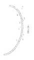
- FIG. 1shows a section of a fuselage section 10 made of composite material.
- the fuselage 10has a curved skin 12 to which stringers 14 and frames 16 are bonded or otherwise secured.
- Securement of the stringers 14 , frames 16 (and other structural members of the fuselage 10 ) to the skin 12has heretofore been a laborious process, and has generally been effectuated in one of three ways.
- the skin 12 , the stringers 14 , and the frames 16may be independently fabricated with composite material.
- Each stringer 14 and frame 16may then be bonded to the skin 12 piece by piece. As can be appreciated, this process may require individual tooling for the securement of each component 14 , 16 , to the skin 12 , which may be fairly time consuming.
- bond mandrelsmay be used to co-cure some of the components 14 , 16 to the skin 12 .
- the mandrelsmay have to be removed after curing, and other parts may have be cured to the skin 12 at locations previously occupied by the mandrels.
- extensive positional toolingmay be used to co-cure the components 14 , 16 , and the skin 12 all at once. Configuration of such extensive tooling may be an arduous task and require much labor.
- U.S. Pat. No. 5,242,523 to Willden et al.discloses a method whereby uncured stiffeners and pre-cured frame members are laid on the surface of the skin.
- a flexible caulis placed between every set of two frame members, and an elongated mandrel is placed under each stiffener.
- the caulsdefine the outer shape of the structure, and the mandrels define the inner shape of the structure.
- the entire structureis placed within a vacuum bag. During this co-curing, the bag presses the frame members against the skin panels, and presses the cauls causing them to press the stiffeners against the skin panel, thus forming the finished structure.
- U.S. Pat. No. 8,220,154 to Cacciaguerradiscloses the use of “shell tooling” for fabricating the fuselage.
- the frames and structural partsare assembled around a chuck resting on a frame structure.
- Shell fixturesare then installed in spaces between the frames, and fastened to the frames by detachable fasteners.
- the shell fixtureshave to be removed after the skin is coupled to the framework.
- a method for eliminating use of extensive positional tooling during construction of a fuselage sectioncomprises the steps of forming a first frame, a second frame, and a third frame by partially curing a composite material.
- Each of the first, second and third frameshave a plurality of locking features molded therein.
- a first stringer, a second stringer, and a third stringeris formed by partially curing the composite material.
- Each of the first, the second, and the third stringershave angled surfaces corresponding to the locking features.
- a solitary bonding tool having a curved bonding surfaceis provided, and each of the first, the second, and the third frames are located in a parallel configuration on the bonding surface.
- a support systemis formed by securing using adhesive the first, the second, and the third frames to each of the first, second, and third stringers such that the angled surfaces of each of the first, second, and third stringers are in contact with one locking feature of each of the first, second, and third frames.
- a skin for the fuselage sectionis provided.
- the skincomprises composite material and is uncured.
- the skinis located with the support system such that an outer surface of the support system is in contact with an inner surface of the skin.
- the skin and the support systemare then fully cured to form the fuselage section.
- a shape of the bonding surfacecorresponds to the shape of an inner surface of the skin.
- a method for making a fuselage sectioncomprises the steps of assembling a support system.
- the support systemcomprises fiber reinforced composite material and includes at least three frames and six stringers.
- the support systemis partially cured via a fast cure process such that the support system attains about eighty percent of its fully cured strength.
- a skin comprising uncured fiber reinforced composite materialis globally positioned such that an inner surface of the skin corresponds to an outer surface of the support system.
- the skin and the support systemare fully cured together.
- the support systemis assembled on a bonding tool having a bonding surface corresponding to an inner surface of the skin.
- a method for constructing a fuselage sectioncomprises the step of forming a plurality of frames by partially curing a composite material.
- Each of the frameshas a plurality of locking features molded therein.
- a plurality of stringersare formed by partially curing the composite material.
- Each stringerhas angled surfaces corresponding to the locking features.
- a bonding tool having a plurality of attachment membersis provided.
- Each attachment memberhas a curved bonding surface with ridges extending partially therethrough.
- Each frameis removably secured to a different attachment member such that at least one of the locking features of each frame is adjacent one ridge.
- a support systemis formed on the tool by securing stringers to the frames such that at least one of the locking features of each frame is adjacent one ridge.
- a skin for the fuselagecomprises uncured composite material.
- the skinis positioned atop the support system.
- the uncured skin and the partially cured support systemare fully cured together.
- a shape of the bonding surface of each attachment membercorresponds to a shape of an inner surface of the skin.
- FIG. 1is a perspective view of a prior art fuselage section
- FIG. 2Ais a perspective view of a frame used in the assembly of a support system, according to an embodiment
- FIG. 2Bis another perspective view of the frame of FIG. 2A ;
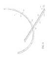
- FIG. 3is a perspective view of a stringer used in the assembly of the support system, according to an embodiment
- FIG. 4shows the stringer of FIG. 3 being secured to a locking feature of the frame
- FIG. 5Ashows the support system being assembled on a female tool, according to an embodiment
- FIG. 5Bis a perspective view of a male tool used to form the support system, according to an embodiment
- FIG. 6is a perspective view of the support system removed from the tool
- FIG. 7shows the support system being globally positioned on a skin of an aircraft
- FIG. 8is a flowchart outlining a method of assembling the fuselage section of FIG. 1 , according to an embodiment.
- Embodiments of the present inventionprovide systems and a method for constructing and assembling a fuselage of an aircraft.
- the systems and methods disclosed hereinmay also be used to fabricate and assemble composite structures for automobiles, boats, wind turbines, et cetera. Unless otherwise noted or as would be inherent, the followings terms when used in the disclosure will have the following meaning.
- Bondingis the assembly of two or more cured or partially cured parts. Bonding may require surface preparation of each faying surface, and additional adhesive.
- Co-bondingis the assembly of two or more parts with at least the faying surfaces being uncured or partially cured and wherein prepreg materials requiring surface preparation can be bonded to cured components.
- the use of adhesive for co-bondingis optional.
- Co-curingis the curing and/or assembly of two or more parts in which at least one of the parts has not previously been cured fully.
- the use of adhesive during co-curingis optional.
- Curingis to toughen or harden material (e.g., thermoset resin formulations) by heat, radiation, chemical additives, et cetera. As used herein, curing is to cure a single component in an autoclave or oven, for example.
- Bond line thicknessThe gap between the bonded surfaces of the two parts.
- Composite materialMaterial made from two or more constituent materials having different physical or chemical properties, which, when combined, produce the composite material having characteristics different from the individual constituent materials.
- PrepregA fibrous material pre-impregnated with a particular synthetic resin and formed into sheets or strips.
- FIG. 1shows a fuselage section 10 made of composite material and having a curved skin 12 .
- the skin 12may have an inner surface 12 I and an outer surface 12 O.
- Stringers 14 and frames 16may be bonded or otherwise secured to the inner surface 12 I of the skin 12 .
- the stringers 14(which may also be referred to as longerons or stiffeners) and frames 16 may form a support system 18 for transferring and absorbing aerodynamic loads acting on the skin 12 .
- the support system 18 as outlined hereincomprises a plurality of stringers 14 and frames 16 . People of skill in the art will appreciate, however, that the support system 18 may include other components (e.g., ribs, spars, et cetera). Further, while the fuselage section 10 depicted in FIG.
- the support system 18may also be referred to herein as the “skeleton structure 18 .”
- FIGS. 2A and 2Bshow frame 16 .
- Frame 16may be curved, and have a top surface 20 T, a bottom surface 22 B, a first side surface 24 S, and a second side surface 26 S.
- a first protruding member 28 Pmay extend outward from the top surface 20 T above the first side surface 24 S (see FIG. 2A ), and be generally parallel to the top surface 20 T.
- a second protruding member 30 Pmay extend outward from the bottom surface 22 B below the second side surface 26 S (see FIG. 2B ), and be generally parallel to the bottom surface 22 B. While not clearly shown in the figures, another protruding member may extend outward from the top surface 20 T above the second side surface 26 S, and yet another protruding member may extend outward from the bottom surface 22 B below the first side surface 24 S.
- Each frame 16may have one or more locking features 32 L.
- the locking features 32 Lmay extend through the bottom surface 22 B, and part of the first side surface 24 S and the second side surface 26 S of the frames 16 .
- the locking features 32 Lmay each include a groove having a first angled surface 34 A, a second angled surface 36 A, and a top surface 38 T that is generally parallel to the top surface 20 T of the frame 16 .
- the locking features 32 L of the frames 16may allow the frames 16 to mate with and be conveniently locked with respect to the stringers 14 .
- Each frame 16may, but need not, be made of composite material (e.g., carbon fibre, glass, et cetera, embedded in plastic, metal, ceramic or another matrix), and may be independently fabricated by conventional means. For example, prepreg may be laid between release films upon a bonding tool and cured in an oven or autoclave at high pressure. Each frame 16 when so formed may be fully cured. Alternatively, each frame 16 may be partially cured such that it is at about 80 to 90 percent of its fully cured strength. People of skill in the art will appreciate that a partially cured frame 16 at about 80 to 90 percent of its fully cured strength is stable and may not be easily deformed or distorted. Embodiments where some or all of the frames 16 are made of metal (e.g., aluminum alloys) are also contemplated.
- metale.g., aluminum alloys
- FIG. 3shows the stringer 14 .
- the stringer 14may have a first side surface 40 S, a second side surface 42 S, a first angled surface 44 A, a second angled surface 46 A, and a top surface 48 T.
- the first angled surface 44 Amay extend from at an angle from the first side surface 40 S.
- the second angled surface 46 Amay extend at an angle from the second side surface 42 S.
- the top surface 48 Tmay extend between and connect the first and second angled surfaces 44 A, 46 A.
- Each stringer 14may, but need not comprise composite material, and may be fabricated individually. Alternatively, the stringers 14 may be made of metal or metal alloys.
- the first and second angled surfaces 44 A, 46 A of the stringer 14may be configured such that the stringer 14 can be snugly mated and locked with respect to the frame 16 .
- the frame 16may be mated with the stringer 14 such that the first and second angled surfaces 44 A, 46 A of the stringer 14 are adjacent and contact the second angled surface 36 A and the first angled surface 34 A of the frame 16 , respectively, and the top surface 38 T of the locking feature 32 L of the frame 16 is adjacent and contacts the top surface 48 T of the stringer 14 .
- the support system 18may be assembled fairly effortlessly. Specifically, as shown in FIG. 5 , a plurality of frames 16 may be laid on a solitary bonding tool 50 T such that one frame 16 is generally parallel to another frame 16 , and a distance between two adjacent frames 16 is generally equal to the distance between at least two other adjacent frames 16 .
- the bonding tool 50 Tmay have a curved bonding surface 51 C that corresponds to the inner surface 12 I of the skin 12 (i.e., a “female” tool), and the support system 18 may be assembled on the curved surface 51 C of the tool 50 T.
- a different toole.g., a male tool as in FIG. 5( b ) discussed further below
- a different toolmay be used to assemble the support system 18 .
- the frames 16may be laid on the curved surface 51 C of the tool 50 T such the bottom surfaces 22 B of the frames 16 are adjacent the curved surface 51 C of the tool 50 T.
- Three frames 16 a , 16 b , and 16 care shown in FIG. 5 ; however, people of skill in the art will appreciate that any number of frames 16 (and any other components) may be placed atop the curved surface 51 C during assembly of the support structure 18 .
- Stringers 14 a - 14 kmay then be passed through some or all of the locking features 32 L of each frame 16 a , 16 b , and 16 c .
- the stringer 14 amay be slid through the locking feature 32 L of the frame 16 a such that the first and second angled surfaces 44 A, 46 A of the stringer 14 a are adjacent and in contact with the second angled surface 36 A and the first angled surface 34 A of the frame 16 A, respectively, and the top surface 38 T of the locking feature 32 L of the frame 16 a is adjacent the top surface 48 T of the stringer 14 .
- the stringer 14 amay then be pushed on the bonding tool 50 T and slid through the locking features 32 L of the frames 14 b and 14 c in the same manner.
- Stringer 14 bmay then be pushed through the locking features 32 L of the frames 16 a , 16 b , and 16 c .
- the processmay be repeated for stringers 14 c - 14 k to assemble the support system 18 .
- the locking features 32 L of the frames 16 a , 16 b , 16 cmay include adhesive, which, when cured, may ensure that the stringers 14 a - 14 k are unable to move relative to the frames 16 a - 16 c once fabrication of the support system 18 is complete.
- no stringers 14may be passed through some of the locking features 32 L of the frames 16 , thus forming exaggerated gaps 33 G between some stringers 14 (e.g., between stringer 14 d and stringer 14 e ).
- the gaps 33 Gmay allow for subsequent placement of windows 51 W (see FIG. 7 ) and other parts.
- the support system 18may be transported as a whole and separated from the bonding tool 50 T (see FIG. 6 ). Because the shape of the curved surface 51 C of the bonding tool 50 T may correspond to the inner surface 12 I of the skin 12 , the shape of an outer surface 18 O of the support system 18 assembled on said tool 50 T may also correspond to the inner surface 12 I of the skin 12 .
- the entire support system 18may then be globally positioned upon the inner surface 12 I of an uncured resin pre-impregnated skin 12 .
- the support system 18may be positioned upon the inner surface 12 I of the skin 12 such that the outer surface 18 O of the support system 18 is adjacent and in contact with the inner surface 12 I of the skin 12 .
- the support system 18which as noted above may be cured or partially cured, and the uncured skin 12 , may now be cured together (e.g., in an autoclave or oven) to form the fuselage section 10 .
- the curing of the support system 18 and the skinmay cause the support system 18 to become permanently secured to the skin 12 .
- FIG. 8shows a method 200 for manufacturing and assembling the fuselage 10 .
- the method 200begins at step 202 , and at step 204 , a plurality of composite material frames 16 , each having locking features 32 L molded therein, may be partially cured such that each frame 16 is at about 80 to 90 percent of its fully cured strength. Alternatively, the frames 16 may be fully cured.
- a plurality of composite material stringers 14each having angled surface 44 A, 46 A corresponding to the locking features 32 L of the frames 16 , may be partially cured such that the frames 16 are at about 80 to 90 percent of their fully cured strength.
- the stringers 14may alternatively be fully cured. People of skill in the art will appreciate that the frames 16 and stringers 14 may be so formed in any order, and that the frames 16 need not be fabricated before the stringers 16 .
- a solitary bonding tool 50 T having a curved surface 51 Cmay be provided.
- the shape of the curved surface 51 C of the tool 50 Tmay generally correspond to the shape of the inner surface 12 I of the skin 12 .
- the frames 16may be laid on the bonding tool 50 T. While not required, the frames 16 may be laid on the curved surface 51 C of the tool 50 T in a parallel configuration for convenience of subsequent assembly.
- uncured adhesivemay be provided adjacent the locking features 32 L of the frames 16 . Alternatively, the adhesive may be provided at the locking features 32 L before the frames 16 are placed on the curved surface 51 C.
- the stringers 14may be slid on the bonding tool 50 T through the locking features 32 L of some or all the frames 16 .
- the adhesivemay be allowed to cure. The cured adhesive may bond the stringers 14 to the frames 16 , thus forming the support system 18 .
- the support system 18may be separated from the bonding tool at step 218 , and if required, conveniently transported to another location for assembly with the skin 12 .
- an uncured prepreg skin 12may be provided.
- the support systemmay be globally positioned on the inner surface 12 I of the uncured skin 12 at step 222 .
- This step 222may require minimal or no tooling, as the outer surface 18 O of the support system 18 is already configured to correspond to the inner surface 12 I of the skin 12 .
- the uncured skin 12along with the partially (or fully) cured support system 18 placed thereon, may then be cured together in an autoclave (or in an oven, or by other conventional means) to form the fuselage section 10 .
- the method 200may then end at step 226 .
- Forming the support system 18 via the solitary bonding tool 50 T, and then co-curing the entire support system 18 with the uncured skin 12 at once according to the method 200may have several advantages over the traditional method of bonding each component 14 , 16 to the skin 12 piece by piece. Specifically, the method 200 , by allowing the entire support system 18 to be laid atop and cured with the skin 12 together, eliminates the extensive and complex tooling that is otherwise required to bond each stringer 14 and frame 16 to the skin 12 individually. The method 200 also eliminates the need for caul sheets which are conventionally used when bonding individual components 14 , 16 to the skin 12 . The method 200 , thus, by utilizing a solitary and simple bonding tool 50 T, saves significant time, labor and material costs as compared to traditional methods of forming the fuselage section 10 .
- the method 200may result in tighter tolerances at both the inner mold line and the outer mold line. Specifically, variability may be imparted when individual components 14 , 16 are bonded to the skin 12 piece by piece, and this variability may result in the production of an inferior or weakened composite fuselage 10 .
- the method 200by utilizing a single bond tool 50 T to form the entire support system 18 together, and by then curing the entire support system 18 with the skin 12 at once, may result in tighter tolerances and less variability.
- the locking features 32 L of the frames 16may further ensure that the frames 16 and stringers 14 are secured to each other uniformly.
- the plies of the skin 12may help minimize any remaining gapping during cure, thus resulting advantageously in a zero bond line on the inner mold line as well as the outer mold line.
- various tolerances of the support system 18may be tested after the support system 18 is assembled on the tool 50 T and before it is secured to the skin 12 . Any defects in the support system 18 , thus, may be remedied where possible before the support system 18 is cured with the skin 12 .
- the strength of the support system 18may also be tested before it is cured with the skin 12 .
- Adhesiveis generally utilized when bonding each component 14 , 16 to the skin 12 piece by piece.
- the method 200may render unnecessary the use of adhesive for bonding the skin 12 to the support system 18 .
- the support system 18may utilize the prepreg of the uncured skin 12 as an adhesive when being cured therewith. The method 200 may thus save additional costs of materials.
- FIG. 5( b )shows a male bonding tool 60 T.
- the male bonding tool 60 Tmay have a plurality of generally semicircular attachment members 62 , each having a front surface 64 F, a rear surface 64 R, and a top surface 64 T.
- Each attachment member 62may be generally parallel to and be spaced apart from an adjacent attachment member 62 .
- a spacing 63 A between two adjacent attachment members 62may be less than a spacing 63 B between two other adjacent attachment members 62 .
- the top surface 64 T of each of the attachment members 62may have indentations or ridges 66 .
- the ridges 66 of one attachment member 62may be in line with and correspond to the ridges 66 in the other attachment members 62 .
- the shape of the top surface 64 T of the attachment members 62may generally correspond to the shape of the inner surface 12 I of the skin 12 .
- the bonding tool 50 Tmay be made of Masonite, ceramic, plastics, metals, metal alloys, composites, or other desirable materials.
- the male bonding tool 60 Tmay be used as an alternative to the female bonding tool 50 T to form the support structure 18 .
- frames 16may first be removably secured (e.g., by clamps or fasteners) to the rear surface 64 R of the attachment members 62 .
- the frames 16may be clamped to the rear surface 64 R of the attachment members 62 such that one of the first side surface 24 S and the second side surface 26 S of the frames 16 is adjacent the rear surface 64 R of the attachment members 62 , and the locking features 32 L of the frames 16 are adjacent the ridges 66 of the attachment members 62 .
- the male bonding tool 60 Tmay have connecting members 67 extending between the attachment members 62 , and the frames 16 may be placed on the connecting members 67 such that the locking features 32 L of the frames 16 are adjacent the ridges 66 of the attachment members 62 .
- the stringers 14may be placed within the locking features 32 L. Specifically, the stringers 14 may be placed within the locking features 32 L of the frames 16 such that the first and second angled surfaces 44 A, 46 A of the stringers 14 are adjacent and in contact with the second angled surface 36 A and the first angled surface 34 A of the frames 16 , respectively, and the top surfaces 38 T of the locking features 32 L of the frames 16 are adjacent the top surfaces 48 T of the stringers 14 .
- the locking features 32 Lmay contain adhesive, which may bond the frames 16 and stringers 14 to each other to form the support system 18 .
- the frames 16may also be removably secured to the front surface 64 F of the attachment members 62 for subsequent securement of the stringers 14 to the frames 16 .
- some of the frames 16may be clamped to the attachment members 62 such that they are adjacent the front surface 64 F of the attachment members 62
- other frames 16may be clamped such that they are adjacent the rear surface 64 R of the attachment members 62 .
- the varying distancese.g., distances 63 A, 63 B
- the support system 18may incorporate other parts (e.g., windows 51 W).
- the support system 18As discussed above, after the support system 18 is assembled using the female tool 50 T, the support system 18 generally has to be transported (or at least inverted) so that the outer surface 18 O of the support system 18 can be secured to the inner surface 12 I of the skin 12 .
- the male tool 61 Tmay render this step unnecessary.
- the outer surface 18 O of the support system 18faces away from the male tool 60 T.
- the uncured skin 12thus, may simply be placed atop the support system 18 such that the inner surface 12 I of the skin 12 is adjacent and in contact with the outer surface 18 O of the support system 18 .
- the uncured skin 12 and the cured or partially cured support system 18may then be cured together to form the fuselage section 10 .
- the support system 18may be cured or partially cured via conventional means, in some embodiments, the support system 18 may be cured or partially cured using a “fast cure” process, or for example, using an internally heated and pressurized systems.
- the fast cure processis described in more detail in concurrently filed co-pending U.S. patent application Ser. No. 13/763,416, filed 8 Feb. 2013, and U.S. patent application Ser. No. 13/763,584, filed 8 Feb. 2013. The disclosure of each is incorporated herein by reference in its entirety.
- Curing of the support system 18 (and other composite structures) via the fast cure processmay be effectuated at a rate of 15 to 20° F. per minute, and the support system 18 may achieve about 80% to 90% of its fully cured strength, stiffness, and service temperature capability within twenty to thirty minutes.
- temperature of each component 14 , 16 of the support system 18may be raised rapidly such that it reaches a predefined threshold, and held at the threshold for a cure (or dwell) time.
- the predefined thresholdmay be, for example, the glass transition temperature (T g ) of the prepreg composite laminate, and is defined as the temperature at which the polymer matrix of the composite material starts cross-linking of the molecules to produce a rigid structure.
- the T g temperaturemay vary depending on properties of the composite material (e.g., its fiber and resin content). In some embodiments, for example, a temperature of about 250° F. may be applied to the prepreg when forming the components 14 , 16 . In other embodiments, a temperature of about 350° F., between 250° F. and 350° F., or below 250° F. may be applied. The cure time may be shorter for composite materials requiring a relatively lower curing temperature.
Landscapes
- Engineering & Computer Science (AREA)
- Mechanical Engineering (AREA)
- Aviation & Aerospace Engineering (AREA)
- Manufacturing & Machinery (AREA)
- Chemical & Material Sciences (AREA)
- Chemical Kinetics & Catalysis (AREA)
- General Chemical & Material Sciences (AREA)
- Transportation (AREA)
- Architecture (AREA)
- Civil Engineering (AREA)
- Structural Engineering (AREA)
- Moulding By Coating Moulds (AREA)
Abstract
Description
Claims (6)
Priority Applications (2)
| Application Number | Priority Date | Filing Date | Title |
|---|---|---|---|
| US13/763,427US9051062B1 (en) | 2012-02-08 | 2013-02-08 | Assembly using skeleton structure |
| US14/518,583US9649820B1 (en) | 2012-02-08 | 2014-10-20 | Assembly using skeleton structure |
Applications Claiming Priority (2)
| Application Number | Priority Date | Filing Date | Title |
|---|---|---|---|
| US201261596644P | 2012-02-08 | 2012-02-08 | |
| US13/763,427US9051062B1 (en) | 2012-02-08 | 2013-02-08 | Assembly using skeleton structure |
Related Child Applications (1)
| Application Number | Title | Priority Date | Filing Date |
|---|---|---|---|
| US14/518,583Continuation-In-PartUS9649820B1 (en) | 2012-02-08 | 2014-10-20 | Assembly using skeleton structure |
Publications (1)
| Publication Number | Publication Date |
|---|---|
| US9051062B1true US9051062B1 (en) | 2015-06-09 |
Family
ID=53267797
Family Applications (1)
| Application Number | Title | Priority Date | Filing Date |
|---|---|---|---|
| US13/763,427Expired - Fee RelatedUS9051062B1 (en) | 2012-02-08 | 2013-02-08 | Assembly using skeleton structure |
Country Status (1)
| Country | Link |
|---|---|
| US (1) | US9051062B1 (en) |
Cited By (9)
| Publication number | Priority date | Publication date | Assignee | Title |
|---|---|---|---|---|
| WO2017183684A1 (en)* | 2016-04-20 | 2017-10-26 | 川崎重工業株式会社 | Aircraft fuselage assembly jig and method for using same |
| WO2017183685A1 (en)* | 2016-04-20 | 2017-10-26 | 川崎重工業株式会社 | Aircraft fuselage assembly jig and method for handling aircraft fuselage panels |
| WO2018109255A1 (en)* | 2016-12-16 | 2018-06-21 | Torres Martinez M | Method for producing reinforced monocoque structures and structure obtained |
| FR3060441A1 (en)* | 2016-12-20 | 2018-06-22 | Deutsches Zentrum Fur Luft- Und Raumfahrt E.V. | COMPONENT STRUCTURE AND METHOD FOR MANUFACTURING THE SAME |
| WO2018170330A1 (en)* | 2017-03-16 | 2018-09-20 | The Boeing Company | Methods of co-bonding a first thermoset composite and a second thermoset composite to define a cured composite part |
| CN114147994A (en)* | 2021-11-24 | 2022-03-08 | 航天特种材料及工艺技术研究所 | A kind of composite material cabin structure integral molding method |
| US11331833B2 (en) | 2017-03-16 | 2022-05-17 | The Boeing Company | Systems and methods of curing a thermoset composite to a desired state of cure |
| US11752708B2 (en) | 2021-09-10 | 2023-09-12 | The Boeing Company | Uncured composite structures, cured composite structures, and methods of curing uncured composite structures |
| US20230356857A1 (en)* | 2022-05-03 | 2023-11-09 | The Boeing Company | Method and Apparatus for the Application of Frame to Fuselage Pull-up Force via Fuselage Skin Waterline Tensioning |
Citations (41)
| Publication number | Priority date | Publication date | Assignee | Title |
|---|---|---|---|---|
| US4740540A (en)* | 1984-06-08 | 1988-04-26 | Dainippon Ink And Chemicals, Inc. | Fiber-reinforced resol-epoxy-amine resin composition molding material and method for producing same |
| US4770929A (en) | 1986-09-02 | 1988-09-13 | Toray Industries, Inc. | Light-weight composite material |
| US4833029A (en) | 1986-12-19 | 1989-05-23 | Hughes Aircraft Company | Honeycomb facesheet material and honeycomb made therewith |
| US5123985A (en) | 1986-09-02 | 1992-06-23 | Patricia Evans | Vacuum bagging apparatus and method including a thermoplastic elastomer film vacuum bag |
| US5223067A (en)* | 1990-02-28 | 1993-06-29 | Fuji Jukogyo Kabushiki Kaisha | Method of fabricating aircraft fuselage structure |
| US5242523A (en) | 1992-05-14 | 1993-09-07 | The Boeing Company | Caul and method for bonding and curing intricate composite structures |
| US5368807A (en) | 1989-12-26 | 1994-11-29 | Mcdonnell Douglas Corporation | Method for vacuum bag molding fiber reinforced resin matrix composites |
| US5448505A (en)* | 1993-11-24 | 1995-09-05 | Tbe Boeing Company | Feed through dimensional measurement system |
| US5562796A (en) | 1994-05-24 | 1996-10-08 | Dorner Mfg. Corp. | Heat press for joining the spliced ends of a conveyor belt |
| US5604010A (en) | 1996-01-11 | 1997-02-18 | Hartz; Dale E. | Composite honeycomb sandwich structure |
| US5707576A (en) | 1994-10-04 | 1998-01-13 | Boeing North American, Inc. | Process for the fabrication of composite hollow crown-stiffened skins and panels |
| US6128998A (en) | 1998-06-12 | 2000-10-10 | Foster Miller, Inc. | Continuous intersecting braided composite structure and method of making same |
| US20020006523A1 (en) | 2000-07-07 | 2002-01-17 | Obeshaw Dale Francis | Structural members containing vibration damping mechanisms and methods for making the same |
| US20020071920A1 (en) | 2000-07-07 | 2002-06-13 | Dale Francis Obeshaw | Contoured composite structural mambers and methods for making the same |
| US6458309B1 (en) | 1998-06-01 | 2002-10-01 | Rohr, Inc. | Method for fabricating an advanced composite aerostructure article having an integral co-cured fly away hollow mandrel |
| US20030082385A1 (en) | 2001-07-13 | 2003-05-01 | Toray Composites (America), Inc. | Quick cure carbon fiber reinforced epoxy resin |
| US6589472B1 (en) | 2000-09-15 | 2003-07-08 | Lockheed Martin Corporation | Method of molding using a thermoplastic conformal mandrel |
| US6613258B1 (en)* | 1997-07-22 | 2003-09-02 | Aerospatiale Societe Nationale Industrielle | Method for making parts in composite material with thermoplastic matrix |
| US20030168555A1 (en) | 2002-02-19 | 2003-09-11 | Alenia Aeronautica S.P.A. | Methods of manufacturing a stiffening element for an aircraft skin panel and a skin panel provided with the stiffening element |
| US20030198775A1 (en) | 2002-04-19 | 2003-10-23 | Roth Arthur J. | Composite structural material and method of making same |
| US20040115299A1 (en) | 2002-12-11 | 2004-06-17 | John Potter | Seal-less reusable vacuum bag |
| US20040175555A1 (en) | 2003-03-04 | 2004-09-09 | Toshimichi Ogisu | Composite material and method of manufacturing the same |
| US6866738B2 (en)* | 2000-04-14 | 2005-03-15 | Honda Giken Kogyo Kabushiki Kaisha | Method for producing intermediate product made of fiber-reinforced composite |
| US20050183818A1 (en) | 2004-02-25 | 2005-08-25 | Zenkner Grant C. | Apparatus and methods for processing composite components using an elastomeric caul |
| US20050183808A1 (en) | 2002-06-26 | 2005-08-25 | Michelin Recherche Et Technique S.A. | Hybrid cables with layers which can be used to reinforce tyres |
| US20060006599A1 (en) | 2004-06-29 | 2006-01-12 | Shahidi Ebrahim G | Seal devices and sealing methods |
| US20060049552A1 (en) | 2004-09-03 | 2006-03-09 | Fish John C | Infusion joining of composite structures |
| US20060254710A1 (en) | 2004-12-07 | 2006-11-16 | Grecon Dimter Holzoptimierung Sud Gmbh & Co. Kg | Gluing Press for Lamella-Shaped Pieces of Wood and Method for Pressing such Pieces of Wood |
| US20080083494A1 (en) | 2006-09-27 | 2008-04-10 | Peter Sander | Method for joining precured or cured stringers to at least one structural component of an aircraft or spacecraft |
| US7410352B2 (en)* | 2005-04-13 | 2008-08-12 | The Boeing Company | Multi-ring system for fuselage barrel formation |
| US20080265093A1 (en) | 2007-04-30 | 2008-10-30 | Airbus Espana, S.L. | Integrated multispar torsion box of composite material |
| US20090020645A1 (en) | 2005-12-20 | 2009-01-22 | Airbus France | Method for Frabricating an Aircraft Fuselage in Composite Material |
| US20090074905A1 (en) | 2007-09-13 | 2009-03-19 | The Boeing Company | Method and apparatus for resin transfer molding composite parts |
| US20090263618A1 (en) | 2008-04-17 | 2009-10-22 | The Boeing Company | Method for producing contoured composite structures and structures produced thereby |
| US20090261199A1 (en) | 2008-04-17 | 2009-10-22 | The Boeing Company | Method for producing contoured composite structures and structures produced thereby |
| US20090283638A1 (en) | 2008-05-16 | 2009-11-19 | Airbus Espana S.L. | Integrated aircraft structure in composite material |
| US20090320398A1 (en) | 2008-06-30 | 2009-12-31 | Gouvea Roberto Paton | Monolithic integrated structural panels especially useful for aircraft structures and methods of making the same |
| US20100098910A1 (en) | 2007-03-12 | 2010-04-22 | Taisei Plas Co., Ltd. | Aluminum alloy composite and method for joining thereof |
| US20100159189A1 (en) | 2008-12-22 | 2010-06-24 | Toyota Boshoku Kabushiki Kaisha | Base fabric for airbag, airbag and method for production of the same |
| US20110045232A1 (en) | 2005-03-31 | 2011-02-24 | The Boeing Company | Composite stiffeners for aerospace vehicles |
| US20110097554A1 (en) | 2008-04-17 | 2011-04-28 | The Boeing Company | Curved composite frames and method of making the same |
- 2013
- 2013-02-08USUS13/763,427patent/US9051062B1/ennot_activeExpired - Fee Related
Patent Citations (42)
| Publication number | Priority date | Publication date | Assignee | Title |
|---|---|---|---|---|
| US4740540A (en)* | 1984-06-08 | 1988-04-26 | Dainippon Ink And Chemicals, Inc. | Fiber-reinforced resol-epoxy-amine resin composition molding material and method for producing same |
| US4770929A (en) | 1986-09-02 | 1988-09-13 | Toray Industries, Inc. | Light-weight composite material |
| US5123985A (en) | 1986-09-02 | 1992-06-23 | Patricia Evans | Vacuum bagging apparatus and method including a thermoplastic elastomer film vacuum bag |
| US4833029A (en) | 1986-12-19 | 1989-05-23 | Hughes Aircraft Company | Honeycomb facesheet material and honeycomb made therewith |
| US5368807A (en) | 1989-12-26 | 1994-11-29 | Mcdonnell Douglas Corporation | Method for vacuum bag molding fiber reinforced resin matrix composites |
| US5223067A (en)* | 1990-02-28 | 1993-06-29 | Fuji Jukogyo Kabushiki Kaisha | Method of fabricating aircraft fuselage structure |
| US5242523A (en) | 1992-05-14 | 1993-09-07 | The Boeing Company | Caul and method for bonding and curing intricate composite structures |
| US5448505A (en)* | 1993-11-24 | 1995-09-05 | Tbe Boeing Company | Feed through dimensional measurement system |
| US5562796A (en) | 1994-05-24 | 1996-10-08 | Dorner Mfg. Corp. | Heat press for joining the spliced ends of a conveyor belt |
| US5707576A (en) | 1994-10-04 | 1998-01-13 | Boeing North American, Inc. | Process for the fabrication of composite hollow crown-stiffened skins and panels |
| US5604010A (en) | 1996-01-11 | 1997-02-18 | Hartz; Dale E. | Composite honeycomb sandwich structure |
| US6613258B1 (en)* | 1997-07-22 | 2003-09-02 | Aerospatiale Societe Nationale Industrielle | Method for making parts in composite material with thermoplastic matrix |
| US6458309B1 (en) | 1998-06-01 | 2002-10-01 | Rohr, Inc. | Method for fabricating an advanced composite aerostructure article having an integral co-cured fly away hollow mandrel |
| US6632502B1 (en) | 1998-06-01 | 2003-10-14 | Rohr, Inc. | Method for fabricating an advanced composite aerostructure article having an integral co-cured fly away hollow mandrel |
| US6128998A (en) | 1998-06-12 | 2000-10-10 | Foster Miller, Inc. | Continuous intersecting braided composite structure and method of making same |
| US6866738B2 (en)* | 2000-04-14 | 2005-03-15 | Honda Giken Kogyo Kabushiki Kaisha | Method for producing intermediate product made of fiber-reinforced composite |
| US20020006523A1 (en) | 2000-07-07 | 2002-01-17 | Obeshaw Dale Francis | Structural members containing vibration damping mechanisms and methods for making the same |
| US20020071920A1 (en) | 2000-07-07 | 2002-06-13 | Dale Francis Obeshaw | Contoured composite structural mambers and methods for making the same |
| US6589472B1 (en) | 2000-09-15 | 2003-07-08 | Lockheed Martin Corporation | Method of molding using a thermoplastic conformal mandrel |
| US20030082385A1 (en) | 2001-07-13 | 2003-05-01 | Toray Composites (America), Inc. | Quick cure carbon fiber reinforced epoxy resin |
| US20030168555A1 (en) | 2002-02-19 | 2003-09-11 | Alenia Aeronautica S.P.A. | Methods of manufacturing a stiffening element for an aircraft skin panel and a skin panel provided with the stiffening element |
| US20030198775A1 (en) | 2002-04-19 | 2003-10-23 | Roth Arthur J. | Composite structural material and method of making same |
| US20050183808A1 (en) | 2002-06-26 | 2005-08-25 | Michelin Recherche Et Technique S.A. | Hybrid cables with layers which can be used to reinforce tyres |
| US20040115299A1 (en) | 2002-12-11 | 2004-06-17 | John Potter | Seal-less reusable vacuum bag |
| US20040175555A1 (en) | 2003-03-04 | 2004-09-09 | Toshimichi Ogisu | Composite material and method of manufacturing the same |
| US20050183818A1 (en) | 2004-02-25 | 2005-08-25 | Zenkner Grant C. | Apparatus and methods for processing composite components using an elastomeric caul |
| US20060006599A1 (en) | 2004-06-29 | 2006-01-12 | Shahidi Ebrahim G | Seal devices and sealing methods |
| US20060049552A1 (en) | 2004-09-03 | 2006-03-09 | Fish John C | Infusion joining of composite structures |
| US20060254710A1 (en) | 2004-12-07 | 2006-11-16 | Grecon Dimter Holzoptimierung Sud Gmbh & Co. Kg | Gluing Press for Lamella-Shaped Pieces of Wood and Method for Pressing such Pieces of Wood |
| US20110045232A1 (en) | 2005-03-31 | 2011-02-24 | The Boeing Company | Composite stiffeners for aerospace vehicles |
| US7410352B2 (en)* | 2005-04-13 | 2008-08-12 | The Boeing Company | Multi-ring system for fuselage barrel formation |
| US20090020645A1 (en) | 2005-12-20 | 2009-01-22 | Airbus France | Method for Frabricating an Aircraft Fuselage in Composite Material |
| US20080083494A1 (en) | 2006-09-27 | 2008-04-10 | Peter Sander | Method for joining precured or cured stringers to at least one structural component of an aircraft or spacecraft |
| US20100098910A1 (en) | 2007-03-12 | 2010-04-22 | Taisei Plas Co., Ltd. | Aluminum alloy composite and method for joining thereof |
| US20080265093A1 (en) | 2007-04-30 | 2008-10-30 | Airbus Espana, S.L. | Integrated multispar torsion box of composite material |
| US20090074905A1 (en) | 2007-09-13 | 2009-03-19 | The Boeing Company | Method and apparatus for resin transfer molding composite parts |
| US20090263618A1 (en) | 2008-04-17 | 2009-10-22 | The Boeing Company | Method for producing contoured composite structures and structures produced thereby |
| US20090261199A1 (en) | 2008-04-17 | 2009-10-22 | The Boeing Company | Method for producing contoured composite structures and structures produced thereby |
| US20110097554A1 (en) | 2008-04-17 | 2011-04-28 | The Boeing Company | Curved composite frames and method of making the same |
| US20090283638A1 (en) | 2008-05-16 | 2009-11-19 | Airbus Espana S.L. | Integrated aircraft structure in composite material |
| US20090320398A1 (en) | 2008-06-30 | 2009-12-31 | Gouvea Roberto Paton | Monolithic integrated structural panels especially useful for aircraft structures and methods of making the same |
| US20100159189A1 (en) | 2008-12-22 | 2010-06-24 | Toyota Boshoku Kabushiki Kaisha | Base fabric for airbag, airbag and method for production of the same |
Non-Patent Citations (6)
| Title |
|---|
| Notice of Allowance issued in related U.S. Appl. No. 12/779,706 dated Jan. 26, 2012, 9 pages. |
| Notice of Allowance issued in related U.S. Appl. No. 12/829,234 dated Jan. 19, 2013, 15 pages. |
| Office Action in related U.S. Appl. No. 12/779,706 dated Aug. 1, 2011, 18 pages. |
| Office Action in related U.S. Appl. No. 12/829,234 dated Jan. 3, 2011, 10 pages. |
| Office Action in related U.S. Appl. No. 12/829,234 dated Mar. 31, 2011, 13 pages. |
| Response to Office Action in related U.S. Appl. No. 12/829,234 dated Mar. 18, 2011, 10 pages. |
Cited By (20)
| Publication number | Priority date | Publication date | Assignee | Title |
|---|---|---|---|---|
| US11260993B2 (en) | 2016-04-20 | 2022-03-01 | Kawasaki Jukogyo Kabushiki Kaisha | Aircraft fuselage assembling jig and method of using the same |
| JP2017193241A (en)* | 2016-04-20 | 2017-10-26 | 川崎重工業株式会社 | Aircraft fuselage assembly jig and method for using the same |
| WO2017183685A1 (en)* | 2016-04-20 | 2017-10-26 | 川崎重工業株式会社 | Aircraft fuselage assembly jig and method for handling aircraft fuselage panels |
| US11345485B2 (en) | 2016-04-20 | 2022-05-31 | Kawasaki Jukogyo Kabushiki Kaisha | Aircraft fuselage assembling jig and method of handling aircraft fuselage panel |
| WO2017183684A1 (en)* | 2016-04-20 | 2017-10-26 | 川崎重工業株式会社 | Aircraft fuselage assembly jig and method for using same |
| WO2018109255A1 (en)* | 2016-12-16 | 2018-06-21 | Torres Martinez M | Method for producing reinforced monocoque structures and structure obtained |
| US11479333B2 (en)* | 2016-12-16 | 2022-10-25 | Manuel Torres Martinez | Method for manufacturing a one-piece reinforced structure and obtained structure |
| FR3060441A1 (en)* | 2016-12-20 | 2018-06-22 | Deutsches Zentrum Fur Luft- Und Raumfahrt E.V. | COMPONENT STRUCTURE AND METHOD FOR MANUFACTURING THE SAME |
| CN110167745A (en)* | 2017-03-16 | 2019-08-23 | 波音公司 | It is glued the first same with thermosetting compound material and the second same with thermosetting compound material altogether to define the method for solidifying composite material component |
| CN110167745B (en)* | 2017-03-16 | 2021-11-02 | 波音公司 | Method of co-bonding a first thermoset composite material and a second thermoset composite material to define a cured composite part |
| US11247409B2 (en) | 2017-03-16 | 2022-02-15 | The Boeing Company | Methods of co-bonding a first thermoset composite and a second thermoset composite to define a cured composite part |
| WO2018170330A1 (en)* | 2017-03-16 | 2018-09-20 | The Boeing Company | Methods of co-bonding a first thermoset composite and a second thermoset composite to define a cured composite part |
| US11331833B2 (en) | 2017-03-16 | 2022-05-17 | The Boeing Company | Systems and methods of curing a thermoset composite to a desired state of cure |
| US11752708B2 (en) | 2021-09-10 | 2023-09-12 | The Boeing Company | Uncured composite structures, cured composite structures, and methods of curing uncured composite structures |
| CN114147994B (en)* | 2021-11-24 | 2023-05-05 | 航天特种材料及工艺技术研究所 | Integral forming method for composite cabin structure |
| CN114147994A (en)* | 2021-11-24 | 2022-03-08 | 航天特种材料及工艺技术研究所 | A kind of composite material cabin structure integral molding method |
| US20230356857A1 (en)* | 2022-05-03 | 2023-11-09 | The Boeing Company | Method and Apparatus for the Application of Frame to Fuselage Pull-up Force via Fuselage Skin Waterline Tensioning |
| US11866201B2 (en)* | 2022-05-03 | 2024-01-09 | The Boeing Company | Method and apparatus for the application of frame to fuselage pull-up force via fuselage skin waterline tensioning |
| US20240101277A1 (en)* | 2022-05-03 | 2024-03-28 | The Boeing Company | Method and Apparatus for the Application of Frame to Fuselage Pull-up Force via Fuselage Skin Waterline Tensioning |
| US12337996B2 (en)* | 2022-05-03 | 2025-06-24 | The Boeing Company | Method and apparatus for the application of frame to fuselage pull-up force via fuselage skin waterline tensioning |
Similar Documents
| Publication | Publication Date | Title |
|---|---|---|
| US9051062B1 (en) | Assembly using skeleton structure | |
| US9649820B1 (en) | Assembly using skeleton structure | |
| JP4960318B2 (en) | Method and apparatus for minimizing misalignments appearing on the surface of composite parts | |
| AU2013254936B2 (en) | Multi-box wing spar and skin | |
| US9669581B2 (en) | Method for manufacturing an aeronautical torsion box, torsion box and tool for manufacturing an aeronautical torsion box | |
| US8834668B2 (en) | Staged cocuring of composite structures | |
| US8043554B2 (en) | Manufacturing process using bladderless mold line conformal hat stringer | |
| EP2318466B1 (en) | Method for manufacturing a composite structure and intermediate composite structure | |
| US7097731B2 (en) | Method of manufacturing a hollow section, grid stiffened panel | |
| EP3088152B1 (en) | Method for manufacturing composite parts and form | |
| US20060231682A1 (en) | Multi-ring system for fuselage barrel formation | |
| US10005267B1 (en) | Formation of complex composite structures using laminate templates | |
| CA2858829A1 (en) | An aircraft structure with structural non-fiber reinforcing bonding resin layer | |
| US8580170B2 (en) | Process for producing a substantially shell-shaped component | |
| US10744724B2 (en) | Composite aircraft manufacturing tooling and methods using articulating mandrels | |
| US20180186478A1 (en) | Integrated ablative heat shield | |
| CN110757838A (en) | Composite material wing and forming and assembling integrated forming method | |
| US20070102839A1 (en) | Method to control thickness in composite parts cured on closed angle tool | |
| CN110712324B (en) | A composite material wing forming and assembling integrated mold | |
| US20160023407A1 (en) | Two Piece Mandrel Manufacturing System | |
| US20170210053A1 (en) | Composite structures with stiffeners and method of making the same |
Legal Events
| Date | Code | Title | Description |
|---|---|---|---|
| AS | Assignment | Owner name:CESSNA AIRCRAFT COMPANY, KANSAS Free format text:ASSIGNMENT OF ASSIGNORS INTEREST;ASSIGNORS:BOONE, RICHARD;DE PUTTER, BENJAMIN;SIGNING DATES FROM 20130430 TO 20130522;REEL/FRAME:030766/0186 | |
| AS | Assignment | Owner name:TEXTRON INNOVATIONS, INC., RHODE ISLAND Free format text:ASSIGNMENT OF ASSIGNORS INTEREST;ASSIGNOR:CESSNA AIRCRAFT RHODE ISLAND;REEL/FRAME:033976/0743 Effective date:20140401 Owner name:CESSNA AIRCRAFT RHODE ISLAND, RHODE ISLAND Free format text:ASSIGNMENT OF ASSIGNORS INTEREST;ASSIGNOR:CESSNA AIRCRAFT COMPANY;REEL/FRAME:033976/0736 Effective date:20140401 | |
| STCF | Information on status: patent grant | Free format text:PATENTED CASE | |
| FEPP | Fee payment procedure | Free format text:MAINTENANCE FEE REMINDER MAILED (ORIGINAL EVENT CODE: REM.); ENTITY STATUS OF PATENT OWNER: LARGE ENTITY | |
| LAPS | Lapse for failure to pay maintenance fees | Free format text:PATENT EXPIRED FOR FAILURE TO PAY MAINTENANCE FEES (ORIGINAL EVENT CODE: EXP.); ENTITY STATUS OF PATENT OWNER: LARGE ENTITY | |
| STCH | Information on status: patent discontinuation | Free format text:PATENT EXPIRED DUE TO NONPAYMENT OF MAINTENANCE FEES UNDER 37 CFR 1.362 | |
| FP | Lapsed due to failure to pay maintenance fee | Effective date:20190609 |