US9050692B2 - Method and apparatus for radome and reflector dish interconnection - Google Patents
Method and apparatus for radome and reflector dish interconnectionDownload PDFInfo
- Publication number
- US9050692B2 US9050692B2US13/279,415US201113279415AUS9050692B2US 9050692 B2US9050692 B2US 9050692B2US 201113279415 AUS201113279415 AUS 201113279415AUS 9050692 B2US9050692 B2US 9050692B2
- Authority
- US
- United States
- Prior art keywords
- periphery
- slot
- link member
- radome
- channel portions
- Prior art date
- Legal status (The legal status is an assumption and is not a legal conclusion. Google has not performed a legal analysis and makes no representation as to the accuracy of the status listed.)
- Expired - Fee Related, expires
Links
Images


Classifications
- H—ELECTRICITY
- H01—ELECTRIC ELEMENTS
- H01Q—ANTENNAS, i.e. RADIO AERIALS
- H01Q1/00—Details of, or arrangements associated with, antennas
- H01Q1/42—Housings not intimately mechanically associated with radiating elements, e.g. radome
- B—PERFORMING OPERATIONS; TRANSPORTING
- B23—MACHINE TOOLS; METAL-WORKING NOT OTHERWISE PROVIDED FOR
- B23P—METAL-WORKING NOT OTHERWISE PROVIDED FOR; COMBINED OPERATIONS; UNIVERSAL MACHINE TOOLS
- B23P11/00—Connecting or disconnecting metal parts or objects by metal-working techniques not otherwise provided for
- B23P11/005—Connecting or disconnecting metal parts or objects by metal-working techniques not otherwise provided for by expanding or crimping
- H—ELECTRICITY
- H01—ELECTRIC ELEMENTS
- H01Q—ANTENNAS, i.e. RADIO AERIALS
- H01Q1/00—Details of, or arrangements associated with, antennas
- H01Q1/12—Supports; Mounting means
- H—ELECTRICITY
- H01—ELECTRIC ELEMENTS
- H01Q—ANTENNAS, i.e. RADIO AERIALS
- H01Q15/00—Devices for reflection, refraction, diffraction or polarisation of waves radiated from an antenna, e.g. quasi-optical devices
- H01Q15/14—Reflecting surfaces; Equivalent structures
- H01Q15/16—Reflecting surfaces; Equivalent structures curved in two dimensions, e.g. paraboloidal
- H—ELECTRICITY
- H01—ELECTRIC ELEMENTS
- H01Q—ANTENNAS, i.e. RADIO AERIALS
- H01Q19/00—Combinations of primary active antenna elements and units with secondary devices, e.g. with quasi-optical devices, for giving the antenna a desired directional characteristic
- H01Q19/10—Combinations of primary active antenna elements and units with secondary devices, e.g. with quasi-optical devices, for giving the antenna a desired directional characteristic using reflecting surfaces
- H01Q19/12—Combinations of primary active antenna elements and units with secondary devices, e.g. with quasi-optical devices, for giving the antenna a desired directional characteristic using reflecting surfaces wherein the surfaces are concave
- Y—GENERAL TAGGING OF NEW TECHNOLOGICAL DEVELOPMENTS; GENERAL TAGGING OF CROSS-SECTIONAL TECHNOLOGIES SPANNING OVER SEVERAL SECTIONS OF THE IPC; TECHNICAL SUBJECTS COVERED BY FORMER USPC CROSS-REFERENCE ART COLLECTIONS [XRACs] AND DIGESTS
- Y10—TECHNICAL SUBJECTS COVERED BY FORMER USPC
- Y10T—TECHNICAL SUBJECTS COVERED BY FORMER US CLASSIFICATION
- Y10T29/00—Metal working
- Y10T29/49—Method of mechanical manufacture
- Y10T29/49826—Assembling or joining
- Y10T29/49908—Joining by deforming
- Y—GENERAL TAGGING OF NEW TECHNOLOGICAL DEVELOPMENTS; GENERAL TAGGING OF CROSS-SECTIONAL TECHNOLOGIES SPANNING OVER SEVERAL SECTIONS OF THE IPC; TECHNICAL SUBJECTS COVERED BY FORMER USPC CROSS-REFERENCE ART COLLECTIONS [XRACs] AND DIGESTS
- Y10—TECHNICAL SUBJECTS COVERED BY FORMER USPC
- Y10T—TECHNICAL SUBJECTS COVERED BY FORMER US CLASSIFICATION
- Y10T403/00—Joints and connections
- Y10T403/49—Member deformed in situ
Definitions
- This inventionrelates to microwave reflector antennas. More particularly, the invention relates to a cost-efficient radome bandclamp-type interconnection for retaining a radome upon the periphery of the reflector dish of a microwave reflector antenna.
- the open end of a reflector antennais typically enclosed by a radome coupled to the distal end (the open end) of the reflector dish.
- the radomeprovides environmental protection and improves wind load characteristics of the antenna. Because reflector antennas are often mounted in remote locations, such as high atop radio towers, a radome failure may incur significant repair/replacement expense.
- a band clampmay be applied to retain the radome upon the reflector dish periphery via a removable closure means, such as a nut and bolt.
- a removable closure meanssuch as a nut and bolt.
- nut and bolt closuresmay loosen with time, increase the total number of discrete components and/or require additional threading/tightening assembly steps.
- the radomemay be retained via an integral connection means of the radome and reflector dish periphery, such as a plurality of tabs that mate with corresponding slots or the like.
- the radome and reflector dishmust be each manufactured with the specific connection means applied to both elements, limiting interchangeability and/or replacement. Competition in the reflector antenna market has focused attention on improving electrical performance and minimization of overall manufacturing, inventory, distribution, installation and maintenance costs. Therefore, it is an object of the invention to provide a band clamp interconnection that overcomes deficiencies in the prior art.
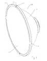
- FIG. 1is a schematic isometric angled front view of an exemplary radome to reflector dish interconnection.
- FIG. 2is a schematic close-up isometric back view of the channel portion ends and link member of FIG. 1 , prior to application of a crimp, radome and reflector dish removed for clarity.
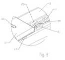
- FIG. 3is a schematic isometric view of FIG. 2 , after application of the crimp.
- FIG. 4is a schematic cross section close-up view of the interconnection, taken along line A-A of FIG. 5 .
- FIG. 5is a schematic cross section view looking into the end of one of the channel sections of FIG. 3 .
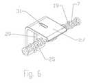
- FIG. 6is a schematic isometric view of an alternative embodiment link member.
- FIG. 7is a schematic isometric view of the link member of FIG. 6 , installed upon the ends of channel portions, prior to crimping.
- FIG. 8is a schematic isometric close-up view of the link member and channel portions of FIG. 7 , after crimping.
- a radome 1is retained on reflector dish 3 via a permanent band clamp type interconnection that may be cost efficiently formed by crimping a plurality of curved channel portions 5 end to end around a shared link member 7 , for example as shown in FIG. 1 .
- a reliable permanent interconnectionmay be cost efficiently formed from a minimum number of simplified parts, which may enable significant materials, manufacturing and/or installation efficiencies.
- the channel portions 5are provided with an open periphery slot 9 and an open retention slot 11 .
- the periphery slot 9is dimensioned to receive the periphery of the radome 1 and the periphery of the reflector dish 3 seated upon one another.
- the channel portions 5are arranged end-to-end adjacent to one another, encircling the periphery of the radome 1 and the periphery of the reflector dish 3 seated within the periphery slot 9 .
- a gap 17may be provided between each channel portions 5 are arranged end-to-end adjacent to one another.
- the retention slot 11may be oriented normal to the periphery slot and on a back side 13 of the channel portions 5 . That is, the generally U-shaped periphery and retention slots 9 , 11 are each open to a direction generally 90 degrees from the other. Thereby the retention slot 11 may be easily accessed for crimping but the retention slot 11 remains generally out of view from the front of the assembled reflector antenna 15 .
- the retention slot 11may be oriented 180 degrees from the periphery slot 9 , that is, on outer diameters of the channel portions 5 , for example as shown in FIGS. 7 and 8 . Thereby, the retention slot 11 may operate as an additional choke for any surface currents that may spill over from the RF signals present in the reflector antenna 15 during operation, thus improving a signal pattern of the reflector antenna 15 .
- the channel portions 5may be cost efficiently manufactured, for example, by extrusion of metal such as aluminum and/or aluminum alloy.
- the plurality of channel portions 5is demonstrated here as two channel portions 5 interconnected via two link members. However, one skilled in the art will appreciate that the number of channel portions 5 may be increased by adding additional link members 7 between each of the additional adjacent channel portions 5 as they encircle the periphery of the radome 1 and reflector dish 3 . Use of additional channel portions 5 may provide, for example, simplified channel portion manufacture and/or in-process part storage/transport.
- a link member 7is seated within the retention slot 11 at an end of each adjacent channel portion 5 and the retention slot 11 is crimped upon the link member 7 , for example as shown on FIGS. 3 , 5 and 8 .
- the gap 17may be left between the channel portions 5 to facilitate draining of moisture from the periphery and/or retention channels 9 , 11 and/or accommodate dimensional variances of the radome 1 , reflector dish 5 and/or channel portions 5 during manufacture and/or assembly.
- the link member 7may be provided with at least one retention trough 19 .
- the retention trough 19may be formed as any aperture and/or protrusion of the link member 7 which the sidewalls of the retention slot 11 can deform into/upon and/or which will cut into and grip the retention slot 11 sidewalls during the application of the crimp 21 .
- the retention trough 11may be formed, for example, as a helical thread 23 along the outer diameter of the link member 7 , such as available on metal threaded rod. To cost efficiently form link members 7 of this type, bulk lengths of threaded rod may be cut into short portions.
- the retention troughs 19may be formed as a depression 25 or other cavity, for example by injection molding the link member 7 from a polymer material.
- Link member fabrication by injection moldingmay also enable the cost efficient addition of further features to the link member 7 .
- the link member 7may be formed with a gap cover 27 extending along a portion of an outer diameter of the adjacent channel portions 5 , covering the gap 17 there between.
- the gap cover 27may also extend to cover a front side of the channel portion 5 .
- the gap cover 27may include a seat shoulder 29 that the ends of the adjacent channel portions 5 seat against prior to interconnection.
- the gap cover 27may operate as an aid to aligning the channel portions 5 during initial assembly prior to crimping, as a protective cover for sharp edges of the channel portion 5 ends, as a cosmetic flair for the reflector antenna and/or to reduce chances for environmental fouling of the gap 17 . Where moisture draining is a concern, the gap cover 27 may be formed with a weep hole 31 through the seat shoulder 29 , as best shown in FIG. 7 .
- the channel portions 5are seated upon the periphery of the radome 1 and the reflector dish 3 , within the periphery slot 9 .
- the channel portions 5are arranged end-to-end adjacent to one another encircling the periphery (but for the desired gap 17 ) of the radome 1 and reflector dish 3 .
- a link member 7is seated within the retention slot at the ends of each adjacent channel portion 5 and the retention slot 11 is crimped proximate the end of each of the adjacent channel portions 5 upon the link member 7 .
- the crimpingwill permanently apply a desired level of tension to the resulting interconnection; for example, it may bias a turnback region 33 of the periphery slot sidewall against the back side of the reflector dish 3 to reduce any RF leakage that may otherwise arise between these surfaces.
- the crimp 21 appliedmay be along the extent of the link member 7 , driving the retention slot 11 sidewalls against the selected retention trough 19 formed, for example as the helical thread 23 such that the helical thread 23 cuts into the sidewalls as shown in FIG. 4 .
- the crimp 21may be dimensioned to key within an enlarged retention trough 19 , for example a depression 25 as shown in FIG. 8 . Thereby, retention via the crimping may be realized on both metal materials which cut into the retention slot 11 sidewalls or with respect to polymer materials which would otherwise deform rather than cut the sidewalls.
- the interconnectionmay be formed upon a longitudinally uniform cross-section of extruded material, without any secondary attachment of fittings, closures or other multi-element types of closures, the interconnection fabrication and installation has been simplified, which may reduce material, fabrication and installation costs.
- the interconnectionhas minimal external dimensions, resulting in a streamlined and uniform interconnection with minimal surface irregularities.
- the gap 17accommodates dimensional and/or tolerance variations that remove prior requirements for accurate placement of components during assembly and/or multiple alignment features with corresponding high tolerance manufacturing of the individual assembly components.
- the interconnectionenables cost effective use of aluminum material as the band in close contact with, for example, an aluminum material reflector dish, reducing the need to address dissimilar metal and/or galvanic corrosion concerns along the mating surfaces and/or the prior practice of utilizing a more expensive material for the band such as stainless steel.
Landscapes
- Physics & Mathematics (AREA)
- Electromagnetism (AREA)
- Engineering & Computer Science (AREA)
- Mechanical Engineering (AREA)
- Details Of Aerials (AREA)
- Aerials With Secondary Devices (AREA)
Abstract
Description
| Table of Parts |
| 1 | radome |
| 3 | |
| 5 | |
| 7 | |
| 9 | |
| 11 | |
| 13 | back |
| 15 | |
| 17 | |
| 19 | |
| 21 | |
| 23 | |
| 25 | |
| 27 | |
| 29 | |
| 31 | weep |
| 33 | turnback |
Claims (8)
Priority Applications (5)
| Application Number | Priority Date | Filing Date | Title |
|---|---|---|---|
| US13/279,415US9050692B2 (en) | 2011-10-24 | 2011-10-24 | Method and apparatus for radome and reflector dish interconnection |
| EP12844119.3AEP2771945A4 (en) | 2011-10-24 | 2012-09-02 | Method and apparatus for radome and reflector dish interconnection |
| PCT/IB2012/054527WO2013061176A1 (en) | 2011-10-24 | 2012-09-02 | Method and apparatus for radome and reflector dish interconnection |
| CN201280050598.4ACN103875123B (en) | 2011-10-24 | 2012-09-02 | For the method and apparatus of radome and reflector disks cross tie part |
| US14/704,151US20150236406A1 (en) | 2011-10-24 | 2015-05-05 | Method for Radome and Reflector Dish Interconnection |
Applications Claiming Priority (1)
| Application Number | Priority Date | Filing Date | Title |
|---|---|---|---|
| US13/279,415US9050692B2 (en) | 2011-10-24 | 2011-10-24 | Method and apparatus for radome and reflector dish interconnection |
Related Child Applications (1)
| Application Number | Title | Priority Date | Filing Date |
|---|---|---|---|
| US14/704,151DivisionUS20150236406A1 (en) | 2011-10-24 | 2015-05-05 | Method for Radome and Reflector Dish Interconnection |
Publications (2)
| Publication Number | Publication Date |
|---|---|
| US20130099991A1 US20130099991A1 (en) | 2013-04-25 |
| US9050692B2true US9050692B2 (en) | 2015-06-09 |
Family
ID=48135525
Family Applications (2)
| Application Number | Title | Priority Date | Filing Date |
|---|---|---|---|
| US13/279,415Expired - Fee RelatedUS9050692B2 (en) | 2011-10-24 | 2011-10-24 | Method and apparatus for radome and reflector dish interconnection |
| US14/704,151AbandonedUS20150236406A1 (en) | 2011-10-24 | 2015-05-05 | Method for Radome and Reflector Dish Interconnection |
Family Applications After (1)
| Application Number | Title | Priority Date | Filing Date |
|---|---|---|---|
| US14/704,151AbandonedUS20150236406A1 (en) | 2011-10-24 | 2015-05-05 | Method for Radome and Reflector Dish Interconnection |
Country Status (4)
| Country | Link |
|---|---|
| US (2) | US9050692B2 (en) |
| EP (1) | EP2771945A4 (en) |
| CN (1) | CN103875123B (en) |
| WO (1) | WO2013061176A1 (en) |
Cited By (2)
| Publication number | Priority date | Publication date | Assignee | Title |
|---|---|---|---|---|
| US20150249281A1 (en)* | 2012-09-24 | 2015-09-03 | Alcatel Lucent | Joining device for fastening a radome onto an antenna reflector |
| US10158169B1 (en) | 2017-08-01 | 2018-12-18 | Winegard Company | Mobile antenna system |
Families Citing this family (10)
| Publication number | Priority date | Publication date | Assignee | Title |
|---|---|---|---|---|
| USD744985S1 (en)* | 2013-02-08 | 2015-12-08 | Ubiquiti Networks, Inc. | Radio system |
| EP2883276B1 (en) | 2013-06-27 | 2019-05-22 | CommScope Technologies LLC | Foldable radome |
| US9577323B2 (en) | 2014-03-07 | 2017-02-21 | Commscope Technologies Llc | Radome—reflector assembly mechanism |
| ES2868348T3 (en)* | 2014-10-14 | 2021-10-21 | Ubiquiti Inc | Signal isolation covers and reflectors for antenna |
| EP3298655A4 (en)* | 2015-05-21 | 2019-01-16 | Commscope Technologies LLC | Segmented antenna radome |
| USD816645S1 (en)* | 2015-08-24 | 2018-05-01 | Ubiquiti Networks, Inc. | Shrouded microwave antenna reflector |
| EP3516735A4 (en)* | 2016-09-23 | 2020-04-22 | Commscope Technologies LLC | Antenna cover and methods of retention |
| JP7097793B2 (en)* | 2018-10-17 | 2022-07-08 | 株式会社Kelk | Detection device |
| DE102019109286A1 (en)* | 2019-04-09 | 2020-10-15 | Vibracoustic Ag | Retaining ring, location and method of assembling the retaining ring |
| CN113478182B (en)* | 2021-07-15 | 2023-05-23 | 贵州航天电子科技有限公司 | Post-welding processing method for telemetry antenna |
Citations (36)
| Publication number | Priority date | Publication date | Assignee | Title |
|---|---|---|---|---|
| US2703159A (en) | 1953-02-05 | 1955-03-01 | Vincent Van Fleet | Window sash |
| US2717667A (en) | 1953-10-01 | 1955-09-13 | Joseph C Bancroft | Window frame construction |
| US2989788A (en) | 1959-03-09 | 1961-06-27 | Kessler Milton | Corner key for screen frames and the like |
| US3321885A (en) | 1965-06-21 | 1967-05-30 | Clifford W Pratt | Screen frame and corner construction |
| US3351947A (en)* | 1965-02-17 | 1967-11-07 | Mark Products Company | Shrouded parabolic antenna structure |
| US3606419A (en) | 1969-06-18 | 1971-09-20 | Homeshield Ind Inc | Molded plastic corner lock |
| US3687512A (en) | 1967-10-16 | 1972-08-29 | Leslie W L Alston | Drawers for furniture |
| US3782054A (en) | 1971-09-15 | 1974-01-01 | Capitol Prod Corp | Corner angle for windows |
| US3784043A (en) | 1968-11-29 | 1974-01-08 | M Presnick | Lightweight collapsible structures |
| US3786612A (en) | 1970-11-17 | 1974-01-22 | W Baker | Angle connectors for modular beam structures |
| US3866380A (en) | 1974-04-02 | 1975-02-18 | Warren Ind | Connector for window spacer assembly |
| US3973371A (en) | 1974-10-21 | 1976-08-10 | Heller Stephen M | Furniture and wall structural system |
| US4042288A (en) | 1972-12-08 | 1977-08-16 | L. B. (Plastics) Limited | Extruded plastic panel drawers |
| US4090799A (en) | 1975-10-21 | 1978-05-23 | Color-Plast S.P.A. | Miter joint for hollow plastic frame members |
| US4099815A (en) | 1975-05-30 | 1978-07-11 | Swish Products Limited | Structural elements |
| US4136496A (en) | 1978-01-28 | 1979-01-30 | Radway Plastics Limited | Structural elements for sub-frames |
| US4348127A (en) | 1981-07-24 | 1982-09-07 | Hays Jr George O | Connector for extruded sections such as picture frame members |
| US4368584A (en) | 1980-12-02 | 1983-01-18 | Logan Graphic Products, Inc. | Picture frame assembly components |
| US4453855A (en) | 1981-08-03 | 1984-06-12 | Thermetic Glass, Inc. | Corner construction for spacer used in multi-pane windows |
| US4477990A (en) | 1982-06-08 | 1984-10-23 | William Sornborger | Picture frame |
| US4570406A (en) | 1983-12-12 | 1986-02-18 | Acorn Building Components, Inc. | Screen frame corner connector key |
| US4662092A (en) | 1985-08-01 | 1987-05-05 | Kim Han K | Picture frame construction |
| US4856230A (en) | 1988-05-31 | 1989-08-15 | Slocomb Industries | Ultra sound welded window frames |
| US4918459A (en) | 1989-02-27 | 1990-04-17 | Teso John S De | Apparatus for protecting antennas |
| US4930284A (en)* | 1987-12-21 | 1990-06-05 | Falco Gene A | Masonry anchor |
| US4987709A (en) | 1989-03-08 | 1991-01-29 | Repla Limited | Frame construction system |
| US5079860A (en) | 1990-02-20 | 1992-01-14 | Nugent Rick B | Frame for decorative objects |
| US5907310A (en) | 1996-06-12 | 1999-05-25 | Alcatel | Device for covering the aperture of an antenna |
| US6137449A (en) | 1996-09-26 | 2000-10-24 | Kildal; Per-Simon | Reflector antenna with a self-supported feed |
| US20020063101A1 (en)* | 2000-04-05 | 2002-05-30 | Wayne Thomas | Shelving system for storing cylindrical objects |
| US6522305B2 (en) | 2000-02-25 | 2003-02-18 | Andrew Corporation | Microwave antennas |
| US20040222933A1 (en) | 2001-09-27 | 2004-11-11 | Desargant Glen J. | Method and apparatus for mounting a rotating reflector antenna to minimize swept arc |
| US7042407B2 (en) | 2003-08-14 | 2006-05-09 | Andrew Corporation | Dual radius twist lock radome and reflector antenna for radome |
| US20100315307A1 (en) | 2009-06-12 | 2010-12-16 | Andrew Llc | Radome and Shroud Enclosure for Reflector Antenna |
| US20110140983A1 (en) | 2009-12-11 | 2011-06-16 | Andrew Llc | Reflector Antenna Radome Attachment Band Clamp |
| US20110267255A1 (en) | 2009-01-02 | 2011-11-03 | Brunello Locatori | Three-axes aerial dish pointing device with minimum radome encumbrance |
Family Cites Families (5)
| Publication number | Priority date | Publication date | Assignee | Title |
|---|---|---|---|---|
| FR1154632A (en)* | 1959-09-26 | 1958-04-14 | Carnaud & Forges | Barrel sealing ring |
| US5851038A (en)* | 1996-06-03 | 1998-12-22 | Ekstrom Industries, Inc. | Sealing ring |
| US20080116698A1 (en)* | 2005-05-16 | 2008-05-22 | Berenfield Gregory N | Closure ring assembly for steel drums |
| US7868845B2 (en)* | 2008-05-27 | 2011-01-11 | Dish Network L.L.C. | Securing ring and assemblies |
| TWI358854B (en)* | 2008-05-30 | 2012-02-21 | Univ Nat Taiwan Science Tech | Ultra high frequency planar antenna |
- 2011
- 2011-10-24USUS13/279,415patent/US9050692B2/ennot_activeExpired - Fee Related
- 2012
- 2012-09-02EPEP12844119.3Apatent/EP2771945A4/ennot_activeWithdrawn
- 2012-09-02CNCN201280050598.4Apatent/CN103875123B/ennot_activeExpired - Fee Related
- 2012-09-02WOPCT/IB2012/054527patent/WO2013061176A1/enactiveApplication Filing
- 2015
- 2015-05-05USUS14/704,151patent/US20150236406A1/ennot_activeAbandoned
Patent Citations (37)
| Publication number | Priority date | Publication date | Assignee | Title |
|---|---|---|---|---|
| US2703159A (en) | 1953-02-05 | 1955-03-01 | Vincent Van Fleet | Window sash |
| US2717667A (en) | 1953-10-01 | 1955-09-13 | Joseph C Bancroft | Window frame construction |
| US2989788A (en) | 1959-03-09 | 1961-06-27 | Kessler Milton | Corner key for screen frames and the like |
| US3351947A (en)* | 1965-02-17 | 1967-11-07 | Mark Products Company | Shrouded parabolic antenna structure |
| US3321885A (en) | 1965-06-21 | 1967-05-30 | Clifford W Pratt | Screen frame and corner construction |
| US3687512A (en) | 1967-10-16 | 1972-08-29 | Leslie W L Alston | Drawers for furniture |
| US3784043A (en) | 1968-11-29 | 1974-01-08 | M Presnick | Lightweight collapsible structures |
| US3606419A (en) | 1969-06-18 | 1971-09-20 | Homeshield Ind Inc | Molded plastic corner lock |
| US3786612A (en) | 1970-11-17 | 1974-01-22 | W Baker | Angle connectors for modular beam structures |
| US3782054A (en) | 1971-09-15 | 1974-01-01 | Capitol Prod Corp | Corner angle for windows |
| US4042288A (en) | 1972-12-08 | 1977-08-16 | L. B. (Plastics) Limited | Extruded plastic panel drawers |
| US3866380A (en) | 1974-04-02 | 1975-02-18 | Warren Ind | Connector for window spacer assembly |
| US3973371A (en) | 1974-10-21 | 1976-08-10 | Heller Stephen M | Furniture and wall structural system |
| US4099815A (en) | 1975-05-30 | 1978-07-11 | Swish Products Limited | Structural elements |
| US4090799A (en) | 1975-10-21 | 1978-05-23 | Color-Plast S.P.A. | Miter joint for hollow plastic frame members |
| US4136496A (en) | 1978-01-28 | 1979-01-30 | Radway Plastics Limited | Structural elements for sub-frames |
| US4368584A (en) | 1980-12-02 | 1983-01-18 | Logan Graphic Products, Inc. | Picture frame assembly components |
| US4348127A (en) | 1981-07-24 | 1982-09-07 | Hays Jr George O | Connector for extruded sections such as picture frame members |
| US4453855A (en) | 1981-08-03 | 1984-06-12 | Thermetic Glass, Inc. | Corner construction for spacer used in multi-pane windows |
| US4477990A (en) | 1982-06-08 | 1984-10-23 | William Sornborger | Picture frame |
| US4570406A (en) | 1983-12-12 | 1986-02-18 | Acorn Building Components, Inc. | Screen frame corner connector key |
| US4662092A (en) | 1985-08-01 | 1987-05-05 | Kim Han K | Picture frame construction |
| US4930284A (en)* | 1987-12-21 | 1990-06-05 | Falco Gene A | Masonry anchor |
| US4856230A (en) | 1988-05-31 | 1989-08-15 | Slocomb Industries | Ultra sound welded window frames |
| US4918459A (en) | 1989-02-27 | 1990-04-17 | Teso John S De | Apparatus for protecting antennas |
| US4987709A (en) | 1989-03-08 | 1991-01-29 | Repla Limited | Frame construction system |
| US5079860A (en) | 1990-02-20 | 1992-01-14 | Nugent Rick B | Frame for decorative objects |
| US5907310A (en) | 1996-06-12 | 1999-05-25 | Alcatel | Device for covering the aperture of an antenna |
| US6137449A (en) | 1996-09-26 | 2000-10-24 | Kildal; Per-Simon | Reflector antenna with a self-supported feed |
| US6522305B2 (en) | 2000-02-25 | 2003-02-18 | Andrew Corporation | Microwave antennas |
| US20020063101A1 (en)* | 2000-04-05 | 2002-05-30 | Wayne Thomas | Shelving system for storing cylindrical objects |
| US20040222933A1 (en) | 2001-09-27 | 2004-11-11 | Desargant Glen J. | Method and apparatus for mounting a rotating reflector antenna to minimize swept arc |
| US7042407B2 (en) | 2003-08-14 | 2006-05-09 | Andrew Corporation | Dual radius twist lock radome and reflector antenna for radome |
| US20110267255A1 (en) | 2009-01-02 | 2011-11-03 | Brunello Locatori | Three-axes aerial dish pointing device with minimum radome encumbrance |
| US20100315307A1 (en) | 2009-06-12 | 2010-12-16 | Andrew Llc | Radome and Shroud Enclosure for Reflector Antenna |
| US20110140983A1 (en) | 2009-12-11 | 2011-06-16 | Andrew Llc | Reflector Antenna Radome Attachment Band Clamp |
| US8259028B2 (en)* | 2009-12-11 | 2012-09-04 | Andrew Llc | Reflector antenna radome attachment band clamp |
Non-Patent Citations (1)
| Title |
|---|
| Jeong Seok Kim, International Search Report of Counterpart International Application No. PCT/IB2012/054527, Mar. 11. 2013, Daejeon Metropolitan City, Korea. |
Cited By (3)
| Publication number | Priority date | Publication date | Assignee | Title |
|---|---|---|---|---|
| US20150249281A1 (en)* | 2012-09-24 | 2015-09-03 | Alcatel Lucent | Joining device for fastening a radome onto an antenna reflector |
| US9768489B2 (en)* | 2012-09-24 | 2017-09-19 | Alcatel Lucent | Joining device for fastening a radome onto an antenna reflector |
| US10158169B1 (en) | 2017-08-01 | 2018-12-18 | Winegard Company | Mobile antenna system |
Also Published As
| Publication number | Publication date |
|---|---|
| US20130099991A1 (en) | 2013-04-25 |
| WO2013061176A1 (en) | 2013-05-02 |
| US20150236406A1 (en) | 2015-08-20 |
| CN103875123B (en) | 2015-12-09 |
| EP2771945A1 (en) | 2014-09-03 |
| CN103875123A (en) | 2014-06-18 |
| EP2771945A4 (en) | 2015-05-27 |
Similar Documents
| Publication | Publication Date | Title |
|---|---|---|
| US9050692B2 (en) | Method and apparatus for radome and reflector dish interconnection | |
| US10186748B2 (en) | Mobile radio antenna | |
| EP3682515B1 (en) | Cable sealing means and assembly with the cable sealing means | |
| US6840803B2 (en) | Crimp connector for corrugated cable | |
| US7011546B2 (en) | Coaxial connector with enhanced insulator member and associated methods | |
| US7918687B2 (en) | Coaxial connector grip ring having an anti-rotation feature | |
| KR20080093902A (en) | 7-16 Coaxial Flange Receptor | |
| EP3097604B1 (en) | Antenna, in particular mobile radio antenna | |
| US6079673A (en) | Transmission line hanger | |
| JP3071136B2 (en) | Terminal structure and universal LNB using this | |
| CA2119831C (en) | Composite electrical insulator | |
| US20100315307A1 (en) | Radome and Shroud Enclosure for Reflector Antenna | |
| US20160226196A1 (en) | Contact spring washer and plug-in connector | |
| US11268635B2 (en) | Devices and methods for holding cables | |
| EP3464910A1 (en) | Attachment device | |
| US7898491B1 (en) | Reflector antenna feed RF seal | |
| KR20190133513A (en) | Arm tie rack mult-band | |
| US7170459B1 (en) | Split lead antenna system | |
| CN116315468A (en) | Shell pole fastening electric connection structure, prefabricated battery, battery pack and preparation method | |
| US6900715B2 (en) | Fastening device | |
| US7950960B2 (en) | Pressed in cable transition and method | |
| KR200454780Y1 (en) | Clearance Stopper for Finished Steel Band | |
| US6937207B1 (en) | Insulator to attach an element of an antenna to the boom or mast thereof | |
| US20150249281A1 (en) | Joining device for fastening a radome onto an antenna reflector | |
| CN102664316A (en) | Connector having a constant contact post |
Legal Events
| Date | Code | Title | Description |
|---|---|---|---|
| AS | Assignment | Owner name:ANDREW LLC, NORTH CAROLINA Free format text:ASSIGNMENT OF ASSIGNORS INTEREST;ASSIGNORS:WRIGHT, ALASTAIR D.;RENILSON, IAN;CURRAN, JOHN S.;AND OTHERS;REEL/FRAME:027106/0053 Effective date:20111017 | |
| AS | Assignment | Owner name:JPMORGAN CHASE BANK, N.A., AS COLLATERAL AGENT, NE Free format text:PATENT SECURITY AGREEMENT (ABL);ASSIGNORS:ALLEN TELECOM LLC;ANDREW LLC;COMMSCOPE, INC. OF NORTH CAROLINA;REEL/FRAME:029013/0044 Effective date:20120904 | |
| AS | Assignment | Owner name:JPMORGAN CHASE BANK, N.A., AS COLLATERAL AGENT, NE Free format text:PATENT SECURITY AGREEMENT (TL);ASSIGNORS:ALLEN TELECOM LLC;ANDREW LLC;COMMSCOPE, INC. OF NORTH CAROLINA;REEL/FRAME:029024/0899 Effective date:20120904 | |
| AS | Assignment | Owner name:COMMSCOPE TECHNOLOGIES LLC, NORTH CAROLINA Free format text:CHANGE OF NAME;ASSIGNOR:ANDREW LLC;REEL/FRAME:035176/0585 Effective date:20150301 | |
| STCF | Information on status: patent grant | Free format text:PATENTED CASE | |
| AS | Assignment | Owner name:WILMINGTON TRUST, NATIONAL ASSOCIATION, AS COLLATERAL AGENT, CONNECTICUT Free format text:SECURITY INTEREST;ASSIGNORS:ALLEN TELECOM LLC;COMMSCOPE TECHNOLOGIES LLC;COMMSCOPE, INC. OF NORTH CAROLINA;AND OTHERS;REEL/FRAME:036201/0283 Effective date:20150611 Owner name:WILMINGTON TRUST, NATIONAL ASSOCIATION, AS COLLATE Free format text:SECURITY INTEREST;ASSIGNORS:ALLEN TELECOM LLC;COMMSCOPE TECHNOLOGIES LLC;COMMSCOPE, INC. OF NORTH CAROLINA;AND OTHERS;REEL/FRAME:036201/0283 Effective date:20150611 | |
| AS | Assignment | Owner name:COMMSCOPE, INC. OF NORTH CAROLINA, NORTH CAROLINA Free format text:RELEASE OF SECURITY INTEREST PATENTS (RELEASES RF 036201/0283);ASSIGNOR:WILMINGTON TRUST, NATIONAL ASSOCIATION;REEL/FRAME:042126/0434 Effective date:20170317 Owner name:COMMSCOPE TECHNOLOGIES LLC, NORTH CAROLINA Free format text:RELEASE OF SECURITY INTEREST PATENTS (RELEASES RF 036201/0283);ASSIGNOR:WILMINGTON TRUST, NATIONAL ASSOCIATION;REEL/FRAME:042126/0434 Effective date:20170317 Owner name:REDWOOD SYSTEMS, INC., NORTH CAROLINA Free format text:RELEASE OF SECURITY INTEREST PATENTS (RELEASES RF 036201/0283);ASSIGNOR:WILMINGTON TRUST, NATIONAL ASSOCIATION;REEL/FRAME:042126/0434 Effective date:20170317 Owner name:ALLEN TELECOM LLC, NORTH CAROLINA Free format text:RELEASE OF SECURITY INTEREST PATENTS (RELEASES RF 036201/0283);ASSIGNOR:WILMINGTON TRUST, NATIONAL ASSOCIATION;REEL/FRAME:042126/0434 Effective date:20170317 | |
| FEPP | Fee payment procedure | Free format text:MAINTENANCE FEE REMINDER MAILED (ORIGINAL EVENT CODE: REM.); ENTITY STATUS OF PATENT OWNER: LARGE ENTITY | |
| AS | Assignment | Owner name:REDWOOD SYSTEMS, INC., NORTH CAROLINA Free format text:RELEASE BY SECURED PARTY;ASSIGNOR:JPMORGAN CHASE BANK, N.A.;REEL/FRAME:048840/0001 Effective date:20190404 Owner name:COMMSCOPE, INC. OF NORTH CAROLINA, NORTH CAROLINA Free format text:RELEASE BY SECURED PARTY;ASSIGNOR:JPMORGAN CHASE BANK, N.A.;REEL/FRAME:048840/0001 Effective date:20190404 Owner name:ANDREW LLC, NORTH CAROLINA Free format text:RELEASE BY SECURED PARTY;ASSIGNOR:JPMORGAN CHASE BANK, N.A.;REEL/FRAME:048840/0001 Effective date:20190404 Owner name:ALLEN TELECOM LLC, ILLINOIS Free format text:RELEASE BY SECURED PARTY;ASSIGNOR:JPMORGAN CHASE BANK, N.A.;REEL/FRAME:048840/0001 Effective date:20190404 Owner name:COMMSCOPE TECHNOLOGIES LLC, NORTH CAROLINA Free format text:RELEASE BY SECURED PARTY;ASSIGNOR:JPMORGAN CHASE BANK, N.A.;REEL/FRAME:048840/0001 Effective date:20190404 Owner name:ALLEN TELECOM LLC, ILLINOIS Free format text:RELEASE BY SECURED PARTY;ASSIGNOR:JPMORGAN CHASE BANK, N.A.;REEL/FRAME:049260/0001 Effective date:20190404 Owner name:COMMSCOPE TECHNOLOGIES LLC, NORTH CAROLINA Free format text:RELEASE BY SECURED PARTY;ASSIGNOR:JPMORGAN CHASE BANK, N.A.;REEL/FRAME:049260/0001 Effective date:20190404 Owner name:COMMSCOPE, INC. OF NORTH CAROLINA, NORTH CAROLINA Free format text:RELEASE BY SECURED PARTY;ASSIGNOR:JPMORGAN CHASE BANK, N.A.;REEL/FRAME:049260/0001 Effective date:20190404 Owner name:REDWOOD SYSTEMS, INC., NORTH CAROLINA Free format text:RELEASE BY SECURED PARTY;ASSIGNOR:JPMORGAN CHASE BANK, N.A.;REEL/FRAME:049260/0001 Effective date:20190404 Owner name:ANDREW LLC, NORTH CAROLINA Free format text:RELEASE BY SECURED PARTY;ASSIGNOR:JPMORGAN CHASE BANK, N.A.;REEL/FRAME:049260/0001 Effective date:20190404 | |
| AS | Assignment | Owner name:JPMORGAN CHASE BANK, N.A., NEW YORK Free format text:TERM LOAN SECURITY AGREEMENT;ASSIGNORS:COMMSCOPE, INC. OF NORTH CAROLINA;COMMSCOPE TECHNOLOGIES LLC;ARRIS ENTERPRISES LLC;AND OTHERS;REEL/FRAME:049905/0504 Effective date:20190404 Owner name:JPMORGAN CHASE BANK, N.A., NEW YORK Free format text:ABL SECURITY AGREEMENT;ASSIGNORS:COMMSCOPE, INC. OF NORTH CAROLINA;COMMSCOPE TECHNOLOGIES LLC;ARRIS ENTERPRISES LLC;AND OTHERS;REEL/FRAME:049892/0396 Effective date:20190404 Owner name:WILMINGTON TRUST, NATIONAL ASSOCIATION, AS COLLATE Free format text:PATENT SECURITY AGREEMENT;ASSIGNOR:COMMSCOPE TECHNOLOGIES LLC;REEL/FRAME:049892/0051 Effective date:20190404 Owner name:WILMINGTON TRUST, NATIONAL ASSOCIATION, AS COLLATERAL AGENT, CONNECTICUT Free format text:PATENT SECURITY AGREEMENT;ASSIGNOR:COMMSCOPE TECHNOLOGIES LLC;REEL/FRAME:049892/0051 Effective date:20190404 | |
| LAPS | Lapse for failure to pay maintenance fees | Free format text:PATENT EXPIRED FOR FAILURE TO PAY MAINTENANCE FEES (ORIGINAL EVENT CODE: EXP.); ENTITY STATUS OF PATENT OWNER: LARGE ENTITY | |
| STCH | Information on status: patent discontinuation | Free format text:PATENT EXPIRED DUE TO NONPAYMENT OF MAINTENANCE FEES UNDER 37 CFR 1.362 | |
| FP | Lapsed due to failure to pay maintenance fee | Effective date:20190609 | |
| AS | Assignment | Owner name:RUCKUS WIRELESS, LLC (F/K/A RUCKUS WIRELESS, INC.), NORTH CAROLINA Free format text:RELEASE OF SECURITY INTEREST AT REEL/FRAME 049905/0504;ASSIGNOR:JPMORGAN CHASE BANK, N.A., AS COLLATERAL AGENT;REEL/FRAME:071477/0255 Effective date:20241217 Owner name:COMMSCOPE TECHNOLOGIES LLC, NORTH CAROLINA Free format text:RELEASE OF SECURITY INTEREST AT REEL/FRAME 049905/0504;ASSIGNOR:JPMORGAN CHASE BANK, N.A., AS COLLATERAL AGENT;REEL/FRAME:071477/0255 Effective date:20241217 Owner name:COMMSCOPE, INC. OF NORTH CAROLINA, NORTH CAROLINA Free format text:RELEASE OF SECURITY INTEREST AT REEL/FRAME 049905/0504;ASSIGNOR:JPMORGAN CHASE BANK, N.A., AS COLLATERAL AGENT;REEL/FRAME:071477/0255 Effective date:20241217 Owner name:ARRIS SOLUTIONS, INC., NORTH CAROLINA Free format text:RELEASE OF SECURITY INTEREST AT REEL/FRAME 049905/0504;ASSIGNOR:JPMORGAN CHASE BANK, N.A., AS COLLATERAL AGENT;REEL/FRAME:071477/0255 Effective date:20241217 Owner name:ARRIS TECHNOLOGY, INC., NORTH CAROLINA Free format text:RELEASE OF SECURITY INTEREST AT REEL/FRAME 049905/0504;ASSIGNOR:JPMORGAN CHASE BANK, N.A., AS COLLATERAL AGENT;REEL/FRAME:071477/0255 Effective date:20241217 Owner name:ARRIS ENTERPRISES LLC (F/K/A ARRIS ENTERPRISES, INC.), NORTH CAROLINA Free format text:RELEASE OF SECURITY INTEREST AT REEL/FRAME 049905/0504;ASSIGNOR:JPMORGAN CHASE BANK, N.A., AS COLLATERAL AGENT;REEL/FRAME:071477/0255 Effective date:20241217 |