US9050203B2 - Bendable stent - Google Patents
Bendable stentDownload PDFInfo
- Publication number
- US9050203B2 US9050203B2US13/975,147US201313975147AUS9050203B2US 9050203 B2US9050203 B2US 9050203B2US 201313975147 AUS201313975147 AUS 201313975147AUS 9050203 B2US9050203 B2US 9050203B2
- Authority
- US
- United States
- Prior art keywords
- stent
- struts
- cusps
- adjacent
- loops
- Prior art date
- Legal status (The legal status is an assumption and is not a legal conclusion. Google has not performed a legal analysis and makes no representation as to the accuracy of the status listed.)
- Active
Links
Images


Classifications
- A—HUMAN NECESSITIES
- A61—MEDICAL OR VETERINARY SCIENCE; HYGIENE
- A61F—FILTERS IMPLANTABLE INTO BLOOD VESSELS; PROSTHESES; DEVICES PROVIDING PATENCY TO, OR PREVENTING COLLAPSING OF, TUBULAR STRUCTURES OF THE BODY, e.g. STENTS; ORTHOPAEDIC, NURSING OR CONTRACEPTIVE DEVICES; FOMENTATION; TREATMENT OR PROTECTION OF EYES OR EARS; BANDAGES, DRESSINGS OR ABSORBENT PADS; FIRST-AID KITS
- A61F2/00—Filters implantable into blood vessels; Prostheses, i.e. artificial substitutes or replacements for parts of the body; Appliances for connecting them with the body; Devices providing patency to, or preventing collapsing of, tubular structures of the body, e.g. stents
- A61F2/82—Devices providing patency to, or preventing collapsing of, tubular structures of the body, e.g. stents
- A61F2/86—Stents in a form characterised by the wire-like elements; Stents in the form characterised by a net-like or mesh-like structure
- A61F2/90—Stents in a form characterised by the wire-like elements; Stents in the form characterised by a net-like or mesh-like structure characterised by a net-like or mesh-like structure
- A61F2/91—Stents in a form characterised by the wire-like elements; Stents in the form characterised by a net-like or mesh-like structure characterised by a net-like or mesh-like structure made from perforated sheets or tubes, e.g. perforated by laser cuts or etched holes
- A61F2/915—Stents in a form characterised by the wire-like elements; Stents in the form characterised by a net-like or mesh-like structure characterised by a net-like or mesh-like structure made from perforated sheets or tubes, e.g. perforated by laser cuts or etched holes with bands having a meander structure, adjacent bands being connected to each other
- A—HUMAN NECESSITIES
- A61—MEDICAL OR VETERINARY SCIENCE; HYGIENE
- A61F—FILTERS IMPLANTABLE INTO BLOOD VESSELS; PROSTHESES; DEVICES PROVIDING PATENCY TO, OR PREVENTING COLLAPSING OF, TUBULAR STRUCTURES OF THE BODY, e.g. STENTS; ORTHOPAEDIC, NURSING OR CONTRACEPTIVE DEVICES; FOMENTATION; TREATMENT OR PROTECTION OF EYES OR EARS; BANDAGES, DRESSINGS OR ABSORBENT PADS; FIRST-AID KITS
- A61F2/00—Filters implantable into blood vessels; Prostheses, i.e. artificial substitutes or replacements for parts of the body; Appliances for connecting them with the body; Devices providing patency to, or preventing collapsing of, tubular structures of the body, e.g. stents
- A61F2/82—Devices providing patency to, or preventing collapsing of, tubular structures of the body, e.g. stents
- A61F2/86—Stents in a form characterised by the wire-like elements; Stents in the form characterised by a net-like or mesh-like structure
- A61F2/89—Stents in a form characterised by the wire-like elements; Stents in the form characterised by a net-like or mesh-like structure the wire-like elements comprising two or more adjacent rings flexibly connected by separate members
- A—HUMAN NECESSITIES
- A61—MEDICAL OR VETERINARY SCIENCE; HYGIENE
- A61F—FILTERS IMPLANTABLE INTO BLOOD VESSELS; PROSTHESES; DEVICES PROVIDING PATENCY TO, OR PREVENTING COLLAPSING OF, TUBULAR STRUCTURES OF THE BODY, e.g. STENTS; ORTHOPAEDIC, NURSING OR CONTRACEPTIVE DEVICES; FOMENTATION; TREATMENT OR PROTECTION OF EYES OR EARS; BANDAGES, DRESSINGS OR ABSORBENT PADS; FIRST-AID KITS
- A61F2/00—Filters implantable into blood vessels; Prostheses, i.e. artificial substitutes or replacements for parts of the body; Appliances for connecting them with the body; Devices providing patency to, or preventing collapsing of, tubular structures of the body, e.g. stents
- A61F2/82—Devices providing patency to, or preventing collapsing of, tubular structures of the body, e.g. stents
- A61F2/86—Stents in a form characterised by the wire-like elements; Stents in the form characterised by a net-like or mesh-like structure
- A61F2/90—Stents in a form characterised by the wire-like elements; Stents in the form characterised by a net-like or mesh-like structure characterised by a net-like or mesh-like structure
- A61F2/91—Stents in a form characterised by the wire-like elements; Stents in the form characterised by a net-like or mesh-like structure characterised by a net-like or mesh-like structure made from perforated sheets or tubes, e.g. perforated by laser cuts or etched holes
- A61F2/915—Stents in a form characterised by the wire-like elements; Stents in the form characterised by a net-like or mesh-like structure characterised by a net-like or mesh-like structure made from perforated sheets or tubes, e.g. perforated by laser cuts or etched holes with bands having a meander structure, adjacent bands being connected to each other
- A61F2002/91508—Stents in a form characterised by the wire-like elements; Stents in the form characterised by a net-like or mesh-like structure characterised by a net-like or mesh-like structure made from perforated sheets or tubes, e.g. perforated by laser cuts or etched holes with bands having a meander structure, adjacent bands being connected to each other the meander having a difference in amplitude along the band
- A—HUMAN NECESSITIES
- A61—MEDICAL OR VETERINARY SCIENCE; HYGIENE
- A61F—FILTERS IMPLANTABLE INTO BLOOD VESSELS; PROSTHESES; DEVICES PROVIDING PATENCY TO, OR PREVENTING COLLAPSING OF, TUBULAR STRUCTURES OF THE BODY, e.g. STENTS; ORTHOPAEDIC, NURSING OR CONTRACEPTIVE DEVICES; FOMENTATION; TREATMENT OR PROTECTION OF EYES OR EARS; BANDAGES, DRESSINGS OR ABSORBENT PADS; FIRST-AID KITS
- A61F2/00—Filters implantable into blood vessels; Prostheses, i.e. artificial substitutes or replacements for parts of the body; Appliances for connecting them with the body; Devices providing patency to, or preventing collapsing of, tubular structures of the body, e.g. stents
- A61F2/82—Devices providing patency to, or preventing collapsing of, tubular structures of the body, e.g. stents
- A61F2/86—Stents in a form characterised by the wire-like elements; Stents in the form characterised by a net-like or mesh-like structure
- A61F2/90—Stents in a form characterised by the wire-like elements; Stents in the form characterised by a net-like or mesh-like structure characterised by a net-like or mesh-like structure
- A61F2/91—Stents in a form characterised by the wire-like elements; Stents in the form characterised by a net-like or mesh-like structure characterised by a net-like or mesh-like structure made from perforated sheets or tubes, e.g. perforated by laser cuts or etched holes
- A61F2/915—Stents in a form characterised by the wire-like elements; Stents in the form characterised by a net-like or mesh-like structure characterised by a net-like or mesh-like structure made from perforated sheets or tubes, e.g. perforated by laser cuts or etched holes with bands having a meander structure, adjacent bands being connected to each other
- A61F2002/91533—Stents in a form characterised by the wire-like elements; Stents in the form characterised by a net-like or mesh-like structure characterised by a net-like or mesh-like structure made from perforated sheets or tubes, e.g. perforated by laser cuts or etched holes with bands having a meander structure, adjacent bands being connected to each other characterised by the phase between adjacent bands
- A—HUMAN NECESSITIES
- A61—MEDICAL OR VETERINARY SCIENCE; HYGIENE
- A61F—FILTERS IMPLANTABLE INTO BLOOD VESSELS; PROSTHESES; DEVICES PROVIDING PATENCY TO, OR PREVENTING COLLAPSING OF, TUBULAR STRUCTURES OF THE BODY, e.g. STENTS; ORTHOPAEDIC, NURSING OR CONTRACEPTIVE DEVICES; FOMENTATION; TREATMENT OR PROTECTION OF EYES OR EARS; BANDAGES, DRESSINGS OR ABSORBENT PADS; FIRST-AID KITS
- A61F2/00—Filters implantable into blood vessels; Prostheses, i.e. artificial substitutes or replacements for parts of the body; Appliances for connecting them with the body; Devices providing patency to, or preventing collapsing of, tubular structures of the body, e.g. stents
- A61F2/82—Devices providing patency to, or preventing collapsing of, tubular structures of the body, e.g. stents
- A61F2/86—Stents in a form characterised by the wire-like elements; Stents in the form characterised by a net-like or mesh-like structure
- A61F2/90—Stents in a form characterised by the wire-like elements; Stents in the form characterised by a net-like or mesh-like structure characterised by a net-like or mesh-like structure
- A61F2/91—Stents in a form characterised by the wire-like elements; Stents in the form characterised by a net-like or mesh-like structure characterised by a net-like or mesh-like structure made from perforated sheets or tubes, e.g. perforated by laser cuts or etched holes
- A61F2/915—Stents in a form characterised by the wire-like elements; Stents in the form characterised by a net-like or mesh-like structure characterised by a net-like or mesh-like structure made from perforated sheets or tubes, e.g. perforated by laser cuts or etched holes with bands having a meander structure, adjacent bands being connected to each other
- A61F2002/9155—Adjacent bands being connected to each other
- A61F2002/91558—Adjacent bands being connected to each other connected peak to peak
- A—HUMAN NECESSITIES
- A61—MEDICAL OR VETERINARY SCIENCE; HYGIENE
- A61F—FILTERS IMPLANTABLE INTO BLOOD VESSELS; PROSTHESES; DEVICES PROVIDING PATENCY TO, OR PREVENTING COLLAPSING OF, TUBULAR STRUCTURES OF THE BODY, e.g. STENTS; ORTHOPAEDIC, NURSING OR CONTRACEPTIVE DEVICES; FOMENTATION; TREATMENT OR PROTECTION OF EYES OR EARS; BANDAGES, DRESSINGS OR ABSORBENT PADS; FIRST-AID KITS
- A61F2230/00—Geometry of prostheses classified in groups A61F2/00 - A61F2/26 or A61F2/82 or A61F9/00 or A61F11/00 or subgroups thereof
- A61F2230/0002—Two-dimensional shapes, e.g. cross-sections
- A61F2230/0028—Shapes in the form of latin or greek characters
- A61F2230/0054—V-shaped
Definitions
- This inventionrelates to radially expansible stents for transluminal delivery to a stenting site within the body of a patient, the stent having an enhanced capacity for bending, after deployment in the body.
- the present applicantis a specialist in the manufacture of stents of nickel-titanium shape memory alloy, manufactured from a raw material that is a tubular workpiece of that alloy.
- the alloy tube workpieceis subjected to a laser-cutting step in which the laser cuts a multiplicity of slits in the tubular workpiece.
- Each slitextends through the entire wall thickness of the tube, and for the most part, the slits all have the same length and are all parallel to the longitudinal axis of the tubular workpiece.
- each slitted tubeWhen one advances around the circumference of the tubular workpiece, crossing transversely over a multiplicity of the slits, one by one, alternate slits that one crosses are staggered, in the axial direction of the tube, by a distance that is around half the length of each slit.
- each slitted tubeWhen such a slitted tube is slipped over a mandrel, and expanded radially, each slit opens out into a diamond-shaped aperture in the wall thickness of the tube.
- the creation of the slits at the same timecreates struts of material that lie between adjacent slits, and the struts in the radially expanded tube emerge as zig-zag stenting rings with a characteristic strut length within any one zig-zag ring that is more or less half the length of each of the slits cut by the laser.
- connector portionsbetween facing cusps of adjacent zig-zag stenting rings can be parted, to leave only a few (typically four or less) connector bridges between any two axially adjacent zig-zag stenting rings. See our WO 94/17754.
- the surviving connector bridgeshave a length direction parallel to the longitudinal axis of the stent matrix.
- Self-expanding stents of nickel-titanium shape memory alloyare not particularly radiopaque and so are often equipped with radiopaque markers, of which one favoured material is tantalum because it is close to the nickel-titanium alloy in electrochemical potential/thereby minimising galvanic corrosion in the electrolyte of a bodily fluid.
- Self-expanding stentsare usually deployed by proximal withdrawal of a sheath of a catheter delivery system.
- a pushing annulusthat abuts the proximal end zone of the stent and resists any proximal movement of the stent relative to the stent delivery catheter as such.
- the present inventorknows that one way to manage that peak stress is to build the stent so that the end zone has all its cusps touching a notional circle transverse to the longitudinal axis of the stent, so that the stress from the pushing annulus is shared equally amongst all those cusps.
- a stent with such an end zonesee WO 2006/047977.
- EP-A-1767240offers ways to increase the flexibility of a stent in its radially compact delivery disposition. It suggests resorting to portions not parallel to the stent length, such as struts that are curved, or bridges that are skewed to the long axis of the stent.
- the inventiontakes the form of a laser-cut stent in which the slits cut by the laser in the tubular workpiece that is the precursor of the stent are staggered with respect to each other, in the length direction of the stent cylinder such that the slits cut by the laser are, in general, all the same length but the struts created by cutting the laser slits are not all the same length because the axial stagger between circumferentially adjacent slits is arranged to be something other than half the common slit length.
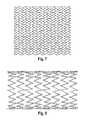
- FIG. 1is a view from above, of a slitted tube opened out flat
- FIG. 2shows a portion of the matrix of FIG. 1 , radially expanded (but also opened out flat)
- FIG. 3shows another embodiment of slitted tube opened out flat
- FIG. 4shows the FIG. 3 strut matrix, opened out flat, and expanded
- FIG. 5is a perspective view of the FIG. 4 strut matrix, not opened out flat
- FIG. 6is a view of another slitted tube opened out flat
- FIG. 7is a view of the slitted tube of FIG. 6 , radially expanded and opened out flat and
- FIG. 8is a perspective view of the radially expanded tube of FIGS. 6 and 7 ;
- FIG. 9is a view from above, like that of FIGS. 1 , 3 and 6 but of yet another embodiment of a slitted tube opened out flat.
- a slitted tube 10opened out flat by parting the slitted tube at interface portions 12 , 14 and 16 to display, opened out flat, a succession of stenting rings I, II, III, IV arranged next to each other along the length of the slitted tube parallel to its long axis direction X.
- Each of the four stenting ringsexhibits a serial progression of n t struts, here 24 struts, ( 20 ) separated from each other by the slits through the wall thickness of the tubular workpiece, the succeeding struts of each stenting ring being joined by successive cusps 24 .
- n t strutshere 24 struts
- each cuspis in “head-to-head” relationship, along the axis direction X of the slitted tube, with a cusp of the adjacent stenting ring.
- each stenting ringis connected to the next adjacent stenting ring by four bridges 26 distributed at regular intervals (90°) around the circumference of the slitted tube.
- a strut matrix made by slitting a precursor tubeis conventional.
- FIG. 2we see a portion of the FIG. 1 slitted tube radially expanded so that the struts of each stenting ring are inclined to the axial direction X and present themselves as a zig-zag sequence of struts around the circumference of the stent. It will be noted that the cusps 24 of adjacent stenting rings are still in head-to-head disposition. Skilled readers will appreciate that any gross bending of a deployed stent is liable to bring opposing cusps on the inside of the bend into physical contact with each other.
- each cusp 24is in head-to-head relationship with a cusp of the next adjacent stenting ring.
- each stenting ringis connected to the next adjacent stenting ring by four bridges 26 .
- the slits 22 in the tube 10are axially staggered relative to each other, in a way which is not present in drawing FIG. 1 .
- this axial staggeringthere is also axial staggering of the gaps 30 between each pair of facing cusps 24 .
- FIG. 3there is shown a greater axial separation between facing cusps 24 than is apparent from FIG. 1 , but this is not the decisive difference between the FIG. 1 concept and that of FIG. 3 .
- each cusppoints towards a gap between two adjacent cusps of the adjacent zig-zag stenting ring.
- each cuspis free to advance axially into the gap between two adjacent cusps of the adjacent stenting ring, rather than striking, head on, the facing cusp of the adjacent stenting ring, as in FIG. 2 .
- FIG. 5is a perspective view but shows the same phenomenon as is drawn in drawing FIG. 4 I with the same strut matrix.
- each stenting ringneed not be 24, and the number of bridges between adjacent stenting rings need not be four.
- Another arrangement that shows promiseis one in which each stenting ring has 42 struts and adjacent stenting rings are connected by three bridges distributed at 120° intervals. Such an arrangement is shown in FIG. 9 1 and is described below.
- FIGS. 6 , 7 and 8show another attractive design, namely, a slitted tube with 40 struts per ring and four bridges. Since other aspects of the design are described above with reference to FIGS. 3 and 4 , the same reference numbers are used to identify corresponding features. of the design. Again, it can be seen that when the FIG. 6 slitted tube is opened out radially, the cusps 24 automatically move to positions where they are no longer facing head to head any cusp of the adjacent zig-zag stenting ring, with consequential advantages of avoiding cusp to cusp contact when the deployed stent is subjected to bending deformation.
- Bridges Bland B 3connect loop III to loop IV.
- Bridge B 2is one of the four bridges that connect loop III.
- Between bridges B 1 and B 2 , and between bridge B 2 and B 3is a sequence of five struts.
- Three of these struts S 1 , S 2 , S 3have the same length. Each extends between two free cusps.
- the other two struts, S 4 and S 5have lengths different from each other. This length difference is what takes the free cusps of adjacent loops out of a head-to-head facing relationship in the expanded configuration of the stent, as can be understood from FIGS. 7 and 8 , which also reveal that the bridges are correspondingly skewed, relative to the long axis of the stent, in the expanded disposition of the stent.
- the lengthwise staggering of cusps that characterises the present inventioncan deliver useful technical effects that include the following.
- the designfeatures non-identical proximal and distal ends, so that it is critically important to load the stent in the delivery system with its distal end nearer the distal end of the delivery system.
- An advantage of the present inventionis that it permits the building of stents with identical distal and proximal ends, that are indifferent to the choice of stent end to lie closer to the distal end of the delivery system.
- the axial staggeringopens up possibilities for “recesses” such as recesses 40 in FIG. 3 , where radiopaque marker elements 50 can be located. These elements thus lie snug between circumferentially spaced apart cusps 42 , 44 and axially adjacent to intervening cusps 46 , to which it will be convenient to attach the marker. Any axial pushing on the stent, while the confining sleeve is withdrawn is customarily applied to the end surface of the stent.
- FIG. 3shows one possible arrangement of tantalum markers 60 , 62 , 64 , 66 which is not far from an even distribution in the compact form of the stent (although further from evenly distributed when the stent is expanded).
- FIG. 9design it is clear that each end of the stent offers only three recesses for installation of a set of three markers evenly distributed around the circumference of the stent.
- the markerscan be of different shapes, in order to meet these design objectives, as is illustrated in FIG. 6 , as one example.
- the present inventiondelivers a simple pattern of linear slits in the compact configuration that exhibits in each stenting loop a sequence of stepwise displacements, up and down the axis of the stent, in the positions of the free cusps, yet, in the expanded disposition of the stent, the axial steps are gone. Instead, the bridges are skewed, and the free cusps are circumferentially displaced, relative to the free cusps of the adjacent stenting loop that were facing them, head-to-head, in the compact disposition.
- the zig-zag struts of each stenting ringsmarch around the circumference of the lumen in a progression in which axial displacement of free cusps, relative to each other, is difficult to discern.
- the stenting loopsdeploys in a way that is close to an optimal planar hoop, transverse t the axis, for generating a large mechanical radially outward stenting force.
- Applicant's WO 2007/135090discloses a stent that is “bend-capable” in that cusps move out of a “head-to-head” facing relationship in the expanded deployed stent, when the stent tube is bent out of a straight configuration. It will be apparent to the skilled reader that the present invention (lengthwise staggering of cusps) can be combined with the invention of WO 2007/135090 (skewed unit cell) to deliver a stent matrix that avoids a head to head facing relationship of cusps, regardless of the extent to which the stent is bent out of a straight line after deployment.
- One way to accomplish the result explained in WO 2007/135090is to arrange the strut matrix such that n 8/2 is an even number.
- the stents taught in this disclosurecan be used in the same way as prior art stents are used. They can carry graft material, or drugs, for example. They can be delivered transluminally, by a suitable catheter delivery system. They can carry radiopaque markers, as is taught in the state of the art. They will find particular application in situations where the stent, after deployment, is subject to a high degree of bending.
- the present drawingsshow specific embodiments which are to be assessed as exemplary, not limiting.
- the stentneed not be made from shape memory metal and need not be laser cut.
- the inventive concept disclosed hereinis applicable to a wide range of known stent technologies.
Landscapes
- Health & Medical Sciences (AREA)
- Engineering & Computer Science (AREA)
- Biomedical Technology (AREA)
- Heart & Thoracic Surgery (AREA)
- Life Sciences & Earth Sciences (AREA)
- Cardiology (AREA)
- Oral & Maxillofacial Surgery (AREA)
- Transplantation (AREA)
- Veterinary Medicine (AREA)
- Vascular Medicine (AREA)
- Public Health (AREA)
- Animal Behavior & Ethology (AREA)
- General Health & Medical Sciences (AREA)
- Optics & Photonics (AREA)
- Physics & Mathematics (AREA)
- Media Introduction/Drainage Providing Device (AREA)
- Prostheses (AREA)
Abstract
Description
This application is a continuation of U.S. patent application Ser. No. 12/594,531, filed Dec. 7, 2009, now U.S. Pat. No. 8,518,101, which is a U.S. national stage application under 35 USC §371 of International Application No. PCT/EP2008/054007, filed Apr. 3, 2008, claiming priority to United Kingdom Patent Application No. 0706499.1, filed Apr. 3, 2007, each of which is incorporated by reference in its entirety into this application.
This invention relates to radially expansible stents for transluminal delivery to a stenting site within the body of a patient, the stent having an enhanced capacity for bending, after deployment in the body.
There are some stenting sites within the body in which there is substantial deformation of the lumen that is stented. Consider, for example, a peripheral vascular stent at a site near the knee. When an expanded stent suffers severe bending, there can be buckling on the inside of the bend. Even before there is any catastrophic buckling, the likelihood exists that portions of the stent matrix, spaced apart along the axis of the stent lumen, will approach each other and impact, on the inside of any temporary tight bend, to the detriment not only of the tissue caught between the impacting portions of the stent, but also the stent matrix itself. It is an object to the present invention to ameliorate this problem.
The present applicant is a specialist in the manufacture of stents of nickel-titanium shape memory alloy, manufactured from a raw material that is a tubular workpiece of that alloy. To make the stent matrix, the alloy tube workpiece is subjected to a laser-cutting step in which the laser cuts a multiplicity of slits in the tubular workpiece. Each slit extends through the entire wall thickness of the tube, and for the most part, the slits all have the same length and are all parallel to the longitudinal axis of the tubular workpiece. When one advances around the circumference of the tubular workpiece, crossing transversely over a multiplicity of the slits, one by one, alternate slits that one crosses are staggered, in the axial direction of the tube, by a distance that is around half the length of each slit. When such a slitted tube is slipped over a mandrel, and expanded radially, each slit opens out into a diamond-shaped aperture in the wall thickness of the tube. Looked at in another way, the creation of the slits at the same time creates struts of material that lie between adjacent slits, and the struts in the radially expanded tube emerge as zig-zag stenting rings with a characteristic strut length within any one zig-zag ring that is more or less half the length of each of the slits cut by the laser.
Where two struts, next adjacent within the circumference of a zig-zag ring, come together, we can call this a “cusp”. The cusps of each zig-zag ring are contiguous with cusps of the next adjacent stenting ring.
For enhanced flexibility of the zig-zag stent matrix, many of the “connector portions” between facing cusps of adjacent zig-zag stenting rings can be parted, to leave only a few (typically four or less) connector bridges between any two axially adjacent zig-zag stenting rings. See our WO 94/17754. The surviving connector bridges have a length direction parallel to the longitudinal axis of the stent matrix.
However where these connector bridges have been removed, there are still cusps of adjacent zig-zag stenting rings that are effectively “head to head” across the narrow gap with a cusp belonging to the adjacent zig-zag ring. When such a narrow gap is on the inside of the bend, upon bending the expanded stent (by movement of the body after the stent has been placed in the body), there is the likelihood of the two cusps head to head impacting on each other. It is common to call this “peak to peak”.
In this discussion, it is important to distinguish between the radially compact trans-luminal delivery disposition of the stent matrix (not very different from the as-cut disposition of the stent matrix, before expansion on the mandrel to diamond-shaped apertures) and the radially expanded and deployed configuration of the stent, where the struts form zig-zag rings. A head to head facing configuration of parted connector portion cusps is tolerable for the delivery procedure but to be avoided, if that is feasible, after stent deployment and radial expansion.
The present applicant has been interested in this objective for some years. For a previous proposal for improvements see its WO 01/76508/ published Oct. 18, 2001. The present invention represents a fresh approach to the problem and, it is thought, a more elegant solution.
Other makers of stents have concerned themselves with the same objective. See for example US 2004/0073290 A1 where {paragraph 0002) it is explained that “if adjacent rings are spaced too close together” then “interference can occur between adjacent rings on the inside of a bend”. Clearly, the idea of spacing the axially adjacent rings further apart has limited appeal/because it leaves the space between the rings unstented.
Self-expanding stents of nickel-titanium shape memory alloy are not particularly radiopaque and so are often equipped with radiopaque markers, of which one favoured material is tantalum because it is close to the nickel-titanium alloy in electrochemical potential/thereby minimising galvanic corrosion in the electrolyte of a bodily fluid.
Self-expanding stents are usually deployed by proximal withdrawal of a sheath of a catheter delivery system. To prevent the stent moving proximally with the withdrawing sheath it is conventional to use a pushing annulus, that abuts the proximal end zone of the stent and resists any proximal movement of the stent relative to the stent delivery catheter as such. As stent performance and length go up so does the compressive stress imposed on the end zone of the stent by the pushing annulus during withdrawal. It is important to avoid imposing on any part of the end zone a magnitude of stress higher than that of the design performance limits for that stent. The present inventor knows that one way to manage that peak stress is to build the stent so that the end zone has all its cusps touching a notional circle transverse to the longitudinal axis of the stent, so that the stress from the pushing annulus is shared equally amongst all those cusps. For an example of a stent with such an end zone, see WO 2006/047977.
EP-A-1767240 offers ways to increase the flexibility of a stent in its radially compact delivery disposition. It suggests resorting to portions not parallel to the stent length, such as struts that are curved, or bridges that are skewed to the long axis of the stent.
The present invention is defined in the claims below in which different aspects are presented in respective independent claims, and dependent claims are directed to optional or preferred features. In one embodiment, the invention takes the form of a laser-cut stent in which the slits cut by the laser in the tubular workpiece that is the precursor of the stent are staggered with respect to each other, in the length direction of the stent cylinder such that the slits cut by the laser are, in general, all the same length but the struts created by cutting the laser slits are not all the same length because the axial stagger between circumferentially adjacent slits is arranged to be something other than half the common slit length. However, as the accompanying drawings will reveal, even when many of the slits can be made free of axial displacement (staggering) relative to the circumferentially next adjacent slits, the effect of eliminating head to head cusps on adjacent stenting rings can still be accomplished. As long as some of the adjacent slits are staggered, by an amount other than a one half slit length, the necessary circumferential displacement of facing cusps away from each other can still be achieved, as the slitted tube undergoes radial expansion.
Referring toFIG. 1 , we see a slittedtube 10, opened out flat by parting the slitted tube atinterface portions successive cusps 24. In the unexpanded slitted configuration ofFIG. 1 , each cusp is in “head-to-head” relationship, along the axis direction X of the slitted tube, with a cusp of the adjacent stenting ring. As can be seen, each stenting ring is connected to the next adjacent stenting ring by fourbridges 26 distributed at regular intervals (90°) around the circumference of the slitted tube. The number of bridges per ring is nsand the number of struts between successive bridges is nsso: nt=s•nb.
In stent technology, particularly stents made of shape memory alloy (NITINOL), a strut matrix made by slitting a precursor tube is conventional.
Turning toFIG. 2 , we see a portion of theFIG. 1 slitted tube radially expanded so that the struts of each stenting ring are inclined to the axial direction X and present themselves as a zig-zag sequence of struts around the circumference of the stent. It will be noted that thecusps 24 of adjacent stenting rings are still in head-to-head disposition. Skilled readers will appreciate that any gross bending of a deployed stent is liable to bring opposing cusps on the inside of the bend into physical contact with each other.
Turning toFIG. 3 , we can recognise the same pattern of 24struts 20 making up 4 adjacent stenting rings I, II, III, IV, recognisably equivalent to what is shown inFIG. 1 . Further, just as inFIG. 1 , eachcusp 24 is in head-to-head relationship with a cusp of the next adjacent stenting ring. Just as inFIG. 1 , each stenting ring is connected to the next adjacent stenting ring by fourbridges 26.
However, theslits 22 in thetube 10, that have created the strut matrix, are axially staggered relative to each other, in a way which is not present in drawingFIG. 1 . In consequence of this axial staggering, there is also axial staggering of thegaps 30 between each pair of facingcusps 24. InFIG. 3 , there is shown a greater axial separation between facingcusps 24 than is apparent fromFIG. 1 , but this is not the decisive difference between theFIG. 1 concept and that ofFIG. 3 .
Reverting toFIG. 1 , and concentrating on a pair of struts defining between them anindividual gap 22, one can see that the axial length of the two struts, one each side of theslit 22 1 is the same. However, when we look atFIG. 3 , and aparticular slit 22, we notice that the length of the strut that extends down each side of theslit 22, from thecommon cusp 24 at one end of the slit, are different. This has repercussions for the way the struts deform when the slitted tube ofFIG. 3 is radially expanded, to the zig-zag pattern shown inFIG. 4 .
ComparingFIG. 4 withFIG. 2 , it is immediately evident that there are no longer pairs ofcusps 24 facing each other, head to head. Instead, each cusp points towards a gap between two adjacent cusps of the adjacent zig-zag stenting ring. The skilled reader will appreciate that when the stent ofFIG. 4 is bent (into a banana shape) each cusp is free to advance axially into the gap between two adjacent cusps of the adjacent stenting ring, rather than striking, head on, the facing cusp of the adjacent stenting ring, as inFIG. 2 .
The skilled reader will grasp that the number of struts in each stenting ring need not be 24, and the number of bridges between adjacent stenting rings need not be four. Another arrangement that shows promise is one in which each stenting ring has42 struts and adjacent stenting rings are connected by three bridges distributed at 120° intervals. Such an arrangement is shown inFIG. 9 1 and is described below.
InFIG. 6 , in loop III, three successive bridges are labeled B1, B2, B3. Bridges Bland B3 connect loop III to loop IV. Bridge B2 is one of the four bridges that connect loop III. Between bridges B1 and B2, and between bridge B2 and B3, is a sequence of five struts. Three of these struts S1, S2, S3, have the same length. Each extends between two free cusps. The other two struts, S4 and S5, have lengths different from each other. This length difference is what takes the free cusps of adjacent loops out of a head-to-head facing relationship in the expanded configuration of the stent, as can be understood fromFIGS. 7 and 8 , which also reveal that the bridges are correspondingly skewed, relative to the long axis of the stent, in the expanded disposition of the stent.
The lengthwise staggering of cusps that characterises the present invention can deliver useful technical effects that include the following.
When a self-expanding strut is to be released from its catheter delivery system, the usual way is to withdraw proximally, relative to the stent, a restraining sheath that surrounds its abluminal surface. When all cusps in a loop are at the same point along the axis of the stent, all can spring radially outwardly from the sheath simultaneously. This impulsive release is not ideal for controlled release. Axial staggering of cusps can assist in releasing the stent more progressively and steadily, cusps escaping one by one from the inward radial confinement of the proximally retreating sheath.
For some stents, the design features non-identical proximal and distal ends, so that it is critically important to load the stent in the delivery system with its distal end nearer the distal end of the delivery system. An advantage of the present invention is that it permits the building of stents with identical distal and proximal ends, that are indifferent to the choice of stent end to lie closer to the distal end of the delivery system.
The axial staggering opens up possibilities for “recesses” such asrecesses 40 inFIG. 3 , whereradiopaque marker elements 50 can be located. These elements thus lie snug between circumferentially spaced apart cusps42,44 and axially adjacent to interveningcusps 46, to which it will be convenient to attach the marker. Any axial pushing on the stent, while the confining sleeve is withdrawn is customarily applied to the end surface of the stent. By locating markers in the end recesses and arranging for the end elevation of the stent to comprise both cusps and markers, the stresses on the end elevation are distributed around the circumference as evenly as possible, and over the maximum area of surface of the implant, which is good for fatigue performance, quality control, and efficiency of stent release. Finally, with markers recessed into the end zone of a stent, the markers when imaged give a true impression of where the stent matrix is, and where it is not. A short look at US 2006/0025847 serves to reveal the advantages of the present proposal over another recent proposal to deal with pushing forces.
Not to be underestimated is the advantage yielded by this invention, that a “peak-to-valley” distribution of cusps in the expanded deployed disposition is automatic, regardless how short are the bridges between adjacent stenting loops. Short, strong, robust bridges that connect axially adjacent stenting loops are greatly to be welcomed, for many reasons. In particular/they are less vulnerable to inadvertent straining (bad for fatigue performance if nothing else) when stent matrices are being installed in a catheter delivery system, or when being deployed out of one. Put another way, the stent with short stubby bridges can be rated for greater loads imposed on it during loading or deployment. Since the radial force that a stent can exert on surrounding bodily tissue increases with the number of stenting loops per unit (axial) length of the stent, a reduction in the length of the bridges connecting axially adjacent stenting loops will give rise to an increased stenting force.
However, short stubby bridges are disadvantageous, to the extent that they prejudice stent flexibility. The more flexible a stent is, the better its resistance to fatigue failure (other things being equal). One way to deliver more flexibility, despite an absence of much flexibility in the bridges, is to increase the number of struts in the sequence of struts between each bridge and the next bridge. On that basis, the arrangement ofFIG. 9 , with 7 struts between any two bridges B1, B2 or B2, B3, is superior to theFIG. 6 design with 5 struts, itself superior to that ofFIG. 3 , with 3 struts.
When it comes to radiopaque markers, it is important to arrange the markers so that they are distributed around the circumference of the stent, in the radially compact delivery disposition of the stent, as evenly as is practicable. InFIG. 3 , the arrangement is even.FIG. 6 shows one possible arrangement oftantalum markers FIG. 9 design it is clear that each end of the stent offers only three recesses for installation of a set of three markers evenly distributed around the circumference of the stent.
The markers can be of different shapes, in order to meet these design objectives, as is illustrated inFIG. 6 , as one example.
One thing that is striking about the present invention is how it delivers a simple pattern of linear slits in the compact configuration that exhibits in each stenting loop a sequence of stepwise displacements, up and down the axis of the stent, in the positions of the free cusps, yet, in the expanded disposition of the stent, the axial steps are gone. Instead, the bridges are skewed, and the free cusps are circumferentially displaced, relative to the free cusps of the adjacent stenting loop that were facing them, head-to-head, in the compact disposition. Of significance is that, in the expanded disposition, when the stent must exert radially outward stenting force on the bodily tissue that forms the wall of the stented bodily lumen, the zig-zag struts of each stenting rings march around the circumference of the lumen in a progression in which axial displacement of free cusps, relative to each other, is difficult to discern. Instead, the stenting loops deploys in a way that is close to an optimal planar hoop, transverse t the axis, for generating a large mechanical radially outward stenting force.
Applicant's WO 2007/135090 discloses a stent that is “bend-capable” in that cusps move out of a “head-to-head” facing relationship in the expanded deployed stent, when the stent tube is bent out of a straight configuration. It will be apparent to the skilled reader that the present invention (lengthwise staggering of cusps) can be combined with the invention of WO 2007/135090 (skewed unit cell) to deliver a stent matrix that avoids a head to head facing relationship of cusps, regardless of the extent to which the stent is bent out of a straight line after deployment. One way to accomplish the result explained in WO 2007/135090 is to arrange the strut matrix such that n 8/2 is an even number.
It hardly needs to be added, that the stents taught in this disclosure can be used in the same way as prior art stents are used. They can carry graft material, or drugs, for example. They can be delivered transluminally, by a suitable catheter delivery system. They can carry radiopaque markers, as is taught in the state of the art. They will find particular application in situations where the stent, after deployment, is subject to a high degree of bending.
The present drawings show specific embodiments which are to be assessed as exemplary, not limiting. The stent need not be made from shape memory metal and need not be laser cut. The inventive concept disclosed herein is applicable to a wide range of known stent technologies.
Claims (12)
1. A stent comprising
a matrix of struts disposed parallel to one another comprising:
a plurality of loops disposed along a longitudinal axis of the stent comprising:
end-zone loops composed of tied cusps, free cusps and radiopaque markers;
and
intermediate-zone loops composed of tied cusps and free cusps,
wherein tied cusps and free cusps of end-zone loops and intermediate-zone loops connect adjacent struts;
and
a bridge connecting a tied cusp of one loop head-to-head with a tied cusp of an adjacent loop
wherein all of the free cusps on one end of the end-zone loop and all of the radiopaque markers of the end-zone loop are disposed to touch a notional circle transverse to the longitudinal axis of the stent such that the stress imposed on the stent by a pushing annulus is shared among all of the free cusps and all of the radiopaque markers on the one end of the end-zone loops;
wherein the radiopaque markers are distributed around the circumference of the end-zone loops, each of the markers positioned in a gap defined between outer surfaces of adjacent end cusps;
and
wherein the adjacent struts connected by a tied cusp have different lengths, and at least one free cusp in each loop joins two struts of approximately equal length.
2. The stent according toclaim 1 wherein free cusps of adjacent loops are circumferentially displaced from one another.
3. The stent according toclaim 2 , wherein each intermediate loop includes either 24, 40, or 42 struts.
4. The stent according toclaim 3 wherein the stent includes 40 struts in each loop and 4 bridges connecting each pair of adjacent loops, and at least three consecutive struts having approximately equal lengths located between adjacent bridges.
5. The stent according toclaim 3 wherein the stent includes 42 struts in each loop and 3 bridges connecting any two loops, and at least five consecutive struts having approximately equal lengths located between adjacent bridges.
6. The stent according toclaim 2 wherein the bridges between any two adjacent intermediate-zone loops are evenly distributed around the circumference.
7. The stent according toclaim 6 wherein radiopaque markers in an end zone of the stent are evenly spaced around the circumference.
8. The stent according toclaim 7 wherein at least two radiopaque markers have shapes different from each other.
9. The stent according toclaim 8 wherein at least three radiopaque markers each have a different shape from one another.
10. The stent according toclaim 1 wherein there are N struts between two successive bridges connecting two adjacent loops A and B, N being an integral even number, and N/2 being an integral odd number.
11. The stent according toclaim 1 wherein there are N struts between successive bridges connecting two adjacent loops A and B, N being an integral even number, and N/2 being also an integral even number.
12. The stent according toclaim 1 wherein at least three radiopaque markers have a different shape from one another.
Priority Applications (2)
| Application Number | Priority Date | Filing Date | Title |
|---|---|---|---|
| US13/975,147US9050203B2 (en) | 2007-04-03 | 2013-08-23 | Bendable stent |
| US14/728,981US9668895B2 (en) | 2007-04-03 | 2015-06-02 | Bendable stent |
Applications Claiming Priority (5)
| Application Number | Priority Date | Filing Date | Title |
|---|---|---|---|
| GB0706499.1 | 2007-04-03 | ||
| GBGB0706499.1AGB0706499D0 (en) | 2007-04-03 | 2007-04-03 | Bendable stent |
| PCT/EP2008/054007WO2008119837A2 (en) | 2007-04-03 | 2008-04-03 | Bendable stent |
| US59453109A | 2009-12-07 | 2009-12-07 | |
| US13/975,147US9050203B2 (en) | 2007-04-03 | 2013-08-23 | Bendable stent |
Related Parent Applications (3)
| Application Number | Title | Priority Date | Filing Date |
|---|---|---|---|
| US12/594,531ContinuationUS8518101B2 (en) | 2007-04-03 | 2008-04-03 | Bendable stent |
| PCT/EP2008/054007ContinuationWO2008119837A2 (en) | 2007-04-03 | 2008-04-03 | Bendable stent |
| US59453109AContinuation | 2007-04-03 | 2009-12-07 |
Related Child Applications (1)
| Application Number | Title | Priority Date | Filing Date |
|---|---|---|---|
| US14/728,981DivisionUS9668895B2 (en) | 2007-04-03 | 2015-06-02 | Bendable stent |
Publications (2)
| Publication Number | Publication Date |
|---|---|
| US20130345791A1 US20130345791A1 (en) | 2013-12-26 |
| US9050203B2true US9050203B2 (en) | 2015-06-09 |
Family
ID=38050774
Family Applications (3)
| Application Number | Title | Priority Date | Filing Date |
|---|---|---|---|
| US12/594,531Active2028-04-19US8518101B2 (en) | 2007-04-03 | 2008-04-03 | Bendable stent |
| US13/975,147ActiveUS9050203B2 (en) | 2007-04-03 | 2013-08-23 | Bendable stent |
| US14/728,981Active2028-07-08US9668895B2 (en) | 2007-04-03 | 2015-06-02 | Bendable stent |
Family Applications Before (1)
| Application Number | Title | Priority Date | Filing Date |
|---|---|---|---|
| US12/594,531Active2028-04-19US8518101B2 (en) | 2007-04-03 | 2008-04-03 | Bendable stent |
Family Applications After (1)
| Application Number | Title | Priority Date | Filing Date |
|---|---|---|---|
| US14/728,981Active2028-07-08US9668895B2 (en) | 2007-04-03 | 2015-06-02 | Bendable stent |
Country Status (4)
| Country | Link |
|---|---|
| US (3) | US8518101B2 (en) |
| EP (2) | EP2134301B1 (en) |
| GB (1) | GB0706499D0 (en) |
| WO (1) | WO2008119837A2 (en) |
Families Citing this family (33)
| Publication number | Priority date | Publication date | Assignee | Title |
|---|---|---|---|---|
| GB0020491D0 (en) | 2000-08-18 | 2000-10-11 | Angiomed Ag | Stent with attached element and method of making such a stent |
| GB0609841D0 (en) | 2006-05-17 | 2006-06-28 | Angiomed Ag | Bend-capable tubular prosthesis |
| GB0609911D0 (en)* | 2006-05-18 | 2006-06-28 | Angiomed Ag | Bend-capable stent prosthesis |
| GB0616579D0 (en)* | 2006-08-21 | 2006-09-27 | Angiomed Ag | Self-expanding stent |
| GB0616729D0 (en)* | 2006-08-23 | 2006-10-04 | Angiomed Ag | Method of welding a component to a shape memory alloy workpiece |
| GB0616999D0 (en) | 2006-08-29 | 2006-10-04 | Angiomed Ag | Annular mesh |
| EP2063824B1 (en) | 2006-09-07 | 2020-10-28 | Angiomed GmbH & Co. Medizintechnik KG | Helical implant having different ends |
| GB0622465D0 (en) | 2006-11-10 | 2006-12-20 | Angiomed Ag | Stent |
| GB0624419D0 (en) | 2006-12-06 | 2007-01-17 | Angiomed Ag | Stenting ring with marker |
| GB0703379D0 (en)* | 2007-02-21 | 2007-03-28 | Angiomed Ag | Stent with radiopaque marker |
| GB0706499D0 (en) | 2007-04-03 | 2007-05-09 | Angiomed Ag | Bendable stent |
| GB0717481D0 (en) | 2007-09-07 | 2007-10-17 | Angiomed Ag | Self-expansible stent with radiopaque markers |
| WO2010077973A2 (en)* | 2008-12-17 | 2010-07-08 | Sanjay Shrivastava | Methods and apparatus for filtering a body lumen |
| GB0908315D0 (en)* | 2009-05-14 | 2009-06-24 | Angiomed Ag | Stent |
| MX2013001444A (en)* | 2010-08-02 | 2013-03-12 | Cordis Corp | Flexible helical stent having different helical regions. |
| US8840659B2 (en)* | 2011-04-28 | 2014-09-23 | Cook Medical Technologies Llc | Stent and stent-graft designs |
| KR101410623B1 (en)* | 2012-03-02 | 2014-06-20 | 주식회사 시브이바이오 | Stent for improving crookedness |
| US9233015B2 (en) | 2012-06-15 | 2016-01-12 | Trivascular, Inc. | Endovascular delivery system with an improved radiopaque marker scheme |
| DE102013104550B4 (en) | 2013-05-03 | 2021-07-01 | Acandis Gmbh | Medical device for insertion into a hollow organ in the body |
| WO2017044655A1 (en) | 2015-09-08 | 2017-03-16 | Transit Scientific, LLC | Exoskeleton devices for use with elongated medical instruments |
| US10758381B2 (en) | 2016-03-31 | 2020-09-01 | Vesper Medical, Inc. | Intravascular implants |
| US10368991B2 (en) | 2017-02-06 | 2019-08-06 | C. R. Bard, Inc. | Device and associated percutaneous minimally invasive method for creating a venous valve |
| US10849769B2 (en) | 2017-08-23 | 2020-12-01 | Vesper Medical, Inc. | Non-foreshortening stent |
| US11357650B2 (en) | 2019-02-28 | 2022-06-14 | Vesper Medical, Inc. | Hybrid stent |
| US11628076B2 (en) | 2017-09-08 | 2023-04-18 | Vesper Medical, Inc. | Hybrid stent |
| US10271977B2 (en) | 2017-09-08 | 2019-04-30 | Vesper Medical, Inc. | Hybrid stent |
| WO2019084567A1 (en)* | 2017-10-27 | 2019-05-02 | Transit Scientific, LLC | Exoskeleton device with expandable section for scoring |
| US11406801B2 (en) | 2017-10-27 | 2022-08-09 | Transit Scientific, LLC | Exoskeleton device with expandable section for scoring |
| US11364134B2 (en) | 2018-02-15 | 2022-06-21 | Vesper Medical, Inc. | Tapering stent |
| US10500078B2 (en) | 2018-03-09 | 2019-12-10 | Vesper Medical, Inc. | Implantable stent |
| WO2021030632A1 (en)* | 2019-08-13 | 2021-02-18 | Transit Scientific, LLC | Exoskeleton device with expandable section for scoring |
| US12036138B2 (en)* | 2021-07-30 | 2024-07-16 | Stryker Corporation | Medical stents |
| US20250248833A1 (en)* | 2024-02-07 | 2025-08-07 | DyQure LLC | Conical stent for intracranial angioplasty and methods of stent placement for prevention and treatment of ischemic stroke |
Citations (148)
| Publication number | Priority date | Publication date | Assignee | Title |
|---|---|---|---|---|
| GB453944A (en) | 1935-04-10 | 1936-09-22 | John Walter Anderson | Improvements in couplings for vehicles |
| FR2626046A1 (en) | 1988-01-18 | 1989-07-21 | Caoutchouc Manuf Plastique | Device for joining panels or for producing conduits and its applications |
| US5091205A (en) | 1989-01-17 | 1992-02-25 | Union Carbide Chemicals & Plastics Technology Corporation | Hydrophilic lubricious coatings |
| EP0481365A1 (en) | 1990-10-13 | 1992-04-22 | Angiomed Ag | Device for expanding a stenosis in a body duct |
| WO1994017754A1 (en) | 1993-02-04 | 1994-08-18 | Angiomed Ag | Stent |
| WO1995003010A1 (en) | 1993-07-23 | 1995-02-02 | Cook Incorporated | A flexible stent having a pattern formed from a sheet of material |
| US5464419A (en) | 1993-03-22 | 1995-11-07 | Industrial Research B.V. | Expandable hollow sleeve for the local support and/or reinforcement of a body vessel, and method for the fabrication thereof |
| JPH07315147A (en) | 1994-05-23 | 1995-12-05 | Nishikawa Rubber Co Ltd | Drip weather strip mounting structure |
| EP0709068A2 (en) | 1994-10-27 | 1996-05-01 | Medinol Ltd. | X-ray visible stent |
| US5527353A (en) | 1993-12-02 | 1996-06-18 | Meadox Medicals, Inc. | Implantable tubular prosthesis |
| WO1996026689A1 (en) | 1995-03-01 | 1996-09-06 | Scimed Life Systems, Inc. | Improved longitudinally flexible expandable stent |
| US5591223A (en) | 1992-11-23 | 1997-01-07 | Children's Medical Center Corporation | Re-expandable endoprosthesis |
| DE29621207U1 (en) | 1996-12-06 | 1997-01-30 | MAN Roland Druckmaschinen AG, 63075 Offenbach | Fastening a heat sink on a printed circuit board |
| US5645532A (en) | 1996-03-04 | 1997-07-08 | Sil-Med Corporation | Radiopaque cuff peritoneal dialysis catheter |
| WO1997033534A1 (en) | 1996-03-13 | 1997-09-18 | Medtronic, Inc. | Radiopaque stent markers |
| EP0800800A1 (en) | 1996-04-10 | 1997-10-15 | Variomed AG | Stent for transluminal implantation in a hollow organ |
| US5725572A (en) | 1994-04-25 | 1998-03-10 | Advanced Cardiovascular Systems, Inc. | Radiopaque stent |
| US5741327A (en) | 1997-05-06 | 1998-04-21 | Global Therapeutics, Inc. | Surgical stent featuring radiopaque markers |
| WO1998020810A1 (en) | 1996-11-12 | 1998-05-22 | Medtronic, Inc. | Flexible, radially expansible luminal prostheses |
| US5759192A (en) | 1994-11-28 | 1998-06-02 | Advanced Cardiovascular Systems, Inc. | Method and apparatus for direct laser cutting of metal stents |
| EP0847733A1 (en) | 1996-12-10 | 1998-06-17 | BIOTRONIK Mess- und Therapiegeräte GmbH & Co Ingenieurbüro Berlin | Stent |
| US5800511A (en) | 1993-01-19 | 1998-09-01 | Schneider (Usa) Inc | Clad composite stent |
| EP0870483A2 (en) | 1997-03-14 | 1998-10-14 | Nozomu Kanesaka | Flexible stent |
| US5824042A (en) | 1996-04-05 | 1998-10-20 | Medtronic, Inc. | Endoluminal prostheses having position indicating markers |
| US5824059A (en) | 1997-08-05 | 1998-10-20 | Wijay; Bandula | Flexible stent |
| US5843118A (en) | 1995-12-04 | 1998-12-01 | Target Therapeutics, Inc. | Fibered micro vaso-occlusive devices |
| DE19728337A1 (en) | 1997-07-03 | 1999-01-07 | Inst Mikrotechnik Mainz Gmbh | Implantable stent |
| US5858556A (en) | 1997-01-21 | 1999-01-12 | Uti Corporation | Multilayer composite tubular structure and method of making |
| US5868783A (en) | 1997-04-16 | 1999-02-09 | Numed, Inc. | Intravascular stent with limited axial shrinkage |
| WO1999015108A2 (en) | 1997-09-24 | 1999-04-01 | Med Institute, Inc. | Radially expandable stent |
| DE29904817U1 (en) | 1999-03-16 | 1999-05-27 | amg Handelsgesellschaft für angewandte Medizin- und Gesundheitstechnik mbH, 46348 Raesfeld | Blood vessel support device |
| US5922020A (en) | 1996-08-02 | 1999-07-13 | Localmed, Inc. | Tubular prosthesis having improved expansion and imaging characteristics |
| WO1999038457A1 (en) | 1998-02-03 | 1999-08-05 | Jang G David | Tubular stent consisting of horizontal expansion struts and contralaterally attached diagonal-connectors |
| WO1999049928A1 (en) | 1998-03-30 | 1999-10-07 | Conor Medsystems, Inc. | Expandable medical device with ductile hinges |
| WO1999055253A1 (en) | 1998-04-27 | 1999-11-04 | Microval (S.A.R.L.) | Tubular and flexible vascular prosthesis |
| US6022374A (en) | 1997-12-16 | 2000-02-08 | Cardiovasc, Inc. | Expandable stent having radiopaque marker and method |
| US6053940A (en) | 1995-10-20 | 2000-04-25 | Wijay; Bandula | Vascular stent |
| US6056187A (en) | 1996-06-25 | 2000-05-02 | International Business Machines Corporation | Modular wire band stent |
| US6086611A (en) | 1997-09-25 | 2000-07-11 | Ave Connaught | Bifurcated stent |
| US6099561A (en) | 1996-10-21 | 2000-08-08 | Inflow Dynamics, Inc. | Vascular and endoluminal stents with improved coatings |
| WO2000045742A1 (en) | 1999-02-02 | 2000-08-10 | C.R. Bard, Inc. | Covered stent with encapsulated ends |
| EP1029517A2 (en) | 1999-01-14 | 2000-08-23 | Medtronic Inc. | Staggered endoluminal stent |
| WO2000049971A1 (en) | 1999-02-26 | 2000-08-31 | Advanced Cardiovascular Systems, Inc. | Stent with customized flexibility |
| EP1034751A2 (en) | 1999-03-05 | 2000-09-13 | Terumo Kabushiki Kaisha | Implanting stent and dilating device |
| WO2000064375A1 (en) | 1999-04-22 | 2000-11-02 | Advanced Cardiovascular Systems, Inc. | Radiopaque stents |
| WO2001001889A1 (en) | 1999-07-02 | 2001-01-11 | Scimed Life Systems, Inc. | Spiral wound stent |
| US6174329B1 (en) | 1996-08-22 | 2001-01-16 | Advanced Cardiovascular Systems, Inc. | Protective coating for a stent with intermediate radiopaque coating |
| WO2001032102A1 (en) | 1999-10-29 | 2001-05-10 | Angiomed Gmbh & Co. Medizintechnik Kg | Method of making a stent |
| WO2001058384A1 (en) | 2000-02-14 | 2001-08-16 | Angiomed Gmbh & Co. Medizintechnik Kg | Stent matrix |
| WO2001076508A2 (en) | 2000-04-12 | 2001-10-18 | Angiomed Gmbh & Co. Medizintechnik Kg | Self-expanding memory metal stent and method of making it |
| EP1157673A2 (en) | 2000-05-26 | 2001-11-28 | Variomed AG | Stent, position's element and delivery catheter |
| US20020007212A1 (en)* | 1995-03-01 | 2002-01-17 | Brown Brian J. | Longitudinally flexible expandable stent |
| WO2002015820A2 (en) | 2000-08-18 | 2002-02-28 | Angiomed Gmbh & Co. Medizintechnik Kg | Implant with attached element and method of making such an implant |
| EP1190685A2 (en) | 2000-09-22 | 2002-03-27 | Cordis Corporation | Stent with optimal strength and radiopacity characteristics |
| US6379381B1 (en) | 1999-09-03 | 2002-04-30 | Advanced Cardiovascular Systems, Inc. | Porous prosthesis and a method of depositing substances into the pores |
| US6387123B1 (en) | 1999-10-13 | 2002-05-14 | Advanced Cardiovascular Systems, Inc. | Stent with radiopaque core |
| EP1212991A2 (en) | 2000-12-07 | 2002-06-12 | Cordis Corporation | An intravascular device with improved radiopacity |
| WO2002049544A1 (en) | 2000-12-19 | 2002-06-27 | Vascular Architects, Inc. | Biologically active agent delivery apparatus and method |
| US20020116044A1 (en) | 2000-05-22 | 2002-08-22 | Cottone, Robert John | Self-expanding stent |
| US20020116051A1 (en) | 1992-02-21 | 2002-08-22 | Cragg Andrew H. | Intraluminal stent and graft |
| US6451047B2 (en) | 1995-03-10 | 2002-09-17 | Impra, Inc. | Encapsulated intraluminal stent-graft and methods of making same |
| US20020138136A1 (en) | 2001-03-23 | 2002-09-26 | Scimed Life Systems, Inc. | Medical device having radio-opacification and barrier layers |
| EP1245203A2 (en) | 2001-03-30 | 2002-10-02 | Terumo Kabushiki Kaisha | Stent |
| US6471721B1 (en) | 1999-12-30 | 2002-10-29 | Advanced Cardiovascular Systems, Inc. | Vascular stent having increased radiopacity and method for making same |
| US6475233B2 (en) | 1997-04-08 | 2002-11-05 | Interventional Technologies, Inc. | Stent having tapered struts |
| US6478816B2 (en) | 1998-07-08 | 2002-11-12 | Scimed Life Systems, Inc. | Stent |
| US20020193867A1 (en) | 2001-06-19 | 2002-12-19 | Gladdish Bennie W. | Low profile improved radiopacity intraluminal medical device |
| US20020198589A1 (en) | 2001-06-22 | 2002-12-26 | Leong Veronica Jade | Tessellated stent and method of manufacture |
| US20030055485A1 (en) | 2001-09-17 | 2003-03-20 | Intra Therapeutics, Inc. | Stent with offset cell geometry |
| US6540777B2 (en) | 2001-02-15 | 2003-04-01 | Scimed Life Systems, Inc. | Locking stent |
| US6547818B1 (en) | 2000-10-20 | 2003-04-15 | Endotex Interventional Systems, Inc. | Selectively thinned coiled-sheet stents and methods for making them |
| US6585757B1 (en) | 1999-09-15 | 2003-07-01 | Advanced Cardiovascular Systems, Inc. | Endovascular stent with radiopaque spine |
| WO2003055414A1 (en) | 2001-10-18 | 2003-07-10 | Advanced Stent Technologies, Inc. | Stent for vessel support, coverage and side branch accessibility |
| US20030135254A1 (en) | 1997-01-09 | 2003-07-17 | Maria Curcio | Stent for angioplasty and a production process therefor |
| DE10201151A1 (en) | 2002-01-15 | 2003-07-31 | Qualimed Innovative Med Prod | Surgical stent design of metal strut framework integrates marker between frame struts and of equal or lesser thickness than struts to identifiy stent position throughout service. |
| US6605110B2 (en) | 2001-06-29 | 2003-08-12 | Advanced Cardiovascular Systems, Inc. | Stent with enhanced bendability and flexibility |
| WO2003075797A2 (en) | 2002-03-14 | 2003-09-18 | Angiomed Gmbh & Co. Medizintechnik Kg | Mri compatible stent and method of manufacturing the same_______ |
| US6629994B2 (en) | 2001-06-11 | 2003-10-07 | Advanced Cardiovascular Systems, Inc. | Intravascular stent |
| US20030216807A1 (en) | 2002-05-16 | 2003-11-20 | Jones Donald K. | Intravascular stent device |
| US20030225448A1 (en) | 2002-05-28 | 2003-12-04 | Scimed Life Systems, Inc. | Polar radiopaque marker for stent |
| US20040015229A1 (en) | 2002-07-22 | 2004-01-22 | Syntheon, Llc | Vascular stent with radiopaque markers |
| US20040034402A1 (en) | 2002-07-26 | 2004-02-19 | Syntheon, Llc | Helical stent having flexible transition zone |
| US20040044401A1 (en) | 2002-08-30 | 2004-03-04 | Bales Thomas O. | Helical stent having improved flexibility and expandability |
| WO2004019820A1 (en) | 2002-08-30 | 2004-03-11 | Advanced Cardiovascular Systems, Inc. | Stent with nested rings |
| WO2004028408A1 (en) | 2002-09-26 | 2004-04-08 | Cardiovasc, Inc. | Stent graft assembly with attached security rings and method of use |
| US20040073291A1 (en)* | 2002-10-09 | 2004-04-15 | Brian Brown | Intraluminal medical device having improved visibility |
| US20040073290A1 (en)* | 2002-10-09 | 2004-04-15 | Scimed Life Systems, Inc. | Stent with improved flexibility |
| US20040117002A1 (en) | 2002-12-16 | 2004-06-17 | Scimed Life Systems, Inc. | Flexible stent with improved axial strength |
| EP1433438A2 (en) | 1994-02-09 | 2004-06-30 | Boston Scientific Limited | Endoluminal prosthesis having radiopaque marker |
| WO2004058384A1 (en) | 2002-12-17 | 2004-07-15 | Fluor Corporation | Configurations and methods for acid gas and contaminant removal with near zero emission |
| US6770089B1 (en) | 2000-12-28 | 2004-08-03 | Advanced Cardiovascular Systems, Inc. | Hybrid stent fabrication using metal rings and polymeric links |
| US20040230293A1 (en) | 2003-05-15 | 2004-11-18 | Yip Philip S. | Intravascular stent |
| US20040236409A1 (en) | 2003-05-20 | 2004-11-25 | Pelton Alan R. | Radiopacity intraluminal medical device |
| US6827734B2 (en) | 1994-07-25 | 2004-12-07 | Advanced Cardiovascular Systems, Inc. | High strength member for intracorporeal use |
| US20040254637A1 (en) | 2003-06-16 | 2004-12-16 | Endotex Interventional Systems, Inc. | Sleeve stent marker |
| DE202004014789U1 (en) | 2004-09-22 | 2005-01-27 | Campus Medizin & Technik Gmbh | Stent for implantation into or onto a hollow organ comprises a cutout serving as receptacle for a conical marker element which is X-ray opaque and is oriented radially relative to the stent axis |
| US20050049682A1 (en) | 2003-05-23 | 2005-03-03 | Scimed Life Systems, Inc. | Stents with attached looped ends |
| US20050060025A1 (en) | 2003-09-12 | 2005-03-17 | Mackiewicz David A. | Radiopaque markers for medical devices |
| US20050149168A1 (en) | 2003-12-30 | 2005-07-07 | Daniel Gregorich | Stent to be deployed on a bend |
| WO2005067816A1 (en) | 2004-01-12 | 2005-07-28 | Angiomed Gmbh & Co. Medizintechnik Kg | Mri compatible implant comprising electrically conductive closed loops |
| US20050172471A1 (en) | 2004-02-09 | 2005-08-11 | Vietmeier Kristopher H. | Process method for attaching radio opaque markers to shape memory stent |
| WO2005072652A1 (en) | 2004-01-27 | 2005-08-11 | Med Institute, Inc. | Anchoring barb for attachment to a medical prosthesis |
| US20050182477A1 (en) | 2001-12-20 | 2005-08-18 | White Geoffrey H. | Intraluminal stent and graft |
| US20050222667A1 (en) | 2004-03-31 | 2005-10-06 | Hunt James B | Stent-graft with graft to graft attachment |
| WO2005104991A1 (en) | 2004-05-05 | 2005-11-10 | Invatec S.R.L. | Endoluminal prosthesis |
| US20050278019A1 (en) | 2004-06-09 | 2005-12-15 | Boston Scientific Scimed, Inc. | Overlapped stents for scaffolding, flexibility and MRI compatibility |
| US6979346B1 (en) | 2001-08-08 | 2005-12-27 | Advanced Cardiovascular Systems, Inc. | System and method for improved stent retention |
| WO2006010638A1 (en) | 2004-07-30 | 2006-02-02 | Angiomed Gmbh & Co. Medizintechnik Kg | Medical implant such as a stent |
| WO2006010636A1 (en) | 2004-07-30 | 2006-02-02 | Angiomed Gmbh & Co. Medizintechnik Kg | Flexible intravascular implant |
| US20060030934A1 (en) | 2002-12-24 | 2006-02-09 | Novostent Corporation | Vascular prosthesis having improved flexibility and nested cell delivery configuration |
| WO2006014768A1 (en) | 2004-07-28 | 2006-02-09 | Cook Incorporated | Stent with an end member having a lateral extension |
| WO2006025847A2 (en) | 2004-01-09 | 2006-03-09 | United Technologies Corporation | Fanned trailing edge teardrop array |
| US20060064153A1 (en) | 2004-09-03 | 2006-03-23 | Carl Baasel Lasertechnik Gmbh & Co. Kg | Intravascular stent and method for producing the stent |
| DE102004045994A1 (en) | 2004-09-22 | 2006-03-30 | Campus Gmbh & Co. Kg | Stent for implantation in or around a hollow organ with marker elements made from a radiopaque material |
| WO2006036912A2 (en) | 2004-09-27 | 2006-04-06 | Echobio Llc | Systems, apparatus and methods related to helical, non-helical or removable stents with rectilinear ends |
| US7060093B2 (en) | 2000-10-30 | 2006-06-13 | Advanced Cardiovascular Systems, Inc. | Increased drug-loading and reduced stress drug delivery device |
| WO2006064153A1 (en) | 2004-12-14 | 2006-06-22 | Saint-Gobain Glass France | Complex partition glass consisting of at least two adjacent glass elements, and method for producing said complex partition glass |
| US20060216431A1 (en) | 2005-03-28 | 2006-09-28 | Kerrigan Cameron K | Electrostatic abluminal coating of a stent crimped on a balloon catheter |
| US20060241741A1 (en) | 2003-06-02 | 2006-10-26 | Daniel Lootz | connecting system for connecting a stent to a radiopaque marker and a process for the production of a connection between a stent and two or more radiopaque markers |
| US7135038B1 (en) | 2002-09-30 | 2006-11-14 | Advanced Cardiovascular Systems, Inc. | Drug eluting stent |
| US20060265049A1 (en) | 2005-05-19 | 2006-11-23 | Gray Robert W | Stent and MR imaging process and device |
| US7175654B2 (en) | 2003-10-16 | 2007-02-13 | Cordis Corporation | Stent design having stent segments which uncouple upon deployment |
| EP1767240A1 (en) | 2004-06-25 | 2007-03-28 | Zeon Corporation | Stent |
| US20070112421A1 (en) | 2005-11-14 | 2007-05-17 | O'brien Barry | Medical device with a grooved surface |
| WO2007073413A1 (en) | 2005-12-23 | 2007-06-28 | Boston Scientific Limited | Stent |
| WO2007131798A1 (en) | 2006-05-17 | 2007-11-22 | Angiomed Gmbh & Co. Medizintechnik Kg | Bend-capable tubular prosthesis |
| WO2006026778A3 (en) | 2004-09-01 | 2007-11-22 | Pst Llc | Stent and method for manufacturing the stent |
| WO2007135090A1 (en) | 2006-05-18 | 2007-11-29 | Angiomed Gmbh & Co. Medizintechnik Kg | Bend-capable stent prosthesis |
| WO2008006830A1 (en) | 2006-07-10 | 2008-01-17 | Angiomed Gmbh & Co. Medizintechnik Kg | Tubular metal prosthesis and method of making it |
| WO2008022949A1 (en) | 2006-08-21 | 2008-02-28 | Angiomed Gmbh & Co. Kg Medizintechnik Kg | Self-expanding stent |
| US20080051885A1 (en) | 2000-09-29 | 2008-02-28 | Llanos Gerard H | Medical Devices, Drug Coatings and Methods for Maintaining the Drug Coatings Thereon |
| WO2008022950A1 (en) | 2006-08-23 | 2008-02-28 | Angiomed Gmbh & Co. Medizintechnik Kg | Method of welding a component to a shape memory alloy workpiece with provision of an extra cut for compensating the variations of dimension of workpiece and component |
| WO2008025762A1 (en) | 2006-08-29 | 2008-03-06 | Angiomed Gmbh & Co. Medizintechnik Kg | Annular mesh |
| WO2008028964A2 (en) | 2006-09-07 | 2008-03-13 | Angiomed Gmbh & Co. Medizintechnik Kg | Helical implant having different ends |
| WO2008055980A1 (en) | 2006-11-10 | 2008-05-15 | Angiomed Gmbh & Co. Medizintechnik Kg | Stent |
| WO2008068279A1 (en) | 2006-12-06 | 2008-06-12 | Angiomed Gmbh & Co. Medizintechnik Kg | Stenting ring with marker |
| US20080188924A1 (en) | 2002-04-01 | 2008-08-07 | Advanced Cardiovascular Systems, Inc. | Hybrid stent and method of making |
| WO2008101987A1 (en) | 2007-02-21 | 2008-08-28 | Angiomed Gmbh & Co. Medizintechnik Kg | Stent with radiopaque marker |
| WO2008119837A2 (en) | 2007-04-03 | 2008-10-09 | Angiomed Gmbh & Co. Medizintechnik Kg | Bendable stent |
| US7479157B2 (en) | 2003-08-07 | 2009-01-20 | Boston Scientific Scimed, Inc. | Stent designs which enable the visibility of the inside of the stent during MRI |
| WO2009030748A2 (en) | 2007-09-07 | 2009-03-12 | Angiomed Gmbh & Co. Medizintechnik Kg | Self-expansible stent with radiopaque markers and method of making such a stent |
| US20090204203A1 (en) | 2008-02-07 | 2009-08-13 | Medtronic Vascular, Inc. | Bioabsorbable Stent Having a Radiopaque Marker |
| US20090264982A1 (en) | 2004-10-15 | 2009-10-22 | Krause Arthur A | Stent with auxiliary treatment structure |
| US7771463B2 (en) | 2003-03-26 | 2010-08-10 | Ton Dai T | Twist-down implant delivery technologies |
| US7772659B2 (en) | 2006-10-23 | 2010-08-10 | Commissariat A L'energie Atomique | Magnetic device having perpendicular magnetization and interaction compensating interlayer |
| US20100204784A1 (en) | 2005-05-16 | 2010-08-12 | Boston Scientific Scimed, Inc. | Medical devices including metallic films |
| US20110245905A1 (en) | 2010-04-06 | 2011-10-06 | Boston Scientific Scimed, Inc. | Endoprosthesis |
| US20110319977A1 (en) | 2010-06-21 | 2011-12-29 | Zorion Medical, Inc. | Bioabsorbable implants |
Family Cites Families (3)
| Publication number | Priority date | Publication date | Assignee | Title |
|---|---|---|---|---|
| DE19680845C1 (en) | 1996-11-01 | 2002-06-06 | Theva Duennschichttechnik Gmbh | Device for the production of oxide thin films |
| TW200528463A (en) | 2004-02-19 | 2005-09-01 | Chung Shan Inst Of Science | A method for preparing an bifunctional arylphosphonite antioxidant |
| US20070250148A1 (en)* | 2005-09-26 | 2007-10-25 | Perry Kenneth E Jr | Systems, apparatus and methods related to helical, non-helical or removable stents with rectilinear ends |
- 2007
- 2007-04-03GBGBGB0706499.1Apatent/GB0706499D0/ennot_activeCeased
- 2008
- 2008-04-03USUS12/594,531patent/US8518101B2/enactiveActive
- 2008-04-03EPEP08735755Apatent/EP2134301B1/enactiveActive
- 2008-04-03EPEP12174308.2Apatent/EP2508151B1/enactiveActive
- 2008-04-03WOPCT/EP2008/054007patent/WO2008119837A2/enactiveApplication Filing
- 2013
- 2013-08-23USUS13/975,147patent/US9050203B2/enactiveActive
- 2015
- 2015-06-02USUS14/728,981patent/US9668895B2/enactiveActive
Patent Citations (204)
| Publication number | Priority date | Publication date | Assignee | Title |
|---|---|---|---|---|
| GB453944A (en) | 1935-04-10 | 1936-09-22 | John Walter Anderson | Improvements in couplings for vehicles |
| FR2626046A1 (en) | 1988-01-18 | 1989-07-21 | Caoutchouc Manuf Plastique | Device for joining panels or for producing conduits and its applications |
| US5091205A (en) | 1989-01-17 | 1992-02-25 | Union Carbide Chemicals & Plastics Technology Corporation | Hydrophilic lubricious coatings |
| EP0481365A1 (en) | 1990-10-13 | 1992-04-22 | Angiomed Ag | Device for expanding a stenosis in a body duct |
| US20020116051A1 (en) | 1992-02-21 | 2002-08-22 | Cragg Andrew H. | Intraluminal stent and graft |
| US5591223A (en) | 1992-11-23 | 1997-01-07 | Children's Medical Center Corporation | Re-expandable endoprosthesis |
| US5824077A (en) | 1993-01-19 | 1998-10-20 | Schneider (Usa) Inc | Clad composite stent |
| US5800511A (en) | 1993-01-19 | 1998-09-01 | Schneider (Usa) Inc | Clad composite stent |
| WO1994017754A1 (en) | 1993-02-04 | 1994-08-18 | Angiomed Ag | Stent |
| US5464419A (en) | 1993-03-22 | 1995-11-07 | Industrial Research B.V. | Expandable hollow sleeve for the local support and/or reinforcement of a body vessel, and method for the fabrication thereof |
| US6409752B1 (en) | 1993-07-23 | 2002-06-25 | Cook Incorporated | Flexible stent having a pattern formed from a sheet of material |
| WO1995003010A1 (en) | 1993-07-23 | 1995-02-02 | Cook Incorporated | A flexible stent having a pattern formed from a sheet of material |
| US5527353A (en) | 1993-12-02 | 1996-06-18 | Meadox Medicals, Inc. | Implantable tubular prosthesis |
| EP1433438A2 (en) | 1994-02-09 | 2004-06-30 | Boston Scientific Limited | Endoluminal prosthesis having radiopaque marker |
| US5725572A (en) | 1994-04-25 | 1998-03-10 | Advanced Cardiovascular Systems, Inc. | Radiopaque stent |
| JPH07315147A (en) | 1994-05-23 | 1995-12-05 | Nishikawa Rubber Co Ltd | Drip weather strip mounting structure |
| US6827734B2 (en) | 1994-07-25 | 2004-12-07 | Advanced Cardiovascular Systems, Inc. | High strength member for intracorporeal use |
| EP0709068A2 (en) | 1994-10-27 | 1996-05-01 | Medinol Ltd. | X-ray visible stent |
| US5759192A (en) | 1994-11-28 | 1998-06-02 | Advanced Cardiovascular Systems, Inc. | Method and apparatus for direct laser cutting of metal stents |
| WO1996026689A1 (en) | 1995-03-01 | 1996-09-06 | Scimed Life Systems, Inc. | Improved longitudinally flexible expandable stent |
| US20020007212A1 (en)* | 1995-03-01 | 2002-01-17 | Brown Brian J. | Longitudinally flexible expandable stent |
| US7468071B2 (en) | 1995-03-10 | 2008-12-23 | C. R. Bard, Inc. | Diametrically adaptable encapsulated stent and methods for deployment thereof |
| US6451047B2 (en) | 1995-03-10 | 2002-09-17 | Impra, Inc. | Encapsulated intraluminal stent-graft and methods of making same |
| US20090125092A1 (en) | 1995-03-10 | 2009-05-14 | C.R. Bard, Inc. | Methods for making an encapsulated stent and intraluminal delivery thereof |
| US6797217B2 (en) | 1995-03-10 | 2004-09-28 | Bard Peripheral Vascular, Inc. | Methods for making encapsulated stent-grafts |
| US20110196473A1 (en) | 1995-03-10 | 2011-08-11 | Bard Peripheral Vascular, Inc. | Methods for making an encapsulated stent and intraluminal delivery thereof |
| US20040236400A1 (en) | 1995-03-10 | 2004-11-25 | Bard Peripheral Vascular, Inc. | Diametrically adaptable encapsulated stent and methods for deployment thereof |
| US6053940A (en) | 1995-10-20 | 2000-04-25 | Wijay; Bandula | Vascular stent |
| US5843118A (en) | 1995-12-04 | 1998-12-01 | Target Therapeutics, Inc. | Fibered micro vaso-occlusive devices |
| US5645532A (en) | 1996-03-04 | 1997-07-08 | Sil-Med Corporation | Radiopaque cuff peritoneal dialysis catheter |
| WO1997033534A1 (en) | 1996-03-13 | 1997-09-18 | Medtronic, Inc. | Radiopaque stent markers |
| US6334871B1 (en) | 1996-03-13 | 2002-01-01 | Medtronic, Inc. | Radiopaque stent markers |
| US5824042A (en) | 1996-04-05 | 1998-10-20 | Medtronic, Inc. | Endoluminal prostheses having position indicating markers |
| US5861027A (en) | 1996-04-10 | 1999-01-19 | Variomed Ag | Stent for the transluminal implantation in hollow organs |
| EP0800800A1 (en) | 1996-04-10 | 1997-10-15 | Variomed AG | Stent for transluminal implantation in a hollow organ |
| US6056187A (en) | 1996-06-25 | 2000-05-02 | International Business Machines Corporation | Modular wire band stent |
| US5922020A (en) | 1996-08-02 | 1999-07-13 | Localmed, Inc. | Tubular prosthesis having improved expansion and imaging characteristics |
| US6174329B1 (en) | 1996-08-22 | 2001-01-16 | Advanced Cardiovascular Systems, Inc. | Protective coating for a stent with intermediate radiopaque coating |
| US6099561A (en) | 1996-10-21 | 2000-08-08 | Inflow Dynamics, Inc. | Vascular and endoluminal stents with improved coatings |
| WO1998020810A1 (en) | 1996-11-12 | 1998-05-22 | Medtronic, Inc. | Flexible, radially expansible luminal prostheses |
| US6270524B1 (en) | 1996-11-12 | 2001-08-07 | Medtronic, Inc. | Flexible, radially expansible luminal prostheses |
| DE29621207U1 (en) | 1996-12-06 | 1997-01-30 | MAN Roland Druckmaschinen AG, 63075 Offenbach | Fastening a heat sink on a printed circuit board |
| EP0847733A1 (en) | 1996-12-10 | 1998-06-17 | BIOTRONIK Mess- und Therapiegeräte GmbH & Co Ingenieurbüro Berlin | Stent |
| US6312456B1 (en) | 1996-12-10 | 2001-11-06 | Biotronik Mass-Und Therapiegeraete Gmbh & Co. Ingenieurbuero Berlin | Biocompatible stent with radiopaque markers |
| US20030135254A1 (en) | 1997-01-09 | 2003-07-17 | Maria Curcio | Stent for angioplasty and a production process therefor |
| US5858556A (en) | 1997-01-21 | 1999-01-12 | Uti Corporation | Multilayer composite tubular structure and method of making |
| EP0870483A2 (en) | 1997-03-14 | 1998-10-14 | Nozomu Kanesaka | Flexible stent |
| US6475233B2 (en) | 1997-04-08 | 2002-11-05 | Interventional Technologies, Inc. | Stent having tapered struts |
| US5868783A (en) | 1997-04-16 | 1999-02-09 | Numed, Inc. | Intravascular stent with limited axial shrinkage |
| US5741327A (en) | 1997-05-06 | 1998-04-21 | Global Therapeutics, Inc. | Surgical stent featuring radiopaque markers |
| US6293966B1 (en) | 1997-05-06 | 2001-09-25 | Cook Incorporated | Surgical stent featuring radiopaque markers |
| DE19728337A1 (en) | 1997-07-03 | 1999-01-07 | Inst Mikrotechnik Mainz Gmbh | Implantable stent |
| US5824059A (en) | 1997-08-05 | 1998-10-20 | Wijay; Bandula | Flexible stent |
| WO1999015108A2 (en) | 1997-09-24 | 1999-04-01 | Med Institute, Inc. | Radially expandable stent |
| US6086611A (en) | 1997-09-25 | 2000-07-11 | Ave Connaught | Bifurcated stent |
| US6022374A (en) | 1997-12-16 | 2000-02-08 | Cardiovasc, Inc. | Expandable stent having radiopaque marker and method |
| WO1999038457A1 (en) | 1998-02-03 | 1999-08-05 | Jang G David | Tubular stent consisting of horizontal expansion struts and contralaterally attached diagonal-connectors |
| US6562065B1 (en) | 1998-03-30 | 2003-05-13 | Conor Medsystems, Inc. | Expandable medical device with beneficial agent delivery mechanism |
| US6241762B1 (en) | 1998-03-30 | 2001-06-05 | Conor Medsystems, Inc. | Expandable medical device with ductile hinges |
| WO1999049928A1 (en) | 1998-03-30 | 1999-10-07 | Conor Medsystems, Inc. | Expandable medical device with ductile hinges |
| WO1999055253A1 (en) | 1998-04-27 | 1999-11-04 | Microval (S.A.R.L.) | Tubular and flexible vascular prosthesis |
| US6478816B2 (en) | 1998-07-08 | 2002-11-12 | Scimed Life Systems, Inc. | Stent |
| EP1029517A2 (en) | 1999-01-14 | 2000-08-23 | Medtronic Inc. | Staggered endoluminal stent |
| US6355057B1 (en) | 1999-01-14 | 2002-03-12 | Medtronic, Inc. | Staggered endoluminal stent |
| WO2000045742A1 (en) | 1999-02-02 | 2000-08-10 | C.R. Bard, Inc. | Covered stent with encapsulated ends |
| WO2000049971A1 (en) | 1999-02-26 | 2000-08-31 | Advanced Cardiovascular Systems, Inc. | Stent with customized flexibility |
| EP1034751A2 (en) | 1999-03-05 | 2000-09-13 | Terumo Kabushiki Kaisha | Implanting stent and dilating device |
| DE29904817U1 (en) | 1999-03-16 | 1999-05-27 | amg Handelsgesellschaft für angewandte Medizin- und Gesundheitstechnik mbH, 46348 Raesfeld | Blood vessel support device |
| WO2000064375A1 (en) | 1999-04-22 | 2000-11-02 | Advanced Cardiovascular Systems, Inc. | Radiopaque stents |
| WO2001001889A1 (en) | 1999-07-02 | 2001-01-11 | Scimed Life Systems, Inc. | Spiral wound stent |
| US6379381B1 (en) | 1999-09-03 | 2002-04-30 | Advanced Cardiovascular Systems, Inc. | Porous prosthesis and a method of depositing substances into the pores |
| US6585757B1 (en) | 1999-09-15 | 2003-07-01 | Advanced Cardiovascular Systems, Inc. | Endovascular stent with radiopaque spine |
| US6387123B1 (en) | 1999-10-13 | 2002-05-14 | Advanced Cardiovascular Systems, Inc. | Stent with radiopaque core |
| US6676700B1 (en) | 1999-10-13 | 2004-01-13 | Advanced Cardiovascular Systems, Inc. | Stent with radiopaque core |
| WO2001032102A1 (en) | 1999-10-29 | 2001-05-10 | Angiomed Gmbh & Co. Medizintechnik Kg | Method of making a stent |
| US6471721B1 (en) | 1999-12-30 | 2002-10-29 | Advanced Cardiovascular Systems, Inc. | Vascular stent having increased radiopacity and method for making same |
| US20020193869A1 (en) | 1999-12-30 | 2002-12-19 | Kenny Dang | Vascular stent having increased radiopacity and method for making same |
| US7462190B2 (en) | 2000-02-14 | 2008-12-09 | Angiomed Gmbh & Co. Medizintechnik Kg | Stent matrix |
| WO2001058384A1 (en) | 2000-02-14 | 2001-08-16 | Angiomed Gmbh & Co. Medizintechnik Kg | Stent matrix |
| EP1255507A1 (en) | 2000-02-14 | 2002-11-13 | Angiomed GmbH & Co. Medizintechnik KG | Stent matrix |
| US20030144725A1 (en) | 2000-02-14 | 2003-07-31 | Sylvie Lombardi | Stent matrix |
| WO2001076508A2 (en) | 2000-04-12 | 2001-10-18 | Angiomed Gmbh & Co. Medizintechnik Kg | Self-expanding memory metal stent and method of making it |
| US20020116044A1 (en) | 2000-05-22 | 2002-08-22 | Cottone, Robert John | Self-expanding stent |
| EP1157673A2 (en) | 2000-05-26 | 2001-11-28 | Variomed AG | Stent, position's element and delivery catheter |
| US20040015228A1 (en) | 2000-08-17 | 2004-01-22 | Sylvie Lombardi | Implant with attached element and method of making such an implant |
| US20120041542A1 (en) | 2000-08-17 | 2012-02-16 | Angiomed Gmbh & Co. Medizintechnik Kg | Implant with attached element and method of making such an implant |
| WO2002015820A2 (en) | 2000-08-18 | 2002-02-28 | Angiomed Gmbh & Co. Medizintechnik Kg | Implant with attached element and method of making such an implant |
| US8043364B2 (en) | 2000-08-18 | 2011-10-25 | Angiomed Gmbh & Co. Medizintechnik Kg | Implant with attached element and method of making such an implant |
| JP4933018B2 (en) | 2000-08-18 | 2012-05-16 | アンギオメット ゲゼルシャフト ミット ベシュレンクテル ハフツング ウント コムパニー メディツィンテヒニク コマンデイトゲゼルシャフト | Implant with attached element and method of manufacturing the same |
| JP2004506477A (en) | 2000-08-18 | 2004-03-04 | アンギオメット ゲゼルシャフト ミット ベシュレンクテル ハフツング ウント コムパニー メディツィンテヒニク コマンデイトゲゼルシャフト | IMPLANT WITH MOUNTED ELEMENT AND METHOD OF MANUFACTURING THE SAME |
| EP1190685A2 (en) | 2000-09-22 | 2002-03-27 | Cordis Corporation | Stent with optimal strength and radiopacity characteristics |
| US20080051885A1 (en) | 2000-09-29 | 2008-02-28 | Llanos Gerard H | Medical Devices, Drug Coatings and Methods for Maintaining the Drug Coatings Thereon |
| US6547818B1 (en) | 2000-10-20 | 2003-04-15 | Endotex Interventional Systems, Inc. | Selectively thinned coiled-sheet stents and methods for making them |
| US7060093B2 (en) | 2000-10-30 | 2006-06-13 | Advanced Cardiovascular Systems, Inc. | Increased drug-loading and reduced stress drug delivery device |
| EP1212991A2 (en) | 2000-12-07 | 2002-06-12 | Cordis Corporation | An intravascular device with improved radiopacity |
| WO2002049544A1 (en) | 2000-12-19 | 2002-06-27 | Vascular Architects, Inc. | Biologically active agent delivery apparatus and method |
| US6770089B1 (en) | 2000-12-28 | 2004-08-03 | Advanced Cardiovascular Systems, Inc. | Hybrid stent fabrication using metal rings and polymeric links |
| US6540777B2 (en) | 2001-02-15 | 2003-04-01 | Scimed Life Systems, Inc. | Locking stent |
| US20020138136A1 (en) | 2001-03-23 | 2002-09-26 | Scimed Life Systems, Inc. | Medical device having radio-opacification and barrier layers |
| EP1245203A2 (en) | 2001-03-30 | 2002-10-02 | Terumo Kabushiki Kaisha | Stent |
| US6629994B2 (en) | 2001-06-11 | 2003-10-07 | Advanced Cardiovascular Systems, Inc. | Intravascular stent |
| US20020193867A1 (en) | 2001-06-19 | 2002-12-19 | Gladdish Bennie W. | Low profile improved radiopacity intraluminal medical device |
| US20020198589A1 (en) | 2001-06-22 | 2002-12-26 | Leong Veronica Jade | Tessellated stent and method of manufacture |
| US6605110B2 (en) | 2001-06-29 | 2003-08-12 | Advanced Cardiovascular Systems, Inc. | Stent with enhanced bendability and flexibility |
| US6979346B1 (en) | 2001-08-08 | 2005-12-27 | Advanced Cardiovascular Systems, Inc. | System and method for improved stent retention |
| US20030055485A1 (en) | 2001-09-17 | 2003-03-20 | Intra Therapeutics, Inc. | Stent with offset cell geometry |
| WO2003055414A1 (en) | 2001-10-18 | 2003-07-10 | Advanced Stent Technologies, Inc. | Stent for vessel support, coverage and side branch accessibility |
| US20050182477A1 (en) | 2001-12-20 | 2005-08-18 | White Geoffrey H. | Intraluminal stent and graft |
| DE10201151A1 (en) | 2002-01-15 | 2003-07-31 | Qualimed Innovative Med Prod | Surgical stent design of metal strut framework integrates marker between frame struts and of equal or lesser thickness than struts to identifiy stent position throughout service. |
| WO2003075797A2 (en) | 2002-03-14 | 2003-09-18 | Angiomed Gmbh & Co. Medizintechnik Kg | Mri compatible stent and method of manufacturing the same_______ |
| US20080188924A1 (en) | 2002-04-01 | 2008-08-07 | Advanced Cardiovascular Systems, Inc. | Hybrid stent and method of making |
| US7691461B1 (en) | 2002-04-01 | 2010-04-06 | Advanced Cardiovascular Systems, Inc. | Hybrid stent and method of making |
| US20110198327A1 (en) | 2002-04-01 | 2011-08-18 | Abbott Cardiovascular Systems Inc. | Hybrid stent and method of making |
| EP1356789A1 (en) | 2002-04-22 | 2003-10-29 | Cordis Corporation | Intraluminal medical device with radiopaque markers |
| US20030216807A1 (en) | 2002-05-16 | 2003-11-20 | Jones Donald K. | Intravascular stent device |
| US20030225448A1 (en) | 2002-05-28 | 2003-12-04 | Scimed Life Systems, Inc. | Polar radiopaque marker for stent |
| WO2003101343A1 (en) | 2002-05-28 | 2003-12-11 | Scimed Life Systems, Inc. | Polar radiopaque marker for stent |
| US20040015229A1 (en) | 2002-07-22 | 2004-01-22 | Syntheon, Llc | Vascular stent with radiopaque markers |
| US20040034402A1 (en) | 2002-07-26 | 2004-02-19 | Syntheon, Llc | Helical stent having flexible transition zone |
| WO2004019820A1 (en) | 2002-08-30 | 2004-03-11 | Advanced Cardiovascular Systems, Inc. | Stent with nested rings |
| US20040044401A1 (en) | 2002-08-30 | 2004-03-04 | Bales Thomas O. | Helical stent having improved flexibility and expandability |
| US6878162B2 (en) | 2002-08-30 | 2005-04-12 | Edwards Lifesciences Ag | Helical stent having improved flexibility and expandability |
| WO2004028408A1 (en) | 2002-09-26 | 2004-04-08 | Cardiovasc, Inc. | Stent graft assembly with attached security rings and method of use |
| US7135038B1 (en) | 2002-09-30 | 2006-11-14 | Advanced Cardiovascular Systems, Inc. | Drug eluting stent |
| US20040073291A1 (en)* | 2002-10-09 | 2004-04-15 | Brian Brown | Intraluminal medical device having improved visibility |
| US20040073290A1 (en)* | 2002-10-09 | 2004-04-15 | Scimed Life Systems, Inc. | Stent with improved flexibility |
| US20070219624A1 (en) | 2002-10-09 | 2007-09-20 | Boston Scientific Scimed, Inc. | Intraluminal medical device having improved visibility |
| WO2004032802A2 (en) | 2002-10-09 | 2004-04-22 | Scimed Life Systems, Inc. | Stent with improved flexibility |
| US20040117002A1 (en) | 2002-12-16 | 2004-06-17 | Scimed Life Systems, Inc. | Flexible stent with improved axial strength |
| WO2004058384A1 (en) | 2002-12-17 | 2004-07-15 | Fluor Corporation | Configurations and methods for acid gas and contaminant removal with near zero emission |
| US20060030934A1 (en) | 2002-12-24 | 2006-02-09 | Novostent Corporation | Vascular prosthesis having improved flexibility and nested cell delivery configuration |
| US7771463B2 (en) | 2003-03-26 | 2010-08-10 | Ton Dai T | Twist-down implant delivery technologies |
| US20040230293A1 (en) | 2003-05-15 | 2004-11-18 | Yip Philip S. | Intravascular stent |
| US20040236409A1 (en) | 2003-05-20 | 2004-11-25 | Pelton Alan R. | Radiopacity intraluminal medical device |
| US20050049682A1 (en) | 2003-05-23 | 2005-03-03 | Scimed Life Systems, Inc. | Stents with attached looped ends |
| US20060241741A1 (en) | 2003-06-02 | 2006-10-26 | Daniel Lootz | connecting system for connecting a stent to a radiopaque marker and a process for the production of a connection between a stent and two or more radiopaque markers |
| EP1488763A2 (en) | 2003-06-16 | 2004-12-22 | Endotex Interventional Systems, Inc. | Stent with attached sleeve marker |
| US20040254637A1 (en) | 2003-06-16 | 2004-12-16 | Endotex Interventional Systems, Inc. | Sleeve stent marker |
| US20090125099A1 (en) | 2003-08-07 | 2009-05-14 | Boston Scientific Scimed, Inc. | Stent designs which enable the visibility of the inside of the stent during mri |
| US7479157B2 (en) | 2003-08-07 | 2009-01-20 | Boston Scientific Scimed, Inc. | Stent designs which enable the visibility of the inside of the stent during MRI |
| WO2005032403A3 (en) | 2003-09-12 | 2005-12-01 | Guidant Endovascular Solutions | Radiopaque markers for medical devices |
| US20050060025A1 (en) | 2003-09-12 | 2005-03-17 | Mackiewicz David A. | Radiopaque markers for medical devices |
| JP2007504891A (en) | 2003-09-12 | 2007-03-08 | ガイダント エンドヴァスキュラー ソリューションズ | Radiopaque markers for medical devices |
| US7175654B2 (en) | 2003-10-16 | 2007-02-13 | Cordis Corporation | Stent design having stent segments which uncouple upon deployment |
| US20050149168A1 (en) | 2003-12-30 | 2005-07-07 | Daniel Gregorich | Stent to be deployed on a bend |
| WO2006025847A2 (en) | 2004-01-09 | 2006-03-09 | United Technologies Corporation | Fanned trailing edge teardrop array |
| WO2005067816A1 (en) | 2004-01-12 | 2005-07-28 | Angiomed Gmbh & Co. Medizintechnik Kg | Mri compatible implant comprising electrically conductive closed loops |
| WO2005072652A1 (en) | 2004-01-27 | 2005-08-11 | Med Institute, Inc. | Anchoring barb for attachment to a medical prosthesis |
| US20050172471A1 (en) | 2004-02-09 | 2005-08-11 | Vietmeier Kristopher H. | Process method for attaching radio opaque markers to shape memory stent |
| US20050222667A1 (en) | 2004-03-31 | 2005-10-06 | Hunt James B | Stent-graft with graft to graft attachment |
| WO2005104991A1 (en) | 2004-05-05 | 2005-11-10 | Invatec S.R.L. | Endoluminal prosthesis |
| US20050278019A1 (en) | 2004-06-09 | 2005-12-15 | Boston Scientific Scimed, Inc. | Overlapped stents for scaffolding, flexibility and MRI compatibility |
| EP1767240A1 (en) | 2004-06-25 | 2007-03-28 | Zeon Corporation | Stent |
| WO2006014768A1 (en) | 2004-07-28 | 2006-02-09 | Cook Incorporated | Stent with an end member having a lateral extension |
| WO2006010638A1 (en) | 2004-07-30 | 2006-02-02 | Angiomed Gmbh & Co. Medizintechnik Kg | Medical implant such as a stent |
| WO2006010636A1 (en) | 2004-07-30 | 2006-02-02 | Angiomed Gmbh & Co. Medizintechnik Kg | Flexible intravascular implant |
| WO2006026778A3 (en) | 2004-09-01 | 2007-11-22 | Pst Llc | Stent and method for manufacturing the stent |
| US20060064153A1 (en) | 2004-09-03 | 2006-03-23 | Carl Baasel Lasertechnik Gmbh & Co. Kg | Intravascular stent and method for producing the stent |
| DE102004045994A1 (en) | 2004-09-22 | 2006-03-30 | Campus Gmbh & Co. Kg | Stent for implantation in or around a hollow organ with marker elements made from a radiopaque material |
| WO2006047977A1 (en) | 2004-09-22 | 2006-05-11 | Campus Gmbh & Co. Kg | Stent to be implanted in or around a hollow organ, comprising marker elements made of an x-ray opaque material |
| DE202004014789U1 (en) | 2004-09-22 | 2005-01-27 | Campus Medizin & Technik Gmbh | Stent for implantation into or onto a hollow organ comprises a cutout serving as receptacle for a conical marker element which is X-ray opaque and is oriented radially relative to the stent axis |
| WO2006036912A2 (en) | 2004-09-27 | 2006-04-06 | Echobio Llc | Systems, apparatus and methods related to helical, non-helical or removable stents with rectilinear ends |
| US20090264982A1 (en) | 2004-10-15 | 2009-10-22 | Krause Arthur A | Stent with auxiliary treatment structure |
| WO2006064153A1 (en) | 2004-12-14 | 2006-06-22 | Saint-Gobain Glass France | Complex partition glass consisting of at least two adjacent glass elements, and method for producing said complex partition glass |
| US20060216431A1 (en) | 2005-03-28 | 2006-09-28 | Kerrigan Cameron K | Electrostatic abluminal coating of a stent crimped on a balloon catheter |
| US20100204784A1 (en) | 2005-05-16 | 2010-08-12 | Boston Scientific Scimed, Inc. | Medical devices including metallic films |
| US20060265049A1 (en) | 2005-05-19 | 2006-11-23 | Gray Robert W | Stent and MR imaging process and device |
| US20070112421A1 (en) | 2005-11-14 | 2007-05-17 | O'brien Barry | Medical device with a grooved surface |
| US7381217B2 (en)* | 2005-12-23 | 2008-06-03 | Boston Scientific Scimed, Inc. | Serpentine stent pattern |
| WO2007073413A1 (en) | 2005-12-23 | 2007-06-28 | Boston Scientific Limited | Stent |
| US8403978B2 (en) | 2006-05-17 | 2013-03-26 | C. R. Bard, Inc. | Bend-capable tubular prosthesis |
| WO2007131798A1 (en) | 2006-05-17 | 2007-11-22 | Angiomed Gmbh & Co. Medizintechnik Kg | Bend-capable tubular prosthesis |
| JP4827965B2 (en) | 2006-05-17 | 2011-11-30 | アンジオメト・ゲーエムベーハー・ウント・コンパニー・メディツィンテクニク・カーゲー | Bendable tubular prosthesis |
| US20100298921A1 (en) | 2006-05-17 | 2010-11-25 | C. R. Bard, Inc. | Bend-capable tubular prosthesis |
| US20090204201A1 (en) | 2006-05-18 | 2009-08-13 | C. R. Bard, Inc. | Bend-capable stent prosthesis |
| WO2007135090A1 (en) | 2006-05-18 | 2007-11-29 | Angiomed Gmbh & Co. Medizintechnik Kg | Bend-capable stent prosthesis |
| WO2008006830A1 (en) | 2006-07-10 | 2008-01-17 | Angiomed Gmbh & Co. Medizintechnik Kg | Tubular metal prosthesis and method of making it |
| US20100234936A1 (en) | 2006-08-21 | 2010-09-16 | Martin Schlun | Self-expanding stent |
| US8152842B2 (en) | 2006-08-21 | 2012-04-10 | C. R. Bard, Inc. | Self-expanding stent |
| WO2008022949A1 (en) | 2006-08-21 | 2008-02-28 | Angiomed Gmbh & Co. Kg Medizintechnik Kg | Self-expanding stent |
| WO2008022950A1 (en) | 2006-08-23 | 2008-02-28 | Angiomed Gmbh & Co. Medizintechnik Kg | Method of welding a component to a shape memory alloy workpiece with provision of an extra cut for compensating the variations of dimension of workpiece and component |
| US8322593B2 (en) | 2006-08-23 | 2012-12-04 | C. R. Bard, Inc. | Method of welding a component to a shape memory alloy workpiece with provision of an extra cut for compensating the variations of dimension of workpiece and component |
| US20090200360A1 (en) | 2006-08-23 | 2009-08-13 | C.R. Bard, Inc. | Method of welding a component to a shape memory alloy workpiece with provision of an extra cut for compensating the variations of dimension of workpiece and component |
| WO2008025762A1 (en) | 2006-08-29 | 2008-03-06 | Angiomed Gmbh & Co. Medizintechnik Kg | Annular mesh |
| US20100016949A1 (en) | 2006-08-29 | 2010-01-21 | C.R.Bard, Inc. | Annular mesh |
| WO2008028964A2 (en) | 2006-09-07 | 2008-03-13 | Angiomed Gmbh & Co. Medizintechnik Kg | Helical implant having different ends |
| US7772659B2 (en) | 2006-10-23 | 2010-08-10 | Commissariat A L'energie Atomique | Magnetic device having perpendicular magnetization and interaction compensating interlayer |
| US20100249903A1 (en) | 2006-11-10 | 2010-09-30 | C. R. Bard, Inc. | Stent |
| WO2008055980A1 (en) | 2006-11-10 | 2008-05-15 | Angiomed Gmbh & Co. Medizintechnik Kg | Stent |
| WO2008068279A1 (en) | 2006-12-06 | 2008-06-12 | Angiomed Gmbh & Co. Medizintechnik Kg | Stenting ring with marker |
| US20100070021A1 (en) | 2006-12-06 | 2010-03-18 | C.R. Bard, Inc | Stenting Ring with Marker |
| US8475520B2 (en) | 2006-12-06 | 2013-07-02 | C. R. Bard, Inc. | Stenting ring with marker |
| US8292950B2 (en) | 2007-02-21 | 2012-10-23 | C. R. Bard, Inc. | Stent with radiopaque marker |
| US20100114298A1 (en) | 2007-02-21 | 2010-05-06 | C.R. Bard, Inc. | Stent with radiopaque marker |
| WO2008101987A1 (en) | 2007-02-21 | 2008-08-28 | Angiomed Gmbh & Co. Medizintechnik Kg | Stent with radiopaque marker |
| EP2134301A2 (en) | 2007-04-03 | 2009-12-23 | Angiomed GmbH & Co. Medizintechnik KG | Bendable stent |
| US20100211161A1 (en) | 2007-04-03 | 2010-08-19 | C. R. Bard, Inc. | Bendable Stent |
| WO2008119837A2 (en) | 2007-04-03 | 2008-10-09 | Angiomed Gmbh & Co. Medizintechnik Kg | Bendable stent |
| US8518101B2 (en) | 2007-04-03 | 2013-08-27 | C. R. Bard, Inc. | Bendable stent |
| WO2009030748A2 (en) | 2007-09-07 | 2009-03-12 | Angiomed Gmbh & Co. Medizintechnik Kg | Self-expansible stent with radiopaque markers and method of making such a stent |
| US20100191321A1 (en) | 2007-09-07 | 2010-07-29 | C.R. Bard ,Inc. | Self-expansible stent with radiopaque markers and method of making such a stent |
| US20090204203A1 (en) | 2008-02-07 | 2009-08-13 | Medtronic Vascular, Inc. | Bioabsorbable Stent Having a Radiopaque Marker |
| US20110245905A1 (en) | 2010-04-06 | 2011-10-06 | Boston Scientific Scimed, Inc. | Endoprosthesis |
| US20110319977A1 (en) | 2010-06-21 | 2011-12-29 | Zorion Medical, Inc. | Bioabsorbable implants |
Non-Patent Citations (104)
| Title |
|---|
| Database Wikipedia, Sep. 11, 2007, "Lumen (anatomy)" XP 002453737 abstract. |
| EP 07787316.4 filed Jul. 10, 2007 Examination Report dated Dec. 23, 2011. |
| EP 07802603.6 filed Aug. 14, 2007 Office Action dated Dec. 13, 2010. |
| EP 07820066.4 filed Mar. 31, 2009 Examination Report dated Dec. 27, 2011. |
| EP 09177588 filed Aug. 14, 2007 Search Report dated Aug. 12, 2011. |
| EP 12174308.2 filed Apr. 3, 2008 European Search Report dated Sep. 10, 2012. |
| JP 2010-523512 filed Sep. 5, 2008 Office Action dated Sep. 25, 2012. |
| PCT/EP2001/009467 International Preliminary Examination Report Sep. 17, 2002. |
| PCT/EP2001/009467 International Search Report dated Feb. 18, 2002. |
| PCT/EP2007/004407 filed May 16, 2007 International Preliminary Report on Patentability dated Sep. 29, 2008. |
| PCT/EP2007/004407 filed May 16, 2007 Search Report dated Sep. 26, 2007. |
| PCT/EP2007/004407 filed May 16, 2007 Written Opinion dated Sep. 26, 2007. |
| PCT/EP2007/054822 filed on May 18, 2007 International Preliminary Report on Patentability dated Nov. 18, 2008. |
| PCT/EP2007/054822 filed on May 18, 2007 Search Report dated Sep. 18, 2007. |
| PCT/EP2007/054822 filed on May 18, 2007 Written Opinion dated Nov. 18, 2008. |
| PCT/EP2007/057041 filed Jul. 10, 2007 International Preliminary Report on Patentability dated Jan. 13, 2009. |
| PCT/EP2007/057041 filed Jul. 10, 2007 International Search Report dated Oct. 18, 2007. |
| PCT/EP2007/057041 filed Jul. 10, 2007 Written Opinion Jan. 10, 2009. |
| PCT/EP2007/058415 filed on Aug. 14, 2007 International Preliminary Report on Patentability dated Feb. 24, 2009. |
| PCT/EP2007/058415 filed on Aug. 14, 2007 Search Report dated Nov. 30, 2007. |
| PCT/EP2007/058415 filed on Aug. 14, 2007 Written Opinion dated Nov. 30, 2007. |
| PCT/EP2007/058416 filed Aug. 14, 2007 International Preliminary Report on Patentability dated Feb. 24, 2009. |
| PCT/EP2007/058416 filed Aug. 14, 2007 International Search Report dated Nov. 22, 2007. |
| PCT/EP2007/058416 filed Aug. 14, 2007 Written Opinion dated Feb. 23, 2009. |
| PCT/EP2007/058912 filed on Aug. 28, 2007 International Preliminary Report on Patentability dated Nov. 5, 2008. |
| PCT/EP2007/058912 filed on Aug. 28, 2007 Search Report dated Nov. 12, 2007. |
| PCT/EP2007/058912 filed on Aug. 28, 2007 Written Opinion dated Nov. 12, 2007. |
| PCT/EP2007/059407 filed Sep. 7, 2007 International Preliminary Report on Patentability and Written Opinion dated Mar. 10, 2009. |
| PCT/EP2007/059407 filed Sep. 7, 2007 International Search Report dated Jul. 3, 2008. |
| PCT/EP2007/059407 filed Sep. 7, 2007 Written Opinion dated Mar. 10, 2009. |
| PCT/EP2007/062155 filed on Nov. 9, 2007 Search Report dated Mar. 12, 2008. |
| PCT/EP2007/062155 filed on Nov. 9, 2007 Written Opinion dated Mar. 12, 2009. |
| PCT/EP2007/062155 filed on Novermber 9, 2007 International Preliminary Report on Patentability dated Oct. 15, 2008. |
| PCT/EP2007/063347 filed Dec. 5, 2007 Search Report dated Jun. 10, 2009. |
| PCT/EP2007/063347 filed Dec. 5, 2007 Written Opinion mailed Jun. 10, 2009. |
| PCT/EP2007/063347 filed on Dec. 5, 2007 Search Report mailed Feb. 4, 2008. |
| PCT/EP2008/052121 filed Feb. 21, 2008 International Preliminary Report on Patentability dated Aug. 26, 2009. |
| PCT/EP2008/052121 filed Feb. 21, 2008 International Search Report dated May 19, 2008. |
| PCT/EP2008/052121 filed Feb. 21, 2008 Written Opinion dated May 9, 2008. |
| PCT/EP2008/054007 filed Apr. 3, 2008 International Preliminary Report on Patentability dated Jul. 27, 2009. |
| PCT/EP2008/054007 filed Apr. 3, 2008 Search Report dated Jan. 30, 2009. |
| PCT/EP2008/054007 filed Apr. 3, 2008 Written Opinion dated Jan. 30, 2009. |
| PCT/EP2008/061775 filed Sep. 5, 2008 International Search Report dated Apr. 22, 2009. |
| PCT/EP2008/061775 filed Sep. 5, 2008 Written Opinion dated Apr. 22, 2009. |
| U.S. Appl. No. 10/362,040, filed Jun. 27, 2003 Advisory Action dated Dec. 16, 2010. |
| U.S. Appl. No. 10/362,040, filed Jun. 27, 2003 Advisory Action dated Jan. 9, 2009. |
| U.S. Appl. No. 10/362,040, filed Jun. 27, 2003 Advisory Action dated Nov. 29, 2006. |
| U.S. Appl. No. 10/362,040, filed Jun. 27, 2003 Final Office Action dated Aug. 30, 2010. |
| U.S. Appl. No. 10/362,040, filed Jun. 27, 2003 Notice of Allowance dated Jun. 22, 2011. |
| U.S. Appl. No. 10/362,040, filed Jun. 27, 2003 Office Action dated Aug. 18, 2008. |
| U.S. Appl. No. 10/362,040, filed Jun. 27, 2003 Office Action dated Aug. 2, 2006. |
| U.S. Appl. No. 10/362,040, filed Jun. 27, 2003 Office Action dated Dec. 10, 2007. |
| U.S. Appl. No. 10/362,040, filed Jun. 27, 2003 Office Action dated Feb. 23, 2010. |
| U.S. Appl. No. 10/362,040, filed Jun. 27, 2003 Office Action dated Jan. 10, 2006. |
| U.S. Appl. No. 10/362,040, filed Jun. 27, 2003 Office Action dated Jul. 15, 2009. |
| U.S. Appl. No. 10/362,040, filed Jun. 27, 2003 Office Action dated Jun. 23, 2005. |
| U.S. Appl. No. 10/362,040, filed Jun. 27, 2003 Office Action dated Jun. 5, 2007. |
| U.S. Appl. No. 12/300,985, filed Aug. 6, 2010 Final Office Action dated Aug. 15, 2012. |
| U.S. Appl. No. 12/300,985, filed Aug. 6, 2010 Non-Final Office Action dated Mar. 15, 2012. |
| U.S. Appl. No. 12/300,985, filed Aug. 6, 2010 Notice of Allowance dated Nov. 16, 2012. |
| U.S. Appl. No. 12/301,019, filed Feb. 2, 2009 Advisory Action dated Apr. 27, 2011. |
| U.S. Appl. No. 12/301,019, filed Feb. 2, 2009 Final Office Action dated Feb. 7, 2011. |
| U.S. Appl. No. 12/301,019, filed Feb. 2, 2009 Non-Final Office Action dated Sep. 3, 2010. |
| U.S. Appl. No. 12/373,116, filed Jul. 14, 2009 Advisory Action dated Jul. 26, 2011. |
| U.S. Appl. No. 12/373,116, filed Jul. 14, 2009 Examiner's Answer dated Jan. 3, 2013. |
| U.S. Appl. No. 12/373,116, filed Jul. 14, 2009 Final Office Action dated Apr. 27, 2011. |
| U.S. Appl. No. 12/373,116, filed Jul. 14, 2009 Final Office Action dated Mar. 29, 2012. |
| U.S. Appl. No. 12/373,116, filed Jul. 14, 2009 Non-Final Office Action dated Nov. 10, 2010. |
| U.S. Appl. No. 12/373,116, filed Jul. 14, 2009 Non-Final Office Action dated Nov. 18, 2011. |
| U.S. Appl. No. 12/373,116, filed Jul. 14, 2009 Notice of Panel Decision dated Aug. 20, 2012. |
| U.S. Appl. No. 12/438,102, filed Feb. 19, 2009 Non-Final Office Action dated Nov. 15, 2010. |
| U.S. Appl. No. 12/438,330, filed Feb. 20, 2009 Advisory Action dated Oct. 14, 2010. |
| U.S. Appl. No. 12/438,330, filed Feb. 20, 2009 Advisory Action dated Oct. 20, 2011. |
| U.S. Appl. No. 12/438,330, filed Feb. 20, 2009 Final Office Action dated Aug. 11, 2011. |
| U.S. Appl. No. 12/438,330, filed Feb. 20, 2009 Non-Final Office Action dated Jun. 7, 2012. |
| U.S. Appl. No. 12/438,330, filed Feb. 20, 2009 Notice of Allowance dated Sep. 25, 2012. |
| U.S. Appl. No. 12/438,330, filed Feb. 20, 2009 Office Action dated Aug. 5, 2010. |
| U.S. Appl. No. 12/438,330, filed Feb. 20, 2009 Office Action dated Mar. 16, 2010. |
| U.S. Appl. No. 12/438,330, filed Feb. 20, 2009 Office Action dated Mar. 4, 2011. |
| U.S. Appl. No. 12/438,527, filed Feb. 23, 2009 Advisory Action dated May 24, 2012. |
| U.S. Appl. No. 12/438,527, filed Feb. 23, 2009 Final Office Action dated Mar. 7, 2012. |
| U.S. Appl. No. 12/438,527, filed Feb. 23, 2009 Non-Final Office Action dated Jul. 11, 2011. |
| U.S. Appl. No. 12/440,415, filed Mar. 6, 2009 Final Office Action dated Jan. 10, 2013. |
| U.S. Appl. No. 12/440,415, filed Mar. 6, 2009 Non-Final Office Action dated Jul. 2, 2012. |
| U.S. Appl. No. 12/440,415, filed Mar. 6, 2009 Notice of Allowance dated Apr. 3, 2013. |
| U.S. Appl. No. 12/514,177, filed May 8, 2009 Advisory Action dated Sep. 10, 2012. |
| U.S. Appl. No. 12/514,177, filed May 8, 2009 Final Office Action dated Apr. 27, 2011. |
| U.S. Appl. No. 12/514,177, filed May 8, 2009 Final Office Action dated Jul. 11, 2012. |
| U.S. Appl. No. 12/514,177, filed May 8, 2009 Non-Final Office Action dated Jan. 5, 2011. |
| U.S. Appl. No. 12/514,177, filed May 8, 2009 Non-Final Office Action dated Mar. 13, 2012. |
| U.S. Appl. No. 12/517,096, filed Jun. 1, 2009 Final Office Action dated Oct. 31, 2011. |
| U.S. Appl. No. 12/517,096, filed Jun. 1, 2009 Non-Final Office Action dated Jun. 18, 2012. |
| U.S. Appl. No. 12/517,096, filed Jun. 1, 2009 Non-Final Office Action dated May 6, 2011. |
| U.S. Appl. No. 12/517,096, filed Jun. 1, 2009 Non-Final Office Action dated Nov. 28, 2012. |
| U.S. Appl. No. 12/517,096, filed Jun. 1, 2009 Notice of Panel Decision dated Mar. 23, 2012. |
| U.S. Appl. No. 12/528,289, filed Aug. 26, 2009 Non-Final Office Action dated Jan. 27, 2012. |
| U.S. Appl. No. 12/594,531, filed Oct. 2, 2009 Advisory Action dated Jan. 10, 2012. |
| U.S. Appl. No. 12/594,531, filed Oct. 2, 2009 Final Office Action dated Nov. 4, 2011. |
| U.S. Appl. No. 12/594,531, filed Oct. 2, 2009 Non-Final Office Action dated Dec. 17, 2010. |
| U.S. Appl. No. 12/594,531, filed Oct. 2, 2009 Non-Final Office Action dated May 12, 2011. |
| U.S. Appl. No. 12/594,531, filed Oct. 2, 2009 Non-Final Office Action dated Oct. 2, 2012. |
| U.S. Appl. No. 12/676,584, filed Mar. 4, 2010 Non-Final Office Action dated May 24, 2013. |
| U.S. Appl. No. 13/279,189, filed Oct. 21, 2011 Final Office Action dated May 2, 2013. |
| U.S. Appl. No. 13/279,189, filed Oct. 21, 2011 Non-Final Office Action dated Oct. 17, 2012. |
Also Published As
| Publication number | Publication date |
|---|---|
| WO2008119837A2 (en) | 2008-10-09 |
| WO2008119837A3 (en) | 2009-03-12 |
| US9668895B2 (en) | 2017-06-06 |
| EP2508151B1 (en) | 2013-12-18 |
| US20130345791A1 (en) | 2013-12-26 |
| US8518101B2 (en) | 2013-08-27 |
| EP2508151A1 (en) | 2012-10-10 |
| EP2134301B1 (en) | 2012-08-08 |
| GB0706499D0 (en) | 2007-05-09 |
| US20150257909A1 (en) | 2015-09-17 |
| US20100211161A1 (en) | 2010-08-19 |
| EP2134301A2 (en) | 2009-12-23 |
Similar Documents
| Publication | Publication Date | Title |
|---|---|---|
| US9050203B2 (en) | Bendable stent | |
| US10596018B2 (en) | Intravascular stent | |
| US10231854B2 (en) | Bend-capable stent prosthesis | |
| EP1027012B1 (en) | Improved stent configurations | |
| US9034029B2 (en) | Stents with tapered struts | |
| US9707111B2 (en) | Stent with offset cell geometry | |
| EP1567088B1 (en) | Stent with improved flexibility | |
| AU2003284180B2 (en) | Stent with geometry determinated functionality and method of making the same | |
| EP1796588B1 (en) | Optimized flex link for expandable stent | |
| US8343208B2 (en) | Stent having an expandable web structure | |
| US8323331B2 (en) | Radially expansible stent | |
| US8852262B2 (en) | Stent |
Legal Events
| Date | Code | Title | Description |
|---|---|---|---|
| STCF | Information on status: patent grant | Free format text:PATENTED CASE | |
| MAFP | Maintenance fee payment | Free format text:PAYMENT OF MAINTENANCE FEE, 4TH YEAR, LARGE ENTITY (ORIGINAL EVENT CODE: M1551); ENTITY STATUS OF PATENT OWNER: LARGE ENTITY Year of fee payment:4 | |
| MAFP | Maintenance fee payment | Free format text:PAYMENT OF MAINTENANCE FEE, 8TH YEAR, LARGE ENTITY (ORIGINAL EVENT CODE: M1552); ENTITY STATUS OF PATENT OWNER: LARGE ENTITY Year of fee payment:8 |