US9050151B2 - Bone plate and aiming block - Google Patents
Bone plate and aiming blockDownload PDFInfo
- Publication number
- US9050151B2 US9050151B2US13/785,121US201313785121AUS9050151B2US 9050151 B2US9050151 B2US 9050151B2US 201313785121 AUS201313785121 AUS 201313785121AUS 9050151 B2US9050151 B2US 9050151B2
- Authority
- US
- United States
- Prior art keywords
- bone
- holes
- plate
- extension
- recessed area
- Prior art date
- Legal status (The legal status is an assumption and is not a legal conclusion. Google has not performed a legal analysis and makes no representation as to the accuracy of the status listed.)
- Active, expires
Links
Images


Classifications
- A—HUMAN NECESSITIES
- A61—MEDICAL OR VETERINARY SCIENCE; HYGIENE
- A61B—DIAGNOSIS; SURGERY; IDENTIFICATION
- A61B17/00—Surgical instruments, devices or methods
- A61B17/56—Surgical instruments or methods for treatment of bones or joints; Devices specially adapted therefor
- A61B17/58—Surgical instruments or methods for treatment of bones or joints; Devices specially adapted therefor for osteosynthesis, e.g. bone plates, screws or setting implements
- A61B17/68—Internal fixation devices, including fasteners and spinal fixators, even if a part thereof projects from the skin
- A61B17/80—Cortical plates, i.e. bone plates; Instruments for holding or positioning cortical plates, or for compressing bones attached to cortical plates
- A—HUMAN NECESSITIES
- A61—MEDICAL OR VETERINARY SCIENCE; HYGIENE
- A61B—DIAGNOSIS; SURGERY; IDENTIFICATION
- A61B17/00—Surgical instruments, devices or methods
- A61B17/16—Instruments for performing osteoclasis; Drills or chisels for bones; Trepans
- A61B17/17—Guides or aligning means for drills, mills, pins or wires
- A61B17/1728—Guides or aligning means for drills, mills, pins or wires for holes for bone plates or plate screws
- A—HUMAN NECESSITIES
- A61—MEDICAL OR VETERINARY SCIENCE; HYGIENE
- A61B—DIAGNOSIS; SURGERY; IDENTIFICATION
- A61B17/00—Surgical instruments, devices or methods
- A61B17/56—Surgical instruments or methods for treatment of bones or joints; Devices specially adapted therefor
- A61B17/58—Surgical instruments or methods for treatment of bones or joints; Devices specially adapted therefor for osteosynthesis, e.g. bone plates, screws or setting implements
- A61B17/68—Internal fixation devices, including fasteners and spinal fixators, even if a part thereof projects from the skin
- A61B17/84—Fasteners therefor or fasteners being internal fixation devices
- A61B17/846—Nails or pins, i.e. anchors without movable parts, holding by friction only, with or without structured surface
Definitions
- the present inventionrelates to bone plates, and more particularly, the insertion of screws through plates for the purpose of repairing fractures.
- Bone platesare widely utilized in the repair of certain fractures of bones in both human and animal bodies. Generally, such plates are designed to be fixed on either side of a fracture in order to maintain the portions of the bone created by the fracture in registration with one another in order to promote healing of the bone. Typically, the plates are fixed via screws, pegs, or the like, which may be inserted at different angles in order to secure the best purchase of bone possible.
- aiming or guiding blocksfor guiding a drill and/or a screw during insertion so that the screw ultimately extends along a desired axis.
- Such guidestake many different forms with the general goal being to extend the depth of a bone plate hole and provide stability to the drill and/or screw during the drilling and insertion processes. While generally suited for their intended purpose, these guides have some drawbacks. For instance, many require intricate attachment mechanisms that increase the difficulty of a surgery, while others suffer from misalignment either during attachment or even thereafter. Likewise, many require cumbersome instruments for use in initial placement of the aiming block on the bone plate, as well as overly complicated means for fixing the blocks with respect to the bone plates.
- a first aspect of the present inventionis a bone-fixation system including a bone plate having a recessed section with a plurality of first holes and an aiming block including an extension for reception within the recess and second holes that align with the first holes when the extension is received within the recess.
- Other embodiments of this first aspectmay further include a joystick having a threaded distal end for reception within a first threaded hole of the plate and within a second threaded hole of the aiming block. Still further embodiments may allow the joystick to maintain the aiming block in position when the distal end is threaded into the first threaded hole of the bone plate.
- a second aspect of the present inventionis a bone-fixation system, the system comprising a bone plate having a section with a plurality of holes and a recessed area at least partially surrounding one or more of the holes, the recessed area defining a floor surface situated below a top surface of the plate, the floor surface extending at least partially between some or all of the plurality of holes.
- An aiming devicealso forms part of the system and has a plurality of holes arranged to align with the plurality of holes in the plate and an extension, the extension being receivable within the recessed area and defining a bottom surface adapted to at least partially rest on the floor surface.
- the bone plateincludes a head, and the recessed area extends along a major portion of the head.
- a third aspect of the inventioncomprises a bone-fixation system including a bone plate having a section with a plurality of holes and a recessed area at least partially surrounding one or more of the holes, the recessed area defining a floor surface situated below a top surface of the plate, the floor surface extending at least partially between some or all of the plurality of holes.
- An aiming devicealso forms part of the system and has a plurality of holes arranged to align with the plurality of holes in the plate and an extension, the extension being receivable within the recessed area and defining a bottom surface adapted to at least partially rest on the floor surface.
- an insertion toolis included in the system and comprises a handle and a shaft, a distal end of the insertion tool being engageable with the aiming device to manipulate the aiming device into engagement with the plate.
- the insertion toolincludes an extension projecting from the shaft and a shoulder, a diameter of the shoulder being greater than a diameter of the extension, the extension being insertable through at least one of the holes of the aiming device and into a hole in the plate so that the shoulder abuts a top surface of the aiming device.
- a fourth aspect of the inventionis a method of implanting a bone plate, the method comprising: (1) providing a bone plate having a section with a plurality of holes and a recessed area adjacent one or more of the holes; (2) providing an aiming device having a plurality of holes and an extension, at least some of the plurality of holes being alignable with the plurality of holes in the plate; (3) engaging a distal end of an insertion tool with at least one of the holes in the aiming device; (4) after the engaging step, manipulating the insertion tool to engage the aiming device with the plate, the extension of the aiming device being situated within the recessed area of the plate; and (5) engaging the distal end of the insertion tool with at least one hole in the plate so that a shoulder of the insertion tool engages a top surface of the aiming device to secure the aiming device to the plate.
- the engaging steps of the methodmay, in one embodiment, comprise rotating a threaded distal end of the insertion tool, such that the threaded distal end engages a
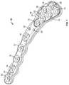
- FIG. 1is a top perspective view of a bone plate according to one embodiment of the present invention.
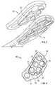
- FIG. 2Ais a top perspective view of a right-oriented aiming block for use with a bone plate according to the present invention.
- FIG. 2Bis a top perspective view of a left-oriented aiming block for use in connection with the bone plate shown in FIG. 1 .
- FIG. 3is a bottom perspective view of the bone plate of FIG. 1 (shown as transparent) with the aiming block of FIG. 2B placed adjacent thereto.
- FIG. 4is a bottom view of the aiming block of FIG. 2B .
- FIG. 5is perspective view of a joystick for use in placement of the aiming blocks of the present invention.
- FIG. 6is a top view of a construct consisting of the bone plate of FIG. 1 , the aiming block of FIG. 2B , and the joystick of FIG. 5 .
- FIG. 7is a cross-sectional view taken on line A-A of FIG. 6 depicting the cooperation among the bone plate, the aiming block, and the joystick.
- FIG. 8is a perspective view of the bone plate of FIG. 1 shown placed on a fractured clavicle bone.
- FIG. 9is a perspective view of the bone plate, aiming block, and joystick construct with cylindrical bodies meant to represent screws, pegs, or other fixation members placed through the holes formed in the aiming block and bone plate.
- FIG. 10is a perspective view of the bone plate of FIG. 1 shown fully attached to a fractured clavicle.
- FIGS. 1-10depict components usable in fixation of human clavicle fractures.
- FIGS. 1-10depict components usable in fixation of human clavicle fractures.
- the various components discussed hereinare directed toward a use in connection with fractured clavicle bones, such components may be modified (if necessary) to have applicability in the repair of fractures in other bones in human or animal bodies.
- Those of ordinary skill in the artwould readily recognize that such components, although discussed in connection with a single purpose, have applicability for other purposes in the orthopedic field.
- Bone plate 10configured for use in fixing a clavicle fracture.
- Bone plate 10includes a plurality of bone screw receiving holes 12 that may facilitate the locking or fixation of such screws to plate 10 and the plate to the bone, elongate holes 14 that may facilitate the reduction of the fracture through the use of compression screws, a recessed area 16 including a plurality of bone screw receiving holes 18 similar to bone screw holes 12 , a plurality of K-wire or suture receiving holes 20 , and a threaded hole 22 situated within recessed area 16 .
- Bone plate 10is preferably constructed of a metallic material such as titanium or the like, and may be designed to be bendable in order to fit certain profiles of certain clavicle bones.
- both holes 12 and 18may be fitted with a rim capable of being deformed by the head of a bone screw, thereby fixing the bone screw to the plate when inserted.
- Holes 12 , 14 and 18can also be designed to receive different types of screws, for instance, any number of those holes can receive locking, non-locking or compression screws, as well as pins or other fixation mechanisms.
- FIGS. 2A and 2Bdepict aiming blocks 30 , which include nearly identical structure, but which are configured for use with two different bone plates 10 .
- block 30 of FIG. 2Bis configured to cooperate with recess 16 of plate 10 , as shown in FIG. 1
- block 30 of FIG. 2Aexhibits an opposite construction suited for a plate oppositely constructed to the one shown in FIG. 1 .
- plate 10may be for use with a clavicle on one side of the body
- an oppositely configured platewould be utilized on the other side of the body.
- block 30is constructed of polymeric or metallic material, such as PEEK, titanium, or stainless steel, but it is to be understood that any suitable type of material may be employed.
- Aiming block 30includes holes 32 which are designed to align with holes 18 when aiming block 30 is placed within recess 16 of plate 10 .
- a K-wire hole 34is provided on aiming block 30 to align with K-wire hole 20 of plate 10 .
- a threaded hole 36is provided on aiming block 30 , which is aligned with threaded hole 22 located within recess 16 of plate 10 .
- aiming block 30also includes an extension 38 designed to cooperate and extend into recess 16 of plate 10 . Extension 38 is preferably sized and shaped so as to fit snugly within recess 16 and prevent aiming block 30 from moving when engaged with plate 10 .
- extension 38best depicts the specific shape of extension 38 , and it is particularly pointed out that the extension is a somewhat discontinuous structure by virtue of the hole structure of block 30 . It is to be understood that extension 38 may be many shapes, as long as such cooperates with recess 16 to keep block 30 aligned with plate 10 . Moreover, extension 38 could be sized so as to form an interference fit or taper lock with recess 16 , or such could include a locking structure designed to cooperate with a locking structure in recess 16 .
- FIG. 5depicts joystick 40 , which is a tool designed for cooperation with both aiming block 30 and plate 10 .
- Joystick 40includes a handle 42 , an elongate shaft 44 , a shoulder section 46 , and a threaded distal tip 48 .
- a section 49extends between shoulder section 46 and distal tip 48 , and includes a diameter that is less than the diameters of both of those flanking sections.
- joystick 40can be constructed of many different materials, including preferably metallic materials such as titanium or stainless steel. It is to be understood that while distal tip 48 is threaded in the preferred embodiment it can include any number of different fixation means, such as taper lock devices, friction fit devices, and ball detent structures.
- joystick 40is designed to thread into both hole 22 of plate 10 and hole 36 of aiming block 30 .
- a surgeonfirst threads distal tip 48 into threaded hole 36 of aiming block 30 .
- joystick 40may be utilized to manipulate and move aiming block 30 into a position within the body and on plate 10 , which is in turn placed on a bone.
- extension 38 of aiming block 30is placed within recess 16 of plate 10 , thereby ensuring proper placement of aiming block 30 on plate 10 , additional threading of joystick 40 , and in particular distal end 48 , can occur. This results in the position best shown in the cross-sectional view of FIG.
- FIGS. 8-10depict proper placement of plate 10 on a fractured clavicle.
- plate 10is first placed over a fracture site on the clavicle, so that the fracture line is spanned by at least a portion of the plate.
- This initial placementmay be aided through the use of K-wires or sutures which can be received in holes 20 of plate 10 .
- K-wires or sutureswhich can be received in holes 20 of plate 10 .
- Any K-wires utilizedmay also be received within hole 34 of aiming block 30 .
- fixation elementsrepresented by cylindrical elements 50 in FIG.
- aiming block 30can be inserted through holes 32 of aiming block 30 and ultimately through holes 18 of plate 10 .
- additional structure provided by aiming block 30and more particularly the extension provided by holes 32 , allows for a more specific placement of screws at a given angle.
- aiming block 30may be utilized to guide a drill, which may be necessary to use prior to inserting screws.
- remaining holes 12 and 14 of plate 10may accept other screws for fixing plate 10 along the clavicle bone.
- FIG. 10A fully fixed plate 10 with screws placed through certain of its holes is shown in FIG. 10 .
- plate 10 , aiming block 30 , and joystick 40may be configured to be utilized in repairing fractures of any bone within the human body.
- each component of the present inventionmay vary depending upon intended use or for aesthetic purposes.
Landscapes
- Health & Medical Sciences (AREA)
- Orthopedic Medicine & Surgery (AREA)
- Surgery (AREA)
- Life Sciences & Earth Sciences (AREA)
- Heart & Thoracic Surgery (AREA)
- Veterinary Medicine (AREA)
- Engineering & Computer Science (AREA)
- Biomedical Technology (AREA)
- Nuclear Medicine, Radiotherapy & Molecular Imaging (AREA)
- Medical Informatics (AREA)
- Molecular Biology (AREA)
- Animal Behavior & Ethology (AREA)
- General Health & Medical Sciences (AREA)
- Public Health (AREA)
- Neurology (AREA)
- Dentistry (AREA)
- Oral & Maxillofacial Surgery (AREA)
- Surgical Instruments (AREA)
Abstract
Description
Claims (22)
Priority Applications (1)
| Application Number | Priority Date | Filing Date | Title |
|---|---|---|---|
| US13/785,121US9050151B2 (en) | 2012-03-06 | 2013-03-05 | Bone plate and aiming block |
Applications Claiming Priority (2)
| Application Number | Priority Date | Filing Date | Title |
|---|---|---|---|
| US201261607242P | 2012-03-06 | 2012-03-06 | |
| US13/785,121US9050151B2 (en) | 2012-03-06 | 2013-03-05 | Bone plate and aiming block |
Publications (2)
| Publication Number | Publication Date |
|---|---|
| US20130238032A1 US20130238032A1 (en) | 2013-09-12 |
| US9050151B2true US9050151B2 (en) | 2015-06-09 |
Family
ID=49114763
Family Applications (1)
| Application Number | Title | Priority Date | Filing Date |
|---|---|---|---|
| US13/785,121Active2033-06-08US9050151B2 (en) | 2012-03-06 | 2013-03-05 | Bone plate and aiming block |
Country Status (1)
| Country | Link |
|---|---|
| US (1) | US9050151B2 (en) |
Cited By (35)
| Publication number | Priority date | Publication date | Assignee | Title |
|---|---|---|---|---|
| US10368928B2 (en) | 2017-03-13 | 2019-08-06 | Globus Medical, Inc. | Bone stabilization systems |
| US10383668B2 (en) | 2016-08-17 | 2019-08-20 | Globus Medical, Inc. | Volar distal radius stabilization system |
| US10420596B2 (en) | 2016-08-17 | 2019-09-24 | Globus Medical, Inc. | Volar distal radius stabilization system |
| US10575884B2 (en) | 2016-08-17 | 2020-03-03 | Globus Medical, Inc. | Fracture plates, systems, and methods |
| US10631903B2 (en) | 2017-03-10 | 2020-04-28 | Globus Medical Inc. | Clavicle fixation system |
| US10687874B2 (en) | 2015-08-27 | 2020-06-23 | Globus Medical, Inc | Proximal humeral stabilization system |
| US10687873B2 (en) | 2016-08-17 | 2020-06-23 | Globus Medical Inc. | Stabilization systems |
| EP3692939A1 (en) | 2019-02-07 | 2020-08-12 | Stryker European Operations Limited | Surgical systems for facilitating tissue treatment |
| US10751098B2 (en) | 2016-08-17 | 2020-08-25 | Globus Medical Inc. | Stabilization systems |
| US10828075B2 (en) | 2015-09-25 | 2020-11-10 | Globus Medical Inc. | Bone fixation devices having a locking feature |
| US10828074B2 (en) | 2015-11-20 | 2020-11-10 | Globus Medical, Inc. | Expandalbe intramedullary systems and methods of using the same |
| US10856920B2 (en) | 2017-09-13 | 2020-12-08 | Globus Medical Inc. | Bone stabilization systems |
| US10905477B2 (en) | 2017-03-13 | 2021-02-02 | Globus Medical, Inc. | Bone stabilization systems |
| US11065042B2 (en) | 2015-02-04 | 2021-07-20 | Flower Orthopedics Corporation | Bone plate and guide block and attachment mechanism thereof |
| US11071570B2 (en)* | 2018-03-02 | 2021-07-27 | Globus Medical, Inc. | Distal tibial plating system |
| US11076898B2 (en) | 2015-08-27 | 2021-08-03 | Globus Medical, Inc. | Proximal humeral stabilization system |
| US11096730B2 (en)* | 2017-09-13 | 2021-08-24 | Globus Medical Inc. | Bone stabilization systems |
| US11129627B2 (en) | 2019-10-30 | 2021-09-28 | Globus Medical, Inc. | Method and apparatus for inserting a bone plate |
| US11141172B2 (en) | 2018-04-11 | 2021-10-12 | Globus Medical, Inc. | Method and apparatus for locking a drill guide in a polyaxial hole |
| US11141204B2 (en) | 2016-08-17 | 2021-10-12 | Globus Medical Inc. | Wrist stabilization systems |
| US11197701B2 (en) | 2016-08-17 | 2021-12-14 | Globus Medical, Inc. | Stabilization systems |
| US11197682B2 (en) | 2015-08-27 | 2021-12-14 | Globus Medical, Inc. | Proximal humeral stabilization system |
| US11197704B2 (en) | 2016-04-19 | 2021-12-14 | Globus Medical, Inc. | Implantable compression screws |
| US11202663B2 (en) | 2019-02-13 | 2021-12-21 | Globus Medical, Inc. | Proximal humeral stabilization systems and methods thereof |
| US11213327B2 (en) | 2016-08-17 | 2022-01-04 | Globus Medical, Inc. | Fracture plates, systems, and methods |
| US11224468B2 (en) | 2018-03-02 | 2022-01-18 | Globus Medical, Inc. | Distal tibial plating system |
| US20220039847A1 (en)* | 2017-09-13 | 2022-02-10 | Globus Medical, Inc. | Bone stabilization systems |
| US11284920B2 (en) | 2016-03-02 | 2022-03-29 | Globus Medical Inc. | Fixators for bone stabilization and associated systems and methods |
| US11331128B2 (en) | 2016-08-17 | 2022-05-17 | Globus Medical Inc. | Distal radius stabilization system |
| US11426220B2 (en)* | 2017-10-11 | 2022-08-30 | Howmedica Osteonics Corp. | Humeral fixation plate guides |
| US11432857B2 (en) | 2016-08-17 | 2022-09-06 | Globus Medical, Inc. | Stabilization systems |
| US11723647B2 (en) | 2019-12-17 | 2023-08-15 | Globus Medical, Inc. | Syndesmosis fixation assembly |
| US12042200B2 (en) | 2016-09-22 | 2024-07-23 | Globus Medical, Inc. | Systems and methods for intramedullary nail implantation |
| US12064150B2 (en) | 2022-01-19 | 2024-08-20 | Globus Medical Inc. | System and method for treating bone fractures |
| US12185995B2 (en) | 2019-10-09 | 2025-01-07 | Globus Medical, Inc. | Bone stabilization systems |
Families Citing this family (11)
| Publication number | Priority date | Publication date | Assignee | Title |
|---|---|---|---|---|
| US9050151B2 (en)* | 2012-03-06 | 2015-06-09 | Stryker Trauma Sa | Bone plate and aiming block |
| EP3065656B1 (en) | 2013-11-05 | 2020-12-23 | Arthrex, Inc. | Tplo plate with suture holes for rotational stability |
| US10226288B2 (en)* | 2014-11-10 | 2019-03-12 | Biomedtrix, Llc | Osteotomy plate for long bones |
| US10245088B2 (en) | 2015-01-07 | 2019-04-02 | Treace Medical Concepts, Inc. | Bone plating system and method |
| WO2016134160A1 (en) | 2015-02-18 | 2016-08-25 | Treace Medical Concepts, Inc. | Bone plating kit for foot and ankle applications |
| US11583323B2 (en) | 2018-07-12 | 2023-02-21 | Treace Medical Concepts, Inc. | Multi-diameter bone pin for installing and aligning bone fixation plate while minimizing bone damage |
| US11890039B1 (en) | 2019-09-13 | 2024-02-06 | Treace Medical Concepts, Inc. | Multi-diameter K-wire for orthopedic applications |
| WO2021087024A1 (en)* | 2019-10-29 | 2021-05-06 | Smith & Nephew, Inc. | Periprosthetic bone plate systems |
| US11395686B2 (en)* | 2020-04-20 | 2022-07-26 | Khay-Yong Saw | Bone fixation plate and method of using thereof |
| EP4342398A3 (en) | 2020-05-19 | 2024-05-29 | Smith & Nephew, Inc. | Periprosthetic bone plate |
| US20220296288A1 (en)* | 2021-03-22 | 2022-09-22 | Acumed Llc | Anterolateral clavicle fracture fixation plate |
Citations (73)
| Publication number | Priority date | Publication date | Assignee | Title |
|---|---|---|---|---|
| US38684A (en) | 1863-05-26 | Improvement in cylinder-molds for making paper | ||
| US2494229A (en) | 1946-07-08 | 1950-01-10 | John G Collison | Bone surgery |
| US2935905A (en) | 1956-12-10 | 1960-05-10 | Winslow Product Engineering Co | Collet foot attachment for pneumatic power drill |
| US4788970A (en) | 1986-04-01 | 1988-12-06 | Huta Baildon | Drill setting guide for drilling holes in bones |
| US5147367A (en) | 1991-02-22 | 1992-09-15 | Ellis Alfred B | Drill pin guide and method for orthopedic surgery |
| US5417694A (en) | 1993-11-08 | 1995-05-23 | Smith & Nephew Richards Inc. | Distal femoral cutting guide apparatus with anterior or posterior referencing for use in knee joint replacement surgery |
| US5423826A (en) | 1993-02-05 | 1995-06-13 | Danek Medical, Inc. | Anterior cervical plate holder/drill guide and method of use |
| US5507801A (en) | 1990-06-06 | 1996-04-16 | Synthes (U.S.A.) | Compression drill guide |
| US5851207A (en) | 1997-07-01 | 1998-12-22 | Synthes (U.S.A.) | Freely separable surgical drill guide and plate |
| US5897557A (en) | 1998-03-13 | 1999-04-27 | Chin; Albert K. | Bone fracture reinforcement structure and method |
| US5935128A (en) | 1997-04-18 | 1999-08-10 | Bristol-Myers Squibb Co. | Orthopaedic template system including a joint locator |
| US5993449A (en) | 1995-11-30 | 1999-11-30 | Synthes (Usa) | Bone-fixing device |
| US6007535A (en) | 1996-01-03 | 1999-12-28 | John M. Rayhack | Multi-plane bone distraction system |
| US6235034B1 (en)* | 1997-10-24 | 2001-05-22 | Robert S. Bray | Bone plate and bone screw guide mechanism |
| WO2001082804A1 (en) | 2000-04-28 | 2001-11-08 | Synthes Ag Chur | Dual drill guide for a locking bone plate |
| US6342057B1 (en) | 2000-04-28 | 2002-01-29 | Synthes (Usa) | Remotely aligned surgical drill guide |
| US6358250B1 (en) | 2000-02-01 | 2002-03-19 | Hand Innovations, Inc. | Volar fixation system |
| US6440135B2 (en) | 2000-02-01 | 2002-08-27 | Hand Innovations, Inc. | Volar fixation system with articulating stabilization pegs |
| US20030040748A1 (en) | 2001-08-24 | 2003-02-27 | Aikins Jerry L. | Blade plate and instruments |
| US20030153918A1 (en) | 2002-02-14 | 2003-08-14 | Putnam Matthew D. | Volar fixation plate |
| US6692503B2 (en) | 1999-10-13 | 2004-02-17 | Sdgi Holdings, Inc | System and method for securing a plate to the spinal column |
| US6706046B2 (en) | 2000-02-01 | 2004-03-16 | Hand Innovations, Inc. | Intramedullary fixation device for metaphyseal long bone fractures and methods of using the same |
| US20040102788A1 (en) | 2002-11-19 | 2004-05-27 | Huebner Randall J. | Guide system for bone-repair devices |
| US6755831B2 (en) | 2001-11-30 | 2004-06-29 | Regents Of The University Of Minnesota | Wrist surgery devices and techniques |
| US20040204717A1 (en) | 2003-04-09 | 2004-10-14 | Jonathan Fanger | Guide for spinal tools, implants, and devices |
| US20040204716A1 (en) | 2003-04-09 | 2004-10-14 | Jonathan Fanger | Drill guide with alignment feature |
| US20050015092A1 (en) | 2003-07-16 | 2005-01-20 | Rathbun David S. | Plating system with multiple function drill guide |
| US20050049594A1 (en) | 2001-04-20 | 2005-03-03 | Wack Michael A. | Dual locking plate and associated method |
| US6866665B2 (en) | 2003-03-27 | 2005-03-15 | Hand Innovations, Llc | Bone fracture fixation system with subchondral and articular surface support |
| US20050085818A1 (en)* | 2003-10-17 | 2005-04-21 | Huebner Randall J. | Systems for distal radius fixation |
| US20050137606A1 (en) | 2003-08-13 | 2005-06-23 | Binder Lawrence J.Jr. | Quick-release drill guide assembly for bone plate |
| US20050159747A1 (en)* | 2000-02-01 | 2005-07-21 | Orbay Jorge L. | Volar fixation system including guide |
| US6926720B2 (en) | 2003-10-15 | 2005-08-09 | Hand Innovations, Llc | Jig assembly for implantation of a fracture fixation device |
| WO2005092225A1 (en) | 2004-03-11 | 2005-10-06 | Synthes Gmbh | Resetting tool |
| US20050228398A1 (en) | 2004-04-12 | 2005-10-13 | Rathbun David S | Free hand drill guide |
| US20050234472A1 (en) | 2004-04-19 | 2005-10-20 | Huebner Randall J | Placement of fasteners into bone |
| US20050234458A1 (en) | 2004-04-19 | 2005-10-20 | Huebner Randall J | Expanded stabilization of bones |
| US20060095044A1 (en) | 2004-11-03 | 2006-05-04 | Grady Mark P Jr | Aiming arm for bone plates |
| US20060116679A1 (en) | 2004-11-30 | 2006-06-01 | Stryker Trauma Sa | Bone plating implants, instruments and methods |
| US20060149257A1 (en) | 2002-05-30 | 2006-07-06 | Orbay Jorge L | Fracture fixation device |
| US20060161168A1 (en) | 2003-07-14 | 2006-07-20 | Romano Matthys | Targeting device |
| US20060161158A1 (en) | 2004-12-14 | 2006-07-20 | Orbay Jorge L | Bone fracture fixation plate shaping system |
| US7081119B2 (en) | 2003-08-01 | 2006-07-25 | Hfsc Company | Drill guide assembly for a bone fixation device |
| US20060173458A1 (en) | 2004-10-07 | 2006-08-03 | Micah Forstein | Bone fracture fixation system |
| WO2006081483A1 (en) | 2005-01-28 | 2006-08-03 | Depuy Products, Inc. | Nail plate system |
| US20060229618A1 (en)* | 2005-03-16 | 2006-10-12 | Dube Michael A | Anterior lumbar lag plate |
| US20070167953A1 (en)* | 2006-01-17 | 2007-07-19 | Stryker Trauma Gmbh | Targeting device for orthopedic implants |
| US20070173836A1 (en) | 2006-01-17 | 2007-07-26 | Stryker Trauma Gmbh | Targeting device for bone implant |
| US20070173839A1 (en)* | 2006-01-10 | 2007-07-26 | Running Donald E | Fracture fixation plate with cover sheath |
| US20070173843A1 (en) | 2005-12-22 | 2007-07-26 | Matityahu Amir M | Drug delivering bone plate and method and targeting device for use therewith |
| US7250053B2 (en) | 2003-03-27 | 2007-07-31 | Depuy Products, Inc. | Low profile distal radius fracture fixation plate |
| US20070191855A1 (en) | 2006-01-27 | 2007-08-16 | Orbay Jorge L | Fracture fixation device and implantation jig therefor |
| US7282053B2 (en) | 2003-03-27 | 2007-10-16 | Depuy Products, Inc. | Method of using fracture fixation plate for performing osteotomy |
| US7294130B2 (en) | 2003-03-27 | 2007-11-13 | Depuy Products, Inc. | Distal radius fracture fixation plate having K-wire hole structured to fix a K-wire in one dimension relative to the plate |
| US20080183172A1 (en) | 2007-01-26 | 2008-07-31 | Zimmer Technology, Inc. | Retention feature for plate guides |
| US20090088768A1 (en)* | 2007-09-27 | 2009-04-02 | Depuy Products, Inc. | Apparatus for measuring an angle of a guide wire relative to a bone |
| US20090157086A1 (en) | 2007-12-17 | 2009-06-18 | Stryker Leibinger Gmbh & Co. Kg | Bone plate instrument and method |
| US20090228047A1 (en)* | 2008-03-07 | 2009-09-10 | Guillaume Derouet | Device for reducing a fracture, in particular a distal radius fracture |
| US7625378B2 (en) | 2002-09-30 | 2009-12-01 | Warsaw Orthopedic, Inc. | Devices and methods for securing a bone plate to a bony segment |
| US7736380B2 (en) | 2004-12-21 | 2010-06-15 | Rhausler, Inc. | Cervical plate system |
| US7740634B2 (en) | 2006-03-20 | 2010-06-22 | Depuy Products, Inc. | Method of bone plate shaping |
| US20100179599A1 (en)* | 2009-01-12 | 2010-07-15 | Guillaume Derouet | Device for reducing a bone fracture, in particular a fracture at the bone epiphyses |
| US7909848B2 (en) | 2003-06-27 | 2011-03-22 | Depuy Spine, Inc. | Tissue retractor and guide device |
| US7935126B2 (en) | 2006-03-20 | 2011-05-03 | Depuy Products, Inc. | Bone plate shaping system |
| US20110106086A1 (en)* | 2008-04-03 | 2011-05-05 | Austofix Group Limited | Tool jig for bone implant assembly |
| US20110172669A1 (en) | 2004-12-14 | 2011-07-14 | Castaneda Javier E | Bone Plate With Pre-Assembled Drill Guide Tips |
| US20110313422A1 (en) | 2010-05-25 | 2011-12-22 | Stryker Trauma Sa | Implant for bone fixation |
| US20120078252A1 (en)* | 2010-09-27 | 2012-03-29 | Huebner Randall J | Targeting guide with a radiopaque marker to facilitate positioning a bone plate on bone |
| US20120191104A1 (en)* | 2011-01-21 | 2012-07-26 | Jost Reto | Depth Probe for the Humeral Head |
| US8231625B2 (en)* | 2008-09-03 | 2012-07-31 | The Cleveland Clinic Foundation | Modular bone fixation device for treatment of fractures and related methods |
| US20120253347A1 (en)* | 2011-04-04 | 2012-10-04 | Murashko Jr Alexander | Bone plate aiming block |
| US20130238032A1 (en)* | 2012-03-06 | 2013-09-12 | Stryker Trauma Sa | Bone plate and aiming block |
| US8641741B2 (en)* | 2010-10-13 | 2014-02-04 | Stryker Leibinger Gmbh & Co. Kg | Bone plate aiming block |
- 2013
- 2013-03-05USUS13/785,121patent/US9050151B2/enactiveActive
Patent Citations (99)
| Publication number | Priority date | Publication date | Assignee | Title |
|---|---|---|---|---|
| US38684A (en) | 1863-05-26 | Improvement in cylinder-molds for making paper | ||
| US2494229A (en) | 1946-07-08 | 1950-01-10 | John G Collison | Bone surgery |
| US2935905A (en) | 1956-12-10 | 1960-05-10 | Winslow Product Engineering Co | Collet foot attachment for pneumatic power drill |
| US4788970A (en) | 1986-04-01 | 1988-12-06 | Huta Baildon | Drill setting guide for drilling holes in bones |
| US5507801A (en) | 1990-06-06 | 1996-04-16 | Synthes (U.S.A.) | Compression drill guide |
| US5147367A (en) | 1991-02-22 | 1992-09-15 | Ellis Alfred B | Drill pin guide and method for orthopedic surgery |
| US5423826A (en) | 1993-02-05 | 1995-06-13 | Danek Medical, Inc. | Anterior cervical plate holder/drill guide and method of use |
| US5417694A (en) | 1993-11-08 | 1995-05-23 | Smith & Nephew Richards Inc. | Distal femoral cutting guide apparatus with anterior or posterior referencing for use in knee joint replacement surgery |
| US5993449A (en) | 1995-11-30 | 1999-11-30 | Synthes (Usa) | Bone-fixing device |
| US6007535A (en) | 1996-01-03 | 1999-12-28 | John M. Rayhack | Multi-plane bone distraction system |
| US5935128A (en) | 1997-04-18 | 1999-08-10 | Bristol-Myers Squibb Co. | Orthopaedic template system including a joint locator |
| EP0993275A1 (en) | 1997-07-01 | 2000-04-19 | Synthes Ag Chur | Freely separable surgical drill guide and plate |
| US5851207A (en) | 1997-07-01 | 1998-12-22 | Synthes (U.S.A.) | Freely separable surgical drill guide and plate |
| USRE38684E1 (en) | 1997-07-01 | 2005-01-04 | Synthes Ag Chur | Freely separable surgical drill guide and plate |
| US6235034B1 (en)* | 1997-10-24 | 2001-05-22 | Robert S. Bray | Bone plate and bone screw guide mechanism |
| US5897557A (en) | 1998-03-13 | 1999-04-27 | Chin; Albert K. | Bone fracture reinforcement structure and method |
| US6692503B2 (en) | 1999-10-13 | 2004-02-17 | Sdgi Holdings, Inc | System and method for securing a plate to the spinal column |
| US6364882B1 (en) | 2000-02-01 | 2002-04-02 | Hand Innovations, Inc. | Volar fixation system |
| US6440135B2 (en) | 2000-02-01 | 2002-08-27 | Hand Innovations, Inc. | Volar fixation system with articulating stabilization pegs |
| US20100268283A1 (en)* | 2000-02-01 | 2010-10-21 | Orbay Jorge L | Volar Fixation System And Methods of Using The Same |
| US6358250B1 (en) | 2000-02-01 | 2002-03-19 | Hand Innovations, Inc. | Volar fixation system |
| US6706046B2 (en) | 2000-02-01 | 2004-03-16 | Hand Innovations, Inc. | Intramedullary fixation device for metaphyseal long bone fractures and methods of using the same |
| US20050159747A1 (en)* | 2000-02-01 | 2005-07-21 | Orbay Jorge L. | Volar fixation system including guide |
| US6342057B1 (en) | 2000-04-28 | 2002-01-29 | Synthes (Usa) | Remotely aligned surgical drill guide |
| US6379364B1 (en) | 2000-04-28 | 2002-04-30 | Synthes (Usa) | Dual drill guide for a locking bone plate |
| WO2001082804A1 (en) | 2000-04-28 | 2001-11-08 | Synthes Ag Chur | Dual drill guide for a locking bone plate |
| US20050049594A1 (en) | 2001-04-20 | 2005-03-03 | Wack Michael A. | Dual locking plate and associated method |
| US20030040748A1 (en) | 2001-08-24 | 2003-02-27 | Aikins Jerry L. | Blade plate and instruments |
| US6755831B2 (en) | 2001-11-30 | 2004-06-29 | Regents Of The University Of Minnesota | Wrist surgery devices and techniques |
| US20030153918A1 (en) | 2002-02-14 | 2003-08-14 | Putnam Matthew D. | Volar fixation plate |
| US20060149257A1 (en) | 2002-05-30 | 2006-07-06 | Orbay Jorge L | Fracture fixation device |
| US7625378B2 (en) | 2002-09-30 | 2009-12-01 | Warsaw Orthopedic, Inc. | Devices and methods for securing a bone plate to a bony segment |
| US7153309B2 (en) | 2002-11-19 | 2006-12-26 | Acumed Llc | Guide system for bone-repair devices |
| US20040102788A1 (en) | 2002-11-19 | 2004-05-27 | Huebner Randall J. | Guide system for bone-repair devices |
| US7282053B2 (en) | 2003-03-27 | 2007-10-16 | Depuy Products, Inc. | Method of using fracture fixation plate for performing osteotomy |
| US6866665B2 (en) | 2003-03-27 | 2005-03-15 | Hand Innovations, Llc | Bone fracture fixation system with subchondral and articular surface support |
| US7294130B2 (en) | 2003-03-27 | 2007-11-13 | Depuy Products, Inc. | Distal radius fracture fixation plate having K-wire hole structured to fix a K-wire in one dimension relative to the plate |
| US7250053B2 (en) | 2003-03-27 | 2007-07-31 | Depuy Products, Inc. | Low profile distal radius fracture fixation plate |
| US20040204717A1 (en) | 2003-04-09 | 2004-10-14 | Jonathan Fanger | Guide for spinal tools, implants, and devices |
| US7935123B2 (en) | 2003-04-09 | 2011-05-03 | Depuy Acromed, Inc. | Drill guide with alignment feature |
| US20040204716A1 (en) | 2003-04-09 | 2004-10-14 | Jonathan Fanger | Drill guide with alignment feature |
| US7909848B2 (en) | 2003-06-27 | 2011-03-22 | Depuy Spine, Inc. | Tissue retractor and guide device |
| US20060161168A1 (en) | 2003-07-14 | 2006-07-20 | Romano Matthys | Targeting device |
| US7731721B2 (en) | 2003-07-16 | 2010-06-08 | Synthes Usa, Llc | Plating system with multiple function drill guide |
| US20050015093A1 (en) | 2003-07-16 | 2005-01-20 | Suh Sean S. | Plating system with compression drill guide |
| US20050015092A1 (en) | 2003-07-16 | 2005-01-20 | Rathbun David S. | Plating system with multiple function drill guide |
| US7081119B2 (en) | 2003-08-01 | 2006-07-25 | Hfsc Company | Drill guide assembly for a bone fixation device |
| US20050137606A1 (en) | 2003-08-13 | 2005-06-23 | Binder Lawrence J.Jr. | Quick-release drill guide assembly for bone plate |
| US6926720B2 (en) | 2003-10-15 | 2005-08-09 | Hand Innovations, Llc | Jig assembly for implantation of a fracture fixation device |
| US20050085818A1 (en)* | 2003-10-17 | 2005-04-21 | Huebner Randall J. | Systems for distal radius fixation |
| WO2005092225A1 (en) | 2004-03-11 | 2005-10-06 | Synthes Gmbh | Resetting tool |
| US20120041447A1 (en) | 2004-03-11 | 2012-02-16 | Stefan Schwer | Resetting Tool |
| US20060100637A1 (en) | 2004-04-12 | 2006-05-11 | Rathbun David S | Drill-tap-screw drill guide |
| US20050228398A1 (en) | 2004-04-12 | 2005-10-13 | Rathbun David S | Free hand drill guide |
| US20050234458A1 (en) | 2004-04-19 | 2005-10-20 | Huebner Randall J | Expanded stabilization of bones |
| US7578825B2 (en)* | 2004-04-19 | 2009-08-25 | Acumed Llc | Placement of fasteners into bone |
| US20050234472A1 (en) | 2004-04-19 | 2005-10-20 | Huebner Randall J | Placement of fasteners into bone |
| US20060173458A1 (en) | 2004-10-07 | 2006-08-03 | Micah Forstein | Bone fracture fixation system |
| US20090312760A1 (en) | 2004-10-07 | 2009-12-17 | Zimmer, Inc. | Bone fracture fixation system |
| US20060095044A1 (en) | 2004-11-03 | 2006-05-04 | Grady Mark P Jr | Aiming arm for bone plates |
| US20060116679A1 (en) | 2004-11-30 | 2006-06-01 | Stryker Trauma Sa | Bone plating implants, instruments and methods |
| US7648508B2 (en) | 2004-11-30 | 2010-01-19 | Stryker Trauma S.A. | Bone plating implants, instruments and methods |
| US7771433B2 (en) | 2004-12-14 | 2010-08-10 | Depuy Products, Inc. | Bone fracture fixation plate shaping system |
| US20060161158A1 (en) | 2004-12-14 | 2006-07-20 | Orbay Jorge L | Bone fracture fixation plate shaping system |
| US20110172669A1 (en) | 2004-12-14 | 2011-07-14 | Castaneda Javier E | Bone Plate With Pre-Assembled Drill Guide Tips |
| US7736380B2 (en) | 2004-12-21 | 2010-06-15 | Rhausler, Inc. | Cervical plate system |
| US20060200157A1 (en) | 2005-01-28 | 2006-09-07 | Orbay Jorge L | Nail Plate and Jig Therefor |
| US20060189996A1 (en) | 2005-01-28 | 2006-08-24 | Orbay Jorge L | Nail plate and implantation jig therefor |
| WO2006081483A1 (en) | 2005-01-28 | 2006-08-03 | Depuy Products, Inc. | Nail plate system |
| US20060229618A1 (en)* | 2005-03-16 | 2006-10-12 | Dube Michael A | Anterior lumbar lag plate |
| US8052729B2 (en)* | 2005-03-16 | 2011-11-08 | Stryker Spine | Anterior lumbar lag plate |
| US20070173843A1 (en) | 2005-12-22 | 2007-07-26 | Matityahu Amir M | Drug delivering bone plate and method and targeting device for use therewith |
| US8100952B2 (en) | 2005-12-22 | 2012-01-24 | Anthem Orthopaedics Llc | Drug delivering bone plate and method and targeting device for use therewith |
| US8029551B2 (en)* | 2006-01-10 | 2011-10-04 | Running Donald E | Fracture fixation plate with cover sheath |
| US20070173839A1 (en)* | 2006-01-10 | 2007-07-26 | Running Donald E | Fracture fixation plate with cover sheath |
| US20070167953A1 (en)* | 2006-01-17 | 2007-07-19 | Stryker Trauma Gmbh | Targeting device for orthopedic implants |
| US20070173836A1 (en) | 2006-01-17 | 2007-07-26 | Stryker Trauma Gmbh | Targeting device for bone implant |
| US20070191855A1 (en) | 2006-01-27 | 2007-08-16 | Orbay Jorge L | Fracture fixation device and implantation jig therefor |
| US7740634B2 (en) | 2006-03-20 | 2010-06-22 | Depuy Products, Inc. | Method of bone plate shaping |
| US7935126B2 (en) | 2006-03-20 | 2011-05-03 | Depuy Products, Inc. | Bone plate shaping system |
| US20080183172A1 (en) | 2007-01-26 | 2008-07-31 | Zimmer Technology, Inc. | Retention feature for plate guides |
| US20090088768A1 (en)* | 2007-09-27 | 2009-04-02 | Depuy Products, Inc. | Apparatus for measuring an angle of a guide wire relative to a bone |
| US20090157086A1 (en) | 2007-12-17 | 2009-06-18 | Stryker Leibinger Gmbh & Co. Kg | Bone plate instrument and method |
| US8162950B2 (en)* | 2007-12-17 | 2012-04-24 | Stryker Leibinger Gmbh & Co. Kg | Bone plate instrument and method |
| JP2009178543A (en) | 2007-12-17 | 2009-08-13 | Stryker Leibinger Gmbh & Co Kg | Bone plate instrument and method |
| US20090228047A1 (en)* | 2008-03-07 | 2009-09-10 | Guillaume Derouet | Device for reducing a fracture, in particular a distal radius fracture |
| US20110106086A1 (en)* | 2008-04-03 | 2011-05-05 | Austofix Group Limited | Tool jig for bone implant assembly |
| US8231625B2 (en)* | 2008-09-03 | 2012-07-31 | The Cleveland Clinic Foundation | Modular bone fixation device for treatment of fractures and related methods |
| US20100179599A1 (en)* | 2009-01-12 | 2010-07-15 | Guillaume Derouet | Device for reducing a bone fracture, in particular a fracture at the bone epiphyses |
| US20110313422A1 (en) | 2010-05-25 | 2011-12-22 | Stryker Trauma Sa | Implant for bone fixation |
| US20120078312A1 (en)* | 2010-09-27 | 2012-03-29 | Federspiel Joshua P | Handle assembly having a radiopaque region to facilitate positioning a bone plate on bone |
| US20120078252A1 (en)* | 2010-09-27 | 2012-03-29 | Huebner Randall J | Targeting guide with a radiopaque marker to facilitate positioning a bone plate on bone |
| US8523919B2 (en)* | 2010-09-27 | 2013-09-03 | Acumed Llc | Targeting guide with a radiopaque marker to facilitate positioning a bone plate on bone |
| US8652180B2 (en)* | 2010-09-27 | 2014-02-18 | Acumed Llc | Handle assembly having a radiopaque region to facilitate positioning a bone plate on bone |
| US8641741B2 (en)* | 2010-10-13 | 2014-02-04 | Stryker Leibinger Gmbh & Co. Kg | Bone plate aiming block |
| US20120191104A1 (en)* | 2011-01-21 | 2012-07-26 | Jost Reto | Depth Probe for the Humeral Head |
| US20120253347A1 (en)* | 2011-04-04 | 2012-10-04 | Murashko Jr Alexander | Bone plate aiming block |
| US8523862B2 (en)* | 2011-04-04 | 2013-09-03 | Stryker Leibinger Gmbh & Co. Kg | Bone plate aiming block |
| US20130238032A1 (en)* | 2012-03-06 | 2013-09-12 | Stryker Trauma Sa | Bone plate and aiming block |
Non-Patent Citations (1)
| Title |
|---|
| Partial European Search Report, EP 07 02 4429. |
Cited By (82)
| Publication number | Priority date | Publication date | Assignee | Title |
|---|---|---|---|---|
| US11065042B2 (en) | 2015-02-04 | 2021-07-20 | Flower Orthopedics Corporation | Bone plate and guide block and attachment mechanism thereof |
| US11931083B2 (en) | 2015-08-27 | 2024-03-19 | Globus Medical Inc. | Proximal humeral stabilization system |
| US11617606B2 (en) | 2015-08-27 | 2023-04-04 | Globus Medical Inc. | Proximal humeral stabilization system |
| US11076898B2 (en) | 2015-08-27 | 2021-08-03 | Globus Medical, Inc. | Proximal humeral stabilization system |
| US12059160B2 (en) | 2015-08-27 | 2024-08-13 | Globus Medical Inc. | Proximal humeral stabilization system |
| US10687874B2 (en) | 2015-08-27 | 2020-06-23 | Globus Medical, Inc | Proximal humeral stabilization system |
| US11197682B2 (en) | 2015-08-27 | 2021-12-14 | Globus Medical, Inc. | Proximal humeral stabilization system |
| US10828075B2 (en) | 2015-09-25 | 2020-11-10 | Globus Medical Inc. | Bone fixation devices having a locking feature |
| US10828074B2 (en) | 2015-11-20 | 2020-11-10 | Globus Medical, Inc. | Expandalbe intramedullary systems and methods of using the same |
| US12042180B2 (en) | 2016-03-02 | 2024-07-23 | Globus Medical Inc. | Fixators for bone stabilization and associated systems and methods |
| US11284920B2 (en) | 2016-03-02 | 2022-03-29 | Globus Medical Inc. | Fixators for bone stabilization and associated systems and methods |
| US11197704B2 (en) | 2016-04-19 | 2021-12-14 | Globus Medical, Inc. | Implantable compression screws |
| US11980404B2 (en) | 2016-04-19 | 2024-05-14 | Globus Medical, Inc. | Implantable compression screws |
| US11331128B2 (en) | 2016-08-17 | 2022-05-17 | Globus Medical Inc. | Distal radius stabilization system |
| US11197701B2 (en) | 2016-08-17 | 2021-12-14 | Globus Medical, Inc. | Stabilization systems |
| US11896271B2 (en) | 2016-08-17 | 2024-02-13 | Globus Medical, Inc. | Stabilization systems |
| US12295626B2 (en) | 2016-08-17 | 2025-05-13 | Globus Medical, Inc. | Stabilization systems |
| US10383668B2 (en) | 2016-08-17 | 2019-08-20 | Globus Medical, Inc. | Volar distal radius stabilization system |
| US12256965B2 (en) | 2016-08-17 | 2025-03-25 | Global Medical, Inc. | Wrist stabilization systems |
| US12245799B2 (en) | 2016-08-17 | 2025-03-11 | Globus Medical, Inc. | Fracture plates, systems, and methods |
| US11957389B2 (en) | 2016-08-17 | 2024-04-16 | Globus Medical, Inc. | Systems and methods for bone fixation anchor, plate, and spacer devices |
| US11141204B2 (en) | 2016-08-17 | 2021-10-12 | Globus Medical Inc. | Wrist stabilization systems |
| US10420596B2 (en) | 2016-08-17 | 2019-09-24 | Globus Medical, Inc. | Volar distal radius stabilization system |
| US11147599B2 (en) | 2016-08-17 | 2021-10-19 | Globus Medical Inc. | Systems and methods for bone fixation anchor, plate, and spacer devices |
| US11160590B2 (en) | 2016-08-17 | 2021-11-02 | Globus Medical, Inc. | Volar distal radius stabilization system |
| US12295627B2 (en) | 2016-08-17 | 2025-05-13 | Globus Medical, Inc. | Stabilization systems |
| US10575884B2 (en) | 2016-08-17 | 2020-03-03 | Globus Medical, Inc. | Fracture plates, systems, and methods |
| US10751098B2 (en) | 2016-08-17 | 2020-08-25 | Globus Medical Inc. | Stabilization systems |
| US12408958B2 (en) | 2016-08-17 | 2025-09-09 | Globus Medical, Inc. | Distal radius stabilization system |
| US10687873B2 (en) | 2016-08-17 | 2020-06-23 | Globus Medical Inc. | Stabilization systems |
| US11213327B2 (en) | 2016-08-17 | 2022-01-04 | Globus Medical, Inc. | Fracture plates, systems, and methods |
| US11432857B2 (en) | 2016-08-17 | 2022-09-06 | Globus Medical, Inc. | Stabilization systems |
| US12004790B2 (en) | 2016-08-17 | 2024-06-11 | Globus Medical, Inc | Volar distal radius stabilization system |
| US11992252B2 (en) | 2016-08-17 | 2024-05-28 | Globus Medical, Inc. | Distal radius stabilization system |
| US11278332B2 (en) | 2016-08-17 | 2022-03-22 | Globus Medical, Inc. | Distal radius stabilization system |
| US11612422B2 (en) | 2016-08-17 | 2023-03-28 | Globus Medical Inc. | Stabilization systems |
| US11832857B2 (en) | 2016-08-17 | 2023-12-05 | Globus Medical, Inc. | Fracture plates, systems, and methods |
| US11986225B2 (en) | 2016-08-17 | 2024-05-21 | Globus Medical Inc. | Distal radius stabilization system |
| US12042200B2 (en) | 2016-09-22 | 2024-07-23 | Globus Medical, Inc. | Systems and methods for intramedullary nail implantation |
| US11357554B2 (en) | 2017-03-10 | 2022-06-14 | Globus Medical Inc. | Clavicle fixation system |
| US10631903B2 (en) | 2017-03-10 | 2020-04-28 | Globus Medical Inc. | Clavicle fixation system |
| US12161372B2 (en) | 2017-03-10 | 2024-12-10 | Globus Medical, Inc. | Clavicle fixation system |
| US10881438B2 (en) | 2017-03-10 | 2021-01-05 | Globus Medical, Inc. | Clavicle fixation system |
| US11857229B2 (en) | 2017-03-10 | 2024-01-02 | Globus Medical, Inc. | Clavicle fixation system |
| US11058467B2 (en) | 2017-03-13 | 2021-07-13 | Globus Medical, Inc. | Bone stabilization systems |
| US10368928B2 (en) | 2017-03-13 | 2019-08-06 | Globus Medical, Inc. | Bone stabilization systems |
| US12089883B2 (en) | 2017-03-13 | 2024-09-17 | Globus Medical, Inc. | Bone stabilization systems |
| US10905477B2 (en) | 2017-03-13 | 2021-02-02 | Globus Medical, Inc. | Bone stabilization systems |
| US11607254B2 (en) | 2017-09-13 | 2023-03-21 | Globus Medical, Inc. | Bone stabilization systems |
| US12042194B2 (en) | 2017-09-13 | 2024-07-23 | Globus Medical Inc. | Bone stabilization systems |
| US11871970B2 (en)* | 2017-09-13 | 2024-01-16 | Globus Medical, Inc | Bone stabilization systems |
| US12390254B2 (en) | 2017-09-13 | 2025-08-19 | Globus Medical Inc. | Bone stabilization systems |
| US12318122B2 (en)* | 2017-09-13 | 2025-06-03 | Globus Medical, Inc. | Bone stabilization systems |
| US10856920B2 (en) | 2017-09-13 | 2020-12-08 | Globus Medical Inc. | Bone stabilization systems |
| US12279795B2 (en) | 2017-09-13 | 2025-04-22 | Globus Medical, Inc. | Bone stabilization systems |
| US11096730B2 (en)* | 2017-09-13 | 2021-08-24 | Globus Medical Inc. | Bone stabilization systems |
| US20220039847A1 (en)* | 2017-09-13 | 2022-02-10 | Globus Medical, Inc. | Bone stabilization systems |
| US20210353339A1 (en)* | 2017-09-13 | 2021-11-18 | Globus Medical, Inc. | Bone stabilization systems |
| US11426220B2 (en)* | 2017-10-11 | 2022-08-30 | Howmedica Osteonics Corp. | Humeral fixation plate guides |
| US12137953B2 (en) | 2017-10-11 | 2024-11-12 | Howmedica Osteonics Corp. | Humeral fixation plates |
| US12102363B2 (en)* | 2018-03-02 | 2024-10-01 | Globus Medical Inc. | Distal tibial plating system |
| US11224468B2 (en) | 2018-03-02 | 2022-01-18 | Globus Medical, Inc. | Distal tibial plating system |
| US11071570B2 (en)* | 2018-03-02 | 2021-07-27 | Globus Medical, Inc. | Distal tibial plating system |
| US11771480B2 (en)* | 2018-03-02 | 2023-10-03 | Globus Medical, Inc. | Distal tibial plating system |
| US20210315615A1 (en)* | 2018-03-02 | 2021-10-14 | Globus Medical, Inc. | Distal tibial plating system |
| US12343051B2 (en) | 2018-03-02 | 2025-07-01 | Globus Medical, Inc. | Distal tibial plating system |
| US11779354B2 (en) | 2018-04-11 | 2023-10-10 | Globus Medical Inc. | Method and apparatus for locking a drill guide in a polyaxial hole |
| US11141172B2 (en) | 2018-04-11 | 2021-10-12 | Globus Medical, Inc. | Method and apparatus for locking a drill guide in a polyaxial hole |
| US11337761B2 (en) | 2019-02-07 | 2022-05-24 | Stryker European Operations Limited | Surgical systems and methods for facilitating tissue treatment |
| US12137981B2 (en) | 2019-02-07 | 2024-11-12 | Stryker European Operations Limited | Surgical systems and methods for facilitating tissue treatment |
| EP3692939A1 (en) | 2019-02-07 | 2020-08-12 | Stryker European Operations Limited | Surgical systems for facilitating tissue treatment |
| US12185993B2 (en) | 2019-02-13 | 2025-01-07 | Globus Medical, Inc. | Proximal humeral stabilization systems and methods thereof |
| US11202663B2 (en) | 2019-02-13 | 2021-12-21 | Globus Medical, Inc. | Proximal humeral stabilization systems and methods thereof |
| US12076063B2 (en) | 2019-02-13 | 2024-09-03 | Globus Medical, Inc. | Proximal humeral stabilization systems and methods thereof |
| US11259848B2 (en) | 2019-02-13 | 2022-03-01 | Globus Medical, Inc. | Proximal humeral stabilization systems and methods thereof |
| US12185995B2 (en) | 2019-10-09 | 2025-01-07 | Globus Medical, Inc. | Bone stabilization systems |
| US11129627B2 (en) | 2019-10-30 | 2021-09-28 | Globus Medical, Inc. | Method and apparatus for inserting a bone plate |
| US12245776B2 (en) | 2019-10-30 | 2025-03-11 | Globus Medical, Inc. | Method and apparatus for inserting a bone plate |
| US11826060B2 (en) | 2019-10-30 | 2023-11-28 | Globus Medical Inc. | Method and apparatus for inserting a bone plate |
| US11723647B2 (en) | 2019-12-17 | 2023-08-15 | Globus Medical, Inc. | Syndesmosis fixation assembly |
| US12114850B2 (en) | 2019-12-17 | 2024-10-15 | Globus Medical, Inc. | Syndesmosis fixation assembly |
| US12064150B2 (en) | 2022-01-19 | 2024-08-20 | Globus Medical Inc. | System and method for treating bone fractures |
Also Published As
| Publication number | Publication date |
|---|---|
| US20130238032A1 (en) | 2013-09-12 |
Similar Documents
| Publication | Publication Date | Title |
|---|---|---|
| US9050151B2 (en) | Bone plate and aiming block | |
| CA2805109C (en) | Assemblies for aligning a bone fixation plate | |
| US10335214B2 (en) | Multiplexed screws | |
| US9259255B2 (en) | Variable axis locking mechanism for use in orthopedic implants | |
| JP5913376B2 (en) | Implant system for bone fixation | |
| JP5467196B2 (en) | Bone plate and bone plate structure | |
| JP5197732B2 (en) | Bone plate | |
| US20090228010A1 (en) | Bone fixation system | |
| US10159517B2 (en) | Bone plate with attachable wedge | |
| AU2008304397A1 (en) | Nail-plate combination | |
| KR20120112377A (en) | Plating concept for distal radial fractures | |
| KR20120026476A (en) | Osseosynthesis plate with keyhole feature | |
| CA2786743C (en) | Bone plate screw holes convertible to hooks | |
| JP2018516729A (en) | Bone fixation implant system | |
| US11039825B2 (en) | Plate holes suture connection | |
| JP2018534104A (en) | Osteosynthesis plate and osteosynthesis kit comprising said plate | |
| US11452554B2 (en) | System and method for fastening of two or more interacting elements | |
| HK1149181B (en) | Bone plates and bone plate assemblies |
Legal Events
| Date | Code | Title | Description |
|---|---|---|---|
| AS | Assignment | Owner name:STRYKER TRAUMA SA, SWITZERLAND Free format text:ASSIGNMENT OF ASSIGNORS INTEREST;ASSIGNOR:SCHILTER, ARLETTE;REEL/FRAME:031031/0985 Effective date:20130719 | |
| STCF | Information on status: patent grant | Free format text:PATENTED CASE | |
| AS | Assignment | Owner name:STRYKER EUROPEAN HOLDINGS I, LLC, MICHIGAN Free format text:NUNC PRO TUNC ASSIGNMENT;ASSIGNOR:STRYKER EUROPEAN HOLDINGS V, LLC;REEL/FRAME:037153/0168 Effective date:20151008 Owner name:STRYKER EUROPEAN HOLDINGS V, LLC, MICHIGAN Free format text:NUNC PRO TUNC ASSIGNMENT;ASSIGNOR:STRYKER TRAUMA SA;REEL/FRAME:037153/0001 Effective date:20151008 | |
| MAFP | Maintenance fee payment | Free format text:PAYMENT OF MAINTENANCE FEE, 4TH YEAR, LARGE ENTITY (ORIGINAL EVENT CODE: M1551); ENTITY STATUS OF PATENT OWNER: LARGE ENTITY Year of fee payment:4 | |
| AS | Assignment | Owner name:STRYKER EUROPEAN OPERATIONS HOLDINGS LLC, MICHIGAN Free format text:CHANGE OF NAME;ASSIGNOR:STRYKER EUROPEAN HOLDINGS III, LLC;REEL/FRAME:052860/0716 Effective date:20190226 Owner name:STRYKER EUROPEAN HOLDINGS III, LLC, DELAWARE Free format text:NUNC PRO TUNC ASSIGNMENT;ASSIGNOR:STRYKER EUROPEAN HOLDINGS I, LLC;REEL/FRAME:052861/0001 Effective date:20200519 | |
| MAFP | Maintenance fee payment | Free format text:PAYMENT OF MAINTENANCE FEE, 8TH YEAR, LARGE ENTITY (ORIGINAL EVENT CODE: M1552); ENTITY STATUS OF PATENT OWNER: LARGE ENTITY Year of fee payment:8 | |
| AS | Assignment | Owner name:STRYKER EUROPEAN OPERATIONS HOLDINGS LLC, MICHIGAN Free format text:CHANGE OF ADDRESS;ASSIGNOR:STRYKER EUROPEAN OPERATIONS HOLDINGS LLC;REEL/FRAME:069730/0754 Effective date:20241217 |