US9050148B2 - Spinal fixation tool attachment structure - Google Patents
Spinal fixation tool attachment structureDownload PDFInfo
- Publication number
- US9050148B2 US9050148B2US11/272,508US27250805AUS9050148B2US 9050148 B2US9050148 B2US 9050148B2US 27250805 AUS27250805 AUS 27250805AUS 9050148 B2US9050148 B2US 9050148B2
- Authority
- US
- United States
- Prior art keywords
- tool
- receiver
- rod
- bone screw
- guide
- Prior art date
- Legal status (The legal status is an assumption and is not a legal conclusion. Google has not performed a legal analysis and makes no representation as to the accuracy of the status listed.)
- Active, expires
Links
Images


Classifications
- A—HUMAN NECESSITIES
- A61—MEDICAL OR VETERINARY SCIENCE; HYGIENE
- A61B—DIAGNOSIS; SURGERY; IDENTIFICATION
- A61B17/00—Surgical instruments, devices or methods
- A61B17/56—Surgical instruments or methods for treatment of bones or joints; Devices specially adapted therefor
- A61B17/58—Surgical instruments or methods for treatment of bones or joints; Devices specially adapted therefor for osteosynthesis, e.g. bone plates, screws or setting implements
- A61B17/68—Internal fixation devices, including fasteners and spinal fixators, even if a part thereof projects from the skin
- A61B17/70—Spinal positioners or stabilisers, e.g. stabilisers comprising fluid filler in an implant
- A61B17/7074—Tools specially adapted for spinal fixation operations other than for bone removal or filler handling
- A61B17/7076—Tools specially adapted for spinal fixation operations other than for bone removal or filler handling for driving, positioning or assembling spinal clamps or bone anchors specially adapted for spinal fixation
- A61B17/7082—Tools specially adapted for spinal fixation operations other than for bone removal or filler handling for driving, positioning or assembling spinal clamps or bone anchors specially adapted for spinal fixation for driving, i.e. rotating, screws or screw parts specially adapted for spinal fixation, e.g. for driving polyaxial or tulip-headed screws
- A—HUMAN NECESSITIES
- A61—MEDICAL OR VETERINARY SCIENCE; HYGIENE
- A61B—DIAGNOSIS; SURGERY; IDENTIFICATION
- A61B17/00—Surgical instruments, devices or methods
- A61B17/56—Surgical instruments or methods for treatment of bones or joints; Devices specially adapted therefor
- A61B17/58—Surgical instruments or methods for treatment of bones or joints; Devices specially adapted therefor for osteosynthesis, e.g. bone plates, screws or setting implements
- A61B17/68—Internal fixation devices, including fasteners and spinal fixators, even if a part thereof projects from the skin
- A61B17/70—Spinal positioners or stabilisers, e.g. stabilisers comprising fluid filler in an implant
- A61B17/7001—Screws or hooks combined with longitudinal elements which do not contact vertebrae
- A61B17/7002—Longitudinal elements, e.g. rods
- A61B17/7004—Longitudinal elements, e.g. rods with a cross-section which varies along its length
- A61B17/7008—Longitudinal elements, e.g. rods with a cross-section which varies along its length with parts of, or attached to, the longitudinal elements, bearing against an outside of the screw or hook heads, e.g. nuts on threaded rods
- A—HUMAN NECESSITIES
- A61—MEDICAL OR VETERINARY SCIENCE; HYGIENE
- A61B—DIAGNOSIS; SURGERY; IDENTIFICATION
- A61B17/00—Surgical instruments, devices or methods
- A61B17/56—Surgical instruments or methods for treatment of bones or joints; Devices specially adapted therefor
- A61B17/58—Surgical instruments or methods for treatment of bones or joints; Devices specially adapted therefor for osteosynthesis, e.g. bone plates, screws or setting implements
- A61B17/68—Internal fixation devices, including fasteners and spinal fixators, even if a part thereof projects from the skin
- A61B17/70—Spinal positioners or stabilisers, e.g. stabilisers comprising fluid filler in an implant
- A61B17/7001—Screws or hooks combined with longitudinal elements which do not contact vertebrae
- A61B17/7002—Longitudinal elements, e.g. rods
- A61B17/7019—Longitudinal elements having flexible parts, or parts connected together, such that after implantation the elements can move relative to each other
- A61B17/702—Longitudinal elements having flexible parts, or parts connected together, such that after implantation the elements can move relative to each other having a core or insert, and a sleeve, whereby a screw or hook can move along the core or in the sleeve
- A—HUMAN NECESSITIES
- A61—MEDICAL OR VETERINARY SCIENCE; HYGIENE
- A61B—DIAGNOSIS; SURGERY; IDENTIFICATION
- A61B17/00—Surgical instruments, devices or methods
- A61B17/56—Surgical instruments or methods for treatment of bones or joints; Devices specially adapted therefor
- A61B17/58—Surgical instruments or methods for treatment of bones or joints; Devices specially adapted therefor for osteosynthesis, e.g. bone plates, screws or setting implements
- A61B17/68—Internal fixation devices, including fasteners and spinal fixators, even if a part thereof projects from the skin
- A61B17/70—Spinal positioners or stabilisers, e.g. stabilisers comprising fluid filler in an implant
- A61B17/7001—Screws or hooks combined with longitudinal elements which do not contact vertebrae
- A61B17/7032—Screws or hooks with U-shaped head or back through which longitudinal rods pass
- A—HUMAN NECESSITIES
- A61—MEDICAL OR VETERINARY SCIENCE; HYGIENE
- A61B—DIAGNOSIS; SURGERY; IDENTIFICATION
- A61B17/00—Surgical instruments, devices or methods
- A61B17/56—Surgical instruments or methods for treatment of bones or joints; Devices specially adapted therefor
- A61B17/58—Surgical instruments or methods for treatment of bones or joints; Devices specially adapted therefor for osteosynthesis, e.g. bone plates, screws or setting implements
- A61B17/68—Internal fixation devices, including fasteners and spinal fixators, even if a part thereof projects from the skin
- A61B17/70—Spinal positioners or stabilisers, e.g. stabilisers comprising fluid filler in an implant
- A61B17/7001—Screws or hooks combined with longitudinal elements which do not contact vertebrae
- A61B17/7035—Screws or hooks, wherein a rod-clamping part and a bone-anchoring part can pivot relative to each other
- A61B17/7037—Screws or hooks, wherein a rod-clamping part and a bone-anchoring part can pivot relative to each other wherein pivoting is blocked when the rod is clamped
- A—HUMAN NECESSITIES
- A61—MEDICAL OR VETERINARY SCIENCE; HYGIENE
- A61B—DIAGNOSIS; SURGERY; IDENTIFICATION
- A61B17/00—Surgical instruments, devices or methods
- A61B17/56—Surgical instruments or methods for treatment of bones or joints; Devices specially adapted therefor
- A61B17/58—Surgical instruments or methods for treatment of bones or joints; Devices specially adapted therefor for osteosynthesis, e.g. bone plates, screws or setting implements
- A61B17/68—Internal fixation devices, including fasteners and spinal fixators, even if a part thereof projects from the skin
- A61B17/70—Spinal positioners or stabilisers, e.g. stabilisers comprising fluid filler in an implant
- A61B17/7001—Screws or hooks combined with longitudinal elements which do not contact vertebrae
- A61B17/7035—Screws or hooks, wherein a rod-clamping part and a bone-anchoring part can pivot relative to each other
- A61B17/7038—Screws or hooks, wherein a rod-clamping part and a bone-anchoring part can pivot relative to each other to a different extent in different directions, e.g. within one plane only
- A—HUMAN NECESSITIES
- A61—MEDICAL OR VETERINARY SCIENCE; HYGIENE
- A61B—DIAGNOSIS; SURGERY; IDENTIFICATION
- A61B17/00—Surgical instruments, devices or methods
- A61B17/56—Surgical instruments or methods for treatment of bones or joints; Devices specially adapted therefor
- A61B17/58—Surgical instruments or methods for treatment of bones or joints; Devices specially adapted therefor for osteosynthesis, e.g. bone plates, screws or setting implements
- A61B17/68—Internal fixation devices, including fasteners and spinal fixators, even if a part thereof projects from the skin
- A61B17/70—Spinal positioners or stabilisers, e.g. stabilisers comprising fluid filler in an implant
- A61B17/7074—Tools specially adapted for spinal fixation operations other than for bone removal or filler handling
- A61B17/7076—Tools specially adapted for spinal fixation operations other than for bone removal or filler handling for driving, positioning or assembling spinal clamps or bone anchors specially adapted for spinal fixation
- A—HUMAN NECESSITIES
- A61—MEDICAL OR VETERINARY SCIENCE; HYGIENE
- A61B—DIAGNOSIS; SURGERY; IDENTIFICATION
- A61B17/00—Surgical instruments, devices or methods
- A61B17/56—Surgical instruments or methods for treatment of bones or joints; Devices specially adapted therefor
- A61B17/58—Surgical instruments or methods for treatment of bones or joints; Devices specially adapted therefor for osteosynthesis, e.g. bone plates, screws or setting implements
- A61B17/68—Internal fixation devices, including fasteners and spinal fixators, even if a part thereof projects from the skin
- A61B17/70—Spinal positioners or stabilisers, e.g. stabilisers comprising fluid filler in an implant
- A61B17/7074—Tools specially adapted for spinal fixation operations other than for bone removal or filler handling
- A61B17/7083—Tools for guidance or insertion of tethers, rod-to-anchor connectors, rod-to-rod connectors, or longitudinal elements
- A61B17/7085—Tools for guidance or insertion of tethers, rod-to-anchor connectors, rod-to-rod connectors, or longitudinal elements for insertion of a longitudinal element down one or more hollow screw or hook extensions, i.e. at least a part of the element within an extension has a component of movement parallel to the extension's axis
- A—HUMAN NECESSITIES
- A61—MEDICAL OR VETERINARY SCIENCE; HYGIENE
- A61B—DIAGNOSIS; SURGERY; IDENTIFICATION
- A61B17/00—Surgical instruments, devices or methods
- A61B17/56—Surgical instruments or methods for treatment of bones or joints; Devices specially adapted therefor
- A61B17/58—Surgical instruments or methods for treatment of bones or joints; Devices specially adapted therefor for osteosynthesis, e.g. bone plates, screws or setting implements
- A61B17/68—Internal fixation devices, including fasteners and spinal fixators, even if a part thereof projects from the skin
- A61B17/70—Spinal positioners or stabilisers, e.g. stabilisers comprising fluid filler in an implant
- A61B17/7074—Tools specially adapted for spinal fixation operations other than for bone removal or filler handling
- A61B17/7083—Tools for guidance or insertion of tethers, rod-to-anchor connectors, rod-to-rod connectors, or longitudinal elements
- A61B17/7086—Rod reducers, i.e. devices providing a mechanical advantage to allow a user to force a rod into or onto an anchor head other than by means of a rod-to-bone anchor locking element; rod removers
- A61B17/7088—Rod reducers, i.e. devices providing a mechanical advantage to allow a user to force a rod into or onto an anchor head other than by means of a rod-to-bone anchor locking element; rod removers wherein the rod is moved transverse to the axis of the bone anchor
- A—HUMAN NECESSITIES
- A61—MEDICAL OR VETERINARY SCIENCE; HYGIENE
- A61B—DIAGNOSIS; SURGERY; IDENTIFICATION
- A61B17/00—Surgical instruments, devices or methods
- A61B17/56—Surgical instruments or methods for treatment of bones or joints; Devices specially adapted therefor
- A61B17/58—Surgical instruments or methods for treatment of bones or joints; Devices specially adapted therefor for osteosynthesis, e.g. bone plates, screws or setting implements
- A61B17/68—Internal fixation devices, including fasteners and spinal fixators, even if a part thereof projects from the skin
- A61B17/70—Spinal positioners or stabilisers, e.g. stabilisers comprising fluid filler in an implant
- A61B17/7074—Tools specially adapted for spinal fixation operations other than for bone removal or filler handling
- A61B17/7083—Tools for guidance or insertion of tethers, rod-to-anchor connectors, rod-to-rod connectors, or longitudinal elements
- A61B17/7089—Tools for guidance or insertion of tethers, rod-to-anchor connectors, rod-to-rod connectors, or longitudinal elements wherein insertion is along an arcuate path
- A—HUMAN NECESSITIES
- A61—MEDICAL OR VETERINARY SCIENCE; HYGIENE
- A61B—DIAGNOSIS; SURGERY; IDENTIFICATION
- A61B17/00—Surgical instruments, devices or methods
- A61B17/56—Surgical instruments or methods for treatment of bones or joints; Devices specially adapted therefor
- A61B17/58—Surgical instruments or methods for treatment of bones or joints; Devices specially adapted therefor for osteosynthesis, e.g. bone plates, screws or setting implements
- A61B17/68—Internal fixation devices, including fasteners and spinal fixators, even if a part thereof projects from the skin
- A61B17/70—Spinal positioners or stabilisers, e.g. stabilisers comprising fluid filler in an implant
- A61B17/7074—Tools specially adapted for spinal fixation operations other than for bone removal or filler handling
- A61B17/7091—Tools specially adapted for spinal fixation operations other than for bone removal or filler handling for applying, tightening or removing longitudinal element-to-bone anchor locking elements, e.g. caps, set screws, nuts or wedges
- A—HUMAN NECESSITIES
- A61—MEDICAL OR VETERINARY SCIENCE; HYGIENE
- A61B—DIAGNOSIS; SURGERY; IDENTIFICATION
- A61B17/00—Surgical instruments, devices or methods
- A61B17/56—Surgical instruments or methods for treatment of bones or joints; Devices specially adapted therefor
- A61B17/58—Surgical instruments or methods for treatment of bones or joints; Devices specially adapted therefor for osteosynthesis, e.g. bone plates, screws or setting implements
- A61B17/68—Internal fixation devices, including fasteners and spinal fixators, even if a part thereof projects from the skin
- A61B17/70—Spinal positioners or stabilisers, e.g. stabilisers comprising fluid filler in an implant
- A61B17/7001—Screws or hooks combined with longitudinal elements which do not contact vertebrae
- A61B17/7002—Longitudinal elements, e.g. rods
- A61B17/701—Longitudinal elements with a non-circular, e.g. rectangular, cross-section
- A—HUMAN NECESSITIES
- A61—MEDICAL OR VETERINARY SCIENCE; HYGIENE
- A61B—DIAGNOSIS; SURGERY; IDENTIFICATION
- A61B17/00—Surgical instruments, devices or methods
- A61B17/56—Surgical instruments or methods for treatment of bones or joints; Devices specially adapted therefor
- A61B17/58—Surgical instruments or methods for treatment of bones or joints; Devices specially adapted therefor for osteosynthesis, e.g. bone plates, screws or setting implements
- A61B17/68—Internal fixation devices, including fasteners and spinal fixators, even if a part thereof projects from the skin
- A61B17/70—Spinal positioners or stabilisers, e.g. stabilisers comprising fluid filler in an implant
- A61B17/7001—Screws or hooks combined with longitudinal elements which do not contact vertebrae
- A61B17/7002—Longitudinal elements, e.g. rods
- A61B17/7011—Longitudinal element being non-straight, e.g. curved, angled or branched
- A—HUMAN NECESSITIES
- A61—MEDICAL OR VETERINARY SCIENCE; HYGIENE
- A61B—DIAGNOSIS; SURGERY; IDENTIFICATION
- A61B17/00—Surgical instruments, devices or methods
- A61B17/56—Surgical instruments or methods for treatment of bones or joints; Devices specially adapted therefor
- A61B2017/564—Methods for bone or joint treatment
- A—HUMAN NECESSITIES
- A61—MEDICAL OR VETERINARY SCIENCE; HYGIENE
- A61B—DIAGNOSIS; SURGERY; IDENTIFICATION
- A61B90/00—Instruments, implements or accessories specially adapted for surgery or diagnosis and not covered by any of the groups A61B1/00 - A61B50/00, e.g. for luxation treatment or for protecting wound edges
- A61B90/03—Automatic limiting or abutting means, e.g. for safety
- A61B2090/037—Automatic limiting or abutting means, e.g. for safety with a frangible part, e.g. by reduced diameter
Definitions
- the present inventionrelates to apparatuses and methods for use in performing spinal surgery and, in particular, to tools and methods of using such tools, especially for percutaneously implanting spinal screws and for implanting a rod for spinal support and alignment, using minimally invasive techniques.
- spinal osteosynthesis apparatuseshave been utilized to correct spinal deformities, injuries or disease.
- elongate rodsare surgically attached to vertebrae of the spine to provide support and/or to realign or reposition certain vertebrae.
- Such rodsare secured to vertebrae utilizing bone screws and other spinal implants.
- a desirable approachis to insert such implants percutaneously or with surgical techniques that are minimally invasive to the body of the patient.
- the toolsmay be bulky, oversized or have irregular surfaces or protrusions.
- a projecting actuator arm or fastening membermay be useful with respect to the spinal screw implantation process or the rod reduction process, but there is insufficient clearance to use such structure and/or such structure may produce additional invasive trauma which the percutaneous surgery is attempting to avoid.
- a percutaneous procedurealso presents a problem with implantation of rods that are elongate and have historically required a long incision and open wound in order to provide for the length of the rod and the space required for the surgeon's hands to manipulate the rod. Such problems are then compounded by the implants and insertion tools used with the rod.
- a tool assembly and a set of tools according to the inventionis provided for percutaneously implanting bone screws and an associated spinal rod in a patient.
- the tool assemblyincludes an elongate guide tool with implant engaging members and a multi-purpose installation tool.
- the multi-purpose toolis a stabilizer for the guide tool implant engaging members which also functions as a rod stabilizer tang container and deployer and a rod pusher and reducer.
- the guide toolhas a lower end configured with opposed implant engaging members for releaseable attachment to a spinal implant bone screw, hook, etc.
- the multi-purpose installation toolis elongate, and preferably includes a translation nut and attached sleeve which has a lower end for engaging and containing the rod stabilizer tang prior to rod insertion and later pushing on the rod for reduction.
- the translation nutis coaxial and freely rotatable with respect to the sleeve.
- the nutis configured for rotatable attachment to an upper end of the guide tool.
- the multi-purpose installation tool sleeveis attachable or securable to the guide tool in a first bone screw implantation orientation and in an alternative second rod pushing orientation. In the first, bone screw implantation orientation, the sleeve is disposed in a fixed, stationary position with respect to the guide tool, with the sleeve substantially surrounding the guide tool and retaining a flexible tang.
- the sleeveIn the second or rod pushing orientation, the sleeve is slidable along an axis of the guide tool and the nut can be rotated, thereby translating the rod pushing end between a first location substantially spaced from the guide tool end and a second location near the guide tool end for rod reduction.
- the tool assemblymay further include a driver having a handle, a guide tool attachment portion and a stem, the stem having an end configured for rotatable engagement with a spinal implant screw.
- the driveris in coaxial relationship with both the guide tool and the multi-purpose installation tool when the stem is disposed within the guide tool with the guide tool attached to the multi-purpose installation tool.
- the attachment portion of the driveris configured for rigid attachment to the guide tool, preventing rotation of the driver in relation to the guide tool.
- a tool set according to the inventionincludes at least a pair of end guide tools.
- Each end guide toolincludes an elongate body having opposed implant engaging members with lower attachment structure adapted for attachment to a respective bone screw.
- the bodyhas an inner surface defining an elongate and laterally opening channel.
- the guide tool bodyfurther defines an elongate opening communicating with the channel and a back wall with a flexible holding structure, the wall and holding structure disposed opposite the lateral opening.
- the back wall flexible holding structureincludes first and second elongate and parallel slits in the lower back wall portion creating a movable tab or tang disposed between the first and second slits.
- the flexible flap or tangpartially defines the elongate channel.
- the tangmay be pushed so as to flex, hinge or spring at an upper end thereof and so that a lower end angulates and translates outwardly or to a location lateral relative to a remainder of the back wall, with the channel adapted to receive a respective rod therein.
- the tangmay be resiliently flexed further outwardly to accommodate the length of the rod while maintaining, containing and stabilizing the rod in a desired position relative to bone screws.
- the multi-purpose installation toolis attachable to the end guide tool in a first, bone screw implantation configuration position and in an opposite second, rod pushing configuration or position.
- first positionan elongate slot or opening in the sleeve of the tool support is aligned with and fixed in adjacent relationship to the channel opening of the end guide tool, with the sleeve of the tool being held adjacent to the back wall portion and retaining the spring tang.
- second, rod pushing positionthe end guide tool back wall portion and the tool sleeve opening are fixed in adjacent relationship with the back wall tang portion protrudeable into the tool sleeve opening.
- An intermediate guide toolincludes an end with opposed first and second implant engaging legs defining a longitudinal pass-through opening, passageway or slot for receiving a rod therethrough.
- the tool sleeveWhen attached to a multi-purpose installation tool in the first, bone screw implantation orientation, the tool sleeve is disposed in a fixed, stationary position substantially surrounding and supporting both the intermediate guide tool legs.
- the sleeveIn the second or rod pushing orientation, the sleeve is in sliding relation along an axis of the intermediate guide tool, with the sleeve and associated rod pushing end translatable along the first and second legs between a first location spaced from the intermediate guide tool end and a second location adjacent or near the guide tool end.
- a vertebral support rod implantation kitadapted for use with a plurality of vertebrae, includes a plurality of polyaxial bone screws, each bone screw being adapted for implantation in one vertebra, each of the bone screws having an attachment structure. It is foreseen that the polyaxial bone screws can be cannulated and/or fixed.
- the kitalso includes an elongate rod having first and second ends, the rod sized and shaped to extend between a pair of end bone screws of the plurality of bone screws, which can be fixed, polyaxial and cannulated or not cannulated.
- the kitfurther includes a plurality of closure tops with each closure top being sized and shaped to mate with a respective bone screw and capture or retain the elongate rod within a cavity or channel defined by the respective arms of the bone screw.
- the kitincludes a pair of end guide tools, and may include one or more intermediate guide tools, each guide tool being attachable to multi-purpose installation tools, as described herein and bone screw drivers, the drivers being configured to be rigidly attached to a respective end guide tool or intermediate guide tool.
- a spinal fixation tool assemblyis assembled by first attaching a bone screw head of a spinal implant screw to a mating attachment structure disposed at a first end of an elongate guide tool implant engaging member, the guide tool defining a laterally opening channel and having a second attachment structure disposed at a second end thereof.
- the guide tool and attached spinal implant screwmay then be inserted into a multi-purpose installation tool, the tool having a translation nut, or the like, and a sleeve-like structure.
- the nut or similar partis rotated or manipulated in a first direction to mate the tool support with the second attachment structure on the guide tool and translate the sleeve or similar surrounding structure to a location near the guide tool first end.
- a driveris inserted into the guide tool channel, the driver having a handle and a spinal implant screw engagement end.
- the driveris attached to the guide tool at the second attachment structure with the driver engagement end engaging the spinal implant screw. It is foreseen that the guide tool could be attached to the screw and the screw inserted with the driver without the need for additional tools.
- a method according to the inventionmay also include the steps of inserting the attached driver, guide tool and spinal implant screw into an incision, especially a minimally invasive incision sized to snugly or closely receive the assembled tools and bone screw, and into contact with a vertebra, followed by turning the driver handle.
- the driver, the associated tools and the spinal implant screware rotated as one assemblage or unit, driving the spinal implant screw into the vertebra.
- Further method steps according to the inventioninclude detaching the drivers from the attached guide tool and multi-purpose installation tool, if used, and withdrawing the drivers from the incisions, followed by detaching the multi-purpose installation tools, if used, from the end guide tools and thereby deploying the end tangs. If used, it may also be desirable to detach the multi-purpose installation tools from the intermediate guide tools, if any.
- a respective multi-purpose installation toolmay be utilized for rod reduction and accordingly replaced on each end guide tool with the sleeve opening thereof aligned with the end guide tool flexible wall or tang to allow the tang to remain flexed outward.
- a rod first endmay be inserted into an incision through which one of the end guide tools has been inserted, and then guided into a channel of an adjacent end or intermediate guide tool. The rod is then guided into and through all remaining channels with first and second ends of the rod each in contact with a flexible wall or deployed tang of a respective end guide tool with the tangs biasing against the rod ends, and with the rod extending through all associated guide tools.
- the multi-purpose installation tool sleeveis then utilized as a rod pusher by rotating the nut and sliding the closed end of the sleeve toward the lower guide tool end, the sleeve end contacting the rod and pushing the rod toward the bone screw.
- the attachment structure for joining the guide tool to the bone screwincludes radial mating projections and receivers or grooves that allow the guide tool to be twisted on and twisted from the head of the bone screw.
- an external attachment on the bone screw headcan have tapered undercut upper surfaces.
- Additional attachment structures according to the inventioninclude snap-on/twist off, snap-on/pry-off, slide-on/push-off, snap- or slide-on/slide off, and other combinations. It is foreseen that other attachment structure could be used such as clip-on/clip-off, clip-on/twist-off, snap-on/snap-off, spring-on/spring-off, spring-on/twist-off, set screws, etc.
- the attachment structuresecures the guide tool to the bone screw during insertion of the screw into bone, but allows the tool to release from the bone screw for removal of the tool at the end of the procedure by rotation of the tool about a central axis thereof or by some other mechanism, as described herein.
- the objects of the present inventionare: to provide a compact tool assembly for supporting and installing bone screws and other implants with minimal surgical invasion to the patient; to provide such an assembly wherein a tool providing support and stabilization for implant engaging members of the assembly during bone screw implantation may also be utilized for deployment of rod containment tangs and as a rod reducer; to further provide a set of tools for implanting a spinal rod for support or alignment along a human spine with minimal surgical invasion of the patient; to provide such a set of tools including a pair of end tool guides for slidably guiding opposed ends of the rod toward end bone screws attached to the end guide tools; to provide such a set of tools including intermediate guide tools for each intermediate bone screw that guide the rod in slots therethrough to respective bone screws; to provide such a set of tools including rod and closure top installation tools for assisting in securing the rod in the bone screws; to provide such a set of tools wherein the guide tools are easily attached to and disengaged from the bone screws; to provide such a set of tools wherein the guide tools, guide tool supports
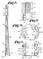
- FIG. 1is an exploded front elevational view of a tool assembly according to the present invention showing a driver tool, a multi-purpose installation tool implant engaging member stabilizer sleeve/tang container and deployer/rod pusher and reducer and an end guide tool shown with an attached polyaxial bone screw.
- FIG. 2is an enlarged front elevational view of an intermediate guide tool of the invention.
- FIG. 3is an enlarged side elevational view of the intermediate guide tool of FIG. 2 .
- FIG. 4is an enlarged rear elevational view of the intermediate guide tool of FIG. 2 .
- FIG. 5is an enlarged front elevational view of the end guide tool of FIG. 1 .
- FIG. 6is an enlarged side elevational view of the end guide tool of FIG. 5 .
- FIG. 7is an enlarged rear elevational view of the end guide tool of FIG. 5 .
- FIG. 8is a cross-sectional view of the end guide tool, taken along the line 8 - 8 of FIG. 5 .
- FIG. 9is an enlarged cross-sectional view of the intermediate guide tool, taken along the line 9 - 9 of FIG. 2 .
- FIG. 10is an enlarged cross-sectional view of the intermediate guide tool, taken along the line 10 - 10 of FIG. 2 .
- FIG. 11is an enlarged bottom plan view of the intermediate guide tool of FIG. 2 .
- FIG. 12is an enlarged and fragmentary perspective view of a polyaxial bone screw of the invention.
- FIG. 13is an enlarged and fragmentary front elevational view of the polyaxial bone screw of FIG. 12 .
- FIG. 14is an enlarged and fragmentary side elevational view of the polyaxial bone screw of FIG. 12 .
- FIG. 15is an enlarged and fragmentary side elevational view of the polyaxial bone screw of FIG. 12 disposed opposite the side shown in FIG. 14 .
- FIG. 16is an enlarged top plan view of the polyaxial bone screw of FIG. 12 .
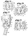
- FIG. 17is an enlarged and fragmentary front elevational view of the polyaxial bone screw of FIG. 12 and the intermediate guide tool of FIG. 2 , shown at an early stage of a twist-on installation of the intermediate guide tool to the bone screw head.
- FIG. 18is an enlarged and fragmentary cross-sectional view of the intermediate guide tool and polyaxial bone screw installation, taken along the line 18 - 18 of FIG. 17 .
- FIG. 19is an enlarged and fragmentary cross-sectional view similar to FIG. 18 , showing a later stage of the twist-on installation of the intermediate guide tool to the bone screw head.
- FIG. 20is an enlarged and fragmentary cross-sectional view similar to FIGS. 18 and 19 , showing the intermediate guide tool installed on the bone screw head.
- FIG. 21is an enlarged, fragmentary and cross-sectional view, taken along the line 21 - 21 of FIG. 20 , showing the intermediate guide tool installed on the bone screw head.
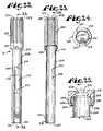
- FIG. 22is an enlarged front elevational view of the multi-purpose tool shown in FIG. 1 .
- FIG. 23is a cross-sectional view of the multi-purpose tool taken along the line 23 - 23 of FIG. 22 .
- FIG. 24is an enlarged bottom plan view of the multi-purpose tool of FIG. 22 .
- FIG. 25is an enlarged and fragmentary cross-sectional view of a portion of the multi-purpose tool shown in FIG. 23 .
- FIG. 26is an enlarged and fragmentary side elevational view of the driver shown in FIG. 1 having a handle, a nut fastener and a stem, with the nut fastener being shown in a first, unengaged position.
- FIG. 27is an enlarged and fragmentary front elevational view of the driver tool similar to FIG. 26 , showing the nut fastener in a second or intermediate position.
- FIG. 28is an enlarged and fragmentary side elevational view similar to FIG. 27 and further showing a cross-sectional view of the nut fastener, taken along the line 28 - 28 of FIG. 27 .
- FIG. 29is an enlarged cross-sectional view similar to FIG. 23 , showing an early stage of the installation of the multi-purpose tool to the end guide tool (shown in side elevation as in FIG. 6 ).
- FIG. 30is an enlarged cross-sectional view similar to FIG. 29 , showing the multi-purpose tool installed to the end guide tool (shown in side elevation).
- FIG. 31is an enlarged cross-sectional view of the multi-purpose tool, taken along the line 31 - 31 of FIG. 30 , showing the end guide tool in front elevation.
- FIG. 32is an enlarged and fragmentary cross-sectional view of the multi-purpose tool similar to FIG. 31 , shown attached to the end guide tool and also showing a sliding engagement stage of attachment to the driver (shown in front elevation).
- FIG. 33is an enlarged and fragmentary front elevational view similar to FIG. 32 , showing the driver nut fastener in the intermediate position shown in FIG. 27 .
- FIG. 34is an enlarged and fragmentary front elevational view similar to FIG. 33 , showing the driver in fixed engagement with the guide tool.
- FIG. 35is an enlarged and fragmentary view similar to FIG. 34 , showing the driver in fixed engagement with the guide tool and with the driver nut fastener shown in cross-section as in FIG. 28 , and the multi-purpose tool shown in cross-section as in FIG. 32 .
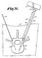
- FIG. 36is a partial and generally schematic cross-sectional view of a patient's spine, showing a thin guide pin installed at a first side thereof and a bone screw tap tool and threaded bore made thereby at a second side thereof.
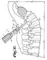
- FIG. 37is a partial and generally schematic view of a patient's spine showing a tool assembly according to the invention with attached bone screw being guided toward the threaded bore in a vertebra in an early stage of a process according to the invention.
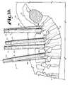
- FIG. 38is a partial and generally schematic view of a patient's spine, showing an end guide tool and the multi-purpose tool of the present invention being positioned for use in a process according to the invention.
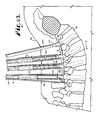
- FIG. 39is a partial and generally schematic view of a patient's spine, showing a pair of end tools and a pair of intermediate tools of the present invention being positioned for use in a process according to the invention.
- FIG. 40is a partial and generally schematic view of a patient's spine, showing a pair of end tools with the flexible tangs containing a rod which has now been inserted and a pair of intermediate tools of the present invention with one of the intermediate tools shown with an attached multi-purpose tool in a rod reduction application and one of the end guide tools shown partially cut-away, illustrating a closure top installation tool disposed within the end tool and cooperating with a bone screw closure member, the tools being utilized in an early stage of rod implantation to guide the rod toward the bone screws.
- FIG. 41is a partial and generally schematic cross-sectional view of the spine, taken along the line 41 - 41 of FIG. 40 , showing an early stage of implanting a rod according to a process of the invention.
- FIG. 42is a partial and generally schematic view of a patient's spine similar to FIG. 40 , showing cut-away portions of all four tool assemblies, illustrating an intermediate stage of implanting a rod.
- FIG. 43is a partial and generally schematic view of a patient's spine similar to FIG. 42 , showing cut-away portions of three of the tool assemblies and one assembly without an end tool, illustrating the rod fully installed in all the bone screws.
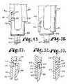
- FIG. 44is an exploded front elevational view of an anti-torque tool assembly according to the present invention showing an antitorque tool and a closure top installation tool cooperating with a break-away bone screw closure member.
- FIG. 45is a bottom plan view of the anti-torque tool shown in FIG. 44 .
- FIG. 46is a fragmentary and front elevational view of a bone screw with attached break-away closure member and installed rod, and further showing the closure top installation tool of FIG. 44 with the anti-torque tool.
- FIG. 47is a fragmentary and front elevational view of a bone screw and anti-torque tool with portions broken away to show a torque driver advancing toward the break-away closure member in a process according to the invention.
- FIG. 48is a fragmentary and front elevational view of the bone screw and anti-torque tool similar to FIG. 47 , with portions broken away to show a fully installed rod and closure member with the break-away head removed from the top by the torque driver.
- FIG. 49is an enlarged and fragmentary front elevational view showing an alternative snap- or twist-on and twist-off attachment structure according to the invention on a guide tool and on a cooperating polyaxial bone screw head.
- FIG. 50is an enlarged and fragmentary front elevational view of the attachment structure shown in FIG. 49 showing the guide tool installed on the bone screw head.
- FIG. 51is an enlarged and fragmentary view of the attachment structure shown in FIG. 49 with portions removed to show the detail thereof showing an early stage of the snap on installation of the guide tool on the bone screw head.
- FIG. 52is an enlarged and fragmentary view similar to FIG. 51 showing a later stage of installation of the guide tool on the bone screw head.
- FIG. 53is an enlarged and fragmentary view similar to FIGS. 51 and 52 showing the guide tool installed on the bone screw head.
- FIG. 54is an enlarged and fragmentary front elevational view of a polyaxial bone screw shank with a pivotally attached head or receiver and shown with a guide tool, with portions broken away to show the detail thereof, illustrating a second alternative snap-on and pry-off attachment structure according to the invention on a guide tool and on the polyaxial bone screw head, showing and early stage of snap-on installation.
- FIG. 55is an enlarged and fragmentary view, identical to FIG. 54 with the exception that an intermediate stage of snap-on installation is shown.
- FIG. 56is an enlarged and fragmentary view, identical to FIG. 54 with the exception that the guide tool is shown fully installed on the bone screw head.
- FIG. 57is an exploded perspective view of a bone screw having a shank and a head or receiver, the receiver having a third alternative snap-on or slide-on and slide-off or push-off attachment structure according to the invention.
- FIG. 58is an enlarged front elevational view of the receiver of FIG. 57 .
- FIG. 59is an enlarged side elevational view of the receiver and shank of FIG. 57 shown with a guide tool with cooperating attachment structure.
- reference numeral 1generally designates a tool assembly according to the present invention
- reference numeral 2generally designates a tool set according to the invention, made up of a number and variety of tool assemblies 1 for use in installing a set of bone screws 4 into a patient's spine 6 , followed by the installation of an orthopedic spinal rod or longitudinal member 8 into the bone screws 4 in a process according to the present invention.
- the tool embodiment assembly 1includes an end guide tool 9 or an intermediate guide tool 10 mated with a multi-purpose installation tool 12 configured to function as a guide tool stabilizer and supporter, a tang container and deployer and a rod pusher and reducer.
- the tool assembly 1may further include a driver 14 .
- a set 2 of the illustrated embodimentincludes a pair of end guide tools 9 and a plurality of intermediate guide tools 10 , which in the illustrated embodiment includes a pair of intermediate guide tools 10 on each side of a patient's spine 6 , but which can include none, one or many intermediate guide tools 10 depending upon the particular application, so that one intermediate guide tool 10 is used for each intermediate bone screw 4 to which the rod 8 is to be attached.
- the driver 14is used in conjunction with the guide tool 9 and the guide tool 10 to implant bone screws 4 in the patient's spine 6 and, in particular, in vertebrae 16 along the spine 6 as shown in FIG. 37 .
- Each end guide tool 9 and intermediate guide tool 10is configured to cooperate with the multi-purpose installation tool 12 to install the rod 8 .
- Rods 8 or other longitudinal membersare often installed on both sides of the spine 6 during the same procedure.
- any reference to the words top, bottom, up and down, and the like, in this applicationrefers to the alignment shown in the various drawing figures, as well as the normal connotations applied to such devices, and is not intended to restrict positioning of the assembly 1 or the tool set 2 in actual use.
- each end guide tool 9has an elongate body 18 that is sized and shaped to be sufficiently long to extend from implanted bone screws 4 through an exterior of a patient's skin 20 so as to provide an outwardly extending and upper handle portion 22 that allows and provides for gripping by a surgeon during procedures utilizing the tool set 2 , with or without an attached multi-purpose installation tool 12 and/or driver 14 .
- Each of the end guide tools 9further includes an intermediate portion 24 and a lower implant engaging portion 26 which includes opposed implant engaging members for securing one the implants there between.
- Each end guide tool 9has a substantially flat back wall 28 joining a pair of substantially cylindrically shaped side walls 32 and 33 .
- the back wall 28provides a flexible holding structure that includes a pair of parallel slits 34 extending from near the lower handle portion 22 to an end 36 of the tool 9 .
- a flap or flexible tang 38 disposed between the slits 34 in the back wall portionis configured to flex or spring radially outwardly from the bottom and about the top thereof in a deployed position, as is shown in FIG. 6 .
- the back wall portion flap or tang 38provides a surgeon with some additional working space and flexibility when working with the rod 8 during surgery, so the rod 8 can extend beyond the bone screws 4 while remaining under resilient tension produced by outward biasing of the flexible back wall portion so that the rod 8 remains in a desired position and under control. Further, the tang or flap 38 also functions to urge the rod 8 toward the other tools in the tool set 2 , as shown in FIG. 40 and as will be discussed more fully below.
- each end guide tool 9includes a laterally or sideways opening channel 39 , forming a U-shaped cross-section, a C-shaped cross-section, a crescent shaped cross-section or the like having a generally elongate and axially extending opening 40 with a side-to-side width 42 .
- the channel 39mates with other channel structure described below so as to extend the entire length of the end guide tool 9 .
- the opening 40communicates with and forms part of the channel 39 that opens at an upper end 43 of the guide tool 9 and also opens perpendicularly with respect to a central axis of the guide tool 9 or laterally to one side of the end guide tool 9 , thus defining the opening 40 .
- the opening 40narrows near the upper end 43 providing a slot 44 having a side-to-side width 45 that is smaller than the side-to-side width 42 .
- the slot 44is configured for sliding engagement with a rotational locking pin 46 disposed on the driver 14 and discussed more fully below.
- Disposed on either side of the slot 44are co-planar surfaces 47 and 48 that are parallel with the back wall 28 .
- the surfaces 47 and 48 , as well as the back wall 28provide alignment surfaces when the multi-purpose tool 12 is inserted onto the guide tool 9 discussed more fully below.
- the opening 40is of substantially constant width through a mid-section 48 of the handle portion 22 , sufficiently wide to receive additional tools and/or a closure top for sideways loading into the channel 39 , as will be discussed below.
- the upper portion 22also includes an outer helically wound discontinuous guide and advancement structure 50 disposed on outer surfaces of both of the substantially cylindrically shaped side walls 32 and 33 , which may include conventional helically wound V type threads, buttress threads, helically wound square threads, or other guide and advancement structure to cooperate with equivalent or mateable structure within the multi-purpose installation tool 12 and the driver 14 , as described more fully below.
- the advancement structure 50extends from near the intermediate portion 24 to the open end 43 .
- the back wall 28 extending between the threaded sides 32 and 33has an outer substantially planar and smooth surface finish.
- each end guide tool 9Extending from the upper portion 22 and into the intermediate portion 24 of each end guide tool 9 is an outward facing channel 51 that has an opening 52 with a side-to-side width 53 that is somewhat smaller than the width 42 of the upper handle portion 22 , such that the channel 51 and opening 52 are sized and shaped to receive and allow passage of certain tools and implants, as described below.
- a remaining portion of the end guide tool intermediate portion 24 and the lower portion 26includes a groove or channel 55 , with an elongate, axially extending and radially outward opening 57 , having a side-to-side width 58 that is slightly smaller than the width 42 of the opening 40 , but larger than the slot width 45 and the opening width 53 .
- the channel opening 57is disposed opposite the flexible tang or flap 38 . All of the channels 39 , 51 and 55 communicate with one another and are aligned with one another so as to provide a continuous elongate interior and sideways open passageway with an open side from near the top end 43 to near the bottom 36 thereof.
- each end guide tool channel opening 57is sized and shaped to slidingly receive a respective end 59 of the rod 8 therein. It is foreseen that one or all of the channel openings forming the open side that extends from near the top end 43 to near the bottom 36 of the guide tool 9 may be sized and shaped to receive the end 59 of the rod 8 .
- the rod 8may be of uniform or non-uniform diameter, regular or uneven surface construction, or smooth or roughened surface finish, and that the channel openings may in turn be sized and shaped to receive such a rod end that may exhibit a greater or smaller width or diameter than at other locations along the rod.
- the slits 34are spaced in order to have a back wall or flap flex region having a size and shape to allow at least partial passage of a respective end 59 of the rod 8 between the side walls 32 and 33 .
- a rod abutment recess 61located near the end guide bottom 36 is a rod abutment recess 61 that is sized and shaped for the purpose of bridging the rod 8 when the end guide tool 9 is rotated for removal, as described below. However, it is foreseen that other removal means could be used.
- the end guide tool 9also receives a closure top 62 , as will be described below.
- a helical wound, discontinuous guide and advancement structure 64which may include conventional helically wound V-shaped threads, buttress threads, reverse angle threads, helically wound square threads, or other guide and advancement structure to cooperate with equivalent or mateable structure within the bone screw heads 4 and on the closure top 62 , as also described below.
- the substantially cylindrical side walls 32 and 33include an outer radially extending bevel 66 and substantially cylindrical outer side walls 68 and 69 , respectively.
- the walls 68 and 69uniformly increase the thickness of the respective side walls 32 and 33 , resulting in a substantially cylindrical cross-section of greater diameter than a diameter created by an outer surface of the side walls 32 and 33 at the intermediate portion 24 .
- the walls 68 and 69are configured with co-planar front walls or facets 70 and co-planar back walls or facets 71 with the facets 70 being disposed parallel to the facets 71 , providing for alignment and mating with an interior of the multi-purpose installation tool 12 to ensure that the end guide tool 9 is retained in a selected, non-rotatable position with respect to the multi-purpose installation tool 12 when installed therein.
- Each of the walls 68 and 69can include an abutment pin 67 located at an outer surface thereof and near the bottom or end 36 . The pin 67 may serve as a stop for the multi-purpose installation tool 12 as will be described more fully below; however, such a pin stop is not always needed.
- each end guide tool 9disposed on an inner surface of each of the side walls 32 and 33 , is a radially inward facing attachment structure, generally 72 , that will be described below in conjunction with a similar structure on the intermediate guide tool 10 and the bone screw 4 .
- Each of the intermediate guide tools 10have a somewhat similar overall shape when compared to the end guide tools 9 in that both are preferably of the same axial length and width and also have much structure in common; however with certain differences as noted.
- Each intermediate guide tool 10has an overall elongate body 74 with an upper handle portion 76 , an intermediate portion 77 and a lower implant engaging portion 78 which includes opposed implant engaging members for securing one of the implants there between.
- the body 74is generally C-shaped defining a radially outward opening 79 communicating with an elongate and axially extending channel 80 defined by a rear wall 81 having a lower web edge 96 and side walls 82 and 83 .
- the channel 80 front opening 79extends parallel to an axis B of the body 74 and has a side-to-side width 85 configured to receive tools and elements described below.
- the opening 85narrows near an upper end 87 providing an elongate slot 88 having a side-to-side width 89 that is smaller than the width 85 .
- the slot 88is configured for sliding engagement with the pin 46 disposed on the driver 14 and discussed more fully below.
- Disposed on either side of the slot 88are co-planar surfaces 91 and 92 that are parallel with the rear wall 81 .
- the surfaces 91 and 92 , as well as the rear wall 81provide alignment surfaces when the multi-purpose tool 12 is inserted onto the guide tool 10 , discussed more fully below.
- the side-to-side opening width 85is substantially constant through a mid-section 90 of the handle portion 76 , sufficient to receive additional tools and/or a closure top, as will be discussed below.
- the upper or handle portion 76also includes an outer helically wound discontinuous guide and advancement structure 93 disposed on outer sides of both of the substantially cylindrically shaped side walls 82 and 83 , which may include conventional helically wound V-threads, helically wound square threads, buttress threads or other guide and advancement structure to cooperate with equivalent or mateable structure within the multi-purpose installation tool 12 and the driver 14 as described more fully below.
- the advancement structure 93extends from near the intermediate portion 77 to the open end 87 .
- An outer surface of the rear wall 81 extending between the threaded sides 32 and 33is substantially planar and smooth.
- the upper or handle portion 76further includes an outward facing channel 94 communicating with the channel 80 .
- the channel 94is defined in part by a rear wall or web 95 having a lower end with the web edge 96 , the wall 95 being integral with the wall 81 .
- Communicating with the channel 94is an elongate and axially extending opening 98 having a side-to-side width 99 that is somewhat smaller than the width 85 of the opening 79 .
- the opening 98is further defined by the walls 82 and 83 .
- the channel 94 and opening 98are configured to receive, contain and allow translational movement therealong or rotational relative movement of certain tools, as described more fully below.
- channel 94may extend into the intermediate portion 77 to provide greater strength and stability to the lower portion 78 of the intermediate tool 10 , with the opening 98 also extending into the lower portion 78 providing greater retention of small tools or parts being inserted through the channel 94 .
- the intermediate portion 77 of the intermediate tool 10includes two spaced side walls or legs 102 and 103 , extending from and integral with the side walls 82 and 83 , respectively.
- the legs 102 and 103have outer surfaces that are partially cylindrical.
- each of the legs 102 and 103include an outwardly facing radially extending bevel 106 integral with substantially cylindrical outer side walls 107 and 108 , respectively.
- the outer walls 107 and 108extend along the length of the lower portion 78 and uniformly increase the thickness of the respective legs 102 and 103 , resulting in a substantially cylindrical cross-section of greater outer diameter at the lower portion 78 than an outer diameter created by the outer surfaces of the legs 102 and 103 along the intermediate portion 77 .
- the walls 107 and 108are configured with co-planar front facets or walls with flat surfaces 109 and co-planar rear facets or walls with flat surfaces 110 , the facets 109 disposed parallel to the facets 110 , providing for alignment with an interior of the multi-purpose installation tool 12 to ensure that the intermediate guide tool 10 is properly mated with and retained in a selected, non-rotatable position with respect to the multi-purpose installation tool 12 when installed therein.
- the legs 102 and 103define an elongate and axially extending passthrough slot 111 sized and shaped to slidingly receive the rod 8 .
- the slot or openingextends from the lower edge of the web end 96 of the rear wall 95 to an open end or bottom 112 of the tool 10 configured to secure an open ended spinal surgery implant there between.
- each implant engaging leg member 102 and 103 of the intermediate guide tool 10Near the bottom 112 of each implant engaging leg member 102 and 103 of the intermediate guide tool 10 is a helically wound but discontinuous square thread 114 and it is foreseen that other type of guide and advancement structure may be utilized such as helically wound flange forms, reverse angle threads, buttress threads, etc.
- the thread form 114cooperates with the closure top 62 , as described below.
- the lower end of each leg 102 and 103 of the intermediate guide tool 10also includes a cutout or rod-abutment recess 116 similar to the recess 61 described with respect to the end tool 9 .
- Each of the walls 107 and 108can include an abutment pin 118 located at an outer surface thereof and near the bottom or end 112 .
- the pin 118may serve as a stop for the multi-purpose installation tool 12 as will be described more fully below.
- each leg 102 and 103 of the intermediate guide tool 10disposed on inner substantially cylindrical surfaces 120 and 121 , respectively, is a radially inward facing attachment structure, generally 124 , substantially similar to the structure 72 disposed on the end guide tool 9 .
- the structure 124will be described herein in conjunction with the bone screw 4 .
- the embodiment shownincludes an attachment structure 124 having a first projection, stop or pin 126 in spaced relation with a second smaller projection, stop or pin 127 , both pins being disposed on the surface 120 .
- the structure 123further includes a cooperating third projection, stop or pin 130 in spaced relation with a fourth smaller projection, stop or pin 131 , the pins 130 and 131 being disposed on the surface 121 .
- the larger pins 126 and 130are substantially configured the same, both being substantially rounded, radially inward projecting nodules, each having a ridge or lip 132 and 133 , respectively, projecting upwardly toward the guide and advancement structure 114 and that preferably follows the curvature of the respective leg inner surface 120 and 121 .
- the lips 132 and 133 with respective surfaces 120 and 121define slots 134 and 135 , respectively, for receiving the bone screw 4 as will be discussed more fully below.
- the pin 126is configured slightly larger than the pin 130 , requiring similar modification in the bone screw 4 , resulting in a method of operation wherein the bone screw 4 may only be mated with the guide 9 or 10 from a single direction, ensuring appropriate alignment between the bone screw 4 and guide tool advancement structure 114 with respect to the installment of the closure top 62 .
- Each of the larger pins 126 and 130is also disposed at substantially the same distance from respective bottom surfaces 138 and 139 , at the end 112 of the guide tool 10 and adjacent a rod-abutment recess 116 . Furthermore, each of the larger pins 126 and 130 is also disposed at substantially the same distance from respective parallel seating surfaces 140 and 141 , that form a base of the guide and advancement structure 114 . Additionally, in this embodiment the pins 126 and 130 are disposed in diametrically opposed relation when viewed in cross-section as shown in FIG. 10 .
- the smaller pins 127 and 131are also substantially configured the same, the pin 131 being slightly larger than the pin 127 , but otherwise both pins 127 and 131 being substantially rounded, radially inwardly projecting nubs, each disposed at substantially the same distance from the respective bottom surfaces 138 and 139 and the respective seating surfaces 140 and 141 . Furthermore, the pins 127 and 131 are disposed in diametrically opposed relation when viewed in cross-section as shown in FIG. 10 . Each of the pins 127 and 131 are disposed closer to the respective end surfaces 138 and 139 than are the larger pins 126 and 130 .
- pinsare of different sizes to provide for mating of the guide tool 9 or 10 with the bone screw 4 from a single direction, resulting in a desired alignment between the bone screw 4 guide and advancement structure 114 and the closure top 62 guide and advancement structure.
- each of the bone screws 4further includes a threaded shank 148 attached to the head 146 , the shank 148 for screwing into and seating in a vertebra 16 that is part of the human spine 6 .
- the head 146includes first and second arms 150 and 151 that define a rod receiving channel 153 passing therethrough.
- Each of the bone screw shanks 148includes an upper portion 154 that extends into the head 146 and is operationally secured therein, so that the head 146 is rotatable on the shank 148 until locked in position through engagement with the rod 8 under pressure.
- the receiver portion 145is disposed on outer surfaces of the arms 150 and 151 .
- the receiver portion 145 of arm 150includes a slot or groove 158 communicating with a recess 159 defined in part by a flange 160 .
- the groove 158 and recess 159open at a front surface 162 of the arm 150 and extend across a facet 163 and into a side surface 164 thereof.
- the groove 158is configured to mate with the large pin 126 with the lip 132 extending into the recess 159 and the flange 160 disposed in the slot 134 when the guide tool 10 is attached to the bone screw head 146 .
- the width of the slot 134is sized to prevent passage therethrough of the pin 126 except by twisting or rotational relative movement therebetween.
- the receiver portion 145 of the arm 150further includes a rounded aperture 165 disposed substantially centrally on a face or facet 167 of the arm 150 , the facet 167 disposed adjacent to the side surface 163 .
- the aperture 165is configured to mate with the small pin 127 .
- the receiver portion 145 of the arm 151defines a groove 168 communicating with a recess 169 defined in part by a flange 170 .
- the groove 168 and recess 169open at a back surface 172 of the arm 151 and extend across a facet 173 into a side surface 174 thereof.
- the groove 168is configured to mate with the large pin 130 with the lip 133 extending into the recess 169 and the flange 170 disposed in the slot 135 when the guide tool 10 is attached to the bone screw head 146 .
- the receiver portion 145 of the arm 151further includes a rounded aperture 175 disposed substantially centrally on a face or facet 177 of the arm 151 , the facet 177 disposed adjacent to the side surface 173 .
- the aperture 175is configured to mate with the small pin 131 .
- the guide tool 10is rotated about its axis B such that the legs 102 and 103 are lowered into place as shown in FIGS. 17 and 18 , with the facets 167 and 177 of the head 146 disposed between the guide tool legs 102 and 103 , with the facet 167 adjacent the leg 102 and the facet 177 adjacent the leg 103 , thereby aligning the groove 158 with the large pin 126 and the groove 168 with the large pin 130 .
- the head 146may then be twisted into place as shown by the arrow T in FIGS. 18 , 19 and 20 .
- the legs 102 and 103may splay slightly as the head is twisted into place, but come to rest in a generally non-splayed configuration and held in place by the structure of the attachment mechanism to resist splaying.
- the guide tool 9 , 10In order to disengage the guide tool 9 or the guide tool 10 from the bone screw 4 , the guide tool 9 , 10 is rotated counterclockwise from an attaching configuration (opposite to the arrow T), when viewing from the top so as to disengage the lips 132 and 133 from the recesses 159 and 169 , respectively. In this manner, end guide tools 9 and intermediate guide tools 10 that have previously twisted on, now twist off of respective bone screws 4 .
- a preferred embodiment of the inventionhas the respective pins of the attachment structure on the guide tools and the grooves on the bone screw heads, it is foreseen that these elements could be reversed in total or part in accordance with the invention.
- other suitable attachment structurecould be used, such as sloped or tapered undercut surfaces on the screw heads that overlap, mate and interlock with radially or linearly projecting structure on or near the ends of the guide tools. Such projecting structure can be snapped on or clipped on and translated up to provide for anti-splay overlapping surfaces.
- a groovecould be put in the outer surface of the screw head and a fin on the guide tool could snap or slide into the groove.
- the recesses 61 and 116 disposed on the respective guide tools 9 and 10are sized, shaped and positioned so that when the rod 8 is located in the bone screws 4 , the guide tools 9 and 10 can rotate about respective axes A and B, with the recess 61 and 116 allowing the respective guide tool 9 and 10 to straddle over the rod 8 , thereby allowing the guide tool 9 and 10 to twist relative to the bone screw 4 and free the attachment structures 72 and 124 from the receiver portion 145 of the bone screw 4 and thereafter be removed after all procedures are complete, as described below.
- the closure top 62closes between the spaced bone screw arms 150 and 151 to secure the rod 8 in the channel 153 .
- the closure top 62can be any of many different plug type closures. With reference to FIGS. 46-48 , preferably the closure top 62 has a cylindrical body 180 that has a helically wound mating guide and advancement structure 181 .
- the guide and advancement structure 181can be of any type, including V-type threads, buttress threads, reverse angle threads, or square threads.
- the guide and advancement structure 181is a helically wound flange form that interlocks with a reciprocal flange form as part of a guide and advancement structure 183 on the interior of the bone screw arms 150 and 151 .
- a suitable locking guide and advancement structure of this typeis disclosed in U.S. Pat. No. 6,726,689 from Ser. No. 10/236,123 which is incorporated herein by reference.
- the helically wound guide and advancement structures 64 and 114 in the respective guide tools 9 and 10are sized and shaped to receive the mating guide and advancement structure 181 of the closure top 62 and align with the guide and advancement structure 183 of the bone screw 4 to form a generally continuous helically wound pathway, but does not require locking between the closure top 62 and the tools 9 and 10 , even when an interlocking flange form is utilized on the closure top 62 .
- the guides 64 and 114allow the closure top 62 to be rotated and the surgeon to develop mechanical advantage to urge or drive the rod 8 , while still outside or partially outside the bone screw 4 , toward and into the bone screw head 146 . This is especially helpful where the rod 8 is bent relative to the location of the vertebra 16 (which is sometimes the case) to which the rod 8 is to attach and is not easily placed in the bone screw head 146 without force and the mechanical advantage provided by the guides 64 and 114 .
- the guide and advancement structures 64 and 114 on the respective tools 9 and 10are located and positioned to align with the guide and advancement structure 183 on the insides of the bone screw arms 150 and 151 , as shown in FIG. 42 and pass the closure top 62 therebetween while allowing the closure top 62 to continue to rotate and to continuously apply force to the rod 8 , so as to aid in seating the rod 8 in the bone screw head 146 .
- Each closure top 62also preferably includes a break-off head 186 that breaks from the cylindrical body 180 in a break-off region 187 upon the application of a preselected torque, such as 95 to 120 inch-pounds.
- the break-off head 186preferably has a hexagonal cross section faceted exterior that is configured to mate with a similarly shaped socket of a final closure driving or torquing tool 190 described below. It is foreseen that different driving heads or other methods of driving the closure top 62 can be utilized with certain embodiments of the invention, such as non-break-off closure top designs.
- the present inventionis not intended to be restricted to a particular type of bone screw, bone screw closure mechanism, or bone screw and guide tool attachment mechanism.
- a polyaxial type bone screw 4is utilized wherein the shank 148 is locked in position by direct contact with the rod 8 .
- the tool set 2 of the present inventioncan be used with virtually any type of bone screw, including fixed monoaxial and polyaxial bone screws of many different types wherein the head is locked relative to the shank by structure other than in the manner described in the illustrated embodiment. It is also foreseen that the screws could be cannulated.
- the multi-purpose installation tool 12 of the tool assembly 1 of the inventionincludes an upper translation nut 202 rotatably and free wheelingably attached to a lower guide tool stabilizer or support sleeve 204 .
- the sleeve 204has an inner substantially cylindrical surface 205 defining a substantially hollow passageway 206 sized and shaped to slidingly receive an end tool 9 or an intermediate tool 10 therein. Alternatively, is foreseen that the sleeve could have an inner and outer planar surface.
- the sleeve 204is elongate and includes a receiving end 207 , a substantially cylindrical outer body 208 and a translation nut attachment end portion 210 disposed opposite the receiving end 207 .
- the receiving end 207not only functions to receive the guide tool 9 or 10 into the sleeve 204 , but also as a pressing block 218 for contacting the flexible flap or spring tang 38 and as a pressing end 207 for contacting the rod 8 and translating the rod 8 toward the bone screw head 146 when the multi-purpose installation tool 12 is installed on the guide tool 9 or 10 , as will be discussed more fully below.
- the cylindrical body 208further defines a slotted U-shaped or C-shaped channel 212 that opens radially at an opening 213 and also opens at the receiving end 207 and extends substantially along a length of the body 208 to a location 214 spaced from the nut attachment end portion 210 .
- the channel openinghas a side-to-side width 216 sized to receive the back wall tang portion or flexible flap 38 of the end guide tool 9 therethrough, when aligned therewith.
- the multi-purpose installation tool 12is shown partially removed from an end guide tool 9 and deploying the tang 38 after the bone screw has been inserted.
- the multi-purpose installation tool 12can be removed, turned 180° and reattached to the end guide tool 9 thereby providing access through the channel opening 213 for protrusion of the back wall tang portion or flap 38 of the end guide tool 9 .
- the flap 38is thus not encumbered or restricted by the tool 12 during the rod pushing application and the flap 38 can be flexed outwardly by a rod 8 (not shown)or other forces, when the devices are assembled in this configuration.
- the block 218Disposed flush to the lower sleeve end 207 and rigidly attached to the inner cylindrical surface 205 is the solid guide tool alignment and tang/rod pressing block 218 .
- the block 218has a substantially smooth, planar and rectangular surface 220 facing inwardly radially from the inner surface 205 .
- the block 218also follows the curve of the cylindrical surface 220 at a surface 222 thereof.
- the block 218has a segment shape when observed from a bottom plan view.
- the term segment used hereinis defined as the part of a circular area bounded by a chord and an arc of a circle cut off by the chord. This segment shape of the block 218 provides a mechanical advantage for compressing the flexible flap 38 flush with the end guide tool 9 and for advancing the rod 8 into the bone screw 4 with the multi-purpose installation tool 12 which will be discussed more fully below.
- the flat, rectangular surface 220provides structure for installing the guide tool 9 or 10 in a mating and desired alignment with respect to the multi-purpose installation tool 12 .
- a preferred alignmentis that the rear wall 81 of the tool 10 be disposed adjacent to the surface 220 when inserting the tool 10 into the multi-purpose installation tool 12 .
- the tool 10is slid into the multi-purpose tool sleeve 204 , with the block 218 preventing axial rotation of the tool 10 with respect to the sleeve 204 , and resulting in the preferred alignment of the opening 79 and the pass-through slot 11 of the tool 10 and the U-shaped channel 212 of the multi-purpose tool in this application.
- the block 218 with the planar surface 220provides for the insertion of the tool 9 in a first, installation tang containing position or a second, rod pushing position.
- the flexible back wall portion or tang 38 of the tool 9it is advantageous for the flexible back wall portion or tang 38 of the tool 9 to be fully restrained by the multi-purpose installation tool 12 and for the walls 68 and 69 to be locked in a non-splayable or anti-splay position. Therefore, in the first, bone screw installation tang containing position, the multi-purpose installation tool 12 is inserted onto the tool 9 with the back wall 28 of the tool 9 disposed adjacent to the sleeve surface 220 .
- the tool 9 and the sleeve 204are attached with the block 218 preventing axial rotation of the tool 9 with respect to the multi-purpose installation tool 12 .
- the multi-purpose installation tool 12is removed from the end guide tool 9 and replaced thereon with the slot 44 and channel openings 40 and 94 adjacent to and facing the alignment block 218 .
- the translation nut 202 of the multi-purpose installation tool 12is substantially cylindrical in shape and is shown with outer grooves 223 to aid a surgeon in handling the multi-purpose installation tool 12 and rotating the nut 202 .
- the nut 202further includes an inner cylindrical surface 224 defining an inner substantially cylindrical passage 226 communicating with the passage 206 of the sleeve 204 .
- the inner surface 224further includes a helical guide and advancement structure as shown by a V-shaped thread 228 that is configured to mate with the guide and advancement structure 50 of the end guide tool 9 or the guide and advancement structure 93 of the intermediate guide tool 10 .
- the inner cylindrical surface 224extends from an upper open end 230 of the translation nut 202 to an annular seating surface 232 extending radially outwardly and perpendicular to the cylindrical surface 224 .
- the surface 224 with associated thread 228is of a length that provides an equivalent translation distance of the multi-purpose installation tool 12 , and in particular the tang/rod pressing block 218 , with respect to the guide tool 9 or 10 such that the pressing block 218 can be used to gradually push the rod 8 toward the bone screw 4 for the entire translation distance by rotating the nut 202 which can be continued until the rod is fully seated in the head of the bone screw.
- the sleeve 204is in sliding contact with the nut 202 .
- a lower portion 234 of the nut 202further defines a second inner cylindrical surface 236 of greater diameter than the surface 224 .
- the surface 236has a diameter slightly greater than a diameter of the sleeve 204 and is configured to slidingly receive the sleeve 204 into the nut 202 along the surface 236 .
- the nut 202further defines an annular recess or groove 238 configured to receive a pin 240 rigidly fixed to the sleeve 204 .
- the pin 240may be accessed for attachment and removal from the sleeve 204 through an aperture 242 disposed in the translation nut 202 .
- the pin 240slidingly mates with the nut 202 within the recess 238 , keeping the nut 202 and sleeve 204 in an attached but freely rotatable relation.
- the driver 14 of an assembly 1includes a handle 250 , a guide tool fastener or nut 252 , and an elongate cylindrical stem or shaft 254 having a lower cylindrical portion 255 integral with a bone screw engager shown as a socket 256 .
- the socket 256is configured to mate with the upper part of the bone screw shank 154 .
- the shaft 254 with attached socket 256is receivable in and passes through the interior of the guides 9 and 10 , such as the channel 80 of the guide tool 10 .
- the lower portion 255has a slightly smaller diameter than a diameter of the remainder of the shaft 254 , this smaller diameter provides for adequate clearance of the portion 254 from the guide and advancement structures 64 and 114 when the shaft 254 is installed within the interior of the respective guide tools 9 and 10 .
- the stem or shaft 254is rigidly attached to the handle 250 and coaxial therewith. Both the handle 250 and the guide tool fastener 252 include outer grooves 258 and 259 respectively, about outer cylindrical surfaces thereof to aid in gripping and rotating the respective components.
- the guide tool fastener 252is a substantially hollow cylinder disposed in coaxial relationship with the handle 250 and the shaft 254 .
- the fastenerhas a threaded inner cylindrical surface 262 disposed at a lower portion 263 thereof, the threaded surface 262 configured to mate with the guide and advancement structure 50 of the end guide tool 9 or the guide and advancement structure 93 of the intermediate guide tool 10 .
- the fastener 252is disposed on the driver 14 between an annular surface 264 of the handle 250 and the pin 46 that is fixed to the shaft 254 and extends laterally therefrom.
- the driver 12further includes a lateral pin 266 projecting radially outwardly from a cylindrical surface 268 adjacent the handle 250 .
- the cylindrical surface 268is integral with the handle 250 and fixedly attached to the shaft 254 .
- the pin 266is disposed within an annular recess 270 defined by the cylindrical surface 268 , and surfaces of the fastener 252 , including an upper seating surface 272 , a lower seating surface 274 and an inner cylindrical surface 276 .
- the pin 266 disposed in the recess 270allows for both rotational and axial or vertical translational movements of the fastener 252 with respect to the shaft 254 .
- the fastener 252is rotatable about an axis C.
- the fasteneris slidable along the axis C between the annular surface 264 and the pin 46 , with FIG. 26 showing a first or unattached position with the fastener 252 in contact with the annular surface 264 and FIGS. 27 and 28 showing a second, engagement position, with the fastener 252 partially covering, but not contacting the pin 46 , with the pin 266 abutting the upper seating surface 272 prohibiting further downward or vertical (axial) translational movement of the fastener 252 with respect to the shaft 254 .
- the pin 46is configured for sliding engagement with both the slot 44 of the guide tool 9 and the slot 88 of the guide tool 10 when the driver shaft 254 is disposed in an interior of the guide tool 9 or 10 .
- the pin 46is received in the slot 44 or the slot 88 , any relative rotational movement between the guide tool 9 or 10 and the driver 14 is prevented, but the driver is free to slide axially with respect to the guide tool 9 or 10 .
- the fastener or nut 252is slid into the second position shown in FIGS.
- a three-component assembly 1including the guide tool 9 , the multi-purpose installation tool 12 and the driver 14 may be assembled as follows:
- the guide tool 9 shown with attached bone screw 4is inserted into the multi-purpose installation tool 12 with the upper end 43 being inserted into the receiving end 207 of the multi-purpose installation tool 12 .
- illustratedis a particular assembly wherein the multi-purpose installation tool 12 is being utilized as a support or stabilizer for the end guide tool 9 during installation of the bone screw 4 into the vertebra 16 , specifically, to contain and compress the tang 38 and to provide extra support to the walls, such as walls 68 and 69 of tool 9 .
- the guide tool 9is received into the multi-purpose installation tool 12 with the rear wall 28 facing the alignment block 218 as shown in FIG. 29 .
- the translation nut 202is then rotated clock-wise as viewed from the top end 230 and shown by the arrow X, with the thread 50 of the guide tool 9 mating with the thread 228 disposed on the inner surface 224 of the translation nut 202 .
- the translation nut 202is preferably rotated until the upper end 43 of the guide tool 9 is positioned outside of the body of the nut 202 with a few of the threads 50 exposed as shown in FIGS. 30 and 31 .
- the sleeve 204cannot be translated beyond the pin 67 that stops the sleeve near the rod abutment recess 61 disposed near the end of the guide tool 9 .
- the guide tool 9is held in a preferred bone screw installation position and any rotational movement of the tool 9 is prevented by the alignment block 218 in contact with the co-planar back walls or facets 71 of the guide tool 9 as well as the planar back surface of the tang 38 .
- the flexible back wall portion or flap 38is compressed and retained in place between the side walls 32 and 33 by the alignment block 218 .
- the multi-purpose installation tool 12When the multi-purpose installation tool 12 is used as a rod pusher with the guide tool 9 as shown in FIGS. 38 and 41 , the multi-purpose installation tool 12 is preferably used first as an end guide tool stabilizer and tang 38 container, as already described herein, and thus must first be removed by rotating the translation nut 202 counter-clockwise until the multi-purpose installation tool 12 is disengaged from the end tool guide 9 thereby deploying the tang 38 . Thereafter, the multi-purpose installation tool 12 is removed and replaced on the guide tool 9 with the slot 44 and channel openings 40 and 94 adjacent to and facing the alignment block 218 .
- the translation nut 202is then rotated clock-wise as shown by the arrow X ( FIG. 29 ), with the thread 50 of the guide tool 9 mating with the thread 228 disposed on the inner surface 224 of the translation nut 202 . Similar to what is shown in FIGS. 30 and 31 , the translation nut 202 is rotated clockwise as shown by the arrow X, until the upper end 43 of the guide tool 9 is positioned outside of the body of the nut 202 with some of the threads 50 exposed.
- the guide tool 9is held in position and any rotational movement of the tool 9 is prevented by the alignment block 218 in contact with the co-planar front walls or facets 70 of the guide tool 9 .
- the flexible back wall tang portion or flap 38is not obstructed by the sleeve 204 of the multi-purpose installation tool 12 and may spring out or be further pushed out through the opening 213 of the U-shaped channel 212 .
- An assembly 1 according to the inventionmay also include the intermediate guide tool 10 in the place of the guide tool 9 as shown in FIGS. 40-42 .
- the intermediate guide tool 10includes a pass-through slot 111 rather than a flexible back wall tang portion 38 , the alignment between the multi-purpose installation tool 12 and the guide tool 10 may be the same during bone screw installation as for the pushing of the rod 8 . Therefore, the tool guide 10 may be inserted into the multi-purpose installation tool 12 with either the rear wall 81 or the slot 88 adjacent to and facing the alignment block 218 .
- the translation nut 202is then rotated clock-wise as viewed looking toward the top 87 of the tool 10 , with the thread 93 of the guide tool 10 mating with the thread 228 disposed on the inner surface 224 of the translation nut. Similar to what is shown in FIGS. 30 and 31 , the translation nut 202 is rotated until the upper end 87 of the guide tool 10 is positioned outside of the body of the nut 202 with some of the threads 93 exposed.
- the guide tool 10is held in position, with rotational movement of the tool 10 being prevented by the alignment block 218 in contact with the co-planar front walls or facets 109 or the co-planar rear walls or facets 110 of the guide tool 10 .
- the driver 14is inserted into the guide tool 9 /multi-purpose installation tool 12 combination by inserting the socket end 256 into the end 43 of the guide tool 9 and sliding the shaft 254 into the interior of the guide tool 9 until the socket end 256 contacts and surrounds the upper part of the shank 154 of the bone screw 4 as shown in FIG. 35 .
- the pin 46 on the shaft 254 of the driver 14is aligned with and slid into the slot 44 of the guide tool 9 .
- the guide tool fastener 252is placed in the first or unattached position with the fastener 252 in contact with the annular surface 264 as shown in FIG. 32 . Also as shown in FIG. 32 , preferably, the pin 46 is slid to a position disposed substantially within the slot 44 when the socket end 256 engages the shank 154 of the bone screw 4 .
- the guide tool fastener or nut 252is then rotated clockwise as viewed from the handle and illustrated by the arrow Y in FIG. 33 , from the first unattached position toward the second engaged position, mating the thread 50 located near the end 43 of the guide tool 9 with the inner threaded surface 262 of the nut 252 of the driver 14 .
- the translation nut 202may then be rotated counter-clockwise as shown by an arrow Z in FIG. 33 , and hand-tightened until the translation nut 202 abuts against the fastener 252 , as shown in FIG. 34 .
- the assembly 1is then fully assembled and may be used to install the bone screw 4 into the vertebra 16 as will be described more fully below.
- the driver 14may be removed by rotating the fastener 252 in a counter-clockwise direction (arrow Z) and sliding the shaft 254 out of the multi-purpose installation tool 12 through the open end 230 .
- FIGS. 44 and 45Another tool used in implanting a spinal rod 8 is an antitorque tool 300 illustrated in FIGS. 44 and 45 and further shown in FIG. 44 with a closure top installation tool 302 engaging the break-away portion 186 of the closure top 62 .
- the closure top installation tool 302includes an upper handle portion 303 and a lower, closure top engagement portion 304 configured to mate with and rotate the closure top 62 .
- the antitorque tool 300is also preferably used with a closure top torquing tool 305 , shown in FIGS. 47 and 48 .
- the tool 305is used to torque and set the closure top 62 , so it is snug against the rod 8 , and thereafter break away the break-off head 186 in the manner shown in FIG. 48 .
- the torquing tool 305is preferably in the form of a socket as shown in the drawings to allow for adequate tightening of the closure top 62 and also ease in removal of the break-off head 186 as shown in FIG. 48 .
- the antitorque tool 300includes a tubular hollow shaft 306 that is sized and shaped to be slidably received over the installation tool 302 and also the torquing tool 305 .
- the shaft 306has a lower end portion 308 that has a pair of diametrically spaced, curved bridges 310 .
- Each of the bridges 310is sized and shaped to fit over the rod 8 , shown in FIGS. 47 and 48 .
- the antitorque tool 300allows a surgeon to counter torque applied by the torquing tool 305 , when applying torque to and breaking away the break-off head 186 .
- the antitorque tool 300also has an upper handle 316 disposed perpendicular to the shaft 306 and having an opening 318 through which the installation tool 302 and the torquing tool 305 passes in the manner suggested by FIGS. 46-48 .
- the previously described toolsare utilized to attach one or more rods 8 to the human spinal column 6 .
- the procedureis begun by selection of a bone screw 4 in accordance with the size of the patient's vertebra 16 and the requirements of the spinal support needed.
- Bone screws 4 having a rotatable or polyaxial head 146are preferred but not required for the procedure, as such allow relatively easy adjustment of the rod 8 in the tools 9 and 10 during placement and for movement of the tools 9 and 10 , as described below.
- the bone screw 4is also preferably cannulated so as to be receivable over and guided by a guide pin 355 as discussed more fully below.
- a relatively small incision, such as an incision 350 in the skin 20is then made for each bone screw 4 to be used.
- the incisionsare sized so as to snugly receive the tools of the invention.
- the incisions 350are stretched into a round shape with a circumference equal to or just slightly larger than the multi-purpose installation tool 12 .
- the skin 20is relatively flexible and allows the surgeon to move the incision 350 around relative to the spine 6 to manipulate the various tools and implants, as required. In some cases, two screws can be inserted through one or the same incision.
- a drill(not shown) is utilized to form a first guide bore 366 in a vertebra 16 under guidance of non invasive imaging techniques, which procedure is well known and established.
- the thin pin or guide wire 355is then inserted in the first guide bore 366 .
- This first guide bore 366 and associated thin pin 355function to minimize stressing the vertebra 16 and provide an eventual guide for the placement and angle of the bone screw shank 148 with respect to the vertebra 16 .
- the guide bore 366is enlarged utilizing a cannulated drilling tool or tap 360 having an integral or otherwise attached cannulated and threaded bit 362 with an outer surface sized and shaped to correspond to the size and shape of the chosen threaded bone screw 4 .
- the drilling tool 360cooperates with a cylindrical holder or sleeve 368 having an inner surface in slidable mating arrangement with the tool 360 and being held in a position substantially co-axial therewith.
- the holder 368is sized and shaped to fit within the incision 350 and prevents soft tissues from being rolled up in the threaded bit 362 as it is rotated.
- the tool 360further includes a handle 370 fixedly attached to the tool 360 located at an end portion 372 thereof and of a size and shape for rotating the bit 362 along the pin 355 and into the first bore 366 .
- the enlargement of the guide bore 366begins by threading the thin pin 355 through the end of the tap and inserting the holder 368 into the incision until the holder comes into contact with the vertebra 16 .
- the drill bit 362is advanced downward along the pin 355 until the drill bit 362 comes into contact with the vertebra 16 .
- the tool 360is then rotated within the holder 368 using the handle 370 , driving the bit 362 along the pin 355 until a full sized bore 380 is drilled to a depth desired by the surgeon.
- the holder 368remains stationary, shielding the surrounding tissue from the rotational movement of the bit 362 and tool 360 .
- the tool 360is then removed by rotating the bit 362 in reverse until the bit 362 is outside the bore 380 .
- the tool 360is then removed from the holder 368 , followed by the removal of the holder 368 through the incision 350 .
- the bone screw 4Before placing the bone screw 4 in the vertebra 16 , the bone screw 4 is preferably joined to an associated guide tool 9 or 10 , with or without an associated multi-purpose installation tool 12 , and an associated driver 14 . It is foreseen that the driver can also be cannulated. It is possible, but typically not desirable, to join a guide tool 9 or 10 to the bone screw 4 after the installation of the bone screw 4 to the vertebra 16 . There also may be instances wherein it is desirable to join the bone screw 4 to an associated guide tool 9 or 10 , but not to the multi-purpose installation tool support 12 or the driver 14 until after the bone screw 4 is installed in the vertebra 16 , if at all.
- the driver 14cannulated or not, may be used with a guide tool 9 or 10 without the multi-purpose installation tool 12 .
- the multi-purpose installation tool 12may be preferable to utilize the multi-purpose installation tool 12 during installation of a bone screw 4 into the vertebra 16 as the tool 12 provides some mechanical advantage and aids in preventing inadvertent splaying of side walls 32 and 33 of the end guide tool 9 and legs 102 and 103 of the intermediate guide tool 10 .
- the attachment structure 124 of the intermediate guide tool 10is joined to a bone screw 4 by first rotating the tool 10 relative to the bone screw 4 so that the legs 102 and 103 are positioned as shown in FIGS. 17 and 18 , with the facets 167 and 177 of the head 146 disposed between the guide tool legs 102 and 103 , and with the facet 167 adjacent the leg 102 and the facet 177 adjacent the leg 103 , thereby aligning the groove 158 with the large pin 126 and the groove 168 with the large pin 130 .
- a slight splaying of the legs 102 and 103is possible during alignment with the head arms 150 and 151 .
- the head 146is then twisted into place by rotating the tool 10 axially in a clockwise direction as shown by the arrow T in FIGS. 18 and 19 .
- the twist-on procedure described herein with respect to the attachment structure 124 of the intermediate tool 10is also followed with respect to the end guide tool 9 attachment structure 72 .
- the attachment structure 72is substantially similar to the attachment structure 124 of the intermediate tool 10 , with the only difference being that the end guide tool 9 includes a flexible back wall tang portion 38 rather than the pass-through slot 111 of the intermediate guide tool 10 .
- a multi-purpose installation tool 12can be attached to each of the guide tools 9 and 10 .
- the multi-purpose installation tool 12is preferably installed as follows: The rear wall 81 of the tool 10 is positioned adjacent to the surface 220 and the tool 10 is inserted into the hollow passage 206 and slid into the rod pusher sleeve 204 until the end 87 contacts the translation nut 210 , with the block 218 preventing axial rotation of the guide tool 10 with respect to the multi-purpose installation tool 12 , and resulting in the preferred alignment of the sleeve slot 11 and the opening 79 of the tool 10 with the U-shaped channel 212 of the multi-purpose installation tool 12 .
- the slot 11is a pass-through slot
- the alignment of the guide tool 10 with respect to the multi-purpose installation tool 12is not critical to processes according to the invention. Therefore, in most instances the rear wall 81 of the tool 10 may also be positioned opposite the surface 220 upon entry into the multi-purpose installation tool 12 .
- the translation nut 202is then rotated with the thread 228 of the nut 202 mating with the thread 93 of the tool 10 .
- the nut 202is rotated in a clockwise direction as illustrated by the arrow X in FIG. 29 until the end 87 is disposed outside of the nut 202 and positioned similar to what is shown with respect to the multi-purpose installation tool 12 and end guide tool 9 assembly shown in FIGS. 30 and 31 .
- the abutment pin 118prevents further rotation of the nut 202 and advancement of the sleeve 204 beyond the pin 118 .
- the end guide tools 9are similarly equipped with multi-purpose installation tools 12 .
- the tool 9is received into the multi-purpose installation tool 12 with the back wall 28 of the tool 9 disposed adjacent to the surface 220 .
- the multi-purpose installation tool 12is slid onto the tool 9 until the end 43 contacts the translation nut 202 , with the block 218 preventing axial rotation of the tool 9 with respect to the multi-purpose installation tool 12 , and resulting in the preferred alignment wherein the flexible back wall tang portion or flap 38 is disposed adjacent to the guide tool sleeve 204 disposed opposite the U-shaped channel 212 .
- the translation nut 202is then rotated with the thread 228 of the nut 202 mating with the thread 50 of the end guide tool 9 .
- the nut 202is rotated in a clockwise direction as illustrated by the arrow X in FIG. 29 until the end 43 is disposed outside of the nut 202 and positioned as shown in FIGS. 30 and 31 , but not beyond the pin 67 .
- the driver 14is then installed into the guide tool 9 as shown in FIGS. 32-35 and as follows:
- the driver 14is first prepared for ease of insertion by placing the guide tool fastener 252 in the first or unattached position with the fastener 252 in contact with the annular surface 264 of the driver 14 as shown in FIG. 32 .
- the driver end 256is inserted into the guide tool 9 at the end 43 with the stem 254 being slid into the guide tool 9 with the pin 46 aligned with the channel 39 until coming to a stop with the pin 46 disposed in the slot 44 and the bone screw engager 256 in contact with the bone screw upper shank 154 .
- a slight rotation or jiggling of the bone screw shank 148may be required for the hex socket of the bone screw engager 256 to become positioned in operational engagement with the hex shaped upper shank 154 .
- the guide tool fastener or nut 252is then moved downward and toward the end 43 and then rotated clockwise as viewed from the handle 250 and illustrated by the arrow Y in FIG. 33 , mating the thread 50 disposed near the end 43 of the guide tool 9 with the inner threaded surface 262 of the nut 252 of the driver 14 .
- the nut 252is rotated in this clock-wise fashion and hand-tightened until further translation of the nut 252 along the guide tool 9 is prevented by the pin 266 abutting the upper seating surface 272 .
- the translation nut 202is rotated counter-clockwise as shown by the arrow Z in FIG. 33 , and hand-tightened until the translation nut 202 abuts against the fastener 252 as shown in FIG. 34 .
- the assembly 1is now ready for bone screw installation into the vertebra 16 .
- the driver 14is installed into the intermediate guide tool 10 and multi-purpose installation tool 12 assembly in steps similar to that described above with respect to the end guide tool 9 .
- a series of bone screws 4are installed in each vertebra 16 to be attached to the rod 8 by inserting each of the assemblies 1 through the skin incision 350 as shown in FIG. 37 .
- the screw 4is then rotated and driven into the tapped bore 380 with the surgeon holding and rotating the assembly 1 with the driver handle 250 , thereby rotating the entire assembly 1 as one unit until the shank 148 is disposed at a desired depth in the tapped bore 380 of the respective vertebra 16 .
- the shank 148 , along with the screw driver 14are also cannulated to receive the pin 355 , providing additional guidance for installation of the bone screw 4 into the vertebra 16 .
- the driver 14is removed from either the guide tool 9 or 10 by rotating the fastener 252 in a counter-clockwise direction (illustrated by the arrow Z in FIG. 33 ) and sliding the shaft 254 towards the open end 230 of the multi-purpose installation tool 12 , if used, and pulling the driver 14 out of the assembly 1 by the handle 250 .
- the multi-purpose installation tool 12With respect to the end guide tools 9 , the multi-purpose installation tool 12 , if used, is then removed by rotating the translation nut 202 counter-clockwise until the thread 228 disposed on the inner surface 224 of the translation nut 202 is disengaged from the thread 50 of the tool 9 . The multi-purpose installation tool 12 is then slid off of the tool 9 deploying the flexible flap 38 , as shown in FIG. 38 . If desired at this junction of a process according to the invention, the multi-purpose installation tool 12 many then be rotated 180 degrees and replaced on the tool 9 with the slot 44 and the channel openings 40 and 94 aligned adjacent to and facing the alignment block 218 of the multi-purpose installation tool 12 for a rod pushing application. The translation nut 202 is then rotated clockwise as illustrated by the arrow X in FIG. 29 . In this rod pushing position, the flexible tang 38 is extendible into the U-shaped channel 212 of the multi-purpose installation tool 12 .
- an associated guide tool 9 or 10extends through the skin 14 , as illustrated in FIG. 39 .
- An end guide tool 9is located at each end of the series of bone screws 4 and an intermediate guide tool 10 is located on each intermediate bone screw 4 .
- each guide tool 9 or 10it may not be necessary to equip each guide tool 9 or 10 with a multi-purpose installation tool 12 .
- a multi-purpose installation tool 12for a particular procedure, it may be desirable to utilize only one multi-purpose installation tool 12 with a tool set 2 according to the invention.
- the multi-purpose installation tools 12have been removed from both of the end guide tools 9 and both of the intermediate guide tools 10 after which a rod 8 has been inserted and a multi-purpose tool 12 reattached to one tool 10 .
- Some pushing of the rodmay be accomplished by just extending a rod or tool down the central channel of the guide tools 9 and 10 when mechanical advantage is not required to move the rod 8 .
- one or more multi-purpose installation tools 12may be added or removed at any time during the course of the rod pushing or reducing procedure.
- the end guide tools 9are turned or rotated so the channels 55 therein face one another and the intermediate guide tools 10 are aligned so the pass-through slots 111 align with the channels 55 .
- the rod 8has been inserted diagonally through one of the end skin incisions 350 with the adjacent end guide 9 pushed to the side, so that one of the rod ends 59 first passes through the slots 111 in the intermediate guide tools 10 and then into the channel 55 of one of the guide tools 9 .
- Back muscle tissueseparates easily here to allow the upper insertion of the rod 8 and can be further separated by finger separation or cutting through one of the incisions 350 , if required.
- the remaining opposed end 59 of the rod 8is positioned in the channel 55 of the end guide tool 9 that is located next to the insertion point of the rod 8 .
- Manipulation of the rod 8 in the channels 55is aided by the back wall tang portions or flexible flaps 38 of the guide tools 9 which may also be moved like a joy-stick toward or away from each other by the surgeon.
- the back wall portions or flaps 38resiliently bias against the rod ends 59 , substantially holding and containing the rod 8 in place between the end guide tools 9 of the tool set 2 .
- the tangs 38allow the rod 8 to be controlled and positioned outwardly of the end bone screws 8 .
- the position of the rod 8is controlled by equal pressure applied by the tangs 38 so that the rod 8 extends past the bone screws 4 approximately an equal amount on each side.
- the multi-purpose installation tool 12may be utilized to push the rod 8 toward the bone screw 4 , normally when mechanical advantage is needed to seat the rod 8 in the bone screws 4 . This is accomplished by rotating the translation nut 202 in a clockwise direction (as viewed from above the skin 20 ), thereby translating the sleeve 204 in a downward direction toward the bone screw 4 , with the guide tool alignment block 218 abutting and pushing against the rod 8 . It is also possible to reduce or realign vertebral bodies by this maneuver.
- a closure top 62is placed in the elongate top to bottom channel associated with the guide tools 9 and 10 , preferably by entry from the side such as into the channel opening 40 of the guide tool 9 or alternatively into the channel 39 through the top end 43 of the guide tool 9 . If the guide tool 9 or 10 has the multi-purpose installation tool 12 attached, the closure top 62 can be placed into the guide tool by side insertion into the U-shaped channel 212 .
- the closure top installation tool 302is then inserted into the top end 43 and through the channels disposed within the guide tool 9 , until the engagement portion 304 mates with a cooperating aperture disposed in the break-off head 186 .
- the closure top 62is then driven or pushed under manual control of the surgeon by use of the installation tool 145 toward the rod 4 .
- the closure top 62engages the helically wound guide and advancement structures 64 and 114 of respective guide tools 9 and 10 .
- the tools 302 and mated closure tops 62are then rotated, mating the closure tops 62 with associated guide tools 9 and 10 so as to drive the closure top 62 downward against the rod 8 and to urge the rod 8 downward into the bone screw channel 153 .
- the translation nut 202 of the multi-purpose installation tool 12is rotated in a clockwise direction, translating the sleeve 204 and block 218 downwardly slightly in advance or substantially concurrent with the advancement of the closure tops 62 , providing additional mechanical advantage for the block flat surface 222 against the rod 8 .
- the closure top mating structure 181engages and begins to mate with the guide and advancement structure 183 on the respective bone screw 4 and continued rotation of the tool 302 drives the rod 8 downward and into engagement with the upper part of the bone screw shank 154 , so as to snug against and frictionally lock the shank 148 in position relative to the bone screw head 146 .
- any and all multi-purpose installation tools 12are removed by rotating the nut 202 counter-clockwise followed by sliding the sleeve 204 off of the guide tool 9 and 10 and out of the incision 350 .
- each of the guide tools 9 and 10are now removed by rotating each guide tools 9 and 10 ninety degrees so that the recesses 116 straddle the rod 8 to allow the attachment structure 72 or 124 to disengage from the receiver portion 145 on the bone screw 4 .
- the guide tool 9 or 10is then pulled axially upward away from the bone screw 4 , along the tool 302 and then out of the incision 350 .
- the antitorque tool 300is mounted over each closure top installation tool 302 , utilizing the tool 302 as a guide for re-entry through the incision 350 .
- the antitorque tool 300is slid along the tool 302 until the bridges 310 straddle the rod 8 , preventing axial rotation of the tool 300 .
- the closure top installation tool 302is then pulled axially upward away from the bone screw 4 and out of the incision 350 .
- the closure top torquing tool 305is then inserted into the antitorque tool 300 and engaged with the break-off head 186 .
- a preselected torqueis manually applied to the break-off head 186 which breaks from the closure top 62 as illustrated in FIG. 48 and is thereafter removed, followed by removal of the antitorque tool 300 , after which the incision 165 is closed.
- an alternative attachment structuregenerally 401 .
- a portion of the structure 401is located on a polyaxial bone screw head or receiver 406 that is pivotally attached to a shank 407 .
- the threaded shank 407is cannulated, having a small central bore 408 extending an entire length of the shank body.
- the bore 408provides a passage through the shank interior for a length of wire or pin inserted into a vertebra prior to the insertion of the threaded shank body 407 , the wire or pin providing a guide for insertion of the shank 407 into the vertebra.
- the attachment structure 401 for holding cooperation between the polyaxial bone screw head or receiver 406 and a guide tool 410is also located at a lower end portion 411 of the guide tool 410 .
- the lower end portion 411has a cutout 412 and an inner attachment ledge 413 .
- the attachment ledge 413has a body 414 with an upperwardly extending, projection, flange or hook member 415 that follows an inner curvature of the guide tool 410 .
- the body 414extends radially inwardly and is sized and shaped to mate with and set within a tool receiving recess or groove 418 formed on the bone screw head 406 .
- the recess 418is sufficiently wide to simultaneously receive both the body 414 and the hook member 415 in a radially inward direction, as is shown in FIG. 52 .
- the attachment 413is then set by axially raising the guide tool 410 relative to the bone screw 406 so at least part of the hook member 415 is located in an upper hidden recess 420 , thereby securing the guide tool 410 to a respective bone screw 406 , as shown in FIG. 53 .
- Thislocks the guide tool 410 to a respective bone screw 406 and prevents outward splaying of the guide tool 410 .
- Thisis a snap-on type installation or assembly as seen in FIG. 49 where the leg 411 splays outward during initial placement of the guide tool 410 over the bone screw 406 and then returns to an unsplayed position when the inner attachment structure 413 seats in the receiving recess 418 , as shown in FIG. 52 .
- the guide tool 410can be rotated approximately 90° about a rotational axis thereof prior to joining with a respective bone screw 406 , the attachment structure 413 lowered through the opening between bone screw arms 424 and 425 and aligned with the tool receiving recess 418 , after which the guide tool 410 is rotated back to the first position shown in FIG. 53 in a twist on type assembly.
- the guide tool 410is rotated somewhat more or less than ninety degrees to make the necessary alignment for removal which depends on the specific construction of the parts.
- the guide tool 410is rotated ninety degrees to align the inner attachment ledge 413 with the opening between bone screw arms 424 and 425 , to allow the attachment structure 413 to disengage from the recess 418 .
- the guide tool 410is then pulled axially upward away from the bone screw 406 .
- a second alternative attachment structurefor holding attachment of a bone attachment structure and a guide tool is illustrated.
- a polyaxial bone screw head or receiver 434 with a pivotally attached bone screw shank 435is shown cooperating with a guide tool 436 having a lower end portion 438 thereof.
- the attachment structure 430includes tool engaging apertures 440 formed on outer surfaces of arms 444 and 445 for holding the receiver 434 during procedures such as bone screw assembly, implantation of the shank 435 into a vertebra, and subsequent procedures, such as rod reduction and closure top installation.
- the illustrated apertures 440are substantially circular in cross-section and are disposed opposite one another, each including an upwardly projecting, hidden inner recess 448 for cooperating with complimentary bone screw holding components of the guide tool 436 , discussed more fully below. It is noted that the apertures 440 and the cooperating guide tool holding components may be configured to be of a variety of sizes and locations for attachment to the guide tool along any of the surfaces of the arms 444 and 445 .
- the attachment structure 430is disposed at the lower portion 438 and on inner slightly recessed surfaces 452 and 453 of respective legs or surfaces 456 and 457 .
- the attachment structure 430includes diametrically opposed projections or pins 460 and 462 , extending radially inwardly from the surfaces 452 and 453 , respectively.
- the pins 460 and 462are substantially configured the same, both being substantially rounded, radially inward projecting nodules, each having a lip 464 projecting upwardly and away from a bottom surface 468 and 469 , respectively.
- Each lip 464partially defines a groove 470 for receiving the bone screw receiver 434 .
- the groove 470is further defined by a base surface 472 and a wall 474 that faces the inner surface 452 or 453 .
- An upper wall 476is substantially parallel to the base or bottom surface 468 or 469 .
- the pins 460 and 462are configured to mate with the opposed apertures 440 of the bone screw head or receiver 434 with the lip 464 extending into the inner recess 448 , when the guide tool 436 is fully installed on the bone screw head 434 as shown in FIG. 56 and described more fully below. While a preferred embodiment of the invention has pins 460 and 462 of the implant engaging structure 430 on the guide tool 436 , and apertures 440 on the bone screw head 434 , it is foreseen that these elements could be reversed in total or part in accordance with the invention.
- the bone screw head or receiver 434is preferably joined to the guide tool 436 before implanting the bone screw shank 435 in a vertebra. It is also possible to join the guide tool 436 to the bone screw receiver 434 after the installation of the bone screw to the vertebra.
- the cooperating implant engaging structure 430 disposed on the guide tool 436 and the head or receiver 434is joined by first manually spreading the legs 456 and 457 apart and inserting the guide tool 436 onto the bone screw head 434 as illustrated in FIG. 54 .
- the inwardly projecting pins 460 and 462are generally aligned with the apertures 440 and the tool is slid downwardly along the head 434 surface until the pins 460 and 462 snap into the apertures 440 as shown in FIG. 55 .
- the guide tool 435is then pulled upwardly and away from the bone screw head 434 , causing the lips 464 to enter the recesses 448 .
- Engagement between the lips 464 and the structure defining the recesses 448result in a firm attachment that also resists any attempt to spread or splay the legs 456 and 457 .
- downward forceis first placed on the guide tool 436 by the surgeon to move the lips 464 of the guide tool implant engaging structure 430 out of the inner recesses 448 of the bone screw head 434 .
- a prying toolmay be inserted between the legs 456 and 457 to spread the lower portions of the legs 456 and 457 away from one another, while pulling up on the guide tool 436 to allow the guide tool to slide upwardly along the bone screw head 434 (as illustrated in reverse by FIGS. 56 , 55 and 54 ).
- the guide tool 436is then pulled axially upwardly away from the bone screw head 434 .
- a third alternative attachment structurefor holding a bone attachment, such as the bone screw, generally 482 , to a guide or holding tool 484 is illustrated.
- the illustrated bone screw 482includes a head or receiver 486 hingedly attached to a bone screw shank 487 .
- the shank 487is bottom loaded into the receiver 486 and then rotated ninety degrees to seat an upper portion 489 of the shank 487 within the receiver 486 as shown in FIG. 59 .
- First and second arms 490 and 492 of the receiver 486each include outer substantially planar surfaces 494 .
- Each outer surface 494 of each arm 490 and 492also includes a substantially V-shaped undercut 496 disposed near and running parallel to a top surface 498 , the undercut 496 extending along and through end surfaces 497 of the receiver 486 and sized and shaped for cooperating with complimentary bone screw holding components of the guide tool 484 .
- the under cut 496includes a planar surface 500 disposed at an acute angle with respect to a second surface 501 , the surface 501 being perpendicular to the top surface 498 .
- the attachment structure 480includes diametrically opposed projections in the form of straight, hook-like ledges 502 extending along inner surfaces of the tool 484 and projecting inwardly and upwardly (operably in a direction away from the bone screw 482 and toward a remainder of the tool 484 ).
- the hook-like ledges 502are sized and shaped to be received in the undercut 496 and be in frictional engagement with the angled surfaces 500 .
- First and second set screws 504 rotatably attached to the guide tool 484are sized and shaped for frictional engagement with the top surface 498 of the receiver arms 490 and 492 , respectively, thereby frictionally fixing the projecting ledges 502 within the undercut 496 .
- the bone screw head or receiver 486is preferably joined to the guide tool 484 before implanting the bone screw shank 487 in a vertebra. It is also possible to join the guide tool 484 to the bone screw receiver 486 after the installation of the bone screw to the vertebra.
- the cooperating implant engaging structure 480 disposed on the guide tool 484 and the head or receiver 486may be joined in more than one way.
- One optionis to manually spread opposed legs or portions 506 and insert the guide tool 484 onto the bone screw receiver 486 outer arm surface 494 at a location spaced from the top surfaces 498 , thereby snapping the guide tool 484 onto the receiver 486 and thereafter pulling the guide tool 484 upwardly and away from the receiver 486 , the guide tool 484 sliding upwardly along an inwardly sloping surface 507 leading up to the undercut 496 until the ledges 502 are received in the undercut 496 . Engagement between the ledges 502 and the sloped surfaces 500 result in a firm attachment that also resists any attempt to spread or splay the legs 506 . The set screws 504 may then be rotated and thereby moved into frictional engagement with the top surfaces 498 .
- the implant engaging structure 480 on the guide tool 484may be aligned with the undercut 496 on the receiver 486 , the tool 484 disposed laterally of the bone screw receiver 486 . Then the tool 484 may be slid onto the bone screw receiver 486 with the ledges 502 in sliding engagement in the surfaces 500 of the undercuts 496 until the ledges 502 are fully received in the undercuts 496 . To fully engage the ledges 502 with the surfaces 500 , the guide tool 484 is pulled upwardly and away from the receiver 486 . The set screws 504 may then be rotated and placed in frictional engagement with the top surfaces 498 .
- the set screws 504are first rotated until the screws 504 are spaced from the top surfaces 498 . Downward force is then placed on the guide tool 484 by the surgeon to move the ledges 502 of the guide tool implant engaging structure 480 slightly out of the undercut 496 . Then the guide tool 484 is slid in a lateral direction, out of the undercut 496 .
Landscapes
- Health & Medical Sciences (AREA)
- Orthopedic Medicine & Surgery (AREA)
- Neurology (AREA)
- Life Sciences & Earth Sciences (AREA)
- Surgery (AREA)
- Heart & Thoracic Surgery (AREA)
- Engineering & Computer Science (AREA)
- Biomedical Technology (AREA)
- Nuclear Medicine, Radiotherapy & Molecular Imaging (AREA)
- Medical Informatics (AREA)
- Molecular Biology (AREA)
- Animal Behavior & Ethology (AREA)
- General Health & Medical Sciences (AREA)
- Public Health (AREA)
- Veterinary Medicine (AREA)
- Surgical Instruments (AREA)
Abstract
Description
Claims (37)
Priority Applications (31)
| Application Number | Priority Date | Filing Date | Title |
|---|---|---|---|
| US11/272,508US9050148B2 (en) | 2004-02-27 | 2005-11-10 | Spinal fixation tool attachment structure |
| US11/328,481US7862587B2 (en) | 2004-02-27 | 2006-01-09 | Dynamic stabilization assemblies, tool set and method |
| US11/522,503US7766915B2 (en) | 2004-02-27 | 2006-09-14 | Dynamic fixation assemblies with inner core and outer coil-like member |
| US11/999,689US8066739B2 (en) | 2004-02-27 | 2007-12-06 | Tool system for dynamic spinal implants |
| US12/804,580US8394133B2 (en) | 2004-02-27 | 2010-07-23 | Dynamic fixation assemblies with inner core and outer coil-like member |
| US12/927,673US9216039B2 (en) | 2004-02-27 | 2010-11-19 | Dynamic spinal stabilization assemblies, tool set and method |
| US13/815,054US8900272B2 (en) | 2004-02-27 | 2013-01-28 | Dynamic fixation assemblies with inner core and outer coil-like member |
| US13/815,933US9050139B2 (en) | 2004-02-27 | 2013-03-15 | Orthopedic implant rod reduction tool set and method |
| US13/901,672US9918751B2 (en) | 2004-02-27 | 2013-05-24 | Tool system for dynamic spinal implants |
| US14/482,562US11241261B2 (en) | 2005-09-30 | 2014-09-10 | Apparatus and method for soft spinal stabilization using a tensionable cord and releasable end structure |
| US14/557,945US9662143B2 (en) | 2004-02-27 | 2014-12-02 | Dynamic fixation assemblies with inner core and outer coil-like member |
| US14/601,834US10485588B2 (en) | 2004-02-27 | 2015-01-21 | Spinal fixation tool attachment structure |
| US14/674,517US9522021B2 (en) | 2004-11-23 | 2015-03-31 | Polyaxial bone anchor with retainer with notch for mono-axial motion |
| US14/733,222US9636151B2 (en) | 2004-02-27 | 2015-06-08 | Orthopedic implant rod reduction tool set and method |
| US14/806,279US11147597B2 (en) | 2004-02-27 | 2015-07-22 | Dynamic spinal stabilization assemblies, tool set and method |
| US14/938,485US9788868B2 (en) | 2004-02-27 | 2015-11-11 | Dynamic spinal stabilization assemblies, tool set and method |
| US15/419,740US10039571B2 (en) | 2004-02-27 | 2017-01-30 | Bone anchor receiver with top loaded snap in place insert |
| US15/461,212US20170181775A1 (en) | 2004-02-27 | 2017-03-16 | Orthopedic implant rod reduction tool set and method |
| US15/481,192US9924982B2 (en) | 2004-02-27 | 2017-04-06 | Orthopedic implant rod reduction tool set and method |
| US15/867,281US20180146991A1 (en) | 2004-02-27 | 2018-01-10 | Spinal fixation tool attachment structure |
| US15/868,978US20180132910A1 (en) | 2004-02-27 | 2018-01-11 | Bone anchor receiver with upstanding planar arms |
| US15/889,674US10166049B2 (en) | 2004-02-27 | 2018-02-06 | Tool system for dynamic spinal implants |
| US15/897,377US20180168702A1 (en) | 2004-02-27 | 2018-02-15 | Orthopedic implant rod reduction tool set and method |
| US16/028,796US10258391B2 (en) | 2004-02-27 | 2018-07-06 | Orthopedic implant rod reduction tool set and method |
| US16/203,207US11058465B2 (en) | 2004-02-27 | 2018-11-28 | Tool system for dynamic spinal implants |
| US16/355,234US20190209218A1 (en) | 2004-02-27 | 2019-03-15 | Orthopedic implant rod reduction tool set and method |
| US16/448,836US20190307493A1 (en) | 2004-02-27 | 2019-06-21 | Orthopedic implant rod reduction tool set and method |
| US16/662,826US11291480B2 (en) | 2004-02-27 | 2019-10-24 | Spinal fixation tool attachment structure |
| US17/325,320US20210267646A1 (en) | 2004-02-27 | 2021-05-20 | Orthopedic implant rod reduction tool set and method |
| US17/346,222US20210298796A1 (en) | 2004-02-27 | 2021-06-12 | Tool system for dynamic spinal implants |
| US17/647,786US11648039B2 (en) | 2004-02-27 | 2022-01-12 | Spinal fixation tool attachment structure |
Applications Claiming Priority (4)
| Application Number | Priority Date | Filing Date | Title |
|---|---|---|---|
| US10/789,149US7160300B2 (en) | 2004-02-27 | 2004-02-27 | Orthopedic implant rod reduction tool set and method |
| US63053604P | 2004-11-23 | 2004-11-23 | |
| US10/996,289US8152810B2 (en) | 2004-11-23 | 2004-11-23 | Spinal fixation tool set and method |
| US11/272,508US9050148B2 (en) | 2004-02-27 | 2005-11-10 | Spinal fixation tool attachment structure |
Related Parent Applications (7)
| Application Number | Title | Priority Date | Filing Date |
|---|---|---|---|
| US10/789,149Continuation-In-PartUS7160300B2 (en) | 2004-02-27 | 2004-02-27 | Orthopedic implant rod reduction tool set and method |
| US10/789,149ContinuationUS7160300B2 (en) | 2004-02-27 | 2004-02-27 | Orthopedic implant rod reduction tool set and method |
| US10/966,289Continuation-In-PartUS20050159072A1 (en) | 2003-10-17 | 2004-10-14 | Dress-up activity toy |
| US10/966,289ContinuationUS20050159072A1 (en) | 2003-10-17 | 2004-10-14 | Dress-up activity toy |
| US10/996,289Continuation-In-PartUS8152810B2 (en) | 2004-02-27 | 2004-11-23 | Spinal fixation tool set and method |
| US10/996,289ContinuationUS8152810B2 (en) | 2004-02-27 | 2004-11-23 | Spinal fixation tool set and method |
| US13/573,874Continuation-In-PartUS9480517B2 (en) | 2004-11-23 | 2012-10-10 | Polyaxial bone anchor with pop-on shank, shank, friction fit retainer, winged insert and low profile edge lock |
Related Child Applications (6)
| Application Number | Title | Priority Date | Filing Date |
|---|---|---|---|
| US10/789,149Continuation-In-PartUS7160300B2 (en) | 2004-02-27 | 2004-02-27 | Orthopedic implant rod reduction tool set and method |
| US10/789,149ContinuationUS7160300B2 (en) | 2004-02-27 | 2004-02-27 | Orthopedic implant rod reduction tool set and method |
| US11/328,481Continuation-In-PartUS7862587B2 (en) | 2001-05-09 | 2006-01-09 | Dynamic stabilization assemblies, tool set and method |
| US13/815,933Continuation-In-PartUS9050139B2 (en) | 2004-02-27 | 2013-03-15 | Orthopedic implant rod reduction tool set and method |
| US14/601,834ContinuationUS10485588B2 (en) | 2004-02-27 | 2015-01-21 | Spinal fixation tool attachment structure |
| US14/733,222Continuation-In-PartUS9636151B2 (en) | 2004-02-27 | 2015-06-08 | Orthopedic implant rod reduction tool set and method |
Publications (2)
| Publication Number | Publication Date |
|---|---|
| US20060069391A1 US20060069391A1 (en) | 2006-03-30 |
| US9050148B2true US9050148B2 (en) | 2015-06-09 |
Family
ID=36498299
Family Applications (4)
| Application Number | Title | Priority Date | Filing Date |
|---|---|---|---|
| US11/272,508Active2028-05-25US9050148B2 (en) | 2004-02-27 | 2005-11-10 | Spinal fixation tool attachment structure |
| US14/601,834Expired - LifetimeUS10485588B2 (en) | 2004-02-27 | 2015-01-21 | Spinal fixation tool attachment structure |
| US15/867,281AbandonedUS20180146991A1 (en) | 2004-02-27 | 2018-01-10 | Spinal fixation tool attachment structure |
| US15/868,978AbandonedUS20180132910A1 (en) | 2004-02-27 | 2018-01-11 | Bone anchor receiver with upstanding planar arms |
Family Applications After (3)
| Application Number | Title | Priority Date | Filing Date |
|---|---|---|---|
| US14/601,834Expired - LifetimeUS10485588B2 (en) | 2004-02-27 | 2015-01-21 | Spinal fixation tool attachment structure |
| US15/867,281AbandonedUS20180146991A1 (en) | 2004-02-27 | 2018-01-10 | Spinal fixation tool attachment structure |
| US15/868,978AbandonedUS20180132910A1 (en) | 2004-02-27 | 2018-01-11 | Bone anchor receiver with upstanding planar arms |
Country Status (2)
| Country | Link |
|---|---|
| US (4) | US9050148B2 (en) |
| WO (1) | WO2006057837A1 (en) |
Cited By (21)
| Publication number | Priority date | Publication date | Assignee | Title |
|---|---|---|---|---|
| US20160015433A1 (en)* | 2004-02-27 | 2016-01-21 | Roger P. Jackson | Method for implanting a rod implant along a spine of a patient |
| US9566092B2 (en) | 2013-10-29 | 2017-02-14 | Roger P. Jackson | Cervical bone anchor with collet retainer and outer locking sleeve |
| US9636151B2 (en) | 2004-02-27 | 2017-05-02 | Roger P Jackson | Orthopedic implant rod reduction tool set and method |
| US9662143B2 (en) | 2004-02-27 | 2017-05-30 | Roger P Jackson | Dynamic fixation assemblies with inner core and outer coil-like member |
| US9788868B2 (en) | 2004-02-27 | 2017-10-17 | Roger P Jackson | Dynamic spinal stabilization assemblies, tool set and method |
| US20180036046A1 (en)* | 2009-10-09 | 2018-02-08 | DePuy Synthes Products, Inc. | Tightening device for spine surgery |
| US20180036039A1 (en)* | 2016-08-04 | 2018-02-08 | Biedermann Technologies Gmbh & Co. Kg | Polyaxial bone anchoring device and system including an instrument and a polyaxial bone anchoring device |
| US20180055542A1 (en)* | 2016-08-24 | 2018-03-01 | Biedermann Technologies Gmbh & Co. Kg | Polyaxial bone anchoring device and system of an instrument and a polyaxial bone anchoring device |
| US9918751B2 (en) | 2004-02-27 | 2018-03-20 | Roger P. Jackson | Tool system for dynamic spinal implants |
| US10136927B1 (en)* | 2013-03-15 | 2018-11-27 | Nuvasive, Inc. | Rod reduction assemblies and related methods |
| US10299839B2 (en) | 2003-12-16 | 2019-05-28 | Medos International Sárl | Percutaneous access devices and bone anchor assemblies |
| US10485588B2 (en) | 2004-02-27 | 2019-11-26 | Nuvasive, Inc. | Spinal fixation tool attachment structure |
| US20200197053A1 (en)* | 2006-08-22 | 2020-06-25 | DePuy Synthes Products, Inc. | Reduction sleeve |
| US10695101B2 (en) | 2005-02-22 | 2020-06-30 | Roger P. Jackson | Bone anchor assembly with bottom loaded shank and insert engaging retainer |
| US10779866B2 (en) | 2016-12-29 | 2020-09-22 | K2M, Inc. | Rod reducer assembly |
| US11090088B2 (en) | 2018-03-06 | 2021-08-17 | Biedermann Technologies Gmbh & Co. Kg | Polyaxial bone anchoring device and system including an instrument and a polyaxial bone anchoring device |
| US11191574B2 (en) | 2020-03-17 | 2021-12-07 | Warsaw Orthopedic, Inc. | Set screw reducer for modular reduction screws |
| US11369418B2 (en) | 2017-10-25 | 2022-06-28 | Biedermann Technologies Gmbh & Co. Kg | Polyaxial bone anchoring device |
| US11419642B2 (en) | 2003-12-16 | 2022-08-23 | Medos International Sarl | Percutaneous access devices and bone anchor assemblies |
| US20230240728A1 (en)* | 2015-10-27 | 2023-08-03 | Ctl Medical Corporation | Modular rod reduction tower and related methods |
| DE102022002763A1 (en) | 2022-07-29 | 2024-02-01 | Taurus Gmbh & Co. Kg | Instrument set and tulip same |
Families Citing this family (105)
| Publication number | Priority date | Publication date | Assignee | Title |
|---|---|---|---|---|
| US7887539B2 (en) | 2003-01-24 | 2011-02-15 | Depuy Spine, Inc. | Spinal rod approximators |
| US7988698B2 (en)* | 2003-01-28 | 2011-08-02 | Depuy Spine, Inc. | Spinal rod approximator |
| US7776067B2 (en) | 2005-05-27 | 2010-08-17 | Jackson Roger P | Polyaxial bone screw with shank articulation pressure insert and method |
| US9055934B2 (en) | 2004-08-26 | 2015-06-16 | Zimmer Spine, Inc. | Methods and apparatus for access to and/or treatment of the spine |
| US7842044B2 (en)* | 2003-12-17 | 2010-11-30 | Depuy Spine, Inc. | Instruments and methods for bone anchor engagement and spinal rod reduction |
| EP1814472B1 (en)* | 2004-09-08 | 2018-10-24 | NuVasive, Inc. | Systems for performing spinal fixation |
| US8226690B2 (en) | 2005-07-22 | 2012-07-24 | The Board Of Trustees Of The Leland Stanford Junior University | Systems and methods for stabilization of bone structures |
| US8267969B2 (en) | 2004-10-20 | 2012-09-18 | Exactech, Inc. | Screw systems and methods for use in stabilization of bone structures |
| WO2006047711A2 (en) | 2004-10-25 | 2006-05-04 | Alphaspine, Inc. | Pedicle screw systems and methods |
| US7604655B2 (en) | 2004-10-25 | 2009-10-20 | X-Spine Systems, Inc. | Bone fixation system and method for using the same |
| DE102005008620B3 (en)* | 2005-02-23 | 2006-09-28 | Dionex Softron Gmbh | Fixing system for at least one fluidic component of a chromatography device |
| US7951172B2 (en) | 2005-03-04 | 2011-05-31 | Depuy Spine Sarl | Constrained motion bone screw assembly |
| US7951175B2 (en) | 2005-03-04 | 2011-05-31 | Depuy Spine, Inc. | Instruments and methods for manipulating a vertebra |
| ES2326123T3 (en)* | 2005-05-27 | 2009-10-01 | Biedermann Motech Gmbh | RECEPTION PART TO CONNECT A VARTAGE OF AN OSEO ANCHORAGE ELEMENT WITH A BEAR ANCHORAGE BAR AND DEVICE WITH SUCH A RECEPTION PART. |
| US20060293692A1 (en) | 2005-06-02 | 2006-12-28 | Whipple Dale E | Instruments and methods for manipulating a spinal fixation element |
| US8523865B2 (en) | 2005-07-22 | 2013-09-03 | Exactech, Inc. | Tissue splitter |
| US7717943B2 (en) | 2005-07-29 | 2010-05-18 | X-Spine Systems, Inc. | Capless multiaxial screw and spinal fixation assembly and method |
| US7909830B2 (en)* | 2005-08-25 | 2011-03-22 | Synthes Usa, Llc | Methods of spinal fixation and instrumentation |
| WO2007041702A2 (en) | 2005-10-04 | 2007-04-12 | Alphaspine, Inc. | Pedicle screw system with provisional locking aspects |
| US8097025B2 (en) | 2005-10-25 | 2012-01-17 | X-Spine Systems, Inc. | Pedicle screw system configured to receive a straight or curved rod |
| WO2007121271A2 (en)* | 2006-04-11 | 2007-10-25 | Synthes (U.S.A) | Minimally invasive fixation system |
| US20080058808A1 (en) | 2006-06-14 | 2008-03-06 | Spartek Medical, Inc. | Implant system and method to treat degenerative disorders of the spine |
| US8038699B2 (en)* | 2006-09-26 | 2011-10-18 | Ebi, Llc | Percutaneous instrument assembly |
| US8162952B2 (en)* | 2006-09-26 | 2012-04-24 | Ebi, Llc | Percutaneous instrument assembly |
| US8096996B2 (en) | 2007-03-20 | 2012-01-17 | Exactech, Inc. | Rod reducer |
| US8211110B1 (en)* | 2006-11-10 | 2012-07-03 | Lanx, Inc. | Minimally invasive tool to facilitate implanting a pedicle screw and housing |
| US8262662B2 (en)* | 2006-11-20 | 2012-09-11 | Depuy Spine, Inc. | Break-off screw extensions |
| US7931673B2 (en)* | 2006-12-06 | 2011-04-26 | Zimmer Spine, Inc. | Minimally invasive vertebral anchor access system and associated method |
| FR2910267B1 (en) | 2006-12-21 | 2009-01-23 | Ldr Medical Soc Par Actions Si | VERTEBRAL SUPPORT DEVICE |
| US8231635B2 (en)* | 2007-01-18 | 2012-07-31 | Stryker Spine | Polyaxial screwdriver for a pedicle screw system |
| US8845652B2 (en)* | 2007-02-27 | 2014-09-30 | Warsaw Orthopedic, Inc. | Surgical driver |
| US8172847B2 (en)* | 2007-03-29 | 2012-05-08 | Depuy Spine, Inc. | In-line rod reduction device and methods |
| US8048128B2 (en) | 2007-06-05 | 2011-11-01 | Spartek Medical, Inc. | Revision system and method for a dynamic stabilization and motion preservation spinal implantation system and method |
| US8052722B2 (en) | 2007-06-05 | 2011-11-08 | Spartek Medical, Inc. | Dual deflection rod system for a dynamic stabilization and motion preservation spinal implantation system and method |
| US8109970B2 (en) | 2007-06-05 | 2012-02-07 | Spartek Medical, Inc. | Deflection rod system with a deflection contouring shield for a spine implant and method |
| US8048123B2 (en) | 2007-06-05 | 2011-11-01 | Spartek Medical, Inc. | Spine implant with a deflection rod system and connecting linkages and method |
| US7604640B2 (en)* | 2007-06-14 | 2009-10-20 | Zimmer Spine Austin, Inc. | Device and system for applying rotary impact |
| US20090005787A1 (en)* | 2007-06-28 | 2009-01-01 | Angela Crall | Device and system for implanting polyaxial bone fasteners |
| CA2688437C (en)* | 2007-06-29 | 2015-12-22 | Synthes Usa, Llc | Flexible chain implants and instrumentation |
| US8961523B2 (en) | 2007-07-13 | 2015-02-24 | K2M, Inc. | Rod reduction device and method of use |
| US7887541B2 (en)* | 2007-07-26 | 2011-02-15 | Depuy Spine, Inc. | Spinal rod reduction instruments and methods for use |
| US8790348B2 (en)* | 2007-09-28 | 2014-07-29 | Depuy Spine, Inc. | Dual pivot instrument for reduction of a fixation element and method of use |
| US8414588B2 (en)* | 2007-10-04 | 2013-04-09 | Depuy Spine, Inc. | Methods and devices for minimally invasive spinal connection element delivery |
| US8491590B2 (en)* | 2007-12-05 | 2013-07-23 | Depuy Spine, Inc. | System and method of manipulating spinal constructs |
| US8439922B1 (en) | 2008-02-06 | 2013-05-14 | NiVasive, Inc. | Systems and methods for holding and implanting bone anchors |
| US8709015B2 (en) | 2008-03-10 | 2014-04-29 | DePuy Synthes Products, LLC | Bilateral vertebral body derotation system |
| US8608746B2 (en) | 2008-03-10 | 2013-12-17 | DePuy Synthes Products, LLC | Derotation instrument with reduction functionality |
| US10973556B2 (en) | 2008-06-17 | 2021-04-13 | DePuy Synthes Products, Inc. | Adjustable implant assembly |
| WO2010045383A2 (en)* | 2008-10-14 | 2010-04-22 | Trinity Orthopedics, Llc | Insertion and reduction tool for pedicle screw assembly |
| US8388659B1 (en) | 2008-10-17 | 2013-03-05 | Theken Spine, Llc | Spondylolisthesis screw and instrument for implantation |
| FR2937855B1 (en)* | 2008-11-05 | 2010-12-24 | Warsaw Orthopedic Inc | PROGRESSIVE INTRODUCTION INSTRUMENT FOR A VERTEBRAL ROD. |
| CN102497828B (en) | 2009-05-20 | 2015-09-09 | 斯恩蒂斯有限公司 | What patient installed retracts part |
| US8216237B2 (en)* | 2009-06-04 | 2012-07-10 | Edwards Scott G | Intramedullary device assembly and associated method |
| US9655658B2 (en) | 2009-10-14 | 2017-05-23 | Ebi, Llc | Deformable device for minimally invasive fixation |
| US8282079B2 (en)* | 2010-02-04 | 2012-10-09 | Enrico Petti | Wire installation tool |
| US8535318B2 (en) | 2010-04-23 | 2013-09-17 | DePuy Synthes Products, LLC | Minimally invasive instrument set, devices and related methods |
| US8603094B2 (en) | 2010-07-26 | 2013-12-10 | Spinal Usa, Inc. | Minimally invasive surgical tower access devices and related methods |
| US9198698B1 (en) | 2011-02-10 | 2015-12-01 | Nuvasive, Inc. | Minimally invasive spinal fixation system and related methods |
| US8556904B2 (en) | 2011-05-05 | 2013-10-15 | Warsaw Orthopedic, Inc. | Anchors extender assemblies and methods for using |
| CN103717159B (en) | 2011-05-27 | 2016-08-17 | 新特斯有限责任公司 | Minimally Invasive Spinal Fixation System Including Vertebral Alignment Features |
| US8968319B2 (en) | 2011-06-20 | 2015-03-03 | Spinefrontier, Inc | Methods, tools and devices for spinal fixation |
| US8956361B2 (en) | 2011-12-19 | 2015-02-17 | Amendia, Inc. | Extended tab bone screw system |
| US8936626B1 (en) | 2012-02-17 | 2015-01-20 | Nuvasive, Inc. | Bi-cortical screw fixation |
| US9011450B2 (en) | 2012-08-08 | 2015-04-21 | DePuy Synthes Products, LLC | Surgical instrument |
| EP2964113B1 (en) | 2013-03-08 | 2018-05-09 | Cannuflow, Inc. | Arthroscopic flexible portal cannula device and delivery system |
| US20140277203A1 (en)* | 2013-03-14 | 2014-09-18 | Ebi, Llc | Torque multiplier, limiter, and counter-torque combinations and methods |
| US9486256B1 (en) | 2013-03-15 | 2016-11-08 | Nuvasive, Inc. | Rod reduction assemblies and related methods |
| JP6290002B2 (en)* | 2013-06-07 | 2018-03-07 | 賢 石井 | Spinal fixation device |
| US9480516B2 (en)* | 2013-09-09 | 2016-11-01 | Globus Medical, Inc. | Percutaneous bone screw device and method |
| US9402661B2 (en) | 2013-09-23 | 2016-08-02 | Stryker European Holdings I, LCC | Lumbar-sacral screw insertion and manipulation |
| US10159579B1 (en) | 2013-12-06 | 2018-12-25 | Stryker European Holdings I, Llc | Tubular instruments for percutaneous posterior spinal fusion systems and methods |
| US9744050B1 (en) | 2013-12-06 | 2017-08-29 | Stryker European Holdings I, Llc | Compression and distraction system for percutaneous posterior spinal fusion |
| US9408716B1 (en) | 2013-12-06 | 2016-08-09 | Stryker European Holdings I, Llc | Percutaneous posterior spinal fusion implant construction and method |
| CA2874390C (en) | 2013-12-13 | 2018-03-06 | Stryker European Holdings I, Llc | Tissue retraction and vertebral displacement devices, systems, and methods for posterior spinal fusion |
| US9526553B2 (en)* | 2014-04-04 | 2016-12-27 | K2M, Inc. | Screw insertion instrument |
| US9855087B2 (en)* | 2014-08-04 | 2018-01-02 | DePuy Synthes Products, LLC | Methods and devices for spinal screw insertion |
| WO2016025408A2 (en)* | 2014-08-11 | 2016-02-18 | Spinal Elements, Inc | Articulating rod inserter |
| CA3008161C (en) | 2014-12-09 | 2023-09-26 | John A. Heflin | Spine alignment system |
| US9974577B1 (en) | 2015-05-21 | 2018-05-22 | Nuvasive, Inc. | Methods and instruments for performing leveraged reduction during single position spine surgery |
| ZA201603814B (en)* | 2015-06-04 | 2019-08-28 | Minimal Invasive Tech Pty Ltd | Pedicle mountable retractor system |
| EP3103406B1 (en)* | 2015-06-10 | 2017-10-04 | Biedermann Technologies GmbH & Co. KG | Receiving part of a bone anchoring device and bone anchoring device with such a receiving part |
| US9439692B1 (en)* | 2015-10-09 | 2016-09-13 | Spine Wave, Inc. | Minimally invasive spinal fixation system and method therefor |
| US20170348029A1 (en)* | 2016-06-01 | 2017-12-07 | Spinecraft, LLC | RCDF Instrument, Apparatus and Procedures |
| US10398481B2 (en) | 2016-10-03 | 2019-09-03 | Nuvasive, Inc. | Spinal fixation system |
| US10736682B2 (en)* | 2017-04-10 | 2020-08-11 | Life Spine, Inc. | Laminar fixation device and method |
| WO2018191184A1 (en) | 2017-04-10 | 2018-10-18 | Life Spine, Inc. (A Delaware Corporation) | Laminar fixation clamp |
| US10715459B2 (en)* | 2017-10-27 | 2020-07-14 | Salesforce.Com, Inc. | Orchestration in a multi-layer network |
| US10966762B2 (en) | 2017-12-15 | 2021-04-06 | Medos International Sarl | Unilateral implant holders and related methods |
| EP3510954B1 (en)* | 2018-01-10 | 2021-07-28 | Biedermann Technologies GmbH & Co. KG | Polyaxial bone anchoring device and system of an instrument and a polyaxial bone anchoring device |
| US11172957B2 (en) | 2018-02-07 | 2021-11-16 | Stryker Corporation | Surgical cannula and methods of use |
| US11051861B2 (en) | 2018-06-13 | 2021-07-06 | Nuvasive, Inc. | Rod reduction assemblies and related methods |
| US11484350B2 (en) | 2018-12-13 | 2022-11-01 | Zimmer Biomet Spine, Inc. | Split tower for a bone anchor |
| US11559337B2 (en)* | 2018-12-14 | 2023-01-24 | Zimmer Biomet Spine, Inc. | Expended tab reinforcement sleeve |
| EP3705069B1 (en) | 2019-03-05 | 2023-02-22 | K2M, Inc. | Automatic ratcheting screwdriver |
| USD1004774S1 (en) | 2019-03-21 | 2023-11-14 | Medos International Sarl | Kerrison rod reducer |
| US11291481B2 (en) | 2019-03-21 | 2022-04-05 | Medos International Sarl | Rod reducers and related methods |
| US11291482B2 (en) | 2019-03-21 | 2022-04-05 | Medos International Sarl | Rod reducers and related methods |
| IT201900005358A1 (en)* | 2019-04-08 | 2020-10-08 | Medacta Int Sa | POLYAXIAL SURGICAL SCREW AND DEVICE FOR THE IMPLANTATION OF SAID SURGICAL SCREW |
| US11224472B2 (en)* | 2019-06-13 | 2022-01-18 | Medos International Sarl | Screw inserter instruments and methods |
| USD912811S1 (en)* | 2019-09-30 | 2021-03-09 | Shukla Medical | T handle with female chuck |
| USD951453S1 (en)* | 2020-09-03 | 2022-05-10 | Solco Biomedical Co., Ltd. | Spinal screw for minimally invasive surgery |
| EP4240262B1 (en) | 2020-11-09 | 2024-12-04 | Medos International Sàrl | Biplanar forceps reducers |
| US11432852B1 (en)* | 2021-03-22 | 2022-09-06 | Warsaw Orthopedic, Inc. | Screw shank based tissue retraction |
| CN117179869A (en)* | 2022-06-01 | 2023-12-08 | 硕果生医科技有限公司 | Bone screw set |
| US20250255650A1 (en)* | 2024-02-14 | 2025-08-14 | Alphatec Spine, Inc. | Rod reduction instrument and method for spinal surgery |
Citations (524)
| Publication number | Priority date | Publication date | Assignee | Title |
|---|---|---|---|---|
| US854956A (en) | 1906-11-16 | 1907-05-28 | Charles F Martin | Veterinary surgical instrument. |
| US1472464A (en) | 1922-06-13 | 1923-10-30 | David F Murphy | Inside pipe wrench |
| US2243717A (en) | 1938-09-20 | 1941-05-27 | Moreira Franciseo Elias Godoy | Surgical device |
| US2346346A (en) | 1941-01-21 | 1944-04-11 | Anderson Roger | Fracture immobilization splint |
| US2362999A (en) | 1943-06-28 | 1944-11-21 | Hewitt Elmer Spencer | Screwhead |
| US2524095A (en) | 1946-11-26 | 1950-10-03 | Robert D Powers | Screw driver with elementgripping jaws |
| US2531892A (en) | 1947-01-27 | 1950-11-28 | Richard T Reese | Bolt and nut fixture |
| US2532972A (en) | 1947-04-18 | 1950-12-05 | Donald D Vertin | Screw holder and starter |
| US2579438A (en) | 1946-02-15 | 1951-12-18 | Puy Mfg Company Inc De | Screw holding screw driver |
| US2669896A (en) | 1951-01-19 | 1954-02-23 | Robert S Clough | Retractable jaw wrench having parallel resilient jaws |
| US2813450A (en) | 1954-05-03 | 1957-11-19 | Dzus William | Rotatable fastener having circular toothed tool receiving groove |
| US3013244A (en) | 1957-05-01 | 1961-12-12 | Verdugo Products Company | Clamp connection and spacer for electrical transmission lines |
| US3236275A (en) | 1962-10-24 | 1966-02-22 | Robert D Smith | Screw driver with an h-shaped drawing bit |
| US3604487A (en) | 1969-03-10 | 1971-09-14 | Richard S Gilbert | Orthopedic screw driving means |
| SU313538A3 (en) | 1968-11-28 | 1971-10-25 | ||
| US3640416A (en) | 1970-10-16 | 1972-02-08 | John J Temple | Reverse angle thread system for containers |
| US3997138A (en) | 1974-06-18 | 1976-12-14 | Henry Vernon Crock | Securing devices and structures |
| US4033139A (en) | 1974-02-08 | 1977-07-05 | Frederick Leonard L | Pile driving hammer, apparatus and method |
| US4041939A (en) | 1975-04-28 | 1977-08-16 | Downs Surgical Limited | Surgical implant spinal screw |
| US4190091A (en) | 1978-09-26 | 1980-02-26 | Sebastian Zuppichin | Screw, screwdriver and screw-holding attachment therefor |
| US4347845A (en) | 1981-03-23 | 1982-09-07 | Mayfield Jack K | Hook inserter device |
| US4373754A (en) | 1978-08-09 | 1983-02-15 | Hydril Company | Threaded connector |
| US4409968A (en) | 1980-02-04 | 1983-10-18 | Drummond Denis S | Method and apparatus for engaging a hook assembly to a spinal column |
| US4448191A (en) | 1981-07-07 | 1984-05-15 | Rodnyansky Lazar I | Implantable correctant of a spinal curvature and a method for treatment of a spinal curvature |
| US4484570A (en) | 1980-05-28 | 1984-11-27 | Synthes Ltd. | Device comprising an implant and screws for fastening said implant to a bone, and a device for connecting two separated pieces of bone |
| US4600224A (en) | 1983-12-23 | 1986-07-15 | Interlock Technologies Corporation | Tubular connection having a chevron wedge thread |
| US4653486A (en) | 1984-04-12 | 1987-03-31 | Coker Tom P | Fastener, particularly suited for orthopedic use |
| US4703954A (en) | 1985-11-08 | 1987-11-03 | Hydril Company | Threaded pipe connection having wedge threads |
| US4707001A (en) | 1986-06-20 | 1987-11-17 | Seal-Tech, Inc. | Liner connection |
| US4743260A (en) | 1985-06-10 | 1988-05-10 | Burton Charles V | Method for a flexible stabilization system for a vertebral column |
| US4748260A (en) | 1986-12-22 | 1988-05-31 | Ethyl Corporation | Preparation of amine alanes |
| US4759672A (en) | 1987-05-08 | 1988-07-26 | Illinois Tool Works Inc. | Fastener head with stabilizing ring |
| US4790297A (en) | 1987-07-24 | 1988-12-13 | Biotechnology, Inc. | Spinal fixation method and system |
| US4836196A (en) | 1988-01-11 | 1989-06-06 | Acromed Corporation | Surgically implantable spinal correction system |
| US4838264A (en) | 1987-08-18 | 1989-06-13 | Bremer Orthopedics, Inc. | Torque limiting device for use with bone penetrating pins |
| US4877020A (en) | 1984-11-30 | 1989-10-31 | Vich Jose M O | Apparatus for bone graft |
| US4887596A (en) | 1988-03-02 | 1989-12-19 | Synthes (U.S.A.) | Open backed pedicle screw |
| WO1989012431A1 (en) | 1988-06-13 | 1989-12-28 | Michelson Gary K | Threaded spinal implant |
| US4946458A (en) | 1986-04-25 | 1990-08-07 | Harms Juergen | Pedicle screw |
| US4950269A (en) | 1988-06-13 | 1990-08-21 | Acromed Corporation | Spinal column fixation device |
| US4961740A (en) | 1988-10-17 | 1990-10-09 | Surgical Dynamics, Inc. | V-thread fusion cage and method of fusing a bone joint |
| US5005562A (en) | 1988-06-24 | 1991-04-09 | Societe De Fabrication De Material Orthopedique | Implant for spinal osteosynthesis device, in particular in traumatology |
| US5019080A (en) | 1990-02-13 | 1991-05-28 | Trextron Inc. | Drive system for prosthetic fasteners |
| US5020519A (en) | 1990-12-07 | 1991-06-04 | Zimmer, Inc. | Sagittal approximator |
| US5022791A (en) | 1989-02-06 | 1991-06-11 | H. Weidmann Ag | Process, anchoring member, and clamping device for clamping a rod |
| US5034011A (en) | 1990-08-09 | 1991-07-23 | Advanced Spine Fixation Systems Incorporated | Segmental instrumentation of the posterior spine |
| WO1991016020A1 (en) | 1990-04-26 | 1991-10-31 | Danninger Medical Technology, Inc. | Transpedicular screw system and method of use |
| US5067955A (en) | 1989-04-13 | 1991-11-26 | Societe De Fabrication De Material Orthopedique | Vertebral implant for osteosynthesis device |
| US5084048A (en) | 1989-07-12 | 1992-01-28 | Sulzer Brothers Limited | Implant for vertebrae with spinal stabilizer |
| US5092866A (en) | 1989-02-03 | 1992-03-03 | Breard Francis H | Flexible inter-vertebral stabilizer as well as process and apparatus for determining or verifying its tension before installation on the spinal column |
| US5092635A (en) | 1990-04-27 | 1992-03-03 | Baker Hughes Incorporated | Buttress thread form |
| WO1992003100A1 (en) | 1990-08-21 | 1992-03-05 | Synthes Ag, Chur | Implant for osteosynthesis device, in particular for correcting the vertebral column |
| US5102412A (en) | 1990-06-19 | 1992-04-07 | Chaim Rogozinski | System for instrumentation of the spine in the treatment of spinal deformities |
| US5129388A (en) | 1989-02-09 | 1992-07-14 | Vignaud Jean Louis | Device for supporting the spinal column |
| US5147363A (en) | 1989-12-21 | 1992-09-15 | Haerle Anton | Screw for use in osteosynthesis |
| US5154719A (en) | 1990-02-19 | 1992-10-13 | Societe De Fabrication De Materiel Orthopedique - Sofamor | Implant for a device for osteosynthesis, in particular of the spine |
| US5176483A (en) | 1991-01-21 | 1993-01-05 | Inq. Walter Hengst Gmbh & Co. | Detachment lock for a bolt connection |
| US5176678A (en) | 1991-03-14 | 1993-01-05 | Tsou Paul M | Orthopaedic device with angularly adjustable anchor attachments to the vertebrae |
| US5176680A (en) | 1990-02-08 | 1993-01-05 | Vignaud Jean Louis | Device for the adjustable fixing of spinal osteosynthesis rods |
| US5180393A (en) | 1990-09-21 | 1993-01-19 | Polyclinique De Bourgogne & Les Hortensiad | Artificial ligament for the spine |
| US5207678A (en) | 1989-07-20 | 1993-05-04 | Prufer | Pedicle screw and receiver member therefore |
| US5217497A (en) | 1990-07-04 | 1993-06-08 | Mehdian Seyed M H | Apparatus for use in the treatment of spinal disorders |
| US5257993A (en) | 1991-10-04 | 1993-11-02 | Acromed Corporation | Top-entry rod retainer |
| WO1993021848A1 (en) | 1992-04-28 | 1993-11-11 | Huene Donald R | Absorbable bone screw and tool for its insertion |
| US5261907A (en) | 1991-05-17 | 1993-11-16 | Vignaud Jean L | Interconnecting device able to lock spinal osteosynthesis fasteners |
| US5275601A (en) | 1991-09-03 | 1994-01-04 | Synthes (U.S.A) | Self-locking resorbable screws and plates for internal fixation of bone fractures and tendon-to-bone attachment |
| US5282862A (en) | 1991-12-03 | 1994-02-01 | Artifex Ltd. | Spinal implant system and a method for installing the implant onto a vertebral column |
| USD346217S (en) | 1992-07-13 | 1994-04-19 | Acromed Corporation | Combined hook holder and rod mover for spinal surgery |
| US5306275A (en) | 1992-12-31 | 1994-04-26 | Bryan Donald W | Lumbar spine fixation apparatus and method |
| US5312404A (en) | 1990-07-24 | 1994-05-17 | Acromed Corporation | Spinal column retaining apparatus |
| WO1994010927A1 (en) | 1992-11-10 | 1994-05-26 | Sofamor S.N.C. | Spine osteosynthesis instrumentation for an anterior approach |
| WO1994010944A1 (en) | 1992-11-09 | 1994-05-26 | Sofamor, S.N.C. | Apparatus and method for spinal fixation |
| US5321901A (en) | 1990-04-03 | 1994-06-21 | Trisport Limited | Studs and sockets for studded footwear |
| US5330472A (en) | 1990-06-13 | 1994-07-19 | Howmedica Gmbh | Device for applying a tensional force between vertebrae of the human vertebral column |
| US5334203A (en) | 1992-09-30 | 1994-08-02 | Amei Technologies Inc. | Spinal fixation system and methods |
| DE4239716C1 (en) | 1992-11-26 | 1994-08-04 | Kernforschungsz Karlsruhe | Elastic implant for stabilising degenerated spinal column segments |
| US5354292A (en) | 1993-03-02 | 1994-10-11 | Braeuer Harry L | Surgical mesh introduce with bone screw applicator for the repair of an inguinal hernia |
| US5358289A (en) | 1992-03-13 | 1994-10-25 | Nkk Corporation | Buttress-threaded tubular connection |
| WO1994026191A1 (en) | 1993-05-18 | 1994-11-24 | Schäfer Micomed GmbH | Osteosynthesis device |
| US5375823A (en) | 1992-06-25 | 1994-12-27 | Societe Psi | Application of an improved damper to an intervertebral stabilization device |
| US5385583A (en) | 1991-08-19 | 1995-01-31 | Sofamor | Implant for an osteosynthesis device, particular for the spine |
| US5395371A (en) | 1991-07-15 | 1995-03-07 | Danek Group, Inc. | Spinal fixation system |
| WO1994028824A3 (en) | 1988-06-13 | 1995-03-16 | Karlin Technology Inc | Apparatus and method of inserting spinal implants |
| US5409489A (en) | 1993-01-12 | 1995-04-25 | Sioufi; Georges | Surgical instrument for cone-shaped sub-trochanteric rotational osteotomy |
| US5415661A (en) | 1993-03-24 | 1995-05-16 | University Of Miami | Implantable spinal assist device |
| US5423816A (en) | 1993-07-29 | 1995-06-13 | Lin; Chih I. | Intervertebral locking device |
| US5427418A (en) | 1986-07-18 | 1995-06-27 | Watts; John D. | High strength, low torque threaded tubular connection |
| US5429639A (en) | 1993-05-17 | 1995-07-04 | Tornier S.A. | Spine fixator for holding a vertebral column |
| EP0667127A1 (en) | 1994-02-10 | 1995-08-16 | Acromed B.V. | Device for implantation for the purpose of limiting the movements between two vertebrae |
| US5443467A (en) | 1993-03-10 | 1995-08-22 | Biedermann Motech Gmbh | Bone screw |
| FR2717370A1 (en) | 1994-03-18 | 1995-09-22 | Moreau Patrice | Intervertebral stabilising prosthesis for spinal reinforcement inserted during spinal surgery |
| US5466237A (en) | 1993-11-19 | 1995-11-14 | Cross Medical Products, Inc. | Variable locking stabilizer anchor seat and screw |
| US5468241A (en) | 1988-02-18 | 1995-11-21 | Howmedica Gmbh | Support device for the human vertebral column |
| WO1995031947A1 (en) | 1994-05-23 | 1995-11-30 | Spine-Tech, Inc. | Intervertebral fusion implant |
| US5476464A (en) | 1993-02-25 | 1995-12-19 | Howmedica Gmbh | Device for setting a spine |
| US5476462A (en) | 1992-06-30 | 1995-12-19 | Zimmer, Inc. | Spinal implant system |
| US5480401A (en) | 1993-02-17 | 1996-01-02 | Psi | Extra-discal inter-vertebral prosthesis for controlling the variations of the inter-vertebral distance by means of a double damper |
| US5484440A (en) | 1992-11-03 | 1996-01-16 | Zimmer, Inc. | Bone screw and screwdriver |
| US5487742A (en) | 1990-03-08 | 1996-01-30 | Sofamore Danek Group | Transverse fixation device for a spinal osteosynthesis system |
| US5489307A (en) | 1993-02-10 | 1996-02-06 | Spine-Tech, Inc. | Spinal stabilization surgical method |
| US5490750A (en) | 1994-06-09 | 1996-02-13 | Gundy; William P. | Anchoring device for a threaded member |
| EP0677277A3 (en) | 1994-03-18 | 1996-02-28 | Patrice Moreau | Spinal prosthetic assembly. |
| US5496321A (en) | 1993-11-19 | 1996-03-05 | Cross Medical Products, Inc. | Rod anchor seat having a sliding interlocking rod connector |
| WO1996006576A1 (en) | 1994-08-29 | 1996-03-07 | Societe De Fabrication De Materiel Orthopedique - Sofamor | Osteosynthesis instrument |
| US5499892A (en) | 1993-06-16 | 1996-03-19 | Lock-N-Stitch International | Apparatus for repairing cracks |
| US5505731A (en) | 1993-09-01 | 1996-04-09 | Tornier Sa | Screw for lumbar-sacral fixator |
| US5507745A (en) | 1994-02-18 | 1996-04-16 | Sofamor, S.N.C. | Occipito-cervical osteosynthesis instrumentation |
| DE4425392C2 (en) | 1994-04-28 | 1996-04-25 | Schaefer Micomed Gmbh | Bone surgery holding device |
| US5534001A (en) | 1993-05-11 | 1996-07-09 | Synthes (U.S.A.) | Osteosynthetic fixation element and manipulation device |
| WO1996021396A1 (en) | 1995-01-12 | 1996-07-18 | Euros | Spinal fixator |
| US5540688A (en) | 1991-05-30 | 1996-07-30 | Societe "Psi" | Intervertebral stabilization device incorporating dampers |
| US5545165A (en) | 1992-10-09 | 1996-08-13 | Biedermann Motech Gmbh | Anchoring member |
| US5549607A (en) | 1993-02-19 | 1996-08-27 | Alphatec Manufacturing, Inc, | Apparatus for spinal fixation system |
| US5554157A (en) | 1995-07-13 | 1996-09-10 | Fastenetix, L.L.C. | Rod securing polyaxial locking screw and coupling element assembly |
| WO1996028118A1 (en) | 1995-03-15 | 1996-09-19 | Kuslich Stephen D | Spinal fixation device |
| WO1996028105A1 (en) | 1995-03-15 | 1996-09-19 | Harms Juergen | Cervical vertebra stabilisation |
| FR2718946B1 (en) | 1994-04-25 | 1996-09-27 | Soprane Sa | Flexible rod for lumbosacral osteosynthesis fixator. |
| US5562663A (en) | 1995-06-07 | 1996-10-08 | Danek Medical, Inc. | Implant interconnection mechanism |
| US5562660A (en) | 1993-02-09 | 1996-10-08 | Plus Endoprothetik Ag | Apparatus for stiffening and/or correcting the vertebral column |
| US5569247A (en) | 1995-03-27 | 1996-10-29 | Smith & Nephew Richards, Inc. | Enhanced variable angle bone bolt |
| US5569251A (en) | 1993-07-16 | 1996-10-29 | Bhc Engineering, L.P. | Implant device and method of installing |
| US5584834A (en) | 1995-07-13 | 1996-12-17 | Fastenetix, L.L.C. | Polyaxial locking screw and coupling element assembly for use with side loading rod fixation apparatus |
| US5586984A (en) | 1995-07-13 | 1996-12-24 | Fastenetix, L.L.C. | Polyaxial locking screw and coupling element assembly for use with rod fixation apparatus |
| WO1996041582A1 (en) | 1995-06-13 | 1996-12-27 | Societe De Fabrication De Materiel Orthopedique En Abrege - Sofamor | Implant for surgically treating a vertebral isthmic fracture |
| US5591166A (en) | 1995-03-27 | 1997-01-07 | Smith & Nephew Richards, Inc. | Multi angle bone bolt |
| US5601553A (en) | 1994-10-03 | 1997-02-11 | Synthes (U.S.A.) | Locking plate and bone screw |
| US5607428A (en) | 1995-05-01 | 1997-03-04 | Lin; Kwan C. | Orthopedic fixation device having a double-threaded screw |
| US5607426A (en) | 1995-04-13 | 1997-03-04 | Fastenletix, L.L.C. | Threaded polyaxial locking screw plate assembly |
| US5607304A (en) | 1995-04-17 | 1997-03-04 | Crystal Medical Technology, A Division Of Folsom Metal Products, Inc. | Implant connector |
| US5607425A (en) | 1993-10-08 | 1997-03-04 | Rogozinski; Chaim | Apparatus, method and system for the treatment of spinal conditions |
| US5611800A (en) | 1994-02-15 | 1997-03-18 | Alphatec Manufacturing, Inc. | Spinal fixation system |
| WO1997014368A1 (en) | 1995-10-17 | 1997-04-24 | Wright Medical Technology, Inc. | Multi-planar locking mechanism for bone fixation |
| US5628740A (en) | 1993-12-23 | 1997-05-13 | Mullane; Thomas S. | Articulating toggle bolt bone screw |
| US5630817A (en) | 1992-11-18 | 1997-05-20 | Eurosurgical | Rod attachment device for rachidian orthopaedy |
| US5641256A (en) | 1994-06-09 | 1997-06-24 | Npc, Inc. | Anchoring device for a threaded member |
| US5643260A (en) | 1995-02-14 | 1997-07-01 | Smith & Nephew, Inc. | Orthopedic fixation system |
| US5643261A (en) | 1994-03-10 | 1997-07-01 | Schafer Micomed Gmbh | Osteosynthesis device |
| WO1997027812A1 (en) | 1996-01-31 | 1997-08-07 | Axel Kirsch | Screw for insertion into a bone and tool for removing this screw |
| US5662653A (en) | 1996-02-22 | 1997-09-02 | Pioneer Laboratories, Inc. | Surgical rod-to-bone attachment |
| US5662652A (en) | 1994-04-28 | 1997-09-02 | Schafer Micomed Gmbh | Bone surgery holding apparatus |
| US5669909A (en) | 1995-03-27 | 1997-09-23 | Danek Medical, Inc. | Interbody fusion device and method for restoration of normal spinal anatomy |
| US5669911A (en) | 1995-04-13 | 1997-09-23 | Fastenetix, L.L.C. | Polyaxial pedicle screw |
| US5672175A (en) | 1993-08-27 | 1997-09-30 | Martin; Jean Raymond | Dynamic implanted spinal orthosis and operative procedure for fitting |
| US5672176A (en) | 1995-03-15 | 1997-09-30 | Biedermann; Lutz | Anchoring member |
| US5676703A (en) | 1994-05-11 | 1997-10-14 | Gelbard; Steven D. | Spinal stabilization implant system |
| US5681319A (en) | 1995-03-01 | 1997-10-28 | Biedermann; Lutz | Locking tool |
| US5683391A (en) | 1995-06-07 | 1997-11-04 | Danek Medical, Inc. | Anterior spinal instrumentation and method for implantation and revision |
| US5683390A (en) | 1994-02-22 | 1997-11-04 | Howmedica Gmbh | Correcting a spinal column |
| US5697929A (en) | 1995-10-18 | 1997-12-16 | Cross Medical Products, Inc. | Self-limiting set screw for use with spinal implant systems |
| WO1998001091A1 (en) | 1995-10-16 | 1998-01-15 | Sdgi Holdings, Inc. | Implant insertion device |
| US5711709A (en) | 1996-03-07 | 1998-01-27 | Douville-Johnston Corporation | Self-aligning rod end coupler |
| US5713898A (en) | 1993-05-18 | 1998-02-03 | Schafer Micomed Gmbh | Orthopedic surgical holding device |
| US5716356A (en) | 1994-07-18 | 1998-02-10 | Biedermann; Lutz | Anchoring member and adjustment tool therefor |
| US5720751A (en) | 1996-11-27 | 1998-02-24 | Jackson; Roger P. | Tools for use in seating spinal rods in open ended implants |
| US5723013A (en) | 1995-02-06 | 1998-03-03 | Jbs S.A. | Spacer implant for substituting missing vertebrae |
| US5725528A (en) | 1997-02-12 | 1998-03-10 | Third Millennium Engineering, Llc | Modular polyaxial locking pedicle screw |
| US5728098A (en) | 1996-11-07 | 1998-03-17 | Sdgi Holdings, Inc. | Multi-angle bone screw assembly using shape-memory technology |
| US5733286A (en) | 1997-02-12 | 1998-03-31 | Third Millennium Engineering, Llc | Rod securing polyaxial locking screw and coupling element assembly |
| WO1998015233A1 (en) | 1996-10-09 | 1998-04-16 | Third Millennium Engineering, L.L.C. | A modular polyaxial locking pedicle screw |
| US5741254A (en) | 1993-04-19 | 1998-04-21 | Stryker Corporation | Implant for an ostheosynthesis device, in particular for the spine |
| US5752957A (en) | 1997-02-12 | 1998-05-19 | Third Millennium Engineering, Llc | Polyaxial mechanism for use with orthopaedic implant devices |
| DE29806563U1 (en) | 1998-04-09 | 1998-06-18 | Howmedica GmbH, 24232 Schönkirchen | Pedicle screw and assembly aid for it |
| WO1998025534A1 (en) | 1996-12-12 | 1998-06-18 | Synthes Ag Chur | Device for connecting a longitudinal support to a pedicle screw |
| US5782833A (en) | 1996-12-20 | 1998-07-21 | Haider; Thomas T. | Pedicle screw system for osteosynthesis |
| WO1998032386A1 (en) | 1997-01-22 | 1998-07-30 | Synthes Ag Chur | Device for connecting a longitudinal bar to a pedicle screw |
| US5792044A (en) | 1996-03-22 | 1998-08-11 | Danek Medical, Inc. | Devices and methods for percutaneous surgery |
| WO1998034554A1 (en) | 1997-02-11 | 1998-08-13 | Sdgi Holdings, Inc. | Multi-axial bone screw assembly |
| US5797911A (en) | 1996-09-24 | 1998-08-25 | Sdgi Holdings, Inc. | Multi-axial bone screw assembly |
| US5800435A (en) | 1996-10-09 | 1998-09-01 | Techsys, Llc | Modular spinal plate for use with modular polyaxial locking pedicle screws |
| US5800547A (en) | 1994-08-20 | 1998-09-01 | Schafer Micomed Gmbh | Ventral intervertebral implant |
| US5810816A (en) | 1994-04-20 | 1998-09-22 | Roussouly; Pierre | Device for stabilizing orthopedic anchors |
| WO1998038924A3 (en) | 1997-03-06 | 1998-12-10 | Sulzer Spine Tech Ltd | Lordotic spinal implant |
| US5855151A (en) | 1996-10-30 | 1999-01-05 | Habermehl; G. Lyle | Lockable telescoping screwdriver |
| US5863293A (en) | 1996-10-18 | 1999-01-26 | Spinal Innovations | Spinal implant fixation assembly |
| US5865487A (en) | 1996-05-23 | 1999-02-02 | Motorola, Inc. | Pick-and-place tool for vacuum and magnetic coupling |
| WO1999005980A1 (en) | 1997-07-31 | 1999-02-11 | Plus Endoprothetik Ag | Device for stiffening and/or correcting a vertebral column or such like |
| US5873878A (en) | 1996-04-30 | 1999-02-23 | Harms; Juergen | Anchoring member |
| US5879351A (en) | 1998-04-03 | 1999-03-09 | Eurosurgical | Spinal osteosynthesis device adaptable to differences of alignment, angulation and depth of penetration of pedicle screws |
| US5879350A (en) | 1996-09-24 | 1999-03-09 | Sdgi Holdings, Inc. | Multi-axial bone screw assembly |
| US5882350A (en) | 1995-04-13 | 1999-03-16 | Fastenetix, Llc | Polyaxial pedicle screw having a threaded and tapered compression locking mechanism |
| US5891145A (en) | 1997-07-14 | 1999-04-06 | Sdgi Holdings, Inc. | Multi-axial screw |
| USRE36221E (en) | 1989-02-03 | 1999-06-01 | Breard; Francis Henri | Flexible inter-vertebral stabilizer as well as process and apparatus for determining or verifying its tension before installation on the spinal column |
| US5910141A (en) | 1997-02-12 | 1999-06-08 | Sdgi Holdings, Inc. | Rod introduction apparatus |
| US5938663A (en) | 1995-03-06 | 1999-08-17 | Stryker France, S.A. | Spinal instruments, particularly for a rod |
| US5944465A (en) | 1997-08-04 | 1999-08-31 | Janitzki; Bernhard M. | Low tolerance threaded fastener |
| US5951553A (en) | 1997-07-14 | 1999-09-14 | Sdgi Holdings, Inc. | Methods and apparatus for fusionless treatment of spinal deformities |
| WO1999047083A1 (en) | 1998-03-20 | 1999-09-23 | Sulzer Spine-Tech Inc. | Intervertebral implant with reduced contact area and method |
| US5961517A (en) | 1994-07-18 | 1999-10-05 | Biedermann; Lutz | Anchoring member and adjustment tool therefor |
| US5964760A (en) | 1996-10-18 | 1999-10-12 | Spinal Innovations | Spinal implant fixation assembly |
| WO1999038463A3 (en) | 1998-01-28 | 1999-11-04 | Sdgi Holdings Inc | Methods and instruments for interbody fusion |
| US6001098A (en) | 1997-01-17 | 1999-12-14 | Howmedica Gmbh | Connecting element for spinal stabilizing system |
| US6004349A (en) | 1997-01-06 | 1999-12-21 | Jackson; Roger P. | Set screw for use with osteosynthesis apparatus |
| US6010503A (en) | 1998-04-03 | 2000-01-04 | Spinal Innovations, Llc | Locking mechanism |
| US6019759A (en) | 1996-07-29 | 2000-02-01 | Rogozinski; Chaim | Multi-Directional fasteners or attachment devices for spinal implant elements |
| US6022350A (en) | 1996-05-13 | 2000-02-08 | Stryker France S.A. | Bone fixing device, in particular for fixing to the sacrum during osteosynthesis of the backbone |
| WO2000022997A1 (en) | 1998-10-22 | 2000-04-27 | Jackson Roger P | Set screw for medical implants |
| US6063088A (en) | 1997-03-24 | 2000-05-16 | United States Surgical Corporation | Method and instrumentation for implant insertion |
| WO2000027297A1 (en) | 1998-11-09 | 2000-05-18 | Sdgi Holdings, Inc. | Reverse angle thread for preventing splaying in medical devices |
| US6074391A (en) | 1997-06-16 | 2000-06-13 | Howmedica Gmbh | Receiving part for a retaining component of a vertebral column implant |
| US6077262A (en) | 1993-06-04 | 2000-06-20 | Synthes (U.S.A.) | Posterior spinal implant |
| US6086588A (en) | 1997-05-07 | 2000-07-11 | Aesculap Ag & Co. Kg | Osteosynthesis system for vertebra arthrodesis |
| US6090111A (en) | 1998-06-17 | 2000-07-18 | Surgical Dynamics, Inc. | Device for securing spinal rods |
| US6090110A (en) | 1992-03-02 | 2000-07-18 | Howmedica Gmbh | Apparatus for bracing vertebrae |
| US6099528A (en) | 1997-05-29 | 2000-08-08 | Sofamor S.N.C. | Vertebral rod for spinal osteosynthesis instrumentation and osteosynthesis instrumentation, including said rod |
| US6110172A (en) | 1998-07-31 | 2000-08-29 | Jackson; Roger P. | Closure system for open ended osteosynthesis apparatus |
| US6113601A (en) | 1998-06-12 | 2000-09-05 | Bones Consulting, Llc | Polyaxial pedicle screw having a loosely coupled locking cap |
| US6117137A (en) | 1998-04-07 | 2000-09-12 | Schafer Micomed Gmbh | Osteosynthesis device |
| US6132431A (en) | 1996-04-18 | 2000-10-17 | Tresona Instrument Ab | Device and method for correcting and stabilizing a deviating curvature of a spinal column |
| US6136002A (en) | 1999-02-05 | 2000-10-24 | Industrial Technology Research Institute | Anterior spinal fixation system |
| US6139549A (en)* | 1996-04-09 | 2000-10-31 | Waldemar Link (Gmbh & Co.) | Spinal fixing device |
| WO2000065268A1 (en) | 1999-04-23 | 2000-11-02 | John Gandy Corporation | Thread form with multifaceted flanks |
| US6143032A (en) | 1997-11-12 | 2000-11-07 | Schafer Micomed Gmbh | Intervertebral implant |
| WO2000066045A1 (en) | 1999-05-05 | 2000-11-09 | Michelson Gary K | Spinal fusion implants with opposed locking screws |
| US6146383A (en) | 1998-02-02 | 2000-11-14 | Sulzer Orthopadie Ag | Pivotal securing system at a bone screw |
| US6186718B1 (en) | 1998-06-18 | 2001-02-13 | Northrop Grumman Corporation | Threaded fastener having a head with a triangle centerpost within a triangle recess |
| US6187005B1 (en) | 1998-09-11 | 2001-02-13 | Synthes (Usa) | Variable angle spinal fixation system |
| WO2001010317A1 (en) | 1999-08-05 | 2001-02-15 | Traiber, S.A. | Intervertebral fixing system used in treatments of the spinal column |
| US6189422B1 (en) | 1998-07-17 | 2001-02-20 | Karl Storz Gmbh & Co. Kg | Screwdriver |
| US6193720B1 (en) | 1998-11-30 | 2001-02-27 | Depuy Orthopaedics, Inc. | Cervical spine stabilization method and system |
| WO2001015612A1 (en) | 1999-09-01 | 2001-03-08 | Sdgi Holdings, Inc. | Multi-axial bone screw assembly |
| US6214012B1 (en) | 1998-11-13 | 2001-04-10 | Harrington Arthritis Research Center | Method and apparatus for delivering material to a desired location |
| WO2001028436A1 (en) | 1999-10-20 | 2001-04-26 | Sdgi Holdings, Inc. | Instruments and methods for stabilization of bony structures |
| US6224596B1 (en) | 1997-01-06 | 2001-05-01 | Roger P. Jackson | Set screw for use with osteosynthesis apparatus |
| US6224598B1 (en) | 2000-02-16 | 2001-05-01 | Roger P. Jackson | Bone screw threaded plug closure with central set screw |
| US20010001119A1 (en) | 1999-09-27 | 2001-05-10 | Alan Lombardo | Surgical screw system and related methods |
| US6235028B1 (en) | 2000-02-14 | 2001-05-22 | Sdgi Holdings, Inc. | Surgical guide rod |
| US6235034B1 (en) | 1997-10-24 | 2001-05-22 | Robert S. Bray | Bone plate and bone screw guide mechanism |
| US6241730B1 (en) | 1997-11-26 | 2001-06-05 | Scient'x (Societe A Responsabilite Limitee) | Intervertebral link device capable of axial and angular displacement |
| US6248105B1 (en) | 1997-05-17 | 2001-06-19 | Synthes (U.S.A.) | Device for connecting a longitudinal support with a pedicle screw |
| US6248107B1 (en) | 2000-03-15 | 2001-06-19 | Sdgi Holdings, Inc. | System for reducing the displacement of a vertebra |
| US6251112B1 (en)* | 2000-04-18 | 2001-06-26 | Roger P. Jackson | Thin profile closure cap for open ended medical implant |
| WO2001045576A1 (en) | 1999-12-20 | 2001-06-28 | Synthes Ag Chur | Device for the stabilisation of two adjacent verterbral bodies of the spine |
| US6254602B1 (en) | 1999-05-28 | 2001-07-03 | Sdgi Holdings, Inc. | Advanced coupling device using shape-memory technology |
| US20010007941A1 (en) | 1998-08-21 | 2001-07-12 | Beatrice Steiner | Bone anchoring assembly with a snap-in ballhead |
| WO2001049191A1 (en) | 2000-01-06 | 2001-07-12 | Spinal Concepts, Inc. | System and method for stabilizing the human spine with a bone plate |
| US20010010000A1 (en) | 1995-01-25 | 2001-07-26 | Stanley Gertzbein | Spinal rod transverse connectors |
| US6267764B1 (en) | 1996-11-15 | 2001-07-31 | Stryker France S.A. | Osteosynthesis system with elastic deformation for spinal column |
| US6267765B1 (en) | 1997-06-03 | 2001-07-31 | Jean Taylor | Multidirectional adaptable vertebral osteosyntsis device with reduced space requirement |
| US20010012937A1 (en) | 2000-02-07 | 2001-08-09 | Ulrich Gmbh & Co. Kg | Polyaxial pedicle screw |
| US6277122B1 (en) | 1999-10-15 | 2001-08-21 | Sdgi Holdings, Inc. | Distraction instrument with fins for maintaining insertion location |
| US6280445B1 (en) | 1999-04-16 | 2001-08-28 | Sdgi Holdings, Inc. | Multi-axial bone anchor system |
| US6287308B1 (en) | 1997-07-14 | 2001-09-11 | Sdgi Holdings, Inc. | Methods and apparatus for fusionless treatment of spinal deformities |
| US20010023350A1 (en) | 2000-03-15 | 2001-09-20 | Gil-Woon Choi | Spine supporting system |
| WO2001067974A1 (en) | 2000-03-15 | 2001-09-20 | Sdgi Holdings, Inc. | Multi-axial bone anchor system |
| US6296643B1 (en) | 1999-04-23 | 2001-10-02 | Sdgi Holdings, Inc. | Device for the correction of spinal deformities through vertebral body tethering without fusion |
| US20010027218A1 (en) | 1998-12-16 | 2001-10-04 | 3M Innovative Properties Company | Aqueous foaming compositions, foam compoitions, and preparation of foam compositions |
| US20010027318A1 (en) | 2000-03-28 | 2001-10-04 | Kazuya Oribe | Rod gripper |
| US20010025553A1 (en) | 1997-03-26 | 2001-10-04 | Sfs Industrie Holding Ag | Screwing element |
| US6299616B1 (en) | 1998-11-07 | 2001-10-09 | Aesculap Ag & Co. Kg | Endoscopic insertion apparatus |
| US6299613B1 (en) | 1999-04-23 | 2001-10-09 | Sdgi Holdings, Inc. | Method for the correction of spinal deformities through vertebral body tethering without fusion |
| US6302888B1 (en) | 1999-03-19 | 2001-10-16 | Interpore Cross International | Locking dovetail and self-limiting set screw assembly for a spinal stabilization member |
| US6309391B1 (en) | 2000-03-15 | 2001-10-30 | Sdgi Holding, Inc. | Multidirectional pivoting bone screw and fixation system |
| US20010037111A1 (en) | 2000-05-08 | 2001-11-01 | Dixon Robert A. | Method and apparatus for dynamized spinal stabilization |
| US6315564B1 (en) | 2000-03-21 | 2001-11-13 | Ricardo Levisman | Bone implant |
| US20010041894A1 (en) | 1998-05-19 | 2001-11-15 | Campbell Christopher M. | Anterior cervical plate and fixation system |
| US20010047174A1 (en) | 2000-05-12 | 2001-11-29 | Cosimo Donno | Connection of a bone screw to a bone plate |
| US20010047175A1 (en) | 2000-03-14 | 2001-11-29 | Doubler Robert L. | Method of making a bonescrew |
| US20010047173A1 (en) | 1998-09-29 | 2001-11-29 | Fridolin Schlapfer | Device for connecting a longitudinal support to a bone anchor |
| US20020004683A1 (en) | 2000-07-10 | 2002-01-10 | Michelson Gary K. | Flanged interbody spinal fusion implants |
| US20020010467A1 (en) | 2000-07-22 | 2002-01-24 | Corin Spinal Systems Limited | Pedicle attachment assembly |
| US20020016594A1 (en) | 1998-11-26 | 2002-02-07 | Schlapfer Fridolin J. | Bone screw |
| US20020022842A1 (en) | 2000-04-18 | 2002-02-21 | Horvath Andres A. | Medical fastener cap system |
| US20020022764A1 (en) | 1996-03-22 | 2002-02-21 | Smith Maurice M. | Devices and methods for percutaneous surgery |
| FR2796545B1 (en) | 1999-07-22 | 2002-03-15 | Dimso Sa | POLY-AXIAL LINK FOR OSTEOSYNTHESIS SYSTEM, ESPECIALLY FOR THE RACHIS |
| WO2001067972A8 (en) | 2000-03-15 | 2002-03-21 | Sdgi Holdings Inc | Spinal implant connection assembly |
| US20020035365A1 (en) | 2000-07-28 | 2002-03-21 | Kumar Kris G. | Spinal fixation system |
| US20020035366A1 (en) | 2000-09-18 | 2002-03-21 | Reto Walder | Pedicle screw for intervertebral support elements |
| US20020035367A1 (en) | 2000-06-30 | 2002-03-21 | Stephen Ritland | Polyaxial connection device and method |
| US6368321B1 (en) | 2000-12-04 | 2002-04-09 | Roger P. Jackson | Lockable swivel head bone screw |
| US20020045899A1 (en) | 1995-04-13 | 2002-04-18 | Errico Joseph P. | Anterior cervical plate having polyaxial locking screws and sliding coupling elements |
| US20020045904A1 (en) | 1999-01-30 | 2002-04-18 | Aesculap Ag & Co. Kg | Surgical instrument for introducing intervertebral implants |
| US6379356B1 (en) | 2000-04-26 | 2002-04-30 | Roger P. Jackson | Closure for open ended medical implant |
| US20020055740A1 (en) | 2000-11-08 | 2002-05-09 | The Cleveland Clinic Foundation | Method and apparatus for correcting spinal deformity |
| US20020055741A1 (en) | 1999-05-14 | 2002-05-09 | Schlapfer Fridolin J. | Bone fixation device with a rotation joint |
| US20020058950A1 (en) | 2000-11-07 | 2002-05-16 | Ostetoech, Inc. | Implant insertion tool |
| US20020058942A1 (en) | 2000-11-10 | 2002-05-16 | Biedermann Motech Gmbh | Bone screw |
| US20020068975A1 (en) | 2000-06-23 | 2002-06-06 | Teitelbaum George P. | Formable orthopedic fixation system with cross linking |
| US20020068941A1 (en) | 2000-07-06 | 2002-06-06 | Hanson David A. | Bone preparation instruments and methods |
| US6402757B1 (en) | 1999-03-12 | 2002-06-11 | Biomet, Inc. | Cannulated fastener system for repair of bone fracture |
| US20020077701A1 (en) | 2000-12-15 | 2002-06-20 | Kuslich Stephen D. | Annulus-reinforcing band |
| US20020082602A1 (en) | 2000-12-22 | 2002-06-27 | Lutz Biedermann | Fixing element |
| US20020082603A1 (en) | 2000-11-22 | 2002-06-27 | Dixon Robert A. | Method and device utilizing tapered screw shanks for spinal stabilization |
| FR2799949B1 (en) | 1999-10-22 | 2002-06-28 | Abder Benazza | SPINAL OSTETHOSYNTHESIS DEVICE |
| US20020087159A1 (en) | 2000-12-29 | 2002-07-04 | James Thomas | Vertebral alignment system |
| US20020087161A1 (en) | 2001-01-03 | 2002-07-04 | Randall Bernard L. | Cannulated locking screw system especially for transiliac implant |
| US20020091386A1 (en) | 2001-01-05 | 2002-07-11 | Greg Martin | Pedicle screw assembly |
| US20020091390A1 (en) | 1995-02-27 | 2002-07-11 | Michelson Gary Karlin | Methods and instrumentation for the surgical correction of human thoracic and lumbar spinal disease from the lateral aspect of the spine |
| US20020095153A1 (en) | 2001-09-12 | 2002-07-18 | Jones Robert J. | Spinal rod translation instrument |
| GB2365345B (en) | 2000-07-22 | 2002-07-31 | Corin Spinal Systems Ltd | A pedicle attachment assembly |
| US20020103487A1 (en) | 2001-01-30 | 2002-08-01 | Errico Thomas J. | Porous interbody fusion device having integrated polyaxial locking interference screws |
| WO2002034150A3 (en) | 2000-10-23 | 2002-08-08 | Sdgi Holdings Inc | Spinal implant connection assembly |
| US20020111628A1 (en) | 2001-02-15 | 2002-08-15 | Ralph James D. | Polyaxial pedicle screw having a rotating locking element |
| US20020116001A1 (en) | 2001-02-17 | 2002-08-22 | Bernd Schafer | Bone screw |
| US6440133B1 (en) | 2001-07-03 | 2002-08-27 | Sdgi Holdings, Inc. | Rod reducer instruments and methods |
| US20020120270A1 (en) | 2001-02-28 | 2002-08-29 | Hai Trieu | Flexible systems for spinal stabilization and fixation |
| US6443956B1 (en) | 2000-09-22 | 2002-09-03 | Mekanika, Inc. | Vertebral drill bit and inserter |
| US20020123752A1 (en) | 1999-08-14 | 2002-09-05 | Aesculap Ag & Co. Kg | Bone screw |
| US20020133158A1 (en) | 2001-03-15 | 2002-09-19 | Saint Martin Pierre Henri | Anchoring member with packer |
| US20020133154A1 (en) | 2001-03-15 | 2002-09-19 | Saint Martin Pierre Henri | Anchoring member with safety ring |
| US20020138077A1 (en) | 2001-03-26 | 2002-09-26 | Ferree Bret A. | Spinal alignment apparatus and methods |
| US20020138076A1 (en) | 2000-12-27 | 2002-09-26 | Biederman Motech Gmbh | Screw |
| WO2002054966A3 (en) | 2001-01-12 | 2002-09-26 | Depuy Acromed Inc | Polyaxial screw with improved locking |
| US20020143330A1 (en) | 2001-04-02 | 2002-10-03 | Endius Incorporated | Polyaxial transverse connector |
| US20020143341A1 (en) | 2001-03-27 | 2002-10-03 | Lutz Biedermann | Anchoring element |
| US20020143338A1 (en) | 2000-02-01 | 2002-10-03 | Hand Innovations, Inc. | Fixation system with multidirectional stabilization pegs |
| US20020143332A1 (en) | 1997-05-15 | 2002-10-03 | Chih-I Lin | Clamping connector for spinal fixation systems |
| US6471703B1 (en) | 1999-04-21 | 2002-10-29 | Sdgi Holdings, Inc. | Variable angle connection assembly for a spinal implant system |
| US6471705B1 (en) | 1999-08-02 | 2002-10-29 | Lutz Biedermann | Bone screw |
| US20020161370A1 (en) | 1999-07-07 | 2002-10-31 | Robert Frigg | Bone screw with two-part screw head |
| US6478800B1 (en) | 2000-05-08 | 2002-11-12 | Depuy Acromed, Inc. | Medical installation tool |
| US6478801B1 (en) | 2001-07-16 | 2002-11-12 | Third Millennium Engineering, Llc | Insertion tool for use with tapered trial intervertebral distraction spacers |
| US6478798B1 (en) | 2001-05-17 | 2002-11-12 | Robert S. Howland | Spinal fixation apparatus and methods for use |
| US20020173791A1 (en) | 2001-05-17 | 2002-11-21 | Howland Robert S. | Spinal fixation apparatus with enhanced axial support and methods for use |
| US6485492B1 (en) | 1998-08-08 | 2002-11-26 | Bernd Schafer | Osteosynthesis device |
| US20020198526A1 (en) | 2000-06-23 | 2002-12-26 | Shaolian Samuel M. | Formed in place fixation system with thermal acceleration |
| US20030004519A1 (en) | 2001-06-29 | 2003-01-02 | Ian Torode | Tool and system for aligning and applying fastener to implanted anchor |
| US20030023243A1 (en) | 2001-07-27 | 2003-01-30 | Biedermann Motech Gmbh | Bone screw and fastening tool for same |
| WO2003007828A1 (en) | 2001-07-18 | 2003-01-30 | Frederic Fortin | Flexible vertebral linking device |
| FR2814936B1 (en) | 2000-10-11 | 2003-02-07 | Frederic Fortin | MULTIDIRECTIONALLY OPERATING FLEXIBLE VERTEBRAL CONNECTION DEVICE |
| US6520962B1 (en) | 2000-10-23 | 2003-02-18 | Sdgi Holdings, Inc. | Taper-locked adjustable connector |
| US6527804B1 (en) | 1998-12-11 | 2003-03-04 | Dimso (Distribution Medicale Du Sud-Quest) | Intervertebral disk prosthesis |
| US6533786B1 (en) | 1999-10-13 | 2003-03-18 | Sdgi Holdings, Inc. | Anterior cervical plating system |
| US20030055426A1 (en) | 2001-09-14 | 2003-03-20 | John Carbone | Biased angulation bone fixation assembly |
| WO2003026523A1 (en) | 2001-09-28 | 2003-04-03 | Stephen Ritland | Connection rod for screw or hook polyaxial system and method of use |
| US20030073998A1 (en) | 2000-08-01 | 2003-04-17 | Endius Incorporated | Method of securing vertebrae |
| US20030073996A1 (en) | 2001-10-17 | 2003-04-17 | Doubler Robert L. | Split ring bone screw for a spinal fixation system |
| US20030078580A1 (en) | 2000-04-28 | 2003-04-24 | Hideo Shitoto | Spinal-rod connecting apparatus and a connector thereof |
| US6554834B1 (en) | 1999-10-07 | 2003-04-29 | Stryker Spine | Slotted head pedicle screw assembly |
| US6554831B1 (en) | 2000-09-01 | 2003-04-29 | Hopital Sainte-Justine | Mobile dynamic system for treating spinal disorder |
| US20030083667A1 (en) | 2001-10-31 | 2003-05-01 | Ralph James D. | Polyaxial drill guide |
| US20030083657A1 (en) | 2001-10-30 | 2003-05-01 | Drewry Troy D. | Flexible spinal stabilization system and method |
| WO2002102259A3 (en) | 2001-06-16 | 2003-05-01 | Dilip Kumar Sengupta | An assembly for the stabilisation of vertebral bodies of the spine |
| US6562040B1 (en) | 1996-10-24 | 2003-05-13 | Spinal Concepts, Inc. | Spinal fixation system |
| US20030093077A1 (en) | 2000-04-19 | 2003-05-15 | Schlapfer Fridolin J. | Device for the articulated connection of two bodies |
| US6565565B1 (en) | 1998-06-17 | 2003-05-20 | Howmedica Osteonics Corp. | Device for securing spinal rods |
| GB2382304A (en) | 2001-10-10 | 2003-05-28 | Dilip Kumar Sengupta | An assembly for soft stabilisation of vertebral bodies of the spine |
| US20030100896A1 (en) | 2001-11-27 | 2003-05-29 | Lutz Biedermann | Element with a shank and a holding element connected to it for connecting to a rod |
| US20030100904A1 (en) | 2001-11-27 | 2003-05-29 | Lutz Biedermann | Locking device for securing a rod-shaped element in a holding element connected to a shank |
| US20030105460A1 (en) | 2000-03-15 | 2003-06-05 | Dennis Crandall | Multidirectional pivoting bone screw and fixation system |
| US20030109880A1 (en) | 2001-08-01 | 2003-06-12 | Showa Ika Kohgyo Co., Ltd. | Bone connector |
| WO2003047442A1 (en) | 2001-12-07 | 2003-06-12 | Mathys Medizinaltechnik Ag | Damping element and device for stabilisation of adjacent vertebral bodies |
| US20030114852A1 (en) | 2001-01-12 | 2003-06-19 | Lutz Biedermann | Connector element for bone rods or spinal rods |
| US6582466B1 (en) | 1998-12-11 | 2003-06-24 | Stryker Spine | Intervertebral disc prosthesis with reduced friction |
| US20030120275A1 (en) | 2000-07-31 | 2003-06-26 | Lenke Lawrence G. | Contourable spinal staple with centralized and unilateral prongs |
| US20030125749A1 (en) | 2001-12-27 | 2003-07-03 | Ethicon, Inc. | Cannulated screw and associated driver system |
| US20030125741A1 (en) | 2001-12-28 | 2003-07-03 | Biedermann Motech Gmbh | Locking device for securing a rod-shaped element in a holding element connected to a shank |
| US20030130659A1 (en) | 2002-01-10 | 2003-07-10 | Haider Thomas T. | Orthopedic hook system |
| US20030130661A1 (en) | 2002-01-08 | 2003-07-10 | Osman Said G. | Uni-directional dynamic spinal fixation device |
| US20030135210A1 (en) | 2002-01-14 | 2003-07-17 | Dixon Robert A. | Dynamized vertebral stabilized using an outrigger implant |
| US20030135217A1 (en) | 2002-01-14 | 2003-07-17 | Buttermann Glenn Robin | Apparatus and method for performing spinal surgery |
| US6602255B1 (en) | 2000-06-26 | 2003-08-05 | Stryker Spine | Bone screw retaining system |
| US20030149432A1 (en) | 2000-08-24 | 2003-08-07 | Robert Frigg | Apparatus for connecting a bone fastener to a longitudinal rod |
| US20030150897A1 (en) | 2002-02-11 | 2003-08-14 | Kim Kwee Ng | Fastener retaining device for fastener driver |
| US20030153912A1 (en) | 2000-06-30 | 2003-08-14 | Henry Graf | Intervertebral connecting device |
| US20030153911A1 (en) | 2002-02-13 | 2003-08-14 | Endius Incorporated | Apparatus for connecting a longitudinal member to a bone portion |
| US20030153920A1 (en) | 2002-02-13 | 2003-08-14 | Ralph James D. | Longitudinal plate assembly having an adjustable length |
| WO2003068088A1 (en) | 2002-02-13 | 2003-08-21 | Cross Medical Products, Inc. | Posterior polyaxial system for the spine |
| US6613050B1 (en) | 1996-10-24 | 2003-09-02 | Spinal Concepts, Inc. | Method and apparatus for spinal fixation |
| US20030167058A1 (en) | 2002-03-01 | 2003-09-04 | Endius Incorporated | Apparatus for connecting a longitudinal member to a bone portion |
| US6616667B1 (en) | 1999-11-25 | 2003-09-09 | Sulzer Orthopedics, Ltd. | Surgical instrument for tensioning a cable-like tensioning element |
| US20030171749A1 (en) | 2000-07-25 | 2003-09-11 | Regis Le Couedic | Semirigid linking piece for stabilizing the spine |
| US20030176863A1 (en) | 2000-09-22 | 2003-09-18 | Showa Ika Kohgyo Co., Ltd. | Rod for cervical vertebra and connecting system thereof |
| US20030181913A1 (en) | 2000-10-05 | 2003-09-25 | The Cleveland Clinic Foundation | Apparatus for implantation into bone |
| US20030191470A1 (en) | 2002-04-05 | 2003-10-09 | Stephen Ritland | Dynamic fixation device and method of use |
| US20030199873A1 (en) | 2002-04-18 | 2003-10-23 | Marc Richelsoph | Screw and rod fixation assembly and device |
| US20030199874A1 (en) | 2001-03-01 | 2003-10-23 | Michelson Gary K. | Dynamic lordotic guard with movable extensions for creating an implantation space posteriorly in the lumbar spine and method for use thereof |
| US20030199872A1 (en) | 2002-04-17 | 2003-10-23 | Stryker Spine | Rod persuader |
| US20030208204A1 (en) | 2001-04-17 | 2003-11-06 | Bailey Kirk J. | Anterior cervical plating system |
| US20030208275A1 (en) | 2000-02-04 | 2003-11-06 | Michelson Gary K. | Expandable push-in interbody spinal fusion implant |
| US20030208203A1 (en)* | 2002-05-06 | 2003-11-06 | Roy Lim | Minimally invasive instruments and methods for inserting implants |
| DE19951145C2 (en) | 1999-10-23 | 2003-11-13 | Schaefer Micomed Gmbh | osteosynthesis |
| US6648888B1 (en) | 2002-09-06 | 2003-11-18 | Endius Incorporated | Surgical instrument for moving a vertebra |
| US6648885B1 (en) | 1998-11-12 | 2003-11-18 | Sdgi Holdings, Inc. | Device for the osteosynthesis of a spinal segment |
| US20030216748A1 (en) | 2002-05-15 | 2003-11-20 | Norm Gitis | Multiportal device with linked cannulae and method for percutaneous surgery |
| US6652526B1 (en) | 2001-10-05 | 2003-11-25 | Ruben P. Arafiles | Spinal stabilization rod fastener |
| US6652765B1 (en) | 1994-11-30 | 2003-11-25 | Implant Innovations, Inc. | Implant surface preparation |
| US20030220643A1 (en) | 2002-05-24 | 2003-11-27 | Ferree Bret A. | Devices to prevent spinal extension |
| US20030220642A1 (en) | 2002-05-21 | 2003-11-27 | Stefan Freudiger | Elastic stabilization system for vertebral columns |
| US6656179B1 (en) | 1999-10-18 | 2003-12-02 | Bernd Schaefer | Bone plate |
| US20030225408A1 (en) | 2002-06-04 | 2003-12-04 | Howmedica Osteonics Corp. | Apparatus for securing a spinal rod system |
| US20030229345A1 (en) | 2002-06-11 | 2003-12-11 | Stahurski Terrence M. | Connector assembly with multidimensional accommodation and associated method |
| US6663632B1 (en) | 1998-05-19 | 2003-12-16 | Synthes (U.S.A.) | Osteosynthetic implant with an embedded hinge joint |
| US20030236529A1 (en) | 2002-06-24 | 2003-12-25 | Endius Incorporated | Surgical instrument for moving vertebrae |
| US20040002708A1 (en) | 2002-05-08 | 2004-01-01 | Stephen Ritland | Dynamic fixation device and method of use |
| US6673073B1 (en) | 1999-11-29 | 2004-01-06 | Schaefer Bernd | Transverse connector |
| US20040006342A1 (en) | 2002-02-13 | 2004-01-08 | Moti Altarac | Posterior polyaxial plate system for the spine |
| US6676661B1 (en) | 1999-07-23 | 2004-01-13 | Antonio Martin Benlloch | Multiaxial connector for spinal implant |
| US20040034351A1 (en) | 2002-08-14 | 2004-02-19 | Sherman Michael C. | Techniques for spinal surgery and attaching constructs to vertebral elements |
| US20040039384A1 (en) | 2002-08-21 | 2004-02-26 | Boehm Frank H. | Device and method for pertcutaneous placement of lumbar pedicle screws and connecting rods |
| US20040039385A1 (en) | 2000-12-07 | 2004-02-26 | Keyvan Mazda | Device for fixing a rod and a spherical symmetry screw head |
| US6699248B2 (en) | 2002-05-09 | 2004-03-02 | Roger P. Jackson | Multiple diameter tangential set screw |
| US20040044335A1 (en) | 2001-07-27 | 2004-03-04 | Starion Instruments Corporation | Polypectomy device and method |
| US20040049190A1 (en) | 2002-08-09 | 2004-03-11 | Biedermann Motech Gmbh | Dynamic stabilization device for bones, in particular for vertebrae |
| US20040049189A1 (en) | 2000-07-25 | 2004-03-11 | Regis Le Couedic | Flexible linking piece for stabilising the spine |
| US6712818B1 (en) | 1997-02-11 | 2004-03-30 | Gary K. Michelson | Method for connecting adjacent vertebral bodies of a human spine with a plating system |
| US6716214B1 (en) | 2003-06-18 | 2004-04-06 | Roger P. Jackson | Polyaxial bone screw with spline capture connection |
| US20040073215A1 (en) | 2002-10-14 | 2004-04-15 | Scient ' X | Dynamic intervertebral connection device with controlled multidirectional deflection |
| US20040073218A1 (en) | 2002-10-15 | 2004-04-15 | The University Of North Carolina At Chapel Hill | Multi-angular fastening apparatus and method for surgical bone screw/plate systems |
| US20040078051A1 (en) | 1998-08-20 | 2004-04-22 | Davison Thomas W. | Cannula for receiving surgical instruments |
| US20040078082A1 (en) | 2001-02-28 | 2004-04-22 | Lange Eric C. | Flexible spine stabilization systems |
| US6726687B2 (en) | 2000-12-08 | 2004-04-27 | Jackson Roger P | Closure plug for open-headed medical implant |
| US20040087949A1 (en) | 2002-10-31 | 2004-05-06 | Bono Frank S. | Snap-in washers and assemblies thereof |
| US20040087950A1 (en) | 2000-06-23 | 2004-05-06 | Teitelbaum George P. | Percutaneous vertebral fusion system |
| US20040087952A1 (en) | 2002-10-31 | 2004-05-06 | Amie Borgstrom | Universal polyaxial washer assemblies |
| US6733502B2 (en) | 2002-05-15 | 2004-05-11 | Cross Medical Products, Inc. | Variable locking spinal screw having a knurled collar |
| US20040092934A1 (en) | 2002-04-24 | 2004-05-13 | Howland Robert S. | Multi selective axis spinal fixation system |
| US20040092938A1 (en) | 2002-11-08 | 2004-05-13 | Scient ' X | Clamping nut for an osteosynthesis device |
| US20040097933A1 (en) | 2002-11-19 | 2004-05-20 | Rodolphe Lourdel | Vertebral anchoring device and its blocking device on a polyaxial screw |
| WO2004041100A1 (en) | 2002-10-30 | 2004-05-21 | Spinal Concepts, Inc. | Spinal stabilization system insertion and methods |
| US6743231B1 (en) | 2000-10-02 | 2004-06-01 | Sulzer Spine-Tech Inc. | Temporary spinal fixation apparatuses and methods |
| US20040106925A1 (en) | 2002-11-25 | 2004-06-03 | Culbert Brad S. | Soft tissue anchor and method of using same |
| US20040111091A1 (en) | 2002-05-21 | 2004-06-10 | James Ogilvie | Reduction cable and bone anchor |
| US20040122442A1 (en) | 2002-12-20 | 2004-06-24 | High Plains Technology Group, Llc | Bone screw fastener and apparatus for inserting and removing same |
| US6755829B1 (en) | 2000-09-22 | 2004-06-29 | Depuy Acromed, Inc. | Lock cap anchor assembly for orthopaedic fixation |
| US6761719B2 (en) | 2000-03-01 | 2004-07-13 | Sdgi Holdings, Inc. | Superelastic spinal stabilization system and method |
| US20040147929A1 (en) | 2002-12-20 | 2004-07-29 | Biedermann Motech Gmbh | Tubular element for an implant for use in spine or bone surgery and implant having such an element |
| US20040147928A1 (en) | 2002-10-30 | 2004-07-29 | Landry Michael E. | Spinal stabilization system using flexible members |
| US20040147937A1 (en) | 2003-01-24 | 2004-07-29 | Depuy Spine, Inc. | Spinal rod approximators |
| US20040158245A1 (en) | 2003-02-11 | 2004-08-12 | Chin Kingsley Richard | Apparatus and method for connecting spinal vertebrae |
| US20040158258A1 (en) | 2003-02-12 | 2004-08-12 | Bonati Alfred O. | Method for removing orthopaedic hardware |
| US20040158247A1 (en) | 2003-02-07 | 2004-08-12 | Arthit Sitiso | Polyaxial pedicle screw system |
| US6778861B1 (en) | 1999-06-23 | 2004-08-17 | Geot Gesellschaft Fur Elektro-Osteo-Therapie G.M.B.H. | Bone screw comprising a device for electrostimulation |
| US20040162560A1 (en) | 2003-02-19 | 2004-08-19 | Raynor Donald E. | Implant device including threaded locking mechanism |
| US20040172031A1 (en) | 2003-02-27 | 2004-09-02 | Reinhard Rubecamp | Compression bone screw and screwdriver blade therefor |
| US20040176776A1 (en) | 2003-03-06 | 2004-09-09 | Rafail Zubok | Instrumentation and methods for use in implanting a cervical disc replacement device |
| US20040186474A1 (en) | 2002-12-02 | 2004-09-23 | Biedermann Motech Gmbh | Implant having a shaft and a holding element connected therewith for connecting with a rod |
| US20040186475A1 (en) | 2003-03-20 | 2004-09-23 | Falahee Mark H. | Posterior spinal reconstruction system |
| US20040186473A1 (en) | 2003-03-21 | 2004-09-23 | Cournoyer John R. | Spinal fixation devices of improved strength and rigidity |
| US20040210216A1 (en) | 2003-04-17 | 2004-10-21 | Farris Robert A | Spinal fixation system and method |
| US20040215190A1 (en) | 2003-04-25 | 2004-10-28 | Nguyen Thanh V. | System and method for minimally invasive posterior fixation |
| US20040215191A1 (en) | 2003-04-25 | 2004-10-28 | Kitchen Michael S. | Spinal curvature correction device |
| US20040220671A1 (en) | 2001-10-01 | 2004-11-04 | Ralph James D | Intervertebral spacer device utilizing a spirally slotted belleville washer and a rotational mounting |
| US20040220567A1 (en) | 2003-02-12 | 2004-11-04 | Sdgi Holdings, Inc. | Instruments and methods for aligning implants for insertion |
| US20040225289A1 (en) | 2003-05-07 | 2004-11-11 | Biedermann Motech Gmbh | Dynamic anchoring device and dynamic stabilization device for bones, in particular for vertebrae, with such an anchoring device |
| US20040230100A1 (en) | 2003-05-16 | 2004-11-18 | Shluzas Alan E. | Access device for minimally invasive surgery |
| WO2004089245A3 (en) | 2003-04-04 | 2004-11-25 | Theken Surgical Llc | Bone anchor |
| US20040236328A1 (en) | 2003-05-23 | 2004-11-25 | Paul David C. | Spine stabilization system |
| US20040236329A1 (en) | 2003-05-02 | 2004-11-25 | Panjabi Manohar M. | Dynamic spine stabilizer |
| US20040249378A1 (en) | 2001-10-04 | 2004-12-09 | Saint Martin Pierre Henri | Spinal osteosynthesis assembly comprising the head of an anchoring member and a tool for fixing said head |
| US20040254574A1 (en) | 2003-06-11 | 2004-12-16 | Morrison Matthew M. | Variable offset spinal fixation system |
| US6835205B2 (en) | 2000-04-04 | 2004-12-28 | Spinalabs, Llc | Devices and methods for the treatment of spinal disorders |
| US20040267264A1 (en) | 2003-06-27 | 2004-12-30 | Konieczynski David D. | Polyaxial bone screw |
| US20040267260A1 (en) | 2003-06-16 | 2004-12-30 | Thomas Mack | Implant for correction and stabilization of the spinal column |
| WO2005000136A1 (en) | 2003-06-27 | 2005-01-06 | Medicrea Technologies | Vertebral osteosynthesis equipment |
| WO2005000137A1 (en) | 2003-06-27 | 2005-01-06 | Medicrea Technologies | Vertebral osteosynthesis equipment |
| US20050010219A1 (en) | 2003-07-07 | 2005-01-13 | Dalton Brain E. | Bone fixation assembly and method of securement |
| US20050027296A1 (en) | 2002-06-24 | 2005-02-03 | Jeffrey Thramann | Cervical plate with backout protection |
| US20050033436A1 (en) | 2001-12-31 | 2005-02-10 | Synthes U.S.A. | Device for a ball-and-socket joint type connection of two members |
| US20050033298A1 (en) | 2001-10-31 | 2005-02-10 | Ortho Development Corporation | Cervical plate for stabilizing the human spine |
| US20050033439A1 (en) | 2003-08-05 | 2005-02-10 | Charles Gordon | Artificial functional spinal unit assemblies |
| WO2004107997A3 (en) | 2003-05-28 | 2005-02-17 | Spinevision | Connecting device for spinal osteosynthesis |
| US20050038433A1 (en) | 2000-10-23 | 2005-02-17 | Stewart Young | Multi-planar adjustable connector |
| US20050038430A1 (en) | 2003-08-11 | 2005-02-17 | Mckinley Laurence M. | Low profile vertebral alignment and fixation assembly |
| US6857343B1 (en) | 2003-09-30 | 2005-02-22 | Codman & Shurtleff, Inc. | Spring-loaded threaded fastener holder |
| US20050055026A1 (en) | 2002-10-02 | 2005-03-10 | Biedermann Motech Gmbh | Bone anchoring element |
| WO2005020829A1 (en) | 2003-09-01 | 2005-03-10 | Ldr Medical | Osseous anchoring implant with a polyaxial head and method for installing the implant |
| US20050065517A1 (en) | 2003-09-24 | 2005-03-24 | Chin Kingsley Richard | Methods and devices for improving percutaneous access in minimally invasive surgeries |
| US20050065516A1 (en) | 2003-09-24 | 2005-03-24 | Tae-Ahn Jahng | Method and apparatus for flexible fixation of a spine |
| US6872208B1 (en) | 2000-10-06 | 2005-03-29 | Spinal Concepts, Inc. | Adjustable transverse connector |
| US20050070901A1 (en) | 2003-09-26 | 2005-03-31 | Stryker Spine | Bone fixation assembly and method |
| US20050070899A1 (en) | 2003-09-26 | 2005-03-31 | Doubler Robert L. | Polyaxial bone screw with torqueless fastening |
| WO2005030068A1 (en) | 2003-09-29 | 2005-04-07 | Synthes Gmbh | Dynamic damping element for two bones |
| US20050080415A1 (en) | 2003-10-14 | 2005-04-14 | Keyer Thomas R. | Polyaxial bone anchor and method of spinal fixation |
| US20050085815A1 (en) | 2003-10-17 | 2005-04-21 | Biedermann Motech Gmbh | Rod-shaped implant element for application in spine surgery or trauma surgery, stabilization apparatus comprising said rod-shaped implant element, and production method for the rod-shaped implant element |
| US20050085812A1 (en) | 2003-10-21 | 2005-04-21 | Sherman Michael C. | Apparatus and method for providing dynamizable translations to orthopedic implants |
| US20050085816A1 (en) | 2001-06-04 | 2005-04-21 | Michelson Gary K. | Method for installation of dynamic anterior cervical plate system having moveable segments |
| US20050085813A1 (en) | 2003-10-21 | 2005-04-21 | Innovative Spinal Technologies | System and method for stabilizing of internal structures |
| US20050096654A1 (en) | 2003-11-03 | 2005-05-05 | A-Spine Holding Group Corp. | Plug-type device for retrieving spinal column under treatment |
| US20050096652A1 (en) | 2003-10-31 | 2005-05-05 | Burton Charles V. | Integral flexible spine stabilization device and method |
| US20050096653A1 (en) | 2003-11-03 | 2005-05-05 | Doubler Robert L. | Bone fixation system with low profile fastener |
| US20050107788A1 (en) | 2001-12-12 | 2005-05-19 | Jacques Beaurain | Implant for osseous anchoring with polyaxial head |
| US6896677B1 (en) | 2003-12-11 | 2005-05-24 | A-Spine Holding Group Corp. | Rotary device for retrieving spinal column under treatment |
| US20050113927A1 (en) | 2003-11-25 | 2005-05-26 | Malek Michel H. | Spinal stabilization systems |
| WO2004075778A3 (en) | 2003-02-25 | 2005-06-02 | Stephen Ritland | Adjustable rod and connector device and method of use |
| US20050131405A1 (en) | 2003-12-10 | 2005-06-16 | Sdgi Holdings, Inc. | Method and apparatus for replacing the function of facet joints |
| US20050131407A1 (en) | 2003-12-16 | 2005-06-16 | Sicvol Christopher W. | Flexible spinal fixation elements |
| US20050131404A1 (en) | 2002-02-25 | 2005-06-16 | Keyvan Mazda | Device for the connection between a shaft and a screw head with spherical symmetry |
| US20050131408A1 (en) | 2003-12-16 | 2005-06-16 | Sicvol Christopher W. | Percutaneous access devices and bone anchor assemblies |
| US20050131419A1 (en) | 2003-12-16 | 2005-06-16 | Mccord David | Pivoting implant holder |
| WO2005018466A3 (en) | 2003-08-26 | 2005-06-16 | Endius Inc | Access systems and methods for minimally invasive surgery |
| US20050131406A1 (en) | 2003-12-15 | 2005-06-16 | Archus Orthopedics, Inc. | Polyaxial adjustment of facet joint prostheses |
| US20050131413A1 (en) | 2003-06-20 | 2005-06-16 | O'driscoll Shawn W. | Bone plate with interference fit screw |
| US20050137594A1 (en) | 2002-02-04 | 2005-06-23 | Doubler Robert L. | Spinal fixation assembly |
| US20050137597A1 (en) | 2003-12-22 | 2005-06-23 | Life Spine | Dynamic cervical plates and cervical plate constructs |
| US20050143737A1 (en) | 2003-12-31 | 2005-06-30 | John Pafford | Dynamic spinal stabilization system |
| US20050141986A1 (en) | 2003-10-24 | 2005-06-30 | Flesher Robert W. | Tamper-resistant fastener and method and tool for use with same |
| US20050149020A1 (en) | 2003-12-05 | 2005-07-07 | Tae-Ahn Jahng | Method and apparatus for flexible fixation of a spine |
| US20050149053A1 (en) | 2003-12-17 | 2005-07-07 | Varieur Michael S. | Instruments and methods for bone anchor engagement and spinal rod reduction |
| US20050154390A1 (en) | 2003-11-07 | 2005-07-14 | Lutz Biedermann | Stabilization device for bones comprising a spring element and manufacturing method for said spring element |
| US20050154391A1 (en) | 2003-12-30 | 2005-07-14 | Thomas Doherty | Bone anchor assemblies |
| US20050154389A1 (en) | 2003-12-16 | 2005-07-14 | Depuy Spine, Inc. | Methods and devices for minimally invasive spinal fixation element placement |
| US20050159750A1 (en) | 2003-12-30 | 2005-07-21 | Thomas Doherty | Bone anchor assemblies and methods of manufacturing bone anchor assemblies |
| US20050165400A1 (en) | 2004-01-26 | 2005-07-28 | Fernandez Alberto A. | Variable angle locked bone fixation system |
| WO2005013839A3 (en) | 2003-08-08 | 2005-08-04 | Sdgi Holdings Inc | Implants formed of shape memory polymeric material for spinal fixation |
| US20050171543A1 (en) | 2003-05-02 | 2005-08-04 | Timm Jens P. | Spine stabilization systems and associated devices, assemblies and methods |
| US20050171540A1 (en) | 2004-01-30 | 2005-08-04 | Roy Lim | Instruments and methods for minimally invasive spinal stabilization |
| US20050177166A1 (en) | 2003-05-02 | 2005-08-11 | Timm Jens P. | Mounting mechanisms for pedicle screws and related assemblies |
| WO2005072632A1 (en) | 2004-01-27 | 2005-08-11 | Medicrea International | Vertebral osteosynthesis equipment |
| US20050182401A1 (en) | 2003-05-02 | 2005-08-18 | Timm Jens P. | Systems and methods for spine stabilization including a dynamic junction |
| US20050182410A1 (en)* | 2002-09-06 | 2005-08-18 | Jackson Roger P. | Helical guide and advancement flange with radially loaded lip |
| FR2857850B1 (en) | 2003-06-27 | 2005-08-19 | Medicrea International | MATERIAL OF VERTEBRAL OSTEOSYNTHESIS |
| US6932817B2 (en) | 2002-02-01 | 2005-08-23 | Innovative Spinal Design | Polyaxial modular skeletal hook |
| US20050187555A1 (en) | 2004-02-24 | 2005-08-25 | Biedermann Motech Gmbh | Bone anchoring element |
| US20050187548A1 (en) | 2004-01-13 | 2005-08-25 | Butler Michael S. | Pedicle screw constructs for spine fixation systems |
| US20050192571A1 (en) | 2004-02-27 | 2005-09-01 | Custom Spine, Inc. | Polyaxial pedicle screw assembly |
| US20050192589A1 (en) | 2004-02-06 | 2005-09-01 | Douglas Raymond | Devices and methods for inserting a spinal fixation element |
| US20050192580A1 (en) | 2004-02-26 | 2005-09-01 | Dalton Brian E. | Polyaxial locking screw plate assembly |
| US20050203517A1 (en) | 2003-09-24 | 2005-09-15 | N Spine, Inc. | Spinal stabilization device |
| US20050203511A1 (en) | 2004-03-02 | 2005-09-15 | Wilson-Macdonald James | Orthopaedics device and system |
| US20050203516A1 (en) | 2004-03-03 | 2005-09-15 | Biedermann Motech Gmbh | Anchoring element and stabilization device for the dynamic stabilization of vertebrae or bones using such anchoring elements |
| US20050203518A1 (en) | 2004-03-05 | 2005-09-15 | Biedermann Motech Gmbh | Stabilization device for the dynamic stabilization of vertebrae or bones and rod like element for such a stabilization device |
| US20050203519A1 (en) | 2004-03-09 | 2005-09-15 | Jurgen Harms | Rod-like element for application in spinal or trauma surgery, and stabilization device with such a rod-like element |
| WO2005087121A1 (en) | 2004-03-02 | 2005-09-22 | Spinevision | Dynamic linking element for a spinal attachment system, and spinal attachment system including said linking element |
| US20050215999A1 (en) | 2004-03-19 | 2005-09-29 | Depuy Spine, Inc. | Spinal fixation element and methods |
| US20050216001A1 (en) | 2004-03-23 | 2005-09-29 | Stryker Spine | Sphere and bone plate |
| US20050216003A1 (en) | 2004-03-03 | 2005-09-29 | Biedermann Motech Gmbh | Bone anchoring element for anchoring in a bone or vertebra, and stabilization device with such a bone anchoring element |
| US20050216000A1 (en) | 2004-03-22 | 2005-09-29 | Innovative Spinal Technologies | Closure member for a medical implant device |
| WO2005065374A3 (en) | 2003-12-31 | 2006-03-09 | Spine Wave Inc | Dynamic spinal stabilization system |
| FR2856578B1 (en) | 2003-06-27 | 2006-03-17 | Medicrea | MATERIAL OF VERTEBRAL OSTEOSYNTHESIS |
| FR2846223B1 (en) | 2002-10-24 | 2006-04-14 | Frederic Fortin | FLEXIBLE AND MODULAR INTERVERTEBRAL CONNECTION DEVICE HAVING MULTIDIRECTIONAL WORKING ELEMENT |
| WO2005082262A3 (en) | 2004-01-27 | 2006-05-26 | Medicrea International | Vertebral osteosynthesys device |
| FR2865377B1 (en) | 2004-01-27 | 2006-10-20 | Medicrea | MATERIAL OF VERTEBRAL OSTEOSYNTHESIS |
| US20060263201A1 (en) | 2003-11-04 | 2006-11-23 | Harman Jayden D | Fluid circulation system |
| US20070270838A1 (en) | 2006-05-08 | 2007-11-22 | Sdgi Holdings, Inc. | Dynamic spinal stabilization device with dampener |
Family Cites Families (677)
| Publication number | Priority date | Publication date | Assignee | Title |
|---|---|---|---|---|
| US346217A (en)* | 1886-07-27 | Clutch for electric lamps | ||
| US2092866A (en) | 1935-02-15 | 1937-09-14 | John S Wisniewski | Preparing wood material for beverage treatment |
| US4269178A (en) | 1979-06-04 | 1981-05-26 | Keene James S | Hook assembly for engaging a spinal column |
| US6770074B2 (en) | 1988-06-13 | 2004-08-03 | Gary Karlin Michelson | Apparatus for use in inserting spinal implants |
| ATE180402T1 (en) | 1994-02-28 | 1999-06-15 | Sulzer Orthopaedie Ag | STABILIZATION OF ADJACENT BACK VERTEBRATE |
| US5474551A (en) | 1994-11-18 | 1995-12-12 | Smith & Nephew Richards, Inc. | Universal coupler for spinal fixation |
| JP2992878B2 (en) | 1997-04-09 | 1999-12-20 | 茂夫 佐野 | Artificial facet joint |
| US5827098A (en) | 1997-05-19 | 1998-10-27 | Cunningham; Alan D. | Cold weather life saving device |
| US6399334B1 (en)* | 1997-09-24 | 2002-06-04 | Invitrogen Corporation | Normalized nucleic acid libraries and methods of production thereof |
| US6226548B1 (en) | 1997-09-24 | 2001-05-01 | Surgical Navigation Technologies, Inc. | Percutaneous registration apparatus and method for use in computer-assisted surgical navigation |
| JP3416038B2 (en) | 1997-10-13 | 2003-06-16 | 帝人ファイバー株式会社 | Warp knitted fabric with interference color tone |
| JP3025265B1 (en) | 1999-05-17 | 2000-03-27 | 株式会社ロバート・リード商会 | Wire rod fixing device |
| US6273888B1 (en) | 1999-05-28 | 2001-08-14 | Sdgi Holdings, Inc. | Device and method for selectively preventing the locking of a shape-memory alloy coupling system |
| FR2794637B1 (en) | 1999-06-14 | 2001-12-28 | Scient X | IMPLANT FOR OSTEOSYNTHESIS DEVICE, ESPECIALLY OF THE RACHIS |
| FR2795623B1 (en) | 1999-07-01 | 2001-11-30 | Gerard Vanacker | SYSTEM FOR OSTEOSYNTHESIS ON THE SPINE, PARTICULARLY FOR THE STABILIZATION OF VERTEBRAES, FIXING AND ANCILLARY ELEMENT FOR SUCH A SYSTEM |
| ATE285207T1 (en) | 1999-10-22 | 2005-01-15 | Archus Orthopedics Inc | FACET ARTHROPLASTY DEVICES |
| US7601171B2 (en) | 2003-10-23 | 2009-10-13 | Trans1 Inc. | Spinal motion preservation assemblies |
| DE60136980D1 (en) | 2000-03-28 | 2009-01-22 | Showa Ika Kogyo Co Ltd | Spine implant, drive tool and nut guide |
| US20050267477A1 (en) | 2000-06-06 | 2005-12-01 | Jackson Roger P | Removable medical implant closure |
| US6524315B1 (en) | 2000-08-08 | 2003-02-25 | Depuy Acromed, Inc. | Orthopaedic rod/plate locking mechanism |
| US7833250B2 (en) | 2004-11-10 | 2010-11-16 | Jackson Roger P | Polyaxial bone screw with helically wound capture connection |
| US6485491B1 (en) | 2000-09-15 | 2002-11-26 | Sdgi Holdings, Inc. | Posterior fixation system |
| US8377100B2 (en) | 2000-12-08 | 2013-02-19 | Roger P. Jackson | Closure for open-headed medical implant |
| US8858564B2 (en) | 2001-02-15 | 2014-10-14 | Spinecore, Inc. | Wedge plate inserter/impactor and related methods for use in implanting an artificial intervertebral disc |
| US7862587B2 (en) | 2004-02-27 | 2011-01-04 | Jackson Roger P | Dynamic stabilization assemblies, tool set and method |
| US8292926B2 (en) | 2005-09-30 | 2012-10-23 | Jackson Roger P | Dynamic stabilization connecting member with elastic core and outer sleeve |
| US20060064092A1 (en) | 2001-05-17 | 2006-03-23 | Howland Robert S | Selective axis serrated rod low profile spinal fixation system |
| US6899714B2 (en) | 2001-10-03 | 2005-05-31 | Vaughan Medical Technologies, Inc. | Vertebral stabilization assembly and method |
| DE50214457D1 (en) | 2001-10-23 | 2010-07-08 | Biedermann Motech Gmbh | BONE FIXATION DEVICE AND SCREW FOR ONE SUCH |
| US7879075B2 (en) | 2002-02-13 | 2011-02-01 | Zimmer Spine, Inc. | Methods for connecting a longitudinal member to a bone portion |
| US7163538B2 (en) | 2002-02-13 | 2007-01-16 | Cross Medical Products, Inc. | Posterior rod system |
| US7530992B2 (en) | 2002-03-27 | 2009-05-12 | Biedermann Motech Gmbh | Bone anchoring device for stabilising bone segments and seat part of a bone anchoring device |
| WO2003086204A2 (en) | 2002-04-09 | 2003-10-23 | Neville Alleyne | Bone fixation apparatus |
| US7842073B2 (en) | 2002-04-18 | 2010-11-30 | Aesculap Ii, Inc. | Screw and rod fixation assembly and device |
| DE20207851U1 (en) | 2002-05-21 | 2002-10-10 | Metz-Stavenhagen, Peter, Dr.med., 34537 Bad Wildungen | Anchoring element for fastening a rod of a device for setting up a human or animal spine to a vertebral bone |
| DE20207850U1 (en) | 2002-05-21 | 2002-10-10 | Metz-Stavenhagen, Peter, Dr.med., 34537 Bad Wildungen | Anchoring element for fastening a rod of a device for setting up a human or animal spine to a vertebral bone |
| US6730089B2 (en) | 2002-08-26 | 2004-05-04 | Roger P. Jackson | Nested closure plug and set screw with break-off heads |
| EP1562499B1 (en) | 2002-09-04 | 2006-04-26 | Aesculap AG & Co. KG | Orthopedic fixation device |
| EP1551320B1 (en) | 2002-09-04 | 2005-12-07 | Aesculap AG & Co. KG | Orthopedic fixation device |
| US20040167525A1 (en) | 2002-09-06 | 2004-08-26 | Jackson Roger P. | Anti-splay medical implant closure with multi-stepped removal counterbore |
| FR2844180B1 (en) | 2002-09-11 | 2005-08-05 | Spinevision | CONNECTING ELEMENT FOR THE DYNAMIC STABILIZATION OF A SPINAL FIXING SYSTEM AND SPINAL FASTENING SYSTEM COMPRISING SUCH A MEMBER |
| FR2845269B1 (en) | 2002-10-07 | 2005-06-24 | Spine Next Sa | PLATE FASTENING SYSTEM |
| US7563275B2 (en) | 2002-10-10 | 2009-07-21 | U.S. Spinal Technologies, Llc | Bone fixation implant system and method |
| US7476228B2 (en) | 2002-10-11 | 2009-01-13 | Abdou M Samy | Distraction screw for skeletal surgery and method of use |
| US20080221692A1 (en) | 2002-10-29 | 2008-09-11 | Zucherman James F | Interspinous process implants and methods of use |
| US9539012B2 (en) | 2002-10-30 | 2017-01-10 | Zimmer Spine, Inc. | Spinal stabilization systems with quick-connect sleeve assemblies for use in surgical procedures |
| US20060095035A1 (en) | 2004-11-03 | 2006-05-04 | Jones Robert J | Instruments and methods for reduction of vertebral bodies |
| US8162989B2 (en) | 2002-11-04 | 2012-04-24 | Altus Partners, Llc | Orthopedic rod system |
| US20080234756A1 (en) | 2002-11-19 | 2008-09-25 | John Sutcliffe | Pedicle Screw |
| JP4307388B2 (en) | 2002-12-06 | 2009-08-05 | ジンテーズ ゲゼルシャフト ミト ベシュレンクテル ハフツング | Bone stabilization device |
| US7141051B2 (en) | 2003-02-05 | 2006-11-28 | Pioneer Laboratories, Inc. | Low profile spinal fixation system |
| WO2007035884A2 (en) | 2005-09-20 | 2007-03-29 | Pioneer Surgical Technology, Inc. | Spinal fixation systems |
| US7621918B2 (en) | 2004-11-23 | 2009-11-24 | Jackson Roger P | Spinal fixation tool set and method |
| DE50310484D1 (en) | 2003-04-15 | 2008-10-23 | Synthes | DEVICE FOR BONE FIXATION |
| US7713287B2 (en) | 2003-05-02 | 2010-05-11 | Applied Spine Technologies, Inc. | Dynamic spine stabilizer |
| US7377923B2 (en) | 2003-05-22 | 2008-05-27 | Alphatec Spine, Inc. | Variable angle spinal screw assembly |
| JP5078355B2 (en) | 2003-05-23 | 2012-11-21 | グローバス メディカル インコーポレイティッド | Spine stabilization system |
| DE10326517A1 (en) | 2003-06-12 | 2005-01-05 | Stratec Medical | Device for the dynamic stabilization of bones or bone fragments, in particular vertebrae |
| US7766915B2 (en) | 2004-02-27 | 2010-08-03 | Jackson Roger P | Dynamic fixation assemblies with inner core and outer coil-like member |
| US7776067B2 (en) | 2005-05-27 | 2010-08-17 | Jackson Roger P | Polyaxial bone screw with shank articulation pressure insert and method |
| FR2856580B1 (en) | 2003-06-27 | 2006-03-17 | Medicrea | MATERIAL OF VERTEBRAL OSTEOSYNTHESIS |
| CN1856277A (en) | 2003-07-03 | 2006-11-01 | 新特斯有限责任公司 | Top loading spinal fixation device and instruments for loading and handling the same |
| US7743391B2 (en)* | 2003-07-15 | 2010-06-22 | Lsi Corporation | Flexible architecture component (FAC) for efficient data integration and information interchange using web services |
| AU2003304415A1 (en) | 2003-07-25 | 2005-03-07 | Traiber, S.A. | Vertebral fixation device for the treatment of spondylolisthesis |
| US7753958B2 (en) | 2003-08-05 | 2010-07-13 | Gordon Charles R | Expandable intervertebral implant |
| FR2859376B1 (en) | 2003-09-04 | 2006-05-19 | Spine Next Sa | SPINAL IMPLANT |
| US7938858B2 (en) | 2003-09-15 | 2011-05-10 | Warsaw Orthopedic, Inc. | Spinal implant system |
| US7815665B2 (en) | 2003-09-24 | 2010-10-19 | N Spine, Inc. | Adjustable spinal stabilization system |
| US8979900B2 (en) | 2003-09-24 | 2015-03-17 | DePuy Synthes Products, LLC | Spinal stabilization device |
| US8002798B2 (en) | 2003-09-24 | 2011-08-23 | Stryker Spine | System and method for spinal implant placement |
| US7875060B2 (en) | 2003-09-24 | 2011-01-25 | Spinefrontier, LLS | Multi-axial screw with a spherical landing |
| WO2005030067A1 (en) | 2003-09-29 | 2005-04-07 | Synthes Gmbh | Damping element |
| WO2005037150A1 (en) | 2003-10-16 | 2005-04-28 | Osteotech, Inc. | System and method for flexible correction of bony motion segment |
| DE102004021861A1 (en) | 2004-05-04 | 2005-11-24 | Biedermann Motech Gmbh | Implant for temporary or permanent replacement of vertebra or intervertebral disk, comprising solid central element and outer elements with openings |
| US7967826B2 (en) | 2003-10-21 | 2011-06-28 | Theken Spine, Llc | Connector transfer tool for internal structure stabilization systems |
| US7588575B2 (en) | 2003-10-21 | 2009-09-15 | Innovative Spinal Technologies | Extension for use with stabilization systems for internal structures |
| CA2449883A1 (en) | 2003-11-18 | 2005-05-18 | Terray Corporation | Taper-lock bone screw fixation system |
| WO2005058134A2 (en) | 2003-12-12 | 2005-06-30 | Kinetikos Medical Incorporated | Apparatuses, systems and methods for bone fixation |
| US7666188B2 (en) | 2003-12-16 | 2010-02-23 | Depuy Spine, Inc. | Methods and devices for spinal fixation element placement |
| US20050137713A1 (en) | 2003-12-17 | 2005-06-23 | Bertram Morton Iii | Anti-backout arthroscopic uni-compartmental prosthesis |
| US7842044B2 (en) | 2003-12-17 | 2010-11-30 | Depuy Spine, Inc. | Instruments and methods for bone anchor engagement and spinal rod reduction |
| US7670360B2 (en) | 2003-12-19 | 2010-03-02 | Orthopaedic International, Inc. | Low profile anterior thoracic and thoracolumbar plate |
| US8029548B2 (en) | 2008-05-05 | 2011-10-04 | Warsaw Orthopedic, Inc. | Flexible spinal stabilization element and system |
| US7815664B2 (en) | 2005-01-04 | 2010-10-19 | Warsaw Orthopedic, Inc. | Systems and methods for spinal stabilization with flexible elements |
| US7993373B2 (en) | 2005-02-22 | 2011-08-09 | Hoy Robert W | Polyaxial orthopedic fastening apparatus |
| US8562649B2 (en) | 2004-02-17 | 2013-10-22 | Gmedelaware 2 Llc | System and method for multiple level facet joint arthroplasty and fusion |
| US6832817B1 (en) | 2004-02-19 | 2004-12-21 | Ciber Chiu | Ball chair |
| JP2007525274A (en) | 2004-02-27 | 2007-09-06 | ロジャー・ピー・ジャクソン | Orthopedic implant rod reduction instrument set and method |
| US8152810B2 (en) | 2004-11-23 | 2012-04-10 | Jackson Roger P | Spinal fixation tool set and method |
| US7160300B2 (en) | 2004-02-27 | 2007-01-09 | Jackson Roger P | Orthopedic implant rod reduction tool set and method |
| US7470279B2 (en) | 2004-02-27 | 2008-12-30 | Jackson Roger P | Orthopedic implant rod reduction tool set and method |
| US7819902B2 (en) | 2004-02-27 | 2010-10-26 | Custom Spine, Inc. | Medialised rod pedicle screw assembly |
| US7163539B2 (en)* | 2004-02-27 | 2007-01-16 | Custom Spine, Inc. | Biased angle polyaxial pedicle screw assembly |
| US7226453B2 (en) | 2004-03-31 | 2007-06-05 | Depuy Spine, Inc. | Instrument for inserting, adjusting and removing pedicle screws and other orthopedic implants |
| US7717939B2 (en) | 2004-03-31 | 2010-05-18 | Depuy Spine, Inc. | Rod attachment for head to head cross connector |
| US7645294B2 (en) | 2004-03-31 | 2010-01-12 | Depuy Spine, Inc. | Head-to-head connector spinal fixation system |
| US7686833B1 (en) | 2004-04-02 | 2010-03-30 | Muhanna Nabil L | Ball jointed pedicle screw and rod system |
| US7503924B2 (en) | 2004-04-08 | 2009-03-17 | Globus Medical, Inc. | Polyaxial screw |
| US8475495B2 (en) | 2004-04-08 | 2013-07-02 | Globus Medical | Polyaxial screw |
| US7377922B2 (en) | 2004-04-15 | 2008-05-27 | Warsaw Orthopedic, Inc. | Transfer ring for offset tapered 3D connector |
| US7618418B2 (en) | 2004-04-16 | 2009-11-17 | Kyphon Sarl | Plate system for minimally invasive support of the spine |
| US7524323B2 (en) | 2004-04-16 | 2009-04-28 | Kyphon Sarl | Subcutaneous support |
| US7648520B2 (en) | 2004-04-16 | 2010-01-19 | Kyphon Sarl | Pedicle screw assembly |
| US7833256B2 (en) | 2004-04-16 | 2010-11-16 | Biedermann Motech Gmbh | Elastic element for the use in a stabilization device for bones and vertebrae and method for the manufacture of such elastic element |
| US7678139B2 (en) | 2004-04-20 | 2010-03-16 | Allez Spine, Llc | Pedicle screw assembly |
| US7051451B2 (en) | 2004-04-22 | 2006-05-30 | Archus Orthopedics, Inc. | Facet joint prosthesis measurement and implant tools |
| US20050240181A1 (en) | 2004-04-23 | 2005-10-27 | Boomer Mark C | Spinal implant connectors |
| EP1740111B1 (en) | 2004-04-28 | 2009-08-05 | Synthes GmbH | Device for dynamic bone stabilization |
| US20070093833A1 (en) | 2004-05-03 | 2007-04-26 | Kuiper Mark K | Crossbar spinal prosthesis having a modular design and related implantation methods |
| US7494489B2 (en) | 2004-05-07 | 2009-02-24 | Jeffrey S. Roh | Systems and methods that facilitate minimally invasive spine surgery |
| US20050267470A1 (en) | 2004-05-13 | 2005-12-01 | Mcbride Duncan Q | Spinal stabilization system to flexibly connect vertebrae |
| US20050260058A1 (en) | 2004-05-18 | 2005-11-24 | Cassagne Alphonse G Iii | Hex fastener |
| US7942912B2 (en) | 2004-05-25 | 2011-05-17 | University Of Utah Research Foundation | Occipitocervical plate |
| DE102004027881B4 (en) | 2004-05-28 | 2006-06-01 | Aesculap Ag & Co. Kg | Bone screw and osteosynthesis device |
| US7901435B2 (en) | 2004-05-28 | 2011-03-08 | Depuy Spine, Inc. | Anchoring systems and methods for correcting spinal deformities |
| US8021398B2 (en) | 2004-06-09 | 2011-09-20 | Life Spine, Inc. | Spinal fixation system |
| US7938848B2 (en) | 2004-06-09 | 2011-05-10 | Life Spine, Inc. | Spinal fixation system |
| US8858599B2 (en) | 2004-06-09 | 2014-10-14 | Warsaw Orthopedic, Inc. | Systems and methods for flexible spinal stabilization |
| US7559943B2 (en) | 2004-06-09 | 2009-07-14 | Zimmer Spine, Inc. | Spinal fixation device with internal drive structure |
| US7744635B2 (en) | 2004-06-09 | 2010-06-29 | Spinal Generations, Llc | Spinal fixation system |
| US7935135B2 (en) | 2004-06-09 | 2011-05-03 | Zimmer Spine, Inc. | Spinal fixation device |
| US20050278023A1 (en) | 2004-06-10 | 2005-12-15 | Zwirkoski Paul A | Method and apparatus for filling a cavity |
| US20050277934A1 (en) | 2004-06-10 | 2005-12-15 | Vardiman Arnold B | Rod delivery device and method |
| US7731736B2 (en) | 2004-06-14 | 2010-06-08 | Zimmer Spine, Inc. | Fastening system for spinal stabilization system |
| US7857834B2 (en) | 2004-06-14 | 2010-12-28 | Zimmer Spine, Inc. | Spinal implant fixation assembly |
| EP1758511A4 (en) | 2004-06-14 | 2008-12-03 | M S Abdou | Occipital fixation system and method of use |
| US7264621B2 (en) | 2004-06-17 | 2007-09-04 | Sdgi Holdings, Inc. | Multi-axial bone attachment assembly |
| US7727266B2 (en) | 2004-06-17 | 2010-06-01 | Warsaw Orthopedic, Inc. | Method and apparatus for retaining screws in a plate |
| US7931675B2 (en) | 2004-06-23 | 2011-04-26 | Yale University | Dynamic stabilization device including overhanging stabilizing member |
| US7955357B2 (en) | 2004-07-02 | 2011-06-07 | Ellipse Technologies, Inc. | Expandable rod system to treat scoliosis and method of using the same |
| BRPI0418941A (en) | 2004-07-06 | 2007-12-04 | Synthes Gmbh | surgical instrument for forcing a longitudinal spinal rod into a bone fixator |
| WO2006005198A1 (en) | 2004-07-12 | 2006-01-19 | Synthes Gmbh | Device for the dynamic fixation of bones |
| US7485133B2 (en) | 2004-07-14 | 2009-02-03 | Warsaw Orthopedic, Inc. | Force diffusion spinal hook |
| US7651496B2 (en) | 2004-07-23 | 2010-01-26 | Zimmer Spine, Inc. | Methods and apparatuses for percutaneous implant delivery |
| US20060036323A1 (en) | 2004-08-03 | 2006-02-16 | Carl Alan L | Facet device and method |
| US20060036259A1 (en) | 2004-08-03 | 2006-02-16 | Carl Allen L | Spine treatment devices and methods |
| WO2006017641A2 (en) | 2004-08-03 | 2006-02-16 | Vertech Innovations, L.L.C. | Spinous process reinforcement device and method |
| US7658753B2 (en) | 2004-08-03 | 2010-02-09 | K Spine, Inc. | Device and method for correcting a spinal deformity |
| US7572281B2 (en) | 2004-08-06 | 2009-08-11 | Depuy Spine, Inc. | Instrument for guiding a rod into an implant in a spinal fixation system |
| CA2574277A1 (en) | 2004-08-09 | 2006-02-23 | Innovative Spinal Technologies, Inc. | System and method for dynamic skeletal stabilization |
| US7854752B2 (en) | 2004-08-09 | 2010-12-21 | Theken Spine, Llc | System and method for dynamic skeletal stabilization |
| US7462182B2 (en) | 2004-08-10 | 2008-12-09 | Warsaw Orthopedic, Inc. | Reducing instrument for spinal surgery |
| US7766945B2 (en) | 2004-08-10 | 2010-08-03 | Lanx, Inc. | Screw and rod fixation system |
| US7465306B2 (en) | 2004-08-13 | 2008-12-16 | Warsaw Orthopedic, Inc. | System and method for positioning a connecting member adjacent the spinal column in minimally invasive procedures |
| US20060052783A1 (en) | 2004-08-17 | 2006-03-09 | Dant Jack A | Polyaxial device for spine stabilization during osteosynthesis |
| US20060052786A1 (en) | 2004-08-17 | 2006-03-09 | Zimmer Spine, Inc. | Polyaxial device for spine stabilization during osteosynthesis |
| US20060052784A1 (en) | 2004-08-17 | 2006-03-09 | Zimmer Spine, Inc. | Polyaxial device for spine stabilization during osteosynthesis |
| US8951290B2 (en) | 2004-08-27 | 2015-02-10 | Blackstone Medical, Inc. | Multi-axial connection system |
| US20060058788A1 (en) | 2004-08-27 | 2006-03-16 | Hammer Michael A | Multi-axial connection system |
| JP4499789B2 (en) | 2004-09-22 | 2010-07-07 | パク、キュン−ウ | Bioflexible spinal fixation device using shape memory alloy |
| US7651502B2 (en) | 2004-09-24 | 2010-01-26 | Jackson Roger P | Spinal fixation tool set and method for rod reduction and fastener insertion |
| US7396360B2 (en) | 2004-09-29 | 2008-07-08 | The Cleveland Clinic Foundation | Minimally invasive method and apparatus for fusing adjacent vertebrae |
| US7896906B2 (en) | 2004-12-30 | 2011-03-01 | Depuy Spine, Inc. | Artificial facet joint |
| US20060084976A1 (en) | 2004-09-30 | 2006-04-20 | Depuy Spine, Inc. | Posterior stabilization systems and methods |
| US20060079895A1 (en) | 2004-09-30 | 2006-04-13 | Mcleer Thomas J | Methods and devices for improved bonding of devices to bone |
| US8092496B2 (en) | 2004-09-30 | 2012-01-10 | Depuy Spine, Inc. | Methods and devices for posterior stabilization |
| US7794477B2 (en) | 2004-10-05 | 2010-09-14 | Warsaw Orthopedic, Inc. | Spinal implants and methods with extended multi-axial anchor assemblies |
| US7572280B2 (en) | 2004-10-05 | 2009-08-11 | Warsaw Orthopedic, Inc. | Multi-axial anchor assemblies for spinal implants and methods |
| US7722654B2 (en) | 2004-10-05 | 2010-05-25 | Warsaw Orthopedic, Inc. | Spinal implants with multi-axial anchor assembly and methods |
| DE102004048938B4 (en) | 2004-10-07 | 2015-04-02 | Synthes Gmbh | Device for the dynamic stabilization of vertebral bodies |
| US20090030465A1 (en) | 2004-10-20 | 2009-01-29 | Moti Altarac | Dynamic rod |
| US8425559B2 (en) | 2004-10-20 | 2013-04-23 | Vertiflex, Inc. | Systems and methods for posterior dynamic stabilization of the spine |
| US20100036423A1 (en) | 2004-10-20 | 2010-02-11 | Stanley Kyle Hayes | Dynamic rod |
| US8167944B2 (en) | 2004-10-20 | 2012-05-01 | The Board Of Trustees Of The Leland Stanford Junior University | Systems and methods for posterior dynamic stabilization of the spine |
| US8123807B2 (en) | 2004-10-20 | 2012-02-28 | Vertiflex, Inc. | Systems and methods for posterior dynamic stabilization of the spine |
| US8317864B2 (en) | 2004-10-20 | 2012-11-27 | The Board Of Trustees Of The Leland Stanford Junior University | Systems and methods for posterior dynamic stabilization of the spine |
| US8366747B2 (en) | 2004-10-20 | 2013-02-05 | Zimmer Spine, Inc. | Apparatus for connecting a longitudinal member to a bone portion |
| US20090228045A1 (en) | 2004-10-20 | 2009-09-10 | Stanley Kyle Hayes | Dynamic rod |
| US8409282B2 (en) | 2004-10-20 | 2013-04-02 | Vertiflex, Inc. | Systems and methods for posterior dynamic stabilization of the spine |
| US8025680B2 (en) | 2004-10-20 | 2011-09-27 | Exactech, Inc. | Systems and methods for posterior dynamic stabilization of the spine |
| US8152837B2 (en) | 2004-10-20 | 2012-04-10 | The Board Of Trustees Of The Leland Stanford Junior University | Systems and methods for posterior dynamic stabilization of the spine |
| US7935134B2 (en) | 2004-10-20 | 2011-05-03 | Exactech, Inc. | Systems and methods for stabilization of bone structures |
| US8226690B2 (en) | 2005-07-22 | 2012-07-24 | The Board Of Trustees Of The Leland Stanford Junior University | Systems and methods for stabilization of bone structures |
| US8012207B2 (en) | 2004-10-20 | 2011-09-06 | Vertiflex, Inc. | Systems and methods for posterior dynamic stabilization of the spine |
| US8267969B2 (en) | 2004-10-20 | 2012-09-18 | Exactech, Inc. | Screw systems and methods for use in stabilization of bone structures |
| US8162985B2 (en) | 2004-10-20 | 2012-04-24 | The Board Of Trustees Of The Leland Stanford Junior University | Systems and methods for posterior dynamic stabilization of the spine |
| WO2006047555A2 (en) | 2004-10-25 | 2006-05-04 | Alphaspine, Inc. | Bone fixation systems and methods |
| WO2006047711A2 (en) | 2004-10-25 | 2006-05-04 | Alphaspine, Inc. | Pedicle screw systems and methods |
| US7604655B2 (en) | 2004-10-25 | 2009-10-20 | X-Spine Systems, Inc. | Bone fixation system and method for using the same |
| WO2006047742A2 (en) | 2004-10-26 | 2006-05-04 | Concept Matrix, Llc | An internal fixation system for spine surgery |
| US7691129B2 (en) | 2004-10-27 | 2010-04-06 | Felix Brent A | Spinal stabilizing system |
| US20060095037A1 (en) | 2004-10-29 | 2006-05-04 | Jones Bryan S | Connector assemblies for connecting a bone anchor to a fixation element |
| CN101039647A (en) | 2004-11-02 | 2007-09-19 | 镜和男 | Chiropractic machine |
| US8075591B2 (en) | 2004-11-09 | 2011-12-13 | Depuy Spine, Inc. | Minimally invasive spinal fixation guide systems and methods |
| US7572279B2 (en) | 2004-11-10 | 2009-08-11 | Jackson Roger P | Polyaxial bone screw with discontinuous helically wound capture connection |
| US20110190822A1 (en) | 2004-11-16 | 2011-08-04 | James Spitler | Internal Structure Stabilization System for Spanning Three or More Structures |
| US7569061B2 (en) | 2004-11-16 | 2009-08-04 | Innovative Spinal Technologies, Inc. | Off-axis anchor guidance system |
| DE102004055454A1 (en) | 2004-11-17 | 2006-05-24 | Biedermann Motech Gmbh | Flexible element for setting of bones e.g. spinal cord has loop-shaped staff which runs along the connecting axle from one end to another end on two opposite sides of axle |
| US20060106381A1 (en) | 2004-11-18 | 2006-05-18 | Ferree Bret A | Methods and apparatus for treating spinal stenosis |
| WO2006057837A1 (en) | 2004-11-23 | 2006-06-01 | Jackson Roger P | Spinal fixation tool attachment structure |
| US7691133B2 (en) | 2004-11-30 | 2010-04-06 | Integra Lifesciences Corporation | Systems and methods for bone fixation |
| US7674277B2 (en) | 2004-12-01 | 2010-03-09 | Warsaw Orthopedic, Inc. | Side-loading bone anchor |
| US7811288B2 (en) | 2004-12-02 | 2010-10-12 | Zimmer Spine, Inc. | Instruments and methods for adjusting separation distance of vertebral bodies with a minimally invasive spinal stabilization procedure |
| US8172877B2 (en) | 2004-12-13 | 2012-05-08 | Kyphon Sarl | Inter-cervical facet implant with surface enhancements |
| US7655044B2 (en) | 2004-12-13 | 2010-02-02 | Depuy Spine, Inc. | Artificial facet joint device having a compression spring |
| WO2006066053A1 (en) | 2004-12-15 | 2006-06-22 | Stryker Spine | Spinal rods having segments of different elastic properties and methods of using them |
| US7306606B2 (en) | 2004-12-15 | 2007-12-11 | Orthopaedic Innovations, Inc. | Multi-axial bone screw mechanism |
| EP1719468A1 (en) | 2004-12-17 | 2006-11-08 | Zimmer GmbH | Intervertebral stabilization system |
| US7527640B2 (en) | 2004-12-22 | 2009-05-05 | Ebi, Llc | Bone fixation system |
| US20060229613A1 (en) | 2004-12-31 | 2006-10-12 | Timm Jens P | Sheath assembly for spinal stabilization device |
| WO2006079531A1 (en) | 2005-01-26 | 2006-08-03 | Aesculap Ag & Co. Kg | Self-contouring spinal rod |
| US7625376B2 (en) | 2005-01-26 | 2009-12-01 | Warsaw Orthopedic, Inc. | Reducing instrument for spinal surgery |
| US7445627B2 (en) | 2005-01-31 | 2008-11-04 | Alpinespine, Llc | Polyaxial pedicle screw assembly |
| US20070088359A1 (en) | 2005-02-07 | 2007-04-19 | Woods Richard W | Universal dynamic spine stabilization device and method of use |
| DE102005005647A1 (en) | 2005-02-08 | 2006-08-17 | Henning Kloss | Pedicle screw for spinal column stabilizing device, has screw head with two opposed oblong hole shaped recesses, and ball unit including recess for accommodating connecting unit and movably mounted in head |
| US20060189985A1 (en) | 2005-02-09 | 2006-08-24 | Lewis David W | Device for providing a combination of flexibility and variable force to the spinal column for the treatment of scoliosis |
| US7799031B2 (en) | 2005-02-09 | 2010-09-21 | Warsaw Orthopedic, Inc. | Reducing instrument for spinal surgery |
| US20060195090A1 (en) | 2005-02-10 | 2006-08-31 | Loubert Suddaby | Apparatus for and method of aligning a spine |
| US8097018B2 (en) | 2005-02-17 | 2012-01-17 | Kyphon Sarl | Percutaneous spinal implants and methods |
| AU2006214001B2 (en) | 2005-02-18 | 2011-05-26 | Samy Abdou | Devices and methods for dynamic fixation of skeletal structure |
| US7294129B2 (en) | 2005-02-18 | 2007-11-13 | Ebi, L.P. | Spinal fixation device and associated method |
| US7604654B2 (en) | 2005-02-22 | 2009-10-20 | Stryker Spine | Apparatus and method for dynamic vertebral stabilization |
| US8055487B2 (en) | 2005-02-22 | 2011-11-08 | Smith & Nephew, Inc. | Interactive orthopaedic biomechanics system |
| US7901437B2 (en) | 2007-01-26 | 2011-03-08 | Jackson Roger P | Dynamic stabilization member with molded connection |
| WO2006096351A1 (en) | 2005-03-03 | 2006-09-14 | Accelerated Innovation, Llc | Spinal stabilization using bone anchor and anchor seat with tangential locking feature |
| US7556639B2 (en) | 2005-03-03 | 2009-07-07 | Accelerated Innovation, Llc | Methods and apparatus for vertebral stabilization using sleeved springs |
| US20060212033A1 (en) | 2005-03-03 | 2006-09-21 | Accin Corporation | Vertebral stabilization using flexible rods |
| US20060200023A1 (en) | 2005-03-04 | 2006-09-07 | Sdgi Holdings, Inc. | Instruments and methods for nerve monitoring in spinal surgical procedures |
| US7951172B2 (en) | 2005-03-04 | 2011-05-31 | Depuy Spine Sarl | Constrained motion bone screw assembly |
| US7951175B2 (en) | 2005-03-04 | 2011-05-31 | Depuy Spine, Inc. | Instruments and methods for manipulating a vertebra |
| US8491936B2 (en) | 2005-03-16 | 2013-07-23 | North Carolina State University | Functionally graded biocompatible coating and coated implant |
| US20060229608A1 (en) | 2005-03-17 | 2006-10-12 | Foster Thomas A | Apparatus and methods for spinal implant with dynamic stabilization system |
| US20060229609A1 (en) | 2005-03-18 | 2006-10-12 | Chao-Jan Wang | Microadjustment spinal joint fixture |
| US7338491B2 (en) | 2005-03-22 | 2008-03-04 | Spinefrontier Inc | Spinal fixation locking mechanism |
| US20060241600A1 (en) | 2005-03-23 | 2006-10-26 | Ensign Michael D | Percutaneous pedicle screw assembly |
| US7909826B2 (en) | 2005-03-24 | 2011-03-22 | Depuy Spine, Inc. | Low profile spinal tethering methods |
| US7727260B2 (en) | 2005-03-24 | 2010-06-01 | Accelerated Innovation, Llc | Method and apparatus for bone stabilization |
| JP4976371B2 (en) | 2005-03-25 | 2012-07-18 | ブラックストーン メディカル,インコーポレイティド | Multi-axis connection system |
| ES2556111T3 (en) | 2005-04-08 | 2016-01-13 | Paradigm Spine, Llc | Interspinous vertebral and lumbosacral stabilization devices |
| US7708762B2 (en) | 2005-04-08 | 2010-05-04 | Warsaw Orthopedic, Inc. | Systems, devices and methods for stabilization of the spinal column |
| US20060241593A1 (en) | 2005-04-08 | 2006-10-26 | Sdgi Holdings, Inc. | Multi-piece vertebral attachment device |
| WO2006116119A2 (en) | 2005-04-21 | 2006-11-02 | Spine Wave, Inc. | Dynamic stabilization system for the spine |
| US7794481B2 (en) | 2005-04-22 | 2010-09-14 | Warsaw Orthopedic, Inc. | Force limiting coupling assemblies for spinal implants |
| US7758617B2 (en) | 2005-04-27 | 2010-07-20 | Globus Medical, Inc. | Percutaneous vertebral stabilization system |
| CA2614898C (en) | 2005-04-27 | 2014-04-22 | Trinity Orthopedics, Llc | Mono-planar pedilcle screw method, system, and kit |
| US20060247631A1 (en) | 2005-04-27 | 2006-11-02 | Ahn Sae Y | Spinal pedicle screw assembly |
| US7491208B2 (en) | 2005-04-28 | 2009-02-17 | Warsaw Orthopedic, Inc. | Instrument and method for guiding surgical implants and instruments during surgery |
| US7850715B2 (en) | 2005-04-29 | 2010-12-14 | Warsaw Orthopedic Inc. | Orthopedic implant apparatus |
| US20060264937A1 (en) | 2005-05-04 | 2006-11-23 | White Patrick M | Mobile spine stabilization device |
| US7811310B2 (en) | 2005-05-04 | 2010-10-12 | Spinefrontier, Inc | Multistage spinal fixation locking mechanism |
| US20060264935A1 (en) | 2005-05-04 | 2006-11-23 | White Patrick M | Orthopedic stabilization device |
| US8048124B2 (en) | 2005-05-04 | 2011-11-01 | Spinefrontier Inc | Spinal screw assembly and screw insertion tool |
| US8545568B2 (en) | 2005-05-06 | 2013-10-01 | Titan Spine, Llc | Method of using instruments and interbody spinal implants to enhance distraction |
| US7828830B2 (en) | 2005-05-12 | 2010-11-09 | Lanx, Inc. | Dynamic spinal stabilization |
| US8177817B2 (en) | 2005-05-18 | 2012-05-15 | Stryker Spine | System and method for orthopedic implant configuration |
| WO2006127992A2 (en) | 2005-05-25 | 2006-11-30 | Alphaspine, Inc. | Low profile pedicle screw and rod assembly |
| US20060276787A1 (en) | 2005-05-26 | 2006-12-07 | Accin Corporation | Pedicle screw, cervical screw and rod |
| ES2326123T3 (en) | 2005-05-27 | 2009-10-01 | Biedermann Motech Gmbh | RECEPTION PART TO CONNECT A VARTAGE OF AN OSEO ANCHORAGE ELEMENT WITH A BEAR ANCHORAGE BAR AND DEVICE WITH SUCH A RECEPTION PART. |
| US20060282080A1 (en) | 2005-06-08 | 2006-12-14 | Accin Corporation | Vertebral facet stabilizer |
| US7749233B2 (en) | 2005-06-08 | 2010-07-06 | Innovative Spine, Llc | Sleeve assembly for spinal stabilization system and methods of use |
| US7951169B2 (en) | 2005-06-10 | 2011-05-31 | Depuy Spine, Inc. | Posterior dynamic stabilization cross connectors |
| US20070043364A1 (en) | 2005-06-17 | 2007-02-22 | Cawley Trace R | Spinal correction system with multi-stage locking mechanism |
| US7799060B2 (en) | 2005-06-20 | 2010-09-21 | Warsaw Orthopedic, Inc. | Multi-directional spinal stabilization systems and methods |
| US7828825B2 (en) | 2005-06-20 | 2010-11-09 | Warsaw Orthopedic, Inc. | Multi-level multi-functional spinal stabilization systems and methods |
| JP5435943B2 (en) | 2005-06-22 | 2014-03-05 | スティーブン リットランド | Dynamic fixing device |
| US7563283B2 (en) | 2005-06-30 | 2009-07-21 | Depuy Spine, Inc. | Non-linear artificial ligament system |
| EP1741396B1 (en) | 2005-07-08 | 2009-09-23 | BIEDERMANN MOTECH GmbH | Bone anchoring device |
| EP1769761B1 (en) | 2005-07-12 | 2008-09-10 | BIEDERMANN MOTECH GmbH | Bone anchoring device |
| US20070016190A1 (en) | 2005-07-14 | 2007-01-18 | Medical Device Concepts Llc | Dynamic spinal stabilization system |
| WO2007011431A2 (en) | 2005-07-18 | 2007-01-25 | Dong Myung Jeon | Bi-polar bone screw assembly |
| US20090036929A1 (en) | 2005-07-22 | 2009-02-05 | Joey Camia Reglos | Offset connector for a spinal stabilization rod |
| US7811309B2 (en) | 2005-07-26 | 2010-10-12 | Applied Spine Technologies, Inc. | Dynamic spine stabilization device with travel-limiting functionality |
| US7766946B2 (en) | 2005-07-27 | 2010-08-03 | Frank Emile Bailly | Device for securing spinal rods |
| US7717943B2 (en) | 2005-07-29 | 2010-05-18 | X-Spine Systems, Inc. | Capless multiaxial screw and spinal fixation assembly and method |
| JP5084195B2 (en) | 2005-08-03 | 2012-11-28 | ビーダーマン・モテーク・ゲゼルシャフト・ミット・ベシュレンクタ・ハフツング | Bone anchoring device |
| US7713288B2 (en) | 2005-08-03 | 2010-05-11 | Applied Spine Technologies, Inc. | Spring junction and assembly methods for spinal device |
| US7699875B2 (en) | 2006-04-17 | 2010-04-20 | Applied Spine Technologies, Inc. | Spinal stabilization device with weld cap |
| US7625394B2 (en) | 2005-08-05 | 2009-12-01 | Warsaw Orthopedic, Inc. | Coupling assemblies for spinal implants |
| US7766943B1 (en) | 2005-08-11 | 2010-08-03 | Medicine Lodge Inc. | Modular percutaneous spinal fusion system and method |
| US7909830B2 (en) | 2005-08-25 | 2011-03-22 | Synthes Usa, Llc | Methods of spinal fixation and instrumentation |
| US7695475B2 (en) | 2005-08-26 | 2010-04-13 | Warsaw Orthopedic, Inc. | Instruments for minimally invasive stabilization of bony structures |
| CA2620615A1 (en) | 2005-08-26 | 2007-03-01 | Innovative Spinal Technologies, Inc. | Alignment instrument for dynamic spinal stabilization systems |
| KR100741293B1 (en) | 2005-08-30 | 2007-07-23 | 주식회사 솔고 바이오메디칼 | Spinal Pedicle Screw |
| US7799057B2 (en) | 2005-09-02 | 2010-09-21 | Zimmer Spine, Inc. | Translaminar facet augmentation and flexible spinal stabilization |
| US7695497B2 (en) | 2005-09-12 | 2010-04-13 | Seaspine, Inc. | Implant system for osteosynthesis |
| US20070073290A1 (en) | 2005-09-13 | 2007-03-29 | Boehm Frank H Jr | Insertion of artificial/prosthetic facet joints with ballotable/compressible joint space component |
| US8500812B2 (en) | 2005-09-13 | 2013-08-06 | Corporate Venture Services Inc. | Device and method for implantation that restores physiologic range of motion by establishing an adjustable constrained motion of the spine without intrusion of associated facet joints |
| US7955358B2 (en) | 2005-09-19 | 2011-06-07 | Albert Todd J | Bone screw apparatus, system and method |
| EP1767161A1 (en) | 2005-09-22 | 2007-03-28 | Zimmer Spine, Inc. | Spinal fixation rod contouring system |
| EP1926443B1 (en) | 2005-09-23 | 2013-04-03 | Synthes GmbH | Bone support apparatus |
| US20080243194A1 (en) | 2005-09-26 | 2008-10-02 | The Regents Of The University Of California | Articulating instrumentation for dynamic spinal stabilization |
| WO2007038654A2 (en) | 2005-09-26 | 2007-04-05 | Pioneer Surgical Technology, Inc. | Apparatus and method for implantation of surgical devices |
| WO2007040553A1 (en) | 2005-09-26 | 2007-04-12 | Dong Jeon | Hybrid jointed bone screw system |
| US7879074B2 (en) | 2005-09-27 | 2011-02-01 | Depuy Spine, Inc. | Posterior dynamic stabilization systems and methods |
| WO2007038429A1 (en) | 2005-09-27 | 2007-04-05 | Endius, Inc. | Methods and apparatuses for stabilizing the spine through an access device |
| US7771430B2 (en) | 2005-09-29 | 2010-08-10 | K2M, Inc. | Single action anti-torque rod reducer |
| US7988694B2 (en) | 2005-09-29 | 2011-08-02 | K2M, Inc. | Spinal fixation system having locking and unlocking devices for use with a multi-planar, taper lock screw |
| CN101316559A (en) | 2005-09-30 | 2008-12-03 | 帕拉迪格脊骨有限责任公司 | Hinged polyaxial screw and methods of use |
| US20080140076A1 (en) | 2005-09-30 | 2008-06-12 | Jackson Roger P | Dynamic stabilization connecting member with slitted segment and surrounding external elastomer |
| WO2007041702A2 (en) | 2005-10-04 | 2007-04-12 | Alphaspine, Inc. | Pedicle screw system with provisional locking aspects |
| WO2007041698A1 (en) | 2005-10-04 | 2007-04-12 | Alphaspine, Inc. | Modular pedicle screw systems and methods of intra-operatively assembling the same |
| US7927359B2 (en) | 2005-10-06 | 2011-04-19 | Paradigm Spine, Llc | Polyaxial screw |
| US8870920B2 (en) | 2005-10-07 | 2014-10-28 | M. Samy Abdou | Devices and methods for inter-vertebral orthopedic device placement |
| US20070093815A1 (en) | 2005-10-11 | 2007-04-26 | Callahan Ronald Ii | Dynamic spinal stabilizer |
| US20070093814A1 (en) | 2005-10-11 | 2007-04-26 | Callahan Ronald Ii | Dynamic spinal stabilization systems |
| US20070093813A1 (en) | 2005-10-11 | 2007-04-26 | Callahan Ronald Ii | Dynamic spinal stabilizer |
| ES2313182T3 (en) | 2005-10-12 | 2009-03-01 | Biedermann Motech Gmbh | PIVOTABLE POLIAXIAL STORM IN A SINGLE FLAT. |
| US8075599B2 (en) | 2005-10-18 | 2011-12-13 | Warsaw Orthopedic, Inc. | Adjustable bone anchor assembly |
| US20070118117A1 (en) | 2005-10-20 | 2007-05-24 | Ebi, L.P. | Bone fixation assembly |
| US7722651B2 (en) | 2005-10-21 | 2010-05-25 | Depuy Spine, Inc. | Adjustable bone screw assembly |
| US8137385B2 (en) | 2005-10-31 | 2012-03-20 | Stryker Spine | System and method for dynamic vertebral stabilization |
| ES2313189T3 (en) | 2005-11-17 | 2009-03-01 | Biedermann Motech Gmbh | POLIAXIAL SCREW FOR FLEXIBLE BAR. |
| CN101365392B (en) | 2005-11-17 | 2011-02-02 | K·R·秦 | Systems and methods for implanting a spinal stabilization device |
| US20070118119A1 (en) | 2005-11-18 | 2007-05-24 | Zimmer Spine, Inc. | Methods and device for dynamic stabilization |
| WO2007061960A2 (en) | 2005-11-18 | 2007-05-31 | Life Spine, Inc. | Dynamic spinal stabilization devices and systems |
| US8100946B2 (en) | 2005-11-21 | 2012-01-24 | Synthes Usa, Llc | Polyaxial bone anchors with increased angulation |
| US8182513B2 (en) | 2005-11-24 | 2012-05-22 | Lanx, S.R.L. | Modular vertebral stabilizer |
| US8034078B2 (en) | 2008-05-30 | 2011-10-11 | Globus Medical, Inc. | System and method for replacement of spinal motion segment |
| WO2007114864A2 (en) | 2005-12-07 | 2007-10-11 | Blackstone Medical, Inc. | Device and method for holding and inserting one or more components of a pedicle screw assembly |
| US20070161986A1 (en) | 2005-12-13 | 2007-07-12 | Levy Mark M | Polyaxial fastener assembly |
| US7704271B2 (en) | 2005-12-19 | 2010-04-27 | Abdou M Samy | Devices and methods for inter-vertebral orthopedic device placement |
| WO2007075454A1 (en) | 2005-12-19 | 2007-07-05 | Synthes (U.S.A) | Polyaxial bone anchor with headless pedicle screw |
| DE602005008265D1 (en) | 2005-12-23 | 2008-08-28 | Biedermann Motech Gmbh | Flexible stabilization device for the dynamic stabilization of bones or vertebrae |
| ES2323008T3 (en) | 2005-12-23 | 2009-07-03 | Biedermann Motech Gmbh | DEVICE OF DYNAMIC STABILIZATION OF BONES OR VERTEBRAS. |
| US7695514B2 (en) | 2005-12-29 | 2010-04-13 | Depuy Spine, Inc. | Facet joint and spinal ligament replacement |
| US7575587B2 (en) | 2005-12-30 | 2009-08-18 | Warsaw Orthopedic, Inc. | Top-tightening side-locking spinal connector assembly |
| US7922745B2 (en) | 2006-01-09 | 2011-04-12 | Zimmer Spine, Inc. | Posterior dynamic stabilization of the spine |
| US20070173819A1 (en) | 2006-01-11 | 2007-07-26 | Robin Sandlin | Spinal implant fixation assembly |
| ES2377671T3 (en) | 2006-01-11 | 2012-03-29 | Biedermann Motech Gmbh | Bone anchor set |
| US20070173822A1 (en) | 2006-01-13 | 2007-07-26 | Sdgi Holdings, Inc. | Use of a posterior dynamic stabilization system with an intradiscal device |
| US20070173820A1 (en) | 2006-01-13 | 2007-07-26 | Sdgi Holdings, Inc. | Materials, devices, and methods for treating multiple spinal regions including the anterior region |
| US20070173828A1 (en) | 2006-01-20 | 2007-07-26 | Depuy Spine, Inc. | Spondylolistheses correction system and method of correcting spondylolistheses |
| US20070191841A1 (en) | 2006-01-27 | 2007-08-16 | Sdgi Holdings, Inc. | Spinal rods having different flexural rigidities about different axes and methods of use |
| US20070191839A1 (en) | 2006-01-27 | 2007-08-16 | Sdgi Holdings, Inc. | Non-locking multi-axial joints in a vertebral implant and methods of use |
| US7722652B2 (en) | 2006-01-27 | 2010-05-25 | Warsaw Orthopedic, Inc. | Pivoting joints for spinal implants including designed resistance to motion and methods of use |
| US7833252B2 (en) | 2006-01-27 | 2010-11-16 | Warsaw Orthopedic, Inc. | Pivoting joints for spinal implants including designed resistance to motion and methods of use |
| US7655026B2 (en) | 2006-01-31 | 2010-02-02 | Warsaw Orthopedic, Inc. | Expandable spinal rods and methods of use |
| US7776075B2 (en) | 2006-01-31 | 2010-08-17 | Warsaw Orthopedic, Inc. | Expandable spinal rods and methods of use |
| EP1815812B1 (en) | 2006-02-03 | 2009-07-29 | Spinelab AG | Spinal implant |
| EP1981422B1 (en) | 2006-02-06 | 2018-10-24 | Stryker European Holdings I, LLC | Rod contouring apparatus for percutaneous pedicle screw extension |
| US7520879B2 (en) | 2006-02-07 | 2009-04-21 | Warsaw Orthopedic, Inc. | Surgical instruments and techniques for percutaneous placement of spinal stabilization elements |
| US8029545B2 (en) | 2006-02-07 | 2011-10-04 | Warsaw Orthopedic Inc. | Articulating connecting member and anchor systems for spinal stabilization |
| US20070233064A1 (en) | 2006-02-17 | 2007-10-04 | Holt Development L.L.C. | Apparatus and method for flexible spinal fixation |
| US20080269804A1 (en) | 2006-02-17 | 2008-10-30 | Holt Development L.L.C. | Apparatus and method for flexible spinal fixation |
| US8088148B2 (en) | 2006-02-24 | 2012-01-03 | Medical Design, LLC | Dynamic/static facet fixation device and method |
| US7641674B2 (en) | 2006-03-01 | 2010-01-05 | Warsaw Orthopedic, Inc. | Devices for securing elongated spinal connecting elements in bone anchors |
| US20070233073A1 (en) | 2006-03-02 | 2007-10-04 | Sdgi Holdings, Inc. | Spinal rod characterized by a time-varying stiffness |
| US8118869B2 (en) | 2006-03-08 | 2012-02-21 | Flexuspine, Inc. | Dynamic interbody device |
| US7842072B2 (en) | 2006-03-16 | 2010-11-30 | Zimmer Spine, Inc. | Spinal fixation device with variable stiffness |
| US7867257B2 (en) | 2006-03-20 | 2011-01-11 | Synthes Usa, Llc | Poly-axial bone screw mating seat |
| US20070225707A1 (en) | 2006-03-22 | 2007-09-27 | Sdgi Holdings, Inc. | Orthopedic spinal devices fabricated from two or more materials |
| CA2647026A1 (en) | 2006-03-22 | 2008-08-28 | Pioneer Surgical Technology, Inc. | Low top bone fixation system and method for using the same |
| US8025681B2 (en) | 2006-03-29 | 2011-09-27 | Theken Spine, Llc | Dynamic motion spinal stabilization system |
| ES2318603T3 (en) | 2006-03-31 | 2009-05-01 | Biedermann Motech Gmbh | FIXING SYSTEM TO INSURE A ROD IN A RECEPTION PART INTENDED TO BE USED IN VERTEBRAL OR TRAUMATOLOGICAL SURGERY, BEAR ANCHORAGE DEVICE THAT INCLUDES SUCH ASSOCIATED FIXING AND TOOL SYSTEM. |
| WO2007114834A1 (en) | 2006-04-05 | 2007-10-11 | Dong Myung Jeon | Multi-axial, double locking bone screw assembly |
| US20070270806A1 (en) | 2006-04-07 | 2007-11-22 | Foley Kevin T | Devices and methods for receiving elongated connecting elements in spinal surgical procedures |
| US20070270807A1 (en) | 2006-04-10 | 2007-11-22 | Sdgi Holdings, Inc. | Multi-piece circumferential retaining ring |
| US7789897B2 (en) | 2006-04-11 | 2010-09-07 | Warsaw Orthopedic, Inc. | Pedicle screw spinal rod connector arrangement |
| WO2007121271A2 (en) | 2006-04-11 | 2007-10-25 | Synthes (U.S.A) | Minimally invasive fixation system |
| US20070270813A1 (en) | 2006-04-12 | 2007-11-22 | Laszlo Garamszegi | Pedicle screw assembly |
| EP2012686B1 (en) | 2006-04-18 | 2013-10-02 | Joseph Nicholas Logan | Spinal rod system |
| US7588593B2 (en) | 2006-04-18 | 2009-09-15 | International Spinal Innovations, Llc | Pedicle screw with vertical adjustment |
| US7942905B2 (en) | 2006-04-20 | 2011-05-17 | Warsaw Orthopedic, Inc. | Vertebral stabilizer |
| US20070270815A1 (en) | 2006-04-20 | 2007-11-22 | Chris Johnson | Bone anchors with end-loading receivers for elongated connecting elements in spinal surgical procedures |
| WO2007122494A2 (en) | 2006-04-21 | 2007-11-01 | Precimed, S.A. | Dynamic intervertebral stabilization system |
| US20070288012A1 (en) | 2006-04-21 | 2007-12-13 | Dennis Colleran | Dynamic motion spinal stabilization system and device |
| US8435267B2 (en) | 2006-04-24 | 2013-05-07 | Spinefrontier Inc | Spine fixation method and apparatus |
| US7722617B2 (en) | 2006-04-25 | 2010-05-25 | Warsaw Orthopedic, Inc. | Surgical instrumentation for rod reduction |
| US7563274B2 (en) | 2006-04-25 | 2009-07-21 | Warsaw Orthopedic, Inc. | Surgical instruments and techniques for controlling spinal motion segments with positioning of spinal stabilization elements |
| US20070270821A1 (en) | 2006-04-28 | 2007-11-22 | Sdgi Holdings, Inc. | Vertebral stabilizer |
| US8361129B2 (en) | 2006-04-28 | 2013-01-29 | Depuy Spine, Inc. | Large diameter bone anchor assembly |
| US7731735B2 (en) | 2006-04-28 | 2010-06-08 | Warsaw Orthopedic, Inc. | Open axle surgical implant |
| US8133262B2 (en) | 2006-04-28 | 2012-03-13 | Depuy Spine, Inc. | Large diameter bone anchor assembly |
| US20070270831A1 (en) | 2006-05-01 | 2007-11-22 | Sdgi Holdings, Inc. | Bone anchor system utilizing a molded coupling member for coupling a bone anchor to a stabilization member and method therefor |
| US20070270832A1 (en) | 2006-05-01 | 2007-11-22 | Sdgi Holdings, Inc. | Locking device and method, for use in a bone stabilization system, employing a set screw member and deformable saddle member |
| US20070270835A1 (en) | 2006-05-05 | 2007-11-22 | Sdgi Holdings, Inc. | Bone attachment devices with a threaded interconnection including a solid lubricious material |
| US7785350B2 (en) | 2006-05-08 | 2010-08-31 | Warsaw Orthopedic, Inc. | Load bearing flexible spinal connecting element |
| DE602006016407D1 (en) | 2006-05-16 | 2010-10-07 | Biedermann Motech Gmbh | Longitudinal part for spine or trauma surgery |
| CN2910138Y (en) | 2006-05-18 | 2007-06-13 | 雷伟 | Universal expanding screw for pedicle of vertebral arch |
| GB0610630D0 (en) | 2006-05-26 | 2006-07-05 | Ness Malcolm G | A bone fixation device |
| EP2078506A4 (en) | 2006-06-05 | 2011-11-09 | Traiber S L | Device for vertebral attachment and tool for fitting of the said device |
| ATE505145T1 (en) | 2006-06-07 | 2011-04-15 | Disc Motion Technologies Inc | PEDICLE SCREW |
| US20070288009A1 (en) | 2006-06-08 | 2007-12-13 | Steven Brown | Dynamic spinal stabilization device |
| US7922748B2 (en) | 2006-06-16 | 2011-04-12 | Zimmer Spine, Inc. | Removable polyaxial housing for a pedicle screw |
| WO2008003047A2 (en) | 2006-06-28 | 2008-01-03 | Synthes (U.S.A.) | Dynamic fixation system |
| US7927356B2 (en) | 2006-07-07 | 2011-04-19 | Warsaw Orthopedic, Inc. | Dynamic constructs for spinal stabilization |
| US7799055B2 (en) | 2006-07-07 | 2010-09-21 | Warsaw Orthopedic, Inc. | Minimal spacing spinal stabilization device and method |
| US20080015578A1 (en) | 2006-07-12 | 2008-01-17 | Dave Erickson | Orthopedic implants comprising bioabsorbable metal |
| US20080021464A1 (en) | 2006-07-19 | 2008-01-24 | Joshua Morin | System and method for a spinal implant locking assembly |
| US20080021465A1 (en) | 2006-07-20 | 2008-01-24 | Shadduck John H | Spine treatment devices and methods |
| US20080021466A1 (en) | 2006-07-20 | 2008-01-24 | Shadduck John H | Spine treatment devices and methods |
| US20080021455A1 (en) | 2006-07-21 | 2008-01-24 | Depuy Spine, Inc. | Articulating Sacral or Iliac Connector |
| US20080021454A1 (en) | 2006-07-21 | 2008-01-24 | Depuy Spine, Inc. | Sacral or iliac connector |
| US20080021462A1 (en) | 2006-07-24 | 2008-01-24 | Warsaw Orthopedic Inc. | Spinal stabilization implants |
| US8162991B2 (en) | 2006-07-27 | 2012-04-24 | K2M, Inc. | Multi-planar, taper lock screw |
| US20100099085A1 (en) | 2006-08-03 | 2010-04-22 | Richard Babaian | Serum DNA Methylation Screening for Cancer |
| US20080051780A1 (en) | 2006-08-04 | 2008-02-28 | Zimmer Spine, Inc. | Spinal rod connector |
| US20080039843A1 (en) | 2006-08-11 | 2008-02-14 | Abdou M S | Spinal motion preservation devices and methods of use |
| US8062340B2 (en) | 2006-08-16 | 2011-11-22 | Pioneer Surgical Technology, Inc. | Spinal rod anchor device and method |
| US7806913B2 (en) | 2006-08-16 | 2010-10-05 | Depuy Spine, Inc. | Modular multi-level spine stabilization system and method |
| US9526525B2 (en) | 2006-08-22 | 2016-12-27 | Neuropro Technologies, Inc. | Percutaneous system for dynamic spinal stabilization |
| EP1891904B1 (en) | 2006-08-24 | 2013-12-25 | Biedermann Technologies GmbH & Co. KG | Bone anchoring device |
| KR100817788B1 (en) | 2006-09-07 | 2008-03-31 | 박경우 | Apparatus and method for manufacturing a pedicle fixation rod and a rod manufactured through the apparatus |
| US20080065073A1 (en) | 2006-09-08 | 2008-03-13 | Michael Perriello | Offset dynamic motion spinal stabilization system |
| US8425601B2 (en) | 2006-09-11 | 2013-04-23 | Warsaw Orthopedic, Inc. | Spinal stabilization devices and methods of use |
| US20080071274A1 (en) | 2006-09-15 | 2008-03-20 | Ensign Michael D | Percutaneous Screw Assembly and Placement Method |
| WO2008034130A2 (en) | 2006-09-15 | 2008-03-20 | Alpinespine Llc | Dynamic pedicle screw system |
| US8308770B2 (en) | 2006-09-22 | 2012-11-13 | Depuy Spine, Inc. | Dynamic stabilization system |
| US20080097431A1 (en) | 2006-09-22 | 2008-04-24 | Paul Peter Vessa | Flexible spinal stabilization |
| US7686809B2 (en) | 2006-09-25 | 2010-03-30 | Stryker Spine | Rod inserter and rod with reduced diameter end |
| WO2008039790A1 (en) | 2006-09-25 | 2008-04-03 | Zimmer Spine, Inc. | Apparatus for connecting a longitudinal member to a bone portion |
| CA2664591C (en) | 2006-09-26 | 2014-12-02 | Synthes Usa, Llc | Transconnector |
| US8162952B2 (en) | 2006-09-26 | 2012-04-24 | Ebi, Llc | Percutaneous instrument assembly |
| US8016862B2 (en) | 2006-09-27 | 2011-09-13 | Innovasis, Inc. | Spinal stabilizing system |
| JP2010505541A (en) | 2006-10-05 | 2010-02-25 | ジャヴィン・ピアス | Anchor assembly for spinal implant system |
| US8361130B2 (en) | 2006-10-06 | 2013-01-29 | Depuy Spine, Inc. | Bone screw fixation |
| US7947045B2 (en) | 2006-10-06 | 2011-05-24 | Zimmer Spine, Inc. | Spinal stabilization system with flexible guides |
| US20080147122A1 (en) | 2006-10-12 | 2008-06-19 | Jackson Roger P | Dynamic stabilization connecting member with molded inner segment and surrounding external elastomer |
| US8167910B2 (en) | 2006-10-16 | 2012-05-01 | Innovative Delta Technology Llc | Bone screw and associated assembly and methods of use thereof |
| US20080177327A1 (en) | 2006-10-17 | 2008-07-24 | Hugues Malandain | Central rod connector and T-rod |
| US7867258B2 (en) | 2006-10-17 | 2011-01-11 | Warsaw Orthopedic, Inc. | Multi-axial bone attachment member |
| US20090198291A1 (en) | 2006-10-26 | 2009-08-06 | Warsaw Orthopedic, Inc. | Bone screw |
| US7699876B2 (en) | 2006-11-08 | 2010-04-20 | Ebi, Llc | Multi-axial bone fixation apparatus |
| US8052720B2 (en) | 2006-11-09 | 2011-11-08 | Zimmer Spine, Inc. | Minimally invasive pedicle screw access system and associated method |
| US8211110B1 (en) | 2006-11-10 | 2012-07-03 | Lanx, Inc. | Minimally invasive tool to facilitate implanting a pedicle screw and housing |
| US8162990B2 (en) | 2006-11-16 | 2012-04-24 | Spine Wave, Inc. | Multi-axial spinal fixation system |
| US8262662B2 (en) | 2006-11-20 | 2012-09-11 | Depuy Spine, Inc. | Break-off screw extensions |
| ES2373770T3 (en) | 2006-11-22 | 2012-02-08 | Biedermann Motech Gmbh | BONE ANCHORAGE DEVICE. |
| US20080125787A1 (en) | 2006-11-27 | 2008-05-29 | Doubler Robert L | Dynamic rod |
| US20080125777A1 (en) | 2006-11-27 | 2008-05-29 | Warsaw Orthopedic, Inc. | Vertebral Stabilizer Having Adjustable Rigidity |
| US20080177316A1 (en) | 2006-11-30 | 2008-07-24 | Bergeron Brian J | Apparatus and methods for spinal implant |
| US7993375B2 (en) | 2006-12-05 | 2011-08-09 | Spine Wave, Inc. | Dynamic stabilization devices and methods |
| US9867640B2 (en) | 2006-12-07 | 2018-01-16 | Nexus Spine, LLC | Press-on pedicle screw assembly |
| KR100829338B1 (en) | 2006-12-07 | 2008-05-13 | 김수경 | Spinal fixture |
| US7824430B2 (en) | 2006-12-08 | 2010-11-02 | Warsaw Orthopedic, Inc. | Methods and devices for treating a multi-level spinal deformity |
| CA2670988C (en) | 2006-12-08 | 2014-03-25 | Roger P. Jackson | Tool system for dynamic spinal implants |
| US20080177319A1 (en) | 2006-12-09 | 2008-07-24 | Helmut Schwab | Expansion Rod, Self-Adjusting |
| DE102007055745A1 (en) | 2006-12-10 | 2008-07-31 | Paradigm Spine, Llc | Spinal stabilization unit for treating spinal pathologies in patient, has anchoring system with anchors to cooperate with arms of coupler to attach coupler to bone, where one arm is connected to body of coupler at connection |
| FR2910267B1 (en) | 2006-12-21 | 2009-01-23 | Ldr Medical Soc Par Actions Si | VERTEBRAL SUPPORT DEVICE |
| US7998144B2 (en) | 2006-12-22 | 2011-08-16 | Aesculap Ag | Surgical instrument and osteosynthesis device |
| US7896904B2 (en) | 2006-12-28 | 2011-03-01 | Mi4Spine, Llc | Vertebral disc tensioning device |
| US20080161853A1 (en) | 2006-12-28 | 2008-07-03 | Depuy Spine, Inc. | Spine stabilization system with dynamic screw |
| US8636783B2 (en) | 2006-12-29 | 2014-01-28 | Zimmer Spine, Inc. | Spinal stabilization systems and methods |
| WO2008082836A1 (en) | 2006-12-29 | 2008-07-10 | Abbott Spine Inc. | Spinal stabilization systems and methods |
| US8029544B2 (en) | 2007-01-02 | 2011-10-04 | Zimmer Spine, Inc. | Spine stiffening device |
| US20080167687A1 (en) | 2007-01-03 | 2008-07-10 | Dennis Colleran | Dynamic linking member for spine stabilization system |
| US8075596B2 (en) | 2007-01-12 | 2011-12-13 | Warsaw Orthopedic, Inc. | Spinal prosthesis systems |
| US20080172091A1 (en) | 2007-01-12 | 2008-07-17 | Warsaw Orthopedic, Inc. | Spinal Stabilization System |
| US20080172062A1 (en)* | 2007-01-12 | 2008-07-17 | Depuy Spine, Inc. | Bone anchor manipulation device |
| US8747445B2 (en) | 2007-01-15 | 2014-06-10 | Ebi, Llc | Spinal fixation device |
| US8475498B2 (en) | 2007-01-18 | 2013-07-02 | Roger P. Jackson | Dynamic stabilization connecting member with cord connection |
| US8109975B2 (en) | 2007-01-30 | 2012-02-07 | Warsaw Orthopedic, Inc. | Collar bore configuration for dynamic spinal stabilization assembly |
| US8029547B2 (en) | 2007-01-30 | 2011-10-04 | Warsaw Orthopedic, Inc. | Dynamic spinal stabilization assembly with sliding collars |
| US8372121B2 (en) | 2007-02-08 | 2013-02-12 | Warsaw Orthopedic, Inc. | Adjustable coupling systems for spinal stabilization members |
| US20080195153A1 (en) | 2007-02-08 | 2008-08-14 | Matthew Thompson | Dynamic spinal deformity correction |
| US20080200918A1 (en) | 2007-02-12 | 2008-08-21 | James Spitler | Pedicle screw driver |
| US20080195155A1 (en) | 2007-02-12 | 2008-08-14 | Jeffrey Hoffman | Locking instrument for implantable fixation device |
| US9138263B2 (en) | 2007-02-14 | 2015-09-22 | William R. Krause | Flexible spine components |
| US20080200956A1 (en) | 2007-02-19 | 2008-08-21 | Tutela Medicus, Llc | Low Profile Orthopedic Fastener Assembly Having Enhanced Flexibility |
| US20080234691A1 (en) | 2007-02-21 | 2008-09-25 | Helmut Schwab | Flex-Rod, Curvature-Adaptable |
| EP2301456B1 (en) | 2007-02-23 | 2013-04-17 | Biedermann Technologies GmbH & Co. KG | Rod connector for stabilizing vertebrae |
| US8926669B2 (en) | 2007-02-27 | 2015-01-06 | The Center For Orthopedic Research And Education, Inc. | Modular polyaxial pedicle screw system |
| US8740944B2 (en) | 2007-02-28 | 2014-06-03 | Warsaw Orthopedic, Inc. | Vertebral stabilizer |
| US8007519B2 (en) | 2007-03-13 | 2011-08-30 | Zimmer Spine, Inc. | Dynamic spinal stabilization system and method of using the same |
| US7648521B2 (en) | 2007-03-15 | 2010-01-19 | Zimmer Spine, Inc. | System and method for minimally invasive spinal surgery |
| US8292929B2 (en) | 2007-03-16 | 2012-10-23 | Zimmer Spine, Inc. | Dynamic spinal stabilization system and method of using the same |
| US8057516B2 (en) | 2007-03-21 | 2011-11-15 | Zimmer Spine, Inc. | Spinal stabilization system with rigid and flexible elements |
| EP1972289B1 (en) | 2007-03-23 | 2018-10-17 | coLigne AG | Elongated stabilization member and bone anchor useful in bone and especially spinal repair processes |
| US8052727B2 (en) | 2007-03-23 | 2011-11-08 | Zimmer Gmbh | System and method for insertion of flexible spinal stabilization element |
| WO2008118295A2 (en) | 2007-03-26 | 2008-10-02 | Laszlo Garamszegi | Bottom-loading pedicle screw assembly |
| US7993344B2 (en) | 2007-03-26 | 2011-08-09 | Warsaw Orthopedic, Inc. | Guide and method for inserting an elongated member into a patient |
| WO2008121343A1 (en) | 2007-03-30 | 2008-10-09 | Vertiflex, Inc. | Multi-level minimally invasive spinal stabilization system |
| US7967849B2 (en) | 2007-04-06 | 2011-06-28 | Warsaw Orthopedic, Inc. | Adjustable multi-axial spinal coupling assemblies |
| KR20100014881A (en) | 2007-04-09 | 2010-02-11 | 신세스 게엠바하 | Bone fixation element |
| US8202302B2 (en) | 2007-04-19 | 2012-06-19 | Mi4Spine, Llc | Pedicle screw and rod system |
| US7922725B2 (en) | 2007-04-19 | 2011-04-12 | Zimmer Spine, Inc. | Method and associated instrumentation for installation of spinal dynamic stabilization system |
| US20080269805A1 (en) | 2007-04-25 | 2008-10-30 | Warsaw Orthopedic, Inc. | Methods for correcting spinal deformities |
| US20080269742A1 (en) | 2007-04-25 | 2008-10-30 | Levy Mark M | Connector assembly for bone anchoring element |
| WO2008134703A2 (en) | 2007-04-30 | 2008-11-06 | Globus Medical, Inc. | Flexible spine stabilization system |
| US20080275504A1 (en) | 2007-05-02 | 2008-11-06 | Bonin Henry K | Constructs for dynamic spinal stabilization |
| US8016832B2 (en) | 2007-05-02 | 2011-09-13 | Zimmer Spine, Inc. | Installation systems for spinal stabilization system and related methods |
| US8197517B1 (en) | 2007-05-08 | 2012-06-12 | Theken Spine, Llc | Frictional polyaxial screw assembly |
| WO2008140756A2 (en) | 2007-05-09 | 2008-11-20 | Vertiflex, Inc. | Systems and methods for posterior dynamic stabilization of the spine |
| US7942911B2 (en) | 2007-05-16 | 2011-05-17 | Ortho Innovations, Llc | Polyaxial bone screw |
| US7947065B2 (en) | 2008-11-14 | 2011-05-24 | Ortho Innovations, Llc | Locking polyaxial ball and socket fastener |
| US7951173B2 (en) | 2007-05-16 | 2011-05-31 | Ortho Innovations, Llc | Pedicle screw implant system |
| WO2008153747A2 (en) | 2007-05-25 | 2008-12-18 | Vertiflex, Inc. | Dynamic rod |
| NL1033910C1 (en) | 2007-05-31 | 2008-12-02 | Baat Holding B V | Medical device for positioning bone parts, in particular spine, relative to each other, as well as a tool for fitting such a medical device component by component. |
| CA2690038C (en) | 2007-05-31 | 2012-11-27 | Roger P. Jackson | Dynamic stabilization connecting member with pre-tensioned solid core |
| US20090118772A1 (en) | 2007-06-01 | 2009-05-07 | Jennifer Diederich | Polyaxial bone anchor with increased angulation |
| US8048123B2 (en) | 2007-06-05 | 2011-11-01 | Spartek Medical, Inc. | Spine implant with a deflection rod system and connecting linkages and method |
| US8048128B2 (en) | 2007-06-05 | 2011-11-01 | Spartek Medical, Inc. | Revision system and method for a dynamic stabilization and motion preservation spinal implantation system and method |
| US8109970B2 (en) | 2007-06-05 | 2012-02-07 | Spartek Medical, Inc. | Deflection rod system with a deflection contouring shield for a spine implant and method |
| US8052722B2 (en) | 2007-06-05 | 2011-11-08 | Spartek Medical, Inc. | Dual deflection rod system for a dynamic stabilization and motion preservation spinal implantation system and method |
| US8043333B2 (en) | 2007-06-08 | 2011-10-25 | Synthes Usa, Llc | Dynamic stabilization system |
| US20080312704A1 (en) | 2007-06-12 | 2008-12-18 | Zimmer Spine, Inc. | Instrumentation and associated techniques for minimally invasive spinal construct installation |
| US8460300B2 (en) | 2007-06-12 | 2013-06-11 | Zimmer Spine, Inc. | Instrumentation and associated techniques for minimally invasive vertebral rod installation |
| US20080312655A1 (en) | 2007-06-14 | 2008-12-18 | X-Spine Systems, Inc. | Polyaxial screw system and method having a hinged receiver |
| US8313515B2 (en) | 2007-06-15 | 2012-11-20 | Rachiotek, Llc | Multi-level spinal stabilization system |
| US20080312694A1 (en) | 2007-06-15 | 2008-12-18 | Peterman Marc M | Dynamic stabilization rod for spinal implants and methods for manufacturing the same |
| US20080312697A1 (en) | 2007-06-15 | 2008-12-18 | Robert Reid, Inc. | System and Method for Polyaxially Adjustable Bone Anchorage |
| US8292925B2 (en) | 2007-06-19 | 2012-10-23 | Zimmer Spine, Inc. | Flexible member with variable flexibility for providing dynamic stability to a spine |
| FR2917596B1 (en) | 2007-06-21 | 2010-06-18 | Newdeal | FASTENING KIT FOR MEDICAL OR SURGICAL USE |
| US20100036424A1 (en) | 2007-06-22 | 2010-02-11 | Simpirica Spine, Inc. | Methods and systems for increasing the bending stiffness and constraining the spreading of a spinal segment |
| US20090005787A1 (en) | 2007-06-28 | 2009-01-01 | Angela Crall | Device and system for implanting polyaxial bone fasteners |
| US20090005813A1 (en) | 2007-06-28 | 2009-01-01 | Angela Crall | Apparatus and methods for spinal implants |
| US8043343B2 (en) | 2007-06-28 | 2011-10-25 | Zimmer Spine, Inc. | Stabilization system and method |
| JP5085730B2 (en) | 2007-06-28 | 2012-11-28 | スピナル エレメンツ,インク. | Spine stabilization device |
| US8292958B1 (en) | 2007-07-02 | 2012-10-23 | Theken Spine, Llc | Spinal cage having deployable member |
| US20090018583A1 (en) | 2007-07-12 | 2009-01-15 | Vermillion Technologies, Llc | Dynamic spinal stabilization system incorporating a wire rope |
| WO2009011845A1 (en) | 2007-07-13 | 2009-01-22 | George Frey | Systems and methods for spinal stabilization |
| US8177810B2 (en) | 2007-07-17 | 2012-05-15 | Anova Corporation | Methods of annulus and ligament reconstruction using flexible devices |
| PL2170192T3 (en) | 2007-07-20 | 2011-07-29 | Synthes Gmbh | Polyaxial bone fixation element |
| DE602007007466D1 (en) | 2007-07-20 | 2010-08-12 | Biedermann Motech Gmbh | Bone anchoring device |
| US20100160980A1 (en) | 2007-07-26 | 2010-06-24 | Biotechni America Spine Group, Inc. | Spinal fixation assembly |
| ES2348814T3 (en) | 2007-07-31 | 2010-12-15 | Biedermann Motech Gmbh | ANCHORAGE DEVICE Ã “SEO. |
| US8048129B2 (en) | 2007-08-15 | 2011-11-01 | Zimmer Spine, Inc. | MIS crosslink apparatus and methods for spinal implant |
| US8080038B2 (en) | 2007-08-17 | 2011-12-20 | Jmea Corporation | Dynamic stabilization device for spine |
| WO2009026519A1 (en) | 2007-08-23 | 2009-02-26 | Life Spine Inc. | Resilient spinal rod system with controllable angulation |
| US20090062914A1 (en) | 2007-08-29 | 2009-03-05 | Marino James F | Devices and methods for intervertebral therapy |
| DE102007042959B4 (en) | 2007-08-30 | 2011-03-31 | Aesculap Ag | Surgical retaining screw |
| DE102007042958B4 (en) | 2007-08-30 | 2015-03-19 | Aesculap Ag | Surgical holding system |
| DE102007042953B4 (en) | 2007-08-30 | 2015-01-22 | Aesculap Ag | Orthopedic retention system |
| WO2009029928A1 (en) | 2007-08-31 | 2009-03-05 | University Of South Florida | Translational manipulation polyaxial screw head |
| US8888819B2 (en) | 2007-08-31 | 2014-11-18 | DePuy Synthes Products, LLC | Connector for securing an offset spinal fixation element |
| US20090069852A1 (en) | 2007-09-06 | 2009-03-12 | Warsaw Orthopedic, Inc. | Multi-Axial Bone Anchor Assembly |
| US20090069849A1 (en) | 2007-09-10 | 2009-03-12 | Oh Younghoon | Dynamic screw system |
| FR2920959B1 (en) | 2007-09-17 | 2010-09-10 | Clariance | VERTEBRAL ANCHORING DEVICE. |
| US20090076550A1 (en) | 2007-09-18 | 2009-03-19 | Ortho Development Corporation | Spinal fixation system connectors |
| US20090082815A1 (en) | 2007-09-20 | 2009-03-26 | Zimmer Gmbh | Spinal stabilization system with transition member |
| BRPI0706247A2 (en) | 2007-09-21 | 2009-12-01 | Cavali Paulo Tadeu Maia | flexible, sliding and dynamic implant system for selective stabilization and correction of spinal deformities and instabilities |
| US20090082812A1 (en) | 2007-09-21 | 2009-03-26 | Lewis Trevor K | Provisional locking pedicle screw system and method |
| US8388666B2 (en) | 2007-09-27 | 2013-03-05 | Biomet C.V. | Locking screw system with relatively hard spiked polyaxial bushing |
| US20090088782A1 (en) | 2007-09-28 | 2009-04-02 | Missoum Moumene | Flexible Spinal Rod With Elastomeric Jacket |
| US20090088803A1 (en) | 2007-10-01 | 2009-04-02 | Warsaw Orthopedic, Inc. | Flexible members for correcting spinal deformities |
| US20090088799A1 (en) | 2007-10-01 | 2009-04-02 | Chung-Chun Yeh | Spinal fixation device having a flexible cable and jointed components received thereon |
| US20090093846A1 (en) | 2007-10-04 | 2009-04-09 | Zimmer Spine Inc. | Pre-Curved Flexible Member For Providing Dynamic Stability To A Spine |
| US8414588B2 (en) | 2007-10-04 | 2013-04-09 | Depuy Spine, Inc. | Methods and devices for minimally invasive spinal connection element delivery |
| US20090093843A1 (en) | 2007-10-05 | 2009-04-09 | Lemoine Jeremy J | Dynamic spine stabilization system |
| US20090093820A1 (en) | 2007-10-09 | 2009-04-09 | Warsaw Orthopedic, Inc. | Adjustable spinal stabilization systems |
| ES2363562T3 (en) | 2007-10-11 | 2011-08-09 | Biedermann Motech Gmbh | CONNECTION OF FORCED ADJUSTMENT TO SECURE A ROD IN A SURGICAL DEVICE, FOR EXAMPLE IN A SPINAL STABILIZATION DEVICE. |
| EP2047810B1 (en) | 2007-10-11 | 2011-09-28 | BIEDERMANN MOTECH GmbH | Modular rod system for spinal stabilization |
| EP2047812B1 (en) | 2007-10-11 | 2011-12-14 | BIEDERMANN MOTECH GmbH | Bone anchoring device |
| US20090099608A1 (en) | 2007-10-12 | 2009-04-16 | Aesculap Implant Systems, Inc. | Rod assembly for dynamic posterior stabilization |
| US20090099606A1 (en) | 2007-10-16 | 2009-04-16 | Zimmer Spine Inc. | Flexible member with variable flexibility for providing dynamic stability to a spine |
| US8038701B2 (en) | 2007-10-22 | 2011-10-18 | K2M, Inc. | Uni-planar, taper lock bone screw |
| JP5651472B2 (en) | 2007-10-23 | 2015-01-14 | ケー2エム, インコーポレイテッド | Posterior pedicle screw with taper lock |
| US8398683B2 (en) | 2007-10-23 | 2013-03-19 | Pioneer Surgical Technology, Inc. | Rod coupling assembly and methods for bone fixation |
| GB0720762D0 (en) | 2007-10-24 | 2007-12-05 | Depuy Spine Sorl | Assembly for orthopaedic surgery |
| US8043339B2 (en) | 2007-10-24 | 2011-10-25 | Zimmer Spine, Inc. | Flexible member for use in a spinal column and method for making |
| US20090112266A1 (en) | 2007-10-25 | 2009-04-30 | Industrial Technology Research Institute | Spinal dynamic stabilization device |
| US7947064B2 (en) | 2007-11-28 | 2011-05-24 | Zimmer Spine, Inc. | Stabilization system and method |
| US7789900B2 (en) | 2007-12-04 | 2010-09-07 | Expanding Orthopedics, Inc. | Double collet connector assembly for bone anchoring element |
| US20090171392A1 (en) | 2007-12-04 | 2009-07-02 | Javier Garcia-Bengochea | Guide wire mounting collar for spinal fixation using minimally invasive surgical techniques |
| US8491590B2 (en) | 2007-12-05 | 2013-07-23 | Depuy Spine, Inc. | System and method of manipulating spinal constructs |
| US8202300B2 (en) | 2007-12-10 | 2012-06-19 | Custom Spine, Inc. | Spinal flexion and extension motion damper |
| ES2373690T3 (en) | 2007-12-13 | 2012-02-07 | Biedermann Motech Gmbh | ANCHORAGE DEVICE FOR ANCHORING A ROD IN A BONE OR VERTEBRA. |
| US9232968B2 (en) | 2007-12-19 | 2016-01-12 | DePuy Synthes Products, Inc. | Polymeric pedicle rods and methods of manufacturing |
| US8252028B2 (en) | 2007-12-19 | 2012-08-28 | Depuy Spine, Inc. | Posterior dynamic stabilization device |
| US8249696B2 (en) | 2007-12-19 | 2012-08-21 | Depuy Spine, Inc. | Smart pedicle tool |
| US8029539B2 (en) | 2007-12-19 | 2011-10-04 | X-Spine Systems, Inc. | Offset multiaxial or polyaxial screw, system and assembly |
| FR2925288B1 (en) | 2007-12-21 | 2010-01-15 | Michel Timoteo | SWIVEL CONNECTING DEVICE FOR SPINAL OSTEOSYNTHESIS SCREW |
| US20090171395A1 (en) | 2007-12-28 | 2009-07-02 | Jeon Dong M | Dynamic spinal rod system |
| US8425564B2 (en) | 2008-01-03 | 2013-04-23 | P. Douglas Kiester | Spine reconstruction rod extender |
| US7967848B2 (en) | 2008-01-16 | 2011-06-28 | Custom Spine, Inc. | Spring-loaded dynamic pedicle screw assembly |
| EP2242437B1 (en) | 2008-01-24 | 2014-03-26 | Globus Medical, Inc. | Facet fixation prosthesis |
| DE202008001405U1 (en) | 2008-01-24 | 2008-04-03 | Bort Gmbh | Orthopedic ankle brace |
| US20090192548A1 (en) | 2008-01-25 | 2009-07-30 | Jeon Dong M | Pedicle-laminar dynamic spinal stabilization device |
| US20090198289A1 (en) | 2008-02-02 | 2009-08-06 | Manderson Easton L | Fortified cannulated screw |
| US8007522B2 (en) | 2008-02-04 | 2011-08-30 | Depuy Spine, Inc. | Methods for correction of spinal deformities |
| US9277940B2 (en) | 2008-02-05 | 2016-03-08 | Zimmer Spine, Inc. | System and method for insertion of flexible spinal stabilization element |
| US8007518B2 (en) | 2008-02-26 | 2011-08-30 | Spartek Medical, Inc. | Load-sharing component having a deflectable post and method for dynamic stabilization of the spine |
| US8057517B2 (en) | 2008-02-26 | 2011-11-15 | Spartek Medical, Inc. | Load-sharing component having a deflectable post and centering spring and method for dynamic stabilization of the spine |
| US8932210B2 (en) | 2008-02-28 | 2015-01-13 | K2M, Inc. | Minimally invasive retraction device having detachable blades |
| US8764754B2 (en) | 2008-03-21 | 2014-07-01 | Life Spine, Inc. | Systems and methods for spinal rod insertion and reduction |
| US9095386B2 (en) | 2008-03-21 | 2015-08-04 | Life Spine, Inc. | Spinal rod guide for a vertebral screw spinal rod connector assembly |
| US20090248083A1 (en) | 2008-03-26 | 2009-10-01 | Warsaw Orthopedic, Inc. | Elongated connecting element with varying modulus of elasticity |
| US7909857B2 (en) | 2008-03-26 | 2011-03-22 | Warsaw Orthopedic, Inc. | Devices and methods for correcting spinal deformities |
| US8100909B2 (en) | 2008-03-27 | 2012-01-24 | Life Spine, Inc. | Self-contained assembly for installation of orthopedic implant components onto an orthopedic implant |
| ES2353033T5 (en) | 2008-03-28 | 2014-01-20 | Biedermann Technologies Gmbh & Co. Kg | Bone anchoring device |
| US20090248077A1 (en) | 2008-03-31 | 2009-10-01 | Derrick William Johns | Hybrid dynamic stabilization |
| US20090248081A1 (en) | 2008-03-31 | 2009-10-01 | Warsaw Orthopedic, Inc. | Spinal Stabilization Devices and Methods |
| WO2009124196A2 (en) | 2008-04-03 | 2009-10-08 | Life Spine, Inc. | Top loading polyaxial spine screw assembly with one step lockup |
| US20090326582A1 (en) | 2008-04-10 | 2009-12-31 | Marcus Songer | Dynamic Rod |
| US20090259257A1 (en) | 2008-04-15 | 2009-10-15 | Warsaw Orthopedic, Inc. | Pedicule-Based Motion- Preserving Device |
| US20090259254A1 (en) | 2008-04-15 | 2009-10-15 | Madhavan Pisharodi | Apparatus ans method for aligning and/or stabilizing the spine |
| US8226656B2 (en) | 2008-04-16 | 2012-07-24 | Warsaw Orthopedic, Inc. | Minimally invasive systems and methods for insertion of a connecting member adjacent the spinal column |
| US20090264895A1 (en) | 2008-04-22 | 2009-10-22 | Warsaw Orthopedic, Inc. | Systems and methods for implanting a bone fastener and delivering a bone filling material |
| ES2368016T3 (en) | 2008-04-22 | 2011-11-11 | Biedermann Motech Gmbh | INSTRUMENT FOR MOUNTING A BONE ANCHORAGE DEVICE. |
| US20090264933A1 (en) | 2008-04-22 | 2009-10-22 | Warsaw Orthopedic, Inc. | Anchors for securing a rod to a vertebral member |
| TWI356576B (en) | 2008-04-23 | 2012-01-11 | Niko Semiconductor Co Ltd | High voltage start-up circuit with constant curren |
| ATE515239T1 (en) | 2008-04-24 | 2011-07-15 | Zimmer Spine | SYSTEM FOR STABILIZING AT LEAST ONE SECTION OF THE SPINE |
| US9504494B2 (en) | 2008-04-28 | 2016-11-29 | DePuy Synthes Products, Inc. | Implants for securing spinal fixation elements |
| EP2441404B1 (en) | 2008-04-28 | 2013-07-31 | Biedermann Technologies GmbH & Co. KG | Rod-shaped implant, in particular for spinal stabilization, and method for producing the same |
| US8034083B2 (en) | 2008-05-01 | 2011-10-11 | Custom Spine, Inc. | Artificial ligament assembly |
| US20100063547A1 (en) | 2008-05-02 | 2010-03-11 | Joshua Morin | Dynamic motion spinal stabilization system and device |
| US8430912B2 (en) | 2008-05-05 | 2013-04-30 | Warsaw Orthopedic, Inc. | Dynamic stabilization rod |
| DE602008004213D1 (en) | 2008-05-06 | 2011-02-10 | Biedermann Motech Gmbh | Rod-shaped implant, in particular for the dynamic stabilization of the spine |
| US8932332B2 (en) | 2008-05-08 | 2015-01-13 | Aesculap Implant Systems, Llc | Minimally invasive spinal stabilization system |
| US9017384B2 (en) | 2008-05-13 | 2015-04-28 | Stryker Spine | Composite spinal rod |
| US8617215B2 (en) | 2008-05-14 | 2013-12-31 | Warsaw Orthopedic, Inc. | Connecting element and system for flexible spinal stabilization |
| US8092503B2 (en) | 2008-05-15 | 2012-01-10 | Innovasis, Inc. | Polyaxial screw system |
| BRPI0801980A2 (en) | 2008-05-29 | 2009-05-12 | M D T Ltda | minimally invasive percutaneous pedicular screw |
| US20090306719A1 (en) | 2008-06-06 | 2009-12-10 | Syberspine Limited | Structure and method for driving a pedicle screw with an attached support rod for spinal osteosynthesis |
| AU2009257412B2 (en) | 2008-06-11 | 2014-08-14 | K2M, Inc. | Rod reduction device |
| US10973556B2 (en) | 2008-06-17 | 2021-04-13 | DePuy Synthes Products, Inc. | Adjustable implant assembly |
| US8303631B2 (en) | 2008-06-20 | 2012-11-06 | Neil Duggal | Systems and methods for posterior dynamic stabilization |
| US20090326583A1 (en) | 2008-06-25 | 2009-12-31 | Missoum Moumene | Posterior Dynamic Stabilization System With Flexible Ligament |
| US8105362B2 (en) | 2008-06-30 | 2012-01-31 | Duarte Luis E | Percutaneous spinal rod insertion system and related methods |
| EP2140824B1 (en) | 2008-07-01 | 2016-06-08 | Biedermann Technologies GmbH & Co. KG | Cannulated bone anchor with plug member and tool for inserting the plug member into the bone anchor |
| WO2010003139A1 (en) | 2008-07-03 | 2010-01-07 | Krause William R | Flexible spine components having a concentric slot |
| US8444649B2 (en) | 2008-07-07 | 2013-05-21 | Depuy Spine, Inc. | System and method for manipulating a spinal construct |
| US20100010540A1 (en) | 2008-07-09 | 2010-01-14 | Gi-Hoon Park | Device for vertebral stabilization |
| US8157846B2 (en) | 2008-07-24 | 2012-04-17 | Ingenium S.A. | Locking mechanism with two-piece washer |
| US20100168796A1 (en) | 2008-07-29 | 2010-07-01 | Kenneth Arden Eliasen | Bone anchoring member with clamp mechanism |
| US8287546B2 (en) | 2008-07-31 | 2012-10-16 | Zimmer Spine, Inc. | Surgical instrument with integrated compression and distraction mechanisms |
| US20100036425A1 (en) | 2008-08-06 | 2010-02-11 | K2M, Inc. | Anti-torsion spine fixation device |
| US8287571B2 (en) | 2008-08-12 | 2012-10-16 | Blackstone Medical, Inc. | Apparatus for stabilizing vertebral bodies |
| EP2153786B1 (en) | 2008-08-12 | 2011-10-26 | BIEDERMANN MOTECH GmbH | Modular system for the stabilization of the spinal column |
| FR2934950B1 (en) | 2008-08-14 | 2010-09-03 | Henry Graf | DYNAMIC PROSTHESIS FOR EXTRADISCAL STABILIZATION OF INTERVERTEBRAL JOINT |
| FR2935600B1 (en) | 2008-08-14 | 2011-12-09 | Henry Graf | EXTRA-DISCAL INTERVERTEBRAL STABILIZATION ASSEMBLY FOR ARTHRODESIS |
| US20110137346A1 (en) | 2008-08-14 | 2011-06-09 | Synthes Usa, Llc | Posterior dynamic stabilization system |
| US20100042149A1 (en) | 2008-08-18 | 2010-02-18 | Chao Nam T | Pelvic obliquity correction instrument |
| US8252025B2 (en) | 2008-09-03 | 2012-08-28 | Zimmer Spine, Inc. | Vertebral fixation system |
| US8870924B2 (en) | 2008-09-04 | 2014-10-28 | Zimmer Spine, Inc. | Dynamic vertebral fastener |
| EP2160988B1 (en) | 2008-09-04 | 2012-12-26 | Biedermann Technologies GmbH & Co. KG | Rod-shaped implant in particular for stabilizing the spinal column and stabilization device including such a rod-shaped implant |
| EP2484300B1 (en) | 2008-09-05 | 2015-05-20 | Biedermann Technologies GmbH & Co. KG | Stabilization device for bones, in particular for the spinal column |
| US9603629B2 (en) | 2008-09-09 | 2017-03-28 | Intelligent Implant Systems Llc | Polyaxial screw assembly |
| US8979905B2 (en) | 2008-09-10 | 2015-03-17 | Life Spine, Inc. | Spinal rod |
| US9408649B2 (en) | 2008-09-11 | 2016-08-09 | Innovasis, Inc. | Radiolucent screw with radiopaque marker |
| WO2010030916A2 (en) | 2008-09-12 | 2010-03-18 | Synthes Usa, Llc | Reduction tool |
| US8585743B2 (en) | 2008-09-15 | 2013-11-19 | Biomet C.V. | Low profile screw and washer system for bone plating |
| US8348954B2 (en) | 2008-09-16 | 2013-01-08 | Warsaw Orthopedic, Inc. | Electronic guidance of spinal instrumentation |
| US20100087858A1 (en) | 2008-09-18 | 2010-04-08 | Abdou M Samy | Dynamic connector for spinal stabilization and method of use |
| US20100087864A1 (en) | 2008-10-03 | 2010-04-08 | Assaf Klein | Fastener assembly that fastens to polyaxial pedicle screw |
| ES2394670T3 (en) | 2008-10-08 | 2013-02-04 | Biedermann Technologies Gmbh & Co. Kg | Elongated implant device and vertebral stabilization device |
| EP2174608B1 (en) | 2008-10-08 | 2012-08-01 | Biedermann Technologies GmbH & Co. KG | Bone anchoring device and stabilization device for bone parts or vertebrae |
| KR100890034B1 (en) | 2008-10-09 | 2009-03-25 | (주)코리아 본 뱅크 | Spinal Screw |
| US8012186B2 (en) | 2008-10-10 | 2011-09-06 | Globus Medical, Inc. | Uniplanar screw |
| US20100094352A1 (en) | 2008-10-10 | 2010-04-15 | Andrew Iott | Bone screw |
| WO2010045383A2 (en) | 2008-10-14 | 2010-04-22 | Trinity Orthopedics, Llc | Insertion and reduction tool for pedicle screw assembly |
| US8382809B2 (en) | 2008-10-17 | 2013-02-26 | Omni Surgical | Poly-axial pedicle screw implements and lock screw therefor |
| US8292934B2 (en) | 2008-10-17 | 2012-10-23 | Warsaw Orthopedic, Inc. | Dynamic anchor assembly for connecting elements in spinal surgical procedures |
| US8388659B1 (en) | 2008-10-17 | 2013-03-05 | Theken Spine, Llc | Spondylolisthesis screw and instrument for implantation |
| ES2477417T3 (en) | 2008-10-23 | 2014-07-16 | Alphatec Spine, Inc. | Fixation systems for the spine |
| US8080040B2 (en) | 2008-10-29 | 2011-12-20 | Warsaw Orthopedic, Inc. | Anchor with two member securing mechanism for attaching an elongated member to a bone |
| US8496661B2 (en) | 2008-11-03 | 2013-07-30 | Omni Surgical LLC | System and method for micro-invasive transfacet lumbar interbody fusion |
| US8377101B2 (en) | 2008-11-05 | 2013-02-19 | K2M, Inc. | Multi-planar taper lock screw with increased rod friction |
| US8696717B2 (en) | 2008-11-05 | 2014-04-15 | K2M, Inc. | Multi-planar, taper lock screw with additional lock |
| US8328817B2 (en) | 2008-11-05 | 2012-12-11 | K2M, Inc. | Multiplanar taper lock screw and lock indicator gauge |
| FR2937855B1 (en) | 2008-11-05 | 2010-12-24 | Warsaw Orthopedic Inc | PROGRESSIVE INTRODUCTION INSTRUMENT FOR A VERTEBRAL ROD. |
| US8075565B2 (en) | 2008-11-05 | 2011-12-13 | Warsaw Orthopedic, Inc. | Surgical instruments for delivering forces to bony structures |
| US20100114171A1 (en) | 2008-11-05 | 2010-05-06 | K2M, Inc. | Multi-planar spinal fixation assembly with locking element |
| US8864767B2 (en) | 2008-11-10 | 2014-10-21 | Spinal Elements, Inc. | Rod reducer instrument for spinal surgery |
| WO2010065648A1 (en) | 2008-12-02 | 2010-06-10 | Eminent Spine Llc | Pedicle screw fixation system and method for use of same |
| US8603145B2 (en) | 2008-12-16 | 2013-12-10 | Zimmer Spine, Inc. | Coaxially lockable poly-axial bone fastener assemblies |
| WO2010078029A1 (en) | 2008-12-17 | 2010-07-08 | Synthes Usa, Llc | Posterior spine dynamic stabilizer |
| US8147525B2 (en) | 2008-12-22 | 2012-04-03 | Zimmer Spine, Inc. | Bone anchor assembly and methods of use |
| US20100160974A1 (en) | 2008-12-22 | 2010-06-24 | Zimmer Spine, Inc. | Method of Bone Anchor Assembly |
| US8137356B2 (en) | 2008-12-29 | 2012-03-20 | Zimmer Spine, Inc. | Flexible guide for insertion of a vertebral stabilization system |
| ES2423676T3 (en) | 2008-12-29 | 2013-09-23 | Biedermann Technologies Gmbh & Co. Kg | Housing piece to accommodate a rod in order to couple the rod to a bone anchoring element, and bone anchoring device with such a housing piece |
| ES2378588T3 (en) | 2008-12-30 | 2012-04-16 | Biedermann Motech Gmbh | Receiving part for receiving a rod for coupling the rod in a bone anchoring element and bone anchoring device with such receiving part |
| US20100174322A1 (en) | 2009-01-03 | 2010-07-08 | Custom Spine, Inc. | Biased Bumper Mechanism and Method |
| US9005260B2 (en) | 2009-01-15 | 2015-04-14 | Aesculap Implant Systems, Llc | Receiver body for spinal fixation system |
| US8636778B2 (en) | 2009-02-11 | 2014-01-28 | Pioneer Surgical Technology, Inc. | Wide angulation coupling members for bone fixation system |
| US9788869B2 (en) | 2009-02-27 | 2017-10-17 | DePuy Synthes Products, Inc. | Spinal fixation element rotation instrument |
| US20100249846A1 (en) | 2009-03-25 | 2010-09-30 | Simonson Peter M | Variable height, multi-axial bone screw assembly |
| US8900238B2 (en) | 2009-03-27 | 2014-12-02 | Globus Medical, Inc. | Devices and methods for inserting a vertebral fixation member |
| ES2552380T3 (en) | 2009-07-01 | 2015-11-27 | Biedermann Technologies Gmbh & Co. Kg | Instruments for use with a bone anchor with closure element |
| WO2011017712A2 (en) | 2009-08-07 | 2011-02-10 | Exatech, Inc. | Systems and methods for stabilization of bone structures, including thorocolumbar stabilization systems and methods |
| EP2286748B1 (en) | 2009-08-20 | 2014-05-28 | Biedermann Technologies GmbH & Co. KG | Bone anchoring device |
| US8236032B2 (en) | 2009-10-20 | 2012-08-07 | Depuy Spine, Inc. | Spinal implant with a flexible extension element |
| US8298275B2 (en) | 2009-10-30 | 2012-10-30 | Warsaw Orthopedic, Inc. | Direct control spinal implant |
| US8430917B2 (en) | 2009-10-30 | 2013-04-30 | Warsaw Orthopedic, Inc. | Bone engaging implant with adjustment saddle |
| US20110202094A1 (en) | 2009-11-11 | 2011-08-18 | Pereira Mario L | Trans-polyaxial screw |
| AU2012203959B2 (en) | 2009-12-28 | 2015-02-19 | Safe Orthopaedics | Device and method for spinal surgery |
| US9908205B2 (en) | 2010-01-15 | 2018-03-06 | Lennox Industries Inc. | Heat exchanger expanded overlap joint |
| US8403963B2 (en) | 2010-01-22 | 2013-03-26 | Javier Garcia-Bengochea | Method and apparatus for spinal fixation using minimally invasive surgical techniques |
| US20110184469A1 (en) | 2010-01-28 | 2011-07-28 | Warsaw Orthopedic, Inc. | Set screw alignment tool |
| US8828006B2 (en) | 2010-02-17 | 2014-09-09 | Blackstone Medical, Inc. | Anti-splay apparatus |
| US8535318B2 (en) | 2010-04-23 | 2013-09-17 | DePuy Synthes Products, LLC | Minimally invasive instrument set, devices and related methods |
| US8394108B2 (en) | 2010-06-18 | 2013-03-12 | Spine Wave, Inc. | Screw driver for a multiaxial bone screw |
| US8206395B2 (en) | 2010-06-18 | 2012-06-26 | Spine Wave, Inc. | Surgical instrument and method for the distraction or compression of bones |
| US8512383B2 (en) | 2010-06-18 | 2013-08-20 | Spine Wave, Inc. | Method of percutaneously fixing a connecting rod to a spine |
| US8337530B2 (en) | 2011-03-09 | 2012-12-25 | Zimmer Spine, Inc. | Polyaxial pedicle screw with increased angulation |
| FI123561B (en) | 2011-06-07 | 2013-07-15 | Abb Oy | Switch |
| US8439924B1 (en) | 2012-04-02 | 2013-05-14 | Warsaw Orthopedic, Inc. | Spinal implant system and method |
- 2005
- 2005-11-10WOPCT/US2005/041052patent/WO2006057837A1/enactiveApplication Filing
- 2005-11-10USUS11/272,508patent/US9050148B2/enactiveActive
- 2015
- 2015-01-21USUS14/601,834patent/US10485588B2/ennot_activeExpired - Lifetime
- 2018
- 2018-01-10USUS15/867,281patent/US20180146991A1/ennot_activeAbandoned
- 2018-01-11USUS15/868,978patent/US20180132910A1/ennot_activeAbandoned
Patent Citations (595)
| Publication number | Priority date | Publication date | Assignee | Title |
|---|---|---|---|---|
| US854956A (en) | 1906-11-16 | 1907-05-28 | Charles F Martin | Veterinary surgical instrument. |
| US1472464A (en) | 1922-06-13 | 1923-10-30 | David F Murphy | Inside pipe wrench |
| US2243717A (en) | 1938-09-20 | 1941-05-27 | Moreira Franciseo Elias Godoy | Surgical device |
| US2346346A (en) | 1941-01-21 | 1944-04-11 | Anderson Roger | Fracture immobilization splint |
| US2362999A (en) | 1943-06-28 | 1944-11-21 | Hewitt Elmer Spencer | Screwhead |
| US2579438A (en) | 1946-02-15 | 1951-12-18 | Puy Mfg Company Inc De | Screw holding screw driver |
| US2524095A (en) | 1946-11-26 | 1950-10-03 | Robert D Powers | Screw driver with elementgripping jaws |
| US2531892A (en) | 1947-01-27 | 1950-11-28 | Richard T Reese | Bolt and nut fixture |
| US2532972A (en) | 1947-04-18 | 1950-12-05 | Donald D Vertin | Screw holder and starter |
| US2669896A (en) | 1951-01-19 | 1954-02-23 | Robert S Clough | Retractable jaw wrench having parallel resilient jaws |
| US2813450A (en) | 1954-05-03 | 1957-11-19 | Dzus William | Rotatable fastener having circular toothed tool receiving groove |
| US3013244A (en) | 1957-05-01 | 1961-12-12 | Verdugo Products Company | Clamp connection and spacer for electrical transmission lines |
| US3236275A (en) | 1962-10-24 | 1966-02-22 | Robert D Smith | Screw driver with an h-shaped drawing bit |
| SU313538A3 (en) | 1968-11-28 | 1971-10-25 | ||
| US3604487A (en) | 1969-03-10 | 1971-09-14 | Richard S Gilbert | Orthopedic screw driving means |
| US3640416A (en) | 1970-10-16 | 1972-02-08 | John J Temple | Reverse angle thread system for containers |
| US4033139A (en) | 1974-02-08 | 1977-07-05 | Frederick Leonard L | Pile driving hammer, apparatus and method |
| US3997138A (en) | 1974-06-18 | 1976-12-14 | Henry Vernon Crock | Securing devices and structures |
| US4041939A (en) | 1975-04-28 | 1977-08-16 | Downs Surgical Limited | Surgical implant spinal screw |
| US4373754A (en) | 1978-08-09 | 1983-02-15 | Hydril Company | Threaded connector |
| US4190091A (en) | 1978-09-26 | 1980-02-26 | Sebastian Zuppichin | Screw, screwdriver and screw-holding attachment therefor |
| US4409968A (en) | 1980-02-04 | 1983-10-18 | Drummond Denis S | Method and apparatus for engaging a hook assembly to a spinal column |
| US4484570A (en) | 1980-05-28 | 1984-11-27 | Synthes Ltd. | Device comprising an implant and screws for fastening said implant to a bone, and a device for connecting two separated pieces of bone |
| US4347845A (en) | 1981-03-23 | 1982-09-07 | Mayfield Jack K | Hook inserter device |
| US4448191A (en) | 1981-07-07 | 1984-05-15 | Rodnyansky Lazar I | Implantable correctant of a spinal curvature and a method for treatment of a spinal curvature |
| US4600224A (en) | 1983-12-23 | 1986-07-15 | Interlock Technologies Corporation | Tubular connection having a chevron wedge thread |
| US4653486A (en) | 1984-04-12 | 1987-03-31 | Coker Tom P | Fastener, particularly suited for orthopedic use |
| US4877020A (en) | 1984-11-30 | 1989-10-31 | Vich Jose M O | Apparatus for bone graft |
| US5282863A (en) | 1985-06-10 | 1994-02-01 | Charles V. Burton | Flexible stabilization system for a vertebral column |
| US4743260A (en) | 1985-06-10 | 1988-05-10 | Burton Charles V | Method for a flexible stabilization system for a vertebral column |
| US4703954A (en) | 1985-11-08 | 1987-11-03 | Hydril Company | Threaded pipe connection having wedge threads |
| US4946458A (en) | 1986-04-25 | 1990-08-07 | Harms Juergen | Pedicle screw |
| US4707001A (en) | 1986-06-20 | 1987-11-17 | Seal-Tech, Inc. | Liner connection |
| US5427418A (en) | 1986-07-18 | 1995-06-27 | Watts; John D. | High strength, low torque threaded tubular connection |
| US4748260A (en) | 1986-12-22 | 1988-05-31 | Ethyl Corporation | Preparation of amine alanes |
| US4759672A (en) | 1987-05-08 | 1988-07-26 | Illinois Tool Works Inc. | Fastener head with stabilizing ring |
| US4790297A (en) | 1987-07-24 | 1988-12-13 | Biotechnology, Inc. | Spinal fixation method and system |
| US4838264A (en) | 1987-08-18 | 1989-06-13 | Bremer Orthopedics, Inc. | Torque limiting device for use with bone penetrating pins |
| US4836196A (en) | 1988-01-11 | 1989-06-06 | Acromed Corporation | Surgically implantable spinal correction system |
| US5468241A (en) | 1988-02-18 | 1995-11-21 | Howmedica Gmbh | Support device for the human vertebral column |
| US4887596A (en) | 1988-03-02 | 1989-12-19 | Synthes (U.S.A.) | Open backed pedicle screw |
| US4950269A (en) | 1988-06-13 | 1990-08-21 | Acromed Corporation | Spinal column fixation device |
| WO1994028824A3 (en) | 1988-06-13 | 1995-03-16 | Karlin Technology Inc | Apparatus and method of inserting spinal implants |
| US5484437A (en) | 1988-06-13 | 1996-01-16 | Michelson; Gary K. | Apparatus and method of inserting spinal implants |
| WO1989012431A1 (en) | 1988-06-13 | 1989-12-28 | Michelson Gary K | Threaded spinal implant |
| US5005562A (en) | 1988-06-24 | 1991-04-09 | Societe De Fabrication De Material Orthopedique | Implant for spinal osteosynthesis device, in particular in traumatology |
| US4961740B1 (en) | 1988-10-17 | 1997-01-14 | Surgical Dynamics Inc | V-thread fusion cage and method of fusing a bone joint |
| US4961740A (en) | 1988-10-17 | 1990-10-09 | Surgical Dynamics, Inc. | V-thread fusion cage and method of fusing a bone joint |
| USRE36221E (en) | 1989-02-03 | 1999-06-01 | Breard; Francis Henri | Flexible inter-vertebral stabilizer as well as process and apparatus for determining or verifying its tension before installation on the spinal column |
| US5092866A (en) | 1989-02-03 | 1992-03-03 | Breard Francis H | Flexible inter-vertebral stabilizer as well as process and apparatus for determining or verifying its tension before installation on the spinal column |
| US5022791A (en) | 1989-02-06 | 1991-06-11 | H. Weidmann Ag | Process, anchoring member, and clamping device for clamping a rod |
| US5129388A (en) | 1989-02-09 | 1992-07-14 | Vignaud Jean Louis | Device for supporting the spinal column |
| US5067955A (en) | 1989-04-13 | 1991-11-26 | Societe De Fabrication De Material Orthopedique | Vertebral implant for osteosynthesis device |
| US5084048A (en) | 1989-07-12 | 1992-01-28 | Sulzer Brothers Limited | Implant for vertebrae with spinal stabilizer |
| US5207678A (en) | 1989-07-20 | 1993-05-04 | Prufer | Pedicle screw and receiver member therefore |
| US5147363A (en) | 1989-12-21 | 1992-09-15 | Haerle Anton | Screw for use in osteosynthesis |
| US5176680A (en) | 1990-02-08 | 1993-01-05 | Vignaud Jean Louis | Device for the adjustable fixing of spinal osteosynthesis rods |
| US5019080A (en) | 1990-02-13 | 1991-05-28 | Trextron Inc. | Drive system for prosthetic fasteners |
| US5154719A (en) | 1990-02-19 | 1992-10-13 | Societe De Fabrication De Materiel Orthopedique - Sofamor | Implant for a device for osteosynthesis, in particular of the spine |
| US5487742A (en) | 1990-03-08 | 1996-01-30 | Sofamore Danek Group | Transverse fixation device for a spinal osteosynthesis system |
| US5321901A (en) | 1990-04-03 | 1994-06-21 | Trisport Limited | Studs and sockets for studded footwear |
| US5474555A (en) | 1990-04-26 | 1995-12-12 | Cross Medical Products | Spinal implant system |
| WO1991016020A1 (en) | 1990-04-26 | 1991-10-31 | Danninger Medical Technology, Inc. | Transpedicular screw system and method of use |
| US5360431A (en) | 1990-04-26 | 1994-11-01 | Cross Medical Products | Transpedicular screw system and method of use |
| US5092635A (en) | 1990-04-27 | 1992-03-03 | Baker Hughes Incorporated | Buttress thread form |
| US5330472A (en) | 1990-06-13 | 1994-07-19 | Howmedica Gmbh | Device for applying a tensional force between vertebrae of the human vertebral column |
| US5102412A (en) | 1990-06-19 | 1992-04-07 | Chaim Rogozinski | System for instrumentation of the spine in the treatment of spinal deformities |
| US5217497A (en) | 1990-07-04 | 1993-06-08 | Mehdian Seyed M H | Apparatus for use in the treatment of spinal disorders |
| US5312404A (en) | 1990-07-24 | 1994-05-17 | Acromed Corporation | Spinal column retaining apparatus |
| US5034011A (en) | 1990-08-09 | 1991-07-23 | Advanced Spine Fixation Systems Incorporated | Segmental instrumentation of the posterior spine |
| US5261912A (en) | 1990-08-21 | 1993-11-16 | Synthes (U.S.A.) | Implant for an osteosynthesis device, in particular for spinal column correction |
| WO1992003100A1 (en) | 1990-08-21 | 1992-03-05 | Synthes Ag, Chur | Implant for osteosynthesis device, in particular for correcting the vertebral column |
| US5180393A (en) | 1990-09-21 | 1993-01-19 | Polyclinique De Bourgogne & Les Hortensiad | Artificial ligament for the spine |
| US5020519A (en) | 1990-12-07 | 1991-06-04 | Zimmer, Inc. | Sagittal approximator |
| US5176483A (en) | 1991-01-21 | 1993-01-05 | Inq. Walter Hengst Gmbh & Co. | Detachment lock for a bolt connection |
| US5176678A (en) | 1991-03-14 | 1993-01-05 | Tsou Paul M | Orthopaedic device with angularly adjustable anchor attachments to the vertebrae |
| US5261907A (en) | 1991-05-17 | 1993-11-16 | Vignaud Jean L | Interconnecting device able to lock spinal osteosynthesis fasteners |
| US5540688A (en) | 1991-05-30 | 1996-07-30 | Societe "Psi" | Intervertebral stabilization device incorporating dampers |
| US5395371A (en) | 1991-07-15 | 1995-03-07 | Danek Group, Inc. | Spinal fixation system |
| US5385583A (en) | 1991-08-19 | 1995-01-31 | Sofamor | Implant for an osteosynthesis device, particular for the spine |
| US5275601A (en) | 1991-09-03 | 1994-01-04 | Synthes (U.S.A) | Self-locking resorbable screws and plates for internal fixation of bone fractures and tendon-to-bone attachment |
| US5346493A (en) | 1991-10-04 | 1994-09-13 | Acromed Corporation | Top-entry rod retainer |
| US5257993A (en) | 1991-10-04 | 1993-11-02 | Acromed Corporation | Top-entry rod retainer |
| US5282862A (en) | 1991-12-03 | 1994-02-01 | Artifex Ltd. | Spinal implant system and a method for installing the implant onto a vertebral column |
| US6090110A (en) | 1992-03-02 | 2000-07-18 | Howmedica Gmbh | Apparatus for bracing vertebrae |
| US20030100897A1 (en) | 1992-03-02 | 2003-05-29 | Stryker Trauma Gmbh | Apparatus for bracing vertebrae |
| US5358289A (en) | 1992-03-13 | 1994-10-25 | Nkk Corporation | Buttress-threaded tubular connection |
| WO1993021848A1 (en) | 1992-04-28 | 1993-11-11 | Huene Donald R | Absorbable bone screw and tool for its insertion |
| US5375823A (en) | 1992-06-25 | 1994-12-27 | Societe Psi | Application of an improved damper to an intervertebral stabilization device |
| US5476462A (en) | 1992-06-30 | 1995-12-19 | Zimmer, Inc. | Spinal implant system |
| USD346217S (en) | 1992-07-13 | 1994-04-19 | Acromed Corporation | Combined hook holder and rod mover for spinal surgery |
| US5725527A (en) | 1992-09-10 | 1998-03-10 | Biedermann Motech Gmbh | Anchoring member |
| US5334203A (en) | 1992-09-30 | 1994-08-02 | Amei Technologies Inc. | Spinal fixation system and methods |
| US5545165A (en) | 1992-10-09 | 1996-08-13 | Biedermann Motech Gmbh | Anchoring member |
| US5484440A (en) | 1992-11-03 | 1996-01-16 | Zimmer, Inc. | Bone screw and screwdriver |
| WO1994010944A1 (en) | 1992-11-09 | 1994-05-26 | Sofamor, S.N.C. | Apparatus and method for spinal fixation |
| WO1994010927A1 (en) | 1992-11-10 | 1994-05-26 | Sofamor S.N.C. | Spine osteosynthesis instrumentation for an anterior approach |
| US5630817A (en) | 1992-11-18 | 1997-05-20 | Eurosurgical | Rod attachment device for rachidian orthopaedy |
| DE4239716C1 (en) | 1992-11-26 | 1994-08-04 | Kernforschungsz Karlsruhe | Elastic implant for stabilising degenerated spinal column segments |
| US5306275A (en) | 1992-12-31 | 1994-04-26 | Bryan Donald W | Lumbar spine fixation apparatus and method |
| US5409489A (en) | 1993-01-12 | 1995-04-25 | Sioufi; Georges | Surgical instrument for cone-shaped sub-trochanteric rotational osteotomy |
| US5562660A (en) | 1993-02-09 | 1996-10-08 | Plus Endoprothetik Ag | Apparatus for stiffening and/or correcting the vertebral column |
| US5489307A (en) | 1993-02-10 | 1996-02-06 | Spine-Tech, Inc. | Spinal stabilization surgical method |
| US5480401A (en) | 1993-02-17 | 1996-01-02 | Psi | Extra-discal inter-vertebral prosthesis for controlling the variations of the inter-vertebral distance by means of a double damper |
| US5549607A (en) | 1993-02-19 | 1996-08-27 | Alphatec Manufacturing, Inc, | Apparatus for spinal fixation system |
| US5476464A (en) | 1993-02-25 | 1995-12-19 | Howmedica Gmbh | Device for setting a spine |
| US5354292A (en) | 1993-03-02 | 1994-10-11 | Braeuer Harry L | Surgical mesh introduce with bone screw applicator for the repair of an inguinal hernia |
| US5443467A (en) | 1993-03-10 | 1995-08-22 | Biedermann Motech Gmbh | Bone screw |
| US5415661A (en) | 1993-03-24 | 1995-05-16 | University Of Miami | Implantable spinal assist device |
| US5741254A (en) | 1993-04-19 | 1998-04-21 | Stryker Corporation | Implant for an ostheosynthesis device, in particular for the spine |
| US5534001A (en) | 1993-05-11 | 1996-07-09 | Synthes (U.S.A.) | Osteosynthetic fixation element and manipulation device |
| US5429639A (en) | 1993-05-17 | 1995-07-04 | Tornier S.A. | Spine fixator for holding a vertebral column |
| US5713898A (en) | 1993-05-18 | 1998-02-03 | Schafer Micomed Gmbh | Orthopedic surgical holding device |
| WO1994026191A1 (en) | 1993-05-18 | 1994-11-24 | Schäfer Micomed GmbH | Osteosynthesis device |
| US5738685A (en) | 1993-05-18 | 1998-04-14 | Schafer Micomed Gmbh | Osteosynthesis device |
| US6077262A (en) | 1993-06-04 | 2000-06-20 | Synthes (U.S.A.) | Posterior spinal implant |
| US5499892A (en) | 1993-06-16 | 1996-03-19 | Lock-N-Stitch International | Apparatus for repairing cracks |
| US5569251A (en) | 1993-07-16 | 1996-10-29 | Bhc Engineering, L.P. | Implant device and method of installing |
| US5423816A (en) | 1993-07-29 | 1995-06-13 | Lin; Chih I. | Intervertebral locking device |
| US5672175A (en) | 1993-08-27 | 1997-09-30 | Martin; Jean Raymond | Dynamic implanted spinal orthosis and operative procedure for fitting |
| US5505731A (en) | 1993-09-01 | 1996-04-09 | Tornier Sa | Screw for lumbar-sacral fixator |
| US5607425A (en) | 1993-10-08 | 1997-03-04 | Rogozinski; Chaim | Apparatus, method and system for the treatment of spinal conditions |
| US5466237A (en) | 1993-11-19 | 1995-11-14 | Cross Medical Products, Inc. | Variable locking stabilizer anchor seat and screw |
| US5496321A (en) | 1993-11-19 | 1996-03-05 | Cross Medical Products, Inc. | Rod anchor seat having a sliding interlocking rod connector |
| US5628740A (en) | 1993-12-23 | 1997-05-13 | Mullane; Thomas S. | Articulating toggle bolt bone screw |
| EP0667127A1 (en) | 1994-02-10 | 1995-08-16 | Acromed B.V. | Device for implantation for the purpose of limiting the movements between two vertebrae |
| US5611800A (en) | 1994-02-15 | 1997-03-18 | Alphatec Manufacturing, Inc. | Spinal fixation system |
| US5507745A (en) | 1994-02-18 | 1996-04-16 | Sofamor, S.N.C. | Occipito-cervical osteosynthesis instrumentation |
| US5683390A (en) | 1994-02-22 | 1997-11-04 | Howmedica Gmbh | Correcting a spinal column |
| US5643261A (en) | 1994-03-10 | 1997-07-01 | Schafer Micomed Gmbh | Osteosynthesis device |
| FR2717370A1 (en) | 1994-03-18 | 1995-09-22 | Moreau Patrice | Intervertebral stabilising prosthesis for spinal reinforcement inserted during spinal surgery |
| EP0677277A3 (en) | 1994-03-18 | 1996-02-28 | Patrice Moreau | Spinal prosthetic assembly. |
| US5810816A (en) | 1994-04-20 | 1998-09-22 | Roussouly; Pierre | Device for stabilizing orthopedic anchors |
| FR2718946B1 (en) | 1994-04-25 | 1996-09-27 | Soprane Sa | Flexible rod for lumbosacral osteosynthesis fixator. |
| US5662652A (en) | 1994-04-28 | 1997-09-02 | Schafer Micomed Gmbh | Bone surgery holding apparatus |
| DE4425392C2 (en) | 1994-04-28 | 1996-04-25 | Schaefer Micomed Gmbh | Bone surgery holding device |
| US5676703A (en) | 1994-05-11 | 1997-10-14 | Gelbard; Steven D. | Spinal stabilization implant system |
| WO1995031947A1 (en) | 1994-05-23 | 1995-11-30 | Spine-Tech, Inc. | Intervertebral fusion implant |
| US5490750A (en) | 1994-06-09 | 1996-02-13 | Gundy; William P. | Anchoring device for a threaded member |
| US5641256A (en) | 1994-06-09 | 1997-06-24 | Npc, Inc. | Anchoring device for a threaded member |
| US5961517A (en) | 1994-07-18 | 1999-10-05 | Biedermann; Lutz | Anchoring member and adjustment tool therefor |
| US5716356A (en) | 1994-07-18 | 1998-02-10 | Biedermann; Lutz | Anchoring member and adjustment tool therefor |
| US5800547A (en) | 1994-08-20 | 1998-09-01 | Schafer Micomed Gmbh | Ventral intervertebral implant |
| WO1996006576A1 (en) | 1994-08-29 | 1996-03-07 | Societe De Fabrication De Materiel Orthopedique - Sofamor | Osteosynthesis instrument |
| US5601553A (en) | 1994-10-03 | 1997-02-11 | Synthes (U.S.A.) | Locking plate and bone screw |
| US6652765B1 (en) | 1994-11-30 | 2003-11-25 | Implant Innovations, Inc. | Implant surface preparation |
| FR2729291B1 (en) | 1995-01-12 | 1997-09-19 | Euros Sa | RACHIDIAN IMPLANT |
| WO1996021396A1 (en) | 1995-01-12 | 1996-07-18 | Euros | Spinal fixator |
| US20010010000A1 (en) | 1995-01-25 | 2001-07-26 | Stanley Gertzbein | Spinal rod transverse connectors |
| US20020193795A1 (en) | 1995-01-25 | 2002-12-19 | Stanley Gertzbein | Spinal rod transverse connectors |
| US5723013A (en) | 1995-02-06 | 1998-03-03 | Jbs S.A. | Spacer implant for substituting missing vertebrae |
| US5643260A (en) | 1995-02-14 | 1997-07-01 | Smith & Nephew, Inc. | Orthopedic fixation system |
| US20020091390A1 (en) | 1995-02-27 | 2002-07-11 | Michelson Gary Karlin | Methods and instrumentation for the surgical correction of human thoracic and lumbar spinal disease from the lateral aspect of the spine |
| US5681319A (en) | 1995-03-01 | 1997-10-28 | Biedermann; Lutz | Locking tool |
| US5938663A (en) | 1995-03-06 | 1999-08-17 | Stryker France, S.A. | Spinal instruments, particularly for a rod |
| WO1996028105A1 (en) | 1995-03-15 | 1996-09-19 | Harms Juergen | Cervical vertebra stabilisation |
| US5672176A (en) | 1995-03-15 | 1997-09-30 | Biedermann; Lutz | Anchoring member |
| WO1996028118A1 (en) | 1995-03-15 | 1996-09-19 | Kuslich Stephen D | Spinal fixation device |
| US5569247A (en) | 1995-03-27 | 1996-10-29 | Smith & Nephew Richards, Inc. | Enhanced variable angle bone bolt |
| US5591166A (en) | 1995-03-27 | 1997-01-07 | Smith & Nephew Richards, Inc. | Multi angle bone bolt |
| US5669909A (en) | 1995-03-27 | 1997-09-23 | Danek Medical, Inc. | Interbody fusion device and method for restoration of normal spinal anatomy |
| US20020045899A1 (en) | 1995-04-13 | 2002-04-18 | Errico Joseph P. | Anterior cervical plate having polyaxial locking screws and sliding coupling elements |
| US5607426A (en) | 1995-04-13 | 1997-03-04 | Fastenletix, L.L.C. | Threaded polyaxial locking screw plate assembly |
| USRE37665E1 (en) | 1995-04-13 | 2002-04-16 | Fastenetix, Llc | Polyaxial pedicle screw having a threaded and tapered compression locking mechanism |
| US5817094A (en) | 1995-04-13 | 1998-10-06 | Fastenetix, Llc | Polyaxial locking screw and coupling element |
| US5876402A (en) | 1995-04-13 | 1999-03-02 | Errico; Joseph P. | Anterior spinal polyaxial locking screw plate assembly having recessed retaining rings |
| US5669911A (en) | 1995-04-13 | 1997-09-23 | Fastenetix, L.L.C. | Polyaxial pedicle screw |
| US5647873A (en) | 1995-04-13 | 1997-07-15 | Fastenetix, L.L.C. | Bicentric polyaxial locking screw and coupling element |
| US5690630A (en) | 1995-04-13 | 1997-11-25 | Fastenetix, Llc | Polyaxial pedicle screw |
| US5882350A (en) | 1995-04-13 | 1999-03-16 | Fastenetix, Llc | Polyaxial pedicle screw having a threaded and tapered compression locking mechanism |
| US5607304A (en) | 1995-04-17 | 1997-03-04 | Crystal Medical Technology, A Division Of Folsom Metal Products, Inc. | Implant connector |
| US5607428A (en) | 1995-05-01 | 1997-03-04 | Lin; Kwan C. | Orthopedic fixation device having a double-threaded screw |
| US5562663A (en) | 1995-06-07 | 1996-10-08 | Danek Medical, Inc. | Implant interconnection mechanism |
| US5683391A (en) | 1995-06-07 | 1997-11-04 | Danek Medical, Inc. | Anterior spinal instrumentation and method for implantation and revision |
| USRE37161E1 (en) | 1995-06-07 | 2001-05-01 | Gary Karlin Michelson | Anterior spinal instrumentation and method for implantation and revision |
| WO1996041582A1 (en) | 1995-06-13 | 1996-12-27 | Societe De Fabrication De Materiel Orthopedique En Abrege - Sofamor | Implant for surgically treating a vertebral isthmic fracture |
| US5554157A (en) | 1995-07-13 | 1996-09-10 | Fastenetix, L.L.C. | Rod securing polyaxial locking screw and coupling element assembly |
| US5584834A (en) | 1995-07-13 | 1996-12-17 | Fastenetix, L.L.C. | Polyaxial locking screw and coupling element assembly for use with side loading rod fixation apparatus |
| US5586984A (en) | 1995-07-13 | 1996-12-24 | Fastenetix, L.L.C. | Polyaxial locking screw and coupling element assembly for use with rod fixation apparatus |
| US5782830A (en) | 1995-10-16 | 1998-07-21 | Sdgi Holdings, Inc. | Implant insertion device |
| WO1998001091A1 (en) | 1995-10-16 | 1998-01-15 | Sdgi Holdings, Inc. | Implant insertion device |
| WO1997014368A1 (en) | 1995-10-17 | 1997-04-24 | Wright Medical Technology, Inc. | Multi-planar locking mechanism for bone fixation |
| US5697929A (en) | 1995-10-18 | 1997-12-16 | Cross Medical Products, Inc. | Self-limiting set screw for use with spinal implant systems |
| WO1997027812A1 (en) | 1996-01-31 | 1997-08-07 | Axel Kirsch | Screw for insertion into a bone and tool for removing this screw |
| US5662653A (en) | 1996-02-22 | 1997-09-02 | Pioneer Laboratories, Inc. | Surgical rod-to-bone attachment |
| US5711709A (en) | 1996-03-07 | 1998-01-27 | Douville-Johnston Corporation | Self-aligning rod end coupler |
| US5902231A (en) | 1996-03-22 | 1999-05-11 | Sdgi Holdings, Inc. | Devices and methods for percutaneous surgery |
| US5792044A (en) | 1996-03-22 | 1998-08-11 | Danek Medical, Inc. | Devices and methods for percutaneous surgery |
| US20020022764A1 (en) | 1996-03-22 | 2002-02-21 | Smith Maurice M. | Devices and methods for percutaneous surgery |
| US6139549A (en)* | 1996-04-09 | 2000-10-31 | Waldemar Link (Gmbh & Co.) | Spinal fixing device |
| US6132431A (en) | 1996-04-18 | 2000-10-17 | Tresona Instrument Ab | Device and method for correcting and stabilizing a deviating curvature of a spinal column |
| US5873878A (en) | 1996-04-30 | 1999-02-23 | Harms; Juergen | Anchoring member |
| US6022350A (en) | 1996-05-13 | 2000-02-08 | Stryker France S.A. | Bone fixing device, in particular for fixing to the sacrum during osteosynthesis of the backbone |
| US5865487A (en) | 1996-05-23 | 1999-02-02 | Motorola, Inc. | Pick-and-place tool for vacuum and magnetic coupling |
| US6019759A (en) | 1996-07-29 | 2000-02-01 | Rogozinski; Chaim | Multi-Directional fasteners or attachment devices for spinal implant elements |
| US5879350A (en) | 1996-09-24 | 1999-03-09 | Sdgi Holdings, Inc. | Multi-axial bone screw assembly |
| US5797911A (en) | 1996-09-24 | 1998-08-25 | Sdgi Holdings, Inc. | Multi-axial bone screw assembly |
| US6053917A (en) | 1996-09-24 | 2000-04-25 | Sdgi Holdings, Inc. | Multi-axial bone screw assembly |
| WO1998015233A1 (en) | 1996-10-09 | 1998-04-16 | Third Millennium Engineering, L.L.C. | A modular polyaxial locking pedicle screw |
| US5800435A (en) | 1996-10-09 | 1998-09-01 | Techsys, Llc | Modular spinal plate for use with modular polyaxial locking pedicle screws |
| US6132432A (en) | 1996-10-18 | 2000-10-17 | Spinal Innovations Llc | Spinal implant fixation assembly |
| US5863293A (en) | 1996-10-18 | 1999-01-26 | Spinal Innovations | Spinal implant fixation assembly |
| US5964760A (en) | 1996-10-18 | 1999-10-12 | Spinal Innovations | Spinal implant fixation assembly |
| US6562040B1 (en) | 1996-10-24 | 2003-05-13 | Spinal Concepts, Inc. | Spinal fixation system |
| US6613050B1 (en) | 1996-10-24 | 2003-09-02 | Spinal Concepts, Inc. | Method and apparatus for spinal fixation |
| US6595992B1 (en) | 1996-10-24 | 2003-07-22 | Spinal Concepts, Inc. | Method and apparatus for spinal fixation |
| US5855151A (en) | 1996-10-30 | 1999-01-05 | Habermehl; G. Lyle | Lockable telescoping screwdriver |
| US6287311B1 (en) | 1996-11-07 | 2001-09-11 | Sdgi Holdings, Inc. | Multi-angle bone screw assembly using shape-memory technology |
| US5954725A (en) | 1996-11-07 | 1999-09-21 | Sdgi Holdings, Inc. | Multi-angle bone screw assembly using shape memory technology |
| US5728098A (en) | 1996-11-07 | 1998-03-17 | Sdgi Holdings, Inc. | Multi-angle bone screw assembly using shape-memory technology |
| US6132434A (en) | 1996-11-07 | 2000-10-17 | Sdgi Holdings, Inc. | Multi-angle bone screw assembly using shape-memory technology |
| US6267764B1 (en) | 1996-11-15 | 2001-07-31 | Stryker France S.A. | Osteosynthesis system with elastic deformation for spinal column |
| US5720751A (en) | 1996-11-27 | 1998-02-24 | Jackson; Roger P. | Tools for use in seating spinal rods in open ended implants |
| US6063090A (en) | 1996-12-12 | 2000-05-16 | Synthes (U.S.A.) | Device for connecting a longitudinal support to a pedicle screw |
| WO1998025534A1 (en) | 1996-12-12 | 1998-06-18 | Synthes Ag Chur | Device for connecting a longitudinal support to a pedicle screw |
| US5782833A (en) | 1996-12-20 | 1998-07-21 | Haider; Thomas T. | Pedicle screw system for osteosynthesis |
| US6485494B1 (en) | 1996-12-20 | 2002-11-26 | Thomas T. Haider | Pedicle screw system for osteosynthesis |
| US6565567B1 (en) | 1996-12-20 | 2003-05-20 | Thomas T. Haider | Pedicle screw for osteosynthesis |
| US6224596B1 (en) | 1997-01-06 | 2001-05-01 | Roger P. Jackson | Set screw for use with osteosynthesis apparatus |
| US6004349A (en) | 1997-01-06 | 1999-12-21 | Jackson; Roger P. | Set screw for use with osteosynthesis apparatus |
| US6001098A (en) | 1997-01-17 | 1999-12-14 | Howmedica Gmbh | Connecting element for spinal stabilizing system |
| WO1998032386A1 (en) | 1997-01-22 | 1998-07-30 | Synthes Ag Chur | Device for connecting a longitudinal bar to a pedicle screw |
| US6712818B1 (en) | 1997-02-11 | 2004-03-30 | Gary K. Michelson | Method for connecting adjacent vertebral bodies of a human spine with a plating system |
| WO1998034554A1 (en) | 1997-02-11 | 1998-08-13 | Sdgi Holdings, Inc. | Multi-axial bone screw assembly |
| US5752957A (en) | 1997-02-12 | 1998-05-19 | Third Millennium Engineering, Llc | Polyaxial mechanism for use with orthopaedic implant devices |
| US5910141A (en) | 1997-02-12 | 1999-06-08 | Sdgi Holdings, Inc. | Rod introduction apparatus |
| US5733286A (en) | 1997-02-12 | 1998-03-31 | Third Millennium Engineering, Llc | Rod securing polyaxial locking screw and coupling element assembly |
| US5725528A (en) | 1997-02-12 | 1998-03-10 | Third Millennium Engineering, Llc | Modular polyaxial locking pedicle screw |
| WO1998038924A3 (en) | 1997-03-06 | 1998-12-10 | Sulzer Spine Tech Ltd | Lordotic spinal implant |
| US6063088A (en) | 1997-03-24 | 2000-05-16 | United States Surgical Corporation | Method and instrumentation for implant insertion |
| US20010025553A1 (en) | 1997-03-26 | 2001-10-04 | Sfs Industrie Holding Ag | Screwing element |
| US6086588A (en) | 1997-05-07 | 2000-07-11 | Aesculap Ag & Co. Kg | Osteosynthesis system for vertebra arthrodesis |
| US20020143332A1 (en) | 1997-05-15 | 2002-10-03 | Chih-I Lin | Clamping connector for spinal fixation systems |
| US6248105B1 (en) | 1997-05-17 | 2001-06-19 | Synthes (U.S.A.) | Device for connecting a longitudinal support with a pedicle screw |
| US6099528A (en) | 1997-05-29 | 2000-08-08 | Sofamor S.N.C. | Vertebral rod for spinal osteosynthesis instrumentation and osteosynthesis instrumentation, including said rod |
| US6267765B1 (en) | 1997-06-03 | 2001-07-31 | Jean Taylor | Multidirectional adaptable vertebral osteosyntsis device with reduced space requirement |
| US6074391A (en) | 1997-06-16 | 2000-06-13 | Howmedica Gmbh | Receiving part for a retaining component of a vertebral column implant |
| US5951553A (en) | 1997-07-14 | 1999-09-14 | Sdgi Holdings, Inc. | Methods and apparatus for fusionless treatment of spinal deformities |
| US6623484B2 (en) | 1997-07-14 | 2003-09-23 | Sdgi Holdings, Inc. | Methods and apparatus for fusionless treatment of spinal deformities |
| US6287308B1 (en) | 1997-07-14 | 2001-09-11 | Sdgi Holdings, Inc. | Methods and apparatus for fusionless treatment of spinal deformities |
| US5891145A (en) | 1997-07-14 | 1999-04-06 | Sdgi Holdings, Inc. | Multi-axial screw |
| WO1999005980A1 (en) | 1997-07-31 | 1999-02-11 | Plus Endoprothetik Ag | Device for stiffening and/or correcting a vertebral column or such like |
| US5944465A (en) | 1997-08-04 | 1999-08-31 | Janitzki; Bernhard M. | Low tolerance threaded fastener |
| US6235034B1 (en) | 1997-10-24 | 2001-05-22 | Robert S. Bray | Bone plate and bone screw guide mechanism |
| US6143032A (en) | 1997-11-12 | 2000-11-07 | Schafer Micomed Gmbh | Intervertebral implant |
| US6241730B1 (en) | 1997-11-26 | 2001-06-05 | Scient'x (Societe A Responsabilite Limitee) | Intervertebral link device capable of axial and angular displacement |
| WO1999038463A3 (en) | 1998-01-28 | 1999-11-04 | Sdgi Holdings Inc | Methods and instruments for interbody fusion |
| US6146383A (en) | 1998-02-02 | 2000-11-14 | Sulzer Orthopadie Ag | Pivotal securing system at a bone screw |
| WO1999047083A1 (en) | 1998-03-20 | 1999-09-23 | Sulzer Spine-Tech Inc. | Intervertebral implant with reduced contact area and method |
| US6355040B1 (en) | 1998-04-03 | 2002-03-12 | Spinal Innovations, L.L.C. | Locking mechanism |
| US5879351A (en) | 1998-04-03 | 1999-03-09 | Eurosurgical | Spinal osteosynthesis device adaptable to differences of alignment, angulation and depth of penetration of pedicle screws |
| US6010503A (en) | 1998-04-03 | 2000-01-04 | Spinal Innovations, Llc | Locking mechanism |
| US6117137A (en) | 1998-04-07 | 2000-09-12 | Schafer Micomed Gmbh | Osteosynthesis device |
| US6183472B1 (en) | 1998-04-09 | 2001-02-06 | Howmedica Gmbh | Pedicle screw and an assembly aid therefor |
| DE29806563U1 (en) | 1998-04-09 | 1998-06-18 | Howmedica GmbH, 24232 Schönkirchen | Pedicle screw and assembly aid for it |
| US6663632B1 (en) | 1998-05-19 | 2003-12-16 | Synthes (U.S.A.) | Osteosynthetic implant with an embedded hinge joint |
| US20010041894A1 (en) | 1998-05-19 | 2001-11-15 | Campbell Christopher M. | Anterior cervical plate and fixation system |
| US6113601A (en) | 1998-06-12 | 2000-09-05 | Bones Consulting, Llc | Polyaxial pedicle screw having a loosely coupled locking cap |
| US6090111A (en) | 1998-06-17 | 2000-07-18 | Surgical Dynamics, Inc. | Device for securing spinal rods |
| US6565565B1 (en) | 1998-06-17 | 2003-05-20 | Howmedica Osteonics Corp. | Device for securing spinal rods |
| US6186718B1 (en) | 1998-06-18 | 2001-02-13 | Northrop Grumman Corporation | Threaded fastener having a head with a triangle centerpost within a triangle recess |
| US6189422B1 (en) | 1998-07-17 | 2001-02-20 | Karl Storz Gmbh & Co. Kg | Screwdriver |
| US6110172A (en) | 1998-07-31 | 2000-08-29 | Jackson; Roger P. | Closure system for open ended osteosynthesis apparatus |
| US6485492B1 (en) | 1998-08-08 | 2002-11-26 | Bernd Schafer | Osteosynthesis device |
| US20040078051A1 (en) | 1998-08-20 | 2004-04-22 | Davison Thomas W. | Cannula for receiving surgical instruments |
| US20010007941A1 (en) | 1998-08-21 | 2001-07-12 | Beatrice Steiner | Bone anchoring assembly with a snap-in ballhead |
| US6187005B1 (en) | 1998-09-11 | 2001-02-13 | Synthes (Usa) | Variable angle spinal fixation system |
| US20010047173A1 (en) | 1998-09-29 | 2001-11-29 | Fridolin Schlapfer | Device for connecting a longitudinal support to a bone anchor |
| WO2000022997A1 (en) | 1998-10-22 | 2000-04-27 | Jackson Roger P | Set screw for medical implants |
| US6299616B1 (en) | 1998-11-07 | 2001-10-09 | Aesculap Ag & Co. Kg | Endoscopic insertion apparatus |
| WO2000027297A1 (en) | 1998-11-09 | 2000-05-18 | Sdgi Holdings, Inc. | Reverse angle thread for preventing splaying in medical devices |
| US6648885B1 (en) | 1998-11-12 | 2003-11-18 | Sdgi Holdings, Inc. | Device for the osteosynthesis of a spinal segment |
| US6214012B1 (en) | 1998-11-13 | 2001-04-10 | Harrington Arthritis Research Center | Method and apparatus for delivering material to a desired location |
| US20020016594A1 (en) | 1998-11-26 | 2002-02-07 | Schlapfer Fridolin J. | Bone screw |
| US6193720B1 (en) | 1998-11-30 | 2001-02-27 | Depuy Orthopaedics, Inc. | Cervical spine stabilization method and system |
| US6582466B1 (en) | 1998-12-11 | 2003-06-24 | Stryker Spine | Intervertebral disc prosthesis with reduced friction |
| US6527804B1 (en) | 1998-12-11 | 2003-03-04 | Dimso (Distribution Medicale Du Sud-Quest) | Intervertebral disk prosthesis |
| US20010027218A1 (en) | 1998-12-16 | 2001-10-04 | 3M Innovative Properties Company | Aqueous foaming compositions, foam compoitions, and preparation of foam compositions |
| US6599294B2 (en) | 1999-01-30 | 2003-07-29 | Aesculap Ag & Co. Kg | Surgical instrument for introducing intervertebral implants |
| US20020045904A1 (en) | 1999-01-30 | 2002-04-18 | Aesculap Ag & Co. Kg | Surgical instrument for introducing intervertebral implants |
| US6136002A (en) | 1999-02-05 | 2000-10-24 | Industrial Technology Research Institute | Anterior spinal fixation system |
| US6402757B1 (en) | 1999-03-12 | 2002-06-11 | Biomet, Inc. | Cannulated fastener system for repair of bone fracture |
| US6302888B1 (en) | 1999-03-19 | 2001-10-16 | Interpore Cross International | Locking dovetail and self-limiting set screw assembly for a spinal stabilization member |
| US6315779B1 (en) | 1999-04-16 | 2001-11-13 | Sdgi Holdings, Inc. | Multi-axial bone anchor system |
| US6280445B1 (en) | 1999-04-16 | 2001-08-28 | Sdgi Holdings, Inc. | Multi-axial bone anchor system |
| US20020029040A1 (en) | 1999-04-16 | 2002-03-07 | Morrison Matthew M. | Multi-axial bone anchor system |
| US6471703B1 (en) | 1999-04-21 | 2002-10-29 | Sdgi Holdings, Inc. | Variable angle connection assembly for a spinal implant system |
| US20020007184A1 (en) | 1999-04-23 | 2002-01-17 | James Ogilvie | Method for the correction of spinal deformities through vertebral body tethering without fusion |
| US6299613B1 (en) | 1999-04-23 | 2001-10-09 | Sdgi Holdings, Inc. | Method for the correction of spinal deformities through vertebral body tethering without fusion |
| WO2000065268A1 (en) | 1999-04-23 | 2000-11-02 | John Gandy Corporation | Thread form with multifaceted flanks |
| US6296643B1 (en) | 1999-04-23 | 2001-10-02 | Sdgi Holdings, Inc. | Device for the correction of spinal deformities through vertebral body tethering without fusion |
| WO2000066045A1 (en) | 1999-05-05 | 2000-11-09 | Michelson Gary K | Spinal fusion implants with opposed locking screws |
| US20020055741A1 (en) | 1999-05-14 | 2002-05-09 | Schlapfer Fridolin J. | Bone fixation device with a rotation joint |
| US6254602B1 (en) | 1999-05-28 | 2001-07-03 | Sdgi Holdings, Inc. | Advanced coupling device using shape-memory technology |
| US6778861B1 (en) | 1999-06-23 | 2004-08-17 | Geot Gesellschaft Fur Elektro-Osteo-Therapie G.M.B.H. | Bone screw comprising a device for electrostimulation |
| US20020161370A1 (en) | 1999-07-07 | 2002-10-31 | Robert Frigg | Bone screw with two-part screw head |
| FR2796545B1 (en) | 1999-07-22 | 2002-03-15 | Dimso Sa | POLY-AXIAL LINK FOR OSTEOSYNTHESIS SYSTEM, ESPECIALLY FOR THE RACHIS |
| US6676661B1 (en) | 1999-07-23 | 2004-01-13 | Antonio Martin Benlloch | Multiaxial connector for spinal implant |
| US6471705B1 (en) | 1999-08-02 | 2002-10-29 | Lutz Biedermann | Bone screw |
| WO2001010317A1 (en) | 1999-08-05 | 2001-02-15 | Traiber, S.A. | Intervertebral fixing system used in treatments of the spinal column |
| US20020123752A1 (en) | 1999-08-14 | 2002-09-05 | Aesculap Ag & Co. Kg | Bone screw |
| US6280442B1 (en) | 1999-09-01 | 2001-08-28 | Sdgi Holdings, Inc. | Multi-axial bone screw assembly |
| WO2001015612A1 (en) | 1999-09-01 | 2001-03-08 | Sdgi Holdings, Inc. | Multi-axial bone screw assembly |
| US20010001119A1 (en) | 1999-09-27 | 2001-05-10 | Alan Lombardo | Surgical screw system and related methods |
| US6554834B1 (en) | 1999-10-07 | 2003-04-29 | Stryker Spine | Slotted head pedicle screw assembly |
| US6533786B1 (en) | 1999-10-13 | 2003-03-18 | Sdgi Holdings, Inc. | Anterior cervical plating system |
| WO2001028435A9 (en) | 1999-10-15 | 2002-11-07 | Sdgi Holdings Inc | Distraction instrument with fins for maintaining insertion location |
| US6277122B1 (en) | 1999-10-15 | 2001-08-21 | Sdgi Holdings, Inc. | Distraction instrument with fins for maintaining insertion location |
| US6656179B1 (en) | 1999-10-18 | 2003-12-02 | Bernd Schaefer | Bone plate |
| US20020161368A1 (en) | 1999-10-20 | 2002-10-31 | Foley Kevin T. | Instruments and methods for stabilization of bony structures |
| US20030229347A1 (en) | 1999-10-20 | 2003-12-11 | Sherman Michael C. | Instruments and methods for stabilization of bony structures |
| WO2001028436A1 (en) | 1999-10-20 | 2001-04-26 | Sdgi Holdings, Inc. | Instruments and methods for stabilization of bony structures |
| US20030060826A1 (en) | 1999-10-20 | 2003-03-27 | Foley Kevin T. | Instruments and methods for stabilization of bony structures |
| US6530929B1 (en) | 1999-10-20 | 2003-03-11 | Sdgi Holdings, Inc. | Instruments for stabilization of bony structures |
| FR2799949B1 (en) | 1999-10-22 | 2002-06-28 | Abder Benazza | SPINAL OSTETHOSYNTHESIS DEVICE |
| DE19951145C2 (en) | 1999-10-23 | 2003-11-13 | Schaefer Micomed Gmbh | osteosynthesis |
| US6616667B1 (en) | 1999-11-25 | 2003-09-09 | Sulzer Orthopedics, Ltd. | Surgical instrument for tensioning a cable-like tensioning element |
| US6673073B1 (en) | 1999-11-29 | 2004-01-06 | Schaefer Bernd | Transverse connector |
| WO2001045576A1 (en) | 1999-12-20 | 2001-06-28 | Synthes Ag Chur | Device for the stabilisation of two adjacent verterbral bodies of the spine |
| US6331179B1 (en) | 2000-01-06 | 2001-12-18 | Spinal Concepts, Inc. | System and method for stabilizing the human spine with a bone plate |
| WO2001049191A1 (en) | 2000-01-06 | 2001-07-12 | Spinal Concepts, Inc. | System and method for stabilizing the human spine with a bone plate |
| US20020143338A1 (en) | 2000-02-01 | 2002-10-03 | Hand Innovations, Inc. | Fixation system with multidirectional stabilization pegs |
| US20030208275A1 (en) | 2000-02-04 | 2003-11-06 | Michelson Gary K. | Expandable push-in interbody spinal fusion implant |
| US20010012937A1 (en) | 2000-02-07 | 2001-08-09 | Ulrich Gmbh & Co. Kg | Polyaxial pedicle screw |
| US6235028B1 (en) | 2000-02-14 | 2001-05-22 | Sdgi Holdings, Inc. | Surgical guide rod |
| US6224598B1 (en) | 2000-02-16 | 2001-05-01 | Roger P. Jackson | Bone screw threaded plug closure with central set screw |
| US6761719B2 (en) | 2000-03-01 | 2004-07-13 | Sdgi Holdings, Inc. | Superelastic spinal stabilization system and method |
| US20010047175A1 (en) | 2000-03-14 | 2001-11-29 | Doubler Robert L. | Method of making a bonescrew |
| US6562038B1 (en) | 2000-03-15 | 2003-05-13 | Sdgi Holdings, Inc. | Spinal implant connection assembly |
| US6572618B1 (en) | 2000-03-15 | 2003-06-03 | Sdgi Holdings, Inc. | Spinal implant connection assembly |
| US6309391B1 (en) | 2000-03-15 | 2001-10-30 | Sdgi Holding, Inc. | Multidirectional pivoting bone screw and fixation system |
| WO2001067974A1 (en) | 2000-03-15 | 2001-09-20 | Sdgi Holdings, Inc. | Multi-axial bone anchor system |
| WO2001067972A8 (en) | 2000-03-15 | 2002-03-21 | Sdgi Holdings Inc | Spinal implant connection assembly |
| US20010023350A1 (en) | 2000-03-15 | 2001-09-20 | Gil-Woon Choi | Spine supporting system |
| US20030105460A1 (en) | 2000-03-15 | 2003-06-05 | Dennis Crandall | Multidirectional pivoting bone screw and fixation system |
| US6248107B1 (en) | 2000-03-15 | 2001-06-19 | Sdgi Holdings, Inc. | System for reducing the displacement of a vertebra |
| US6315564B1 (en) | 2000-03-21 | 2001-11-13 | Ricardo Levisman | Bone implant |
| US6790208B2 (en) | 2000-03-28 | 2004-09-14 | Showa Ika Kohgyo Co., Ltd. | Rod gripper |
| US20010027318A1 (en) | 2000-03-28 | 2001-10-04 | Kazuya Oribe | Rod gripper |
| US6835205B2 (en) | 2000-04-04 | 2004-12-28 | Spinalabs, Llc | Devices and methods for the treatment of spinal disorders |
| US6251112B1 (en)* | 2000-04-18 | 2001-06-26 | Roger P. Jackson | Thin profile closure cap for open ended medical implant |
| US20020022842A1 (en) | 2000-04-18 | 2002-02-21 | Horvath Andres A. | Medical fastener cap system |
| US20030093077A1 (en) | 2000-04-19 | 2003-05-15 | Schlapfer Fridolin J. | Device for the articulated connection of two bodies |
| US6379356B1 (en) | 2000-04-26 | 2002-04-30 | Roger P. Jackson | Closure for open ended medical implant |
| US20030078580A1 (en) | 2000-04-28 | 2003-04-24 | Hideo Shitoto | Spinal-rod connecting apparatus and a connector thereof |
| US20010037111A1 (en) | 2000-05-08 | 2001-11-01 | Dixon Robert A. | Method and apparatus for dynamized spinal stabilization |
| US6478800B1 (en) | 2000-05-08 | 2002-11-12 | Depuy Acromed, Inc. | Medical installation tool |
| US20010047174A1 (en) | 2000-05-12 | 2001-11-29 | Cosimo Donno | Connection of a bone screw to a bone plate |
| US20020068975A1 (en) | 2000-06-23 | 2002-06-06 | Teitelbaum George P. | Formable orthopedic fixation system with cross linking |
| US20020198526A1 (en) | 2000-06-23 | 2002-12-26 | Shaolian Samuel M. | Formed in place fixation system with thermal acceleration |
| US20040087950A1 (en) | 2000-06-23 | 2004-05-06 | Teitelbaum George P. | Percutaneous vertebral fusion system |
| US6602255B1 (en) | 2000-06-26 | 2003-08-05 | Stryker Spine | Bone screw retaining system |
| US20020035367A1 (en) | 2000-06-30 | 2002-03-21 | Stephen Ritland | Polyaxial connection device and method |
| US20030153912A1 (en) | 2000-06-30 | 2003-08-14 | Henry Graf | Intervertebral connecting device |
| US20020068941A1 (en) | 2000-07-06 | 2002-06-06 | Hanson David A. | Bone preparation instruments and methods |
| US6635060B2 (en) | 2000-07-06 | 2003-10-21 | Sulzer Spine-Tech Inc. | Bone preparation instruments and methods |
| US20020004683A1 (en) | 2000-07-10 | 2002-01-10 | Michelson Gary K. | Flanged interbody spinal fusion implants |
| GB2365345B (en) | 2000-07-22 | 2002-07-31 | Corin Spinal Systems Ltd | A pedicle attachment assembly |
| US20020010467A1 (en) | 2000-07-22 | 2002-01-24 | Corin Spinal Systems Limited | Pedicle attachment assembly |
| US20040049189A1 (en) | 2000-07-25 | 2004-03-11 | Regis Le Couedic | Flexible linking piece for stabilising the spine |
| US20030171749A1 (en) | 2000-07-25 | 2003-09-11 | Regis Le Couedic | Semirigid linking piece for stabilizing the spine |
| US20020035365A1 (en) | 2000-07-28 | 2002-03-21 | Kumar Kris G. | Spinal fixation system |
| US20030120275A1 (en) | 2000-07-31 | 2003-06-26 | Lenke Lawrence G. | Contourable spinal staple with centralized and unilateral prongs |
| US20030073998A1 (en) | 2000-08-01 | 2003-04-17 | Endius Incorporated | Method of securing vertebrae |
| US20030149432A1 (en) | 2000-08-24 | 2003-08-07 | Robert Frigg | Apparatus for connecting a bone fastener to a longitudinal rod |
| US6554831B1 (en) | 2000-09-01 | 2003-04-29 | Hopital Sainte-Justine | Mobile dynamic system for treating spinal disorder |
| US20020035366A1 (en) | 2000-09-18 | 2002-03-21 | Reto Walder | Pedicle screw for intervertebral support elements |
| US6443956B1 (en) | 2000-09-22 | 2002-09-03 | Mekanika, Inc. | Vertebral drill bit and inserter |
| EP1190678B1 (en) | 2000-09-22 | 2008-06-11 | DePuy Spine, Inc. | Lock cap anchor assembly for orthopaedic fixation |
| US20030176863A1 (en) | 2000-09-22 | 2003-09-18 | Showa Ika Kohgyo Co., Ltd. | Rod for cervical vertebra and connecting system thereof |
| US6755829B1 (en) | 2000-09-22 | 2004-06-29 | Depuy Acromed, Inc. | Lock cap anchor assembly for orthopaedic fixation |
| US20050177154A1 (en) | 2000-09-22 | 2005-08-11 | Missoum Moumene | Locking cap assembly for spinal fixation instrumentation |
| US20050137593A1 (en) | 2000-10-02 | 2005-06-23 | Sulzer Spine-Tech Inc. | Temporary spinal fixation apparatuses and methods |
| US6743231B1 (en) | 2000-10-02 | 2004-06-01 | Sulzer Spine-Tech Inc. | Temporary spinal fixation apparatuses and methods |
| US20030181913A1 (en) | 2000-10-05 | 2003-09-25 | The Cleveland Clinic Foundation | Apparatus for implantation into bone |
| US6872208B1 (en) | 2000-10-06 | 2005-03-29 | Spinal Concepts, Inc. | Adjustable transverse connector |
| FR2814936B1 (en) | 2000-10-11 | 2003-02-07 | Frederic Fortin | MULTIDIRECTIONALLY OPERATING FLEXIBLE VERTEBRAL CONNECTION DEVICE |
| WO2002034150A3 (en) | 2000-10-23 | 2002-08-08 | Sdgi Holdings Inc | Spinal implant connection assembly |
| US6520962B1 (en) | 2000-10-23 | 2003-02-18 | Sdgi Holdings, Inc. | Taper-locked adjustable connector |
| US20030176862A1 (en) | 2000-10-23 | 2003-09-18 | Taylor Harold Sparr | Taper-locked adjustable connector |
| US20050038433A1 (en) | 2000-10-23 | 2005-02-17 | Stewart Young | Multi-planar adjustable connector |
| US20020058950A1 (en) | 2000-11-07 | 2002-05-16 | Ostetoech, Inc. | Implant insertion tool |
| US20020055740A1 (en) | 2000-11-08 | 2002-05-09 | The Cleveland Clinic Foundation | Method and apparatus for correcting spinal deformity |
| US20020058942A1 (en) | 2000-11-10 | 2002-05-16 | Biedermann Motech Gmbh | Bone screw |
| US20020082603A1 (en) | 2000-11-22 | 2002-06-27 | Dixon Robert A. | Method and device utilizing tapered screw shanks for spinal stabilization |
| US6368321B1 (en) | 2000-12-04 | 2002-04-09 | Roger P. Jackson | Lockable swivel head bone screw |
| US20040039385A1 (en) | 2000-12-07 | 2004-02-26 | Keyvan Mazda | Device for fixing a rod and a spherical symmetry screw head |
| US6726687B2 (en) | 2000-12-08 | 2004-04-27 | Jackson Roger P | Closure plug for open-headed medical implant |
| US20020077701A1 (en) | 2000-12-15 | 2002-06-20 | Kuslich Stephen D. | Annulus-reinforcing band |
| US20020082602A1 (en) | 2000-12-22 | 2002-06-27 | Lutz Biedermann | Fixing element |
| US20020138076A1 (en) | 2000-12-27 | 2002-09-26 | Biederman Motech Gmbh | Screw |
| US20020087159A1 (en) | 2000-12-29 | 2002-07-04 | James Thomas | Vertebral alignment system |
| US20020087161A1 (en) | 2001-01-03 | 2002-07-04 | Randall Bernard L. | Cannulated locking screw system especially for transiliac implant |
| US20020091386A1 (en) | 2001-01-05 | 2002-07-11 | Greg Martin | Pedicle screw assembly |
| US20030114852A1 (en) | 2001-01-12 | 2003-06-19 | Lutz Biedermann | Connector element for bone rods or spinal rods |
| WO2002054966A3 (en) | 2001-01-12 | 2002-09-26 | Depuy Acromed Inc | Polyaxial screw with improved locking |
| US20020103487A1 (en) | 2001-01-30 | 2002-08-01 | Errico Thomas J. | Porous interbody fusion device having integrated polyaxial locking interference screws |
| US20030191469A1 (en) | 2001-02-15 | 2003-10-09 | Ralph James D. | Polyaxial pedicle screw having a rotating locking element |
| US20020111626A1 (en) | 2001-02-15 | 2002-08-15 | Ralph James D. | Polyaxial pedicle screw having a rotating locking element |
| US20020111628A1 (en) | 2001-02-15 | 2002-08-15 | Ralph James D. | Polyaxial pedicle screw having a rotating locking element |
| US20050119658A1 (en) | 2001-02-15 | 2005-06-02 | K2 Medical Llc | Polyaxial pedicle screw having a rotating locking element |
| US20020116001A1 (en) | 2001-02-17 | 2002-08-22 | Bernd Schafer | Bone screw |
| US20020120270A1 (en) | 2001-02-28 | 2002-08-29 | Hai Trieu | Flexible systems for spinal stabilization and fixation |
| US20040078082A1 (en) | 2001-02-28 | 2004-04-22 | Lange Eric C. | Flexible spine stabilization systems |
| US20030199874A1 (en) | 2001-03-01 | 2003-10-23 | Michelson Gary K. | Dynamic lordotic guard with movable extensions for creating an implantation space posteriorly in the lumbar spine and method for use thereof |
| US20020133158A1 (en) | 2001-03-15 | 2002-09-19 | Saint Martin Pierre Henri | Anchoring member with packer |
| US20020133154A1 (en) | 2001-03-15 | 2002-09-19 | Saint Martin Pierre Henri | Anchoring member with safety ring |
| US20020138077A1 (en) | 2001-03-26 | 2002-09-26 | Ferree Bret A. | Spinal alignment apparatus and methods |
| US20020143341A1 (en) | 2001-03-27 | 2002-10-03 | Lutz Biedermann | Anchoring element |
| US20020143330A1 (en) | 2001-04-02 | 2002-10-03 | Endius Incorporated | Polyaxial transverse connector |
| US20030208204A1 (en) | 2001-04-17 | 2003-11-06 | Bailey Kirk J. | Anterior cervical plating system |
| US20020173791A1 (en) | 2001-05-17 | 2002-11-21 | Howland Robert S. | Spinal fixation apparatus with enhanced axial support and methods for use |
| US6478798B1 (en) | 2001-05-17 | 2002-11-12 | Robert S. Howland | Spinal fixation apparatus and methods for use |
| US20050085816A1 (en) | 2001-06-04 | 2005-04-21 | Michelson Gary K. | Method for installation of dynamic anterior cervical plate system having moveable segments |
| WO2002102259A3 (en) | 2001-06-16 | 2003-05-01 | Dilip Kumar Sengupta | An assembly for the stabilisation of vertebral bodies of the spine |
| US6511484B2 (en) | 2001-06-29 | 2003-01-28 | Depuy Acromed, Inc. | Tool and system for aligning and applying fastener to implanted anchor |
| US20030004519A1 (en) | 2001-06-29 | 2003-01-02 | Ian Torode | Tool and system for aligning and applying fastener to implanted anchor |
| US6440133B1 (en) | 2001-07-03 | 2002-08-27 | Sdgi Holdings, Inc. | Rod reducer instruments and methods |
| US6790209B2 (en) | 2001-07-03 | 2004-09-14 | Sdgi Holdings, Inc. | Rod reducer instruments and methods |
| US6478801B1 (en) | 2001-07-16 | 2002-11-12 | Third Millennium Engineering, Llc | Insertion tool for use with tapered trial intervertebral distraction spacers |
| WO2003007828A1 (en) | 2001-07-18 | 2003-01-30 | Frederic Fortin | Flexible vertebral linking device |
| US20040044335A1 (en) | 2001-07-27 | 2004-03-04 | Starion Instruments Corporation | Polypectomy device and method |
| US20030023243A1 (en) | 2001-07-27 | 2003-01-30 | Biedermann Motech Gmbh | Bone screw and fastening tool for same |
| US20030109880A1 (en) | 2001-08-01 | 2003-06-12 | Showa Ika Kohgyo Co., Ltd. | Bone connector |
| US20020095153A1 (en) | 2001-09-12 | 2002-07-18 | Jones Robert J. | Spinal rod translation instrument |
| US6746449B2 (en) | 2001-09-12 | 2004-06-08 | Spinal Concepts, Inc. | Spinal rod translation instrument |
| US20030055426A1 (en) | 2001-09-14 | 2003-03-20 | John Carbone | Biased angulation bone fixation assembly |
| WO2003026523A1 (en) | 2001-09-28 | 2003-04-03 | Stephen Ritland | Connection rod for screw or hook polyaxial system and method of use |
| US20040220671A1 (en) | 2001-10-01 | 2004-11-04 | Ralph James D | Intervertebral spacer device utilizing a spirally slotted belleville washer and a rotational mounting |
| US20040249378A1 (en) | 2001-10-04 | 2004-12-09 | Saint Martin Pierre Henri | Spinal osteosynthesis assembly comprising the head of an anchoring member and a tool for fixing said head |
| US6652526B1 (en) | 2001-10-05 | 2003-11-25 | Ruben P. Arafiles | Spinal stabilization rod fastener |
| GB2382304A (en) | 2001-10-10 | 2003-05-28 | Dilip Kumar Sengupta | An assembly for soft stabilisation of vertebral bodies of the spine |
| US20030073996A1 (en) | 2001-10-17 | 2003-04-17 | Doubler Robert L. | Split ring bone screw for a spinal fixation system |
| US20030083657A1 (en) | 2001-10-30 | 2003-05-01 | Drewry Troy D. | Flexible spinal stabilization system and method |
| US20040172025A1 (en) | 2001-10-30 | 2004-09-02 | Drewry Troy D. | Flexible spinal stabilization system and method |
| US20050033298A1 (en) | 2001-10-31 | 2005-02-10 | Ortho Development Corporation | Cervical plate for stabilizing the human spine |
| US20030083667A1 (en) | 2001-10-31 | 2003-05-01 | Ralph James D. | Polyaxial drill guide |
| US20030100904A1 (en) | 2001-11-27 | 2003-05-29 | Lutz Biedermann | Locking device for securing a rod-shaped element in a holding element connected to a shank |
| US20030100896A1 (en) | 2001-11-27 | 2003-05-29 | Lutz Biedermann | Element with a shank and a holding element connected to it for connecting to a rod |
| WO2003047442A1 (en) | 2001-12-07 | 2003-06-12 | Mathys Medizinaltechnik Ag | Damping element and device for stabilisation of adjacent vertebral bodies |
| US20050107788A1 (en) | 2001-12-12 | 2005-05-19 | Jacques Beaurain | Implant for osseous anchoring with polyaxial head |
| US20030125749A1 (en) | 2001-12-27 | 2003-07-03 | Ethicon, Inc. | Cannulated screw and associated driver system |
| US20030125741A1 (en) | 2001-12-28 | 2003-07-03 | Biedermann Motech Gmbh | Locking device for securing a rod-shaped element in a holding element connected to a shank |
| US20050033436A1 (en) | 2001-12-31 | 2005-02-10 | Synthes U.S.A. | Device for a ball-and-socket joint type connection of two members |
| US20030130661A1 (en) | 2002-01-08 | 2003-07-10 | Osman Said G. | Uni-directional dynamic spinal fixation device |
| US20030130659A1 (en) | 2002-01-10 | 2003-07-10 | Haider Thomas T. | Orthopedic hook system |
| US20030135210A1 (en) | 2002-01-14 | 2003-07-17 | Dixon Robert A. | Dynamized vertebral stabilized using an outrigger implant |
| US20030135217A1 (en) | 2002-01-14 | 2003-07-17 | Buttermann Glenn Robin | Apparatus and method for performing spinal surgery |
| US6932817B2 (en) | 2002-02-01 | 2005-08-23 | Innovative Spinal Design | Polyaxial modular skeletal hook |
| US20050137594A1 (en) | 2002-02-04 | 2005-06-23 | Doubler Robert L. | Spinal fixation assembly |
| US20030150897A1 (en) | 2002-02-11 | 2003-08-14 | Kim Kwee Ng | Fastener retaining device for fastener driver |
| US20030153920A1 (en) | 2002-02-13 | 2003-08-14 | Ralph James D. | Longitudinal plate assembly having an adjustable length |
| US20030153911A1 (en) | 2002-02-13 | 2003-08-14 | Endius Incorporated | Apparatus for connecting a longitudinal member to a bone portion |
| US20040176766A1 (en) | 2002-02-13 | 2004-09-09 | Shluzas Alan E. | Apparatus for connecting a longitudinal member to a bone portion |
| WO2003068088A1 (en) | 2002-02-13 | 2003-08-21 | Cross Medical Products, Inc. | Posterior polyaxial system for the spine |
| US20040006342A1 (en) | 2002-02-13 | 2004-01-08 | Moti Altarac | Posterior polyaxial plate system for the spine |
| US20050131404A1 (en) | 2002-02-25 | 2005-06-16 | Keyvan Mazda | Device for the connection between a shaft and a screw head with spherical symmetry |
| US20030167058A1 (en) | 2002-03-01 | 2003-09-04 | Endius Incorporated | Apparatus for connecting a longitudinal member to a bone portion |
| US20030191470A1 (en) | 2002-04-05 | 2003-10-09 | Stephen Ritland | Dynamic fixation device and method of use |
| US6660006B2 (en) | 2002-04-17 | 2003-12-09 | Stryker Spine | Rod persuader |
| US20030199872A1 (en) | 2002-04-17 | 2003-10-23 | Stryker Spine | Rod persuader |
| US20030199873A1 (en) | 2002-04-18 | 2003-10-23 | Marc Richelsoph | Screw and rod fixation assembly and device |
| US20040092934A1 (en) | 2002-04-24 | 2004-05-13 | Howland Robert S. | Multi selective axis spinal fixation system |
| US20030208203A1 (en)* | 2002-05-06 | 2003-11-06 | Roy Lim | Minimally invasive instruments and methods for inserting implants |
| US20040002708A1 (en) | 2002-05-08 | 2004-01-01 | Stephen Ritland | Dynamic fixation device and method of use |
| US6699248B2 (en) | 2002-05-09 | 2004-03-02 | Roger P. Jackson | Multiple diameter tangential set screw |
| US20030216748A1 (en) | 2002-05-15 | 2003-11-20 | Norm Gitis | Multiportal device with linked cannulae and method for percutaneous surgery |
| US6733502B2 (en) | 2002-05-15 | 2004-05-11 | Cross Medical Products, Inc. | Variable locking spinal screw having a knurled collar |
| US20040111091A1 (en) | 2002-05-21 | 2004-06-10 | James Ogilvie | Reduction cable and bone anchor |
| US20030220642A1 (en) | 2002-05-21 | 2003-11-27 | Stefan Freudiger | Elastic stabilization system for vertebral columns |
| US20030220643A1 (en) | 2002-05-24 | 2003-11-27 | Ferree Bret A. | Devices to prevent spinal extension |
| US20030225408A1 (en) | 2002-06-04 | 2003-12-04 | Howmedica Osteonics Corp. | Apparatus for securing a spinal rod system |
| US20030229345A1 (en) | 2002-06-11 | 2003-12-11 | Stahurski Terrence M. | Connector assembly with multidimensional accommodation and associated method |
| US20030236529A1 (en) | 2002-06-24 | 2003-12-25 | Endius Incorporated | Surgical instrument for moving vertebrae |
| US20050027296A1 (en) | 2002-06-24 | 2005-02-03 | Jeffrey Thramann | Cervical plate with backout protection |
| US20040049190A1 (en) | 2002-08-09 | 2004-03-11 | Biedermann Motech Gmbh | Dynamic stabilization device for bones, in particular for vertebrae |
| US20040034351A1 (en) | 2002-08-14 | 2004-02-19 | Sherman Michael C. | Techniques for spinal surgery and attaching constructs to vertebral elements |
| US7306603B2 (en)* | 2002-08-21 | 2007-12-11 | Innovative Spinal Technologies | Device and method for percutaneous placement of lumbar pedicle screws and connecting rods |
| US20040039384A1 (en) | 2002-08-21 | 2004-02-26 | Boehm Frank H. | Device and method for pertcutaneous placement of lumbar pedicle screws and connecting rods |
| US20050182410A1 (en)* | 2002-09-06 | 2005-08-18 | Jackson Roger P. | Helical guide and advancement flange with radially loaded lip |
| WO2004022108A3 (en) | 2002-09-06 | 2004-05-06 | Endius Inc | Surgical instrument for moving a vertebra |
| US6648888B1 (en) | 2002-09-06 | 2003-11-18 | Endius Incorporated | Surgical instrument for moving a vertebra |
| US20050055026A1 (en) | 2002-10-02 | 2005-03-10 | Biedermann Motech Gmbh | Bone anchoring element |
| US20040073215A1 (en) | 2002-10-14 | 2004-04-15 | Scient ' X | Dynamic intervertebral connection device with controlled multidirectional deflection |
| US20040073218A1 (en) | 2002-10-15 | 2004-04-15 | The University Of North Carolina At Chapel Hill | Multi-angular fastening apparatus and method for surgical bone screw/plate systems |
| FR2846223B1 (en) | 2002-10-24 | 2006-04-14 | Frederic Fortin | FLEXIBLE AND MODULAR INTERVERTEBRAL CONNECTION DEVICE HAVING MULTIDIRECTIONAL WORKING ELEMENT |
| WO2004041100A1 (en) | 2002-10-30 | 2004-05-21 | Spinal Concepts, Inc. | Spinal stabilization system insertion and methods |
| US20040147928A1 (en) | 2002-10-30 | 2004-07-29 | Landry Michael E. | Spinal stabilization system using flexible members |
| US20040143265A1 (en)* | 2002-10-30 | 2004-07-22 | Landry Michael E. | Spinal stabilization systems and methods using minimally invasive surgical procedures |
| US20040138662A1 (en) | 2002-10-30 | 2004-07-15 | Landry Michael E. | Spinal stabilization systems and methods |
| US20040087949A1 (en) | 2002-10-31 | 2004-05-06 | Bono Frank S. | Snap-in washers and assemblies thereof |
| US20040087952A1 (en) | 2002-10-31 | 2004-05-06 | Amie Borgstrom | Universal polyaxial washer assemblies |
| US20040092938A1 (en) | 2002-11-08 | 2004-05-13 | Scient ' X | Clamping nut for an osteosynthesis device |
| US20040097933A1 (en) | 2002-11-19 | 2004-05-20 | Rodolphe Lourdel | Vertebral anchoring device and its blocking device on a polyaxial screw |
| US20040106925A1 (en) | 2002-11-25 | 2004-06-03 | Culbert Brad S. | Soft tissue anchor and method of using same |
| US20040186474A1 (en) | 2002-12-02 | 2004-09-23 | Biedermann Motech Gmbh | Implant having a shaft and a holding element connected therewith for connecting with a rod |
| US20040147929A1 (en) | 2002-12-20 | 2004-07-29 | Biedermann Motech Gmbh | Tubular element for an implant for use in spine or bone surgery and implant having such an element |
| US20040122442A1 (en) | 2002-12-20 | 2004-06-24 | High Plains Technology Group, Llc | Bone screw fastener and apparatus for inserting and removing same |
| US20040147937A1 (en) | 2003-01-24 | 2004-07-29 | Depuy Spine, Inc. | Spinal rod approximators |
| US7887539B2 (en) | 2003-01-24 | 2011-02-15 | Depuy Spine, Inc. | Spinal rod approximators |
| US20040158247A1 (en) | 2003-02-07 | 2004-08-12 | Arthit Sitiso | Polyaxial pedicle screw system |
| US20040158245A1 (en) | 2003-02-11 | 2004-08-12 | Chin Kingsley Richard | Apparatus and method for connecting spinal vertebrae |
| US20040158258A1 (en) | 2003-02-12 | 2004-08-12 | Bonati Alfred O. | Method for removing orthopaedic hardware |
| US20040220567A1 (en) | 2003-02-12 | 2004-11-04 | Sdgi Holdings, Inc. | Instruments and methods for aligning implants for insertion |
| US20040162560A1 (en) | 2003-02-19 | 2004-08-19 | Raynor Donald E. | Implant device including threaded locking mechanism |
| WO2004075778A3 (en) | 2003-02-25 | 2005-06-02 | Stephen Ritland | Adjustable rod and connector device and method of use |
| US20040172031A1 (en) | 2003-02-27 | 2004-09-02 | Reinhard Rubecamp | Compression bone screw and screwdriver blade therefor |
| US20040176776A1 (en) | 2003-03-06 | 2004-09-09 | Rafail Zubok | Instrumentation and methods for use in implanting a cervical disc replacement device |
| US20040186475A1 (en) | 2003-03-20 | 2004-09-23 | Falahee Mark H. | Posterior spinal reconstruction system |
| US20040186473A1 (en) | 2003-03-21 | 2004-09-23 | Cournoyer John R. | Spinal fixation devices of improved strength and rigidity |
| WO2004089245A3 (en) | 2003-04-04 | 2004-11-25 | Theken Surgical Llc | Bone anchor |
| US20040210216A1 (en) | 2003-04-17 | 2004-10-21 | Farris Robert A | Spinal fixation system and method |
| US20040215191A1 (en) | 2003-04-25 | 2004-10-28 | Kitchen Michael S. | Spinal curvature correction device |
| US20050038432A1 (en) | 2003-04-25 | 2005-02-17 | Shaolian Samuel M. | Articulating spinal fixation rod and system |
| US20040215190A1 (en) | 2003-04-25 | 2004-10-28 | Nguyen Thanh V. | System and method for minimally invasive posterior fixation |
| WO2004098452A3 (en) | 2003-05-02 | 2005-02-24 | Univ Yale | Dynamic spine stabilizer |
| US20050177166A1 (en) | 2003-05-02 | 2005-08-11 | Timm Jens P. | Mounting mechanisms for pedicle screws and related assemblies |
| US20050171543A1 (en) | 2003-05-02 | 2005-08-04 | Timm Jens P. | Spine stabilization systems and associated devices, assemblies and methods |
| US20040236329A1 (en) | 2003-05-02 | 2004-11-25 | Panjabi Manohar M. | Dynamic spine stabilizer |
| US20050182401A1 (en) | 2003-05-02 | 2005-08-18 | Timm Jens P. | Systems and methods for spine stabilization including a dynamic junction |
| US20040225289A1 (en) | 2003-05-07 | 2004-11-11 | Biedermann Motech Gmbh | Dynamic anchoring device and dynamic stabilization device for bones, in particular for vertebrae, with such an anchoring device |
| US20040230100A1 (en) | 2003-05-16 | 2004-11-18 | Shluzas Alan E. | Access device for minimally invasive surgery |
| US20040236327A1 (en) | 2003-05-23 | 2004-11-25 | Paul David C. | Spine stabilization system |
| US20040236328A1 (en) | 2003-05-23 | 2004-11-25 | Paul David C. | Spine stabilization system |
| WO2004107997A3 (en) | 2003-05-28 | 2005-02-17 | Spinevision | Connecting device for spinal osteosynthesis |
| US20040254574A1 (en) | 2003-06-11 | 2004-12-16 | Morrison Matthew M. | Variable offset spinal fixation system |
| US20040267260A1 (en) | 2003-06-16 | 2004-12-30 | Thomas Mack | Implant for correction and stabilization of the spinal column |
| US6716214B1 (en) | 2003-06-18 | 2004-04-06 | Roger P. Jackson | Polyaxial bone screw with spline capture connection |
| US20050131413A1 (en) | 2003-06-20 | 2005-06-16 | O'driscoll Shawn W. | Bone plate with interference fit screw |
| FR2857850B1 (en) | 2003-06-27 | 2005-08-19 | Medicrea International | MATERIAL OF VERTEBRAL OSTEOSYNTHESIS |
| FR2856578B1 (en) | 2003-06-27 | 2006-03-17 | Medicrea | MATERIAL OF VERTEBRAL OSTEOSYNTHESIS |
| US20040267264A1 (en) | 2003-06-27 | 2004-12-30 | Konieczynski David D. | Polyaxial bone screw |
| WO2005000137A1 (en) | 2003-06-27 | 2005-01-06 | Medicrea Technologies | Vertebral osteosynthesis equipment |
| WO2005000136A1 (en) | 2003-06-27 | 2005-01-06 | Medicrea Technologies | Vertebral osteosynthesis equipment |
| US20050010219A1 (en) | 2003-07-07 | 2005-01-13 | Dalton Brain E. | Bone fixation assembly and method of securement |
| US20050033439A1 (en) | 2003-08-05 | 2005-02-10 | Charles Gordon | Artificial functional spinal unit assemblies |
| WO2005013839A3 (en) | 2003-08-08 | 2005-08-04 | Sdgi Holdings Inc | Implants formed of shape memory polymeric material for spinal fixation |
| US20050038430A1 (en) | 2003-08-11 | 2005-02-17 | Mckinley Laurence M. | Low profile vertebral alignment and fixation assembly |
| WO2005018466A3 (en) | 2003-08-26 | 2005-06-16 | Endius Inc | Access systems and methods for minimally invasive surgery |
| WO2005020829A1 (en) | 2003-09-01 | 2005-03-10 | Ldr Medical | Osseous anchoring implant with a polyaxial head and method for installing the implant |
| US20050065517A1 (en) | 2003-09-24 | 2005-03-24 | Chin Kingsley Richard | Methods and devices for improving percutaneous access in minimally invasive surgeries |
| US20050065516A1 (en) | 2003-09-24 | 2005-03-24 | Tae-Ahn Jahng | Method and apparatus for flexible fixation of a spine |
| US20050203513A1 (en) | 2003-09-24 | 2005-09-15 | Tae-Ahn Jahng | Spinal stabilization device |
| US20050177157A1 (en) | 2003-09-24 | 2005-08-11 | N Spine, Inc. | Method and apparatus for flexible fixation of a spine |
| US20050203517A1 (en) | 2003-09-24 | 2005-09-15 | N Spine, Inc. | Spinal stabilization device |
| US20050070899A1 (en) | 2003-09-26 | 2005-03-31 | Doubler Robert L. | Polyaxial bone screw with torqueless fastening |
| US20050070901A1 (en) | 2003-09-26 | 2005-03-31 | Stryker Spine | Bone fixation assembly and method |
| WO2005030068A1 (en) | 2003-09-29 | 2005-04-07 | Synthes Gmbh | Dynamic damping element for two bones |
| US6857343B1 (en) | 2003-09-30 | 2005-02-22 | Codman & Shurtleff, Inc. | Spring-loaded threaded fastener holder |
| US20050080415A1 (en) | 2003-10-14 | 2005-04-14 | Keyer Thomas R. | Polyaxial bone anchor and method of spinal fixation |
| US20050085815A1 (en) | 2003-10-17 | 2005-04-21 | Biedermann Motech Gmbh | Rod-shaped implant element for application in spine surgery or trauma surgery, stabilization apparatus comprising said rod-shaped implant element, and production method for the rod-shaped implant element |
| US20050085813A1 (en) | 2003-10-21 | 2005-04-21 | Innovative Spinal Technologies | System and method for stabilizing of internal structures |
| US20050085812A1 (en) | 2003-10-21 | 2005-04-21 | Sherman Michael C. | Apparatus and method for providing dynamizable translations to orthopedic implants |
| US20050141986A1 (en) | 2003-10-24 | 2005-06-30 | Flesher Robert W. | Tamper-resistant fastener and method and tool for use with same |
| US20050096652A1 (en) | 2003-10-31 | 2005-05-05 | Burton Charles V. | Integral flexible spine stabilization device and method |
| US20050096653A1 (en) | 2003-11-03 | 2005-05-05 | Doubler Robert L. | Bone fixation system with low profile fastener |
| US20050096654A1 (en) | 2003-11-03 | 2005-05-05 | A-Spine Holding Group Corp. | Plug-type device for retrieving spinal column under treatment |
| US20060263201A1 (en) | 2003-11-04 | 2006-11-23 | Harman Jayden D | Fluid circulation system |
| US20050154390A1 (en) | 2003-11-07 | 2005-07-14 | Lutz Biedermann | Stabilization device for bones comprising a spring element and manufacturing method for said spring element |
| US20050113927A1 (en) | 2003-11-25 | 2005-05-26 | Malek Michel H. | Spinal stabilization systems |
| US20050149020A1 (en) | 2003-12-05 | 2005-07-07 | Tae-Ahn Jahng | Method and apparatus for flexible fixation of a spine |
| US20050131405A1 (en) | 2003-12-10 | 2005-06-16 | Sdgi Holdings, Inc. | Method and apparatus for replacing the function of facet joints |
| US6896677B1 (en) | 2003-12-11 | 2005-05-24 | A-Spine Holding Group Corp. | Rotary device for retrieving spinal column under treatment |
| US20050131406A1 (en) | 2003-12-15 | 2005-06-16 | Archus Orthopedics, Inc. | Polyaxial adjustment of facet joint prostheses |
| US20050154389A1 (en) | 2003-12-16 | 2005-07-14 | Depuy Spine, Inc. | Methods and devices for minimally invasive spinal fixation element placement |
| US20050131419A1 (en) | 2003-12-16 | 2005-06-16 | Mccord David | Pivoting implant holder |
| US7179261B2 (en)* | 2003-12-16 | 2007-02-20 | Depuy Spine, Inc. | Percutaneous access devices and bone anchor assemblies |
| US20050131407A1 (en) | 2003-12-16 | 2005-06-16 | Sicvol Christopher W. | Flexible spinal fixation elements |
| US20050131408A1 (en) | 2003-12-16 | 2005-06-16 | Sicvol Christopher W. | Percutaneous access devices and bone anchor assemblies |
| US20050149053A1 (en) | 2003-12-17 | 2005-07-07 | Varieur Michael S. | Instruments and methods for bone anchor engagement and spinal rod reduction |
| US20050137597A1 (en) | 2003-12-22 | 2005-06-23 | Life Spine | Dynamic cervical plates and cervical plate constructs |
| US20050159750A1 (en) | 2003-12-30 | 2005-07-21 | Thomas Doherty | Bone anchor assemblies and methods of manufacturing bone anchor assemblies |
| US20050154391A1 (en) | 2003-12-30 | 2005-07-14 | Thomas Doherty | Bone anchor assemblies |
| US20050143737A1 (en) | 2003-12-31 | 2005-06-30 | John Pafford | Dynamic spinal stabilization system |
| WO2005065374A3 (en) | 2003-12-31 | 2006-03-09 | Spine Wave Inc | Dynamic spinal stabilization system |
| US20050187548A1 (en) | 2004-01-13 | 2005-08-25 | Butler Michael S. | Pedicle screw constructs for spine fixation systems |
| US20050165400A1 (en) | 2004-01-26 | 2005-07-28 | Fernandez Alberto A. | Variable angle locked bone fixation system |
| FR2865377B1 (en) | 2004-01-27 | 2006-10-20 | Medicrea | MATERIAL OF VERTEBRAL OSTEOSYNTHESIS |
| WO2005082262A3 (en) | 2004-01-27 | 2006-05-26 | Medicrea International | Vertebral osteosynthesys device |
| WO2005072632A1 (en) | 2004-01-27 | 2005-08-11 | Medicrea International | Vertebral osteosynthesis equipment |
| US20050171540A1 (en) | 2004-01-30 | 2005-08-04 | Roy Lim | Instruments and methods for minimally invasive spinal stabilization |
| US20050192589A1 (en) | 2004-02-06 | 2005-09-01 | Douglas Raymond | Devices and methods for inserting a spinal fixation element |
| US20050187555A1 (en) | 2004-02-24 | 2005-08-25 | Biedermann Motech Gmbh | Bone anchoring element |
| US20050192580A1 (en) | 2004-02-26 | 2005-09-01 | Dalton Brian E. | Polyaxial locking screw plate assembly |
| US20050192571A1 (en) | 2004-02-27 | 2005-09-01 | Custom Spine, Inc. | Polyaxial pedicle screw assembly |
| WO2005087121A1 (en) | 2004-03-02 | 2005-09-22 | Spinevision | Dynamic linking element for a spinal attachment system, and spinal attachment system including said linking element |
| US20050203511A1 (en) | 2004-03-02 | 2005-09-15 | Wilson-Macdonald James | Orthopaedics device and system |
| US20050216003A1 (en) | 2004-03-03 | 2005-09-29 | Biedermann Motech Gmbh | Bone anchoring element for anchoring in a bone or vertebra, and stabilization device with such a bone anchoring element |
| US20050203516A1 (en) | 2004-03-03 | 2005-09-15 | Biedermann Motech Gmbh | Anchoring element and stabilization device for the dynamic stabilization of vertebrae or bones using such anchoring elements |
| US20050203518A1 (en) | 2004-03-05 | 2005-09-15 | Biedermann Motech Gmbh | Stabilization device for the dynamic stabilization of vertebrae or bones and rod like element for such a stabilization device |
| US20050203519A1 (en) | 2004-03-09 | 2005-09-15 | Jurgen Harms | Rod-like element for application in spinal or trauma surgery, and stabilization device with such a rod-like element |
| US20050215999A1 (en) | 2004-03-19 | 2005-09-29 | Depuy Spine, Inc. | Spinal fixation element and methods |
| US20050216000A1 (en) | 2004-03-22 | 2005-09-29 | Innovative Spinal Technologies | Closure member for a medical implant device |
| US20050216001A1 (en) | 2004-03-23 | 2005-09-29 | Stryker Spine | Sphere and bone plate |
| US20070270838A1 (en) | 2006-05-08 | 2007-11-22 | Sdgi Holdings, Inc. | Dynamic spinal stabilization device with dampener |
Non-Patent Citations (22)
| Title |
|---|
| Brochure of Sofamor Danek the Spine Specialist, TSRH, Pedicle Screw Spinal System, Publication Date: Jan. 23, 1995. |
| Brochure of Spinal Concepts, an Abbott Laboratories Company, Pathfinder, Minimally Invasive Pedicle Fixation System, Publication Date: Nov. 2003. |
| Brochure of Spinal Concepts, InCompass, Thoracolumbar Fixation System, Publication Date: Oct. 2003. |
| Brochure of Spinal Concepts, Pathfinder, Minimally Invasive Pedicle Fixation System, Publication Date: May 2003. |
| Brochure of Spinal Concepts, Surgical Technique, InCompass, Thoracolumbar Fixation System, Publication Date: Oct. 2003. |
| Brochure of SpineLine, Current Concepts, Minimally Invasive Posterior Spinal Decompression and Fusion Procedures, Publication Date: Sep./Oct. 2003. |
| Brochure of Tyco/Healthcare/Surgical Dynamics on Spiral Radius 90D, Publication Date: Sep. 2001, pp. 1-8. |
| Brochure of Tyco/Healthcare/Surgical Dynamics on Spiral Radius 90D, Publication Date: Sep., 2001, pp. 1-8. |
| Brochure of Zimmer Spine, Inc., Dynesys® LIS Less Invasive Surgery, The Dynamic Stabilization System, Publication Date: 2005. |
| CD Horizon M8 Multi Axial Screw Spinal System Brochure, Medtronic Sofamor Danek, no publish date. |
| Claris Instrumentation Brochure, G Med, pub. 1997. |
| Contour Spinal System Brochure, Ortho Development, no publish date. |
| EBI Omega 21 Brochure, EBI Spine Systems, pub. 1999. |
| SDRS Surgical Dynamics Rod System Brochure, Surgical Dynamics, pub. 1998-99. |
| Silhouette Spinal Fixation System Brochure, Sulzer Medica Spine-Tech, no publish date. |
| Spine, Lipcott, Williams & Wilkins, Inc. vol. 24, No. 15, p. 1495. |
| The Moss Miami 6.0mm System Advertisement, author unknown, no publish date. |
| The Rod Plate System Brochure, Stryker Howmedica Osteonics, pub. Oct. 1999. |
| The Rod Plate System Brochure, Stryker Howmedica Osteonics, pub. Oct., 1999. |
| The Strength of Innovation Advertisement, Blackstone Medical Inc., no publish date. |
| Versalok Low Back Fixation System Brochure, Wright Medical Technology, Inc., pub. 1997. |
| VLS System Variable Locking Screw Brochure, Interpore Cross International, 1999. |
Cited By (55)
| Publication number | Priority date | Publication date | Assignee | Title |
|---|---|---|---|---|
| US10299839B2 (en) | 2003-12-16 | 2019-05-28 | Medos International Sárl | Percutaneous access devices and bone anchor assemblies |
| US11419642B2 (en) | 2003-12-16 | 2022-08-23 | Medos International Sarl | Percutaneous access devices and bone anchor assemblies |
| US11648039B2 (en) | 2004-02-27 | 2023-05-16 | Roger P. Jackson | Spinal fixation tool attachment structure |
| US11058465B2 (en) | 2004-02-27 | 2021-07-13 | Nuvasive, Inc. | Tool system for dynamic spinal implants |
| US9788868B2 (en) | 2004-02-27 | 2017-10-17 | Roger P Jackson | Dynamic spinal stabilization assemblies, tool set and method |
| US20160015433A1 (en)* | 2004-02-27 | 2016-01-21 | Roger P. Jackson | Method for implanting a rod implant along a spine of a patient |
| US11291480B2 (en) | 2004-02-27 | 2022-04-05 | Nuvasive, Inc. | Spinal fixation tool attachment structure |
| US9662143B2 (en) | 2004-02-27 | 2017-05-30 | Roger P Jackson | Dynamic fixation assemblies with inner core and outer coil-like member |
| US9918751B2 (en) | 2004-02-27 | 2018-03-20 | Roger P. Jackson | Tool system for dynamic spinal implants |
| US9924982B2 (en) | 2004-02-27 | 2018-03-27 | Roger P. Jackson | Orthopedic implant rod reduction tool set and method |
| US10039571B2 (en) | 2004-02-27 | 2018-08-07 | Roger P. Jackson | Bone anchor receiver with top loaded snap in place insert |
| US10507047B2 (en)* | 2004-02-27 | 2019-12-17 | Roger P. Jackson | Method for implanting a rod implant along a spine of a patient |
| US10166049B2 (en) | 2004-02-27 | 2019-01-01 | Roger P. Jackson | Tool system for dynamic spinal implants |
| US10258391B2 (en) | 2004-02-27 | 2019-04-16 | Roger P. Jackson | Orthopedic implant rod reduction tool set and method |
| US10485588B2 (en) | 2004-02-27 | 2019-11-26 | Nuvasive, Inc. | Spinal fixation tool attachment structure |
| US9636151B2 (en) | 2004-02-27 | 2017-05-02 | Roger P Jackson | Orthopedic implant rod reduction tool set and method |
| US10653460B2 (en) | 2004-02-27 | 2020-05-19 | Roger P. Jackson | Orthopedic implant rod reduction tool set and method |
| US10299835B2 (en) | 2004-11-10 | 2019-05-28 | Roger P. Jackson | Pivotal bone anchor receiver assembly with rod and retainer engaging compression insert and bottom loaded shank |
| US10543020B2 (en) | 2004-11-10 | 2020-01-28 | Roger P. Jackson | Pivotal bone anchor assembly with snap-in-place pressure insert spaced apart from shank |
| US10695101B2 (en) | 2005-02-22 | 2020-06-30 | Roger P. Jackson | Bone anchor assembly with bottom loaded shank and insert engaging retainer |
| US11419638B2 (en) | 2005-02-22 | 2022-08-23 | Roger P. Jackson | Pivotal bone anchor assembly with cannulated shank having a planar top surface surrounding an internal drive socket |
| US11013537B2 (en) | 2005-02-22 | 2021-05-25 | Roger P. Jackson | Pivotal bone anchor assembly with bottom loaded shank and insert engaging retainer |
| US10874437B2 (en) | 2005-09-30 | 2020-12-29 | Roger P. Jackson | Pivotal bone anchor assembly with snap in place insert |
| US11134993B2 (en) | 2005-09-30 | 2021-10-05 | Roger P. Jackson | Pivotal bone anchor assembly with snap-in-place insert |
| US11849977B2 (en) | 2005-09-30 | 2023-12-26 | Roger P. Jackson | Pivotal bone anchor assembly with receiver having horizontal and vertical tool engagement grooves |
| US11045229B2 (en) | 2005-09-30 | 2021-06-29 | Roger P. Jackson | Bone anchor receiver with outer tool engaging grooves above an internal insert constraining recess |
| US12042189B2 (en)* | 2006-08-22 | 2024-07-23 | DePuy Synthes Products, Inc. | Reduction sleeve |
| US20200197053A1 (en)* | 2006-08-22 | 2020-06-25 | DePuy Synthes Products, Inc. | Reduction sleeve |
| US20180036046A1 (en)* | 2009-10-09 | 2018-02-08 | DePuy Synthes Products, Inc. | Tightening device for spine surgery |
| US11660129B2 (en)* | 2009-10-09 | 2023-05-30 | DePuy Synthes Products, Inc. | Tightening device for spine surgery |
| US11660128B2 (en)* | 2013-03-15 | 2023-05-30 | Nuvasive, Inc. | Rod reduction assemblies and related methods |
| US10898241B2 (en)* | 2013-03-15 | 2021-01-26 | Nuvasive, Inc. | Rod reduction assemblies and related methods |
| US10136927B1 (en)* | 2013-03-15 | 2018-11-27 | Nuvasive, Inc. | Rod reduction assemblies and related methods |
| US20190183542A1 (en)* | 2013-03-15 | 2019-06-20 | Nuvasive, Inc. | Rod Reduction Assemblies and Related Methods |
| US9566092B2 (en) | 2013-10-29 | 2017-02-14 | Roger P. Jackson | Cervical bone anchor with collet retainer and outer locking sleeve |
| US20230240728A1 (en)* | 2015-10-27 | 2023-08-03 | Ctl Medical Corporation | Modular rod reduction tower and related methods |
| US10751090B2 (en)* | 2016-08-04 | 2020-08-25 | Biedermann Technologies Gmbh & Co. Kg | Polyaxial bone anchoring device and system including an instrument and a polyaxial bone anchoring device |
| US20180036039A1 (en)* | 2016-08-04 | 2018-02-08 | Biedermann Technologies Gmbh & Co. Kg | Polyaxial bone anchoring device and system including an instrument and a polyaxial bone anchoring device |
| US11730521B2 (en) | 2016-08-04 | 2023-08-22 | Biedermann Technologies Gmbh & Co. Kg | Polyaxial bone anchoring device and system including an instrument and a polyaxial bone anchoring device |
| US20240000485A1 (en)* | 2016-08-04 | 2024-01-04 | Biedermann Technologies Gmbh & Co. Kg | Polyaxial bone anchoring device and system including an instrument and a polyaxial bone anchoring device |
| US20180055542A1 (en)* | 2016-08-24 | 2018-03-01 | Biedermann Technologies Gmbh & Co. Kg | Polyaxial bone anchoring device and system of an instrument and a polyaxial bone anchoring device |
| US12114896B2 (en)* | 2016-08-24 | 2024-10-15 | Biedermann Technologies Gmbh & Co. Kg | Polyaxial bone anchoring device and system of an instrument and a polyaxial bone anchoring device |
| US11344334B2 (en)* | 2016-08-24 | 2022-05-31 | Biedermann Technologies Gmbh & Co. Kg | Polyaxial bone anchoring device and system of an instrument and a polyaxial bone anchoring device |
| US20220330989A1 (en)* | 2016-08-24 | 2022-10-20 | Biedermann Technologies Gmbh & Co. Kg | Polyaxial bone anchoring device and system of an instrument and a polyaxial bone anchoring device |
| US20250082368A1 (en)* | 2016-08-24 | 2025-03-13 | Biedermann Technologies Gmbh & Co. Kg | Polyaxial bone anchoring device and system of an instrument and a polyaxial bone anchoring device |
| US10492833B2 (en)* | 2016-08-24 | 2019-12-03 | Biedermann Technologies Gmbh & Co. Kg | Polyaxial bone anchoring device and system of an instrument and a polyaxial bone anchoring device |
| US12178479B2 (en) | 2016-12-29 | 2024-12-31 | K2M, Inc. | Rod reducer assembly |
| US10779866B2 (en) | 2016-12-29 | 2020-09-22 | K2M, Inc. | Rod reducer assembly |
| US11369418B2 (en) | 2017-10-25 | 2022-06-28 | Biedermann Technologies Gmbh & Co. Kg | Polyaxial bone anchoring device |
| US11992244B2 (en) | 2017-10-25 | 2024-05-28 | Biedermann Technologies Gmbh & Co. Kg | Polyaxial bone anchoring device |
| US11090088B2 (en) | 2018-03-06 | 2021-08-17 | Biedermann Technologies Gmbh & Co. Kg | Polyaxial bone anchoring device and system including an instrument and a polyaxial bone anchoring device |
| US12070248B2 (en) | 2018-03-06 | 2024-08-27 | Biedermann Technologies Gmbh & Co. Kg | Polyaxial bone anchoring device and system including an instrument and a polyaxial bone anchoring device |
| US11191574B2 (en) | 2020-03-17 | 2021-12-07 | Warsaw Orthopedic, Inc. | Set screw reducer for modular reduction screws |
| WO2024022642A1 (en) | 2022-07-29 | 2024-02-01 | Taurus Gmbh & Co.Kg | Instrument set and tulip of the same |
| DE102022002763A1 (en) | 2022-07-29 | 2024-02-01 | Taurus Gmbh & Co. Kg | Instrument set and tulip same |
Also Published As
| Publication number | Publication date |
|---|---|
| WO2006057837A1 (en) | 2006-06-01 |
| US20180132910A1 (en) | 2018-05-17 |
| US20150142060A1 (en) | 2015-05-21 |
| US20180146991A1 (en) | 2018-05-31 |
| US10485588B2 (en) | 2019-11-26 |
| US20060069391A1 (en) | 2006-03-30 |
Similar Documents
| Publication | Publication Date | Title |
|---|---|---|
| US11648039B2 (en) | Spinal fixation tool attachment structure | |
| US11826079B2 (en) | Closures with splay limiting threads for bone anchor receivers having horizontally-extending tool engagement grooves | |
| US12023069B2 (en) | Closures for pivotal bone anchor assemblies having splay limiting thread forms | |
| US9050148B2 (en) | Spinal fixation tool attachment structure | |
| US9662151B2 (en) | Orthopedic implant rod reduction tool set and method |
Legal Events
| Date | Code | Title | Description |
|---|---|---|---|
| FEPP | Fee payment procedure | Free format text:PAT HOLDER NO LONGER CLAIMS SMALL ENTITY STATUS, ENTITY STATUS SET TO UNDISCOUNTED (ORIGINAL EVENT CODE: STOL); ENTITY STATUS OF PATENT OWNER: LARGE ENTITY | |
| STCF | Information on status: patent grant | Free format text:PATENTED CASE | |
| CC | Certificate of correction | ||
| MAFP | Maintenance fee payment | Free format text:PAYMENT OF MAINTENANCE FEE, 4TH YEAR, LARGE ENTITY (ORIGINAL EVENT CODE: M1551); ENTITY STATUS OF PATENT OWNER: LARGE ENTITY Year of fee payment:4 | |
| AS | Assignment | Owner name:NUVASIVE, INC., CALIFORNIA Free format text:ASSIGNMENT OF ASSIGNORS INTEREST;ASSIGNOR:JACKSON, ROGER P., MD;REEL/FRAME:051525/0380 Effective date:20200115 | |
| AS | Assignment | Owner name:BANK OF AMERICA, N.A., AS ADMINISTRATIVE AGENT, NORTH CAROLINA Free format text:SECURITY INTEREST;ASSIGNORS:NUVASIVE, INC.;NUVASIVE CLINICAL SERVICES MONITORING, INC.;NUVASIVE CLINICAL SERVICES, INC.;AND OTHERS;REEL/FRAME:052918/0595 Effective date:20200224 | |
| MAFP | Maintenance fee payment | Free format text:PAYMENT OF MAINTENANCE FEE, 8TH YEAR, LARGE ENTITY (ORIGINAL EVENT CODE: M1552); ENTITY STATUS OF PATENT OWNER: LARGE ENTITY Year of fee payment:8 |