US9049893B2 - Device for securing a medical sensor - Google Patents
Device for securing a medical sensorDownload PDFInfo
- Publication number
- US9049893B2 US9049893B2US13/035,611US201113035611AUS9049893B2US 9049893 B2US9049893 B2US 9049893B2US 201113035611 AUS201113035611 AUS 201113035611AUS 9049893 B2US9049893 B2US 9049893B2
- Authority
- US
- United States
- Prior art keywords
- annular securing
- hat
- securing device
- adjustment devices
- sensor
- Prior art date
- Legal status (The legal status is an assumption and is not a legal conclusion. Google has not performed a legal analysis and makes no representation as to the accuracy of the status listed.)
- Expired - Fee Related, expires
Links
- 238000002106pulse oximetryMethods0.000claimsdescription26
- 238000000034methodMethods0.000claimsdescription12
- 239000000758substrateSubstances0.000claimsdescription7
- 238000004519manufacturing processMethods0.000claimsdescription4
- 210000003128headAnatomy0.000description18
- 239000008280bloodSubstances0.000description12
- 210000004369bloodAnatomy0.000description12
- 210000002683footAnatomy0.000description9
- 239000000463materialSubstances0.000description8
- 230000007423decreaseEffects0.000description7
- 210000001061foreheadAnatomy0.000description7
- -1but not limited toSubstances0.000description5
- 229910052760oxygenInorganic materials0.000description4
- 239000001301oxygenSubstances0.000description4
- QVGXLLKOCUKJST-UHFFFAOYSA-Natomic oxygenChemical compound[O]QVGXLLKOCUKJST-UHFFFAOYSA-N0.000description3
- 239000000470constituentSubstances0.000description3
- 239000004744fabricSubstances0.000description3
- 238000005259measurementMethods0.000description3
- 230000003287optical effectEffects0.000description3
- 230000010349pulsationEffects0.000description3
- 210000003371toeAnatomy0.000description3
- BPYKTIZUTYGOLE-IFADSCNNSA-NBilirubinChemical compoundN1C(=O)C(C)=C(C=C)\C1=C\C1=C(C)C(CCC(O)=O)=C(CC2=C(C(C)=C(\C=C/3C(=C(C=C)C(=O)N\3)C)N2)CCC(O)=O)N1BPYKTIZUTYGOLE-IFADSCNNSA-N0.000description2
- 230000008901benefitEffects0.000description2
- 230000005540biological transmissionEffects0.000description2
- 230000008859changeEffects0.000description2
- 238000013461designMethods0.000description2
- 238000011161developmentMethods0.000description2
- 230000004438eyesightEffects0.000description2
- 230000002452interceptive effectEffects0.000description2
- 238000012986modificationMethods0.000description2
- 230000004048modificationEffects0.000description2
- 230000000452restraining effectEffects0.000description2
- 244000025254Cannabis sativaSpecies0.000description1
- 235000012766Cannabis sativa ssp. sativa var. sativaNutrition0.000description1
- 235000012765Cannabis sativa ssp. sativa var. spontaneaNutrition0.000description1
- 229920000742CottonPolymers0.000description1
- 102000001554HemoglobinsHuman genes0.000description1
- 108010054147HemoglobinsProteins0.000description1
- 241001465754MetazoaSpecies0.000description1
- 239000004677NylonSubstances0.000description1
- 239000004698PolyethyleneSubstances0.000description1
- 239000004743PolypropyleneSubstances0.000description1
- 239000000853adhesiveSubstances0.000description1
- 230000001070adhesive effectEffects0.000description1
- 230000017531blood circulationEffects0.000description1
- 235000009120camoNutrition0.000description1
- 235000005607chanvre indienNutrition0.000description1
- 238000004891communicationMethods0.000description1
- 238000010276constructionMethods0.000description1
- 230000008878couplingEffects0.000description1
- 238000010168coupling processMethods0.000description1
- 238000005859coupling reactionMethods0.000description1
- 210000003414extremityAnatomy0.000description1
- 210000004709eyebrowAnatomy0.000description1
- 210000003811fingerAnatomy0.000description1
- 239000006260foamSubstances0.000description1
- 239000011487hempSubstances0.000description1
- 230000031700light absorptionEffects0.000description1
- 239000002184metalSubstances0.000description1
- 229920001778nylonPolymers0.000description1
- 239000004033plasticSubstances0.000description1
- 229920003023plasticPolymers0.000description1
- 229920000728polyesterPolymers0.000description1
- 229920000573polyethylenePolymers0.000description1
- 229920001155polypropylenePolymers0.000description1
- 230000002040relaxant effectEffects0.000description1
- 210000004761scalpAnatomy0.000description1
- 238000002798spectrophotometry methodMethods0.000description1
- 229920002994synthetic fiberPolymers0.000description1
- 239000012209synthetic fiberSubstances0.000description1
- 238000009941weavingMethods0.000description1
- 239000002023woodSubstances0.000description1
Images


Classifications
- A—HUMAN NECESSITIES
- A41—WEARING APPAREL
- A41D—OUTERWEAR; PROTECTIVE GARMENTS; ACCESSORIES
- A41D13/00—Professional, industrial or sporting protective garments, e.g. surgeons' gowns or garments protecting against blows or punches
- A41D13/12—Surgeons' or patients' gowns or dresses
- A41D13/1236—Patients' garments
- A41D13/1281—Patients' garments with incorporated means for medical monitoring
- A—HUMAN NECESSITIES
- A61—MEDICAL OR VETERINARY SCIENCE; HYGIENE
- A61B—DIAGNOSIS; SURGERY; IDENTIFICATION
- A61B1/00—Instruments for performing medical examinations of the interior of cavities or tubes of the body by visual or photographical inspection, e.g. endoscopes; Illuminating arrangements therefor
- A61B1/24—Instruments for performing medical examinations of the interior of cavities or tubes of the body by visual or photographical inspection, e.g. endoscopes; Illuminating arrangements therefor for the mouth, i.e. stomatoscopes, e.g. with tongue depressors; Instruments for opening or keeping open the mouth
- A—HUMAN NECESSITIES
- A61—MEDICAL OR VETERINARY SCIENCE; HYGIENE
- A61F—FILTERS IMPLANTABLE INTO BLOOD VESSELS; PROSTHESES; DEVICES PROVIDING PATENCY TO, OR PREVENTING COLLAPSING OF, TUBULAR STRUCTURES OF THE BODY, e.g. STENTS; ORTHOPAEDIC, NURSING OR CONTRACEPTIVE DEVICES; FOMENTATION; TREATMENT OR PROTECTION OF EYES OR EARS; BANDAGES, DRESSINGS OR ABSORBENT PADS; FIRST-AID KITS
- A61F13/00—Bandages or dressings; Absorbent pads
- A61F13/00051—Accessories for dressings
- A61F13/00055—Saturation indicators
- A—HUMAN NECESSITIES
- A61—MEDICAL OR VETERINARY SCIENCE; HYGIENE
- A61F—FILTERS IMPLANTABLE INTO BLOOD VESSELS; PROSTHESES; DEVICES PROVIDING PATENCY TO, OR PREVENTING COLLAPSING OF, TUBULAR STRUCTURES OF THE BODY, e.g. STENTS; ORTHOPAEDIC, NURSING OR CONTRACEPTIVE DEVICES; FOMENTATION; TREATMENT OR PROTECTION OF EYES OR EARS; BANDAGES, DRESSINGS OR ABSORBENT PADS; FIRST-AID KITS
- A61F13/00—Bandages or dressings; Absorbent pads
- A61F13/15—Absorbent pads, e.g. sanitary towels, swabs or tampons for external or internal application to the body; Supporting or fastening means therefor; Tampon applicators
- A61F13/42—Absorbent pads, e.g. sanitary towels, swabs or tampons for external or internal application to the body; Supporting or fastening means therefor; Tampon applicators with wetness indicator or alarm
Definitions
- the present disclosurerelates generally to medical sensors and, more particularly, to sensors used for sensing physiological parameters of a patient.
- optical sensorsare used to measure physiological characteristics of a patient.
- an optical sensorprovides emitted light, which is then scattered through a portion of a tissue of a patient and detected.
- Various characteristics of a patientcan be determined from analyzing such light, such as oxygen saturation, pulse rate, tissue bilirubin, and so forth.
- Pulse oximetryis typically used to measure various blood flow characteristics including, but not limited to, the blood-oxygen saturation of hemoglobin in arterial blood, the volume of individual blood pulsations supplying the tissue, and the rate of blood pulsations corresponding to each heartbeat of a patient. Measurement of these characteristics has been accomplished by use of a non-invasive sensor, which scatters light through a portion of the tissue of the patient where blood perfuses the tissue, and photoelectrically senses the absorption of light in such tissue. The amount of light absorbed and/or scattered is then used to calculate the amount of blood constituent being measured.
- the light transmitted through the tissueis selected to be of one or more wavelengths that are absorbed by the blood in an amount representative of the amount of the blood constituent present in the blood.
- the amount of transmitted light scattered through and/or absorbed by the tissuewill vary in accordance with the changing amount of blood constituent in the tissue.
- such sensorsFor measuring blood oxygen level, such sensors have typically been provided with a light source that is adapted to generate light of at least two different wavelengths, in accordance with known techniques for measuring blood oxygen saturation.
- Known non-invasive sensorsinclude devices that are secured to a portion of the body, such as a finger, an ear, or the scalp. In animals and humans, the tissue of these body portions is perfused with blood and the tissue surface is readily accessible to the sensor. More particularly, certain types of oximeter sensors are applied to a forehead of the patient. For example, an oximeter sensor attached to the inside of a stocking hat provides one technique for placing, retaining, and locating the sensor on a forehead of an infant. Such hats should fit securely on the head of the infant to help the sensor stay in contact with the tissue and apply an optimal pressure to the forehead. Indeed, measurement accuracy may diminish because of venous pulsations and/or less than optimal sensor contact caused by a loose hat or a hat that slips off the forehead.
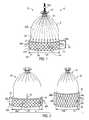
- FIG. 1illustrates a perspective view of an example of a hat structure for holding a pulse oximetry sensor on a tissue of a patient using an annular securing device incorporated into the hat;
- FIG. 2illustrates a perspective view of an example of a hat pulse oximetry sensor before and after being tightened
- FIG. 3illustrates a perspective view of an example of a hat pulse oximetry sensor with an annular securing device incorporated into most of the hat;
- FIG. 4illustrates a perspective view of an example of a hat pulse oximetry sensor with an annular securing device incorporated into a band of the hat;
- FIG. 5illustrates a perspective view of an example of a finger pulse oximetry medical device
- FIG. 6illustrates a perspective view of an example of a foot pulse oximetry medical device
- FIG. 7illustrates a perspective view of an example of a pulse oximetry sensor body
- FIG. 8illustrates a partial cross-sectional view of an example of a hat pulse oximetry sensor
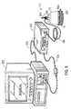
- FIG. 9illustrates an example of a pulse oximetry system coupled to a multi-parameter patient monitor and a sensor.
- Sensors for pulse oximetry or other applications utilizing spectrophotometrymay include the use of an annular securing device to retain a sensor structure on a patient.
- the annular securing devicemay be used in a stocking hat to secure the pulse oximetry sensor on a head of the patient.
- the annular securing devicemay be similar to that used in toys referred to as Chinese finger traps, Chinese finger puzzles, Chinese handcuffs, and so forth. Pulling on one or both ends of the annular securing device in an axial direction may reduce the circumference and diameter of the annular securing device.
- the annular securing devicemay be used in the stocking hat to tighten and conform the stocking hat to the patient, thereby applying a predictable pressure on the sensor.
- the ability of the hat to adapt to different head sizesenables an optimal pressure to be applied by the sensor to the head of the patient.
- Use of various adjustment devices attached to the annular securing devicemay facilitate adjustment of the diameter of the hat.
- a locking or restraining devicemay be provided to maintain a desired diameter of the hat.
- indicia on the hatmay be used to indicate positions of the adjustment devices corresponding to particular head sizes.
- removal devicesmay be provided on the hat to facilitate removal of the hat.
- a caregivermay be able to remove and reapply the hat quickly, saving time for the caregiver.
- the caregivermay place the sensor structure on other areas of the patient including, but not limited to, a finger, a foot, or a limb.
- FIG. 1is a drawing of an adjustable stocking hat 10 in accordance with an embodiment.
- the stocking hat 10includes an annular securing device 24 A that enables the stocking hat 10 to conform to a variety of head sizes.
- the stocking hat 10includes openings at a distal end 12 and a proximal end 14 .
- the annular securing device 24 Ais located in a headband portion 16 of the stocking hat 10 .
- the annular securing device 24 Amay be integral to the stocking hat 10 , such that it is inserted into a pocket formed around the periphery of the stocking hat 10 .
- An upper portion 18 of the stocking hat 10is located above the headband portion 16 .
- a constriction 20Located near the distal end 12 of the stocking hat 10 is a constriction 20 , which is smaller than the opening at the proximal end 14 .
- a distal opening 22Located adjacent to the constriction is a distal opening 22 through which cables, wires, strings, and so forth may pass therethrough.
- a sensor cable or an adjustment device for the annular securing device 24 Amay pass through the distal opening 22 to help direct the cable or device away from the face of patient.
- the annular securing device 24 Amay be constructed from a cylindrical, helically wound braid or a common biaxial braid.
- the annular securing device 24 Amay be constructed by weaving together two perpendicular groups of strands referred to as a warp and a weft.
- the warprefers to the set of lengthwise strands and the weft refers to the strands inserted over and under the strands of the warp.
- the strands of the warp and weftmay be free to move pass one another.
- the increase in the height 26 of the annular securing device 24 Ais obtained by reducing an angle 30 between the warp and weft strands at their crossing points, which reduces the diameter 28 and hence, the overall circumference of the annular securing device 24 A. Additional pulling of the ends of the annular securing device 24 A causes the circumference and the diameter 28 of the annular securing device 24 A to further decrease.
- the strands of the annular securing device 24 Amay be made from materials such as, but not limited to, fabrics, cloths, wood, plastic, metal, and so forth.
- the strandsmay be cloth strips with a width greater than approximately 0.5 cm.
- adjustment devices 32 Amay be attached to the annular securing device 24 A to enable the caregiver to pull the annular securing device 24 A in an axial direction to reduce the circumference of the stocking hat 10 .
- the adjustment devices 32 Amay be attached to individual strands of the annular securing device 24 A.
- the adjustment devices 32 Amay be attached to an annular ring or similar structure attached to the strands of the annular securing device 24 A.
- the adjustment devices 32 Aare strings and are spaced evenly about the annular securing device 24 A. In other embodiments, the spacing of the adjustment devices 32 A may not be regular.
- the number of adjustment devices 32 Amay be selected based on the size of the stocking hat 10 , the amount of force needed to pull on the annular securing device 24 A, the strength of the annular securing device 24 A, adjustment devices 32 A, or connection between the annular securing device 24 A and adjustment devices 32 A, and so forth.
- the adjustment devices 32 Amay include, but are not limited to, strings, threads, filaments, twine, cords, cables, straps, strips, bands, belts, and so forth.
- the adjustment devices 32 Amay be made from natural materials, such as, but not limited to, cotton, linen, hemp, and so forth or synthetic fibers such as, but not limited to, polypropylene, nylon, polyesters, polyethylene, and so forth.
- proximal ends 14 of the adjustment devices 32 Amay be located externally to the stocking hat 10 .
- the adjustment devices 32 Apass through openings 34 in the stocking hat 10 and upper portions of the adjustment devices 32 A, indicated by dashed lines in FIG. 1 , are located internally to the stocking hat 10 .
- Such a configuration of the adjustment devices 32 Amay provide a more pleasing appearance for the stocking hat 10 by reducing the visibility of the adjustment devices 32 A.
- the adjustment devices 32 Amay be routed completely internally to the stocking hat 10 .
- the adjustment devices 32 Amay come together near the distal opening 22 and are routed outside of the stocking hat 10 . Thus, all of the adjustment devices 32 A may be pulled simultaneously to tighten the annular securing device 24 A evenly. In an embodiment, the adjustment devices 32 A may be constrained in the stocking hat 10 to avoid interfering with the eyesight of the patient or bothering the patient.
- a locking device 36 Amay be disposed on the adjustment devices 32 A near the distal opening 22 . After the adjustment devices 32 A are pulled toward the distal end 12 , such that the annular securing device 24 A is tightened to the desired diameter 28 , the locking device 36 A may be slid toward the proximal end 14 and against the constriction 20 to maintain the adjustment devices 32 A in the desired position.
- the locking device 36 Amay be a clip or similar device that uses friction or another restraining force to help prevent the adjustment devices 32 A from moving toward the proximal end 14 , thereby loosening the annular securing device 24 A.
- the locking device 36 Amay be disengaged or moved away from the stocking hat 10 , thereby enabling the adjustment devices 32 A to move toward the proximal end 14 .
- the stocking hat 10may include one or more removal devices 38 A to enable removal of the stocking hat 10 from the patient.
- the removal devices 38 A shown in FIG. 1may be configured as one or more tabs disposed about the perimeter of the annular securing device 24 A. By pulling outward on the removal devices 38 A away from the annular securing device 24 A, the diameter 28 of the stocking hat 10 may be increased enough to enable the stocking hat 10 to slide off the patient.
- the removal devices 38 Amay be made from materials similar to those used for the annular securing device 24 A or the stocking hat 10 .
- the stocking hat 10may also include one or more sensor indicia 40 corresponding to the location of one or more underlying sensors 41 .
- the sensor 41is disposed on an inner surface of the stocking hat 10 and thus, is not visible in FIG. 1 .
- the sensor 41may be a pulse oximetry sensor, or any other type of sensor that may be disposed in the stocking hat 10 .
- the sensor indicia 40may be placed on a patch that is attached to the stocking hat 10 , may be attached directly to the stocking hat 10 , or may be printed on the stocking hat 10 .
- the sensor indicia 40facilitate proper placement of the stocking hat 10 and thus the sensor 41 on the head of the patient. Therefore, coupling the sensor 41 with the stocking hat 10 allows for easy placement of the sensor 41 on the head of the patient while applying a predictable pressure on the sensor 41 using the annular securing device 24 A.
- annular securing device 24 Ais shown exposed in FIG. 1 , it may also be covered.
- the annular securing device 24 Amay be disposed between two layers of fabric that form the inside and outside surfaces of the stocking hat 10 . Such a configuration would help prevent the patient from contacting the annular securing device 24 A.
- such a configuration of the stocking hat 10may help protect the annular securing device 24 A from damage or interference by the patient or other medical equipment.
- covering the annular securing device 24 Amay provide a more pleasing appearance for the stocking hat 10 .
- FIG. 2shows drawings of the stocking hat 10 and how the shape and dimensions of the stocking hat 10 change after the annular securing device 24 A is tightened.
- the stocking hat 10is shown in a relaxed or loosened state 42 .
- the stocking hat 10is shown in a tightened state 44 .
- the top of the annular securing device 24 Ais pulled in the direction of arrow 46 , which may be accomplished using any of the adjustment devices 32 described herein.
- the stocking hat 10has a relaxed height 26 A and a relaxed diameter 28 B.
- the tightened state 44the stocking hat 10 has a tightened height 26 B and a tightened diameter 28 B.
- the tightened height 26 Bis greater than the relaxed height 26 A and the tightened diameter 28 B is less than the relaxed diameter 28 B.
- the angle 30 between the warp and weft strandschanges as the stocking hat 10 is tightened. Specifically, a relaxed angle 30 A is greater than a tightened angle 30 B. In other words, as the angle 30 between the warp and weft strands decreases, the height 26 of the stocking hat 10 increases and the diameter 28 decreases.
- FIG. 3is a drawing of an embodiment of the stocking hat 10 in which the annular securing device 24 B is located in both the headband portion 16 and the upper portion 18 .
- the annular securing device 24 Bmay be useful when used with neonates.
- the caregivermay then fasten the locking device 36 B adjacent to the constriction 20 against the top of the head.
- the locking device 36 Bmay be a clip that includes a plurality of small grips to enable the locking device 36 B to grab the annular securing device 24 B.
- both the locking device 36 B and the constriction 20may be unable to move any further toward the proximal end 14 because of the placement of the locking device 36 B against the head.
- the locking device 36 Bhelps to prevent the annular securing device 24 B from relaxing, thereby maintaining the desired diameter 28 of the stocking hat 10 .
- the locking device 36 Bmay be a rubber band or other similar device to maintain the desired diameter 28 of the stocking hat 10 .
- the locking device 36 Bis removed and the distal end 12 of the stocking hat 10 is allowed to relax toward the patient, thereby loosening the stocking hat 10 .
- the stocking hat 10may include one or more removal devices 38 B attached to the perimeter of the headband portion 16 .
- the removal devices 38 Bare configured as loops that may be used in a manner similar to the removal devices 38 A shown in FIG. 1 . Specifically, the caregiver may insert a finger into the removal device 38 B and pull outward and away from the patient to enable removal of the stocking hat 10 without causing the stocking hat 10 to tighten.
- FIG. 4shows a drawing of the stocking hat 10 in which one or more adjustment devices 32 B may be attached to the annular securing device 24 A and pulled in an axial direction to tighten the annular securing device 24 A and reduce the diameter of the stocking hat 10 .
- the adjustment devices 32 Bare configured as tabs or strips attached to individual strands of the annular securing device 24 A or to a ring or similar structure attached to the strands of the annular securing device 24 A.
- the number of adjustment devices 32 Bmay be less than that of the adjustment devices 32 A shown in FIG. 1 because the adjustment devices 32 B may be wider and stronger.
- the manufacture of stocking hats 10 using the adjustment devices 32 Bmay be less complicated and/or less costly than that of stocking hats 10 using the adjustment devices 32 A shown in FIG. 1 . Further, the adjustment devices 32 B may be less likely to be interfered with by the patient.
- the distal ends 12 of the adjustment devices 32 Binclude a hook side 72 of a hook and loop fastener.
- the upper portion 18 of the stocking hat 10may include a loop side 73 of the hook and loop fastener opposite the hook side 72 .
- the material used for the stocking hat 10may function as the loop side 73 of the hook and loop fastener.
- the adjustment devices 32 Bare pulled in the direction of the distal end 12 of the stocking hat 10 and the hook sides 72 fastened to the loop sides 73 .
- the hook sides 72 of the adjustment devices 32 Bare removed from the loop sides 73 .
- the adjustment devices 32 Bmay be made from materials similar to those used for the stocking hat 10 .
- one or more adjustment indicia 74may be provided on the upper portion 18 of the stocking hat 10 .
- the adjustment indicia 74may include, but are not limited to, lines, marks, symbols, and so forth, to correspond to one or more head sizes of the patients using the stocking hat 10 .
- adjustment indicia 74 located near the proximal end 14may correspond to larger head sizes and adjustment indicia 74 located near the distal end 12 may correspond to smaller head sizes.
- the adjustment indicia 74may facilitate tightening the stocking hat 10 to exert the proper pressure on the pulse oximeter sensor 41 for a particular patient.
- part of the upper portion 18 of the stocking hat 10may also include the annular securing device 24 B.
- the adjustment devices 32 Bmay be attached to the top of the annular securing device 24 B located in the upper portion 18 .
- devicessuch as, but not limited to, snaps, buttons, and other fasteners, may be used to secure the adjustment devices 32 B to the stocking hat 10 .
- the removal device 38 Amay be attached to part of the sensor index 40 . Such a location for the removal device 38 A may enable the caregiver to locate the removal device 38 A quicker. In addition, it may be simpler to attach the removal devices 38 A to the sensor indicia 40 instead of directly to the annular securing device 24 A.
- the sensor indicia 40may include raised components that enable the sensor indicia 40 to function as the removal devices 38 . Specifically, a caregiver may be able to grasp the raised component of a sensor index 40 to remove the stocking hat 10 without causing the annular securing device 24 A to tighten.
- one or more removal devices 38 Bsuch as the loops shown in FIG. 3 , may be attached to the sensor indicia 40 or the headband portion 16 to facilitate removal of the stocking hat 10 .
- FIG. 5shows a drawing of a finger pulse oximetry medical device 110 disposed on a finger 112 of a patient.
- the sensor 41may be placed on the finger 112 when the head is injured, to avoid patient discomfort, or to reduce the possibility of inadvertent removal.
- the medical device 110is constructed and operated in a manner similar to the stocking hat 10 described in detail above.
- the band portion 16 of the medical device 110may include the annular securing device 24 A and the pulse oximetry sensor 41 .
- One or more adjustment devices 32 Amay be attached to the annular securing device 24 A, routed through the constriction 20 , and exit through the distal opening 22 .
- the adjustment devices 32 AWhen the adjustment devices 32 A are pulled away from the finger 112 , the diameter 28 of the medical device 110 decreases, conforming the medical device 110 to the finger 112 .
- the adjustment devices 32 Aare routed completely through the interior of the medical device 110 .
- the locking device 36 Amay be used to secure the annular securing device 24 A in a tightened position around the finger 112 .
- the band portion 16may be positioned away from a nail 114 of the finger 112 to enable more accurate pulse oximetry measurements.
- the medical device 110may be released from the finger 112 be either removing the locking device 36 A or pulling on the removal devices 38 A in a direction away from the finger 112 .
- the medical device 110may be positioned on a toe of the patient.
- the medical device 110may include the annular securing device 24 B and locking device 36 B such that generally all of the medical device 110 is conformable to the finger 112 . Such a configuration may reduce the possibility of inadvertent removal of the medical device 110 .
- the pulse oximetry sensor 41may also be placed on a foot 132 .
- the band portion 16 of a foot pulse oximetry medical device 130may include the annular securing device 24 A. Placing the medical device 130 on the foot 132 may be useful if other locations are unavailable, injured, or inconvenient for the patient.
- the medical device 130is similar to the stocking hat 10 described in FIG. 1 . Specifically, pulling on the adjustment devices 32 A away from the foot 132 results in a decrease in the diameter 28 of the medical device 130 , conforming the medical device 130 to the foot 132 .
- the medical device 130may be configured similar to the stocking hats 10 shown in FIG. 3 or 4 .
- the medical device 130covers a foot 132 of the patient instead of being disposed on individual toes 134 .
- the medical device 130uses removal devices 38 B configured as loops as one option for removing the medical device 130 from the foot 132 .
- pulling on tabs, such as removal devices 38 A, or removal of the locking device 36 Amay be used to remove the medical device 130 .
- a reflectance-type pulse oximetry sensor 41may be placed or adhered to the inside of the stocking hat 10 .
- Examples of such a sensor 41 and its use and constructionmay be found in U.S. Pat. No. 7,047,056, which issued on May 16, 2006, as well as U.S. Pat. No. 7,809,420, which issued on Oct. 5, 2010, which are both herein incorporated by reference in their entirety for all purposes.
- the sensor 41may include a substrate 182 that may be made from any suitable material. In an embodiment, the substrate 182 is a foam or other conformable material.
- the substrate 182is black or dark in color to absorb stray light and minimize any shunting of light between the sensor 41 and the patient skin.
- the substrate 182may include an adhesive material to secure the sensor 41 directly to the tissue.
- the sensor 41may include an emitter 184 containing emitters for two or more wavelengths of lights and a detector 186 spaced apart from the emitter 184 .
- a cable 188for providing drive current to the emitter 184 , and providing the detector signal to a medical device.
- the cable 188may provide shielding to protect the small signals from the detector 186 against external electrical interference.
- the sensor 41may include suitable structures for providing electrical connections to the cable 188 and/or downstream medical device, such as a flex circuit, a Faraday shield, and leads connecting the optical components of the sensor 41 to the electrical components.
- the sensor assembly 41is shown fully assembled together with the stocking hat 10 in FIG. 8 . As shown, the sensor 41 is positioned on the interior of the stocking hat 10 such that the emitter 184 and detector 186 may come into contact with the skin when the stocking hat 10 is applied to the patient. The sensor 41 may be attached (e.g., adhered or sewn into) to the inside band of the stocking hat 10 .
- the stocking hat 10may include indicators, such as the sensor indicia 40 described above, to position the sensor 41 on a particular location on the forehead of the patient, for example to position the sensor 41 on the lower forehead region, above the eyebrow, with the sensor optics (emitter 184 and detector 186 ) located above and predominantly lateral to or centered over the iris.
- the location of the reflectance sensor 41 in the stocking hat 10allows appropriate placement of the sensor 41 in the desired forehead location by a user not skilled in sensor placement.
- FIG. 8shows that the cable 188 is positioned through the distal opening 22 in the top of the stocking hat 10 .
- the cable 188may be adhered or otherwise constrained in the stocking hat 10 so that the cable 188 generally is positioned away from the sensor 41 to avoid interfering with the eyesight of the patient or bothering the patient.
- a sensor or sensor assemblymay be used in conjunction with a pulse oximetry monitor 220 , as illustrated in FIG. 9 .
- the cable 188 of the stocking hat 10may be coupled to the monitor 220 or it may be coupled to a transmission device to facilitate wireless transmission between the stocking hat 10 and the monitor 220 .
- the monitor 220may be any suitable pulse oximeter, such as those available from Nellcor Puritan Bennett LLC.
- the monitor 220may be coupled to a multi-parameter patient monitor 222 via a cable 224 connected to a sensor input port or via a cable 226 connected to a digital communication port.
Landscapes
- Health & Medical Sciences (AREA)
- Life Sciences & Earth Sciences (AREA)
- General Health & Medical Sciences (AREA)
- Engineering & Computer Science (AREA)
- Public Health (AREA)
- Biomedical Technology (AREA)
- Veterinary Medicine (AREA)
- Animal Behavior & Ethology (AREA)
- Heart & Thoracic Surgery (AREA)
- Vascular Medicine (AREA)
- Surgery (AREA)
- Molecular Biology (AREA)
- Dentistry (AREA)
- Radiology & Medical Imaging (AREA)
- Medical Informatics (AREA)
- Biophysics (AREA)
- Pathology (AREA)
- Oral & Maxillofacial Surgery (AREA)
- Physics & Mathematics (AREA)
- Optics & Photonics (AREA)
- Epidemiology (AREA)
- Nuclear Medicine, Radiotherapy & Molecular Imaging (AREA)
- Physical Education & Sports Medicine (AREA)
- Textile Engineering (AREA)
- Measurement Of The Respiration, Hearing Ability, Form, And Blood Characteristics Of Living Organisms (AREA)
Abstract
Description
Claims (20)
Priority Applications (1)
| Application Number | Priority Date | Filing Date | Title |
|---|---|---|---|
| US13/035,611US9049893B2 (en) | 2011-02-25 | 2011-02-25 | Device for securing a medical sensor |
Applications Claiming Priority (1)
| Application Number | Priority Date | Filing Date | Title |
|---|---|---|---|
| US13/035,611US9049893B2 (en) | 2011-02-25 | 2011-02-25 | Device for securing a medical sensor |
Publications (2)
| Publication Number | Publication Date |
|---|---|
| US20120216335A1 US20120216335A1 (en) | 2012-08-30 |
| US9049893B2true US9049893B2 (en) | 2015-06-09 |
Family
ID=46717998
Family Applications (1)
| Application Number | Title | Priority Date | Filing Date |
|---|---|---|---|
| US13/035,611Expired - Fee RelatedUS9049893B2 (en) | 2011-02-25 | 2011-02-25 | Device for securing a medical sensor |
Country Status (1)
| Country | Link |
|---|---|
| US (1) | US9049893B2 (en) |
Families Citing this family (10)
| Publication number | Priority date | Publication date | Assignee | Title |
|---|---|---|---|---|
| US9161722B2 (en) | 2011-09-07 | 2015-10-20 | Covidien Lp | Technique for remanufacturing a medical sensor |
| US9220436B2 (en) | 2011-09-26 | 2015-12-29 | Covidien Lp | Technique for remanufacturing a BIS sensor |
| US8852095B2 (en) | 2011-10-27 | 2014-10-07 | Covidien Lp | Headband for use with medical sensor |
| US9138181B2 (en) | 2011-12-16 | 2015-09-22 | Covidien Lp | Medical sensor for use with headband |
| EP3413957B1 (en)* | 2016-02-08 | 2020-11-18 | West Pharmaceutical Services, Inc. | Needle shield puller |
| KR102359218B1 (en)* | 2017-05-01 | 2022-02-07 | 에스에이치엘 메디컬 아게 | needle shield remover |
| CN107320079A (en)* | 2017-08-08 | 2017-11-07 | 成都华蓉领创科技有限公司 | A kind of home medical monitoring system based on Internet of Things |
| WO2020061119A1 (en)* | 2018-09-17 | 2020-03-26 | Omius Inc. | Dermal heatsink exhibiting hydrophilic and contaminant resistant properties and method for fabricating a dermal heatsink |
| US12098890B2 (en) | 2018-09-17 | 2024-09-24 | Omius Inc. | Evaporative cooling system |
| US11666256B2 (en) | 2020-10-27 | 2023-06-06 | Michael Edward Labrecque | Pulse oximeter sensor |
Citations (51)
| Publication number | Priority date | Publication date | Assignee | Title |
|---|---|---|---|---|
| US1304215A (en) | 1919-05-20 | Sweat-baud protector | ||
| US1899020A (en) | 1932-05-26 | 1933-02-28 | Bernhard J Drueding | Hat |
| US3872861A (en) | 1973-08-20 | 1975-03-25 | Simon Tamny | Contractable finger trap |
| US4035846A (en)* | 1976-08-17 | 1977-07-19 | The United States Of America As Represented By The Secretary Of The Navy | Inflatable pressure compensated helmet stabilization system |
| US4321930A (en) | 1977-06-28 | 1982-03-30 | Duke University, Inc. | Apparatus for monitoring metabolism in body organs |
| EP0127947A2 (en) | 1983-05-11 | 1984-12-12 | Nellcor Incorporated | Sensor having cutaneous conformance |
| DE3516338A1 (en) | 1985-05-07 | 1986-11-13 | Drägerwerk AG, 2400 Lübeck | Mounting for a measurement sensor |
| EP0204259A1 (en) | 1985-06-01 | 1986-12-10 | Alcatel SEL Aktiengesellschaft | Two-frequency instrument-landing system |
| DE3703458A1 (en) | 1987-02-05 | 1988-08-18 | Hewlett Packard Gmbh | Medical oxygen saturation sensor using electromagnetic waves - has support segment for transmitter and receiver elements and clamping segment for fitting round patent |
| US5040540A (en) | 1988-08-24 | 1991-08-20 | Nims, Inc. | Method and apparatus for non-invasive monitoring of central venous pressure, and improved transducer therefor |
| EP0531631A1 (en) | 1991-06-19 | 1993-03-17 | Endotronics, Inc. | Cell culture apparatus |
| US5217013A (en) | 1983-10-14 | 1993-06-08 | Somanetics Corporation | Patient sensor for optical cerebral oximeter and the like |
| FR2685865A1 (en) | 1992-01-08 | 1993-07-09 | Distr App Medicaux Off | Optical sensor, especially for measuring the oxygen saturation level in arterial blood |
| US5246003A (en) | 1991-08-28 | 1993-09-21 | Nellcor Incorporated | Disposable pulse oximeter sensor |
| US5267563A (en) | 1991-06-28 | 1993-12-07 | Nellcor Incorporated | Oximeter sensor with perfusion enhancing |
| JPH0614906A (en) | 1992-06-30 | 1994-01-25 | Minolta Camera Co Ltd | Probe for living body information measurement |
| US5369808A (en) | 1993-06-04 | 1994-12-06 | Brewer; Dale A. | Hat with snug fitting arcuate hat band |
| WO1995002358A1 (en) | 1993-07-14 | 1995-01-26 | Masimo Corporation | Finger cot oximetric probe |
| US5431170A (en) | 1990-05-26 | 1995-07-11 | Mathews; Geoffrey R. | Pulse responsive device |
| US5465714A (en) | 1993-05-20 | 1995-11-14 | Somanetics Corporation | Electro-optical sensor for spectrophotometric medical devices |
| US5482034A (en) | 1993-05-28 | 1996-01-09 | Somanetics Corporation | Method and apparatus for spectrophotometric cerebral oximetry and the like |
| US5496257A (en) | 1994-04-22 | 1996-03-05 | Kelly Medical Products, Inc. | Apparatus for assisting in the application of cardiopulmonary resuscitation |
| US5507752A (en) | 1990-09-06 | 1996-04-16 | Board Of Regents, The University Of Texas System | Obstetric bonnet for assisting childbirth and method of manufacturing the same |
| US5584296A (en) | 1992-12-01 | 1996-12-17 | Somanetics Corporation | Patient sensor for optical cerebral oximeters and the like |
| DE19632361A1 (en) | 1995-08-17 | 1997-02-20 | Tunturipyoerae Oy | sensor |
| WO1997036536A1 (en) | 1996-04-03 | 1997-10-09 | Vista Medical Technologies, Inc. | Optical female urethroscope |
| US5817008A (en) | 1996-10-31 | 1998-10-06 | Spacelabs Medical, Inc. | Conformal pulse oximetry sensor and monitor |
| US5910146A (en) | 1990-05-14 | 1999-06-08 | Medisys Technologies, Inc. | Device for assisting childbirth |
| US5931789A (en) | 1996-03-18 | 1999-08-03 | The Research Foundation City College Of New York | Time-resolved diffusion tomographic 2D and 3D imaging in highly scattering turbid media |
| US5995857A (en) | 1996-07-01 | 1999-11-30 | Toomim; I. Hershel | Biofeedback of human central nervous system activity using radiation detection |
| US20020103520A1 (en) | 1998-12-18 | 2002-08-01 | Latham Jeffrey Wade | Therapeutic cooling devices |
| US6456862B2 (en) | 2000-05-02 | 2002-09-24 | Cas Medical Systems, Inc. | Method for non-invasive spectrophotometric blood oxygenation monitoring |
| US20020165462A1 (en) | 2000-12-29 | 2002-11-07 | Westbrook Philip R. | Sleep apnea risk evaluation |
| US6553242B1 (en) | 1997-06-15 | 2003-04-22 | S.P.O. Medical Equipment Ltd. | Physiological stress detector device and method |
| US6577884B1 (en) | 2000-06-19 | 2003-06-10 | The General Hospital Corporation | Detection of stroke events using diffuse optical tomagraphy |
| US20030109775A1 (en) | 2001-10-12 | 2003-06-12 | Nellcor Puritan Bennett Inc. | Stacked adhesive optical sensor |
| US6615065B1 (en) | 1998-10-13 | 2003-09-02 | Somanetics Corporation | Multi-channel non-invasive tissue oximeter |
| US6626537B1 (en) | 2001-05-18 | 2003-09-30 | West Virginia University | Non-invasive ocular dynamic monitoring assessment method and associated apparatus |
| US20030225323A1 (en) | 2002-01-08 | 2003-12-04 | Kiani Massi E. | Physiological sensor combination |
| US20030229276A1 (en) | 2000-02-01 | 2003-12-11 | Israel Sarussi | Physiological stress detector device and system |
| US20040018422A1 (en) | 2002-07-24 | 2004-01-29 | Islam Quazi Towhidul | Device including flexible battery and method of producing same |
| US20050113655A1 (en) | 2003-11-26 | 2005-05-26 | Hull Drue A. | Wireless pulse oximeter configured for web serving, remote patient monitoring and method of operation |
| US20050233707A1 (en) | 2004-04-16 | 2005-10-20 | Hon Hai Precision Industry Co., Ltd | Mobile phone with health care functionality |
| US7047056B2 (en) | 2003-06-25 | 2006-05-16 | Nellcor Puritan Bennett Incorporated | Hat-based oximeter sensor |
| US20060248946A1 (en) | 2004-12-20 | 2006-11-09 | Howell Thomas A | Moisture sensor for skin |
| US20080143080A1 (en) | 2006-10-27 | 2008-06-19 | Textronics, Inc. | Wearable article with band portion adapted to include textile-based electrodes and method of making such article |
| US20080173719A1 (en) | 2007-01-19 | 2008-07-24 | Chein-Hsun Wang | Temperature management in an integrated circuit card with electrophoretic display |
| US7582109B2 (en) | 2004-08-04 | 2009-09-01 | Delegge Rebecca | Thermal transition methods and devices |
| US7721349B1 (en)* | 2005-06-25 | 2010-05-25 | Ted Nathan Strauss | Flexible personal evaporative cooling system with warming potential |
| US8452367B2 (en)* | 2002-10-01 | 2013-05-28 | Covidien Lp | Forehead sensor placement |
| US8483790B2 (en)* | 2002-10-18 | 2013-07-09 | Covidien Lp | Non-adhesive oximeter sensor for sensitive skin |
- 2011
- 2011-02-25USUS13/035,611patent/US9049893B2/ennot_activeExpired - Fee Related
Patent Citations (56)
| Publication number | Priority date | Publication date | Assignee | Title |
|---|---|---|---|---|
| US1304215A (en) | 1919-05-20 | Sweat-baud protector | ||
| US1899020A (en) | 1932-05-26 | 1933-02-28 | Bernhard J Drueding | Hat |
| US3872861A (en) | 1973-08-20 | 1975-03-25 | Simon Tamny | Contractable finger trap |
| US4035846A (en)* | 1976-08-17 | 1977-07-19 | The United States Of America As Represented By The Secretary Of The Navy | Inflatable pressure compensated helmet stabilization system |
| US4321930A (en) | 1977-06-28 | 1982-03-30 | Duke University, Inc. | Apparatus for monitoring metabolism in body organs |
| EP0127947A2 (en) | 1983-05-11 | 1984-12-12 | Nellcor Incorporated | Sensor having cutaneous conformance |
| US5217013A (en) | 1983-10-14 | 1993-06-08 | Somanetics Corporation | Patient sensor for optical cerebral oximeter and the like |
| DE3516338A1 (en) | 1985-05-07 | 1986-11-13 | Drägerwerk AG, 2400 Lübeck | Mounting for a measurement sensor |
| EP0204259A1 (en) | 1985-06-01 | 1986-12-10 | Alcatel SEL Aktiengesellschaft | Two-frequency instrument-landing system |
| DE3703458A1 (en) | 1987-02-05 | 1988-08-18 | Hewlett Packard Gmbh | Medical oxygen saturation sensor using electromagnetic waves - has support segment for transmitter and receiver elements and clamping segment for fitting round patent |
| US5040540A (en) | 1988-08-24 | 1991-08-20 | Nims, Inc. | Method and apparatus for non-invasive monitoring of central venous pressure, and improved transducer therefor |
| US5910146A (en) | 1990-05-14 | 1999-06-08 | Medisys Technologies, Inc. | Device for assisting childbirth |
| US5431170A (en) | 1990-05-26 | 1995-07-11 | Mathews; Geoffrey R. | Pulse responsive device |
| US5507752A (en) | 1990-09-06 | 1996-04-16 | Board Of Regents, The University Of Texas System | Obstetric bonnet for assisting childbirth and method of manufacturing the same |
| EP0531631A1 (en) | 1991-06-19 | 1993-03-17 | Endotronics, Inc. | Cell culture apparatus |
| US5267563A (en) | 1991-06-28 | 1993-12-07 | Nellcor Incorporated | Oximeter sensor with perfusion enhancing |
| US5246003A (en) | 1991-08-28 | 1993-09-21 | Nellcor Incorporated | Disposable pulse oximeter sensor |
| FR2685865A1 (en) | 1992-01-08 | 1993-07-09 | Distr App Medicaux Off | Optical sensor, especially for measuring the oxygen saturation level in arterial blood |
| JPH0614906A (en) | 1992-06-30 | 1994-01-25 | Minolta Camera Co Ltd | Probe for living body information measurement |
| US5584296A (en) | 1992-12-01 | 1996-12-17 | Somanetics Corporation | Patient sensor for optical cerebral oximeters and the like |
| US5465714A (en) | 1993-05-20 | 1995-11-14 | Somanetics Corporation | Electro-optical sensor for spectrophotometric medical devices |
| US5482034A (en) | 1993-05-28 | 1996-01-09 | Somanetics Corporation | Method and apparatus for spectrophotometric cerebral oximetry and the like |
| US5369808A (en) | 1993-06-04 | 1994-12-06 | Brewer; Dale A. | Hat with snug fitting arcuate hat band |
| WO1995002358A1 (en) | 1993-07-14 | 1995-01-26 | Masimo Corporation | Finger cot oximetric probe |
| US5496257A (en) | 1994-04-22 | 1996-03-05 | Kelly Medical Products, Inc. | Apparatus for assisting in the application of cardiopulmonary resuscitation |
| DE19632361A1 (en) | 1995-08-17 | 1997-02-20 | Tunturipyoerae Oy | sensor |
| US5931789A (en) | 1996-03-18 | 1999-08-03 | The Research Foundation City College Of New York | Time-resolved diffusion tomographic 2D and 3D imaging in highly scattering turbid media |
| WO1997036536A1 (en) | 1996-04-03 | 1997-10-09 | Vista Medical Technologies, Inc. | Optical female urethroscope |
| US5995857A (en) | 1996-07-01 | 1999-11-30 | Toomim; I. Hershel | Biofeedback of human central nervous system activity using radiation detection |
| US5817008A (en) | 1996-10-31 | 1998-10-06 | Spacelabs Medical, Inc. | Conformal pulse oximetry sensor and monitor |
| US6553242B1 (en) | 1997-06-15 | 2003-04-22 | S.P.O. Medical Equipment Ltd. | Physiological stress detector device and method |
| US6615065B1 (en) | 1998-10-13 | 2003-09-02 | Somanetics Corporation | Multi-channel non-invasive tissue oximeter |
| US20020103520A1 (en) | 1998-12-18 | 2002-08-01 | Latham Jeffrey Wade | Therapeutic cooling devices |
| US20030229276A1 (en) | 2000-02-01 | 2003-12-11 | Israel Sarussi | Physiological stress detector device and system |
| US6456862B2 (en) | 2000-05-02 | 2002-09-24 | Cas Medical Systems, Inc. | Method for non-invasive spectrophotometric blood oxygenation monitoring |
| US6577884B1 (en) | 2000-06-19 | 2003-06-10 | The General Hospital Corporation | Detection of stroke events using diffuse optical tomagraphy |
| US20020165462A1 (en) | 2000-12-29 | 2002-11-07 | Westbrook Philip R. | Sleep apnea risk evaluation |
| US6626537B1 (en) | 2001-05-18 | 2003-09-30 | West Virginia University | Non-invasive ocular dynamic monitoring assessment method and associated apparatus |
| US20030109775A1 (en) | 2001-10-12 | 2003-06-12 | Nellcor Puritan Bennett Inc. | Stacked adhesive optical sensor |
| US20030225323A1 (en) | 2002-01-08 | 2003-12-04 | Kiani Massi E. | Physiological sensor combination |
| US20040018422A1 (en) | 2002-07-24 | 2004-01-29 | Islam Quazi Towhidul | Device including flexible battery and method of producing same |
| US8452367B2 (en)* | 2002-10-01 | 2013-05-28 | Covidien Lp | Forehead sensor placement |
| US8483790B2 (en)* | 2002-10-18 | 2013-07-09 | Covidien Lp | Non-adhesive oximeter sensor for sensitive skin |
| US7809420B2 (en) | 2003-06-25 | 2010-10-05 | Nellcor Puritan Bennett Llc | Hat-based oximeter sensor |
| US7047056B2 (en) | 2003-06-25 | 2006-05-16 | Nellcor Puritan Bennett Incorporated | Hat-based oximeter sensor |
| US20060195028A1 (en) | 2003-06-25 | 2006-08-31 | Don Hannula | Hat-based oximeter sensor |
| US7877126B2 (en) | 2003-06-25 | 2011-01-25 | Nellcor Puritan Bennett Llc | Hat-based oximeter sensor |
| US7877127B2 (en) | 2003-06-25 | 2011-01-25 | Nellcor Puritan Bennett Llc | Hat-based oximeter sensor |
| US7813779B2 (en) | 2003-06-25 | 2010-10-12 | Nellcor Puritan Bennett Llc | Hat-based oximeter sensor |
| US20050113655A1 (en) | 2003-11-26 | 2005-05-26 | Hull Drue A. | Wireless pulse oximeter configured for web serving, remote patient monitoring and method of operation |
| US20050233707A1 (en) | 2004-04-16 | 2005-10-20 | Hon Hai Precision Industry Co., Ltd | Mobile phone with health care functionality |
| US7582109B2 (en) | 2004-08-04 | 2009-09-01 | Delegge Rebecca | Thermal transition methods and devices |
| US20060248946A1 (en) | 2004-12-20 | 2006-11-09 | Howell Thomas A | Moisture sensor for skin |
| US7721349B1 (en)* | 2005-06-25 | 2010-05-25 | Ted Nathan Strauss | Flexible personal evaporative cooling system with warming potential |
| US20080143080A1 (en) | 2006-10-27 | 2008-06-19 | Textronics, Inc. | Wearable article with band portion adapted to include textile-based electrodes and method of making such article |
| US20080173719A1 (en) | 2007-01-19 | 2008-07-24 | Chein-Hsun Wang | Temperature management in an integrated circuit card with electrophoretic display |
Non-Patent Citations (40)
| Title |
|---|
| "Smaller Product, Tighter Tolerances Pose Dispensing Challenges for Medical Device Manufacturer," Adhesives Age, pp. 40-41 (Oct. 1997). |
| Avidan, A.; "Pulse oximeter ear probe," Anaesthesia, vol. 58, pp. 726 (2003). |
| Bentley, D. et al.; "Measure Pressure with Thin Film," Paper Film & Foil Converter; May 1, 2003 (4 pages). |
| Branche, P., et al.; "Measurement Reproducibility and Sensor Placement Considerations in Designing a Wearable Pulse Oximeter for Military Applications," 2 pgs. (2004). |
| Crilly, P., et al.; "An Integrated Pulse Oximeter System for Telemedicine Applications," IEEE Instrumentation and Measurement Technology Conference, Ottawa, Canada; May 19-21, 1997; pp. 102-104. |
| Dekock, M.; "Pulse Oximetry Probe Adhesive Disks: a Potential for Infant Aspiration," Anesthesiology, vol. 89, pp. 1603-1604 (1998). |
| Dresher, R., in "Wearable Forehead Pulse Oximetry: Minimization of Motion and Pressure Artifacts" A Thesis Submitted to the Faculty of the Worcester Polytechnic Institute in partial fulfillment of the requirements for the Degree of Master of Science, May 3, 2006, p. 1-93. |
| Earthrowl-Gould, T., et al.; "Chest and abdominal surface motion measurement for continuous monitoring of respiratory function," Proc. Instn Mech Engrs, V215, Part H; pp. 515-520 (2001). |
| Faisst, K., et al.; "Intrapartum Reflectance Pulse Oximetry: Effects of Sensor Location and Fixation Duration on Oxygen Saturation Readings," Journal of Clinical Monitoring, vol. 13, pp. 299-302 (1997). |
| Ferrell, T.L., et al.; "Medical Telesensors," SPIE, vol. 3253, pp. 193-198 (1998). |
| Gisiger, P.A., et al.; "OxiCarbo®, a single sensor for the non-invasive measurement of arterial oxygen saturation and CO2 partial pressure at the ear lobe," Sensor and Actuators, vol. B-76, pp. 527-530 (2001). |
| Gosney, S., et al.; "An alternative position for the pulse oximeter probe," Anaesthesia, vol. 56, p. 493 (2001). |
| Hayoz, J., et al.; "World's First Combined digital Pulse Oximetry Pulse Oximetry and Carbon Dioxide Tension Ear Sensor", Abstracts, A6, p. S103. (undated). |
| Heuss, L., et al.; "Combined Pulse Oximetry / Cutaneous Carbon dioxide Tension Monitoring During Colonoscopies: Pilot study with a Smart Ear Clip," Digestion, vol. 70, pp. 152-158 (2004). |
| http://www.cfw.com.my/fujifilm.html (4 pages). |
| Irie, A., et al.; "Respiration Monitors-Pulse Oximeters," Neonatal Care, vol. 15, No. 12, pp. 78-83 (2002) (Article in Japanese-contains English summary of article). |
| Izumi, A., et al.; "Accuracy and Utility of a New Reflectance Pulse Oximeter for Fetal Monitoring During Labor," Journal of Clinical Monitoring, vol. 13, pp. 103-108 (1997). |
| Johnston, W., et al.; "Effects of Motion Artifacts on helmet-Mounted Pulse Oximeter Sensors," 2 pgs. (2004). |
| Kocher, S., et al.; "Performance of a Digital PCO2/SPO2 Ear Sensor," Journal of Clinical Monitoring and Computing, vol. 18, pp. 75-59 (2004). |
| Kyriacou, P. A., et al.; "Esophageal Pulse Oximetry Utilizing Reflectance Photoplethysmography," IEEE Transactions on Biomedical Engineering, vol. 49, No. 11, pp. 1360-1368 (Nov. 2002). |
| Kyriacou, P. A., et al.; "Investigation of esophageal photoplethysmographic signals and blood oxygen saturation measurements in cardiothoracic surgery patients," Physiological Measurement, vol. 23, No. 3, pp. 533-545 (Aug. 2002). |
| Maletras, F., et al.; "Construction and calibration of a new design of Fiber Optic Respiratory Plethysmograph (FORP)," Optomechanical Design and Engineering, Proceedings of SPIE, vol. 4444, pp. 285-293 (2001). |
| Mannheimer, P., et al.; "The influence of Larger Subcutaneous Blood Vessels on Pulse Oximetry," Journal of clinical Monitoring and Computing, vol. 18, pp. 179-188 (2004). |
| Matsui, A., et al.; "Pulse Oximeter," Neonatal Care, vol. 16, No. 3, pp. 38-45 (2003) (Article in Japanese-contains English summary of article). |
| Nakagawa, M., et al.; "Oxygen Saturation Monitor," Neonatal Monitoring, vol. 26, No. 5, pp. 536-539 (2003) (Article in Japanese-contains English summary of article). |
| Rhee, S., et al.; "Artifact-Resistant, Power-Efficient Design of Finger-Ring Plethysmographic Sensor," IEEE Transactions on Biomedical Engineering, vol. 48, No. 7, pp. 795-805 (Jul. 2001). |
| Rhee, S., et al.; "Artifact-Resistant, Power-Efficient Design of Finger-Ring Plethysmographic Sensor-Part I: Design and Analysis," Proceedings of the 22nd Annual EMBS International Conference, Chicago, Illinois; Jul. 23-28, 2000; pp. 2792-2795. |
| Rhee, S., et al.; "Artifact-Resistant, Power-Efficient Design of Finger-Ring Plethysmographic Sensor-Part II: Prototyping and Benchmarking," Proceedings of the 22nd Annual EMBS International Conference, Chicago, Illinois; Jul. 23-28, 2000; pp. 2796. |
| Rhee, S., et al.; "The Ring Sensor: a New Ambulatory Wearable Sensor for Twenty-Four Hour Patient Monitoring," Proceedings of the 20th annual International Conference of the IEEE Engineering in Medicine and Biology Society, 1998, vol. 20, No. 4, pp. 1906-1919. |
| Rohling, R., et al.; "Clinical Investigation of a New Combined Pulse Oximetry and Carbon Dioxide Tension Sensor in Adult Anaesthesia," Journal of Clinical Monitoring and Computing, vol. 15; pp. 23-27 (1999). |
| Schulz, C.; "Design of a Pulse Oximetry Sensor Housing Assembly," California State University Master's Thesis, UMI Dissertation Services, UMI No. 1401306, (May 2000) 63 pages. |
| Shaltis, P., et al.; "Implementation and Validation of a Power-Efficient, High-Speed Modulation Design for Wireless Oxygen Saturation Measurement Systems," IEEE, pp. 193-194 (2002). |
| Soto, D.; "A Comparative Study of Pulse Oximeter Measurements: Digit Versus Earlobe," Master of Science Thesis, California State University Dominguez Hills, May 1997, 46 pgs. |
| Sugino, S., et al.; "Forehead is as sensitive as finger pulse oximetry during general anesthesia," Can J. Anesth.; General Anesthesia, vol. 51, No. 5; pp. 432-436 (2004). |
| Urquhart, C., et al.; "Ear probe pulse oximeters and neonates," Anaesthesia, vol. 60, p. 294 (2005). |
| Warren, S., et al.; "Wearable Sensors and Component-Based Design for Home Health Care," Proceedings of the Second Joint EMBS/BMES Conference, Houston, Texas; Oct. 23-26, 2002; pp. 1871-1872. |
| Wendelken, S., et al.; "The Feasibility of Using a Forehead Reflectance Pulse Oximeter for Automated Remote Triage," IEEE, pp. 180-181 (2004). |
| Yang, B., et al.; "A Twenty-Four Hour Tele-Nursing System Using a Ring Sensor," Proceedings of the 1998 IEEE International Conference on Robotics & Automation, Leaven, Belgium, May 1998; pp. 387-392. |
| Yang, B., et al.; "Development of the ring sensor for healthcare automation," Robotics and Autonomous Systems, vol. 30, pp. 273-281 (2000). |
| Yokota, N., et al.; "Pilot Model of a Reflectance-Type Pulse Oximeter for Pre-hospital Evaluation," Journal of the Japanese Society of Emergency Medicine, Kanto Region, vol. 21, pp. 26-27 (2000) (Article in Japanese-contains English summary. |
Also Published As
| Publication number | Publication date |
|---|---|
| US20120216335A1 (en) | 2012-08-30 |
Similar Documents
| Publication | Publication Date | Title |
|---|---|---|
| US9049893B2 (en) | Device for securing a medical sensor | |
| US8852095B2 (en) | Headband for use with medical sensor | |
| US20210015365A1 (en) | Optical tomography sensor and related apparatus and methods | |
| US8326392B2 (en) | Foldable sensor device and method of using same | |
| US8417309B2 (en) | Medical sensor | |
| US7047056B2 (en) | Hat-based oximeter sensor | |
| US8396527B2 (en) | Medical sensor for reducing signal artifacts and technique for using the same | |
| US8195264B2 (en) | Medical sensor for reducing signal artifacts and technique for using the same | |
| EP1718195B1 (en) | Headband with tension indicator | |
| US7758526B2 (en) | Hand and digit immobilizer for pulse oximeter | |
| US8577436B2 (en) | Medical sensor for reducing signal artifacts and technique for using the same | |
| US8175671B2 (en) | Medical sensor for reducing signal artifacts and technique for using the same | |
| CN107847190B (en) | Device for holding a physiological sensor | |
| US20100081904A1 (en) | Device And Method For Securing A Medical Sensor to An Infant's Head | |
| US20070244377A1 (en) | Pulse oximeter sleeve | |
| CA2753018A1 (en) | Medical sensor with flexible components and technique for using the same | |
| US20140275883A1 (en) | Wireless sensors | |
| US20170055905A1 (en) | Cable Management Feature for Wearable Medical Monitor | |
| US11712203B2 (en) | Silicone-based patient-side adhesive in a medical sensor | |
| US20200253516A1 (en) | Pulse oximeter using disposable multi-material stretch bandage |
Legal Events
| Date | Code | Title | Description |
|---|---|---|---|
| AS | Assignment | Owner name:NELLCOR PURITAN BENNETT LLC, COLORADO Free format text:ASSIGNMENT OF ASSIGNORS INTEREST;ASSIGNORS:MCKENNA, EDWARD M.;BESKO, DAVID;REEL/FRAME:025869/0167 Effective date:20110225 | |
| AS | Assignment | Owner name:COVIDIEN LP, MASSACHUSETTS Free format text:ASSIGNMENT OF ASSIGNORS INTEREST;ASSIGNOR:NELLCOR PURITAN BENNETT LLC;REEL/FRAME:029385/0467 Effective date:20120929 | |
| STCF | Information on status: patent grant | Free format text:PATENTED CASE | |
| MAFP | Maintenance fee payment | Free format text:PAYMENT OF MAINTENANCE FEE, 4TH YEAR, LARGE ENTITY (ORIGINAL EVENT CODE: M1551); ENTITY STATUS OF PATENT OWNER: LARGE ENTITY Year of fee payment:4 | |
| FEPP | Fee payment procedure | Free format text:MAINTENANCE FEE REMINDER MAILED (ORIGINAL EVENT CODE: REM.); ENTITY STATUS OF PATENT OWNER: LARGE ENTITY | |
| LAPS | Lapse for failure to pay maintenance fees | Free format text:PATENT EXPIRED FOR FAILURE TO PAY MAINTENANCE FEES (ORIGINAL EVENT CODE: EXP.); ENTITY STATUS OF PATENT OWNER: LARGE ENTITY | |
| STCH | Information on status: patent discontinuation | Free format text:PATENT EXPIRED DUE TO NONPAYMENT OF MAINTENANCE FEES UNDER 37 CFR 1.362 | |
| FP | Lapsed due to failure to pay maintenance fee | Effective date:20230609 |