US9049783B2 - Systems and methods for obtaining large creepage isolation on printed circuit boards - Google Patents
Systems and methods for obtaining large creepage isolation on printed circuit boardsDownload PDFInfo
- Publication number
- US9049783B2 US9049783B2US13/446,783US201213446783AUS9049783B2US 9049783 B2US9049783 B2US 9049783B2US 201213446783 AUS201213446783 AUS 201213446783AUS 9049783 B2US9049783 B2US 9049783B2
- Authority
- US
- United States
- Prior art keywords
- circuit
- floating
- isolated
- opto
- ground
- Prior art date
- Legal status (The legal status is an assumption and is not a legal conclusion. Google has not performed a legal analysis and makes no representation as to the accuracy of the status listed.)
- Active, expires
Links
- 238000002955isolationMethods0.000titleclaimsabstractdescription91
- 238000000034methodMethods0.000titleclaimsabstractdescription12
- 230000008878couplingEffects0.000claimsdescription7
- 238000010168coupling processMethods0.000claimsdescription7
- 238000005859coupling reactionMethods0.000claimsdescription7
- 238000009413insulationMethods0.000description4
- 239000012212insulatorSubstances0.000description3
- 230000004888barrier functionEffects0.000description2
- 238000004891communicationMethods0.000description2
- 238000010586diagramMethods0.000description2
- 230000003287optical effectEffects0.000description2
- 230000001934delayEffects0.000description1
- 238000010348incorporationMethods0.000description1
- 238000004519manufacturing processMethods0.000description1
- 239000000463materialSubstances0.000description1
Images


Classifications
- H—ELECTRICITY
- H05—ELECTRIC TECHNIQUES NOT OTHERWISE PROVIDED FOR
- H05K—PRINTED CIRCUITS; CASINGS OR CONSTRUCTIONAL DETAILS OF ELECTRIC APPARATUS; MANUFACTURE OF ASSEMBLAGES OF ELECTRICAL COMPONENTS
- H05K1/00—Printed circuits
- H05K1/02—Details
- H05K1/0213—Electrical arrangements not otherwise provided for
- H05K1/0254—High voltage adaptations; Electrical insulation details; Overvoltage or electrostatic discharge protection ; Arrangements for regulating voltages or for using plural voltages
- H05K1/0256—Electrical insulation details, e.g. around high voltage areas
- H—ELECTRICITY
- H05—ELECTRIC TECHNIQUES NOT OTHERWISE PROVIDED FOR
- H05K—PRINTED CIRCUITS; CASINGS OR CONSTRUCTIONAL DETAILS OF ELECTRIC APPARATUS; MANUFACTURE OF ASSEMBLAGES OF ELECTRICAL COMPONENTS
- H05K1/00—Printed circuits
- H05K1/02—Details
- H05K1/0213—Electrical arrangements not otherwise provided for
- H05K1/0216—Reduction of cross-talk, noise or electromagnetic interference
- H05K1/0218—Reduction of cross-talk, noise or electromagnetic interference by printed shielding conductors, ground planes or power plane
- H05K1/0224—Patterned shielding planes, ground planes or power planes
- H05K1/0227—Split or nearly split shielding or ground planes
- H—ELECTRICITY
- H05—ELECTRIC TECHNIQUES NOT OTHERWISE PROVIDED FOR
- H05K—PRINTED CIRCUITS; CASINGS OR CONSTRUCTIONAL DETAILS OF ELECTRIC APPARATUS; MANUFACTURE OF ASSEMBLAGES OF ELECTRICAL COMPONENTS
- H05K2201/00—Indexing scheme relating to printed circuits covered by H05K1/00
- H05K2201/07—Electric details
- H05K2201/0753—Insulation
- H05K2201/0761—Insulation resistance, e.g. of the surface of the PCB between the conductors
- H—ELECTRICITY
- H05—ELECTRIC TECHNIQUES NOT OTHERWISE PROVIDED FOR
- H05K—PRINTED CIRCUITS; CASINGS OR CONSTRUCTIONAL DETAILS OF ELECTRIC APPARATUS; MANUFACTURE OF ASSEMBLAGES OF ELECTRICAL COMPONENTS
- H05K2201/00—Indexing scheme relating to printed circuits covered by H05K1/00
- H05K2201/09—Shape and layout
- H05K2201/09209—Shape and layout details of conductors
- H05K2201/09654—Shape and layout details of conductors covering at least two types of conductors provided for in H05K2201/09218 - H05K2201/095
- H05K2201/09781—Dummy conductors, i.e. not used for normal transport of current; Dummy electrodes of components
- H—ELECTRICITY
- H05—ELECTRIC TECHNIQUES NOT OTHERWISE PROVIDED FOR
- H05K—PRINTED CIRCUITS; CASINGS OR CONSTRUCTIONAL DETAILS OF ELECTRIC APPARATUS; MANUFACTURE OF ASSEMBLAGES OF ELECTRICAL COMPONENTS
- H05K2201/00—Indexing scheme relating to printed circuits covered by H05K1/00
- H05K2201/09—Shape and layout
- H05K2201/09818—Shape or layout details not covered by a single group of H05K2201/09009 - H05K2201/09809
- H05K2201/09972—Partitioned, e.g. portions of a PCB dedicated to different functions; Boundary lines therefore; Portions of a PCB being processed separately or differently
- H—ELECTRICITY
- H05—ELECTRIC TECHNIQUES NOT OTHERWISE PROVIDED FOR
- H05K—PRINTED CIRCUITS; CASINGS OR CONSTRUCTIONAL DETAILS OF ELECTRIC APPARATUS; MANUFACTURE OF ASSEMBLAGES OF ELECTRICAL COMPONENTS
- H05K2201/00—Indexing scheme relating to printed circuits covered by H05K1/00
- H05K2201/10—Details of components or other objects attached to or integrated in a printed circuit board
- H05K2201/10007—Types of components
- H05K2201/10121—Optical component, e.g. opto-electronic component
Definitions
- the present disclosurerelates generally to powering medical devices. More specifically, the present disclosure relates to obtaining sufficient creepage insulation distances required for high voltage medical devices.
- Medical devices having electrical componentstypically must meet various electrical safety standards imposed by governing bodies (for example, in the United States, medical electrical equipment must satisfy the general standard IEC 60601-1 published by the International Electrotechnical Commission).
- One of the major concerns in electrical devicesis electrical isolation. In applications where high voltages are used in close proximity to a patient, it can be very challenging to achieve the proper level of electrical isolation, since as the voltage used increases, the creepage distance and air clearance required must also be increased.
- opto-isolatorsare used to transfer a signal over an isolation barrier, and DC to DC converters or transformers are used to transfer power over the isolation barriers.
- Opto-isolators currently on the marketare capable of obtaining creepage insulation up to approximately 7 mm. However, in very high voltage devices, these opto-isolators are not capable of achieving the creepage insulation required by IEC 60601-1.
- FIG. 1illustrates an electrical circuit system 100 including a true ground circuit 102 and a single isolated circuit 104 .
- the two circuits 102 and 104are separated by a creepage insulation distance D.
- Powercan be transmitted between the two circuits with, for example, an isolated DC to DC converter, and the input/output signals can be transmitted between the circuits with opto-isolators 108 and 110 .
- opto-isolatorsare electronic devices configured to transfer electrical signals via light waves (e.g., from a light-emitting diode (LED) to a photosensor (such as a phototransistor or photoresistor).
- LEDlight-emitting diode
- photosensorsuch as a phototransistor or photoresistor
- traditional opto-isolatorsare typically capable of providing creepage isolation distances D up to ⁇ 7 mm.
- an electrical circuitcomprising a ground circuit, a floating circuit optically coupled to the ground circuit, the floating circuit being electrically isolated from the ground circuit by a first creepage isolation distance, and an isolated circuit optically coupled to the floating circuit, the isolated circuit being electrically isolated from the floating circuit by a second creepage isolation distance, the isolated circuit being electrically isolated from the ground circuit by a total creepage isolation distance equal to a combination of the first and second creepage isolation distances.
- the total creepage isolation distanceis at least twice as large as the first creepage isolation distance.
- the circuitfurther comprises a first opto-isolator configured to optically couple a signal input from the ground circuit to the floating circuit. In another embodiment, the circuit further comprises a second opto-isolator configured to optically couple the signal input from the floating circuit to the isolated circuit.
- the first opto-isolatorcomprises a diode disposed on the ground circuit and a transistor disposed on the floating circuit.
- the second opto-isolatorcomprises a diode disposed on the floating circuit and a transistor disposed on the isolated circuit.
- the circuitfurther comprises a first opto-isolator configured to optically couple a signal input from the isolated circuit to the floating circuit. In one embodiment, the circuit further comprises a second opto-isolator configured to optically couple the signal input from the floating circuit to the ground circuit.
- the first opto-isolatorcomprises a diode disposed on the isolated circuit and a transistor disposed on the floating circuit.
- the second opto-isolatorcomprises a diode disposed on the floating circuit and a transistor disposed on the ground circuit.
- the first creepage isolation distanceis approximately 7 mm. In another embodiment, the second creepage isolation distance is approximately 7 mm and the total creepage isolation distance is approximately 14 mm.
- the ground circuit, floating circuit, and double isolated circuitare disposed on a printed circuit board.
- An electrical circuitcomprising, a ground circuit, a first floating circuit optically coupled to the ground circuit, the first floating circuit being electrically isolated from the ground circuit by a first creepage isolation distance, a second floating circuit optically coupled to the first floating circuit, the second floating circuit being electrically isolated from the first floating circuit by a second creepage isolation distance, and a triple isolated circuit optically coupled to the second floating circuit, the triple isolated circuit being electrically isolated from the second floating ground circuit by third creepage isolation distance, the triple isolated circuit being isolated from the ground circuit by a total creepage isolation distance equal to a combination of the first, second, and third creepage isolation distance,
- the total creepage isolation distanceis at least three times as large as the first creepage isolation distance.
- the circuitfurther comprises a first opto-isolator configured to optically couple a signal input from the ground circuit to the first floating circuit. In another embodiment, the circuit further comprises a second opto-isolator configured to optically couple the signal input from the first floating circuit to the second floating circuit. In an additional embodiment, the circuit further comprises a third opto-isolator configured to optically couple the signal input from the second floating circuit to the triple isolated circuit.
- the first opto-isolatorcomprises a diode disposed on the ground circuit and a transistor disposed on the first floating circuit.
- the second opto-isolatorcomprises a diode disposed on the first floating circuit and a transistor disposed on the second floating circuit.
- the third opto-isolatorcomprises a diode disposed on the second floating circuit and a transistor disposed on the triple isolated circuit.
- a method of increasing a creepage isolation distance in an electrical circuitcomprising optically coupling a ground circuit to a floating circuit to electrically isolate the floating circuit from the ground circuit by a first creepage isolation distance, and optically coupling an isolated circuit to the floating circuit to electrically isolate the isolated circuit from the floating circuit by a second creepage isolation distance, and to electrically isolate the isolated circuit from the ground circuit by a total creepage isolation distance equal to a combination of the first and second creepage isolation distances.
- optically couplingcomprises optically coupling with an opto-isolator.
- the total creepage isolation distanceis approximately 14 mm.
- FIG. 1illustrates an electrical circuit having a ground circuit and a single isolated circuit.
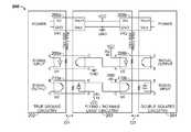
- FIG. 2illustrates an electrical circuit having a ground circuit, a floating circuit, and a double isolated circuit.
- FIG. 3is a schematic drawing of one embodiment of a printed circuit board layout including the circuits described above in FIG. 2 .
- FIG. 4illustrates a 3D view of the printed circuit board of FIG. 3 .
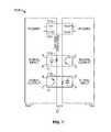
- FIG. 5illustrates one embodiment which can provide an isolation creepage distance of n times a single isolation distance (e.g. n times 7 mm of creepage distance for conventional opto-isolators).
- the present disclosuredescribes and illustrates effective and inexpensive methods and systems for obtaining a wide range of creepage isolation distances. These methods and systems are particularly well suited for high-voltage medical device applications where large creepage isolation distances are required by law or statute.
- FIG. 2illustrates a schematic electrical diagram of one embodiment of an electrical circuit 200 configured to provide large (e.g., up to 14 mm) creepage isolation distances.
- the electrical circuitcan be disposed on, for example, a printed circuit board.
- circuit 200can include ground circuit 202 , floating circuit 203 , and double isolated circuit 204 . Power can be transmitted from the ground circuit 202 to the double isolated circuit 204 via a pair of isolated DC to DC converters 206 a and 206 b .
- the input/output signalscan be transmitted from the ground circuit 202 to the double isolated circuit 204 via opto-isolators 208 a and 208 b (signal input) and opto-isolators 210 a and 210 b (signal output).
- Ground circuit 202can be in optical/electrical communication with floating circuit 203
- floating circuit 203can be in optical/electrical communication with double isolated circuit 204 .
- the opto-isolators used for coupling the circuitscan be electronic devices configured to transfer electrical signals via light waves (e.g., from a light-emitting diode (LED) to a photosensor (such as a phototransistor or photoresistor).
- Opto-isolatorstypically have an LED as an input and various components at the output (e.g., mosfet, IGBT, logic gate, triac, Darlington, etc).
- opto-isolator 208 acan comprise a diode in ground circuit 202 optically coupled to a transistor in floating circuit 203 for communicating signal inputs from the ground circuit to the floating circuit.
- opto-isolator 210 acan comprise a diode in floating circuit 203 optically coupled to a transistor in ground circuit 202 for communicating signal outputs from the floating circuit to the ground circuit.
- a similar configurationcan communicate signal inputs and outputs from the floating circuit to the double isolated circuit, namely, opto-isolator 208 b comprising a diode in the floating circuit optically coupled to a transistor in the double isolated circuit, and opto-isolator 210 b comprising a diode in the double isolated circuit optically coupled to a transistor in the floating circuit.
- the electrical circuit of FIG. 2comprises a ground circuit 202 , a floating circuit 203 optically coupled to the ground circuit via opto-isolators 208 a and 210 a , the floating circuit being electrically isolated from the ground circuit by a first creepage isolation distance D 1 , and an isolated circuit optically coupled to the floating circuit via opto-isolators 208 b and 210 b , the isolated circuit being electrically isolated from the floating circuit by a second creepage isolation distance, the isolated circuit being electrically isolated from the ground circuit by a total creepage isolation distance equal to a combination of the first and second creepage isolation distances.
- the electrical circuit 200 of FIG. 2can be configured to optically couple a signal input from the ground circuit to the floating circuit, and to optically couple the signal input from the floating circuit to the isolated circuit.
- the electrical circuit of FIG. 2can be configured to optically couple a signal input from the isolated circuit to the floating circuit, and to optically couple the signal input from the floating circuit to the ground circuit.
- the floating circuitis isolated from the ground and isolated circuits because there is no physical point of contact between the floating circuit and either the ground or isolated circuits. Instead, the floating circuit is optically coupled to both the ground and isolated circuits.
- the values of the resistors in the floating circuitare calculated using ohms law and depend on the LED forward current, LED voltage drop, and VCC voltage. In some embodiments, very fast opto-isolators with logic output can be used to keep delays less than 10 ns.
- the addition of floating circuit 203 between ground circuit 202 and double isolated circuit 204allows system 200 to essentially double the creepage isolation distances obtainable with a single conventional opto-isolator.
- the creepage isolation distanceeffectively becomes D 1 +D 2 , or 2 ⁇ D.
- conventional opto-isolatorsare capable of approximately ⁇ 7 mm of creepage isolation
- the system of FIG. 2is capable of providing up to approximately ⁇ 14 mm of creepage isolation. It should be understood that if opto-isolators are capable of providing more than the ⁇ 7 mm of creepage isolation, the circuit systems described herein would still be capable of providing double the creepage isolation distances obtainable with a single opto-isolator.
- FIG. 3is a schematic drawing of one embodiment of a printed circuit board layout including the circuits described above in FIG. 2 .
- printed circuit board 301can include ground circuit 302 , floating circuit 303 , and double isolated circuit 304 .
- Ground circuit 302can be electrically isolated from floating circuit 303 via opto-isolator 308 .
- double isolated circuit 304can be electrically isolated from floating circuit 303 via opto-isolator 310 .
- this embodimentprovides a creepage isolation distance of 7.24 mm+7.43 mm for a total of approximately 14.73 mm of isolation.
- FIG. 4illustrates a 3D view of the printed circuit board of FIG. 3 .
- Printed circuit board 401includes all of the same features of the PCB layout of FIG. 3 , including ground circuit 402 , floating circuit 403 , and double isolated circuit 404 , and opto-isolators 408 and 410 .
- PCB 401also illustrates the input/output signal path from ground circuit 402 , through floating circuit 403 , to double isolated circuit 404 and back.
- it is important that the creepage requirementsare met throughout the entire PCB.
- the circuits shown in FIGS. 3 and 4satisfy the requirement of having a minimum of ⁇ 14 mm of creepage distance throughout the entire PCB.
- FIG. 5illustrates one embodiment which can provide an isolation creepage distance of n times a single isolation distance (e.g. n times 7 mm of creepage distance for conventional opto-isolators).
- multiple floating circuitsare disposed between the ground circuit 502 and the isolated circuit 504 .
- the amount of creepage distance desireddetermines the number of floating circuits used. For example, to achieve approximately 21 mm of creepage distance with a conventional opto-insulator, a total of two floating circuits can be used between the ground and isolated circuits.
- the input/output signalscan be optically transmitted from the ground circuit, through the floating circuits, to the isolated circuit, via opto-insulators 508 a / 510 a through 508 n +1/ 510 n+ 1.
- n+1 DC/DC converterscan transfer power from the ground circuit, through the floating circuits, to the isolated circuit.
- This configurationprovides for a total isolation creepage distance of n times the amount of isolation provided by a single opto-insulator. For example, assuming an opto-isolator capable of providing 7 mm of isolation, two floating circuits would provide ⁇ 21 mm of isolation, three floating circuits would provide ⁇ 28 mm of isolation, and so forth.
- the electrical circuit of FIG. 5comprises a ground circuit 502 , a first floating circuit 203 a optically coupled to the ground circuit via opto-isolators 508 a and 510 a , the floating circuit being electrically isolated from the ground circuit by a first creepage isolation distance D 1 , a second floating circuit 203 n +1 optically coupled to the first floating circuit via opto-isolators 508 b and 510 b , the second floating circuit being electrically isolated from the ground circuit by a first creepage isolation distance D 1 and a second creepage isolation distance D 2 , the electrical circuit further comprising an isolated circuit optically coupled to the second floating circuit via opto-isolators 508 n +1 and 510 n+ 1, the isolated circuit being electrically isolated from the floating circuit by a third creepage isolation distance, the isolated circuit being electrically isolated from
- the circuitcan be configured to optically couple a signal input from the ground circuit to the first floating circuit, to optically couple the signal input from the first floating circuit to the second floating circuit, and to optically couple the signal input from the second floating circuit to the isolated circuit.
- the electrical circuit of FIG. 5can be configured to optically couple a signal input from the isolated circuit to the second floating circuit, to optically couple the signal input from the second floating circuit to the first floating circuit, and to optically couple the signal input from the first floating circuit to the ground circuit
Landscapes
- Engineering & Computer Science (AREA)
- Microelectronics & Electronic Packaging (AREA)
- Amplifiers (AREA)
- Photo Coupler, Interrupter, Optical-To-Optical Conversion Devices (AREA)
- Structure Of Printed Boards (AREA)
- Combinations Of Printed Boards (AREA)
Abstract
Description
All publications and patent applications mentioned in this specification are herein incorporated by reference to the same extent as if each individual publication or patent application was specifically and individually indicated to be incorporated by reference.
The present disclosure relates generally to powering medical devices. More specifically, the present disclosure relates to obtaining sufficient creepage insulation distances required for high voltage medical devices.
Medical devices having electrical components typically must meet various electrical safety standards imposed by governing bodies (for example, in the United States, medical electrical equipment must satisfy the general standard IEC 60601-1 published by the International Electrotechnical Commission). One of the major concerns in electrical devices is electrical isolation. In applications where high voltages are used in close proximity to a patient, it can be very challenging to achieve the proper level of electrical isolation, since as the voltage used increases, the creepage distance and air clearance required must also be increased.
Generally, opto-isolators are used to transfer a signal over an isolation barrier, and DC to DC converters or transformers are used to transfer power over the isolation barriers. Opto-isolators currently on the market are capable of obtaining creepage insulation up to approximately 7 mm. However, in very high voltage devices, these opto-isolators are not capable of achieving the creepage insulation required by IEC 60601-1.
Thus, methods and systems are required for high voltage medical devices to obtain creepage isolation of at least 12 mm-14 mm.
In one embodiment, an electrical circuit is provided, comprising a ground circuit, a floating circuit optically coupled to the ground circuit, the floating circuit being electrically isolated from the ground circuit by a first creepage isolation distance, and an isolated circuit optically coupled to the floating circuit, the isolated circuit being electrically isolated from the floating circuit by a second creepage isolation distance, the isolated circuit being electrically isolated from the ground circuit by a total creepage isolation distance equal to a combination of the first and second creepage isolation distances.
In some embodiments, the total creepage isolation distance is at least twice as large as the first creepage isolation distance.
In other embodiments, the circuit further comprises a first opto-isolator configured to optically couple a signal input from the ground circuit to the floating circuit. In another embodiment, the circuit further comprises a second opto-isolator configured to optically couple the signal input from the floating circuit to the isolated circuit.
In one embodiment, the first opto-isolator comprises a diode disposed on the ground circuit and a transistor disposed on the floating circuit. In another embodiment, the second opto-isolator comprises a diode disposed on the floating circuit and a transistor disposed on the isolated circuit.
In some embodiments, the circuit further comprises a first opto-isolator configured to optically couple a signal input from the isolated circuit to the floating circuit. In one embodiment, the circuit further comprises a second opto-isolator configured to optically couple the signal input from the floating circuit to the ground circuit.
In one embodiment, the first opto-isolator comprises a diode disposed on the isolated circuit and a transistor disposed on the floating circuit. In another embodiment, the second opto-isolator comprises a diode disposed on the floating circuit and a transistor disposed on the ground circuit.
In some embodiments, the first creepage isolation distance is approximately 7 mm. In another embodiment, the second creepage isolation distance is approximately 7 mm and the total creepage isolation distance is approximately 14 mm.
In one embodiment, the ground circuit, floating circuit, and double isolated circuit are disposed on a printed circuit board.
An electrical circuit is provided, comprising, a ground circuit, a first floating circuit optically coupled to the ground circuit, the first floating circuit being electrically isolated from the ground circuit by a first creepage isolation distance, a second floating circuit optically coupled to the first floating circuit, the second floating circuit being electrically isolated from the first floating circuit by a second creepage isolation distance, and a triple isolated circuit optically coupled to the second floating circuit, the triple isolated circuit being electrically isolated from the second floating ground circuit by third creepage isolation distance, the triple isolated circuit being isolated from the ground circuit by a total creepage isolation distance equal to a combination of the first, second, and third creepage isolation distance,
In some embodiments, the total creepage isolation distance is at least three times as large as the first creepage isolation distance.
In one embodiment, the circuit further comprises a first opto-isolator configured to optically couple a signal input from the ground circuit to the first floating circuit. In another embodiment, the circuit further comprises a second opto-isolator configured to optically couple the signal input from the first floating circuit to the second floating circuit. In an additional embodiment, the circuit further comprises a third opto-isolator configured to optically couple the signal input from the second floating circuit to the triple isolated circuit.
In some embodiments, the first opto-isolator comprises a diode disposed on the ground circuit and a transistor disposed on the first floating circuit. In another embodiment, the second opto-isolator comprises a diode disposed on the first floating circuit and a transistor disposed on the second floating circuit. In an additional embodiment, the third opto-isolator comprises a diode disposed on the second floating circuit and a transistor disposed on the triple isolated circuit.
A method of increasing a creepage isolation distance in an electrical circuit is also provided, comprising optically coupling a ground circuit to a floating circuit to electrically isolate the floating circuit from the ground circuit by a first creepage isolation distance, and optically coupling an isolated circuit to the floating circuit to electrically isolate the isolated circuit from the floating circuit by a second creepage isolation distance, and to electrically isolate the isolated circuit from the ground circuit by a total creepage isolation distance equal to a combination of the first and second creepage isolation distances.
In some embodiments of the method, optically coupling comprises optically coupling with an opto-isolator. In another embodiment, the total creepage isolation distance is approximately 14 mm.
The novel features of the invention are set forth with particularity in the claims that follow. A better understanding of the features and advantages of the present invention will be obtained by reference to the following detailed description that sets forth illustrative embodiments, in which the principles of the invention are utilized, and the accompanying drawings of which:
The present disclosure describes and illustrates effective and inexpensive methods and systems for obtaining a wide range of creepage isolation distances. These methods and systems are particularly well suited for high-voltage medical device applications where large creepage isolation distances are required by law or statute.
As shown inFIG. 2 , opto-isolator 208acan comprise a diode inground circuit 202 optically coupled to a transistor infloating circuit 203 for communicating signal inputs from the ground circuit to the floating circuit. Similarly, opto-isolator 210acan comprise a diode infloating circuit 203 optically coupled to a transistor inground circuit 202 for communicating signal outputs from the floating circuit to the ground circuit. A similar configuration can communicate signal inputs and outputs from the floating circuit to the double isolated circuit, namely, opto-isolator 208bcomprising a diode in the floating circuit optically coupled to a transistor in the double isolated circuit, and opto-isolator 210bcomprising a diode in the double isolated circuit optically coupled to a transistor in the floating circuit.
In one embodiment, the electrical circuit ofFIG. 2 comprises aground circuit 202, afloating circuit 203 optically coupled to the ground circuit via opto-isolators isolators
Theelectrical circuit 200 ofFIG. 2 can be configured to optically couple a signal input from the ground circuit to the floating circuit, and to optically couple the signal input from the floating circuit to the isolated circuit. Similarly, the electrical circuit ofFIG. 2 can be configured to optically couple a signal input from the isolated circuit to the floating circuit, and to optically couple the signal input from the floating circuit to the ground circuit.
The floating circuit is isolated from the ground and isolated circuits because there is no physical point of contact between the floating circuit and either the ground or isolated circuits. Instead, the floating circuit is optically coupled to both the ground and isolated circuits. The values of the resistors in the floating circuit are calculated using ohms law and depend on the LED forward current, LED voltage drop, and VCC voltage. In some embodiments, very fast opto-isolators with logic output can be used to keep delays less than 10 ns.
InFIG. 2 , the addition of floatingcircuit 203 betweenground circuit 202 and doubleisolated circuit 204 allowssystem 200 to essentially double the creepage isolation distances obtainable with a single conventional opto-isolator. InFIG. 2 , the creepage isolation distance effectively becomes D1+D2, or 2×D. Since conventional opto-isolators are capable of approximately ˜7 mm of creepage isolation, the system ofFIG. 2 is capable of providing up to approximately ˜14 mm of creepage isolation. It should be understood that if opto-isolators are capable of providing more than the ˜7 mm of creepage isolation, the circuit systems described herein would still be capable of providing double the creepage isolation distances obtainable with a single opto-isolator.
The embodiments described above can be further applied to providing even larger isolation creepage distances by using multiple floating circuits.FIG. 5 illustrates one embodiment which can provide an isolation creepage distance of n times a single isolation distance (e.g. n times 7 mm of creepage distance for conventional opto-isolators). InFIG. 5 , multiple floating circuits are disposed between theground circuit 502 and theisolated circuit 504. The amount of creepage distance desired determines the number of floating circuits used. For example, to achieve approximately 21 mm of creepage distance with a conventional opto-insulator, a total of two floating circuits can be used between the ground and isolated circuits. The input/output signals can be optically transmitted from the ground circuit, through the floating circuits, to the isolated circuit, via opto-insulators 508a/510athrough508n+1/510n+1. Similarly, n+1 DC/DC converters can transfer power from the ground circuit, through the floating circuits, to the isolated circuit. This configuration provides for a total isolation creepage distance of n times the amount of isolation provided by a single opto-insulator. For example, assuming an opto-isolator capable of providing 7 mm of isolation, two floating circuits would provide ˜21 mm of isolation, three floating circuits would provide ˜28 mm of isolation, and so forth.
Referring toFIG. 5 , an electrical circuit with two floating circuits (and a total of ˜21 mm of isolation with conventional opto-isolators) can be described. In this embodiment, the electrical circuit ofFIG. 5 comprises aground circuit 502, a first floatingcircuit 203aoptically coupled to the ground circuit via opto-isolators circuit 203n+1 optically coupled to the first floating circuit via opto-isolators isolators 508n+1 and510n+1, the isolated circuit being electrically isolated from the floating circuit by a third creepage isolation distance, the isolated circuit being electrically isolated from the ground circuit by a total creepage isolation distance equal to a combination of the first, second, and third creepage isolation distances.
In this example, the circuit can be configured to optically couple a signal input from the ground circuit to the first floating circuit, to optically couple the signal input from the first floating circuit to the second floating circuit, and to optically couple the signal input from the second floating circuit to the isolated circuit. Similarly, the electrical circuit ofFIG. 5 can be configured to optically couple a signal input from the isolated circuit to the second floating circuit, to optically couple the signal input from the second floating circuit to the first floating circuit, and to optically couple the signal input from the first floating circuit to the ground circuit
As for additional details pertinent to the present invention, materials and manufacturing techniques may be employed as within the level of those with skill in the relevant art. The same may hold true with respect to method-based aspects of the invention in terms of additional acts commonly or logically employed. Also, it is contemplated that any optional feature of the inventive variations described may be set forth and claimed independently, or in combination with any one or more of the features described herein. Likewise, reference to a singular item, includes the possibility that there are plural of the same items present. More specifically, as used herein and in the appended claims, the singular forms “a,” “and,” “said,” and “the” include plural referents unless the context clearly dictates otherwise. It is further noted that the claims may be drafted to exclude any optional element. As such, this statement is intended to serve as antecedent basis for use of such exclusive terminology as “solely,” “only” and the like in connection with the recitation of claim elements, or use of a “negative” limitation. Unless defined otherwise herein, all technical and scientific terms used herein have the same meaning as commonly understood by one of ordinary skill in the art to which this invention belongs. The breadth of the present invention is not to be limited by the subject specification, but rather only by the plain meaning of the claim terms employed.
Claims (24)
1. An electrical circuit, comprising:
a ground circuit;
a floating circuit optically coupled to the ground circuit with a first opto-isolator, the floating circuit being electrically isolated from the ground circuit by a first creepage isolation distance; and
an isolated circuit optically coupled to the floating circuit with a second opto-isolator, the isolated circuit being electrically isolated from the floating circuit by a second creepage isolation distance, the first opto-isolator being electrically connected to the second opto-isolator in series so that the isolated circuit is electrically isolated from the ground circuit by a total creepage isolation distance equal to a combination of the first and second creepage isolation distances.
2. The electrical circuit ofclaim 1 wherein the total creepage isolation distance is at least twice as large as the first creepage isolation distance.
3. The electrical circuit ofclaim 1 wherein the first opto-isolator is configured to optically couple a signal input from the ground circuit to the floating circuit.
4. The electrical circuit ofclaim 3 wherein the second opto-isolator is configured to optically couple the signal input from the floating circuit to the isolated circuit.
5. The electrical circuit ofclaim 3 wherein the first opto-isolator comprises a diode disposed on the ground circuit and a transistor disposed on the floating circuit.
6. The electrical circuit ofclaim 4 wherein the second opto-isolator comprises a diode disposed on the floating circuit and a transistor disposed on the isolated circuit.
7. The electrical circuit ofclaim 1 wherein the first opto-isolator is configured to optically couple a signal input from the isolated circuit to the floating circuit.
8. The electrical circuit ofclaim 7 wherein the second opto-isolator is configured to optically couple the signal input from the floating circuit to the ground circuit.
9. The electrical circuit ofclaim 7 wherein the first opto-isolator comprises a diode disposed on the isolated circuit and a transistor disposed on the floating circuit.
10. The electrical circuit ofclaim 8 wherein the second opto-isolator comprises a diode disposed on the floating circuit and a transistor disposed on the ground circuit.
11. The electrical circuit ofclaim 1 wherein the first creepage isolation distance is approximately 7 mm.
12. The electrical circuit ofclaim 1 wherein the second creepage isolation distance is approximately 7 mm and the total creepage isolation distance is approximately 14 mm.
13. The electrical circuit ofclaim 1 wherein the ground circuit, floating circuit, and double isolated circuit are disposed on a printed circuit board.
14. An electrical circuit, comprising:
a ground circuit;
a first floating circuit optically coupled to the ground circuit, the first floating circuit being electrically isolated from the ground circuit by a first creepage isolation distance;
a second floating circuit optically coupled to the first floating circuit, the second floating circuit being electrically isolated from the first floating circuit by a second creepage isolation distance; and
a triple isolated circuit optically coupled to the second floating circuit, the triple isolated circuit being electrically isolated from the second floating ground circuit by a third creepage isolation distance, the triple isolated circuit being isolated from the ground circuit by a total creepage isolation distance equal to a combination of the first, second, and third creepage isolation distances.
15. The electrical circuit ofclaim 14 wherein the total creepage isolation distance is at least three times as large as the first creepage isolation distance.
16. The electrical circuit ofclaim 14 further comprising a first opto-isolator configured to optically couple a signal input from the ground circuit to the first floating circuit.
17. The electrical circuit ofclaim 16 further comprising a second opto-isolator configured to optically couple the signal input from the first floating circuit to the second floating circuit.
18. The electrical circuit ofclaim 17 further comprising a third opto-isolator configured to optically couple the signal input from the second floating circuit to the triple isolated circuit.
19. The electrical circuit ofclaim 16 wherein the first opto-isolator comprises a diode disposed on the ground circuit and a transistor disposed on the first floating circuit.
20. The electrical circuit ofclaim 17 wherein the second opto-isolator comprises a diode disposed on the first floating circuit and a transistor disposed on the second floating circuit.
21. The electrical circuit ofclaim 18 wherein the third opto-isolator comprises a diode disposed on the second floating circuit and a transistor disposed on the triple isolated circuit.
22. A method of increasing a creepage isolation distance in an electrical circuit, comprising:
optically coupling a ground circuit to a floating circuit with a first opto-isolator to electrically isolate the floating circuit from the ground circuit by a first creepage isolation distance; and
optically coupling an isolated circuit to the floating circuit with a second-opto isolator to electrically isolate the isolated circuit from the floating circuit by a second creepage isolation distance, and electrically connecting the first opto-isolator to the second opto-isolator in series to electrically isolate the isolated circuit from the ground circuit by a total creepage isolation distance equal to a combination of the first and second creepage isolation distances.
23. The method ofclaim 22 wherein the total creepage isolation distance is approximately 14 mm.
24. An electrical circuit, comprising:
a ground circuit;
a floating circuit optically coupled to the ground circuit, the floating circuit being electrically isolated from the ground circuit by a first creepage isolation distance; and
an isolated circuit comprising a first opto-isolator configured to optically couple a signal input of the isolated circuit to the floating circuit, the first opto-isolator comprising a diode disposed on the isolated circuit and a transistor disposed on the floating circuit, the isolated circuit being electrically isolated from the floating circuit by a second creepage isolation distance, the isolated circuit being electrically isolated from the ground circuit by a total creepage isolation distance equal to a combination of the first and second creepage isolation distances.
Priority Applications (7)
| Application Number | Priority Date | Filing Date | Title |
|---|---|---|---|
| US13/446,783US9049783B2 (en) | 2012-04-13 | 2012-04-13 | Systems and methods for obtaining large creepage isolation on printed circuit boards |
| AU2013245840AAU2013245840B2 (en) | 2012-04-13 | 2013-04-11 | Systems and methods for obtaining large creepage isolation on printed circuit boards |
| CA2869400ACA2869400C (en) | 2012-04-13 | 2013-04-11 | Systems and methods for obtaining large creepage isolation on printed circuit boards |
| EP13775051.9AEP2836871A4 (en) | 2012-04-13 | 2013-04-11 | Systems and methods for obtaining large creepage isolation on printed circuit boards |
| PCT/US2013/036138WO2013155279A1 (en) | 2012-04-13 | 2013-04-11 | Systems and methods for obtaining large creepage isolation on printed circuit boards |
| HK15107998.0AHK1207425A1 (en) | 2012-04-13 | 2013-04-11 | Systems and methods for obtaining large creepage isolation on printed circuit boards |
| JP2015505898AJP2015524995A (en) | 2012-04-13 | 2013-04-11 | System and method for obtaining large creepage insulation on a printed circuit board |
Applications Claiming Priority (1)
| Application Number | Priority Date | Filing Date | Title |
|---|---|---|---|
| US13/446,783US9049783B2 (en) | 2012-04-13 | 2012-04-13 | Systems and methods for obtaining large creepage isolation on printed circuit boards |
Publications (2)
| Publication Number | Publication Date |
|---|---|
| US20130269982A1 US20130269982A1 (en) | 2013-10-17 |
| US9049783B2true US9049783B2 (en) | 2015-06-02 |
Family
ID=49324061
Family Applications (1)
| Application Number | Title | Priority Date | Filing Date |
|---|---|---|---|
| US13/446,783Active2033-03-03US9049783B2 (en) | 2012-04-13 | 2012-04-13 | Systems and methods for obtaining large creepage isolation on printed circuit boards |
Country Status (7)
| Country | Link |
|---|---|
| US (1) | US9049783B2 (en) |
| EP (1) | EP2836871A4 (en) |
| JP (1) | JP2015524995A (en) |
| AU (1) | AU2013245840B2 (en) |
| CA (1) | CA2869400C (en) |
| HK (1) | HK1207425A1 (en) |
| WO (1) | WO2013155279A1 (en) |
Cited By (13)
| Publication number | Priority date | Publication date | Assignee | Title |
|---|---|---|---|---|
| US9526923B2 (en) | 2009-08-17 | 2016-12-27 | Histosonics, Inc. | Disposable acoustic coupling medium container |
| US10071266B2 (en) | 2011-08-10 | 2018-09-11 | The Regents Of The University Of Michigan | Lesion generation through bone using histotripsy therapy without aberration correction |
| US10219815B2 (en) | 2005-09-22 | 2019-03-05 | The Regents Of The University Of Michigan | Histotripsy for thrombolysis |
| US10416122B2 (en)* | 2017-10-31 | 2019-09-17 | Westinghouse Electric Company Llc | Ultrasonic phased array transducer apparatus for the nondestructive inspection of a component under test |
| US10780298B2 (en) | 2013-08-22 | 2020-09-22 | The Regents Of The University Of Michigan | Histotripsy using very short monopolar ultrasound pulses |
| US11058399B2 (en) | 2012-10-05 | 2021-07-13 | The Regents Of The University Of Michigan | Bubble-induced color doppler feedback during histotripsy |
| US11135454B2 (en) | 2015-06-24 | 2021-10-05 | The Regents Of The University Of Michigan | Histotripsy therapy systems and methods for the treatment of brain tissue |
| US11432900B2 (en) | 2013-07-03 | 2022-09-06 | Histosonics, Inc. | Articulating arm limiter for cavitational ultrasound therapy system |
| US11497465B2 (en) | 2019-10-25 | 2022-11-15 | Bard Peripheral Vascular, Inc. | Method for treatment of a vascular lesion |
| US11648424B2 (en) | 2018-11-28 | 2023-05-16 | Histosonics Inc. | Histotripsy systems and methods |
| US11813485B2 (en) | 2020-01-28 | 2023-11-14 | The Regents Of The University Of Michigan | Systems and methods for histotripsy immunosensitization |
| US12318636B2 (en) | 2022-10-28 | 2025-06-03 | Histosonics, Inc. | Histotripsy systems and methods |
| US12343568B2 (en) | 2020-08-27 | 2025-07-01 | The Regents Of The University Of Michigan | Ultrasound transducer with transmit-receive capability for histotripsy |
Families Citing this family (5)
| Publication number | Priority date | Publication date | Assignee | Title |
|---|---|---|---|---|
| EP3016594B1 (en) | 2013-07-03 | 2023-01-25 | Histosonics, Inc. | Histotripsy excitation sequences optimized for bubble cloud formation using shock scattering |
| JP6272745B2 (en)* | 2014-10-27 | 2018-01-31 | ソニー・オリンパスメディカルソリューションズ株式会社 | Medical device substrate and medical device |
| DE102015221688A1 (en)* | 2015-11-05 | 2017-05-11 | Osram Gmbh | Method for reducing conductor spacing in electronic printed circuit boards and electronic printed circuit board with reduced distances between printed conductors |
| CN105811943A (en)* | 2016-04-06 | 2016-07-27 | 华中科技大学 | Integrated driving device applied to series compression type IGBT |
| US12022607B2 (en)* | 2022-02-11 | 2024-06-25 | Hamilton Sundstrand Corporation | Noise control for printed circuit board |
Citations (273)
| Publication number | Priority date | Publication date | Assignee | Title |
|---|---|---|---|---|
| US3243497A (en) | 1964-12-11 | 1966-03-29 | Dynapower Systems Corp Of Cali | Universal support for electrotherapeutic treatment head |
| US3679021A (en) | 1970-03-25 | 1972-07-25 | Eg & G Inc | Acoustic pulse generating system |
| US4024501A (en) | 1975-09-03 | 1977-05-17 | Standard Oil Company | Line driver system |
| US4051394A (en)* | 1976-03-15 | 1977-09-27 | The Boeing Company | Zero crossing ac relay control circuit |
| US4117446A (en) | 1974-11-28 | 1978-09-26 | Agence Nationale De Valorisation De La Recherche (A N V A R) | Devices for probing by ultrasonic radiation |
| EP0017382A1 (en) | 1979-03-20 | 1980-10-15 | THE GENERAL ELECTRIC COMPANY, p.l.c. | Ultrasonic imaging system |
| US4269174A (en) | 1979-08-06 | 1981-05-26 | Medical Dynamics, Inc. | Transcutaneous vasectomy apparatus and method |
| US4277367A (en) | 1978-10-23 | 1981-07-07 | Wisconsin Alumni Research Foundation | Phantom material and method |
| US4351038A (en) | 1979-12-31 | 1982-09-21 | Agence Nationale De Valorisation De La Recherche (Anvar) | Ultrasonic examination and imaging |
| GB2099582A (en) | 1980-02-08 | 1982-12-08 | Stanford Res Inst Int | Ultrasonic image methods and apparatus |
| US4406153A (en) | 1979-05-04 | 1983-09-27 | Acoustic Standards Corporation | Ultrasonic beam characterization device |
| DE3220751A1 (en) | 1982-06-02 | 1983-12-08 | Jörg Dr. 8022 Grünwald Schüller | Device for crushing concrements, especially renal calculi, in living human or animal bodies |
| US4440025A (en) | 1980-06-27 | 1984-04-03 | Matsushita Electric Industrial Company, Limited | Arc scan transducer array having a diverging lens |
| US4453408A (en) | 1981-03-09 | 1984-06-12 | William Clayman | Device for testing ultrasonic beam profiles |
| US4483345A (en) | 1981-08-08 | 1984-11-20 | Fujitsu Limited | Pressure measuring system with ultrasonic wave |
| JPS6080779A (en) | 1983-10-07 | 1985-05-08 | Matsushita Electric Ind Co Ltd | Magnetic field sensor |
| US4549533A (en) | 1984-01-30 | 1985-10-29 | University Of Illinois | Apparatus and method for generating and directing ultrasound |
| US4550606A (en) | 1982-09-28 | 1985-11-05 | Cornell Research Foundation, Inc. | Ultrasonic transducer array with controlled excitation pattern |
| US4575330A (en) | 1984-08-08 | 1986-03-11 | Uvp, Inc. | Apparatus for production of three-dimensional objects by stereolithography |
| JPS61196718A (en) | 1985-02-22 | 1986-08-30 | 株式会社日立製作所 | Earth fault protection device |
| US4622972A (en) | 1981-10-05 | 1986-11-18 | Varian Associates, Inc. | Ultrasound hyperthermia applicator with variable coherence by multi-spiral focusing |
| US4625731A (en) | 1984-10-10 | 1986-12-02 | Picker International, Inc. | Ultrasonic image display mounting |
| US4641378A (en) | 1984-06-06 | 1987-02-03 | Raycom Systems, Inc. | Fiber optic communication module |
| US4669483A (en) | 1984-07-21 | 1987-06-02 | Dornier System Gmbh | Lithotripsy system having locating and orienting apparatus |
| DE3544628A1 (en) | 1985-12-17 | 1987-06-19 | Eisenmenger Wolfgang | DEVICE FOR MECHANICALLY ACOUSTIC CONNECTION OF PRESSURE SHAFTS, ESPECIALLY OF FOCUSED SHOCK WAVES TO THE BODY OF LIVING BEINGS |
| US4689986A (en) | 1985-03-13 | 1987-09-01 | The University Of Michigan | Variable frequency gas-bubble-manipulating apparatus and method |
| US4757820A (en) | 1985-03-15 | 1988-07-19 | Kabushiki Kaisha Toshiba | Ultrasound therapy system |
| US4791915A (en) | 1986-09-29 | 1988-12-20 | Dynawave Corporation | Ultrasound therapy device |
| US4819621A (en) | 1986-03-11 | 1989-04-11 | Richard Wolf Gmbh | Method for detection of cavitations during medical application of high sonic energy |
| US4829491A (en) | 1984-07-12 | 1989-05-09 | Siemens Aktiengesellschaft | Phased-array equipment |
| EP0320303A2 (en) | 1987-12-11 | 1989-06-14 | General Electric Company | Coherent beam formation |
| US4856107A (en) | 1987-04-28 | 1989-08-08 | Edap International | Acoustic filter for suppressing or attenuating the negative half-waves of an elastic wave and an elastic wave generator comprising such a filter |
| US4865042A (en) | 1985-08-16 | 1989-09-12 | Hitachi, Ltd. | Ultrasonic irradiation system |
| EP0332871A2 (en) | 1988-03-16 | 1989-09-20 | Dornier Medizintechnik Gmbh | Destruction of concretions by combined treatment |
| DE3817094A1 (en) | 1988-04-18 | 1989-11-30 | Schubert Werner | Coupling and adhesive device for shock wave treatment units |
| US4888746A (en) | 1987-09-24 | 1989-12-19 | Richard Wolf Gmbh | Focussing ultrasound transducer |
| US4890267A (en) | 1985-09-24 | 1989-12-26 | Hewlett-Packard Company | Switch matrix |
| US4922917A (en) | 1987-08-14 | 1990-05-08 | Edap International | Ultrasonic tissue characterization |
| US4938217A (en) | 1988-06-21 | 1990-07-03 | Massachusetts Institute Of Technology | Electronically-controlled variable focus ultrasound hyperthermia system |
| EP0384831A2 (en) | 1989-02-21 | 1990-08-29 | Technomed International | Apparatus for selective destruction of cells including soft tissues and bones inside a living being by implosing of gas bubbles |
| US4957099A (en) | 1988-02-10 | 1990-09-18 | Siemens Aktiengesellschaft | Shock wave source for extracorporeal lithotripsy |
| US4973980A (en) | 1987-09-11 | 1990-11-27 | Dataproducts Corporation | Acoustic microstreaming in an ink jet apparatus |
| US4984575A (en) | 1987-04-16 | 1991-01-15 | Olympus Optical Co., Ltd. | Therapeutical apparatus of extracorporeal type |
| US4991151A (en) | 1987-04-28 | 1991-02-05 | Edap International | Elastic pulse generator having a desired predetermined wave form |
| US5014686A (en) | 1989-08-31 | 1991-05-14 | International Sonic Technologies | Phantom kidney stone system |
| USRE33590E (en) | 1983-12-14 | 1991-05-21 | Edap International, S.A. | Method for examining, localizing and treating with ultrasound |
| US5065751A (en) | 1990-01-03 | 1991-11-19 | Wolf Gerald L | Method and apparatus for reversibly occluding a biological tube |
| US5080102A (en) | 1983-12-14 | 1992-01-14 | Edap International, S.A. | Examining, localizing and treatment with ultrasound |
| US5091893A (en) | 1990-04-05 | 1992-02-25 | General Electric Company | Ultrasonic array with a high density of electrical connections |
| US5092336A (en) | 1989-02-08 | 1992-03-03 | Universite Paris Vii-Bureau De La Valorisation Et De Relations Industrielle | Method and device for localization and focusing of acoustic waves in tissues |
| US5097709A (en) | 1989-02-16 | 1992-03-24 | Hitachi, Ltd. | Ultrasonic imaging system |
| US5143074A (en) | 1983-12-14 | 1992-09-01 | Edap International | Ultrasonic treatment device using a focussing and oscillating piezoelectric element |
| US5150711A (en) | 1983-12-14 | 1992-09-29 | Edap International, S.A. | Ultra-high-speed extracorporeal ultrasound hyperthermia treatment device |
| US5158070A (en) | 1983-12-14 | 1992-10-27 | Edap International, S.A. | Method for the localized destruction of soft structures using negative pressure elastic waves |
| US5158071A (en) | 1988-07-01 | 1992-10-27 | Hitachi, Ltd. | Ultrasonic apparatus for therapeutical use |
| US5163421A (en) | 1988-01-22 | 1992-11-17 | Angiosonics, Inc. | In vivo ultrasonic system with angioplasty and ultrasonic contrast imaging |
| US5209221A (en) | 1988-03-01 | 1993-05-11 | Richard Wolf Gmbh | Ultrasonic treatment of pathological tissue |
| US5215680A (en) | 1990-07-10 | 1993-06-01 | Cavitation-Control Technology, Inc. | Method for the production of medical-grade lipid-coated microbubbles, paramagnetic labeling of such microbubbles and therapeutic uses of microbubbles |
| US5230340A (en) | 1992-04-13 | 1993-07-27 | General Electric Company | Ultrasound imaging system with improved dynamic focusing |
| US5295484A (en) | 1992-05-19 | 1994-03-22 | Arizona Board Of Regents For And On Behalf Of The University Of Arizona | Apparatus and method for intra-cardiac ablation of arrhythmias |
| WO1994006355A1 (en) | 1992-09-14 | 1994-03-31 | Coraje, Inc. | Apparatus and method for enhanced intravascular phonophoresis including dissolution of intravascular blockage and concomitant inhibition of restenosis |
| US5316000A (en) | 1991-03-05 | 1994-05-31 | Technomed International (Societe Anonyme) | Use of at least one composite piezoelectric transducer in the manufacture of an ultrasonic therapy apparatus for applying therapy, in a body zone, in particular to concretions, to tissue, or to bones, of a living being and method of ultrasonic therapy |
| US5354258A (en) | 1992-01-07 | 1994-10-11 | Edap International | Ultra-high-speed extracorporeal ultrasound hyperthermia treatment method |
| JPH06304178A (en) | 1993-04-02 | 1994-11-01 | Siemens Ag | A therapeutic device for the treatment of pathological tissue by focused ultrasound |
| US5380411A (en) | 1987-12-02 | 1995-01-10 | Schering Aktiengesellschaft | Ultrasound or shock wave work process and preparation for carrying out same |
| US5409002A (en) | 1989-07-12 | 1995-04-25 | Focus Surgery Incorporated | Treatment system with localization |
| US5431621A (en) | 1984-11-26 | 1995-07-11 | Edap International | Process and device of an anatomic anomaly by means of elastic waves, with tracking of the target and automatic triggering of the shootings |
| US5435311A (en) | 1989-06-27 | 1995-07-25 | Hitachi, Ltd. | Ultrasound therapeutic system |
| US5443069A (en) | 1992-11-16 | 1995-08-22 | Siemens Aktiengesellschaft | Therapeutic ultrasound applicator for the urogenital region |
| US5469852A (en) | 1993-03-12 | 1995-11-28 | Kabushiki Kaisha Toshiba | Ultrasound diagnosis apparatus and probe therefor |
| US5501655A (en) | 1992-03-31 | 1996-03-26 | Massachusetts Institute Of Technology | Apparatus and method for acoustic heat generation and hyperthermia |
| JPH0884740A (en) | 1994-09-16 | 1996-04-02 | Toshiba Corp | Treatment equipment |
| JPH08131454A (en) | 1994-09-17 | 1996-05-28 | Toshiba Corp | Ultrasonic treatment device and ultrasonic irradiation device |
| US5520188A (en) | 1994-11-02 | 1996-05-28 | Focus Surgery Inc. | Annular array transducer |
| US5523058A (en) | 1992-09-16 | 1996-06-04 | Hitachi, Ltd. | Ultrasonic irradiation apparatus and processing apparatus based thereon |
| US5524620A (en) | 1991-11-12 | 1996-06-11 | November Technologies Ltd. | Ablation of blood thrombi by means of acoustic energy |
| US5540909A (en) | 1994-09-28 | 1996-07-30 | Alliance Pharmaceutical Corp. | Harmonic ultrasound imaging with microbubbles |
| US5542935A (en) | 1989-12-22 | 1996-08-06 | Imarx Pharmaceutical Corp. | Therapeutic delivery systems related applications |
| US5558092A (en) | 1995-06-06 | 1996-09-24 | Imarx Pharmaceutical Corp. | Methods and apparatus for performing diagnostic and therapeutic ultrasound simultaneously |
| US5563346A (en) | 1994-02-21 | 1996-10-08 | Siemens Aktiengesellschaft | Method and device for imaging an object using a two-dimensional ultrasonic array |
| US5566675A (en) | 1995-06-30 | 1996-10-22 | Siemens Medical Systems, Inc. | Beamformer for phase aberration correction |
| US5573497A (en) | 1994-11-30 | 1996-11-12 | Technomed Medical Systems And Institut National | High-intensity ultrasound therapy method and apparatus with controlled cavitation effect and reduced side lobes |
| US5580575A (en) | 1989-12-22 | 1996-12-03 | Imarx Pharmaceutical Corp. | Therapeutic drug delivery systems |
| US5582578A (en) | 1995-08-01 | 1996-12-10 | Duke University | Method for the comminution of concretions |
| US5590657A (en) | 1995-11-06 | 1997-01-07 | The Regents Of The University Of Michigan | Phased array ultrasound system and method for cardiac ablation |
| EP0755653A1 (en) | 1995-07-27 | 1997-01-29 | Hewlett-Packard GmbH | Patient monitoring module |
| US5601526A (en) | 1991-12-20 | 1997-02-11 | Technomed Medical Systems | Ultrasound therapy apparatus delivering ultrasound waves having thermal and cavitation effects |
| US5617862A (en) | 1995-05-02 | 1997-04-08 | Acuson Corporation | Method and apparatus for beamformer system with variable aperture |
| US5648098A (en) | 1995-10-17 | 1997-07-15 | The Board Of Regents Of The University Of Nebraska | Thrombolytic agents and methods of treatment for thrombosis |
| US5676452A (en) | 1995-03-02 | 1997-10-14 | Gebr. Berchtold Gmbh & Co. | Operating lamp with main bulb and replacement bulb |
| US5676692A (en) | 1996-03-28 | 1997-10-14 | Indianapolis Center For Advanced Research, Inc. | Focussed ultrasound tissue treatment method |
| US5678554A (en) | 1996-07-02 | 1997-10-21 | Acuson Corporation | Ultrasound transducer for multiple focusing and method for manufacture thereof |
| US5694936A (en) | 1994-09-17 | 1997-12-09 | Kabushiki Kaisha Toshiba | Ultrasonic apparatus for thermotherapy with variable frequency for suppressing cavitation |
| US5695460A (en) | 1994-09-09 | 1997-12-09 | Coraje, Inc. | Enhancement of ultrasound thrombolysis |
| US5717657A (en) | 1996-06-24 | 1998-02-10 | The United States Of America As Represented By The Secretary Of The Navy | Acoustical cavitation suppressor for flow fields |
| US5724972A (en) | 1996-05-02 | 1998-03-10 | Acuson Corporation | Method and apparatus for distributed focus control with slope tracking |
| US5753929A (en)* | 1996-08-28 | 1998-05-19 | Motorola, Inc. | Multi-directional optocoupler and method of manufacture |
| US5759162A (en) | 1992-03-10 | 1998-06-02 | Siemens Aktiengesellschaft | Method and apparatus for ultrasound tissue therapy |
| US5766138A (en) | 1996-04-18 | 1998-06-16 | Siemens Aktiengesellschaft | Therapy apparatus with simple setting of a desired distance from a reference point |
| US5769790A (en) | 1996-10-25 | 1998-06-23 | General Electric Company | Focused ultrasound surgery system guided by ultrasound imaging |
| US5797848A (en) | 1997-01-31 | 1998-08-25 | Acuson Corporation | Ultrasonic transducer assembly with improved electrical interface |
| US5823962A (en) | 1996-09-02 | 1998-10-20 | Siemens Aktiengesellschaft | Ultrasound transducer for diagnostic and therapeutic use |
| US5827204A (en) | 1996-11-26 | 1998-10-27 | Grandia; Willem | Medical noninvasive operations using focused modulated high power ultrasound |
| US5836896A (en) | 1996-08-19 | 1998-11-17 | Angiosonics | Method of inhibiting restenosis by applying ultrasonic energy |
| US5849727A (en) | 1996-06-28 | 1998-12-15 | Board Of Regents Of The University Of Nebraska | Compositions and methods for altering the biodistribution of biological agents |
| US5873902A (en) | 1995-03-31 | 1999-02-23 | Focus Surgery, Inc. | Ultrasound intensity determining method and apparatus |
| US5879314A (en) | 1997-06-30 | 1999-03-09 | Cybersonics, Inc. | Transducer assembly and method for coupling ultrasonic energy to a body for thrombolysis of vascular thrombi |
| US5932807A (en) | 1994-10-25 | 1999-08-03 | U.S. Philips Corporation | Device for the non-destructive testing of hollow tubular objects by means of ultrasound |
| US5947904A (en) | 1997-08-21 | 1999-09-07 | Acuson Corporation | Ultrasonic method and system for imaging blood flow including disruption or activation of a contrast agent |
| US6001069A (en) | 1997-05-01 | 1999-12-14 | Ekos Corporation | Ultrasound catheter for providing a therapeutic effect to a vessel of a body |
| US6022309A (en) | 1996-04-24 | 2000-02-08 | The Regents Of The University Of California | Opto-acoustic thrombolysis |
| US6036667A (en) | 1996-10-04 | 2000-03-14 | United States Surgical Corporation | Ultrasonic dissection and coagulation system |
| US6088613A (en) | 1989-12-22 | 2000-07-11 | Imarx Pharmaceutical Corp. | Method of magnetic resonance focused surgical and therapeutic ultrasound |
| US6093883A (en) | 1997-07-15 | 2000-07-25 | Focus Surgery, Inc. | Ultrasound intensity determining method and apparatus |
| US6113558A (en) | 1997-09-29 | 2000-09-05 | Angiosonics Inc. | Pulsed mode lysis method |
| US6126607A (en) | 1997-11-03 | 2000-10-03 | Barzell-Whitmore Maroon Bells, Inc. | Ultrasound interface control system |
| US6128958A (en) | 1997-09-11 | 2000-10-10 | The Regents Of The University Of Michigan | Phased array system architecture |
| US6143018A (en) | 1993-05-14 | 2000-11-07 | Ceramoptec Gmbh | Method and device for thermally obliterating biological tissue |
| US6176842B1 (en) | 1995-03-08 | 2001-01-23 | Ekos Corporation | Ultrasound assembly for use with light activated drugs |
| US6308585B1 (en) | 2000-02-10 | 2001-10-30 | Ultra Sonus Ab | Method and a device for attaching ultrasonic transducers |
| US6309355B1 (en) | 1998-12-22 | 2001-10-30 | The Regents Of The University Of Michigan | Method and assembly for performing ultrasound surgery using cavitation |
| US6308710B1 (en) | 1999-04-12 | 2001-10-30 | David Silva | Scrotal drape and support |
| US20010039420A1 (en) | 1998-04-08 | 2001-11-08 | Senorx, Inc. | Tissue specimen isolating and damaging device and method |
| US20010041163A1 (en) | 2000-03-09 | 2001-11-15 | Nami Sugita | Sensitizer for tumor treatment |
| US6318146B1 (en) | 1999-07-14 | 2001-11-20 | Wisconsin Alumni Research Foundation | Multi-imaging modality tissue mimicking materials for imaging phantoms |
| US6321109B2 (en) | 1996-02-15 | 2001-11-20 | Biosense, Inc. | Catheter based surgery |
| US6338566B1 (en) | 1999-04-28 | 2002-01-15 | Alm | Flexible stop piece for limiting angular travel, articulated system comprising such a stop piece, and medical equipment comprising such an articulated system |
| US6344489B1 (en) | 1991-02-14 | 2002-02-05 | Wayne State University | Stabilized gas-enriched and gas-supersaturated liquids |
| US20020045890A1 (en) | 1996-04-24 | 2002-04-18 | The Regents Of The University O F California | Opto-acoustic thrombolysis |
| WO2002032506A1 (en) | 2000-10-20 | 2002-04-25 | Sunnybrook And Women"S College Health Sciences Centre, | Technique and apparatus for ultrasound therapy |
| US6391020B1 (en) | 1999-10-06 | 2002-05-21 | The Regents Of The Univerity Of Michigan | Photodisruptive laser nucleation and ultrasonically-driven cavitation of tissues and materials |
| US20020078964A1 (en) | 2000-10-09 | 2002-06-27 | American Medical Systems, Inc. | Pelvic surgery drape |
| US6419648B1 (en) | 2000-04-21 | 2002-07-16 | Insightec-Txsonics Ltd. | Systems and methods for reducing secondary hot spots in a phased array focused ultrasound system |
| US20020099356A1 (en) | 2001-01-19 | 2002-07-25 | Unger Evan C. | Transmembrane transport apparatus and method |
| US6470204B1 (en) | 1999-08-25 | 2002-10-22 | Egidijus Edward Uzgiris | Intracavity probe for MR image guided biopsy and delivery of therapy |
| US6488639B1 (en) | 1998-05-13 | 2002-12-03 | Technomed Medical Systems, S.A | Frequency adjustment in high intensity focused ultrasound treatment apparatus |
| US6490469B2 (en) | 2000-03-15 | 2002-12-03 | The Regents Of The University Of California | Method and apparatus for dynamic focusing of ultrasound energy |
| US6500141B1 (en) | 1998-01-08 | 2002-12-31 | Karl Storz Gmbh & Co. Kg | Apparatus and method for treating body tissue, in particular soft surface tissue with ultrasound |
| US6506154B1 (en) | 2000-11-28 | 2003-01-14 | Insightec-Txsonics, Ltd. | Systems and methods for controlling a phased array focused ultrasound system |
| US6506171B1 (en) | 2000-07-27 | 2003-01-14 | Insightec-Txsonics, Ltd | System and methods for controlling distribution of acoustic energy around a focal point using a focused ultrasound system |
| US6508774B1 (en) | 1999-03-09 | 2003-01-21 | Transurgical, Inc. | Hifu applications with feedback control |
| US6511444B2 (en) | 1998-02-17 | 2003-01-28 | Brigham And Women's Hospital | Transmyocardial revascularization using ultrasound |
| US6511428B1 (en) | 1998-10-26 | 2003-01-28 | Hitachi, Ltd. | Ultrasonic medical treating device |
| US6522142B1 (en) | 2001-12-14 | 2003-02-18 | Insightec-Txsonics Ltd. | MRI-guided temperature mapping of tissue undergoing thermal treatment |
| US6524251B2 (en) | 1999-10-05 | 2003-02-25 | Omnisonics Medical Technologies, Inc. | Ultrasonic device for tissue ablation and sheath for use therewith |
| JP2003510159A (en) | 1999-10-05 | 2003-03-18 | オムニソニクス メディカル テクノロジーズ インコーポレイテッド | Ultrasound therapy method and ultrasound therapy device for reducing prostate in particular |
| US6543272B1 (en) | 2000-04-21 | 2003-04-08 | Insightec-Txsonics Ltd. | Systems and methods for testing and calibrating a focused ultrasound transducer array |
| US6556750B2 (en)* | 2000-05-26 | 2003-04-29 | Fairchild Semiconductor Corporation | Bi-directional optical coupler |
| US6559644B2 (en) | 2001-05-30 | 2003-05-06 | Insightec - Txsonics Ltd. | MRI-based temperature mapping with error compensation |
| US20030092982A1 (en) | 1999-08-12 | 2003-05-15 | Eppstein Jonathan A. | Microporation of tissue for delivery of bioactive agents |
| US20030112922A1 (en) | 2001-11-05 | 2003-06-19 | Computerized Medical Systems, Inc. | Apparatus and method for registration, guidance and targeting of external beam radiation therapy |
| US6599288B2 (en) | 2000-05-16 | 2003-07-29 | Atrionix, Inc. | Apparatus and method incorporating an ultrasound transducer onto a delivery member |
| US20030149352A1 (en) | 2002-02-04 | 2003-08-07 | Shen-Min Liang | Automatic stone-tracking system |
| US6607498B2 (en) | 2001-01-03 | 2003-08-19 | Uitra Shape, Inc. | Method and apparatus for non-invasive body contouring by lysing adipose tissue |
| US20030157025A1 (en) | 1995-06-07 | 2003-08-21 | Unger Evan C. | Novel methods of imaging and treatment with targeted compositions |
| US6612988B2 (en) | 2000-08-29 | 2003-09-02 | Brigham And Women's Hospital, Inc. | Ultrasound therapy |
| US6613004B1 (en) | 2000-04-21 | 2003-09-02 | Insightec-Txsonics, Ltd. | Systems and methods for creating longer necrosed volumes using a phased array focused ultrasound system |
| US6613005B1 (en) | 2000-11-28 | 2003-09-02 | Insightec-Txsonics, Ltd. | Systems and methods for steering a focused ultrasound array |
| US20030181833A1 (en) | 2002-03-22 | 2003-09-25 | Fmd, Llc | Apparatus for extracorporeal shock wave lithotripter using at least two shock wave pulses |
| US6626854B2 (en) | 2000-12-27 | 2003-09-30 | Insightec - Txsonics Ltd. | Systems and methods for ultrasound assisted lipolysis |
| US6626855B1 (en) | 1999-11-26 | 2003-09-30 | Therus Corpoation | Controlled high efficiency lesion formation using high intensity ultrasound |
| US20030199857A1 (en) | 2002-04-17 | 2003-10-23 | Dornier Medtech Systems Gmbh | Apparatus and method for manipulating acoustic pulses |
| US6645162B2 (en) | 2000-12-27 | 2003-11-11 | Insightec - Txsonics Ltd. | Systems and methods for ultrasound assisted lipolysis |
| US6648839B2 (en) | 2002-02-28 | 2003-11-18 | Misonix, Incorporated | Ultrasonic medical treatment device for RF cauterization and related method |
| US20030221561A1 (en) | 1999-12-06 | 2003-12-04 | Simcha Milo | Ultrasonic medical device |
| US6666833B1 (en) | 2000-11-28 | 2003-12-23 | Insightec-Txsonics Ltd | Systems and methods for focussing an acoustic energy beam transmitted through non-uniform tissue medium |
| US6685640B1 (en) | 1998-03-30 | 2004-02-03 | Focus Surgery, Inc. | Ablation system |
| US6685657B2 (en) | 1998-11-20 | 2004-02-03 | Joie P. Jones | Methods for selectively dissolving and removing materials using ultra-high frequency ultrasound |
| JP2004505660A (en) | 2000-08-03 | 2004-02-26 | エル.アール. アールアンドディー リミテッド | System for enhanced chemical debridement |
| US6705994B2 (en) | 2002-07-08 | 2004-03-16 | Insightec - Image Guided Treatment Ltd | Tissue inhomogeneity correction in ultrasound imaging |
| US6719694B2 (en) | 1999-12-23 | 2004-04-13 | Therus Corporation | Ultrasound transducers for imaging and therapy |
| US6719449B1 (en) | 1998-10-28 | 2004-04-13 | Covaris, Inc. | Apparatus and method for controlling sonic treatment |
| JP2004512502A (en) | 2000-08-21 | 2004-04-22 | ヴイ−ターゲット テクノロジーズ リミテッド | Radiation radiation detector with position tracking system and its use in medical systems and procedures |
| US6735461B2 (en) | 2001-06-19 | 2004-05-11 | Insightec-Txsonics Ltd | Focused ultrasound system with MRI synchronization |
| US6736814B2 (en) | 2002-02-28 | 2004-05-18 | Misonix, Incorporated | Ultrasonic medical treatment device for bipolar RF cauterization and related method |
| US6750463B1 (en)* | 2000-02-29 | 2004-06-15 | Hill-Rom Services, Inc. | Optical isolation apparatus and method |
| US20040127815A1 (en) | 1993-09-24 | 2004-07-01 | Transmedica International, Inc. | Removable tip for laser device |
| US20040138563A1 (en) | 2000-02-09 | 2004-07-15 | Moehring Mark A | Method and apparatus combining diagnostic ultrasound with therapeutic ultrasound to enhance thrombolysis |
| US6770031B2 (en) | 2000-12-15 | 2004-08-03 | Brigham And Women's Hospital, Inc. | Ultrasound therapy |
| US6775438B1 (en)* | 1999-07-19 | 2004-08-10 | Thomson Licensing S.A. | Electrical insulation device with optocoupler for bidirectional connecting lines |
| US6788977B2 (en) | 2000-06-20 | 2004-09-07 | Celsion Corporation | System and method for heating the prostate gland to treat and prevent the growth and spread of prostate tumor |
| US6790180B2 (en) | 2001-12-03 | 2004-09-14 | Insightec-Txsonics Ltd. | Apparatus, systems, and methods for measuring power output of an ultrasound transducer |
| US6820160B1 (en)* | 2001-08-21 | 2004-11-16 | Cypress Semiconductor Corporation | Apparatus for optically isolating a USB peripheral from a USB host |
| US20040236248A1 (en) | 1992-01-07 | 2004-11-25 | Pat Svedman | Transdermal perfusion of fluids |
| US20040243021A1 (en) | 2001-11-06 | 2004-12-02 | Murphy John C. | Device for thermal stimulation of small neural fibers |
| US6852082B2 (en) | 2002-07-17 | 2005-02-08 | Adam Strickberger | Apparatus and methods for performing non-invasive vasectomies |
| EP1504713A1 (en) | 2003-07-14 | 2005-02-09 | Surgical Navigation Technologies, Inc. | Navigation system for cardiac therapies |
| US20050038339A1 (en) | 2002-01-21 | 2005-02-17 | Sunita Chauhan | Ultrasonic treatment of breast cancer |
| US20050038361A1 (en) | 2003-08-14 | 2005-02-17 | Duke University | Apparatus for improved shock-wave lithotripsy (SWL) using a piezoelectric annular array (PEAA) shock-wave generator in combination with a primary shock wave source |
| US6869439B2 (en) | 1996-09-19 | 2005-03-22 | United States Surgical Corporation | Ultrasonic dissector |
| US6890332B2 (en) | 1999-05-24 | 2005-05-10 | Csaba Truckai | Electrical discharge devices and techniques for medical procedures |
| US20050152561A1 (en) | 2002-01-18 | 2005-07-14 | Spencer Michael E. | Modulator - amplifier |
| US20050154314A1 (en) | 2003-12-30 | 2005-07-14 | Liposonix, Inc. | Component ultrasound transducer |
| US6929609B2 (en) | 2001-01-18 | 2005-08-16 | Hitachi Medical Corporation | Ultrasonic diagnosing/treating device and method therefor |
| US20050283098A1 (en) | 1998-02-06 | 2005-12-22 | Conston Stanley R | Method for ultrasound triggered drug delivery using hollow microbubbles with controlled fragility |
| US7004282B2 (en) | 2002-10-28 | 2006-02-28 | Misonix, Incorporated | Ultrasonic horn |
| US20060060991A1 (en) | 2004-09-21 | 2006-03-23 | Interuniversitair Microelektronica Centrum (Imec) | Method and apparatus for controlled transient cavitation |
| US20060074303A1 (en) | 2004-09-28 | 2006-04-06 | Minnesota Medical Physics Llc | Apparatus and method for conformal radiation brachytherapy for prostate gland and other tumors |
| US7059168B2 (en) | 2002-10-01 | 2006-06-13 | Olympus Corporation | Ultrasound phantom |
| US20060206028A1 (en) | 2005-03-11 | 2006-09-14 | Qi Yu | Apparatus and method for ablating deposits from blood vessel |
| US20060241523A1 (en) | 2005-04-12 | 2006-10-26 | Prorhythm, Inc. | Ultrasound generating method, apparatus and probe |
| US20060241466A1 (en) | 1999-08-13 | 2006-10-26 | Point Biomedical Corporation | Hollow microspheres with controlled fragility for medical use |
| US7128711B2 (en) | 2002-03-25 | 2006-10-31 | Insightec, Ltd. | Positioning systems and methods for guided ultrasound therapy systems |
| US20060264760A1 (en) | 2005-02-10 | 2006-11-23 | Board Of Regents, The University Of Texas System | Near infrared transrectal probes for prostate cancer detection and prognosis |
| US20060293630A1 (en) | 2005-06-22 | 2006-12-28 | Misonix Incorporated | Fluid containment apparatus for surgery and method of use |
| US20070010805A1 (en) | 2005-07-08 | 2007-01-11 | Fedewa Russell J | Method and apparatus for the treatment of tissue |
| US20070016039A1 (en) | 2005-06-21 | 2007-01-18 | Insightec-Image Guided Treatment Ltd. | Controlled, non-linear focused ultrasound treatment |
| US7175596B2 (en) | 2001-10-29 | 2007-02-13 | Insightec-Txsonics Ltd | System and method for sensing and locating disturbances in an energy path of a focused ultrasound system |
| US20070065420A1 (en) | 2005-08-23 | 2007-03-22 | Johnson Lanny L | Ultrasound Therapy Resulting in Bone Marrow Rejuvenation |
| US7196313B2 (en)* | 2004-04-02 | 2007-03-27 | Fairchild Semiconductor Corporation | Surface mount multi-channel optocoupler |
| US20070083120A1 (en) | 2005-09-22 | 2007-04-12 | Cain Charles A | Pulsed cavitational ultrasound therapy |
| US7223239B2 (en) | 2002-03-22 | 2007-05-29 | Ethicon Endo-Surgery, Inc. | Medical device that removably attaches to a bodily organ |
| US20070161902A1 (en) | 2004-02-06 | 2007-07-12 | Adam Dan | Localized production of microbubbles and control of cavitational and heating effects by use of enhanced ultrasound |
| US20070167764A1 (en) | 2005-11-15 | 2007-07-19 | Kullervo Hynynen | Impedance matching for ultrasound phased array elements |
| US7258674B2 (en) | 2002-02-20 | 2007-08-21 | Liposonix, Inc. | Ultrasonic treatment and imaging of adipose tissue |
| US20070205785A1 (en) | 2004-10-18 | 2007-09-06 | Mobile Robotics Sweden Ab | Robot for ultrasonic examination |
| US20070219448A1 (en) | 2004-05-06 | 2007-09-20 | Focus Surgery, Inc. | Method and Apparatus for Selective Treatment of Tissue |
| US7273458B2 (en) | 1998-01-12 | 2007-09-25 | Georgia Tech Research Corporation | Method of applying acoustic energy effective to alter transport or cell viability |
| US7273459B2 (en) | 2003-03-31 | 2007-09-25 | Liposonix, Inc. | Vortex transducer |
| US7300414B1 (en) | 1999-11-01 | 2007-11-27 | University Of Cincinnati | Transcranial ultrasound thrombolysis system and method of treating a stroke |
| US7311679B2 (en) | 2003-12-30 | 2007-12-25 | Liposonix, Inc. | Disposable transducer seal |
| US20080013593A1 (en) | 2006-06-21 | 2008-01-17 | Ken-Ichi Kawabata | Phantom |
| US7331951B2 (en) | 2002-06-25 | 2008-02-19 | Ultrashape Inc. | Devices and methodologies useful in body aesthetics |
| US20080055003A1 (en) | 2006-09-06 | 2008-03-06 | Texas Instruments Incorporated | Reduction of voltage spikes in switching half-bridge stages |
| US7341569B2 (en) | 2004-01-30 | 2008-03-11 | Ekos Corporation | Treatment of vascular occlusions using ultrasonic energy and microbubbles |
| US7347855B2 (en) | 2001-10-29 | 2008-03-25 | Ultrashape Ltd. | Non-invasive ultrasonic body contouring |
| US20080082026A1 (en) | 2006-04-26 | 2008-04-03 | Rita Schmidt | Focused ultrasound system with far field tail suppression |
| US7358226B2 (en) | 2003-08-27 | 2008-04-15 | The Regents Of The University Of California | Ultrasonic concentration of drug delivery capsules |
| US7359640B2 (en)* | 2003-09-30 | 2008-04-15 | Stmicroelectronics Sa | Optical coupling device and method for bidirectional data communication over a common signal line |
| WO2008051484A2 (en) | 2006-10-19 | 2008-05-02 | Medela Holding Ag | System and device for supporting a breast shield |
| US7367948B2 (en) | 2002-08-29 | 2008-05-06 | The Regents Of The University Of Michigan | Acoustic monitoring method and system in laser-induced optical breakdown (LIOB) |
| US7374551B2 (en) | 2003-02-19 | 2008-05-20 | Pittsburgh Plastic Surgery Research Associates | Minimally invasive fat cavitation method |
| US7377900B2 (en) | 2003-06-02 | 2008-05-27 | Insightec - Image Guided Treatment Ltd. | Endo-cavity focused ultrasound transducer |
| US20080126665A1 (en) | 2006-09-19 | 2008-05-29 | Kent Allan Burr | Apparatus and methods to communicatively couple field devices to controllers in a process control system |
| US20080214964A1 (en) | 2005-03-15 | 2008-09-04 | Edap S.A. | Therapeutic Endocavity Probe Comprising an Image Transducer Integrated Within the Therapy Ultrasonic Transducer |
| US20080262345A1 (en) | 2003-07-21 | 2008-10-23 | The John Hopkins University | Image registration of multiple medical imaging modalities using a multiple degree-of-freedom-encoded fiducial device |
| US20080262486A1 (en) | 2000-07-31 | 2008-10-23 | Galil Medical Ltd. | Planning and facilitation systems and methods for cryosurgery |
| US7442168B2 (en) | 2002-04-05 | 2008-10-28 | Misonix, Incorporated | High efficiency medical transducer with ergonomic shape and method of manufacture |
| US7462488B2 (en) | 2002-10-04 | 2008-12-09 | Wisconsin Alumni Research Foundation | Tissue mimicking elastography phantoms |
| US20080312561A1 (en) | 2004-05-06 | 2008-12-18 | Nanyang Technological University | Mechanical Manipulator for Hifu Transducers |
| US20090030339A1 (en) | 2006-01-26 | 2009-01-29 | Cheng Wai Sam C | Apparatus and method for motorised placement of needle |
| US20090112098A1 (en) | 2005-09-16 | 2009-04-30 | Shahram Vaezy | Thin-profile therapeutic ultrasound applicators |
| US20090177085A1 (en) | 2005-09-22 | 2009-07-09 | Adam Maxwell | Histotripsy for thrombolysis |
| US7559905B2 (en) | 2006-09-21 | 2009-07-14 | Focus Surgery, Inc. | HIFU probe for treating tissue with in-line degassing of fluid |
| US20090198094A1 (en) | 2004-03-09 | 2009-08-06 | Robarts Research Institute | Apparatus and computing device for performing brachytherapy and methods of imaging using the same |
| US20090211587A1 (en) | 2005-11-30 | 2009-08-27 | Urotech Pty Ltd. | Urology Drape |
| US20090227874A1 (en) | 2007-11-09 | 2009-09-10 | Eigen, Inc. | Holder assembly for a medical imaging instrument |
| US20100011845A1 (en) | 1998-10-28 | 2010-01-21 | Covaris, Inc. | Methods and systems for modulating acoustic energy delivery |
| US7656638B2 (en) | 2004-05-18 | 2010-02-02 | Abb Oy | Earthing and overvoltage protection arrangement |
| JP2010029650A (en) | 2008-07-01 | 2010-02-12 | Yoshihiro Kagamiyama | Medical ultrasonic phantom |
| US20100125225A1 (en) | 2008-11-19 | 2010-05-20 | Daniel Gelbart | System for selective ultrasonic ablation |
| US20100163694A1 (en) | 2008-11-27 | 2010-07-01 | Franz Fadler | Imaging system stand |
| US20100261994A1 (en) | 2009-04-09 | 2010-10-14 | Rafael Davalos | Integration of very short electric pulses for minimally to noninvasive electroporation |
| US20100286519A1 (en) | 2009-05-11 | 2010-11-11 | General Electric Company | Ultrasound system and method to automatically identify and treat adipose tissue |
| US20100317971A1 (en) | 2009-05-04 | 2010-12-16 | Siemens Medical Solutions Usa, Inc. | Feedback in medical ultrasound imaging for high intensity focused ultrasound |
| US20110040190A1 (en) | 2009-08-17 | 2011-02-17 | Jahnke Russell C | Disposable Acoustic Coupling Medium Container |
| US20110054315A1 (en) | 2009-08-26 | 2011-03-03 | Roberts William W | Micromanipulator control arm for therapeutic and imaging ultrasound transducers |
| US20110054363A1 (en) | 2009-08-26 | 2011-03-03 | Cain Charles A | Devices and methods for using controlled bubble cloud cavitation in fractionating urinary stones |
| US20110067624A1 (en) | 2009-09-22 | 2011-03-24 | Cain Charles A | Gel phantoms for testing cavitational ultrasound (histotripsy) transducers |
| US20110112400A1 (en) | 2009-11-06 | 2011-05-12 | Ardian, Inc. | High intensity focused ultrasound catheter apparatuses, systems, and methods for renal neuromodulation |
| US20110118602A1 (en) | 1999-10-25 | 2011-05-19 | Kona Medical, Inc. | Methods and apparatus for focused ultrasound application |
| US20110172529A1 (en) | 2009-10-12 | 2011-07-14 | Michael Gertner | Flow directed heating of nervous structures |
| US20110178444A1 (en) | 2009-11-24 | 2011-07-21 | Slayton Michael H | Methods and systems for generating thermal bubbles for improved ultrasound imaging and therapy |
| WO2011092683A1 (en) | 2010-02-01 | 2011-08-04 | Livesonics Ltd. | Non-invasive ultrasound treatment of subcostal lesions |
| US20110251528A1 (en) | 2010-04-12 | 2011-10-13 | University Of Washington | Methods and systems for non-invasive treatment of tissue using high intensity focused ultrasound therapy |
| US8057408B2 (en) | 2005-09-22 | 2011-11-15 | The Regents Of The University Of Michigan | Pulsed cavitational ultrasound therapy |
| US20120029353A1 (en) | 2010-08-02 | 2012-02-02 | Guided Therapy Systems, Llc | Systems and methods for ultrasound treatment |
| US20120092724A1 (en) | 2010-08-18 | 2012-04-19 | Pettis Nathaniel B | Networked three-dimensional printing |
| US20120130288A1 (en) | 2009-03-20 | 2012-05-24 | University Of Cincinnati | Ultrasound-mediated inducement, detection, and enhancement of stable cavitation |
| US20120189998A1 (en) | 2009-06-29 | 2012-07-26 | Koninklijke Philips Electronics N.V. | Tumor ablation training system |
| US20120259250A1 (en) | 2011-04-11 | 2012-10-11 | University Of Washington | Methods of soft tissue emulsification using a mechanism of ultrasonic atomization inside gas or vapor cavities and associated systems and devices |
| US20120271167A1 (en) | 2011-03-01 | 2012-10-25 | University Of Cincinnati | Methods of Enhancing Delivery of Drugs Using Ultrasonic Waves and Systems for Performing The Same |
| US20130053691A1 (en) | 2010-04-09 | 2013-02-28 | Kenichi Kawabata | Ultrasound diagnostic and treatment device |
Family Cites Families (5)
| Publication number | Priority date | Publication date | Assignee | Title |
|---|---|---|---|---|
| JPH0955571A (en) | 1995-08-11 | 1997-02-25 | Hewlett Packard Japan Ltd | Electronic circuit board with high insulation section and its production |
| JP2005167058A (en)* | 2003-12-04 | 2005-06-23 | Oval Corp | Explosion-proof insulated separation circuit |
| JP2010019554A (en)* | 2008-07-08 | 2010-01-28 | Hioki Ee Corp | Circuit board and measuring device |
| JP5341569B2 (en)* | 2009-03-06 | 2013-11-13 | 日置電機株式会社 | Insulated input measuring instrument |
| JP5542399B2 (en)* | 2009-09-30 | 2014-07-09 | 株式会社日立製作所 | Insulated circuit board and power semiconductor device or inverter module using the same |
- 2012
- 2012-04-13USUS13/446,783patent/US9049783B2/enactiveActive
- 2013
- 2013-04-11WOPCT/US2013/036138patent/WO2013155279A1/enactiveApplication Filing
- 2013-04-11CACA2869400Apatent/CA2869400C/enactiveActive
- 2013-04-11HKHK15107998.0Apatent/HK1207425A1/enunknown
- 2013-04-11EPEP13775051.9Apatent/EP2836871A4/ennot_activeWithdrawn
- 2013-04-11AUAU2013245840Apatent/AU2013245840B2/enactiveActive
- 2013-04-11JPJP2015505898Apatent/JP2015524995A/enactivePending
Patent Citations (289)
| Publication number | Priority date | Publication date | Assignee | Title |
|---|---|---|---|---|
| US3243497A (en) | 1964-12-11 | 1966-03-29 | Dynapower Systems Corp Of Cali | Universal support for electrotherapeutic treatment head |
| US3679021A (en) | 1970-03-25 | 1972-07-25 | Eg & G Inc | Acoustic pulse generating system |
| US4117446A (en) | 1974-11-28 | 1978-09-26 | Agence Nationale De Valorisation De La Recherche (A N V A R) | Devices for probing by ultrasonic radiation |
| US4024501A (en) | 1975-09-03 | 1977-05-17 | Standard Oil Company | Line driver system |
| US4051394A (en)* | 1976-03-15 | 1977-09-27 | The Boeing Company | Zero crossing ac relay control circuit |
| US4277367A (en) | 1978-10-23 | 1981-07-07 | Wisconsin Alumni Research Foundation | Phantom material and method |
| EP0017382A1 (en) | 1979-03-20 | 1980-10-15 | THE GENERAL ELECTRIC COMPANY, p.l.c. | Ultrasonic imaging system |
| US4406153A (en) | 1979-05-04 | 1983-09-27 | Acoustic Standards Corporation | Ultrasonic beam characterization device |
| US4269174A (en) | 1979-08-06 | 1981-05-26 | Medical Dynamics, Inc. | Transcutaneous vasectomy apparatus and method |
| US4351038A (en) | 1979-12-31 | 1982-09-21 | Agence Nationale De Valorisation De La Recherche (Anvar) | Ultrasonic examination and imaging |
| GB2099582A (en) | 1980-02-08 | 1982-12-08 | Stanford Res Inst Int | Ultrasonic image methods and apparatus |
| US4440025A (en) | 1980-06-27 | 1984-04-03 | Matsushita Electric Industrial Company, Limited | Arc scan transducer array having a diverging lens |
| US4453408A (en) | 1981-03-09 | 1984-06-12 | William Clayman | Device for testing ultrasonic beam profiles |
| US4483345A (en) | 1981-08-08 | 1984-11-20 | Fujitsu Limited | Pressure measuring system with ultrasonic wave |
| US4622972A (en) | 1981-10-05 | 1986-11-18 | Varian Associates, Inc. | Ultrasound hyperthermia applicator with variable coherence by multi-spiral focusing |
| DE3220751A1 (en) | 1982-06-02 | 1983-12-08 | Jörg Dr. 8022 Grünwald Schüller | Device for crushing concrements, especially renal calculi, in living human or animal bodies |
| US4550606A (en) | 1982-09-28 | 1985-11-05 | Cornell Research Foundation, Inc. | Ultrasonic transducer array with controlled excitation pattern |
| JPS6080779A (en) | 1983-10-07 | 1985-05-08 | Matsushita Electric Ind Co Ltd | Magnetic field sensor |
| US5143074A (en) | 1983-12-14 | 1992-09-01 | Edap International | Ultrasonic treatment device using a focussing and oscillating piezoelectric element |
| US5150711A (en) | 1983-12-14 | 1992-09-29 | Edap International, S.A. | Ultra-high-speed extracorporeal ultrasound hyperthermia treatment device |
| US5080101A (en) | 1983-12-14 | 1992-01-14 | Edap International, S.A. | Method for examining and aiming treatment with untrasound |
| US5158070A (en) | 1983-12-14 | 1992-10-27 | Edap International, S.A. | Method for the localized destruction of soft structures using negative pressure elastic waves |
| US5143073A (en) | 1983-12-14 | 1992-09-01 | Edap International, S.A. | Wave apparatus system |
| US5080102A (en) | 1983-12-14 | 1992-01-14 | Edap International, S.A. | Examining, localizing and treatment with ultrasound |
| USRE33590E (en) | 1983-12-14 | 1991-05-21 | Edap International, S.A. | Method for examining, localizing and treating with ultrasound |
| US5111822A (en) | 1983-12-14 | 1992-05-12 | Edap International, S.A. | Piezoelectric article |
| US4549533A (en) | 1984-01-30 | 1985-10-29 | University Of Illinois | Apparatus and method for generating and directing ultrasound |
| US4641378A (en) | 1984-06-06 | 1987-02-03 | Raycom Systems, Inc. | Fiber optic communication module |
| US4829491A (en) | 1984-07-12 | 1989-05-09 | Siemens Aktiengesellschaft | Phased-array equipment |
| US4669483A (en) | 1984-07-21 | 1987-06-02 | Dornier System Gmbh | Lithotripsy system having locating and orienting apparatus |
| US4575330A (en) | 1984-08-08 | 1986-03-11 | Uvp, Inc. | Apparatus for production of three-dimensional objects by stereolithography |
| US4575330B1 (en) | 1984-08-08 | 1989-12-19 | ||
| US4625731A (en) | 1984-10-10 | 1986-12-02 | Picker International, Inc. | Ultrasonic image display mounting |
| US5431621A (en) | 1984-11-26 | 1995-07-11 | Edap International | Process and device of an anatomic anomaly by means of elastic waves, with tracking of the target and automatic triggering of the shootings |
| JPS61196718A (en) | 1985-02-22 | 1986-08-30 | 株式会社日立製作所 | Earth fault protection device |
| US4689986A (en) | 1985-03-13 | 1987-09-01 | The University Of Michigan | Variable frequency gas-bubble-manipulating apparatus and method |
| US4757820A (en) | 1985-03-15 | 1988-07-19 | Kabushiki Kaisha Toshiba | Ultrasound therapy system |
| US4865042A (en) | 1985-08-16 | 1989-09-12 | Hitachi, Ltd. | Ultrasonic irradiation system |
| US4890267A (en) | 1985-09-24 | 1989-12-26 | Hewlett-Packard Company | Switch matrix |
| DE3544628A1 (en) | 1985-12-17 | 1987-06-19 | Eisenmenger Wolfgang | DEVICE FOR MECHANICALLY ACOUSTIC CONNECTION OF PRESSURE SHAFTS, ESPECIALLY OF FOCUSED SHOCK WAVES TO THE BODY OF LIVING BEINGS |
| US4819621A (en) | 1986-03-11 | 1989-04-11 | Richard Wolf Gmbh | Method for detection of cavitations during medical application of high sonic energy |
| US4791915A (en) | 1986-09-29 | 1988-12-20 | Dynawave Corporation | Ultrasound therapy device |
| US4984575A (en) | 1987-04-16 | 1991-01-15 | Olympus Optical Co., Ltd. | Therapeutical apparatus of extracorporeal type |
| US4995012A (en) | 1987-04-28 | 1991-02-19 | Edap International | Method of generating an elastic wave |
| US4856107A (en) | 1987-04-28 | 1989-08-08 | Edap International | Acoustic filter for suppressing or attenuating the negative half-waves of an elastic wave and an elastic wave generator comprising such a filter |
| US4991151A (en) | 1987-04-28 | 1991-02-05 | Edap International | Elastic pulse generator having a desired predetermined wave form |
| US4922917A (en) | 1987-08-14 | 1990-05-08 | Edap International | Ultrasonic tissue characterization |
| US4973980A (en) | 1987-09-11 | 1990-11-27 | Dataproducts Corporation | Acoustic microstreaming in an ink jet apparatus |
| US4888746A (en) | 1987-09-24 | 1989-12-19 | Richard Wolf Gmbh | Focussing ultrasound transducer |
| US5380411A (en) | 1987-12-02 | 1995-01-10 | Schering Aktiengesellschaft | Ultrasound or shock wave work process and preparation for carrying out same |
| EP0320303A2 (en) | 1987-12-11 | 1989-06-14 | General Electric Company | Coherent beam formation |
| US5163421A (en) | 1988-01-22 | 1992-11-17 | Angiosonics, Inc. | In vivo ultrasonic system with angioplasty and ultrasonic contrast imaging |
| US4957099A (en) | 1988-02-10 | 1990-09-18 | Siemens Aktiengesellschaft | Shock wave source for extracorporeal lithotripsy |
| US5209221A (en) | 1988-03-01 | 1993-05-11 | Richard Wolf Gmbh | Ultrasonic treatment of pathological tissue |
| EP0332871A2 (en) | 1988-03-16 | 1989-09-20 | Dornier Medizintechnik Gmbh | Destruction of concretions by combined treatment |
| DE3817094A1 (en) | 1988-04-18 | 1989-11-30 | Schubert Werner | Coupling and adhesive device for shock wave treatment units |
| US4938217A (en) | 1988-06-21 | 1990-07-03 | Massachusetts Institute Of Technology | Electronically-controlled variable focus ultrasound hyperthermia system |
| US5158071A (en) | 1988-07-01 | 1992-10-27 | Hitachi, Ltd. | Ultrasonic apparatus for therapeutical use |
| US5092336A (en) | 1989-02-08 | 1992-03-03 | Universite Paris Vii-Bureau De La Valorisation Et De Relations Industrielle | Method and device for localization and focusing of acoustic waves in tissues |
| US5097709A (en) | 1989-02-16 | 1992-03-24 | Hitachi, Ltd. | Ultrasonic imaging system |
| EP0384831A2 (en) | 1989-02-21 | 1990-08-29 | Technomed International | Apparatus for selective destruction of cells including soft tissues and bones inside a living being by implosing of gas bubbles |
| US5219401A (en) | 1989-02-21 | 1993-06-15 | Technomed Int'l | Apparatus for selective destruction of cells by implosion of gas bubbles |
| US5435311A (en) | 1989-06-27 | 1995-07-25 | Hitachi, Ltd. | Ultrasound therapeutic system |
| US5409002A (en) | 1989-07-12 | 1995-04-25 | Focus Surgery Incorporated | Treatment system with localization |
| US5014686A (en) | 1989-08-31 | 1991-05-14 | International Sonic Technologies | Phantom kidney stone system |
| US5580575A (en) | 1989-12-22 | 1996-12-03 | Imarx Pharmaceutical Corp. | Therapeutic drug delivery systems |
| US6088613A (en) | 1989-12-22 | 2000-07-11 | Imarx Pharmaceutical Corp. | Method of magnetic resonance focused surgical and therapeutic ultrasound |
| US5542935A (en) | 1989-12-22 | 1996-08-06 | Imarx Pharmaceutical Corp. | Therapeutic delivery systems related applications |
| US5065751A (en) | 1990-01-03 | 1991-11-19 | Wolf Gerald L | Method and apparatus for reversibly occluding a biological tube |
| US5091893A (en) | 1990-04-05 | 1992-02-25 | General Electric Company | Ultrasonic array with a high density of electrical connections |
| US5215680A (en) | 1990-07-10 | 1993-06-01 | Cavitation-Control Technology, Inc. | Method for the production of medical-grade lipid-coated microbubbles, paramagnetic labeling of such microbubbles and therapeutic uses of microbubbles |
| US6344489B1 (en) | 1991-02-14 | 2002-02-05 | Wayne State University | Stabilized gas-enriched and gas-supersaturated liquids |
| US5316000A (en) | 1991-03-05 | 1994-05-31 | Technomed International (Societe Anonyme) | Use of at least one composite piezoelectric transducer in the manufacture of an ultrasonic therapy apparatus for applying therapy, in a body zone, in particular to concretions, to tissue, or to bones, of a living being and method of ultrasonic therapy |
| US5666954A (en) | 1991-03-05 | 1997-09-16 | Technomed Medical Systems Inserm-Institut National De La Sante Et De La Recherche Medicale | Therapeutic endo-rectal probe, and apparatus constituting an application thereof for destroying cancer tissue, in particular of the prostate, and preferably in combination with an imaging endo-cavitary-probe |
| US5474071A (en) | 1991-03-05 | 1995-12-12 | Technomed Medical Systems | Therapeutic endo-rectal probe and apparatus constituting an application thereof for destroying cancer tissue, in particular of the prostate, and preferably in combination with an imaging endo-cavitary-probe |
| US5524620A (en) | 1991-11-12 | 1996-06-11 | November Technologies Ltd. | Ablation of blood thrombi by means of acoustic energy |
| US5601526A (en) | 1991-12-20 | 1997-02-11 | Technomed Medical Systems | Ultrasound therapy apparatus delivering ultrasound waves having thermal and cavitation effects |
| US5354258A (en) | 1992-01-07 | 1994-10-11 | Edap International | Ultra-high-speed extracorporeal ultrasound hyperthermia treatment method |
| US20040236248A1 (en) | 1992-01-07 | 2004-11-25 | Pat Svedman | Transdermal perfusion of fluids |
| US5759162A (en) | 1992-03-10 | 1998-06-02 | Siemens Aktiengesellschaft | Method and apparatus for ultrasound tissue therapy |
| US5501655A (en) | 1992-03-31 | 1996-03-26 | Massachusetts Institute Of Technology | Apparatus and method for acoustic heat generation and hyperthermia |
| US5230340A (en) | 1992-04-13 | 1993-07-27 | General Electric Company | Ultrasound imaging system with improved dynamic focusing |
| US5295484A (en) | 1992-05-19 | 1994-03-22 | Arizona Board Of Regents For And On Behalf Of The University Of Arizona | Apparatus and method for intra-cardiac ablation of arrhythmias |
| WO1994006355A1 (en) | 1992-09-14 | 1994-03-31 | Coraje, Inc. | Apparatus and method for enhanced intravascular phonophoresis including dissolution of intravascular blockage and concomitant inhibition of restenosis |
| US5474531A (en) | 1992-09-14 | 1995-12-12 | Coraje, Inc. | Apparatus and method for enhanced intravascular phonophoresis including dissolution of intravascular blockage and concomitant inhibition of restenosis |
| US5523058A (en) | 1992-09-16 | 1996-06-04 | Hitachi, Ltd. | Ultrasonic irradiation apparatus and processing apparatus based thereon |
| US5443069A (en) | 1992-11-16 | 1995-08-22 | Siemens Aktiengesellschaft | Therapeutic ultrasound applicator for the urogenital region |
| US5743863A (en) | 1993-01-22 | 1998-04-28 | Technomed Medical Systems And Institut National | High-intensity ultrasound therapy method and apparatus with controlled cavitation effect and reduced side lobes |
| US5469852A (en) | 1993-03-12 | 1995-11-28 | Kabushiki Kaisha Toshiba | Ultrasound diagnosis apparatus and probe therefor |
| JPH06304178A (en) | 1993-04-02 | 1994-11-01 | Siemens Ag | A therapeutic device for the treatment of pathological tissue by focused ultrasound |
| US6143018A (en) | 1993-05-14 | 2000-11-07 | Ceramoptec Gmbh | Method and device for thermally obliterating biological tissue |
| US20040127815A1 (en) | 1993-09-24 | 2004-07-01 | Transmedica International, Inc. | Removable tip for laser device |
| US5563346A (en) | 1994-02-21 | 1996-10-08 | Siemens Aktiengesellschaft | Method and device for imaging an object using a two-dimensional ultrasonic array |
| US6576220B2 (en) | 1994-03-11 | 2003-06-10 | Imarx Therapeutics, Inc. | Non-invasive methods for surgery in the vasculature |
| US5695460A (en) | 1994-09-09 | 1997-12-09 | Coraje, Inc. | Enhancement of ultrasound thrombolysis |
| JPH0884740A (en) | 1994-09-16 | 1996-04-02 | Toshiba Corp | Treatment equipment |
| JPH08131454A (en) | 1994-09-17 | 1996-05-28 | Toshiba Corp | Ultrasonic treatment device and ultrasonic irradiation device |
| US5694936A (en) | 1994-09-17 | 1997-12-09 | Kabushiki Kaisha Toshiba | Ultrasonic apparatus for thermotherapy with variable frequency for suppressing cavitation |
| US5540909A (en) | 1994-09-28 | 1996-07-30 | Alliance Pharmaceutical Corp. | Harmonic ultrasound imaging with microbubbles |
| US5932807A (en) | 1994-10-25 | 1999-08-03 | U.S. Philips Corporation | Device for the non-destructive testing of hollow tubular objects by means of ultrasound |
| US5520188A (en) | 1994-11-02 | 1996-05-28 | Focus Surgery Inc. | Annular array transducer |
| US5573497A (en) | 1994-11-30 | 1996-11-12 | Technomed Medical Systems And Institut National | High-intensity ultrasound therapy method and apparatus with controlled cavitation effect and reduced side lobes |
| US5676452A (en) | 1995-03-02 | 1997-10-14 | Gebr. Berchtold Gmbh & Co. | Operating lamp with main bulb and replacement bulb |
| US6176842B1 (en) | 1995-03-08 | 2001-01-23 | Ekos Corporation | Ultrasound assembly for use with light activated drugs |
| US5873902A (en) | 1995-03-31 | 1999-02-23 | Focus Surgery, Inc. | Ultrasound intensity determining method and apparatus |
| US5617862A (en) | 1995-05-02 | 1997-04-08 | Acuson Corporation | Method and apparatus for beamformer system with variable aperture |
| US5558092A (en) | 1995-06-06 | 1996-09-24 | Imarx Pharmaceutical Corp. | Methods and apparatus for performing diagnostic and therapeutic ultrasound simultaneously |
| US20030157025A1 (en) | 1995-06-07 | 2003-08-21 | Unger Evan C. | Novel methods of imaging and treatment with targeted compositions |
| US5566675A (en) | 1995-06-30 | 1996-10-22 | Siemens Medical Systems, Inc. | Beamformer for phase aberration correction |
| EP0755653A1 (en) | 1995-07-27 | 1997-01-29 | Hewlett-Packard GmbH | Patient monitoring module |
| US5582578A (en) | 1995-08-01 | 1996-12-10 | Duke University | Method for the comminution of concretions |
| US5648098A (en) | 1995-10-17 | 1997-07-15 | The Board Of Regents Of The University Of Nebraska | Thrombolytic agents and methods of treatment for thrombosis |
| US5590657A (en) | 1995-11-06 | 1997-01-07 | The Regents Of The University Of Michigan | Phased array ultrasound system and method for cardiac ablation |
| US6321109B2 (en) | 1996-02-15 | 2001-11-20 | Biosense, Inc. | Catheter based surgery |
| US5676692A (en) | 1996-03-28 | 1997-10-14 | Indianapolis Center For Advanced Research, Inc. | Focussed ultrasound tissue treatment method |
| US5766138A (en) | 1996-04-18 | 1998-06-16 | Siemens Aktiengesellschaft | Therapy apparatus with simple setting of a desired distance from a reference point |
| US6022309A (en) | 1996-04-24 | 2000-02-08 | The Regents Of The University Of California | Opto-acoustic thrombolysis |
| US20020045890A1 (en) | 1996-04-24 | 2002-04-18 | The Regents Of The University O F California | Opto-acoustic thrombolysis |
| US5724972A (en) | 1996-05-02 | 1998-03-10 | Acuson Corporation | Method and apparatus for distributed focus control with slope tracking |
| US5717657A (en) | 1996-06-24 | 1998-02-10 | The United States Of America As Represented By The Secretary Of The Navy | Acoustical cavitation suppressor for flow fields |
| US5849727A (en) | 1996-06-28 | 1998-12-15 | Board Of Regents Of The University Of Nebraska | Compositions and methods for altering the biodistribution of biological agents |
| US5678554A (en) | 1996-07-02 | 1997-10-21 | Acuson Corporation | Ultrasound transducer for multiple focusing and method for manufacture thereof |
| US5836896A (en) | 1996-08-19 | 1998-11-17 | Angiosonics | Method of inhibiting restenosis by applying ultrasonic energy |
| US5753929A (en)* | 1996-08-28 | 1998-05-19 | Motorola, Inc. | Multi-directional optocoupler and method of manufacture |
| US5823962A (en) | 1996-09-02 | 1998-10-20 | Siemens Aktiengesellschaft | Ultrasound transducer for diagnostic and therapeutic use |
| US6869439B2 (en) | 1996-09-19 | 2005-03-22 | United States Surgical Corporation | Ultrasonic dissector |
| US6036667A (en) | 1996-10-04 | 2000-03-14 | United States Surgical Corporation | Ultrasonic dissection and coagulation system |
| US5769790A (en) | 1996-10-25 | 1998-06-23 | General Electric Company | Focused ultrasound surgery system guided by ultrasound imaging |
| US5827204A (en) | 1996-11-26 | 1998-10-27 | Grandia; Willem | Medical noninvasive operations using focused modulated high power ultrasound |
| US5797848A (en) | 1997-01-31 | 1998-08-25 | Acuson Corporation | Ultrasonic transducer assembly with improved electrical interface |
| US6001069A (en) | 1997-05-01 | 1999-12-14 | Ekos Corporation | Ultrasound catheter for providing a therapeutic effect to a vessel of a body |
| US5879314A (en) | 1997-06-30 | 1999-03-09 | Cybersonics, Inc. | Transducer assembly and method for coupling ultrasonic energy to a body for thrombolysis of vascular thrombi |
| US6093883A (en) | 1997-07-15 | 2000-07-25 | Focus Surgery, Inc. | Ultrasound intensity determining method and apparatus |
| US5947904A (en) | 1997-08-21 | 1999-09-07 | Acuson Corporation | Ultrasonic method and system for imaging blood flow including disruption or activation of a contrast agent |
| US6128958A (en) | 1997-09-11 | 2000-10-10 | The Regents Of The University Of Michigan | Phased array system architecture |
| US6113558A (en) | 1997-09-29 | 2000-09-05 | Angiosonics Inc. | Pulsed mode lysis method |
| US6126607A (en) | 1997-11-03 | 2000-10-03 | Barzell-Whitmore Maroon Bells, Inc. | Ultrasound interface control system |
| US6500141B1 (en) | 1998-01-08 | 2002-12-31 | Karl Storz Gmbh & Co. Kg | Apparatus and method for treating body tissue, in particular soft surface tissue with ultrasound |
| US7273458B2 (en) | 1998-01-12 | 2007-09-25 | Georgia Tech Research Corporation | Method of applying acoustic energy effective to alter transport or cell viability |
| US20050283098A1 (en) | 1998-02-06 | 2005-12-22 | Conston Stanley R | Method for ultrasound triggered drug delivery using hollow microbubbles with controlled fragility |
| US6511444B2 (en) | 1998-02-17 | 2003-01-28 | Brigham And Women's Hospital | Transmyocardial revascularization using ultrasound |
| US6685640B1 (en) | 1998-03-30 | 2004-02-03 | Focus Surgery, Inc. | Ablation system |
| US20010039420A1 (en) | 1998-04-08 | 2001-11-08 | Senorx, Inc. | Tissue specimen isolating and damaging device and method |
| US6488639B1 (en) | 1998-05-13 | 2002-12-03 | Technomed Medical Systems, S.A | Frequency adjustment in high intensity focused ultrasound treatment apparatus |
| US6511428B1 (en) | 1998-10-26 | 2003-01-28 | Hitachi, Ltd. | Ultrasonic medical treating device |
| US6719449B1 (en) | 1998-10-28 | 2004-04-13 | Covaris, Inc. | Apparatus and method for controlling sonic treatment |
| US20100011845A1 (en) | 1998-10-28 | 2010-01-21 | Covaris, Inc. | Methods and systems for modulating acoustic energy delivery |
| US6685657B2 (en) | 1998-11-20 | 2004-02-03 | Joie P. Jones | Methods for selectively dissolving and removing materials using ultra-high frequency ultrasound |
| US6309355B1 (en) | 1998-12-22 | 2001-10-30 | The Regents Of The University Of Michigan | Method and assembly for performing ultrasound surgery using cavitation |
| US6413216B1 (en) | 1998-12-22 | 2002-07-02 | The Regents Of The University Of Michigan | Method and assembly for performing ultrasound surgery using cavitation |
| US6508774B1 (en) | 1999-03-09 | 2003-01-21 | Transurgical, Inc. | Hifu applications with feedback control |
| US6308710B1 (en) | 1999-04-12 | 2001-10-30 | David Silva | Scrotal drape and support |
| US6338566B1 (en) | 1999-04-28 | 2002-01-15 | Alm | Flexible stop piece for limiting angular travel, articulated system comprising such a stop piece, and medical equipment comprising such an articulated system |
| US6890332B2 (en) | 1999-05-24 | 2005-05-10 | Csaba Truckai | Electrical discharge devices and techniques for medical procedures |
| US6318146B1 (en) | 1999-07-14 | 2001-11-20 | Wisconsin Alumni Research Foundation | Multi-imaging modality tissue mimicking materials for imaging phantoms |
| US6775438B1 (en)* | 1999-07-19 | 2004-08-10 | Thomson Licensing S.A. | Electrical insulation device with optocoupler for bidirectional connecting lines |
| US20030092982A1 (en) | 1999-08-12 | 2003-05-15 | Eppstein Jonathan A. | Microporation of tissue for delivery of bioactive agents |
| US20060241466A1 (en) | 1999-08-13 | 2006-10-26 | Point Biomedical Corporation | Hollow microspheres with controlled fragility for medical use |
| US6470204B1 (en) | 1999-08-25 | 2002-10-22 | Egidijus Edward Uzgiris | Intracavity probe for MR image guided biopsy and delivery of therapy |
| JP2003510159A (en) | 1999-10-05 | 2003-03-18 | オムニソニクス メディカル テクノロジーズ インコーポレイテッド | Ultrasound therapy method and ultrasound therapy device for reducing prostate in particular |
| US6524251B2 (en) | 1999-10-05 | 2003-02-25 | Omnisonics Medical Technologies, Inc. | Ultrasonic device for tissue ablation and sheath for use therewith |
| US6391020B1 (en) | 1999-10-06 | 2002-05-21 | The Regents Of The Univerity Of Michigan | Photodisruptive laser nucleation and ultrasonically-driven cavitation of tissues and materials |
| US20110118602A1 (en) | 1999-10-25 | 2011-05-19 | Kona Medical, Inc. | Methods and apparatus for focused ultrasound application |
| US7300414B1 (en) | 1999-11-01 | 2007-11-27 | University Of Cincinnati | Transcranial ultrasound thrombolysis system and method of treating a stroke |
| US6626855B1 (en) | 1999-11-26 | 2003-09-30 | Therus Corpoation | Controlled high efficiency lesion formation using high intensity ultrasound |
| US20030221561A1 (en) | 1999-12-06 | 2003-12-04 | Simcha Milo | Ultrasonic medical device |
| US6719694B2 (en) | 1999-12-23 | 2004-04-13 | Therus Corporation | Ultrasound transducers for imaging and therapy |
| US20040138563A1 (en) | 2000-02-09 | 2004-07-15 | Moehring Mark A | Method and apparatus combining diagnostic ultrasound with therapeutic ultrasound to enhance thrombolysis |
| US6308585B1 (en) | 2000-02-10 | 2001-10-30 | Ultra Sonus Ab | Method and a device for attaching ultrasonic transducers |
| US6750463B1 (en)* | 2000-02-29 | 2004-06-15 | Hill-Rom Services, Inc. | Optical isolation apparatus and method |
| US20010041163A1 (en) | 2000-03-09 | 2001-11-15 | Nami Sugita | Sensitizer for tumor treatment |
| US6490469B2 (en) | 2000-03-15 | 2002-12-03 | The Regents Of The University Of California | Method and apparatus for dynamic focusing of ultrasound energy |
| US6419648B1 (en) | 2000-04-21 | 2002-07-16 | Insightec-Txsonics Ltd. | Systems and methods for reducing secondary hot spots in a phased array focused ultrasound system |
| US6543272B1 (en) | 2000-04-21 | 2003-04-08 | Insightec-Txsonics Ltd. | Systems and methods for testing and calibrating a focused ultrasound transducer array |
| US6613004B1 (en) | 2000-04-21 | 2003-09-02 | Insightec-Txsonics, Ltd. | Systems and methods for creating longer necrosed volumes using a phased array focused ultrasound system |
| US6599288B2 (en) | 2000-05-16 | 2003-07-29 | Atrionix, Inc. | Apparatus and method incorporating an ultrasound transducer onto a delivery member |
| US6556750B2 (en)* | 2000-05-26 | 2003-04-29 | Fairchild Semiconductor Corporation | Bi-directional optical coupler |
| US6788977B2 (en) | 2000-06-20 | 2004-09-07 | Celsion Corporation | System and method for heating the prostate gland to treat and prevent the growth and spread of prostate tumor |
| US6506171B1 (en) | 2000-07-27 | 2003-01-14 | Insightec-Txsonics, Ltd | System and methods for controlling distribution of acoustic energy around a focal point using a focused ultrasound system |
| US20080262486A1 (en) | 2000-07-31 | 2008-10-23 | Galil Medical Ltd. | Planning and facilitation systems and methods for cryosurgery |
| US7128719B2 (en) | 2000-08-03 | 2006-10-31 | Mediwound Ltd. | System for enhanced chemical debridement |
| JP2004505660A (en) | 2000-08-03 | 2004-02-26 | エル.アール. アールアンドディー リミテッド | System for enhanced chemical debridement |
| JP2004512502A (en) | 2000-08-21 | 2004-04-22 | ヴイ−ターゲット テクノロジーズ リミテッド | Radiation radiation detector with position tracking system and its use in medical systems and procedures |
| US6612988B2 (en) | 2000-08-29 | 2003-09-02 | Brigham And Women's Hospital, Inc. | Ultrasound therapy |
| US20020078964A1 (en) | 2000-10-09 | 2002-06-27 | American Medical Systems, Inc. | Pelvic surgery drape |
| WO2002032506A1 (en) | 2000-10-20 | 2002-04-25 | Sunnybrook And Women"S College Health Sciences Centre, | Technique and apparatus for ultrasound therapy |
| US6613005B1 (en) | 2000-11-28 | 2003-09-02 | Insightec-Txsonics, Ltd. | Systems and methods for steering a focused ultrasound array |
| US6666833B1 (en) | 2000-11-28 | 2003-12-23 | Insightec-Txsonics Ltd | Systems and methods for focussing an acoustic energy beam transmitted through non-uniform tissue medium |
| US6506154B1 (en) | 2000-11-28 | 2003-01-14 | Insightec-Txsonics, Ltd. | Systems and methods for controlling a phased array focused ultrasound system |
| US6770031B2 (en) | 2000-12-15 | 2004-08-03 | Brigham And Women's Hospital, Inc. | Ultrasound therapy |
| US6626854B2 (en) | 2000-12-27 | 2003-09-30 | Insightec - Txsonics Ltd. | Systems and methods for ultrasound assisted lipolysis |
| US6645162B2 (en) | 2000-12-27 | 2003-11-11 | Insightec - Txsonics Ltd. | Systems and methods for ultrasound assisted lipolysis |
| US6607498B2 (en) | 2001-01-03 | 2003-08-19 | Uitra Shape, Inc. | Method and apparatus for non-invasive body contouring by lysing adipose tissue |
| US6929609B2 (en) | 2001-01-18 | 2005-08-16 | Hitachi Medical Corporation | Ultrasonic diagnosing/treating device and method therefor |
| US20020099356A1 (en) | 2001-01-19 | 2002-07-25 | Unger Evan C. | Transmembrane transport apparatus and method |
| US6559644B2 (en) | 2001-05-30 | 2003-05-06 | Insightec - Txsonics Ltd. | MRI-based temperature mapping with error compensation |
| US6735461B2 (en) | 2001-06-19 | 2004-05-11 | Insightec-Txsonics Ltd | Focused ultrasound system with MRI synchronization |
| US6820160B1 (en)* | 2001-08-21 | 2004-11-16 | Cypress Semiconductor Corporation | Apparatus for optically isolating a USB peripheral from a USB host |
| US7347855B2 (en) | 2001-10-29 | 2008-03-25 | Ultrashape Ltd. | Non-invasive ultrasonic body contouring |
| US7175596B2 (en) | 2001-10-29 | 2007-02-13 | Insightec-Txsonics Ltd | System and method for sensing and locating disturbances in an energy path of a focused ultrasound system |
| US20030112922A1 (en) | 2001-11-05 | 2003-06-19 | Computerized Medical Systems, Inc. | Apparatus and method for registration, guidance and targeting of external beam radiation therapy |
| US20040243021A1 (en) | 2001-11-06 | 2004-12-02 | Murphy John C. | Device for thermal stimulation of small neural fibers |
| US6790180B2 (en) | 2001-12-03 | 2004-09-14 | Insightec-Txsonics Ltd. | Apparatus, systems, and methods for measuring power output of an ultrasound transducer |
| US6522142B1 (en) | 2001-12-14 | 2003-02-18 | Insightec-Txsonics Ltd. | MRI-guided temperature mapping of tissue undergoing thermal treatment |
| US20050152561A1 (en) | 2002-01-18 | 2005-07-14 | Spencer Michael E. | Modulator - amplifier |
| US20050038339A1 (en) | 2002-01-21 | 2005-02-17 | Sunita Chauhan | Ultrasonic treatment of breast cancer |
| US20030149352A1 (en) | 2002-02-04 | 2003-08-07 | Shen-Min Liang | Automatic stone-tracking system |
| US7258674B2 (en) | 2002-02-20 | 2007-08-21 | Liposonix, Inc. | Ultrasonic treatment and imaging of adipose tissue |
| US6648839B2 (en) | 2002-02-28 | 2003-11-18 | Misonix, Incorporated | Ultrasonic medical treatment device for RF cauterization and related method |
| US6736814B2 (en) | 2002-02-28 | 2004-05-18 | Misonix, Incorporated | Ultrasonic medical treatment device for bipolar RF cauterization and related method |
| US7223239B2 (en) | 2002-03-22 | 2007-05-29 | Ethicon Endo-Surgery, Inc. | Medical device that removably attaches to a bodily organ |
| US20030181833A1 (en) | 2002-03-22 | 2003-09-25 | Fmd, Llc | Apparatus for extracorporeal shock wave lithotripter using at least two shock wave pulses |
| US7128711B2 (en) | 2002-03-25 | 2006-10-31 | Insightec, Ltd. | Positioning systems and methods for guided ultrasound therapy systems |
| US7442168B2 (en) | 2002-04-05 | 2008-10-28 | Misonix, Incorporated | High efficiency medical transducer with ergonomic shape and method of manufacture |
| US20030199857A1 (en) | 2002-04-17 | 2003-10-23 | Dornier Medtech Systems Gmbh | Apparatus and method for manipulating acoustic pulses |
| US7331951B2 (en) | 2002-06-25 | 2008-02-19 | Ultrashape Inc. | Devices and methodologies useful in body aesthetics |
| US6705994B2 (en) | 2002-07-08 | 2004-03-16 | Insightec - Image Guided Treatment Ltd | Tissue inhomogeneity correction in ultrasound imaging |
| US6852082B2 (en) | 2002-07-17 | 2005-02-08 | Adam Strickberger | Apparatus and methods for performing non-invasive vasectomies |
| US7367948B2 (en) | 2002-08-29 | 2008-05-06 | The Regents Of The University Of Michigan | Acoustic monitoring method and system in laser-induced optical breakdown (LIOB) |
| US7059168B2 (en) | 2002-10-01 | 2006-06-13 | Olympus Corporation | Ultrasound phantom |
| US7462488B2 (en) | 2002-10-04 | 2008-12-09 | Wisconsin Alumni Research Foundation | Tissue mimicking elastography phantoms |
| US7004282B2 (en) | 2002-10-28 | 2006-02-28 | Misonix, Incorporated | Ultrasonic horn |
| US7374551B2 (en) | 2003-02-19 | 2008-05-20 | Pittsburgh Plastic Surgery Research Associates | Minimally invasive fat cavitation method |
| US7273459B2 (en) | 2003-03-31 | 2007-09-25 | Liposonix, Inc. | Vortex transducer |
| US7377900B2 (en) | 2003-06-02 | 2008-05-27 | Insightec - Image Guided Treatment Ltd. | Endo-cavity focused ultrasound transducer |
| EP1504713A1 (en) | 2003-07-14 | 2005-02-09 | Surgical Navigation Technologies, Inc. | Navigation system for cardiac therapies |
| US20080262345A1 (en) | 2003-07-21 | 2008-10-23 | The John Hopkins University | Image registration of multiple medical imaging modalities using a multiple degree-of-freedom-encoded fiducial device |
| US20050038361A1 (en) | 2003-08-14 | 2005-02-17 | Duke University | Apparatus for improved shock-wave lithotripsy (SWL) using a piezoelectric annular array (PEAA) shock-wave generator in combination with a primary shock wave source |
| US7358226B2 (en) | 2003-08-27 | 2008-04-15 | The Regents Of The University Of California | Ultrasonic concentration of drug delivery capsules |
| US7359640B2 (en)* | 2003-09-30 | 2008-04-15 | Stmicroelectronics Sa | Optical coupling device and method for bidirectional data communication over a common signal line |
| US20050154314A1 (en) | 2003-12-30 | 2005-07-14 | Liposonix, Inc. | Component ultrasound transducer |
| US7311679B2 (en) | 2003-12-30 | 2007-12-25 | Liposonix, Inc. | Disposable transducer seal |
| US7341569B2 (en) | 2004-01-30 | 2008-03-11 | Ekos Corporation | Treatment of vascular occlusions using ultrasonic energy and microbubbles |
| JP2007520307A (en) | 2004-02-06 | 2007-07-26 | テクニオン リサーチ アンド ディベロップメント ファウンデーション リミティド | Microbubble local formation method, cavitation effect control and heating effect control by using enhanced ultrasound |
| US20070161902A1 (en) | 2004-02-06 | 2007-07-12 | Adam Dan | Localized production of microbubbles and control of cavitational and heating effects by use of enhanced ultrasound |
| US20090198094A1 (en) | 2004-03-09 | 2009-08-06 | Robarts Research Institute | Apparatus and computing device for performing brachytherapy and methods of imaging using the same |
| US7196313B2 (en)* | 2004-04-02 | 2007-03-27 | Fairchild Semiconductor Corporation | Surface mount multi-channel optocoupler |
| US20080312561A1 (en) | 2004-05-06 | 2008-12-18 | Nanyang Technological University | Mechanical Manipulator for Hifu Transducers |
| US20070219448A1 (en) | 2004-05-06 | 2007-09-20 | Focus Surgery, Inc. | Method and Apparatus for Selective Treatment of Tissue |
| US7656638B2 (en) | 2004-05-18 | 2010-02-02 | Abb Oy | Earthing and overvoltage protection arrangement |
| US20060060991A1 (en) | 2004-09-21 | 2006-03-23 | Interuniversitair Microelektronica Centrum (Imec) | Method and apparatus for controlled transient cavitation |
| US20060074303A1 (en) | 2004-09-28 | 2006-04-06 | Minnesota Medical Physics Llc | Apparatus and method for conformal radiation brachytherapy for prostate gland and other tumors |
| US20070205785A1 (en) | 2004-10-18 | 2007-09-06 | Mobile Robotics Sweden Ab | Robot for ultrasonic examination |
| US20060264760A1 (en) | 2005-02-10 | 2006-11-23 | Board Of Regents, The University Of Texas System | Near infrared transrectal probes for prostate cancer detection and prognosis |
| US20060206028A1 (en) | 2005-03-11 | 2006-09-14 | Qi Yu | Apparatus and method for ablating deposits from blood vessel |
| US20080214964A1 (en) | 2005-03-15 | 2008-09-04 | Edap S.A. | Therapeutic Endocavity Probe Comprising an Image Transducer Integrated Within the Therapy Ultrasonic Transducer |
| US20060241523A1 (en) | 2005-04-12 | 2006-10-26 | Prorhythm, Inc. | Ultrasound generating method, apparatus and probe |
| US20070016039A1 (en) | 2005-06-21 | 2007-01-18 | Insightec-Image Guided Treatment Ltd. | Controlled, non-linear focused ultrasound treatment |
| US20060293630A1 (en) | 2005-06-22 | 2006-12-28 | Misonix Incorporated | Fluid containment apparatus for surgery and method of use |
| US20070010805A1 (en) | 2005-07-08 | 2007-01-11 | Fedewa Russell J | Method and apparatus for the treatment of tissue |
| US20070065420A1 (en) | 2005-08-23 | 2007-03-22 | Johnson Lanny L | Ultrasound Therapy Resulting in Bone Marrow Rejuvenation |
| US20090112098A1 (en) | 2005-09-16 | 2009-04-30 | Shahram Vaezy | Thin-profile therapeutic ultrasound applicators |
| US20090177085A1 (en) | 2005-09-22 | 2009-07-09 | Adam Maxwell | Histotripsy for thrombolysis |
| US20100069797A1 (en) | 2005-09-22 | 2010-03-18 | Cain Charles A | Pulsed cavitational ultrasound therapy |
| US20120010541A1 (en) | 2005-09-22 | 2012-01-12 | The Regents Of The University Of Michigan | Pulsed Cavitational Ultrasound Therapy |
| US20070083120A1 (en) | 2005-09-22 | 2007-04-12 | Cain Charles A | Pulsed cavitational ultrasound therapy |
| US8057408B2 (en) | 2005-09-22 | 2011-11-15 | The Regents Of The University Of Michigan | Pulsed cavitational ultrasound therapy |
| US20070167764A1 (en) | 2005-11-15 | 2007-07-19 | Kullervo Hynynen | Impedance matching for ultrasound phased array elements |
| US20090211587A1 (en) | 2005-11-30 | 2009-08-27 | Urotech Pty Ltd. | Urology Drape |
| US20090030339A1 (en) | 2006-01-26 | 2009-01-29 | Cheng Wai Sam C | Apparatus and method for motorised placement of needle |
| US20080082026A1 (en) | 2006-04-26 | 2008-04-03 | Rita Schmidt | Focused ultrasound system with far field tail suppression |
| US20080013593A1 (en) | 2006-06-21 | 2008-01-17 | Ken-Ichi Kawabata | Phantom |
| US20080055003A1 (en) | 2006-09-06 | 2008-03-06 | Texas Instruments Incorporated | Reduction of voltage spikes in switching half-bridge stages |
| US20080126665A1 (en) | 2006-09-19 | 2008-05-29 | Kent Allan Burr | Apparatus and methods to communicatively couple field devices to controllers in a process control system |
| US7559905B2 (en) | 2006-09-21 | 2009-07-14 | Focus Surgery, Inc. | HIFU probe for treating tissue with in-line degassing of fluid |
| WO2008051484A2 (en) | 2006-10-19 | 2008-05-02 | Medela Holding Ag | System and device for supporting a breast shield |
| US20090227874A1 (en) | 2007-11-09 | 2009-09-10 | Eigen, Inc. | Holder assembly for a medical imaging instrument |
| JP2010029650A (en) | 2008-07-01 | 2010-02-12 | Yoshihiro Kagamiyama | Medical ultrasonic phantom |
| US20100125225A1 (en) | 2008-11-19 | 2010-05-20 | Daniel Gelbart | System for selective ultrasonic ablation |
| US20100163694A1 (en) | 2008-11-27 | 2010-07-01 | Franz Fadler | Imaging system stand |
| US20120130288A1 (en) | 2009-03-20 | 2012-05-24 | University Of Cincinnati | Ultrasound-mediated inducement, detection, and enhancement of stable cavitation |
| US20100261994A1 (en) | 2009-04-09 | 2010-10-14 | Rafael Davalos | Integration of very short electric pulses for minimally to noninvasive electroporation |
| US20100317971A1 (en) | 2009-05-04 | 2010-12-16 | Siemens Medical Solutions Usa, Inc. | Feedback in medical ultrasound imaging for high intensity focused ultrasound |
| US20100286519A1 (en) | 2009-05-11 | 2010-11-11 | General Electric Company | Ultrasound system and method to automatically identify and treat adipose tissue |
| US20120189998A1 (en) | 2009-06-29 | 2012-07-26 | Koninklijke Philips Electronics N.V. | Tumor ablation training system |
| US20110040190A1 (en) | 2009-08-17 | 2011-02-17 | Jahnke Russell C | Disposable Acoustic Coupling Medium Container |
| US20110054315A1 (en) | 2009-08-26 | 2011-03-03 | Roberts William W | Micromanipulator control arm for therapeutic and imaging ultrasound transducers |
| US20110054363A1 (en) | 2009-08-26 | 2011-03-03 | Cain Charles A | Devices and methods for using controlled bubble cloud cavitation in fractionating urinary stones |
| US20110067624A1 (en) | 2009-09-22 | 2011-03-24 | Cain Charles A | Gel phantoms for testing cavitational ultrasound (histotripsy) transducers |
| US20110172529A1 (en) | 2009-10-12 | 2011-07-14 | Michael Gertner | Flow directed heating of nervous structures |
| US20110112400A1 (en) | 2009-11-06 | 2011-05-12 | Ardian, Inc. | High intensity focused ultrasound catheter apparatuses, systems, and methods for renal neuromodulation |
| US20110178444A1 (en) | 2009-11-24 | 2011-07-21 | Slayton Michael H | Methods and systems for generating thermal bubbles for improved ultrasound imaging and therapy |
| WO2011092683A1 (en) | 2010-02-01 | 2011-08-04 | Livesonics Ltd. | Non-invasive ultrasound treatment of subcostal lesions |
| US20130053691A1 (en) | 2010-04-09 | 2013-02-28 | Kenichi Kawabata | Ultrasound diagnostic and treatment device |
| US20110251528A1 (en) | 2010-04-12 | 2011-10-13 | University Of Washington | Methods and systems for non-invasive treatment of tissue using high intensity focused ultrasound therapy |
| US20120029353A1 (en) | 2010-08-02 | 2012-02-02 | Guided Therapy Systems, Llc | Systems and methods for ultrasound treatment |
| US20120092724A1 (en) | 2010-08-18 | 2012-04-19 | Pettis Nathaniel B | Networked three-dimensional printing |
| US20120271167A1 (en) | 2011-03-01 | 2012-10-25 | University Of Cincinnati | Methods of Enhancing Delivery of Drugs Using Ultrasonic Waves and Systems for Performing The Same |
| US20120259250A1 (en) | 2011-04-11 | 2012-10-11 | University Of Washington | Methods of soft tissue emulsification using a mechanism of ultrasonic atomization inside gas or vapor cavities and associated systems and devices |
Non-Patent Citations (88)
| Title |
|---|
| Akiyama et al.; Elliptically curved acoustic lens for emitting strongly focused finite-amplitude beams: Application of the spheroidal beam equation model to the theoretical prediction; Acoustical Science and Technology, vol. 26, pp. 279-284, May 2005. |
| Appel et al.; Stereoscopic highspeed recording of bubble filaments; Ultrasonics Sonochemistry; vol. 11(1); pp. 39-42; Jan. 2004. |
| Aschoff et al.; How does alteration of hepatic blood flow affect liver perfusion and radiofrequency-induced thermal lesion size in rabbit liver?; J Magn Reson Imaging; 13(1); pp. 57-63; Jan. 2001. |
| Atchley et al.; Thresholds for cavitation produced in water by pulsed ultrasound; Ultrasonics.; vol. 26(5); pp. 280-285; Sep. 1988. |
| Avago Technologies; ACNV2601 High Insulation Voltage 10 MBd Digital Opotcoupler. Avago Technologies Data Sheet; pp. 1-11; Jul. 29, 2010. |
| Avtech; AVR-8 Data sheet; May 23, 2004; 3 pages; retrieved from the internet (http//www.avtechpulse.com). |
| Bertolina et al.; U.S. Appl. No. 13/735,936 entitled "Histotripsy Therapy Transducer," filed Jan. 7, 2013. |
| Bjoerk et al.; Cool/MOS CP-How to make most beneficial use of the generation of super junction technology devices. Infineon Technologies AG. Feb. 2007 [retrieved Feb. 4, 2014] from the internet (http://www.infineon.com/dgdI/Infineon+- +-+Application+Note+-+PowerMOSFETs+-+600V+CoolMOS%E284%A2+-+CP+Most+beneficial+use+of+superjunction+technologie+devices.pdf?folderId=db3a304412b407950112b408e8c90004&fileId=db3a304412b407950112b40ac9a40688>pp. 1, 4, 14. |
| Bland et al.; Surgical Oncology; McGraw Hill; Chap. 5 (Cavitron Ultrasonic Aspirator); pp. 461-462; Jan. 29, 2001. |
| Burdin et al.; Implementation of the laser diffraction technique for cavitation bubble investigations; Particle & Particle Systems Characterization; vol. 19; pp. 73-83; May 2002. |
| Cain et al.; U.S. Appl. No. 13/648,955 entitled "Pulsed Cavitational Therapeutic Ultrasound With Dithering," filed Oct. 10, 2012. |
| Cain et al.; U.S. Appl. No. 13/648,965 entitled "Imaging Feedback of Histotripsy Treatments with Ultrasound Transient Elastography," filed Oct. 10, 2012. |
| Cain et al.; U.S. Appl. No. 13/943,621 entitled "Devices and Methods for Using Controlled Bubble Cloud Cavitation in Fractionating Urinary Stones," filed Jul. 16, 2013. |
| Cain, Charles A.; Histotripsy: controlled mechanical sub-division of soft tissues by high intensity pulsed ultrasound (conference presentation); American Institute of Physics (AIP) Therapeutic Ultrasound: 5th International Symposium on Therapeutic Ultrasound; 44 pgs.; Oct. 27-29, 2005. |
| Cain, Charles A.; U.S. Appl. No. 13/570,708 entitled "Lesion Generation Through Bone Using Histotripsy Therapy Without Aberration Correction," filed Aug. 9, 2012. |
| Cannata et al.; U.S. Appl. No. 14/323,693 entitled "Histotripsy excitation sequences optimized for bubble cloud formation using shock scattering," filed Jul. 3, 2014. |
| Canney et al.; Shock-Induced Heating and Millisecond Boiling in Gels and Tissue Due to High Intensity Focused Ultrasound; Ultrasound in Medicine & Biology, vol. 36, pp. 250-267; Feb. 2010 (author manuscript). |
| Chan et al.; An image-guided high intensity focused ultrasound device for uterine fibroids treatment; Medical Physics, vol. 29, pp. 2611-2620, Nov. 2002. |
| Clasen et al.; MR-guided radiofrequency ablation of hepatocellular carcinoma: Long-term effectiveness; J Vase Intery Radiol; 22(6); pp. 762-770; Jun. 2011. |
| Clement et al.; A hemisphere array for non-invasive ultrasound brain therapy and surgery; Physics in Medicine and Biology, vol. 45, p. 3707-3719, Dec. 2000. |
| Cline et al.; Magnetic resonance-guided thermal surgery; Magnetic Resonance in Medicine; 30(1); pp. 98-106; Jul. 1993. |
| Curiel et al.; Elastography for the follow-up of high-intensity focused ultrasound prostate cancer treatment: Initial comparison with MRI; Ultrasound Med. Biol; 31(11); pp. 1461-1468; Nov. 2005. |
| Desilets et al.; The Design of Efficient Broad-Band Piezoelectric Transducers; Sonics and Ultrasonics, IEEE Transactions on, vol. 25, pp. 115-125, May 1978. |
| Emelianov et al.; Triplex ultrasound: Elasticity imaging to age deep venous thrombosis; Ultrasound Med Biol; 28(6); pp. 757-767; Jun. 2002. |
| Giannatsis et al.; Additive fabrication technologies applied to medicine and health care: a review; The International Journal of Advanced Manufacturing Technology; 40(1-2); pp. 116-127; Jan. 2009. |
| Gudra et al.; Influence of acoustic impedance of multilayer acoustic systems on the transfer function of ultrasonic airborne transducers; Ultrasonics, vol. 40, pp. 457-463, May 2002. |
| Hall et al.; A Low Cost Compact 512 Channel Therapeutic Ultrasound System for Transcutaneous Ultrasound Surgery; AIP Conference Proceedings, Boston, MA; vol. 829, pp. 445-449, Oct. 27-29, 2005. |
| Hall et al.; Acoustic Access to the Prostate for Extracorporeal Ultrasound Ablation; Journal of Endourology, vol. 24, pp. 1875-1881, Nov. 2010. |
| Hall et al.; Histotripsy of the prostate: dose effects in a chronic canine model; Urology; 74(4); pp. 932-937; Oct. 2009 (author manuscript). |
| Hall et al.; Imaging feedback of tissue liquefaction (histotripsy) in ultrasound surgery; IEEE Ultrasonic Symposium, 18-21 Sep. 2005, pp. 1732-1734. |
| Hall et al.; U.S. Appl. No. 13/874,083 entitled "Ultrasound Transducer Manufacturing Using Rapid-Prototyping Method," filed Apr. 30, 2013. |
| Hartmann; Ultrasonic properties of poly(4-methyl pentene-1), Journal of Applied Physics, vol. 51, pp. 310-314, Jan. 1980. |
| Holland et al.; Thresholds for transient cavitation produced by pulsed ultrasound in a controlled nuclei environment; J. Acoust. Soc. Am.; vol. 88(5); pp. 2059-2069; Nov. 1990. |
| Huber et al.; Influence of shock wave pressure amplitude and pulse repetition frequency on the lifespan, size and number of transient cavities in the field of an electromagnetic lithotripter; Physics in Medicine and Biology; vol. 43 (10); pp. 3113-3128; Oct 1998. |
| Hynynen et al.; Tissue thermometry during ultrasound exposure; European Urology; 23(Suppl 1); pp. 12-16; 1993 (year of pub. sufficiently earlier than effective US filing date and any foreign priority date). |
| Kallel et al.; The feasibility of elastographic visualization of HIFU-induced thermal lesions in soft tissues: Image-guided high-intensity focused ultrasound; Ultrasound Med. Biol; 25(4); pp. 641-647; May 1999. |
| Kim et al.; Dependence of particle volume fraction on sound velocity and attenuation of EPDM composites; Ultrasonics, vol. 46, pp. 177-183, Feb. 2007. |
| Konofagou; Quo vadis elasticity imaging?; Ultrasonics; 42(1-9); pp. 331-336; Apr. 2004. |
| Krimholtz et al.; New equivalent circuits for elementary piezoelectric transducers; Electronics Letters, vol. 6, pp. 398-399, Jun. 1970. |
| Kruse et al.; Tissue characterization using magnetic resonance elastography: Preliminary results; Phys. Med. Biol; 45(6); pp. 1579-1590; Jun. 2000. |
| Lake et al.; Histotripsy: minimally invasive technology for prostatic tissue ablation in an in vivo canine model; Urology; 72(3); pp. 682-686; Sep. 2008. |
| Lauterborn et al.; Cavitation bubble dynamics studied by high speed photography and holography: part one; Ultrasonics; vol. 23; pp. 260-268; Nov. 1985. |
| Lensing et al.; Deep-vein thrombosis; The Lancet, vol. 353, pp. 479-485, Feb. 6, 1999. |
| Liu et al.; Real-time 2-D temperature imaging using ultrasound; IEEE Trans Biomed Eng; 57(1); pp. 12-16; Jan. 2010 (author manuscript, 16 pgs.). |
| Liu et al.; Viscoelastic property measurement in thin tissue constructs using ultrasound; IEEE Trans Ultrason Ferroelectr Freq Control; 55(2); pp. 368-383; Feb. 2008 (author manuscript, 37 pgs.). |
| Manes et al.; Design of a Simplified Delay System for Ultrasound Phased Array Imaging; Sonics and Ultrasonics, IEEE Transactions on, vol. 30, pp. 350-354, Nov. 1983. |
| Maréchal et al; Effect of Radial Displacement of Lens on Response of Focused Ultrasonic Transducer; Japanese Journal of Applied Physics, vol. 46, p. 3077-3085; May 15, 2007. |
| Maréchal et al; Lens-focused transducer modeling using an extended KLM model; Ultrasonics, vol. 46, pp. 155-167, May 2007. |
| Martin et al.; Water-cooled, high-intensity ultrasound surgical applicators with frequency tracking; Ultrasonics, Ferroelectrics and Frequency Control, IEEE Transactions on, vol. 50, pp. 1305-1317, Oct. 2003. |
| Maxwell et al.; Noninvasive Thrombolysis Using Pulsed Ultrasound Cavitation Therapy-Histotripsy; Ultrasound in Medicine & Biology, vol. 35, pp. 1982-1994, Dec. 2009 (author manuscript). |
| Miller et al.; A review of in vitro bioeffects of inertial ultrasonic cavitation from a mechanistic perspective; Ultrasound in Medicine and Biology; vol. 22; pp. 1131-1154; (year of publication is sufficiently earlier than the effective U.S. filed and any foreign priority date) 1996. |
| Nightingale et al.; Analysis of contrast in images generated with transient acoustic radiation force; Ultrasound Med Biol; 32(1); pp. 61-72; Jan. 2006. |
| Ohl et al.; Bubble dynamics, shock waves and sonoluminescence; Phil. Trans. R. Soc. Lond. A; vol. 357; pp. 269-294; (year of publication is sufficiently earlier than the effective U.S. filed and any foreign priority date) 1999. |
| Okada et al.; A case of hepatocellular carcinoma treated by MR-guided focused ultrasound ablation with respiratory gating; Magn Reson Med Sci; 5(3); pp. 167-171; Oct. 2006. |
| Palmeri et al.; Acoustic radiation force-based elasticity imaging methods; Interface Focus; 1; pp. 553-564; Aug. 2011. |
| Parsons et al.; Cost-effective assembly of a basic fiber-optic hydrophone for measurement of high-amplitude therapeutic ultrasound fields; The Journal of the Acoustical Society of America, vol. 119, pp. 1432-1440, Mar. 2006. |
| Parsons et al.; Pulsed cavitational ultrasound therapy for controlled tissue homogenization; Ultrasound in Med. & Biol.; vol. 32(1); pp. 115-129; Jan. 2006. |
| Pishchalnikov et al.; Cavitation Bubble Cluster Activity in the Breakage of Kidney Stones by Lithotripter Shock Waves; J Endourol.; 17(7): 435-446; Sep. 2003. |
| Porter et al.; Reduction in left ventricular cavitary attenuation and improvement in posterior myocardial contrast . . . ; J Am Soc Echocardiography; pp. 437-441; Jul.-Aug. 1996. |
| Roberts et al.; Pulsed cavitational ultrasound: a noninvasive technology for controlled tissue ablation (histotripsy) in the rabbit kidney; Journal of Urology; vol. 175(2); pp. 734-738; Feb. 2006. |
| Rosenschein et al.; Ultrasound Imaging-Guided Noninvasive Ultrasound Thrombolysis: Preclinical Results; Circulation; vol. 102; pp. 238-245, Jul. 11, 2000. |
| Rowland et al.; MRI study of hepatic tumours following high intensity focused ultrasound surgery; British Journal of Radiology; 70; pp. 144-153; Feb. 1997. |
| Roy et al.; A precise technique for the measurement of acoustic cavitation thresholds and some preliminary results; Journal of the Acoustical Society of America; vol. 78(5); pp. 1799-805; Nov. 1985. |
| Sapareto et al.; Thermal dose determination in cancer therapy; Int J Radiat Oncol Biol Phys; 10(6); pp. 787-800; Apr. 1984. |
| Sapozhnikov et al.; Ultrasound-Guided Localized Detection of Cavitation During Lithotripsy in Pig Kidney in Vivo; IEEE Ultrasonics Symposium, vol. 2; pp. 1347-1350; Oct. 7-10, 2001. |
| Sato et al.; Experimental Investigation of Phased Array Using Tapered Matching Layers. 2002 IEEE Ultrasound Symposium. vol. 2; pp. 1235-1238, Oct. 2002. |
| Simonin et al.; Characterization of heterogeneous structure in a polymer object manufactured by stereolithography with low-frequency microechography; Journal of Materials Chemistry; vol. 6, pp. 1595-1599, Sep. 1996. |
| Sokolov et al.; Use of a dual-pulse lithotripter to generate a localized and intensified cavitation field; Journal of the Acoustical Society of America; vol. 110(3); pp. 1685-1695; Sep. 2001. |
| Song et al.; Feasibility of Using Lateral Mode Coupling Method for a Large Scale Ultrasound Phased Array for Noninvasive Transcranial Therapy; Biomedical Engineering; IEEE Transactions on, vol. 57, pp. 124-133; Jan. 2010 (author manuscript). |
| Souchon et al.; Visualisation of HIFU lesions using elastography of the human prostate in vivo: Preliminary results; Ultrasound Med. Biol; 29(7); pp. 1007-1015; Jul. 2003. |
| Souquet et al.; Design of Low-Loss Wide-Band Ultrasonic Transducers for Noninvasive Medical Application; Sonics and Ultrasonics, IEEE Transactions on, vol. 26, pp. 75-80, Mar. 1979. |
| Teofilovic et al.; U.S. Appl. No. 14/024,394 entitled "Histotripsy Therapy System," filed Sep. 11, 2013. |
| Therapeutic Ultrasound Group. Non-invasive Ultrasonic Tissue Fraction for Treatment of Benign Disease and Cancer-"Histotripsy". University research [online]. Biomedical Engineering Department, University of Michigan. Jul. 2011[retrieved on Jan. 28, 2014] from: (http://web.archive.org/web/20110720091822/http://www.histotripsy.umich.edu/index.html>.entiredocument). |
| Toda; Narrowband impedance matching layer for high efficiency thickness mode ultrasonic transducers; Ultrasonics, Ferroelectrics and Frequency Control, IEEE Transactions on, vol. 49, pp. 299-306, Mar. 2002. |
| Van Kervel et al.; A calculation scheme for the optimum design of ultrasonic transducers; Ultrasonics, vol. 21, pp. 134-140, May 1983. |
| Wang et al.; Quantitative ultrasound backscatter for pulsed cavitational ultrasound therapy-histotripsy; Ultrasonics, Ferroelectrics and Frequency Control, IEEE Transactions on, vol. 56, pp. 995-1005, May 2009 (author manuscript). |
| Xie et al.; Correspondence of ultrasound elasticity imaging to direct mechanical measurement in aging DVT in rats; Ultrasound Med Biol; 31(10); pp. 1351-1359; Oct. 2005 (author manuscript, 20 pgs.). |
| Xu et al.; A new strategy to enhance cavitational tissue erosion by using a high intensity initiating sequence; IEEE Trans Ultrasonics Ferroelectrics and Freq Control; vol. 53(8); pp. 1412-1424; Aug. 2006. |
| Xu et al.; Controlled ultrasound tissue erosion: the role of dynamic interaction between insonation and microbubble activity; Journal of the Acoustical Society of America; vol. 117(1); pp. 424-435; Jan. 2005. |
| Xu et al.; Controlled ultrasound tissue erosion; IEEE Transaction on Ultrasonics, Ferroelectrics, and Frequency Control; vol. 51 (6); pp. 726-736; Jun. 2004. |
| Xu et al.; Effects of acoustic parameters on bubble cloud dynamics in ultrasound tissue erosion (histotripsy); Journal of the Acoustical Society of America; vol. 122(1); pp. 229-236; Jul. 2007. |
| Xu et al.; High Speed Imaging of Bubble Clouds Generated in Pulsed Ultrasound Cavitational Therapy'Histotripsy; IEEE Trans Ultrason Ferroelectr Freq Control; ; vol. 54; No. 10; pp. 2091R2101; Oct. 2007. |
| Xu et al.; Investigation of intensity threshold for ultrasound tissue erosion; Ultrasound in Med. & Biol.; vol. 31(12); pp. 1673-1682; Dec. 2005. |
| Xu et al.; Optical and acoustic monitoring of bubble cloud dynamics at a tissue-fluid interface in ultrasound tissue erosion; Journal of the Acoustical Society of America; vol. 121(4); pp. 2421-2430; Apr. 2007. |
| Xu et al.; U.S. Appl. No. 14/046,024 entitled "Bubble-induced color doppler feedback during histotripsy," filed Oct. 4, 2013. |
| Yan et al.; A review of rapid prototyping technologies and systems; Computer-Aided Design, vol. 28, pp. 307-318, Apr. 1996. |
| Zhang et al.; A fast tissue stiffness-dependent elastography for HIFU-induced lesions inspection; Ultrasonics; 51(8); pp. 857-869; Dec. 2011. |
| Zheng et al.; An acoustic backscatter-based method for localization of lesions induced by high-intensity focused ultrasound; Ultrasound Med Biol; 36(4); pp. 610-622; Apr. 2010. |
Cited By (24)
| Publication number | Priority date | Publication date | Assignee | Title |
|---|---|---|---|---|
| US10219815B2 (en) | 2005-09-22 | 2019-03-05 | The Regents Of The University Of Michigan | Histotripsy for thrombolysis |
| US11364042B2 (en) | 2005-09-22 | 2022-06-21 | The Regents Of The University Of Michigan | Histotripsy for thrombolysis |
| US12303152B2 (en) | 2005-09-22 | 2025-05-20 | The Regents Of The University Of Michigan | Histotripsy for thrombolysis |
| US12150661B2 (en) | 2005-09-22 | 2024-11-26 | The Regents Of The University Of Michigan | Histotripsy for thrombolysis |
| US11701134B2 (en) | 2005-09-22 | 2023-07-18 | The Regents Of The University Of Michigan | Histotripsy for thrombolysis |
| US9526923B2 (en) | 2009-08-17 | 2016-12-27 | Histosonics, Inc. | Disposable acoustic coupling medium container |
| US10071266B2 (en) | 2011-08-10 | 2018-09-11 | The Regents Of The University Of Michigan | Lesion generation through bone using histotripsy therapy without aberration correction |
| US11058399B2 (en) | 2012-10-05 | 2021-07-13 | The Regents Of The University Of Michigan | Bubble-induced color doppler feedback during histotripsy |
| US11432900B2 (en) | 2013-07-03 | 2022-09-06 | Histosonics, Inc. | Articulating arm limiter for cavitational ultrasound therapy system |
| US11819712B2 (en) | 2013-08-22 | 2023-11-21 | The Regents Of The University Of Michigan | Histotripsy using very short ultrasound pulses |
| US12350525B2 (en) | 2013-08-22 | 2025-07-08 | The Regents Of The University Of Michigan | Histotripsy using very short ultrasound pulses |
| US10780298B2 (en) | 2013-08-22 | 2020-09-22 | The Regents Of The University Of Michigan | Histotripsy using very short monopolar ultrasound pulses |
| US11135454B2 (en) | 2015-06-24 | 2021-10-05 | The Regents Of The University Of Michigan | Histotripsy therapy systems and methods for the treatment of brain tissue |
| US12220602B2 (en) | 2015-06-24 | 2025-02-11 | The Regents Of The University Of Michigan | Histotripsy therapy systems and methods for the treatment of brain tissue |
| US10416122B2 (en)* | 2017-10-31 | 2019-09-17 | Westinghouse Electric Company Llc | Ultrasonic phased array transducer apparatus for the nondestructive inspection of a component under test |
| US11813484B2 (en) | 2018-11-28 | 2023-11-14 | Histosonics, Inc. | Histotripsy systems and methods |
| US11980778B2 (en) | 2018-11-28 | 2024-05-14 | Histosonics, Inc. | Histotripsy systems and methods |
| US11648424B2 (en) | 2018-11-28 | 2023-05-16 | Histosonics Inc. | Histotripsy systems and methods |
| US12420118B2 (en) | 2018-11-28 | 2025-09-23 | Histosonics, Inc. | Histotripsy systems and methods |
| US11497465B2 (en) | 2019-10-25 | 2022-11-15 | Bard Peripheral Vascular, Inc. | Method for treatment of a vascular lesion |
| US11813485B2 (en) | 2020-01-28 | 2023-11-14 | The Regents Of The University Of Michigan | Systems and methods for histotripsy immunosensitization |
| US12343568B2 (en) | 2020-08-27 | 2025-07-01 | The Regents Of The University Of Michigan | Ultrasound transducer with transmit-receive capability for histotripsy |
| US12318636B2 (en) | 2022-10-28 | 2025-06-03 | Histosonics, Inc. | Histotripsy systems and methods |
| US12390665B1 (en) | 2022-10-28 | 2025-08-19 | Histosonics, Inc. | Histotripsy systems and methods |
Also Published As
| Publication number | Publication date |
|---|---|
| CA2869400A1 (en) | 2013-10-17 |
| EP2836871A1 (en) | 2015-02-18 |
| EP2836871A4 (en) | 2015-12-23 |
| AU2013245840A1 (en) | 2014-10-23 |
| JP2015524995A (en) | 2015-08-27 |
| US20130269982A1 (en) | 2013-10-17 |
| CA2869400C (en) | 2020-09-15 |
| HK1207425A1 (en) | 2016-01-29 |
| WO2013155279A1 (en) | 2013-10-17 |
| AU2013245840B2 (en) | 2017-01-05 |
Similar Documents
| Publication | Publication Date | Title |
|---|---|---|
| US9049783B2 (en) | Systems and methods for obtaining large creepage isolation on printed circuit boards | |
| US10009024B2 (en) | Power conversion device, driving device and driving method | |
| WO2008019264A3 (en) | High power pin diode switch | |
| CN106130322B (en) | Gate driving circuit for reducing parasitic coupling | |
| MX2020013123A (en) | Module with high peak bandwidth i/o channels. | |
| US11620957B2 (en) | Backlight drive system, display device and backlight drive board | |
| CN104935322A (en) | Configurable bias tee | |
| CN103812523A (en) | Switching circuit, radio frequency switching circuit and switching method thereof | |
| WO2019043969A1 (en) | Semiconductor relay module | |
| US9847292B2 (en) | Electrical isolator packaging structure and manufacturing method for electrical isolator | |
| CN101840908A (en) | Wide-input voltage range zero-leakage current input pull-up circuit | |
| US11317493B2 (en) | LED illumination device | |
| EP3336888B1 (en) | Semiconductor device | |
| TWI595628B (en) | Electrostatic discharge protection circuit and integrated circuit | |
| CN219875713U (en) | Low-cost RS485 communication isolation circuit | |
| JP2024086864A (en) | Switching module | |
| US12243857B2 (en) | Semiconductor integrated circuit | |
| CN105680841A (en) | Switch module and control method of switch module | |
| WO2016185847A1 (en) | Input/output interface circuit | |
| JP2021516031A (en) | Floating grounded isolated power supply for power converter | |
| JP2019083587A (en) | Semiconductor relay module | |
| US20140300387A1 (en) | Over-current and/or over-voltage protection circuit | |
| WO2015077812A3 (en) | Led module | |
| US9438130B2 (en) | Semiconductor device, switching system, and matrix converter | |
| CN104124959B (en) | A kind of can noise reduction high-frequency signal linear optical coupling isolation transmission circuit |
Legal Events
| Date | Code | Title | Description |
|---|---|---|---|
| AS | Assignment | Owner name:HISTOSONICS, INC., MICHIGAN Free format text:ASSIGNMENT OF ASSIGNORS INTEREST;ASSIGNOR:TEOFILOVIC, DEJAN;REEL/FRAME:031700/0576 Effective date:20120522 | |
| STCF | Information on status: patent grant | Free format text:PATENTED CASE | |
| MAFP | Maintenance fee payment | Free format text:PAYMENT OF MAINTENANCE FEE, 4TH YR, SMALL ENTITY (ORIGINAL EVENT CODE: M2551); ENTITY STATUS OF PATENT OWNER: SMALL ENTITY Year of fee payment:4 | |
| MAFP | Maintenance fee payment | Free format text:PAYMENT OF MAINTENANCE FEE, 8TH YR, SMALL ENTITY (ORIGINAL EVENT CODE: M2552); ENTITY STATUS OF PATENT OWNER: SMALL ENTITY Year of fee payment:8 |