US9049440B2 - Independent viewer tailoring of same media source content via a common 2D-3D display - Google Patents
Independent viewer tailoring of same media source content via a common 2D-3D displayDownload PDFInfo
- Publication number
- US9049440B2 US9049440B2US12/982,362US98236210AUS9049440B2US 9049440 B2US9049440 B2US 9049440B2US 98236210 AUS98236210 AUS 98236210AUS 9049440 B2US9049440 B2US 9049440B2
- Authority
- US
- United States
- Prior art keywords
- viewer
- version
- frame sequence
- circuitry
- independently controllable
- Prior art date
- Legal status (The legal status is an assumption and is not a legal conclusion. Google has not performed a legal analysis and makes no representation as to the accuracy of the status listed.)
- Active, expires
Links
Images


Classifications
- H04N13/0456—
- H—ELECTRICITY
- H04—ELECTRIC COMMUNICATION TECHNIQUE
- H04N—PICTORIAL COMMUNICATION, e.g. TELEVISION
- H04N13/00—Stereoscopic video systems; Multi-view video systems; Details thereof
- H04N13/30—Image reproducers
- H04N13/361—Reproducing mixed stereoscopic images; Reproducing mixed monoscopic and stereoscopic images, e.g. a stereoscopic image overlay window on a monoscopic image background
- G—PHYSICS
- G03—PHOTOGRAPHY; CINEMATOGRAPHY; ANALOGOUS TECHNIQUES USING WAVES OTHER THAN OPTICAL WAVES; ELECTROGRAPHY; HOLOGRAPHY
- G03B—APPARATUS OR ARRANGEMENTS FOR TAKING PHOTOGRAPHS OR FOR PROJECTING OR VIEWING THEM; APPARATUS OR ARRANGEMENTS EMPLOYING ANALOGOUS TECHNIQUES USING WAVES OTHER THAN OPTICAL WAVES; ACCESSORIES THEREFOR
- G03B35/00—Stereoscopic photography
- G03B35/18—Stereoscopic photography by simultaneous viewing
- G03B35/24—Stereoscopic photography by simultaneous viewing using apertured or refractive resolving means on screens or between screen and eye
- G—PHYSICS
- G06—COMPUTING OR CALCULATING; COUNTING
- G06F—ELECTRIC DIGITAL DATA PROCESSING
- G06F3/00—Input arrangements for transferring data to be processed into a form capable of being handled by the computer; Output arrangements for transferring data from processing unit to output unit, e.g. interface arrangements
- G06F3/14—Digital output to display device ; Cooperation and interconnection of the display device with other functional units
- G—PHYSICS
- G09—EDUCATION; CRYPTOGRAPHY; DISPLAY; ADVERTISING; SEALS
- G09G—ARRANGEMENTS OR CIRCUITS FOR CONTROL OF INDICATING DEVICES USING STATIC MEANS TO PRESENT VARIABLE INFORMATION
- G09G3/00—Control arrangements or circuits, of interest only in connection with visual indicators other than cathode-ray tubes
- G09G3/001—Control arrangements or circuits, of interest only in connection with visual indicators other than cathode-ray tubes using specific devices not provided for in groups G09G3/02 - G09G3/36, e.g. using an intermediate record carrier such as a film slide; Projection systems; Display of non-alphanumerical information, solely or in combination with alphanumerical information, e.g. digital display on projected diapositive as background
- G09G3/003—Control arrangements or circuits, of interest only in connection with visual indicators other than cathode-ray tubes using specific devices not provided for in groups G09G3/02 - G09G3/36, e.g. using an intermediate record carrier such as a film slide; Projection systems; Display of non-alphanumerical information, solely or in combination with alphanumerical information, e.g. digital display on projected diapositive as background to produce spatial visual effects
- G—PHYSICS
- G09—EDUCATION; CRYPTOGRAPHY; DISPLAY; ADVERTISING; SEALS
- G09G—ARRANGEMENTS OR CIRCUITS FOR CONTROL OF INDICATING DEVICES USING STATIC MEANS TO PRESENT VARIABLE INFORMATION
- G09G3/00—Control arrangements or circuits, of interest only in connection with visual indicators other than cathode-ray tubes
- G09G3/20—Control arrangements or circuits, of interest only in connection with visual indicators other than cathode-ray tubes for presentation of an assembly of a number of characters, e.g. a page, by composing the assembly by combination of individual elements arranged in a matrix no fixed position being assigned to or needed to be assigned to the individual characters or partial characters
- H—ELECTRICITY
- H04—ELECTRIC COMMUNICATION TECHNIQUE
- H04N—PICTORIAL COMMUNICATION, e.g. TELEVISION
- H04N13/00—Stereoscopic video systems; Multi-view video systems; Details thereof
- H04N13/0029—
- H04N13/0048—
- H04N13/0055—
- H04N13/0059—
- H04N13/0404—
- H04N13/0409—
- H04N13/0411—
- H04N13/0413—
- H04N13/0429—
- H04N13/0447—
- H04N13/0454—
- H04N13/0468—
- H04N13/0484—
- H04N13/0497—
- H—ELECTRICITY
- H04—ELECTRIC COMMUNICATION TECHNIQUE
- H04N—PICTORIAL COMMUNICATION, e.g. TELEVISION
- H04N13/00—Stereoscopic video systems; Multi-view video systems; Details thereof
- H04N13/10—Processing, recording or transmission of stereoscopic or multi-view image signals
- H04N13/106—Processing image signals
- H04N13/139—Format conversion, e.g. of frame-rate or size
- H—ELECTRICITY
- H04—ELECTRIC COMMUNICATION TECHNIQUE
- H04N—PICTORIAL COMMUNICATION, e.g. TELEVISION
- H04N13/00—Stereoscopic video systems; Multi-view video systems; Details thereof
- H04N13/10—Processing, recording or transmission of stereoscopic or multi-view image signals
- H04N13/106—Processing image signals
- H04N13/161—Encoding, multiplexing or demultiplexing different image signal components
- H—ELECTRICITY
- H04—ELECTRIC COMMUNICATION TECHNIQUE
- H04N—PICTORIAL COMMUNICATION, e.g. TELEVISION
- H04N13/00—Stereoscopic video systems; Multi-view video systems; Details thereof
- H04N13/10—Processing, recording or transmission of stereoscopic or multi-view image signals
- H04N13/189—Recording image signals; Reproducing recorded image signals
- H—ELECTRICITY
- H04—ELECTRIC COMMUNICATION TECHNIQUE
- H04N—PICTORIAL COMMUNICATION, e.g. TELEVISION
- H04N13/00—Stereoscopic video systems; Multi-view video systems; Details thereof
- H04N13/10—Processing, recording or transmission of stereoscopic or multi-view image signals
- H04N13/194—Transmission of image signals
- H—ELECTRICITY
- H04—ELECTRIC COMMUNICATION TECHNIQUE
- H04N—PICTORIAL COMMUNICATION, e.g. TELEVISION
- H04N13/00—Stereoscopic video systems; Multi-view video systems; Details thereof
- H04N13/30—Image reproducers
- H04N13/302—Image reproducers for viewing without the aid of special glasses, i.e. using autostereoscopic displays
- H04N13/305—Image reproducers for viewing without the aid of special glasses, i.e. using autostereoscopic displays using lenticular lenses, e.g. arrangements of cylindrical lenses
- H—ELECTRICITY
- H04—ELECTRIC COMMUNICATION TECHNIQUE
- H04N—PICTORIAL COMMUNICATION, e.g. TELEVISION
- H04N13/00—Stereoscopic video systems; Multi-view video systems; Details thereof
- H04N13/30—Image reproducers
- H04N13/302—Image reproducers for viewing without the aid of special glasses, i.e. using autostereoscopic displays
- H04N13/31—Image reproducers for viewing without the aid of special glasses, i.e. using autostereoscopic displays using parallax barriers
- H04N13/312—Image reproducers for viewing without the aid of special glasses, i.e. using autostereoscopic displays using parallax barriers the parallax barriers being placed behind the display panel, e.g. between backlight and spatial light modulator [SLM]
- H—ELECTRICITY
- H04—ELECTRIC COMMUNICATION TECHNIQUE
- H04N—PICTORIAL COMMUNICATION, e.g. TELEVISION
- H04N13/00—Stereoscopic video systems; Multi-view video systems; Details thereof
- H04N13/30—Image reproducers
- H04N13/302—Image reproducers for viewing without the aid of special glasses, i.e. using autostereoscopic displays
- H04N13/31—Image reproducers for viewing without the aid of special glasses, i.e. using autostereoscopic displays using parallax barriers
- H04N13/315—Image reproducers for viewing without the aid of special glasses, i.e. using autostereoscopic displays using parallax barriers the parallax barriers being time-variant
- H—ELECTRICITY
- H04—ELECTRIC COMMUNICATION TECHNIQUE
- H04N—PICTORIAL COMMUNICATION, e.g. TELEVISION
- H04N13/00—Stereoscopic video systems; Multi-view video systems; Details thereof
- H04N13/30—Image reproducers
- H04N13/332—Displays for viewing with the aid of special glasses or head-mounted displays [HMD]
- H—ELECTRICITY
- H04—ELECTRIC COMMUNICATION TECHNIQUE
- H04N—PICTORIAL COMMUNICATION, e.g. TELEVISION
- H04N13/00—Stereoscopic video systems; Multi-view video systems; Details thereof
- H04N13/30—Image reproducers
- H04N13/349—Multi-view displays for displaying three or more geometrical viewpoints without viewer tracking
- H04N13/351—Multi-view displays for displaying three or more geometrical viewpoints without viewer tracking for displaying simultaneously
- H—ELECTRICITY
- H04—ELECTRIC COMMUNICATION TECHNIQUE
- H04N—PICTORIAL COMMUNICATION, e.g. TELEVISION
- H04N13/00—Stereoscopic video systems; Multi-view video systems; Details thereof
- H04N13/30—Image reproducers
- H04N13/356—Image reproducers having separate monoscopic and stereoscopic modes
- H04N13/359—Switching between monoscopic and stereoscopic modes
- H—ELECTRICITY
- H04—ELECTRIC COMMUNICATION TECHNIQUE
- H04N—PICTORIAL COMMUNICATION, e.g. TELEVISION
- H04N13/00—Stereoscopic video systems; Multi-view video systems; Details thereof
- H04N13/30—Image reproducers
- H04N13/366—Image reproducers using viewer tracking
- H—ELECTRICITY
- H04—ELECTRIC COMMUNICATION TECHNIQUE
- H04N—PICTORIAL COMMUNICATION, e.g. TELEVISION
- H04N13/00—Stereoscopic video systems; Multi-view video systems; Details thereof
- H04N13/30—Image reproducers
- H04N13/366—Image reproducers using viewer tracking
- H04N13/383—Image reproducers using viewer tracking for tracking with gaze detection, i.e. detecting the lines of sight of the viewer's eyes
- H—ELECTRICITY
- H04—ELECTRIC COMMUNICATION TECHNIQUE
- H04N—PICTORIAL COMMUNICATION, e.g. TELEVISION
- H04N13/00—Stereoscopic video systems; Multi-view video systems; Details thereof
- H04N13/30—Image reproducers
- H04N13/398—Synchronisation thereof; Control thereof
- H—ELECTRICITY
- H04—ELECTRIC COMMUNICATION TECHNIQUE
- H04N—PICTORIAL COMMUNICATION, e.g. TELEVISION
- H04N21/00—Selective content distribution, e.g. interactive television or video on demand [VOD]
- H04N21/20—Servers specifically adapted for the distribution of content, e.g. VOD servers; Operations thereof
- H04N21/23—Processing of content or additional data; Elementary server operations; Server middleware
- H04N21/235—Processing of additional data, e.g. scrambling of additional data or processing content descriptors
- H—ELECTRICITY
- H04—ELECTRIC COMMUNICATION TECHNIQUE
- H04N—PICTORIAL COMMUNICATION, e.g. TELEVISION
- H04N21/00—Selective content distribution, e.g. interactive television or video on demand [VOD]
- H04N21/40—Client devices specifically adapted for the reception of or interaction with content, e.g. set-top-box [STB]; Operations thereof
- H04N21/41—Structure of client; Structure of client peripherals
- H04N21/4104—Peripherals receiving signals from specially adapted client devices
- H04N21/4122—Peripherals receiving signals from specially adapted client devices additional display device, e.g. video projector
- H—ELECTRICITY
- H04—ELECTRIC COMMUNICATION TECHNIQUE
- H04N—PICTORIAL COMMUNICATION, e.g. TELEVISION
- H04N21/00—Selective content distribution, e.g. interactive television or video on demand [VOD]
- H04N21/40—Client devices specifically adapted for the reception of or interaction with content, e.g. set-top-box [STB]; Operations thereof
- H04N21/43—Processing of content or additional data, e.g. demultiplexing additional data from a digital video stream; Elementary client operations, e.g. monitoring of home network or synchronising decoder's clock; Client middleware
- H04N21/435—Processing of additional data, e.g. decrypting of additional data, reconstructing software from modules extracted from the transport stream
- H—ELECTRICITY
- H04—ELECTRIC COMMUNICATION TECHNIQUE
- H04S—STEREOPHONIC SYSTEMS
- H04S7/00—Indicating arrangements; Control arrangements, e.g. balance control
- H04S7/30—Control circuits for electronic adaptation of the sound field
- H04S7/302—Electronic adaptation of stereophonic sound system to listener position or orientation
- H04S7/303—Tracking of listener position or orientation
- G—PHYSICS
- G02—OPTICS
- G02B—OPTICAL ELEMENTS, SYSTEMS OR APPARATUS
- G02B6/00—Light guides; Structural details of arrangements comprising light guides and other optical elements, e.g. couplings
- G—PHYSICS
- G06—COMPUTING OR CALCULATING; COUNTING
- G06F—ELECTRIC DIGITAL DATA PROCESSING
- G06F3/00—Input arrangements for transferring data to be processed into a form capable of being handled by the computer; Output arrangements for transferring data from processing unit to output unit, e.g. interface arrangements
- G06F3/01—Input arrangements or combined input and output arrangements for interaction between user and computer
- G06F3/03—Arrangements for converting the position or the displacement of a member into a coded form
- G06F3/033—Pointing devices displaced or positioned by the user, e.g. mice, trackballs, pens or joysticks; Accessories therefor
- G06F3/0346—Pointing devices displaced or positioned by the user, e.g. mice, trackballs, pens or joysticks; Accessories therefor with detection of the device orientation or free movement in a 3D space, e.g. 3D mice, 6-DOF [six degrees of freedom] pointers using gyroscopes, accelerometers or tilt-sensors
- G—PHYSICS
- G09—EDUCATION; CRYPTOGRAPHY; DISPLAY; ADVERTISING; SEALS
- G09G—ARRANGEMENTS OR CIRCUITS FOR CONTROL OF INDICATING DEVICES USING STATIC MEANS TO PRESENT VARIABLE INFORMATION
- G09G2300/00—Aspects of the constitution of display devices
- G09G2300/02—Composition of display devices
- G09G2300/023—Display panel composed of stacked panels
- G—PHYSICS
- G09—EDUCATION; CRYPTOGRAPHY; DISPLAY; ADVERTISING; SEALS
- G09G—ARRANGEMENTS OR CIRCUITS FOR CONTROL OF INDICATING DEVICES USING STATIC MEANS TO PRESENT VARIABLE INFORMATION
- G09G2320/00—Control of display operating conditions
- G09G2320/02—Improving the quality of display appearance
- G09G2320/028—Improving the quality of display appearance by changing the viewing angle properties, e.g. widening the viewing angle, adapting the viewing angle to the view direction
- G—PHYSICS
- G09—EDUCATION; CRYPTOGRAPHY; DISPLAY; ADVERTISING; SEALS
- G09G—ARRANGEMENTS OR CIRCUITS FOR CONTROL OF INDICATING DEVICES USING STATIC MEANS TO PRESENT VARIABLE INFORMATION
- G09G2370/00—Aspects of data communication
- G09G2370/04—Exchange of auxiliary data, i.e. other than image data, between monitor and graphics controller
- G—PHYSICS
- G09—EDUCATION; CRYPTOGRAPHY; DISPLAY; ADVERTISING; SEALS
- G09G—ARRANGEMENTS OR CIRCUITS FOR CONTROL OF INDICATING DEVICES USING STATIC MEANS TO PRESENT VARIABLE INFORMATION
- G09G5/00—Control arrangements or circuits for visual indicators common to cathode-ray tube indicators and other visual indicators
- G09G5/003—Details of a display terminal, the details relating to the control arrangement of the display terminal and to the interfaces thereto
- G—PHYSICS
- G09—EDUCATION; CRYPTOGRAPHY; DISPLAY; ADVERTISING; SEALS
- G09G—ARRANGEMENTS OR CIRCUITS FOR CONTROL OF INDICATING DEVICES USING STATIC MEANS TO PRESENT VARIABLE INFORMATION
- G09G5/00—Control arrangements or circuits for visual indicators common to cathode-ray tube indicators and other visual indicators
- G09G5/14—Display of multiple viewports
- H04N2013/0463—
- H04N2013/0465—
- H—ELECTRICITY
- H04—ELECTRIC COMMUNICATION TECHNIQUE
- H04N—PICTORIAL COMMUNICATION, e.g. TELEVISION
- H04N13/00—Stereoscopic video systems; Multi-view video systems; Details thereof
- H04N13/30—Image reproducers
- H04N2013/40—Privacy aspects, i.e. devices showing different images to different viewers, the images not being viewpoints of the same scene
- H04N2013/403—Privacy aspects, i.e. devices showing different images to different viewers, the images not being viewpoints of the same scene the images being monoscopic
- H—ELECTRICITY
- H04—ELECTRIC COMMUNICATION TECHNIQUE
- H04N—PICTORIAL COMMUNICATION, e.g. TELEVISION
- H04N13/00—Stereoscopic video systems; Multi-view video systems; Details thereof
- H04N13/30—Image reproducers
- H04N2013/40—Privacy aspects, i.e. devices showing different images to different viewers, the images not being viewpoints of the same scene
- H04N2013/405—Privacy aspects, i.e. devices showing different images to different viewers, the images not being viewpoints of the same scene the images being stereoscopic or three dimensional
Definitions
- the present inventiongenerally relates to techniques for supporting independent viewer tailoring of same media source content via a common 2D-3D display.
- Imagesmay be generated for display in various forms.
- televisionis a widely used telecommunication medium for transmitting and displaying images in monochromatic (“black and white”) or color form.
- imagesare provided in analog form and are displayed by display devices in two-dimensions.
- imagesare being provided in digital form for display in two-dimensions on display devices having improved resolution (e.g., “high definition” or “HD”).
- HDhigh definition
- Conventional displaysmay use a variety of techniques to achieve three-dimensional image viewing functionality.
- various types of glasseshave been developed that may be worn by users to view three-dimensional images displayed by a conventional display.
- glassesinclude glasses that utilize color filters or polarized filters.
- the lenses of the glassespass two-dimensional images of differing perspective to the user's left and right eyes.
- the imagesare combined in the visual center of the brain of the user to be perceived as a three-dimensional image.
- synchronized left eye, right eye LCD (liquid crystal display) shutter glassesmay be used with conventional two-dimensional displays to create a three-dimensional viewing illusion.
- LCD display glassesare being used to display three-dimensional images to a user.
- the lenses of the LCD display glassesinclude corresponding displays that provide images of differing perspective to the user's eyes, to be perceived by the user as three-dimensional.
- a display device of this typemay be switched to a three-dimensional mode for viewing of three-dimensional images, and may be switched to a two-dimensional mode for viewing of two-dimensional images (and/or to provide a respite from the viewing of three-dimensional images).
- a parallax barrieris another example of a device that enables images to be displayed in three-dimensions.
- a parallax barrierincludes a layer of material with a series of precision slits. The parallax barrier is placed proximal to a display so that a user's eyes each see a different set of pixels to create a sense of depth through parallax.
- a disadvantage of parallax barriersis that the viewer must be positioned in a well-defined location in order to experience the three-dimensional effect. If the viewer moves his/her eyes away from this “sweet spot,” image flipping and/or exacerbation of the eyestrain, headaches and nausea that may be associated with prolonged three-dimensional image viewing may result.
- Conventional three-dimensional displays that utilize parallax barriersare also constrained in that the displays must be entirely in a two-dimensional image mode or a three-dimensional image mode at any time.
- FIG. 1Ais a block diagram of an exemplary system that supports delivery of multiple private view versions of single media content to respective viewers in accordance with an embodiment.
- FIG. 1Bis a block diagram of an exemplary implementation of a viewing system shown in FIG. 1A , including a screen assembly that utilizes an adaptable parallax barrier to support the simultaneous display of multiple simultaneous visual presentations, in accordance with an embodiment.
- FIG. 1Cis a block diagram of an exemplary system in which shuttering eyewear support delivery of multiple private version views of single media content in accordance with an embodiment.
- FIG. 2illustrates an exemplary arrangement of an adaptable parallax barrier in accordance with an embodiment that supports a particular three-dimensional viewing configuration.
- FIG. 3illustrates an exemplary arrangement of an adaptable parallax barrier in accordance with an alternate embodiment that supports a particular three-dimensional viewing configuration.
- FIG. 4illustrates an exemplary arrangement of an adaptable parallax barrier in accordance with an embodiment that supports a viewing configuration that mixes two-dimensional and three-dimensional viewing regions.
- FIG. 5illustrates an exemplary arrangement of an adaptable parallax barrier in accordance with an embodiment in which different orientations of transparent and opaque slits are used to simultaneously support different viewer orientations.
- FIG. 6shows a cross-sectional view of an exemplary display system configured to simultaneously deliver two different two-dimensional images to two different viewers, respectively, in accordance with an embodiment.
- FIG. 7is a block diagram of an exemplary display system that includes a screen assembly that utilizes multiple parallax barriers to support the simultaneous display of multiple simultaneous visual presentations in accordance with an embodiment.
- FIGS. 8 and 9show cross-sectional views of an exemplary display system configured to simultaneously deliver two different three-dimensional images to two different viewers, respectively, in accordance with an embodiment.
- FIG. 10depicts a flowchart of an exemplary method for controlling a pixel array to support a same viewing configuration as an adaptable light manipulator in accordance with an embodiment.
- FIG. 11depicts a flowchart of an alternate exemplary method for controlling a pixel array to support a same viewing configuration as an adaptable light manipulator in accordance with an embodiment.
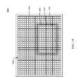
- FIG. 12illustrates a portion of an exemplary pixel array to which image pixels have been mapped to support a two-dimensional viewing configuration of an adaptable light manipulator in accordance with an embodiment.
- FIG. 13illustrates how image pixels are mapped to the portion of the pixel array shown in FIG. 12 to support a first three-dimensional viewing configuration of an adaptable light manipulator in accordance with an embodiment.
- FIG. 14illustrates how image pixels are mapped to the portion of the pixel array shown in FIGS. 12 and 13 to support a second three-dimensional viewing configuration of an adaptable light manipulator in accordance with an embodiment.
- FIG. 15is a block diagram of an exemplary display system that utilizes an adaptable parallax barrier and a light generator to support multiple viewing configurations in accordance with an embodiment.
- FIG. 16provides an exploded view of an exemplary display system that utilizes a controllable backlight array to provide regional luminosity control in accordance with an embodiment.
- FIG. 17is a block diagram of an exemplary display system that includes a pixel array disposed between a light generator and an adaptable parallax barrier in accordance with an embodiment.
- FIG. 18provides an exploded view of an exemplary display system that implements a regional brightness control scheme based on pixel intensity in accordance with an embodiment.
- FIG. 19illustrates a front perspective view of an exemplary display panel of a display system in accordance with an embodiment.
- FIG. 20illustrates two exemplary configurations of an adaptable light manipulator that includes a parallax barrier and a brightness regulation overlay in accordance with an embodiment.
- FIG. 21shows a perspective view of an exemplary adaptable lenticular lens that may be used in a displays system in accordance with an embodiment.
- FIG. 22shows a side view of the adaptable lenticular lens of FIG. 21 .
- FIG. 23is a block diagram of an exemplary implementation of a display system that includes an adaptable screen assembly that supports the simultaneous display of multiple visual presentations in accordance with an embodiment.
- FIGS. 24 , 27 , 28 , and 30depict exemplary systems that support independent viewer tailoring of same media source content via a common 2D-3D display in accordance with embodiments.
- FIG. 25is an exemplary control system that enables a viewer to independently tailor media content in accordance with an embodiment.
- FIG. 26illustrates first and second versions of video content in accordance with an embodiment.
- FIGS. 29 , 31 , and 32depict flowcharts of exemplary methods for supporting independent viewer tailoring of same media source content via a common 2D-3D display in accordance with embodiments.
- references in the specification to “one embodiment,” “an embodiment,” “an example embodiment,” etc.,indicate that the embodiment described may include a particular feature, structure, or characteristic, but every embodiment may not necessarily include the particular feature, structure, or characteristic. Moreover, such phrases are not necessarily referring to the same embodiment. Further, when a particular feature, structure, or characteristic is described in connection with an embodiment, it is submitted that it is within the knowledge of one skilled in the art to effect such feature, structure, or characteristic in connection with other embodiments whether or not explicitly described.
- versionsof video content may include any of the following: (i) two predefined constructs retrieved from one or more media sources; (ii) a first predefined construct from a media source that is delivered for a first viewer, and a time offset redisplay of such same construct that is delivered for a second viewer; (iii) a first predefined media construct from a media source and two time offset redisplays—one for each viewer; (iii) a first predefined construct from a media source that is delivered for a first viewer, and a “reconfigured” (e.g., transcoded, resolution reduced, 3Dx-n reduced, etc.) construct that is delivered for a second viewer; (iv) a first predefined construct from a media source that is reconfigured differently twice for a first and a second viewer; or (v) supplemental video content integrated within or sent with each version.
- two predefined constructsretrieved from one or more media sources
- a first independently controllable version of video contentis delivered to a first region of a screen
- a second independently controllable version of the video contentis delivered to a second region of the screen.
- the first region and the second regionoverlap at least in part.
- the deliverysupports simultaneous display by the screen of both the first independently controllable version of the video content for a first viewer but not a second viewer and the second independently controllable version of the video content for the second viewer but not the first viewer.
- both a first frame sequence and a second frame sequenceare delivered to a screen assembly for simultaneous display in at least a partially overlapping area of the screen assembly.
- the first frame sequenceis delivered to produce a first visual presentation for the first viewer but not for the second viewer.
- the second frame sequenceis delivered to produce a second visual presentation for the second viewer but not for the first viewer.
- Each of the first frame sequence and the second frame sequenceis based at least in part on the video frame sequence.
- a simultaneous display of(i) a first independently controllable version of video content in a first region of a screen for a first viewer but not for a second viewer, and (ii) a second independently controllable version of the video content in a second region of the screen for the second viewer but not for the first viewer are caused.
- the first region and the second regionat least partially overlap.
- a change to a characteristic of the first independently controllable versionis caused.
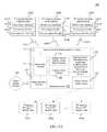
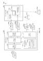
- FIG. 1Ais a block diagram of an exemplary system 100 that supports delivery of multiple private version views of single media content to respective viewers in accordance with an embodiment.
- a private version viewis a view that is intended to be viewed by specified viewer(s) but not by other viewer(s).
- system 100includes remote control devices 160 A- 160 N and media system(s) 170 .
- Remote control devices 160 A- 160 Nare used by the respective viewers to control respective private version views 186 A- 186 N of single media content 188 .
- Remote control devices 160 A- 160 Ninclude respective viewer input interfaces 162 A- 162 N, respective processing circuitry 164 A- 164 N, and respective communication circuitry 166 A- 166 N.
- Viewer input interfaces 162 A- 162 Nenable the respective viewers to provide input for controlling characteristics of the respective private version views 186 A- 186 N.
- a characteristicmay be a visual characteristic, a playback characteristic, or any other suitable type of characteristic. Examples of a visual characteristic include but are not limited to brightness, contrast, resolution, colorization, and a size of a screen region to which a private version view is delivered. Screen regions and visual characteristics thereof are described in greater detail below with reference to FIGS. 24 and 27 , for example.
- a playback characteristicindicates a manner in which a private version view is played back. Further detail regarding an exemplary remote control that enables viewer(s) to control playback characteristics of video content is provided below with reference to FIG. 25 .
- Processing circuitry 164 A- 164 Ngenerate respective input signals 168 A- 168 N that are based on the respective inputs from the viewers.
- Communication circuitry 166 A- 166 Ndeliver the respective input signals 168 A- 168 N to media system(s) 170 for processing.
- the input signals 168 A- 168 Nmay be provided via any suitable wired or wireless mechanism or communication pathway, including but not limited to a Bluetooth® pathway, an Institute of Electrical and Electronics Engineers® (IEEE) 802.11 pathway, a Digital Enhanced Cordless Telecommunications (DECT) pathway, etc.
- remote control device implementations for independently controlling multiple private version views that are simultaneously displayed by a screen assemblyare described in commonly-owned, co-pending U.S. patent application Ser. No. 12/982,078, filed on even date herewith and entitled “Multiple Remote Controllers That Each Simultaneously Controls a Different Visual Presentation of a 2D/3D Display,” the entirety of which is incorporated by reference herein.
- remote control devices 160 A- 160 Nare shown in FIG. 1A for illustrative purposes and are not intended to be limiting.
- the functionality of remote control devices 160 A- 160 N described abovemay instead be incorporated in respective smart phones, traditional computer input devices such as keyboards or mice, touch pads, gamepads or other type of gaming console input devices, etc.
- Media system(s) 170include remote control communication circuitry 172 , processing circuitry 174 , media interface circuitry 176 , management circuitry 178 , display driver circuitry 180 , and a viewing system 182 .
- Remote control communication circuitry 172receives the input signals 168 A- 168 N from respective remote control devices 160 A- 160 N. For instance, remote control communication circuitry 172 may decode the input signals 168 A- 168 N for further processing by processing circuitry 174 .
- Media interface circuitry 176receives the single media content 188 from a media source.
- Processing circuitry 174processes the single media content 188 based on the input signals 168 A- 168 N that are received via remote control communication circuitry 172 to provide respective private version views 186 A- 186 N of the single media content 188 .
- processing circuitry 174generates the first private version view 186 A in accordance with the first input signal 168 A; processing circuitry 174 generates the second private version view 186 B in accordance with the second input signal 168 B, and so on.
- Processing circuitry 174further generates control signals for controlling display driver circuitry 180 based on the input signals 168 A- 168 N.
- Management circuitry 178associates the private version views 186 A- 186 N with the respective viewers to whom the private version views 186 A- 186 N are to be presented.
- Display driver circuitry 180provides driver control signals for controlling characteristics of portions of viewing system 182 with which the respective viewers are associated basd on the control signals that are received from processing circuitry 174 . For instance, each viewer may be associated with respective shuttering eyewear and/or a respective portion of an adaptable light manipulating screen assembly.
- Viewing system 182supports simultaneous presentation of the private version views 186 A- 188 N toward the respective viewers via a single screen visual output 184 based on the driver control signals that are received from display driver circuitry 180 .
- viewing system 182may include an adaptable light manipulating screen assembly.
- FIG. 1Bis a block diagram of a viewing system 110 , which is an exemplary implementation of viewing system 182 of FIG. 1A , including a screen assembly 104 that utilizes an adaptable parallax barrier to support the simultaneous display of multiple visual presentations (e.g., multiple private version views), in accordance with an embodiment.
- Viewing system 110is shown to include driver circuitry 102 , which is an exemplary implementation of display driver circuitry 180 , for illustrative purposes and is not intended to be limiting. As shown in FIG.
- viewing system 110includes the aforementioned driver circuitry 102 and screen assembly 104 , wherein screen assembly 104 includes a pixel array 122 and an adaptable parallax barrier 124 .
- driver circuitry 102includes pixel array driver circuitry 112 and adaptable parallax barrier driver circuitry 114 .
- Pixel array 122comprises a two-dimensional array of pixels (e.g., arranged as a grid or other distribution) that operates to emit light 132 .
- Pixel array 122may comprise a self-illuminating or light-generating pixel array such that the pixels of pixel array 122 each emit light included in light 132 .
- each pixel in pixel array 122may operate to selectively pass light emitted by a backlighting source (not shown in FIG. 1B ) to produce light 132 .
- Each pixel of pixel array 122may be individually controllable to vary color and intensity.
- each pixel of pixel array 122may include a plurality of sub-pixels that correspond to separate color channels, such as a trio of red, green, and blue sub-pixels included in each pixel.
- Adaptable parallax barrier 124is positioned proximate to a surface of pixel array 122 .
- Barrier element array 142is a layer of adaptable parallax barrier 124 that includes a plurality of barrier elements or blocking regions arranged in an array. Each barrier element of the array is configured to be selectively opaque or transparent. Combinations of barrier elements may be configured to be selectively opaque or transparent to enable various effects.
- the states of the barrier elements of barrier element array 142may be configured such that light 132 emanating from pixel array 122 is filtered to produce filtered light 134 , wherein filtered light 134 includes one or more two-dimensional and/or three-dimensional images that may be viewed by viewers 136 in a viewing space 106 .
- each barrier elementmay have a round, square, or rectangular shape, and barrier element array 142 may have any number of rows of barrier elements that extend a vertical length of barrier element array 142 .
- each barrier elementmay have a “band” shape that extends a vertical length of barrier element array 142 , such that barrier element array 142 includes a single horizontal row of barrier elements.
- Each barrier elementmay include one or more of such bands, and different regions of barrier element array 142 may include barrier elements that include different numbers of such bands.
- barrier elementsmay be capable of being completely transparent or opaque, and in other embodiments, barrier elements may not be capable of being fully transparent or opaque.
- barrier elementsmay be capable of being 95% transparent when considered to be “transparent” and may be capable of being 5% transparent when considered to be “opaque.”
- Transparent and opaqueas used herein are intended to encompass barrier elements being substantially transparent (e.g., greater than 75% transparent, including completely transparent) and substantially opaque (e.g., less than 25% transparent, including completely opaque), respectively.
- Driver circuitry 102receives control signals 108 from control circuitry (not shown in FIG. 1B ).
- the control signals 108cause driver circuitry 102 to place screen assembly 104 in a selected one of a plurality of different viewing configurations.
- adaptable parallax barrier driver circuitry 114transmits drive signals 154 that cause barrier element array 142 to be placed in a state that supports the selected viewing configuration.
- the selected viewing configurationmay be a particular two-dimensional viewing configuration, a particular three-dimensional viewing configuration, or a viewing configuration that supports the simultaneous display of different types of two-dimensional and/or three-dimensional content.
- Viewing system 110is merely one exemplary implementation that includes an adaptable light manipulating screen assembly.
- Other exemplary implementations that include an adaptable light manipulating screen assemblyare described in detail below with reference to FIGS. 2-23 .
- FIG. 1Cis a block diagram of an exemplary system 120 in which shuttering eyewear support delivery of multiple private version views of single media content in accordance with an embodiment.
- system 120includes remote control devices 161 A- 161 N and media system(s) 171 .
- Remote control devices 161 A- 161 Nare used by the respective viewers to control respective private version views 197 A- 197 N of single media content 199 .
- Remote control devices 161 A- 161 Ninclude respective viewer input interfaces 163 A- 163 N, respective processing circuitry 165 A- 165 N, and respective communication circuitry 167 A- 167 N, which operate in like manner to viewer input interfaces 162 A- 162 N, processing circuitry 164 A- 164 N, and communication circuitry 166 A- 166 N described above with reference to FIG. 1A .
- communication circuitry 167 A- 167 Ndeliver input signals 169 A- 169 N that are generated by processing circuitry 165 A- 165 N based on respective viewer inputs that are received via viewer input interfaces 163 A- 163 N.
- the input signals 169 A- 169 Nmay be provided via any suitable wired or wireless mechanism or communication pathway, including but not limited to a Bluetooth® pathway, an Institute of Electrical and Electronics Engineers® (IEEE) 802.11 pathway, a Digital Enhanced Cordless Telecommunications (DECT) pathway, etc.
- IEEEInstitute of Electrical and Electronics Engineers®
- DECTDigital Enhanced Cordless Telecommunications
- Media system(s) 171include remote control communication circuitry 173 , media interface circuitry 175 , management circuitry 177 , processing circuitry 179 , and display driver circuitry 181 .
- Remote control communication circuitry 173receives the input signals 169 A- 169 N from respective remote control devices 161 A- 161 N. For instance, remote control communication circuitry 173 may decode the input signals 169 A- 169 N for further processing by processing circuitry 179 .
- Media interface circuitry 175receives the single media content 199 from a media source.
- Processing circuitry 179processes the single media content 199 based on the input signals 169 A- 169 N that are received via remote control communication circuitry 173 to provide respective private version views (e.g., private version views 197 A and 197 B) of the single media content 199 .
- processing circuitry 179generates the first private version view 197 A in accordance with the first input signal 169 A and the second private version view 197 B in accordance with the second input signal 169 B.
- Processing circuitry 179further generates control signals for controlling display driver circuitry 181 based on the input signals 169 A- 169 N.
- Management circuitry 177associates the private version views 197 A and 197 B with the respective first and second viewers to whom the private version views 197 A and 197 B are to be presented.
- Management circuitry 177provides information 185 A and 185 B regarding the respective private version views 197 A and 197 B to the respective first and second viewers' eyewear 187 A and 187 B.
- information 185 Amay include shuttering information for enabling first viewer's eyewear 187 A to present the first private version view 197 A and not the second private version view 197 B.
- Information 185 Bmay include shuttering information for enabling second viewer's eyewear 187 B to present the second private version view 197 B and not the first private version view 197 A.
- Display driver circuitry 181provides driver control signals for controlling a screen to display the first and second private version views 197 A and 197 B toward the first viewer's eyewear 187 A and the second viewer's eyewear 187 B via a single screen visual output 183 .
- the first and second viewers' eyewear 187 A and 187 Binclude respective communication circuitry 189 A and 189 B, respective processing circuitry 191 A and 191 B, respective shuttering circuitry 193 A and 193 B, and respective synchronization circuitry 195 A and 195 B.
- Communication circuitry 189 A and 189 Breceive respective information 185 A and 185 B from management circuitry 177 .
- Processing circuitry 191 Agenerates first control signals for controlling shuttering circuitry 193 A to pass the first private version view 197 A but not the second private version view 197 B based on the information 185 A.
- Processing circuitry 191 Bgenerates second control signals for controlling shuttering circuitry 193 B to pass the second private version view 197 B but not the first private version view 197 A based on the information 185 B.
- Shuttering circuitry 193 Aperforms shuttering by switching one or more lenses (not shown) of the first viewer's eyewear 187 A between a substantially transparent state and a substantially opaque state based on the first control signals to pass the first private version view 197 A but not the second private version view 197 B.
- Shuttering circuitry 193 Bperforms shuttering by switching one or more lenses (not shown) of the second viewer's eyewear 187 B between a substantially transparent state and a substantially opaque state based on the second control signals to pass the second private version view 197 B but not the first private version view 197 A.
- Synchronization circuitry 195 Asynchronizes the shuttering that is performed by shuttering circuitry 193 A with a frame rate of the first private version view 197 A.
- Synchronization circuitry 195 Bsynchronizes the shuttering that is performed by shuttering circuitry 195 B with a frame rate of the second private version view 197 B.
- Some exemplary display systemsthat include light manipulating screen assemblies for supporting simultaneous delivery of multiple private version views of single media content to respective viewers will now be described in subsections II.A. and II.B. These exemplary display systems are provided for illustrative purposes and are not intended to be limiting.
- FIG. 2shows an exemplary arrangement of an adaptable parallax barrier 200 that supports a particular three-dimensional viewing configuration.
- Adaptable parallax barrier 200is an example of adaptable parallax barrier 124 of FIG. 1B .
- adaptable parallax barrier 200includes a barrier element array 202 , which includes a plurality of barrier elements 204 arranged in a two-dimensional array.
- barrier element array 202includes a plurality of parallel strips of barrier elements 204 that are selected to be non-blocking to form a plurality of parallel non-blocking strips (or “slits”) 206 a - 206 g .
- slitsor “slitslitslits”
- non-blocking strips 206 a - 206 gare alternated with parallel blocking strips 208 a - 208 g of barrier elements 204 that are selected to be blocking.
- non-blocking strips 206 a - 206 g and blocking strips 208 a - 208 geach have a width (along the x-dimension) of two barrier elements 204 , and have lengths that extend along the entire y-dimension (twenty barrier elements 204 ) of barrier element array 202 , although in other embodiments, may have alternative dimensions.
- Non-blocking strips 206 a - 206 g and blocking strips 208 a - 208 gform a parallax barrier configuration for adaptable parallax barrier 200 .
- the spacing (and number) of parallel non-blocking strips 206 in barrier element array 202may be selectable by choosing any number and combination of particular strips of barrier elements 204 in barrier element array 202 to be non-blocking, to be alternated with blocking strips 208 , as desired. For example, hundreds, thousands, or even larger numbers of non-blocking strips 206 and blocking strips 208 may be present in adaptable parallax barrier 200 .
- FIG. 3shows an alternative example of an adaptable parallax barrier 300 that has also been configured to support a particular three-dimensional viewing configuration.
- adaptable parallax barrier 300includes a barrier element array 302 , which includes a plurality of barrier elements 304 arranged in a two-dimensional array (28 ⁇ 1 array).
- Barrier elements 304have widths (along the x-dimension) similar to the widths of barrier elements 204 in FIG. 2 , but have lengths that extend along the entire vertical length (y-dimension) of barrier element array 302 . As shown in FIG.
- barrier element array 302includes parallel non-blocking strips 306 a - 306 g alternated with parallel blocking strips 308 a - 308 g .
- parallel non-blocking strips 306 a - 306 g and parallel blocking strips 308 a - 308 geach have a width (along the x-dimension) of two barrier elements 304 , and have lengths that extend along the entire y-dimension (one barrier element 304 ) of barrier element array 302 .
- Each of adaptable parallax barriers 200 and 300configured in the manner shown in FIGS. 2 and 3 respectively, filter light produced or passed by a pixel array to form one or more three-dimensional views in a viewing space, thus supporting a three-dimensional viewing configuration.
- all of the barrier elements of either adaptable parallax barrier 200 or 300can simply be placed in a non-blocking state. Additional details concerning how the adaptable parallax barriers operate to support such three-dimensional viewing may be found, for example, in commonly-owned, co-pending U.S. patent application Ser. No. 12/845,409, filed on Jul. 28, 2010, and entitled “Display with Adaptable Parallax Barrier,” the entirety of which is incorporated by reference herein.
- the entirety of the barrier element arrayis filled with parallel non-blocking strips to support three-dimensional viewing.
- one or more regions of an adaptable parallax barriermay be filled with parallel non-blocking strips to deliver three-dimensional images, and one or more other regions of the adaptable parallax barrier may be rendered transparent to deliver two-dimensional images.
- a viewing configuration that mixes two-dimensional and three-dimensional viewing regionsmay be supported.
- FIG. 4shows an exemplary arrangement of an adaptable parallax barrier 400 that supports a viewing configuration that mixes two-dimensional and three-dimensional viewing regions according to example embodiments.
- Adaptable parallax barrier 400is similar to adaptable parallax barrier 200 of FIG. 2 , having barrier element array 202 including a plurality of barrier elements 204 arranged in a two-dimensional array.
- a first region 402 of barrier element array 202includes a plurality of parallel non-blocking strips alternated with parallel blocking strips that together fill first region 402 .
- a second region 404 of barrier element array 202is surrounded by first region 402 .
- Second region 404is a rectangular shaped region of barrier element array 202 that includes a two-dimensional array of barrier elements 204 that are non-blocking.
- barrier element array 202is configured to enable a three-dimensional image to be generated by pixels of a pixel array that are adjacent to barrier elements of first region 402 , and to enable a two-dimensional image to be generated by pixels of the pixel array that are adjacent to barrier elements inside of second region 404 .
- first region 402may include all non-blocking barrier elements 202 to pass a two-dimensional image
- second region 404may include parallel non-blocking strips alternated with parallel blocking strips to pass a three-dimensional image.
- adaptable parallax barrier 400may have additional numbers, sizes, and arrangements of regions configured to pass different combinations of two-dimensional images and three-dimensional images.
- different regions of an adaptable parallax barrier that have parallel non-blocking stripsmay have the parallel non-blocking strips oriented at different angles to deliver three-dimensional images to viewers that are oriented differently.
- a viewing configuration that mixes three-dimensional viewing regions having different viewing orientationsmay be supported.
- FIG. 5shows an exemplary arrangement of an adaptable parallax barrier 500 in which transparent slits have different orientations, according to an example embodiment.
- Adaptable parallax barrier 500is similar to adaptable parallax barrier 200 of FIG. 2 , having barrier element array 202 including a plurality of barrier elements 204 arranged in a two-dimensional array.
- a first region 510e.g., a bottom half
- barrier element array 202includes a first plurality of parallel strips of barrier elements 204 that are selected to be non-blocking to form a first plurality of parallel non-blocking strips 502 a - 502 e (each having a width of two barrier elements 204 ).
- FIG. 1shows an exemplary arrangement of an adaptable parallax barrier 500 in which transparent slits have different orientations
- parallel non-blocking strips 502 a - 502 eare alternated with parallel blocking strips 504 a - 504 f of barrier elements 204 (each having a width of three barrier elements 204 ).
- Parallel non-blocking strips 502 a - 502 eare oriented in a first direction (e.g., along a vertical axis).
- a second region 512(e.g., a top half) of barrier element array 202 includes a second plurality of parallel strips of barrier elements 204 that are selected to be non-blocking to form a second plurality of parallel non-blocking strips 506 a - 506 d (each having a width of one barrier element 204 ).
- parallel non-blocking strips 506 a - 506 dare alternated with parallel blocking strips 508 a - 508 c of barrier elements 204 (each having a width of two barrier elements 204 ).
- Parallel non-blocking strips 506 a - 506 dare oriented in a second direction (e.g., along a horizontal axis).
- first and second pluralities of parallel non-blocking strips 502 a - 502 e and 506 a - 506 dare present in barrier element array 202 that are oriented perpendicularly to each other.
- the region of barrier element array 202 that includes first plurality of parallel non-blocking strips 502 a - 502 emay be configured to deliver a three-dimensional image in a viewing space to be viewable by a user whose body is oriented vertically (e.g., sitting upright or standing up).
- the region of barrier element array 202 that includes second plurality of parallel non-blocking strips 506 a - 506 dmay be configured to deliver a three-dimensional image in a viewing space to be viewable by a user whose body is oriented horizontally (e.g., laying down). In this manner, users who are oriented differently relative to each other can still each be provided with a corresponding three-dimensional image that accommodates their position.
- Viewing system 110may be further configured to simultaneously generate multiple two-dimensional images or views for viewing by users in a viewing space.
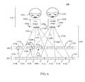
- FIG. 6shows an exemplary display system 600 configured to simultaneously deliver two different two-dimensional images to two different viewers, respectively, in accordance with an embodiment.
- Display system 600may comprise one implementation of viewing system 110 of FIG. 1B .
- display system 600includes a pixel array 602 and a barrier element array 604 .
- Pixel array 602includes a plurality of pixels 614 a - 614 d and 616 a - 616 d .
- Pixels 614alternate with pixels 616 , such that pixels 614 a - 614 d and 616 a - 616 d are arranged in series in the order of pixels 614 a , 616 a , 614 b , 616 b , 614 c , 616 c , 614 d , and 616 d .
- Further pixelsmay be included in pixel array 602 that are not visible in FIG. 6 , including further pixels along the width dimension of pixel array 602 (e.g., in the left-right directions) as well as pixels along a length dimension of pixel array 602 (not visible in FIG. 6 ).
- Each of pixels 614 a - 614 d and 616 a - 616 demits light, which emanates from a display surface 624 of pixel array 602 (e.g., generally upward in FIG. 6 ) towards barrier element array 604 .
- Some example indications of light emanating from pixels 614 a - 614 d and 616 a - 616 dare shown in FIG. 6 (as dotted lines), including light 624 a and light 618 a emanating from pixel 614 a , light 624 b , light 618 b , and light 624 c emanating from pixel 614 b , etc.
- Light emanating from pixel array 602is filtered by barrier element array 604 to form a plurality of images in a viewing space 626 , including a first image 632 a at a first location 636 a and a second image 632 b at a second location 636 b .
- a portion of the light emanating from pixel array 602is blocked by blocking barrier elements 610 , while another portion of the light emanating from pixel array 602 passes through non-blocking barrier elements 612 , according to the filtering by barrier element array 604 .
- light 624 a from pixel 614 ais blocked by blocking barrier element 610 a
- light 624 b and light 624 c from pixel 614 bare blocked by blocking barrier elements 610 b and 610 c , respectively.
- light 618 a from pixel 614 ais passed by non-blocking barrier element 612 a
- light 618 b from pixel 614 bis passed by non-blocking barrier element 612 b.
- System 600 shown in FIG. 6is configured to form first and second images 632 a and 632 b at locations 636 a and 636 b , respectively, which are positioned at a distance 628 from pixel array 602 .
- pixel array 602includes a first set of pixels 614 a - 614 d and a second set of pixels 616 a - 616 d .
- Pixels 614 a - 614 dcorrespond to first image 632 a and pixels 616 a - 616 d correspond to second image 632 b .
- first and second images 632 a and 632 bare formed at locations 636 a and 636 b , respectively.
- light 618 a - 618 d from the first set of pixels 614 a - 614 dis focused at location 636 a to form first image 6326 a at location 636 a .
- Light 620 a - 620 d from the second set of pixels 616 a - 616 dis focused at location 636 b to form second image 632 b at location 636 b.
- first viewer 634 areceives first image 632 a at first location 636 a and a second viewer 634 b receives second image 632 b at second location 636 b , according to an example embodiment.
- First and second images 632 a and 632 bmay each comprise a different two-dimensional image that may be viewed independently from each other.
- first image 632 a and second image 632 bmay be generated by display system 600 from first media content and second media content, respectively, that are independent of each other.
- First image 632 amay be received by both eyes of first viewer 634 a to be perceived by first viewer 634 a as a first two-dimensional image
- second image 632 bmay be received by both eyes of second viewer 634 b to be perceived by second viewer 634 b as a second two-dimensional image.
- first and second images 632 a and 632 bmay be generated to have a spacing that enables them to be separately viewed by first and second users 634 a and 634 b .
- first and second images 632 a and 632 bmay be delivered to different viewer locations as determined by a configuration of display system 600 , including a width and spacing of non-blocking slits in barrier element array 604 and by a spacing between pixel array 602 and barrier element array 604 .
- display system 600has a single viewing plane or surface (e.g., a plane or surface of pixel array 602 , barrier element array 604 , and/or display screen of display system 600 ) that supports multiple viewers with media content in the form of images or views.
- the single viewing plane of display system 600may provide a first two-dimensional view based on first two-dimensional media content to first viewer 634 a , and may provide a second two-dimensional view based on second two-dimensional media content to second viewer 634 b .
- Barrier element array 604causes the first media content to be presented to first viewer 634 a via a first area of the single viewing plane, but not to second viewer 634 b , while simultaneously causing the second media content to be presented to second viewer 634 b via a second area of the single viewing plane, but not to first viewer 634 a . Furthermore, the first area and second area of the single viewing plane that provide the first and second media content overlap each other at least in part, as barrier element array 604 enables both two-dimensional views to be provided from first set of pixels 614 a - 614 d and second set of pixels 616 a - 616 d , which are interleaved with each other. In accordance with certain configurations of display system 600 , the first and second areas may be the same area and the area may encompass the entirety of the display screen or surface of display system 600 or only a region of the display screen or surface of display system 600 .
- first and second viewers 634 a and 634 bmay each wear a pair of 3D-enabled glasses, and the first and second media content associated with first and second images 632 a and 632 b , respectively, may be three-dimensional media content.
- the 3D-enabled glassesmay be color filtering glasses.
- the color filter lenses of the glasses worn by first viewer 634 amay pass two-dimensional images (included in first image 632 a ) of differing perspective to the left and right eyes of first viewer 634 a to be perceived by first viewer 634 a as a first three dimensional image.
- the color filter lenses of the glasses worn by second viewer 634 bmay pass two-dimensional images (included in second image 632 b ) of differing perspective to the left and right eyes of second viewer 634 b to be perceived by second viewer 634 b as a second three dimensional image.
- the 3D-enabled glassesmay be shutter lensed glasses.
- the shutter lenses of the glasses worn by first viewer 634 amay be synchronized to pass two-dimensional images (included in first image 632 a ) of differing perspective to the left and right eyes of first viewer 634 a to be perceived by first viewer 634 a as a first three dimensional image.
- the shutter lenses of the glasses worn by second viewer 634 bmay be synchronized to pass two-dimensional images (included in second image 632 b ) of differing perspective to the left and right eyes of second viewer 634 b to be perceived by second viewer 632 b as a second three dimensional image.
- display system 600has a single viewing plane or surface (e.g., a plane or surface of pixel array 602 or barrier element array 604 ) that supports multiple viewers with media content in the form of three-dimensional images or views.
- the single viewing plane of display system 600may provide a first three-dimensional view based on first three-dimensional media content to first viewer 634 a , and may provide a second three-dimensional view based on second three-dimensional media content to second viewer 634 b .
- Barrier element array 604causes the first three-dimensional media content to be presented to first viewer 634 a via a first area of the single viewing plane, but not to second viewer 634 b , while simultaneously causing the second three-dimensional media content to be presented to second viewer 634 b via a second area of the single viewing plane, but not to first viewer 634 a . Furthermore, the first area and second area of the single viewing plane that provide the first and second media content overlap each other at least in part, as barrier element array 604 enables both three-dimensional views to be provided from first set of pixels 614 a - 614 d and second set of pixels 616 a - 616 d , which are interleaved with each other. In accordance with certain configurations of display system 600 , the first and second areas may be the same area and the area may encompass the entirety of the display screen or surface of display system 600 or only a region of the display screen or surface of display system 600 .
- display system 600can be configured to deliver a single two-dimensional or three-dimensional view to a viewer, to deliver a pair of two-dimensional views to a pair of viewers, or to deliver a pair of three-dimensional views to a pair of viewers.
- Display system 600can be configured to switch between delivering views to one and two viewers by turning off or turning on, respectively, the display of media content by pixel array 602 associated with one of the viewers (e.g., by turning off or on pixels 616 associated with second image 632 b ).
- Display system 600can be configured to switch between delivering two-dimensional and three-dimensional views by providing the corresponding media content type at pixel array 602 .
- Display systems in accordance with further embodimentsmay include multiple layers of parallax barriers. Such display systems may enable multiple three-dimensional images to be displayed in a viewing space.
- the multiple parallax barrier layersmay enable spatial separation of the images.
- a display device that includes multiple parallax barrier layersmay be configured to display a first three-dimensional image in a first region of a viewing space (e.g., a left-side area), a second three-dimensional image in a second region of the viewing space (e.g., a central area), a third three-dimensional image in a third region of the viewing space (e.g., a right-side area), etc.
- a display device that includes multiple parallax barrier layersmay be configured to display any number of spatially separated three-dimensional images as desired for a particular application (e.g., according to a number and spacing of viewers in the viewing space, etc.).
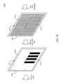
- FIG. 7is a block diagram of an exemplary display system 700 that includes multiple parallax barrier layers in accordance with an embodiment.
- display system 700includes driver circuitry 702 and a screen assembly 704 , wherein screen assembly 704 includes a pixel array 722 , a first parallax barrier 724 and a second parallax barrier 726 .
- first parallax barrier 724includes a first barrier element array 742
- second parallax barrier 726includes a second barrier element array 744 .
- driver circuitry 702includes pixel array driver circuitry 712 and parallax barrier driver circuitry 714 .
- Pixel array 722may comprise a self-illuminating or light-generating pixel array such that the pixels of pixel array 722 each emit light included in light 732 .
- each pixel in pixel array 722may operate to selectively pass light emitted by a backlighting source (not shown in FIG. 7 ) to produce light 732 .
- Pixel array driver circuitry 712may generate drive signals 752 based on a control signal 708 received from control circuitry (not shown in FIG. 7 ) and pixel array 722 may emit light 732 in accordance with the received drive signals 752 .
- pixel array driver circuitry 712may generate drive signals 752 to cause pixel array 722 to emit light 732 containing a plurality of images corresponding to different sets of pixels.
- First parallax barrier 724may be configured to filter light 732 received from pixel array 722 . As shown in FIG. 7 , first parallax barrier 724 includes first barrier element array 742 that filters light 732 to generate filtered light 734 . First barrier element array 742 may optionally be configurable to adjust the filtering performed by first parallax barrier 724 in a similar manner to that described above in regard to adaptable parallax barrier 124 or in another manner. In an embodiment, parallax barrier driver circuitry 714 may generate drive signals 754 based on control signal 708 received by driver circuitry 702 to cause first barrier element array 742 to filter light 732 as desired.
- Filtered light 734is received by second parallax barrier 726 to generate filtered light 736 that includes a plurality of three-dimensional images 762 1 - 762 n formed in a viewing space 706 .
- second parallax barrier 726includes second barrier element array 744 that filters filtered light 734 to generate filtered light 736 .
- Second barrier element array 744may optionally be configurable to adjust the filtering performed by second parallax barrier 726 in a similar manner to that described above in regard to adaptable parallax barrier 124 or in another manner.
- light manipulator driver circuitry 714may generate drive signals 756 based on control signal 708 to cause barrier element array 744 to filter filtered light 734 to generate filtered light 736 including three-dimensional images 762 1 - 762 n as desired.
- display system 700has a single viewing plane or surface (e.g., a plane or surface of pixel array 722 , first parallax barrier 724 , second parallax barrier 726 , or a display screen of display system 700 ) that supports multiple viewers with media content in the form of three-dimensional images or views.
- the single viewing plane of display system 700may provide a first three-dimensional view based on first three-dimensional media content to a first viewer, a second three-dimensional view based on second three-dimensional media content to a second viewer, and optionally further three-dimensional views based on further three-dimensional media content to further viewers.
- First and second parallax barrier 724 and 726cause each three-dimensional media content to be presented to a corresponding viewer via a corresponding area of the single viewing plane, with each viewer being enabled to view corresponding media content without viewing media content directed to other viewers.
- the areas of the single viewing plane that provide the various three-dimensional views of media contentoverlap each other at least in part.
- the areasmay be the same area—an area of a display screen or surface of display system 700 .
- the areasmay be the same area and the area may encompass the entirety of the display screen or surface of display system 700 or only a region of the display screen or surface of display system 700 .
- Display system 700may be configured in various ways to generate multiple three-dimensional images in embodiments. Furthermore, as described below, embodiments of display system 700 may be configured to generate two-dimensional views, as well as any combination of one or more two-dimensional views simultaneously with one or more three-dimensional views. Examples of such embodiments are provided in the following.
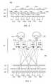
- FIG. 8shows a cross-sectional view of an exemplary display system 800 , which is an example implementation of system 700 shown in FIG. 7 .
- system 800includes a pixel array 802 , a first barrier element array 804 , and a second barrier element array 806 .
- System 800may also include display controller 702 of FIG. 7 , which is not shown in FIG. 8 for ease of illustration.
- System 800is described as follows.
- pixel array 802includes a first set of pixels 814 a - 814 c , a second set of pixels 816 a - 816 c , a third set of pixels 818 a - 818 c and a fourth set of pixels 820 a - 820 c .
- Pixels of the four sets of pixelsare alternated in pixel array 802 in the order of pixel 814 a , pixel 816 a , pixel 818 a , pixel 820 a , pixel 814 b , pixel 816 b , etc.
- Further pixelsmay be included in each set of pixels in pixel array 802 that are not visible in FIG. 8 , including hundreds, thousands, or millions of pixels in each set of pixels.
- Each of pixels 814 a - 814 c , 816 a - 816 c , 818 a - 818 c and 820 a - 820 cis configured to emit light, which emanates from the surface of pixel array 802 towards first barrier element array 804 .
- Each set of pixelsis configured to generate a corresponding image.
- FIG. 9shows display system 800 , where pixels of pixel array 802 emit light.
- Light from second set of pixels 816 a - 816 c and first set of pixels 814 a - 814 cis configured to generate third and fourth images 906 c and 906 d , respectively, which may be perceived together as a second three-dimensional image by a second viewer 904 b .
- Light from fourth set of pixels 820 a - 820 c and third set of pixels 818 a - 818 cis configured to generate first and second images 906 a and 906 b , respectively, which may be perceived together as a first three-dimensional image by a first viewer 904 a .
- the light emitted by the sets of pixelsis filtered by first and second barrier element arrays 804 and 806 to generate the first and second three-dimensional images in respective desired regions of a viewing space 902 adjacent to display system 800 .
- pixels 814 a - 814 ccorrespond to fourth image 906 d
- pixels 816 a - 816 ccorrespond to third image 906 c
- pixels 818 a - 818 ccorrespond to second image 906 b
- pixels 820 a - 820 ccorrespond to first image 906 a .
- light from the first set of pixels 814 a - 814 cforms fourth image 906 d and light from the third set of pixels 818 a - 818 c forms second image 906 b , due to the filtering of the non-blocking slits in first and second barrier element arrays 804 and 806 .
- light from the second set of pixels 816 a - 816 cforms third image 906 c and light from the fourth set of pixels 820 a - 820 c forms first image 906 a.
- first and second images 906 a and 906 bmay be configured to be perceived by viewer 904 a as a first three-dimensional image, such that first image 906 a is received at a right eye location 908 a of viewer 904 a and second image 906 b is received at a left eye location 908 b of viewer 904 a (e.g., separated by an interocular distance).
- third and fourth images 906 c and 906 dmay be configured to be perceived by viewer 904 b as a second three-dimensional image, such that third image 906 c is received at a right eye location 908 c of viewer 904 b and fourth image 906 d is received at a second eye location 908 d of viewer 904 b.
- First-fourth images 906 a - 906 dmay be formed in viewing space 902 at a distance from pixel array 802 and at a lateral location of viewing space 902 as determined by a configuration of display system 800 , including a width and spacing of non-blocking slits in first barrier element array 804 , by a width and positioning of non-blocking slits in second barrier element array 806 , by a spacing between pixel array 802 and first barrier element array 804 , and a spacing between first and second barrier element arrays 804 and 806 .
- display system 800may deliver a two-dimensional view to one of viewers 904 a and 904 b , and may simultaneously deliver a three-dimensional view to the other of viewers 904 a and 904 b .
- pixels 814 a - 814 c and pixels 816 a - 816 cmay deliver the same images (e.g., may display the same media content), such that third and fourth images 906 c and 906 d are the same.
- pixels 814 a - 814 cmay be turned off, and a width of slits 812 a , 812 c , and 812 e may be adjusted such that pixels 816 a - 816 c deliver a same view to both right and left eye locations 908 c and 908 d of viewer 904 b (through slits 824 a - 824 c ).
- first and second images 906 a and 906 bmay be simultaneously delivered to first viewer 904 a as differing perspective images to be perceived as a three-dimensional view or as the same image to be perceived as a second two-dimensional view.
- first barrier element array 804 and second barrier element array 806may be “turned off”
- first barrier element array 804 and second barrier element array 806may each transition all of their corresponding barrier elements to the non-blocking state (be “turned off”), and pixel array 802 may be configured to emit a single two-dimensional image.
- first barrier element array 804 and second barrier element array 806may transition all of its barrier elements to the non-blocking state, while the other of first barrier element array 804 and second barrier element array 806 may be configured to deliver a three-dimensional view.
- a configuration of adaptable parallax barrier 124 of viewing system 110 or a configuration of either of first and second parallax barrier 724 and 726 of display system 700can be dynamically modified to support a particular viewing configuration.
- the pixel array of each systemmust also be controlled to support the same viewing configuration.
- pixel array 122When a configuration of adaptable parallax barrier 124 of viewing system 110 is modified to support a particular viewing configuration, pixel array 122 must also be controlled to support the same viewing configuration. In particular, the rendering of pixels of an image (also referred to herein as “image pixels”) among the pixels of pixel array 122 (also referred to herein as “display pixels”) must be handled in a manner that is consistent with a current configuration of adaptable parallax barrier 124 .
- Thismay entail, for example, changing a number of display pixels that represents each image pixel (i.e., changing the resolution of a displayed image) and/or changing which display pixels or groups thereof correspond to the respective image pixels (i.e., changing the locations at which the image pixels are displayed), in response to modification of a configuration of adaptable parallax barrier 124 .
- Such changesmay be implemented by a controller (not shown in FIG. 1B ) via delivery of appropriate control signals 108 to pixel array driver circuitry 112 .
- pixel array driver circuitry 204when a configuration of adaptable parallax barrier 124 supports a first viewing configuration responsive to control signals 108 , pixel array driver circuitry 204 sends drive signals 152 in conformance with control signals 108 such that the rendering of images to pixel array 122 occurs in a manner that also supports the first viewing configuration. Furthermore, when the configuration of adaptable parallax barrier 124 is modified to support a second viewing configuration responsive to control signals 108 , pixel array driver circuitry 204 sends drive signals 152 in conformance with the control signals 108 such that the rendering of images to pixel array 122 occurs in a manner that also supports the second viewing configuration.
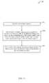
- FIG. 10depicts a flowchart 1000 of an exemplary method for controlling a pixel array to support the same viewing configuration as an adaptable light manipulator (such as adaptable parallax barrier 124 ) in accordance with an embodiment.
- the method of flowchart 1000begins at step 1002 .
- a configuration of an adaptable light manipulatorsuch as adaptable parallax barrier 124
- a number of display pixels in a pixel arraysuch as pixel array 122 , that represents each image pixel of a plurality of image pixels is changed in response to modifying the configuration of the adaptable light manipulator.
- FIGS. 12 and 13provide a simple illustration of an exemplary application of the method of flowchart 10 .
- a portion of a pixel array 1200includes a 16 ⁇ 16 array of display pixels.
- An example display pixelis shown as display pixel 1202 .
- each display pixelcomprises a trio of red, green, and blue sub-pixels as discussed above.
- a first imagecomprising a 4 ⁇ 4 array of image pixels (each shown depicting the letter “A” to indicate that each is included in the same image) is mapped to the display pixels such that 4 display pixels are used to present each image pixel.
- An example of an image pixelis shown as image pixel 1204 .
- the first imageis intended to represent an image that is viewed when an adaptable light manipulator disposed proximate to the pixel array is configured to support a two-dimensional viewing configuration.
- FIG. 13is intended to represent the same portion of pixel array 1200 after the configuration of the adaptable light manipulator has been changed to support a three-dimensional viewing configuration.
- the three-dimensional viewing configurationrequires the overlapping display of a first image and a second image across the same portion of pixel array 1200 .
- the pixel arrayis controlled such that 2 rather than 4 display pixels are used to present each image pixel of the first image (each still shown depicting the letter “A”). This corresponds to a decreased viewing resolution of the first image.
- the other half of the display pixelsare now used to present each image pixel of a second image (each shown depicting the letter “B”).
- the image pixels associated with the different imagesare aligned with the adaptable light manipulator to achieve a desired three-dimensional viewing effect.
- FIG. 11depicts a flowchart 1100 of another exemplary method for controlling a pixel array to support the same viewing configuration as an adaptable light manipulator (such as adaptable parallax barrier 124 ) in accordance with an embodiment.
- the method of flowchart 1100begins at step 1102 .
- a plurality of image pixelsis mapped to a plurality of respective first subsets of display pixels in a pixel array, such as pixel array 122 .
- a configuration of an adaptable light manipulator that is positioned proximate to the pixel arrayis changed.
- a slit pattern, orientation, or the like, of adaptable parallax barrier 124may be changed.
- a mapping of the plurality of image pixelsis changed from the plurality of respective first subsets of the display pixels to a plurality of respective second subsets of the display pixels in the pixel array to compensate for changing the configuration of the adaptable light manipulator.
- FIGS. 13 and 14provide a simple illustration of an exemplary application of the method of flowchart 1100 .
- a portion of a pixel array 1200is used to simultaneously display a first image comprising image pixels shown depicting the letter “A” and a second image comprising image pixels shown depicting the letter “B.”
- this display formatis utilized to support a three-dimensional viewing configuration corresponding to a particular arrangement of an adaptable light manipulator disposed proximate to the pixel array.
- FIG. 14is intended to represent the same portion of pixel array 1200 after the configuration of the adaptable light manipulator has been changed to support a modified three-dimensional viewing configuration (e.g., in response to a changed location of a viewer or some other factor).
- the modified three-dimensional viewing configurationrequires the display location of the first image and the second image to be shifted, as shown in FIG. 14 .
- the same image pixel 1304is now rendered to the bottom-most two display pixels in the second column from the left of array portion 1200 .
- FIG. 15shows a block diagram of yet another exemplary display system 1500 that utilizes an adaptable parallax barrier to support multiple viewing configurations.
- display system 1500includes driver circuitry 1502 and a screen assembly 1504 , wherein screen assembly 1504 include a light generator 1522 , an adaptable parallax barrier 1524 and a pixel array 1526 .
- driver circuitry 1502includes light generator driver circuitry 1512 , adaptable parallax barrier driver circuitry 1514 and pixel array driver circuitry 1516 .
- Light generator 1522emits light 1532 .
- Adaptable parallax barrier 1524is positioned proximate to light generator 1522 .
- Barrier element array 1544is a layer of adaptable parallax barrier 1524 that includes a plurality of barrier elements or blocking regions arranged in an array. Each barrier element of the array is configured to be selectively opaque or transparent.
- Barrier element array 1544filters light 1532 received from light generator 1522 to generate filtered light 1534 .
- Filtered light 1534is configured to enable a two-dimensional image, a three-dimensional image, or a pair of two-dimensional or three-dimensional images to be formed based on images subsequently imposed on filtered light 1534 by pixel array 1526 .
- Pixel array 1526includes a two-dimensional array of pixels (e.g., arranged in a grid or other distribution) like pixel array 122 of FIG. 1B .
- Pixel array 1526is not self-illuminating and operates as a light filter that imposes images (e.g., in the form of color, grayscale, etc.) on filtered light 1534 from adaptable parallax barrier 1524 to generate filtered light 1536 to include one or more images.
- Each pixel of pixel array 1526may be a separately addressable filter (e.g., a pixel of a plasma display, an LCD display, an LED display, or of other type of display).
- Each pixel of pixel array 1526may be individually controllable to vary the color imposed on the corresponding light passing through, and/or to vary the intensity of the passed light in filtered light 1536 .
- each pixel of pixel array 1526may include a plurality of sub-pixels that correspond to separate color channels, such as a trio of red, green, and blue sub-pixels included in each pixel.
- Driver circuitry 1502receives control signals 1508 from control circuitry (not shown in FIG. 15 ). Control signals 1508 cause driver circuitry 1502 to place screen 1504 in a selected one of a plurality of different viewing configurations. In particular, based on control signals 1508 , adaptable parallax barrier driver circuitry 1514 transmits drive signals 1554 that cause barrier element array 1544 to be placed in a state that supports the selected viewing configuration.
- pixel array driver circuitry 1516transmits drive signals 1556 to cause pixels of one or more images (also referred to herein as “image pixels”) to be rendered among the pixels of pixel array 1526 (also referred to herein as “display pixels”) in a manner that is consistent with a current configuration of adaptable parallax barrier 1524 .
- the selected viewing configurationmay be a particular two-dimensional viewing configuration, a particular three-dimensional viewing configuration, or a viewing configuration that supports the simultaneous display of different types of two-dimensional and/or three-dimensional content.
- conventional LCD displaystypically include a backlight and a display panel that includes an array of LCD pixels.
- the backlightis designed to produce a sheet of light of uniform luminosity for illuminating the LCD pixels.
- light generator 1522includes a backlight array 1542 which is a two-dimensional array of light sources. Such light sources may be arranged, for example, in a rectangular grid. Each light source in backlight array 1542 is individually addressable and controllable to select an amount of light emitted thereby.
- a single light sourcemay comprise one or more light-emitting elements depending upon the implementation.
- each light source in backlight array 1542comprises a single light-emitting diode (LED) although this example is not intended to be limiting.
- the amount of light emitted by the individual light sources that make up backlight array 1542can selectively controlled by drive signals 1552 generated by light generator driver circuitry 1512 so that the brightness associated with each of a plurality of display regions of screen 1504 can also be controlled.
- Thisenables display system 1500 to provide a desired brightness level for each display region automatically and/or in response to user input.
- backlight array 1542can be controlled such that a uniform level of brightness is achieved across different simultaneously-displayed display regions, even though the number of perceptible pixels per unit area varies from display region to display region.
- backlight array 1542can be controlled such that the level of brightness associated with a particular display region is increased or reduced without impacting (or without substantially impacting) the brightness of other simultaneously-displayed display regions.
- FIG. 16provides an exploded view of an exemplary display system 1600 that implements a controllable backlight array as described immediately above.
- Display system 1600comprises one implementation of display system 1500 .
- display system 1600includes a light generator 1602 that includes a backlight array 1612 , an adaptable parallax barrier 1604 that includes a barrier element array 1622 and a display panel 1606 that includes a pixel array 1632 . These elements may be aligned with and positioned proximate to each other to create an integrated screen assembly.
- a first portion 1634 of pixel array 1632 and a first portion 1624 of barrier element array 1622have been manipulated to create a first display region that displays multi-view three-dimensional content
- a second portion 1636 of pixel array 1632 and a second portion 1626 of barrier element array 1622have been manipulated to create a second display region that displays a three-dimensional image
- a third portion of 1638 of pixel array 1632 and a third portion 1628 of barrier element array 1622have been manipulated to create a third display region that displays a two-dimensional image.
- the amount of light emitted by light sources included within a first portion 1614 , a second portion 1616 and a third portion 1618 of backlight array 1612can respectively be controlled.
- the light sources within first portion 1614may be controlled to provide greater luminosity than the light sources within second portion 1616 and third portion 1618 as the number of perceivable pixels per unit area will be smallest in the first display region with which first portion 1614 is aligned.
- the light sources within second portion 1616may be controlled to provide greater luminosity than the light sources within third portion 1618 since the number of perceivable pixels per unit area will be smaller in the second display region with which second portion 1616 is aligned than the third display region with which third portion 1618 is aligned.
- the light sources within second portion 1616may be controlled to provide greater luminosity than the light sources within third portion 1618 since the number of perceivable pixels per unit area will be smaller in the second display region with which second portion 1616 is aligned than the third display region with which third portion 1618 is aligned.
- other control schemesmay be used.
- a display system in accordance with an embodimentcan dynamically manipulate pixel array 1632 and barrier element array 1622 in a coordinated fashion to dynamically and simultaneously create any number of display regions of different sizes and in different locations, wherein each of the created display regions can display one of two-dimensional, three-dimensional or multi-view three-dimensional content.
- backlight array 1612can also be dynamically manipulated in a coordinated fashion with pixel array 1632 and barrier element array 1622 to ensure that each display region is perceived at a desired level of brightness.
- each light source in backlight array 1612there is a one-to-one correspondence between each light source in backlight array 1612 and every display pixel in pixel array 1632 .
- the number of light sources provided in backlight array 1612is less than the number of pixels provided in pixel array 1632 .
- a single light sourcemay be provided in backlight array 1612 for every N pixels provided in pixel array 1632 , wherein N is an integer greater than 1.
- each light source in backlight array 1612may be arranged so that it provides backlighting for a particular group of pixels in pixel array 1632 , although this is only an example. In alternate embodiments, the number of light sources provided in backlight array 1612 is greater than the number of pixels provided in pixel array 1632 .
- light sources in backlight array 1612are described as being individually controllable. However, in alternate embodiments, light sources in backlight array 1612 may only be controllable in groups. This may facilitate a reduction in the complexity of the control infrastructure associated with backlight array 1612 . In still further embodiments, light sources in backlight array 1612 may be controllable both individually and in groups.
- FIGS. 15 and 16show display system configurations in which a barrier element array of an adaptable parallax barrier is disposed between a backlight array of individually addressable and controllable light sources and a pixel array
- the pixel arraymay be disposed between the backlight array and the barrier element array.
- FIG. 17is a block diagram of an exemplary display system 1700 that includes a pixel array 1724 disposed between a light generator 1722 that includes a backlight array 1742 and an adaptable parallax barrier 1726 that includes a barrier element array 1744 to support the generation of two-dimensional and/or three-dimensional images perceivable in a viewing space 1706 .
- selective control of the luminosity of groups or individual ones of the light sources in backlight array 1742may also be used to vary the backlighting luminosity associated with different display regions created by the interaction of backlight array 1742 , pixel array 1724 and barrier element array 1744 .
- FIG. 18provides an exploded view of an exemplary display system 1800 that implements a regional brightness control scheme based on pixel intensity as described immediately above.
- display system 1800includes a display panel 1802 and an adaptable parallax barrier 1804 .
- Display system 1800also includes a backlight panel, although this element is not shown in FIG. 18 . These elements may be aligned with and positioned proximate to each other to create an integrated display screen.
- display panel 1802includes a pixel array 1812 .
- Each of the pixels in a first portion 1814 of pixel array 1812is individually controlled by pixel array driver circuitry to pass a selected amount of light produced by a backlight panel (not shown in FIG. 18 ), thereby producing display-generated light representative of a single two-dimensional image.
- Each of the pixels in a second portion 1816 of pixel array 1812is individually controlled by the pixel array driver circuitry to pass a selected amount of light produced by the backlight panel, thereby producing display-generated light representative of two two-dimensional images that, when combined by the brain of a viewer positioned in an appropriate location relative to display system 1800 , will be perceived as a single three-dimensional image.
- Adaptable parallax barrier 1804includes barrier element array 1822 that includes a first portion 1824 and a second portion 1826 .
- Barrier element array 1822is aligned with pixel array 1814 such that first portion 1824 of blocking region array 1822 overlays first portion 1814 of pixel array 1812 and second portion 1826 of blocking region array 1822 overlays second portion 1816 of pixel array 1812 .
- Adaptable parallax barrier driver circuitrycauses all the barrier elements within first portion 1824 of barrier element array 1822 to be transparent. Thus, the two-dimensional image generated by the pixels of first portion 1814 of pixel array 1812 will simply be passed through to a viewer in a viewing space in front of display system 1400 .
- the adaptable parallax barrier driver circuitrymanipulates the barrier elements within second portion 1826 of blocking region array 1822 to form a plurality of parallel transparent strips alternated with parallel opaque strips, thereby creating a parallax effect that enables the two two-dimensional images generated by the pixels of second portion 1816 of pixel array 1812 to be perceived as a three-dimensional image by a viewer in the viewing space in front of display system 1800 .
- the pixels per unit area perceived by this viewer with respect to the two-dimensional imagewill be greater than the pixels per unit area perceived by this viewer with respect to the three-dimensional image.
- the two-dimensional imagewill appear brighter to the viewer than the three dimensional image when backlighting of constant luminosity is provided behind pixel array 1812 .
- drive signalsmay be transmitted to display panel 1802 that selectively cause the pixels included in first portion 1814 of pixel array 1812 to pass less light from the backlight panel (i.e., become less intense), thereby reducing the brightness of the two-dimensional image produced from the pixels in first portion 1814 of pixel array 1812 .
- drive signalsmay be transmitted to display panel 1802 that selectively cause the pixels included in second portion 1816 of pixel array 1812 to pass more light from the backlight panel (i.e., become more intense), thereby increasing the brightness of the three-dimensional image produced from the pixels in second portion 1816 of pixel array 1812 .
- the intensity of the pixels in portions 1814 and 1816 of pixel array 1812By controlling the intensity of the pixels in portions 1814 and 1816 of pixel array 1812 in this manner, the brightness of the two-dimensional image produced from the pixels in first portion 1814 of pixel array 1812 and the brightness of the three-dimensional image produced from the pixels in second portion 1816 of pixel array 1812 can be kept consistent. Additionally, by providing independent control over the intensity of the pixels in portions 1814 and 1816 of pixel array 1812 , independent control over the brightness of the two-dimensional and three-dimensional images generated therefrom can also be achieved.
- a display system in accordance with an embodimentcan dynamically manipulate pixel array 1812 and blocking element array 1822 in a coordinated fashion to dynamically and simultaneously create any number of display regions of different sizes and in different locations, wherein each of the created display regions can display one of two-dimensional, three-dimensional or multi-view three-dimensional content.
- the intensity of the pixels in pixel array 1812can also be dynamically manipulated in a coordinated fashion to ensure that each display region is perceived at a desired level of brightness.
- FIG. 19illustrates a front perspective view of an exemplary display panel 1900 .
- Display panel 1900includes a pixel array 1902 that includes a first portion 1904 and a second portion 1906 , wherein each of first portion 1904 and second portion 1906 includes a different subset of the pixels in pixel array 1902 . It is to be assumed that first portion 1904 of pixel array 1902 is illuminated by backlighting provided by an aligned first portion of a backlight array (not shown in FIG.
- Second portion 1906 of pixel array 1902is illuminated by backlighting provided by an aligned second portion of the backlight array.
- the amount of light emitted by each light source in the second portion of the backlight array to illuminate second portion 1906 of pixel array 1902is controlled such that it is greater than the amount of light emitted by each light source in the first portion of the backlight array to illuminate first portion 1904 of pixel array 1902 .
- This control schememay be applied, for example, to cause a three-dimensional image formed by interaction between the pixels in second portion 1906 of pixel array 1902 and an adaptable parallax barrier to appear to have a uniform brightness level with respect to a two-dimensional image formed by interaction between the pixels in first portion 1904 of pixel array 1902 and the adaptable parallax barrier.
- the difference in the amount of light emitted by each light source in the first and second portions of the backlight array to illuminate corresponding first and second portions 1904 and 1906 of pixel array 1902may also give rise to undesired visual artifacts.
- the differencemay cause pixels in boundary areas immediately outside of second portion 1906 of pixel array 1902 to appear brighter than desired in relation to other pixels in first portion 1904 of pixel array 1902 .
- the pixels in boundary area 1912 immediately outside of second portion 1906 of pixel array 1902may appear brighter than desired in relation to other pixels in first portion 1904 of pixel array 1902 .
- the differencemay cause pixels in boundary areas immediately inside of second portion 1906 of pixel array 1502 to appear dimmer than desired in relation to other pixels in second portion 1906 of pixel array 1902 .
- the pixels in boundary area 1914 immediately inside of second portion 1906 of pixel array 1902may appear dimmer than desired in relation to other pixels in second portion 1906 of pixel array 1902 .
- the reduced luminosity of the light sources in the first portion of the backlight arrayhas “spilled over” to impact the pixels in boundary area 1914 , causing those pixels to be dimmer than desired.
- an embodimentmay selectively control the amount of light passed by the pixels located in boundary region 1912 and/or boundary region 1914 to compensate for the undesired visual effects.
- driver circuitry associated with pixel array 1902may selectively cause the pixels included in boundary area 1912 of pixel array 1902 to pass less light from the backlight panel (i.e., become less intense), thereby reducing the brightness of the pixels in boundary area 1912 , thus compensating for an undesired increase in brightness due to “spill over” from light sources in the second portion of the backlight array.
- driver circuitry associated with pixel array 1902may selectively cause the pixels included in boundary area 1914 of pixel array 1902 to pass more light from the backlight panel (i.e., become more intense), thereby increasing the brightness of the pixels in boundary area 1914 , thus compensating for an undesired reduction in brightness due to “spill over” from light sources in the first portion of the backlight array.
- the intensity of the pixels in boundary areas 1912 and/or 1914in this manner, the undesired visual effects described above that can arise from the use of a backlight array to provide regional brightness control can be mitigated or avoided entirely.
- FIG. 19provides only one example of undesired visual effects that can arise from the use of a backlight array to provide regional brightness control.
- Persons skilled in the relevant art(s)will appreciate that many different display regions having many different brightness characteristics can be simultaneously generated by a display system in accordance with embodiments, thereby giving rise to different undesired visual effects relating to the brightness of boundary areas inside and outside of the different display regions. In each case, the intensity of pixels located in such boundaries areas can be selectively increased or reduced to mitigate or avoid such undesired visual effects.
- a regional brightness control schemeis implemented in a display system that does not include a backlight panel at all, but instead utilizes a display panel comprising an array of organic light emitting diodes (OLEDs) or polymer light emitting diodes (PLEDs) which function as display pixels and also provide their own illumination.
- Viewing system 110 described above in reference to FIG. 1Bmay be representative of such a system, provided that pixel array 122 comprises an array of OLEDs or PLEDs.
- the amount of light emitted by the individual OLED/PLED pixels that make up the OLED/PLED pixel arraycan be selectively controlled so that the brightness associated with each of a plurality of display regions of viewing system 110 can also be controlled.
- the OLED/PLED pixel arraycan be controlled such that a uniform level of brightness is achieved across different simultaneously-displayed display regions, even though the number of perceptible pixels per unit area varies from display region to display region.
- the OLED/PLED pixel arraycan be controlled such that the level of brightness associated with a particular display region is increased or reduced without impacting (or without substantially impacting) the brightness of other simultaneously-displayed display regions.
- OLED/PLED pixel regionssuch as those described above are adjacent to each other, it is possible that the brightness characteristics of one pixel region can impact the perceived brightness of an adjacent pixel region having different brightness characteristics, creating an undesired visual effect.
- a first OLED/PLED pixel region having a relatively high level of brightness to support the viewing of multi-view three-dimensional contentmay be adjacent to a second OLED/PLED pixel region having a relatively low level of brightness to support the viewing of two-dimensional content.
- light from pixels in a perimeter area of the first OLED/PLED pixel region that are close to the boundary between the two pixel regionsmay “spill over” into a perimeter area of the second OLED/PLED pixel region.
- pixels in the perimeter area of the second OLED/PLED pixel regionmay appear brighter than desired in relation to other pixels in the second OLED/PLED pixel region.
- pixels in the perimeter area of the first OLED/PLED pixel arraymay appear dimmer than desired in relation to other pixels in the first OLED/PLED pixel region because of the adjacency to the second OLED/PLED pixel region.
- a regional brightness control schemeis implemented in a display system that includes an adaptable parallax barrier that also supports brightness regulation via an “overlay” approach.
- an adaptable parallax barrierthat also supports brightness regulation via an “overlay” approach.
- Such an approachinvolves the use of a brightness regulation overlay that is either independent of or integrated with an adaptable parallax barrier.
- the brightness regulation overlayis used to help achieve the aforementioned goals of maintaining standard brightness across various regional screen configurations and compensating for or minimizing backlighting dispersion.
- the brightness regulation overlaycomprises an element that allows regional dimming through various tones of “grey” pixels.
- an adaptable parallax barrier and the brightness regulation overlayare implemented as a non-color (i.e., black, white and grayscale) LCD sandwich, although other implementations may be used.
- the combined adaptable parallax barrier and brightness regulation overlayprovide full transparent or opaque states for each pixel, as well as a grayscale alternative that can be used to “balance out” brightness variations caused by the parallax barrier itself.
- Control over the individual barrier elements of the parallax barrier and the individual grayscale pixels of the brightness regulation overlaymay be provided by using coordinated driver circuitry signaling.
- coordinate signalingmay cause the pixels of the adaptable parallax barrier and the brightness regulation overlay (collectively referred to below as the manipulator pixels) to create opaque and transparent barrier elements associated with a particular parallax barrier configuration and a grayscale support there between to allow creation of overlays.
- FIG. 20illustrates two exemplary configurations of an adaptable light manipulator 2000 that includes an adaptable parallax barrier and a brightness regulation overlay implemented as a light manipulating LCD sandwich with manipulator grayscale pixels.
- the grayscale pixelsmap to the display pixels on a one-to-one basis, but that need not be the case.
- a first exemplary configuration of adaptable light manipulator 2000is shown above the section line denoted with reference numeral 2002 .
- a three-dimensional region 2004is created with fully transparent or fully opaque manipulator pixels that provide parallax barrier functionality and a two-dimensional region 2006 is created having continuous medium gray manipulator pixels.
- the medium gray manipulator pixelsoperate to reduce the perceived brightness of two-dimensional region 2006 to better match that of three-dimensional region 2004 .
- two-dimensional region 2006could instead comprise a three-dimensional region having a number of views that is different than three-dimensional region 2004 , thus also requiring brightness regulation.
- boundary region compensationis performed.
- a boundary region 2010 within two-dimensional region 2006may be “lightened” to a light gray to compensate for any diminution of light that might occur near the boundary with three-dimensional region 2004 .
- the grayscale level of an inner portion 2008 of two-dimensional region 2006is maintained at the same medium gray level as in the portion of two-dimensional region 2006 above section line 2002 .
- a first boundary region 2012 and a second boundary region 2014 within three-dimensional region 2004comprise darker and lighter gray transitional areas, respectively, to account for light dispersion from two-dimensional region 2006 .
- an inner portion 2016 of three-dimensional region 2004includes only fully transparent or fully opaque manipulator pixels consistent with a parallax barrier configuration and no brightness regulation.
- the configuration of adaptable light manipulator 2000is achieved by first creating a white through various grayscale areas that correspond to the regions and boundary areas to be formed. Once established, the manipulator pixels in these areas that comprise the opaque portions of the parallax barrier are overwritten to turn them black.
- this two-stage approachis conceptual only and no “overwriting” need be performed.
- adaptable light manipulator 2000comprises the only component used in a display system for performing brightness regulation and/or boundary region compensation.
- the display systemfurther utilizes any one or more of the following aforementioned techniques for performing brightness regulation and/or boundary region compensation: a backlight array with independently-controllable light sources, and/or a pixel array and associated control logic for selectively increasing or decreasing the intensity of display pixels (e.g., either LCD pixels or OLED/PLED pixels).
- a backlight array with independently-controllable light sourcesand/or a pixel array and associated control logic for selectively increasing or decreasing the intensity of display pixels (e.g., either LCD pixels or OLED/PLED pixels).
- adaptable light manipulator 2000is implemented as an integrated adaptable parallax barrier and brightness regulation overlay.
- adaptable light manipulator 2000is implemented using an adaptable parallax barrier panel and an independent brightness regulation overlay panel.
- any of the non-uniform light generation schemes described abovemay also be used in conjunction with a display system that includes multiple parallax barriers, such as display system 700 of FIG. 7 , to support simultaneous presentation of regional two-dimensional, three-dimensional and multi-view three dimensional views.
- each region supported by such non-uniform light generationmay comprise a region that simultaneously presents multiple different two-dimensional and/or three-dimensional views to multiple respective viewers.
- an adaptable lenticular lensmay be used.
- adaptable parallax barrier 124may be replaced with an adaptable lenticular lens.
- first parallax barrier 724 or second parallax barrier 726may be replaced with a lenticular lens, such as an adaptable lenticular lens.
- FIG. 21shows a perspective view of an exemplary adaptable lenticular lens 2100 in accordance with an embodiment.
- adaptable lenticular lens 2100includes a sub-lens array 2102 .
- Sub-lens array 2102includes a plurality of sub-lenses 2104 arranged in a two-dimensional array (e.g., arranged side-by-side in a row).
- Each sub-lens 2104is shown in FIG. 21 as generally cylindrical in shape and having a substantially semi-circular cross-section, but in other embodiments may have other shapes.
- sub-lens array 2102is shown to include eight sub-lenses for illustrative purposes and is not intended to be limiting.
- sub-lens array 2102may include any number (e.g., hundreds, thousands, etc.) of sub-lenses 2104 .
- FIG. 22shows a side view of adaptable lenticular lens 2100 .
- lightmay be passed through adaptable lenticular lens 2100 in the direction of dotted arrow 2202 to be diverted.
- Adaptable lenticular lens 2100is adaptable in that it can be modified to manipulate light in different ways in order to accommodate different viewing configurations.
- adaptable lenticular lensis made from an elastic material and can be stretched or shrunk in one or more directions in response to generated drive signals.
- FIG. 23is a block diagram of an exemplary implementation of a display system 2300 that includes an adaptable screen assembly that supports the simultaneous display of multiple visual presentations in accordance with an embodiment.
- display system 2300generally comprises control circuitry 2302 , driver circuitry 2304 and an adaptable screen assembly 2306 .
- control circuitry 2302includes a processing unit 2314 , which may comprise one or more general-purpose or special-purpose processors or one or more processing cores.
- Processing unit 2314is connected to a communication infrastructure 2312 , such as a communication bus.
- Control circuitry 2302may also include a primary or main memory (not shown in FIG. 23 ), such as random access memory (RAM), that is connected to communication infrastructure 2312 .
- the main memorymay have control logic stored thereon for execution by processing unit 2314 as well as data stored thereon that may be input to or output by processing unit 2314 during execution of such control logic.
- Control circuitry 2302may also include one or more secondary storage devices (not shown in FIG. 23 ) that are connected to communication infrastructure 2312 , including but not limited to a hard disk drive, a removable storage drive (such as an optical disk drive, a floppy disk drive, a magnetic tape drive, or the like), or an interface for communicating with a removable storage unit such as an interface for communicating with a memory card, memory stick or the like.
- secondary storage devicesprovide an additional means for storing control logic for execution by processing unit 2314 as well as data that may be input to or output by processing unit 2314 during execution of such control logic.
- Control circuitry 2302further includes a user input interface 2318 , a viewer tracking unit 2316 , and a media interface 2320 .
- User input interface 2318is intended to generally represent any type of interface that may be used to receive user input, including but not limited to a remote control device, a traditional computer input device such as a keyboard or mouse, a touch screen, a gamepad or other type of gaming console input device, or one or more sensors including but not limited to video cameras, microphones and motion sensors.
- Viewer tracking unit 3216is intended to generally represent any type of functionality for determining or estimating a location of one or more viewers of display system 3200 and/or a head orientation of one or more viewers of display system 3200 .
- Viewer tracking unitmay perform such functions using different types of sensors (e.g., cameras, motion sensors, microphones or the like) or by using tracking systems such as those that wirelessly track an object (e.g., headset, remote control, or the like) currently being held or worn by a viewer.
- sensorse.g., cameras, motion sensors, microphones or the like
- tracking systemssuch as those that wirelessly track an object (e.g., headset, remote control, or the like) currently being held or worn by a viewer.
- Media interface 2320is intended to represent any type of interface that is capable of receiving media content such as video content or image content.
- media interface 2320may comprise an interface for receiving media content from a remote source such as a broadcast media server, an on-demand media server, or the like.
- media interface 2320may comprise, for example and without limitation, a wired or wireless internet or intranet connection, a satellite interface, a fiber interface, a coaxial cable interface, or a fiber-coaxial cable interface.
- Media interface 2320may also comprise an interface for receiving media content from a local source such as a DVD or Blu-Ray disc player, a personal computer, a personal media player, smart phone, or the like.
- Media interface 2320may be capable of retrieving video content from multiple sources.
- Control circuitry 2302further includes a communication interface 2322 .
- Communication interface 2322enables control circuitry 2302 to send control signals via a communication medium 2352 to another communication interface 2330 within driver circuitry 2304 , thereby enabling control circuitry 2302 to control the operation of driver circuitry 2304 .
- Communication medium 2352may comprise any kind of wired or wireless communication medium suitable for transmitting such control signals.
- driver circuitry 2304includes the aforementioned communication interface 2330 as well as pixel array driver circuitry 2332 and adaptable light manipulator(s) driver circuitry 2334 .
- Driver circuitryalso optionally includes light generator driver circuitry 2336 .
- Each of these driver circuitry elementsis configured to receive control signals from control circuitry 2302 (via the link between communication interface 2322 and communication interface 2330 ) and, responsive thereto, to send selected drive signals to a corresponding hardware element within adaptable screen assembly 2306 , the drive signals causing the corresponding hardware element to operate in a particular manner.
- pixel array driver circuitry 2332is configured to send selected drive signals to a pixel array 2342 within adaptable screen assembly 2306
- adaptable light manipulator(s) driver circuitry 2334is configured to send selected drive signals to one or more adaptable light manipulators 2344 within adaptable screen assembly 2306
- optional light generator driver circuitry 2336is configured to send selected drive signals to an optional light generator 2346 within adaptable screen assembly 2306 .
- processing unit 2314operates pursuant to control logic to receive media content via media interface 2320 and to generate control signals necessary to cause driver circuitry 2304 to render such media content to screen 2306 in accordance with a selected viewing configuration.
- processing unit 2314may operate pursuant to control logic to receive first and second media content via media interface 2320 and present the first and second media content via first and second simultaneously-displayed views of adaptable screen assembly 2306 to corresponding first and second viewers. For instance, at least the first view may be observable by the first viewer but not the second viewer.
- the control logic that is executed by processing unit 2314may be retrieved, for example, from a primary memory or a secondary storage device connected to processing unit 2314 via communication infrastructure 2312 as discussed above. The control logic may also be retrieved from some other local or remote source. Where the control logic is stored on a computer readable medium, that computer readable medium may be referred to herein as a computer program product.
- driver circuitry 2304may be controlled to send coordinated drive signals necessary for simultaneously displaying two-dimensional images, three-dimensional images and multi-view three-dimensional content via adaptable screen assembly 2306 .
- a manner by which pixel array 2642 , adaptable light manipulator 2644 (e.g., an adaptable parallax barrier), and light generator 2646 may be manipulated in a coordinated fashion to perform this functionis described in commonly-owned, co-pending U.S. patent application Ser. No. 12/982,031, filed on even date herewith and entitled “Coordinated Driving of Adaptable Light Manipulator, Backlighting and Pixel Array in Support of Adaptable 2D and 3D Displays,” the entirety of which is incorporated by reference herein. Note that in accordance with certain implementations (e.g., implementations in which pixel array comprises an OLED/PLED pixel array), adaptable screen assembly 2306 need not include light generator 2346 .
- At least part of the function of generating control signals necessary to cause pixel array 2342 , adaptable light manipulator 2344 and light generator 2346 to render media content to screen 2306 in accordance with a selected viewing configurationis performed by drive signal processing circuitry 2338 which is integrated within driver circuitry 2304 .
- Such circuitrymay operate, for example, in conjunction with and/or under the control of processing unit 2314 to generate the necessary control signals.
- control circuitry 2302 , driver circuitry 2304 and adaptable screen assembly 2306are all included within a single housing. For example and without limitation, all these elements may exist within a television, a laptop computer, a tablet computer, or a telephone.
- the link 2350 formed between communication interfaces 2322 and 2330may be replaced by a direct connection between driver circuitry 2304 and communication infrastructure 2312 .
- control circuitry 2302is disposed within a first housing, such as set top box or personal computer, and driver circuitry 2304 and adaptable screen assembly 2306 are disposed within a second housing, such as a television or computer monitor.
- the set top boxmay be any type of set top box including but not limited to fiber, Internet, cable, satellite, or terrestrial digital.
- FIG. 24depicts an exemplary system 2400 that provides such support in accordance with an embodiment.
- system 2400includes a display system 2402 and a screen 2404 .
- Display system 2402includes first interface circuitry 2410 , processing circuitry 2412 , second interface circuitry 2414 , control system 2416 , and audio circuitry 2418 .
- First interface circuitry 2410receives video content 2406 .
- first interface circuitry 2410may decode video content 2406 for further processing by processing circuitry 2412 .
- Video content 2406may comprise two-dimensional content, three-dimensional content, or a combination thereof.
- Processing circuitry 2412delivers via second interface circuitry 2414 both a first independently controllable version 2408 A of the video content 2406 to a first region 2420 A of screen 2404 and a second independently controllable version 2408 B of the video content 2406 to a second region 2420 B of screen 2404 .
- processing circuitry 2412may produce the first independently controllable version 2408 A and/or the second independently controllable version 2408 B based at least in part on the video content 2406 .
- first and second independently controllable versions 2408 A and 2408 Bmay be time-shifted (e.g., rewound or fast forwarded), paused, or otherwise modified (e.g., include supplemental content) with respect to the video content 2406 as received by first interface circuitry 2410 .
- first independently controllable version 2408 Amay be the video content 2406 with a first time offset
- second independently controllable version 2408 Bmay be the video content 2406 with a second time offset that is different from the first time offset.
- first or second independently controllable versions 2408 A or 2408 Bmay not be modified with respect to (i.e., may be the same as) the video content 2406 as received by first interface circuitry 2410 .
- first version of video contente.g., first independently controllable version 2408 A of video content 2406
- second version of the video contente.g., second independently controllable version 2408 B of video content 2406
- Processing circuitry 2412may include buffer circuitry (not shown) for buffering the first independently controllable version 2408 A of the video content 2406 and/or the second independently controllable version 2408 B of the video content 2406 .
- the buffer circuitrymay store a portion of the first independently controllable version 2408 A until the first independently controllable version 2408 A is no longer ahead of the second independently controllable version 2408 B with respect to time (e.g., until the first and second independently controllable versions 2408 A and 2408 B are synchronized).
- the buffer circuitrymay store a portion of the second independently controllable version 2408 B until the second independently controllable version 2408 B is no longer ahead of the first independently controllable version 2408 A with respect to time (e.g., until the first and second independently controllable versions 2408 A and 2408 B are synchronized).
- Processing circuitry 2412may be capable of invoking different pathway(s) via which the first independently controllable version 2408 A and/or the second independently controllable version 2408 B are to be received in response to determining that the first and second independently controllable versions 2408 A and 2408 B are not in synchrony. For example, if the first independently controllable version 2408 A is ahead of the second independently controllable version 2408 B with respect to time, processing circuitry 2412 may invoke a different pathway via which the second independently controllable version 2408 B is to be received. For instance, processing circuitry 2412 may invoke a new session, invoke a time-shared read of a disk, activate an additional head of a storage device, etc.
- processing circuitry 2412may invoke a different pathway via which the first independently controllable version 2408 A is to be received.
- processing circuitry 2412buffers content that is common between the first and second independently controllable versions 2408 A and 2408 B.
- processing circuitry 2412invokes a different pathway via which to receive non-common content of a time-delayed version of the video content 2406 .
- the non-common contentis content of the time-delayed version that is not common between the first and second independently controllable versions 2408 A and 2408 B.
- the time-delayed versionis the first independently controllable version if the second independently controllable version 2408 B is ahead of the first independently controllable version 2408 A with respect to time.
- the time-delayed versionis the second independently controllable version 2408 B if the first independently controllable version 2408 A is ahead of the second independently controllable version 2408 B with respect to time.
- Processing circuitry 2412may modify characteristic(s) of the first independently controllable version 2408 A and/or the second independently controllable version 2408 B in response to determining that the first and second independently controllable versions 2408 A and 2408 B are not in synchrony.
- processing circuitry 2412may reduce a resolution of the second independently controllable version 2408 B, reduce a number of perspectives represented by the second independently controllable version 2408 B, reduce a quality of service (QoS) that is associated with the second independently controllable version 2408 B, reduce a size of the second region 2420 B, and/or change a protocol that is used to deliver the second independently controllable version 2408 B until the first independently controllable version 2408 A is no longer ahead of the second independently controllable version 2408 B with respect to time.
- QoSquality of service
- processing circuitry 2412may reduce a resolution of the first independently controllable version 2408 A, reduce a number of perspectives represented by the first independently controllable version 2408 A, reduce a quality of service (QoS) that is associated with the first independently controllable version 2408 A, reduce a size of the first region 2420 A, and/or change a protocol that is used to deliver the first independently controllable version 2408 A until the second independently controllable version 2408 B is no longer ahead of the first independently controllable version 2408 A with respect to time.
- QoSquality of service
- processing circuitry 2412incorporates an indicator in the first independently controllable version 2408 A and/or in the second independently controllable version 2408 B to indicate whether the first and second independently controllable versions 2408 A and 2408 B are synchronized.
- processing circuitry 2412delivers the indicator via second interface circuitry 2414 in addition to the first and second independently controllable versions 2408 A and 2408 B.
- processing circuitry 2412may deliver the indicator to a region of screen 2404 for simultaneous display to both the first viewer 2426 A and the second viewer 2426 B.
- Control system 2416enables both a first viewer 2426 A to control the first independently controllable version 2408 A of the video content 2406 and a second viewer 2426 B to control the second independently controllable version 2408 B of the video content 2406 .
- control system 2416may enable the first viewer 2426 A and/or the second viewer 2426 B to provide input for controlling characteristic(s) of the first independently controllable version 2408 A and/or the second independently controllable version 2408 B.
- a characteristicmay be a visual characteristic, a playback characteristic, or any other suitable type of characteristic.
- Examples of a visual characteristicinclude but are not limited to brightness, contrast, resolution, colorization, and a size of a region to which the first independently controllable version 2408 A or the second independently controllable version 2408 B is delivered.
- a playback characteristicindicates a manner in which a version of video content (e.g., the first independently controllable version 2408 A and/or the second independently controllable version 2408 B) is played back. Further detail regarding an exemplary control system that enables viewer(s) to control playback characteristics of video content is provided below with reference to FIG. 25 .
- control system 2416may enable both the first viewer 2426 A and the second viewer 2426 B to control the first independently controllable version 2408 A. In another example, control system 2416 may enable the first viewer 2426 A but not the second viewer 2426 B to control the first independently controllable version 2408 A. In yet another example, control system 2416 may enable both the first viewer 2426 A and the second viewer 2426 B to control the second independently controllable version 2408 B. In still another example, control system 2416 may enable the second viewer 2426 B but not the first viewer 2426 A to control the second independently controllable version 2408 B.
- Control system 2416may be implemented as one or two user input interfaces, which may be integrated with processing circuitry 2412 or independent from processing circuitry 2412 .
- each of the one or two input interfacesmay include a smart phone, a remote control, a traditional computer input device such as a keyboard or mouse, a touch pad, a gamepad or other type of gaming console input device, etc.
- An exemplary control system that is implemented as a user input interface for illustrative purposesis described below with reference to FIG. 25 .
- Control system 2416may be communicatively coupled to processing circuitry 2412 via any suitable wired or wireless mechanism or communication pathway, including but not limited to a Bluetooth® pathway, an Institute of Electrical and Electronics Engineers® (IEEE) 802.11 pathway, a Digital Enhanced Cordless Telecommunications (DECT) pathway, etc.
- IEEEInstitute of Electrical and Electronics Engineers®
- DECTDigital Enhanced Cordless Telecommunications
- Some exemplary remote control device implementations for independently modifying multiple presentations that are simultaneously displayed by a screen assemblyare described in commonly-owned, co-pending U.S. patent application Ser. No. 12/982,078, filed on even date herewith and entitled “Multiple Remote Controllers That Each Simultaneously Controls a Different Visual Presentation of a 2D/3D Display,” the entirety of which is incorporated by reference herein.
- Audio circuitry 2418delivers both a first audio output 2424 A corresponding to the first independently controllable version 2408 A of the video content 2406 and a second audio output 2424 B corresponding to the second independently controllable version 2408 B of the video content 2406 .
- Audio circuitry 2418may include one or more viewer-specific speakers (e.g., an earbud or a headphone speaker) and/or one or more non-viewer-specific speakers (e.g., a speaker mounted in a door panel of a car or on a wall of a room).
- audio circuitry 2418may deliver the first audio output 2424 A to both the first viewer 2426 A and the second viewer 2426 B.
- audio circuitry 2418may deliver the first audio output 2424 A via non-viewer-specific speaker(s) and/or via first and second viewer-specific speaker(s) corresponding to the respective first and second viewers 2426 A and 2426 B.
- audio circuitry 2418may deliver the first audio output 2424 A via non-viewer-specific speaker(s) and via viewer-specific speaker(s) that correspond to either the first viewer 2426 A or the second viewer 2426 B.
- audio circuitry 2418may deliver the first audio output 2424 A to the first viewer 2426 A but not to the second viewer 2426 B. In accordance with this example, audio circuitry 2418 may deliver the first audio output 2424 A via viewer-specific speaker(s) that correspond to the first viewer 2426 A.
- audio circuitry 2418may deliver the second audio output 2424 B to both the first viewer 2426 A and the second viewer 2426 B.
- audio circuitry 2418may deliver the second audio output 2424 B via non-viewer-specific speaker(s) and/or via first and second viewer-specific speaker(s) corresponding to the respective first and second viewers 2426 A and 2426 B.
- audio circuitry 2418may deliver the second audio output 2424 B via non-viewer-specific speaker(s) and via viewer-specific speaker(s) that correspond to either the first viewer 2426 A or the second viewer 2426 B.
- audio circuitry 2418may deliver the second audio output 2424 B to the second viewer 2426 B but not to the first viewer 2426 A. In accordance with this example, audio circuitry 2418 may deliver the second audio output 2424 B via viewer-specific speaker(s) that correspond to the second viewer 2426 B.
- Screen 2404includes first region 2420 A and second region 2420 B.
- First and second regions 2420 A and 2420 Boverlap at least in part to provide an overlapping region 2422 .
- first and second regions 2420 A and 2420 Bmay overlap entirely, though the scope of the embodiments is not limited in this respect.
- First and second regions 2420 A and 2420 Bsimultaneously display the respective first and second independently controllable versions 2408 A and 2408 B of the video content 2406 .
- First region 2420 Adisplays the first independently controllable version 2408 A for first viewer 2426 A but not second viewer 2426 B.
- Second region 2420 Bdisplays the second independently controllable version 2408 B for second viewer 2426 B but not first viewer 2426 A.
- Screen 2404may be any suitable type of screen, including but not limited to an LCD screen, a plasma screen, a light emitting device (LED) screen (e.g., an OLED (organic LED) screen), etc.
- LEDlight emitting device
- screen 2404may include a pixel array (e.g., pixel array 122 , 722 , 1526 , 1724 , or 2342 ).
- Processing circuitry 2412may include pixel array driver circuitry (e.g., pixel array driver circuitry 112 , 712 , 1516 , or 2332 ) for controlling the pixel array.
- Processing circuitry 2412may control the pixel array driver circuitry to send drive signals to the pixel array to place the pixel array in a state that supports simultaneous display of both the first independently controllable version 2408 A for the first viewer 2426 A but not the second viewer 2426 B and the second independently controllable version 2408 B for the second viewer 2426 B but not the first viewer 2426 A.
- screen 2404includes one or more adaptable light manipulators (e.g., parallax barrier 124 , 724 , 726 , 1524 , and/or 1726 , and/or adaptable light manipulator 2344 ).
- processing circuitry 2412includes adaptable light manipulator driver circuitry (e.g., adaptable parallax barrier driver circuitry 114 , 714 , or 1514 , or adaptable light manipulator driver circuitry 2334 ) for controlling the adaptable light manipulator.
- processing circuitry 2412controls the adaptable light manipulator driver circuitry to send drive signals to the adaptable light manipulator to place the adaptable light manipulator in a state that supports simultaneous display of both the first independently controllable version 2408 A for the first viewer 2426 A but not the second viewer 2426 B and the second independently controllable version 2408 B for the second viewer 2426 B but not the first viewer 2426 A.
- screen 2404includes a light generator (e.g., light generator 1522 , 1722 , or 2346 ).
- processing circuitry 2412includes light generator driver circuitry (e.g., light generator driver circuitry 1512 or 2336 ) for controlling the light generator.
- processing circuitry 2412controls the light generator driver circuitry to send drive signals to the light generator to cause the light generator to produce light in a manner (e.g., a non-uniform manner) that supports simultaneous display of both the first independently controllable version 2408 A for the first viewer 2426 A but not the second viewer 2426 B and the second independently controllable version 2408 B for the second viewer 2426 B but not the first viewer 2426 A.
- the light generatormay be used in conjunction with an adaptable light manipulator.
- the light generatormay include a backlight array, and the adaptable light manipulator may include a barrier element array.
- processing circuitry 2412may control the light generator driver circuitry to send the drive signals to cause different levels of luminosity to be produced by respective portions of the backlight array that are aligned with respective portions of the barrier element array, as described above with reference to FIG. 16 .
- FIG. 25is an exemplary control system 2500 that enables a viewer to independently tailor media content in accordance with an embodiment.
- Control system 2500is shown to be implemented as a remote control device for illustrative purposes and is not intended to be limiting.
- control system 2500includes a display 2502 , a movement element 2504 , a synch progress element 2506 a synch indicator 2508 , a select element 2510 , and playback control elements 2520 .
- first independently controllable version of video contente.g., first independently controllable version 2408 A of video content 2406 in FIG. 24
- second independently controllable version of the video contente.g., second independently controllable version 2408 B of video content 2406
- User 2a second user
- Display 2502includes a first time marker 2552 that indicates a time instance that corresponds to a frame of the first independently controllable portion that is currently (or most recently) displayed for User 1 relative to a duration of the first independently controllable portion (e.g., a proportion of the first independently controllable portion that has been displayed for User 1 ).
- Display 2502also includes a second time marker 2554 that indicates a time instance that corresponds to a frame of the second independently controllable portion that is currently (or most recently) displayed for User 2 relative to a duration of the second independently controllable portion (e.g., a proportion of the second independently controllable portion that has been displayed for User 2 ).
- Display 2502also includes synch counter 2556 that indicates an amount of time that is estimated to pass until the first and second independently controllable versions are in synchrony.
- Directional control element 2504includes an up arrow 2512 , a down arrow 2514 , a left arrow 2516 , and a right arrow 2518 .
- Arrows 2512 , 2514 , 2516 , and 2518are selectable by the viewer to move a pointer that is displayed on a screen (e.g., screen 2404 ) up, down, left, or right, respectively.
- the pointermay appear on the screen in response to selection of a playback control element by the viewer.
- the viewermay use arrows 2512 , 2514 , 2516 , and 2518 to browse through a list of available values for a control that is associated with the selected playback control element. For instance, a value may become highlighted as the pointer overlaps with that value.
- the valuemay become de-highlighted once the pointer no longer overlaps with the value. Once the user has identified (highlighted) a value for the control, the viewer may select the identified value by selecting the select 2510 element. A detailed discussion of the playback control elements 2520 is provided below.
- Synch progress element 2506toggles display 2502 on and off. For instance, if display 2502 is turned on, the viewer may select synch progress element 2506 to turn display 2502 off. If display 2502 is turned off, the viewer may select synch progress element 2506 to turn display 2502 on.
- Synch indicator 2508indicates whether the first independently controllable version and the second independently controllable version are in synchrony. Synch indicator 2508 is not selectable by the viewer. Rather, synch indicator 2508 is in a first state (e.g., illuminated) if the first and second independently controllable versions are in synchrony, and synch indicator 2508 is in a second state (e.g., not illuminated) that is different from the first state if the first and second independently controllable versions are not in synchrony. Synch indicator 2508 is shown to be a visual indicator (e.g., a light emitting diode (LED)) for illustrative purposes and is not intended to be limiting. It will be recognized that synch indicator 2508 may emit sound(s), produce tactile sensations (e.g., vibrations), etc. to differentiate between the first and second states.
- a visual indicatore.g., a light emitting diode (LED)
- Playback control elements 2520are used to control playback of a specified version of the video content. For example, if control system 2500 is associated with the first independently controllable version of the video content but not the second independently controllable version of the video content, the specified version is the first independently controllable version. If control system 2500 is associated with the second independently controllable version but not the first independently controllable version, the specified version is the second independently controllable version. If control system 2500 is associated with both the first independently controllable version and the second independently controllable version, control system 2500 may include an element (not shown) for selecting the first independently controllable version or the second independently controllable version to be the specified version. Such an element may be used to toggle between using playback control elements 2520 to control playback of the first independently controllable version and using playback control elements 2520 to control of playback of the second independently controllable version.
- Playback control elements 2520include a rewind element 2522 , a play element 2524 , a fast forward element 2526 , a skip back element 2528 , a stop element 2530 , a skip forward element 2532 , a picture-in-picture (PIP) element 2534 , a pause element 2536 , a playback speed element 2538 , a closed captioning (CC) element 2540 , a number of cameras element 2542 , a camera selector element 2544 , a synchronize element 2546 , a synch rate element 2548 , and an audio selector element 2550 .
- Rewind element 2522is used to rewind the specified version of the video content.
- Play element 2524is used to play the specified version.
- selection of the play element 2524may cause rewinding or fast forwarding of the specified version to discontinue and the specified version to be played.
- Fast forward element 2526is used to fast forward the specified version.
- Skip back element 2528is used to rewind the specified version a predetermined number of frames.
- Stop element 2530is used to discontinue playing of the specified content.
- Skip forward element 2532is used to fast forward the specified version a predetermined number of frames.
- PIP element 2534is used to overlay second video content on the specified version of the first video content or to otherwise display the second video content in conjunction with the specified version.
- the second video contentmay include another version of the first video content.
- the viewermay select the PIP element 2534 to cause the overlaid second video content to be removed from the specified version.
- An illustration of second video content overlaid on a specified version of first video contentis shown in FIG. 26 and described in the corresponding text below.
- Pause element 2536is used to pause the specified version.
- Playback speed element 2538is used to cause a rate at which the specified version is played to decrease or increase. For instance, once the viewer selects the playback speed element 2538 , the viewer may use movement element 2504 to increase or decrease the rate at which the specified version is to playback.
- the specified versionmay be associated with an audio output. Changing the rate of playback may cause the audio output to be changed in order to remain synchronized with the specified version of the video content. Accordingly, increasing or decreasing the rate of playback may cause a pitch of the audio output to increase or decrease, respectively. Thus, increasing or decreasing the rate of the playback may trigger audio correcting functionality (e.g., in processing circuitry 2412 ) that is associated with the playback speed element 2538 to counter such change in pitch of the audio output.
- audio correcting functionalitye.g., in processing circuitry 2412
- increasing the rate of playbackmay cause the pitch of the audio output to be reduced to counter an increase in pitch that occurs due to the increase in the playback rate.
- decreasing the rate of playbackmay cause the pitch of the audio output to be increased to counter a decrease in pitch that occurs due to the decrease in the playback rate.
- the audio correcting functionalitymay cancel pitch changes that are associated with changing the playback rate of the specified version.
- Closed caption (CC) element 2540is used to overlay closed caption message(s) on the specified version of the video content or to otherwise display the closed caption message(s) in conjunction with the specified version. Once the CC element 2540 is selected, the viewer may select the CC element 2540 again to cause the closed caption message(s) to be removed from the specified version.
- An illustration of a closed caption message overlaid on a specified version of video contentis shown in FIG. 26 and described in the corresponding text below.
- “Number of cameras” element 2542enables the viewer to select a number of perspective views that are to be represented by the specified version of the video content. For instance, once the viewer selects the “number of cameras” element 2542 , the viewer may use arrows 2512 , 2514 , 2516 , and 2518 to identify a number of perspective views. The viewer may select the select element 2510 to select the identified number of perspective views to be represented by the specified version. For example, if the specified version of the video content represents a single perspective view, the specified version is referred to as a 2D version of the video content. If the specified version of the video content represents two perspective views, the specified version is referred to as a 3D2 version of the video content. If the specified version of the video content represents four perspective views, the specified version is referred to as a 3D4 version of the video content, and so on.
- Camera selector element 2544enables the viewer to choose which perspective views of a designated number of perspective views are to be represented by the specified version of the video content. For instance, once the viewer selects the camera selector element 2544 , the viewer may use arrows 2512 , 2514 , 2516 , and 2518 to identify which perspective views are to be represented by the specified version. The viewer may select the select element 2510 to select the identified perspective views.
- Synchronize element 2546is used to cause the specified version of the video content and a non-specified version of the video content to become synchronized. For example, if the specified version is ahead of the non-specified version with respect to time, selection of the synchronize element 2546 may cause a rate of playback of the specified version to decrease and/or a rate of playback of the non-specified version to increase. In another example, if the specified version is behind the non-specified version with respect to time, selection of the synchronize element 2546 may cause the rate of playback of the specified version to increase and/or the rate of playback of the non-specified version to decrease. Selection of the synchronize element 2546 may cause the audio correcting functionality described above with reference to playback speed element 2538 to be invoked.
- selection of the synchronize element 2546may cause the specified version and the non-specified version to become synchronized substantially instantaneously.
- the specified version and the non-specified versionmay become synchronized without changing the rate of playback of the specified version and without changing the rate of playback of the non-specified version.
- the specified version and the non-specified versionmay become synchronized without causing the aforementioned audio correcting functionality to be invoked.
- Synch rate element 2548enables the viewer to control the rate at which the specified version of the video content synchronizes with the non-specified version of the video content. For example, if the specified version is ahead of the non-specified version with respect to time, the viewer may use arrows 2512 , 2514 , 2516 , and 2518 to decrease the rate of playback of the specified version to increase the rate of synchronization. In accordance with this example, the viewer may use arrows 2512 , 2514 , 2516 , and 2518 to increase the rate of playback of the specified version to decrease the rate of synchronization.
- the viewermay use arrows 2512 , 2514 , 2516 , and 2518 to increase the rate of playback of the specified version to increase the rate of synchronization.
- the viewermay use arrows 2512 , 2514 , 2516 , and 2518 to decrease the rate of playback of the specified version to decrease the rate of synchronization.
- Audio selector element 2550enables the viewer to select audio content that is to be associated with the specified version of the video content. Once the audio selector element 2550 is selected, the viewer may use arrows 2512 , 2514 , 2516 , and 2518 to browse through references to available audio. For example, the viewer may replace audio that is related to the specified version of the video content with other audio, which is not related to the specified version. In other example, the viewer may replace such other audio with the audio that is related to the specified version of the video content.
- Selection of any of the playback control elements 2520 , movement element 2504 , and select element 2510 by the viewercauses a control signal to be delivered to processing circuitry 2412 for further processing.
- Each of the aforementioned elementsmay be a button, an icon on a display, or any other interface element that is suitable for receiving input from the viewer.
- the aforementioned elementsare shown to be visual elements that are controllable and/or selectable using tactile input from the user. It will be recognized that the elements may be audibly controlled and/or selected using audible commands from the user.
- control system 2500may include elements in addition to or in lieu of playback control elements 2520 .
- control system 2500may include element(s) for controlling visual characteristic(s), such as brightness, contrast, resolution, colorization, etc. of the specified version of the video content, a size of a region to which the specified version is delivered, and so on.
- Control system 2500may include element(s) for adding any suitable type of supplemental content to the specified version of the video content.
- the PIP element 2534 and the CC element 2540may be used to add supplemental video content and closed caption message(s), respectively, to the specified version.
- Other elementsmay be used to add instant messages, alerts, program information, a clock, interactive graphical elements, or other type of supplemental content.
- supplemental media contentmay be overlaid upon or otherwise displayed in conjunction with a version of video content.
- a set-top boxthat is capable of retrieving such supplemental media content and delivering it to a screen assembly is described in commonly-owned, co-pending U.S. patent application Ser. No. 12/982,062, filed on even date herewith and entitled “Set-Top Box Circuitry Supporting 2D and 3D Content Reductions to Accommodate Viewing Environment Constraints,” the entirety of which is incorporated by reference herein.
- FIG. 26provides an illustration of the use of supplemental media content.
- FIG. 26illustrates first and second independently controllable versions 2602 and 2604 of video content in accordance with an embodiment.
- First independently controllable version 2602depicts a view of an ocean.
- Second independently controllable version 2604includes supplemental content that is not included in the first independently controllable version 2602 .
- second independently controllable version 2604includes overlays 2606 and 2608 on top of the view of the ocean that is depicted in first independently controllable version 2604 .
- Overlay 2606includes second video content that depicts a car positioned in front of a building. Accordingly, the second video content is unrelated to the first video content, which depicts the view of the ocean. However, it will be recognized that overlay 2606 or any other overlay may include video content that is related to the first video content. It will also be recognized that a viewer may select the picture-in-picture (PIP) element 2534 described above with reference to FIG. 25 , for example, to cause overlay 2606 to be included on top of (i.e., overlaid on) the view of the ocean in second independently controllable version 2604 .
- PIPpicture-in-picture
- Overlay 2608includes a closed caption message. It will be recognized that the viewer may select the closed caption (CC) element 2540 described above with reference to FIG. 25 , for example, to cause overlay 2608 to be overlaid on the view of the ocean in second independently controllable version 2604 .
- CCclosed caption
- FIG. 27depicts another exemplary system 2700 that supports independent viewer tailoring of same media source content via a common 2D-3D display in accordance with an embodiment.
- system 2700includes display system 2702 and screen 2704 .
- Display system 2702includes first interface circuitry 2710 , processing circuitry 2712 , and second interface circuitry 2714 , which are capable of operating in like manner to first interface circuitry 2410 , processing circuitry 2412 , and second interface circuitry 2414 , respectively, as described above with reference to FIG. 24 .
- first interface circuitry 2710receives video content 2706 .
- Processing circuitry 2712is capable of delivering via second interface circuitry 2714 both a first independently controllable version of the video content 2706 to a first region 2720 A of screen 2704 and a second independently controllable version of the video content 2706 to a second region 2720 B of screen 2704 .
- processing circuitry 2712determines that the first independently controllable version and the second independently controllable version are substantially in synchrony.
- the first independently controllable version and the second independently controllable versionmay be substantially the same and may be substantially time-aligned.
- the first and second independently controllable versionsare deemed to be substantially the same when they include substantially the same content.
- Processing circuitry 2712delivers via second interface circuitry 2714 a single version 2708 of the video content 2706 to the first and second regions 2720 A and 2720 B of screen 2704 , based at least in part on the first independently controllable version and the second independently controllable version being substantially in synchrony.
- Screen 2704includes first region 2720 A and second region 2720 B.
- First and second regions 2720 A and 2720 Boverlap at least in part to provide an overlapping region 2722 .
- First and second regions 2720 A and 2720 Bsimultaneously display the single version 2708 of the video content 2706 .
- First region 2720 Adisplays the single version 2708 for first viewer 2726 A but not second viewer 2726 B.
- Second region 2720 Bdisplays the single version 2708 for second viewer 2726 B but not first viewer 2726 A.
- FIG. 28depicts yet another exemplary system 2800 that supports independent viewer tailoring of same media source content via a common 2D-3D display in accordance with an embodiment.
- system 2800includes display system 2802 and screen 2804 .
- Display system 2802includes first interface circuitry 2810 , processing circuitry 2812 , and second interface circuitry 2814 , which operate in like manner to first interface circuitry 2710 , processing circuitry 2712 , and second interface circuitry 2714 , respectively, as described above with reference to FIG. 27 .
- processing circuitry 2812determines that the first independently controllable version of the video content 2806 and the second independently controllable version of video content 2806 are substantially in synchrony
- processing circuitry 2812delivers via second interface circuitry 2814 a single version 2808 of the video content 2806 to a common region 2820 of screen 2804 , rather than to regions that correspond to the respective viewers 2826 A and 2826 B.
- Processing circuitry 2812delivers the single version 2808 based at least in part on the first independently controllable version and the second independently controllable version being substantially in synchrony.
- Screen 2804includes common region 2820 .
- Common region 2820displays the single version 2808 for both the first viewer 2826 A and the second viewer 2726 B.
- FIG. 29depicts a flowchart 2900 of an exemplary method for supporting independent viewer tailoring of same media source content via a common 2D-3D display in accordance with an embodiment.
- Flowchart 2900may be performed by any of systems 2400 , 2700 , or 2800 shown in respective FIG. 24 , 27 , or 28 , for example.
- the method of flowchart 2900is not limited to those embodiments. Further structural and operational embodiments will be apparent to persons skilled in the relevant art(s) based on the discussion regarding flowchart 2900 .
- step 2902video content is received.
- first interface circuitry 2410 , 2710 , or 2810receives video content 2406 , 2706 , or 2806 .
- a first independently controllable version of the video contentis delivered to a first region of a screen, and a second independently controllable version of the video content is delivered to a second region of the screen.
- the first region and the second regionoverlap at least in part.
- the deliverysupports simultaneous display by the screen of both the first independently controllable version of the video content for a first viewer but not a second viewer and the second independently controllable version of the video content for the second viewer but not the first viewer.
- processing circuitry 2412 , 2712 , or 2812delivers via second interface circuitry 2414 , 2714 , or 2814 both a first independently controllable version 2408 A of video content 2406 to a first region 2420 A and a second independently controllable version 2408 B of the video content 2406 to a second region 2420 B.
- the deliverysupports simultaneous display by screen 2404 of both the first independently controllable version 2408 A of the video content 2406 for a first viewer 2426 A but not a second viewer 2426 B and the second independently controllable version 2408 B of the video content 2406 for the second viewer 2426 B but not the first viewer 2426 A.
- first region 2420 A and second region 2420 Boverlap at least in part.
- both a first audio output corresponding to the first independently controllable version of the video content and a second audio output corresponding to the second independently controllable version of the video contentare delivered.
- audio circuitry 2418delivers both a first audio output 2424 A corresponding to the first independently controllable version 2408 A of the video content 2406 and a second audio output 2424 B corresponding to the second independently controllable version 2408 B of the video content 2406 .
- processing circuitry 2412 , 2712 , or 2812determines whether the first independently controllable version 2408 A and the second independently controllable version 2408 B of the video content 2406 are substantially in synchrony. If the first independently controllable version of the video content and the second independently controllable version of the video content are substantially in synchrony, flow continues to step 2910 . Otherwise, flowchart 2900 ends.
- processing circuitry 2412 , 2712 , or 2812delivers a single version 2708 or 2808 of the video content 2706 or 2806 .
- one or more steps 2902 , 2904 , 2906 , 2908 , and/or 2910 of flowchart 2900may not be performed. Moreover, steps in addition to or in lieu of steps 2902 , 2904 , 2906 , 2908 , and/or 2910 may be performed.
- FIG. 30depicts still another exemplary system 3000 that supports independent viewer tailoring of same media source content via a common 2D-3D display in accordance with an embodiment.
- system 3000includes a media circuitry 3002 and a screen 3004 .
- Media circuitry 3002includes first interface circuitry 3010 , control circuitry 3012 , second interface circuitry 3014 , viewer interface circuitry 3016 , and audio circuitry 3018 .
- First interface circuitry 3010receives video frame sequence 3006 .
- first interface circuitry 3010may decode video frame sequence 3006 before providing the video frame sequence 3006 to control circuitry 3012 .
- Control circuitry 3012delivers both a first frame sequence 3008 A and a second frame sequence 3008 B via second interface circuitry 3014 to screen assembly 3004 for simultaneous display in at least a partially overlapping area 3022 of screen assembly 3004 .
- the first frame sequence 3008 Ais delivered to produce a first visual presentation 3020 A for a first viewer 3026 A but not for a second viewer 3026 B.
- the second frame sequence 3008 Bis delivered to produce a second visual presentation 3020 B for the second viewer 3026 B but not for the first viewer 3026 A.
- Control circuitry 3012may include buffer circuitry (not shown) for buffering the first frame sequence 3008 A and/or the second frame sequence 3008 B, though the scope of the embodiments is not limited in this respect.
- Each of the first frame sequence 3008 A and the second frame sequence 3008 Bis based at least in part on the video frame sequence 3006 .
- control circuitry 3012may produce the first frame sequence 3008 A and/or the second frame sequence 3008 B based at least in part on the video frame sequence 3006 .
- one or both of the first and second frame sequences 3008 A and 3008 Bmay be time-shifted (e.g., rewound or fast forwarded), paused, or otherwise modified (e.g., include supplemental content) with respect to the video frame sequence 3006 as received by first interface circuitry 3010 .
- the first frame sequence 3008 Amay be the video frame sequence 3006 with a first time offset
- the second frame sequence 3008 Bmay be the video frame sequence 3006 with a second time offset that is different from the first time offset.
- one of the first or second frame sequences 3008 A or 3008 Bmay not be modified with respect to (i.e., may be the same as) the video frame sequence 3006 as received by first interface circuitry 3010 .
- the first frame sequence 3008 Amay include supplemental content that is not included in the second frame sequence 3008 B, or vice versa.
- Viewer interface circuitry 3016enables the first viewer 3026 A to control at least one characteristic of the first visual presentation 3020 A. Viewer interface circuitry 3016 may also enable the second viewer 3026 B to control at least one characteristic of the second visual presentation 3020 B. For instance, viewer interface circuitry 3016 is shown in FIG. 30 to include a first portion 3028 A and a second portion 3028 B. First portion 3028 A supports the first viewer 3026 A in changing at least one characteristic of the first visual presentation 3020 A. For example, first portion 3028 A may enable the first viewer 3026 A to provide input for controlling characteristic(s) of the first visual presentation 3020 A.
- a characteristic of a visual presentationmay include but is not limited to a playback characteristic, such as those described above with reference to playback control elements 2520 of FIG.
- the second portion 3028 Bsupports the second viewer 3026 B in changing at least one characteristic of the second visual presentation 3020 B.
- second portion 3028 Bmay enable the second viewer 3026 B to provide input for controlling characteristic(s) of the second visual presentation 3020 B.
- Audio circuitry 3018delivers both a first audio output 3024 A corresponding to the first frame sequence 3008 A and a second audio output 3024 B corresponding to the second frame sequence 3008 B.
- FIGS. 31 and 32depict flowcharts of other exemplary methods for supporting independent viewer tailoring of same media source content via a common 2D-3D display in accordance with embodiments.
- Flowchart 3100may be performed by system 3000 shown in FIG. 30 , for example.
- Flowchart 3200may be performed by any of systems 2400 , 2700 , or 2800 shown in respective FIG. 24 , 27 , or 28 , for example.
- the methods of flowcharts 3100 and 3200are not limited to those embodiments. Further structural and operational embodiments will be apparent to persons skilled in the relevant art(s) based on the discussion regarding flowcharts 3100 and 3200 .
- step 3102a video frame sequence is received.
- first interface circuitry 3010receives video frame sequence 3006 .
- both a first frame sequence and a second frame sequenceare delivered to a screen assembly for simultaneous display in at least a partially overlapping area of the screen assembly.
- the first frame sequenceis delivered to produce a first visual presentation for a first viewer but not for a second viewer.
- the second frame sequenceis delivered to produce a second visual presentation for the second viewer but not for the first viewer.
- Each of the first frame sequence and the second frame sequenceis based at least in part on the video frame sequence.
- control circuitry 3012delivers both a first frame sequence 3008 A and a second frame sequence 3008 B via second interface circuitry 3014 to a screen assembly 3004 for simultaneous display in at least a partially overlapping area 3022 of screen assembly 3004 .
- the first frame sequence 3008 Ais delivered to produce a first visual presentation 3020 A for a first viewer 3026 A but not for a second viewer 3026 B.
- the second frame sequence 3008 Bis delivered to produce a second visual presentation 3020 B for the second viewer 3026 B but not for the first viewer 3026 A.
- each of the first frame sequence 3008 A and the second frame sequence 3008 Bis based at least in part on the video frame sequence 3006 .
- both a first audio output corresponding to the first frame sequence and a second audio output corresponding to the second frame sequenceare delivered.
- audio circuitry 3018delivers both a first audio output 3024 A corresponding to the first frame sequence 3008 A and a second audio output 3024 B corresponding to the second frame sequence 3008 B.
- one or more steps 3102 , 3104 , and/or 3106 of flowchart 3100may not be performed. Moreover, steps in addition to or in lieu of steps 3102 , 3104 , and/or 3106 may be performed.
- step 3202a first independently controllable version of video content is generated by processing the video content.
- processing circuitry 2412 , 2712 , or 2812generates a first independently controllable version 2408 A of video content 2406 , 2706 , or 2806 by processing the video content 2406 , 2706 , or 2806 .
- a second independently controllable version of the video contentis generated by processing the video content.
- processing circuitry 2412 , 2712 , or 2812generates a second independently controllable version 2408 B of the video content 2406 , 2706 , or 2806 by processing the video content 2406 , 2706 , or 2806 .
- a simultaneous display of(i) the first independently controllable version of the video content in a first region of a screen for a first viewer but not for a second viewer, and (ii) the second independently controllable version of the video content in a second region of the screen for the second viewer but not for the first viewer, is caused.
- the first region and the second regionat least partially overlap.
- processing circuitry 2412 , 2712 , or 2812causes at least in part a simultaneous display of (i) the first independently controllable version 2408 A of the video content 2406 , 2706 , or 2806 in a first region 2420 A of a screen 2404 , 2704 , or 2804 for a first viewer 2426 A but not for a second viewer 2426 B, and (ii) the second independently controllable version 2408 B of the video content 2406 , 2706 , or 2806 in a second region 2420 B of the screen 2404 , 2704 , or 2804 for the second viewer 2426 B but not for the first viewer 2426 A.
- First region 2420 A and second region 2420 Bat least partially overlap.
- both a first audio output that corresponds to the first independently controllable version of the video content and a second audio output that corresponds to the second independently controllable version of the video contentare made available.
- audio circuitry 2418makes available both a first audio output 2424 A that corresponds to the first independently controllable version 2408 A of the video content 2406 , 2706 , or 2806 and a second audio output 2424 B that corresponds to the second independently controllable version 2408 B of the video content 2406 , 2706 , or 2806 .
- a responseis made to a control signal that corresponds to an input from the first viewer.
- the control signalrelates to a change in a characteristic of the first independently controllable version.
- the characteristicmay be a visual characteristic, such as brightness, contrast, resolution, colorization, etc. of the first independently controllable version or a size of the first region of the screen in which the first independently controllable version is displayed.
- the characteristicmay be a playback characteristic, such as a time-shift, a playback rate, a number of perspectives, selected perspectives of a designated number of perspectives, supplemental content, or audio that is associated with the first independently controllable version.
- processing circuitry 2412 , 2712 , or 2812responds to a control signal that corresponds to an input from the first viewer 2426 A.
- the change to the characteristic of the first independently controllable versionis caused.
- an addition of supplemental content to the first independently controllable versionmay be caused.
- a change in a time-shift, a playback rate, or audio that is associated with the first independently controllable versionmay be caused.
- a change of perspectives and/or number thereof that are represented by the first independently controllable versionmay be caused.
- a change in brightness, contrast, resolution, colorization, etc. of the first independently controllable versionmay be caused.
- processing circuitry 2412 , 2712 , or 2812causes at least in part the change to the characteristic of the first independently controllable version 2408 A.
- processing circuitry 2412 , 2712 , or 2812causes at least in part the termination of the simultaneous display.
- processing circuitry 2412 , 2712 , or 2812causes at least in part a display of a single version 2708 or 2808 of the video content 2406 , 2706 , or 2806 .
- one or more steps 3202 , 3204 , 3206 , 3208 , 3210 , 3212 , 3214 , and/or 3216 of flowchart 3200may not be performed.
- steps in addition to or in lieu of steps 3202 , 3204 , 3206 , 3208 , 3210 , 3212 , 3214 , and/or 3216may be performed.
Landscapes
- Engineering & Computer Science (AREA)
- Signal Processing (AREA)
- Multimedia (AREA)
- Physics & Mathematics (AREA)
- Theoretical Computer Science (AREA)
- General Physics & Mathematics (AREA)
- Computer Hardware Design (AREA)
- Human Computer Interaction (AREA)
- General Engineering & Computer Science (AREA)
- Acoustics & Sound (AREA)
- Testing, Inspecting, Measuring Of Stereoscopic Televisions And Televisions (AREA)
- Controls And Circuits For Display Device (AREA)
- Compression Or Coding Systems Of Tv Signals (AREA)
Abstract
Description
Claims (22)
Priority Applications (1)
| Application Number | Priority Date | Filing Date | Title |
|---|---|---|---|
| US12/982,362US9049440B2 (en) | 2009-12-31 | 2010-12-30 | Independent viewer tailoring of same media source content via a common 2D-3D display |
Applications Claiming Priority (8)
| Application Number | Priority Date | Filing Date | Title |
|---|---|---|---|
| US29181809P | 2009-12-31 | 2009-12-31 | |
| US30311910P | 2010-02-10 | 2010-02-10 | |
| US12/774,307US8964013B2 (en) | 2009-12-31 | 2010-05-05 | Display with elastic light manipulator |
| US12/774,225US20110157322A1 (en) | 2009-12-31 | 2010-05-05 | Controlling a pixel array to support an adaptable light manipulator |
| US12/845,440US20110157697A1 (en) | 2009-12-31 | 2010-07-28 | Adaptable parallax barrier supporting mixed 2d and stereoscopic 3d display regions |
| US12/845,409US20110157696A1 (en) | 2009-12-31 | 2010-07-28 | Display with adaptable parallax barrier |
| US12/845,461US8767050B2 (en) | 2009-12-31 | 2010-07-28 | Display supporting multiple simultaneous 3D views |
| US12/982,362US9049440B2 (en) | 2009-12-31 | 2010-12-30 | Independent viewer tailoring of same media source content via a common 2D-3D display |
Publications (2)
| Publication Number | Publication Date |
|---|---|
| US20110157471A1 US20110157471A1 (en) | 2011-06-30 |
| US9049440B2true US9049440B2 (en) | 2015-06-02 |
Family
ID=43797724
Family Applications (27)
| Application Number | Title | Priority Date | Filing Date |
|---|---|---|---|
| US12/774,225AbandonedUS20110157322A1 (en) | 2009-12-31 | 2010-05-05 | Controlling a pixel array to support an adaptable light manipulator |
| US12/774,307Active2032-01-14US8964013B2 (en) | 2009-12-31 | 2010-05-05 | Display with elastic light manipulator |
| US12/845,409AbandonedUS20110157696A1 (en) | 2009-12-31 | 2010-07-28 | Display with adaptable parallax barrier |
| US12/845,461Active2031-10-30US8767050B2 (en) | 2009-12-31 | 2010-07-28 | Display supporting multiple simultaneous 3D views |
| US12/845,440AbandonedUS20110157697A1 (en) | 2009-12-31 | 2010-07-28 | Adaptable parallax barrier supporting mixed 2d and stereoscopic 3d display regions |
| US12/982,309Active2033-05-02US9204138B2 (en) | 2009-12-31 | 2010-12-30 | User controlled regional display of mixed two and three dimensional content |
| US12/982,047AbandonedUS20110157330A1 (en) | 2009-12-31 | 2010-12-30 | 2d/3d projection system |
| US12/982,362Active2031-02-05US9049440B2 (en) | 2009-12-31 | 2010-12-30 | Independent viewer tailoring of same media source content via a common 2D-3D display |
| US12/982,053AbandonedUS20110157309A1 (en) | 2009-12-31 | 2010-12-30 | Hierarchical video compression supporting selective delivery of two-dimensional and three-dimensional video content |
| US12/982,248AbandonedUS20110157315A1 (en) | 2009-12-31 | 2010-12-30 | Interpolation of three-dimensional video content |
| US12/982,031Active2032-12-14US9019263B2 (en) | 2009-12-31 | 2010-12-30 | Coordinated driving of adaptable light manipulator, backlighting and pixel array in support of adaptable 2D and 3D displays |
| US12/982,124Active2033-02-08US9124885B2 (en) | 2009-12-31 | 2010-12-30 | Operating system supporting mixed 2D, stereoscopic 3D and multi-view 3D displays |
| US12/982,020AbandonedUS20110157257A1 (en) | 2009-12-31 | 2010-12-30 | Backlighting array supporting adaptable parallax barrier |
| US12/982,199Active2032-09-27US8988506B2 (en) | 2009-12-31 | 2010-12-30 | Transcoder supporting selective delivery of 2D, stereoscopic 3D, and multi-view 3D content from source video |
| US12/982,273Active2032-08-13US9979954B2 (en) | 2009-12-31 | 2010-12-30 | Eyewear with time shared viewing supporting delivery of differing content to multiple viewers |
| US12/982,212Active2032-04-05US9013546B2 (en) | 2009-12-31 | 2010-12-30 | Adaptable media stream servicing two and three dimensional content |
| US12/982,140AbandonedUS20110161843A1 (en) | 2009-12-31 | 2010-12-30 | Internet browser and associated content definition supporting mixed two and three dimensional displays |
| US12/982,173Active2033-08-22US9143770B2 (en) | 2009-12-31 | 2010-12-30 | Application programming interface supporting mixed two and three dimensional displays |
| US12/982,062Active2032-06-13US8687042B2 (en) | 2009-12-31 | 2010-12-30 | Set-top box circuitry supporting 2D and 3D content reductions to accommodate viewing environment constraints |
| US12/982,088Active2032-01-06US9066092B2 (en) | 2009-12-31 | 2010-12-30 | Communication infrastructure including simultaneous video pathways for multi-viewer support |
| US12/982,156Active2035-11-09US9654767B2 (en) | 2009-12-31 | 2010-12-30 | Programming architecture supporting mixed two and three dimensional displays |
| US12/982,330AbandonedUS20110157326A1 (en) | 2009-12-31 | 2010-12-30 | Multi-path and multi-source 3d content storage, retrieval, and delivery |
| US12/982,377AbandonedUS20110157327A1 (en) | 2009-12-31 | 2010-12-30 | 3d audio delivery accompanying 3d display supported by viewer/listener position and orientation tracking |
| US12/982,069Active2033-05-07US8922545B2 (en) | 2009-12-31 | 2010-12-30 | Three-dimensional display system with adaptation based on viewing reference of viewer(s) |
| US14/504,095AbandonedUS20150015668A1 (en) | 2009-12-31 | 2014-10-01 | Three-dimensional display system with adaptation based on viewing reference of viewer(s) |
| US14/616,130AbandonedUS20150156473A1 (en) | 2009-12-31 | 2015-02-06 | Transcoder supporting selective delivery of 2d, stereoscopic 3d, and multi-view 3d content from source video |
| US14/723,922AbandonedUS20150264341A1 (en) | 2009-12-31 | 2015-05-28 | Communication infrastructure including simultaneous video pathways for multi-viewer support |
Family Applications Before (7)
| Application Number | Title | Priority Date | Filing Date |
|---|---|---|---|
| US12/774,225AbandonedUS20110157322A1 (en) | 2009-12-31 | 2010-05-05 | Controlling a pixel array to support an adaptable light manipulator |
| US12/774,307Active2032-01-14US8964013B2 (en) | 2009-12-31 | 2010-05-05 | Display with elastic light manipulator |
| US12/845,409AbandonedUS20110157696A1 (en) | 2009-12-31 | 2010-07-28 | Display with adaptable parallax barrier |
| US12/845,461Active2031-10-30US8767050B2 (en) | 2009-12-31 | 2010-07-28 | Display supporting multiple simultaneous 3D views |
| US12/845,440AbandonedUS20110157697A1 (en) | 2009-12-31 | 2010-07-28 | Adaptable parallax barrier supporting mixed 2d and stereoscopic 3d display regions |
| US12/982,309Active2033-05-02US9204138B2 (en) | 2009-12-31 | 2010-12-30 | User controlled regional display of mixed two and three dimensional content |
| US12/982,047AbandonedUS20110157330A1 (en) | 2009-12-31 | 2010-12-30 | 2d/3d projection system |
Family Applications After (19)
| Application Number | Title | Priority Date | Filing Date |
|---|---|---|---|
| US12/982,053AbandonedUS20110157309A1 (en) | 2009-12-31 | 2010-12-30 | Hierarchical video compression supporting selective delivery of two-dimensional and three-dimensional video content |
| US12/982,248AbandonedUS20110157315A1 (en) | 2009-12-31 | 2010-12-30 | Interpolation of three-dimensional video content |
| US12/982,031Active2032-12-14US9019263B2 (en) | 2009-12-31 | 2010-12-30 | Coordinated driving of adaptable light manipulator, backlighting and pixel array in support of adaptable 2D and 3D displays |
| US12/982,124Active2033-02-08US9124885B2 (en) | 2009-12-31 | 2010-12-30 | Operating system supporting mixed 2D, stereoscopic 3D and multi-view 3D displays |
| US12/982,020AbandonedUS20110157257A1 (en) | 2009-12-31 | 2010-12-30 | Backlighting array supporting adaptable parallax barrier |
| US12/982,199Active2032-09-27US8988506B2 (en) | 2009-12-31 | 2010-12-30 | Transcoder supporting selective delivery of 2D, stereoscopic 3D, and multi-view 3D content from source video |
| US12/982,273Active2032-08-13US9979954B2 (en) | 2009-12-31 | 2010-12-30 | Eyewear with time shared viewing supporting delivery of differing content to multiple viewers |
| US12/982,212Active2032-04-05US9013546B2 (en) | 2009-12-31 | 2010-12-30 | Adaptable media stream servicing two and three dimensional content |
| US12/982,140AbandonedUS20110161843A1 (en) | 2009-12-31 | 2010-12-30 | Internet browser and associated content definition supporting mixed two and three dimensional displays |
| US12/982,173Active2033-08-22US9143770B2 (en) | 2009-12-31 | 2010-12-30 | Application programming interface supporting mixed two and three dimensional displays |
| US12/982,062Active2032-06-13US8687042B2 (en) | 2009-12-31 | 2010-12-30 | Set-top box circuitry supporting 2D and 3D content reductions to accommodate viewing environment constraints |
| US12/982,088Active2032-01-06US9066092B2 (en) | 2009-12-31 | 2010-12-30 | Communication infrastructure including simultaneous video pathways for multi-viewer support |
| US12/982,156Active2035-11-09US9654767B2 (en) | 2009-12-31 | 2010-12-30 | Programming architecture supporting mixed two and three dimensional displays |
| US12/982,330AbandonedUS20110157326A1 (en) | 2009-12-31 | 2010-12-30 | Multi-path and multi-source 3d content storage, retrieval, and delivery |
| US12/982,377AbandonedUS20110157327A1 (en) | 2009-12-31 | 2010-12-30 | 3d audio delivery accompanying 3d display supported by viewer/listener position and orientation tracking |
| US12/982,069Active2033-05-07US8922545B2 (en) | 2009-12-31 | 2010-12-30 | Three-dimensional display system with adaptation based on viewing reference of viewer(s) |
| US14/504,095AbandonedUS20150015668A1 (en) | 2009-12-31 | 2014-10-01 | Three-dimensional display system with adaptation based on viewing reference of viewer(s) |
| US14/616,130AbandonedUS20150156473A1 (en) | 2009-12-31 | 2015-02-06 | Transcoder supporting selective delivery of 2d, stereoscopic 3d, and multi-view 3d content from source video |
| US14/723,922AbandonedUS20150264341A1 (en) | 2009-12-31 | 2015-05-28 | Communication infrastructure including simultaneous video pathways for multi-viewer support |
Country Status (4)
| Country | Link |
|---|---|
| US (27) | US20110157322A1 (en) |
| EP (4) | EP2357630A1 (en) |
| CN (3) | CN102183840A (en) |
| TW (3) | TWI467234B (en) |
Cited By (2)
| Publication number | Priority date | Publication date | Assignee | Title |
|---|---|---|---|---|
| US20140195983A1 (en)* | 2012-06-30 | 2014-07-10 | Yangzhou Du | 3d graphical user interface |
| US9204138B2 (en) | 2009-12-31 | 2015-12-01 | Broadcom Corporation | User controlled regional display of mixed two and three dimensional content |
Families Citing this family (551)
| Publication number | Priority date | Publication date | Assignee | Title |
|---|---|---|---|---|
| US8416217B1 (en) | 2002-11-04 | 2013-04-09 | Neonode Inc. | Light-based finger gesture user interface |
| US9015736B2 (en)* | 2005-12-29 | 2015-04-21 | Rovi Guides, Inc. | Systems and methods for episode tracking in an interactive media environment |
| PL2023812T3 (en) | 2006-05-19 | 2017-07-31 | The Queen's Medical Center | Motion tracking system for real time adaptive imaging and spectroscopy |
| FR2906899B1 (en)* | 2006-10-05 | 2009-01-16 | Essilor Int | DISPLAY DEVICE FOR STEREOSCOPIC VISUALIZATION. |
| JP2008106185A (en)* | 2006-10-27 | 2008-05-08 | Shin Etsu Chem Co Ltd | Adhesive method for thermally conductive silicone composition, primer for adhering thermally conductive silicone composition, and method for producing adhesive composite of thermally conductive silicone composition |
| WO2010028288A2 (en) | 2008-09-05 | 2010-03-11 | Aueon, Inc. | Methods for stratifying and annotating cancer drug treatment options |
| US8570423B2 (en)* | 2009-01-28 | 2013-10-29 | Hewlett-Packard Development Company, L.P. | Systems for performing visual collaboration between remotely situated participants |
| US8775023B2 (en) | 2009-02-15 | 2014-07-08 | Neanode Inc. | Light-based touch controls on a steering wheel and dashboard |
| EP2256620A1 (en)* | 2009-05-29 | 2010-12-01 | Koninklijke Philips Electronics N.V. | Picture selection method for modular lighting system |
| US8125418B2 (en)* | 2009-06-26 | 2012-02-28 | Global Oled Technology Llc | Passive-matrix chiplet drivers for displays |
| WO2011021894A2 (en)* | 2009-08-20 | 2011-02-24 | Lg Electronics Inc. | Image display apparatus and method for operating the same |
| JP5187639B2 (en)* | 2009-08-28 | 2013-04-24 | 独立行政法人情報通信研究機構 | 3D display |
| US20110080472A1 (en)* | 2009-10-02 | 2011-04-07 | Eric Gagneraud | Autostereoscopic status display |
| CA2776909A1 (en)* | 2009-10-07 | 2011-04-14 | Telewatch Inc. | Video analytics method and system |
| EP2462748A4 (en)* | 2009-12-08 | 2013-11-13 | Broadcom Corp | Method and system for handling multiple 3-d video formats |
| US20110143769A1 (en)* | 2009-12-16 | 2011-06-16 | Microsoft Corporation | Dual display mobile communication device |
| CA2785048C (en) | 2009-12-21 | 2015-06-30 | Kik Interactive Inc. | Systems and methods for accessing and controlling media stored remotely |
| US8684531B2 (en)* | 2009-12-28 | 2014-04-01 | Vision3D Technologies, Llc | Stereoscopic display device projecting parallax image and adjusting amount of parallax |
| US9247286B2 (en) | 2009-12-31 | 2016-01-26 | Broadcom Corporation | Frame formatting supporting mixed two and three dimensional video data communication |
| US8854531B2 (en) | 2009-12-31 | 2014-10-07 | Broadcom Corporation | Multiple remote controllers that each simultaneously controls a different visual presentation of a 2D/3D display |
| US8823782B2 (en)* | 2009-12-31 | 2014-09-02 | Broadcom Corporation | Remote control with integrated position, viewer identification and optical and audio test |
| US20110187839A1 (en)* | 2010-02-01 | 2011-08-04 | VIZIO Inc. | Frame based three-dimensional encoding method |
| US20110191328A1 (en)* | 2010-02-03 | 2011-08-04 | Vernon Todd H | System and method for extracting representative media content from an online document |
| US20110202845A1 (en)* | 2010-02-17 | 2011-08-18 | Anthony Jon Mountjoy | System and method for generating and distributing three dimensional interactive content |
| JP2011199853A (en)* | 2010-02-23 | 2011-10-06 | Panasonic Corp | Three-dimensional image reproducing apparatus |
| DE102010009737A1 (en)* | 2010-03-01 | 2011-09-01 | Institut für Rundfunktechnik GmbH | Method and arrangement for reproducing 3D image content |
| JP5462672B2 (en)* | 2010-03-16 | 2014-04-02 | 株式会社ジャパンディスプレイ | Display device and electronic device |
| US8634873B2 (en)* | 2010-03-17 | 2014-01-21 | Microsoft Corporation | Mobile communication device having multiple, interchangeable second devices |
| KR101289269B1 (en)* | 2010-03-23 | 2013-07-24 | 한국전자통신연구원 | An apparatus and method for displaying image data in image system |
| KR20110109565A (en)* | 2010-03-31 | 2011-10-06 | 삼성전자주식회사 | Backlight unit, 3D display and 3D image forming method having the same |
| US10448083B2 (en) | 2010-04-06 | 2019-10-15 | Comcast Cable Communications, Llc | Streaming and rendering of 3-dimensional video |
| KR20110115806A (en)* | 2010-04-16 | 2011-10-24 | 삼성전자주식회사 | Display device and 3D glasses, and display system comprising same |
| CN102449534B (en)* | 2010-04-21 | 2014-07-02 | 松下电器产业株式会社 | Three-dimensional video display device and three-dimensional video display method |
| US8667533B2 (en)* | 2010-04-22 | 2014-03-04 | Microsoft Corporation | Customizing streaming content presentation |
| US9271052B2 (en)* | 2010-05-10 | 2016-02-23 | Comcast Cable Communications, Llc | Grid encoded media asset data |
| US9030536B2 (en) | 2010-06-04 | 2015-05-12 | At&T Intellectual Property I, Lp | Apparatus and method for presenting media content |
| JP5510097B2 (en)* | 2010-06-16 | 2014-06-04 | ソニー株式会社 | Signal transmission method, signal transmission device, and signal reception device |
| US10089937B2 (en)* | 2010-06-21 | 2018-10-02 | Microsoft Technology Licensing, Llc | Spatial and temporal multiplexing display |
| US9225975B2 (en) | 2010-06-21 | 2015-12-29 | Microsoft Technology Licensing, Llc | Optimization of a multi-view display |
| KR20110139497A (en)* | 2010-06-23 | 2011-12-29 | 삼성전자주식회사 | Display device and its display method |
| JP2012013980A (en)* | 2010-07-01 | 2012-01-19 | Sony Corp | Stereoscopic display device and display drive circuit |
| US9049426B2 (en)* | 2010-07-07 | 2015-06-02 | At&T Intellectual Property I, Lp | Apparatus and method for distributing three dimensional media content |
| US8670070B2 (en)* | 2010-07-15 | 2014-03-11 | Broadcom Corporation | Method and system for achieving better picture quality in various zoom modes |
| US9032470B2 (en) | 2010-07-20 | 2015-05-12 | At&T Intellectual Property I, Lp | Apparatus for adapting a presentation of media content according to a position of a viewing apparatus |
| US9232274B2 (en) | 2010-07-20 | 2016-01-05 | At&T Intellectual Property I, L.P. | Apparatus for adapting a presentation of media content to a requesting device |
| JP2012034138A (en)* | 2010-07-29 | 2012-02-16 | Toshiba Corp | Signal processing apparatus and signal processing method |
| KR20120020627A (en)* | 2010-08-30 | 2012-03-08 | 삼성전자주식회사 | Apparatus and method for image processing using 3d image format |
| JP2013541034A (en)* | 2010-09-01 | 2013-11-07 | シーリアル テクノロジーズ ソシエテ アノニム | Backplane device |
| JP5058316B2 (en)* | 2010-09-03 | 2012-10-24 | 株式会社東芝 | Electronic device, image processing method, and image processing program |
| US20120057007A1 (en)* | 2010-09-03 | 2012-03-08 | Satoshi Ishiguro | Simplified Visual Screening Check on Television |
| JP5364666B2 (en)* | 2010-09-13 | 2013-12-11 | 株式会社東芝 | Stereoscopic image display apparatus, method and program |
| JP5368399B2 (en)* | 2010-09-17 | 2013-12-18 | 富士フイルム株式会社 | Electronic album generating apparatus, stereoscopic image pasting apparatus, operation control method thereof, and program thereof |
| EP2432218B1 (en)* | 2010-09-20 | 2016-04-20 | EchoStar Technologies L.L.C. | Methods of displaying an electronic program guide |
| AU2011305445B2 (en) | 2010-09-24 | 2017-03-16 | The Board Of Trustees Of The Leland Stanford Junior University | Direct capture, amplification and sequencing of target DNA using immobilized primers |
| WO2012050036A1 (en)* | 2010-10-13 | 2012-04-19 | シャープ株式会社 | Display device |
| KR20120046937A (en)* | 2010-11-03 | 2012-05-11 | 삼성전자주식회사 | Method and apparatus for providing 3d effect in video device |
| US10477158B2 (en) | 2010-11-05 | 2019-11-12 | Razberi Technologies, Inc. | System and method for a security system |
| KR101670927B1 (en)* | 2010-11-05 | 2016-11-01 | 삼성전자주식회사 | Display apparatus and method |
| US10157526B2 (en) | 2010-11-05 | 2018-12-18 | Razberi Technologies, Inc. | System and method for a security system |
| US9860490B2 (en) | 2010-11-05 | 2018-01-02 | Tom Galvin | Network video recorder system |
| US8922658B2 (en)* | 2010-11-05 | 2014-12-30 | Tom Galvin | Network video recorder system |
| US11082665B2 (en) | 2010-11-05 | 2021-08-03 | Razberi Secure Technologies, Llc | System and method for a security system |
| US9218115B2 (en) | 2010-12-02 | 2015-12-22 | Lg Electronics Inc. | Input device and image display apparatus including the same |
| US9172943B2 (en)* | 2010-12-07 | 2015-10-27 | At&T Intellectual Property I, L.P. | Dynamic modification of video content at a set-top box device |
| KR20120065774A (en)* | 2010-12-13 | 2012-06-21 | 삼성전자주식회사 | Audio providing apparatus, audio receiver and method for providing audio |
| KR101734285B1 (en)* | 2010-12-14 | 2017-05-11 | 엘지전자 주식회사 | Video processing apparatus of mobile terminal and method thereof |
| US8963694B2 (en)* | 2010-12-17 | 2015-02-24 | Sony Corporation | System and method for remote controlled device selection based on device position data and orientation data of a user |
| US20120154559A1 (en)* | 2010-12-21 | 2012-06-21 | Voss Shane D | Generate Media |
| US9386294B2 (en)* | 2011-01-05 | 2016-07-05 | Google Technology Holdings LLC | Method and apparatus for 3DTV image adjustment |
| US8983555B2 (en)* | 2011-01-07 | 2015-03-17 | Microsoft Technology Licensing, Llc | Wireless communication techniques |
| US8643684B2 (en)* | 2011-01-18 | 2014-02-04 | Disney Enterprises, Inc. | Multi-layer plenoptic displays that combine multiple emissive and light modulating planes |
| TW201232280A (en)* | 2011-01-20 | 2012-08-01 | Hon Hai Prec Ind Co Ltd | System and method for sharing desktop information |
| KR20120088467A (en)* | 2011-01-31 | 2012-08-08 | 삼성전자주식회사 | Method and apparatus for displaying partial 3d image in 2d image disaply area |
| JP5632764B2 (en)* | 2011-02-02 | 2014-11-26 | セイコーインスツル株式会社 | Stereoscopic image display device |
| US20120202187A1 (en)* | 2011-02-03 | 2012-08-09 | Shadowbox Comics, Llc | Method for distribution and display of sequential graphic art |
| US10083639B2 (en)* | 2011-02-04 | 2018-09-25 | Seiko Epson Corporation | Control device for controlling image display device, head-mounted display device, image display system, control method for the image display device, and control method for the head-mounted display device |
| US8724467B2 (en) | 2011-02-04 | 2014-05-13 | Cisco Technology, Inc. | System and method for managing congestion in a network environment |
| TWI569041B (en) | 2011-02-14 | 2017-02-01 | 半導體能源研究所股份有限公司 | Display device |
| US8630247B2 (en)* | 2011-02-15 | 2014-01-14 | Cisco Technology, Inc. | System and method for managing tracking area identity lists in a mobile network environment |
| WO2012111427A1 (en) | 2011-02-16 | 2012-08-23 | Semiconductor Energy Laboratory Co., Ltd. | Display device |
| US9035860B2 (en) | 2011-02-16 | 2015-05-19 | Semiconductor Energy Laboratory Co., Ltd. | Display device |
| US9443455B2 (en) | 2011-02-25 | 2016-09-13 | Semiconductor Energy Laboratory Co., Ltd. | Display device having a plurality of pixels |
| KR101852428B1 (en)* | 2011-03-09 | 2018-04-26 | 엘지전자 주식회사 | Mobile twrminal and 3d object control method thereof |
| US9558687B2 (en) | 2011-03-11 | 2017-01-31 | Semiconductor Energy Laboratory Co., Ltd. | Display device and method for driving the same |
| US9578299B2 (en) | 2011-03-14 | 2017-02-21 | Qualcomm Incorporated | Stereoscopic conversion for shader based graphics content |
| JP5766479B2 (en)* | 2011-03-25 | 2015-08-19 | 京セラ株式会社 | Electronic device, control method, and control program |
| JP5730091B2 (en)* | 2011-03-25 | 2015-06-03 | 株式会社ジャパンディスプレイ | Display panel, display device and electronic device |
| JP2012205285A (en)* | 2011-03-28 | 2012-10-22 | Sony Corp | Video signal processing apparatus and video signal processing method |
| JP5092033B2 (en)* | 2011-03-28 | 2012-12-05 | 株式会社東芝 | Electronic device, display control method, and display control program |
| WO2012138539A2 (en)* | 2011-04-08 | 2012-10-11 | The Regents Of The University Of California | Interactive system for collecting, displaying, and ranking items based on quantitative and textual input from multiple participants |
| US8988512B2 (en)* | 2011-04-14 | 2015-03-24 | Mediatek Inc. | Method for adjusting playback of multimedia content according to detection result of user status and related apparatus thereof |
| JP5162000B2 (en)* | 2011-04-19 | 2013-03-13 | 株式会社東芝 | Information processing apparatus, information processing method, and program |
| JP5161998B2 (en)* | 2011-04-19 | 2013-03-13 | 株式会社東芝 | Information processing apparatus, information processing method, and program |
| JP5161999B2 (en)* | 2011-04-19 | 2013-03-13 | 株式会社東芝 | Electronic device, display control method, and display control program |
| WO2012150940A1 (en)* | 2011-05-05 | 2012-11-08 | Empire Technology Development Llc | Lenticular directional display |
| US20120287115A1 (en)* | 2011-05-10 | 2012-11-15 | Ding Junjie | Method for generating image frames |
| KR20120126458A (en)* | 2011-05-11 | 2012-11-21 | 엘지전자 주식회사 | Method for processing broadcasting signal and display device thereof |
| US9285586B2 (en)* | 2011-05-13 | 2016-03-15 | Sony Corporation | Adjusting parallax barriers |
| US8913104B2 (en)* | 2011-05-24 | 2014-12-16 | Bose Corporation | Audio synchronization for two dimensional and three dimensional video signals |
| US9420259B2 (en) | 2011-05-24 | 2016-08-16 | Comcast Cable Communications, Llc | Dynamic distribution of three-dimensional content |
| JP6050941B2 (en)* | 2011-05-26 | 2016-12-21 | サターン ライセンシング エルエルシーSaturn Licensing LLC | Display device and method, and program |
| US9442562B2 (en)* | 2011-05-27 | 2016-09-13 | Dolby Laboratories Licensing Corporation | Systems and methods of image processing that adjust for viewer position, screen size and viewing distance |
| US9084068B2 (en)* | 2011-05-30 | 2015-07-14 | Sony Corporation | Sensor-based placement of sound in video recording |
| JP5991596B2 (en)* | 2011-06-01 | 2016-09-14 | パナソニックIpマネジメント株式会社 | Video processing apparatus, transmission apparatus, video processing system, video processing method, transmission method, computer program, and integrated circuit |
| JP2012253543A (en)* | 2011-06-02 | 2012-12-20 | Seiko Epson Corp | Display device, control method of display device, and program |
| JP5770018B2 (en)* | 2011-06-03 | 2015-08-26 | 任天堂株式会社 | Display control program, display control apparatus, display control method, and display control system |
| US9420268B2 (en) | 2011-06-23 | 2016-08-16 | Lg Electronics Inc. | Apparatus and method for displaying 3-dimensional image |
| US9602766B2 (en) | 2011-06-24 | 2017-03-21 | At&T Intellectual Property I, L.P. | Apparatus and method for presenting three dimensional objects with telepresence |
| US9445046B2 (en) | 2011-06-24 | 2016-09-13 | At&T Intellectual Property I, L.P. | Apparatus and method for presenting media content with telepresence |
| US9030522B2 (en) | 2011-06-24 | 2015-05-12 | At&T Intellectual Property I, Lp | Apparatus and method for providing media content |
| US9307002B2 (en)* | 2011-06-24 | 2016-04-05 | Thomson Licensing | Method and device for delivering 3D content |
| KR101772458B1 (en)* | 2011-06-28 | 2017-08-30 | 엘지전자 주식회사 | Display device and method for controlling thereof |
| US20130265300A1 (en)* | 2011-07-03 | 2013-10-10 | Neorai Vardi | Computer device in form of wearable glasses and user interface thereof |
| JP2013015779A (en)* | 2011-07-06 | 2013-01-24 | Sony Corp | Display control device, display control method, and computer program |
| US8988411B2 (en) | 2011-07-08 | 2015-03-24 | Semiconductor Energy Laboratory Co., Ltd. | Display device |
| US9137522B2 (en)* | 2011-07-11 | 2015-09-15 | Realtek Semiconductor Corp. | Device and method for 3-D display control |
| US9294752B2 (en)* | 2011-07-13 | 2016-03-22 | Google Technology Holdings LLC | Dual mode user interface system and method for 3D video |
| JP6178050B2 (en) | 2011-07-15 | 2017-08-09 | 株式会社半導体エネルギー研究所 | Display device |
| US8587635B2 (en) | 2011-07-15 | 2013-11-19 | At&T Intellectual Property I, L.P. | Apparatus and method for providing media services with telepresence |
| KR101926477B1 (en)* | 2011-07-18 | 2018-12-11 | 삼성전자 주식회사 | Contents play method and apparatus |
| KR20130010834A (en)* | 2011-07-19 | 2013-01-29 | 가부시키가이샤 한도오따이 에네루기 켄큐쇼 | Display device |
| JP2013038454A (en)* | 2011-08-03 | 2013-02-21 | Sony Corp | Image processor, method, and program |
| JP2013038504A (en) | 2011-08-04 | 2013-02-21 | Sony Corp | Imaging device, image processing method and program |
| JP5815326B2 (en)* | 2011-08-12 | 2015-11-17 | ルネサスエレクトロニクス株式会社 | Video decoding device and image display device |
| WO2013026048A2 (en)* | 2011-08-18 | 2013-02-21 | Utherverse Digital, Inc. | Systems and methods of virtual world interaction |
| US10659724B2 (en)* | 2011-08-24 | 2020-05-19 | Ati Technologies Ulc | Method and apparatus for providing dropped picture image processing |
| WO2013032933A2 (en) | 2011-08-26 | 2013-03-07 | Kinecticor, Inc. | Methods, systems, and devices for intra-scan motion correction |
| JP2013050538A (en) | 2011-08-30 | 2013-03-14 | Sony Corp | Display device and electronic apparatus |
| JP2013050537A (en)* | 2011-08-30 | 2013-03-14 | Sony Corp | Display device and electronic apparatus |
| JP2013050539A (en)* | 2011-08-30 | 2013-03-14 | Sony Corp | Display device and electronic apparatus |
| US20130050596A1 (en)* | 2011-08-30 | 2013-02-28 | Industrial Technology Research Institute | Auto-stereoscopic display and method for fabricating the same |
| WO2013032221A1 (en)* | 2011-08-31 | 2013-03-07 | 엘지전자 주식회사 | Digital broadcast signal processing method and device |
| US8872813B2 (en) | 2011-09-02 | 2014-10-28 | Adobe Systems Incorporated | Parallax image authoring and viewing in digital media |
| CN102368244B (en)* | 2011-09-08 | 2013-05-15 | 广州市动景计算机科技有限公司 | Page content alignment method, device and mobile terminal browser |
| US20140218535A1 (en) | 2011-09-21 | 2014-08-07 | Magna Electronics Inc. | Vehicle vision system using image data transmission and power supply via a coaxial cable |
| CN102510503B (en)* | 2011-09-30 | 2015-06-03 | 深圳超多维光电子有限公司 | Stereoscopic display method and stereoscopic display equipment |
| JP5715539B2 (en)* | 2011-10-06 | 2015-05-07 | 株式会社ジャパンディスプレイ | Display device and electronic device |
| KR20130037861A (en)* | 2011-10-07 | 2013-04-17 | 삼성디스플레이 주식회사 | Display apparatus and method of displaying three dimensional image using the same |
| KR101813035B1 (en)* | 2011-10-10 | 2017-12-28 | 엘지전자 주식회사 | Mobile terminal and method for controlling the same |
| JP2014534695A (en)* | 2011-10-13 | 2014-12-18 | サムスン エレクトロニクス カンパニー リミテッド | Content display method, content synchronization method, broadcast content display method, and display apparatus |
| GB2495725B (en)* | 2011-10-18 | 2014-10-01 | Sony Comp Entertainment Europe | Image transfer apparatus and method |
| JP5149435B1 (en)* | 2011-11-04 | 2013-02-20 | 株式会社東芝 | Video processing apparatus and video processing method |
| US8933935B2 (en) | 2011-11-10 | 2015-01-13 | 7D Surgical Inc. | Method of rendering and manipulating anatomical images on mobile computing device |
| KR101887058B1 (en)* | 2011-11-11 | 2018-08-09 | 엘지전자 주식회사 | A process for processing a three-dimensional image and a method for controlling electric power of the same |
| US20140327708A1 (en)* | 2011-11-15 | 2014-11-06 | Sharp Kabushiki Kaisha | Display device |
| US20130127841A1 (en)* | 2011-11-18 | 2013-05-23 | Samsung Electronics Co., Ltd. | Three-dimensional (3d) image display method and apparatus for 3d imaging and displaying contents according to start or end of operation |
| US9942580B2 (en)* | 2011-11-18 | 2018-04-10 | At&T Intellecutal Property I, L.P. | System and method for automatically selecting encoding/decoding for streaming media |
| US8660362B2 (en)* | 2011-11-21 | 2014-02-25 | Microsoft Corporation | Combined depth filtering and super resolution |
| US10099614B2 (en) | 2011-11-28 | 2018-10-16 | Magna Electronics Inc. | Vision system for vehicle |
| DE102011055967B4 (en)* | 2011-12-02 | 2016-03-10 | Seereal Technologies S.A. | Measuring method and device for carrying out the measuring method |
| US9626798B2 (en) | 2011-12-05 | 2017-04-18 | At&T Intellectual Property I, L.P. | System and method to digitally replace objects in images or video |
| CN103163650A (en)* | 2011-12-08 | 2013-06-19 | 武汉天马微电子有限公司 | naked eye 3D grating structure |
| US20130156090A1 (en)* | 2011-12-14 | 2013-06-20 | Ati Technologies Ulc | Method and apparatus for enabling multiuser use |
| US9042266B2 (en)* | 2011-12-21 | 2015-05-26 | Kik Interactive, Inc. | Methods and apparatus for initializing a network connection for an output device |
| KR20140018414A (en)* | 2011-12-22 | 2014-02-12 | 텐센트 테크놀로지(센젠) 컴퍼니 리미티드 | Browser based application program extension method and device |
| US9392251B2 (en) | 2011-12-29 | 2016-07-12 | Samsung Electronics Co., Ltd. | Display apparatus, glasses apparatus and method for controlling depth |
| CN202995143U (en)* | 2011-12-29 | 2013-06-12 | 三星电子株式会社 | Glasses device and display device |
| EP2611176A3 (en)* | 2011-12-29 | 2015-11-18 | Samsung Electronics Co., Ltd. | Display apparatus and controlling method thereof |
| US9084058B2 (en)* | 2011-12-29 | 2015-07-14 | Sonos, Inc. | Sound field calibration using listener localization |
| TWI467235B (en)* | 2012-02-06 | 2015-01-01 | Innocom Tech Shenzhen Co Ltd | Three-dimensional (3d) display and displaying method thereof |
| US10848731B2 (en) | 2012-02-24 | 2020-11-24 | Matterport, Inc. | Capturing and aligning panoramic image and depth data |
| CN103294453B (en)* | 2012-02-24 | 2017-02-22 | 华为技术有限公司 | Image processing method and image processing device |
| US9324190B2 (en) | 2012-02-24 | 2016-04-26 | Matterport, Inc. | Capturing and aligning three-dimensional scenes |
| US11164394B2 (en) | 2012-02-24 | 2021-11-02 | Matterport, Inc. | Employing three-dimensional (3D) data predicted from two-dimensional (2D) images using neural networks for 3D modeling applications and other applications |
| KR20130098023A (en)* | 2012-02-27 | 2013-09-04 | 한국전자통신연구원 | Apparatus and method for displaying an image on 3-dimentional display based on multi-layer parallax barrier |
| JP5942477B2 (en) | 2012-02-29 | 2016-06-29 | 富士ゼロックス株式会社 | Setting device and program |
| EP2637416A1 (en)* | 2012-03-06 | 2013-09-11 | Alcatel Lucent | A system and method for optimized streaming of variable multi-viewpoint media |
| JP5762998B2 (en)* | 2012-03-07 | 2015-08-12 | 株式会社ジャパンディスプレイ | Display device and electronic device |
| WO2013132886A1 (en)* | 2012-03-07 | 2013-09-12 | ソニー株式会社 | Information processing device, information processing method, and program |
| JP5806150B2 (en)* | 2012-03-13 | 2015-11-10 | 株式会社ジャパンディスプレイ | Display device |
| JP5779124B2 (en)* | 2012-03-13 | 2015-09-16 | 株式会社ジャパンディスプレイ | Display device and electronic device |
| CN102650741B (en)* | 2012-03-16 | 2014-06-11 | 京东方科技集团股份有限公司 | Light splitting device, manufacturing method thereof and 3D (Three-Dimensional) display device |
| US9491225B2 (en) | 2012-03-16 | 2016-11-08 | Tencent Technology (Shenzhen) Company Limited | Offline download method and system |
| US9280042B2 (en)* | 2012-03-16 | 2016-03-08 | City University Of Hong Kong | Automatic switching of a multi-mode projector display screen for displaying three-dimensional and two-dimensional images |
| US9733707B2 (en) | 2012-03-22 | 2017-08-15 | Honeywell International Inc. | Touch screen display user interface and method for improving touch interface utility on the same employing a rules-based masking system |
| US20130265297A1 (en)* | 2012-04-06 | 2013-10-10 | Motorola Mobility, Inc. | Display of a Corrected Browser Projection of a Visual Guide for Placing a Three Dimensional Object in a Browser |
| US9308439B2 (en)* | 2012-04-10 | 2016-04-12 | Bally Gaming, Inc. | Controlling three-dimensional presentation of wagering game content |
| WO2013153418A1 (en)* | 2012-04-12 | 2013-10-17 | Sony Mobile Communications Ab | Improved 3d image display system |
| KR101923150B1 (en)* | 2012-04-16 | 2018-11-29 | 삼성디스플레이 주식회사 | Display apparatus and method of displaying three dimensional image using the same |
| CN102645959A (en)* | 2012-04-16 | 2012-08-22 | 上海颖杰计算机系统设备有限公司 | 3D (Three Dimensional) integrated computer |
| WO2013158322A1 (en)* | 2012-04-18 | 2013-10-24 | The Regents Of The University Of California | Simultaneous 2d and 3d images on a display |
| EP2653906B1 (en) | 2012-04-20 | 2022-08-24 | Dolby Laboratories Licensing Corporation | A system for delivering stereoscopic images |
| US9201495B2 (en)* | 2012-04-24 | 2015-12-01 | Mobitv, Inc. | Control of perspective in multi-dimensional media |
| CN103379362B (en)* | 2012-04-24 | 2017-07-07 | 腾讯科技(深圳)有限公司 | VOD method and system |
| US9707892B2 (en)* | 2012-04-25 | 2017-07-18 | Gentex Corporation | Multi-focus optical system |
| US20130290867A1 (en)* | 2012-04-27 | 2013-10-31 | Litera Technologies, LLC | Systems and Methods For Providing Dynamic and Interactive Viewing and Control of Applications |
| KR20130123599A (en)* | 2012-05-03 | 2013-11-13 | 한국과학기술원 | Speed dependent automatic dimming technique |
| CN103457960B (en) | 2012-05-15 | 2018-03-09 | 腾讯科技(深圳)有限公司 | The method and system of load document in web game |
| US10089537B2 (en) | 2012-05-18 | 2018-10-02 | Magna Electronics Inc. | Vehicle vision system with front and rear camera integration |
| WO2013179190A1 (en)* | 2012-06-01 | 2013-12-05 | Koninklijke Philips N.V. | Autostereoscopic display device and driving method |
| US9201270B2 (en)* | 2012-06-01 | 2015-12-01 | Leia Inc. | Directional backlight with a modulation layer |
| US8570651B1 (en)* | 2012-06-04 | 2013-10-29 | Hae-Yong Choi | Both side screen for combined use of 2D/3D images |
| US10176633B2 (en) | 2012-06-05 | 2019-01-08 | Apple Inc. | Integrated mapping and navigation application |
| US8983778B2 (en) | 2012-06-05 | 2015-03-17 | Apple Inc. | Generation of intersection information by a mapping service |
| US9886794B2 (en) | 2012-06-05 | 2018-02-06 | Apple Inc. | Problem reporting in maps |
| US8965696B2 (en) | 2012-06-05 | 2015-02-24 | Apple Inc. | Providing navigation instructions while operating navigation application in background |
| US9230556B2 (en) | 2012-06-05 | 2016-01-05 | Apple Inc. | Voice instructions during navigation |
| US9367959B2 (en)* | 2012-06-05 | 2016-06-14 | Apple Inc. | Mapping application with 3D presentation |
| US9418672B2 (en) | 2012-06-05 | 2016-08-16 | Apple Inc. | Navigation application with adaptive instruction text |
| US9997069B2 (en) | 2012-06-05 | 2018-06-12 | Apple Inc. | Context-aware voice guidance |
| US9482296B2 (en) | 2012-06-05 | 2016-11-01 | Apple Inc. | Rendering road signs during navigation |
| US9159153B2 (en) | 2012-06-05 | 2015-10-13 | Apple Inc. | Method, system and apparatus for providing visual feedback of a map view change |
| JP6046923B2 (en)* | 2012-06-07 | 2016-12-21 | キヤノン株式会社 | Image coding apparatus, image coding method, and program |
| CN104350487B (en)* | 2012-06-08 | 2017-03-08 | Lg电子株式会社 | The method for drafting of 3D webpage and the terminal using the method |
| US9800862B2 (en)* | 2012-06-12 | 2017-10-24 | The Board Of Trustees Of The University Of Illinois | System and methods for visualizing information |
| US9829996B2 (en)* | 2012-06-25 | 2017-11-28 | Zspace, Inc. | Operations in a three dimensional display system |
| WO2014007414A1 (en)* | 2012-07-06 | 2014-01-09 | Lg Electronics Inc. | Terminal for increasing visual comfort sensation of 3d object and control method thereof |
| US20140022241A1 (en)* | 2012-07-18 | 2014-01-23 | Electronics And Telecommunications Research Institute | Display apparatus and method based on symmetrically spb |
| US10353718B2 (en)* | 2012-07-23 | 2019-07-16 | Vmware, Inc. | Providing access to a remote application via a web client |
| US9491784B2 (en)* | 2012-07-31 | 2016-11-08 | Apple Inc. | Streaming common media content to multiple devices |
| US8959176B2 (en) | 2012-07-31 | 2015-02-17 | Apple Inc. | Streaming common media content to multiple devices |
| US9786281B1 (en)* | 2012-08-02 | 2017-10-10 | Amazon Technologies, Inc. | Household agent learning |
| CA2822217A1 (en) | 2012-08-02 | 2014-02-02 | Iwatchlife Inc. | Method and system for anonymous video analytics processing |
| KR101310941B1 (en)* | 2012-08-03 | 2013-09-23 | 삼성전자주식회사 | Display apparatus for displaying a plurality of content views, shutter glasses device for syncronizing with one of the content views and methods thereof |
| US9423871B2 (en)* | 2012-08-07 | 2016-08-23 | Honeywell International Inc. | System and method for reducing the effects of inadvertent touch on a touch screen controller |
| KR101994295B1 (en)* | 2012-08-08 | 2019-06-28 | 삼성전자주식회사 | Terminal and method for generating live image in terminal |
| US9225972B2 (en) | 2012-08-10 | 2015-12-29 | Pixtronix, Inc. | Three dimensional (3D) image generation using electromechanical display elements |
| US9198209B2 (en) | 2012-08-21 | 2015-11-24 | Cisco Technology, Inc. | Providing integrated end-to-end architecture that includes quality of service transport for tunneled traffic |
| TWI509289B (en)* | 2012-08-27 | 2015-11-21 | Innocom Tech Shenzhen Co Ltd | Stereoscopic display apparatus and image display method thereof |
| CN103631021B (en)* | 2012-08-27 | 2016-06-15 | 群康科技(深圳)有限公司 | 3 d display device and image display method thereof |
| KR20140028780A (en)* | 2012-08-30 | 2014-03-10 | 삼성디스플레이 주식회사 | Display apparatus and method of displaying three dimensional image using the same |
| US9811878B1 (en)* | 2012-09-04 | 2017-11-07 | Amazon Technologies, Inc. | Dynamic processing of image borders |
| US10171540B2 (en)* | 2012-09-07 | 2019-01-01 | High Sec Labs Ltd | Method and apparatus for streaming video security |
| WO2014041672A1 (en)* | 2012-09-14 | 2014-03-20 | 日立コンシューマエレクトロニクス株式会社 | Video display device and terminal device |
| US9179232B2 (en)* | 2012-09-17 | 2015-11-03 | Nokia Technologies Oy | Method and apparatus for associating audio objects with content and geo-location |
| JP5837009B2 (en)* | 2012-09-26 | 2015-12-24 | キヤノン株式会社 | Display device and control method thereof |
| CN104104934B (en)* | 2012-10-04 | 2019-02-19 | 陈笛 | Assembly and method for glasses-free multi-viewer three-dimensional display |
| JP5928286B2 (en)* | 2012-10-05 | 2016-06-01 | 富士ゼロックス株式会社 | Information processing apparatus and program |
| WO2014163665A1 (en)* | 2012-10-10 | 2014-10-09 | Kassouf Sidney | System for distributing auto-stereoscopic images |
| US20140104242A1 (en)* | 2012-10-12 | 2014-04-17 | Nvidia Corporation | System and method for concurrent display of a video signal on a plurality of display devices |
| US9235103B2 (en)* | 2012-10-25 | 2016-01-12 | Au Optronics Corporation | 3D liquid crystal display comprising four electrodes alternately arrange between a first and second substrate |
| CN102917265A (en)* | 2012-10-25 | 2013-02-06 | 深圳创维-Rgb电子有限公司 | Information browsing method and system based on network television |
| TWI452345B (en)* | 2012-10-26 | 2014-09-11 | Au Optronics Corp | Three dimensions display device and displaying method thereof |
| US9161018B2 (en)* | 2012-10-26 | 2015-10-13 | Christopher L. UHL | Methods and systems for synthesizing stereoscopic images |
| JP2014092744A (en)* | 2012-11-06 | 2014-05-19 | Japan Display Inc | Stereoscopic display device |
| US9674510B2 (en)* | 2012-11-21 | 2017-06-06 | Elwha Llc | Pulsed projection system for 3D video |
| CN102981343B (en)* | 2012-11-21 | 2015-01-07 | 京东方科技集团股份有限公司 | Conversion lens and its preparation method, two-dimensional-three-dimensional display substrate and display device |
| CN104516168B (en)* | 2012-11-21 | 2018-05-08 | 京东方科技集团股份有限公司 | Convertible lens and preparation method thereof, 2 d-3 d display base plate and display device |
| US9547937B2 (en)* | 2012-11-30 | 2017-01-17 | Legend3D, Inc. | Three-dimensional annotation system and method |
| US9265458B2 (en) | 2012-12-04 | 2016-02-23 | Sync-Think, Inc. | Application of smooth pursuit cognitive testing paradigms to clinical drug development |
| US10009644B2 (en) | 2012-12-04 | 2018-06-26 | Interaxon Inc | System and method for enhancing content using brain-state data |
| US9128580B2 (en) | 2012-12-07 | 2015-09-08 | Honeywell International Inc. | System and method for interacting with a touch screen interface utilizing an intelligent stencil mask |
| US20140165209A1 (en)* | 2012-12-11 | 2014-06-12 | Verizon Patent And Licensing Inc. | Digital content delivery platform for multiple retailers |
| US9047054B1 (en)* | 2012-12-20 | 2015-06-02 | Audible, Inc. | User location-based management of content presentation |
| US9497448B2 (en)* | 2012-12-31 | 2016-11-15 | Lg Display Co., Ltd. | Image processing method of transparent display apparatus and apparatus thereof |
| TWI531213B (en)* | 2013-01-18 | 2016-04-21 | 國立成功大學 | Image conversion method and module for naked-eye 3d display |
| US9305365B2 (en) | 2013-01-24 | 2016-04-05 | Kineticor, Inc. | Systems, devices, and methods for tracking moving targets |
| US9717461B2 (en) | 2013-01-24 | 2017-08-01 | Kineticor, Inc. | Systems, devices, and methods for tracking and compensating for patient motion during a medical imaging scan |
| US10327708B2 (en) | 2013-01-24 | 2019-06-25 | Kineticor, Inc. | Systems, devices, and methods for tracking and compensating for patient motion during a medical imaging scan |
| CN109008972A (en) | 2013-02-01 | 2018-12-18 | 凯内蒂科尔股份有限公司 | The motion tracking system of real-time adaptive motion compensation in biomedical imaging |
| JP6145721B2 (en)* | 2013-02-19 | 2017-06-14 | パナソニックIpマネジメント株式会社 | Image display device |
| TWI502247B (en)* | 2013-02-26 | 2015-10-01 | Chunghwa Picture Tubes Ltd | Autostereoscopic display device and display method thereof |
| US8712217B1 (en) | 2013-03-01 | 2014-04-29 | Comcast Cable Communications, Llc | Methods and systems for time-shifting content |
| US9380976B2 (en) | 2013-03-11 | 2016-07-05 | Sync-Think, Inc. | Optical neuroinformatics |
| US20140267601A1 (en)* | 2013-03-14 | 2014-09-18 | Corel Corporation | System and method for efficient editing of 3d video |
| US20140268324A1 (en)* | 2013-03-18 | 2014-09-18 | 3-D Virtual Lens Technologies, Llc | Method of displaying 3d images from 2d source images using a barrier grid |
| CN103236074B (en)* | 2013-03-25 | 2015-12-23 | 深圳超多维光电子有限公司 | A kind of 2D/3D image processing method and device |
| US10110647B2 (en)* | 2013-03-28 | 2018-10-23 | Qualcomm Incorporated | Method and apparatus for altering bandwidth consumption |
| KR101981530B1 (en) | 2013-03-29 | 2019-05-23 | 엘지디스플레이 주식회사 | Stereoscopic image display device and method for driving the same |
| CN103235415B (en)* | 2013-04-01 | 2015-12-23 | 昆山龙腾光电有限公司 | Based on the multi-view free stereoscopic displayer of grating |
| KR101970577B1 (en)* | 2013-04-09 | 2019-04-19 | 엘지디스플레이 주식회사 | Stereoscopic display device and eye-tracking method thereof |
| US20140316907A1 (en)* | 2013-04-17 | 2014-10-23 | Asaf NAIM | Multilayered user interface for internet browser |
| US20140328505A1 (en)* | 2013-05-02 | 2014-11-06 | Microsoft Corporation | Sound field adaptation based upon user tracking |
| CN103293689B (en)* | 2013-05-31 | 2015-05-13 | 京东方科技集团股份有限公司 | Method capable of switching between different display modes and display device |
| KR20140142863A (en)* | 2013-06-05 | 2014-12-15 | 한국전자통신연구원 | Apparatus and method for providing graphic editors |
| TWI510813B (en)* | 2013-06-18 | 2015-12-01 | Zhangjiagang Kangde Xin Optronics Material Co Ltd | A liquid crystal parallax barrier device that displays three-dimensional images in both directions |
| CN104238185B (en)* | 2013-06-19 | 2017-04-12 | 扬升照明股份有限公司 | Light source module, display device and method for driving light source module |
| CN103309639A (en)* | 2013-06-21 | 2013-09-18 | 广东威创视讯科技股份有限公司 | Method and device based on split screen display of three-dimensional scene |
| US10003789B2 (en) | 2013-06-24 | 2018-06-19 | The Regents Of The University Of California | Practical two-frame 3D+2D TV |
| CN103365657B (en)* | 2013-06-28 | 2019-03-15 | 北京智谷睿拓技术服务有限公司 | Display control method, device and the display equipment including the device |
| TWI495904B (en)* | 2013-07-12 | 2015-08-11 | Vision Technology Co Ltd C | Field sequential color lcd and method for generating 3d images by matching a software optical grating |
| US9418469B1 (en) | 2013-07-19 | 2016-08-16 | Outward, Inc. | Generating video content |
| JP2015025968A (en)* | 2013-07-26 | 2015-02-05 | ソニー株式会社 | Presentation medium and display device |
| US9678929B2 (en)* | 2013-08-01 | 2017-06-13 | Equldo Limited | Stereoscopic online web content creation and rendering |
| TWI489148B (en)* | 2013-08-23 | 2015-06-21 | Au Optronics Corp | Stereoscopic display and the driving method |
| TWI505243B (en)* | 2013-09-10 | 2015-10-21 | Zhangjiagang Kangde Xin Optronics Material Co Ltd | A device that can display 2D and 3D images at the same time |
| KR101856568B1 (en)* | 2013-09-16 | 2018-06-19 | 삼성전자주식회사 | Multi view image display apparatus and controlling method thereof |
| US10592064B2 (en)* | 2013-09-17 | 2020-03-17 | Amazon Technologies, Inc. | Approaches for three-dimensional object display used in content navigation |
| US10067634B2 (en) | 2013-09-17 | 2018-09-04 | Amazon Technologies, Inc. | Approaches for three-dimensional object display |
| US9392355B1 (en)* | 2013-09-19 | 2016-07-12 | Voyetra Turtle Beach, Inc. | Gaming headset with voice scrambling for private in-game conversations |
| US9591295B2 (en)* | 2013-09-24 | 2017-03-07 | Amazon Technologies, Inc. | Approaches for simulating three-dimensional views |
| US20160255322A1 (en)* | 2013-10-07 | 2016-09-01 | Vid Scale, Inc. | User adaptive 3d video rendering and delivery |
| CN103508999B (en)* | 2013-10-12 | 2015-05-13 | 浙江海正药业股份有限公司 | Maxacalcitol synthesizing intermediate and preparation method and application thereof |
| US10116914B2 (en)* | 2013-10-31 | 2018-10-30 | 3Di Llc | Stereoscopic display |
| US11343487B2 (en) | 2013-10-31 | 2022-05-24 | David Woods | Trackable glasses system for perspective views of a display |
| US9883173B2 (en) | 2013-12-25 | 2018-01-30 | 3Di Llc | Stereoscopic display |
| US10652525B2 (en) | 2013-10-31 | 2020-05-12 | 3Di Llc | Quad view display system |
| US9986228B2 (en) | 2016-03-24 | 2018-05-29 | 3Di Llc | Trackable glasses system that provides multiple views of a shared display |
| JP6411862B2 (en) | 2013-11-15 | 2018-10-24 | パナソニック株式会社 | File generation method and file generation apparatus |
| KR20150057064A (en)* | 2013-11-18 | 2015-05-28 | 엘지전자 주식회사 | Electronic device and control method thereof |
| US20150138184A1 (en)* | 2013-11-20 | 2015-05-21 | Apple Inc. | Spatially interactive computing device |
| CN103605211B (en)* | 2013-11-27 | 2016-04-20 | 南京大学 | Tablet non-auxiliary stereo display device and method |
| TWI511112B (en)* | 2013-11-27 | 2015-12-01 | Acer Inc | Image display method and display system |
| KR20150065056A (en)* | 2013-12-04 | 2015-06-12 | 삼성디스플레이 주식회사 | Image display apparatus |
| US9988047B2 (en) | 2013-12-12 | 2018-06-05 | Magna Electronics Inc. | Vehicle control system with traffic driving control |
| US20150189256A1 (en)* | 2013-12-16 | 2015-07-02 | Christian Stroetmann | Autostereoscopic multi-layer display and control approaches |
| CN103676302B (en)* | 2013-12-31 | 2016-04-06 | 京东方科技集团股份有限公司 | Realize array base palte, display device and method that 2D/3D display switches |
| US10303242B2 (en) | 2014-01-06 | 2019-05-28 | Avegant Corp. | Media chair apparatus, system, and method |
| US10409079B2 (en) | 2014-01-06 | 2019-09-10 | Avegant Corp. | Apparatus, system, and method for displaying an image using a plate |
| JP6467680B2 (en)* | 2014-01-10 | 2019-02-13 | パナソニックIpマネジメント株式会社 | File generation method and file generation apparatus |
| EP3097496A4 (en)* | 2014-01-22 | 2017-10-11 | Ai Squared | Emphasizing a portion of the visible content elements of a markup language document |
| WO2015112064A1 (en)* | 2014-01-23 | 2015-07-30 | Telefonaktiebolaget L M Ericsson (Publ) | Multi-view display control for channel selection |
| US9182605B2 (en)* | 2014-01-29 | 2015-11-10 | Emine Goulanian | Front-projection autostereoscopic 3D display system |
| US10565925B2 (en) | 2014-02-07 | 2020-02-18 | Samsung Electronics Co., Ltd. | Full color display with intrinsic transparency |
| US10453371B2 (en) | 2014-02-07 | 2019-10-22 | Samsung Electronics Co., Ltd. | Multi-layer display with color and contrast enhancement |
| US10375365B2 (en) | 2014-02-07 | 2019-08-06 | Samsung Electronics Co., Ltd. | Projection system with enhanced color and contrast |
| US10554962B2 (en) | 2014-02-07 | 2020-02-04 | Samsung Electronics Co., Ltd. | Multi-layer high transparency display for light field generation |
| CN103792672B (en) | 2014-02-14 | 2016-03-23 | 成都京东方光电科技有限公司 | Stereo display assembly, liquid crystal panel and display device |
| CN104853008B (en)* | 2014-02-17 | 2020-05-19 | 北京三星通信技术研究有限公司 | Portable device and method capable of switching between two-dimensional display and three-dimensional display |
| KR101678389B1 (en)* | 2014-02-28 | 2016-11-22 | 엔트릭스 주식회사 | Method for providing media data based on cloud computing, apparatus and system |
| US20150253974A1 (en) | 2014-03-07 | 2015-09-10 | Sony Corporation | Control of large screen display using wireless portable computer interfacing with display controller |
| CN103903548B (en)* | 2014-03-07 | 2016-03-02 | 京东方科技集团股份有限公司 | A kind of driving method of display panel and drive system |
| WO2015148391A1 (en) | 2014-03-24 | 2015-10-01 | Thomas Michael Ernst | Systems, methods, and devices for removing prospective motion correction from medical imaging scans |
| US9373306B2 (en)* | 2014-03-25 | 2016-06-21 | Intel Coporation | Direct viewer projection |
| KR102175813B1 (en)* | 2014-04-18 | 2020-11-09 | 삼성디스플레이 주식회사 | Three dimensional image display device and method of processing image |
| US20150334367A1 (en)* | 2014-05-13 | 2015-11-19 | Nagravision S.A. | Techniques for displaying three dimensional objects |
| KR102204830B1 (en)* | 2014-05-20 | 2021-01-19 | 한국전자통신연구원 | Method and apparatus for providing three-dimensional territorial brordcasting based on non real time service |
| US9838756B2 (en)* | 2014-05-20 | 2017-12-05 | Electronics And Telecommunications Research Institute | Method and apparatus for providing three-dimensional territorial broadcasting based on non real time service |
| CN104023223B (en)* | 2014-05-29 | 2016-03-02 | 京东方科技集团股份有限公司 | Display control method, Apparatus and system |
| CN104090365A (en)* | 2014-06-18 | 2014-10-08 | 京东方科技集团股份有限公司 | Shutter glasses, display device, display system and display method |
| US10613585B2 (en)* | 2014-06-19 | 2020-04-07 | Samsung Electronics Co., Ltd. | Transparent display apparatus, group play system using transparent display apparatus and performance methods thereof |
| GB2527548A (en)* | 2014-06-25 | 2015-12-30 | Sharp Kk | Variable barrier pitch correction |
| KR102221676B1 (en)* | 2014-07-02 | 2021-03-02 | 삼성전자주식회사 | Method, User terminal and Audio System for the speaker location and level control using the magnetic field |
| CN104155769A (en)* | 2014-07-15 | 2014-11-19 | 深圳市亿思达显示科技有限公司 | 2D/3D co-fusion display device and advertizing device |
| CN104090818A (en)* | 2014-07-16 | 2014-10-08 | 北京智谷睿拓技术服务有限公司 | Information processing method, device and system |
| TWI556624B (en)* | 2014-07-18 | 2016-11-01 | 友達光電股份有限公司 | Image displaying method and image dispaly device |
| CN104252058B (en)* | 2014-07-18 | 2017-06-20 | 京东方科技集团股份有限公司 | Grating control method and device, grating, display panel and 3D display devices |
| EP3188660A4 (en) | 2014-07-23 | 2018-05-16 | Kineticor, Inc. | Systems, devices, and methods for tracking and compensating for patient motion during a medical imaging scan |
| EP3175773A4 (en)* | 2014-07-30 | 2018-10-10 | Olympus Corporation | Image processing device |
| KR102366677B1 (en)* | 2014-08-02 | 2022-02-23 | 삼성전자주식회사 | Apparatus and Method for User Interaction thereof |
| WO2016021861A1 (en)* | 2014-08-02 | 2016-02-11 | Samsung Electronics Co., Ltd. | Electronic device and user interaction method thereof |
| CN105323654B (en)* | 2014-08-05 | 2019-02-15 | 优视科技有限公司 | The method and apparatus for carrying out the content-data of automatic network is presented |
| JP6327062B2 (en)* | 2014-08-25 | 2018-05-23 | オムロン株式会社 | Display device |
| US9925980B2 (en) | 2014-09-17 | 2018-03-27 | Magna Electronics Inc. | Vehicle collision avoidance system with enhanced pedestrian avoidance |
| US11205305B2 (en) | 2014-09-22 | 2021-12-21 | Samsung Electronics Company, Ltd. | Presentation of three-dimensional video |
| US10547825B2 (en) | 2014-09-22 | 2020-01-28 | Samsung Electronics Company, Ltd. | Transmission of three-dimensional video |
| EP3198191B1 (en) | 2014-09-25 | 2018-11-21 | Koninklijke Philips N.V. | Display device with directional control of the output, and a backlight for such a display device |
| FR3026589A1 (en)* | 2014-09-30 | 2016-04-01 | Orange | METHOD AND DEVICE FOR ADAPTING THE DISPLAY OF A VIDEO STREAM BY A CLIENT |
| FR3026852B1 (en)* | 2014-10-03 | 2016-12-02 | Thales Sa | SEMI-TRANSPARENT SCREEN DISPLAY SYSTEM SHARED BY TWO OBSERVERS |
| US10506295B2 (en)* | 2014-10-09 | 2019-12-10 | Disney Enterprises, Inc. | Systems and methods for delivering secondary content to viewers |
| KR102266064B1 (en)* | 2014-10-15 | 2021-06-18 | 삼성디스플레이 주식회사 | Method of driving display panel, display panel driving apparatus and display apparatus having the display panel driving apparatus |
| US20160119685A1 (en)* | 2014-10-21 | 2016-04-28 | Samsung Electronics Co., Ltd. | Display method and display device |
| CN104361622B (en)* | 2014-10-31 | 2018-06-19 | 福建星网视易信息系统有限公司 | A kind of interface method for drafting and device |
| DE102014225796A1 (en)* | 2014-12-15 | 2016-06-16 | Bayerische Motoren Werke Aktiengesellschaft | Method for controlling a vehicle system |
| CN104461440B (en)* | 2014-12-31 | 2018-01-02 | 上海天马有机发光显示技术有限公司 | Rendering intent, rendering device and display device |
| CN107111084A (en) | 2015-01-10 | 2017-08-29 | 镭亚股份有限公司 | Polarization mixing light guide and use its backlight based on multi-beam grating |
| KR102322340B1 (en) | 2015-01-10 | 2021-11-05 | 레이아 인코포레이티드 | Diffraction grating-based backlighting having controlled diffractive coupling efficiency |
| JP6567058B2 (en) | 2015-01-10 | 2019-08-28 | レイア、インコーポレイテッドLeia Inc. | 2D / 3D (2D / 3D) switchable display backlight and electronic display |
| PT3248058T (en) | 2015-01-19 | 2020-07-28 | Leia Inc | Unidirectional grating-based backlighting employing a reflective island |
| KR20160089600A (en)* | 2015-01-19 | 2016-07-28 | 삼성디스플레이 주식회사 | Display device |
| US9690110B2 (en)* | 2015-01-21 | 2017-06-27 | Apple Inc. | Fine-coarse autostereoscopic display |
| EP3250960B1 (en)* | 2015-01-28 | 2023-06-07 | LEIA Inc. | Three-dimensional (3d) electronic display |
| US20160227156A1 (en)* | 2015-02-02 | 2016-08-04 | Hisense Hiview Tech Co., Ltd. | Modular television system |
| JP6359990B2 (en)* | 2015-02-24 | 2018-07-18 | 株式会社ジャパンディスプレイ | Display device and display method |
| JP6359989B2 (en)* | 2015-02-24 | 2018-07-18 | 株式会社ジャパンディスプレイ | Display device and display method |
| TWI554788B (en)* | 2015-03-04 | 2016-10-21 | 友達光電股份有限公司 | Display device |
| KR102321364B1 (en)* | 2015-03-05 | 2021-11-03 | 삼성전자주식회사 | Method for synthesizing a 3d backgroud content and device thereof |
| WO2016148689A1 (en) | 2015-03-16 | 2016-09-22 | Leia Inc. | Unidirectional grating-based backlighting employing an angularly selective reflective layer |
| JP6411257B2 (en)* | 2015-03-19 | 2018-10-24 | 株式会社ジャパンディスプレイ | Display device and control method thereof |
| US9823474B2 (en) | 2015-04-02 | 2017-11-21 | Avegant Corp. | System, apparatus, and method for displaying an image with a wider field of view |
| US9995857B2 (en) | 2015-04-03 | 2018-06-12 | Avegant Corp. | System, apparatus, and method for displaying an image using focal modulation |
| US9846309B2 (en)* | 2015-04-17 | 2017-12-19 | Dongseo University Technology Headquarters | Depth-priority integral imaging display method using nonuniform dynamic mask array |
| WO2016171705A1 (en) | 2015-04-23 | 2016-10-27 | Leia Inc. | Dual light guide grating-based backlight and electronic display using same |
| US10360617B2 (en) | 2015-04-24 | 2019-07-23 | Walmart Apollo, Llc | Automated shopping apparatus and method in response to consumption |
| US9705936B2 (en)* | 2015-04-24 | 2017-07-11 | Mersive Technologies, Inc. | System and method for interactive and real-time visualization of distributed media |
| PT3295242T (en) | 2015-05-09 | 2020-07-31 | Leia Inc | Color-scanning grating-based backlight and electronic display using same |
| CN104834104B (en)* | 2015-05-25 | 2017-05-24 | 京东方科技集团股份有限公司 | 2D/3D switchable display panel, and display method and display device thereof |
| CN107771344B (en) | 2015-05-30 | 2021-05-07 | 镭亚股份有限公司 | Vehicle monitoring system |
| US10904091B2 (en) | 2015-06-03 | 2021-01-26 | Avago Technologies International Sales Pte. Limited | System for network-based reallocation of functions |
| CN104883559A (en)* | 2015-06-06 | 2015-09-02 | 深圳市虚拟现实科技有限公司 | Video playing method and video playing device |
| CN104851394B (en)* | 2015-06-10 | 2017-11-28 | 京东方科技集团股份有限公司 | A kind of display device and display methods |
| CN104849870B (en)* | 2015-06-12 | 2018-01-09 | 京东方科技集团股份有限公司 | Display panel and display device |
| CN107810631A (en)* | 2015-06-16 | 2018-03-16 | Lg电子株式会社 | Broadcast singal dispensing device, broadcast receiver, broadcast singal sending method and broadcast signal received method |
| US9846310B2 (en)* | 2015-06-22 | 2017-12-19 | Innolux Corporation | 3D image display device with improved depth ranges |
| GB2540376A (en)* | 2015-07-14 | 2017-01-18 | Sharp Kk | Parallax barrier with independently controllable regions |
| GB2540377A (en) | 2015-07-14 | 2017-01-18 | Sharp Kk | Parallax barrier with independently controllable regions |
| FR3038995B1 (en)* | 2015-07-15 | 2018-05-11 | F4 | INTERACTIVE DEVICE WITH CUSTOMIZABLE DISPLAY |
| US10497337B2 (en) | 2015-07-17 | 2019-12-03 | Abl Ip Holding Llc | Systems and methods to provide configuration data to a software configurable lighting device |
| EP3325400A1 (en) | 2015-07-17 | 2018-05-30 | ABL IP Holding LLC | Software configurable lighting device |
| WO2017015056A1 (en)* | 2015-07-17 | 2017-01-26 | Abl Ip Holding Llc | Arrangements for software configurable lighting device |
| US9943247B2 (en) | 2015-07-28 | 2018-04-17 | The University Of Hawai'i | Systems, devices, and methods for detecting false movements for motion correction during a medical imaging scan |
| US10079000B2 (en) | 2015-08-12 | 2018-09-18 | Microsoft Technology Licensing, Llc | Reducing display degradation |
| CN105100783B (en)* | 2015-08-19 | 2018-03-23 | 京东方科技集团股份有限公司 | 3D display device and 3D display method |
| US10186188B2 (en)* | 2015-09-23 | 2019-01-22 | Motorola Solutions, Inc. | Multi-angle simultaneous view light-emitting diode display |
| EP3148188A1 (en)* | 2015-09-24 | 2017-03-29 | Airbus Operations GmbH | Virtual windows for airborne verhicles |
| FR3042620B1 (en) | 2015-10-16 | 2017-12-08 | F4 | INTERACTIVE WEB DEVICE WITH CUSTOMIZABLE DISPLAY |
| CN107566822B (en)* | 2015-10-20 | 2019-03-26 | 深圳超多维科技有限公司 | A kind of method, apparatus and electronic equipment of bore hole stereoscopic display |
| CN105306866A (en)* | 2015-10-27 | 2016-02-03 | 青岛海信电器股份有限公司 | Frame rate conversion method and device |
| WO2017081139A1 (en)* | 2015-11-10 | 2017-05-18 | Koninklijke Philips N.V. | Display device and display control method |
| EP3374231B1 (en)* | 2015-11-13 | 2025-07-02 | Harman International Industries, Incorporated | User interface for in-vehicle system |
| US20170148488A1 (en)* | 2015-11-20 | 2017-05-25 | Mediatek Inc. | Video data processing system and associated method for analyzing and summarizing recorded video data |
| US10144419B2 (en) | 2015-11-23 | 2018-12-04 | Magna Electronics Inc. | Vehicle dynamic control system for emergency handling |
| US10716515B2 (en) | 2015-11-23 | 2020-07-21 | Kineticor, Inc. | Systems, devices, and methods for tracking and compensating for patient motion during a medical imaging scan |
| US9711128B2 (en) | 2015-12-04 | 2017-07-18 | Opentv, Inc. | Combined audio for multiple content presentation |
| MX2018008789A (en) | 2016-01-19 | 2019-03-28 | Walmart Apollo Llc | Consumable item ordering system. |
| CN114063311B (en)* | 2016-01-29 | 2024-11-26 | 奇跃公司 | Display of 3D images |
| US10373544B1 (en) | 2016-01-29 | 2019-08-06 | Leia, Inc. | Transformation from tiled to composite images |
| WO2017156622A1 (en)* | 2016-03-13 | 2017-09-21 | Rising Sun Productions Limited | Head-mounted audiovisual capture device |
| US10063917B2 (en) | 2016-03-16 | 2018-08-28 | Sorenson Media Inc. | Fingerprint layouts for content fingerprinting |
| US10691880B2 (en)* | 2016-03-29 | 2020-06-23 | Microsoft Technology Licensing, Llc | Ink in an electronic document |
| US10200428B1 (en)* | 2016-03-30 | 2019-02-05 | Amazon Technologies, Inc. | Unicast routing of a media stream to subscribers |
| US10185787B1 (en)* | 2016-04-06 | 2019-01-22 | Bentley Systems, Incorporated | Tool for accurate onsite model visualization that facilitates environment interaction |
| US10256277B2 (en)* | 2016-04-11 | 2019-04-09 | Abl Ip Holding Llc | Luminaire utilizing a transparent organic light emitting device display |
| WO2017188955A1 (en)* | 2016-04-28 | 2017-11-02 | Hewlett-Packard Development Company, L.P. | Digital display devices |
| US10353534B2 (en) | 2016-05-13 | 2019-07-16 | Sap Se | Overview page in multi application user interface |
| US10579238B2 (en) | 2016-05-13 | 2020-03-03 | Sap Se | Flexible screen layout across multiple platforms |
| TWI626475B (en)* | 2016-06-08 | 2018-06-11 | 國立交通大學 | Stereoscopic display screen and stereoscopic display system |
| CN109891502B (en) | 2016-06-17 | 2023-07-25 | Dts公司 | Near-field binaural rendering method, system and readable storage medium |
| CN105842865B (en)* | 2016-06-21 | 2018-01-30 | 成都工业学院 | A kind of slim grating 3D display device based on slit grating |
| CN106257321B (en)* | 2016-06-28 | 2021-11-30 | 京东方科技集团股份有限公司 | 3D head-up display system and method |
| US10235010B2 (en) | 2016-07-28 | 2019-03-19 | Canon Kabushiki Kaisha | Information processing apparatus configured to generate an audio signal corresponding to a virtual viewpoint image, information processing system, information processing method, and non-transitory computer-readable storage medium |
| US20180035236A1 (en)* | 2016-07-28 | 2018-02-01 | Leonardo Basterra | Audio System with Binaural Elements and Method of Use with Perspective Switching |
| US10089063B2 (en) | 2016-08-10 | 2018-10-02 | Qualcomm Incorporated | Multimedia device for processing spatialized audio based on movement |
| US10154253B2 (en)* | 2016-08-29 | 2018-12-11 | Disney Enterprises, Inc. | Multi-view displays using images encoded with orbital angular momentum (OAM) on a pixel or image basis |
| WO2018044711A1 (en)* | 2016-08-31 | 2018-03-08 | Wal-Mart Stores, Inc. | Systems and methods of enabling retail shopping while disabling components based on location |
| US11003305B2 (en)* | 2016-11-18 | 2021-05-11 | Zspace, Inc. | 3D user interface |
| US10271043B2 (en) | 2016-11-18 | 2019-04-23 | Zspace, Inc. | 3D user interface—360-degree visualization of 2D webpage content |
| US10127715B2 (en)* | 2016-11-18 | 2018-11-13 | Zspace, Inc. | 3D user interface—non-native stereoscopic image conversion |
| US10621898B2 (en)* | 2016-11-23 | 2020-04-14 | Pure Depth Limited | Multi-layer display system for vehicle dash or the like |
| GB2556910A (en)* | 2016-11-25 | 2018-06-13 | Nokia Technologies Oy | Virtual reality display |
| US10170060B2 (en)* | 2016-12-27 | 2019-01-01 | Facebook Technologies, Llc | Interlaced liquid crystal display panel and backlight used in a head mounted display |
| US10645462B2 (en) | 2016-12-31 | 2020-05-05 | Turner Broadcasting System, Inc. | Dynamic channel versioning in a broadcast air chain |
| US11038932B2 (en) | 2016-12-31 | 2021-06-15 | Turner Broadcasting System, Inc. | System for establishing a shared media session for one or more client devices |
| US12301893B2 (en) | 2016-12-31 | 2025-05-13 | Turner Broadcasting System, Inc. | Dynamic playout buffer for media output stream |
| US11109086B2 (en) | 2016-12-31 | 2021-08-31 | Turner Broadcasting System, Inc. | Publishing disparate live media output streams in mixed mode |
| US11051061B2 (en) | 2016-12-31 | 2021-06-29 | Turner Broadcasting System, Inc. | Publishing a disparate live media output stream using pre-encoded media assets |
| US10856016B2 (en) | 2016-12-31 | 2020-12-01 | Turner Broadcasting System, Inc. | Publishing disparate live media output streams in mixed mode based on user selection |
| US11503352B2 (en) | 2016-12-31 | 2022-11-15 | Turner Broadcasting System, Inc. | Dynamic scheduling and channel creation based on external data |
| US12022142B2 (en) | 2016-12-31 | 2024-06-25 | Turner Broadcasting System, Inc. | Publishing a plurality of disparate live media output stream manifests using live input streams and pre-encoded media assets |
| US10992973B2 (en) | 2016-12-31 | 2021-04-27 | Turner Broadcasting System, Inc. | Publishing a plurality of disparate live media output stream manifests using live input streams and pre-encoded media assets |
| US11134309B2 (en) | 2016-12-31 | 2021-09-28 | Turner Broadcasting System, Inc. | Creation of channels using pre-encoded media assets |
| US10425700B2 (en) | 2016-12-31 | 2019-09-24 | Turner Broadcasting System, Inc. | Dynamic scheduling and channel creation based on real-time or near-real-time content context analysis |
| US12389051B2 (en) | 2016-12-31 | 2025-08-12 | Turner Broadcasting System, Inc. | Method and system for managing a pre-encoded media asset for immediate playback |
| US10075753B2 (en) | 2016-12-31 | 2018-09-11 | Turner Broadcasting System, Inc. | Dynamic scheduling and channel creation based on user selection |
| US11051074B2 (en) | 2016-12-31 | 2021-06-29 | Turner Broadcasting System, Inc. | Publishing disparate live media output streams using live input streams |
| US10694231B2 (en) | 2016-12-31 | 2020-06-23 | Turner Broadcasting System, Inc. | Dynamic channel versioning in a broadcast air chain based on user preferences |
| US11962821B2 (en) | 2016-12-31 | 2024-04-16 | Turner Broadcasting System, Inc. | Publishing a disparate live media output stream using pre-encoded media assets |
| US10965967B2 (en) | 2016-12-31 | 2021-03-30 | Turner Broadcasting System, Inc. | Publishing a disparate per-client live media output stream based on dynamic insertion of targeted non-programming content and customized programming content |
| US11546400B2 (en) | 2016-12-31 | 2023-01-03 | Turner Broadcasting System, Inc. | Generating a live media segment asset |
| CN108287679A (en)* | 2017-01-10 | 2018-07-17 | 中兴通讯股份有限公司 | A kind of display characteristic parameter adjusting method and terminal |
| CN106710531B (en)* | 2017-01-19 | 2019-11-05 | 深圳市华星光电技术有限公司 | Backlight control circuit and electronic device |
| US11044464B2 (en)* | 2017-02-09 | 2021-06-22 | Fyusion, Inc. | Dynamic content modification of image and video based multi-view interactive digital media representations |
| US10650416B1 (en)* | 2017-02-17 | 2020-05-12 | Sprint Communications Company L.P. | Live production interface and response testing |
| CN106791797A (en)* | 2017-03-14 | 2017-05-31 | 京东方科技集团股份有限公司 | The method and apparatus that a kind of double vision shows |
| US10210833B2 (en)* | 2017-03-31 | 2019-02-19 | Panasonic Liquid Crystal Display Co., Ltd. | Display device |
| US10078135B1 (en)* | 2017-04-25 | 2018-09-18 | Intel Corporation | Identifying a physical distance using audio channels |
| KR102411563B1 (en) | 2017-05-14 | 2022-06-21 | 레이아 인코포레이티드 | Multiview backlight, display and method using active emitter arrays |
| US10375375B2 (en)* | 2017-05-15 | 2019-08-06 | Lg Electronics Inc. | Method of providing fixed region information or offset region information for subtitle in virtual reality system and device for controlling the same |
| FR3066672B1 (en)* | 2017-05-19 | 2020-05-22 | Sagemcom Broadband Sas | METHOD FOR COMMUNICATING AN IMMERSIVE VIDEO |
| US10939169B2 (en)* | 2017-05-25 | 2021-03-02 | Turner Broadcasting System, Inc. | Concurrent presentation of non-programming media assets with programming media content at client device |
| WO2018222618A1 (en) | 2017-05-30 | 2018-12-06 | Magic Leap, Inc. | Power supply assembly with fan assembly for electronic device |
| WO2018231258A1 (en)* | 2017-06-16 | 2018-12-20 | Microsoft Technology Licensing, Llc | Generating user interface containers |
| CN107146573B (en)* | 2017-06-26 | 2020-05-01 | 上海天马有机发光显示技术有限公司 | Display panel, display method thereof and display device |
| EP3422151B1 (en)* | 2017-06-30 | 2025-01-01 | Nokia Technologies Oy | Methods, apparatus, systems, computer programs for enabling consumption of virtual content for mediated reality |
| US20190026004A1 (en)* | 2017-07-18 | 2019-01-24 | Chicago Labs, LLC | Three Dimensional Icons for Computer Applications |
| CN110998099B (en) | 2017-07-28 | 2025-06-10 | 奇跃公司 | Fan assembly for displaying images |
| US10692279B2 (en)* | 2017-07-31 | 2020-06-23 | Quantum Spatial, Inc. | Systems and methods for facilitating making partial selections of multidimensional information while maintaining a multidimensional structure |
| CN107396087B (en)* | 2017-07-31 | 2019-03-12 | 京东方科技集团股份有限公司 | Naked eye three-dimensional display device and its control method |
| US11049218B2 (en) | 2017-08-11 | 2021-06-29 | Samsung Electronics Company, Ltd. | Seamless image stitching |
| US10515397B2 (en)* | 2017-09-08 | 2019-12-24 | Uptown Network LLC | System and method for facilitating virtual gift giving |
| CN108205411A (en)* | 2017-09-30 | 2018-06-26 | 中兴通讯股份有限公司 | Display changeover method and device, terminal |
| CN107707901B (en)* | 2017-09-30 | 2019-10-25 | 深圳超多维科技有限公司 | It is a kind of for the display methods of naked eye 3D display screen, device and equipment |
| US10777057B1 (en)* | 2017-11-30 | 2020-09-15 | Amazon Technologies, Inc. | Premises security system with audio simulating occupancy |
| US10212532B1 (en) | 2017-12-13 | 2019-02-19 | At&T Intellectual Property I, L.P. | Immersive media with media device |
| EP3503579B1 (en)* | 2017-12-20 | 2022-03-23 | Nokia Technologies Oy | Multi-camera device |
| US11132842B2 (en)* | 2017-12-22 | 2021-09-28 | Unity IPR ApS | Method and system for synchronizing a plurality of augmented reality devices to a virtual reality device |
| JP2019154008A (en)* | 2018-03-06 | 2019-09-12 | シャープ株式会社 | Stereoscopic image display device, method for displaying liquid crystal display, and program for liquid crystal display |
| CN108469682A (en)* | 2018-03-30 | 2018-08-31 | 京东方科技集团股份有限公司 | A kind of three-dimensional display apparatus and its 3 D displaying method |
| CN108490703B (en)* | 2018-04-03 | 2021-10-15 | 京东方科技集团股份有限公司 | A display system and display control method thereof |
| US11025892B1 (en) | 2018-04-04 | 2021-06-01 | James Andrew Aman | System and method for simultaneously providing public and private images |
| US10523921B2 (en) | 2018-04-06 | 2019-12-31 | Zspace, Inc. | Replacing 2D images with 3D images |
| US10523922B2 (en)* | 2018-04-06 | 2019-12-31 | Zspace, Inc. | Identifying replacement 3D images for 2D images via ranking criteria |
| CN112262585B (en) | 2018-04-08 | 2022-05-13 | Dts公司 | Ambient stereo depth extraction |
| KR102406219B1 (en)* | 2018-04-11 | 2022-06-08 | 알카크루즈 인코포레이티드 | digital media system |
| US10999573B2 (en)* | 2018-04-25 | 2021-05-04 | Raxium, Inc. | Partial light field display architecture |
| US11513405B2 (en)* | 2018-04-26 | 2022-11-29 | Semiconductor Energy Laboratory Co., Ltd. | Display device and electronic device |
| EP3579584B1 (en) | 2018-06-07 | 2025-07-02 | Nokia Technologies Oy | Controlling rendering of a spatial audio scene |
| US10600246B2 (en)* | 2018-06-15 | 2020-03-24 | Microsoft Technology Licensing, Llc | Pinning virtual reality passthrough regions to real-world locations |
| KR102506873B1 (en)* | 2018-07-18 | 2023-03-08 | 현대자동차주식회사 | Vehicle cluster having a three-dimensional effect, system having the same and method providing a three-dimensional scene thereof |
| EP3832638A4 (en)* | 2018-07-27 | 2022-04-27 | Kyocera Corporation | DISPLAY DEVICE AND MOBILE BODY |
| US11212506B2 (en) | 2018-07-31 | 2021-12-28 | Intel Corporation | Reduced rendering of six-degree of freedom video |
| US10893299B2 (en) | 2018-07-31 | 2021-01-12 | Intel Corporation | Surface normal vector processing mechanism |
| US10762394B2 (en) | 2018-07-31 | 2020-09-01 | Intel Corporation | System and method for 3D blob classification and transmission |
| US11178373B2 (en) | 2018-07-31 | 2021-11-16 | Intel Corporation | Adaptive resolution of point cloud and viewpoint prediction for video streaming in computing environments |
| US10887574B2 (en) | 2018-07-31 | 2021-01-05 | Intel Corporation | Selective packing of patches for immersive video |
| US10757324B2 (en) | 2018-08-03 | 2020-08-25 | Semiconductor Components Industries, Llc | Transform processors for gradually switching between image transforms |
| US11057631B2 (en) | 2018-10-10 | 2021-07-06 | Intel Corporation | Point cloud coding standard conformance definition in computing environments |
| DE102019127349A1 (en) | 2018-10-10 | 2020-04-16 | Intel Corporation | POINT CLOUD CODE STANDARD CONFORMITY DEFINITION IN COMPUTER ENVIRONMENTS |
| CN109192136B (en)* | 2018-10-25 | 2020-12-22 | 京东方科技集团股份有限公司 | Display substrate, light field display device and driving method thereof |
| US11727859B2 (en) | 2018-10-25 | 2023-08-15 | Boe Technology Group Co., Ltd. | Display panel and display device |
| US10880534B2 (en)* | 2018-11-09 | 2020-12-29 | Korea Electronics Technology Institute | Electronic device and method for tiled video multi-channel playback |
| KR102023905B1 (en)* | 2018-11-09 | 2019-11-04 | 전자부품연구원 | Electronic device and method for multi-channel reproduction of tiled image |
| US10699673B2 (en)* | 2018-11-19 | 2020-06-30 | Facebook Technologies, Llc | Apparatus, systems, and methods for local dimming in brightness-controlled environments |
| CN109598254B (en)* | 2018-12-17 | 2019-11-26 | 海南大学 | The space representation combined optimization method of Group-oriented |
| US10880606B2 (en) | 2018-12-21 | 2020-12-29 | Turner Broadcasting System, Inc. | Disparate live media output stream playout and broadcast distribution |
| US11082734B2 (en) | 2018-12-21 | 2021-08-03 | Turner Broadcasting System, Inc. | Publishing a disparate live media output stream that complies with distribution format regulations |
| US10873774B2 (en) | 2018-12-22 | 2020-12-22 | Turner Broadcasting System, Inc. | Publishing a disparate live media output stream manifest that includes one or more media segments corresponding to key events |
| CN109725819B (en)* | 2018-12-25 | 2022-12-13 | 浙江玖炫智能信息技术有限公司 | Interface display method and device, double-screen double-system terminal and readable storage medium |
| US10854171B2 (en)* | 2018-12-31 | 2020-12-01 | Samsung Electronics Co., Ltd. | Multi-user personal display system and applications thereof |
| EP3687166A1 (en)* | 2019-01-23 | 2020-07-29 | Ultra-D Coöperatief U.A. | Interoperable 3d image content handling |
| CN109686303B (en)* | 2019-01-28 | 2021-09-17 | 厦门天马微电子有限公司 | Organic light-emitting display panel, organic light-emitting display device and compensation method |
| JP7317517B2 (en)* | 2019-02-12 | 2023-07-31 | 株式会社ジャパンディスプレイ | Display device |
| US10932080B2 (en) | 2019-02-14 | 2021-02-23 | Microsoft Technology Licensing, Llc | Multi-sensor object tracking for modifying audio |
| CN110007475A (en)* | 2019-04-17 | 2019-07-12 | 万维云视(上海)数码科技有限公司 | Utilize the method and apparatus of virtual depth compensation eyesight |
| US10504453B1 (en) | 2019-04-18 | 2019-12-10 | Apple Inc. | Displays with adjustable direct-lit backlight units |
| US10571744B1 (en) | 2019-04-18 | 2020-02-25 | Apple Inc. | Displays with adjustable direct-lit backlight units and power consumption compensation |
| US10964275B2 (en) | 2019-04-18 | 2021-03-30 | Apple Inc. | Displays with adjustable direct-lit backlight units and adaptive processing |
| CN113826066B (en)* | 2019-04-29 | 2024-12-06 | 惠普发展公司,有限责任合伙企业 | Wireless configuration of display properties |
| CN110262051B (en)* | 2019-07-26 | 2023-12-29 | 成都工业学院 | Retroreflective stereoscopic display device based on directional light source |
| EP3779612A1 (en)* | 2019-08-16 | 2021-02-17 | The Swatch Group Research and Development Ltd | Method for broadcasting a message to the wearer of a watch |
| CN112394845B (en)* | 2019-08-19 | 2024-03-01 | 北京小米移动软件有限公司 | Distance sensor module, display device, electronic equipment and distance detection method |
| US11335095B1 (en)* | 2019-08-27 | 2022-05-17 | Gopro, Inc. | Systems and methods for characterizing visual content |
| CA3149177A1 (en) | 2019-09-03 | 2021-03-11 | Jonathan Sean KARAFIN | Light field display system for gaming environments |
| CN110740311A (en)* | 2019-12-03 | 2020-01-31 | 深圳光子晶体科技有限公司 | A transparent LED display device and naked eye 3D display device |
| US11957974B2 (en) | 2020-02-10 | 2024-04-16 | Intel Corporation | System architecture for cloud gaming |
| CN111415629B (en)* | 2020-04-28 | 2022-02-22 | Tcl华星光电技术有限公司 | Display device driving method and display device |
| US11750795B2 (en) | 2020-05-12 | 2023-09-05 | Apple Inc. | Displays with viewer tracking |
| US12436619B1 (en) | 2020-07-15 | 2025-10-07 | Apple Inc. | Devices and methods for digital assistant |
| US12360747B1 (en)* | 2020-07-15 | 2025-07-15 | Apple Inc. | Devices and methods for visual programming |
| US11936844B1 (en) | 2020-08-11 | 2024-03-19 | Apple Inc. | Pre-processing in a display pipeline |
| US12200185B1 (en) | 2020-08-11 | 2025-01-14 | Apple Inc. | Ray tracing in a display |
| KR20230106586A (en) | 2020-08-18 | 2023-07-13 | 애플 인크. | Border smoothing on display |
| KR102762847B1 (en) | 2020-11-09 | 2025-02-05 | 레이아 인코포레이티드 | Active emitter multi-view backlight, display and method employing diffuser |
| CN112505942B (en)* | 2021-02-03 | 2021-04-20 | 成都工业学院 | Multi-resolution stereoscopic display device based on rear projection light source |
| CN113259653A (en)* | 2021-04-14 | 2021-08-13 | 广景视睿科技(深圳)有限公司 | Method, device, equipment and system for customizing dynamic projection |
| CN113992885B (en)* | 2021-09-22 | 2023-03-21 | 联想(北京)有限公司 | Data synchronization method and device |
| US11689749B1 (en) | 2021-11-22 | 2023-06-27 | Hopin Ltd | Centralized streaming video composition |
| CN114035340B (en)* | 2021-11-30 | 2025-05-27 | 京东方科技集团股份有限公司 | Backlight module, display module, driving method and display device |
| CN114035339A (en)* | 2021-11-30 | 2022-02-11 | 京东方科技集团股份有限公司 | Backlight module, display module, driving method and display device |
| NL2030186B1 (en)* | 2021-12-17 | 2023-06-28 | Dimenco Holding B V | Autostereoscopic display device presenting 3d-view and 3d-sound |
| US11381628B1 (en)* | 2021-12-22 | 2022-07-05 | Hopin Ltd | Browser-based video production |
| NL2030325B1 (en)* | 2021-12-28 | 2023-07-03 | Dimenco Holding B V | Scaling of three-dimensional content for an autostereoscopic display device |
| US12293740B1 (en)* | 2022-01-04 | 2025-05-06 | Apple Inc. | Displays with disparity-caused shift compensation |
| KR102713560B1 (en)* | 2022-01-20 | 2024-10-08 | 엘지전자 주식회사 | Display device and operating method thereof |
| US12015659B2 (en)* | 2022-02-25 | 2024-06-18 | International Business Machines Corporation | Optimized transmission and consumption of digital content |
| US11836205B2 (en) | 2022-04-20 | 2023-12-05 | Meta Platforms Technologies, Llc | Artificial reality browser configured to trigger an immersive experience |
| CN114936002B (en)* | 2022-06-10 | 2024-06-14 | 斑马网络技术有限公司 | Interface display method, device and vehicle |
| US20230419617A1 (en) | 2022-06-22 | 2023-12-28 | Meta Platforms Technologies, Llc | Virtual Personal Interface for Control and Travel Between Virtual Worlds |
| US11755180B1 (en)* | 2022-06-22 | 2023-09-12 | Meta Platforms Technologies, Llc | Browser enabled switching between virtual worlds in artificial reality |
| US12294692B2 (en) | 2022-06-23 | 2025-05-06 | Apple Inc. | Displays with viewer tracking for vertical parallax correction |
| US11967291B1 (en) | 2022-08-02 | 2024-04-23 | Apple Inc. | Using content type to select brightness in direct-lit backlight units |
| US12373174B2 (en)* | 2022-08-16 | 2025-07-29 | Lenovo (Singapore) Pte. Ltd. | Identification of callback from 2D app to render 3D model using 3D app |
| US12277301B2 (en) | 2022-08-18 | 2025-04-15 | Meta Platforms Technologies, Llc | URL access to assets within an artificial reality universe on both 2D and artificial reality interfaces |
| CN117750136A (en)* | 2022-09-22 | 2024-03-22 | 苹果公司 | Parameter selection for media playback |
| US12335564B2 (en)* | 2022-09-22 | 2025-06-17 | Apple Inc. | Parameter selection for media playback |
| US12175603B2 (en) | 2022-09-29 | 2024-12-24 | Meta Platforms Technologies, Llc | Doors for artificial reality universe traversal |
| US12218944B1 (en) | 2022-10-10 | 2025-02-04 | Meta Platform Technologies, LLC | Group travel between artificial reality destinations |
| TWI812566B (en)* | 2022-12-28 | 2023-08-11 | 宏碁股份有限公司 | Method and device for adjusting a depth of a stereoscopic image |
| CN117524134B (en)* | 2023-05-16 | 2025-09-12 | 武汉华星光电技术有限公司 | Display device, display device control method, and display equipment |
| US20250080713A1 (en)* | 2023-08-30 | 2025-03-06 | Looking Glass Factory, Inc. | Augmented superstereoscopic display |
| TWI879201B (en)* | 2023-11-02 | 2025-04-01 | 宏碁股份有限公司 | Illuminated touchpad |
Citations (195)
| Publication number | Priority date | Publication date | Assignee | Title |
|---|---|---|---|---|
| US4829365A (en) | 1986-03-07 | 1989-05-09 | Dimension Technologies, Inc. | Autostereoscopic display with illuminating lines, light valve and mask |
| US5493427A (en) | 1993-05-25 | 1996-02-20 | Sharp Kabushiki Kaisha | Three-dimensional display unit with a variable lens |
| US5615046A (en) | 1995-01-23 | 1997-03-25 | Cyber Scientific Inc. | Stereoscopic viewing system |
| EP0833183A1 (en) | 1996-09-27 | 1998-04-01 | Sharp Kabushiki Kaisha | LCD spatial light modulator as electronic parallax barrier |
| US5855425A (en) | 1996-07-19 | 1999-01-05 | Sanyo Electric Co., Ltd. | Stereoscopic display |
| US5945965A (en) | 1995-06-29 | 1999-08-31 | Canon Kabushiki Kaisha | Stereoscopic image display method |
| US5959597A (en) | 1995-09-28 | 1999-09-28 | Sony Corporation | Image/audio reproducing system |
| US5990975A (en)* | 1996-11-22 | 1999-11-23 | Acer Peripherals, Inc. | Dual screen displaying device |
| US6023277A (en) | 1996-07-03 | 2000-02-08 | Canon Kabushiki Kaisha | Display control apparatus and method |
| US6049424A (en) | 1995-11-15 | 2000-04-11 | Sanyo Electric Co., Ltd. | Three dimensional display device |
| US6094216A (en) | 1995-05-22 | 2000-07-25 | Canon Kabushiki Kaisha | Stereoscopic image display method, and stereoscopic image display apparatus using the method |
| US6144375A (en) | 1998-08-14 | 2000-11-07 | Praja Inc. | Multi-perspective viewer for content-based interactivity |
| US6188442B1 (en)* | 1997-08-01 | 2001-02-13 | International Business Machines Corporation | Multiviewer display system for television monitors |
| US6285368B1 (en) | 1997-02-10 | 2001-09-04 | Canon Kabushiki Kaisha | Image display system and image display apparatus and information processing apparatus in the system |
| US20020010798A1 (en) | 2000-04-20 | 2002-01-24 | Israel Ben-Shaul | Differentiated content and application delivery via internet |
| US20020037037A1 (en) | 2000-09-22 | 2002-03-28 | Philips Electronics North America Corporation | Preferred transmission/streaming order of fine-granular scalability |
| US20020167862A1 (en) | 2001-04-03 | 2002-11-14 | Carlo Tomasi | Method and apparatus for approximating a source position of a sound-causing event for determining an input used in operating an electronic device |
| US20020171666A1 (en) | 1999-02-19 | 2002-11-21 | Takaaki Endo | Image processing apparatus for interpolating and generating images from an arbitrary view point |
| US20030012425A1 (en) | 1998-11-12 | 2003-01-16 | Canon Kabushiki Kaisha | Viewpoint position detection apparatus and method, and stereoscopic image display system |
| US20030103165A1 (en) | 2000-05-19 | 2003-06-05 | Werner Bullinger | System for operating a consumer electronics appaliance |
| US20030137506A1 (en) | 2001-11-30 | 2003-07-24 | Daniel Efran | Image-based rendering for 3D viewing |
| US20030154261A1 (en) | 1994-10-17 | 2003-08-14 | The Regents Of The University Of California, A Corporation Of The State Of California | Distributed hypermedia method and system for automatically invoking external application providing interaction and display of embedded objects within a hypermedia document |
| US20030223499A1 (en) | 2002-04-09 | 2003-12-04 | Nicholas Routhier | Process and system for encoding and playback of stereoscopic video sequences |
| US20040027452A1 (en) | 2002-08-07 | 2004-02-12 | Yun Kug Jin | Method and apparatus for multiplexing multi-view three-dimensional moving picture |
| US6697687B1 (en) | 1998-11-09 | 2004-02-24 | Hitachi, Ltd. | Image display apparatus having audio output control means in accordance with image signal type |
| US20040036763A1 (en) | 1994-11-14 | 2004-02-26 | Swift David C. | Intelligent method and system for producing and displaying stereoscopically-multiplexed images of three-dimensional objects for use in realistic stereoscopic viewing thereof in interactive virtual reality display environments |
| US20040041747A1 (en) | 2002-08-27 | 2004-03-04 | Nec Corporation | 3D image/2D image switching display apparatus and portable terminal device |
| US6710920B1 (en) | 1998-03-27 | 2004-03-23 | Sanyo Electric Co., Ltd | Stereoscopic display |
| US20040109093A1 (en)* | 2002-12-05 | 2004-06-10 | Small-Stryker Aaron Tug | Method and apparatus for simultaneous television video presentation and separate viewing of different broadcasts |
| US20040141237A1 (en) | 1995-06-07 | 2004-07-22 | Wohlstadter Jacob N. | Three dimensional imaging system |
| US20040164292A1 (en) | 2003-02-21 | 2004-08-26 | Yeh-Jiun Tung | Transflective display having an OLED backlight |
| US20040239231A1 (en) | 2002-10-30 | 2004-12-02 | Keisuke Miyagawa | Display device and electronic equipment |
| US20040252187A1 (en) | 2001-09-10 | 2004-12-16 | Alden Ray M. | Processes and apparatuses for efficient multiple program and 3D display |
| US20050073472A1 (en) | 2003-07-26 | 2005-04-07 | Samsung Electronics Co., Ltd. | Method of removing Moire pattern in 3D image display apparatus using complete parallax |
| WO2005045488A1 (en) | 2003-11-07 | 2005-05-19 | Koninklijke Philips Electronics N.V. | Waveguide for autostereoscopic display |
| US20050128353A1 (en)* | 2003-12-16 | 2005-06-16 | Young Bruce A. | System and method for using second remote control device for sub-picture control in television receiver |
| US20050237487A1 (en) | 2004-04-23 | 2005-10-27 | Chang Nelson L A | Color wheel assembly for stereoscopic imaging |
| US20050248561A1 (en) | 2002-04-25 | 2005-11-10 | Norio Ito | Multimedia information generation method and multimedia information reproduction device |
| US20050259147A1 (en) | 2002-07-16 | 2005-11-24 | Nam Jeho | Apparatus and method for adapting 2d and 3d stereoscopic video signal |
| US20060050785A1 (en) | 2004-09-09 | 2006-03-09 | Nucore Technology Inc. | Inserting a high resolution still image into a lower resolution video stream |
| US7030903B2 (en) | 1997-02-20 | 2006-04-18 | Canon Kabushiki Kaisha | Image display system, information processing apparatus, and method of controlling the same |
| US20060087556A1 (en) | 2004-10-21 | 2006-04-27 | Kazunari Era | Stereoscopic image display device |
| US7038698B1 (en) | 1996-02-08 | 2006-05-02 | Palm Charles S | 3D stereo browser for the internet |
| US20060109242A1 (en) | 2004-11-19 | 2006-05-25 | Simpkins Daniel S | User interface for impaired users |
| EP1662808A1 (en) | 2004-11-30 | 2006-05-31 | Samsung SDI Co., Ltd. | Barrier device and stereoscopic image display using the same |
| US20060139490A1 (en) | 2004-12-15 | 2006-06-29 | Fekkes Wilhelmus F | Synchronizing audio with delayed video |
| US20060139448A1 (en) | 2004-12-29 | 2006-06-29 | Samsung Electronics Co., Ltd. | 3D displays with flexible switching capability of 2D/3D viewing modes |
| US7091471B2 (en) | 2004-03-15 | 2006-08-15 | Agilent Technologies, Inc. | Using eye detection for providing control and power management of electronic devices |
| US7123213B2 (en)* | 1995-10-05 | 2006-10-17 | Semiconductor Energy Laboratory Co., Ltd. | Three dimensional display unit and display method |
| US20060244918A1 (en) | 2005-04-27 | 2006-11-02 | Actuality Systems, Inc. | Minimized-thickness angular scanner of electromagnetic radiation |
| US20060256136A1 (en) | 2001-10-01 | 2006-11-16 | Adobe Systems Incorporated, A Delaware Corporation | Compositing two-dimensional and three-dimensional image layers |
| US20060256302A1 (en) | 2005-05-13 | 2006-11-16 | Microsoft Corporation | Three-dimensional (3D) image projection |
| US20060271791A1 (en) | 2005-05-27 | 2006-11-30 | Sbc Knowledge Ventures, L.P. | Method and system for biometric based access control of media content presentation devices |
| US20070002041A1 (en) | 2005-07-02 | 2007-01-04 | Samsung Electronics Co., Ltd. | Method and apparatus for encoding/decoding video data to implement local three-dimensional video |
| US20070008620A1 (en) | 2005-07-11 | 2007-01-11 | Samsung Electronics Co., Ltd. | Switchable autostereoscopic display |
| US20070008406A1 (en) | 2005-07-08 | 2007-01-11 | Samsung Electronics Co., Ltd. | High resolution 2D-3D switchable autostereoscopic display apparatus |
| WO2007024118A1 (en) | 2005-08-26 | 2007-03-01 | Master Image Co., Ltd. | Cell type parallax-barrier and stereoscopic image display apparatus using the same |
| US20070052807A1 (en) | 2005-09-07 | 2007-03-08 | Fuji Xerox Co., Ltd. | System and method for user monitoring interface of 3-D video streams from multiple cameras |
| US7190518B1 (en) | 1996-01-22 | 2007-03-13 | 3Ality, Inc. | Systems for and methods of three dimensional viewing |
| US20070072674A1 (en) | 2005-09-12 | 2007-03-29 | Nintendo Co., Ltd. | Information processing program |
| US20070085814A1 (en) | 2003-09-20 | 2007-04-19 | Koninklijke Philips Electronics N.V. | Image display device |
| US20070097103A1 (en) | 2003-09-11 | 2007-05-03 | Shoji Yoshioka | Portable display device |
| US20070096125A1 (en) | 2005-06-24 | 2007-05-03 | Uwe Vogel | Illumination device |
| US20070097208A1 (en) | 2003-05-28 | 2007-05-03 | Satoshi Takemoto | Stereoscopic image display apparatus, text data processing apparatus, program, and storing medium |
| US20070139371A1 (en) | 2005-04-04 | 2007-06-21 | Harsham Bret A | Control system and method for differentiating multiple users utilizing multi-view display devices |
| US20070146267A1 (en) | 2005-12-22 | 2007-06-28 | Lg.Philips Lcd Co., Ltd. | Display device and method of driving the same |
| US20070147827A1 (en) | 2005-12-28 | 2007-06-28 | Arnold Sheynman | Methods and apparatus for wireless stereo video streaming |
| US20070153916A1 (en) | 2005-12-30 | 2007-07-05 | Sharp Laboratories Of America, Inc. | Wireless video transmission system |
| US20070162392A1 (en) | 2006-01-12 | 2007-07-12 | Microsoft Corporation | Management of Streaming Content |
| EP1816510A1 (en) | 2006-02-07 | 2007-08-08 | Sharp Kabushiki Kaisha | A spatial light modulator and a display device |
| US20070258140A1 (en) | 2006-05-04 | 2007-11-08 | Samsung Electronics Co., Ltd. | Multiview autostereoscopic display |
| US20070270218A1 (en) | 2006-05-08 | 2007-11-22 | Nintendo Co., Ltd. | Storage medium having game program stored thereon and game apparatus |
| US20070296874A1 (en)* | 2004-10-20 | 2007-12-27 | Fujitsu Ten Limited | Display Device,Method of Adjusting the Image Quality of the Display Device, Device for Adjusting the Image Quality and Device for Adjusting the Contrast |
| US20080025390A1 (en) | 2006-07-25 | 2008-01-31 | Fang Shi | Adaptive video frame interpolation |
| US20080037120A1 (en) | 2006-08-08 | 2008-02-14 | Samsung Electronics Co., Ltd | High resolution 2d/3d switchable display apparatus |
| US20080043096A1 (en) | 2006-04-04 | 2008-02-21 | Anthony Vetro | Method and System for Decoding and Displaying 3D Light Fields |
| US20080043644A1 (en) | 2006-08-18 | 2008-02-21 | Microsoft Corporation | Techniques to perform rate matching for multimedia conference calls |
| US20080068329A1 (en) | 2006-09-15 | 2008-03-20 | Samsung Electronics Co., Ltd. | Multi-view autostereoscopic display with improved resolution |
| US20080133122A1 (en) | 2006-03-29 | 2008-06-05 | Sanyo Electric Co., Ltd. | Multiple visual display device and vehicle-mounted navigation system |
| US20080150853A1 (en) | 2006-12-22 | 2008-06-26 | Hong Kong Applied Science and Technology Research Institute Company Limited | Backlight device and liquid crystal display incorporating the backlight device |
| US20080168129A1 (en) | 2007-01-08 | 2008-07-10 | Jeffrey Robbin | Pairing a Media Server and a Media Client |
| US20080165176A1 (en)* | 2006-09-28 | 2008-07-10 | Charles Jens Archer | Method of Video Display and Multiplayer Gaming |
| US20080184301A1 (en) | 1999-10-29 | 2008-07-31 | Boylan Peter C | Interactive television system with programming-related links |
| US20080192112A1 (en) | 2005-03-18 | 2008-08-14 | Ntt Data Sanyo System Corporation | Stereoscopic Image Display Apparatus, Stereoscopic Image Displaying Method And Computer Program Product |
| US20080191964A1 (en) | 2005-04-22 | 2008-08-14 | Koninklijke Philips Electronics, N.V. | Auto-Stereoscopic Display With Mixed Mode For Concurrent Display of Two- and Three-Dimensional Images |
| US20080204550A1 (en) | 2005-04-29 | 2008-08-28 | Koninklijke Philips Electronics, N.V. | Stereoscopic Display Apparatus |
| US20080246757A1 (en) | 2005-04-25 | 2008-10-09 | Masahiro Ito | 3D Image Generation and Display System |
| US7440193B2 (en) | 2004-04-30 | 2008-10-21 | Gunasekaran R Alfred | Wide-angle variable focal length lens system |
| US20080259233A1 (en) | 2005-12-20 | 2008-10-23 | Koninklijke Philips Electronics, N.V. | Autostereoscopic Display Device |
| WO2008126557A1 (en)* | 2007-03-15 | 2008-10-23 | Fujitsu Ten Limited | Display device and display method |
| US20080273242A1 (en) | 2003-09-30 | 2008-11-06 | Graham John Woodgate | Directional Display Apparatus |
| EP1993294A2 (en) | 2007-05-16 | 2008-11-19 | Barco NV | Methods and systems for stereoscopic imaging |
| US20080284844A1 (en) | 2003-02-05 | 2008-11-20 | Graham John Woodgate | Switchable Lens |
| US20080303832A1 (en) | 2007-06-11 | 2008-12-11 | Samsung Electronics Co., Ltd. | Method of generating two-dimensional/three-dimensional convertible stereoscopic image bitstream and method and apparatus for displaying the same |
| US20090002178A1 (en) | 2007-06-29 | 2009-01-01 | Microsoft Corporation | Dynamic mood sensing |
| US20090010264A1 (en) | 2006-03-21 | 2009-01-08 | Huawei Technologies Co., Ltd. | Method and System for Ensuring QoS and SLA Server |
| US20090051759A1 (en) | 2005-05-27 | 2009-02-26 | Adkins Sean M | Equipment and methods for the synchronization of stereoscopic projection displays |
| US20090052164A1 (en) | 2007-08-24 | 2009-02-26 | Masako Kashiwagi | Directional backlight, display apparatus, and stereoscopic display apparatus |
| US20090058845A1 (en) | 2004-10-20 | 2009-03-05 | Yasuhiro Fukuda | Display device |
| WO2009031872A2 (en) | 2007-09-07 | 2009-03-12 | Samsung Electronics Co., Ltd. | System and method for generating and reproducing 3d stereoscopic image file including 2d image |
| US7511774B2 (en) | 2005-11-30 | 2009-03-31 | Samsung Mobile Display Co., Ltd. | Three-dimensional display device |
| US20090102915A1 (en) | 2005-04-25 | 2009-04-23 | Svyatoslav Ivanovich Arsenich | Stereoprojection system |
| US20090115783A1 (en) | 2007-11-02 | 2009-05-07 | Dimension Technologies, Inc. | 3d optical illusions from off-axis displays |
| US20090115800A1 (en) | 2005-01-18 | 2009-05-07 | Koninklijke Philips Electronics, N.V. | Multi-view display device |
| GB2454771A (en) | 2007-11-16 | 2009-05-20 | Samsung Techwin Co Ltd | Simultaneous display of a search image on a screen |
| US20090133051A1 (en) | 2007-11-21 | 2009-05-21 | Gesturetek, Inc. | Device access control |
| US20090138805A1 (en) | 2007-11-21 | 2009-05-28 | Gesturetek, Inc. | Media preferences |
| US20090141182A1 (en)* | 2007-12-03 | 2009-06-04 | Panasonic Corporation | Digital broadcast receiving apparatus, semiconductor integrated circuit, and digital broadcast receiving method |
| US20090167639A1 (en) | 2008-01-02 | 2009-07-02 | 3M Innovative Properties Company | Methods of reducing perceived image crosstalk in a multiview display |
| US20090174700A1 (en) | 2005-03-31 | 2009-07-09 | Casio Computer Co., Ltd. | Illuminator for emitting at least two lights having directivity and display apparatus using same |
| WO2009098622A2 (en) | 2008-02-08 | 2009-08-13 | Koninklijke Philips Electronics N.V. | Autostereoscopic display device |
| US20090232202A1 (en) | 2004-12-10 | 2009-09-17 | Koninklijke Philips Electronics, N.V. | Wireless video streaming using single layer coding and prioritized streaming |
| US20090238378A1 (en) | 2008-03-18 | 2009-09-24 | Invism, Inc. | Enhanced Immersive Soundscapes Production |
| US20090244262A1 (en) | 2008-03-31 | 2009-10-01 | Tomonori Masuda | Image processing apparatus, image display apparatus, imaging apparatus, and image processing method |
| US20090268816A1 (en) | 2007-11-13 | 2009-10-29 | Purvin Bibhas Pandit | Advanced video coding to multiview video coding transcoder |
| US20090319625A1 (en) | 2008-06-20 | 2009-12-24 | Alcatel Lucent | Interactivity in a digital public signage network architecture |
| US20100007582A1 (en)* | 2007-04-03 | 2010-01-14 | Sony Computer Entertainment America Inc. | Display viewing system and methods for optimizing display view based on active tracking |
| US20100066850A1 (en) | 2006-11-30 | 2010-03-18 | Westar Display Technologies, Inc. | Motion artifact measurement for display devices |
| US20100070987A1 (en) | 2008-09-12 | 2010-03-18 | At&T Intellectual Property I, L.P. | Mining viewer responses to multimedia content |
| US20100071015A1 (en) | 2008-09-18 | 2010-03-18 | Kabushiki Kaisha Toshiba | Apparatus for video and audio reproduction |
| US20100079374A1 (en) | 2005-06-30 | 2010-04-01 | Koninklijke Philips Electronics, N.V. | Method of controlling a system |
| US7692859B2 (en) | 2005-11-02 | 2010-04-06 | Koninklijke Philips Electronics N.V. | Optical system for 3-dimensional display |
| US20100107184A1 (en) | 2008-10-23 | 2010-04-29 | Peter Rae Shintani | TV with eye detection |
| US20100128112A1 (en) | 2008-11-26 | 2010-05-27 | Samsung Electronics Co., Ltd | Immersive display system for interacting with three-dimensional content |
| US20100135640A1 (en) | 2008-12-03 | 2010-06-03 | Dell Products L.P. | System and Method for Storing and Displaying 3-D Video Content |
| US20100182407A1 (en) | 2006-04-03 | 2010-07-22 | Sony Computer Entertainment Inc. | Display device with 3d shutter control unit |
| US20100208042A1 (en) | 2008-09-30 | 2010-08-19 | Wataru Ikeda | Recording medium, playback device, system lsi, playback method, glasses, and display device for 3d images |
| US20100215343A1 (en) | 2009-02-20 | 2010-08-26 | Wataru Ikeda | Recording medium, playback device, and integrated circuit |
| US20100218231A1 (en)* | 2009-02-26 | 2010-08-26 | Verivue, Inc. | Deterministically skewing transmission of content streams |
| US20100225576A1 (en) | 2009-03-03 | 2010-09-09 | Horizon Semiconductors Ltd. | Three-dimensional interactive system and method |
| US20100231511A1 (en) | 2009-03-10 | 2010-09-16 | David L. Henty | Interactive media system with multi-directional remote control and dual mode camera |
| US20100238274A1 (en) | 2009-03-16 | 2010-09-23 | Lg Electronics Inc. | Method of displaying three-dimensional image data and an apparatus of processing three-dimensional image data |
| US20100238367A1 (en) | 2007-10-01 | 2010-09-23 | David James Montgomery | Light output arrangement and display |
| US20100245548A1 (en) | 2009-02-20 | 2010-09-30 | Taiji Sasaki | Recording medium, playback device, and integrated circuit |
| US20100272174A1 (en) | 2008-09-18 | 2010-10-28 | Tadamasa Toma | Image decoding device, image coding device, image decoding method, image coding method, and program |
| US20100302461A1 (en) | 2009-06-01 | 2010-12-02 | Young Wan Lim | Image display device and operation method thereof |
| US20100306800A1 (en) | 2009-06-01 | 2010-12-02 | Dae Young Jung | Image display apparatus and operating method thereof |
| US20100309290A1 (en) | 2009-06-08 | 2010-12-09 | Stephen Brooks Myers | System for capture and display of stereoscopic content |
| US20110016004A1 (en) | 2000-11-03 | 2011-01-20 | Zoesis, Inc., A Delaware Corporation | Interactive character system |
| US7885079B2 (en) | 2006-08-18 | 2011-02-08 | Industrial Technology Research Institute | Flexible electronic assembly |
| US20110043475A1 (en) | 2008-04-21 | 2011-02-24 | Panasonic Corporation | Method and system of identifying a user of a handheld device |
| US20110050687A1 (en) | 2008-04-04 | 2011-03-03 | Denis Vladimirovich Alyshev | Presentation of Objects in Stereoscopic 3D Displays |
| US20110063289A1 (en) | 2008-05-08 | 2011-03-17 | Seereal Technologies S.A. | Device for displaying stereoscopic images |
| US7911442B2 (en) | 2007-08-27 | 2011-03-22 | Au Optronics Corporation | Dynamic color gamut of LED backlight |
| US7924456B1 (en)* | 2007-01-12 | 2011-04-12 | Broadbus Technologies, Inc. | Data distribution and buffering |
| US20110093882A1 (en) | 2009-10-21 | 2011-04-21 | Candelore Brant L | Parental control through the HDMI interface |
| US20110090233A1 (en) | 2009-10-15 | 2011-04-21 | At&T Intellectual Property I, L.P. | Method and System for Time-Multiplexed Shared Display |
| US20110090413A1 (en) | 2006-08-18 | 2011-04-21 | Industrial Technology Research Institute | 3-dimensional image display |
| US20110109964A1 (en) | 2009-11-06 | 2011-05-12 | Hwi Kim | Liquid elastic membrane prism and 3 dimension display device having the same |
| US20110113343A1 (en) | 2007-03-21 | 2011-05-12 | At&T Intellectual Property I, L.P. | System and method of presenting media content |
| US20110122944A1 (en) | 2009-11-24 | 2011-05-26 | Stmicroelectronics Pvt. Ltd. | Parallel decoding for scalable video coding |
| US20110149026A1 (en) | 2009-12-17 | 2011-06-23 | General Instrument Corporation | 3d video transforming device |
| US20110157309A1 (en) | 2009-12-31 | 2011-06-30 | Broadcom Corporation | Hierarchical video compression supporting selective delivery of two-dimensional and three-dimensional video content |
| US20110159929A1 (en) | 2009-12-31 | 2011-06-30 | Broadcom Corporation | Multiple remote controllers that each simultaneously controls a different visual presentation of a 2d/3d display |
| US20110164188A1 (en) | 2009-12-31 | 2011-07-07 | Broadcom Corporation | Remote control with integrated position, viewer identification and optical and audio test |
| US20110169919A1 (en) | 2009-12-31 | 2011-07-14 | Broadcom Corporation | Frame formatting supporting mixed two and three dimensional video data communication |
| US7997783B2 (en) | 2007-08-03 | 2011-08-16 | Samsung Electronics Co., Ltd. | Front light unit with prisms structure and display apparatus having the same |
| US20110199469A1 (en) | 2010-02-15 | 2011-08-18 | Gallagher Andrew C | Detection and display of stereo images |
| US20110234754A1 (en) | 2008-11-24 | 2011-09-29 | Koninklijke Philips Electronics N.V. | Combining 3d video and auxiliary data |
| US8040952B2 (en) | 2005-04-01 | 2011-10-18 | Samsung Electronics, Co., Ltd. | Scalable multi-view image encoding and decoding apparatuses and methods |
| US20110254698A1 (en) | 2001-01-30 | 2011-10-20 | Metaio Gmbh | Interactive Data View and Command System |
| US8044983B2 (en) | 2009-05-15 | 2011-10-25 | Kabushiki Kaisha Toshiba | Video display apparatus |
| US20110268177A1 (en) | 2009-01-07 | 2011-11-03 | Dong Tian | Joint depth estimation |
| US20110282631A1 (en) | 2007-05-07 | 2011-11-17 | David Glen Poling | Telematic asset microfluidic analysis |
| US8072411B2 (en) | 2008-07-18 | 2011-12-06 | Hannstar Display Corp. | Gate line driving circuit of LCD panel |
| US20120016917A1 (en) | 2009-04-09 | 2012-01-19 | Clinton Priddle | Media container file management |
| US20120081515A1 (en) | 2009-06-08 | 2012-04-05 | Jun-Yeoung Jang | Device and method for displaying a three-dimensional pip image |
| US8154799B2 (en) | 2008-09-19 | 2012-04-10 | Samsung Electronics Co., Ltd. | 2D/3D switchable autostereoscopic display apparatus and method |
| US8154686B2 (en) | 2004-01-20 | 2012-04-10 | Sharp Kabushiki Kaisha | Directional backlight, a multiple view display and a multi-direction display |
| US8174564B2 (en) | 2005-11-30 | 2012-05-08 | Samsung Mobile Display Co., Ltd. | Three-dimensional display device |
| US8183788B2 (en) | 2007-01-30 | 2012-05-22 | Beijing Boe Optoelectronics Technology Co., Ltd. | Led luminance control circuit and backlight source of liquid crystal display |
| US8209396B1 (en) | 2008-12-10 | 2012-06-26 | Howcast Media, Inc. | Video player |
| US8233034B2 (en) | 2006-02-10 | 2012-07-31 | Reald Inc. | Multi-functional active matrix liquid crystal displays |
| US20120212414A1 (en) | 2010-02-28 | 2012-08-23 | Osterhout Group, Inc. | Ar glasses with event and sensor triggered control of ar eyepiece applications |
| US20120235900A1 (en) | 2010-02-28 | 2012-09-20 | Osterhout Group, Inc. | See-through near-eye display glasses with a fast response photochromic film system for quick transition from dark to clear |
| US20120308208A1 (en) | 2002-12-11 | 2012-12-06 | Broadcom Corporation | Method and system for advertisement insertion and playback for stb with pvr functionality |
| US8334933B2 (en) | 2009-03-30 | 2012-12-18 | Hitachi Consumer Electronics Co., Ltd. | Television operation method |
| US8363928B1 (en) | 2010-12-24 | 2013-01-29 | Trimble Navigation Ltd. | General orientation positioning system |
| US8368745B2 (en) | 2008-09-19 | 2013-02-05 | Samsung Electronics Co., Ltd. | Apparatus and method to concurrently display two and three dimensional images |
| US8384774B2 (en) | 2010-02-15 | 2013-02-26 | Eastman Kodak Company | Glasses for viewing stereo images |
| US8400392B2 (en) | 2006-12-01 | 2013-03-19 | Sony Corporation | Apparatus and method for controlling backlight and liquid crystal display |
| US8411746B2 (en) | 2009-06-12 | 2013-04-02 | Qualcomm Incorporated | Multiview video coding over MPEG-2 systems |
| US8438601B2 (en)* | 2003-07-02 | 2013-05-07 | Rovi Solutions Corporation | Resource management for a networked personal video recording system |
| US8441430B2 (en) | 2010-02-19 | 2013-05-14 | Lg Display Co., Ltd. | Image display device |
| US20130127980A1 (en) | 2010-02-28 | 2013-05-23 | Osterhout Group, Inc. | Video display modification based on sensor input for a see-through near-to-eye display |
| US8466869B2 (en) | 2010-05-13 | 2013-06-18 | Panasonic Corporation | Display apparatus that controls a length of an emission period or luminance of a display area according to temperature of a liquid crystal panel |
| US8482512B2 (en) | 2008-03-07 | 2013-07-09 | Mitsumi Electric Co., Ltd. | Liquid crystal backlight apparatus |
| US8487863B2 (en) | 2010-05-06 | 2013-07-16 | Lg Display Co., Ltd. | Stereoscopic image display and method for driving the same |
| US8525942B2 (en) | 2009-08-07 | 2013-09-03 | Reald Inc. | Segmented polarization control panel |
| US8587736B2 (en) | 2010-07-02 | 2013-11-19 | Lg Display Co., Ltd. | Stereoscopic image display device and driving method thereof |
| US8587642B2 (en) | 2008-02-13 | 2013-11-19 | Samsung Electronics Co., Ltd. | Autostereoscopic display system |
| US8605136B2 (en) | 2010-08-10 | 2013-12-10 | Sony Corporation | 2D to 3D user interface content data conversion |
| US8736659B2 (en) | 2008-05-30 | 2014-05-27 | Huawei Device Co., Ltd. | Method, apparatus, and system for 3D video communication |
| US8766905B2 (en) | 2007-11-13 | 2014-07-01 | Mitsumi Electric Co., Ltd. | Backlight device having a light emitting diode driving part and liquid crystal displaying device using the backlight device |
| US8885026B2 (en) | 2011-03-31 | 2014-11-11 | Fujifilm Corporation | Imaging device and imaging method |
Family Cites Families (68)
| Publication number | Priority date | Publication date | Assignee | Title |
|---|---|---|---|---|
| JPS56109649A (en) | 1980-02-05 | 1981-08-31 | Matsushita Electric Industrial Co Ltd | Ultrasonic diagnosing device |
| JPH05122733A (en) | 1991-10-28 | 1993-05-18 | Nippon Hoso Kyokai <Nhk> | 3D image display device |
| JPH10232626A (en)* | 1997-02-20 | 1998-09-02 | Canon Inc | 3D image display device |
| US6590605B1 (en) | 1998-10-14 | 2003-07-08 | Dimension Technologies, Inc. | Autostereoscopic display |
| US6533420B1 (en) | 1999-01-22 | 2003-03-18 | Dimension Technologies, Inc. | Apparatus and method for generating and projecting autostereoscopic images |
| US6591306B1 (en)* | 1999-04-01 | 2003-07-08 | Nec Corporation | IP network access for portable devices |
| US8271336B2 (en) | 1999-11-22 | 2012-09-18 | Accenture Global Services Gmbh | Increased visibility during order management in a network-based supply chain environment |
| US7389214B1 (en) | 2000-05-01 | 2008-06-17 | Accenture, Llp | Category analysis in a market management |
| WO2001097531A2 (en) | 2000-06-12 | 2001-12-20 | Vrex, Inc. | Electronic stereoscopic media delivery system |
| US6856581B1 (en) | 2000-10-31 | 2005-02-15 | International Business Machines Corporation | Batteryless, oscillatorless, binary time cell usable as an horological device with associated programming methods and devices |
| US20020194604A1 (en) | 2001-06-19 | 2002-12-19 | Sanchez Elizabeth C. | Interactive television virtual shopping cart |
| JP2003322824A (en)* | 2002-02-26 | 2003-11-14 | Namco Ltd | Stereoscopic image display device and electronic device |
| JP3738843B2 (en) | 2002-06-11 | 2006-01-25 | ソニー株式会社 | Image detection apparatus, image detection method, and image detection program |
| JP2004072202A (en) | 2002-08-01 | 2004-03-04 | Ktfreetel Co Ltd | Separate billing method of communication utility charge and apparatus therefor |
| US20080008202A1 (en) | 2002-10-31 | 2008-01-10 | Terrell William C | Router with routing processors and methods for virtualization |
| US7769668B2 (en) | 2002-12-09 | 2010-08-03 | Sam Balabon | System and method for facilitating trading of financial instruments |
| US8799366B2 (en) | 2002-12-11 | 2014-08-05 | Broadcom Corporation | Migration of stored media through a media exchange network |
| CA2457602A1 (en) | 2003-02-19 | 2004-08-19 | Impatica Inc. | Method of synchronizing streams of real time data |
| US7557876B2 (en) | 2003-07-25 | 2009-07-07 | Nitto Denko Corporation | Anisotropic fluorescent thin crystal film and backlight system and liquid crystal display incorporating the same |
| US7488072B2 (en) | 2003-12-04 | 2009-02-10 | New York University | Eye tracked foveal display by controlled illumination |
| JP2008522226A (en)* | 2004-11-30 | 2008-06-26 | アグーラ テクノロジーズ インコーポレイテッド | Application and fabrication technology of large-scale wire grid polarizer |
| KR100661241B1 (en)* | 2005-05-16 | 2006-12-22 | 엘지전자 주식회사 | Optical sheet manufacturing method |
| GB2426351A (en) | 2005-05-19 | 2006-11-22 | Sharp Kk | A dual view display |
| KR100813961B1 (en)* | 2005-06-14 | 2008-03-14 | 삼성전자주식회사 | Video receiver |
| US20070110035A1 (en) | 2005-11-14 | 2007-05-17 | Broadcom Corporation, A California Corporation | Network nodes cooperatively routing traffic flow amongst wired and wireless networks |
| JP5121136B2 (en)* | 2005-11-28 | 2013-01-16 | 株式会社ジャパンディスプレイウェスト | Image display device, electronic device, portable device, and image display method |
| EP1967017B1 (en)* | 2005-12-20 | 2019-12-04 | Koninklijke Philips N.V. | Autostereoscopic display device |
| US20070153122A1 (en) | 2005-12-30 | 2007-07-05 | Ayite Nii A | Apparatus and method for simultaneous multiple video channel viewing |
| US20070225994A1 (en) | 2006-03-17 | 2007-09-27 | Moore Barrett H | Method for Providing Private Civil Security Services Bundled with Second Party Products |
| US8368749B2 (en) | 2006-03-27 | 2013-02-05 | Ge Inspection Technologies Lp | Article inspection apparatus |
| KR100893616B1 (en) | 2006-04-17 | 2009-04-20 | 삼성모바일디스플레이주식회사 | Electronic video equipment, 2D / 3D video display device and driving method thereof |
| US7844547B2 (en) | 2006-08-21 | 2010-11-30 | Carl Raymond Amos | Uncle gem IV, universal automatic instant money, data and precious metal and stone transfer machine |
| US7664886B2 (en) | 2006-09-08 | 2010-02-16 | Ricoh Co., Ltd. | System, method, and computer program product using an SNMP implementation to obtain vendor information from remote devices |
| EP2067360A1 (en) | 2006-09-25 | 2009-06-10 | Nokia Corporation | Supporting a 3d presentation |
| JP4669482B2 (en)* | 2006-09-29 | 2011-04-13 | セイコーエプソン株式会社 | Display device, image processing method, and electronic apparatus |
| US20080086391A1 (en) | 2006-10-05 | 2008-04-10 | Kurt Maynard | Impromptu asset tracking |
| US20080086685A1 (en) | 2006-10-05 | 2008-04-10 | James Janky | Method for delivering tailored asset information to a device |
| US8645176B2 (en) | 2006-10-05 | 2014-02-04 | Trimble Navigation Limited | Utilizing historical data in an asset management environment |
| US7640223B2 (en) | 2006-11-16 | 2009-12-29 | University Of Tennessee Research Foundation | Method of organizing and presenting data in a table using stutter peak rule |
| US7586681B2 (en)* | 2006-11-29 | 2009-09-08 | Honeywell International Inc. | Directional display |
| US8248462B2 (en)* | 2006-12-15 | 2012-08-21 | The Board Of Trustees Of The University Of Illinois | Dynamic parallax barrier autosteroscopic display system and method |
| JP4686795B2 (en)* | 2006-12-27 | 2011-05-25 | 富士フイルム株式会社 | Image generating apparatus and image reproducing apparatus |
| GB0709134D0 (en)* | 2007-05-11 | 2007-06-20 | Surman Philip | Multi-user autostereoscopic Display |
| TWI466093B (en) | 2007-06-26 | 2014-12-21 | Apple Inc | Management techniques for video playback |
| US7881976B2 (en) | 2007-09-27 | 2011-02-01 | Virgin Mobile Usa, L.P. | Apparatus, methods and systems for discounted referral and recommendation of electronic content |
| TWI354115B (en)* | 2007-10-05 | 2011-12-11 | Ind Tech Res Inst | Three-dimensional display apparatus |
| US8416247B2 (en)* | 2007-10-09 | 2013-04-09 | Sony Computer Entertaiment America Inc. | Increasing the number of advertising impressions in an interactive environment |
| US20090138280A1 (en) | 2007-11-26 | 2009-05-28 | The General Electric Company | Multi-stepped default display protocols |
| TWI365302B (en)* | 2007-12-31 | 2012-06-01 | Ind Tech Res Inst | Stereo image display with switch function between horizontal display and vertical display |
| KR101488199B1 (en)* | 2008-03-12 | 2015-01-30 | 삼성전자주식회사 | Method and apparatus for processing and reproducing image, and computer readable medium thereof |
| US20090244266A1 (en) | 2008-03-26 | 2009-10-01 | Thomas Carl Brigham | Enhanced Three Dimensional Television |
| US20090282429A1 (en)* | 2008-05-07 | 2009-11-12 | Sony Ericsson Mobile Communications Ab | Viewer tracking for displaying three dimensional views |
| US20090295791A1 (en) | 2008-05-29 | 2009-12-03 | Microsoft Corporation | Three-dimensional environment created from video |
| JP5127633B2 (en)* | 2008-08-25 | 2013-01-23 | 三菱電機株式会社 | Content playback apparatus and method |
| US8752087B2 (en) | 2008-11-07 | 2014-06-10 | At&T Intellectual Property I, L.P. | System and method for dynamically constructing personalized contextual video programs |
| US8103608B2 (en) | 2008-11-26 | 2012-01-24 | Microsoft Corporation | Reference model for data-driven analytics |
| US8477175B2 (en) | 2009-03-09 | 2013-07-02 | Cisco Technology, Inc. | System and method for providing three dimensional imaging in a network environment |
| US20100247080A1 (en)* | 2009-03-27 | 2010-09-30 | Kug-Jin Yun | Method and apparatus for creating and consuming multiview image media file |
| JP5685582B2 (en) | 2009-04-26 | 2015-03-18 | ナイキ イノベイト セー. フェー. | Exercise clock |
| US8532310B2 (en) | 2010-03-30 | 2013-09-10 | Bose Corporation | Frequency-dependent ANR reference sound compression |
| US8315405B2 (en) | 2009-04-28 | 2012-11-20 | Bose Corporation | Coordinated ANR reference sound compression |
| US20100280959A1 (en) | 2009-05-01 | 2010-11-04 | Darrel Stone | Real-time sourcing of service providers |
| US8788676B2 (en)* | 2009-05-22 | 2014-07-22 | Motorola Mobility Llc | Method and system for controlling data transmission to or from a mobile device |
| US20100321465A1 (en) | 2009-06-19 | 2010-12-23 | Dominique A Behrens Pa | Method, System and Computer Program Product for Mobile Telepresence Interactions |
| US8976871B2 (en) | 2009-09-16 | 2015-03-10 | Qualcomm Incorporated | Media extractor tracks for file format track selection |
| US8335763B2 (en) | 2009-12-04 | 2012-12-18 | Microsoft Corporation | Concurrently presented data subfeeds |
| US20110153362A1 (en) | 2009-12-17 | 2011-06-23 | Valin David A | Method and mechanism for identifying protecting, requesting, assisting and managing information |
| WO2013078317A1 (en)* | 2011-11-21 | 2013-05-30 | Schlumberger Technology Corporation | Interface for controlling and improving drilling operations |
- 2010
- 2010-05-05USUS12/774,225patent/US20110157322A1/ennot_activeAbandoned
- 2010-05-05USUS12/774,307patent/US8964013B2/enactiveActive
- 2010-07-28USUS12/845,409patent/US20110157696A1/ennot_activeAbandoned
- 2010-07-28USUS12/845,461patent/US8767050B2/enactiveActive
- 2010-07-28USUS12/845,440patent/US20110157697A1/ennot_activeAbandoned
- 2010-12-22EPEP20100015984patent/EP2357630A1/ennot_activeCeased
- 2010-12-22EPEP20100015980patent/EP2357508A1/ennot_activeWithdrawn
- 2010-12-23EPEP20100016055patent/EP2357631A1/ennot_activeCeased
- 2010-12-30USUS12/982,309patent/US9204138B2/enactiveActive
- 2010-12-30USUS12/982,047patent/US20110157330A1/ennot_activeAbandoned
- 2010-12-30USUS12/982,362patent/US9049440B2/enactiveActive
- 2010-12-30CNCN2010106160608Apatent/CN102183840A/enactivePending
- 2010-12-30TWTW99146892Apatent/TWI467234B/ennot_activeIP Right Cessation
- 2010-12-30USUS12/982,053patent/US20110157309A1/ennot_activeAbandoned
- 2010-12-30USUS12/982,248patent/US20110157315A1/ennot_activeAbandoned
- 2010-12-30USUS12/982,031patent/US9019263B2/enactiveActive
- 2010-12-30USUS12/982,124patent/US9124885B2/enactiveActive
- 2010-12-30USUS12/982,020patent/US20110157257A1/ennot_activeAbandoned
- 2010-12-30EPEP20100016190patent/EP2346021B1/enactiveActive
- 2010-12-30USUS12/982,199patent/US8988506B2/enactiveActive
- 2010-12-30USUS12/982,273patent/US9979954B2/enactiveActive
- 2010-12-30USUS12/982,212patent/US9013546B2/enactiveActive
- 2010-12-30TWTW99146883Apatent/TW201142356A/enunknown
- 2010-12-30USUS12/982,140patent/US20110161843A1/ennot_activeAbandoned
- 2010-12-30USUS12/982,173patent/US9143770B2/enactiveActive
- 2010-12-30USUS12/982,062patent/US8687042B2/enactiveActive
- 2010-12-30USUS12/982,088patent/US9066092B2/enactiveActive
- 2010-12-30USUS12/982,156patent/US9654767B2/enactiveActive
- 2010-12-30USUS12/982,330patent/US20110157326A1/ennot_activeAbandoned
- 2010-12-30USUS12/982,377patent/US20110157327A1/ennot_activeAbandoned
- 2010-12-30USUS12/982,069patent/US8922545B2/enactiveActive
- 2010-12-31CNCN201010616920.8Apatent/CN102183841B/enactiveActive
- 2010-12-31TWTW99147124Apatent/TW201142357A/enunknown
- 2010-12-31CNCN201010619646XApatent/CN102215408A/enactivePending
- 2014
- 2014-10-01USUS14/504,095patent/US20150015668A1/ennot_activeAbandoned
- 2015
- 2015-02-06USUS14/616,130patent/US20150156473A1/ennot_activeAbandoned
- 2015-05-28USUS14/723,922patent/US20150264341A1/ennot_activeAbandoned
Patent Citations (233)
| Publication number | Priority date | Publication date | Assignee | Title |
|---|---|---|---|---|
| US4829365A (en) | 1986-03-07 | 1989-05-09 | Dimension Technologies, Inc. | Autostereoscopic display with illuminating lines, light valve and mask |
| US5493427A (en) | 1993-05-25 | 1996-02-20 | Sharp Kabushiki Kaisha | Three-dimensional display unit with a variable lens |
| US20030154261A1 (en) | 1994-10-17 | 2003-08-14 | The Regents Of The University Of California, A Corporation Of The State Of California | Distributed hypermedia method and system for automatically invoking external application providing interaction and display of embedded objects within a hypermedia document |
| US20040036763A1 (en) | 1994-11-14 | 2004-02-26 | Swift David C. | Intelligent method and system for producing and displaying stereoscopically-multiplexed images of three-dimensional objects for use in realistic stereoscopic viewing thereof in interactive virtual reality display environments |
| US5615046A (en) | 1995-01-23 | 1997-03-25 | Cyber Scientific Inc. | Stereoscopic viewing system |
| US6094216A (en) | 1995-05-22 | 2000-07-25 | Canon Kabushiki Kaisha | Stereoscopic image display method, and stereoscopic image display apparatus using the method |
| US6909555B2 (en) | 1995-06-07 | 2005-06-21 | Jacob N. Wohlstadter | Three dimensional imaging system |
| US20040141237A1 (en) | 1995-06-07 | 2004-07-22 | Wohlstadter Jacob N. | Three dimensional imaging system |
| US5945965A (en) | 1995-06-29 | 1999-08-31 | Canon Kabushiki Kaisha | Stereoscopic image display method |
| US5959597A (en) | 1995-09-28 | 1999-09-28 | Sony Corporation | Image/audio reproducing system |
| US7123213B2 (en)* | 1995-10-05 | 2006-10-17 | Semiconductor Energy Laboratory Co., Ltd. | Three dimensional display unit and display method |
| US6049424A (en) | 1995-11-15 | 2000-04-11 | Sanyo Electric Co., Ltd. | Three dimensional display device |
| US7190518B1 (en) | 1996-01-22 | 2007-03-13 | 3Ality, Inc. | Systems for and methods of three dimensional viewing |
| US7038698B1 (en) | 1996-02-08 | 2006-05-02 | Palm Charles S | 3D stereo browser for the internet |
| US6023277A (en) | 1996-07-03 | 2000-02-08 | Canon Kabushiki Kaisha | Display control apparatus and method |
| US5855425A (en) | 1996-07-19 | 1999-01-05 | Sanyo Electric Co., Ltd. | Stereoscopic display |
| US5969850A (en) | 1996-09-27 | 1999-10-19 | Sharp Kabushiki Kaisha | Spatial light modulator, directional display and directional light source |
| EP0833183A1 (en) | 1996-09-27 | 1998-04-01 | Sharp Kabushiki Kaisha | LCD spatial light modulator as electronic parallax barrier |
| US5990975A (en)* | 1996-11-22 | 1999-11-23 | Acer Peripherals, Inc. | Dual screen displaying device |
| US6285368B1 (en) | 1997-02-10 | 2001-09-04 | Canon Kabushiki Kaisha | Image display system and image display apparatus and information processing apparatus in the system |
| US7030903B2 (en) | 1997-02-20 | 2006-04-18 | Canon Kabushiki Kaisha | Image display system, information processing apparatus, and method of controlling the same |
| US6188442B1 (en)* | 1997-08-01 | 2001-02-13 | International Business Machines Corporation | Multiviewer display system for television monitors |
| US6710920B1 (en) | 1998-03-27 | 2004-03-23 | Sanyo Electric Co., Ltd | Stereoscopic display |
| US6144375A (en) | 1998-08-14 | 2000-11-07 | Praja Inc. | Multi-perspective viewer for content-based interactivity |
| US6697687B1 (en) | 1998-11-09 | 2004-02-24 | Hitachi, Ltd. | Image display apparatus having audio output control means in accordance with image signal type |
| US20030012425A1 (en) | 1998-11-12 | 2003-01-16 | Canon Kabushiki Kaisha | Viewpoint position detection apparatus and method, and stereoscopic image display system |
| US20020171666A1 (en) | 1999-02-19 | 2002-11-21 | Takaaki Endo | Image processing apparatus for interpolating and generating images from an arbitrary view point |
| US20080184301A1 (en) | 1999-10-29 | 2008-07-31 | Boylan Peter C | Interactive television system with programming-related links |
| US20020010798A1 (en) | 2000-04-20 | 2002-01-24 | Israel Ben-Shaul | Differentiated content and application delivery via internet |
| US20030103165A1 (en) | 2000-05-19 | 2003-06-05 | Werner Bullinger | System for operating a consumer electronics appaliance |
| US20020037037A1 (en) | 2000-09-22 | 2002-03-28 | Philips Electronics North America Corporation | Preferred transmission/streaming order of fine-granular scalability |
| US20110016004A1 (en) | 2000-11-03 | 2011-01-20 | Zoesis, Inc., A Delaware Corporation | Interactive character system |
| US20110254698A1 (en) | 2001-01-30 | 2011-10-20 | Metaio Gmbh | Interactive Data View and Command System |
| US20020167862A1 (en) | 2001-04-03 | 2002-11-14 | Carlo Tomasi | Method and apparatus for approximating a source position of a sound-causing event for determining an input used in operating an electronic device |
| US20040252187A1 (en) | 2001-09-10 | 2004-12-16 | Alden Ray M. | Processes and apparatuses for efficient multiple program and 3D display |
| US20060256136A1 (en) | 2001-10-01 | 2006-11-16 | Adobe Systems Incorporated, A Delaware Corporation | Compositing two-dimensional and three-dimensional image layers |
| US20030137506A1 (en) | 2001-11-30 | 2003-07-24 | Daniel Efran | Image-based rendering for 3D viewing |
| US20030223499A1 (en) | 2002-04-09 | 2003-12-04 | Nicholas Routhier | Process and system for encoding and playback of stereoscopic video sequences |
| US20050248561A1 (en) | 2002-04-25 | 2005-11-10 | Norio Ito | Multimedia information generation method and multimedia information reproduction device |
| US20050259147A1 (en) | 2002-07-16 | 2005-11-24 | Nam Jeho | Apparatus and method for adapting 2d and 3d stereoscopic video signal |
| US20040027452A1 (en) | 2002-08-07 | 2004-02-12 | Yun Kug Jin | Method and apparatus for multiplexing multi-view three-dimensional moving picture |
| US20040041747A1 (en) | 2002-08-27 | 2004-03-04 | Nec Corporation | 3D image/2D image switching display apparatus and portable terminal device |
| US20040239231A1 (en) | 2002-10-30 | 2004-12-02 | Keisuke Miyagawa | Display device and electronic equipment |
| US20040109093A1 (en)* | 2002-12-05 | 2004-06-10 | Small-Stryker Aaron Tug | Method and apparatus for simultaneous television video presentation and separate viewing of different broadcasts |
| US20120308208A1 (en) | 2002-12-11 | 2012-12-06 | Broadcom Corporation | Method and system for advertisement insertion and playback for stb with pvr functionality |
| US20080284844A1 (en) | 2003-02-05 | 2008-11-20 | Graham John Woodgate | Switchable Lens |
| US20040164292A1 (en) | 2003-02-21 | 2004-08-26 | Yeh-Jiun Tung | Transflective display having an OLED backlight |
| US20070097208A1 (en) | 2003-05-28 | 2007-05-03 | Satoshi Takemoto | Stereoscopic image display apparatus, text data processing apparatus, program, and storing medium |
| US8438601B2 (en)* | 2003-07-02 | 2013-05-07 | Rovi Solutions Corporation | Resource management for a networked personal video recording system |
| US8284119B2 (en) | 2003-07-26 | 2012-10-09 | Samsung Electronics Co., Ltd. | Method of removing Moire pattern in 3D image display apparatus using complete parallax |
| US20050073472A1 (en) | 2003-07-26 | 2005-04-07 | Samsung Electronics Co., Ltd. | Method of removing Moire pattern in 3D image display apparatus using complete parallax |
| US20070097103A1 (en) | 2003-09-11 | 2007-05-03 | Shoji Yoshioka | Portable display device |
| US20070085814A1 (en) | 2003-09-20 | 2007-04-19 | Koninklijke Philips Electronics N.V. | Image display device |
| US20080273242A1 (en) | 2003-09-30 | 2008-11-06 | Graham John Woodgate | Directional Display Apparatus |
| WO2005045488A1 (en) | 2003-11-07 | 2005-05-19 | Koninklijke Philips Electronics N.V. | Waveguide for autostereoscopic display |
| US20050128353A1 (en)* | 2003-12-16 | 2005-06-16 | Young Bruce A. | System and method for using second remote control device for sub-picture control in television receiver |
| US8154686B2 (en) | 2004-01-20 | 2012-04-10 | Sharp Kabushiki Kaisha | Directional backlight, a multiple view display and a multi-direction display |
| US7091471B2 (en) | 2004-03-15 | 2006-08-15 | Agilent Technologies, Inc. | Using eye detection for providing control and power management of electronic devices |
| US20050237487A1 (en) | 2004-04-23 | 2005-10-27 | Chang Nelson L A | Color wheel assembly for stereoscopic imaging |
| US7440193B2 (en) | 2004-04-30 | 2008-10-21 | Gunasekaran R Alfred | Wide-angle variable focal length lens system |
| US20060050785A1 (en) | 2004-09-09 | 2006-03-09 | Nucore Technology Inc. | Inserting a high resolution still image into a lower resolution video stream |
| US20070296874A1 (en)* | 2004-10-20 | 2007-12-27 | Fujitsu Ten Limited | Display Device,Method of Adjusting the Image Quality of the Display Device, Device for Adjusting the Image Quality and Device for Adjusting the Contrast |
| US20090058845A1 (en) | 2004-10-20 | 2009-03-05 | Yasuhiro Fukuda | Display device |
| US20060087556A1 (en) | 2004-10-21 | 2006-04-27 | Kazunari Era | Stereoscopic image display device |
| US20060109242A1 (en) | 2004-11-19 | 2006-05-25 | Simpkins Daniel S | User interface for impaired users |
| EP1662808A1 (en) | 2004-11-30 | 2006-05-31 | Samsung SDI Co., Ltd. | Barrier device and stereoscopic image display using the same |
| US20090232202A1 (en) | 2004-12-10 | 2009-09-17 | Koninklijke Philips Electronics, N.V. | Wireless video streaming using single layer coding and prioritized streaming |
| US20060139490A1 (en) | 2004-12-15 | 2006-06-29 | Fekkes Wilhelmus F | Synchronizing audio with delayed video |
| US20060139448A1 (en) | 2004-12-29 | 2006-06-29 | Samsung Electronics Co., Ltd. | 3D displays with flexible switching capability of 2D/3D viewing modes |
| US20090115800A1 (en) | 2005-01-18 | 2009-05-07 | Koninklijke Philips Electronics, N.V. | Multi-view display device |
| US20080192112A1 (en) | 2005-03-18 | 2008-08-14 | Ntt Data Sanyo System Corporation | Stereoscopic Image Display Apparatus, Stereoscopic Image Displaying Method And Computer Program Product |
| US20090174700A1 (en) | 2005-03-31 | 2009-07-09 | Casio Computer Co., Ltd. | Illuminator for emitting at least two lights having directivity and display apparatus using same |
| US8139024B2 (en) | 2005-03-31 | 2012-03-20 | Casio Computer Co., Ltd. | Illuminator for emitting at least two lights having directivity and display apparatus using same |
| US8040952B2 (en) | 2005-04-01 | 2011-10-18 | Samsung Electronics, Co., Ltd. | Scalable multi-view image encoding and decoding apparatuses and methods |
| US20070139371A1 (en) | 2005-04-04 | 2007-06-21 | Harsham Bret A | Control system and method for differentiating multiple users utilizing multi-view display devices |
| US20080191964A1 (en) | 2005-04-22 | 2008-08-14 | Koninklijke Philips Electronics, N.V. | Auto-Stereoscopic Display With Mixed Mode For Concurrent Display of Two- and Three-Dimensional Images |
| US20090102915A1 (en) | 2005-04-25 | 2009-04-23 | Svyatoslav Ivanovich Arsenich | Stereoprojection system |
| US20080246757A1 (en) | 2005-04-25 | 2008-10-09 | Masahiro Ito | 3D Image Generation and Display System |
| US20060244918A1 (en) | 2005-04-27 | 2006-11-02 | Actuality Systems, Inc. | Minimized-thickness angular scanner of electromagnetic radiation |
| US20080204550A1 (en) | 2005-04-29 | 2008-08-28 | Koninklijke Philips Electronics, N.V. | Stereoscopic Display Apparatus |
| US20060256302A1 (en) | 2005-05-13 | 2006-11-16 | Microsoft Corporation | Three-dimensional (3D) image projection |
| US20060271791A1 (en) | 2005-05-27 | 2006-11-30 | Sbc Knowledge Ventures, L.P. | Method and system for biometric based access control of media content presentation devices |
| US20090051759A1 (en) | 2005-05-27 | 2009-02-26 | Adkins Sean M | Equipment and methods for the synchronization of stereoscopic projection displays |
| US20070096125A1 (en) | 2005-06-24 | 2007-05-03 | Uwe Vogel | Illumination device |
| US7646451B2 (en) | 2005-06-24 | 2010-01-12 | Fraunhofer-Gesellschaft Zur Foerderung Der Angewandten Forschung E.V. | Illumination device |
| US20100079374A1 (en) | 2005-06-30 | 2010-04-01 | Koninklijke Philips Electronics, N.V. | Method of controlling a system |
| US20070002041A1 (en) | 2005-07-02 | 2007-01-04 | Samsung Electronics Co., Ltd. | Method and apparatus for encoding/decoding video data to implement local three-dimensional video |
| US20070008406A1 (en) | 2005-07-08 | 2007-01-11 | Samsung Electronics Co., Ltd. | High resolution 2D-3D switchable autostereoscopic display apparatus |
| US20070008620A1 (en) | 2005-07-11 | 2007-01-11 | Samsung Electronics Co., Ltd. | Switchable autostereoscopic display |
| WO2007024118A1 (en) | 2005-08-26 | 2007-03-01 | Master Image Co., Ltd. | Cell type parallax-barrier and stereoscopic image display apparatus using the same |
| US20070052807A1 (en) | 2005-09-07 | 2007-03-08 | Fuji Xerox Co., Ltd. | System and method for user monitoring interface of 3-D video streams from multiple cameras |
| US20070072674A1 (en) | 2005-09-12 | 2007-03-29 | Nintendo Co., Ltd. | Information processing program |
| US7692859B2 (en) | 2005-11-02 | 2010-04-06 | Koninklijke Philips Electronics N.V. | Optical system for 3-dimensional display |
| US7511774B2 (en) | 2005-11-30 | 2009-03-31 | Samsung Mobile Display Co., Ltd. | Three-dimensional display device |
| US8174564B2 (en) | 2005-11-30 | 2012-05-08 | Samsung Mobile Display Co., Ltd. | Three-dimensional display device |
| US20080259233A1 (en) | 2005-12-20 | 2008-10-23 | Koninklijke Philips Electronics, N.V. | Autostereoscopic Display Device |
| US20070146267A1 (en) | 2005-12-22 | 2007-06-28 | Lg.Philips Lcd Co., Ltd. | Display device and method of driving the same |
| US20070147827A1 (en) | 2005-12-28 | 2007-06-28 | Arnold Sheynman | Methods and apparatus for wireless stereo video streaming |
| US20070153916A1 (en) | 2005-12-30 | 2007-07-05 | Sharp Laboratories Of America, Inc. | Wireless video transmission system |
| US20070162392A1 (en) | 2006-01-12 | 2007-07-12 | Microsoft Corporation | Management of Streaming Content |
| US7359105B2 (en) | 2006-02-07 | 2008-04-15 | Sharp Kabushiki Kaisha | Spatial light modulator and a display device |
| EP1816510A1 (en) | 2006-02-07 | 2007-08-08 | Sharp Kabushiki Kaisha | A spatial light modulator and a display device |
| US8233034B2 (en) | 2006-02-10 | 2012-07-31 | Reald Inc. | Multi-functional active matrix liquid crystal displays |
| US20090010264A1 (en) | 2006-03-21 | 2009-01-08 | Huawei Technologies Co., Ltd. | Method and System for Ensuring QoS and SLA Server |
| US20080133122A1 (en) | 2006-03-29 | 2008-06-05 | Sanyo Electric Co., Ltd. | Multiple visual display device and vehicle-mounted navigation system |
| US20100182407A1 (en) | 2006-04-03 | 2010-07-22 | Sony Computer Entertainment Inc. | Display device with 3d shutter control unit |
| US8310527B2 (en)* | 2006-04-03 | 2012-11-13 | Sony Computer Entertainment Inc. | Display device with 3D shutter control unit |
| US20080043096A1 (en) | 2006-04-04 | 2008-02-21 | Anthony Vetro | Method and System for Decoding and Displaying 3D Light Fields |
| US20070258140A1 (en) | 2006-05-04 | 2007-11-08 | Samsung Electronics Co., Ltd. | Multiview autostereoscopic display |
| US7626644B2 (en) | 2006-05-04 | 2009-12-01 | Samsung Electronics Co., Ltd. | Multiview autostereoscopic display |
| US20070270218A1 (en) | 2006-05-08 | 2007-11-22 | Nintendo Co., Ltd. | Storage medium having game program stored thereon and game apparatus |
| US20080025390A1 (en) | 2006-07-25 | 2008-01-31 | Fang Shi | Adaptive video frame interpolation |
| US20080037120A1 (en) | 2006-08-08 | 2008-02-14 | Samsung Electronics Co., Ltd | High resolution 2d/3d switchable display apparatus |
| US20110090413A1 (en) | 2006-08-18 | 2011-04-21 | Industrial Technology Research Institute | 3-dimensional image display |
| US7885079B2 (en) | 2006-08-18 | 2011-02-08 | Industrial Technology Research Institute | Flexible electronic assembly |
| US20080043644A1 (en) | 2006-08-18 | 2008-02-21 | Microsoft Corporation | Techniques to perform rate matching for multimedia conference calls |
| US8049710B2 (en) | 2006-09-15 | 2011-11-01 | Samsung Electronics Co., Ltd. | Multi-view autostereoscopic display with improved resolution |
| US20080068329A1 (en) | 2006-09-15 | 2008-03-20 | Samsung Electronics Co., Ltd. | Multi-view autostereoscopic display with improved resolution |
| US20080165176A1 (en)* | 2006-09-28 | 2008-07-10 | Charles Jens Archer | Method of Video Display and Multiplayer Gaming |
| US20100066850A1 (en) | 2006-11-30 | 2010-03-18 | Westar Display Technologies, Inc. | Motion artifact measurement for display devices |
| US8400392B2 (en) | 2006-12-01 | 2013-03-19 | Sony Corporation | Apparatus and method for controlling backlight and liquid crystal display |
| US20080150853A1 (en) | 2006-12-22 | 2008-06-26 | Hong Kong Applied Science and Technology Research Institute Company Limited | Backlight device and liquid crystal display incorporating the backlight device |
| US20080168129A1 (en) | 2007-01-08 | 2008-07-10 | Jeffrey Robbin | Pairing a Media Server and a Media Client |
| US7924456B1 (en)* | 2007-01-12 | 2011-04-12 | Broadbus Technologies, Inc. | Data distribution and buffering |
| US8183788B2 (en) | 2007-01-30 | 2012-05-22 | Beijing Boe Optoelectronics Technology Co., Ltd. | Led luminance control circuit and backlight source of liquid crystal display |
| WO2008126557A1 (en)* | 2007-03-15 | 2008-10-23 | Fujitsu Ten Limited | Display device and display method |
| US20100097525A1 (en)* | 2007-03-15 | 2010-04-22 | Fujitsu Ten Limited | Display device and display method |
| US20110113343A1 (en) | 2007-03-21 | 2011-05-12 | At&T Intellectual Property I, L.P. | System and method of presenting media content |
| US20100007582A1 (en)* | 2007-04-03 | 2010-01-14 | Sony Computer Entertainment America Inc. | Display viewing system and methods for optimizing display view based on active tracking |
| US20110282631A1 (en) | 2007-05-07 | 2011-11-17 | David Glen Poling | Telematic asset microfluidic analysis |
| EP1993294A2 (en) | 2007-05-16 | 2008-11-19 | Barco NV | Methods and systems for stereoscopic imaging |
| US20080303832A1 (en) | 2007-06-11 | 2008-12-11 | Samsung Electronics Co., Ltd. | Method of generating two-dimensional/three-dimensional convertible stereoscopic image bitstream and method and apparatus for displaying the same |
| US20090002178A1 (en) | 2007-06-29 | 2009-01-01 | Microsoft Corporation | Dynamic mood sensing |
| US7997783B2 (en) | 2007-08-03 | 2011-08-16 | Samsung Electronics Co., Ltd. | Front light unit with prisms structure and display apparatus having the same |
| US7954967B2 (en) | 2007-08-24 | 2011-06-07 | Kabushiki Kaisha Toshiba | Directional backlight, display apparatus, and stereoscopic display apparatus |
| US20090052164A1 (en) | 2007-08-24 | 2009-02-26 | Masako Kashiwagi | Directional backlight, display apparatus, and stereoscopic display apparatus |
| US7911442B2 (en) | 2007-08-27 | 2011-03-22 | Au Optronics Corporation | Dynamic color gamut of LED backlight |
| WO2009031872A2 (en) | 2007-09-07 | 2009-03-12 | Samsung Electronics Co., Ltd. | System and method for generating and reproducing 3d stereoscopic image file including 2d image |
| US20100238367A1 (en) | 2007-10-01 | 2010-09-23 | David James Montgomery | Light output arrangement and display |
| US20090115783A1 (en) | 2007-11-02 | 2009-05-07 | Dimension Technologies, Inc. | 3d optical illusions from off-axis displays |
| US20090268816A1 (en) | 2007-11-13 | 2009-10-29 | Purvin Bibhas Pandit | Advanced video coding to multiview video coding transcoder |
| US8766905B2 (en) | 2007-11-13 | 2014-07-01 | Mitsumi Electric Co., Ltd. | Backlight device having a light emitting diode driving part and liquid crystal displaying device using the backlight device |
| GB2454771A (en) | 2007-11-16 | 2009-05-20 | Samsung Techwin Co Ltd | Simultaneous display of a search image on a screen |
| US20090133051A1 (en) | 2007-11-21 | 2009-05-21 | Gesturetek, Inc. | Device access control |
| US20090138805A1 (en) | 2007-11-21 | 2009-05-28 | Gesturetek, Inc. | Media preferences |
| US20090141182A1 (en)* | 2007-12-03 | 2009-06-04 | Panasonic Corporation | Digital broadcast receiving apparatus, semiconductor integrated circuit, and digital broadcast receiving method |
| US20090167639A1 (en) | 2008-01-02 | 2009-07-02 | 3M Innovative Properties Company | Methods of reducing perceived image crosstalk in a multiview display |
| TW200938878A (en) | 2008-02-08 | 2009-09-16 | Koninkl Philips Electronics Nv | Autostereoscopic display device |
| WO2009098622A2 (en) | 2008-02-08 | 2009-08-13 | Koninklijke Philips Electronics N.V. | Autostereoscopic display device |
| US8587642B2 (en) | 2008-02-13 | 2013-11-19 | Samsung Electronics Co., Ltd. | Autostereoscopic display system |
| US8482512B2 (en) | 2008-03-07 | 2013-07-09 | Mitsumi Electric Co., Ltd. | Liquid crystal backlight apparatus |
| US20090238378A1 (en) | 2008-03-18 | 2009-09-24 | Invism, Inc. | Enhanced Immersive Soundscapes Production |
| US20090244262A1 (en) | 2008-03-31 | 2009-10-01 | Tomonori Masuda | Image processing apparatus, image display apparatus, imaging apparatus, and image processing method |
| US20110050687A1 (en) | 2008-04-04 | 2011-03-03 | Denis Vladimirovich Alyshev | Presentation of Objects in Stereoscopic 3D Displays |
| US20110043475A1 (en) | 2008-04-21 | 2011-02-24 | Panasonic Corporation | Method and system of identifying a user of a handheld device |
| US20110063289A1 (en) | 2008-05-08 | 2011-03-17 | Seereal Technologies S.A. | Device for displaying stereoscopic images |
| US8736659B2 (en) | 2008-05-30 | 2014-05-27 | Huawei Device Co., Ltd. | Method, apparatus, and system for 3D video communication |
| US20090319625A1 (en) | 2008-06-20 | 2009-12-24 | Alcatel Lucent | Interactivity in a digital public signage network architecture |
| US8072411B2 (en) | 2008-07-18 | 2011-12-06 | Hannstar Display Corp. | Gate line driving circuit of LCD panel |
| US20100070987A1 (en) | 2008-09-12 | 2010-03-18 | At&T Intellectual Property I, L.P. | Mining viewer responses to multimedia content |
| US20100272174A1 (en) | 2008-09-18 | 2010-10-28 | Tadamasa Toma | Image decoding device, image coding device, image decoding method, image coding method, and program |
| US20100071015A1 (en) | 2008-09-18 | 2010-03-18 | Kabushiki Kaisha Toshiba | Apparatus for video and audio reproduction |
| US8154799B2 (en) | 2008-09-19 | 2012-04-10 | Samsung Electronics Co., Ltd. | 2D/3D switchable autostereoscopic display apparatus and method |
| US8368745B2 (en) | 2008-09-19 | 2013-02-05 | Samsung Electronics Co., Ltd. | Apparatus and method to concurrently display two and three dimensional images |
| US20100208042A1 (en) | 2008-09-30 | 2010-08-19 | Wataru Ikeda | Recording medium, playback device, system lsi, playback method, glasses, and display device for 3d images |
| US20100107184A1 (en) | 2008-10-23 | 2010-04-29 | Peter Rae Shintani | TV with eye detection |
| US20110234754A1 (en) | 2008-11-24 | 2011-09-29 | Koninklijke Philips Electronics N.V. | Combining 3d video and auxiliary data |
| US20100128112A1 (en) | 2008-11-26 | 2010-05-27 | Samsung Electronics Co., Ltd | Immersive display system for interacting with three-dimensional content |
| US20100135640A1 (en) | 2008-12-03 | 2010-06-03 | Dell Products L.P. | System and Method for Storing and Displaying 3-D Video Content |
| US8209396B1 (en) | 2008-12-10 | 2012-06-26 | Howcast Media, Inc. | Video player |
| US20110268177A1 (en) | 2009-01-07 | 2011-11-03 | Dong Tian | Joint depth estimation |
| US20100245548A1 (en) | 2009-02-20 | 2010-09-30 | Taiji Sasaki | Recording medium, playback device, and integrated circuit |
| US20100215343A1 (en) | 2009-02-20 | 2010-08-26 | Wataru Ikeda | Recording medium, playback device, and integrated circuit |
| US20100218231A1 (en)* | 2009-02-26 | 2010-08-26 | Verivue, Inc. | Deterministically skewing transmission of content streams |
| US20100225576A1 (en) | 2009-03-03 | 2010-09-09 | Horizon Semiconductors Ltd. | Three-dimensional interactive system and method |
| US20100231511A1 (en) | 2009-03-10 | 2010-09-16 | David L. Henty | Interactive media system with multi-directional remote control and dual mode camera |
| US20100238274A1 (en) | 2009-03-16 | 2010-09-23 | Lg Electronics Inc. | Method of displaying three-dimensional image data and an apparatus of processing three-dimensional image data |
| US8334933B2 (en) | 2009-03-30 | 2012-12-18 | Hitachi Consumer Electronics Co., Ltd. | Television operation method |
| US20120016917A1 (en) | 2009-04-09 | 2012-01-19 | Clinton Priddle | Media container file management |
| US8044983B2 (en) | 2009-05-15 | 2011-10-25 | Kabushiki Kaisha Toshiba | Video display apparatus |
| US20100302461A1 (en) | 2009-06-01 | 2010-12-02 | Young Wan Lim | Image display device and operation method thereof |
| US20100306800A1 (en) | 2009-06-01 | 2010-12-02 | Dae Young Jung | Image display apparatus and operating method thereof |
| US20120081515A1 (en) | 2009-06-08 | 2012-04-05 | Jun-Yeoung Jang | Device and method for displaying a three-dimensional pip image |
| US20100309290A1 (en) | 2009-06-08 | 2010-12-09 | Stephen Brooks Myers | System for capture and display of stereoscopic content |
| US8411746B2 (en) | 2009-06-12 | 2013-04-02 | Qualcomm Incorporated | Multiview video coding over MPEG-2 systems |
| US8525942B2 (en) | 2009-08-07 | 2013-09-03 | Reald Inc. | Segmented polarization control panel |
| US20110090233A1 (en) | 2009-10-15 | 2011-04-21 | At&T Intellectual Property I, L.P. | Method and System for Time-Multiplexed Shared Display |
| US20110093882A1 (en) | 2009-10-21 | 2011-04-21 | Candelore Brant L | Parental control through the HDMI interface |
| US20110109964A1 (en) | 2009-11-06 | 2011-05-12 | Hwi Kim | Liquid elastic membrane prism and 3 dimension display device having the same |
| US20110122944A1 (en) | 2009-11-24 | 2011-05-26 | Stmicroelectronics Pvt. Ltd. | Parallel decoding for scalable video coding |
| US20110149026A1 (en) | 2009-12-17 | 2011-06-23 | General Instrument Corporation | 3d video transforming device |
| US20110161843A1 (en) | 2009-12-31 | 2011-06-30 | Broadcom Corporation | Internet browser and associated content definition supporting mixed two and three dimensional displays |
| US20110157696A1 (en) | 2009-12-31 | 2011-06-30 | Broadcom Corporation | Display with adaptable parallax barrier |
| US20110169930A1 (en) | 2009-12-31 | 2011-07-14 | Broadcom Corporation | Eyewear with time shared viewing supporting delivery of differing content to multiple viewers |
| US20110169913A1 (en) | 2009-12-31 | 2011-07-14 | Broadcom Corporation | Set-top box circuitry supporting 2d and 3d content reductions to accommodate viewing environment constraints |
| US20110169919A1 (en) | 2009-12-31 | 2011-07-14 | Broadcom Corporation | Frame formatting supporting mixed two and three dimensional video data communication |
| US20110164115A1 (en) | 2009-12-31 | 2011-07-07 | Broadcom Corporation | Transcoder supporting selective delivery of 2d, stereoscopic 3d, and multi-view 3d content from source video |
| US20110164034A1 (en) | 2009-12-31 | 2011-07-07 | Broadcom Corporation | Application programming interface supporting mixed two and three dimensional displays |
| US20110164111A1 (en) | 2009-12-31 | 2011-07-07 | Broadcom Corporation | Adaptable media stream servicing two and three dimensional content |
| US20110164188A1 (en) | 2009-12-31 | 2011-07-07 | Broadcom Corporation | Remote control with integrated position, viewer identification and optical and audio test |
| US20110157172A1 (en) | 2009-12-31 | 2011-06-30 | Broadcom Corporation | User controlled regional display of mixed two and three dimensional content |
| US20110157339A1 (en) | 2009-12-31 | 2011-06-30 | Broadcom Corporation | Display supporting multiple simultaneous 3d views |
| US20110157167A1 (en) | 2009-12-31 | 2011-06-30 | Broadcom Corporation | Coordinated driving of adaptable light manipulator, backlighting and pixel array in support of adaptable 2d and 3d displays |
| US20110157326A1 (en) | 2009-12-31 | 2011-06-30 | Broadcom Corporation | Multi-path and multi-source 3d content storage, retrieval, and delivery |
| US20110159929A1 (en) | 2009-12-31 | 2011-06-30 | Broadcom Corporation | Multiple remote controllers that each simultaneously controls a different visual presentation of a 2d/3d display |
| US8922545B2 (en) | 2009-12-31 | 2014-12-30 | Broadcom Corporation | Three-dimensional display system with adaptation based on viewing reference of viewer(s) |
| US8854531B2 (en) | 2009-12-31 | 2014-10-07 | Broadcom Corporation | Multiple remote controllers that each simultaneously controls a different visual presentation of a 2D/3D display |
| US20110157327A1 (en) | 2009-12-31 | 2011-06-30 | Broadcom Corporation | 3d audio delivery accompanying 3d display supported by viewer/listener position and orientation tracking |
| US20110157168A1 (en) | 2009-12-31 | 2011-06-30 | Broadcom Corporation | Three-dimensional display system with adaptation based on viewing reference of viewer(s) |
| US20110157330A1 (en) | 2009-12-31 | 2011-06-30 | Broadcom Corporation | 2d/3d projection system |
| US20110157170A1 (en) | 2009-12-31 | 2011-06-30 | Broadcom Corporation | Programming architecture supporting mixed two and three dimensional displays |
| US8823782B2 (en) | 2009-12-31 | 2014-09-02 | Broadcom Corporation | Remote control with integrated position, viewer identification and optical and audio test |
| US20110157309A1 (en) | 2009-12-31 | 2011-06-30 | Broadcom Corporation | Hierarchical video compression supporting selective delivery of two-dimensional and three-dimensional video content |
| US20110157322A1 (en) | 2009-12-31 | 2011-06-30 | Broadcom Corporation | Controlling a pixel array to support an adaptable light manipulator |
| US20110157169A1 (en) | 2009-12-31 | 2011-06-30 | Broadcom Corporation | Operating system supporting mixed 2d, stereoscopic 3d and multi-view 3d displays |
| US20110157697A1 (en) | 2009-12-31 | 2011-06-30 | Broadcom Corporation | Adaptable parallax barrier supporting mixed 2d and stereoscopic 3d display regions |
| US20110157315A1 (en) | 2009-12-31 | 2011-06-30 | Broadcom Corporation | Interpolation of three-dimensional video content |
| US8687042B2 (en) | 2009-12-31 | 2014-04-01 | Broadcom Corporation | Set-top box circuitry supporting 2D and 3D content reductions to accommodate viewing environment constraints |
| US20110157264A1 (en) | 2009-12-31 | 2011-06-30 | Broadcom Corporation | Communication infrastructure including simultaneous video pathways for multi-viewer support |
| US20110157257A1 (en) | 2009-12-31 | 2011-06-30 | Broadcom Corporation | Backlighting array supporting adaptable parallax barrier |
| US20110157336A1 (en) | 2009-12-31 | 2011-06-30 | Broadcom Corporation | Display with elastic light manipulator |
| US8384774B2 (en) | 2010-02-15 | 2013-02-26 | Eastman Kodak Company | Glasses for viewing stereo images |
| US20110199469A1 (en) | 2010-02-15 | 2011-08-18 | Gallagher Andrew C | Detection and display of stereo images |
| US8441430B2 (en) | 2010-02-19 | 2013-05-14 | Lg Display Co., Ltd. | Image display device |
| US20130127980A1 (en) | 2010-02-28 | 2013-05-23 | Osterhout Group, Inc. | Video display modification based on sensor input for a see-through near-to-eye display |
| US20120235900A1 (en) | 2010-02-28 | 2012-09-20 | Osterhout Group, Inc. | See-through near-eye display glasses with a fast response photochromic film system for quick transition from dark to clear |
| US20120212414A1 (en) | 2010-02-28 | 2012-08-23 | Osterhout Group, Inc. | Ar glasses with event and sensor triggered control of ar eyepiece applications |
| US8487863B2 (en) | 2010-05-06 | 2013-07-16 | Lg Display Co., Ltd. | Stereoscopic image display and method for driving the same |
| US8466869B2 (en) | 2010-05-13 | 2013-06-18 | Panasonic Corporation | Display apparatus that controls a length of an emission period or luminance of a display area according to temperature of a liquid crystal panel |
| US8587736B2 (en) | 2010-07-02 | 2013-11-19 | Lg Display Co., Ltd. | Stereoscopic image display device and driving method thereof |
| US8605136B2 (en) | 2010-08-10 | 2013-12-10 | Sony Corporation | 2D to 3D user interface content data conversion |
| US8363928B1 (en) | 2010-12-24 | 2013-01-29 | Trimble Navigation Ltd. | General orientation positioning system |
| US8885026B2 (en) | 2011-03-31 | 2014-11-11 | Fujifilm Corporation | Imaging device and imaging method |
Non-Patent Citations (22)
| Title |
|---|
| "Displaying Stereoscopic 3D (S3D) with Intel HD Graphics Processors for Software Developers", Intel, Aug. 2011, pp. 1-10. |
| "How browsers work", retrieved from <http://taligarsiel.com/Projects/howbrowserswork1.htm> on Oct. 21, 2010, 54 pages. |
| "How browsers work", retrieved from on Oct. 21, 2010, 54 pages. |
| EPO Communication received for European Patent Application No. 10016055.5, mailed on Apr. 5, 2013,6 pages. |
| Fono, et al., "EyeWindows: Evaluation of Eye-Controlled Zooming Windows for Focus Selection", CHI 2005, PAPERS: Eyes on Interaction, Portland, Oregon, Apr. 2-7, 2005, pp. 151-160. |
| IEEE 100 The Authoritative Dictionary of IEEE Standards Terms Seventh Edition, entry for "engine", IEEE, 2000, pp. 349-411. |
| IEEE 100 The Authoritative Dictionary of IEEE Standards Terms Seventh Edition, entry for "Web page", IEEE, 2000, pp. 1270-1287. |
| Ko et al., "Facial Feature Tracking and Head Orientation-Based Gaze Tracking", ETRI, 2000, 4 pages. |
| Kumar, et al., "Eye Point: Practical Pointing and Selection Using Gaze and Keyboard", CHI 2007, Apr. 28-May 3, 2007, pp. 1-10. |
| Liao, et al.,"The Design and Application of High-Resolution 3D Stereoscopic graphics Display on PC", Purdue University School of Science, 2000, 7 pages. |
| Office Action Received for Chinese Patent Application No. 201010619646.X, mailed on Mar. 5, 2014, 4 pages. |
| Office Action Received for Chinese Patent Application No. 201010619649.3, mailed on Mar. 31, 2014, 7 pages. |
| Office Action received for Chinese Patent Application No. 201010619649.3, mailed on Oct. 11, 2014, 5 pages. |
| Office Action Received for Taiwanese Patent Application No. 099147124, mailed on Mar. 31, 2014, 8 pages. |
| Peterka, "Dynallax: Dynamic Parallax Barrier Autostereoscopic Display", Ph.D. Dissertation, University of Illinois at Chicago, (2007), 134 pages. |
| Ruddarraju et al., "Perceptual User Interfaces using Vision-Based Eye Tracking", ICMI, Nov. 5-7, 2003, 7 pages. |
| Search Report received for European Patent application No. 10015984.7, mailed on May 3, 2011, 3 pages. |
| Search Report received for European Patent application No. 10016055.5, mailed on Apr. 12, 2011, 3 pages. |
| Shan, et al., "Principles and Evaluation of Autostereoscopic Photogrammetric Measurement", Photogrammetric Engineering and Remote Sensing, Journal of the American Society for Photogrammetry and Remote Sensing, vol. 72, No. 4, (2006), 8 pages. |
| Wikipedia entry on "Scripting language", retrieved on Aug. 16, 2012, 4 pages. |
| Yanagisawa, et al., "A Focus Distance Controlled 3DTV", Proc. SPIE 3012, Stereoscopic Displays and Virtual Reality Systems IV, (May 15, 1997), 6 pages. |
| Yanaka, Kazuhisa "Stereoscopic Display Technique for Web3D Images", SIGGRAPH 2009, New Orleans, Louisiana, Aug. 3-7, 2009, 1 page. |
Cited By (3)
| Publication number | Priority date | Publication date | Assignee | Title |
|---|---|---|---|---|
| US9204138B2 (en) | 2009-12-31 | 2015-12-01 | Broadcom Corporation | User controlled regional display of mixed two and three dimensional content |
| US9654767B2 (en) | 2009-12-31 | 2017-05-16 | Avago Technologies General Ip (Singapore) Pte. Ltd. | Programming architecture supporting mixed two and three dimensional displays |
| US20140195983A1 (en)* | 2012-06-30 | 2014-07-10 | Yangzhou Du | 3d graphical user interface |
Also Published As
Similar Documents
| Publication | Publication Date | Title |
|---|---|---|
| US9049440B2 (en) | Independent viewer tailoring of same media source content via a common 2D-3D display | |
| US8854531B2 (en) | Multiple remote controllers that each simultaneously controls a different visual presentation of a 2D/3D display | |
| US9247286B2 (en) | Frame formatting supporting mixed two and three dimensional video data communication | |
| CN102256146B (en) | 3-D image display device and driving method thereof | |
| KR20130094310A (en) | Multi-view display system | |
| JP2012039443A (en) | Display device | |
| US20180184075A1 (en) | Autostereoscopic 3-dimensional display | |
| CN107580211B (en) | Autostereoscopic 3D Display | |
| US20120081513A1 (en) | Multiple Parallax Image Receiver Apparatus | |
| JP2005175538A (en) | 3D image display apparatus and image display method | |
| KR101190292B1 (en) | 3D display system and View mode transition method thereof | |
| KR102232462B1 (en) | Autostereoscopic 3d display device | |
| KR20110047936A (en) | 2-D combined 3-D image display device and driving method thereof | |
| HK1161792B (en) | Method and interface for formating the first and the second video data | |
| JP2012178836A (en) | Display device, display control method, display control program and computer readable recording medium | |
| HK1161753A (en) | Display system and method |
Legal Events
| Date | Code | Title | Description |
|---|---|---|---|
| AS | Assignment | Owner name:BROADCOM CORPORATION, CALIFORNIA Free format text:ASSIGNMENT OF ASSIGNORS INTEREST;ASSIGNORS:SESHADRI, NAMBIRAJAN;BENNETT, JAMES D.;KARAOGUZ, JEYHAN;SIGNING DATES FROM 20110207 TO 20110314;REEL/FRAME:026125/0609 | |
| STCF | Information on status: patent grant | Free format text:PATENTED CASE | |
| CC | Certificate of correction | ||
| AS | Assignment | Owner name:BANK OF AMERICA, N.A., AS COLLATERAL AGENT, NORTH CAROLINA Free format text:PATENT SECURITY AGREEMENT;ASSIGNOR:BROADCOM CORPORATION;REEL/FRAME:037806/0001 Effective date:20160201 Owner name:BANK OF AMERICA, N.A., AS COLLATERAL AGENT, NORTH Free format text:PATENT SECURITY AGREEMENT;ASSIGNOR:BROADCOM CORPORATION;REEL/FRAME:037806/0001 Effective date:20160201 | |
| AS | Assignment | Owner name:AVAGO TECHNOLOGIES GENERAL IP (SINGAPORE) PTE. LTD., SINGAPORE Free format text:ASSIGNMENT OF ASSIGNORS INTEREST;ASSIGNOR:BROADCOM CORPORATION;REEL/FRAME:041706/0001 Effective date:20170120 Owner name:AVAGO TECHNOLOGIES GENERAL IP (SINGAPORE) PTE. LTD Free format text:ASSIGNMENT OF ASSIGNORS INTEREST;ASSIGNOR:BROADCOM CORPORATION;REEL/FRAME:041706/0001 Effective date:20170120 | |
| AS | Assignment | Owner name:BROADCOM CORPORATION, CALIFORNIA Free format text:TERMINATION AND RELEASE OF SECURITY INTEREST IN PATENTS;ASSIGNOR:BANK OF AMERICA, N.A., AS COLLATERAL AGENT;REEL/FRAME:041712/0001 Effective date:20170119 | |
| AS | Assignment | Owner name:AVAGO TECHNOLOGIES INTERNATIONAL SALES PTE. LIMITE Free format text:MERGER;ASSIGNOR:AVAGO TECHNOLOGIES GENERAL IP (SINGAPORE) PTE. LTD.;REEL/FRAME:047229/0408 Effective date:20180509 | |
| AS | Assignment | Owner name:AVAGO TECHNOLOGIES INTERNATIONAL SALES PTE. LIMITE Free format text:CORRECTIVE ASSIGNMENT TO CORRECT THE EFFECTIVE DATE PREVIOUSLY RECORDED ON REEL 047229 FRAME 0408. ASSIGNOR(S) HEREBY CONFIRMS THE THE EFFECTIVE DATE IS 09/05/2018;ASSIGNOR:AVAGO TECHNOLOGIES GENERAL IP (SINGAPORE) PTE. LTD.;REEL/FRAME:047349/0001 Effective date:20180905 | |
| MAFP | Maintenance fee payment | Free format text:PAYMENT OF MAINTENANCE FEE, 4TH YEAR, LARGE ENTITY (ORIGINAL EVENT CODE: M1551); ENTITY STATUS OF PATENT OWNER: LARGE ENTITY Year of fee payment:4 | |
| AS | Assignment | Owner name:AVAGO TECHNOLOGIES INTERNATIONAL SALES PTE. LIMITE Free format text:CORRECTIVE ASSIGNMENT TO CORRECT THE PATENT NUMBER 9,385,856 TO 9,385,756 PREVIOUSLY RECORDED AT REEL: 47349 FRAME: 001. ASSIGNOR(S) HEREBY CONFIRMS THE MERGER;ASSIGNOR:AVAGO TECHNOLOGIES GENERAL IP (SINGAPORE) PTE. LTD.;REEL/FRAME:051144/0648 Effective date:20180905 | |
| MAFP | Maintenance fee payment | Free format text:PAYMENT OF MAINTENANCE FEE, 8TH YEAR, LARGE ENTITY (ORIGINAL EVENT CODE: M1552); ENTITY STATUS OF PATENT OWNER: LARGE ENTITY Year of fee payment:8 |