US9049354B2 - Method and system for monitoring and controlling a back-up receiver in local collection facility from a remote facility using an IP network - Google Patents
Method and system for monitoring and controlling a back-up receiver in local collection facility from a remote facility using an IP networkDownload PDFInfo
- Publication number
- US9049354B2 US9049354B2US11/929,373US92937307AUS9049354B2US 9049354 B2US9049354 B2US 9049354B2US 92937307 AUS92937307 AUS 92937307AUS 9049354 B2US9049354 B2US 9049354B2
- Authority
- US
- United States
- Prior art keywords
- signal
- receiver circuit
- primary
- recited
- decoder
- Prior art date
- Legal status (The legal status is an assumption and is not a legal conclusion. Google has not performed a legal analysis and makes no representation as to the accuracy of the status listed.)
- Active, expires
Links
- 238000012544monitoring processMethods0.000titleclaimsabstractdescription54
- 238000000034methodMethods0.000titleclaimsabstractdescription34
- 238000004891communicationMethods0.000claimsabstractdescription43
- 230000004044responseEffects0.000claimsdescription7
- 230000003287optical effectEffects0.000claims1
- 238000012545processingMethods0.000description6
- 238000000275quality assuranceMethods0.000description5
- 238000012546transferMethods0.000description5
- 230000006870functionEffects0.000description4
- 230000005540biological transmissionEffects0.000description3
- 239000013307optical fiberSubstances0.000description3
- 230000008569processEffects0.000description3
- RYGMFSIKBFXOCR-UHFFFAOYSA-NCopperChemical compound[Cu]RYGMFSIKBFXOCR-UHFFFAOYSA-N0.000description1
- 101150043088DMA1 geneProteins0.000description1
- 101150090596DMA2 geneProteins0.000description1
- 206010065042Immune reconstitution inflammatory syndromeDiseases0.000description1
- 208000008498Infantile Refsum diseaseDiseases0.000description1
- 101100202428Neopyropia yezoensis atps geneProteins0.000description1
- 230000001413cellular effectEffects0.000description1
- 229910052802copperInorganic materials0.000description1
- 239000010949copperSubstances0.000description1
- 230000008878couplingEffects0.000description1
- 238000010168coupling processMethods0.000description1
- 238000005859coupling reactionMethods0.000description1
- 238000013461designMethods0.000description1
- 238000003780insertionMethods0.000description1
- 230000037431insertionEffects0.000description1
- 238000012423maintenanceMethods0.000description1
- 238000012986modificationMethods0.000description1
- 230000004048modificationEffects0.000description1
- 238000011084recoveryMethods0.000description1
- 238000012795verificationMethods0.000description1
Images


Classifications
- H—ELECTRICITY
- H04—ELECTRIC COMMUNICATION TECHNIQUE
- H04N—PICTORIAL COMMUNICATION, e.g. TELEVISION
- H04N7/00—Television systems
- H04N7/20—Adaptations for transmission via a GHz frequency band, e.g. via satellite
- H—ELECTRICITY
- H04—ELECTRIC COMMUNICATION TECHNIQUE
- H04H—BROADCAST COMMUNICATION
- H04H20/00—Arrangements for broadcast or for distribution combined with broadcast
- H04H20/02—Arrangements for relaying broadcast information
- H04H20/06—Arrangements for relaying broadcast information among broadcast stations
- H—ELECTRICITY
- H04—ELECTRIC COMMUNICATION TECHNIQUE
- H04H—BROADCAST COMMUNICATION
- H04H20/00—Arrangements for broadcast or for distribution combined with broadcast
- H04H20/12—Arrangements for observation, testing or troubleshooting
- H—ELECTRICITY
- H04—ELECTRIC COMMUNICATION TECHNIQUE
- H04N—PICTORIAL COMMUNICATION, e.g. TELEVISION
- H04N21/00—Selective content distribution, e.g. interactive television or video on demand [VOD]
- H04N21/20—Servers specifically adapted for the distribution of content, e.g. VOD servers; Operations thereof
- H04N21/21—Server components or server architectures
- H04N21/222—Secondary servers, e.g. proxy server, cable television Head-end
- H04N21/2221—Secondary servers, e.g. proxy server, cable television Head-end being a cable television head-end
- H—ELECTRICITY
- H04—ELECTRIC COMMUNICATION TECHNIQUE
- H04N—PICTORIAL COMMUNICATION, e.g. TELEVISION
- H04N21/00—Selective content distribution, e.g. interactive television or video on demand [VOD]
- H04N21/20—Servers specifically adapted for the distribution of content, e.g. VOD servers; Operations thereof
- H04N21/23—Processing of content or additional data; Elementary server operations; Server middleware
- H04N21/236—Assembling of a multiplex stream, e.g. transport stream, by combining a video stream with other content or additional data, e.g. inserting a URL [Uniform Resource Locator] into a video stream, multiplexing software data into a video stream; Remultiplexing of multiplex streams; Insertion of stuffing bits into the multiplex stream, e.g. to obtain a constant bit-rate; Assembling of a packetised elementary stream
- H04N21/2365—Multiplexing of several video streams
- H—ELECTRICITY
- H04—ELECTRIC COMMUNICATION TECHNIQUE
- H04N—PICTORIAL COMMUNICATION, e.g. TELEVISION
- H04N21/00—Selective content distribution, e.g. interactive television or video on demand [VOD]
- H04N21/20—Servers specifically adapted for the distribution of content, e.g. VOD servers; Operations thereof
- H04N21/25—Management operations performed by the server for facilitating the content distribution or administrating data related to end-users or client devices, e.g. end-user or client device authentication, learning user preferences for recommending movies
- H04N21/266—Channel or content management, e.g. generation and management of keys and entitlement messages in a conditional access system, merging a VOD unicast channel into a multicast channel
- H04N21/2665—Gathering content from different sources, e.g. Internet and satellite
- H—ELECTRICITY
- H04—ELECTRIC COMMUNICATION TECHNIQUE
- H04N—PICTORIAL COMMUNICATION, e.g. TELEVISION
- H04N21/00—Selective content distribution, e.g. interactive television or video on demand [VOD]
- H04N21/60—Network structure or processes for video distribution between server and client or between remote clients; Control signalling between clients, server and network components; Transmission of management data between server and client, e.g. sending from server to client commands for recording incoming content stream; Communication details between server and client
- H04N21/61—Network physical structure; Signal processing
- H04N21/6106—Network physical structure; Signal processing specially adapted to the downstream path of the transmission network
- H04N21/6143—Network physical structure; Signal processing specially adapted to the downstream path of the transmission network involving transmission via a satellite
- H—ELECTRICITY
- H04—ELECTRIC COMMUNICATION TECHNIQUE
- H04N—PICTORIAL COMMUNICATION, e.g. TELEVISION
- H04N21/00—Selective content distribution, e.g. interactive television or video on demand [VOD]
- H04N21/60—Network structure or processes for video distribution between server and client or between remote clients; Control signalling between clients, server and network components; Transmission of management data between server and client, e.g. sending from server to client commands for recording incoming content stream; Communication details between server and client
- H04N21/61—Network physical structure; Signal processing
- H04N21/6156—Network physical structure; Signal processing specially adapted to the upstream path of the transmission network
- H04N21/6175—Network physical structure; Signal processing specially adapted to the upstream path of the transmission network involving transmission via Internet
- H—ELECTRICITY
- H04—ELECTRIC COMMUNICATION TECHNIQUE
- H04N—PICTORIAL COMMUNICATION, e.g. TELEVISION
- H04N7/00—Television systems
- H04N7/16—Analogue secrecy systems; Analogue subscription systems
- H04N7/173—Analogue secrecy systems; Analogue subscription systems with two-way working, e.g. subscriber sending a programme selection signal
- H04N7/17309—Transmission or handling of upstream communications
- H04N7/17318—Direct or substantially direct transmission and handling of requests
Definitions
- the present disclosurerelates generally to communication systems, and more particularly to a method and system for monitoring and controlling the switching of a back-up receiver module at a local collection facility from a remote facility of a signal collection and uplinking system.
- Satellite broadcasting of television signalshas increased in popularity. Satellite television providers continually offer more and unique services to their subscribers to enhance the viewing experience. Providing reliability in a satellite broadcasting system is therefore an important goal of satellite broadcast providers. Providing reliable signals reduces the overall cost of the system by reducing the number of received calls at a customer call center.
- the present disclosureprovides a means for monitoring and controlling a local signal collection system from a central facility.
- the local collection facilityis suitable for receiving local television channels.
- a method of forming an output signalincludes providing a plurality of primary receiver circuit modules at a local collection facility.
- the plurality of primary receiver circuit modulescomprises a first receiver circuit module.
- the methodfurther includes receiving a plurality of channel signals.
- the plurality of channel signalshas a first channel signal.
- the methodalso includes communicating the first channel signal to the first receiver circuit module and a second receiver circuit module, forming a first IP signal corresponding to the first channel signal at the first receiver circuit module, communicating the first IP signal corresponding to the first channel signal from the local collection facility through the IP network backhaul to the remote facility, decoding the IP signal to form a first decoded signal, encoding the first decoded signal at a first encoder module into a first encoded signal, multiplexing the first encoded signal into a first multiplexed signal, generating the output signal at the remote facility in response to the multiplexed signal and providing a plurality of back-up receiver circuit modules at the local collection facility.
- Each of said plurality of back-up receiver circuit modulescorresponds to a respective one of the plurality of primary circuit modules.
- the plurality of back-up receiver circuit modulesincludes a second receiver circuit module forming a second IP signal from the first channel signal.
- the methodalso includes previewing a second receiver circuit module by communicating the second IP signal corresponding to the first channel signal from the local collection facility through the IP network backhaul to the remote facility and when the second IP signal is acceptable, discontinuing the steps of decoding the first IP signal to form a first decoded signal, encoding the first decoded signal at a first encoder module into a first encoded signal, multiplexing the first encoded signal into a first multiplexed signal and generating the output signal at the remote facility in response to the multiplexed signal.
- the methodalso includes decoding the second IP signal to form a second decoded signal, encoding the second decoded signal at the first encoder module into a second encoded signal, multiplexing the second encoded signal into a second multiplexed signal and generating the output signal at the remote facility in response to the second multiplexed signal.
- a system suitable for collecting local television signalsincludes a local collection facility having a plurality of primary receiver circuit modules with a first receiver circuit module and a back-up receiver module.
- the local collection facilityincludes the first receiver circuit module receiving and demodulating the first channel signal and forming a first IP signal.
- the first receiverhas a first multicast group.
- the back-up receiver circuit modulereceives and demodulates the first channel signal and forming a second signal.
- the back-up receiverhas a second multicast group.
- a remote facilityis spaced apart from the local collection facility and communicates with the local collection facility through an IP backhaul.
- a primary decoder within the remote facilityis communication with the IP backhaul and forms a decoded signal from the first IP signal.
- the primary decoderbelongs to the first multi-cast group.
- a primary encoder within the remote facilitycommunicates with the primary decoder and forms a first encoded signal from the decoded signal.
- a multiplexermultiplexes the first encoded signal into a multiplexed signal.
- a monitoring systemincludes commanding the primary decoder to join the second multicast group and discontinue the first multicast group. The primary decoder forms the decoded signal from the second IP signal.
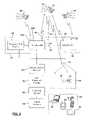
- FIG. 1is an overall system view of a collection and communication system in the continental United States.
- FIG. 2is a system view at the regional level of the collection and communication system.
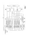
- FIG. 3is a detailed block diagrammatic view of a local collection facility illustrated in FIGS. 1 and 2 .
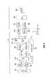
- FIG. 4is a detailed block diagrammatic view of a remote uplink facility.
- FIG. 5is a block diagrammatic view of a monitoring system of FIG. 3 .
- FIG. 6Ais a plan view of a local collection receiver monitoring display.
- FIG. 6Bis a plan view of an uplink monitoring display.
- FIG. 6Cis a plan view of a thread monitoring display.
- FIG. 7is a flowchart of a method for operating a local collection facility and remote collection facility.
- FIG. 8is a flowchart illustrating a method for controlling a back-up receiver decoder circuit module at the local collection facility from a remote facility.
- module, circuit and/or devicerefers to an Application Specific Integrated Circuit (ASIC), an electronic circuit, a processor (shared, dedicated, or group) and memory that execute one or more software or firmware programs, a combinational logic circuit, and/or other suitable components that provide the described functionality.
- ASICApplication Specific Integrated Circuit
- processorshared, dedicated, or group
- memorythat execute one or more software or firmware programs, a combinational logic circuit, and/or other suitable components that provide the described functionality.
- the phrase at least one of A, B, and Cshould be construed to mean a logical (A or B or C), using a non-exclusive logical or. It should be understood that steps within a method may be executed in different order without altering the principles of the present disclosure.
- the present disclosureis described with respect to a satellite television system. However, the present disclosure may have various uses including satellite data transmission and reception for home or business uses.
- the systemmay also be used in a cable system or wireless terrestrial communication system.
- a collection and communication system 10includes a satellite 12 that includes at least one transponder 13 .
- a satellite 12that includes at least one transponder 13 .
- multiple transpondersare in a satellite. Although only one satellite is shown, more than one is possible or even likely.
- the collection and communication system 10includes a central facility or Network operations center (NOC) 14 and a plurality of regional or remote uplink facilities (RUF) 16 A, 16 B, 16 C, 16 D, 16 E and 16 F.
- NOCNetwork operations center
- REFregional or remote uplink facilities
- the regional or remote uplink facilities 16 A- 16 Fmay be located at various locations throughout a landmass 18 such as the continental United States, including more or less than those illustrated.
- the regional or remote uplink facilities 16 A- 16 Fuplink various uplink signals 17 to satellite 12 .
- the satellitesdownlink signals 19 to various users 20 that may be located in different areas of the landmass 18 .
- the users 20may be mobile or fixed users.
- the uplink signals 17may be digital signals such as digital television signals or digital data signals.
- the digital television signalsmay be high definition television signals, standard definition signals or combinations of both. Uplinking may be performed at various frequencies including Ka band. The present disclosure, however, is not limited to Ka band. However, Ka band is a suitable frequency example used throughout this disclosure.
- the central facility or NOC 14may also receive downlink signals 19 corresponding to the uplink signals 17 from the various regional or remote uplink facilities and from itself for monitoring purposes. The central facility 14 may monitor and control the quality of all the signals broadcast from the system 10 .
- the central facility 14may also be coupled to the regional or remote uplink facilities through a network such as a computer network having associated communication lines 24 A- 24 F.
- Each communication line 24 A-Fis associated with a respective regional or remote uplink site 16 .
- Communication lines 24 A- 24 Fare terrestrial-based lines.
- all of the functions performed at the regional or remote uplink facilitiesmay be controlled centrally at the central facility 14 as long as the associated communication line 24 A-F is not interrupted.
- each regional or remote uplink site 16 A-Fmay operate autonomously so that uplink signals may continually be provided to the satellite 12 .
- Each of the regional or remote uplink and central facilitiesincludes a transmitting and receiving antenna which is not shown for simplicity in FIG. 1 .
- Each of the regional or remote uplink facilities 16 A- 16 Fmay also be in communication with a local collection facility collectively referred to with reference numeral 30 .
- a local collection facilitycollectively referred to with reference numeral 30 .
- three local collection facilitiesare associated with each remote uplink facility 16 .
- remote uplink facility 16 Ahas local collection facilities 30 A, 30 B and 30 C associated therewith.
- Local collection facilities 30 D- 30 Sare associated with one of the other remote uplink facilities 16 B- 16 F.
- the number of local collection facilities 30may be numerous, such as 40 for each remote uplink facility.
- the number of local collection facilities 30is limited by the amount of equipment and the capabilities thereof associated with each remote uplink facility 16 .
- the local collection facilities 30are used for collecting local television stations in various designated marketing areas (DMAs). As is illustrated, local collection facility 30 A is located in DMA 1 and local collection facility 30 B is located in DMA 2 . For simplicity, only two DMAs are illustrated. However, each local collection facility may be located in a DMA.
- DMAdesignated marketing areas
- the local collection facilities 30may be in communication with each remote uplink facility 16 through a communication network 32 .
- the communication network 32may be an Internet protocol (IP) network.
- IPInternet protocol
- the signals from the local collection facilities 30may thus be video-over-IP signals.
- Each of the remote uplink facilities 16are in communication with each local collection facility 30 through the communication network 32 .
- local collection facility 30 Ais in communication with the remote uplink facility 16 A through communication network 32 A
- local collection facility 30 Bis in communication with the remote uplink facility 16 A through communication network 32 B, and so on.
- the regional or remote uplink facilities 16 A- 16 F of FIG. 1are illustrated collectively as reference numeral 16 .
- the regional facilities 16may actually comprise two facilities that include a primary site 40 (such as the remote uplink facility 16 above) and a diverse site 42 .
- the primary site 40may be referred to as a primary broadcast center (PBC).
- the central site 14may also include a primary site and diverse site as is set forth herein.
- the primary site 40 and diverse site 42 of both the central and regional sitesmay be separated by at least 25 miles, or, more even more such as, at least 40 miles. In one constructed embodiment, 50 miles was used.
- the primary site 40includes a first antenna 44 for transmitting and receiving signals to and from satellite 12 .
- Diverse site 42also includes an antenna 46 for transmitting and receiving signals from satellite 12 .
- Primary site 40 and diverse site 42may also receive signals from GPS satellites 50 .
- GPS satellites 50generate signals corresponding to the location and a precision timed signal that may be provided to the primary site 40 through an antenna 52 and to the diverse site 42 through an antenna 54 .
- redundant GPS antennas ( 52 A,B) for each sitemay be provided.
- antennas 44 and 46may also be used to receive GPS signals.
- a precision time source 56may also be coupled to the primary site 40 and to the diverse site 42 for providing a precision time source.
- the precision time source 56may include various sources such as coupling to a central atomic clock.
- the precision time source 56may be used to trigger certain events such as advertising insertions and the like.
- the primary site 40 and the diverse site 42may be coupled through a communication line 60 .
- Communication line 60may be a dedicated communication line.
- the primary site 40 and the diverse site 42may communicate over the communication line using a video-over-Internet protocol (IP).
- IPvideo-over-Internet protocol
- Various signal sources 64such as an optical fiber line, copper line or antennas may provide incoming signals 66 to the local collection facility 30 .
- Incoming signal 66may be television signals.
- the television signalsmay be over-the-air high-definition signals, over-the-air standard television signals, or high or standard definition signals received through a terrestrial communication line.
- the incoming signals 66such as the television signals may be routed from the local collection facility 30 through the communication network 30 to the primary site 40 , or the diverse site 42 in the event of a switchover.
- the switchovermay be manual or a weather-related automatic switchover.
- a manual switchoverfor example, may be used during a maintenance condition.
- Users 20receive downlink signals 70 corresponding to the television signals.
- Users 20may include home-based systems, business-based systems or multiple dwelling unit systems.
- a user 20has a receiving antenna 72 coupled to an integrated receiver decoder (IRD) 74 that processes the signals and generates audio and video signals corresponding to the received downlink signal 70 for display on the television or monitor 76 .
- IRDintegrated receiver decoder
- satellite radio receiving systemsmay also be used in place of the IRD 74 .
- the integrated receiver decoder 74may be incorporated into or may be referred to as a set top box.
- the user 20may also be a mobile user.
- the user 20may therefore be implemented in a mobile device or portable device 80 .
- the portable device 80may include but are not limited to various types of devices such as a laptop computer 82 , a personal digital assistant 84 , a cellular telephone 86 or a portable media player 88 .
- the local collection facility 30is illustrated in more detail adjacent to the remote uplink facility (RUF) 16 .
- REFremote uplink facility
- Several remote facilitiesmay be directed to one remote uplink facility.
- Several remote uplink facilitiesmay be located across the country.
- the local collection facility 30is in communication with the remote uplink facility 16 through a network 32 such as an IP network.
- the local collection facility 30is used for collecting signals in a designated marketing area or other area.
- the channel signalsmay be received as over-the-air television signals or through a direct local feed such as an optical fiber or wire.
- an antenna or plurality of antennas 100are provided for an over-the-air signal.
- the antenna channel signalsare directed a plurality of primary receiver circuit modules 104 A-E (collectively referred to as 104 ).
- the number of receiver circuit modules 104depends upon various design parameters such as how many channels the designated market includes. Various numbers of receiver circuit modules 104 may be provided.
- back-up receiver circuit modules 106 A-Emay also receive the channel signals.
- a monitor receiver module 108may be included at the local collection facility 30 .
- the receiver circuit modules generally 104 , 106 and 108include a tuner module 110 and a demodulator module 112 .
- the receiver circuit module 104is used to tune and demodulate the over-the-air signals.
- the tuner 110may be fixed-tuned to a particular channel or may be adjustable.
- the receiver circuit modules 104 A-Eare suitable for fixed tuning.
- the monitor receiver circuit module 108is particularly suited for multi-channel tuning.
- the receiver circuit modules 104 , 106may be an Advanced Television Systems Committee (ATSC) receiver or a National Television System Committee (NTSC) receiver.
- ATSCAdvanced Television Systems Committee
- NTSCNational Television System Committee
- the receiverreceives the ATSC signal and demodulates it into an MPEG2 signal suitable for distribution over an Internet Protocol (IP) connection and thus may be referred to as an IP signal.
- IPInternet Protocol
- the monitor receiver module 108may be in communication with an antenna switch 114 .
- the antenna switch 114is in communication with the antennas 100 .
- the antenna switch 114may be used to communicate the output of a particular antenna to the monitor receiver decoder 108 .
- An asynchronous serial interface (ASI) router 120may also be provided. This is an optional component.
- the serial interface router 120may be a high definition serial digital interface router.
- the router 120may receive local feeds 118 directly from the local channel providers. The feeds may also be in MPEG2 format. These may be provided through a wire or optical fiber.
- the router 120routes the channel signals received from the local feeds 118 to the receiver circuit monitor receiver module 108 where received signals are decoded.
- the local collection facility 30may also include a monitoring integrated receiver decoder (MIRD) 140 .
- the output of the monitoring IRD 140may be provided to an MIRD encoder 142 .
- the IRD 140may also be referred to as a set top box.
- the monitoring IRD 140receives downlinked satellite signals and converts these signals to a decoded signal (HD SDI, for example).
- the MIRD encoder 142encodes the signals in a format such as IP format or MPEG 2 format.
- the output of the monitor IRD encoder 142 and the primary receivermay be communicated to a primary IP switch 146 .
- the output of the monitor IRD encoder 142 and the back-up receiver modules 106may be communicated to a back-up IP switch 148 .
- Both IP switches 146 , 148route IP signals such as the MPEG2 signals through the IP network 32 .
- Each of the outputs of the primary receiver modules 104 , back-up receiver modules 106 , the monitoring IRD 140 and the monitoring receiver 108may be a monitoring source for the monitoring system 230 described below in FIG. 4 .
- the monitoring systemmay be used to monitor and control the primary receivers 104 , the back-up receivers 106 , the antenna switch 114 , the monitoring IRD 140 and the monitoring receiver 106 .
- the proper receiver outputis routed through the proper switch and is used as the on-air signal. Switching between primary receivers and back-up receivers will be described below.
- the IP signals received from the primary switch 146 and the back-up IP switch 148are routed to a primary ATSC decoder 200 and a back-up ATSC decoder 202 .
- the decoders 200 , 202may decode the ATSC signals MPEG2 signals into an ASI or other serial digital interface signal. It should be noted that, although only one is shown, a separate primary ATSC decoder 200 may be provided for each of the receiver circuit modules 104 in each of the local collection facilities 30 .
- the decoders 200 , 202may also be referred to as MPEG decoders.
- the decodersmay be MPEG2 decoders.
- each primary receiver 104may correspond to a primary decoder 200 and a back-up decoder 202 .
- the output of each decoder 200 , 202is in communication with a receive transfer unit 204 .
- the receive transfer unit 204may be a high definition receive transfer unit.
- the receive transfer unit 204acts as a switch to switch between the primary decoder 200 and the back-up decoder 202 . Switching may be commanded at the monitoring system.
- One output of the receiver transfer unit 204may be in communication with a primary encoder 206 .
- a group of channelsmay share a back-up encoder 208 .
- the router 210is used to route the output of the RTU 204 to the back-up encoder 208 .
- the RTU output from a plurality of different channelsmay be provided as an input to the router 210 so that one of the outputs may be selected for the back-up encoder 208 .
- the output of the primary encoder 206 and the back-up encoder 208are provided to a primary multiplexer 212 and a back-up multiplexer 214 .
- the output from a plurality of primary encoders for a plurality of different channelsmay be provided to the primary multiplexer and the back-up multiplexer 212 , 214 .
- the encoders 206 , 208may provide the multiplexers signals from various remote local collection facilities.
- the multiplexers 212 , 214are used to generate a multiplexed signal that is communicated to a respective primary advanced transport processing system (ATPS) 218 and a back-up advanced transport processing system (ATPS) 220 .
- the advanced transport processing systems 218 , 220convert the multiplexed signals into an advanced transport stream such as a DIRECTV® A3 transport stream.
- the ATPSs 218 , 220may act as an encryption module for inserting encryption into the transport stream.
- a primary modulator 222 and a back-up modulator 224receive the transport stream from the respective primary ATPS 218 or the back-up ATPS 220 .
- the primary modulator 222 and the back-up modulator 224modulate the transport stream and generate an RF signal at a frequency such as an L-band frequency.
- An RF switch 226may be referred to as an intermediate frequency (IF) switch 226 .
- the RF switchprovides one output signal to the uplink RF system 228 .
- the uplink signalmay then be communicated to the satellite 12 of FIG. 1 . Should the system not be a satellite system, the signal may be communicated terrestrially through a distribution system in a wired or wireless manner.
- Several circuits 210 - 226may be included in a remote facility 16 , each one corresponding to one transponder on the satellite.
- a monitoring system 230may be in communication with and monitor and control the decoder 200 , 202 , the RTU 204 , the router 210 the encoders 206 , 208 and the multiplexers 212 , 214 for communicating with the various local collection facilities.
- the monitoring system 230may be in communication with the primary ATPS 218 , the back-up ATPS 220 , the primary modulator 222 and the back-up modulator 224 .
- the monitoring system 230may be referred to as an advanced broadcast monitoring system 230 .
- multiple local collection facilities 30may be coupled to a remote collection facility 16 .
- the diverse uplink facility or diverse site 42 illustrated in FIG. 4may include a primary and back-up ATPS, a modulator and RF switch.
- the monitoring system 230may control the signals to the diverse site 42 .
- a remote uplink facility monitor router 310is used to provide signals to the monitor network encoders 312 which in turn provide signals to a monitor feed network 314 .
- the L-band routersmay also provide signals to a demodulator 316 .
- the output of the demodulator 316 and the monitor network encoders 312may be provided to the monitor feed network 314 .
- the monitor feed network 314may be various types of transmission means used to communicate between the remote uplink facilities 16 and the network operation center 14 .
- the remote uplink facility 16may generate monitoring display 350 as well.
- the monitoring displays 350may also be used to control the various functions at the local collection facilities.
- the monitoring displaysmay be in communication with the monitor router 310 .
- the network operation center 14may also include multiple workstations 340 as well as a large monitor wall 338 .
- the workstations 340may have access to various control surfaces that can configure the monitor walls 338 as well as signals fed to the various monitors at the station.
- Control of the on-air failure recovery devices as well as the monitoring functions for every LCF and RUFare accomplished through control surfaces such as touch screens and keyboards together with a GUI at the workstations 340 in the network operation center 14 .
- the control surfacesmay be application-specific and present the status and control options for various multiple configurations for the application.
- the quality assurance (QA) room 342may not have any control functions therein.
- the monitors 350may be coupled to the monitor network encoders 315 for displaying various views from the remote uplink facility and the local collection facilities.
- the decoders 332may be MPEG decoders since the signal may be in MPEG form when received from the remote uplink facility.
- a local collection facility monitoris generated having four local collection facility channels 410 , 412 , 414 , and 416 .
- Each displaymay also include an under-monitor display 418 used to identify the particular channel signal.
- the under-monitor displays 418may display the actual channel number, the station identification or other information and the like.
- an uplink monitoris illustrated having an uplink channel one 420 , an uplink channel two 422 , an uplink channel three 424 , and an uplink channel four 426 .
- An under-monitor display 428may also be included with each of the displays 420 - 426 .
- the uplink channelsreceive the uplink channel signals so that they may be monitored.
- the uplink channel signalsprovide an indication as to the uplink channel.
- Various selectionsmay be made for the particular uplink channels for the particular remote uplink facilities.
- FIG. 6Cincludes an uplink channel signal 440 and a local collection facility IRD signal 442 .
- the local collection facility IRD signal 442may be received through the monitoring IRD located at the local collection facility. This is illustrated in FIG. 3 as reference numeral 140 .
- the displaymay also display a channel from the local collection facility, the back-up receiver channel or the local collection facility monitor receiver. Both displays 440 and 442 may include an under-monitor display 450 .
- FIGS. 3 , 4 and. 7a method of operating the system illustrated in FIGS. 3 and 4 is illustrated.
- the remote facility 16may ultimately include a plurality of decoders and encoders for each channel and a back-up encoder that is shared by several channels.
- the encoder outputsmay be multiplexed together.
- Step 510generates primary receiver signals and back-up receiver signals at a local collection facility or a plurality of local collection facilities.
- the primary receiver signals and the back-up receiver signalsmay be received through a tuner that is tuned to the channel signal received through the antenna 100 or through a direct cable connection 118 .
- the signalmay be demodulated in the demodulator 112 .
- the demodulated signalsmay be MPEG2 signals that are also IP signals capable of transmission through the IP backhaul 32 .
- the receiver signalsare communicated to the IP switches 146 , 148 .
- the primary receiversprovide signals to the primary IP switch 146 .
- the back-up receivers 106communicate signals through the back-up IP switch 148 .
- the IP signalsuch as the MPEG2 signals, is communicated through the IP backhaul to a primary decoder 200 or a back-up decoder 202 .
- Each decodermay correspond to a single one of the receivers.
- the back-up decodersmay correspond to one of the back-up receivers.
- the decodersmay be assigned to the multicast group assigned to the corresponding receiver. This may be controlled by the monitoring system.
- decoded IP signalsare formed at the decoder. Both the primary and back-up decoder form decoded signals.
- the decoded signalsare provided to the RTU 204 or switch.
- the RTUmay be controlled to select one of the inputs of the primary decoder 200 or the back-up decoder 202 as its output signal.
- the output signal of the switchis provided to the primary encoder 206 and to a router 210 .
- the router 210may be coupled a plurality of RTU outputs so that the back-up encoder 208 may be used for a plurality of different channel signals. In this example, a 16 ⁇ 1 router is used to potentially route one of 16 signals to the back-up encoder 208 upon a failure.
- step 518the encoders are encoded into an MPEG4 format or other type Of format.
- the encoded signalsare then provided to the multiplexers 212 , 214 .
- a plurality of encoded signals from various channelsis multiplexed together in step 520 .
- a transport streamis formed in the primary advanced transport processing system and the back-up advanced transport processing system.
- the transport signalsare modulated in the primary modulator 222 and the back-up modulator 224 for the respective primary and back-up transport processing systems.
- the modulatormodulates the signal in step 524 .
- the IF switchswitches between the primary stream or the back-up stream. If errors occur, as determined by the monitoring system 230 , one stream or the other stream may be chosen.
- uplink signalsare formed in an uplink RF system in response to the output of the switch 226 .
- the modulated signalsare communicated through an RF uplink system to a satellite 228 .
- the systemmay also be used for non-satellite systems and thus the uplink RF system may provide input to a cable network or an over-the-air system.
- the channel to controlis chosen at the control location.
- This channelwill be referred to as a first channel or identified channel.
- the control locationmay be the network operation center or the remote uplink facility 16 .
- the channelmay be automatically identified by the monitoring system 230 .
- step 612the primary and back-up multicast group source address in the local collection facility corresponding to the channel identified in step 610 is identified.
- the multicast groupmay be formed using Internet Group Management Protocol (IGMP) version 3.
- IGMPInternet Group Management Protocol
- step 614the RTU or switch 204 is identified for the channel in step 610 .
- the state of the RTUis also determined. That is, which output the RTU is providing is determined.
- step 616the on-air decoder is identified based on the switch state of the RTU.
- step 618the on-air multicast group for the decoder is identified.
- step 620an alternate multicast decoder address in step 618 is determined. This corresponds to the other decoder such as the back-up decoder if the primary is used or the primary decoder if the back-up is used.
- a thread decoder in the monitoring systemis set-up to monitor the identified channel.
- the thread decoder of the monitoring consoleis commanded to leave its current multicast group and join the multicast address for the identified channel.
- the various decoders and routersare set to route the signals to the screen display associated with the console.
- step 624the thread decoders are tuned according to the thread decoders for the monitoring system are tuned according to the station identification.
- the monitoring systemis used to view the alternate receiver such as the back-up receiver that may be used for the channel.
- step 628other channels are blocked from using the alternate receiver.
- step 630if the signals through the alternate receiver are acceptable or not acceptable, then step 632 ends. This may be performed by the operator determining that the signals are not acceptable or automatically by the operator not responding within a certain amount of time from displaying the alternate channel.
- step 634the process for switching to a back-up channel begins.
- step 636the primary and back-up decoders are commanded to leave the current multicast group for the channel.
- step 638the primary and back-up decoder are commanded to join the new multicast group corresponding to the back-up receiver.
- step 640a verification signal verifying the joining may be generated and communicated to the monitoring system.
- the monitoring decodersmay be identified and commanded to leave the multicast group currently joined.
- the monitoring decodersmay be tuned to the program identification for the local channel source for the selected monitoring system.
- the alternate receiverwhich is now on the air, should be visible in the local collection facility display in the thread monitor (e.g. 442 of FIG. 6C ).
- the thread decodermay leave the current multicast group and place the still-on-air signal such as the primary signal back to the monitoring system.
Landscapes
- Engineering & Computer Science (AREA)
- Signal Processing (AREA)
- Multimedia (AREA)
- Physics & Mathematics (AREA)
- Astronomy & Astrophysics (AREA)
- General Physics & Mathematics (AREA)
- Databases & Information Systems (AREA)
- Two-Way Televisions, Distribution Of Moving Picture Or The Like (AREA)
Abstract
Description
Claims (25)
Priority Applications (1)
| Application Number | Priority Date | Filing Date | Title |
|---|---|---|---|
| US11/929,373US9049354B2 (en) | 2007-10-30 | 2007-10-30 | Method and system for monitoring and controlling a back-up receiver in local collection facility from a remote facility using an IP network |
Applications Claiming Priority (1)
| Application Number | Priority Date | Filing Date | Title |
|---|---|---|---|
| US11/929,373US9049354B2 (en) | 2007-10-30 | 2007-10-30 | Method and system for monitoring and controlling a back-up receiver in local collection facility from a remote facility using an IP network |
Publications (2)
| Publication Number | Publication Date |
|---|---|
| US20090110052A1 US20090110052A1 (en) | 2009-04-30 |
| US9049354B2true US9049354B2 (en) | 2015-06-02 |
Family
ID=40582798
Family Applications (1)
| Application Number | Title | Priority Date | Filing Date |
|---|---|---|---|
| US11/929,373Active2031-01-04US9049354B2 (en) | 2007-10-30 | 2007-10-30 | Method and system for monitoring and controlling a back-up receiver in local collection facility from a remote facility using an IP network |
Country Status (1)
| Country | Link |
|---|---|
| US (1) | US9049354B2 (en) |
Cited By (1)
| Publication number | Priority date | Publication date | Assignee | Title |
|---|---|---|---|---|
| US10051338B2 (en) | 2015-10-21 | 2018-08-14 | At&T Intellectual Property I, L.P. | System and method for coordinating back-up services for land based content subscribers |
Families Citing this family (14)
| Publication number | Priority date | Publication date | Assignee | Title |
|---|---|---|---|---|
| US8072874B2 (en) | 2007-09-11 | 2011-12-06 | The Directv Group, Inc. | Method and system for switching to an engineering signal processing system from a production signal processing system |
| US8356321B2 (en)* | 2007-09-11 | 2013-01-15 | The Directv Group, Inc. | Method and system for monitoring and controlling receiving circuit modules at a local collection facility from a remote facility |
| US9313457B2 (en) | 2007-09-11 | 2016-04-12 | The Directv Group, Inc. | Method and system for monitoring a receiving circuit module and controlling switching to a back-up receiving circuit module at a local collection facility from a remote facility |
| US8973058B2 (en) | 2007-09-11 | 2015-03-03 | The Directv Group, Inc. | Method and system for monitoring and simultaneously displaying a plurality of signal channels in a communication system |
| US8170069B2 (en) | 2007-09-11 | 2012-05-01 | The Directv Group, Inc. | Method and system for processing signals from a local collection facility at a signal processing facility |
| US8479234B2 (en)* | 2007-09-12 | 2013-07-02 | The Directv Group, Inc. | Method and system for monitoring and controlling a local collection facility from a remote facility using an asynchronous transfer mode (ATM) network |
| US8988986B2 (en) | 2007-09-12 | 2015-03-24 | The Directv Group, Inc. | Method and system for controlling a back-up multiplexer in a local collection facility from a remote facility |
| US7861270B2 (en)* | 2007-09-12 | 2010-12-28 | The Directv Group, Inc. | Method and system for controlling a back-up receiver and encoder in a local collection facility from a remote facility |
| US9049354B2 (en)* | 2007-10-30 | 2015-06-02 | The Directv Group, Inc. | Method and system for monitoring and controlling a back-up receiver in local collection facility from a remote facility using an IP network |
| US9037074B2 (en)* | 2007-10-30 | 2015-05-19 | The Directv Group, Inc. | Method and system for monitoring and controlling a local collection facility from a remote facility through an IP network |
| US8077706B2 (en)* | 2007-10-31 | 2011-12-13 | The Directv Group, Inc. | Method and system for controlling redundancy of individual components of a remote facility system |
| US9049037B2 (en)* | 2007-10-31 | 2015-06-02 | The Directv Group, Inc. | Method and system for monitoring and encoding signals in a local facility and communicating the signals between a local collection facility and a remote facility using an IP network |
| US9762973B2 (en) | 2008-11-04 | 2017-09-12 | The Directv Group, Inc. | Method and system for operating a receiving circuit module to encode a channel signal into multiple encoding formats |
| US9831971B1 (en) | 2011-04-05 | 2017-11-28 | The Directv Group, Inc. | Method and system for operating a communication system encoded into multiple independently communicated encoding formats |
Citations (170)
| Publication number | Priority date | Publication date | Assignee | Title |
|---|---|---|---|---|
| US4317010A (en) | 1978-12-22 | 1982-02-23 | Fillot Jean Jacques Y | Remote monitoring system for remote locating and gain regulating of amplification circuits in data transmission line |
| US4984252A (en) | 1987-11-10 | 1991-01-08 | Nec Corporation | Channel switching system |
| US5189516A (en) | 1990-04-23 | 1993-02-23 | The Grass Valley Group, Inc. | Video preview system for allowing multiple outputs to be viewed simultaneously on the same monitor |
| US5257106A (en) | 1990-08-28 | 1993-10-26 | Sony Corporation | Television signal receiver with memory for storing data on different television system |
| US5323322A (en) | 1992-03-05 | 1994-06-21 | Trimble Navigation Limited | Networked differential GPS system |
| US5327421A (en) | 1992-11-06 | 1994-07-05 | At&T Bell Laboratories | Apparatus for interfacing between telecommunications call signals and broadband signals |
| US5351130A (en) | 1993-01-28 | 1994-09-27 | Houston Satellite Systems, Inc. | Satellite receiver with improved memory back-up and loading capabilities |
| US5452297A (en) | 1993-12-20 | 1995-09-19 | At&T Corp. | Access switches for large ATM networks |
| US5463656A (en) | 1993-10-29 | 1995-10-31 | Harris Corporation | System for conducting video communications over satellite communication link with aircraft having physically compact, effectively conformal, phased array antenna |
| US5499046A (en) | 1994-05-23 | 1996-03-12 | Cable Services Technologies, Inc. | CATV distribution system with each channel having its own remote scheduler |
| US5513180A (en) | 1991-05-14 | 1996-04-30 | Fujitsu Limited | Television signal and ATM cell switching system |
| US5524113A (en) | 1993-08-30 | 1996-06-04 | Washington University | ATM switch interface |
| US5566353A (en) | 1994-09-06 | 1996-10-15 | Bylon Company Limited | Point of purchase video distribution system |
| US5583562A (en) | 1993-12-03 | 1996-12-10 | Scientific-Atlanta, Inc. | System and method for transmitting a plurality of digital services including imaging services |
| US5600573A (en)* | 1992-12-09 | 1997-02-04 | Discovery Communications, Inc. | Operations center with video storage for a television program packaging and delivery system |
| US5640673A (en) | 1988-06-17 | 1997-06-17 | Fujitsu Limited | Broadcasting satellite communication system with improved answer signal transmission |
| US5646675A (en) | 1989-06-22 | 1997-07-08 | Airtrax | System and method for monitoring video program material |
| US5659350A (en) | 1992-12-09 | 1997-08-19 | Discovery Communications, Inc. | Operations center for a television program packaging and delivery system |
| US5666487A (en) | 1995-06-28 | 1997-09-09 | Bell Atlantic Network Services, Inc. | Network providing signals of different formats to a user by multplexing compressed broadband data with data of a different format into MPEG encoded data stream |
| US5666293A (en) | 1994-05-27 | 1997-09-09 | Bell Atlantic Network Services, Inc. | Downloading operating system software through a broadcast channel |
| US5684714A (en) | 1995-05-08 | 1997-11-04 | Kabushiki Kaisha Toshiba | Method and system for a user to manually alter the quality of a previously encoded video sequence |
| US5708961A (en) | 1995-05-01 | 1998-01-13 | Bell Atlantic Network Services, Inc. | Wireless on-premises video distribution using digital multiplexing |
| US5793413A (en) | 1995-05-01 | 1998-08-11 | Bell Atlantic Network Services, Inc. | Wireless video distribution |
| US5926230A (en) | 1995-02-06 | 1999-07-20 | Sony Corporation | Electrical program guide system and method |
| US5930251A (en) | 1996-02-01 | 1999-07-27 | Mitsubishi Denki Kabushiki Kaisha | Multimedia information processing system |
| US5933123A (en) | 1997-12-03 | 1999-08-03 | Kaul-Tronics, Inc. | Combined satellite and terrestrial antenna |
| US5949766A (en) | 1996-12-30 | 1999-09-07 | Motorola, Inc. | Ground device for communicating with an elevated communication hub and method of operation thereof |
| US5999518A (en) | 1996-12-04 | 1999-12-07 | Alcatel Usa Sourcing, L.P. | Distributed telecommunications switching system and method |
| US6047162A (en) | 1997-09-25 | 2000-04-04 | Com Dev Limited | Regional programming in a direct broadcast satellite |
| US6154772A (en) | 1997-11-04 | 2000-11-28 | Georgia Tech Research Corporation | System and method for the delivery of digital video and data over a communication channel |
| US20010003846A1 (en)* | 1999-05-19 | 2001-06-14 | New Horizons Telecasting, Inc. | Encapsulated, streaming media automation and distribution system |
| US6272137B1 (en) | 1997-03-21 | 2001-08-07 | Oki Electric Industry Co., Ltd. | ATM transmission system with subsystems interconnected through reduced number of signal lines |
| US20010026537A1 (en)* | 2000-02-24 | 2001-10-04 | Michael Massey | Satellite internet backbone network system using virtual onboard switching |
| US6308286B1 (en) | 1994-06-30 | 2001-10-23 | Hughes Electronics Corporation | Complexity reduction system and method for integrated redundancy switchover systems |
| US20010036198A1 (en) | 1996-09-05 | 2001-11-01 | Hughes Electronics Corporation | Dynamic mapping of broadcast resources |
| US20020007494A1 (en) | 1998-09-28 | 2002-01-17 | Hodge Winston W. | Interactive digital program material encoder and system |
| US6373817B1 (en) | 1999-12-30 | 2002-04-16 | At&T Corp. | Chase me system |
| US20020053049A1 (en) | 1997-12-30 | 2002-05-02 | Shoji Shiomoto | Error correction encoding method and apparatus data transmission method receiving method and receiver |
| US20020061023A1 (en) | 1997-05-30 | 2002-05-23 | Masaaki Takizawa | ATM communication terminal and ATM communication system |
| US6401242B1 (en) | 1997-10-24 | 2002-06-04 | General Instrument Corporation | Method and apparatus for designating a preferred source to avoid duplicative programming services |
| US6400720B1 (en) | 1999-06-21 | 2002-06-04 | General Instrument Corporation | Method for transporting variable length and fixed length packets in a standard digital transmission frame |
| US20020105976A1 (en)* | 2000-03-10 | 2002-08-08 | Frank Kelly | Method and apparatus for deriving uplink timing from asynchronous traffic across multiple transport streams |
| US20020150061A1 (en) | 1998-08-07 | 2002-10-17 | Hughes Electronics Corporation | Method and apparatus for performing satellite selection in a broadcast communication system |
| US6490273B1 (en) | 1998-08-05 | 2002-12-03 | Sprint Communications Company L.P. | Asynchronous transfer mode architecture migration |
| US20020186320A1 (en) | 2001-06-06 | 2002-12-12 | Carlsgaard Eric Stephen | Video signal processing system with auxiliary information processing capability |
| US20020194596A1 (en) | 2001-06-18 | 2002-12-19 | Srivastava Gopal K. | Control of multiple AV-devices by a single master controller using infrared transmitted commands and bus transmitted commands |
| US20030007564A1 (en) | 2000-06-09 | 2003-01-09 | Cha-Gyun Jeong | Method and devices for digital video signal compression and multi-screen process by multi-thread scaling |
| US6510163B1 (en) | 1997-07-25 | 2003-01-21 | Samsung Electronics Co., Ltd. | Network interface for interfacing PDH network and ATM network |
| US20030018975A1 (en) | 2001-07-18 | 2003-01-23 | Stone Christopher J. | Method and system for wireless audio and video monitoring |
| US20030028897A1 (en) | 2001-08-06 | 2003-02-06 | Brooks Paul D. | Technique for reverse transport of data in a hybrid fiber coax cable system |
| US6529146B1 (en) | 2000-06-09 | 2003-03-04 | Interactive Video Technologies, Inc. | System and method for simultaneously encoding data in multiple formats and at different bit rates |
| US6557031B1 (en) | 1997-09-05 | 2003-04-29 | Hitachi, Ltd. | Transport protocol conversion method and protocol conversion equipment |
| US20030088873A1 (en) | 1997-01-07 | 2003-05-08 | United Video Properties, Inc. | System and method for distributing and broadcasting multimedia |
| US20030095554A1 (en) | 2001-11-21 | 2003-05-22 | Nec Corporation | Network transfer system and transfer method |
| WO2003058967A1 (en) | 2001-12-28 | 2003-07-17 | Pegasus Development Corporation | Wideband direct-to-home broadcasting satellite communications system and method |
| US20030140353A1 (en) | 1999-11-08 | 2003-07-24 | Qwest Communications International Inc. | Digital headend and full service network for distribution video and audio programming |
| US20030161262A1 (en) | 2002-02-26 | 2003-08-28 | Nec Corporation | High speed switching router using APS and method for switching the same |
| US6625811B1 (en) | 1997-04-25 | 2003-09-23 | Sony Corporation | Multichannel broadcasting system |
| US20030196211A1 (en) | 2002-04-10 | 2003-10-16 | Peter Chan | Systems, methods and apparatuses for simulated rapid tuning of digital video channels |
| US6654923B1 (en) | 1999-09-09 | 2003-11-25 | Nortel Networks Limited | ATM group protection switching method and apparatus |
| US20040001478A1 (en) | 2002-06-27 | 2004-01-01 | Broadcom Corporation | System and method for isolating network clients |
| US20040022535A1 (en)* | 2002-08-01 | 2004-02-05 | Steve Wang | System and method for preventing signal loss in an optical communications network |
| US20040022275A1 (en) | 2002-08-02 | 2004-02-05 | Blanchard Scott D. | Methods and apparatus for coupling an earth terminal to a satellite |
| US6724760B2 (en) | 1997-08-06 | 2004-04-20 | Fujitsu Limited | ATM switch |
| US6724774B1 (en) | 1998-05-18 | 2004-04-20 | Nec Corporation | Subscriber access apparatus capable of adapting all of analog communication access network, ISDN access network and XDSL access network to ATM core network |
| US20040078807A1 (en) | 2002-06-27 | 2004-04-22 | Fries Robert M. | Aggregated EPG manager |
| US6741553B1 (en) | 1999-12-08 | 2004-05-25 | Nortel Networks Limited | Method and system for protecting virtual traffic in a communications network |
| US6751214B1 (en) | 2000-03-30 | 2004-06-15 | Azanda Network Devices, Inc. | Methods and apparatus for dynamically allocating bandwidth between ATM cells and packets |
| US20040117831A1 (en) | 1999-06-28 | 2004-06-17 | United Video Properties, Inc. | Interactive television program guide system and method with niche hubs |
| US20040120349A1 (en) | 2002-11-14 | 2004-06-24 | Hughes Electronics | Systems and methods for transmitting internet protocol data via satellite |
| US6782550B1 (en) | 2000-06-16 | 2004-08-24 | Minerva Networks, Inc. | Program guide with a current-time bar |
| US20040181813A1 (en) | 2003-02-13 | 2004-09-16 | Takaaki Ota | Methods and systems for rapid channel change within a digital system |
| US6795506B1 (en) | 1999-10-05 | 2004-09-21 | Cisco Technology, Inc. | Methods and apparatus for efficient scheduling and multiplexing |
| US6796555B1 (en) | 1999-07-19 | 2004-09-28 | Lucent Technologies Inc. | Centralized video controller for controlling distribution of video signals |
| US20040216171A1 (en) | 2001-08-16 | 2004-10-28 | Goldpocket Interactive | Remote monitoring system and method for interactive television data |
| US20040213247A1 (en) | 2000-09-11 | 2004-10-28 | Takashi Seki | Communication network system and method for synchronously controlling path connection |
| US20040234145A1 (en) | 2003-05-19 | 2004-11-25 | Hitachi, Ltd. | Encoding apparatus, video camera |
| US20040255333A1 (en) | 2001-06-06 | 2004-12-16 | Kevin Kenworthy | Centralized aggregation of broadcast television programming and multi-market digital delivery thereof over interconnected terrestrial fiber optic networks |
| US20050002339A1 (en) | 2003-06-20 | 2005-01-06 | Marconi Communications, Inc. | Distributed protection switching |
| US6873877B1 (en) | 1999-02-11 | 2005-03-29 | Loudeye Corp. | Distributed production system for digitally encoding information |
| US20050076134A1 (en) | 2001-05-17 | 2005-04-07 | Gil Bialik | Apparatus and method for multiple rich media formats video broadcasting |
| US20050086696A1 (en) | 1993-03-29 | 2005-04-21 | Microsoft Corporation | Methods for enabling near video-on-demand and video-on-request services using digital video recorders |
| US20050099969A1 (en) | 1998-04-03 | 2005-05-12 | Roberts Roswell Iii | Satellite receiver/router, system, and method of use |
| US6910078B1 (en) | 2001-11-15 | 2005-06-21 | Cisco Technology, Inc. | Methods and apparatus for controlling the transmission of stream data |
| US20050155079A1 (en) | 2004-01-13 | 2005-07-14 | Zhongming Chen | System and method for managing program assets |
| US20050160477A1 (en) | 2000-08-31 | 2005-07-21 | Kabushiki Kaisha Toshiba | Communication system using home gateway and access server for preventing attacks to home network |
| US20050175085A1 (en) | 2004-01-23 | 2005-08-11 | Sarnoff Corporation | Method and apparatus for providing dentable encoding and encapsulation |
| US20050210123A1 (en) | 2004-03-20 | 2005-09-22 | Hon Hai Precision Industry Co., Ltd. | System and method for graphically managing network devices |
| US20050210133A1 (en) | 2004-03-12 | 2005-09-22 | Danilo Florissi | Method and apparatus for determining monitoring locations in distributed systems |
| US20050240967A1 (en) | 2004-04-27 | 2005-10-27 | Anderson Glen J | System and method for improved channel surfing |
| US6963547B1 (en) | 1998-12-29 | 2005-11-08 | Lg Electronics Inc. | Local multipoint distribution system and ATM data communication method thereof |
| US20060018254A1 (en)* | 2004-07-26 | 2006-01-26 | John Sanders | Statistical multiplexer having protective features from extraneous messages generated by redundant system elements |
| US20060035610A1 (en) | 2004-08-13 | 2006-02-16 | Microsoft Corporation | Systems for unifying heterogeneous multimedia tuners |
| US20060050184A1 (en) | 2004-09-09 | 2006-03-09 | General Instrument Corporation | Hot/cold swappable consumer based tuner/demod/fec module |
| US20060064726A1 (en)* | 2004-09-21 | 2006-03-23 | Loner Patrick J | Method of using feedback from consumer terminals to adaptively control a satellite system |
| US20060085834A1 (en) | 2004-10-19 | 2006-04-20 | Cayin Technology Co., Ltd. | System and method for transmitting multi-channel signals |
| US7039116B1 (en) | 2000-11-07 | 2006-05-02 | Cisco Technology, Inc. | Methods and apparatus for embedding and format conversion of compressed video data |
| US7039937B1 (en) | 2001-02-28 | 2006-05-02 | Glenn R Bryce | System and method for providing satellite signals to multiple receiving units |
| US20060098735A1 (en) | 2004-11-10 | 2006-05-11 | Yu-Chung Chang | Apparatus for motion estimation using a two-dimensional processing element array and method therefor |
| US20060126634A1 (en) | 2004-10-06 | 2006-06-15 | Samsung Electronics Co., Ltd. | Method and apparatus of providing and receiving video services in digital audio broadcasting (DAB) system |
| US7072365B1 (en) | 2000-12-29 | 2006-07-04 | Arris Interactive, Llc | System and method for multiplexing broadband signals |
| US7080398B1 (en) | 1999-11-30 | 2006-07-18 | Agilent Technologies, Inc. | Monitoring system and method implementing warning interface logic |
| US20060166699A1 (en) | 2005-01-21 | 2006-07-27 | King's College London | Method of discovering multi-mode mobile terminals |
| US7088981B2 (en) | 2000-11-29 | 2006-08-08 | Broadcom Corporation | Apparatus for reducing flicker noise in a mixer circuit |
| US20060198389A1 (en) | 2005-03-01 | 2006-09-07 | Eriokson Michael J | Multi-drop ethernet |
| US20060242674A1 (en) | 2005-04-22 | 2006-10-26 | Medford Brad A | Methods and apparatus to broadcast advanced television system committee video in switched digital video systems |
| US7133377B1 (en) | 1999-05-24 | 2006-11-07 | Ico Services, Ltd. | Data multiplexing for diversity operation |
| US20070002851A1 (en) | 2005-06-30 | 2007-01-04 | Toni Paila | Transmission and reception of session packets |
| US20070022438A1 (en) | 2005-07-22 | 2007-01-25 | Marc Arseneau | System and Methods for Perfoming Online Purchase of Delivery of Service to a Handheld Device |
| US20070040933A1 (en) | 2005-07-22 | 2007-02-22 | Aircode Co., Ltd. | Transport stream reprocessing device and data broadcasting system using the device |
| US20070053379A1 (en) | 2005-09-06 | 2007-03-08 | Mark Hershey | Streaming media encoder with confidence monitor |
| US20070079351A1 (en) | 2000-12-11 | 2007-04-05 | Wang Jason N | System and method for balancing video encoding tasks between multiple processors |
| US20070094691A1 (en) | 2005-10-24 | 2007-04-26 | Gazdzinski Robert F | Method and apparatus for on-demand content transmission and control over networks |
| US20070091857A1 (en) | 2005-10-24 | 2007-04-26 | General Instrument Corporation | Method and apparatus for generating multiplexed signals |
| US7212738B1 (en) | 2002-08-01 | 2007-05-01 | Finisar Corporation | Preventing signal loss in an optical communications network |
| US7219367B2 (en) | 2002-09-09 | 2007-05-15 | Scientific-Atlanta, Inc. | Backup communication modes |
| US7224837B2 (en) | 2000-10-11 | 2007-05-29 | Screenpeaks Ltd. | Digital video broadcasting |
| US20070136765A1 (en) | 2005-12-13 | 2007-06-14 | The Directv Group, Inc. | Multiple dwelling unit satellite television delivery system |
| US20070136777A1 (en) | 2005-12-09 | 2007-06-14 | Charles Hasek | Caption data delivery apparatus and methods |
| US20070157281A1 (en) | 2005-12-23 | 2007-07-05 | United Video Properties, Inc. | Interactive media guidance system having multiple devices |
| US20070162927A1 (en) | 2004-07-23 | 2007-07-12 | Arun Ramaswamy | Methods and apparatus for monitoring the insertion of local media content into a program stream |
| US20070186251A1 (en) | 2006-02-03 | 2007-08-09 | Horowitz Edward D | Emergency satellite network |
| US7260369B2 (en) | 2005-08-03 | 2007-08-21 | Kamilo Feher | Location finder, tracker, communication and remote control system |
| US20070204300A1 (en) | 2006-02-27 | 2007-08-30 | Markley Jeffrey P | Methods and apparatus for selecting digital interface technology for programming and data delivery |
| US20070204311A1 (en) | 2006-02-27 | 2007-08-30 | Hasek Charles A | Methods and apparatus for selecting digital coding/decoding technology for programming and data delivery |
| US20070261073A1 (en)* | 2006-04-25 | 2007-11-08 | Xorbit, Inc. | System and method for monitoring video data |
| US20070263627A1 (en) | 2001-01-26 | 2007-11-15 | Nec Corporation | Method and system for controlling communication network and router used in the network |
| US20070268817A1 (en) | 2006-05-22 | 2007-11-22 | Nortel Networks Limited | Method and system for protecting a sub-domain within a broadcast domain |
| US7302224B2 (en) | 2000-05-03 | 2007-11-27 | The Directv Group, Inc. | Communication system for rebroadcasting electronic content within local area network |
| US20070291713A1 (en) | 2006-06-20 | 2007-12-20 | Fujitsu Limited | Communication system |
| US7315887B1 (en) | 2001-04-11 | 2008-01-01 | Alcatel Lucent | Facilitating integration of communications network equipment inventory management |
| US7333425B2 (en) | 2002-11-19 | 2008-02-19 | Alcatel | Failure localization in a transmission network |
| US20080066096A1 (en) | 2006-08-24 | 2008-03-13 | Sbc Knowledge Ventures L.P. | Method and apparatus for sending stored advertising data from an internet protocol television end user network interface device |
| US7346918B2 (en)* | 2000-12-27 | 2008-03-18 | Z-Band, Inc. | Intelligent device system and method for distribution of digital signals on a wideband signal distribution system |
| US20080069155A1 (en) | 2006-09-14 | 2008-03-20 | Tandberg Television Inc. | Systems and methods for analog channel reuse in a cable system |
| US20080101455A1 (en) | 2006-10-25 | 2008-05-01 | Digital Deck, Inc. | Apparatus and method for multiple format encoding |
| US20080102750A1 (en) | 2006-11-01 | 2008-05-01 | Keener David J | Broadcast method and system |
| US20080137543A1 (en) | 2006-12-12 | 2008-06-12 | Cisco Technology, Inc. | Remote testing of an electronic device via network connection |
| US20080201748A1 (en) | 2006-02-27 | 2008-08-21 | Hasek Charles A | Methods and apparatus for device capabilities discovery and utilization within a content-based network |
| US20080282011A1 (en) | 2007-05-09 | 2008-11-13 | Arcadyan Technology Corporation | Remote control system and method thereof |
| US20080291907A1 (en) | 2004-06-14 | 2008-11-27 | Siemens Aktiengesellschaft | Data-Transmission Device and Method for Transmitting Data with a Reduced Outage Risk |
| US7460832B2 (en) | 2004-04-12 | 2008-12-02 | The Directv Group, Inc. | Methods and apparatuses for minimizing co-channel interference |
| US20090025027A1 (en) | 2007-07-20 | 2009-01-22 | Michael Craner | Systems & methods for allocating bandwidth in switched digital video systems based on interest |
| US20090022241A1 (en) | 2005-01-21 | 2009-01-22 | Matsushita Electric Industrial Co., Ltd. | Wireless communication apparatus and wireless communication method |
| US7493648B2 (en) | 2000-04-11 | 2009-02-17 | Sony Corporation | Data transmission device, data receiving device, data transmitting method, data receiving method, recording device, playback device, recording method, and playback method |
| US20090052323A1 (en) | 2005-03-21 | 2009-02-26 | Dirk Breynaert | Managing Traffic in a Satellite Transmission System |
| US20090070830A1 (en)* | 2007-09-11 | 2009-03-12 | The Directv Group, Inc. | Method and System for Monitoring a Receiving Circuit Module and Controlling Switching to a Back-up Receiving Circuit Module at a Local Collection Facility from a Remote Facility |
| US20090067432A1 (en)* | 2007-09-12 | 2009-03-12 | The Directv Group, Inc. | Method and system for controlling a back-up multiplexer in a local collection facility from a remote facility |
| US20090070846A1 (en)* | 2007-09-12 | 2009-03-12 | The Directv Group, Inc. | Method and system for monitoring and controlling a local collection facility from a remote facility using an asynchronous transfer mode (atm) network |
| US20090066848A1 (en)* | 2007-09-12 | 2009-03-12 | The Directv Group, Inc. | Method and system for controlling a back-up receiver and encoder in a local collection facility from a remote facility |
| US20090067490A1 (en) | 2007-09-11 | 2009-03-12 | The Directv Group, Inc. | Method and system for monitoring and switching between a primary encoder and a back-up encoder in a communication system |
| US20090070825A1 (en)* | 2007-09-11 | 2009-03-12 | The Directv Group, Inc. | Method and System for Monitoring and Controlling Receiving Circuit Modules at a Local Collection Facility From a Remote Facility |
| US20090067365A1 (en) | 2007-09-11 | 2009-03-12 | The Directv Group, Inc. | Method and System for Switching to an Engineering Signal Processing System from a Production Signal Processing System |
| US20090070824A1 (en) | 2007-09-11 | 2009-03-12 | The Directv Group, Inc. | Method and System for Monitoring and Switching Between Primary and Back-up Uplink Signal Processing Circuits in a Satellite Communication System |
| US20090067433A1 (en)* | 2007-09-12 | 2009-03-12 | The Directv Group, Inc. | Method and system for controlling a back-up network adapter in a local collection facility from a remote facility |
| US20090069021A1 (en) | 2007-09-11 | 2009-03-12 | The Directv Group, Inc. | Method and System for Monitoring and Switching Between a First Uplink Signal Processing Circuit and a Second Uplink Signal Processing Circuit |
| US7525993B2 (en) | 2006-05-24 | 2009-04-28 | Newport Media, Inc. | Robust transmission system and method for mobile television applications |
| US20090110052A1 (en)* | 2007-10-30 | 2009-04-30 | Wasden Mitchell B | Method and system for monitoring and controlling a back-up receiver in local collection facility from a remote facility using an ip network |
| US20090109883A1 (en)* | 2007-10-31 | 2009-04-30 | Wasden Mitchell B | Method and system for monitoring and encoding signals in a local facility and communicating the signals between a local collection facility and a remote facility using an ip network |
| US20090113490A1 (en)* | 2007-10-30 | 2009-04-30 | Wasden Mitchell B | Method and system for monitoring and controlling a local collection facility from a remote facility through an ip network |
| US20090109836A1 (en)* | 2007-10-31 | 2009-04-30 | Wasden Mitchell B | Method and system for controlling redundancy of individual components of a remote facility system |
| US7529276B1 (en) | 2002-09-03 | 2009-05-05 | Cisco Technology, Inc. | Combined jitter and multiplexing systems and methods |
| US20090213814A1 (en) | 2003-08-20 | 2009-08-27 | Samsung Electronics Co., Ltd. | Method and apparatus for providing uplink packet data service in asynchronous wcdma system |
| US7596350B1 (en) | 2006-09-29 | 2009-09-29 | The Directv Group, Inc. | Method and system for determining delays between a primary site and diverse site in a satellite communication system |
| US7602846B1 (en) | 2003-08-01 | 2009-10-13 | Cisco Technology, Inc. | Efficiently distributing video using a hybrid network that uses existing infrastructure |
| US7607154B2 (en) | 2002-10-04 | 2009-10-20 | Rai Radiotelevisione Italiana S.P.A. | System for the transmission of DVB/MPEG digital signals, particularly for satellite communication |
| US7650620B2 (en) | 1998-03-06 | 2010-01-19 | Laurence A Fish | Method and apparatus for push and pull distribution of multimedia |
| US7746791B2 (en) | 2005-08-24 | 2010-06-29 | Abb Technology Ag | Monitoring an industrial communication network |
| US20100208595A1 (en) | 2007-10-09 | 2010-08-19 | Wei Zhao | Arrangement and a method for handling failures in a network |
| US8139517B2 (en) | 2005-10-14 | 2012-03-20 | Thomson Licensing | Method of generating and demultiplexing an optimized contribution signal, and regionalized data broadcasting system |
- 2007
- 2007-10-30USUS11/929,373patent/US9049354B2/enactiveActive
Patent Citations (176)
| Publication number | Priority date | Publication date | Assignee | Title |
|---|---|---|---|---|
| US4317010A (en) | 1978-12-22 | 1982-02-23 | Fillot Jean Jacques Y | Remote monitoring system for remote locating and gain regulating of amplification circuits in data transmission line |
| US4984252A (en) | 1987-11-10 | 1991-01-08 | Nec Corporation | Channel switching system |
| US5155483A (en) | 1987-11-10 | 1992-10-13 | Nec Corporation | Channel switching system |
| US5640673A (en) | 1988-06-17 | 1997-06-17 | Fujitsu Limited | Broadcasting satellite communication system with improved answer signal transmission |
| US5646675A (en) | 1989-06-22 | 1997-07-08 | Airtrax | System and method for monitoring video program material |
| US5189516A (en) | 1990-04-23 | 1993-02-23 | The Grass Valley Group, Inc. | Video preview system for allowing multiple outputs to be viewed simultaneously on the same monitor |
| US5257106A (en) | 1990-08-28 | 1993-10-26 | Sony Corporation | Television signal receiver with memory for storing data on different television system |
| US5513180A (en) | 1991-05-14 | 1996-04-30 | Fujitsu Limited | Television signal and ATM cell switching system |
| US5323322A (en) | 1992-03-05 | 1994-06-21 | Trimble Navigation Limited | Networked differential GPS system |
| US5327421A (en) | 1992-11-06 | 1994-07-05 | At&T Bell Laboratories | Apparatus for interfacing between telecommunications call signals and broadband signals |
| US20090254962A1 (en) | 1992-12-09 | 2009-10-08 | Comcast Ip Holdings I, Llc | Operations center for a television program packaging and delivery system |
| US5659350A (en) | 1992-12-09 | 1997-08-19 | Discovery Communications, Inc. | Operations center for a television program packaging and delivery system |
| US5600573A (en)* | 1992-12-09 | 1997-02-04 | Discovery Communications, Inc. | Operations center with video storage for a television program packaging and delivery system |
| US5351130A (en) | 1993-01-28 | 1994-09-27 | Houston Satellite Systems, Inc. | Satellite receiver with improved memory back-up and loading capabilities |
| US20050086696A1 (en) | 1993-03-29 | 2005-04-21 | Microsoft Corporation | Methods for enabling near video-on-demand and video-on-request services using digital video recorders |
| US5524113A (en) | 1993-08-30 | 1996-06-04 | Washington University | ATM switch interface |
| US5463656A (en) | 1993-10-29 | 1995-10-31 | Harris Corporation | System for conducting video communications over satellite communication link with aircraft having physically compact, effectively conformal, phased array antenna |
| US5583562A (en) | 1993-12-03 | 1996-12-10 | Scientific-Atlanta, Inc. | System and method for transmitting a plurality of digital services including imaging services |
| US5452297A (en) | 1993-12-20 | 1995-09-19 | At&T Corp. | Access switches for large ATM networks |
| US5499046A (en) | 1994-05-23 | 1996-03-12 | Cable Services Technologies, Inc. | CATV distribution system with each channel having its own remote scheduler |
| US5666293A (en) | 1994-05-27 | 1997-09-09 | Bell Atlantic Network Services, Inc. | Downloading operating system software through a broadcast channel |
| US6308286B1 (en) | 1994-06-30 | 2001-10-23 | Hughes Electronics Corporation | Complexity reduction system and method for integrated redundancy switchover systems |
| US5566353A (en) | 1994-09-06 | 1996-10-15 | Bylon Company Limited | Point of purchase video distribution system |
| US5926230A (en) | 1995-02-06 | 1999-07-20 | Sony Corporation | Electrical program guide system and method |
| US5793413A (en) | 1995-05-01 | 1998-08-11 | Bell Atlantic Network Services, Inc. | Wireless video distribution |
| US5708961A (en) | 1995-05-01 | 1998-01-13 | Bell Atlantic Network Services, Inc. | Wireless on-premises video distribution using digital multiplexing |
| US5684714A (en) | 1995-05-08 | 1997-11-04 | Kabushiki Kaisha Toshiba | Method and system for a user to manually alter the quality of a previously encoded video sequence |
| US5666487A (en) | 1995-06-28 | 1997-09-09 | Bell Atlantic Network Services, Inc. | Network providing signals of different formats to a user by multplexing compressed broadband data with data of a different format into MPEG encoded data stream |
| US5930251A (en) | 1996-02-01 | 1999-07-27 | Mitsubishi Denki Kabushiki Kaisha | Multimedia information processing system |
| US20010036198A1 (en) | 1996-09-05 | 2001-11-01 | Hughes Electronics Corporation | Dynamic mapping of broadcast resources |
| US5999518A (en) | 1996-12-04 | 1999-12-07 | Alcatel Usa Sourcing, L.P. | Distributed telecommunications switching system and method |
| US5949766A (en) | 1996-12-30 | 1999-09-07 | Motorola, Inc. | Ground device for communicating with an elevated communication hub and method of operation thereof |
| US20030088873A1 (en) | 1997-01-07 | 2003-05-08 | United Video Properties, Inc. | System and method for distributing and broadcasting multimedia |
| US6272137B1 (en) | 1997-03-21 | 2001-08-07 | Oki Electric Industry Co., Ltd. | ATM transmission system with subsystems interconnected through reduced number of signal lines |
| US6625811B1 (en) | 1997-04-25 | 2003-09-23 | Sony Corporation | Multichannel broadcasting system |
| US6496522B1 (en) | 1997-05-30 | 2002-12-17 | Hitachi, Ltd. | ATM communication terminal and ATM communication system |
| US20020061023A1 (en) | 1997-05-30 | 2002-05-23 | Masaaki Takizawa | ATM communication terminal and ATM communication system |
| US6510163B1 (en) | 1997-07-25 | 2003-01-21 | Samsung Electronics Co., Ltd. | Network interface for interfacing PDH network and ATM network |
| US6724760B2 (en) | 1997-08-06 | 2004-04-20 | Fujitsu Limited | ATM switch |
| US6557031B1 (en) | 1997-09-05 | 2003-04-29 | Hitachi, Ltd. | Transport protocol conversion method and protocol conversion equipment |
| US6047162A (en) | 1997-09-25 | 2000-04-04 | Com Dev Limited | Regional programming in a direct broadcast satellite |
| US6401242B1 (en) | 1997-10-24 | 2002-06-04 | General Instrument Corporation | Method and apparatus for designating a preferred source to avoid duplicative programming services |
| US6434562B1 (en) | 1997-11-04 | 2002-08-13 | Georgia Tech Research Corporation | Computer system and method for providing digital video and data over a communication channel |
| US6154772A (en) | 1997-11-04 | 2000-11-28 | Georgia Tech Research Corporation | System and method for the delivery of digital video and data over a communication channel |
| US5933123A (en) | 1997-12-03 | 1999-08-03 | Kaul-Tronics, Inc. | Combined satellite and terrestrial antenna |
| US20020053049A1 (en) | 1997-12-30 | 2002-05-02 | Shoji Shiomoto | Error correction encoding method and apparatus data transmission method receiving method and receiver |
| US7650620B2 (en) | 1998-03-06 | 2010-01-19 | Laurence A Fish | Method and apparatus for push and pull distribution of multimedia |
| US20050099969A1 (en) | 1998-04-03 | 2005-05-12 | Roberts Roswell Iii | Satellite receiver/router, system, and method of use |
| US6724774B1 (en) | 1998-05-18 | 2004-04-20 | Nec Corporation | Subscriber access apparatus capable of adapting all of analog communication access network, ISDN access network and XDSL access network to ATM core network |
| US6490273B1 (en) | 1998-08-05 | 2002-12-03 | Sprint Communications Company L.P. | Asynchronous transfer mode architecture migration |
| US20020150061A1 (en) | 1998-08-07 | 2002-10-17 | Hughes Electronics Corporation | Method and apparatus for performing satellite selection in a broadcast communication system |
| US20020007494A1 (en) | 1998-09-28 | 2002-01-17 | Hodge Winston W. | Interactive digital program material encoder and system |
| US6963547B1 (en) | 1998-12-29 | 2005-11-08 | Lg Electronics Inc. | Local multipoint distribution system and ATM data communication method thereof |
| US6873877B1 (en) | 1999-02-11 | 2005-03-29 | Loudeye Corp. | Distributed production system for digitally encoding information |
| US20010003846A1 (en)* | 1999-05-19 | 2001-06-14 | New Horizons Telecasting, Inc. | Encapsulated, streaming media automation and distribution system |
| US7133377B1 (en) | 1999-05-24 | 2006-11-07 | Ico Services, Ltd. | Data multiplexing for diversity operation |
| US6400720B1 (en) | 1999-06-21 | 2002-06-04 | General Instrument Corporation | Method for transporting variable length and fixed length packets in a standard digital transmission frame |
| US20040117831A1 (en) | 1999-06-28 | 2004-06-17 | United Video Properties, Inc. | Interactive television program guide system and method with niche hubs |
| US6796555B1 (en) | 1999-07-19 | 2004-09-28 | Lucent Technologies Inc. | Centralized video controller for controlling distribution of video signals |
| US6654923B1 (en) | 1999-09-09 | 2003-11-25 | Nortel Networks Limited | ATM group protection switching method and apparatus |
| US6795506B1 (en) | 1999-10-05 | 2004-09-21 | Cisco Technology, Inc. | Methods and apparatus for efficient scheduling and multiplexing |
| US20030140353A1 (en) | 1999-11-08 | 2003-07-24 | Qwest Communications International Inc. | Digital headend and full service network for distribution video and audio programming |
| US7080398B1 (en) | 1999-11-30 | 2006-07-18 | Agilent Technologies, Inc. | Monitoring system and method implementing warning interface logic |
| US6741553B1 (en) | 1999-12-08 | 2004-05-25 | Nortel Networks Limited | Method and system for protecting virtual traffic in a communications network |
| US6373817B1 (en) | 1999-12-30 | 2002-04-16 | At&T Corp. | Chase me system |
| US20010026537A1 (en)* | 2000-02-24 | 2001-10-04 | Michael Massey | Satellite internet backbone network system using virtual onboard switching |
| US20020105976A1 (en)* | 2000-03-10 | 2002-08-08 | Frank Kelly | Method and apparatus for deriving uplink timing from asynchronous traffic across multiple transport streams |
| US6751214B1 (en) | 2000-03-30 | 2004-06-15 | Azanda Network Devices, Inc. | Methods and apparatus for dynamically allocating bandwidth between ATM cells and packets |
| US7493648B2 (en) | 2000-04-11 | 2009-02-17 | Sony Corporation | Data transmission device, data receiving device, data transmitting method, data receiving method, recording device, playback device, recording method, and playback method |
| US7302224B2 (en) | 2000-05-03 | 2007-11-27 | The Directv Group, Inc. | Communication system for rebroadcasting electronic content within local area network |
| US20030007564A1 (en) | 2000-06-09 | 2003-01-09 | Cha-Gyun Jeong | Method and devices for digital video signal compression and multi-screen process by multi-thread scaling |
| US6529146B1 (en) | 2000-06-09 | 2003-03-04 | Interactive Video Technologies, Inc. | System and method for simultaneously encoding data in multiple formats and at different bit rates |
| US6782550B1 (en) | 2000-06-16 | 2004-08-24 | Minerva Networks, Inc. | Program guide with a current-time bar |
| US20050160477A1 (en) | 2000-08-31 | 2005-07-21 | Kabushiki Kaisha Toshiba | Communication system using home gateway and access server for preventing attacks to home network |
| US20040213247A1 (en) | 2000-09-11 | 2004-10-28 | Takashi Seki | Communication network system and method for synchronously controlling path connection |
| US7224837B2 (en) | 2000-10-11 | 2007-05-29 | Screenpeaks Ltd. | Digital video broadcasting |
| US7039116B1 (en) | 2000-11-07 | 2006-05-02 | Cisco Technology, Inc. | Methods and apparatus for embedding and format conversion of compressed video data |
| US7088981B2 (en) | 2000-11-29 | 2006-08-08 | Broadcom Corporation | Apparatus for reducing flicker noise in a mixer circuit |
| US20070079351A1 (en) | 2000-12-11 | 2007-04-05 | Wang Jason N | System and method for balancing video encoding tasks between multiple processors |
| US7346918B2 (en)* | 2000-12-27 | 2008-03-18 | Z-Band, Inc. | Intelligent device system and method for distribution of digital signals on a wideband signal distribution system |
| US7072365B1 (en) | 2000-12-29 | 2006-07-04 | Arris Interactive, Llc | System and method for multiplexing broadband signals |
| US20070263627A1 (en) | 2001-01-26 | 2007-11-15 | Nec Corporation | Method and system for controlling communication network and router used in the network |
| US7039937B1 (en) | 2001-02-28 | 2006-05-02 | Glenn R Bryce | System and method for providing satellite signals to multiple receiving units |
| US7315887B1 (en) | 2001-04-11 | 2008-01-01 | Alcatel Lucent | Facilitating integration of communications network equipment inventory management |
| US20050076134A1 (en) | 2001-05-17 | 2005-04-07 | Gil Bialik | Apparatus and method for multiple rich media formats video broadcasting |
| US20040255333A1 (en) | 2001-06-06 | 2004-12-16 | Kevin Kenworthy | Centralized aggregation of broadcast television programming and multi-market digital delivery thereof over interconnected terrestrial fiber optic networks |
| US20020186320A1 (en) | 2001-06-06 | 2002-12-12 | Carlsgaard Eric Stephen | Video signal processing system with auxiliary information processing capability |
| US20020194596A1 (en) | 2001-06-18 | 2002-12-19 | Srivastava Gopal K. | Control of multiple AV-devices by a single master controller using infrared transmitted commands and bus transmitted commands |
| US20030018975A1 (en) | 2001-07-18 | 2003-01-23 | Stone Christopher J. | Method and system for wireless audio and video monitoring |
| US20030028897A1 (en) | 2001-08-06 | 2003-02-06 | Brooks Paul D. | Technique for reverse transport of data in a hybrid fiber coax cable system |
| US20040216171A1 (en) | 2001-08-16 | 2004-10-28 | Goldpocket Interactive | Remote monitoring system and method for interactive television data |
| US6910078B1 (en) | 2001-11-15 | 2005-06-21 | Cisco Technology, Inc. | Methods and apparatus for controlling the transmission of stream data |
| US20030095554A1 (en) | 2001-11-21 | 2003-05-22 | Nec Corporation | Network transfer system and transfer method |
| US20030217362A1 (en)* | 2001-12-28 | 2003-11-20 | Summers Macy W. | Wideband direct-to-home broadcasting satellite communications system and method |
| WO2003058967A1 (en) | 2001-12-28 | 2003-07-17 | Pegasus Development Corporation | Wideband direct-to-home broadcasting satellite communications system and method |
| US20030161262A1 (en) | 2002-02-26 | 2003-08-28 | Nec Corporation | High speed switching router using APS and method for switching the same |
| US20030196211A1 (en) | 2002-04-10 | 2003-10-16 | Peter Chan | Systems, methods and apparatuses for simulated rapid tuning of digital video channels |
| US20040001478A1 (en) | 2002-06-27 | 2004-01-01 | Broadcom Corporation | System and method for isolating network clients |
| US20040078807A1 (en) | 2002-06-27 | 2004-04-22 | Fries Robert M. | Aggregated EPG manager |
| US20040022535A1 (en)* | 2002-08-01 | 2004-02-05 | Steve Wang | System and method for preventing signal loss in an optical communications network |
| US7212738B1 (en) | 2002-08-01 | 2007-05-01 | Finisar Corporation | Preventing signal loss in an optical communications network |
| US20040022275A1 (en) | 2002-08-02 | 2004-02-05 | Blanchard Scott D. | Methods and apparatus for coupling an earth terminal to a satellite |
| US7529276B1 (en) | 2002-09-03 | 2009-05-05 | Cisco Technology, Inc. | Combined jitter and multiplexing systems and methods |
| US7219367B2 (en) | 2002-09-09 | 2007-05-15 | Scientific-Atlanta, Inc. | Backup communication modes |
| US7607154B2 (en) | 2002-10-04 | 2009-10-20 | Rai Radiotelevisione Italiana S.P.A. | System for the transmission of DVB/MPEG digital signals, particularly for satellite communication |
| US20040120349A1 (en) | 2002-11-14 | 2004-06-24 | Hughes Electronics | Systems and methods for transmitting internet protocol data via satellite |
| US7333425B2 (en) | 2002-11-19 | 2008-02-19 | Alcatel | Failure localization in a transmission network |
| US20040181813A1 (en) | 2003-02-13 | 2004-09-16 | Takaaki Ota | Methods and systems for rapid channel change within a digital system |
| US20040234145A1 (en) | 2003-05-19 | 2004-11-25 | Hitachi, Ltd. | Encoding apparatus, video camera |
| US20050002339A1 (en) | 2003-06-20 | 2005-01-06 | Marconi Communications, Inc. | Distributed protection switching |
| US7602846B1 (en) | 2003-08-01 | 2009-10-13 | Cisco Technology, Inc. | Efficiently distributing video using a hybrid network that uses existing infrastructure |
| US20090213814A1 (en) | 2003-08-20 | 2009-08-27 | Samsung Electronics Co., Ltd. | Method and apparatus for providing uplink packet data service in asynchronous wcdma system |
| US20050155079A1 (en) | 2004-01-13 | 2005-07-14 | Zhongming Chen | System and method for managing program assets |
| US20050175085A1 (en) | 2004-01-23 | 2005-08-11 | Sarnoff Corporation | Method and apparatus for providing dentable encoding and encapsulation |
| US20050210133A1 (en) | 2004-03-12 | 2005-09-22 | Danilo Florissi | Method and apparatus for determining monitoring locations in distributed systems |
| US20050210123A1 (en) | 2004-03-20 | 2005-09-22 | Hon Hai Precision Industry Co., Ltd. | System and method for graphically managing network devices |
| US7460832B2 (en) | 2004-04-12 | 2008-12-02 | The Directv Group, Inc. | Methods and apparatuses for minimizing co-channel interference |
| US20050240967A1 (en) | 2004-04-27 | 2005-10-27 | Anderson Glen J | System and method for improved channel surfing |
| US20080291907A1 (en) | 2004-06-14 | 2008-11-27 | Siemens Aktiengesellschaft | Data-Transmission Device and Method for Transmitting Data with a Reduced Outage Risk |
| US20070162927A1 (en) | 2004-07-23 | 2007-07-12 | Arun Ramaswamy | Methods and apparatus for monitoring the insertion of local media content into a program stream |
| US20060018254A1 (en)* | 2004-07-26 | 2006-01-26 | John Sanders | Statistical multiplexer having protective features from extraneous messages generated by redundant system elements |
| US7380264B2 (en) | 2004-08-13 | 2008-05-27 | Microsoft Corporation | Systems for unifying heterogeneous multimedia tuners |
| US20060035610A1 (en) | 2004-08-13 | 2006-02-16 | Microsoft Corporation | Systems for unifying heterogeneous multimedia tuners |
| US20060050184A1 (en) | 2004-09-09 | 2006-03-09 | General Instrument Corporation | Hot/cold swappable consumer based tuner/demod/fec module |
| US20060064726A1 (en)* | 2004-09-21 | 2006-03-23 | Loner Patrick J | Method of using feedback from consumer terminals to adaptively control a satellite system |
| US20060126634A1 (en) | 2004-10-06 | 2006-06-15 | Samsung Electronics Co., Ltd. | Method and apparatus of providing and receiving video services in digital audio broadcasting (DAB) system |
| US20060085834A1 (en) | 2004-10-19 | 2006-04-20 | Cayin Technology Co., Ltd. | System and method for transmitting multi-channel signals |
| US20060098735A1 (en) | 2004-11-10 | 2006-05-11 | Yu-Chung Chang | Apparatus for motion estimation using a two-dimensional processing element array and method therefor |
| US20090022241A1 (en) | 2005-01-21 | 2009-01-22 | Matsushita Electric Industrial Co., Ltd. | Wireless communication apparatus and wireless communication method |
| US20060166699A1 (en) | 2005-01-21 | 2006-07-27 | King's College London | Method of discovering multi-mode mobile terminals |
| US20060198389A1 (en) | 2005-03-01 | 2006-09-07 | Eriokson Michael J | Multi-drop ethernet |
| US20090052323A1 (en) | 2005-03-21 | 2009-02-26 | Dirk Breynaert | Managing Traffic in a Satellite Transmission System |
| US20060242674A1 (en) | 2005-04-22 | 2006-10-26 | Medford Brad A | Methods and apparatus to broadcast advanced television system committee video in switched digital video systems |
| US20070002851A1 (en) | 2005-06-30 | 2007-01-04 | Toni Paila | Transmission and reception of session packets |
| US20070040933A1 (en) | 2005-07-22 | 2007-02-22 | Aircode Co., Ltd. | Transport stream reprocessing device and data broadcasting system using the device |
| US20070022438A1 (en) | 2005-07-22 | 2007-01-25 | Marc Arseneau | System and Methods for Perfoming Online Purchase of Delivery of Service to a Handheld Device |
| US7260369B2 (en) | 2005-08-03 | 2007-08-21 | Kamilo Feher | Location finder, tracker, communication and remote control system |
| US7746791B2 (en) | 2005-08-24 | 2010-06-29 | Abb Technology Ag | Monitoring an industrial communication network |
| US20070053379A1 (en) | 2005-09-06 | 2007-03-08 | Mark Hershey | Streaming media encoder with confidence monitor |
| US8139517B2 (en) | 2005-10-14 | 2012-03-20 | Thomson Licensing | Method of generating and demultiplexing an optimized contribution signal, and regionalized data broadcasting system |
| US20070094691A1 (en) | 2005-10-24 | 2007-04-26 | Gazdzinski Robert F | Method and apparatus for on-demand content transmission and control over networks |
| US20070091857A1 (en) | 2005-10-24 | 2007-04-26 | General Instrument Corporation | Method and apparatus for generating multiplexed signals |
| US20070136777A1 (en) | 2005-12-09 | 2007-06-14 | Charles Hasek | Caption data delivery apparatus and methods |
| US20070136765A1 (en) | 2005-12-13 | 2007-06-14 | The Directv Group, Inc. | Multiple dwelling unit satellite television delivery system |
| US20070157281A1 (en) | 2005-12-23 | 2007-07-05 | United Video Properties, Inc. | Interactive media guidance system having multiple devices |
| US20070186251A1 (en) | 2006-02-03 | 2007-08-09 | Horowitz Edward D | Emergency satellite network |
| US20080201748A1 (en) | 2006-02-27 | 2008-08-21 | Hasek Charles A | Methods and apparatus for device capabilities discovery and utilization within a content-based network |
| US20070204311A1 (en) | 2006-02-27 | 2007-08-30 | Hasek Charles A | Methods and apparatus for selecting digital coding/decoding technology for programming and data delivery |
| US20070204300A1 (en) | 2006-02-27 | 2007-08-30 | Markley Jeffrey P | Methods and apparatus for selecting digital interface technology for programming and data delivery |
| US20070261073A1 (en)* | 2006-04-25 | 2007-11-08 | Xorbit, Inc. | System and method for monitoring video data |
| US20070268817A1 (en) | 2006-05-22 | 2007-11-22 | Nortel Networks Limited | Method and system for protecting a sub-domain within a broadcast domain |
| US7525993B2 (en) | 2006-05-24 | 2009-04-28 | Newport Media, Inc. | Robust transmission system and method for mobile television applications |
| US20070291713A1 (en) | 2006-06-20 | 2007-12-20 | Fujitsu Limited | Communication system |
| US20080066096A1 (en) | 2006-08-24 | 2008-03-13 | Sbc Knowledge Ventures L.P. | Method and apparatus for sending stored advertising data from an internet protocol television end user network interface device |
| US20080069155A1 (en) | 2006-09-14 | 2008-03-20 | Tandberg Television Inc. | Systems and methods for analog channel reuse in a cable system |
| US7596350B1 (en) | 2006-09-29 | 2009-09-29 | The Directv Group, Inc. | Method and system for determining delays between a primary site and diverse site in a satellite communication system |
| US20080101455A1 (en) | 2006-10-25 | 2008-05-01 | Digital Deck, Inc. | Apparatus and method for multiple format encoding |
| US20080102750A1 (en) | 2006-11-01 | 2008-05-01 | Keener David J | Broadcast method and system |
| US20080137543A1 (en) | 2006-12-12 | 2008-06-12 | Cisco Technology, Inc. | Remote testing of an electronic device via network connection |
| US20080282011A1 (en) | 2007-05-09 | 2008-11-13 | Arcadyan Technology Corporation | Remote control system and method thereof |
| US20090025027A1 (en) | 2007-07-20 | 2009-01-22 | Michael Craner | Systems & methods for allocating bandwidth in switched digital video systems based on interest |
| US20090067490A1 (en) | 2007-09-11 | 2009-03-12 | The Directv Group, Inc. | Method and system for monitoring and switching between a primary encoder and a back-up encoder in a communication system |
| US20090070824A1 (en) | 2007-09-11 | 2009-03-12 | The Directv Group, Inc. | Method and System for Monitoring and Switching Between Primary and Back-up Uplink Signal Processing Circuits in a Satellite Communication System |
| US20090070830A1 (en)* | 2007-09-11 | 2009-03-12 | The Directv Group, Inc. | Method and System for Monitoring a Receiving Circuit Module and Controlling Switching to a Back-up Receiving Circuit Module at a Local Collection Facility from a Remote Facility |
| US20090070825A1 (en)* | 2007-09-11 | 2009-03-12 | The Directv Group, Inc. | Method and System for Monitoring and Controlling Receiving Circuit Modules at a Local Collection Facility From a Remote Facility |
| US20090067365A1 (en) | 2007-09-11 | 2009-03-12 | The Directv Group, Inc. | Method and System for Switching to an Engineering Signal Processing System from a Production Signal Processing System |
| US20090069021A1 (en) | 2007-09-11 | 2009-03-12 | The Directv Group, Inc. | Method and System for Monitoring and Switching Between a First Uplink Signal Processing Circuit and a Second Uplink Signal Processing Circuit |
| US20090066848A1 (en)* | 2007-09-12 | 2009-03-12 | The Directv Group, Inc. | Method and system for controlling a back-up receiver and encoder in a local collection facility from a remote facility |
| US20090067433A1 (en)* | 2007-09-12 | 2009-03-12 | The Directv Group, Inc. | Method and system for controlling a back-up network adapter in a local collection facility from a remote facility |
| US20090070846A1 (en)* | 2007-09-12 | 2009-03-12 | The Directv Group, Inc. | Method and system for monitoring and controlling a local collection facility from a remote facility using an asynchronous transfer mode (atm) network |
| US20090067432A1 (en)* | 2007-09-12 | 2009-03-12 | The Directv Group, Inc. | Method and system for controlling a back-up multiplexer in a local collection facility from a remote facility |
| US20100208595A1 (en) | 2007-10-09 | 2010-08-19 | Wei Zhao | Arrangement and a method for handling failures in a network |
| US20090113490A1 (en)* | 2007-10-30 | 2009-04-30 | Wasden Mitchell B | Method and system for monitoring and controlling a local collection facility from a remote facility through an ip network |
| US20090110052A1 (en)* | 2007-10-30 | 2009-04-30 | Wasden Mitchell B | Method and system for monitoring and controlling a back-up receiver in local collection facility from a remote facility using an ip network |
| US20090109836A1 (en)* | 2007-10-31 | 2009-04-30 | Wasden Mitchell B | Method and system for controlling redundancy of individual components of a remote facility system |
| US20090109883A1 (en)* | 2007-10-31 | 2009-04-30 | Wasden Mitchell B | Method and system for monitoring and encoding signals in a local facility and communicating the signals between a local collection facility and a remote facility using an ip network |
Non-Patent Citations (3)
| Title |
|---|
| "Specification for the use of Video and Audio Coding in DVB services delivered directly over IP protocols" DVB Document A084 Rev. 2, May 2007.* |
| "Specification for the Use of Video and Audio Coding in DVB Services Delivered Directly Over IP Protocols"; DVB Document Rev. 2; May 2007. |
| Non-final Office action dated Aug. 4, 2010 in U.S. Appl. No. 11/929,252, filed Oct. 30, 2007 by Mitchell B. Wasden et al. |
Cited By (2)
| Publication number | Priority date | Publication date | Assignee | Title |
|---|---|---|---|---|
| US10051338B2 (en) | 2015-10-21 | 2018-08-14 | At&T Intellectual Property I, L.P. | System and method for coordinating back-up services for land based content subscribers |
| US10390099B2 (en) | 2015-10-21 | 2019-08-20 | At&T Intellectual Property I, L.P. | System and method for coordinating back-up services for land based content subscribers |
Also Published As
| Publication number | Publication date |
|---|---|
| US20090110052A1 (en) | 2009-04-30 |
Similar Documents
| Publication | Publication Date | Title |
|---|---|---|
| US9037074B2 (en) | Method and system for monitoring and controlling a local collection facility from a remote facility through an IP network | |
| US9049354B2 (en) | Method and system for monitoring and controlling a back-up receiver in local collection facility from a remote facility using an IP network | |
| US8988986B2 (en) | Method and system for controlling a back-up multiplexer in a local collection facility from a remote facility | |
| US8479234B2 (en) | Method and system for monitoring and controlling a local collection facility from a remote facility using an asynchronous transfer mode (ATM) network | |
| US7861270B2 (en) | Method and system for controlling a back-up receiver and encoder in a local collection facility from a remote facility | |
| US8724635B2 (en) | Method and system for controlling a back-up network adapter in a local collection facility from a remote facility | |
| US8077706B2 (en) | Method and system for controlling redundancy of individual components of a remote facility system | |
| US9049037B2 (en) | Method and system for monitoring and encoding signals in a local facility and communicating the signals between a local collection facility and a remote facility using an IP network | |
| US8356321B2 (en) | Method and system for monitoring and controlling receiving circuit modules at a local collection facility from a remote facility | |
| US9313457B2 (en) | Method and system for monitoring a receiving circuit module and controlling switching to a back-up receiving circuit module at a local collection facility from a remote facility | |
| US8165060B2 (en) | Method and system for monitoring and switching between primary and back-up uplink signal processing circuits in a satellite communication system | |
| US8804499B2 (en) | Method and system for monitoring and switching between a first uplink signal processing circuit and a secondary uplink signal processing circuit | |
| US8072874B2 (en) | Method and system for switching to an engineering signal processing system from a production signal processing system | |
| US8792336B2 (en) | Method and system for monitoring and switching between primary and back-up receiver decoder circuits in a communication system | |
| US8424044B2 (en) | Method and system for monitoring and switching between a primary encoder and a back-up encoder in a communication system | |
| US9756290B2 (en) | Method and system for communicating between a local collection facility and a remote facility | |
| US8472871B2 (en) | Method and system for monitoring and switching between a primary and diverse site in a satellite communication system | |
| US8875190B2 (en) | Method and system for monitoring and displaying signals corresponding to a transponder of a satellite in a satellite communication system | |
| US9762973B2 (en) | Method and system for operating a receiving circuit module to encode a channel signal into multiple encoding formats | |
| US10349014B2 (en) | Method and system for monitoring and simultaneously displaying a plurality of signal channels in a communication system | |
| US8170069B2 (en) | Method and system for processing signals from a local collection facility at a signal processing facility | |
| US9300412B2 (en) | Method and system for operating a receiving circuit for multiple types of input channel signals | |
| US9831971B1 (en) | Method and system for operating a communication system encoded into multiple independently communicated encoding formats | |
| US20090070821A1 (en) | Method and system for operating a monitoring system for a satellite communication system | |
| US20090070829A1 (en) | Receiving circuit module for receiving and encoding channel signals and method for operating the same |
Legal Events
| Date | Code | Title | Description |
|---|---|---|---|
| AS | Assignment | Owner name:THE DIRECTV GROUP, INC., CALIFORNIA Free format text:ASSIGNMENT OF ASSIGNORS INTEREST;ASSIGNORS:WASDEN, MITCHELL B.;ARYA, VISHAL;MINER, DANIEL M.;AND OTHERS;SIGNING DATES FROM 20071015 TO 20071128;REEL/FRAME:020171/0359 Owner name:THE DIRECTV GROUP, INC., CALIFORNIA Free format text:ASSIGNMENT OF ASSIGNORS INTEREST;ASSIGNORS:WASDEN, MITCHELL B.;ARYA, VISHAL;MINER, DANIEL M.;AND OTHERS;REEL/FRAME:020171/0359;SIGNING DATES FROM 20071015 TO 20071128 | |
| STCF | Information on status: patent grant | Free format text:PATENTED CASE | |
| MAFP | Maintenance fee payment | Free format text:PAYMENT OF MAINTENANCE FEE, 4TH YEAR, LARGE ENTITY (ORIGINAL EVENT CODE: M1551); ENTITY STATUS OF PATENT OWNER: LARGE ENTITY Year of fee payment:4 | |
| AS | Assignment | Owner name:DIRECTV, LLC, CALIFORNIA Free format text:ASSIGNMENT OF ASSIGNORS INTEREST;ASSIGNOR:THE DIRECTV GROUP, INC.;REEL/FRAME:057018/0460 Effective date:20210728 | |
| AS | Assignment | Owner name:CREDIT SUISSE AG, CAYMAN ISLANDS BRANCH, AS COLLATERAL AGENT, NEW YORK Free format text:SECURITY AGREEMENT;ASSIGNOR:DIRECTV, LLC;REEL/FRAME:057695/0084 Effective date:20210802 | |
| AS | Assignment | Owner name:THE BANK OF NEW YORK MELLON TRUST COMPANY, N.A. AS COLLATERAL AGENT, TEXAS Free format text:SECURITY AGREEMENT;ASSIGNOR:DIRECTV, LLC;REEL/FRAME:058220/0531 Effective date:20210802 | |
| MAFP | Maintenance fee payment | Free format text:PAYMENT OF MAINTENANCE FEE, 8TH YEAR, LARGE ENTITY (ORIGINAL EVENT CODE: M1552); ENTITY STATUS OF PATENT OWNER: LARGE ENTITY Year of fee payment:8 | |
| AS | Assignment | Owner name:THE BANK OF NEW YORK MELLON TRUST COMPANY, N.A., AS COLLATERAL AGENT, TEXAS Free format text:SECURITY AGREEMENT;ASSIGNOR:DIRECTV, LLC;REEL/FRAME:066371/0690 Effective date:20240124 |