US9048812B2 - Bulk acoustic wave resonator comprising bridge formed within piezoelectric layer - Google Patents
Bulk acoustic wave resonator comprising bridge formed within piezoelectric layerDownload PDFInfo
- Publication number
- US9048812B2 US9048812B2US13/208,909US201113208909AUS9048812B2US 9048812 B2US9048812 B2US 9048812B2US 201113208909 AUS201113208909 AUS 201113208909AUS 9048812 B2US9048812 B2US 9048812B2
- Authority
- US
- United States
- Prior art keywords
- bridge
- piezoelectric layer
- electrode
- baw resonator
- resonator structure
- Prior art date
- Legal status (The legal status is an assumption and is not a legal conclusion. Google has not performed a legal analysis and makes no representation as to the accuracy of the status listed.)
- Active, expires
Links
- 239000000463materialSubstances0.000claimsabstractdescription82
- 239000000758substrateSubstances0.000claimsabstractdescription20
- 230000008878couplingEffects0.000claimsdescription27
- 238000010168coupling processMethods0.000claimsdescription27
- 238000005859coupling reactionMethods0.000claimsdescription27
- 239000010949copperSubstances0.000claimsdescription10
- 239000003989dielectric materialSubstances0.000claimsdescription10
- RYGMFSIKBFXOCR-UHFFFAOYSA-NCopperChemical compound[Cu]RYGMFSIKBFXOCR-UHFFFAOYSA-N0.000claimsdescription5
- ZOKXTWBITQBERF-UHFFFAOYSA-NMolybdenumChemical compound[Mo]ZOKXTWBITQBERF-UHFFFAOYSA-N0.000claimsdescription5
- 229910052802copperInorganic materials0.000claimsdescription5
- 229910052741iridiumInorganic materials0.000claimsdescription5
- GKOZUEZYRPOHIO-UHFFFAOYSA-Niridium atomChemical compound[Ir]GKOZUEZYRPOHIO-UHFFFAOYSA-N0.000claimsdescription5
- 229910052750molybdenumInorganic materials0.000claimsdescription5
- 239000011733molybdenumSubstances0.000claimsdescription5
- WFKWXMTUELFFGS-UHFFFAOYSA-NtungstenChemical compound[W]WFKWXMTUELFFGS-UHFFFAOYSA-N0.000claimsdescription5
- 229910052721tungstenInorganic materials0.000claimsdescription5
- 239000010937tungstenSubstances0.000claimsdescription5
- OKTJSMMVPCPJKN-UHFFFAOYSA-NCarbonChemical compound[C]OKTJSMMVPCPJKN-UHFFFAOYSA-N0.000claimsdescription4
- 229910052799carbonInorganic materials0.000claimsdescription4
- HBMJWWWQQXIZIP-UHFFFAOYSA-Nsilicon carbideChemical compound[Si+]#[C-]HBMJWWWQQXIZIP-UHFFFAOYSA-N0.000claimsdescription4
- VYPSYNLAJGMNEJ-UHFFFAOYSA-NSilicium dioxideChemical compoundO=[Si]=OVYPSYNLAJGMNEJ-UHFFFAOYSA-N0.000claimsdescription3
- 239000005388borosilicate glassSubstances0.000claimsdescription2
- 229910052751metalInorganic materials0.000claims4
- 239000002184metalSubstances0.000claims4
- 235000012239silicon dioxideNutrition0.000claims1
- 239000000377silicon dioxideSubstances0.000claims1
- 230000006872improvementEffects0.000description17
- 238000000059patterningMethods0.000description13
- 238000003780insertionMethods0.000description10
- 230000037431insertionEffects0.000description10
- 230000007423decreaseEffects0.000description9
- 238000000034methodMethods0.000description9
- 230000001902propagating effectEffects0.000description9
- 230000015572biosynthetic processEffects0.000description6
- 230000015556catabolic processEffects0.000description6
- 238000006731degradation reactionMethods0.000description6
- 239000007769metal materialSubstances0.000description6
- 239000005360phosphosilicate glassSubstances0.000description6
- XLOMVQKBTHCTTD-UHFFFAOYSA-NZinc monoxideChemical compound[Zn]=OXLOMVQKBTHCTTD-UHFFFAOYSA-N0.000description5
- 238000004519manufacturing processMethods0.000description5
- 230000009286beneficial effectEffects0.000description4
- 230000004048modificationEffects0.000description4
- 238000012986modificationMethods0.000description4
- 230000003466anti-cipated effectEffects0.000description3
- 230000000694effectsEffects0.000description3
- 238000002955isolationMethods0.000description3
- 238000012545processingMethods0.000description3
- 230000005641tunnelingEffects0.000description3
- 230000001413cellular effectEffects0.000description2
- 238000006243chemical reactionMethods0.000description2
- PMHQVHHXPFUNSP-UHFFFAOYSA-Mcopper(1+);methylsulfanylmethane;bromideChemical compoundBr[Cu].CSCPMHQVHHXPFUNSP-UHFFFAOYSA-M0.000description2
- 238000005516engineering processMethods0.000description2
- 230000005284excitationEffects0.000description2
- 239000010408filmSubstances0.000description2
- 230000007246mechanismEffects0.000description2
- 230000008569processEffects0.000description2
- 229910010271silicon carbideInorganic materials0.000description2
- 230000001629suppressionEffects0.000description2
- 238000010897surface acoustic wave methodMethods0.000description2
- 238000012360testing methodMethods0.000description2
- 239000011787zinc oxideSubstances0.000description2
- PIGFYZPCRLYGLF-UHFFFAOYSA-NAluminum nitrideChemical compound[Al]#NPIGFYZPCRLYGLF-UHFFFAOYSA-N0.000description1
- ZOXJGFHDIHLPTG-UHFFFAOYSA-NBoronChemical compound[B]ZOXJGFHDIHLPTG-UHFFFAOYSA-N0.000description1
- 230000009471actionEffects0.000description1
- 229910052782aluminiumInorganic materials0.000description1
- XAGFODPZIPBFFR-UHFFFAOYSA-NaluminiumChemical compound[Al]XAGFODPZIPBFFR-UHFFFAOYSA-N0.000description1
- 230000008901benefitEffects0.000description1
- 229910052796boronInorganic materials0.000description1
- 238000004891communicationMethods0.000description1
- 230000003247decreasing effectEffects0.000description1
- 230000002939deleterious effectEffects0.000description1
- 230000005684electric fieldEffects0.000description1
- 238000010348incorporationMethods0.000description1
- 238000007689inspectionMethods0.000description1
- 230000001788irregularEffects0.000description1
- 239000012528membraneSubstances0.000description1
- 230000000116mitigating effectEffects0.000description1
- 238000005457optimizationMethods0.000description1
- 229910021426porous siliconInorganic materials0.000description1
- 230000009467reductionEffects0.000description1
- 238000002310reflectometryMethods0.000description1
- 239000005368silicate glassSubstances0.000description1
- 229910052814silicon oxideInorganic materials0.000description1
- 239000010409thin filmSubstances0.000description1
- 238000012546transferMethods0.000description1
Images


Classifications
- H—ELECTRICITY
- H03—ELECTRONIC CIRCUITRY
- H03H—IMPEDANCE NETWORKS, e.g. RESONANT CIRCUITS; RESONATORS
- H03H9/00—Networks comprising electromechanical or electro-acoustic elements; Electromechanical resonators
- H03H9/15—Constructional features of resonators consisting of piezoelectric or electrostrictive material
- H03H9/17—Constructional features of resonators consisting of piezoelectric or electrostrictive material having a single resonator
- H—ELECTRICITY
- H03—ELECTRONIC CIRCUITRY
- H03H—IMPEDANCE NETWORKS, e.g. RESONANT CIRCUITS; RESONATORS
- H03H9/00—Networks comprising electromechanical or electro-acoustic elements; Electromechanical resonators
- H03H9/02—Details
- H03H9/125—Driving means, e.g. electrodes, coils
- H03H9/13—Driving means, e.g. electrodes, coils for networks consisting of piezoelectric or electrostrictive materials
- H03H9/132—Driving means, e.g. electrodes, coils for networks consisting of piezoelectric or electrostrictive materials characterized by a particular shape
- H—ELECTRICITY
- H03—ELECTRONIC CIRCUITRY
- H03H—IMPEDANCE NETWORKS, e.g. RESONANT CIRCUITS; RESONATORS
- H03H3/00—Apparatus or processes specially adapted for the manufacture of impedance networks, resonating circuits, resonators
- H03H3/007—Apparatus or processes specially adapted for the manufacture of impedance networks, resonating circuits, resonators for the manufacture of electromechanical resonators or networks
- H03H3/02—Apparatus or processes specially adapted for the manufacture of impedance networks, resonating circuits, resonators for the manufacture of electromechanical resonators or networks for the manufacture of piezoelectric or electrostrictive resonators or networks
- H03H3/04—Apparatus or processes specially adapted for the manufacture of impedance networks, resonating circuits, resonators for the manufacture of electromechanical resonators or networks for the manufacture of piezoelectric or electrostrictive resonators or networks for obtaining desired frequency or temperature coefficient
- H—ELECTRICITY
- H03—ELECTRONIC CIRCUITRY
- H03H—IMPEDANCE NETWORKS, e.g. RESONANT CIRCUITS; RESONATORS
- H03H9/00—Networks comprising electromechanical or electro-acoustic elements; Electromechanical resonators
- H03H9/02—Details
- H03H9/02007—Details of bulk acoustic wave devices
- H03H9/02086—Means for compensation or elimination of undesirable effects
- H03H9/02118—Means for compensation or elimination of undesirable effects of lateral leakage between adjacent resonators
- H—ELECTRICITY
- H03—ELECTRONIC CIRCUITRY
- H03H—IMPEDANCE NETWORKS, e.g. RESONANT CIRCUITS; RESONATORS
- H03H9/00—Networks comprising electromechanical or electro-acoustic elements; Electromechanical resonators
- H03H9/15—Constructional features of resonators consisting of piezoelectric or electrostrictive material
- H03H9/17—Constructional features of resonators consisting of piezoelectric or electrostrictive material having a single resonator
- H03H9/171—Constructional features of resonators consisting of piezoelectric or electrostrictive material having a single resonator implemented with thin-film techniques, i.e. of the film bulk acoustic resonator [FBAR] type
- H03H9/172—Means for mounting on a substrate, i.e. means constituting the material interface confining the waves to a volume
- H03H9/173—Air-gaps
- H—ELECTRICITY
- H03—ELECTRONIC CIRCUITRY
- H03H—IMPEDANCE NETWORKS, e.g. RESONANT CIRCUITS; RESONATORS
- H03H9/00—Networks comprising electromechanical or electro-acoustic elements; Electromechanical resonators
- H03H9/15—Constructional features of resonators consisting of piezoelectric or electrostrictive material
- H03H9/17—Constructional features of resonators consisting of piezoelectric or electrostrictive material having a single resonator
- H03H9/171—Constructional features of resonators consisting of piezoelectric or electrostrictive material having a single resonator implemented with thin-film techniques, i.e. of the film bulk acoustic resonator [FBAR] type
- H03H9/172—Means for mounting on a substrate, i.e. means constituting the material interface confining the waves to a volume
- H03H9/175—Acoustic mirrors
- H—ELECTRICITY
- H03—ELECTRONIC CIRCUITRY
- H03H—IMPEDANCE NETWORKS, e.g. RESONANT CIRCUITS; RESONATORS
- H03H9/00—Networks comprising electromechanical or electro-acoustic elements; Electromechanical resonators
- H03H9/46—Filters
- H03H9/54—Filters comprising resonators of piezoelectric or electrostrictive material
- H03H9/58—Multiple crystal filters
- H03H9/582—Multiple crystal filters implemented with thin-film techniques
- H03H9/583—Multiple crystal filters implemented with thin-film techniques comprising a plurality of piezoelectric layers acoustically coupled
- H03H9/584—Coupled Resonator Filters [CFR]
- H—ELECTRICITY
- H03—ELECTRONIC CIRCUITRY
- H03H—IMPEDANCE NETWORKS, e.g. RESONANT CIRCUITS; RESONATORS
- H03H9/00—Networks comprising electromechanical or electro-acoustic elements; Electromechanical resonators
- H03H9/46—Filters
- H03H9/54—Filters comprising resonators of piezoelectric or electrostrictive material
- H03H9/58—Multiple crystal filters
- H03H9/582—Multiple crystal filters implemented with thin-film techniques
- H03H9/583—Multiple crystal filters implemented with thin-film techniques comprising a plurality of piezoelectric layers acoustically coupled
- H03H9/585—Stacked Crystal Filters [SCF]
- H—ELECTRICITY
- H03—ELECTRONIC CIRCUITRY
- H03H—IMPEDANCE NETWORKS, e.g. RESONANT CIRCUITS; RESONATORS
- H03H9/00—Networks comprising electromechanical or electro-acoustic elements; Electromechanical resonators
- H03H9/46—Filters
- H03H9/54—Filters comprising resonators of piezoelectric or electrostrictive material
- H03H9/58—Multiple crystal filters
- H03H9/582—Multiple crystal filters implemented with thin-film techniques
- H03H9/586—Means for mounting to a substrate, i.e. means constituting the material interface confining the waves to a volume
- H03H9/587—Air-gaps
- H—ELECTRICITY
- H03—ELECTRONIC CIRCUITRY
- H03H—IMPEDANCE NETWORKS, e.g. RESONANT CIRCUITS; RESONATORS
- H03H9/00—Networks comprising electromechanical or electro-acoustic elements; Electromechanical resonators
- H03H9/46—Filters
- H03H9/54—Filters comprising resonators of piezoelectric or electrostrictive material
- H03H9/58—Multiple crystal filters
- H03H9/582—Multiple crystal filters implemented with thin-film techniques
- H03H9/586—Means for mounting to a substrate, i.e. means constituting the material interface confining the waves to a volume
- H03H9/589—Acoustic mirrors
- H—ELECTRICITY
- H03—ELECTRONIC CIRCUITRY
- H03H—IMPEDANCE NETWORKS, e.g. RESONANT CIRCUITS; RESONATORS
- H03H9/00—Networks comprising electromechanical or electro-acoustic elements; Electromechanical resonators
- H03H9/02—Details
- H03H9/02007—Details of bulk acoustic wave devices
Definitions
- Transducersgenerally convert electrical signals to mechanical signals or vibrations, and/or mechanical signals or vibrations to electrical signals. Acoustic transducers, in particular, convert electrical signals to acoustic waves and acoustic waves to electrical signal using inverse and direct piezo-electric effects. Acoustic transducers generally include acoustic resonators, such as thin film bulk acoustic resonators (FBARs), surface acoustic wave (SAW) resonators or bulk acoustic wave (BAW) resonators, and may be used in a wide variety of electronic applications, such as cellular telephones, personal digital assistants (PDAs), electronic gaming devices, laptop computers and other portable communications devices. For example, FBARs may be used for electrical filters and voltage transformers.
- FBARsmay be used for electrical filters and voltage transformers.
- an acoustic resonatorhas a layer of piezoelectric material between two conductive plates (electrodes), which may be formed on a thin membrane.
- FBAR devicesin particular, generate acoustic waves that can propagate in all possible lateral directions when stimulated by an applied time-varying electric field, as well as higher order harmonic mixing products. The laterally propagating modes and the higher order harmonic mixing products may have a deleterious impact on functionality.
- Filters based on FBAR technologyprovide a comparatively low in-band insertion loss due to the comparatively high quality factor (Q-factor) of FBAR devices.
- FBAR-based filtersare often employed in cellular or mobile telephones that can operate in multiple frequency bands.
- passbandthere may be one or more frequencies or frequency bands near the passband which contain signals at relatively high amplitudes that should be rejected by the filter.
- FBARstacked bulk acoustic resonator
- DBARdouble bulk acoustic resonator
- CRFcoupled resonator filter
- the DBARincludes two layers of piezoelectric materials between three electrodes in a single stack, forming a single resonant cavity. That is, a first layer of piezoelectric material is formed between a first (bottom) electrode and a second (middle) electrode, and a second layer of piezoelectric material is formed between the second (middle) electrode and a third (top) electrode.
- the DBAR deviceallows reduction of the area of a single bulk acoustic resonator device by about half.
- a CRFcomprises a coupling structure disposed between two vertically stacked FBARs.
- the CRFcombines the acoustic action of the two FBARs and provides a bandpass filter transfer function.
- the CRFhas two fundamental resonance modes, a symmetric mode and an anti-symmetric mode, of different frequencies.
- the degree of difference in the frequencies of the modesdepends, inter alia, on the degree or strength of the coupling between the two FBARs of the CRF.
- the passbandWhen the degree of coupling between the two FBARs is too great (over-coupled), the passband is unacceptably wide, and an unacceptable “swag” or “dip” in the center of the passband results, as does an attendant unacceptably high insertion loss in the center of the passband. When the degree of coupling between the FBARs is too low (under-coupled), the passband of the CRF is too narrow.
- All FBARs and filters based on FBARshave an active region.
- the active region of a CRFfor example, comprises the region of overlap of the top FBAR, the coupling structure, and the bottom FBAR.
- reflection of desired modescan result in mode conversion into spurious/undesired modes, and loss of acoustic energy over a desired frequency range (e.g., the passband of the CRF).
- FBAR devicesmitigation of acoustic losses at the boundaries and the resultant mode confinement in the active region of the FBAR (the region of overlap of the top electrode, the piezoelectric layer, and the bottom electrode) has been effected through various methods.
- framesare provided along one or more sides of the FBARs. The frames create an acoustic impedance mismatch that reduces losses by reflecting desired modes back to the active area of the resonator, thus improving the confinement of desired modes within the active region of the FBAR.
- FIG. 1Ashows a top-view of an FBAR in accordance with a representative embodiment.
- FIG. 1Bis a cross-sectional view of the FBAR of FIG. 1A , taken along the line 1 B- 1 B, having a bridge disposed within a piezoelectric layer, in accordance with a representative embodiment.
- FIG. 1Cis a cross-sectional view of an FBAR, having a bridge disposed within a piezoelectric layer, in accordance with another representative embodiment.
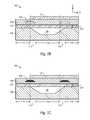
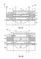
- FIGS. 2A-2Dare cross-sectional views of DBARs, each having bridges disposed within two piezoelectric layers of the DBAR, in accordance with a representative embodiment.
- FIGS. 3A-3Bare cross-sectional views of DBARs, each having a bridge disposed within a piezoelectric layer of the DBAR, in accordance with a representative embodiment.
- FIGS. 4A-4Bare cross-sectional views of DBARs, each having a bridge disposed within another piezoelectric layer of the DBAR, in accordance with a representative embodiment.
- FIGS. 5A-5Dare cross-sectional views of CRFs, each having bridges disposed within two piezoelectric layers of the CRF, in accordance with a representative embodiment.
- FIGS. 6A-6Bare cross-sectional views of CRFs, each having a bridge disposed within a piezoelectric layer of the CRF, in accordance with a representative embodiment.
- FIGS. 7A-7Bare cross-sectional views of CRFs, each having a bridge disposed within another piezoelectric layer of the CRF, in accordance with a representative embodiment.
- a deviceincludes one device and plural devices.
- the present teachingsrelate generally to BAW resonator structures comprising FBARs.
- the BAW resonator structuresprovide FBAR-based filters (e.g., ladder filters).
- FBAR-based filterse.g., ladder filters.
- Certain details of FBARs and/or BAW resonators and resonator filters, materials thereof and their methods of fabricationmay be found in one or more of the following commonly owned U.S. Patents and Patent Applications: U.S. Pat. No. 6,107,721 to Lakin; U.S. Pat. Nos. 5,587,620, 5,873,153, 6,507,983, 6,384,697, 7,275,292 and 7,629,865 to Ruby et al.; U.S. Pat. No.
- FIG. 1Ashows a top view of FBAR 100 in accordance with a representative embodiment.
- the FBAR 100includes a top electrode 101 (referred to below as second electrode 101 ) having five (5) sides, with a connection side 102 configured to provide an electrical connection to interconnect 103 .
- the interconnect 103provides electrical signals to the second electrode 101 to excite desired acoustic waves in a piezoelectric layer (not shown in FIG. 1A ) of the FBAR 100 .
- FIG. 1Bshows a cross-sectional view of the FBAR 100 taken along line 1 B- 1 B in accordance with a representative embodiment.
- the FBAR 100includes multiple layers stacked over substrate 105 having a cavity 106 .
- the inclusion of a cavity 106 for reflection of acoustic waves in the FBAR 100is merely illustrative.
- a known acoustic reflectore.g., a Bragg mirror (not shown)
- alternating layers of high and low acoustic impedancemay be provided in the substrate 105 to provide acoustic isolation in place of the cavity 106 , without departing from the scope of the present teachings.
- a first (bottom) electrode 107is disposed over the substrate 105 and partially over the cavity 106 (or Bragg mirror).
- a planarization layer 107 ′is also provided over the substrate as shown.
- the planarization layer 107 ′includes non-etchable borosilicate glass (NEBSG), for example.
- NBSGnon-etchable borosilicate glass
- planarization layer 107 ′does not need to be present in the structure (as it increases overall processing cost), but when present, it may improve quality of growth of subsequent layers and simplify their processing.
- a piezoelectric layer 108is disposed over the first electrode 107
- the second (top) electrode 101is disposed over the piezoelectric layer 108 .
- the structure provided by the first electrode 107 , the piezoelectric layer 108 and the second electrode 101is a bulk acoustic wave (BAW) resonator.
- BAWbulk acoustic wave
- the BAW resonatorWhen the BAW resonator is disposed over a cavity, it is a so-called FBAR (e.g., FBAR 100 ); and when the BAW resonator is disposed over an acoustic reflector (e.g., Bragg mirror), it is a so-called solidly mounted resonator (SMR).
- FBARe.g., FBAR 100
- SMRsolidly mounted resonator
- the present teachingscontemplate the use of either FBARs or SMRs in a variety of applications, including filters (e.g., ladder filters comprising a plurality of BAW resonators).
- a bridge 104is buried within the piezoelectric layer 108 , meaning that the bridge 104 is surrounded by the piezoelectric material of the piezoelectric layer 108 .
- the bridge 104is disposed along all sides of the FBAR 100 (i.e., along a perimeter of the FBAR 100 ).
- the bridge 104(and other bridges described in connection with representative embodiments below) has a trapezoidal cross-sectional shape. It is emphasized that the trapezoidal cross-sectional shape of the bridge of the representative embodiments is merely illustrative and the bridges are not limited to a trapezoidal cross-sectional shape.
- the cross-sectional shape of the bridges of the representative embodimentscould be square or rectangular, or of an irregular shape.
- the “slanting” walls of bridge 104are beneficial to the quality of layers (e.g., the quality of the crystalline piezoelectric layer(s)) grown over the bridge 104 (and other bridges described in connection with representative embodiments below).
- Typical dimensions of the bridge 104 (and other bridges described in connection with representative embodiments below)are approximately 2.0 ⁇ m to approximately 10.0 ⁇ m in width (x-dimension in the coordinate system shown in FIG. 1B ) and approximately 150 ⁇ to approximately 3000 ⁇ in height (y-dimension in the coordinate system shown in FIG. 1B ).
- the bridge 104extends over the cavity 106 (depicted as overlap 113 in FIG. 1B ).
- the overlap 113also referred to as the decoupling region
- the overlap 113has a width (x-dimension) of approximately 0.0 ⁇ m (i.e., no overlap with the cavity 106 ) to approximately 10.0 ⁇ m.
- optimum width of the bridge 104depends on the reflection of the eigen-modes at the boundary of an active region 114 (also referred to herein as an FBAR region) and a decoupling region (i.e., the overlap 113 ).
- the bridge 104is too wide, reliability issues can arise and can also limit the placement of similar FBARs (not shown) from being placed in proximity (thus unnecessarily increasing the total area of a chip).
- the propagating component of the complex evanescent wavecan be used to find the optimum width of the bridge 104 .
- the width of bridge 104is equal to an odd multiple of the quarter-wavelength of the complex evanescent wave, the reflectivity of the eigen-modes can be further increased, which can be manifested by parallel resistance Rp and Q-factor attaining maximum values.
- the width of the bridge 104can be modified in view of these other propogating modes. Such optimum width of the bridge 104 may be determined experimentally.
- the width and position of the bridge 104 (and other bridges described in connection with representative embodiments) and the amount of the overlap 113 with the cavity 106are selected to improve Q-factor enhancement of the resonant piston mode.
- the greater the overlap 113 of the bridge 104 with the cavity 106 of the FBAR 100the greater the improvement in the Q-factor, with the improvement realized being fairly small after an initial increase.
- the improvement in the Q-factormust be weighed against a decrease in the electromechanical effective coupling coefficient kt 2 , which decreases with increasing overlap 113 of the bridge 104 with the cavity 106 . Degradation of the coupling coefficient kt 2 results in a degradation of insertion loss (S 21 ) of a filter comprising FBARs.
- the overlap 113 of the bridge 104 with the cavity 106may be optimized experimentally.
- the bridge 104(and other bridges described in connection with representative embodiments below) has a height (y-dimension in the coordinate system of FIG. 1B ) of approximately 150 ⁇ to approximately 3000 ⁇ .
- the lower limit of the heightis determined by the limits of the process of releasing sacrificial material in the forming of the bridge 104 (and other bridges described in connection with representative embodiments below)
- the upper limit of the heightis determined by the quality of layers grown over the bridge 104 (and other bridges described in connection with representative embodiments) and by the quality of subsequent processing of possibly non-planar structures.
- the first electrode 107 and second electrode 101are formed of tungsten (W) having a thickness of approximately 1000 ⁇ to approximately 20000 ⁇ .
- Other materialsmay be used for the first electrode 107 and the second electrode 101 , including but not limited to molybdenum (Mo), iridium (Ir), copper (Cu), aluminum (Al) or a bi-metal material.
- the piezoelectric layer 108is formed of aluminum nitride (AlN) having a thickness of approximately 5000 ⁇ to approximately 25000 ⁇ .
- AlNaluminum nitride
- Other materialsmay be used for the piezoelectric layer 108 , including but not limited to zinc oxide (ZnO).
- the bridge 104growth of the piezoelectric layer 108 on the first electrode 107 is interrupted.
- the growth of the piezoelectric layer 108was interrupted at about half way through the anticipated thickness, resulting in formation the bridge 104 in approximately the middle of the completed piezoelectric layer 108 .
- This locationplaces the bridge 104 at about the point of maximum stress of the piezoelectric layer 108 , maximizing the energy decoupling effect of the bridge 104 .
- the bridge 104may be formed in different relative locations within the piezoelectric layer 108 without departing from the scope of the present teachings.
- the bridge 104may be formed by patterning a sacrificial material over the grown portion of the piezoelectric layer 108 , and then continuing growth of the remaining portion of the piezoelectric layer 108 thereover.
- the sacrificial materialis released leaving the bridge 104 “unfilled” (i.e., containing or filled with air).
- the sacrificial material used to form the bridge 104is the same as the sacrificial material used to form the cavity 106 , such as phosphosilicate glass (PSG), for example.
- PSGphosphosilicate glass
- the bridge 104defines a perimeter along the active region 114 of the FBAR 100 .
- the active region 114thus includes the portions of the acoustic resonator disposed over the cavity 106 and bounded by the perimeter provided by the bridge 104 .
- the active region of the FBAR 100is bordered around its perimeter by an acoustic impedance discontinuity created at least in part by the bridge 104 , and above and below (cavity 106 ) by an acoustic impedance discontinuity due to the presence of air.
- a resonant cavityis beneficially provided in the active region of the FBAR 100 .
- the bridge 104is unfilled (i.e., contains air), as is the cavity 106 .
- the bridge 104is “filled” (i.e., contains a dielectric or metal material having an acoustic impedance to provide the desired acoustic impedance discontinuity) to provide bridge 104 ′, described more fully below with reference to FIG. 1C .
- the bridge 104does not necessarily have to extend along all edges of the FBAR 100 , and therefore not along the perimeter of the FBAR 100 .
- the bridge 104may be provided on four “sides” of the five-sided FBAR 100 shown in FIG. 1A .
- the acoustic impedance mismatch provided by the bridge 104causes reflection of acoustic waves at the boundary that may otherwise propagate out of the active region and be lost, resulting in energy loss.
- the bridge 104serves to confine the modes of interest within the active region 114 of the FBAR 100 and to reduce energy losses in the FBAR 100 . Reducing such losses serves to increase the Q-factor of the FBAR 100 .
- the insertion loss (S 21 )is beneficially improved.
- the bridge 104has a width (x-dimension) of approximately 5.0 ⁇ m, a height of approximately 1500 ⁇ , and an overlap 113 of approximately 2.0 ⁇ m, that the piezoelectric layer 108 has a thickness (y-dimension) of approximately 10000 ⁇ , and that the bottom of the bridge 104 is approximately 5000 ⁇ above the bottom of the piezoelectric layer 108 , such that the bridge 104 is in about the middle of the piezoelectric layer 108 .
- Placement of the bridge 104 in about the middle of the piezoelectric layer 108increases parallel resistance Rp of the FBAR 100 from about 1.1 k ⁇ to about 3.5 k ⁇ , which is an increase of over 300 percent, e.g., at a frequency of operation of about 1.88 GHz. Since the bridge 104 is generally placed in a region of maximum stress, the impact of two competing phenomena is maximized: scattering at the leading edge of the bridge 104 (which generally leads to decrease of Q-factor) and decoupling of FBAR modes from the field region modes due to zeroing of normal stress at the upper and lower boundaries of the bridge 104 (which in general leads to increase of Q-factor).
- a third effectis related to poorer quality of piezoelectric material in the region grown immediately above the stop-growth plane. These three factors are weighed appropriately when determining placement of the bridge 104 within the piezoelectric layer 108 , and such optimization may be done experimentally, for example.
- FIG. 1Cshows a cross-sectional view of FBAR 100 in which the bridge is “filled” with a material having an acoustic impedance in order to provide significantly large lateral acoustic impedance discontinuity at the boundary between FBAR region 114 and decoupling region 113 .
- the mechanism of reducing losses in the filled bridge 104 ′relies on suppression and confinement of the propagating eigen-modes which are electrically excited in the FBAR region 114 as a part of piston mode excitation.
- Both ends of the filled bridge 104 ′provide mechanical discontinuities to control the phase of the reflected mode and to provide overall beneficial suppression of the propagating eigen-modes in the main FBAR region 114 .
- the main part of the piston modebecomes evanescent, that is, its amplitude decreases exponentially as it propagates towards the field region 115 . This decay process minimizes conversion of the piston mode into unwanted propagating modes at the impedance discontinuity regions created by the edges of the cavity 106 and the substrate 105 , thus leading to further beneficial increase of Q-factor.
- bridge 104 ′is filled with NEBSG, carbon doped oxide (CDO), silicon carbide (SiC) or other suitable dielectric material that will not release when the sacrificial material disposed in the cavity 106 is released.
- bridge 104 ′is filled with one of tungsten (W), molybdenum (Mo), copper (Cu), iridium (Ir) or other suitable metal materials that will not release when the sacrificial material disposed in the cavity 106 is released.
- the bridge 104 ′is fabricated by interrupting growth of the piezoelectric layer 108 on the first electrode 107 , for example, when the piezoelectric layer 108 is about half its desired thickness, resulting in formation the bridge 104 ′ in approximately the middle of the completed piezoelectric layer 108 .
- the NEBSG or other fill materialis formed by a known method.
- the FBAR 100is completed by continuing the growth of the remaining portion of the piezoelectric layer 108 , and forming the second electrode 101 of the FBAR 100 thereover.
- the bridge 104 ′remains filled with the selected, non-etchable material.
- Forming bridges within piezoelectric layer(s)may be implemented in other types of acoustic resonators, including DBARs and CRFs, resulting in similar improvements in parallel resistance Rp, Q-factors, and the like.
- FIGS. 2A-4Bshow cross-sectional views of DBARs 200 - 400 , respectively
- FIGS. 5A-7Bshow cross-sectional views of CRFs 500 - 700 , respectively, in accordance with representative embodiments.
- FIGS. 2A-2Dshow cross-sectional views of DBAR 200 in accordance with representative embodiments. It may be assumed for purposes of explanation that the top view of the DBAR 200 is substantially the same as the top view of the FBAR 100 , discussed above with reference to FIG. 1A . That is, the DBAR 200 may include a top electrode 101 (referred to below as third electrode 101 ), comprising five (5) sides, with a connection side 102 configured to provide the electrical connection to an interconnect 103 .
- third electrode 101referred to below as third electrode 101
- connection side 102configured to provide the electrical connection to an interconnect 103 .
- the DBAR 200comprises a plurality of layers disposed over a substrate 105 having a cavity 106 .
- the inclusion of a cavity 106 for reflection of acoustic waves in the DBAR 200is merely illustrative. It is emphasized that rather than cavity 106 , a known acoustic reflector (e.g., a Bragg mirror (not shown)) comprising alternating layers of high and low acoustic impedance may be provided in the substrate 105 to provide acoustic isolation.
- the plurality of layersincludes first (bottom) electrode 107 , first piezoelectric layer 108 , second (middle) electrode 111 , second piezoelectric layer 112 , and third (top) electrode 101 , discussed below.
- the first electrode 107is disposed over the substrate 105 and partially over the cavity 106 (or Bragg mirror).
- a planarization layer 107 ′is provided over the substrate as shown.
- the planarization layer 107 ′comprises NEBSG.
- the first piezoelectric layer 108is disposed over the first electrode 107 , and a first bridge 201 is included within the first piezoelectric layer 108 , meaning that the first bridge 201 is surrounded by the piezoelectric material of the first piezoelectric layer 108 , as discussed above with reference to bridge 104 .
- the first bridge 201is disposed along all sides (i.e., along the perimeter) of the DBAR 200 .
- the second electrode 111 and a planarization layer 109are disposed over the first piezoelectric layer 108 , where the planarization layer 109 generally does not overlap the cavity 106 .
- the planarization layer 109comprises NEBSG.
- the structure provided by the first electrode 107 , the first piezoelectric layer 108 and a second electrode 111is a BAW resonator, which in this illustrative embodiment comprises a first BAW resonator of the DBAR 200 .
- the BAW resonatorWhen the BAW resonator is disposed over a cavity, it is a so-called FBAR; and when the BAW resonator is disposed over an acoustic reflector (e.g., Bragg mirror) it is a so-called SMR.
- FBARacoustic reflector
- SMRacoustic reflector
- the second piezoelectric layer 112is provided over the second electrode 111 and the planarization layer 109 , and a second bridge 202 is included within the second piezoelectric layer 112 , meaning that the second bridge 202 is surrounded by the piezoelectric material of the second piezoelectric layer 112 , as discussed above with reference to bridge 104 .
- the third electrode 101is provided over the second piezoelectric layer 112 .
- the second bridge 202is disposed along all sides (i.e., along the perimeter) of the DBAR 200 .
- the structure provided by the second electrode 111 , the second piezoelectric layer 112 and the third electrode 101is a BAW resonator, which in this illustrative embodiment comprises a second BAW resonator of the DBAR 200 .
- FBARacoustic reflector
- SMRacoustic reflector
- the first electrode 107 , the second electrode 111 and the third electrode 101are formed of W having a thickness of approximately 1000 ⁇ to approximately 20000 ⁇ .
- Other materialsmay be used for the first electrode 107 , the second electrode 111 and the third electrode 101 , including but not limited to Mo or a bi-metal material.
- the first piezoelectric layer 108 and the second piezoelectric layer 112are AlN having a thickness of approximately 5000 ⁇ to approximately 15000 ⁇ .
- Other materialsmay be used for the first piezoelectric layer 108 and the second piezoelectric layer 112 , including but not limited to ZnO.
- the configuration of the first and second bridges 201 , 202may be substantially the same as the bridge 104 discussed above with reference to FIG. 1B .
- the first bridge 201 and the second bridge 202are not necessarily the same shape (e.g., one could have trapezoidal cross-sectional shape and one could have a rectangular cross-sectional in shape).
- dimensions of the first and second bridges 201 , 202may be approximately 2.0 ⁇ m to approximately 10.0 ⁇ m in width (x-dimension in the coordinate system shown in FIG. 2A ) and approximately 150 ⁇ to approximately 3000 ⁇ in height (y-dimension in the coordinate system shown in FIG. 2A ).
- the first and second bridges 201 , 202extend over the cavity 106 by overlap 113 .
- the overlap 113also referred to as the decoupling region
- the first bridge 201 and the second bridge 202do not need to be the same dimensions or located at the same relative position.
- the overlap 113 of the first and second bridges 201 , 202 with cavity 106is shown in FIG. 2A to be identical; but this is not essential as different first and second bridges 201 , 202 may overlap the cavity 106 to a greater or lesser extent than other bridges 201 , 202 .
- the same considerationsapply when designing bridges 201 and 202 for DBAR 200 as described for bridge 104 for FBAR 100 in connection with FIGS. 1B and 1C .
- the first and second bridges 201 , 202need to be wide enough to ensure suitable decay of evanescent waves at the boundary of an active region 114 (also referred to herein as a DBAR region) and the decoupling region (i.e., overlap 113 ) in order to minimize tunneling of modes into a field region 115 where propagating modes exist at the frequency of operation.
- first and second bridges 201 , 202are too wide, reliability issues can arise and can also limit the placement of similar DBARs (not shown) from being placed in proximity (thus unnecessary increasing the total area of a chip). As such, the optimum width of the first and second bridges 201 , 202 may be determined experimentally.
- the width and position of the first and second bridges 201 , 202 and overlap 113 with the cavity 106are selected to improve Q-enhancement of the odd resonant mode.
- the greater the overlap 113 of each of the first and second bridges 201 , 202 with the cavity 106 of the DBAR 200the greater the improvement of Q-factor with the improvement realized being fairly small after an initial increase.
- the improvement in Q-factormust be weighed against a decrease in the electromechanical effective coupling coefficient kt 2 , which decreases with increasing the overlap 113 of the first and second bridges 201 , 202 with the cavity 106 .
- Degradation of the coupling coefficient kt 2results in a degradation of insertion loss (S 21 ) of a filter comprising DBARs.
- the overlap 113 of the first and second bridges 201 , 202 with the cavity 106may be optimized experimentally.
- first bridge 201growth of the first piezoelectric layer 108 on the first electrode 107 is interrupted.
- second bridge 202growth of the second piezoelectric layer 112 on the second electrode 111 is interrupted.
- the growth of the first and second piezoelectric layers 108 , 112were interrupted at about half way through the anticipated thickness, resulting in formation the first and second bridges 201 , 202 in approximately the middle of the completed first and second piezoelectric layers 108 , 112 , respectively, as discussed above.
- first and second bridges 201 , 202may be formed in different relative locations within the first and second piezoelectric layers 108 , 112 , without departing from the scope of the present teachings.
- the first bridge 201may be formed by patterning a sacrificial material over the grown portion of the first piezoelectric layer 108 , and then continuing growth of the remaining portion of the first piezoelectric layer 108 thereover.
- the second bridge 202may be formed by patterning a sacrificial material over the grown portion of the second piezoelectric layer 112 .
- the sacrificial materialis released leaving the first and second bridges 201 , 202 “unfilled.”
- the sacrificial material used to form the first and second bridges 201 , 202is the same as the sacrificial material used to form the cavity 106 , such as PSG, for example.
- the first bridge 201 and the second bridge 202define a perimeter along the active region 114 of the DBAR 200 .
- the active region 114thus includes the portions of the first BAW resonator and the second BAW resonator disposed over the cavity 106 and bounded by the perimeter provided by the first bridge 201 and the second bridge 202 .
- the active region of the DBAR 200is bordered around its perimeter by an acoustic impedance discontinuity created at least in part by the first and second bridges 201 , 202 , and above and below (cavity 106 ) by an acoustic impedance discontinuity due to the presence of air.
- first bridge 201 and the second bridge 202are unfilled (i.e., contain air), as is the cavity 106 .
- first bridge 201 , or the second bridge 202 , or bothare filled with a material to provide the desired acoustic impedance discontinuity.
- first bridge 201or the second bridge 202 , or both, do not necessarily have to extend along all edges of the DBAR 200 , and therefore not along the perimeter of the DBAR 200 .
- first bridge 201 or the second bridge 202 , or bothmay be provided on four “sides” of a five-sided DBAR 200 (similar to the five-sided FBAR 100 shown in FIG. 1A ).
- the first bridge 201is disposed along the same four sides of the DBAR 200 as the second bridge 202 .
- the first bridge 201is disposed along four sides (e.g., all sides but the connection side 102 ) of the DBAR 200 and the second bridge 202 is disposed along four sides of the DBAR 200 , but not the same four sides as the first bridge 201 (e.g., second bridge 202 is disposed along the connection side 102 ).
- the acoustic impedance mismatch provided by the first bridge 201 and the second bridge 202causes reflection of acoustic waves at the boundary that may otherwise propagate out of the active region and be lost, resulting in energy loss.
- the first bridge 201 and the second bridge 202serve to confine the modes of interest within the active region 114 of the DBAR 200 and reduce energy losses in the DBAR 200 . Reducing such losses serves to increase the Q-factor of the modes of interest in the DBAR 200 .
- the insertion loss (S 21 )is beneficially improved.
- first and second bridges 201 , 202are unfilled (i.e., contain air as the acoustic medium).
- FIG. 2Bshows a cross-sectional view of DBAR 200 in which both bridges, indicated as first bridge 201 ′ and second bridge 202 ′, are filled with a material to provide the acoustic impedance discontinuity to reduce losses.
- first bridge 201 ′ and second bridge 202 ′are filled with NEBSG, CDO, SiC or other suitable dielectric material that will not release when the sacrificial material disposed in the cavity 106 is released.
- the first bridge 201 ′ and the second bridge 202 ′are filled with one of tungsten (W), molybdenum (Mo), copper (Cu), iridium (Ir) or other suitable metal materials that will not release when the sacrificial material disposed in the cavity 106 is released.
- the first and second bridges 201 ′, 202 ′are fabricated by forming the NEBSG or other fill material within the first piezoelectric layer 108 and the second piezoelectric layer 112 , respectively, by interrupting growth of the first and second piezoelectric layers 108 , 112 , as discussed above, and forming respective layers of the DBAR 200 thereover.
- the first bridge 201 ′ and the second bridge 202 ′remain “filled” with the selected, non-etchable material.
- FIG. 2Cshows a cross-sectional view of DBAR 200 in which the second bridge 202 ′ is filled with a material to provide the acoustic impedance discontinuity to reduce losses, and the first bridge 201 is filled with air.
- This modification of the DBAR 200is fabricated by patterning a material (e.g., NEBSG) within the second piezoelectric layer 112 that will not release before forming the third electrode 101 .
- the first bridge 201is formed by patterning a sacrificial material within the first piezoelectric layer 108 , and releasing the sacrificial material as described above.
- FIG. 2Dshows a cross-sectional view of DBAR 200 in which the second bridge 202 is filled with air, and the first bridge 201 ′ is filled with a material to provide the acoustic impedance discontinuity to reduce losses.
- This modification of the DBAR 200is fabricated by patterning a material (e.g., NEBSG) within the first piezoelectric layer 108 that will not release before forming the second electrode 111 .
- the second bridge 202is formed by patterning a sacrificial material within the second piezoelectric layer 112 , and releasing the sacrificial material as described above.
- a single bridgeis provided in an illustrative DBAR.
- the single bridgeis provided within a single piezoelectric layer in each embodiment, and forms a perimeter that encloses the active region of the DBAR.
- the various embodimentscan be studied to test the degree of coupling of modes in the active region (DBAR region) and the modes in the field region.
- the bridgedecouples modes with a comparatively large propagation constant (k r ) from the modes in the field region.
- certain embodimentscomprise an “unfilled” bridge and certain embodiments comprise a “filled” bridge.
- Many details of the present embodimentsare common to those described above in connection with the representative embodiments of FIGS. 1A-1C and 2 A- 2 D. Generally, the common details are not repeated in the description of embodiments comprising a single bridge.
- FIGS. 3A and 3Bshow cross-sectional views of a DBAR 300 in accordance with representative embodiments.
- the DBAR 300comprises a plurality of layers disposed over a substrate 105 having a cavity 106 .
- Many aspects of the DBAR 300are common to those of DBAR 200 , described above, and are not repeated in order to avoid obscuring the description of the representative embodiments presently described.
- FIG. 3Ashows a bridge 301 provided within the first piezoelectric layer 108 .
- the bridge 301is unfilled (i.e., contains air).
- Bridge 301is disposed around the perimeter of the active region 114 of the DBAR 300 , and fosters confinement of modes in the active region 114 of the DBAR 300 .
- the bridge 301having a width (x-dimension) of approximately 5.0 ⁇ m, a height of approximately 500 ⁇ , and overlap 113 of the cavity 106 by approximately 2.0 ⁇ m was provided.
- An increase in Q-factor of approximately 100%may be expected compared to a known DBAR that does not include a bridge.
- FIG. 3Bshows a bridge 301 ′ provided within the first piezoelectric layer 108 of DBAR 300 .
- the bridge 301 ′is “filled” with a material (e.g., NEBSG or other material described above) to provide an acoustic impedance discontinuity.
- Bridge 301 ′is disposed around the perimeter of the active region 114 of the DBAR 300 , and fosters confinement of modes in the active region 114 of the DBAR 300 . Similar improvements in Q-factor expected for bridge 301 are expected with the use of bridge 301 ′. Beneficially, the use of a filled bridge provides a more rugged structure.
- FIGS. 4A and 4Bshow cross-sectional views of a DBAR 400 in accordance with representative embodiments.
- the DBAR 400comprises a plurality of layers disposed over a substrate 105 having a cavity 106 .
- Many aspects of the DBAR 400are common to those of DBAR 200 , described above, and are not repeated in order to avoid obscuring the description of the representative embodiments presently described.
- FIG. 4Ashows a bridge 402 provided within the second piezoelectric layer 112 .
- the bridge 402is unfilled (i.e., contains air).
- Bridge 402is disposed along the perimeter of the active region 114 of the DBAR 400 , and fosters confinement of modes in the active region 114 of the DBAR 400 .
- bridge 402having a width (x-dimension) of approximately 5.0 ⁇ m, a height of approximately 500 ⁇ , and overlap 113 of the cavity 106 by approximately 2.0 ⁇ m was provided.
- An increase in Q-factor of approximately 100%may be expected compared to a known DBAR that does not include a bridge.
- FIG. 4Bshows a bridge 402 ′ provided within the second piezoelectric layer 112 .
- the bridge 402 ′is “filled” with a material (e.g., NEBSG or other material described above) to provide an acoustic impedance discontinuity.
- Bridge 402 ′is disposed along the perimeter of the active region 114 of the DBAR 400 , and fosters confinement of modes in the active region 114 of the DBAR 400 .
- For bridge 402 ′ having the same width, height and overlap 113 of cavity 106 as bridge 402similar improvements in Q-factor expected for bridge 402 are expected with the use of bridge 402 ′.
- the use of a filled bridgeprovides a more rugged structure.
- FIGS. 5A-5Dshow cross-sectional views of CRF 500 in accordance with representative embodiments. It may be assumed for purposes of explanation that the top view of the CRF 500 is substantially the same as the top view of the FBAR 100 , discussed above with reference to FIG. 1A . That is, the CRF 500 may include a top electrode 101 (referred to below as fourth electrode 101 ), comprising five (5) sides, with a connection side 102 configured to provide the electrical connection to an interconnect 103 .
- a top electrode 101referred to below as fourth electrode 101
- fourth electrode 101comprising five (5) sides
- connection side 102configured to provide the electrical connection to an interconnect 103 .
- the CRF 500comprises a plurality of layers disposed over a substrate 105 having a cavity 106 .
- the inclusion of a cavity 106 for reflection of acoustic waves in the CRF 500is merely illustrative. It is emphasized that rather than cavity 106 , a known acoustic reflector (e.g., a Bragg mirror (not shown)) comprising alternating layers of high and low acoustic impedance may be provided in the substrate 105 to provide acoustic isolation.
- a known acoustic reflectore.g., a Bragg mirror (not shown)
- alternating layers of high and low acoustic impedancemay be provided in the substrate 105 to provide acoustic isolation.
- the plurality of layersinclude first (first bottom) electrode 107 , first piezoelectric layer 108 , second (first top) electrode 111 , coupling layer 116 , third (second bottom) electrode 117 , second piezoelectric layer 112 , and fourth (second top) electrode 101 , discussed below.
- the first electrode 107is disposed over the substrate 105 and partially over the cavity 106 (or Bragg mirror).
- a planarization layer 107 ′is provided over the substrate as shown.
- the planarization layer 107 ′comprises NEBSG.
- the first piezoelectric layer 108is disposed over the first electrode 107 , and a first bridge 501 is included within the first piezoelectric layer 108 , meaning that the first bridge 501 is surrounded by the piezoelectric material of the first piezoelectric layer 108 , as discussed above with reference to bridge 104 .
- the first bridge 501is disposed along all sides (i.e., along the perimeter) of the CRF 500 .
- the second electrode 111 and a planarization layer 109are disposed over the first piezoelectric layer 108 , where the planarization layer 109 generally does not overlap the cavity 106 .
- the planarization layer 109comprises NEBSG.
- the structure provided by the first electrode 107 , the first piezoelectric layer 108 and a second electrode 111is a BAW resonator, which in this illustrative embodiment comprises a first BAW resonator of the CRF 500 .
- the BAW resonatorWhen the BAW resonator is disposed over a cavity, it is a so-called FBAR; and when the BAW resonator is disposed over an acoustic reflector (e.g., Bragg mirror) it is a so-called SMR.
- FBARacoustic reflector
- SMRacoustic reflector
- the acoustic coupling layer 116(“coupling layer 116 ”) is provided over the second electrode 111 .
- the coupling layer 116may comprise carbon doped oxide (CDO) or NEBSG, such as described in commonly owned U.S. patent application Ser. No. 12/710,640, entitled “Bulk Acoustic Resonator Structures Comprising a Single Material Acoustic Coupling Layer Comprising Inhomogeneous Acoustic Property” to Elbrecht et al., filed on Feb. 23, 2010. The disclosure of this patent application is hereby incorporated by reference.
- CDOis a general class of comparatively low dielectric constant (low-k) dielectric materials, including carbon-doped silicon oxide (SiOCH) films, for example, of which the coupling layer 116 may be formed.
- the coupling layer 116may comprise other dielectric materials with suitable acoustic impedance and acoustic attenuation, including, but not limited to porous silicon oxynitride (SiON), porous boron doped silicate glass (BSG), or porous phosphosilicate glass (PSG).
- the material used for the coupling layer 116is selected to provide comparatively low acoustic impedance and loss in order to provide desired pass-band characteristics.
- the third electrode 117is provided over the coupling layer 116
- the second piezoelectric layer 112is provided over the third electrode 117 and the planarization layer 109 .
- a second bridge 502is included within the second piezoelectric layer 112 , meaning that the second bridge 502 is surrounded by the piezoelectric material of the second piezoelectric layer 112 , as discussed above with reference to bridge 104 .
- the fourth electrode 101is provided over the second piezoelectric layer 112 .
- the second bridge 502is disposed along all sides (i.e., along the perimeter) of the CRF 500 .
- the structure provided by the third electrode 117 , the second piezoelectric layer 112 and the fourth electrode 101is a BAW resonator, which in this illustrative embodiment comprises a second BAW resonator of the CRF 500 .
- FBARacoustic reflector
- SMRacoustic reflector
- the first electrode 107 and the fourth electrode 101are formed of Mo having a thickness of approximately 1000 ⁇ to approximately 20000 ⁇
- the second electrode 111 and the third electrode 117are formed of W having a thickness of approximately 1000 ⁇ to approximately 20000 ⁇
- Other materialsmay be used for the first electrode 107 , the second electrode 111 , the third electrode 117 and the fourth electrode 101 .
- the first piezoelectric layer 108 and the second piezoelectric layer 112are formed of AlN having a thickness of approximately 5000 ⁇ to approximately 15000 ⁇ .
- Other materialsmay be used for the first piezoelectric layer 108 and the second piezoelectric layer 112 , including but not limited to ZnO.
- the configuration of the first and second bridges 501 , 502may be substantially the same as the bridge 104 discussed above with reference to FIG. 1B .
- the first bridge 501 and the second bridge 502are not necessarily the same shape (e.g., one could have trapezoidal cross-sectional shape and one could have a rectangular cross-sectional in shape).
- dimensions of the first and second bridges 501 , 502may be approximately 2.0 ⁇ m to approximately 10.0 ⁇ m in width (x-dimension in the coordinate system shown in FIG. 5A ) and approximately 150 ⁇ to approximately 3000 ⁇ in height (y-dimension in the coordinate system shown in FIG. 2A ).
- the first and second bridges 501 , 502extend over the cavity 106 by overlap 113 .
- the overlap 113also referred to as the decoupling region
- the first bridge 501 and the second bridge 502do not need to be the same dimensions or located at the same relative position.
- the overlap 113 of the first and second bridges 501 , 502 with cavity 106is shown in FIG. 5A to be identical; but this is not essential as different first and second bridges 501 , 502 may overlap the cavity 106 to a greater or lesser extent than other bridges 501 , 502 .
- the same considerationsapply when designing bridges 501 and 502 for CRF 500 as described for bridge 104 for FBAR 100 in connection with FIGS. 1B and 1C .
- the first and second bridges 501 , 502need to be wide enough to ensure suitable decay of evanescent waves at the boundary of a CRF region and a decoupling region in order to minimize tunneling of modes into the field region where propagating modes exist at the frequency of operation.
- the first and second bridges 501 , 502are too wide, reliability issues can arise and can also limit the placement of similar CRFs (not shown) from being placed in proximity (thus unnecessary increasing the total area of a chip). As such, the optimum width of the first and second bridges 501 , 502 may be determined experimentally.
- the width and position of the first and second bridges 501 , 502 and overlap 113 with the cavity 106are selected to improve Q-enhancement of resonant mode.
- the greater the overlap 113 of each of the first and second bridges 501 , 502 with the cavity 106 of the CRF 500the greater the improvement in odd-mode Q-factor)(Q o ) and even mode Q-factor (Q e ) with the improvement realized being fairly small after an initial increase.
- the improvement in Q o and Q emust be weighed against a decrease in the electromechanical effective coupling coefficient kt 2 , which decreases with increasing overlap 113 of the first and second bridges 501 , 502 with the cavity 106 . Degradation of the coupling coefficient kt 2 results in a degradation of insertion loss (S 21 ).
- the overlap 113 of the first and second bridges 501 , 502 with the cavity 106may be optimized experimentally.
- first bridge 501growth of the first piezoelectric layer 108 on the first electrode 107 is interrupted.
- second bridge 502growth of the second piezoelectric layer 112 on the third electrode 117 is interrupted.
- the growth of the first and second piezoelectric layers 108 , 112were interrupted at about half way through the anticipated thickness, resulting in formation the first and second bridges 501 , 502 in approximately the middle of the completed first and second piezoelectric layers 108 , 112 , respectively, as discussed above.
- first and second bridges 501 , 502may be formed in different relative locations within the first and second piezoelectric layers 108 , 112 , without departing from the scope of the present teachings.
- the first bridge 501may be formed by patterning a sacrificial material over the grown portion of the first piezoelectric layer 108 , and then continuing growth of the remaining portion of the first piezoelectric layer 108 thereover.
- the growth of the second piezoelectric layer 112is interrupted, and the second bridge 502 may be formed by patterning a sacrificial material over the grown portion of the second piezoelectric layer 112 . Growth of the remaining portion of the second piezoelectric layer 112 is then continued thereover.
- the sacrificial materialis released leaving the first and second bridges 501 , 502 “unfilled.”
- the sacrificial material used to form the first and second bridges 501 , 502is the same as the sacrificial material used to form the cavity 106 , such as PSG, for example.
- the first bridge 501 and the second bridge 502define a perimeter along the active region 114 of the CRF 500 .
- the active region 114thus includes the portions of the first BAW resonator and the second BAW resonator disposed over the cavity 106 and bounded by the perimeter provided by the first bridge 501 and the second bridge 502 .
- the active region of the CRF 500is bordered around its perimeter by an acoustic impedance discontinuity created at least in part by the first and second bridges 501 , 502 , and above and below (cavity 106 ) by an acoustic impedance discontinuity due to the presence of air.
- first bridge 501 and the second bridge 502are unfilled (i.e., contain air), as is the cavity 106 .
- the first bridge 501 , or the second bridge 502 , or both,are filled with a material to provide the desired acoustic impedance discontinuity.
- first bridge 501or the second bridge 502 , or both, do not necessarily have to extend along all edges of the CRF 500 , and therefore not along the perimeter of the DBAR 500 .
- first bridge 501 or the second bridge 502 , or bothmay be provided on four “sides” of a five-sided CRF 500 (similar to the five-sided FBAR 100 shown in FIG. 1A ).
- the first bridge 501is disposed along the same four sides of the CRF 500 as the second bridge 502 .
- the first bridge 501is disposed along four sides (e.g., all sides but the connection side 102 ) of the CRF 500 and the second bridge 502 is disposed along four sides of the CRF 500 , but not the same four sides as the first bridge 501 (e.g., second bridge 502 is disposed along the connection side 102 ).
- the acoustic impedance mismatch provided by the first bridge 501 and the second bridge 502causes reflection of acoustic waves at the boundary that may otherwise propagate out of the active region and be lost, resulting in energy loss.
- the first bridge 501 and the second bridge 502serve to confine the modes of interest within the active region of the CRF 500 and reduce energy losses in the CRF 500 . Reducing such losses serves to increase the Q-factor of the modes (Q o and Q e ) of interest in the CRF 500 , and to improve insertion loss (S 21 ) over the passband of the CRF 500 .
- first and second bridges 501 , 502are unfilled (i.e., contain air as the acoustic medium).
- FIG. 5Bshows a cross-sectional view of CRF 500 in which both bridges, indicated as first bridge 501 ′ and second bridge 502 ′, are filled with a material to provide the acoustic impedance discontinuity to reduce losses.
- first bridge 501 ′ and second bridge 502 ′are filled with NEBSG, CDO, SiC or other suitable dielectric material that will not release when the sacrificial material disposed in the cavity 106 is released.
- the first bridge 501 ′ and the second bridge 502 ′are filled with one of tungsten (W), molybdenum (Mo), copper (Cu), iridium (Ir) or other suitable metal materials that will not release when the sacrificial material disposed in the cavity 106 is released.
- the first and second bridges 501 ′, 502 ′are fabricated by forming the NEBSG or other fill material within the first piezoelectric layer 108 and the second piezoelectric layer 112 , respectively, by interrupting growth of the first and second piezoelectric layers 108 , 112 , as discussed above, and forming respective layers of the CRF 500 thereover.
- the first bridge 501 ′ and the second bridge 502 ′remain “filled” with the selected, non-etchable material.
- FIG. 5Cshows a cross-sectional view of CRF 500 in which the second bridge 502 ′ is filled with a material to provide the acoustic impedance discontinuity to reduce losses, and the first bridge 501 is filled with air.
- This modification of the CRF 500is fabricated by patterning a material (e.g., NEBSG) within the second piezoelectric layer 112 that will not release before forming the fourth electrode 101 .
- the first bridge 501is formed by patterning a sacrificial material within the first piezoelectric layer 108 , and releasing the sacrificial material as described above.
- FIG. 5Dshows a cross-sectional view of CRF 500 in which the second bridge 502 is filled with air, and the first bridge 501 ′ is filled with a material to provide the acoustic impedance discontinuity to reduce losses.
- This modification of the CRF 500is fabricated by patterning a material (e.g., NEBSG) within the first piezoelectric layer 108 that will not release before forming the second electrode 111 .
- the second bridge 502is formed by patterning a sacrificial material within the second piezoelectric layer 112 , and releasing the sacrificial material as described above.
- a single bridgeis provided in an illustrative CRF.
- the single bridgeis provided within a single piezoelectric layer in each embodiment, and is disposed about a perimeter that encloses the active region of the CRF.
- the various embodimentscan be studied to test the degree of coupling of modes in the active (CRF) region and the modes in the field plate region.
- the bridgedecouples modes with a comparatively large propagation constant (k r ) from the modes in the field plate region.
- certain embodimentscomprise an “unfilled” bridge and certain embodiments comprise a “filled” bridge. Many details of the present embodiments are common to those described above in connection with the representative embodiments of FIGS. 1A-1C and 5 A- 5 D.
- FIGS. 6A and 6Bshow cross-sectional views of a CRF 600 in accordance with representative embodiments.
- the CRF 600comprises a plurality of layers disposed over a substrate 105 having a cavity 106 .
- Many aspects of the CRF 600are common to those of CRF 500 , described above, and are not repeated in order to avoid obscuring the description of the representative embodiments presently described.
- FIG. 6Ashows a bridge 601 provided within the first piezoelectric layer 108 .
- the bridge 601is unfilled (i.e., contains air).
- the bridge 601is disposed around the perimeter of the active region 114 of the CRF 600 , and fosters confinement of modes in the active region 114 of the CRF 600 .
- FBAR 100discussed above, such increased mode confinement in CRF 600 is expected to improve insertion loss and even and odd mode quality factors as compared to a known CRF (without a bridge).
- FIG. 6Bshows a bridge 601 ′ provided within the first piezoelectric layer 108 of CRF 600 .
- the bridge 601 ′is “filled” with a material (e.g., NEBSG or other material described above) to provide an acoustic impedance discontinuity.
- Bridge 601 ′is disposed around the perimeter of the active region 114 of the CRF 600 .
- the use of a filled bridgeprovides a more rugged structure.
- FIGS. 7A and 7Bshow cross-sectional views of a CRF 700 in accordance with representative embodiments.
- the CRF 700comprises a plurality of layers disposed over a substrate 105 having a cavity 106 .
- Many aspects of the CRF 700are common to those of CRF 500 , described above, and are not repeated in order to avoid obscuring the description of the representative embodiments presently described.
- FIG. 7Ashows a bridge 702 provided within the second piezoelectric layer 112 .
- the bridge 702is unfilled (i.e., contains air).
- the bridge 702is disposed along the perimeter of the active region 114 of the DBAR 400 , and fosters confinement of modes in the active region 114 of the CRF 700 .
- FBAR 100discussed above, such increased mode confinement in CRF 700 is expected to improve insertion loss and even and odd mode quality factors as compared to a known CRF (without a bridge).
- FIG. 7Bshows a bridge 702 ′ provided within the second piezoelectric layer 112 .
- the bridge 702 ′is “filled” with a material (e.g., NEBSG or other material described above) to provide an acoustic impedance discontinuity.
- the bridge 702 ′is disposed along the perimeter of the active region 114 of the CRF 700 , and fosters confinement of modes in the active region 114 of the CRF 700 .
- the use of a filled bridgeprovides a more rugged structure.
- each of the FBARs 100 , DBARs 200 - 400 and CRFs 500 - 700may include various additional features without departing from the scope of the present teachings.
- an inner raised region and/or an outer raised regionmay be included on a top surface of the top electrode (e.g., second electrode 101 in FIGS. 1A-1C ; third electrode 101 in FIGS. 2A-4B ; fourth electrode 101 in FIGS. 5A-7B ) in the active region 114 .
- the inner raised regionmay be separated from the edges of the active region or from an inner edge of the outer raised region by a gap.
- inner and outer raised regionsincluding illustrative thickness and width dimensions of the inner and outer raised regions, as well as widths of corresponding gaps, are described in commonly owned U.S. patent application Ser. No. 13/074,094, to Shirakawa et al., entitled “Stacked Bulk Acoustic Resonator and Method of Fabricating Same,” filed on Mar. 29, 2011, the disclosure of which is hereby incorporated by reference.
- the combination of the bridges, the inner raised region and/or the outer raised regionsfurther improves mode confinement in the active region (e.g., active region 114 ) of the representative FBARs 100 , DBARs 200 - 400 and CRFs 500 - 700 .
- BAW resonator structurescomprising bridges and their methods of fabrication are described.
- One of ordinary skill in the artwould appreciate that many variations that are in accordance with the present teachings are possible and remain within the scope of the appended claims. These and other variations would become clear to one of ordinary skill in the art after inspection of the specification, drawings and claims herein. The invention therefore is not to be restricted except within the spirit and scope of the appended claims.
Landscapes
- Physics & Mathematics (AREA)
- Acoustics & Sound (AREA)
- Chemical & Material Sciences (AREA)
- Crystallography & Structural Chemistry (AREA)
- Engineering & Computer Science (AREA)
- Manufacturing & Machinery (AREA)
- Piezo-Electric Or Mechanical Vibrators, Or Delay Or Filter Circuits (AREA)
Abstract
Description
Claims (20)
Priority Applications (5)
| Application Number | Priority Date | Filing Date | Title |
|---|---|---|---|
| US13/208,909US9048812B2 (en) | 2011-02-28 | 2011-08-12 | Bulk acoustic wave resonator comprising bridge formed within piezoelectric layer |
| DE102012213892.7ADE102012213892B4 (en) | 2011-02-28 | 2012-08-06 | Bulk acoustic wave resonator having a bridge formed within a piezoelectric layer |
| KR1020120087921AKR20130018399A (en) | 2011-02-28 | 2012-08-10 | Bulk acoustic wave resonator comprising bridge formed within piezoelectric layer |
| US14/526,466US9991871B2 (en) | 2011-02-28 | 2014-10-28 | Bulk acoustic wave resonator comprising a ring |
| US15/919,329US10727808B2 (en) | 2011-02-28 | 2018-03-13 | Bulk acoustic wave resonator comprising a ring |
Applications Claiming Priority (4)
| Application Number | Priority Date | Filing Date | Title |
|---|---|---|---|
| US13/036,489US9154112B2 (en) | 2011-02-28 | 2011-02-28 | Coupled resonator filter comprising a bridge |
| US13/074,262US9136818B2 (en) | 2011-02-28 | 2011-03-29 | Stacked acoustic resonator comprising a bridge |
| US13/151,631US9203374B2 (en) | 2011-02-28 | 2011-06-02 | Film bulk acoustic resonator comprising a bridge |
| US13/208,909US9048812B2 (en) | 2011-02-28 | 2011-08-12 | Bulk acoustic wave resonator comprising bridge formed within piezoelectric layer |
Related Parent Applications (1)
| Application Number | Title | Priority Date | Filing Date |
|---|---|---|---|
| US13/151,631Continuation-In-PartUS9203374B2 (en) | 2011-02-28 | 2011-06-02 | Film bulk acoustic resonator comprising a bridge |
Related Child Applications (1)
| Application Number | Title | Priority Date | Filing Date |
|---|---|---|---|
| US14/526,466Continuation-In-PartUS9991871B2 (en) | 2011-02-28 | 2014-10-28 | Bulk acoustic wave resonator comprising a ring |
Publications (2)
| Publication Number | Publication Date |
|---|---|
| US20120218060A1 US20120218060A1 (en) | 2012-08-30 |
| US9048812B2true US9048812B2 (en) | 2015-06-02 |
Family
ID=46718584
Family Applications (1)
| Application Number | Title | Priority Date | Filing Date |
|---|---|---|---|
| US13/208,909Active2032-11-24US9048812B2 (en) | 2011-02-28 | 2011-08-12 | Bulk acoustic wave resonator comprising bridge formed within piezoelectric layer |
Country Status (3)
| Country | Link |
|---|---|
| US (1) | US9048812B2 (en) |
| KR (1) | KR20130018399A (en) |
| DE (1) | DE102012213892B4 (en) |
Cited By (12)
| Publication number | Priority date | Publication date | Assignee | Title |
|---|---|---|---|---|
| US20140210570A1 (en)* | 2013-01-28 | 2014-07-31 | Taiyo Yuden Co., Ltd. | Piezoelectric thin film resonator, filter, and duplexer |
| US9356573B2 (en) | 2013-11-11 | 2016-05-31 | Taiyo Yuden Co., Ltd. | Piezoelectric thin film resonator, filter and duplexer including a film inserted in the piezoelectric film |
| US9787282B2 (en) | 2013-11-11 | 2017-10-10 | Taiyo Yuden Co., Ltd. | Piezoelectric thin film resonator, filter and duplexer |
| US9991871B2 (en) | 2011-02-28 | 2018-06-05 | Avago Technologies General Ip (Singapore) Pte. Ltd. | Bulk acoustic wave resonator comprising a ring |
| US10177732B2 (en) | 2015-07-29 | 2019-01-08 | Taiyo Yuden Co., Ltd. | Piezoelectric thin film resonator, filter, and duplexer |
| US10205432B2 (en) | 2015-12-14 | 2019-02-12 | Taiyo Yuden Co., Ltd. | Piezoelectric thin film resonator, filter, and duplexer |
| US10432166B2 (en) | 2016-06-16 | 2019-10-01 | Taiyo Yuden Co., Ltd. | Piezoelectric thin film resonator, filter, and multiplexer |
| US10469049B2 (en) | 2016-01-14 | 2019-11-05 | Taiyo Yuden Co., Ltd. | Piezoelectric thin film resonator, filter, and duplexer |
| US10680576B2 (en) | 2016-02-05 | 2020-06-09 | Taiyo Yuden Co., Ltd. | Piezoelectric thin film resonator, filter, and duplexer |
| US10790799B2 (en) | 2017-04-07 | 2020-09-29 | Taiyo Yuden Co., Ltd. | Piezoelectric thin film resonator, filter, and multiplexer |
| US11228299B2 (en) | 2017-02-02 | 2022-01-18 | Taiyo Yuden Co., Ltd. | Piezoelectric thin film resonator with insertion film, filter, and multiplexer |
| US20230023845A1 (en)* | 2014-06-06 | 2023-01-26 | Akoustis, Inc. | Method of manufacture for single crystal capacitor dielectric for a resonance circuit |
Families Citing this family (50)
| Publication number | Priority date | Publication date | Assignee | Title |
|---|---|---|---|---|
| US8902023B2 (en) | 2009-06-24 | 2014-12-02 | Avago Technologies General Ip (Singapore) Pte. Ltd. | Acoustic resonator structure having an electrode with a cantilevered portion |
| US9520856B2 (en) | 2009-06-24 | 2016-12-13 | Avago Technologies General Ip (Singapore) Pte. Ltd. | Acoustic resonator structure having an electrode with a cantilevered portion |
| US9450561B2 (en) | 2009-11-25 | 2016-09-20 | Avago Technologies General Ip (Singapore) Pte. Ltd. | Bulk acoustic wave (BAW) resonator structure having an electrode with a cantilevered portion and a piezoelectric layer with varying amounts of dopant |
| US9479139B2 (en) | 2010-04-29 | 2016-10-25 | Avago Technologies General Ip (Singapore) Pte. Ltd. | Resonator device including electrode with buried temperature compensating layer |
| US9197185B2 (en) | 2010-04-29 | 2015-11-24 | Avago Technologies General Ip (Singapore) Pte. Ltd. | Resonator device including electrodes with buried temperature compensating layers |
| US9136818B2 (en) | 2011-02-28 | 2015-09-15 | Avago Technologies General Ip (Singapore) Pte. Ltd. | Stacked acoustic resonator comprising a bridge |
| US9148117B2 (en) | 2011-02-28 | 2015-09-29 | Avago Technologies General Ip (Singapore) Pte. Ltd. | Coupled resonator filter comprising a bridge and frame elements |
| US9154112B2 (en) | 2011-02-28 | 2015-10-06 | Avago Technologies General Ip (Singapore) Pte. Ltd. | Coupled resonator filter comprising a bridge |
| US9083302B2 (en) | 2011-02-28 | 2015-07-14 | Avago Technologies General Ip (Singapore) Pte. Ltd. | Stacked bulk acoustic resonator comprising a bridge and an acoustic reflector along a perimeter of the resonator |
| US9203374B2 (en) | 2011-02-28 | 2015-12-01 | Avago Technologies General Ip (Singapore) Pte. Ltd. | Film bulk acoustic resonator comprising a bridge |
| US9425764B2 (en) | 2012-10-25 | 2016-08-23 | Avago Technologies General Ip (Singapore) Pte. Ltd. | Accoustic resonator having composite electrodes with integrated lateral features |
| US9099983B2 (en) | 2011-02-28 | 2015-08-04 | Avago Technologies General Ip (Singapore) Pte. Ltd. | Bulk acoustic wave resonator device comprising a bridge in an acoustic reflector |
| US9490418B2 (en) | 2011-03-29 | 2016-11-08 | Avago Technologies General Ip (Singapore) Pte. Ltd. | Acoustic resonator comprising collar and acoustic reflector with temperature compensating layer |
| US9246473B2 (en) | 2011-03-29 | 2016-01-26 | Avago Technologies General Ip (Singapore) Pte. Ltd. | Acoustic resonator comprising collar, frame and perimeter distributed bragg reflector |
| US9444426B2 (en) | 2012-10-25 | 2016-09-13 | Avago Technologies General Ip (Singapore) Pte. Ltd. | Accoustic resonator having integrated lateral feature and temperature compensation feature |
| US9490770B2 (en) | 2011-03-29 | 2016-11-08 | Avago Technologies General Ip (Singapore) Pte. Ltd. | Acoustic resonator comprising temperature compensating layer and perimeter distributed bragg reflector |
| US9401692B2 (en) | 2012-10-29 | 2016-07-26 | Avago Technologies General Ip (Singapore) Pte. Ltd. | Acoustic resonator having collar structure |
| US9590165B2 (en) | 2011-03-29 | 2017-03-07 | Avago Technologies General Ip (Singapore) Pte. Ltd. | Acoustic resonator comprising aluminum scandium nitride and temperature compensation feature |
| US9490771B2 (en) | 2012-10-29 | 2016-11-08 | Avago Technologies General Ip (Singapore) Pte. Ltd. | Acoustic resonator comprising collar and frame |
| US9484882B2 (en) | 2013-02-14 | 2016-11-01 | Avago Technologies General Ip (Singapore) Pte. Ltd. | Acoustic resonator having temperature compensation |
| US9525397B2 (en) | 2011-03-29 | 2016-12-20 | Avago Technologies General Ip (Singapore) Pte. Ltd. | Acoustic resonator comprising acoustic reflector, frame and collar |
| US9154111B2 (en)* | 2011-05-20 | 2015-10-06 | Avago Technologies General Ip (Singapore) Pte. Ltd. | Double bulk acoustic resonator comprising aluminum scandium nitride |
| US9917567B2 (en) | 2011-05-20 | 2018-03-13 | Avago Technologies General Ip (Singapore) Pte. Ltd. | Bulk acoustic resonator comprising aluminum scandium nitride |
| US9608592B2 (en) | 2014-01-21 | 2017-03-28 | Avago Technologies General Ip (Singapore) Pte. Ltd. | Film bulk acoustic wave resonator (FBAR) having stress-relief |
| JP6110182B2 (en) | 2013-03-29 | 2017-04-05 | 日本碍子株式会社 | Piezoelectric / electrostrictive element |
| JP6333540B2 (en)* | 2013-11-11 | 2018-05-30 | 太陽誘電株式会社 | Piezoelectric thin film resonator, filter, and duplexer |
| JP6371518B2 (en)* | 2013-12-17 | 2018-08-08 | 太陽誘電株式会社 | Piezoelectric thin film resonator, method for manufacturing the same, filter, and duplexer |
| JP6400970B2 (en)* | 2014-07-25 | 2018-10-03 | 太陽誘電株式会社 | Filters and duplexers |
| JP6594619B2 (en)* | 2014-11-14 | 2019-10-23 | 太陽誘電株式会社 | Piezoelectric thin film resonator, filter and duplexer |
| JP6347446B2 (en)* | 2014-12-11 | 2018-06-27 | 太陽誘電株式会社 | Horizontally coupled multimode monolithic filter |
| US10032690B2 (en) | 2015-02-24 | 2018-07-24 | Avago Technologies General Ip (Singapore) Pte. Ltd. | Semiconductor structure including a thermally conductive, electrically insulating layer |
| US10084425B2 (en)* | 2015-05-29 | 2018-09-25 | Avago Technologies General Ip (Singapore) Pte. Ltd. | Acoustic resonator structure having comprising a plurality of connection-side contacts |
| US10778180B2 (en)* | 2015-12-10 | 2020-09-15 | Qorvo Us, Inc. | Bulk acoustic wave resonator with a modified outside stack portion |
| KR101843244B1 (en) | 2016-02-17 | 2018-05-14 | 삼성전기주식회사 | Acoustic resonator and manufacturing method thereof |
| KR102703814B1 (en)* | 2016-07-07 | 2024-09-04 | 삼성전기주식회사 | Acoustic resonator and method of manufacturing thereof |
| US10720900B2 (en)* | 2016-07-07 | 2020-07-21 | Samsung Electro-Mechanics Co., Ltd. | Acoustic resonator and method |
| EP3533051B1 (en)* | 2016-12-14 | 2023-11-15 | The Regents of the University of California | Magnetic field sensor using acoustically driven ferromagnetic resonance |
| US10256788B2 (en) | 2017-03-31 | 2019-04-09 | Avago Technologies International Sales Pte. Limited | Acoustic resonator including extended cavity |
| CN107241077B (en)* | 2017-05-12 | 2020-12-29 | 电子科技大学 | Piezoelectric thin-film bulk acoustic wave resonator and method of making the same |
| JP7017364B2 (en)* | 2017-10-18 | 2022-02-08 | 太陽誘電株式会社 | Ladder type filter, piezoelectric thin film resonator and its manufacturing method |
| US11095267B2 (en)* | 2018-03-28 | 2021-08-17 | Qorvo Us, Inc. | Coupled resonator filter with embedded border ring |
| WO2021021719A1 (en) | 2019-07-31 | 2021-02-04 | QXONIX Inc. | Bulk acoustic wave (baw) resonator structures, devices and systems |
| US12431861B2 (en) | 2019-07-31 | 2025-09-30 | Qxoniix Inc. | Layers, structures, acoustic wave resonators, devices and systems |
| EP4035265A1 (en)* | 2019-10-01 | 2022-08-03 | Huawei Technologies Co., Ltd. | Spurious modes suppression in a bulk acoustic wave device |
| CN111010122B (en)* | 2019-10-23 | 2021-06-01 | 诺思(天津)微系统有限责任公司 | Bulk acoustic wave resonator having electrode with void layer, filter, and electronic device |
| CA3164442A1 (en) | 2019-12-13 | 2021-06-17 | Sonera Magnetics, Inc. | System and method for an acoustically driven ferromagnetic resonance sensor device |
| CN111262540A (en)* | 2019-12-31 | 2020-06-09 | 诺思(天津)微系统有限责任公司 | Bulk acoustic wave resonator, method of manufacturing the same, filter, and electronic apparatus |
| CN111200414B (en)* | 2020-01-15 | 2021-05-25 | 见闻录(浙江)半导体有限公司 | Bottom electrode structure and process method of a bulk acoustic wave resonator |
| US11903715B1 (en) | 2020-01-28 | 2024-02-20 | Sonera Magnetics, Inc. | System and method for a wearable biological field sensing device using ferromagnetic resonance |
| US11762045B2 (en) | 2020-09-30 | 2023-09-19 | Sonera Magnetics, Inc. | System for a multiplexed magnetic sensor array circuit |
Citations (425)
| Publication number | Priority date | Publication date | Assignee | Title |
|---|---|---|---|---|
| US3174122A (en) | 1960-12-12 | 1965-03-16 | Sonus Corp | Frequency selective amplifier |
| US3189851A (en) | 1962-06-04 | 1965-06-15 | Sonus Corp | Piezoelectric filter |
| US3321648A (en) | 1964-06-04 | 1967-05-23 | Sonus Corp | Piezoelectric filter element |
| US3422371A (en) | 1967-07-24 | 1969-01-14 | Sanders Associates Inc | Thin film piezoelectric oscillator |
| GB1207974A (en) | 1966-11-17 | 1970-10-07 | Clevite Corp | Frequency selective apparatus including a piezoelectric device |
| US3582839A (en) | 1968-06-06 | 1971-06-01 | Clevite Corp | Composite coupled-mode filter |
| US3610969A (en) | 1970-02-06 | 1971-10-05 | Mallory & Co Inc P R | Monolithic piezoelectric resonator for use as filter or transformer |
| US3826931A (en) | 1967-10-26 | 1974-07-30 | Hewlett Packard Co | Dual crystal resonator apparatus |
| US3845402A (en) | 1973-02-15 | 1974-10-29 | Edmac Ass Inc | Sonobuoy receiver system, floating coupler |
| US4084217A (en) | 1977-04-19 | 1978-04-11 | Bbc Brown, Boveri & Company, Limited | Alternating-current fed power supply |
| US4172277A (en) | 1977-02-14 | 1979-10-23 | Compagnie Internationale Pour L'informatique Cii-Honeywell Bull (Societe Anonyme) | Chopping control system for a converter in a DC electrical power supply |
| US4272742A (en) | 1978-09-22 | 1981-06-09 | The Secretary Of State For Defence In Her Britannic Majesty's Government Of The United Kingdom Of Great Britain And Northern Ireland | Acoustic wave devices with temperature stabilization |
| US4281299A (en) | 1979-11-23 | 1981-07-28 | Honeywell Inc. | Signal isolator |
| US4320365A (en) | 1980-11-03 | 1982-03-16 | United Technologies Corporation | Fundamental, longitudinal, thickness mode bulk wave resonator |
| GB2013343B (en) | 1978-01-26 | 1982-05-12 | Page Eng Co Ltd | Apparatus for detecting liquid |
| US4344004A (en) | 1980-09-22 | 1982-08-10 | Design Professionals Financial Corp. | Dual function transducer utilizing displacement currents |
| US4355408A (en) | 1980-02-13 | 1982-10-19 | International Computers Limited | System for extracting timing information from a digital waveform |
| JPS5923612B2 (en) | 1980-09-19 | 1984-06-04 | 三菱電機株式会社 | Microwave discharge light source device |
| US4456850A (en) | 1982-02-09 | 1984-06-26 | Nippon Electric Co., Ltd. | Piezoelectric composite thin film resonator |
| US4529904A (en) | 1983-03-16 | 1985-07-16 | International Standard Electric Corporation | Piezo-electric terminal station for communications system |
| US4608541A (en) | 1984-08-10 | 1986-08-26 | Analog Devices, Kk | Isolation amplifier |
| JPS6154686B2 (en) | 1982-10-06 | 1986-11-25 | Hitachi Ltd | |
| US4625138A (en) | 1984-10-24 | 1986-11-25 | The United States Of America As Represented By The Secretary Of The Army | Piezoelectric microwave resonator using lateral excitation |
| US4640756A (en) | 1983-10-25 | 1987-02-03 | The United States Of America As Represented By The United States Department Of Energy | Method of making a piezoelectric shear wave resonator |
| JPS62109419A (en) | 1985-11-07 | 1987-05-20 | Nippon Dempa Kogyo Co Ltd | Thickness-shear vibrator |
| EP0231892A2 (en) | 1986-01-31 | 1987-08-12 | Showa Electric Wire & Cable Co.,Ltd. | Electric signal transfer element |
| JPS62200813A (en) | 1986-02-28 | 1987-09-04 | Toshiba Corp | Piezoelectric thin film resonator |
| US4719383A (en) | 1985-05-20 | 1988-01-12 | The United States Of America As Represented By The United States Department Of Energy | Piezoelectric shear wave resonator and method of making same |
| US4769272A (en) | 1987-03-17 | 1988-09-06 | National Semiconductor Corporation | Ceramic lid hermetic seal package structure |
| US4798990A (en) | 1986-09-11 | 1989-01-17 | Bengt Henoch | Device for transmitting electric energy to computers and data nets |
| US4836882A (en) | 1988-09-12 | 1989-06-06 | The United States Of America As Represented By The Secretary Of The Army | Method of making an acceleration hardened resonator |
| US4841429A (en) | 1988-03-24 | 1989-06-20 | Hughes Aircraft Company | Capacitive coupled power supplies |
| JPH01295512A (en) | 1989-04-12 | 1989-11-29 | Murata Mfg Co Ltd | Manufacture of piezoelectric resonator |
| US4906840A (en) | 1988-01-27 | 1990-03-06 | The Board Of Trustees Of Leland Stanford Jr., University | Integrated scanning tunneling microscope |
| JPH0210907B2 (en) | 1981-12-26 | 1990-03-12 | Mitsubishi Electric Corp | |
| US4975892A (en) | 1988-08-05 | 1990-12-04 | Thomson-Csf | Piezoelectric transducer to generate bulk waves |
| US5048036A (en) | 1989-09-18 | 1991-09-10 | Spectra Diode Laboratories, Inc. | Heterostructure laser with lattice mismatch |
| US5048038A (en) | 1990-01-25 | 1991-09-10 | The United States Of America As Represented By The United States Department Of Energy | Ion-implanted planar-buried-heterostructure diode laser |
| US5066925A (en) | 1990-12-10 | 1991-11-19 | Westinghouse Electric Corp. | Multi push-pull MMIC power amplifier |
| US5075641A (en) | 1990-12-04 | 1991-12-24 | Iowa State University Research Foundation, Inc. | High frequency oscillator comprising cointegrated thin film resonator and active device |
| US5111157A (en) | 1991-05-01 | 1992-05-05 | General Electric Company | Power amplifier for broad band operation at frequencies above one ghz and at decade watt power levels |
| US5118982A (en) | 1989-05-31 | 1992-06-02 | Nec Corporation | Thickness mode vibration piezoelectric transformer |
| US5162691A (en) | 1991-01-22 | 1992-11-10 | The United States Of America As Represented By The Secretary Of The Army | Cantilevered air-gap type thin film piezoelectric resonator |
| US5166646A (en) | 1992-02-07 | 1992-11-24 | Motorola, Inc. | Integrated tunable resonators for use in oscillators and filters |
| US5185589A (en) | 1991-05-17 | 1993-02-09 | Westinghouse Electric Corp. | Microwave film bulk acoustic resonator and manifolded filter bank |
| US5214392A (en) | 1988-11-08 | 1993-05-25 | Murata Mfg. Co., Ltd. | Multilayered ceramic type electromagnetic coupler apparatus |
| US5233259A (en) | 1991-02-19 | 1993-08-03 | Westinghouse Electric Corp. | Lateral field FBAR |
| US5241209A (en) | 1990-07-24 | 1993-08-31 | Fujitsu Limited | Semi-conductor device having circuits on both sides of insulation layer and ultrasonic signal path between the circuits |
| US5241456A (en) | 1990-07-02 | 1993-08-31 | General Electric Company | Compact high density interconnect structure |
| US5262347A (en) | 1991-08-14 | 1993-11-16 | Bell Communications Research, Inc. | Palladium welding of a semiconductor body |
| US5270492A (en) | 1991-08-26 | 1993-12-14 | Rohm Co., Ltd. | Structure of lead terminal of electronic device |
| JPH065944B2 (en) | 1986-09-05 | 1994-01-19 | 日本放送協会 | Magnetic recording / reproducing system |
| US5294898A (en) | 1992-01-29 | 1994-03-15 | Motorola, Inc. | Wide bandwidth bandpass filter comprising parallel connected piezoelectric resonators |
| US5361077A (en) | 1992-05-29 | 1994-11-01 | Iowa State University Research Foundation, Inc. | Acoustically coupled antenna utilizing an overmoded configuration |
| US5382930A (en) | 1992-12-21 | 1995-01-17 | Trw Inc. | Monolithic multipole filters made of thin film stacked crystal filters |
| US5384808A (en) | 1992-12-31 | 1995-01-24 | Apple Computer, Inc. | Method and apparatus for transmitting NRZ data signals across an isolation barrier disposed in an interface between adjacent devices on a bus |
| EP0637875A1 (en) | 1993-08-04 | 1995-02-08 | Motorola, Inc. | Acoustical isolator and method therefor |
| US5448014A (en) | 1993-01-27 | 1995-09-05 | Trw Inc. | Mass simultaneous sealing and electrical connection of electronic devices |
| US5465725A (en) | 1993-06-15 | 1995-11-14 | Hewlett Packard Company | Ultrasonic probe |
| US5475351A (en) | 1993-09-24 | 1995-12-12 | Nippon Steel Corporation | Non-contact rotating coupler |
| EP0689254A1 (en) | 1994-06-23 | 1995-12-27 | Motorola, Inc. | Accoustic isolator |
| US5548189A (en) | 1992-03-26 | 1996-08-20 | Linear Technology Corp. | Fluorescent-lamp excitation circuit using a piezoelectric acoustic transformer and methods for using same |
| US5567334A (en) | 1995-02-27 | 1996-10-22 | Texas Instruments Incorporated | Method for creating a digital micromirror device using an aluminum hard mask |
| JPH08330878A (en) | 1995-06-02 | 1996-12-13 | Matsushita Electric Ind Co Ltd | Oscillator manufacturing method |
| US5587620A (en) | 1993-12-21 | 1996-12-24 | Hewlett-Packard Company | Tunable thin film acoustic resonators and method for making the same |
| US5589858A (en) | 1990-05-22 | 1996-12-31 | Canon Kabushiki Kaisha | Information recording apparatus |
| US5594705A (en) | 1994-02-04 | 1997-01-14 | Dynamotive Canada Corporation | Acoustic transformer with non-piezoelectric core |
| JPH0927729A (en) | 1995-07-12 | 1997-01-28 | Toyo Commun Equip Co Ltd | Thickness-mode piezoelectric vibrator |
| US5603324A (en) | 1994-05-19 | 1997-02-18 | Siemens Aktiengesellschaft | Duplexer including a field-effect transistor for use in an ultrasound imaging system |
| JPH0983029A (en) | 1995-09-11 | 1997-03-28 | Mitsubishi Electric Corp | Method for manufacturing thin film piezoelectric element |
| US5633574A (en) | 1994-01-18 | 1997-05-27 | Sage; George E. | Pulse-charge battery charger |
| US5671242A (en) | 1994-09-02 | 1997-09-23 | Mitsubishi Denki Kabushiki Kaisha | Strained quantum well structure |
| US5692279A (en) | 1995-08-17 | 1997-12-02 | Motorola | Method of making a monolithic thin film resonator lattice filter |
| US5704037A (en) | 1996-03-20 | 1997-12-30 | Chen; Mei Yun | Cursor positioning device for computer system |
| US5705877A (en) | 1995-10-12 | 1998-01-06 | Nec Corporation | Piezoelectric transformer driving circuit |
| JPH1032456A (en) | 1996-07-17 | 1998-02-03 | Matsushita Electric Ind Co Ltd | Oscillator |
| US5714917A (en) | 1996-10-02 | 1998-02-03 | Nokia Mobile Phones Limited | Device incorporating a tunable thin film bulk acoustic resonator for performing amplitude and phase modulation |
| US5729008A (en) | 1996-01-25 | 1998-03-17 | Hewlett-Packard Company | Method and device for tracking relative movement by correlating signals from an array of photoelements |
| WO1998016957A1 (en) | 1996-10-17 | 1998-04-23 | Nokia Mobile Phones Limited | A resonator having an acoustic mirror |
| US5789845A (en) | 1994-11-24 | 1998-08-04 | Mitsubishi Denki Kabushiki Kaisha | Film bulk acoustic wave device |
| US5835142A (en) | 1992-02-04 | 1998-11-10 | Matsushita Electric Industrial Co., Ltd. | Direct contact type image sensor and its production method |
| WO1998056049A1 (en) | 1997-06-05 | 1998-12-10 | Motorola Inc. | Electrode edge wave patterns for piezoelectric resonator |
| US5853601A (en) | 1997-04-03 | 1998-12-29 | Northrop Grumman Corporation | Top-via etch technique for forming dielectric membranes |
| US5864261A (en) | 1994-05-23 | 1999-01-26 | Iowa State University Research Foundation | Multiple layer acoustical structures for thin-film resonator based circuits and systems |
| US5866969A (en) | 1996-10-24 | 1999-02-02 | Nec Corporation | Actuating circuit of piezoelectric transformer and actuating method thereof |
| US5872493A (en) | 1997-03-13 | 1999-02-16 | Nokia Mobile Phones, Ltd. | Bulk acoustic wave (BAW) filter having a top portion that includes a protective acoustic mirror |
| US5894184A (en) | 1996-08-01 | 1999-04-13 | Nec Corporation | Drive circuit for driving a piezoelectric transformer capable of decreasing heat developed from electronic parts composing an inverter circuit |
| US5894647A (en) | 1997-06-30 | 1999-04-20 | Tfr Technologies, Inc. | Method for fabricating piezoelectric resonators and product |
| US5903087A (en) | 1997-06-05 | 1999-05-11 | Motorola Inc. | Electrode edge wave patterns for piezoelectric resonator |
| US5910756A (en) | 1997-05-21 | 1999-06-08 | Nokia Mobile Phones Limited | Filters and duplexers utilizing thin film stacked crystal filter structures and thin film bulk acoustic wave resonators |
| WO1999037023A1 (en) | 1998-01-16 | 1999-07-22 | Mitsubishi Denki Kabushiki Kaisha | Thin film pietoelectric element |
| US5932953A (en) | 1997-06-30 | 1999-08-03 | Iowa State University Research Foundation, Inc. | Method and system for detecting material using piezoelectric resonators |
| US5936150A (en) | 1998-04-13 | 1999-08-10 | Rockwell Science Center, Llc | Thin film resonant chemical sensor with resonant acoustic isolator |
| US5953479A (en) | 1998-05-07 | 1999-09-14 | The United States Of America As Represented By The Secretary Of The Army | Tilted valance-band quantum well double heterostructures for single step active and passive optical waveguide device monolithic integration |
| US5955926A (en) | 1996-10-04 | 1999-09-21 | Sanyo Electric Co., Ltd. | Power amplifier and chip carrier |
| US5962787A (en) | 1995-10-24 | 1999-10-05 | Wacoh Corporation | Acceleration sensor |
| US5969463A (en) | 1996-07-10 | 1999-10-19 | Matsushita Electric Industrial Co., Ltd. | Energy trapping piezoelectric device and producing method thereof |
| US5982297A (en) | 1997-10-08 | 1999-11-09 | The Aerospace Corporation | Ultrasonic data communication system |
| US6001664A (en) | 1996-02-01 | 1999-12-14 | Cielo Communications, Inc. | Method for making closely-spaced VCSEL and photodetector on a substrate |
| US6016052A (en) | 1998-04-03 | 2000-01-18 | Cts Corporation | Pulse frequency modulation drive circuit for piezoelectric transformer |
| JP2000031552A (en) | 1998-06-29 | 2000-01-28 | Trw Inc | Lateral mode suppression of semiconductor bulk acoustic resonator (SBAR) device using tapered electrode and electrode edge damping material |
| US6040962A (en) | 1997-05-14 | 2000-03-21 | Tdk Corporation | Magnetoresistive element with conductive films and magnetic domain films overlapping a central active area |
| US6051907A (en) | 1996-10-10 | 2000-04-18 | Nokia Mobile Phones Limited | Method for performing on-wafer tuning of thin film bulk acoustic wave resonators (FBARS) |
| US6060818A (en) | 1998-06-02 | 2000-05-09 | Hewlett-Packard Company | SBAR structures and method of fabrication of SBAR.FBAR film processing techniques for the manufacturing of SBAR/BAR filters |
| US6087198A (en) | 1998-02-12 | 2000-07-11 | Texas Instruments Incorporated | Low cost packaging for thin-film resonators and thin-film resonator-based filters |
| US6090687A (en) | 1998-07-29 | 2000-07-18 | Agilent Technolgies, Inc. | System and method for bonding and sealing microfabricated wafers to form a single structure having a vacuum chamber therein |
| US6107721A (en) | 1999-07-27 | 2000-08-22 | Tfr Technologies, Inc. | Piezoelectric resonators on a differentially offset reflector |
| JP2000232334A (en) | 1998-12-30 | 2000-08-22 | Nokia Mobile Phones Ltd | Filter structure |
| US6111480A (en) | 1997-07-07 | 2000-08-29 | Murata Manfacturing Co., Ltd. | Piezoelectric resonator and method of adjusting resonant frequency thereof |
| US6111341A (en) | 1997-02-26 | 2000-08-29 | Toyo Communication Equipment Co., Ltd. | Piezoelectric vibrator and method for manufacturing the same |
| US6118181A (en) | 1998-07-29 | 2000-09-12 | Agilent Technologies, Inc. | System and method for bonding wafers |
| US6124756A (en) | 1996-04-08 | 2000-09-26 | Texas Instruments Incorporated | Method and apparatus for galvanically isolating two integrated circuits from each other |
| US6124678A (en) | 1998-10-08 | 2000-09-26 | Face International Corp. | Fluorescent lamp excitation circuit having a multi-layer piezoelectric acoustic transformer and methods for using the same |
| US6131256A (en) | 1995-06-29 | 2000-10-17 | Motorola, Inc. | Temperature compensated resonator and method |
| WO2001006646A1 (en) | 1999-07-19 | 2001-01-25 | Nokia Corporation | Resonator structure and a filter having such a resonator structure |
| US6187513B1 (en) | 1998-05-29 | 2001-02-13 | Sony Corporation | Process for forming mask pattern and process for producing thin film magnetic head |
| US6198208B1 (en) | 1999-05-20 | 2001-03-06 | Tdk Corporation | Thin film piezoelectric device |
| US6215375B1 (en) | 1999-03-30 | 2001-04-10 | Agilent Technologies, Inc. | Bulk acoustic wave resonator with improved lateral mode suppression |
| JP2001102901A (en) | 1999-09-27 | 2001-04-13 | Kyocera Corp | Piezoelectric resonator |
| US6219263B1 (en) | 1995-05-19 | 2001-04-17 | Sgs-Thomson Microelectronics S.A. | Electronic power supply device |
| US6219032B1 (en) | 1995-12-01 | 2001-04-17 | Immersion Corporation | Method for providing force feedback to a user of an interface device based on interactions of a controlled cursor with graphical elements in a graphical user interface |
| US6229247B1 (en) | 1998-11-09 | 2001-05-08 | Face International Corp. | Multi-layer piezoelectric electrical energy transfer device |
| US6228675B1 (en) | 1999-07-23 | 2001-05-08 | Agilent Technologies, Inc. | Microcap wafer-level package with vias |
| US6252229B1 (en) | 1998-07-10 | 2001-06-26 | Boeing North American, Inc. | Sealed-cavity microstructure and microbolometer and associated fabrication methods |
| JP2001508630A (en) | 1997-06-05 | 2001-06-26 | シーティーエス・コーポレーション | Electrode edge waveform patterns for piezoelectric resonators |
| US6262637B1 (en) | 1999-06-02 | 2001-07-17 | Agilent Technologies, Inc. | Duplexer incorporating thin-film bulk acoustic resonators (FBARs) |
| US6262600B1 (en) | 2000-02-14 | 2001-07-17 | Analog Devices, Inc. | Isolator for transmitting logic signals across an isolation barrier |
| US6265246B1 (en) | 1999-07-23 | 2001-07-24 | Agilent Technologies, Inc. | Microcap wafer-level package |
| US6263735B1 (en) | 1997-09-10 | 2001-07-24 | Matsushita Electric Industrial Co., Ltd. | Acceleration sensor |
| US6292336B1 (en) | 1999-09-30 | 2001-09-18 | Headway Technologies, Inc. | Giant magnetoresistive (GMR) sensor element with enhanced magnetoresistive (MR) coefficient |
| US6307761B1 (en) | 1998-03-23 | 2001-10-23 | Fidelix Y.K. | Single stage high power-factor converter |
| US6307447B1 (en) | 1999-11-01 | 2001-10-23 | Agere Systems Guardian Corp. | Tuning mechanical resonators for electrical filter |
| US20010045793A1 (en) | 1998-11-12 | 2001-11-29 | Koichiro Misu | Film bulk acoustic wave device |
| WO2001099276A1 (en) | 2000-06-20 | 2001-12-27 | Koninklijke Philips Electronics N.V. | A bulk acoustic wave device |
| US6335548B1 (en) | 1999-03-15 | 2002-01-01 | Gentex Corporation | Semiconductor radiation emitter package |
| US20020000646A1 (en) | 2000-02-02 | 2002-01-03 | Raytheon Company, A Delware Corporation | Vacuum package fabrication of integrated circuit components |
| US6355498B1 (en) | 2000-08-11 | 2002-03-12 | Agere Systems Guartian Corp. | Thin film resonators fabricated on membranes created by front side releasing |
| US20020030424A1 (en) | 1999-12-22 | 2002-03-14 | Toyo Communication Equipment Co., Ltd. | High frequency piezoelectric resonator |
| US6366006B1 (en) | 2000-12-15 | 2002-04-02 | Clark Davis Boyd | Composite piezoelectric transformer |
| US6377137B1 (en) | 2000-09-11 | 2002-04-23 | Agilent Technologies, Inc. | Acoustic resonator filter with reduced electromagnetic influence due to die substrate thickness |
| US6384697B1 (en) | 2000-05-08 | 2002-05-07 | Agilent Technologies, Inc. | Cavity spanning bottom electrode of a substrate-mounted bulk wave acoustic resonator |
| US20020063497A1 (en) | 2000-01-18 | 2002-05-30 | Panasik Carl M. | Thin Film Resonator And Method |
| US20020070463A1 (en) | 1994-05-09 | 2002-06-13 | Industrial Technology Research Institute | Composite bump bonding |
| US6407649B1 (en) | 2001-01-05 | 2002-06-18 | Nokia Corporation | Monolithic FBAR duplexer and method of making the same |
| US6414569B1 (en) | 1999-11-01 | 2002-07-02 | Murata Manufacturing Co., Ltd. | Method of adjusting frequency of piezoelectric resonance element by removing material from a thicker electrode or adding, material to a thinner electrode |
| US6420820B1 (en) | 2000-08-31 | 2002-07-16 | Agilent Technologies, Inc. | Acoustic wave resonator and method of operating the same to maintain resonance when subjected to temperature variations |
| US6424237B1 (en) | 2000-12-21 | 2002-07-23 | Agilent Technologies, Inc. | Bulk acoustic resonator perimeter reflection system |
| JP2002217676A (en) | 2001-01-17 | 2002-08-02 | Murata Mfg Co Ltd | Piezoelectric filter |
| US6429511B2 (en) | 1999-07-23 | 2002-08-06 | Agilent Technologies, Inc. | Microcap wafer-level package |
| US6434030B1 (en) | 1998-06-12 | 2002-08-13 | Thomas Licensing Sa | Arrangement having a switched-mode power supply and a microprocessor |
| US6437482B1 (en) | 1999-04-19 | 2002-08-20 | Murata Manufacturing Co., Ltd. | Piezoelectric resonator |
| US6441539B1 (en) | 1999-11-11 | 2002-08-27 | Murata Manufacturing Co., Ltd. | Piezoelectric resonator |
| US6441702B1 (en) | 2001-04-27 | 2002-08-27 | Nokia Mobile Phones Ltd. | Method and system for wafer-level tuning of bulk acoustic wave resonators and filters |
| US20020121945A1 (en) | 2001-03-05 | 2002-09-05 | Ruby Richard C. | Method of mass loading of thin film bulk acoustic resonators (fbar) for creating resonators of different frequencies and apparatus embodying the method |
| US20020121944A1 (en) | 2001-03-05 | 2002-09-05 | Larson John D. | Method of providing differential frequency adjusts in a thin film bulk acoustic resonator (FBAR) filter and apparatus embodying the method |
| US20020126517A1 (en) | 2001-01-24 | 2002-09-12 | Nissin Electric Co., Ltd. | DC-DC converter and bi-directional DC-DC converter and method of controlling the same |
| US20020140520A1 (en) | 2001-03-30 | 2002-10-03 | Hitachi Media Electronics Co., Ltd. | Radio frequency fliter, radio frequency circuit, antenna duplexer and radio terminal |
| US6462631B2 (en) | 2001-02-14 | 2002-10-08 | Agilent Technologies, Inc. | Passband filter having an asymmetrical filter response |
| US6466105B1 (en) | 1999-07-07 | 2002-10-15 | Koninklijke Philips Electronics N.V. | Bulk acoustic wave filter |
| US6466418B1 (en) | 2000-02-11 | 2002-10-15 | Headway Technologies, Inc. | Bottom spin valves with continuous spacer exchange (or hard) bias |
| EP1249932A2 (en) | 2001-04-12 | 2002-10-16 | Nokia Corporation | Method of producing thin-film bulk acoustic wave devices |
| US6469909B2 (en) | 2001-01-09 | 2002-10-22 | 3M Innovative Properties Company | MEMS package with flexible circuit interconnect |
| US20020152803A1 (en) | 2001-04-23 | 2002-10-24 | Larson John D. | Systems and methods of monitoring thin film deposition |
| US6472954B1 (en) | 2001-04-23 | 2002-10-29 | Agilent Technologies, Inc. | Controlled effective coupling coefficients for film bulk acoustic resonators |
| US6476536B1 (en) | 2001-04-27 | 2002-11-05 | Nokia Corporation | Method of tuning BAW resonators |
| US6479320B1 (en) | 2000-02-02 | 2002-11-12 | Raytheon Company | Vacuum package fabrication of microelectromechanical system devices with integrated circuit components |
| US6483229B2 (en) | 2001-03-05 | 2002-11-19 | Agilent Technologies, Inc. | Method of providing differential frequency adjusts in a thin film bulk acoustic resonator (FBAR) filter and apparatus embodying the method |
| US6486751B1 (en) | 2000-09-26 | 2002-11-26 | Agere Systems Inc. | Increased bandwidth thin film resonator having a columnar structure |
| US6489688B1 (en) | 2001-05-02 | 2002-12-03 | Zeevo, Inc. | Area efficient bond pad placement |
| US6492883B2 (en) | 2000-11-03 | 2002-12-10 | Paratek Microwave, Inc. | Method of channel frequency allocation for RF and microwave duplexers |
| US6496085B2 (en) | 2001-01-02 | 2002-12-17 | Nokia Mobile Phones Ltd | Solidly mounted multi-resonator bulk acoustic wave filter with a patterned acoustic mirror |
| US20020190814A1 (en) | 2001-05-11 | 2002-12-19 | Tetsuo Yamada | Thin film bulk acoustic resonator and method of producing the same |
| US6498604B1 (en) | 1997-02-12 | 2002-12-24 | Kanitech A/S | Input device for a computer |
| WO2002103900A1 (en) | 2001-06-15 | 2002-12-27 | Ube Electronics, Ltd. | Thin-film piezoelectric resonator |
| US20030001251A1 (en) | 2001-01-10 | 2003-01-02 | Cheever James L. | Wafer level interconnection |
| US20030006502A1 (en) | 2000-04-10 | 2003-01-09 | Maurice Karpman | Hermetically sealed microstructure package |
| US20030011446A1 (en) | 2000-10-31 | 2003-01-16 | Paul Bradley | Packaging methodology for duplexers using FBARs |
| US20030011285A1 (en) | 2001-06-27 | 2003-01-16 | Ossmann William J. | Ultrasound transducer |
| JP2003017964A (en) | 2001-07-04 | 2003-01-17 | Hitachi Ltd | Manufacturing method of elastic wave device |
| US6515558B1 (en) | 2000-11-06 | 2003-02-04 | Nokia Mobile Phones Ltd | Thin-film bulk acoustic resonator with enhanced power handling capacity |
| US6518860B2 (en) | 2001-01-05 | 2003-02-11 | Nokia Mobile Phones Ltd | BAW filters having different center frequencies on a single substrate and a method for providing same |
| US6525996B1 (en) | 1998-12-22 | 2003-02-25 | Seiko Epson Corporation | Power feeding apparatus, power receiving apparatus, power transfer system, power transfer method, portable apparatus, and timepiece |
| US6528344B2 (en) | 2000-06-22 | 2003-03-04 | Samsung Electronics Co., Ltd. | Chip scale surface-mountable packaging method for electronic and MEMS devices |
| US6530515B1 (en) | 2000-09-26 | 2003-03-11 | Amkor Technology, Inc. | Micromachine stacked flip chip package fabrication method |
| US6534900B2 (en) | 2000-02-18 | 2003-03-18 | Infineon Technologies Ag | Piezoresonator |
| US20030051550A1 (en) | 2001-08-16 | 2003-03-20 | Nguyen Clark T.-C. | Mechanical resonator device having phenomena-dependent electrical stiffness |
| US6542055B1 (en) | 2000-10-31 | 2003-04-01 | Agilent Technologies, Inc. | Integrated filter balun |
| WO2003030358A1 (en) | 2001-09-25 | 2003-04-10 | Infineon Technologies Ag | Piezo-electrical component and method for production thereof |
| US6549394B1 (en) | 2002-03-22 | 2003-04-15 | Agilent Technologies, Inc. | Micromachined parallel-plate variable capacitor with plate suspension |
| US6550664B2 (en) | 2000-12-09 | 2003-04-22 | Agilent Technologies, Inc. | Mounting film bulk acoustic resonators in microwave packages using flip chip bonding technology |
| JP2003124779A (en) | 2001-10-16 | 2003-04-25 | Tdk Corp | Piezoelectric vibrator, piezoelectric vibration component and manufacturing method thereof |
| US6559530B2 (en) | 2001-09-19 | 2003-05-06 | Raytheon Company | Method of integrating MEMS device with low-resistivity silicon substrates |
| US6559487B1 (en) | 1999-11-01 | 2003-05-06 | Samsung Electronics Co., Ltd. | High-vacuum packaged microgyroscope and method for manufacturing the same |
| US20030087469A1 (en) | 2001-11-02 | 2003-05-08 | Intel Corporation | Method of fabricating an integrated circuit that seals a MEMS device within a cavity |
| US6566956B2 (en) | 2000-07-14 | 2003-05-20 | Hitachi, Ltd. | High frequency power amplifier |
| US6564448B1 (en) | 1998-05-08 | 2003-05-20 | Nec Corporation | Resin structure in which manufacturing cost is cheap and sufficient adhesive strength can be obtained and method of manufacturing it |
| WO2003043188A1 (en) | 2001-11-14 | 2003-05-22 | Infineon Technologies Ag | Passivated baw resonator and baw filter |
| US20030102776A1 (en) | 2001-11-29 | 2003-06-05 | Matsushita Electric Industrial Co., Ltd. | Driving circuit for piezoelectric transformer, cold-cathode tube light-emitting apparatus, liquid crystal panel and device with built-in liquid crystal panel |
| DE10160617A1 (en) | 2001-12-11 | 2003-06-12 | Epcos Ag | Acoustic mirror with improved reflection |
| US6580159B1 (en) | 1999-11-05 | 2003-06-17 | Amkor Technology, Inc. | Integrated circuit device packages and substrates for making the packages |
| US20030111439A1 (en) | 2001-12-14 | 2003-06-19 | Fetter Linus Albert | Method of forming tapered electrodes for electronic devices |
| US6583374B2 (en) | 2001-02-20 | 2003-06-24 | Rockwell Automation Technologies, Inc. | Microelectromechanical system (MEMS) digital electrical isolator |
| US6583688B2 (en) | 2000-04-06 | 2003-06-24 | Koninklijke Philips Electronics N.V. | Tunable filter arrangement comprising resonators with reflection layers |
| US20030128081A1 (en) | 2002-01-09 | 2003-07-10 | Nokia Corporation | Bulk acoustic wave resonator with two piezoelectric layers as balun in filters and duplexers |
| US6593870B2 (en) | 2001-10-18 | 2003-07-15 | Rockwell Automation Technologies, Inc. | MEMS-based electrically isolated analog-to-digital converter |
| US6594165B2 (en) | 2001-04-12 | 2003-07-15 | Koninklijke Philips Electronics N.V. | Circuit for converting AC voltage into DC voltage |
| US20030132809A1 (en) | 2002-01-17 | 2003-07-17 | Chinnugounder Senthilkumar | Oscillator with tunable capacitor |
| US6600390B2 (en) | 2001-12-13 | 2003-07-29 | Agilent Technologies, Inc. | Differential filters with common mode rejection and broadband rejection |
| US20030141946A1 (en) | 2002-01-31 | 2003-07-31 | Ruby Richard C. | Film bulk acoustic resonator (FBAR) and the method of making the same |
| US6601276B2 (en) | 2001-05-11 | 2003-08-05 | Agere Systems Inc. | Method for self alignment of patterned layers in thin film acoustic devices |
| US6603182B1 (en) | 2002-03-12 | 2003-08-05 | Lucent Technologies Inc. | Packaging micromechanical devices |
| US6617751B2 (en) | 2000-12-05 | 2003-09-09 | Samsung Electro-Mechanics Co., Ltd. | Film bulk acoustic resonator and method for fabrication thereof |
| US6617750B2 (en) | 1999-09-21 | 2003-09-09 | Rockwell Automation Technologies, Inc. | Microelectricalmechanical system (MEMS) electrical isolator with reduced sensitivity to inertial noise |
| US6617249B2 (en) | 2001-03-05 | 2003-09-09 | Agilent Technologies, Inc. | Method for making thin film bulk acoustic resonators (FBARS) with different frequencies on a single substrate and apparatus embodying the method |
| US6621137B1 (en) | 2000-10-12 | 2003-09-16 | Intel Corporation | MEMS device integrated chip package, and method of making same |
| US20030179053A1 (en) | 2001-03-23 | 2003-09-25 | Robert Aigner | Filter device |
| US6630753B2 (en) | 2001-10-29 | 2003-10-07 | International Business Machines Corporation | Low cost redundant AC to DC power supply |
| US6635509B1 (en) | 2002-04-12 | 2003-10-21 | Dalsa Semiconductor Inc. | Wafer-level MEMS packaging |
| US6639872B1 (en) | 1997-12-08 | 2003-10-28 | Claus Rein | Remote energy supply process and system for an electronic information carrier |
| US20030205948A1 (en) | 2002-05-03 | 2003-11-06 | Asia Pacific Microsystems, Inc. | Film bulk acoustic device with integrated tunable and trimmable device |
| US6657363B1 (en) | 1998-05-08 | 2003-12-02 | Infineon Technologies Ag | Thin film piezoelectric resonator |
| US20030227357A1 (en) | 2002-06-06 | 2003-12-11 | Thomas Metzger | Component working with acoustic waves and having a matching network |
| US6677929B2 (en) | 2001-03-21 | 2004-01-13 | Agilent Technologies, Inc. | Optical pseudo trackball controls the operation of an appliance or machine |
| US20040017130A1 (en) | 2002-07-24 | 2004-01-29 | Li-Peng Wang | Adjusting the frequency of film bulk acoustic resonators |
| US20040016995A1 (en) | 2002-07-25 | 2004-01-29 | Kuo Shun Meen | MEMS control chip integration |
| US20040027216A1 (en) | 2002-08-08 | 2004-02-12 | Qing Ma | Forming film bulk acoustic resonator filters |
| US6693500B2 (en) | 2001-06-25 | 2004-02-17 | Samsung Electro-Mechanics Co., Ltd. | Film bulk acoustic resonator with improved lateral mode suppression |
| US6710681B2 (en) | 2001-07-13 | 2004-03-23 | Agilent Technologies, Inc. | Thin film bulk acoustic resonator (FBAR) and inductor on a monolithic substrate and method of fabricating the same |
| US6710508B2 (en) | 2001-11-27 | 2004-03-23 | Agilent Technologies, Inc. | Method for adjusting and stabilizing the frequency of an acoustic resonator |
| US20040056735A1 (en) | 2002-09-25 | 2004-03-25 | Murata Manufacturing Co., Ltd. | Piezoelectric resonator, piezoelectric filter, and communication apparatus |
| US6714102B2 (en) | 2001-03-01 | 2004-03-30 | Agilent Technologies, Inc. | Method of fabricating thin film bulk acoustic resonator (FBAR) and FBAR structure embodying the method |
| US6713314B2 (en) | 2002-08-14 | 2004-03-30 | Intel Corporation | Hermetically packaging a microelectromechanical switch and a film bulk acoustic resonator |
| US6720844B1 (en) | 2001-11-16 | 2004-04-13 | Tfr Technologies, Inc. | Coupled resonator bulk acoustic wave filter |
| US6720846B2 (en) | 2001-03-21 | 2004-04-13 | Seiko Epson Corporation | Surface acoustic wave device with KNb03 piezoelectric thin film, frequency filter, oscillator, electronic circuit, and electronic apparatus |
| US6724266B2 (en) | 2000-01-10 | 2004-04-20 | Eta Sa Fabriques D'ebauches | Device for producing a signal having a substantially temperature-independent frequency |
| WO2004034579A1 (en) | 2002-10-08 | 2004-04-22 | Epcos Ag | Bulk acoustic wave resonator and circuit comprising same |
| US20040092234A1 (en) | 2002-11-12 | 2004-05-13 | Nokia Corporation | Crystal-less oscillator transceiver |
| US6738267B1 (en) | 1999-10-19 | 2004-05-18 | Alcatel | Switched power supply converter with a piezoelectric transformer |
| US20040099898A1 (en) | 2002-11-27 | 2004-05-27 | Semiconductor Components Industries, Llc. | Semiconductor device with parallel plate trench capacitor and method |
| US20040124952A1 (en) | 2002-12-13 | 2004-07-01 | Epcos Ag | Component operating with bulk acoustic waves, and having coupled resonators |
| US20040129079A1 (en) | 2002-01-31 | 2004-07-08 | Fujitsu Media Devices Limted | Acceleration sensor |
| US20040150296A1 (en) | 2003-01-24 | 2004-08-05 | Lg Electronics Inc. | Material sensing sensor and module using thin film bulk acoustic resonator |
| US20040150293A1 (en) | 2002-12-05 | 2004-08-05 | Michael Unterberger | Component operating with bulk acoustic waves, and having asymmetric/symmetrical circuitry |
| US6774746B2 (en) | 2000-05-24 | 2004-08-10 | Tdk Corporation | Thin film bulk acoustic resonator filters with a piezoelectric layer of lead scandium tantalum oxide |
| US6777263B1 (en) | 2003-08-21 | 2004-08-17 | Agilent Technologies, Inc. | Film deposition to enhance sealing yield of microcap wafer-level package with vias |
| US20040166603A1 (en) | 2003-02-25 | 2004-08-26 | Carley L. Richard | Micromachined assembly with a multi-layer cap defining a cavity |
| US6787048B2 (en) | 2001-03-05 | 2004-09-07 | Agilent Technologies, Inc. | Method for producing thin bulk acoustic resonators (FBARs) with different frequencies on the same substrate by subtracting method and apparatus embodying the method |
| US20040195937A1 (en) | 2003-04-01 | 2004-10-07 | Shogo Matsubara | Film bulk acoustic resonator and film bulk acoustic resonator circuit |
| US6803835B2 (en) | 2001-08-30 | 2004-10-12 | Agilent Technologies, Inc. | Integrated filter balun |
| US20040212458A1 (en) | 2002-05-21 | 2004-10-28 | Samsung Electro-Mechanics Co., Ltd. | Film bulk acoustic resonator (FBAR) device and method for fabricating the same |
| US6820469B1 (en) | 2003-05-12 | 2004-11-23 | Sandia Corporation | Microfabricated teeter-totter resonator |
| WO2004102688A1 (en) | 2003-05-07 | 2004-11-25 | Centre National De La Recherche Scientifique - Cnrs | Electronic circuit comprising embedded piezoelectric transformer |
| US6828713B2 (en) | 2002-07-30 | 2004-12-07 | Agilent Technologies, Inc | Resonator with seed layer |
| US20040257171A1 (en) | 2003-04-18 | 2004-12-23 | Samsung Electronics Co., Ltd. | Air-gap type FBAR, duplexer using the FBAR, and fabricating methods thereof |
| US20040257172A1 (en) | 2003-04-17 | 2004-12-23 | Edgar Schmidhammer | Duplexer with extended functionality |
| US20040263287A1 (en) | 2003-06-30 | 2004-12-30 | Eyal Ginsburg | Tapered electrode in an acoustic resonator |
| US20050012716A1 (en) | 2001-10-24 | 2005-01-20 | Mikulin Dominic Josef | Sensing apparatus |
| US20050012570A1 (en) | 2003-04-30 | 2005-01-20 | Christian Korden | Component functioning with bulk acoustic waves having coupled resonators |
| US6849475B2 (en) | 2000-11-13 | 2005-02-01 | Mems Solution Inc. | Thin film resonator and method for manufacturing the same |
| US20050023931A1 (en) | 2002-11-28 | 2005-02-03 | Stmicroelectronics S.A. | Support and decoupling structure for an acoustic resonator, acoustic resonator and corresponding integrated circuit |
| US6853534B2 (en) | 2003-06-09 | 2005-02-08 | Agilent Technologies, Inc. | Tunable capacitor |
| US20050030126A1 (en) | 2003-08-04 | 2005-02-10 | Tdk Corporation | Filter device and branching filter using same |
| US20050036604A1 (en) | 1997-04-22 | 2005-02-17 | Silicon Laboratories Inc. | Direct digital access arrangement circuitry and method for connecting DSL circuitry to phone lines |
| US6861920B2 (en) | 1998-09-11 | 2005-03-01 | Murata Manufacturing Co., Ltd. | Complex circuit board, nonreciprocal circuit device, resonator, filter, duplexer communications device, circuit module, complex circuit board manufacturing method, and nonreciprocal circuit device manufacturing method |
| US20050057117A1 (en) | 2003-09-17 | 2005-03-17 | Hiroshi Nakatsuka | Piezoelectric resonator, filter, and duplexer |
| US20050057324A1 (en) | 2003-09-12 | 2005-03-17 | Keiji Onishi | Thin film bulk acoustic resonator, method for producing the same, filter, composite electronic component device, and communication device |
| US6873529B2 (en) | 2002-02-26 | 2005-03-29 | Kyocera Corporation | High frequency module |
| US6872931B2 (en) | 2000-11-06 | 2005-03-29 | Koninklijke Philips Electronics N.V. | Optical input device for measuring finger movement |
| US6873065B2 (en) | 1997-10-23 | 2005-03-29 | Analog Devices, Inc. | Non-optical signal isolator |
| US6874211B2 (en) | 2001-03-05 | 2005-04-05 | Agilent Technologies, Inc. | Method for producing thin film bulk acoustic resonators (FBARs) with different frequencies on the same substrate by subtracting method and apparatus embodying the method |
| US6888424B2 (en) | 2001-07-03 | 2005-05-03 | Murata Manufacturing Co., Ltd. | Piezoelectric resonator, filter, and electronic communication device |
| US20050093657A1 (en) | 2003-10-30 | 2005-05-05 | Larson John D.Iii | Film acoustically-coupled transformer with reverse C-axis piezoelectric material |
| US20050093655A1 (en) | 2003-10-30 | 2005-05-05 | Larson John D.Iii | Film acoustically-coupled transformer |
| US20050093653A1 (en) | 2003-10-30 | 2005-05-05 | Larson John D.Iii | Stacked bulk acoustic resonator band-pass filter with controllable pass bandwidth |
| WO2005043756A1 (en) | 2003-10-30 | 2005-05-12 | Agilent Technologies, Inc. | Temperature-compensated film bulk acoustic resonator (fbar) devices |
| US6900705B2 (en) | 2002-03-15 | 2005-05-31 | Matsushita Electric Industrial Co., Ltd. | Balanced high-frequency device and balance-characteristics improving method and balanced high-frequency circuit using the same |
| US6903452B2 (en) | 2002-04-03 | 2005-06-07 | Intel Corporation | Packaging microelectromechanical structures |
| US6906451B2 (en) | 2002-01-08 | 2005-06-14 | Murata Manufacturing Co., Ltd. | Piezoelectric resonator, piezoelectric filter, duplexer, communication apparatus, and method for manufacturing piezoelectric resonator |
| US6911708B2 (en) | 2003-02-21 | 2005-06-28 | Lg Electronics Inc. | Duplexer filter having film bulk acoustic resonator and semiconductor package thereof |
| US20050140466A1 (en) | 2003-10-30 | 2005-06-30 | Larson John D.Iii | Decoupled stacked bulk acoustic resonator-based band-pass filter |
| US20050167795A1 (en) | 2002-12-27 | 2005-08-04 | Shinko Electric Industries Co., Ltd. | Electronic devices and its production methods |
| US6927651B2 (en) | 2003-05-12 | 2005-08-09 | Agilent Technologies, Inc. | Acoustic resonator devices having multiple resonant frequencies and methods of making the same |
| US6936928B2 (en) | 2000-03-23 | 2005-08-30 | Infineon Technologies Ag | Semiconductor component and method for its production |
| US6936954B2 (en) | 2001-08-29 | 2005-08-30 | Honeywell International Inc. | Bulk resonator |
| US6936837B2 (en) | 2001-05-11 | 2005-08-30 | Ube Industries, Ltd. | Film bulk acoustic resonator |
| US6941036B2 (en) | 2000-12-21 | 2005-09-06 | Bernardo F. Lucero | Microstructure relay switches |
| US20050193507A1 (en) | 2004-03-04 | 2005-09-08 | Ludwiczak Damian R. | Vibrating debris remover |
| US6943647B2 (en) | 2001-11-06 | 2005-09-13 | Infineon Technologies Ag | Bulk acoustic wave filter with a roughened substrate bottom surface and method of fabricating same |
| US6943648B2 (en) | 2003-05-01 | 2005-09-13 | Intel Corporation | Methods for forming a frequency bulk acoustic resonator with uniform frequency utilizing multiple trimming layers and structures formed thereby |
| US20050206483A1 (en) | 2002-08-03 | 2005-09-22 | Pashby Gary J | Sealed integral mems switch |
| US20050206479A1 (en) | 2004-01-21 | 2005-09-22 | Nguyen Clark T | High-Q micromechanical resonator devices and filters utilizing same |
| US20050206271A1 (en) | 2004-03-17 | 2005-09-22 | Takamitsu Higuchi | Potassium niobate deposited body, method for manufacturing the same, piezoelectric thin film resonator, frequency filter, frequency oscillator, electronic circuit, and electronic apparatus |
| US20050218488A1 (en) | 2004-03-31 | 2005-10-06 | Mie Matsuo | Electronic component having micro-electrical mechanical system |
| US6954121B2 (en) | 2003-06-09 | 2005-10-11 | Agilent Technologies, Inc. | Method for controlling piezoelectric coupling coefficient in film bulk acoustic resonators and apparatus embodying the method |
| US6963257B2 (en) | 2004-03-19 | 2005-11-08 | Nokia Corporation | Coupled BAW resonator based duplexers |
| US20050248232A1 (en) | 2004-04-30 | 2005-11-10 | Kabushiki Kaisha Toshiba | Thin film piezoelectric resonator and manufacturing process thereof |
| US6970365B2 (en) | 2001-12-12 | 2005-11-29 | Jpmorgan Chase Bank, N.A. | Controlled frequency power factor correction circuit and method |
| US20050269904A1 (en) | 2004-06-03 | 2005-12-08 | Shuichi Oka | Thin film bulk acoustic resonator and method of manufacturing the same |
| US6975183B2 (en) | 2001-10-08 | 2005-12-13 | Infineon Technologies Ag | BAW resonator having piezoelectric layers oriented in opposed directions |
| US20050275486A1 (en) | 2004-06-14 | 2005-12-15 | Hongiun Feng | Acoustic resonator performance enhancements using recessed region |
| US6977563B2 (en) | 2002-09-27 | 2005-12-20 | Tdk Corporation | Thin-film piezoelectric resonator and method for fabricating the same |
| US6985051B2 (en) | 2002-12-17 | 2006-01-10 | The Regents Of The University Of Michigan | Micromechanical resonator device and method of making a micromechanical device |
| US6989723B2 (en) | 2002-12-11 | 2006-01-24 | Tdk Corporation | Piezoelectric resonant filter and duplexer |
| US20060017352A1 (en) | 2004-07-20 | 2006-01-26 | Aram Tanielian | Thin device and method of fabrication |
| US6998940B2 (en) | 2003-01-15 | 2006-02-14 | Epcos Inc. | Component operating with bulk acoustic waves and a method for producing the component |
| US7002437B2 (en) | 2002-06-11 | 2006-02-21 | Murata Manufacturing Co., Ltd. | Piezoelectric thin-film resonator, piezoelectric filter, and electronic component including the piezoelectric filter |
| WO2006018788A1 (en) | 2004-08-20 | 2006-02-23 | Philips Intellectual Property & Standards Gmbh | Narrow band bulk acoustic wave filter |
| US7019604B2 (en) | 2002-07-23 | 2006-03-28 | Murata Manufacturing Co., Ltd. | Piezoelectric filter, duplexer, composite piezoelectric resonator, communication device and method for adjusting frequency of piezoelectric filter |
| GB2418791A (en) | 2004-10-01 | 2006-04-05 | Agilent Technologies Inc | Improved Q for FBAR-type acoustic resonators |
| US20060071736A1 (en) | 2004-10-01 | 2006-04-06 | Ruby Richard C | Acoustic resonator performance enhancement using alternating frame structure |
| US7026876B1 (en) | 2003-02-21 | 2006-04-11 | Dynalinear Technologies, Inc. | High linearity smart HBT power amplifiers for CDMA/WCDMA application |
| US20060081048A1 (en) | 2003-08-04 | 2006-04-20 | Atsushi Mikado | Acceleration sensor |
| US20060087199A1 (en) | 2004-10-22 | 2006-04-27 | Larson John D Iii | Piezoelectric isolating transformer |
| EP1528677B1 (en) | 2003-10-30 | 2006-05-10 | Agilent Technologies, Inc. | Film acoustically-coupled transformer with two reverse c-axis piezoelectric elements |
| US20060103492A1 (en) | 2004-11-15 | 2006-05-18 | Hongjun Feng | Thin film bulk acoustic resonator with a mass loaded perimeter |
| US20060114541A1 (en) | 2002-12-10 | 2006-06-01 | Van Beek Josef T M | Transducer and electronic device |
| US7057476B2 (en) | 2003-12-30 | 2006-06-06 | Industrial Technology Research Institute | Noise suppression method for wave filter |
| US20060119453A1 (en) | 2004-11-12 | 2006-06-08 | Infineon Technologies Ag | Thin-film BAW filter, and a method for production of a thin-film BAW filter |
| US20060125489A1 (en) | 2002-07-19 | 2006-06-15 | Hans-Dieter Feucht | Device and method for detecting a substance |
| US7064606B2 (en) | 2003-03-28 | 2006-06-20 | Andrew Corporation | High efficiency amplifier and method of designing same |
| US20060132262A1 (en) | 2004-12-22 | 2006-06-22 | Fazzio Ronald S | Acoustic resonator performance enhancement using selective metal etch |
| US20060176126A1 (en) | 2002-08-08 | 2006-08-10 | Li-Peng Wang | Manufacturing film bulk acoustic resonator filters |
| US7098758B2 (en) | 2004-11-03 | 2006-08-29 | Avago Technologies Wireless Ip (Singapore) Pte. Ltd. | Acoustically coupled thin-film resonators having an electrode with a tapered edge |
| US20060197411A1 (en) | 2005-03-04 | 2006-09-07 | Hoen Storrs T | Film-bulk acoustic wave resonator with motion plate |
| EP1528676B1 (en) | 2003-10-30 | 2006-09-13 | Avago Technologies General IP (Singapore) Pte. Ltd | Film acoustically-coupled transformer with reverse c-axis piezoelectric material |
| GB2411239B (en) | 2004-02-17 | 2006-10-11 | Transense Technologies Plc | Interrogation method for passive sensor monitoring system |
| JP2006295924A (en) | 2005-04-06 | 2006-10-26 | Avago Technologies General Ip (Singapore) Private Ltd | Enhanced performance of acoustic resonator using filled recess area |
| US7129806B2 (en) | 2004-02-18 | 2006-10-31 | Sony Corporation | Thin film bulk acoustic wave resonator and production method of the same |
| US7138889B2 (en) | 2005-03-22 | 2006-11-21 | Triquint Semiconductor, Inc. | Single-port multi-resonator acoustic resonator device |
| US7148466B2 (en) | 2002-12-23 | 2006-12-12 | Identix Incorporated | Apparatus and method for illumination of an optical platen |
| US20060284706A1 (en) | 2005-06-16 | 2006-12-21 | Eyal Ginsburg | Film bulk acoustic resonator (FBAR) process using single-step resonator layer deposition |
| US20060284707A1 (en) | 2005-06-20 | 2006-12-21 | Larson John D Iii | Suspended device and method of making |
| US20060290446A1 (en) | 2005-06-22 | 2006-12-28 | Infineon Technologies Ag | BAW apparatus |
| US7158659B2 (en) | 2003-04-18 | 2007-01-02 | Avago Technologies Ecbu Ip (Singapore) Pte. Ltd. | System and method for multiplexing illumination in combined finger recognition and finger navigation module |
| US7170215B2 (en) | 2003-06-18 | 2007-01-30 | Matsushita Electric Industrial Co., Ltd. | Electronic component and method for manufacturing the same |
| JP2007028669A (en) | 2006-10-02 | 2007-02-01 | Ube Ind Ltd | Method for manufacturing thin film acoustic resonator |
| US20070035364A1 (en) | 2005-08-11 | 2007-02-15 | Uppili Sridhar | Titanium-tungsten alloy based mirrors and electrodes in bulk acoustic wave devices |
| US20070037311A1 (en) | 2005-08-10 | 2007-02-15 | Semiconductor Energy Laboratory Co., Ltd. | Manufacturing method of microelectromechanical system |
| US7179392B2 (en) | 2003-03-06 | 2007-02-20 | Stmicroelectronics S.A. | Method for forming a tunable piezoelectric microresonator |
| US7187254B2 (en) | 2000-11-29 | 2007-03-06 | Tdk Corporation | Film bulk acoustic resonator filters with a coplanar waveguide |
| US7199683B2 (en)* | 2005-01-31 | 2007-04-03 | Infineon Technologies Ag | BAW resonator |
| US20070080759A1 (en) | 2005-10-06 | 2007-04-12 | Tiberiu Jamneala | Impedance matching and parasitic capacitor resonance of FBAR resonators and coupled filters |
| US20070085632A1 (en) | 2005-10-18 | 2007-04-19 | Larson John D Iii | Acoustic galvanic isolator |
| US20070085447A1 (en) | 2005-10-18 | 2007-04-19 | Larson John D Iii | Acoustic galvanic isolator incorporating single insulated decoupled stacked bulk acoustic resonator with acoustically-resonant electrical insulator |
| US20070085631A1 (en) | 2005-10-18 | 2007-04-19 | Larson John D Iii | Acoustic galvanic isolator incorporating film acoustically-coupled transformer |
| US20070086274A1 (en) | 2005-10-18 | 2007-04-19 | Ken Nishimura | Acoustically communicating data signals across an electrical isolation barrier |
| US20070086080A1 (en) | 2005-10-18 | 2007-04-19 | Larson John D Iii | Acoustic galvanic isolator incorporating series-connected decoupled stacked bulk acoustic resonators |
| US7209374B2 (en) | 2002-12-27 | 2007-04-24 | Yamaha Corporation | Capacitor-input positive and negative power supply circuit |
| US20070090892A1 (en) | 2005-10-18 | 2007-04-26 | Larson John D Iii | Acoustic galvanic isolator incorporating single decoupled stacked bulk acoustic resonator |
| US7212085B2 (en) | 2004-12-30 | 2007-05-01 | Delta Electronics, Inc. | Filter assembly with unbalanced to balanced conversion and reduced noise |
| US20070171002A1 (en) | 2006-01-23 | 2007-07-26 | Unkrich Mark A | Dual path acoustic data coupling system and method |
| US20070170815A1 (en) | 2006-01-23 | 2007-07-26 | Unkrich Mark A | Acoustic data coupling system and method |
| US20070176710A1 (en) | 2006-01-30 | 2007-08-02 | Tiberiu Jamneala | Impedance transforming bulk acoustic wave baluns |
| JP2007208845A (en) | 2006-02-03 | 2007-08-16 | Matsushita Electric Ind Co Ltd | Piezoelectric resonator |
| US20070205850A1 (en) | 2004-11-15 | 2007-09-06 | Tiberiu Jamneala | Piezoelectric resonator structures and electrical filters having frame elements |
| US7268647B2 (en) | 2004-04-20 | 2007-09-11 | Kabushiki Kaisha Toshiba | Film bulk acoustic-wave resonator and method for manufacturing the same |
| US7275292B2 (en) | 2003-03-07 | 2007-10-02 | Avago Technologies Wireless Ip (Singapore) Pte. Ltd. | Method for fabricating an acoustical resonator on a substrate |
| US7276994B2 (en) | 2002-05-23 | 2007-10-02 | Murata Manufacturing Co., Ltd. | Piezoelectric thin-film resonator, piezoelectric filter, and electronic component including the piezoelectric filter |
| US7281304B2 (en) | 2003-04-22 | 2007-10-16 | Samsung Electronics Co., Ltd. | Method for fabricating a film bulk acoustic resonator |
| JP2007295306A (en) | 2006-04-25 | 2007-11-08 | Matsushita Electric Works Ltd | Bulk acoustic wave resonator, manufacturing method thereof, and filter circuit |
| US7294919B2 (en) | 2003-11-26 | 2007-11-13 | Avago Technologies General Ip (Singapore) Pte. Ltd. | Device having a complaint element pressed between substrates |
| US7301258B2 (en) | 2004-02-05 | 2007-11-27 | Seiko Epson Corporation | Piezoelectric resonator element, piezoelectric resonator, and piezoelectric oscillator |
| US20070279153A1 (en) | 2006-05-31 | 2007-12-06 | Ruby Richard C | Piezoelectric resonator structures and electrical filters |
| US20070291164A1 (en) | 2006-06-19 | 2007-12-20 | Kee-Siang Goh | Compact and miniature optical navigation device |
| US7313255B2 (en) | 2003-05-19 | 2007-12-25 | Avago Technologies Ecbu Ip Pte Ltd | System and method for optically detecting a click event |
| US20080055020A1 (en) | 2006-08-31 | 2008-03-06 | Infineon Technologies Ag | Acoustic Resonator |
| US7345410B2 (en) | 2006-03-22 | 2008-03-18 | Agilent Technologies, Inc. | Temperature compensation of film bulk acoustic resonator devices |
| US7368857B2 (en) | 2004-03-02 | 2008-05-06 | Seiko Epson Corporation | Piezoelectric resonator element, piezoelectric, resonator, and piezoelectric oscillator |
| EP1575165B1 (en) | 2004-03-09 | 2008-05-07 | Infineon Technologies AG | Bulk acoustic wave filter and method for eliminating unwanted side passands |
| JP2008131194A (en) | 2006-11-17 | 2008-06-05 | Toshiba Corp | Thin film piezoelectric resonator |
| US20080129414A1 (en) | 2003-10-06 | 2008-06-05 | Koniniklijke Philips Electronics N.V. | Resonator Structure and Method of Producing It |
| US7388318B2 (en) | 2002-06-20 | 2008-06-17 | Ube Industries, Ltd. | Thin film piezoelectric resonator, thin film piezoelectric device, and manufacturing method thereof |
| US20080143215A1 (en) | 2006-10-25 | 2008-06-19 | Motoaki Hara | Piezoelectric thin-film resonator and filter using the same |
| US7414349B2 (en) | 2002-10-28 | 2008-08-19 | Matsushita Electric Industrial Co., Ltd. | Piezoelectric vibrator, filter using the same and its adjusting method |
| US7414495B2 (en) | 2005-06-17 | 2008-08-19 | Matsushita Electric Industrial Co., Ltd. | Coupled FBAR filter |
| JP2008211394A (en) | 2007-02-23 | 2008-09-11 | Matsushita Electric Works Ltd | Resonator |
| US20080297280A1 (en) | 2007-05-31 | 2008-12-04 | Robert Thalhammer | Integrated Coupled Resonator Filter and Bulk Acoustic Wave Devices |
| US20080297279A1 (en) | 2007-05-31 | 2008-12-04 | Robert Thalhammer | Coupled Resonator Filter with a Filter Section |
| US20080297278A1 (en) | 2007-05-31 | 2008-12-04 | Martin Handtmann | Bulk Acoustic Wave Device with Coupled Resonators |
| US7463118B2 (en) | 2006-06-09 | 2008-12-09 | Texas Instruments Incorporated | Piezoelectric resonator with an efficient all-dielectric Bragg reflector |
| US20090001848A1 (en) | 2006-04-05 | 2009-01-01 | Murata Manufacturing Co., Ltd. | Piezoelectic resonator and piezoelectric filter |
| US7482737B2 (en) | 2005-10-12 | 2009-01-27 | Ube Industries, Ltd. | Aluminum nitride thin film, composite film containing the same and piezoelectric thin film resonator using the same |
| US7508286B2 (en) | 2006-09-28 | 2009-03-24 | Avago Technologies Wireless Ip (Singapore) Pte. Ltd. | HBAR oscillator and method of manufacture |
| US20090079302A1 (en) | 2007-09-26 | 2009-03-26 | Maxim Integrated Products, Inc. | Methods of Contacting the Top Layer of a BAW Resonator |
| US20090096550A1 (en) | 2007-10-12 | 2009-04-16 | Martin Handtmann | Bulk acoustic wave device |
| US20090102319A1 (en) | 2005-06-30 | 2009-04-23 | Hiroshi Nakatsuka | Acoustic resonator and filter |
| US7535154B2 (en) | 2005-11-04 | 2009-05-19 | Murata Manufacturing Co., Ltd. | Piezoelectric thin-film resonator |
| US7535324B2 (en) | 2007-06-15 | 2009-05-19 | Avago Technologies Wireless Ip, Pte. Ltd. | Piezoelectric resonator structure and method for manufacturing a coupled resonator device |
| US20090127978A1 (en) | 2007-11-19 | 2009-05-21 | Hitachi Media Electronics Co., Ltd. | Film bulk acoustic wave resonator, its fabrication method and film bulk acoustic wave resonator filter using the resonator |
| US7545532B2 (en) | 2001-06-07 | 2009-06-09 | Fujifilm Corporation | Image processing apparatus and image processing program storage medium |
| US20090153268A1 (en) | 2005-09-30 | 2009-06-18 | Nxp B.V. | Thin-film bulk-acoustic wave (baw) resonators |
| US7561009B2 (en) | 2005-11-30 | 2009-07-14 | Avago Technologies General Ip (Singapore) Pte. Ltd. | Film bulk acoustic resonator (FBAR) devices with temperature compensation |
| US20090201594A1 (en) | 2008-02-07 | 2009-08-13 | Avago Technologies Ecbu Ip (Singapore) Pte. Ltd. | Optical finger navigation device with a folded air lens |
| US7576471B1 (en) | 2007-09-28 | 2009-08-18 | Triquint Semiconductor, Inc. | SAW filter operable in a piston mode |
| US20090267457A1 (en) | 2008-04-24 | 2009-10-29 | Skyworks Solutions, Inc. | Bulk acoustic wave resonator with reduced energy loss |
| US7619493B2 (en) | 2005-11-02 | 2009-11-17 | Panasonic Corporation | Bulk acoustic resonator and filter element |
| US20100033063A1 (en) | 2008-08-08 | 2010-02-11 | Fujitsu Limited | Piezoelectric thin0film resonator, filter using the same, and duplexer using the same |
| US20100039000A1 (en)* | 2005-05-27 | 2010-02-18 | Nxp B.V. | Bulk acoustic wave resonator device |
| US20100052815A1 (en) | 2008-08-29 | 2010-03-04 | Avago Technologies Wireless Ip (Singapore) Pte. Ltd. | Single cavity acoustic resonators and electrical filters comprising single cavity acoustic resonators |
| US7684109B2 (en) | 2007-02-28 | 2010-03-23 | Maxim Integrated Products, Inc. | Bragg mirror optimized for shear waves |
| US20100091370A1 (en) | 2008-10-10 | 2010-04-15 | International Business Machines Corporation | Radial bragg ring resonator structure with high quality factor |
| US20100107389A1 (en) | 2002-01-11 | 2010-05-06 | Avago Technologies Wireless Ip (Singapore) Pte. Ltd. | Method of fabricating an electrode for a bulk acoustic resonator |
| US20100148637A1 (en) | 2005-12-01 | 2010-06-17 | Sony Corporation | Acoustic resonator and its fabricating method |
| US20100176899A1 (en) | 2007-06-20 | 2010-07-15 | Epcos Ag | Component having stress-reduced mounting |
| US7758979B2 (en) | 2007-05-31 | 2010-07-20 | National Institute Of Advanced Industrial Science And Technology | Piezoelectric thin film, piezoelectric material, and fabrication method of piezoelectric thin film and piezoelectric material, and piezoelectric resonator, actuator element, and physical sensor using piezoelectric thin film |
| US20100187948A1 (en) | 2009-01-26 | 2010-07-29 | Resonance Semiconductor Corporation | Protected resonator |
| US7768364B2 (en) | 2008-06-09 | 2010-08-03 | Maxim Integrated Products, Inc. | Bulk acoustic resonators with multi-layer electrodes |
| US20100260453A1 (en) | 2009-04-08 | 2010-10-14 | Block Bruce A | Quality factor (q-factor) for a waveguide micro-ring resonator |
| US20100327697A1 (en) | 2009-06-24 | 2010-12-30 | Avago Technologies Wireless Ip (Singapore) Pte. Ltd. | Acoustic resonator structure comprising a bridge |
| US20100327994A1 (en) | 2009-06-24 | 2010-12-30 | Avago Technologies Wireless Ip (Singapore) Pte. Ltd. | Acoustic resonator structure having an electrode with a cantilevered portion |
| US7869187B2 (en) | 2007-09-04 | 2011-01-11 | Paratek Microwave, Inc. | Acoustic bandgap structures adapted to suppress parasitic resonances in tunable ferroelectric capacitors and method of operation and fabrication therefore |
| EP2299593A1 (en) | 2009-09-18 | 2011-03-23 | Nxp B.V. | Laterally coupled bulk acoustic wave device |
| US20110084779A1 (en) | 2009-10-12 | 2011-04-14 | Hao Zhang | Bulk acoustic wave resonator and method of fabricating same |
| US20110121916A1 (en) | 2009-11-24 | 2011-05-26 | Avago Technologies Wireless Ip (Singapore) Pte. Ltd. | Hybrid bulk acoustic wave resonator |
| US20110148547A1 (en)* | 2009-12-18 | 2011-06-23 | Hao Zhang | Piezoelectric resonator structure |
| US7966722B2 (en) | 2008-07-11 | 2011-06-28 | Triquint Semiconductor, Inc. | Planarization method in the fabrication of a circuit |
| US7978025B2 (en) | 2008-02-15 | 2011-07-12 | Taiyo Yuden Co., Ltd. | Film bulk acoustic resonator, filter, communication module and communication device |
| US20120161902A1 (en) | 2009-06-24 | 2012-06-28 | Avago Technologies Wireless Ip (Singapore) Pte. Ltd. | Solid mount bulk acoustic wave resonator structure comprising a bridge |
| US20120218059A1 (en) | 2011-02-28 | 2012-08-30 | Avago Technologies Wireless Ip (Singapore) Pte. Ltd. | Stacked bulk acoustic resonator comprising a bridge and an acoustic reflector along a perimeter of the resonator |
| US20120218055A1 (en) | 2011-02-28 | 2012-08-30 | Avago Technologies Wireless Ip (Singapore) Pte. Ltd. | Stacked acoustic resonator comprising a bridge |
| US20120218058A1 (en) | 2011-02-28 | 2012-08-30 | Avago Technologies Wireless Ip (Singapore) Pte. Ltd. | Coupled resonator filter comprising a bridge and frame elements |
| US20120280767A1 (en) | 2011-05-05 | 2012-11-08 | Avago Technologies Wireless Ip (Singapore) Pte. Ltd. | Double film bulk acoustic resonators with electrode layer and piezo-electric layer thicknesses providing improved quality factor |
| US20130038408A1 (en) | 2011-02-28 | 2013-02-14 | Avago Technologies General Ip (Singapore) Pte.Ltd. | Bulk acoustic wave resonator device comprising an acoustic reflector and a bridge |
| US8456257B1 (en)* | 2009-11-12 | 2013-06-04 | Triquint Semiconductor, Inc. | Bulk acoustic wave devices and method for spurious mode suppression |
| US8575820B2 (en) | 2011-03-29 | 2013-11-05 | Avago Technologies General Ip (Singapore) Pte. Ltd. | Stacked bulk acoustic resonator |
Family Cites Families (1)
| Publication number | Priority date | Publication date | Assignee | Title |
|---|---|---|---|---|
| US8283999B2 (en) | 2010-02-23 | 2012-10-09 | Avago Technologies Wireless Ip (Singapore) Pte. Ltd. | Bulk acoustic resonator structures comprising a single material acoustic coupling layer comprising inhomogeneous acoustic property |
- 2011
- 2011-08-12USUS13/208,909patent/US9048812B2/enactiveActive
- 2012
- 2012-08-06DEDE102012213892.7Apatent/DE102012213892B4/enactiveActive
- 2012-08-10KRKR1020120087921Apatent/KR20130018399A/ennot_activeWithdrawn
Patent Citations (532)
| Publication number | Priority date | Publication date | Assignee | Title |
|---|---|---|---|---|
| US3174122A (en) | 1960-12-12 | 1965-03-16 | Sonus Corp | Frequency selective amplifier |
| US3189851A (en) | 1962-06-04 | 1965-06-15 | Sonus Corp | Piezoelectric filter |
| US3321648A (en) | 1964-06-04 | 1967-05-23 | Sonus Corp | Piezoelectric filter element |
| GB1207974A (en) | 1966-11-17 | 1970-10-07 | Clevite Corp | Frequency selective apparatus including a piezoelectric device |
| US3590287A (en) | 1966-11-17 | 1971-06-29 | Clevite Corp | Piezoelectric thin multilayer composite resonators |
| US3422371A (en) | 1967-07-24 | 1969-01-14 | Sanders Associates Inc | Thin film piezoelectric oscillator |
| US3568108A (en) | 1967-07-24 | 1971-03-02 | Sanders Associates Inc | Thin film piezoelectric filter |
| US3826931A (en) | 1967-10-26 | 1974-07-30 | Hewlett Packard Co | Dual crystal resonator apparatus |
| US3582839A (en) | 1968-06-06 | 1971-06-01 | Clevite Corp | Composite coupled-mode filter |
| US3610969A (en) | 1970-02-06 | 1971-10-05 | Mallory & Co Inc P R | Monolithic piezoelectric resonator for use as filter or transformer |
| US3845402A (en) | 1973-02-15 | 1974-10-29 | Edmac Ass Inc | Sonobuoy receiver system, floating coupler |
| US4172277A (en) | 1977-02-14 | 1979-10-23 | Compagnie Internationale Pour L'informatique Cii-Honeywell Bull (Societe Anonyme) | Chopping control system for a converter in a DC electrical power supply |
| US4084217A (en) | 1977-04-19 | 1978-04-11 | Bbc Brown, Boveri & Company, Limited | Alternating-current fed power supply |
| GB2013343B (en) | 1978-01-26 | 1982-05-12 | Page Eng Co Ltd | Apparatus for detecting liquid |
| US4272742A (en) | 1978-09-22 | 1981-06-09 | The Secretary Of State For Defence In Her Britannic Majesty's Government Of The United Kingdom Of Great Britain And Northern Ireland | Acoustic wave devices with temperature stabilization |
| US4281299A (en) | 1979-11-23 | 1981-07-28 | Honeywell Inc. | Signal isolator |
| US4355408A (en) | 1980-02-13 | 1982-10-19 | International Computers Limited | System for extracting timing information from a digital waveform |
| JPS5923612B2 (en) | 1980-09-19 | 1984-06-04 | 三菱電機株式会社 | Microwave discharge light source device |
| US4344004A (en) | 1980-09-22 | 1982-08-10 | Design Professionals Financial Corp. | Dual function transducer utilizing displacement currents |
| US4320365A (en) | 1980-11-03 | 1982-03-16 | United Technologies Corporation | Fundamental, longitudinal, thickness mode bulk wave resonator |
| JPH0210907B2 (en) | 1981-12-26 | 1990-03-12 | Mitsubishi Electric Corp | |
| US4456850A (en) | 1982-02-09 | 1984-06-26 | Nippon Electric Co., Ltd. | Piezoelectric composite thin film resonator |
| JPS6154686B2 (en) | 1982-10-06 | 1986-11-25 | Hitachi Ltd | |
| US4529904A (en) | 1983-03-16 | 1985-07-16 | International Standard Electric Corporation | Piezo-electric terminal station for communications system |
| US4640756A (en) | 1983-10-25 | 1987-02-03 | The United States Of America As Represented By The United States Department Of Energy | Method of making a piezoelectric shear wave resonator |
| US4608541A (en) | 1984-08-10 | 1986-08-26 | Analog Devices, Kk | Isolation amplifier |
| US4625138A (en) | 1984-10-24 | 1986-11-25 | The United States Of America As Represented By The Secretary Of The Army | Piezoelectric microwave resonator using lateral excitation |
| US4719383A (en) | 1985-05-20 | 1988-01-12 | The United States Of America As Represented By The United States Department Of Energy | Piezoelectric shear wave resonator and method of making same |
| JPS62109419A (en) | 1985-11-07 | 1987-05-20 | Nippon Dempa Kogyo Co Ltd | Thickness-shear vibrator |
| EP0231892A2 (en) | 1986-01-31 | 1987-08-12 | Showa Electric Wire & Cable Co.,Ltd. | Electric signal transfer element |
| US4819215A (en) | 1986-01-31 | 1989-04-04 | Showa Electric Wire & Cable Co., Ltd. | Electric signal transfer element |
| JPS62200813A (en) | 1986-02-28 | 1987-09-04 | Toshiba Corp | Piezoelectric thin film resonator |
| JPH065944B2 (en) | 1986-09-05 | 1994-01-19 | 日本放送協会 | Magnetic recording / reproducing system |
| US4798990A (en) | 1986-09-11 | 1989-01-17 | Bengt Henoch | Device for transmitting electric energy to computers and data nets |
| US4769272A (en) | 1987-03-17 | 1988-09-06 | National Semiconductor Corporation | Ceramic lid hermetic seal package structure |
| US4906840A (en) | 1988-01-27 | 1990-03-06 | The Board Of Trustees Of Leland Stanford Jr., University | Integrated scanning tunneling microscope |
| US5129132A (en) | 1988-01-27 | 1992-07-14 | Board Of Trustees Of The Leland Stanford Jr., University | Method of making an integrated scanning tunneling microscope |
| US4841429A (en) | 1988-03-24 | 1989-06-20 | Hughes Aircraft Company | Capacitive coupled power supplies |
| US4975892A (en) | 1988-08-05 | 1990-12-04 | Thomson-Csf | Piezoelectric transducer to generate bulk waves |
| US4836882A (en) | 1988-09-12 | 1989-06-06 | The United States Of America As Represented By The Secretary Of The Army | Method of making an acceleration hardened resonator |
| US5214392A (en) | 1988-11-08 | 1993-05-25 | Murata Mfg. Co., Ltd. | Multilayered ceramic type electromagnetic coupler apparatus |
| JPH01295512A (en) | 1989-04-12 | 1989-11-29 | Murata Mfg Co Ltd | Manufacture of piezoelectric resonator |
| US5118982A (en) | 1989-05-31 | 1992-06-02 | Nec Corporation | Thickness mode vibration piezoelectric transformer |
| US5048036A (en) | 1989-09-18 | 1991-09-10 | Spectra Diode Laboratories, Inc. | Heterostructure laser with lattice mismatch |
| US5048038A (en) | 1990-01-25 | 1991-09-10 | The United States Of America As Represented By The United States Department Of Energy | Ion-implanted planar-buried-heterostructure diode laser |
| US5589858A (en) | 1990-05-22 | 1996-12-31 | Canon Kabushiki Kaisha | Information recording apparatus |
| US5241456A (en) | 1990-07-02 | 1993-08-31 | General Electric Company | Compact high density interconnect structure |
| US5241209A (en) | 1990-07-24 | 1993-08-31 | Fujitsu Limited | Semi-conductor device having circuits on both sides of insulation layer and ultrasonic signal path between the circuits |
| US5075641A (en) | 1990-12-04 | 1991-12-24 | Iowa State University Research Foundation, Inc. | High frequency oscillator comprising cointegrated thin film resonator and active device |
| US5066925A (en) | 1990-12-10 | 1991-11-19 | Westinghouse Electric Corp. | Multi push-pull MMIC power amplifier |
| US5162691A (en) | 1991-01-22 | 1992-11-10 | The United States Of America As Represented By The Secretary Of The Army | Cantilevered air-gap type thin film piezoelectric resonator |
| US5233259A (en) | 1991-02-19 | 1993-08-03 | Westinghouse Electric Corp. | Lateral field FBAR |
| US5111157A (en) | 1991-05-01 | 1992-05-05 | General Electric Company | Power amplifier for broad band operation at frequencies above one ghz and at decade watt power levels |
| US5185589A (en) | 1991-05-17 | 1993-02-09 | Westinghouse Electric Corp. | Microwave film bulk acoustic resonator and manifolded filter bank |
| US5262347A (en) | 1991-08-14 | 1993-11-16 | Bell Communications Research, Inc. | Palladium welding of a semiconductor body |
| US5270492A (en) | 1991-08-26 | 1993-12-14 | Rohm Co., Ltd. | Structure of lead terminal of electronic device |
| US5294898A (en) | 1992-01-29 | 1994-03-15 | Motorola, Inc. | Wide bandwidth bandpass filter comprising parallel connected piezoelectric resonators |
| US5835142A (en) | 1992-02-04 | 1998-11-10 | Matsushita Electric Industrial Co., Ltd. | Direct contact type image sensor and its production method |
| US5166646A (en) | 1992-02-07 | 1992-11-24 | Motorola, Inc. | Integrated tunable resonators for use in oscillators and filters |
| US5548189A (en) | 1992-03-26 | 1996-08-20 | Linear Technology Corp. | Fluorescent-lamp excitation circuit using a piezoelectric acoustic transformer and methods for using same |
| US5361077A (en) | 1992-05-29 | 1994-11-01 | Iowa State University Research Foundation, Inc. | Acoustically coupled antenna utilizing an overmoded configuration |
| US5382930A (en) | 1992-12-21 | 1995-01-17 | Trw Inc. | Monolithic multipole filters made of thin film stacked crystal filters |
| US5384808A (en) | 1992-12-31 | 1995-01-24 | Apple Computer, Inc. | Method and apparatus for transmitting NRZ data signals across an isolation barrier disposed in an interface between adjacent devices on a bus |
| US5448014A (en) | 1993-01-27 | 1995-09-05 | Trw Inc. | Mass simultaneous sealing and electrical connection of electronic devices |
| US5465725A (en) | 1993-06-15 | 1995-11-14 | Hewlett Packard Company | Ultrasonic probe |
| EP0637875A1 (en) | 1993-08-04 | 1995-02-08 | Motorola, Inc. | Acoustical isolator and method therefor |
| US5475351A (en) | 1993-09-24 | 1995-12-12 | Nippon Steel Corporation | Non-contact rotating coupler |
| US5873153A (en) | 1993-12-21 | 1999-02-23 | Hewlett-Packard Company | Method of making tunable thin film acoustic resonators |
| US6507983B1 (en) | 1993-12-21 | 2003-01-21 | Agilent Technologies, Inc. | Method of making tunable thin film acoustic resonators |
| US5587620A (en) | 1993-12-21 | 1996-12-24 | Hewlett-Packard Company | Tunable thin film acoustic resonators and method for making the same |
| US5633574A (en) | 1994-01-18 | 1997-05-27 | Sage; George E. | Pulse-charge battery charger |
| US5594705A (en) | 1994-02-04 | 1997-01-14 | Dynamotive Canada Corporation | Acoustic transformer with non-piezoelectric core |
| US20020070463A1 (en) | 1994-05-09 | 2002-06-13 | Industrial Technology Research Institute | Composite bump bonding |
| US5603324A (en) | 1994-05-19 | 1997-02-18 | Siemens Aktiengesellschaft | Duplexer including a field-effect transistor for use in an ultrasound imaging system |
| US5864261A (en) | 1994-05-23 | 1999-01-26 | Iowa State University Research Foundation | Multiple layer acoustical structures for thin-film resonator based circuits and systems |
| EP0689254A1 (en) | 1994-06-23 | 1995-12-27 | Motorola, Inc. | Accoustic isolator |
| US5671242A (en) | 1994-09-02 | 1997-09-23 | Mitsubishi Denki Kabushiki Kaisha | Strained quantum well structure |
| US5789845A (en) | 1994-11-24 | 1998-08-04 | Mitsubishi Denki Kabushiki Kaisha | Film bulk acoustic wave device |
| US5567334A (en) | 1995-02-27 | 1996-10-22 | Texas Instruments Incorporated | Method for creating a digital micromirror device using an aluminum hard mask |
| US6219263B1 (en) | 1995-05-19 | 2001-04-17 | Sgs-Thomson Microelectronics S.A. | Electronic power supply device |
| JPH08330878A (en) | 1995-06-02 | 1996-12-13 | Matsushita Electric Ind Co Ltd | Oscillator manufacturing method |
| US6131256A (en) | 1995-06-29 | 2000-10-17 | Motorola, Inc. | Temperature compensated resonator and method |
| JPH0927729A (en) | 1995-07-12 | 1997-01-28 | Toyo Commun Equip Co Ltd | Thickness-mode piezoelectric vibrator |
| US5692279A (en) | 1995-08-17 | 1997-12-02 | Motorola | Method of making a monolithic thin film resonator lattice filter |
| JPH0983029A (en) | 1995-09-11 | 1997-03-28 | Mitsubishi Electric Corp | Method for manufacturing thin film piezoelectric element |
| US5705877A (en) | 1995-10-12 | 1998-01-06 | Nec Corporation | Piezoelectric transformer driving circuit |
| US5962787A (en) | 1995-10-24 | 1999-10-05 | Wacoh Corporation | Acceleration sensor |
| US6219032B1 (en) | 1995-12-01 | 2001-04-17 | Immersion Corporation | Method for providing force feedback to a user of an interface device based on interactions of a controlled cursor with graphical elements in a graphical user interface |
| US5729008A (en) | 1996-01-25 | 1998-03-17 | Hewlett-Packard Company | Method and device for tracking relative movement by correlating signals from an array of photoelements |
| US6001664A (en) | 1996-02-01 | 1999-12-14 | Cielo Communications, Inc. | Method for making closely-spaced VCSEL and photodetector on a substrate |
| US5704037A (en) | 1996-03-20 | 1997-12-30 | Chen; Mei Yun | Cursor positioning device for computer system |
| US6124756A (en) | 1996-04-08 | 2000-09-26 | Texas Instruments Incorporated | Method and apparatus for galvanically isolating two integrated circuits from each other |
| US5969463A (en) | 1996-07-10 | 1999-10-19 | Matsushita Electric Industrial Co., Ltd. | Energy trapping piezoelectric device and producing method thereof |
| JPH1032456A (en) | 1996-07-17 | 1998-02-03 | Matsushita Electric Ind Co Ltd | Oscillator |
| US5894184A (en) | 1996-08-01 | 1999-04-13 | Nec Corporation | Drive circuit for driving a piezoelectric transformer capable of decreasing heat developed from electronic parts composing an inverter circuit |
| US5714917A (en) | 1996-10-02 | 1998-02-03 | Nokia Mobile Phones Limited | Device incorporating a tunable thin film bulk acoustic resonator for performing amplitude and phase modulation |
| US5955926A (en) | 1996-10-04 | 1999-09-21 | Sanyo Electric Co., Ltd. | Power amplifier and chip carrier |
| US6051907A (en) | 1996-10-10 | 2000-04-18 | Nokia Mobile Phones Limited | Method for performing on-wafer tuning of thin film bulk acoustic wave resonators (FBARS) |
| WO1998016957A1 (en) | 1996-10-17 | 1998-04-23 | Nokia Mobile Phones Limited | A resonator having an acoustic mirror |
| US5873154A (en) | 1996-10-17 | 1999-02-23 | Nokia Mobile Phones Limited | Method for fabricating a resonator having an acoustic mirror |
| US5866969A (en) | 1996-10-24 | 1999-02-02 | Nec Corporation | Actuating circuit of piezoelectric transformer and actuating method thereof |
| US6498604B1 (en) | 1997-02-12 | 2002-12-24 | Kanitech A/S | Input device for a computer |
| US6111341A (en) | 1997-02-26 | 2000-08-29 | Toyo Communication Equipment Co., Ltd. | Piezoelectric vibrator and method for manufacturing the same |
| US6548942B1 (en) | 1997-02-28 | 2003-04-15 | Texas Instruments Incorporated | Encapsulated packaging for thin-film resonators and thin-film resonator-based filters having a piezoelectric resonator between two acoustic reflectors |
| EP0865157B1 (en) | 1997-03-13 | 2009-04-29 | Avago Technologies Wireless IP (Singapore) Pte. Ltd. | A bulk acoustic wave (BAW) filter |
| US5872493A (en) | 1997-03-13 | 1999-02-16 | Nokia Mobile Phones, Ltd. | Bulk acoustic wave (BAW) filter having a top portion that includes a protective acoustic mirror |
| US5853601A (en) | 1997-04-03 | 1998-12-29 | Northrop Grumman Corporation | Top-via etch technique for forming dielectric membranes |
| US20050036604A1 (en) | 1997-04-22 | 2005-02-17 | Silicon Laboratories Inc. | Direct digital access arrangement circuitry and method for connecting DSL circuitry to phone lines |
| US6040962A (en) | 1997-05-14 | 2000-03-21 | Tdk Corporation | Magnetoresistive element with conductive films and magnetic domain films overlapping a central active area |
| EP0880227B1 (en) | 1997-05-21 | 2007-08-08 | Nokia Corporation | Filters utilizing thin film stacked crystal filter structures and thin film bulk acoustic wave resonators |
| US5910756A (en) | 1997-05-21 | 1999-06-08 | Nokia Mobile Phones Limited | Filters and duplexers utilizing thin film stacked crystal filter structures and thin film bulk acoustic wave resonators |
| JP2001508630A (en) | 1997-06-05 | 2001-06-26 | シーティーエス・コーポレーション | Electrode edge waveform patterns for piezoelectric resonators |
| US5903087A (en) | 1997-06-05 | 1999-05-11 | Motorola Inc. | Electrode edge wave patterns for piezoelectric resonator |
| WO1998056049A1 (en) | 1997-06-05 | 1998-12-10 | Motorola Inc. | Electrode edge wave patterns for piezoelectric resonator |
| US5894647A (en) | 1997-06-30 | 1999-04-20 | Tfr Technologies, Inc. | Method for fabricating piezoelectric resonators and product |
| US5932953A (en) | 1997-06-30 | 1999-08-03 | Iowa State University Research Foundation, Inc. | Method and system for detecting material using piezoelectric resonators |
| US6111480A (en) | 1997-07-07 | 2000-08-29 | Murata Manfacturing Co., Ltd. | Piezoelectric resonator and method of adjusting resonant frequency thereof |
| US6263735B1 (en) | 1997-09-10 | 2001-07-24 | Matsushita Electric Industrial Co., Ltd. | Acceleration sensor |
| US5982297A (en) | 1997-10-08 | 1999-11-09 | The Aerospace Corporation | Ultrasonic data communication system |
| US6873065B2 (en) | 1997-10-23 | 2005-03-29 | Analog Devices, Inc. | Non-optical signal isolator |
| US6639872B1 (en) | 1997-12-08 | 2003-10-28 | Claus Rein | Remote energy supply process and system for an electronic information carrier |
| EP0973256B1 (en) | 1998-01-16 | 2006-09-27 | Mitsubishi Denki Kabushiki Kaisha | Thin film piezoelectric element |
| US6396200B2 (en) | 1998-01-16 | 2002-05-28 | Mitsubishi Denki Kabushiki Kaisha | Thin film piezoelectric element |
| WO1999037023A1 (en) | 1998-01-16 | 1999-07-22 | Mitsubishi Denki Kabushiki Kaisha | Thin film pietoelectric element |
| US6087198A (en) | 1998-02-12 | 2000-07-11 | Texas Instruments Incorporated | Low cost packaging for thin-film resonators and thin-film resonator-based filters |
| US6307761B1 (en) | 1998-03-23 | 2001-10-23 | Fidelix Y.K. | Single stage high power-factor converter |
| US6016052A (en) | 1998-04-03 | 2000-01-18 | Cts Corporation | Pulse frequency modulation drive circuit for piezoelectric transformer |
| US5936150A (en) | 1998-04-13 | 1999-08-10 | Rockwell Science Center, Llc | Thin film resonant chemical sensor with resonant acoustic isolator |
| US5953479A (en) | 1998-05-07 | 1999-09-14 | The United States Of America As Represented By The Secretary Of The Army | Tilted valance-band quantum well double heterostructures for single step active and passive optical waveguide device monolithic integration |
| US6564448B1 (en) | 1998-05-08 | 2003-05-20 | Nec Corporation | Resin structure in which manufacturing cost is cheap and sufficient adhesive strength can be obtained and method of manufacturing it |
| US6657363B1 (en) | 1998-05-08 | 2003-12-02 | Infineon Technologies Ag | Thin film piezoelectric resonator |
| US6187513B1 (en) | 1998-05-29 | 2001-02-13 | Sony Corporation | Process for forming mask pattern and process for producing thin film magnetic head |
| US6060818A (en) | 1998-06-02 | 2000-05-09 | Hewlett-Packard Company | SBAR structures and method of fabrication of SBAR.FBAR film processing techniques for the manufacturing of SBAR/BAR filters |
| US6434030B1 (en) | 1998-06-12 | 2002-08-13 | Thomas Licensing Sa | Arrangement having a switched-mode power supply and a microprocessor |
| US6150703A (en) | 1998-06-29 | 2000-11-21 | Trw Inc. | Lateral mode suppression in semiconductor bulk acoustic resonator (SBAR) devices using tapered electrodes, and electrodes edge damping materials |
| JP2000031552A (en) | 1998-06-29 | 2000-01-28 | Trw Inc | Lateral mode suppression of semiconductor bulk acoustic resonator (SBAR) device using tapered electrode and electrode edge damping material |
| US6252229B1 (en) | 1998-07-10 | 2001-06-26 | Boeing North American, Inc. | Sealed-cavity microstructure and microbolometer and associated fabrication methods |
| US6090687A (en) | 1998-07-29 | 2000-07-18 | Agilent Technolgies, Inc. | System and method for bonding and sealing microfabricated wafers to form a single structure having a vacuum chamber therein |
| US6118181A (en) | 1998-07-29 | 2000-09-12 | Agilent Technologies, Inc. | System and method for bonding wafers |
| US6861920B2 (en) | 1998-09-11 | 2005-03-01 | Murata Manufacturing Co., Ltd. | Complex circuit board, nonreciprocal circuit device, resonator, filter, duplexer communications device, circuit module, complex circuit board manufacturing method, and nonreciprocal circuit device manufacturing method |
| US6124678A (en) | 1998-10-08 | 2000-09-26 | Face International Corp. | Fluorescent lamp excitation circuit having a multi-layer piezoelectric acoustic transformer and methods for using the same |
| US6229247B1 (en) | 1998-11-09 | 2001-05-08 | Face International Corp. | Multi-layer piezoelectric electrical energy transfer device |
| US20010045793A1 (en) | 1998-11-12 | 2001-11-29 | Koichiro Misu | Film bulk acoustic wave device |
| US6525996B1 (en) | 1998-12-22 | 2003-02-25 | Seiko Epson Corporation | Power feeding apparatus, power receiving apparatus, power transfer system, power transfer method, portable apparatus, and timepiece |
| JP2000232334A (en) | 1998-12-30 | 2000-08-22 | Nokia Mobile Phones Ltd | Filter structure |
| US6278342B1 (en) | 1998-12-30 | 2001-08-21 | Nokia Mobile Phones, Ltd. | Balanced filter structure utilizing bulk acoustic wave resonators having different areas |
| US6335548B1 (en) | 1999-03-15 | 2002-01-01 | Gentex Corporation | Semiconductor radiation emitter package |
| US6215375B1 (en) | 1999-03-30 | 2001-04-10 | Agilent Technologies, Inc. | Bulk acoustic wave resonator with improved lateral mode suppression |
| EP1047189B1 (en) | 1999-04-19 | 2011-02-16 | Murata Manufacturing Co., Ltd. | Piezoelectric resonator |
| US6437482B1 (en) | 1999-04-19 | 2002-08-20 | Murata Manufacturing Co., Ltd. | Piezoelectric resonator |
| US6198208B1 (en) | 1999-05-20 | 2001-03-06 | Tdk Corporation | Thin film piezoelectric device |
| US6262637B1 (en) | 1999-06-02 | 2001-07-17 | Agilent Technologies, Inc. | Duplexer incorporating thin-film bulk acoustic resonators (FBARs) |
| US6466105B1 (en) | 1999-07-07 | 2002-10-15 | Koninklijke Philips Electronics N.V. | Bulk acoustic wave filter |
| US6788170B1 (en) | 1999-07-19 | 2004-09-07 | Nokia Corporation | Resonator structure having a dampening material and a filter having such a resonator structure |
| WO2001006646A1 (en) | 1999-07-19 | 2001-01-25 | Nokia Corporation | Resonator structure and a filter having such a resonator structure |
| WO2001006647A1 (en) | 1999-07-19 | 2001-01-25 | Nokia Corporation | Resonator structure and a filter comprising such a resonator structure |
| US6812619B1 (en) | 1999-07-19 | 2004-11-02 | Nokia Corporation | Resonator structure and a filter comprising such a resonator structure |
| US6376280B1 (en) | 1999-07-23 | 2002-04-23 | Agilent Technologies, Inc. | Microcap wafer-level package |
| US6429511B2 (en) | 1999-07-23 | 2002-08-06 | Agilent Technologies, Inc. | Microcap wafer-level package |
| US6265246B1 (en) | 1999-07-23 | 2001-07-24 | Agilent Technologies, Inc. | Microcap wafer-level package |
| US6228675B1 (en) | 1999-07-23 | 2001-05-08 | Agilent Technologies, Inc. | Microcap wafer-level package with vias |
| US6107721A (en) | 1999-07-27 | 2000-08-22 | Tfr Technologies, Inc. | Piezoelectric resonators on a differentially offset reflector |
| US6617750B2 (en) | 1999-09-21 | 2003-09-09 | Rockwell Automation Technologies, Inc. | Microelectricalmechanical system (MEMS) electrical isolator with reduced sensitivity to inertial noise |
| JP2001102901A (en) | 1999-09-27 | 2001-04-13 | Kyocera Corp | Piezoelectric resonator |
| US6292336B1 (en) | 1999-09-30 | 2001-09-18 | Headway Technologies, Inc. | Giant magnetoresistive (GMR) sensor element with enhanced magnetoresistive (MR) coefficient |
| US6738267B1 (en) | 1999-10-19 | 2004-05-18 | Alcatel | Switched power supply converter with a piezoelectric transformer |
| US20030132493A1 (en) | 1999-11-01 | 2003-07-17 | Samsung Electronics Co., Ltd. | High-vacuum packaged microgyroscope and method for manufacturing the same |
| US6559487B1 (en) | 1999-11-01 | 2003-05-06 | Samsung Electronics Co., Ltd. | High-vacuum packaged microgyroscope and method for manufacturing the same |
| US6307447B1 (en) | 1999-11-01 | 2001-10-23 | Agere Systems Guardian Corp. | Tuning mechanical resonators for electrical filter |
| US6414569B1 (en) | 1999-11-01 | 2002-07-02 | Murata Manufacturing Co., Ltd. | Method of adjusting frequency of piezoelectric resonance element by removing material from a thicker electrode or adding, material to a thinner electrode |
| EP1096259B1 (en) | 1999-11-01 | 2008-12-03 | Samsung Electronics Co., Ltd. | High-vacuum packaged microgyroscope and method for manufacturing the same |
| US6580159B1 (en) | 1999-11-05 | 2003-06-17 | Amkor Technology, Inc. | Integrated circuit device packages and substrates for making the packages |
| US6441539B1 (en) | 1999-11-11 | 2002-08-27 | Murata Manufacturing Co., Ltd. | Piezoelectric resonator |
| EP1100196B1 (en) | 1999-11-11 | 2007-09-05 | Murata Manufacturing Co., Ltd. | Piezoelectric Resonator |
| US20020030424A1 (en) | 1999-12-22 | 2002-03-14 | Toyo Communication Equipment Co., Ltd. | High frequency piezoelectric resonator |
| US6724266B2 (en) | 2000-01-10 | 2004-04-20 | Eta Sa Fabriques D'ebauches | Device for producing a signal having a substantially temperature-independent frequency |
| US20020063497A1 (en) | 2000-01-18 | 2002-05-30 | Panasik Carl M. | Thin Film Resonator And Method |
| US6479320B1 (en) | 2000-02-02 | 2002-11-12 | Raytheon Company | Vacuum package fabrication of microelectromechanical system devices with integrated circuit components |
| US20020000646A1 (en) | 2000-02-02 | 2002-01-03 | Raytheon Company, A Delware Corporation | Vacuum package fabrication of integrated circuit components |
| US6466418B1 (en) | 2000-02-11 | 2002-10-15 | Headway Technologies, Inc. | Bottom spin valves with continuous spacer exchange (or hard) bias |
| US6262600B1 (en) | 2000-02-14 | 2001-07-17 | Analog Devices, Inc. | Isolator for transmitting logic signals across an isolation barrier |
| US6534900B2 (en) | 2000-02-18 | 2003-03-18 | Infineon Technologies Ag | Piezoresonator |
| US6936928B2 (en) | 2000-03-23 | 2005-08-30 | Infineon Technologies Ag | Semiconductor component and method for its production |
| US6583688B2 (en) | 2000-04-06 | 2003-06-24 | Koninklijke Philips Electronics N.V. | Tunable filter arrangement comprising resonators with reflection layers |
| US20030006502A1 (en) | 2000-04-10 | 2003-01-09 | Maurice Karpman | Hermetically sealed microstructure package |
| US6384697B1 (en) | 2000-05-08 | 2002-05-07 | Agilent Technologies, Inc. | Cavity spanning bottom electrode of a substrate-mounted bulk wave acoustic resonator |
| US6774746B2 (en) | 2000-05-24 | 2004-08-10 | Tdk Corporation | Thin film bulk acoustic resonator filters with a piezoelectric layer of lead scandium tantalum oxide |
| WO2001099276A1 (en) | 2000-06-20 | 2001-12-27 | Koninklijke Philips Electronics N.V. | A bulk acoustic wave device |
| US6528344B2 (en) | 2000-06-22 | 2003-03-04 | Samsung Electronics Co., Ltd. | Chip scale surface-mountable packaging method for electronic and MEMS devices |
| US6566956B2 (en) | 2000-07-14 | 2003-05-20 | Hitachi, Ltd. | High frequency power amplifier |
| US6355498B1 (en) | 2000-08-11 | 2002-03-12 | Agere Systems Guartian Corp. | Thin film resonators fabricated on membranes created by front side releasing |
| EP1180494B1 (en) | 2000-08-11 | 2007-01-03 | Agere Systems, Inc. | Thin film resonators fabricated on membranes created by front side releasing |
| US6874212B2 (en) | 2000-08-31 | 2005-04-05 | Agilent Technologies, Inc. | Method of making an acoustic wave resonator |
| US6420820B1 (en) | 2000-08-31 | 2002-07-16 | Agilent Technologies, Inc. | Acoustic wave resonator and method of operating the same to maintain resonance when subjected to temperature variations |
| US6377137B1 (en) | 2000-09-11 | 2002-04-23 | Agilent Technologies, Inc. | Acoustic resonator filter with reduced electromagnetic influence due to die substrate thickness |
| US6486751B1 (en) | 2000-09-26 | 2002-11-26 | Agere Systems Inc. | Increased bandwidth thin film resonator having a columnar structure |
| US6530515B1 (en) | 2000-09-26 | 2003-03-11 | Amkor Technology, Inc. | Micromachine stacked flip chip package fabrication method |
| US6621137B1 (en) | 2000-10-12 | 2003-09-16 | Intel Corporation | MEMS device integrated chip package, and method of making same |
| US20030011446A1 (en) | 2000-10-31 | 2003-01-16 | Paul Bradley | Packaging methodology for duplexers using FBARs |
| US6542055B1 (en) | 2000-10-31 | 2003-04-01 | Agilent Technologies, Inc. | Integrated filter balun |
| US6492883B2 (en) | 2000-11-03 | 2002-12-10 | Paratek Microwave, Inc. | Method of channel frequency allocation for RF and microwave duplexers |
| US6515558B1 (en) | 2000-11-06 | 2003-02-04 | Nokia Mobile Phones Ltd | Thin-film bulk acoustic resonator with enhanced power handling capacity |
| US6872931B2 (en) | 2000-11-06 | 2005-03-29 | Koninklijke Philips Electronics N.V. | Optical input device for measuring finger movement |
| US6849475B2 (en) | 2000-11-13 | 2005-02-01 | Mems Solution Inc. | Thin film resonator and method for manufacturing the same |
| US7187254B2 (en) | 2000-11-29 | 2007-03-06 | Tdk Corporation | Film bulk acoustic resonator filters with a coplanar waveguide |
| US6617751B2 (en) | 2000-12-05 | 2003-09-09 | Samsung Electro-Mechanics Co., Ltd. | Film bulk acoustic resonator and method for fabrication thereof |
| US6550664B2 (en) | 2000-12-09 | 2003-04-22 | Agilent Technologies, Inc. | Mounting film bulk acoustic resonators in microwave packages using flip chip bonding technology |
| US6366006B1 (en) | 2000-12-15 | 2002-04-02 | Clark Davis Boyd | Composite piezoelectric transformer |
| US6424237B1 (en) | 2000-12-21 | 2002-07-23 | Agilent Technologies, Inc. | Bulk acoustic resonator perimeter reflection system |
| US6941036B2 (en) | 2000-12-21 | 2005-09-06 | Bernardo F. Lucero | Microstructure relay switches |
| US6496085B2 (en) | 2001-01-02 | 2002-12-17 | Nokia Mobile Phones Ltd | Solidly mounted multi-resonator bulk acoustic wave filter with a patterned acoustic mirror |
| US6518860B2 (en) | 2001-01-05 | 2003-02-11 | Nokia Mobile Phones Ltd | BAW filters having different center frequencies on a single substrate and a method for providing same |
| US6407649B1 (en) | 2001-01-05 | 2002-06-18 | Nokia Corporation | Monolithic FBAR duplexer and method of making the same |
| US6469909B2 (en) | 2001-01-09 | 2002-10-22 | 3M Innovative Properties Company | MEMS package with flexible circuit interconnect |
| US20030001251A1 (en) | 2001-01-10 | 2003-01-02 | Cheever James L. | Wafer level interconnection |
| JP2002217676A (en) | 2001-01-17 | 2002-08-02 | Murata Mfg Co Ltd | Piezoelectric filter |
| US20020126517A1 (en) | 2001-01-24 | 2002-09-12 | Nissin Electric Co., Ltd. | DC-DC converter and bi-directional DC-DC converter and method of controlling the same |
| US6462631B2 (en) | 2001-02-14 | 2002-10-08 | Agilent Technologies, Inc. | Passband filter having an asymmetrical filter response |
| US6583374B2 (en) | 2001-02-20 | 2003-06-24 | Rockwell Automation Technologies, Inc. | Microelectromechanical system (MEMS) digital electrical isolator |
| US6714102B2 (en) | 2001-03-01 | 2004-03-30 | Agilent Technologies, Inc. | Method of fabricating thin film bulk acoustic resonator (FBAR) and FBAR structure embodying the method |
| US6469597B2 (en) | 2001-03-05 | 2002-10-22 | Agilent Technologies, Inc. | Method of mass loading of thin film bulk acoustic resonators (FBAR) for creating resonators of different frequencies and apparatus embodying the method |
| US6874211B2 (en) | 2001-03-05 | 2005-04-05 | Agilent Technologies, Inc. | Method for producing thin film bulk acoustic resonators (FBARs) with different frequencies on the same substrate by subtracting method and apparatus embodying the method |
| US6617249B2 (en) | 2001-03-05 | 2003-09-09 | Agilent Technologies, Inc. | Method for making thin film bulk acoustic resonators (FBARS) with different frequencies on a single substrate and apparatus embodying the method |
| US20020121945A1 (en) | 2001-03-05 | 2002-09-05 | Ruby Richard C. | Method of mass loading of thin film bulk acoustic resonators (fbar) for creating resonators of different frequencies and apparatus embodying the method |
| US6566979B2 (en) | 2001-03-05 | 2003-05-20 | Agilent Technologies, Inc. | Method of providing differential frequency adjusts in a thin film bulk acoustic resonator (FBAR) filter and apparatus embodying the method |
| US6483229B2 (en) | 2001-03-05 | 2002-11-19 | Agilent Technologies, Inc. | Method of providing differential frequency adjusts in a thin film bulk acoustic resonator (FBAR) filter and apparatus embodying the method |
| US20020121944A1 (en) | 2001-03-05 | 2002-09-05 | Larson John D. | Method of providing differential frequency adjusts in a thin film bulk acoustic resonator (FBAR) filter and apparatus embodying the method |
| US6787048B2 (en) | 2001-03-05 | 2004-09-07 | Agilent Technologies, Inc. | Method for producing thin bulk acoustic resonators (FBARs) with different frequencies on the same substrate by subtracting method and apparatus embodying the method |
| US6677929B2 (en) | 2001-03-21 | 2004-01-13 | Agilent Technologies, Inc. | Optical pseudo trackball controls the operation of an appliance or machine |
| US6720846B2 (en) | 2001-03-21 | 2004-04-13 | Seiko Epson Corporation | Surface acoustic wave device with KNb03 piezoelectric thin film, frequency filter, oscillator, electronic circuit, and electronic apparatus |
| US20030179053A1 (en) | 2001-03-23 | 2003-09-25 | Robert Aigner | Filter device |
| US20020140520A1 (en) | 2001-03-30 | 2002-10-03 | Hitachi Media Electronics Co., Ltd. | Radio frequency fliter, radio frequency circuit, antenna duplexer and radio terminal |
| EP1249932A2 (en) | 2001-04-12 | 2002-10-16 | Nokia Corporation | Method of producing thin-film bulk acoustic wave devices |
| US6594165B2 (en) | 2001-04-12 | 2003-07-15 | Koninklijke Philips Electronics N.V. | Circuit for converting AC voltage into DC voltage |
| US6548943B2 (en) | 2001-04-12 | 2003-04-15 | Nokia Mobile Phones Ltd. | Method of producing thin-film bulk acoustic wave devices |
| US6668618B2 (en) | 2001-04-23 | 2003-12-30 | Agilent Technologies, Inc. | Systems and methods of monitoring thin film deposition |
| US6651488B2 (en) | 2001-04-23 | 2003-11-25 | Agilent Technologies, Inc. | Systems and methods of monitoring thin film deposition |
| US20020152803A1 (en) | 2001-04-23 | 2002-10-24 | Larson John D. | Systems and methods of monitoring thin film deposition |
| US6472954B1 (en) | 2001-04-23 | 2002-10-29 | Agilent Technologies, Inc. | Controlled effective coupling coefficients for film bulk acoustic resonators |
| EP1258990B1 (en) | 2001-04-27 | 2007-11-21 | Nokia Corporation | Method and system for wafer-level tuning of bulk acoustic wave resonators and filters |
| EP1258989B1 (en) | 2001-04-27 | 2008-05-28 | Nokia Corporation | Method of tuning baw resonators |
| US6441702B1 (en) | 2001-04-27 | 2002-08-27 | Nokia Mobile Phones Ltd. | Method and system for wafer-level tuning of bulk acoustic wave resonators and filters |
| US6476536B1 (en) | 2001-04-27 | 2002-11-05 | Nokia Corporation | Method of tuning BAW resonators |
| US6489688B1 (en) | 2001-05-02 | 2002-12-03 | Zeevo, Inc. | Area efficient bond pad placement |
| US6601276B2 (en) | 2001-05-11 | 2003-08-05 | Agere Systems Inc. | Method for self alignment of patterned layers in thin film acoustic devices |
| US6842088B2 (en) | 2001-05-11 | 2005-01-11 | Ube Industries, Ltd. | Thin film acoustic resonator and method of producing the same |
| US20020190814A1 (en) | 2001-05-11 | 2002-12-19 | Tetsuo Yamada | Thin film bulk acoustic resonator and method of producing the same |
| US20050093397A1 (en) | 2001-05-11 | 2005-05-05 | Tetsuo Yamada | Thin film bulk acoustic resonator and method of producing the same |
| US6936837B2 (en) | 2001-05-11 | 2005-08-30 | Ube Industries, Ltd. | Film bulk acoustic resonator |
| US7545532B2 (en) | 2001-06-07 | 2009-06-09 | Fujifilm Corporation | Image processing apparatus and image processing program storage medium |
| WO2002103900A1 (en) | 2001-06-15 | 2002-12-27 | Ube Electronics, Ltd. | Thin-film piezoelectric resonator |
| US6693500B2 (en) | 2001-06-25 | 2004-02-17 | Samsung Electro-Mechanics Co., Ltd. | Film bulk acoustic resonator with improved lateral mode suppression |
| US20030011285A1 (en) | 2001-06-27 | 2003-01-16 | Ossmann William J. | Ultrasound transducer |
| US6888424B2 (en) | 2001-07-03 | 2005-05-03 | Murata Manufacturing Co., Ltd. | Piezoelectric resonator, filter, and electronic communication device |
| JP2003017964A (en) | 2001-07-04 | 2003-01-17 | Hitachi Ltd | Manufacturing method of elastic wave device |
| US6710681B2 (en) | 2001-07-13 | 2004-03-23 | Agilent Technologies, Inc. | Thin film bulk acoustic resonator (FBAR) and inductor on a monolithic substrate and method of fabricating the same |
| US20030051550A1 (en) | 2001-08-16 | 2003-03-20 | Nguyen Clark T.-C. | Mechanical resonator device having phenomena-dependent electrical stiffness |
| US6936954B2 (en) | 2001-08-29 | 2005-08-30 | Honeywell International Inc. | Bulk resonator |
| US6803835B2 (en) | 2001-08-30 | 2004-10-12 | Agilent Technologies, Inc. | Integrated filter balun |
| US6559530B2 (en) | 2001-09-19 | 2003-05-06 | Raytheon Company | Method of integrating MEMS device with low-resistivity silicon substrates |
| US7310861B2 (en) | 2001-09-25 | 2007-12-25 | Infineon Technologies Ag | Method of producing a piezoelectric component |
| WO2003030358A1 (en) | 2001-09-25 | 2003-04-10 | Infineon Technologies Ag | Piezo-electrical component and method for production thereof |
| US6975183B2 (en) | 2001-10-08 | 2005-12-13 | Infineon Technologies Ag | BAW resonator having piezoelectric layers oriented in opposed directions |
| JP2003124779A (en) | 2001-10-16 | 2003-04-25 | Tdk Corp | Piezoelectric vibrator, piezoelectric vibration component and manufacturing method thereof |
| US6593870B2 (en) | 2001-10-18 | 2003-07-15 | Rockwell Automation Technologies, Inc. | MEMS-based electrically isolated analog-to-digital converter |
| US20050012716A1 (en) | 2001-10-24 | 2005-01-20 | Mikulin Dominic Josef | Sensing apparatus |
| US6630753B2 (en) | 2001-10-29 | 2003-10-07 | International Business Machines Corporation | Low cost redundant AC to DC power supply |
| US20030087469A1 (en) | 2001-11-02 | 2003-05-08 | Intel Corporation | Method of fabricating an integrated circuit that seals a MEMS device within a cavity |
| US6943647B2 (en) | 2001-11-06 | 2005-09-13 | Infineon Technologies Ag | Bulk acoustic wave filter with a roughened substrate bottom surface and method of fabricating same |
| WO2003043188A1 (en) | 2001-11-14 | 2003-05-22 | Infineon Technologies Ag | Passivated baw resonator and baw filter |
| US6720844B1 (en) | 2001-11-16 | 2004-04-13 | Tfr Technologies, Inc. | Coupled resonator bulk acoustic wave filter |
| US6710508B2 (en) | 2001-11-27 | 2004-03-23 | Agilent Technologies, Inc. | Method for adjusting and stabilizing the frequency of an acoustic resonator |
| US20030102776A1 (en) | 2001-11-29 | 2003-06-05 | Matsushita Electric Industrial Co., Ltd. | Driving circuit for piezoelectric transformer, cold-cathode tube light-emitting apparatus, liquid crystal panel and device with built-in liquid crystal panel |
| US7230509B2 (en) | 2001-12-11 | 2007-06-12 | Epcos Ag | Acoustic mirror |
| US20050068124A1 (en) | 2001-12-11 | 2005-03-31 | Ralph Stoemmer | Acoustic mirror with improved reflection |
| WO2003050950A1 (en) | 2001-12-11 | 2003-06-19 | Epcos Ag | Acoustic mirror with improved reflection |
| DE10160617A1 (en) | 2001-12-11 | 2003-06-12 | Epcos Ag | Acoustic mirror with improved reflection |
| US6970365B2 (en) | 2001-12-12 | 2005-11-29 | Jpmorgan Chase Bank, N.A. | Controlled frequency power factor correction circuit and method |
| US6600390B2 (en) | 2001-12-13 | 2003-07-29 | Agilent Technologies, Inc. | Differential filters with common mode rejection and broadband rejection |
| US20030111439A1 (en) | 2001-12-14 | 2003-06-19 | Fetter Linus Albert | Method of forming tapered electrodes for electronic devices |
| US6906451B2 (en) | 2002-01-08 | 2005-06-14 | Murata Manufacturing Co., Ltd. | Piezoelectric resonator, piezoelectric filter, duplexer, communication apparatus, and method for manufacturing piezoelectric resonator |
| US6670866B2 (en) | 2002-01-09 | 2003-12-30 | Nokia Corporation | Bulk acoustic wave resonator with two piezoelectric layers as balun in filters and duplexers |
| US20030128081A1 (en) | 2002-01-09 | 2003-07-10 | Nokia Corporation | Bulk acoustic wave resonator with two piezoelectric layers as balun in filters and duplexers |
| WO2003058809A2 (en) | 2002-01-09 | 2003-07-17 | Nokia Corporation | Bulk acoustic wave resonator with two piezoelectric layers as balun in filters and duplexers |
| US20100107389A1 (en) | 2002-01-11 | 2010-05-06 | Avago Technologies Wireless Ip (Singapore) Pte. Ltd. | Method of fabricating an electrode for a bulk acoustic resonator |
| US20030132809A1 (en) | 2002-01-17 | 2003-07-17 | Chinnugounder Senthilkumar | Oscillator with tunable capacitor |
| US20040129079A1 (en) | 2002-01-31 | 2004-07-08 | Fujitsu Media Devices Limted | Acceleration sensor |
| US20030141946A1 (en) | 2002-01-31 | 2003-07-31 | Ruby Richard C. | Film bulk acoustic resonator (FBAR) and the method of making the same |
| US6873529B2 (en) | 2002-02-26 | 2005-03-29 | Kyocera Corporation | High frequency module |
| US6603182B1 (en) | 2002-03-12 | 2003-08-05 | Lucent Technologies Inc. | Packaging micromechanical devices |
| US6900705B2 (en) | 2002-03-15 | 2005-05-31 | Matsushita Electric Industrial Co., Ltd. | Balanced high-frequency device and balance-characteristics improving method and balanced high-frequency circuit using the same |
| US6549394B1 (en) | 2002-03-22 | 2003-04-15 | Agilent Technologies, Inc. | Micromachined parallel-plate variable capacitor with plate suspension |
| US6903452B2 (en) | 2002-04-03 | 2005-06-07 | Intel Corporation | Packaging microelectromechanical structures |
| US6635509B1 (en) | 2002-04-12 | 2003-10-21 | Dalsa Semiconductor Inc. | Wafer-level MEMS packaging |
| US6924583B2 (en) | 2002-05-03 | 2005-08-02 | Asia Pacific Microsystems, Inc. | Film bulk acoustic device with integrated tunable and trimmable device |
| US20030205948A1 (en) | 2002-05-03 | 2003-11-06 | Asia Pacific Microsystems, Inc. | Film bulk acoustic device with integrated tunable and trimmable device |
| US7128941B2 (en) | 2002-05-21 | 2006-10-31 | Samsung Electro-Mechanics Co., Ltd | Method for fabricating film bulk acoustic resonator (FBAR) device |
| US6842089B2 (en) | 2002-05-21 | 2005-01-11 | Samsung Electro-Mechanics Co., Ltd. | Film bulk acoustic resonator (FBAR) device |
| US20040212458A1 (en) | 2002-05-21 | 2004-10-28 | Samsung Electro-Mechanics Co., Ltd. | Film bulk acoustic resonator (FBAR) device and method for fabricating the same |
| US7276994B2 (en) | 2002-05-23 | 2007-10-02 | Murata Manufacturing Co., Ltd. | Piezoelectric thin-film resonator, piezoelectric filter, and electronic component including the piezoelectric filter |
| US20030227357A1 (en) | 2002-06-06 | 2003-12-11 | Thomas Metzger | Component working with acoustic waves and having a matching network |
| US7002437B2 (en) | 2002-06-11 | 2006-02-21 | Murata Manufacturing Co., Ltd. | Piezoelectric thin-film resonator, piezoelectric filter, and electronic component including the piezoelectric filter |
| US7388318B2 (en) | 2002-06-20 | 2008-06-17 | Ube Industries, Ltd. | Thin film piezoelectric resonator, thin film piezoelectric device, and manufacturing method thereof |
| EP1542362B1 (en) | 2002-06-20 | 2011-03-30 | Ube Industries, Ltd. | Thin film piezoelectric oscillator, thin film piezoelectric device, and manufacturing method thereof |
| US7468608B2 (en) | 2002-07-19 | 2008-12-23 | Siemens Aktiengesellschaft | Device and method for detecting a substance of a liquid |
| US20060125489A1 (en) | 2002-07-19 | 2006-06-15 | Hans-Dieter Feucht | Device and method for detecting a substance |
| US7019604B2 (en) | 2002-07-23 | 2006-03-28 | Murata Manufacturing Co., Ltd. | Piezoelectric filter, duplexer, composite piezoelectric resonator, communication device and method for adjusting frequency of piezoelectric filter |
| US20040017130A1 (en) | 2002-07-24 | 2004-01-29 | Li-Peng Wang | Adjusting the frequency of film bulk acoustic resonators |
| US20040016995A1 (en) | 2002-07-25 | 2004-01-29 | Kuo Shun Meen | MEMS control chip integration |
| WO2004051744A2 (en) | 2002-07-25 | 2004-06-17 | Freescale Semiconductor, Inc. | Mems control chip integration |
| US6828713B2 (en) | 2002-07-30 | 2004-12-07 | Agilent Technologies, Inc | Resonator with seed layer |
| US20050206483A1 (en) | 2002-08-03 | 2005-09-22 | Pashby Gary J | Sealed integral mems switch |
| US20060176126A1 (en) | 2002-08-08 | 2006-08-10 | Li-Peng Wang | Manufacturing film bulk acoustic resonator filters |
| US20040027216A1 (en) | 2002-08-08 | 2004-02-12 | Qing Ma | Forming film bulk acoustic resonator filters |
| US6713314B2 (en) | 2002-08-14 | 2004-03-30 | Intel Corporation | Hermetically packaging a microelectromechanical switch and a film bulk acoustic resonator |
| US20040056735A1 (en) | 2002-09-25 | 2004-03-25 | Murata Manufacturing Co., Ltd. | Piezoelectric resonator, piezoelectric filter, and communication apparatus |
| US6977563B2 (en) | 2002-09-27 | 2005-12-20 | Tdk Corporation | Thin-film piezoelectric resonator and method for fabricating the same |
| US20060164183A1 (en) | 2002-10-08 | 2006-07-27 | Pasi Tikka | Bulk acoustic wave resonator and circuit comprising same |
| US7616079B2 (en) | 2002-10-08 | 2009-11-10 | Epcos Ag | Bulk acoustic wave resonator and circuit comprising same |
| WO2004034579A1 (en) | 2002-10-08 | 2004-04-22 | Epcos Ag | Bulk acoustic wave resonator and circuit comprising same |
| US7414349B2 (en) | 2002-10-28 | 2008-08-19 | Matsushita Electric Industrial Co., Ltd. | Piezoelectric vibrator, filter using the same and its adjusting method |
| EP1557945B1 (en) | 2002-10-28 | 2010-08-11 | Panasonic Corporation | Piezoelectric vibrator, filter using same, and method for adjusting piezoelectric vibrator |
| US20040092234A1 (en) | 2002-11-12 | 2004-05-13 | Nokia Corporation | Crystal-less oscillator transceiver |
| US20040099898A1 (en) | 2002-11-27 | 2004-05-27 | Semiconductor Components Industries, Llc. | Semiconductor device with parallel plate trench capacitor and method |
| US20050023931A1 (en) | 2002-11-28 | 2005-02-03 | Stmicroelectronics S.A. | Support and decoupling structure for an acoustic resonator, acoustic resonator and corresponding integrated circuit |
| US20040150293A1 (en) | 2002-12-05 | 2004-08-05 | Michael Unterberger | Component operating with bulk acoustic waves, and having asymmetric/symmetrical circuitry |
| US6917261B2 (en) | 2002-12-05 | 2005-07-12 | Epcos Ag | Component operating with bulk acoustic waves, and having asymmetric/symmetrical circuitry |
| US20060114541A1 (en) | 2002-12-10 | 2006-06-01 | Van Beek Josef T M | Transducer and electronic device |
| US6989723B2 (en) | 2002-12-11 | 2006-01-24 | Tdk Corporation | Piezoelectric resonant filter and duplexer |
| US20040124952A1 (en) | 2002-12-13 | 2004-07-01 | Epcos Ag | Component operating with bulk acoustic waves, and having coupled resonators |
| US6985052B2 (en) | 2002-12-13 | 2006-01-10 | Epcos Ag | Component operating with bulk acoustic waves, and having coupled resonators |
| US6985051B2 (en) | 2002-12-17 | 2006-01-10 | The Regents Of The University Of Michigan | Micromechanical resonator device and method of making a micromechanical device |
| US7148466B2 (en) | 2002-12-23 | 2006-12-12 | Identix Incorporated | Apparatus and method for illumination of an optical platen |
| US20050167795A1 (en) | 2002-12-27 | 2005-08-04 | Shinko Electric Industries Co., Ltd. | Electronic devices and its production methods |
| US7209374B2 (en) | 2002-12-27 | 2007-04-24 | Yamaha Corporation | Capacitor-input positive and negative power supply circuit |
| US6998940B2 (en) | 2003-01-15 | 2006-02-14 | Epcos Inc. | Component operating with bulk acoustic waves and a method for producing the component |
| US20040150296A1 (en) | 2003-01-24 | 2004-08-05 | Lg Electronics Inc. | Material sensing sensor and module using thin film bulk acoustic resonator |
| US6911708B2 (en) | 2003-02-21 | 2005-06-28 | Lg Electronics Inc. | Duplexer filter having film bulk acoustic resonator and semiconductor package thereof |
| US7026876B1 (en) | 2003-02-21 | 2006-04-11 | Dynalinear Technologies, Inc. | High linearity smart HBT power amplifiers for CDMA/WCDMA application |
| US20040166603A1 (en) | 2003-02-25 | 2004-08-26 | Carley L. Richard | Micromachined assembly with a multi-layer cap defining a cavity |
| US7179392B2 (en) | 2003-03-06 | 2007-02-20 | Stmicroelectronics S.A. | Method for forming a tunable piezoelectric microresonator |
| US7275292B2 (en) | 2003-03-07 | 2007-10-02 | Avago Technologies Wireless Ip (Singapore) Pte. Ltd. | Method for fabricating an acoustical resonator on a substrate |
| US7064606B2 (en) | 2003-03-28 | 2006-06-20 | Andrew Corporation | High efficiency amplifier and method of designing same |
| US20040195937A1 (en) | 2003-04-01 | 2004-10-07 | Shogo Matsubara | Film bulk acoustic resonator and film bulk acoustic resonator circuit |
| US7102460B2 (en) | 2003-04-17 | 2006-09-05 | Epcos Ag | Duplexer with extended functionality |
| US20040257172A1 (en) | 2003-04-17 | 2004-12-23 | Edgar Schmidhammer | Duplexer with extended functionality |
| US20040257171A1 (en) | 2003-04-18 | 2004-12-23 | Samsung Electronics Co., Ltd. | Air-gap type FBAR, duplexer using the FBAR, and fabricating methods thereof |
| US7233218B2 (en) | 2003-04-18 | 2007-06-19 | Samsung Electronics Co., Ltd. | Air-gap type FBAR, and duplexer using the FBAR |
| US7158659B2 (en) | 2003-04-18 | 2007-01-02 | Avago Technologies Ecbu Ip (Singapore) Pte. Ltd. | System and method for multiplexing illumination in combined finger recognition and finger navigation module |
| US7281304B2 (en) | 2003-04-22 | 2007-10-16 | Samsung Electronics Co., Ltd. | Method for fabricating a film bulk acoustic resonator |
| US20050012570A1 (en) | 2003-04-30 | 2005-01-20 | Christian Korden | Component functioning with bulk acoustic waves having coupled resonators |
| US7057478B2 (en) | 2003-04-30 | 2006-06-06 | Epcos Ag | Component functioning with bulk acoustic waves having coupled resonators |
| US6943648B2 (en) | 2003-05-01 | 2005-09-13 | Intel Corporation | Methods for forming a frequency bulk acoustic resonator with uniform frequency utilizing multiple trimming layers and structures formed thereby |
| US20060238070A1 (en) | 2003-05-07 | 2006-10-26 | Centre National De La Recherche Scientifique-Cnrs | Electronic circuit comprising embedded piezoelectric transformer |
| WO2004102688A1 (en) | 2003-05-07 | 2004-11-25 | Centre National De La Recherche Scientifique - Cnrs | Electronic circuit comprising embedded piezoelectric transformer |
| US6927651B2 (en) | 2003-05-12 | 2005-08-09 | Agilent Technologies, Inc. | Acoustic resonator devices having multiple resonant frequencies and methods of making the same |
| US6820469B1 (en) | 2003-05-12 | 2004-11-23 | Sandia Corporation | Microfabricated teeter-totter resonator |
| US7313255B2 (en) | 2003-05-19 | 2007-12-25 | Avago Technologies Ecbu Ip Pte Ltd | System and method for optically detecting a click event |
| US6853534B2 (en) | 2003-06-09 | 2005-02-08 | Agilent Technologies, Inc. | Tunable capacitor |
| US6954121B2 (en) | 2003-06-09 | 2005-10-11 | Agilent Technologies, Inc. | Method for controlling piezoelectric coupling coefficient in film bulk acoustic resonators and apparatus embodying the method |
| US7170215B2 (en) | 2003-06-18 | 2007-01-30 | Matsushita Electric Industrial Co., Ltd. | Electronic component and method for manufacturing the same |
| US20040263287A1 (en) | 2003-06-30 | 2004-12-30 | Eyal Ginsburg | Tapered electrode in an acoustic resonator |
| US7109826B2 (en) | 2003-06-30 | 2006-09-19 | Intel Corporation | Tapered electrode in an acoustic resonator |
| US6924717B2 (en) | 2003-06-30 | 2005-08-02 | Intel Corporation | Tapered electrode in an acoustic resonator |
| US20060081048A1 (en) | 2003-08-04 | 2006-04-20 | Atsushi Mikado | Acceleration sensor |
| US7212083B2 (en) | 2003-08-04 | 2007-05-01 | Tdk Corporation | Filter device utilizing stacked resonators and acoustic coupling and branching filter using same |
| US20050030126A1 (en) | 2003-08-04 | 2005-02-10 | Tdk Corporation | Filter device and branching filter using same |
| US6777263B1 (en) | 2003-08-21 | 2004-08-17 | Agilent Technologies, Inc. | Film deposition to enhance sealing yield of microcap wafer-level package with vias |
| US20050057324A1 (en) | 2003-09-12 | 2005-03-17 | Keiji Onishi | Thin film bulk acoustic resonator, method for producing the same, filter, composite electronic component device, and communication device |
| EP1517443B1 (en) | 2003-09-12 | 2011-06-29 | Panasonic Corporation | Thin film bulk acoustic resonator, method for producing the same, filter, composite electronic component device, and communication device |
| US7230511B2 (en) | 2003-09-12 | 2007-06-12 | Matsushita Electric Industrial Co., Ltd. | Thin film bulk acoustic resonator, method for producing the same, filter, composite electronic component device, and communication device |
| EP1517444B1 (en) | 2003-09-17 | 2009-11-04 | Panasonic Corporation | Piezoelectric resonator, filter, and duplexer |
| US7259498B2 (en) | 2003-09-17 | 2007-08-21 | Matsushita Electric Industrial Co., Ltd. | Piezoelectric resonator, filter, and duplexer |
| US20050057117A1 (en) | 2003-09-17 | 2005-03-17 | Hiroshi Nakatsuka | Piezoelectric resonator, filter, and duplexer |
| US20080129414A1 (en) | 2003-10-06 | 2008-06-05 | Koniniklijke Philips Electronics N.V. | Resonator Structure and Method of Producing It |
| US7466213B2 (en) | 2003-10-06 | 2008-12-16 | Nxp B.V. | Resonator structure and method of producing it |
| EP1528676B1 (en) | 2003-10-30 | 2006-09-13 | Avago Technologies General IP (Singapore) Pte. Ltd | Film acoustically-coupled transformer with reverse c-axis piezoelectric material |
| US20050110598A1 (en) | 2003-10-30 | 2005-05-26 | Larson John D.Iii | Temperature-compensated film bulk acoustic resonator (FBAR) devices |
| US20050104690A1 (en) | 2003-10-30 | 2005-05-19 | Larson John D.Iii | Cavity-less film bulk acoustic resonator (FBAR) devices |
| US20060185139A1 (en) | 2003-10-30 | 2006-08-24 | Larson John D Iii | Film acoustically-coupled transformers with two reverse c-axis piezoelectric elements |
| US20050093658A1 (en) | 2003-10-30 | 2005-05-05 | Larson John D.Iii | Pass bandwidth control in decoupled stacked bulk acoustic resonator devices |
| US20050093653A1 (en) | 2003-10-30 | 2005-05-05 | Larson John D.Iii | Stacked bulk acoustic resonator band-pass filter with controllable pass bandwidth |
| US6946928B2 (en) | 2003-10-30 | 2005-09-20 | Agilent Technologies, Inc. | Thin-film acoustically-coupled transformer |
| US7091649B2 (en) | 2003-10-30 | 2006-08-15 | Avago Technologies Wireless Ip (Singapore) Pte. Ltd. | Film acoustically-coupled transformers with two reverse c-axis piezoelectric elements |
| US20050093654A1 (en) | 2003-10-30 | 2005-05-05 | Larson John D.Iii | Decoupled stacked bulk acoustic resonator band-pass filter with controllable pass bandwidth |
| US7332985B2 (en) | 2003-10-30 | 2008-02-19 | Avago Technologies Wireless Ip (Singapore) Pte Ltd. | Cavity-less film bulk acoustic resonator (FBAR) devices |
| EP1528674B1 (en) | 2003-10-30 | 2008-03-19 | Avago Technologies Wireless IP (Singapore) Pte. Ltd. | Stacked bulk acoustic resonator band-pass filter with controllable pass bandwidth |
| WO2005043756A1 (en) | 2003-10-30 | 2005-05-12 | Agilent Technologies, Inc. | Temperature-compensated film bulk acoustic resonator (fbar) devices |
| EP1528677B1 (en) | 2003-10-30 | 2006-05-10 | Agilent Technologies, Inc. | Film acoustically-coupled transformer with two reverse c-axis piezoelectric elements |
| US20050093655A1 (en) | 2003-10-30 | 2005-05-05 | Larson John D.Iii | Film acoustically-coupled transformer |
| US7358831B2 (en) | 2003-10-30 | 2008-04-15 | Avago Technologies Wireless Ip (Singapore) Pte. Ltd. | Film bulk acoustic resonator (FBAR) devices with simplified packaging |
| WO2005043752A1 (en) | 2003-10-30 | 2005-05-12 | Agilent Technologies, Inc. | Film acoustically-coupled transformer with increased common mode rejection |
| US20050093396A1 (en) | 2003-10-30 | 2005-05-05 | Larson John D.Iii | Film acoustically-coupled transformers with two reverse c-axis piezoelectric elements |
| US20050140466A1 (en) | 2003-10-30 | 2005-06-30 | Larson John D.Iii | Decoupled stacked bulk acoustic resonator-based band-pass filter |
| EP1528675B1 (en) | 2003-10-30 | 2009-04-08 | Avago Technologies Wireless IP (Singapore) Pte. Ltd. | Thin film acoustically-coupled transformer |
| WO2005043753A1 (en) | 2003-10-30 | 2005-05-12 | Agilent Technologies, Inc. | Pass bandwidth control in decoupled stacked bulk acoustic resonator devices |
| US20050128030A1 (en) | 2003-10-30 | 2005-06-16 | Larson John D.Iii | Impedance transformation ratio control in film acoustically-coupled transformers |
| US7173504B2 (en) | 2003-10-30 | 2007-02-06 | Avago Technologies Wireless Ip (Singapore) Pte. Ltd. | Impedance transformation ratio control in film acoustically-coupled transformers |
| US6987433B2 (en) | 2003-10-30 | 2006-01-17 | Agilent Technologies, Inc. | Film acoustically-coupled transformer with reverse C-axis piezoelectric material |
| US20050093657A1 (en) | 2003-10-30 | 2005-05-05 | Larson John D.Iii | Film acoustically-coupled transformer with reverse C-axis piezoelectric material |
| US7408428B2 (en) | 2003-10-30 | 2008-08-05 | Avago Technologies Wireless Ip (Singapore) Pte. Ltd. | Temperature-compensated film bulk acoustic resonator (FBAR) devices |
| US20050093659A1 (en) | 2003-10-30 | 2005-05-05 | Larson John D.Iii | Film acoustically-coupled transformer with increased common mode rejection |
| US7400217B2 (en) | 2003-10-30 | 2008-07-15 | Avago Technologies Wireless Ip Pte Ltd | Decoupled stacked bulk acoustic resonator band-pass filter with controllable pass bandwith |
| US7388455B2 (en) | 2003-10-30 | 2008-06-17 | Avago Technologies Wireless Ip Pte Ltd | Film acoustically-coupled transformer with increased common mode rejection |
| US7242270B2 (en) | 2003-10-30 | 2007-07-10 | Avago Technologies Wireless Ip (Singapore) Pte. Ltd. | Decoupled stacked bulk acoustic resonator-based band-pass filter |
| US7019605B2 (en) | 2003-10-30 | 2006-03-28 | Larson Iii John D | Stacked bulk acoustic resonator band-pass filter with controllable pass bandwidth |
| US7367095B2 (en) | 2003-10-30 | 2008-05-06 | Avago Technologies General Ip Pte Ltd | Method of making an acoustically coupled transformer |
| US7294919B2 (en) | 2003-11-26 | 2007-11-13 | Avago Technologies General Ip (Singapore) Pte. Ltd. | Device having a complaint element pressed between substrates |
| US7057476B2 (en) | 2003-12-30 | 2006-06-06 | Industrial Technology Research Institute | Noise suppression method for wave filter |
| US20050206479A1 (en) | 2004-01-21 | 2005-09-22 | Nguyen Clark T | High-Q micromechanical resonator devices and filters utilizing same |
| US7301258B2 (en) | 2004-02-05 | 2007-11-27 | Seiko Epson Corporation | Piezoelectric resonator element, piezoelectric resonator, and piezoelectric oscillator |
| GB2411239B (en) | 2004-02-17 | 2006-10-11 | Transense Technologies Plc | Interrogation method for passive sensor monitoring system |
| US7129806B2 (en) | 2004-02-18 | 2006-10-31 | Sony Corporation | Thin film bulk acoustic wave resonator and production method of the same |
| US7368857B2 (en) | 2004-03-02 | 2008-05-06 | Seiko Epson Corporation | Piezoelectric resonator element, piezoelectric, resonator, and piezoelectric oscillator |
| US7084553B2 (en) | 2004-03-04 | 2006-08-01 | Ludwiczak Damian R | Vibrating debris remover |
| US20050193507A1 (en) | 2004-03-04 | 2005-09-08 | Ludwiczak Damian R. | Vibrating debris remover |
| US7439824B2 (en) | 2004-03-09 | 2008-10-21 | Infineon Technologies Ag | Bulk acoustic wave filter and method for eliminating unwanted side passbands |
| EP1575165B1 (en) | 2004-03-09 | 2008-05-07 | Infineon Technologies AG | Bulk acoustic wave filter and method for eliminating unwanted side passands |
| US20050206271A1 (en) | 2004-03-17 | 2005-09-22 | Takamitsu Higuchi | Potassium niobate deposited body, method for manufacturing the same, piezoelectric thin film resonator, frequency filter, frequency oscillator, electronic circuit, and electronic apparatus |
| US6963257B2 (en) | 2004-03-19 | 2005-11-08 | Nokia Corporation | Coupled BAW resonator based duplexers |
| US7053456B2 (en) | 2004-03-31 | 2006-05-30 | Kabushiki Kaisha Toshiba | Electronic component having micro-electrical mechanical system |
| US20050218488A1 (en) | 2004-03-31 | 2005-10-06 | Mie Matsuo | Electronic component having micro-electrical mechanical system |
| US7268647B2 (en) | 2004-04-20 | 2007-09-11 | Kabushiki Kaisha Toshiba | Film bulk acoustic-wave resonator and method for manufacturing the same |
| US20050248232A1 (en) | 2004-04-30 | 2005-11-10 | Kabushiki Kaisha Toshiba | Thin film piezoelectric resonator and manufacturing process thereof |
| US20050269904A1 (en) | 2004-06-03 | 2005-12-08 | Shuichi Oka | Thin film bulk acoustic resonator and method of manufacturing the same |
| US7161448B2 (en) | 2004-06-14 | 2007-01-09 | Avago Technologies Wireless Ip (Singapore) Pte. Ltd. | Acoustic resonator performance enhancements using recessed region |
| US20050275486A1 (en) | 2004-06-14 | 2005-12-15 | Hongiun Feng | Acoustic resonator performance enhancements using recessed region |
| US20060017352A1 (en) | 2004-07-20 | 2006-01-26 | Aram Tanielian | Thin device and method of fabrication |
| WO2006018788A1 (en) | 2004-08-20 | 2006-02-23 | Philips Intellectual Property & Standards Gmbh | Narrow band bulk acoustic wave filter |
| US20060071736A1 (en) | 2004-10-01 | 2006-04-06 | Ruby Richard C | Acoustic resonator performance enhancement using alternating frame structure |
| US7388454B2 (en) | 2004-10-01 | 2008-06-17 | Avago Technologies Wireless Ip Pte Ltd | Acoustic resonator performance enhancement using alternating frame structure |
| US20080258842A1 (en) | 2004-10-01 | 2008-10-23 | Avago Technologies Wireless Ip (Singapore) Pte. Ltd. | Acoustic resonator performance enhancement using alternating frame structure |
| JP2006109472A (en) | 2004-10-01 | 2006-04-20 | Agilent Technol Inc | Piezoelectric thin film resonator with mass load on the periphery |
| GB2418791A (en) | 2004-10-01 | 2006-04-05 | Agilent Technologies Inc | Improved Q for FBAR-type acoustic resonators |
| US20060087199A1 (en) | 2004-10-22 | 2006-04-27 | Larson John D Iii | Piezoelectric isolating transformer |
| US7098758B2 (en) | 2004-11-03 | 2006-08-29 | Avago Technologies Wireless Ip (Singapore) Pte. Ltd. | Acoustically coupled thin-film resonators having an electrode with a tapered edge |
| US20060119453A1 (en) | 2004-11-12 | 2006-06-08 | Infineon Technologies Ag | Thin-film BAW filter, and a method for production of a thin-film BAW filter |
| US7280007B2 (en) | 2004-11-15 | 2007-10-09 | Avago Technologies General Ip (Singapore) Pte. Ltd. | Thin film bulk acoustic resonator with a mass loaded perimeter |
| US20060103492A1 (en) | 2004-11-15 | 2006-05-18 | Hongjun Feng | Thin film bulk acoustic resonator with a mass loaded perimeter |
| US20070205850A1 (en) | 2004-11-15 | 2007-09-06 | Tiberiu Jamneala | Piezoelectric resonator structures and electrical filters having frame elements |
| US20060132262A1 (en) | 2004-12-22 | 2006-06-22 | Fazzio Ronald S | Acoustic resonator performance enhancement using selective metal etch |
| US7212085B2 (en) | 2004-12-30 | 2007-05-01 | Delta Electronics, Inc. | Filter assembly with unbalanced to balanced conversion and reduced noise |
| US7199683B2 (en)* | 2005-01-31 | 2007-04-03 | Infineon Technologies Ag | BAW resonator |
| US20060197411A1 (en) | 2005-03-04 | 2006-09-07 | Hoen Storrs T | Film-bulk acoustic wave resonator with motion plate |
| US7138889B2 (en) | 2005-03-22 | 2006-11-21 | Triquint Semiconductor, Inc. | Single-port multi-resonator acoustic resonator device |
| US7369013B2 (en) | 2005-04-06 | 2008-05-06 | Avago Technologies Wireless Ip Pte Ltd | Acoustic resonator performance enhancement using filled recessed region |
| JP2006295924A (en) | 2005-04-06 | 2006-10-26 | Avago Technologies General Ip (Singapore) Private Ltd | Enhanced performance of acoustic resonator using filled recess area |
| US20100039000A1 (en)* | 2005-05-27 | 2010-02-18 | Nxp B.V. | Bulk acoustic wave resonator device |
| US20060284706A1 (en) | 2005-06-16 | 2006-12-21 | Eyal Ginsburg | Film bulk acoustic resonator (FBAR) process using single-step resonator layer deposition |
| US7414495B2 (en) | 2005-06-17 | 2008-08-19 | Matsushita Electric Industrial Co., Ltd. | Coupled FBAR filter |
| US20060284707A1 (en) | 2005-06-20 | 2006-12-21 | Larson John D Iii | Suspended device and method of making |
| US20060290446A1 (en) | 2005-06-22 | 2006-12-28 | Infineon Technologies Ag | BAW apparatus |
| JP2007006501A (en) | 2005-06-23 | 2007-01-11 | Avago Technologies Wireless Ip (Singapore) Pte Ltd | Acoustic resonator performance enhancement using alternating frame structure |
| GB2427773B (en) | 2005-06-23 | 2009-07-15 | Avago Technologies Wireless Ip | Acoustic resonator performance enhancement using alternating frame structure |
| US20090102319A1 (en) | 2005-06-30 | 2009-04-23 | Hiroshi Nakatsuka | Acoustic resonator and filter |
| US20070037311A1 (en) | 2005-08-10 | 2007-02-15 | Semiconductor Energy Laboratory Co., Ltd. | Manufacturing method of microelectromechanical system |
| US20070035364A1 (en) | 2005-08-11 | 2007-02-15 | Uppili Sridhar | Titanium-tungsten alloy based mirrors and electrodes in bulk acoustic wave devices |
| US20090153268A1 (en) | 2005-09-30 | 2009-06-18 | Nxp B.V. | Thin-film bulk-acoustic wave (baw) resonators |
| US20070080759A1 (en) | 2005-10-06 | 2007-04-12 | Tiberiu Jamneala | Impedance matching and parasitic capacitor resonance of FBAR resonators and coupled filters |
| US7391286B2 (en) | 2005-10-06 | 2008-06-24 | Avago Wireless Ip Pte Ltd | Impedance matching and parasitic capacitor resonance of FBAR resonators and coupled filters |
| US7482737B2 (en) | 2005-10-12 | 2009-01-27 | Ube Industries, Ltd. | Aluminum nitride thin film, composite film containing the same and piezoelectric thin film resonator using the same |
| US20070086274A1 (en) | 2005-10-18 | 2007-04-19 | Ken Nishimura | Acoustically communicating data signals across an electrical isolation barrier |
| US20070085447A1 (en) | 2005-10-18 | 2007-04-19 | Larson John D Iii | Acoustic galvanic isolator incorporating single insulated decoupled stacked bulk acoustic resonator with acoustically-resonant electrical insulator |
| US20070086080A1 (en) | 2005-10-18 | 2007-04-19 | Larson John D Iii | Acoustic galvanic isolator incorporating series-connected decoupled stacked bulk acoustic resonators |
| US20070085632A1 (en) | 2005-10-18 | 2007-04-19 | Larson John D Iii | Acoustic galvanic isolator |
| US7425787B2 (en) | 2005-10-18 | 2008-09-16 | Avago Technologies Wireless Ip (Singapore) Pte. Ltd. | Acoustic galvanic isolator incorporating single insulated decoupled stacked bulk acoustic resonator with acoustically-resonant electrical insulator |
| US20070085631A1 (en) | 2005-10-18 | 2007-04-19 | Larson John D Iii | Acoustic galvanic isolator incorporating film acoustically-coupled transformer |
| US20070090892A1 (en) | 2005-10-18 | 2007-04-26 | Larson John D Iii | Acoustic galvanic isolator incorporating single decoupled stacked bulk acoustic resonator |
| US7423503B2 (en) | 2005-10-18 | 2008-09-09 | Avago Technologies Wireless Ip (Singapore) Pte. Ltd. | Acoustic galvanic isolator incorporating film acoustically-coupled transformer |
| US7619493B2 (en) | 2005-11-02 | 2009-11-17 | Panasonic Corporation | Bulk acoustic resonator and filter element |
| US7535154B2 (en) | 2005-11-04 | 2009-05-19 | Murata Manufacturing Co., Ltd. | Piezoelectric thin-film resonator |
| US7561009B2 (en) | 2005-11-30 | 2009-07-14 | Avago Technologies General Ip (Singapore) Pte. Ltd. | Film bulk acoustic resonator (FBAR) devices with temperature compensation |
| US20100148637A1 (en) | 2005-12-01 | 2010-06-17 | Sony Corporation | Acoustic resonator and its fabricating method |
| US20070171002A1 (en) | 2006-01-23 | 2007-07-26 | Unkrich Mark A | Dual path acoustic data coupling system and method |
| US20070170815A1 (en) | 2006-01-23 | 2007-07-26 | Unkrich Mark A | Acoustic data coupling system and method |
| US20070176710A1 (en) | 2006-01-30 | 2007-08-02 | Tiberiu Jamneala | Impedance transforming bulk acoustic wave baluns |
| JP2007208845A (en) | 2006-02-03 | 2007-08-16 | Matsushita Electric Ind Co Ltd | Piezoelectric resonator |
| US7345410B2 (en) | 2006-03-22 | 2008-03-18 | Agilent Technologies, Inc. | Temperature compensation of film bulk acoustic resonator devices |
| US7649304B2 (en) | 2006-04-05 | 2010-01-19 | Murata Manufacturing Co., Ltd. | Piezoelectric resonator and piezoelectric filter |
| US20090001848A1 (en) | 2006-04-05 | 2009-01-01 | Murata Manufacturing Co., Ltd. | Piezoelectic resonator and piezoelectric filter |
| JP2007295306A (en) | 2006-04-25 | 2007-11-08 | Matsushita Electric Works Ltd | Bulk acoustic wave resonator, manufacturing method thereof, and filter circuit |
| US7629865B2 (en) | 2006-05-31 | 2009-12-08 | Avago Technologies Wireless Ip (Singapore) Pte. Ltd. | Piezoelectric resonator structures and electrical filters |
| US20070279153A1 (en) | 2006-05-31 | 2007-12-06 | Ruby Richard C | Piezoelectric resonator structures and electrical filters |
| US7463118B2 (en) | 2006-06-09 | 2008-12-09 | Texas Instruments Incorporated | Piezoelectric resonator with an efficient all-dielectric Bragg reflector |
| US20070291164A1 (en) | 2006-06-19 | 2007-12-20 | Kee-Siang Goh | Compact and miniature optical navigation device |
| US20080055020A1 (en) | 2006-08-31 | 2008-03-06 | Infineon Technologies Ag | Acoustic Resonator |
| US7508286B2 (en) | 2006-09-28 | 2009-03-24 | Avago Technologies Wireless Ip (Singapore) Pte. Ltd. | HBAR oscillator and method of manufacture |
| JP2007028669A (en) | 2006-10-02 | 2007-02-01 | Ube Ind Ltd | Method for manufacturing thin film acoustic resonator |
| US7602101B2 (en) | 2006-10-25 | 2009-10-13 | Fujitsu Media Devices | Piezoelectric thin-film resonator and filter using the same |
| US20080143215A1 (en) | 2006-10-25 | 2008-06-19 | Motoaki Hara | Piezoelectric thin-film resonator and filter using the same |
| JP2008131194A (en) | 2006-11-17 | 2008-06-05 | Toshiba Corp | Thin film piezoelectric resonator |
| JP2008211394A (en) | 2007-02-23 | 2008-09-11 | Matsushita Electric Works Ltd | Resonator |
| US7684109B2 (en) | 2007-02-28 | 2010-03-23 | Maxim Integrated Products, Inc. | Bragg mirror optimized for shear waves |
| US20080297279A1 (en) | 2007-05-31 | 2008-12-04 | Robert Thalhammer | Coupled Resonator Filter with a Filter Section |
| US20080297280A1 (en) | 2007-05-31 | 2008-12-04 | Robert Thalhammer | Integrated Coupled Resonator Filter and Bulk Acoustic Wave Devices |
| US20080297278A1 (en) | 2007-05-31 | 2008-12-04 | Martin Handtmann | Bulk Acoustic Wave Device with Coupled Resonators |
| US7758979B2 (en) | 2007-05-31 | 2010-07-20 | National Institute Of Advanced Industrial Science And Technology | Piezoelectric thin film, piezoelectric material, and fabrication method of piezoelectric thin film and piezoelectric material, and piezoelectric resonator, actuator element, and physical sensor using piezoelectric thin film |
| US7535324B2 (en) | 2007-06-15 | 2009-05-19 | Avago Technologies Wireless Ip, Pte. Ltd. | Piezoelectric resonator structure and method for manufacturing a coupled resonator device |
| US20100176899A1 (en) | 2007-06-20 | 2010-07-15 | Epcos Ag | Component having stress-reduced mounting |
| US7869187B2 (en) | 2007-09-04 | 2011-01-11 | Paratek Microwave, Inc. | Acoustic bandgap structures adapted to suppress parasitic resonances in tunable ferroelectric capacitors and method of operation and fabrication therefore |
| US20090079302A1 (en) | 2007-09-26 | 2009-03-26 | Maxim Integrated Products, Inc. | Methods of Contacting the Top Layer of a BAW Resonator |
| US7576471B1 (en) | 2007-09-28 | 2009-08-18 | Triquint Semiconductor, Inc. | SAW filter operable in a piston mode |
| US20090096550A1 (en) | 2007-10-12 | 2009-04-16 | Martin Handtmann | Bulk acoustic wave device |
| US20090127978A1 (en) | 2007-11-19 | 2009-05-21 | Hitachi Media Electronics Co., Ltd. | Film bulk acoustic wave resonator, its fabrication method and film bulk acoustic wave resonator filter using the resonator |
| US20090201594A1 (en) | 2008-02-07 | 2009-08-13 | Avago Technologies Ecbu Ip (Singapore) Pte. Ltd. | Optical finger navigation device with a folded air lens |
| US7978025B2 (en) | 2008-02-15 | 2011-07-12 | Taiyo Yuden Co., Ltd. | Film bulk acoustic resonator, filter, communication module and communication device |
| US7795781B2 (en) | 2008-04-24 | 2010-09-14 | Avago Technologies Wireless Ip (Singapore) Pte. Ltd. | Bulk acoustic wave resonator with reduced energy loss |
| US20090267457A1 (en) | 2008-04-24 | 2009-10-29 | Skyworks Solutions, Inc. | Bulk acoustic wave resonator with reduced energy loss |
| US7768364B2 (en) | 2008-06-09 | 2010-08-03 | Maxim Integrated Products, Inc. | Bulk acoustic resonators with multi-layer electrodes |
| US7966722B2 (en) | 2008-07-11 | 2011-06-28 | Triquint Semiconductor, Inc. | Planarization method in the fabrication of a circuit |
| US20100033063A1 (en) | 2008-08-08 | 2010-02-11 | Fujitsu Limited | Piezoelectric thin0film resonator, filter using the same, and duplexer using the same |
| US20100052815A1 (en) | 2008-08-29 | 2010-03-04 | Avago Technologies Wireless Ip (Singapore) Pte. Ltd. | Single cavity acoustic resonators and electrical filters comprising single cavity acoustic resonators |
| US7889024B2 (en) | 2008-08-29 | 2011-02-15 | Avago Technologies Wireless Ip (Singapore) Pte. Ltd. | Single cavity acoustic resonators and electrical filters comprising single cavity acoustic resonators |
| US20100091370A1 (en) | 2008-10-10 | 2010-04-15 | International Business Machines Corporation | Radial bragg ring resonator structure with high quality factor |
| US20100187948A1 (en) | 2009-01-26 | 2010-07-29 | Resonance Semiconductor Corporation | Protected resonator |
| US20100260453A1 (en) | 2009-04-08 | 2010-10-14 | Block Bruce A | Quality factor (q-factor) for a waveguide micro-ring resonator |
| US20100327994A1 (en) | 2009-06-24 | 2010-12-30 | Avago Technologies Wireless Ip (Singapore) Pte. Ltd. | Acoustic resonator structure having an electrode with a cantilevered portion |
| US20100327697A1 (en) | 2009-06-24 | 2010-12-30 | Avago Technologies Wireless Ip (Singapore) Pte. Ltd. | Acoustic resonator structure comprising a bridge |
| US20120161902A1 (en) | 2009-06-24 | 2012-06-28 | Avago Technologies Wireless Ip (Singapore) Pte. Ltd. | Solid mount bulk acoustic wave resonator structure comprising a bridge |
| US20120194297A1 (en) | 2009-06-24 | 2012-08-02 | Avago Technologies Wireless Ip (Singapore) Pte. Ltd. | Acoustic resonator structure comprising a bridge |
| EP2299593A1 (en) | 2009-09-18 | 2011-03-23 | Nxp B.V. | Laterally coupled bulk acoustic wave device |
| US20110084779A1 (en) | 2009-10-12 | 2011-04-14 | Hao Zhang | Bulk acoustic wave resonator and method of fabricating same |
| US8456257B1 (en)* | 2009-11-12 | 2013-06-04 | Triquint Semiconductor, Inc. | Bulk acoustic wave devices and method for spurious mode suppression |
| US20110121916A1 (en) | 2009-11-24 | 2011-05-26 | Avago Technologies Wireless Ip (Singapore) Pte. Ltd. | Hybrid bulk acoustic wave resonator |
| US20110148547A1 (en)* | 2009-12-18 | 2011-06-23 | Hao Zhang | Piezoelectric resonator structure |
| US8384497B2 (en)* | 2009-12-18 | 2013-02-26 | Hao Zhang | Piezoelectric resonator structure having an interference structure |
| US20120218055A1 (en) | 2011-02-28 | 2012-08-30 | Avago Technologies Wireless Ip (Singapore) Pte. Ltd. | Stacked acoustic resonator comprising a bridge |
| US20120218058A1 (en) | 2011-02-28 | 2012-08-30 | Avago Technologies Wireless Ip (Singapore) Pte. Ltd. | Coupled resonator filter comprising a bridge and frame elements |
| US20130038408A1 (en) | 2011-02-28 | 2013-02-14 | Avago Technologies General Ip (Singapore) Pte.Ltd. | Bulk acoustic wave resonator device comprising an acoustic reflector and a bridge |
| US20120218059A1 (en) | 2011-02-28 | 2012-08-30 | Avago Technologies Wireless Ip (Singapore) Pte. Ltd. | Stacked bulk acoustic resonator comprising a bridge and an acoustic reflector along a perimeter of the resonator |
| US8575820B2 (en) | 2011-03-29 | 2013-11-05 | Avago Technologies General Ip (Singapore) Pte. Ltd. | Stacked bulk acoustic resonator |
| US20120280767A1 (en) | 2011-05-05 | 2012-11-08 | Avago Technologies Wireless Ip (Singapore) Pte. Ltd. | Double film bulk acoustic resonators with electrode layer and piezo-electric layer thicknesses providing improved quality factor |
Non-Patent Citations (76)
| Title |
|---|
| "Co-pending U.S. Appl. No. 13/036,489, filed Feb. 28, 2011". |
| "Co-pending U.S. Appl. No. 13/074,262, filed Mar. 29, 2011". |
| "Co-pending U.S. Appl. No. 13/101,376, filed May 5, 2011". |
| "IEEE Xplore Abstract for Suppression of Acoustic Energy Leakage in FBARS with AI Bottom Electrode: FEM Simulation and Experimental Results", Oct. 28-31, 2007, 2 pages. |
| "Machine Translation of JP 2007-208845", Aug. 16, 2007, 1-9. |
| "Machine Translation of JP 2008-211394", Sep. 11, 2008, 1-8. |
| Akiyama, et al., "Enhancement of Piezoelectric Response in Scandium Aluminum Nitride Alloy Thin Films Prepared by Dual Reactive Cosputtering", Adv. Mater 2009 , 593-596. |
| Al-Ahmad, M. et al., "Piezoelectric-Based Tunable Microstrip Shunt Resonator", Proceedings of Asia-Pacific Microwave Conference 2006. |
| Aoyama, Takayuki et al., "Diffusion of Boron, Phosphorous, Arsenic and Antimony in Thermally Grown SiliconDioxide", Journal of the Electrochemical Society, vol. 146, No. 5 1999 , 1879-1883. |
| Auld, B. A. , "Acoustic Resonators", Acoustic Fields and Waves in Solids, Second Edition, vol. II 1990 , 250-259. |
| Bauer, L. O. et al., "Properties of Silicon Implanted with Boron Ions through Thermal Silicon Dioxide", Solid State Electronics, vol. 16, No. 3 Mar. 1973 , 289-300. |
| BI, F.Z. , "Bulk Acoustic Wave RF Technology", IEEE Microwave Magazine, vol. 9, Issue 5. 2008 , 65-80. |
| Choi, Sungjin et al., "Design of Half-Bridge Piezo-Transformer Converters in the AC Adapter Applications", APEC 2005, IEEE Mar. 2005 , 244-248. |
| Coombs, Clyde F. , "Electronic Instrument Handbook", Second Edition, McGraw-Hill, Inc. 1995 , pp. 5.1-5.29. |
| Co-pending U.S. Appl. No. 12/710,640, filed Feb. 23, 2010. |
| Co-pending U.S. Appl. No. 13/074,094, filed Mar. 29, 2011. |
| Definitions of "within" from "Collins English Dictionary-Complete and Unabridged", Harper Collins publishers copyright 1991, 1994, 1998, 2000, 2003 and "Random House Kernerman Webster's College Dictionary", 2010 K Dictionaries Ltd. copyright 2005, 1997, 1991 by Random House, Inc., as found online at www.thefreedictionary.com, one page.* |
| Denisse, C.M.M. et al., "Plasma-Enhanced Growth and Composition of Silicon Oxynitride Films", J. Appl. Phys., vol. 60, No. 7. Oct. 1, 1986 , 2536-2542. |
| Fattinger, G. B. et al., "Spurious Mode Suppression in Coupled Resonator Filters", IEEE MTT-S International Microwave Symposium Digest 2005 , 409-412. |
| Fattinger, G. G. et al., "Coupled Bulk Acoustic Wave Resonator Filters: Key technology for single-to-balanced RF filters", 0-7803-8331-1/4/W20.00; IEEE MTT-S Digest 2004 , 927-929. |
| Fattinger, G.G. et al., "Single-To-Balance Filters for Mobile Phones Using Coupled Resonator BAW Technology", 2004 IEEE Ultrasonics Symposium Aug. 2004 , 416-419. |
| Gilbert, S. R. , "An Ultra-Miniature, Low Cost Single Ended to Differential Filter for ISM Band Applications", Micro. Symp. Digest, 2008 IEEE MTT-S Jun. 2008 , 839-842. |
| Grill, A. et al., "Ultralow-K Dielectrics Prepared by Plasma-Enhanced Chemical Vapor Deposition", App. Phys. Lett. vol. 79 2001 , 803-805. |
| Hadimioglu, B. et al., ""Polymer Films As Acoustic Matching Layers".", 1990 IEEE Ultrasonics Symposium Proceedings, vol. 3 PP. [Previously submitted as "Polymer Files As Acoustic Matching Layers, 1990 IEEE Ultrasonics Symposium Proceeding. vol. 4 PP. 1227-1340, Dec. 1990". Considered by Examiner on Mar. 20, 2007 Dec. 1990 , 1337-1340. |
| Hara, K. , "Surface Treatment of Quartz Oscillator Plate by Ion Implantation", Oyo Buturi, vol. 47, No. 2 Feb. 1978 , 145-146. |
| Holzlohner, Ronald et al., "Accurate Calculation of Eye Diagrams and Bit Error Rates in Optical Transmission Systems Using Linearization", Journal of Lightwave Technology, vol. 20, No. 3, Mar. 2002 , pp. 389-400. |
| Ivensky, Gregory et al., "A Comparison of Piezoelectric Transformer AC/DC Converters with Current Doubler and voltage Doubler Rectifiers", IEEE Transactions on Power Electronics, vol. 19, No. 6. Nov. 2004. |
| Jamneala, T. et al., "Coupled Resonator Filter with Single-Layer Acoustic Coupler", IEEE Transaction on Ultrasonics, Ferroelectrics, and Frequency Control, vol. 55 Oct. 2008 , 2320-2326. |
| Jamneala, Tiberiu et al., "Ultra-Miniature Coupled Resonator Filter with Single-Layer Acoustic Coupler", IEEE Transactions on Ultrasonics Ferroelectrics, and Frequency Control, vol. 56, No. 11. Nov. 2009 , 2553-2558. |
| Jiang, Yimin et al., "A Novel Single-Phase Power Factor Correction Scheme", IEEE 1993 , 287-292. |
| Jung, Jun-Phil et al., "Experimental And Theoretical Investigation On The Relationship Between AIN Properties and AIN-Based FBAR Characteristics", 2003 IEEE International Frequency Control Symposium and PDA Exhibition Jointly with the 17th European Frequency and Time Forum Sep. 3, 2003 , 779-784. |
| Kaitila, J. et al., "Measurement of Acoustical Parameters of Thin Films", 2006 IEEE Ultrasonics Symposium Oct. 2006 , 464-467. |
| Krishnaswamy, S.V. et al., "Film Bulk Acoustic Wave Resonator Technology", May 29, 1990 , 529-536. |
| Lakin, et al., "Wide Bandwidth Thin Film BAW Filters", 2004 IEEE Ultrasonics Symposium, vol. 1, Aug. 2004 , 407-410. |
| Lakin, K. M. , "Thin Film Resonators and Filters", IEEE Untrasonics Symposium, Caesar's Tahoe, NV Oct. 1999 , 895-906. |
| Lakin, K. M. et al., "Temperature Compensated Bulk Acoustic Thin Film Resonators", IEEE Ultrasonics Symposium, San Juan, Puerto Rico Oct. 2000 , 855-858. |
| Lakin, K.M. , "Bulk Acoustic Wave Coupled Resonator Filters", 2002 IEEE International Frequency Control Symposium and PDA Exhibition May 2002 , 8-14. |
| Lakin, K.M. , "Coupled Resonator Filters", 2002 IEEE Ultrasonics Symposium Mar. 2, 2002 , 901-908. |
| Lakin, K.M. , "Thin Film BAW Filters for Wide Bandwidth and High Performance Applications", IEEE Microwave Symposium Digest; vol. 2 Jun. 6-11, 2004 , 923-926. |
| Lakin, K.M. et al., "High Performance Stacked Crystal Filters for GPS and Wide Bandwidth Applications", 2001 IEEE Ultrasonics Symposium Jan. 1, 2001 , 833-838. |
| Larson III, John D. et al., "Measurement of Effective Kt2,Q,Rp,Rs vs. Temperature for Mo/AIN FBAR Resonators", IEEE Ultrasonics Symposium 2002 , 939-943. |
| Lee, Jiunn-Homg et al., "Optimization of Frame-Like Film Bulk Acoustic Resonators for Suppression of Spurious Lateral Modes Using Finite Element Method", IEEE Ultrasonic Symposium, vol. 1, 2004 , 278-281. |
| Li, Yunxiu et al., "AC-DC Converter with Worldwide Range Input Voltage by Series and Parallel Piezoelectric Transformer Connection", 35th Annual IEEE Power Electronics Specialists Conference 2004. |
| Linnell Martinez, "High confinement suspended micro-ring resonators in silicon-on-insulator," Optics Express, Jun. 26, 2006, vol. 14, No. 13, pp. 6259-6263. |
| Lobl, H.P. et al., "Piezoelectric Materials for BAW Resonators and Filters", 2001 IEEE Ultrasonics Symposium Jan. 1, 2001 , 807-811. |
| Loboda, M. J. , "New Solutions for Intermetal Dielectrics Using Trimethylsilane-Based PECVD Processes", Microelectronics Eng., vol. 50. 2000 , 15-23. |
| Martin, Steven J. et al., "Development of a Low Dielectric Constant Polymer For The Fabrication of Integrated Circuit Interconnect", 12 Advanced Materials Dec. 23, 2000 , 1769-1778. |
| Merriam-Webster, "Collegiate Dictionary", tenth edition 2000 , 2 pages, definition of frame. |
| Navas, J. et al., "Miniaturised Battery Charger using Piezoelectric Transformers", IEEE 2001 , 492-496. |
| NG, J. et al., "The Diffusion Ion-Implanted Boron in Silicon Dioxide", AIP Conf. Proceedings, No. 122 1984 , 20-33. |
| Ohara, et al., "Suppression of Acoustic Energy Leakage in FBARs with AI Bottom Electrode: FEM Simulation and Experimental Results", 2007 IEEE Ultrasonics Symposium, Oct. 28-31, 2007, 1657-1660. |
| Ohta, S. et al., "Temperature Characteristics of Solidly Mounted Piezoelectric Thin Film Resonators", IEEE Ultrasonics Symposium, Honolulu, HI Oct. 2003 , 2011-2015. |
| Pandey, et al., "Anchor Loss Reduction in Resonant MEMS using MESA Structures", Proceedings of the 2nd IEEE International Conference on Nano/Micro Engineered and Molecular Systems, Bangkok, Thailand Jan. 16-19, 2007 , 880-885. |
| Pang, W. et al., "High Q Single-Mode High-Tone Bulk Acoustic Resonator Integrated With Surface-Machined FBAR Filter", Microwave Symposium Digest, IEEE MTT-S International 2005 , 413-416. |
| Parker, T. E. et al., "Temperature-Compensated Surface Acoustic-Wave Devices with SiO2 Film Overlays", J. Appl. Physics, vol. 50 1360-1369 , Mar. 1979. |
| Pensala, , "Thin film bulk acoustic wave devices: performance optimization and modeling", http://www.vtt.fi/inf/pdf/publications/2011/P756.pdf, Dissertation presented Feb. 25, 2011, Espoo Finland, 108 pages. |
| Pensala, et al., "Spurious resonance supression in gigahertz-range ZnO thin-film bulk acoustic wave resonators by the boundary frame method: modeling and experiment", IEEE Transactions on Ultrasonics, Ferroelectrics, and Frequency Control, vol. 56, No. 8 Aug. 2009 , 1731-1744. |
| Reinhardt, Alexandre et al., "Design of Coupled Resonator Filters Using Admittance and Scattering Matrices", 2003 IEEE Ultrasonics Symposium May 3, 2003 , 1428-1431. |
| Ruby, R. C. , "MicroMachined Thin Film Bulk Acoustic Resonators", IEEE International Frequency Control Symposium 1994 , 135-138. |
| Ruby, R. et al., "The Effect of Perimeter Geometry on FBAR Resonator Electrical Performance", Microwave Symposium Digest, 2005 IEEE MTT-S International Jun. 12, 2005 , 217-221. |
| Sanchez, A.M. et al., "Mixed Analytical and Numerical Design Method for Piezoelectric Transformers" IEEE Xplore 2003 , 841-846. |
| Schoenholz, J.E. et al., "Plasma-Enhanced Deposition of Silicon Oxynitride Films", Thin Solid Films 1987 , 285-291. |
| Schuessler, Hans H. , "Ceramic Filters and Resonators", Reprinted from IEEE Trans. Sonics Ultrason., vol. SU-21 Oct. 1974 , 257-268. |
| Shirakawa, A. A. et al., "Bulk Acoustic Wave Coupled Resonator Filters Synthesis Methodology", 2005 European Microwave Conference, vol. 1 Oct. 2005. |
| Small, M. K. et al., "A De-Coupled Stacked Bulk Acoustic Resonator (DSBAR) Filter with 2 dB Bandwidth >4%", 2007 IEEE Ultrasonics Symposium Oct. 2007 , 604-607. |
| Spangenberg, B. et al., "Dependence of the Layer Resistance of Boron Implantation in Silicon and the Annealing Conditions", Comptus Rendus de I'Academic Bulgare des Sciences, vol. 33, No. 3 1980 , 325-327. |
| Tas, et al., "Reducing Anchor Loss in Micromechanical Extensional Mode Resonators", IEEE Transactions on Ultrasonics, Ferroelectrics and Frequency Control, vol. 57, No. 2. Feb. 2010 , 448-454. |
| Thomsen, C. et al., "Surface Generation and Detection of Phonons by Picosecond Light Pulses", Phys. Rev. B, vol. 34 1986 , 4129. |
| Tiersten, H. F. et al., "An Analysis of Thickness-Extensional Trapped Energy Resonant Device Structures with Rectangular Electrodes in the Piezoelectric Thin Film on Silicon Configuration", J. Appl. Phys. 54 (10) Oct. 1983 , 5893-5910. |
| Topich, J. A. et al., "Effects of Ion Implanted Fluorine in Silicon Dioxide", Nuclear Instr. and Methods, Cecon Rec, Cleveland, OH May 1978 , 70-73. |
| Tsubbouchi, K. et al., "Zero Temperature coefficient Surface Acoustic Wave Devices using Epitaxial AIN Films", IEEE Ultrasonic symposium, San Diego, CA, 1082 1982 , 240-245. |
| U.S. Appl. No. 10/971,169, filed Oct. 22, 2004, Larson III, John D., et al. |
| Vasic, D et al., "A New Method to Design Piezoelectric Transformer Used in MOSFET & IGBT Drive Circuits", IEEE 34th Annual Power Electronics Specialists Conference, 2003 vol. 1 Jun. 15-19, 2003 , 307-312. |
| Vasic, D et al., "A New MOSFET & IGBT Gate Drive Insulated By a Piezoelectric Transformer", IEEE 32 nd Annual Power Electronics Specialists Conference, 2001 vol. 3 2001 , 1479-1484. |
| Yanagitani, et al., "Giant Shear Mode Electromechanical Coupling Coefficient k15 in C-Axis Tilted ScAIN Films", IEEE International Ultrasonics Symposium 2010. |
| Yang, C.M. et al., "Highly C Axis Oriented AIN Film Using MOCVD for 5GHx Band FBAR Filter", 2003 IEEE Ultrasonics Symposium Oct. 5, 2003 , pp. 170-173. |
Cited By (13)
| Publication number | Priority date | Publication date | Assignee | Title |
|---|---|---|---|---|
| US9991871B2 (en) | 2011-02-28 | 2018-06-05 | Avago Technologies General Ip (Singapore) Pte. Ltd. | Bulk acoustic wave resonator comprising a ring |
| US9344059B2 (en)* | 2013-01-28 | 2016-05-17 | Taiyo Yuden Co., Ltd. | Piezoelectric thin film resonator, filter, and duplexer including a film inserted into the piezoelectric film |
| US20140210570A1 (en)* | 2013-01-28 | 2014-07-31 | Taiyo Yuden Co., Ltd. | Piezoelectric thin film resonator, filter, and duplexer |
| US9356573B2 (en) | 2013-11-11 | 2016-05-31 | Taiyo Yuden Co., Ltd. | Piezoelectric thin film resonator, filter and duplexer including a film inserted in the piezoelectric film |
| US9787282B2 (en) | 2013-11-11 | 2017-10-10 | Taiyo Yuden Co., Ltd. | Piezoelectric thin film resonator, filter and duplexer |
| US20230023845A1 (en)* | 2014-06-06 | 2023-01-26 | Akoustis, Inc. | Method of manufacture for single crystal capacitor dielectric for a resonance circuit |
| US10177732B2 (en) | 2015-07-29 | 2019-01-08 | Taiyo Yuden Co., Ltd. | Piezoelectric thin film resonator, filter, and duplexer |
| US10205432B2 (en) | 2015-12-14 | 2019-02-12 | Taiyo Yuden Co., Ltd. | Piezoelectric thin film resonator, filter, and duplexer |
| US10469049B2 (en) | 2016-01-14 | 2019-11-05 | Taiyo Yuden Co., Ltd. | Piezoelectric thin film resonator, filter, and duplexer |
| US10680576B2 (en) | 2016-02-05 | 2020-06-09 | Taiyo Yuden Co., Ltd. | Piezoelectric thin film resonator, filter, and duplexer |
| US10432166B2 (en) | 2016-06-16 | 2019-10-01 | Taiyo Yuden Co., Ltd. | Piezoelectric thin film resonator, filter, and multiplexer |
| US11228299B2 (en) | 2017-02-02 | 2022-01-18 | Taiyo Yuden Co., Ltd. | Piezoelectric thin film resonator with insertion film, filter, and multiplexer |
| US10790799B2 (en) | 2017-04-07 | 2020-09-29 | Taiyo Yuden Co., Ltd. | Piezoelectric thin film resonator, filter, and multiplexer |
Also Published As
| Publication number | Publication date |
|---|---|
| DE102012213892A8 (en) | 2013-05-23 |
| KR20130018399A (en) | 2013-02-21 |
| DE102012213892B4 (en) | 2020-01-02 |
| US20120218060A1 (en) | 2012-08-30 |
| DE102012213892A1 (en) | 2013-02-14 |
Similar Documents
| Publication | Publication Date | Title |
|---|---|---|
| US9048812B2 (en) | Bulk acoustic wave resonator comprising bridge formed within piezoelectric layer | |
| US9203374B2 (en) | Film bulk acoustic resonator comprising a bridge | |
| US9136818B2 (en) | Stacked acoustic resonator comprising a bridge | |
| US9099983B2 (en) | Bulk acoustic wave resonator device comprising a bridge in an acoustic reflector | |
| US9154112B2 (en) | Coupled resonator filter comprising a bridge | |
| US9148117B2 (en) | Coupled resonator filter comprising a bridge and frame elements | |
| US9083302B2 (en) | Stacked bulk acoustic resonator comprising a bridge and an acoustic reflector along a perimeter of the resonator | |
| US11489510B2 (en) | Bulk acoustic wave resonator with piezoelectric layer comprising lithium niobate or lithium tantalate | |
| US9525399B2 (en) | Planarized electrode for improved performance in bulk acoustic resonators | |
| US9425764B2 (en) | Accoustic resonator having composite electrodes with integrated lateral features | |
| US9401691B2 (en) | Acoustic resonator device with air-ring and temperature compensating layer | |
| US8796904B2 (en) | Bulk acoustic resonator comprising piezoelectric layer and inverse piezoelectric layer | |
| US9571064B2 (en) | Acoustic resonator device with at least one air-ring and frame | |
| US9748918B2 (en) | Acoustic resonator comprising integrated structures for improved performance | |
| US10284173B2 (en) | Acoustic resonator device with at least one air-ring and frame | |
| US8330325B1 (en) | Bulk acoustic resonator comprising non-piezoelectric layer | |
| US8350445B1 (en) | Bulk acoustic resonator comprising non-piezoelectric layer and bridge | |
| US9246473B2 (en) | Acoustic resonator comprising collar, frame and perimeter distributed bragg reflector | |
| US9571063B2 (en) | Acoustic resonator device with structures having different apodized shapes | |
| US9385684B2 (en) | Acoustic resonator having guard ring | |
| US9444426B2 (en) | Accoustic resonator having integrated lateral feature and temperature compensation feature | |
| US8896395B2 (en) | Accoustic resonator having multiple lateral features | |
| US10367472B2 (en) | Acoustic resonator having integrated lateral feature and temperature compensation feature | |
| JP2014090414A (en) | Acoustic resonator having collar structure | |
| KR20150101961A (en) | Acoustic resonator device with at least one air-ring and frame |
Legal Events
| Date | Code | Title | Description |
|---|---|---|---|
| AS | Assignment | Owner name:AVAGO TECHNOLOGIES WIRELESS IP (SINGAPORE) PTE. LT Free format text:ASSIGNMENT OF ASSIGNORS INTEREST;ASSIGNORS:BURAK, DARIUSZ;NIKKEL, PHIL;KAITILA, JYRKI;AND OTHERS;SIGNING DATES FROM 20110804 TO 20110809;REEL/FRAME:026745/0909 | |
| AS | Assignment | Owner name:AVAGO TECHNOLOGIES GENERAL IP (SINGAPORE) PTE. LTD Free format text:MERGER;ASSIGNOR:AVAGO TECHNOLOGIES WIRELESS IP (SINGAPORE) PTE. LTD.;REEL/FRAME:030369/0471 Effective date:20121030 | |
| AS | Assignment | Owner name:DEUTSCHE BANK AG NEW YORK BRANCH, AS COLLATERAL AGENT, NEW YORK Free format text:PATENT SECURITY AGREEMENT;ASSIGNOR:AVAGO TECHNOLOGIES GENERAL IP (SINGAPORE) PTE. LTD.;REEL/FRAME:032851/0001 Effective date:20140506 Owner name:DEUTSCHE BANK AG NEW YORK BRANCH, AS COLLATERAL AG Free format text:PATENT SECURITY AGREEMENT;ASSIGNOR:AVAGO TECHNOLOGIES GENERAL IP (SINGAPORE) PTE. LTD.;REEL/FRAME:032851/0001 Effective date:20140506 | |
| STCF | Information on status: patent grant | Free format text:PATENTED CASE | |
| AS | Assignment | Owner name:AVAGO TECHNOLOGIES GENERAL IP (SINGAPORE) PTE. LTD., SINGAPORE Free format text:TERMINATION AND RELEASE OF SECURITY INTEREST IN PATENT RIGHTS (RELEASES RF 032851-0001);ASSIGNOR:DEUTSCHE BANK AG NEW YORK BRANCH, AS COLLATERAL AGENT;REEL/FRAME:037689/0001 Effective date:20160201 Owner name:AVAGO TECHNOLOGIES GENERAL IP (SINGAPORE) PTE. LTD Free format text:TERMINATION AND RELEASE OF SECURITY INTEREST IN PATENT RIGHTS (RELEASES RF 032851-0001);ASSIGNOR:DEUTSCHE BANK AG NEW YORK BRANCH, AS COLLATERAL AGENT;REEL/FRAME:037689/0001 Effective date:20160201 | |
| AS | Assignment | Owner name:BANK OF AMERICA, N.A., AS COLLATERAL AGENT, NORTH CAROLINA Free format text:PATENT SECURITY AGREEMENT;ASSIGNOR:AVAGO TECHNOLOGIES GENERAL IP (SINGAPORE) PTE. LTD.;REEL/FRAME:037808/0001 Effective date:20160201 Owner name:BANK OF AMERICA, N.A., AS COLLATERAL AGENT, NORTH Free format text:PATENT SECURITY AGREEMENT;ASSIGNOR:AVAGO TECHNOLOGIES GENERAL IP (SINGAPORE) PTE. LTD.;REEL/FRAME:037808/0001 Effective date:20160201 | |
| AS | Assignment | Owner name:AVAGO TECHNOLOGIES GENERAL IP (SINGAPORE) PTE. LTD., SINGAPORE Free format text:TERMINATION AND RELEASE OF SECURITY INTEREST IN PATENTS;ASSIGNOR:BANK OF AMERICA, N.A., AS COLLATERAL AGENT;REEL/FRAME:041710/0001 Effective date:20170119 Owner name:AVAGO TECHNOLOGIES GENERAL IP (SINGAPORE) PTE. LTD Free format text:TERMINATION AND RELEASE OF SECURITY INTEREST IN PATENTS;ASSIGNOR:BANK OF AMERICA, N.A., AS COLLATERAL AGENT;REEL/FRAME:041710/0001 Effective date:20170119 | |
| AS | Assignment | Owner name:AVAGO TECHNOLOGIES INTERNATIONAL SALES PTE. LIMITE Free format text:MERGER;ASSIGNOR:AVAGO TECHNOLOGIES GENERAL IP (SINGAPORE) PTE. LTD.;REEL/FRAME:047422/0464 Effective date:20180509 | |
| MAFP | Maintenance fee payment | Free format text:PAYMENT OF MAINTENANCE FEE, 4TH YEAR, LARGE ENTITY (ORIGINAL EVENT CODE: M1551); ENTITY STATUS OF PATENT OWNER: LARGE ENTITY Year of fee payment:4 | |
| AS | Assignment | Owner name:AVAGO TECHNOLOGIES INTERNATIONAL SALES PTE. LIMITE Free format text:CORRECTIVE ASSIGNMENT TO CORRECT THE EXECUTION DATE PREVIOUSLY RECORDED AT REEL: 047422 FRAME: 0464. ASSIGNOR(S) HEREBY CONFIRMS THE MERGER;ASSIGNOR:AVAGO TECHNOLOGIES GENERAL IP (SINGAPORE) PTE. LTD.;REEL/FRAME:048883/0702 Effective date:20180905 | |
| MAFP | Maintenance fee payment | Free format text:PAYMENT OF MAINTENANCE FEE, 8TH YEAR, LARGE ENTITY (ORIGINAL EVENT CODE: M1552); ENTITY STATUS OF PATENT OWNER: LARGE ENTITY Year of fee payment:8 |