US9048710B2 - Electric machine module cooling system and method - Google Patents
Electric machine module cooling system and methodDownload PDFInfo
- Publication number
- US9048710B2 US9048710B2US13/220,428US201113220428AUS9048710B2US 9048710 B2US9048710 B2US 9048710B2US 201113220428 AUS201113220428 AUS 201113220428AUS 9048710 B2US9048710 B2US 9048710B2
- Authority
- US
- United States
- Prior art keywords
- electric machine
- stator
- coolant
- housing
- end turn
- Prior art date
- Legal status (The legal status is an assumption and is not a legal conclusion. Google has not performed a legal analysis and makes no representation as to the accuracy of the status listed.)
- Active, expires
Links
- 238000000034methodMethods0.000titleclaimsdescription11
- 238000001816coolingMethods0.000titledescription18
- 239000002826coolantSubstances0.000claimsdescription91
- 238000004382pottingMethods0.000claimsdescription42
- 239000000203mixtureSubstances0.000claimsdescription34
- 238000004519manufacturing processMethods0.000claimsdescription8
- 238000004891communicationMethods0.000claimsdescription6
- 239000000463materialSubstances0.000claimsdescription6
- 230000004323axial lengthEffects0.000claimsdescription5
- 239000012530fluidSubstances0.000claimsdescription5
- 229910052751metalInorganic materials0.000claimsdescription3
- 239000002184metalSubstances0.000claimsdescription3
- 238000010168coupling processMethods0.000description9
- 238000012546transferMethods0.000description8
- LYCAIKOWRPUZTN-UHFFFAOYSA-NEthylene glycolChemical compoundOCCOLYCAIKOWRPUZTN-UHFFFAOYSA-N0.000description6
- 230000008878couplingEffects0.000description6
- 238000005859coupling reactionMethods0.000description6
- 230000008569processEffects0.000description6
- 230000005484gravityEffects0.000description5
- 229910052782aluminiumInorganic materials0.000description3
- XAGFODPZIPBFFR-UHFFFAOYSA-NaluminiumChemical compound[Al]XAGFODPZIPBFFR-UHFFFAOYSA-N0.000description3
- 238000005266castingMethods0.000description3
- 238000000465mouldingMethods0.000description3
- 229920005989resinPolymers0.000description3
- 239000011347resinSubstances0.000description3
- 239000004020conductorSubstances0.000description2
- 230000002708enhancing effectEffects0.000description2
- 230000002349favourable effectEffects0.000description2
- 230000001788irregularEffects0.000description2
- 238000003754machiningMethods0.000description2
- 150000002739metalsChemical class0.000description2
- 238000012986modificationMethods0.000description2
- 230000004048modificationEffects0.000description2
- 238000007789sealingMethods0.000description2
- 239000000126substanceSubstances0.000description2
- XLYOFNOQVPJJNP-UHFFFAOYSA-NwaterSubstancesOXLYOFNOQVPJJNP-UHFFFAOYSA-N0.000description2
- 238000009825accumulationMethods0.000description1
- 239000000853adhesiveSubstances0.000description1
- 230000001070adhesive effectEffects0.000description1
- 230000005540biological transmissionEffects0.000description1
- POIUWJQBRNEFGX-XAMSXPGMSA-NcathelicidinChemical compoundC([C@@H](C(=O)N[C@@H](CCCNC(N)=N)C(=O)N[C@@H](CCCCN)C(=O)N[C@@H](CO)C(=O)N[C@@H](CCCCN)C(=O)N[C@@H](CCC(O)=O)C(=O)N[C@@H](CCCCN)C(=O)N[C@@H]([C@@H](C)CC)C(=O)NCC(=O)N[C@@H](CCCCN)C(=O)N[C@@H](CCC(O)=O)C(=O)N[C@@H](CC=1C=CC=CC=1)C(=O)N[C@@H](CCCCN)C(=O)N[C@@H](CCCNC(N)=N)C(=O)N[C@@H]([C@@H](C)CC)C(=O)N[C@@H](C(C)C)C(=O)N[C@@H](CCC(N)=O)C(=O)N[C@@H](CCCNC(N)=N)C(=O)N[C@@H]([C@@H](C)CC)C(=O)N[C@@H](CCCCN)C(=O)N[C@@H](CC(O)=O)C(=O)N[C@@H](CC=1C=CC=CC=1)C(=O)N[C@@H](CC(C)C)C(=O)N[C@@H](CCCNC(N)=N)C(=O)N[C@@H](CC(N)=O)C(=O)N[C@@H](CC(C)C)C(=O)N[C@@H](C(C)C)C(=O)N1[C@@H](CCC1)C(=O)N[C@@H](CCCNC(N)=N)C(=O)N[C@@H]([C@@H](C)O)C(=O)N[C@@H](CCC(O)=O)C(=O)N[C@@H](CO)C(O)=O)NC(=O)[C@H](CC=1C=CC=CC=1)NC(=O)[C@H](CC(O)=O)NC(=O)CNC(=O)[C@H](CC(C)C)NC(=O)[C@@H](N)CC(C)C)C1=CC=CC=C1POIUWJQBRNEFGX-XAMSXPGMSA-N0.000description1
- 230000008859changeEffects0.000description1
- 238000010276constructionMethods0.000description1
- 238000013461designMethods0.000description1
- 239000003822epoxy resinSubstances0.000description1
- 238000010438heat treatmentMethods0.000description1
- 238000002347injectionMethods0.000description1
- 239000007924injectionSubstances0.000description1
- 230000003993interactionEffects0.000description1
- 239000007788liquidSubstances0.000description1
- 230000014759maintenance of locationEffects0.000description1
- 230000007246mechanismEffects0.000description1
- 239000003595mistSubstances0.000description1
- 239000010705motor oilSubstances0.000description1
- 239000012811non-conductive materialSubstances0.000description1
- 239000003921oilSubstances0.000description1
- 229920000647polyepoxidePolymers0.000description1
- 230000000717retained effectEffects0.000description1
Images


Classifications
- H—ELECTRICITY
- H02—GENERATION; CONVERSION OR DISTRIBUTION OF ELECTRIC POWER
- H02K—DYNAMO-ELECTRIC MACHINES
- H02K9/00—Arrangements for cooling or ventilating
- H02K9/19—Arrangements for cooling or ventilating for machines with closed casing and closed-circuit cooling using a liquid cooling medium, e.g. oil
- H—ELECTRICITY
- H02—GENERATION; CONVERSION OR DISTRIBUTION OF ELECTRIC POWER
- H02K—DYNAMO-ELECTRIC MACHINES
- H02K3/00—Details of windings
- H02K3/04—Windings characterised by the conductor shape, form or construction, e.g. with bar conductors
- H02K3/24—Windings characterised by the conductor shape, form or construction, e.g. with bar conductors with channels or ducts for cooling medium between the conductors
- H—ELECTRICITY
- H02—GENERATION; CONVERSION OR DISTRIBUTION OF ELECTRIC POWER
- H02K—DYNAMO-ELECTRIC MACHINES
- H02K3/00—Details of windings
- H02K3/04—Windings characterised by the conductor shape, form or construction, e.g. with bar conductors
- H02K3/12—Windings characterised by the conductor shape, form or construction, e.g. with bar conductors arranged in slots
- H02K3/14—Windings characterised by the conductor shape, form or construction, e.g. with bar conductors arranged in slots with transposed conductors, e.g. twisted conductors
- H—ELECTRICITY
- H02—GENERATION; CONVERSION OR DISTRIBUTION OF ELECTRIC POWER
- H02K—DYNAMO-ELECTRIC MACHINES
- H02K5/00—Casings; Enclosures; Supports
- H02K5/04—Casings or enclosures characterised by the shape, form or construction thereof
- H02K5/20—Casings or enclosures characterised by the shape, form or construction thereof with channels or ducts for flow of cooling medium
- H02K5/203—Casings or enclosures characterised by the shape, form or construction thereof with channels or ducts for flow of cooling medium specially adapted for liquids, e.g. cooling jackets
Definitions
- Electric machinesoften contained within a machine cavity of a housing, generally include a stator and a rotor.
- the statorcan be secured to the housing using different coupling techniques to generally secure the electric machine within the housing.
- a considerable amount of heat energycan by generated by both the stator and the rotor, as well as other components of the electric machine.
- the increase in heat energycan, at least partially, interfere with the coupling of the housing to the stator.
- the modulecan include a housing, which can define a machine cavity.
- an electric machinecan be positioned within the machine cavity.
- the electric machinecan include a stator assembly, which can include stator end turns.
- an end turn membercan be positioned within the machine cavity and can include a radially inward flange and a radially outward flange axially extending from a central region.
- the end turn membercan be configured and arranged so that the flanges can be substantially adjacent to at least a portion of the stator end turns.
- the end turn membercan include at least one second member aperture disposed through a portion of the central region.
- an electric machine moduleincluding a housing.
- the housingcan at least partially define a machine cavity and can include a coolant jacket and at least one coolant aperture disposed through a portion of the housing.
- an end turn membercan be positioned within the machine cavity so that at least a portion of the end turn member can contact the housing.
- the end turn membercan include a radially inward flange and a radially outward flange axially extending from a central region.
- at least one first member aperturecan be disposed through a portion of the radially outward flange.
- the end turn membercan positioned in the machine cavity so that the first member aperture can be substantially immediately adjacent to and in fluid communication with the coolant aperture.
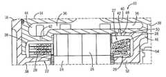
- FIG. 1is a cross-sectional view of an electric machine module according to one embodiment of the invention.
- FIG. 2is a partial cross-sectional view of portions of an electric machine module according to one embodiment of the invention
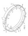
- FIG. 3is an isometric view of an end turn member according to one embodiment of the invention.
- FIG. 4is a partial cross-sectional view an end turn member according to one embodiment of the invention.
- FIG. 5is an isometric view of a stator assembly according to one embodiment of the invention.
- FIG. 1illustrates an electric machine module 10 according to one embodiment of the invention.
- the module 10can include a housing 12 comprising a sleeve member 14 , a first end cap 16 , and a second end cap 18 .
- An electric machine 20can be housed within a machine cavity 22 at least partially defined by the sleeve member 14 and the end caps 16 , 18 .
- the sleeve member 14 and the end caps 16 , 18can be coupled via conventional fasteners (not shown), or another suitable coupling method, to enclose at least a portion of the electric machine 20 within the machine cavity 22 .
- the housing 12can comprise a substantially cylindrical canister and a single end cap (not shown).
- the module housing 12can comprise materials that can generally include favorable thermally conductive properties, such as, but not limited to aluminum or other metals and materials capable of generally withstanding operating temperatures of the electric machine.
- the housing 12can be fabricated using different methods including casting, molding, extruding, and other similar manufacturing methods.
- the electric machine 20can include a rotor assembly 24 , a stator assembly 26 , including stator end turns 28 , and bearings 30 , and can be disposed about a shaft 34 .
- the stator assembly 26can substantially circumscribe at least a portion of the rotor assembly 24 .
- the rotor assembly 24can also include a rotor hub 32 or can have a “hub-less” design (not shown).
- the electric machine 20can be operatively coupled to the module housing 12 .
- the electric machine 20can be fit within the housing 12 .
- the electric machine 20can be fit within the housing 12 using an interference fit, a shrink fit, other similar friction-based fit that can at least partially operatively couple the machine 20 and the housing 12 .
- the stator assembly 26can be shrunk fit into the module housing 12 . Further, in some embodiments, the fit can at least partially secure the stator assembly 26 , and as a result, the electric machine 20 , in both axial and circumferential directions.
- the fit between the stator assembly 26 and the module housing 12can at least partially serve to transfer torque from the stator assembly 26 to the module housing 12 . In some embodiments, the fit can result in a generally greater amount of torque retained by the module 10 .
- the electric machine 20can be, without limitation, an electric motor, such as a hybrid electric motor, an electric generator, or a vehicle alternator.
- the electric machine 20can be a High Voltage Hairpin (HVH) electric motor or an interior permanent magnet electric motor for hybrid vehicle applications.
- HVHHigh Voltage Hairpin
- Components of the electric machine 20such as, but not limited to, the rotor assembly 24 , the stator assembly 26 , and the stator end turns 28 can generate heat during operation of the electric machine 20 . These components can be cooled to increase the performance and the lifespan of the electric machine 20 .
- the housing 12can comprise a coolant jacket 36 .
- the housing 12can include an inner wall 38 and an outer wall 40 and the coolant jacket 36 can be positioned substantially between at least a portion the walls 38 , 40 .
- the machine cavity 22can be at least partially defined by the inner wall 38 (e.g., each of the elements of the housing 12 can comprise a portion of the inner wall 38 ).
- the coolant jacket 36can substantially circumscribe at least a portion of the electric machine 20 . More specifically, in some embodiments, the coolant jacket 36 can substantially circumscribe at least a portion of an outer perimeter of the stator assembly 26 , including the stator end turns 28 .
- the coolant jacket 36can contain a coolant that can comprise transmission fluid, ethylene glycol, an ethylene glycol/water mixture, water, oil, motor oil, a gas, a mist, or a similar substance.
- the coolant jacket 36can be in fluid communication with a coolant source (not shown) which can pressurize the coolant prior to or as it is being dispersed into the coolant jacket 36 , so that the pressurized coolant can circulate through the coolant jacket 36 .
- the inner wall 38can include coolant apertures 42 so that the coolant jacket 36 can be in fluid communication with the machine cavity 22 .
- the coolant apertures 42can be positioned substantially adjacent to the stator end turns 28 .
- the coolantcan contact the stator end turns 28 , which can lead to at least partial cooling. After exiting the coolant apertures 42 , at least a portion of the coolant can flow through the machine cavity 22 and can contact various module 10 elements, which, in some embodiments, can lead to at least partial cooling of the module 10 .
- the coolant jacket 36can include multiple configurations. In some embodiments, at least a portion of the coolant jacket 36 can extend through the sleeve member 14 a distance substantially similar to an axial length of the stator assembly 26 . For example, in some embodiments, an axial length of a portion of the coolant jacket 36 can extend at least the same distance as the axial length of the stator assembly 26 , including the stator end turns 28 . In some embodiments, portions of the coolant jacket 36 can extend greater and lesser axial distances, as desired by manufacturers and/or end users for cooling.
- a portion of the coolant jacket 36also can comprise at least one radially inward extension 44 .
- a region of the inner wall 38can be substantially radially recessed so that the radially inward extension 44 of the coolant jacket 38 can be substantially adjacent to at least one of the stator end turns 28 .
- radially inward extensions 44can be positioned adjacent to one of, both of, or neither of the stator end turns 28 .
- the coolant jacket 36can comprise radially inward extensions 44 substantially continuously around at least a portion of an outer diameter of at least one of the stator end turns 28 (i.e., one continuous radially inward extension around a portion of at least one of the stator end turns 28 ).
- the coolant jacket 36can comprise substantially discrete radially inward extensions 44 positioned around at least a portion of an outer diameter 27 of at least one set of the stator end turns 28 .
- the housing 12can comprise at least two radially inward extensions 44 .
- the housing 12can comprise two halves coupled together in a substantially axially central location so that each half of the housing 12 can comprise a radially inward extension 44 and the electric machine 20 can be positioned substantially between the two halves.
- the stator end turns 28can comprise a generally lesser outer diameter compared to the stator assembly 26 , and, as a result, a greater distance can exist between the stator end turns 28 and the cooling jacket 36 .
- the radially inward extensions 44 of the coolant jacket 38can enhance module 10 cooling because some of the coolant can circulate relatively closer to the stator end turns 28 , compared to embodiments substantially lacking the radially inward extension 44 .
- a distance between the coolant and an area rejecting heat energyi.e., the stator end turns
- an end turn member 46can at least partially enhance module 10 operations.
- the end turn member 46can be substantially annular or ring shaped.
- the end turn member 46can comprise other shapes such as square, rectangular, regular and/or irregular polygonal, and other similar shapes.
- the end turn member 46can comprise a shape that is substantially similar to the general shape of the stator assembly 26 , including the stator end turns 28 .
- the end turn member 46can comprise a single structure, however, in other embodiments, the end turn member 46 can comprise multiple subunits coupled together.
- the end turn member 46can comprise materials that can generally include favorable thermally conductive properties, such as, but not limited to aluminum or other metals and materials capable of generally withstanding operating temperatures of the electric machine.
- the end turn member 46can be fabricated using different methods including casting, molding, extruding, and other similar manufacturing methods.
- the inner wall 38 of the housing 12can comprise the end turn member 46 .
- the end turn member 46can be coupled the inner wall 38 of one of the end caps 16 , 18 and/or the sleeve member 14 .
- the end turn member 46can be interference fit (e.g., press fit), welded, brazed, or otherwise coupled to the inner wall 38 using coupling methods such as, but not limited to conventional fasteners, adhesives, etc.
- the end turn member 46can comprise at least one feature 45 configured and arranged to at least partially enhance the interaction of the end turn member 46 and the housing 12 .
- the features 45can comprise apertures, recesses, grooves, flanges, extensions, and any other similar structures.
- the features 45can comprise a combination of configurations positioned around portions of a circumference of the end turn member 46 .
- the features 45can comprise multiple orientations such as radial, axial, circumferential, or any combination thereof.
- the inner wall 38 of the housing 12can comprise corresponding features (not shown) configured and arranged to engage the features 45 (e.g., the features 45 can receive a portion of the features of the housing 12 and/or vice versa) of the end turn member 46 to aid in coupling together at least these two elements.
- the features 45can substantially function as torque retention elements to help retain torque produced by the electric machine 20 during operations.
- the features 45can also function as alignment elements to aid in guiding and/or aligning the end turn member 46 during coupling to the housing 12 .
- the end turn member 46can be substantially integral with the housing 12 .
- the housing 12can be fabricated so that the end turn member 46 extends from the inner wall 38 of the housing 12 .
- the end turn member 46can be fabricated (e.g., casting, molding, extruding, etc.) as a portion of the housing 12 so that the elements are formed at substantially the same time and are substantially one element.
- the end turn member 46can be substantially integral with at least one of the end caps 16 , 18 and/or the sleeve member 14 so that upon coupling together the end caps 16 , 18 and the sleeve member 14 , as previously mentioned, the end turn member 46 can be positioned substantially adjacent to the stator assembly 26 .
- future referencesmay suggest a non-integral end turn member 46 , those references are in no way intended to excluded embodiments comprising a substantially integral end turn member 46 and elements of a substantially integral end turn member 46 .
- the end turn member 46can function to enhance cooling.
- the coolant jacket 36can comprise at least one radially inward extension 44 .
- installing the stator assembly 26 within the sleeve member 14can be complicated because of the relative dimensions of the stator assembly 26 and the stator end turns 28 .
- the module 10can comprise a radially inward extension 44 adjacent to one axial end of the stator assembly 26 and the end member 46 substantially adjacent to another axial end of the stator assembly 26 . Accordingly, in some embodiments, the end turn member 46 can aid in cooling at least a portion of the stator assembly 26 .
- the end turn member 46can be configured and arranged to direct a portion of the coolant.
- the end turn member 46can comprise at least one first member aperture 48 that can be configured and arranged to substantially align with at least one of the coolant apertures 42 upon positioning of the end turn member 46 adjacent to the electric machine 20 .
- the first member apertures 48can comprise a substantially radial orientation.
- the end turn member 46can comprise substantially the same number of first member apertures 48 as coolant apertures 42 so that when the end turn member 46 is positioned within the machine cavity 22 , at least a portion of the coolant exiting the coolant apertures 42 can also flow through the first member apertures 48 .
- the end turn member 46can comprise a radially outer flange 50 , a radially inner flange 52 , and a central region 54 . As shown in FIGS. 2-4 , in some embodiments, the end turn member 46 can be formed so that the flanges 50 , 52 axially extend into the machine cavity 22 from the central region 54 (e.g., the end turn member 46 can comprise a sideways-oriented “u” shape).
- the end turn member 46can be formed (e.g., cast, molded, machined, etc.) so that the radially outer flange 50 and the radially inner flange 52 can axially extend from the central region 54 so that at least a portion of the stator end turns 28 can be received within the end turn member 46 .
- the radially outer flange 50when the end turn member 46 is positioned substantially adjacent to the stator assembly 26 , can be substantially adjacent to the outer diameter 27 of the stator end turns 28 .
- the stator end turnscan comprise an inner diameter 29 .
- the radially inner flange 52can be substantially adjacent to the inner diameter 29 of the stator end turns, as shown in FIGS. 2 and 5 . Accordingly, in some embodiments, the central region 54 can be substantially adjacent to an axial outermost portion of at least a portion of the stator end turns 28 .
- the end turn member 46can at least partially enhance heat energy transfer.
- the end turn member 46can comprise a substantially thermally conductive material (e.g., aluminum), as previously mentioned.
- the end turn member 46can receive at least a portion of the heat energy produced by the end turns 28 during electric machine 20 operations.
- the end turn member 46can be immediately adjacent to the inner wall 38 of the housing 12 (e.g., friction fit, interference fit, substantially integral, etc.), which can lead to enhance heat energy transfer from the end turns 28 to the housing 12 via the end turn member 46 comprising thermally conductive materials.
- the flanges 50 , 52can further aid in cooling.
- the radially outer flange 50can comprise the first member apertures 48 so that at least a portion of the coolant can flow through both the coolant apertures 42 and the first member apertures 48 and can contact the stator end turns 28 .
- the end turn member 46can enhance cooling by retaining at least a portion of the coolant adjacent to the end turns 28 .
- the module 10can comprise a conventional drain system (not shown) generally positioned at the bottom of the module 10 so that at least a portion of the coolant can flow from the machine cavity 22 into the drain system.
- the drain systemcan fluidly connect the machine cavity 22 to a conventional heat exchange element (e.g., a radiator, a heat exchanger, etc.) that can be integral with, adjacent to, and/or remote from the module 10 (not shown).
- a conventional heat exchange elemente.g., a radiator, a heat exchanger, etc.
- at least a portion of the coolantcan circulate through the heat exchange element where at least a portion of the heat energy can be removed and the coolant can be re-circulated for further cooling.
- the coolantcan contact the end turn member 46 .
- the coolantcan at least partially accumulate immediately adjacent to the end turns 28 and/or bounce from the end turn member 46 to the end turns 28 .
- the end turn member 46can at least partially enhance cooling because it can function to retain at least a portion of the coolant in close proximity to the stator end turns 28 so that more heat energy can be conducted to the coolant.
- the end turn member 46can conduct at least a portion of the heat energy received from the stator end turns 28 to the housing 12 .
- the coolantcan conduct some of the heat energy to the end turn member 46 .
- the end turn member 46can be integral with and/or coupled to the housing 12 , the end turn member 46 can transfer at least a portion of the heat energy to the housing 12 , which can transfer the heat energy to the surrounding environment via convection.
- the housing 12 and/or the end turn member 46can conduct at least a portion of the heat energy into the coolant circulating through the coolant jacket 36 .
- the end turn member 46can function to enhance operations of the module 10 .
- the end turn member 46can comprise different geometries that could be relevant to module 10 operations and cooling.
- the end turn member 46can comprise a variety of annuli, additional apertures, slots, other geometries, or combinations thereof to aid in operations.
- some of these geometriescan at least partially serve to enhance cooling by further enhancing coolant accumulation substantially adjacent to the end turns 28 .
- the end turn member 46can ease manufacturing burdens.
- a module 10may require some of the previously mentioned geometries and/or configurations for operations (e.g., extra space near the end turns 28 or other space concerns).
- extra costscan be incurred in order to change the housing 12 manufacturing process.
- housing 12 manufacturingcan remain substantially the same and the geometries can be substantially integrated with the end turn member 46 .
- the end turn member 46in order to accommodate some special features of the electric machine 20 (e.g., special end turn portions, electrical connection points, etc.), can comprise at least some of the previously mentioned geometries to enable positioning of the electric machine 20 within the housing 12 . Accordingly, costs and manufacturing complexity can be minimized because simple machining can be performed on the housing 12 and more complex machining can be performed of the end turn member 46 .
- the end turn member 46can enhancing cooling in multiple module 10 configurations.
- the coolant jacket 36can comprise a substantially sealed configuration.
- coolantcan circulate through the jacket 36 , but does not enter the machine cavity 22 via the apertures 44 . Accordingly, coolant does not contact the stator end turns 28 , which, in some embodiments, can impact module 10 cooling.
- the end turn member 46can at least partially aid in cooling the stator end turns 28 where the coolant jacket 36 comprises a substantially sealed configuration.
- the end turn member 46can comprise a substantially non-conductive material so that the flanges 50 , 52 and the central region 54 can be substantially adjacent to portions of the end turns 28 , as previously mentioned.
- at least a portion of the heat energy produced by the stator end turns 28can be transferred to the end turn member 46 via convection.
- the end turn member 46can be integral with and/or coupled to the housing 12 , the end turn member 46 can transfer at least a portion of the heat energy to the housing 12 , which can transfer the heat energy to the surrounding environment via convection or coolant circulating through the coolant jacket 36 .
- the stator end turns 28can comprise a substantially potted configuration. In some embodiments, at least a portion of the stator end turns 28 can coated, encased, or otherwise covered in a potting composition that can at least partially enhance thermal conductivity away from the end turns 28 .
- the potting compositioncan comprise a resin.
- the potting compositioncan comprise an epoxy resin, although, the potting composition can comprise other resins.
- resinscan provide a generally appropriate dielectric constant, thermal conductivity, thermal expansion, chemical resistance, etc. for use in applications involving module 10 operational temperatures and current flow.
- the potting compositioncan be converted to a substantially liquid state (e.g., via heating) and gravity fed over the end turns 28 .
- the end turns 28can be placed in a mold prior to the gravity feed and/or injection so that the potting composition can cover at least a portion of the stator end turns 28 and can comprise a shape at least partially corresponding the shape of the mold.
- the potted stator end turns 28can comprise a shape and/or configuration desired by the manufacturer and/or end user.
- the potting compositioncan comprise a two-part mixture so that a first portion of the potting composition an a second portion of the potting composition can be mixed to activate the potting composition prior to application to the end turns 28 .
- the end turn member 46can aid in cooling the stator end turns 28 comprising a potted configuration.
- the potted end turns 28can be configured and arranged so that, after solidifying, the potting composition can be immediately adjacent to and/or contact the flanges 50 , 52 and the central region 54 .
- the potted stator end turns 28can conduct at least a portion of the heat energy produced by the stator end turns 28 to the housing 12 via the end turn member 46 .
- the potting compositioncan be generally thermally conductive so that at least a portion of the heat energy produced by the stator end turns 28 can be substantially conducted from the end turns 28 to the end turn member 46 via the potting composition.
- the end turn member 46can be used in potting at least a portion of the stator end turns 28 .
- the end turn member 46can function as the mold that can be used to form the potted stator end turns 28 .
- the stator assembly 26can be positioned with respect to the end turn member 46 so that at least a portion of the stator end turns 28 are positioned within the end turn member 46 (e.g., substantially adjacent to the flanges 50 , 52 and the central region 54 ), as previously mentioned.
- the potting compositioncan be gravity fed or injected around and through at least a portion of the stator end turns 28 so that the stator end turns 28 can be substantially enclosed by the potting composition, as previously mentioned.
- the end turn member 46can be in contact with the stator end turns 28 via the potting composition so that heat energy can be readily conducted after the potting composition cures.
- the end turn member 46can be used in the potting process before, during, and/or after assembly of the module 10 .
- the end turn member 46can comprise at least one second member aperture 56 .
- the end turn member 46can comprise a plurality of second member apertures 56 , as shown in FIG. 3 .
- the second member apertures 56can be disposed in a generally axial direction through a portion of the central region 54 , as illustrated in FIGS. 2-4 .
- the second member apertures 56can be, at least partially, circumferentially arranged with respect to the end turn member 46 .
- the second member apertures 56can be arranged in regular circumferential patterns (e.g., an aperture 56 positioned every 30 degrees) or irregular circumferential patterns.
- the inner wall 38 of the housing 12can comprise at least some second member apertures 56 so that at least some embodiments functioning without the end turn member 46 can operate as described below.
- the second member apertures 56can function as expansion joints. In some embodiments comprising at least some potted stator end turns 28 , the second member apertures 56 can function to account for potting composition expansion. For example, during operation of the electric machine 20 , the production of heat energy by at least a portion of the stator end turns 28 can cause thermal expansion of the potting material. As a result of the thermal expansion of the potting composition, in some embodiments, a force and/or pressure can be applied to at least a portion of the stator end turns 28 , the flanges 50 , 52 and/or the central region 54 , which can lead to damage to the end turn member 46 and/or the stator end turns 28 .
- the second member apertures 56can function to at least partially relieve the pressure associated with the thermal expansion of the potting composition.
- the potting compositionexpands, at least a portion of the potting composition can expand into and/or through the second member aperture 56 .
- the force and/or pressure exerted upon at least some of the stator end turns 28can be at least partially relieved by the second member apertures 56 , which can at least partially reduce the risk of damage to the stator end turns 28 and/or end turn member 46 stemming from potting composition thermal expansion.
- the second member apertures 56can be used in the potting process. In some embodiments, at least some of the second member apertures 56 can function as a potting composition inlet during the potting process. For example, in some embodiments, the potting composition can be gravity fed or injected around at least some portions of the stator end turns 28 , as previously mentioned. In some embodiments, however, another volume of potting composition can be fed around portions of the stator end turns 28 via at least some of the second member apertures 56 .
- the second member apertures 56can be substantially sealed (e.g. “capped-off”) with a sealing structure (not shown) so that the potting composition does not flow through the second member apertures 56 during the potting process. Then, once the potting composition has substantially solidified (e.g., cured), the sealing structure can be removed and the second member apertures 56 can function as expansion joints during module 10 operations, as previously mentioned. Furthermore, in some embodiments, the end turn member 46 can substantially lack at least a portion of the second member apertures 56 prior to use in the potting process. After the end turns 28 are potted in the potting composition, at least a portion of the second member apertures 56 can be formed (e.g., machined, drilled, punched, stamped, etc.) for use as previously mentioned.
- a sealing structurenot shown
Landscapes
- Engineering & Computer Science (AREA)
- Power Engineering (AREA)
- Motor Or Generator Frames (AREA)
- Motor Or Generator Cooling System (AREA)
Abstract
Description
Claims (16)
Priority Applications (5)
| Application Number | Priority Date | Filing Date | Title |
|---|---|---|---|
| US13/220,428US9048710B2 (en) | 2011-08-29 | 2011-08-29 | Electric machine module cooling system and method |
| PCT/US2012/052614WO2013033065A1 (en) | 2011-08-29 | 2012-08-28 | Electric machine module cooling system and method |
| KR1020147004670AKR20140057560A (en) | 2011-08-29 | 2012-08-28 | Electric machine module cooling system and method |
| DE112012003598.4TDE112012003598T5 (en) | 2011-08-29 | 2012-08-28 | System and method for cooling an electrical machine module |
| CN201280042123.0ACN103765736A (en) | 2011-08-29 | 2012-08-28 | Electric machine module cooling system and method |
Applications Claiming Priority (1)
| Application Number | Priority Date | Filing Date | Title |
|---|---|---|---|
| US13/220,428US9048710B2 (en) | 2011-08-29 | 2011-08-29 | Electric machine module cooling system and method |
Publications (2)
| Publication Number | Publication Date |
|---|---|
| US20130049496A1 US20130049496A1 (en) | 2013-02-28 |
| US9048710B2true US9048710B2 (en) | 2015-06-02 |
Family
ID=47742614
Family Applications (1)
| Application Number | Title | Priority Date | Filing Date |
|---|---|---|---|
| US13/220,428Active2034-02-10US9048710B2 (en) | 2011-08-29 | 2011-08-29 | Electric machine module cooling system and method |
Country Status (5)
| Country | Link |
|---|---|
| US (1) | US9048710B2 (en) |
| KR (1) | KR20140057560A (en) |
| CN (1) | CN103765736A (en) |
| DE (1) | DE112012003598T5 (en) |
| WO (1) | WO2013033065A1 (en) |
Cited By (8)
| Publication number | Priority date | Publication date | Assignee | Title |
|---|---|---|---|---|
| USD852938S1 (en) | 2018-05-07 | 2019-07-02 | S. C. Johnson & Son, Inc. | Dispenser |
| USD853548S1 (en) | 2018-05-07 | 2019-07-09 | S. C. Johnson & Son, Inc. | Dispenser |
| USD872245S1 (en) | 2018-02-28 | 2020-01-07 | S. C. Johnson & Son, Inc. | Dispenser |
| USD872847S1 (en) | 2018-02-28 | 2020-01-14 | S. C. Johnson & Son, Inc. | Dispenser |
| USD878538S1 (en) | 2018-02-28 | 2020-03-17 | S. C. Johnson & Son, Inc. | Dispenser |
| USD881365S1 (en) | 2018-02-28 | 2020-04-14 | S. C. Johnson & Son, Inc. | Dispenser |
| CN113302822A (en)* | 2019-04-01 | 2021-08-24 | 宝马股份公司 | Cooling device for a stator of an electric machine, electric machine and motor vehicle |
| US20220209617A1 (en)* | 2020-12-30 | 2022-06-30 | Dana Heavy Vehicle Systems Group, Llc | Systems and method for an electric motor with molded coolant jacket and spray ring |
Families Citing this family (15)
| Publication number | Priority date | Publication date | Assignee | Title |
|---|---|---|---|---|
| US10069375B2 (en)* | 2012-05-02 | 2018-09-04 | Borgwarner Inc. | Electric machine module cooling system and method |
| KR20150129829A (en)* | 2013-03-14 | 2015-11-20 | 알리손 트랜스미션, 인크. | Stator sleeve with integrated cooling for hybrid/electric drive motor |
| JP5924352B2 (en)* | 2014-01-23 | 2016-05-25 | 株式会社デンソー | Rotating electric machine |
| EP3123594A1 (en) | 2014-03-27 | 2017-02-01 | Prippel Technologies, LLC | Induction motor with transverse liquid cooled rotor and stator |
| EP3207317B1 (en)* | 2014-07-21 | 2022-12-07 | Prime Datum Development Company, LLC | Cooling tower having thermally managed motor |
| JP6599985B2 (en) | 2014-07-25 | 2019-10-30 | プリペル テクノロジーズ,リミティド ライアビリティ カンパニー | Fluid cooled wound strip structure |
| US11255612B2 (en) | 2014-07-25 | 2022-02-22 | Enure, Inc. | Wound strip machine |
| US10756583B2 (en) | 2014-07-25 | 2020-08-25 | Enure, Inc. | Wound strip machine |
| CN107078569A (en)* | 2014-09-18 | 2017-08-18 | 普里派尔技术有限公司 | Motor end turn cooling device |
| WO2016123507A1 (en) | 2015-01-30 | 2016-08-04 | Prippel Technologies, Llc | Electric machine stator with liquid cooled teeth |
| JP6871077B2 (en)* | 2017-06-13 | 2021-05-12 | 本田技研工業株式会社 | Motor generator device |
| DE102017220856A1 (en)* | 2017-11-22 | 2019-06-06 | Bayerische Motoren Werke Aktiengesellschaft | Cooling cap for a stator of an electrical machine of a motor vehicle, stator and motor vehicle |
| JP2019097347A (en)* | 2017-11-27 | 2019-06-20 | 本田技研工業株式会社 | Cooling structure of rotary electric machine and vehicle provided with the same |
| JP7412133B2 (en)* | 2019-10-29 | 2024-01-12 | 東洋電装株式会社 | Stator and stator manufacturing method |
| US12278540B2 (en)* | 2022-09-28 | 2025-04-15 | Honda Motor Co., Ltd. | Cooling structure of vertical motor |
Citations (155)
| Publication number | Priority date | Publication date | Assignee | Title |
|---|---|---|---|---|
| US2080678A (en) | 1936-02-15 | 1937-05-18 | Byron Jackson Co | Motor construction |
| US2264616A (en) | 1938-09-21 | 1941-12-02 | John C Buckbee | Rotary compressor |
| US3155856A (en) | 1960-11-14 | 1964-11-03 | Westinghouse Electric Corp | Dynamoelectric machinery |
| US3447002A (en) | 1965-03-17 | 1969-05-27 | Asea Ab | Rotating electrical machine with liquid-cooled laminated stator core |
| US3525001A (en) | 1968-09-23 | 1970-08-18 | Preco Inc | Liquid cooled electric motor |
| US3748507A (en) | 1971-12-02 | 1973-07-24 | Gen Electric | Variable speed drive having enhanced ventilation |
| US4038570A (en) | 1974-03-20 | 1977-07-26 | Durley Iii Benton A | Ultrasonic piezoelectric transducer drive circuit |
| US4710662A (en) | 1985-12-09 | 1987-12-01 | General Electric Company | Dynamoelectric machine rotor structure having improved insulation |
| US5081382A (en) | 1990-10-01 | 1992-01-14 | Sundstrand Corporation | Generator end turn cooling using oil flow control tubes |
| US5180004A (en) | 1992-06-19 | 1993-01-19 | General Motors Corporation | Integral heater-evaporator core |
| JPH05103445A (en) | 1991-10-05 | 1993-04-23 | Fanuc Ltd | Liquid-cooled motor and its jacket |
| US5207121A (en) | 1992-02-13 | 1993-05-04 | General Motors Corporation | Gear case for locomotive drive system |
| JPH05292704A (en) | 1992-04-14 | 1993-11-05 | Toshiba Corp | Rotor abnormality monitoring device |
| US5293089A (en) | 1989-12-15 | 1994-03-08 | Robert Bosch Gmbh | Liquid-cooled electric generator |
| JPH0636364U (en) | 1992-10-13 | 1994-05-13 | 神鋼電機株式会社 | Cooling mechanism for outer-rotor type high-speed rotating electric machine |
| JPH06311691A (en) | 1993-04-15 | 1994-11-04 | Meidensha Corp | Motor for electric car |
| US5372213A (en) | 1991-10-24 | 1994-12-13 | Aisin Aw Co., Ltd. | Oil circulating system for electric vehicle |
| JPH07264810A (en) | 1994-03-17 | 1995-10-13 | Okuma Mach Works Ltd | Liquid-cooled motor |
| JPH0819218A (en) | 1994-06-28 | 1996-01-19 | Honda Motor Co Ltd | Cooling structure of rotating electric machine |
| US5519269A (en) | 1994-06-10 | 1996-05-21 | Westinghouse Electric Corp. | Electric induction motor and related method of cooling |
| JPH0946973A (en) | 1995-07-28 | 1997-02-14 | Nikkiso Co Ltd | Motor rotor cooling structure |
| US5616973A (en) | 1994-06-29 | 1997-04-01 | Yeomans Chicago Corporation | Pump motor housing with improved cooling means |
| JPH09154257A (en) | 1995-11-28 | 1997-06-10 | Nippei Toyama Corp | Built-in motor |
| JPH10234157A (en) | 1997-02-19 | 1998-09-02 | Toshiba Corp | motor |
| US5859482A (en) | 1997-02-14 | 1999-01-12 | General Electric Company | Liquid cooled electric motor frame |
| JPH11132867A (en) | 1997-09-10 | 1999-05-21 | Pfeiffer Vacuum Gmbh | Temperature monitoring device |
| US5923108A (en) | 1996-07-30 | 1999-07-13 | Ebara Corporation | Canned motor |
| JPH11206063A (en) | 1997-12-26 | 1999-07-30 | Toyota Motor Corp | ELECTRIC MOTOR, POWER TRANSMISSION DEVICE, AND ITS MANUFACTURING METHOD |
| US5937817A (en) | 1998-06-23 | 1999-08-17 | Harley-Davidson Motor Company | Dry sump oil cooling system |
| US5965965A (en) | 1997-05-26 | 1999-10-12 | Denso Corporation | Stator winding arrangement of alternator for vehicle |
| US6011332A (en) | 1997-05-26 | 2000-01-04 | Denso Corporation | Stator cooling arrangement of alternator for vehicle |
| KR20000013908A (en) | 1998-08-14 | 2000-03-06 | 에릭 발리베 | Cooling system of alternating current generator for cars |
| JP2000152563A (en) | 1998-11-09 | 2000-05-30 | Railway Technical Res Inst | Fully-closed cooling rotary electric machine |
| JP2000152561A (en) | 1998-11-10 | 2000-05-30 | Toshiba Transport Eng Inc | Ventilation filter and ventilation cooling type rotary electric machine having ventilation filter |
| US6069424A (en) | 1996-05-02 | 2000-05-30 | Chrysler Corporation | Stator cooling |
| US6075304A (en) | 1997-04-30 | 2000-06-13 | Alon Co., Ltd | Stator with molded encasement for small motors and manufacturing process therefor |
| US6087746A (en) | 1997-06-19 | 2000-07-11 | Valeo Equipements Electriques Moteur | Alternator with improved cooling means, especially for motor vehicles |
| US6097130A (en) | 1997-05-26 | 2000-08-01 | Denso Corporation | Alternator for vehicle |
| US6095754A (en) | 1998-05-06 | 2000-08-01 | Applied Materials, Inc. | Turbo-Molecular pump with metal matrix composite rotor and stator |
| US6114784A (en) | 1998-06-22 | 2000-09-05 | Nissan Motor Co., Ltd. | Motor with cooling structure |
| US6147430A (en) | 1998-05-25 | 2000-11-14 | Denso Corporation | Stator of AC generator for vehicle |
| US6147432A (en) | 1998-08-06 | 2000-11-14 | Denso Corporation | AC generator stator for vehicle |
| JP2000324757A (en) | 1999-05-07 | 2000-11-24 | Toshiba Corp | Outer rotor type motor |
| JP2000333409A (en) | 1999-05-21 | 2000-11-30 | Matsushita Electric Ind Co Ltd | Induction motor |
| US6173758B1 (en) | 1999-08-02 | 2001-01-16 | General Motors Corporation | Pin fin heat sink and pin fin arrangement therein |
| US6181043B1 (en) | 1997-12-10 | 2001-01-30 | Denso Corporation | Alternator for vehicle |
| US6201321B1 (en) | 1998-06-05 | 2001-03-13 | Bayside Controls, Inc. | Apparatus and method for dissipating heat from a motor |
| US6208060B1 (en) | 1998-05-25 | 2001-03-27 | Denso Corporation | Stator of vehicle AC generator and method of manufacturing the same |
| US6232687B1 (en) | 1999-03-25 | 2001-05-15 | General Electric Company | Electric motor having snap connection assembly |
| US6242836B1 (en) | 1998-06-26 | 2001-06-05 | Denso Corporation | Vehicle AC generators stator and method of manufacturing the same |
| US6278206B1 (en) | 2000-06-28 | 2001-08-21 | Visteon Global Technologies, Inc. | Electrical connection apparatus and method for connecting an alternator stator |
| US6291918B1 (en) | 1997-05-26 | 2001-09-18 | Denso Corporation | Alternator for vehicle |
| US6300693B1 (en) | 1999-03-05 | 2001-10-09 | Emerson Electric Co. | Electric motor cooling jacket assembly and method of manufacture |
| US6313559B1 (en) | 1999-04-14 | 2001-11-06 | Denso Corporation | Stator arrangement of rotary electric machine |
| JP2001333559A (en) | 2000-05-19 | 2001-11-30 | Nissan Motor Co Ltd | Motor stator |
| US6333537B1 (en) | 1998-02-23 | 2001-12-25 | Nec Corporation | Thin film capacitor with an improved top electrode |
| US6335583B1 (en) | 1998-05-25 | 2002-01-01 | Denso Corporation | Stator of vehicle AC generator and method of manufacturing the same |
| US6346758B1 (en) | 1999-07-12 | 2002-02-12 | Denso Corporation | Rotary electric machine and method of manufacturing the same |
| US6359232B1 (en) | 1996-12-19 | 2002-03-19 | General Electric Company | Electrical insulating material and stator bar formed therewith |
| JP2002095217A (en) | 2000-09-18 | 2002-03-29 | Hitachi Ltd | AC generator for vehicles |
| JP2002119019A (en) | 2000-10-11 | 2002-04-19 | Honda Motor Co Ltd | Motor cooling structure |
| US6404628B1 (en) | 2000-07-21 | 2002-06-11 | General Motors Corporation | Integrated power electronics cooling housing |
| US20020074889A1 (en)* | 2000-12-14 | 2002-06-20 | Toshio Kikuchi | Rotating electric machine and method of manufacture therefor |
| US6417592B2 (en) | 1999-12-09 | 2002-07-09 | Denso Corporation | Rotary electric machine for vehicle |
| US6445095B1 (en) | 2001-01-11 | 2002-09-03 | Ford Global Technologies, Inc. | Electric machine with laminated cooling rings |
| US6459177B1 (en) | 1999-08-06 | 2002-10-01 | Denso Corporation | Electric rotary machine having a plurality of conductor segments and method of manufacturing the same |
| US20020180284A1 (en) | 2001-04-20 | 2002-12-05 | Leflem Graham | Cooling of electrical machines |
| US6509665B1 (en) | 1999-10-25 | 2003-01-21 | Matsushita Electric Industial Co., Ltd. | Motor having stator with insulator of high heat-conductivity |
| US6515392B2 (en) | 2000-11-30 | 2003-02-04 | Denso Corporation | Vehicle AC generator |
| US6522043B2 (en) | 2001-01-19 | 2003-02-18 | Denso Corporation | Vehicle AC generator |
| US6559572B2 (en) | 2000-04-14 | 2003-05-06 | Denso Corporation | Stator core of vehicle rotary electric machine and method of manufacturing the same |
| US6579202B2 (en) | 2000-12-18 | 2003-06-17 | General Motors Corporation | Lubrication and cooling system for power receiving and delivery units in an electro-mechanical vehicular transmission |
| JP2003250247A (en) | 2002-02-22 | 2003-09-05 | Nissan Motor Co Ltd | Motor cooling device |
| JP2003299317A (en) | 2002-04-03 | 2003-10-17 | Toyota Motor Corp | Electric device for vehicle drive |
| JP2003324901A (en) | 2002-04-26 | 2003-11-14 | Nippon Soken Inc | Electric motor |
| US20030222519A1 (en) | 2002-05-28 | 2003-12-04 | Emerson Electric Co. | Cooling jacket for electric machines |
| US20040036367A1 (en) | 2002-01-30 | 2004-02-26 | Darin Denton | Rotor cooling apparatus |
| JP2004215353A (en)* | 2002-12-27 | 2004-07-29 | Toyota Motor Corp | Rotating electric machine |
| US6770999B2 (en) | 2002-03-01 | 2004-08-03 | Denso Corporation | Stator of vehicle ac generator |
| JP2004236376A (en) | 2003-01-28 | 2004-08-19 | Nissan Motor Co Ltd | Internal cooling motor |
| JP2004248402A (en) | 2003-02-13 | 2004-09-02 | Toyota Motor Corp | Vehicle drive system |
| US20040189110A1 (en) | 1999-09-03 | 2004-09-30 | Kazumasa Ide | Rotating electric machine and cooling method thereof |
| US20040195929A1 (en) | 2003-04-04 | 2004-10-07 | Nissan Motor Co., Ltd. | Stator of two rotor single stator type electric motor |
| JP2004297924A (en) | 2003-03-27 | 2004-10-21 | Nissan Motor Co Ltd | Cooling structure of rotating electric machine |
| JP2004312886A (en) | 2003-04-08 | 2004-11-04 | Suzuki Motor Corp | Cooling structure of electric motor |
| JP2004357472A (en) | 2003-05-30 | 2004-12-16 | Suzuki Motor Corp | Cooling structure of motor |
| JP2005012989A (en) | 2003-05-28 | 2005-01-13 | Toyota Motor Corp | Stator cooling structure in rotating electrical machines |
| US20050023266A1 (en) | 2002-02-25 | 2005-02-03 | Futek Furnace Inc. | Heat treatment apparatus and method |
| US20050023909A1 (en) | 2002-06-13 | 2005-02-03 | Cromas Joseph Charles | Automotive generator |
| JP2005057957A (en) | 2003-08-07 | 2005-03-03 | Kawasaki Heavy Ind Ltd | Electric motor |
| US6897594B2 (en) | 2002-01-18 | 2005-05-24 | Denso Corporation | Stator for a vehicular rotary electric machine and a manufacturing method thereof |
| US6903471B2 (en) | 2002-04-01 | 2005-06-07 | Nissan Motor Co., Ltd. | Stator cooling structure for multi-shaft, multi-layer electric motor |
| JP2005168265A (en) | 2003-12-05 | 2005-06-23 | Nissan Motor Co Ltd | Cooling structure of rotating electric machine |
| US20050194551A1 (en) | 2002-06-18 | 2005-09-08 | Siemens Aktiengesellschaft | Corona shield, and method of making a corona shield |
| US20050274450A1 (en) | 2004-06-15 | 2005-12-15 | Smith James B | Compression of resin impregnated insulating tapes |
| US20050285456A1 (en) | 2002-09-27 | 2005-12-29 | Hitachi, Ltd. | Method of manufacturing a resin-molded stator |
| US6998749B2 (en) | 2002-07-11 | 2006-02-14 | Denso Corporation | Rotary electric machine |
| US7002267B2 (en) | 2004-03-22 | 2006-02-21 | General Motors Corporation | Method and apparatus for cooling a hybrid transmission electric motor |
| JP2006060914A (en) | 2004-08-19 | 2006-03-02 | Mitsubishi Motors Corp | Motor cooling structure and manufacturing method thereof |
| US7026733B2 (en) | 2002-02-22 | 2006-04-11 | Daimlerchrysler Ag | Drive system for a motor vehicle having an electric machine |
| KR20060102496A (en) | 2005-03-23 | 2006-09-27 | 가부시끼가이샤 도시바 | Totally closed external motor |
| JP2006297541A (en) | 2005-04-20 | 2006-11-02 | Nsk Ltd | Rotary axis device for machine tools |
| JP2006528879A (en) | 2003-05-26 | 2006-12-21 | ヴァレオ エキプマン エレクトリク モトゥール | Rotating electrical machines such as automotive alternators |
| US20070024130A1 (en) | 2003-08-01 | 2007-02-01 | Siemens Aktiengesellschaft | Electric machine with rotor cooling and corresponding cooling method |
| US20070052313A1 (en) | 2005-09-07 | 2007-03-08 | Kabushiki Kaisha Toshiba | Rotating electrical machine |
| KR20070027809A (en) | 2005-08-29 | 2007-03-12 | 한국기계연구원 | Low noise oil supply |
| US20070063607A1 (en) | 2005-09-21 | 2007-03-22 | Toyota Jidosha Kabushiki Kaisha | Permanent magnet type rotating electric machine capable of suppressing deformation of rotor core |
| US20070145836A1 (en) | 2005-12-22 | 2007-06-28 | Emerson Electric Co. | Winding lead cooling for motor with heat-sensitive electronic components |
| US20070149073A1 (en) | 2002-06-18 | 2007-06-28 | Siemens Aktiengesellschaft | Electric machine with a corona shield |
| US7239055B2 (en) | 2004-07-28 | 2007-07-03 | Gm Global Technology Operations, Inc. | Motor cooling system |
| US20070216236A1 (en) | 2006-03-14 | 2007-09-20 | Ward Terence G | Method and apparatus for heat removal from electric motor winding end-turns |
| US7276006B2 (en) | 2004-03-22 | 2007-10-02 | General Motors Corporation | Transmission case for lube return and method |
| US7284313B2 (en) | 2004-03-22 | 2007-10-23 | General Motors Corporation | Method for assembling a hybrid electro-mechanical transmission |
| JP2007282341A (en) | 2006-04-04 | 2007-10-25 | Shimadzu Corp | Motor with cooling mechanism |
| JP2008021950A (en) | 2006-07-14 | 2008-01-31 | Fujitsu Ltd | Semiconductor device and manufacturing method thereof |
| US7339300B2 (en) | 2004-07-28 | 2008-03-04 | Gm Global Technology Operations, Inc. | Structural support member for stator retention and method of assembling an electromechanical transmission |
| US7352091B2 (en) | 2004-09-01 | 2008-04-01 | Remy International, Inc. | Electronic package for electrical machine |
| US7402923B2 (en) | 2004-07-29 | 2008-07-22 | General Motors Corporation | Electrically variable transmission |
| JP2008206213A (en) | 2007-02-16 | 2008-09-04 | Mitsubishi Motors Corp | Electric vehicle motor structure |
| JP2008219960A (en) | 2007-02-28 | 2008-09-18 | Toyota Central R&D Labs Inc | Rotating electric machine |
| US20080223557A1 (en)* | 2007-03-16 | 2008-09-18 | Remy Technologies, L.L.C. | Liquid cooling system of an electric machine |
| US20080278011A1 (en) | 2007-05-10 | 2008-11-13 | Bernd Peter Elgas | Stator assembly for use in a fluid-cooled motor and method of making the same |
| JP2008544733A (en) | 2005-06-16 | 2008-12-04 | シーメンス アクチエンゲゼルシヤフト | Rotor-cooled permanent magnet excitation type electric machine |
| US7508100B2 (en) | 2004-03-22 | 2009-03-24 | General Motors Corporation | Electric motor/generator and method of cooling an electromechanical transmission |
| KR20090048028A (en) | 2007-11-09 | 2009-05-13 | 현대자동차주식회사 | Hybrid vehicle motor cooling apparatus and method |
| US7538457B2 (en) | 2006-01-27 | 2009-05-26 | General Motors Corporation | Electric motor assemblies with coolant flow for concentrated windings |
| US20090174278A1 (en) | 2008-01-08 | 2009-07-09 | General Electric Company | Stator Bar Components with High Thermal Conductivity |
| US20090206687A1 (en) | 2008-02-15 | 2009-08-20 | Gm Global Technology Operations, Inc. | Cooling systems and methods for integrated electric motor-inverters |
| US7592045B2 (en) | 2004-06-15 | 2009-09-22 | Siemens Energy, Inc. | Seeding of HTC fillers to form dendritic structures |
| JP2009247084A (en) | 2008-03-31 | 2009-10-22 | Hitachi Ltd | Rotary electric machine and vehicle |
| JP2009247085A (en) | 2008-03-31 | 2009-10-22 | Hitachi Ltd | Rotary electric machine |
| US20090267426A1 (en) | 2006-04-09 | 2009-10-29 | Klaus Graner | Liquid-cooled electric machine and method for cooling such electric machine |
| JP2009254205A (en) | 2008-04-10 | 2009-10-29 | Mitsuba Corp | Electric motor |
| US7615951B2 (en) | 2006-09-08 | 2009-11-10 | Gm Global Technology Operations, Inc. | Method and system for limiting the operating temperature of an electric motor |
| US7615903B2 (en) | 2006-04-27 | 2009-11-10 | Gm Global Technology Operations, Inc. | Structural support member for electric motor/generator in electromechanical transmission |
| US20100026111A1 (en) | 2006-09-22 | 2010-02-04 | Siemens Aktiengesellschaft | Stator for an electrical machine with liquid cooling |
| JP2010028908A (en) | 2008-07-16 | 2010-02-04 | Toyota Motor Corp | Rotor of rotating electrical machine |
| JP2010028958A (en) | 2008-07-17 | 2010-02-04 | Toyota Motor Corp | Rotating electrical machine and cooling system of rotating electrical machine |
| JP2010035265A (en) | 2008-07-25 | 2010-02-12 | Meidensha Corp | Temperature-measuring device for rotor of electric motor |
| US7667359B2 (en) | 2005-12-02 | 2010-02-23 | Delta Electronics, Inc. | Stator structure and manufacturing method thereof |
| US20100045125A1 (en)* | 2008-08-22 | 2010-02-25 | Aisin Aw Co., Ltd. | Rotary electric machine |
| JP2010063253A (en) | 2008-09-03 | 2010-03-18 | Toyota Motor Corp | Rotor |
| US20100102649A1 (en) | 2008-10-24 | 2010-04-29 | Deere & Company | Hydroformed cooling channels in stator laminations |
| US20100109454A1 (en) | 2008-11-06 | 2010-05-06 | Emerson Electric Co. | Liquid deflecting baffle for an electric motor |
| JP2010121701A (en) | 2008-11-19 | 2010-06-03 | Ntn Corp | In-wheel motor driving device |
| US20100176668A1 (en) | 2009-01-15 | 2010-07-15 | Aisin Aw Co., Ltd. | Stator |
| JP2010246268A (en) | 2009-04-06 | 2010-10-28 | Toyota Motor Corp | Rotating electric machine |
| US20100320851A1 (en) | 2009-06-17 | 2010-12-23 | Deere & Company | Internal oil cooling via housing end brackets for an electric machine |
| US20110050141A1 (en) | 2009-08-31 | 2011-03-03 | Gm Global Technology Operations, Inc. | Electric motor stator winding temperature estimation |
| US20110101700A1 (en) | 2009-11-05 | 2011-05-05 | Henrik Stiesdal | Arrangement for Cooling of an Electrical Machine |
| US7939975B2 (en) | 2007-10-26 | 2011-05-10 | E. I Du Pont De Nemours And Company | Over-mold stator assembly and process for preparation thereof |
| US20110109095A1 (en) | 2009-11-06 | 2011-05-12 | Henrik Stiesdal | Arrangement for cooling of an electrical generator |
| US8067865B2 (en) | 2008-10-28 | 2011-11-29 | Caterpillar Inc. | Electric motor/generator low hydraulic resistance cooling mechanism |
| US8068327B2 (en) | 2005-07-25 | 2011-11-29 | Lenze Drives Gmbh | Holding device for encased high-protective capacitors |
| US8552600B2 (en) | 2010-06-14 | 2013-10-08 | Remy Technologies, Llc | Potted end turns of an electric machine |
Family Cites Families (1)
| Publication number | Priority date | Publication date | Assignee | Title |
|---|---|---|---|---|
| CN101847909A (en)* | 2010-05-21 | 2010-09-29 | 宝鸡忠诚机床股份有限公司 | Cooling method of high-speed lathe electric main shaft part and structure thereof |
- 2011
- 2011-08-29USUS13/220,428patent/US9048710B2/enactiveActive
- 2012
- 2012-08-28DEDE112012003598.4Tpatent/DE112012003598T5/enactivePending
- 2012-08-28CNCN201280042123.0Apatent/CN103765736A/enactivePending
- 2012-08-28KRKR1020147004670Apatent/KR20140057560A/ennot_activeCeased
- 2012-08-28WOPCT/US2012/052614patent/WO2013033065A1/enactiveApplication Filing
Patent Citations (160)
| Publication number | Priority date | Publication date | Assignee | Title |
|---|---|---|---|---|
| US2080678A (en) | 1936-02-15 | 1937-05-18 | Byron Jackson Co | Motor construction |
| US2264616A (en) | 1938-09-21 | 1941-12-02 | John C Buckbee | Rotary compressor |
| US3155856A (en) | 1960-11-14 | 1964-11-03 | Westinghouse Electric Corp | Dynamoelectric machinery |
| US3447002A (en) | 1965-03-17 | 1969-05-27 | Asea Ab | Rotating electrical machine with liquid-cooled laminated stator core |
| US3525001A (en) | 1968-09-23 | 1970-08-18 | Preco Inc | Liquid cooled electric motor |
| US3748507A (en) | 1971-12-02 | 1973-07-24 | Gen Electric | Variable speed drive having enhanced ventilation |
| US4038570A (en) | 1974-03-20 | 1977-07-26 | Durley Iii Benton A | Ultrasonic piezoelectric transducer drive circuit |
| US4710662A (en) | 1985-12-09 | 1987-12-01 | General Electric Company | Dynamoelectric machine rotor structure having improved insulation |
| US5293089A (en) | 1989-12-15 | 1994-03-08 | Robert Bosch Gmbh | Liquid-cooled electric generator |
| US5081382A (en) | 1990-10-01 | 1992-01-14 | Sundstrand Corporation | Generator end turn cooling using oil flow control tubes |
| JPH05103445A (en) | 1991-10-05 | 1993-04-23 | Fanuc Ltd | Liquid-cooled motor and its jacket |
| US5372213A (en) | 1991-10-24 | 1994-12-13 | Aisin Aw Co., Ltd. | Oil circulating system for electric vehicle |
| US5207121A (en) | 1992-02-13 | 1993-05-04 | General Motors Corporation | Gear case for locomotive drive system |
| JPH05292704A (en) | 1992-04-14 | 1993-11-05 | Toshiba Corp | Rotor abnormality monitoring device |
| US5180004A (en) | 1992-06-19 | 1993-01-19 | General Motors Corporation | Integral heater-evaporator core |
| JPH0636364U (en) | 1992-10-13 | 1994-05-13 | 神鋼電機株式会社 | Cooling mechanism for outer-rotor type high-speed rotating electric machine |
| JPH06311691A (en) | 1993-04-15 | 1994-11-04 | Meidensha Corp | Motor for electric car |
| JPH07264810A (en) | 1994-03-17 | 1995-10-13 | Okuma Mach Works Ltd | Liquid-cooled motor |
| US5519269A (en) | 1994-06-10 | 1996-05-21 | Westinghouse Electric Corp. | Electric induction motor and related method of cooling |
| JPH0819218A (en) | 1994-06-28 | 1996-01-19 | Honda Motor Co Ltd | Cooling structure of rotating electric machine |
| US5616973A (en) | 1994-06-29 | 1997-04-01 | Yeomans Chicago Corporation | Pump motor housing with improved cooling means |
| JPH0946973A (en) | 1995-07-28 | 1997-02-14 | Nikkiso Co Ltd | Motor rotor cooling structure |
| JPH09154257A (en) | 1995-11-28 | 1997-06-10 | Nippei Toyama Corp | Built-in motor |
| US6069424A (en) | 1996-05-02 | 2000-05-30 | Chrysler Corporation | Stator cooling |
| US5923108A (en) | 1996-07-30 | 1999-07-13 | Ebara Corporation | Canned motor |
| US6359232B1 (en) | 1996-12-19 | 2002-03-19 | General Electric Company | Electrical insulating material and stator bar formed therewith |
| US5859482A (en) | 1997-02-14 | 1999-01-12 | General Electric Company | Liquid cooled electric motor frame |
| JPH10234157A (en) | 1997-02-19 | 1998-09-02 | Toshiba Corp | motor |
| US6075304A (en) | 1997-04-30 | 2000-06-13 | Alon Co., Ltd | Stator with molded encasement for small motors and manufacturing process therefor |
| US6291918B1 (en) | 1997-05-26 | 2001-09-18 | Denso Corporation | Alternator for vehicle |
| US5965965A (en) | 1997-05-26 | 1999-10-12 | Denso Corporation | Stator winding arrangement of alternator for vehicle |
| US6011332A (en) | 1997-05-26 | 2000-01-04 | Denso Corporation | Stator cooling arrangement of alternator for vehicle |
| US6097130A (en) | 1997-05-26 | 2000-08-01 | Denso Corporation | Alternator for vehicle |
| US6087746A (en) | 1997-06-19 | 2000-07-11 | Valeo Equipements Electriques Moteur | Alternator with improved cooling means, especially for motor vehicles |
| JPH11132867A (en) | 1997-09-10 | 1999-05-21 | Pfeiffer Vacuum Gmbh | Temperature monitoring device |
| US6181043B1 (en) | 1997-12-10 | 2001-01-30 | Denso Corporation | Alternator for vehicle |
| JPH11206063A (en) | 1997-12-26 | 1999-07-30 | Toyota Motor Corp | ELECTRIC MOTOR, POWER TRANSMISSION DEVICE, AND ITS MANUFACTURING METHOD |
| US6333537B1 (en) | 1998-02-23 | 2001-12-25 | Nec Corporation | Thin film capacitor with an improved top electrode |
| US6095754A (en) | 1998-05-06 | 2000-08-01 | Applied Materials, Inc. | Turbo-Molecular pump with metal matrix composite rotor and stator |
| US6335583B1 (en) | 1998-05-25 | 2002-01-01 | Denso Corporation | Stator of vehicle AC generator and method of manufacturing the same |
| US6208060B1 (en) | 1998-05-25 | 2001-03-27 | Denso Corporation | Stator of vehicle AC generator and method of manufacturing the same |
| US6147430A (en) | 1998-05-25 | 2000-11-14 | Denso Corporation | Stator of AC generator for vehicle |
| US6201321B1 (en) | 1998-06-05 | 2001-03-13 | Bayside Controls, Inc. | Apparatus and method for dissipating heat from a motor |
| US6114784A (en) | 1998-06-22 | 2000-09-05 | Nissan Motor Co., Ltd. | Motor with cooling structure |
| US5937817A (en) | 1998-06-23 | 1999-08-17 | Harley-Davidson Motor Company | Dry sump oil cooling system |
| US6242836B1 (en) | 1998-06-26 | 2001-06-05 | Denso Corporation | Vehicle AC generators stator and method of manufacturing the same |
| US6147432A (en) | 1998-08-06 | 2000-11-14 | Denso Corporation | AC generator stator for vehicle |
| KR20000013908A (en) | 1998-08-14 | 2000-03-06 | 에릭 발리베 | Cooling system of alternating current generator for cars |
| JP2000152563A (en) | 1998-11-09 | 2000-05-30 | Railway Technical Res Inst | Fully-closed cooling rotary electric machine |
| JP2000152561A (en) | 1998-11-10 | 2000-05-30 | Toshiba Transport Eng Inc | Ventilation filter and ventilation cooling type rotary electric machine having ventilation filter |
| US6300693B1 (en) | 1999-03-05 | 2001-10-09 | Emerson Electric Co. | Electric motor cooling jacket assembly and method of manufacture |
| US6232687B1 (en) | 1999-03-25 | 2001-05-15 | General Electric Company | Electric motor having snap connection assembly |
| US6313559B1 (en) | 1999-04-14 | 2001-11-06 | Denso Corporation | Stator arrangement of rotary electric machine |
| JP2000324757A (en) | 1999-05-07 | 2000-11-24 | Toshiba Corp | Outer rotor type motor |
| JP2000333409A (en) | 1999-05-21 | 2000-11-30 | Matsushita Electric Ind Co Ltd | Induction motor |
| US6346758B1 (en) | 1999-07-12 | 2002-02-12 | Denso Corporation | Rotary electric machine and method of manufacturing the same |
| US6173758B1 (en) | 1999-08-02 | 2001-01-16 | General Motors Corporation | Pin fin heat sink and pin fin arrangement therein |
| US6459177B1 (en) | 1999-08-06 | 2002-10-01 | Denso Corporation | Electric rotary machine having a plurality of conductor segments and method of manufacturing the same |
| US20040189110A1 (en) | 1999-09-03 | 2004-09-30 | Kazumasa Ide | Rotating electric machine and cooling method thereof |
| US6509665B1 (en) | 1999-10-25 | 2003-01-21 | Matsushita Electric Industial Co., Ltd. | Motor having stator with insulator of high heat-conductivity |
| US6417592B2 (en) | 1999-12-09 | 2002-07-09 | Denso Corporation | Rotary electric machine for vehicle |
| US6559572B2 (en) | 2000-04-14 | 2003-05-06 | Denso Corporation | Stator core of vehicle rotary electric machine and method of manufacturing the same |
| JP2001333559A (en) | 2000-05-19 | 2001-11-30 | Nissan Motor Co Ltd | Motor stator |
| US6278206B1 (en) | 2000-06-28 | 2001-08-21 | Visteon Global Technologies, Inc. | Electrical connection apparatus and method for connecting an alternator stator |
| US6404628B1 (en) | 2000-07-21 | 2002-06-11 | General Motors Corporation | Integrated power electronics cooling housing |
| JP2002095217A (en) | 2000-09-18 | 2002-03-29 | Hitachi Ltd | AC generator for vehicles |
| JP2002119019A (en) | 2000-10-11 | 2002-04-19 | Honda Motor Co Ltd | Motor cooling structure |
| US6515392B2 (en) | 2000-11-30 | 2003-02-04 | Denso Corporation | Vehicle AC generator |
| US20020074889A1 (en)* | 2000-12-14 | 2002-06-20 | Toshio Kikuchi | Rotating electric machine and method of manufacture therefor |
| US6579202B2 (en) | 2000-12-18 | 2003-06-17 | General Motors Corporation | Lubrication and cooling system for power receiving and delivery units in an electro-mechanical vehicular transmission |
| US6445095B1 (en) | 2001-01-11 | 2002-09-03 | Ford Global Technologies, Inc. | Electric machine with laminated cooling rings |
| US6744158B2 (en) | 2001-01-11 | 2004-06-01 | Ballard Power Systems Corporation | Electric machine with cooling rings |
| US6522043B2 (en) | 2001-01-19 | 2003-02-18 | Denso Corporation | Vehicle AC generator |
| US20020180284A1 (en) | 2001-04-20 | 2002-12-05 | Leflem Graham | Cooling of electrical machines |
| US6897594B2 (en) | 2002-01-18 | 2005-05-24 | Denso Corporation | Stator for a vehicular rotary electric machine and a manufacturing method thereof |
| US20040036367A1 (en) | 2002-01-30 | 2004-02-26 | Darin Denton | Rotor cooling apparatus |
| US7026733B2 (en) | 2002-02-22 | 2006-04-11 | Daimlerchrysler Ag | Drive system for a motor vehicle having an electric machine |
| JP2003250247A (en) | 2002-02-22 | 2003-09-05 | Nissan Motor Co Ltd | Motor cooling device |
| US20050023266A1 (en) | 2002-02-25 | 2005-02-03 | Futek Furnace Inc. | Heat treatment apparatus and method |
| US6770999B2 (en) | 2002-03-01 | 2004-08-03 | Denso Corporation | Stator of vehicle ac generator |
| US6903471B2 (en) | 2002-04-01 | 2005-06-07 | Nissan Motor Co., Ltd. | Stator cooling structure for multi-shaft, multi-layer electric motor |
| JP2003299317A (en) | 2002-04-03 | 2003-10-17 | Toyota Motor Corp | Electric device for vehicle drive |
| JP2003324901A (en) | 2002-04-26 | 2003-11-14 | Nippon Soken Inc | Electric motor |
| US20030222519A1 (en) | 2002-05-28 | 2003-12-04 | Emerson Electric Co. | Cooling jacket for electric machines |
| US20050023909A1 (en) | 2002-06-13 | 2005-02-03 | Cromas Joseph Charles | Automotive generator |
| US20050194551A1 (en) | 2002-06-18 | 2005-09-08 | Siemens Aktiengesellschaft | Corona shield, and method of making a corona shield |
| US20070149073A1 (en) | 2002-06-18 | 2007-06-28 | Siemens Aktiengesellschaft | Electric machine with a corona shield |
| US6998749B2 (en) | 2002-07-11 | 2006-02-14 | Denso Corporation | Rotary electric machine |
| US20050285456A1 (en) | 2002-09-27 | 2005-12-29 | Hitachi, Ltd. | Method of manufacturing a resin-molded stator |
| JP2004215353A (en)* | 2002-12-27 | 2004-07-29 | Toyota Motor Corp | Rotating electric machine |
| JP2004236376A (en) | 2003-01-28 | 2004-08-19 | Nissan Motor Co Ltd | Internal cooling motor |
| JP2004248402A (en) | 2003-02-13 | 2004-09-02 | Toyota Motor Corp | Vehicle drive system |
| JP2004297924A (en) | 2003-03-27 | 2004-10-21 | Nissan Motor Co Ltd | Cooling structure of rotating electric machine |
| US20040195929A1 (en) | 2003-04-04 | 2004-10-07 | Nissan Motor Co., Ltd. | Stator of two rotor single stator type electric motor |
| JP2004312886A (en) | 2003-04-08 | 2004-11-04 | Suzuki Motor Corp | Cooling structure of electric motor |
| JP2006528879A (en) | 2003-05-26 | 2006-12-21 | ヴァレオ エキプマン エレクトリク モトゥール | Rotating electrical machines such as automotive alternators |
| JP2005012989A (en) | 2003-05-28 | 2005-01-13 | Toyota Motor Corp | Stator cooling structure in rotating electrical machines |
| JP2004357472A (en) | 2003-05-30 | 2004-12-16 | Suzuki Motor Corp | Cooling structure of motor |
| US20070024130A1 (en) | 2003-08-01 | 2007-02-01 | Siemens Aktiengesellschaft | Electric machine with rotor cooling and corresponding cooling method |
| JP4187606B2 (en) | 2003-08-07 | 2008-11-26 | 川崎重工業株式会社 | Electric motor |
| JP2005057957A (en) | 2003-08-07 | 2005-03-03 | Kawasaki Heavy Ind Ltd | Electric motor |
| JP2005168265A (en) | 2003-12-05 | 2005-06-23 | Nissan Motor Co Ltd | Cooling structure of rotating electric machine |
| US7276006B2 (en) | 2004-03-22 | 2007-10-02 | General Motors Corporation | Transmission case for lube return and method |
| US7508100B2 (en) | 2004-03-22 | 2009-03-24 | General Motors Corporation | Electric motor/generator and method of cooling an electromechanical transmission |
| US7284313B2 (en) | 2004-03-22 | 2007-10-23 | General Motors Corporation | Method for assembling a hybrid electro-mechanical transmission |
| US7002267B2 (en) | 2004-03-22 | 2006-02-21 | General Motors Corporation | Method and apparatus for cooling a hybrid transmission electric motor |
| US7592045B2 (en) | 2004-06-15 | 2009-09-22 | Siemens Energy, Inc. | Seeding of HTC fillers to form dendritic structures |
| US20050274450A1 (en) | 2004-06-15 | 2005-12-15 | Smith James B | Compression of resin impregnated insulating tapes |
| US7339300B2 (en) | 2004-07-28 | 2008-03-04 | Gm Global Technology Operations, Inc. | Structural support member for stator retention and method of assembling an electromechanical transmission |
| US7239055B2 (en) | 2004-07-28 | 2007-07-03 | Gm Global Technology Operations, Inc. | Motor cooling system |
| US7402923B2 (en) | 2004-07-29 | 2008-07-22 | General Motors Corporation | Electrically variable transmission |
| JP2006060914A (en) | 2004-08-19 | 2006-03-02 | Mitsubishi Motors Corp | Motor cooling structure and manufacturing method thereof |
| US7352091B2 (en) | 2004-09-01 | 2008-04-01 | Remy International, Inc. | Electronic package for electrical machine |
| US7417344B2 (en) | 2004-09-01 | 2008-08-26 | Remy International, Inc. | Electronic package for electrical machine |
| KR20060102496A (en) | 2005-03-23 | 2006-09-27 | 가부시끼가이샤 도시바 | Totally closed external motor |
| JP2006297541A (en) | 2005-04-20 | 2006-11-02 | Nsk Ltd | Rotary axis device for machine tools |
| JP2008544733A (en) | 2005-06-16 | 2008-12-04 | シーメンス アクチエンゲゼルシヤフト | Rotor-cooled permanent magnet excitation type electric machine |
| US8068327B2 (en) | 2005-07-25 | 2011-11-29 | Lenze Drives Gmbh | Holding device for encased high-protective capacitors |
| KR20070027809A (en) | 2005-08-29 | 2007-03-12 | 한국기계연구원 | Low noise oil supply |
| US20070052313A1 (en) | 2005-09-07 | 2007-03-08 | Kabushiki Kaisha Toshiba | Rotating electrical machine |
| US20070063607A1 (en) | 2005-09-21 | 2007-03-22 | Toyota Jidosha Kabushiki Kaisha | Permanent magnet type rotating electric machine capable of suppressing deformation of rotor core |
| US7667359B2 (en) | 2005-12-02 | 2010-02-23 | Delta Electronics, Inc. | Stator structure and manufacturing method thereof |
| US20070145836A1 (en) | 2005-12-22 | 2007-06-28 | Emerson Electric Co. | Winding lead cooling for motor with heat-sensitive electronic components |
| US7538457B2 (en) | 2006-01-27 | 2009-05-26 | General Motors Corporation | Electric motor assemblies with coolant flow for concentrated windings |
| US20070216236A1 (en) | 2006-03-14 | 2007-09-20 | Ward Terence G | Method and apparatus for heat removal from electric motor winding end-turns |
| US7545060B2 (en) | 2006-03-14 | 2009-06-09 | Gm Global Technology Operations, Inc. | Method and apparatus for heat removal from electric motor winding end-turns |
| JP2007282341A (en) | 2006-04-04 | 2007-10-25 | Shimadzu Corp | Motor with cooling mechanism |
| US20090267426A1 (en) | 2006-04-09 | 2009-10-29 | Klaus Graner | Liquid-cooled electric machine and method for cooling such electric machine |
| US7615903B2 (en) | 2006-04-27 | 2009-11-10 | Gm Global Technology Operations, Inc. | Structural support member for electric motor/generator in electromechanical transmission |
| JP2008021950A (en) | 2006-07-14 | 2008-01-31 | Fujitsu Ltd | Semiconductor device and manufacturing method thereof |
| US7615951B2 (en) | 2006-09-08 | 2009-11-10 | Gm Global Technology Operations, Inc. | Method and system for limiting the operating temperature of an electric motor |
| US20100026111A1 (en) | 2006-09-22 | 2010-02-04 | Siemens Aktiengesellschaft | Stator for an electrical machine with liquid cooling |
| JP2008206213A (en) | 2007-02-16 | 2008-09-04 | Mitsubishi Motors Corp | Electric vehicle motor structure |
| JP2008219960A (en) | 2007-02-28 | 2008-09-18 | Toyota Central R&D Labs Inc | Rotating electric machine |
| US20080223557A1 (en)* | 2007-03-16 | 2008-09-18 | Remy Technologies, L.L.C. | Liquid cooling system of an electric machine |
| US20080278011A1 (en) | 2007-05-10 | 2008-11-13 | Bernd Peter Elgas | Stator assembly for use in a fluid-cooled motor and method of making the same |
| US7939975B2 (en) | 2007-10-26 | 2011-05-10 | E. I Du Pont De Nemours And Company | Over-mold stator assembly and process for preparation thereof |
| KR20090048028A (en) | 2007-11-09 | 2009-05-13 | 현대자동차주식회사 | Hybrid vehicle motor cooling apparatus and method |
| US20090121562A1 (en) | 2007-11-09 | 2009-05-14 | Hyundai Motor Company | Device and method for cooling motor for hybrid electric vehicles |
| US20090174278A1 (en) | 2008-01-08 | 2009-07-09 | General Electric Company | Stator Bar Components with High Thermal Conductivity |
| US20090206687A1 (en) | 2008-02-15 | 2009-08-20 | Gm Global Technology Operations, Inc. | Cooling systems and methods for integrated electric motor-inverters |
| JP2009247085A (en) | 2008-03-31 | 2009-10-22 | Hitachi Ltd | Rotary electric machine |
| JP2009247084A (en) | 2008-03-31 | 2009-10-22 | Hitachi Ltd | Rotary electric machine and vehicle |
| JP2009254205A (en) | 2008-04-10 | 2009-10-29 | Mitsuba Corp | Electric motor |
| JP2010028908A (en) | 2008-07-16 | 2010-02-04 | Toyota Motor Corp | Rotor of rotating electrical machine |
| JP2010028958A (en) | 2008-07-17 | 2010-02-04 | Toyota Motor Corp | Rotating electrical machine and cooling system of rotating electrical machine |
| JP2010035265A (en) | 2008-07-25 | 2010-02-12 | Meidensha Corp | Temperature-measuring device for rotor of electric motor |
| US20100045125A1 (en)* | 2008-08-22 | 2010-02-25 | Aisin Aw Co., Ltd. | Rotary electric machine |
| JP2010063253A (en) | 2008-09-03 | 2010-03-18 | Toyota Motor Corp | Rotor |
| US20100102649A1 (en) | 2008-10-24 | 2010-04-29 | Deere & Company | Hydroformed cooling channels in stator laminations |
| US8067865B2 (en) | 2008-10-28 | 2011-11-29 | Caterpillar Inc. | Electric motor/generator low hydraulic resistance cooling mechanism |
| US20100109454A1 (en) | 2008-11-06 | 2010-05-06 | Emerson Electric Co. | Liquid deflecting baffle for an electric motor |
| JP2010121701A (en) | 2008-11-19 | 2010-06-03 | Ntn Corp | In-wheel motor driving device |
| US20100176668A1 (en) | 2009-01-15 | 2010-07-15 | Aisin Aw Co., Ltd. | Stator |
| JP2010246268A (en) | 2009-04-06 | 2010-10-28 | Toyota Motor Corp | Rotating electric machine |
| US20100320851A1 (en) | 2009-06-17 | 2010-12-23 | Deere & Company | Internal oil cooling via housing end brackets for an electric machine |
| US20110050141A1 (en) | 2009-08-31 | 2011-03-03 | Gm Global Technology Operations, Inc. | Electric motor stator winding temperature estimation |
| US20110101700A1 (en) | 2009-11-05 | 2011-05-05 | Henrik Stiesdal | Arrangement for Cooling of an Electrical Machine |
| US20110109095A1 (en) | 2009-11-06 | 2011-05-12 | Henrik Stiesdal | Arrangement for cooling of an electrical generator |
| US8552600B2 (en) | 2010-06-14 | 2013-10-08 | Remy Technologies, Llc | Potted end turns of an electric machine |
Non-Patent Citations (15)
| Title |
|---|
| International Search Report completed Apr. 19, 2012. |
| International Search Report completed Apr. 20, 2012. |
| International Search Report completed Apr. 24, 2012. |
| International Search Report completed Apr. 9, 2012. |
| International Search Report completed Mar. 8, 2012. |
| International Search Report, Received Dec. 22, 2011. |
| International Search Report, Received Dec. 27, 2011. |
| International Search Report, Received Dec. 5, 2011. |
| International Search Report, Received Feb. 16, 2012. |
| International Search Report, Received Jan. 9, 2012. |
| International Search Report, Received Jul. 31, 2012. |
| Jp 2004215353 A machine translation, Jun. 2, 2014.* |
| KIPO Search Report and Written Opinion dated Jan. 21, 2013 for corresponding Application No. PCT/US2012/052614. |
| WIPO Search Report and Written Opinion dated Nov. 14, 2012 for corresponding Application No. PCT/US2012/040794; 8 sheets. |
| WIPO Search Report and Written Opinion dated Oct. 29, 2012 for corresponding Application No. PCT/US2012/033915; 8 sheets. |
Cited By (13)
| Publication number | Priority date | Publication date | Assignee | Title |
|---|---|---|---|---|
| USD881365S1 (en) | 2018-02-28 | 2020-04-14 | S. C. Johnson & Son, Inc. | Dispenser |
| USD872245S1 (en) | 2018-02-28 | 2020-01-07 | S. C. Johnson & Son, Inc. | Dispenser |
| USD872847S1 (en) | 2018-02-28 | 2020-01-14 | S. C. Johnson & Son, Inc. | Dispenser |
| USD878538S1 (en) | 2018-02-28 | 2020-03-17 | S. C. Johnson & Son, Inc. | Dispenser |
| USD880670S1 (en) | 2018-02-28 | 2020-04-07 | S. C. Johnson & Son, Inc. | Overcap |
| USD853548S1 (en) | 2018-05-07 | 2019-07-09 | S. C. Johnson & Son, Inc. | Dispenser |
| USD852938S1 (en) | 2018-05-07 | 2019-07-02 | S. C. Johnson & Son, Inc. | Dispenser |
| CN113302822A (en)* | 2019-04-01 | 2021-08-24 | 宝马股份公司 | Cooling device for a stator of an electric machine, electric machine and motor vehicle |
| US11356001B2 (en)* | 2019-04-01 | 2022-06-07 | Bayerische Motoren Werke Aktiengesellschaft | Cooling device for a stator of an electrical machine, electrical machine and motor vehicle |
| CN113302822B (en)* | 2019-04-01 | 2023-10-27 | 宝马股份公司 | Cooling device for a stator of an electric machine, electric machine and motor vehicle |
| US20220209617A1 (en)* | 2020-12-30 | 2022-06-30 | Dana Heavy Vehicle Systems Group, Llc | Systems and method for an electric motor with molded coolant jacket and spray ring |
| US11770041B2 (en)* | 2020-12-30 | 2023-09-26 | Dana Heavy Vehicle Systems Group, Llc | Systems and method for an electric motor with molded coolant jacket and spray ring |
| US12283864B2 (en) | 2020-12-30 | 2025-04-22 | Dana Heavy Vehicle Systems Group, Llc | Systems and method for an electric motor with molded coolant jacket and spray ring |
Also Published As
| Publication number | Publication date |
|---|---|
| CN103765736A (en) | 2014-04-30 |
| US20130049496A1 (en) | 2013-02-28 |
| DE112012003598T5 (en) | 2014-08-14 |
| KR20140057560A (en) | 2014-05-13 |
| WO2013033065A1 (en) | 2013-03-07 |
Similar Documents
| Publication | Publication Date | Title |
|---|---|---|
| US9048710B2 (en) | Electric machine module cooling system and method | |
| US20130038150A1 (en) | Electric machine module cooling system and method | |
| US9099900B2 (en) | Electric machine module cooling system and method | |
| EP3413441B1 (en) | Electric machine cooling system and method | |
| US8552600B2 (en) | Potted end turns of an electric machine | |
| US8508085B2 (en) | Internal cooling of stator assembly in an electric machine | |
| US20130076166A1 (en) | Electric machine module cooling system and method | |
| US8803381B2 (en) | Electric machine with cooling pipe coiled around stator assembly | |
| US20110285222A1 (en) | Sleeve Member for an Electric Machine | |
| US20130069455A1 (en) | Electric machine module cooling system and method | |
| US8497608B2 (en) | Electric machine cooling system and method | |
| US20130147289A1 (en) | Electric machine module cooling system and method | |
| WO2012167274A1 (en) | Electric machine module cooling system and method | |
| US20130062974A1 (en) | Electric machine module cooling system and method | |
| US10069375B2 (en) | Electric machine module cooling system and method | |
| US8513840B2 (en) | Electric machine cooling system and method | |
| US20120262013A1 (en) | Electric Machine Module Cooling System and Method | |
| EP2546960B1 (en) | Electric machine module cooling system and method |
Legal Events
| Date | Code | Title | Description |
|---|---|---|---|
| AS | Assignment | Owner name:REMY TECHNOLOGIES, LLC, INDIANA Free format text:ASSIGNMENT OF ASSIGNORS INTEREST;ASSIGNORS:CHAMBERLIN, BRADLEY D.;RAMEY, JAMES J.;CREVISTON, ALEX S.;SIGNING DATES FROM 20110907 TO 20110912;REEL/FRAME:026900/0723 | |
| AS | Assignment | Owner name:BANK OF AMERICA. N.A., AS AGENT, NORTH CAROLINA Free format text:GRANT OF PATENT SECURITY INTEREST (IP SECURITY AGREEMENT SUPPLEMENT);ASSIGNORS:REMY INTERNATIONAL, INC.;REMY INC.;REMY TECHNOLOGIES, L.L.C.;AND OTHERS;REEL/FRAME:030111/0727 Effective date:20130325 | |
| AS | Assignment | Owner name:WELLS FARGO CAPITAL FINANCE, LLC, AS AGENT, ILLINO Free format text:SECURITY AGREEMENT;ASSIGNORS:REMY TECHNOLOGIES, L.L.C.;REMY POWER PRODUCTS, LLC;REEL/FRAME:030127/0585 Effective date:20101217 | |
| STCF | Information on status: patent grant | Free format text:PATENTED CASE | |
| AS | Assignment | Owner name:REMY TECHNOLOGIES, L.L.C., INDIANA Free format text:RELEASE OF SECURITY INTEREST IN PATENTS PREVIOUSLY RECORDED AT REEL/FRAME 030127/0585;ASSIGNOR:WELLS FARGO CAPITAL FINANCE, L.L.C.;REEL/FRAME:037108/0747 Effective date:20151110 Owner name:REMY POWER PRODUCTS, L.L.C., INDIANA Free format text:RELEASE OF SECURITY INTEREST IN PATENTS PREVIOUSLY RECORDED AT REEL/FRAME 030127/0585;ASSIGNOR:WELLS FARGO CAPITAL FINANCE, L.L.C.;REEL/FRAME:037108/0747 Effective date:20151110 Owner name:REMAN HOLDINGS, L.L.C., INDIANA Free format text:RELEASE OF SECURITY INTEREST IN PATENTS PREVIOUSLY RECORDED AT REEL/FRAME 030111/0727;ASSIGNOR:BANK OF AMERICA, N.A.;REEL/FRAME:037100/0085 Effective date:20151110 Owner name:REMY INC., INDIANA Free format text:RELEASE OF SECURITY INTEREST IN PATENTS PREVIOUSLY RECORDED AT REEL/FRAME 030111/0727;ASSIGNOR:BANK OF AMERICA, N.A.;REEL/FRAME:037100/0085 Effective date:20151110 Owner name:REMY ELECTRIC MOTORS, L.L.C., INDIANA Free format text:RELEASE OF SECURITY INTEREST IN PATENTS PREVIOUSLY RECORDED AT REEL/FRAME 030111/0727;ASSIGNOR:BANK OF AMERICA, N.A.;REEL/FRAME:037100/0085 Effective date:20151110 Owner name:REMY TECHNOLOGIES, L.L.C., INDIANA Free format text:RELEASE OF SECURITY INTEREST IN PATENTS PREVIOUSLY RECORDED AT REEL/FRAME 030111/0727;ASSIGNOR:BANK OF AMERICA, N.A.;REEL/FRAME:037100/0085 Effective date:20151110 Owner name:REMY HOLDINGS, INC. (FORMERLY NAMED REMY INTERNATI Free format text:RELEASE OF SECURITY INTEREST IN PATENTS PREVIOUSLY RECORDED AT REEL/FRAME 030111/0727;ASSIGNOR:BANK OF AMERICA, N.A.;REEL/FRAME:037100/0085 Effective date:20151110 | |
| AS | Assignment | Owner name:BORGWARNER INC., MICHIGAN Free format text:ASSIGNMENT OF ASSIGNORS INTEREST;ASSIGNOR:REMY TECHNOLOGIES, L.L.C.;REEL/FRAME:043539/0619 Effective date:20170811 | |
| MAFP | Maintenance fee payment | Free format text:PAYMENT OF MAINTENANCE FEE, 4TH YEAR, LARGE ENTITY (ORIGINAL EVENT CODE: M1551); ENTITY STATUS OF PATENT OWNER: LARGE ENTITY Year of fee payment:4 | |
| MAFP | Maintenance fee payment | Free format text:PAYMENT OF MAINTENANCE FEE, 8TH YEAR, LARGE ENTITY (ORIGINAL EVENT CODE: M1552); ENTITY STATUS OF PATENT OWNER: LARGE ENTITY Year of fee payment:8 |