US9048681B2 - Wireless power and data apparatus, system and method - Google Patents
Wireless power and data apparatus, system and methodDownload PDFInfo
- Publication number
- US9048681B2 US9048681B2US13/402,546US201213402546AUS9048681B2US 9048681 B2US9048681 B2US 9048681B2US 201213402546 AUS201213402546 AUS 201213402546AUS 9048681 B2US9048681 B2US 9048681B2
- Authority
- US
- United States
- Prior art keywords
- signal
- transponder
- power
- data
- remote
- Prior art date
- Legal status (The legal status is an assumption and is not a legal conclusion. Google has not performed a legal analysis and makes no representation as to the accuracy of the status listed.)
- Active, expires
Links
Images


Classifications
- H—ELECTRICITY
- H02—GENERATION; CONVERSION OR DISTRIBUTION OF ELECTRIC POWER
- H02J—CIRCUIT ARRANGEMENTS OR SYSTEMS FOR SUPPLYING OR DISTRIBUTING ELECTRIC POWER; SYSTEMS FOR STORING ELECTRIC ENERGY
- H02J50/00—Circuit arrangements or systems for wireless supply or distribution of electric power
- H02J50/90—Circuit arrangements or systems for wireless supply or distribution of electric power involving detection or optimisation of position, e.g. alignment
- H02J7/025—
- G—PHYSICS
- G07—CHECKING-DEVICES
- G07C—TIME OR ATTENDANCE REGISTERS; REGISTERING OR INDICATING THE WORKING OF MACHINES; GENERATING RANDOM NUMBERS; VOTING OR LOTTERY APPARATUS; ARRANGEMENTS, SYSTEMS OR APPARATUS FOR CHECKING NOT PROVIDED FOR ELSEWHERE
- G07C9/00—Individual registration on entry or exit
- G07C9/00174—Electronically operated locks; Circuits therefor; Nonmechanical keys therefor, e.g. passive or active electrical keys or other data carriers without mechanical keys
- G07C9/00309—Electronically operated locks; Circuits therefor; Nonmechanical keys therefor, e.g. passive or active electrical keys or other data carriers without mechanical keys operated with bidirectional data transmission between data carrier and locks
- H—ELECTRICITY
- H02—GENERATION; CONVERSION OR DISTRIBUTION OF ELECTRIC POWER
- H02J—CIRCUIT ARRANGEMENTS OR SYSTEMS FOR SUPPLYING OR DISTRIBUTING ELECTRIC POWER; SYSTEMS FOR STORING ELECTRIC ENERGY
- H02J50/00—Circuit arrangements or systems for wireless supply or distribution of electric power
- H02J50/80—Circuit arrangements or systems for wireless supply or distribution of electric power involving the exchange of data, concerning supply or distribution of electric power, between transmitting devices and receiving devices
- G—PHYSICS
- G07—CHECKING-DEVICES
- G07C—TIME OR ATTENDANCE REGISTERS; REGISTERING OR INDICATING THE WORKING OF MACHINES; GENERATING RANDOM NUMBERS; VOTING OR LOTTERY APPARATUS; ARRANGEMENTS, SYSTEMS OR APPARATUS FOR CHECKING NOT PROVIDED FOR ELSEWHERE
- G07C9/00—Individual registration on entry or exit
- G07C9/00174—Electronically operated locks; Circuits therefor; Nonmechanical keys therefor, e.g. passive or active electrical keys or other data carriers without mechanical keys
- G07C2009/00753—Electronically operated locks; Circuits therefor; Nonmechanical keys therefor, e.g. passive or active electrical keys or other data carriers without mechanical keys operated by active electrical keys
- G07C2009/00769—Electronically operated locks; Circuits therefor; Nonmechanical keys therefor, e.g. passive or active electrical keys or other data carriers without mechanical keys operated by active electrical keys with data transmission performed by wireless means
- G07C2009/00793—Electronically operated locks; Circuits therefor; Nonmechanical keys therefor, e.g. passive or active electrical keys or other data carriers without mechanical keys operated by active electrical keys with data transmission performed by wireless means by Hertzian waves
Definitions
- aspects of various embodiments of the present inventionare directed to wireless power and data applications.
- transponderscan be used in automotive applications for immobilizer circuits, or other circuits for enabling an ignition circuit.
- transponderscommunicate with a base station to unlock doors and/or an automobile ignition, or otherwise enable related circuits.
- ISMInternational Scientific Medical
- Many such circuitsuse an ISM (Industrial Scientific Medical) frequency band of about 125 kHz, which can be useful in a metal environment (as with automobiles) and is relatively insensitive to de-tuning (e.g., by touching).
- the energy used to operate such transponderscan also be provided wirelessly.
- a low-frequency fieldcan be provided by a base station and used to power transponders via low frequency (LF) power, with the transponder using the power to operate circuitry to communicate with the base station.
- LFlow frequency
- the same low-frequency fieldcan also be used as carrier for data communications between the base station and the transponder.
- Various example embodimentsare directed to wireless communication and powering, and to such circuits and their implementation.
- wireless communicationis effected between a vehicle base station and a transponder using a signal with a carrier frequency, which is also used to power, or charge, a device such as a mobile telephone, computer or other hand-held device.
- the powering for chargingcan be effected at a high power (and at short range), with the power for remote transponder communication being limited in power relative to operating capabilities of the transponder.
- Another example embodimentis directed to wirelessly charging portable devices, and both powering and authenticating remote operator-carried transponders for activating an automotive circuit.
- a first signalis generated and transmitted to wirelessly charge a portable device.
- a second signalis generated and transmitted to power and communicate authentication data with the remote transponder.
- the transponderis authenticated by accessing and processing stored authentication data with authentication data carried in signals received from the remote transponder, and an output is generated for activating the automotive circuit, based upon the authentication.
- the base stationincludes a transceiver, an authentication module and an interface that communicates data over a vehicle bus.
- the transceiveroperates in a first mode to generate and transmit a high-power signal to transmit wireless power to a portable device at a first frequency.
- the transceiveralso operates in a second mode to generate and transmit a low-power data-carrying signal (also at the first frequency) to communicate authentication data with a remote operator-carried transponder, and also to receive authentication data from the remote operator-carried transponder.
- the authentication moduleprocesses authentication data received from the remote operator-carried transponder with stored authentication data and, based on the processing, authenticating the remote operator-carried transponder.
- Activation datais communicated over the vehicle bus, via the interface module, to control the operation of at least one vehicle circuit based on the authentication.
- FIG. 1shows a wireless apparatus and a system for communicating with remote transponders and powering/charging remote devices, in accordance with an example embodiment of the present invention
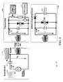
- FIG. 2shows a wireless automotive system, in accordance with another example embodiment of the present invention.
- FIG. 3shows a system and related data flow for transponder authentication and power transmission, in accordance with another example embodiment of the present invention.
- aspects of the present inventionare believed to be applicable to a variety of different types of devices, systems and arrangements for involving transponder-base station coupling and wireless device powering, including those involving automotive applications. While the present invention is not necessarily so limited, various aspects of the invention may be appreciated through a discussion of examples using this context.
- a carrier signal circuitoperates to pass signals with a transponder for wireless communication and power/charging, using a common (e.g., carrier) frequency.
- a common (e.g., carrier) frequencymay involve, for example, immobilizer-type communications and data exchange (e.g., in which a vehicle is immobilized or access thereto is inhibited, absent the presence of a transponder), as well as wireless charging of remote devices.
- a variety of remote wireless devicessuch as hand-held telephones, GPS units, laptop computers, tablets and others can be powered and/or charged via a low frequency (LF) circuit that also operates for data communications with transponders.
- LFlow frequency
- Such a remote devicemay be placed in a charging cradle or platform, to facilitate the transfer of power from the LF circuit.
- a transponderitself may be wirelessly powered/charged via the same LF carrier signal used to send data for vehicle access or engagement.
- wireless power/charging aspects of various embodimentscan be effected without additional hardware relative to transponder-communicating hardware.
- the applicationscan easily be synchronized, since controlled by the common base station.
- a carrier signal circuitoperates to communicate with a remote transponder and to wirelessly power remote devices using a common carrier wave. Communications with the transponder are effected to ensure the presence of the transponder to operating a circuit, such as prior to enabling a vehicle drive system (e.g., for starting an engine or engaging an electric drive system) or prior to activating a circuit that provides access to the vehicle (e.g., unlocks doors). Communications with the transponder can be prioritized over wireless power communications, to ensure timely access to and/or engagement of a vehicle, with a powering/charging application interrupted to effect transponder communications.
- the interruption of the powering/charging applicationis delayed (e.g., momentarily) to allow a powering/charging termination process as may be useful for managing such applications, before switching over to a (prioritized) transponder communication sequence.
- communications with the transpondercan cease and the wireless communications/power circuit can power and/or charge remote devices using the same carrier frequency used with the transponder.
- the wireless communications/power circuitcan power and/or charge remote devices using the same carrier frequency used with the transponder.
- mitigating disturbance between applicationse.g., the wireless power/charge application will not interfere with transponder communications
- additional circuitryas may, for example, be necessary with separate systems.
- the carrier signal circuitis part of a base station in a vehicle
- a transponderis a user-carried device that is used to access the vehicle.
- the base stationcommunicates with the transponder via an antenna.
- the base stationsends a polling signal and the transponder responds to the polling signal (when within range to receive the signal).
- the base stationUpon detection of the response, the base station initiates authentication communications with the transponder.
- the base stationinterrupts wireless power/charging operations to effect the polling signal and further in response to receiving an acknowledgement from the transponder and correspondingly initiating authentication steps.
- the base stationdoes not poll for transponders, and the remote transponder initiates a polling signal.
- Thiscan be effected, for example, in response to a user interacting with the transponder, such as by pressing a button on the transponder or by moving the transponder (e.g., with motion sensing circuitry in the transponder detecting the movement).
- Thiscan also be effected when a user presses a start button in communication with a base station (e.g., within a vehicle, for initiating the ignition of an engine or activation of a battery-powered drive system).
- a receiver at the base stationmonitors for the transponder polling signal, and initiates an authentication sequence in response to detecting a transponder polling signal.
- the base stationprioritizes communications with the transponder, and can otherwise power/charge a remote device. For instance, the base station may power/charge a remote device using a carrier signal having a frequency also used for communicating with the transponder, until a polling signal from the transponder is detected. Upon detecting the polling signal, wireless power/charge signals are stopped and communications are effected with the transponder for authentication. Once communications with the transponder have been appropriately effected (e.g., to unlock the door of a vehicle and/or to enable a vehicle drive system), the base station can resume wireless power/charging operations.
- the base stationmay resume wireless power/charging operations.
- modulesmay be implemented to carry out one or more of the operations and activities described herein and/or shown in the figures.
- a “module”is a circuit that carries out one or more of these or related operations/activities.
- one or more modulesare discrete logic circuits or programmable logic circuits configured and arranged for implementing these operations/activities, as in the circuit modules shown in FIG. 1 .
- the programmable circuitis one or more computer circuits programmed to execute a set (or sets) of instructions (and/or configuration data).
- the instructions (and/or configuration data)can be in the form of firmware or software stored in and accessible from a memory (circuit).
- first and second modulesinclude a combination of a CPU hardware-based circuit and a set of instructions in the form of firmware, where the first module includes a first CPU hardware circuit with one set of instructions and the second module includes a second CPU hardware circuit with another set of instructions.
- Certain embodimentsare directed to a computer program product (e.g., nonvolatile memory device), which includes a machine or computer-readable medium having stored thereon instructions which may be executed by a computer (or other electronic device) to perform these operations/activities.
- a computer program producte.g., nonvolatile memory device
- first and second modulesare implemented to respectively carry out power/communication and authentication.
- the first modulegenerates and transmits a signal to wirelessly charge a portable device in a first operating mode, such as a high-power mode for transmitting a sufficient power for charging such a device (e.g., 5-10W of power).
- a remote transponderWhen a remote transponder is present, such as may be detected via receipt of a signal from the remote transponder, the first module generates and transmits a signal to power and communicate authentication data with the remote transponder in a second mode, such as by communicating data-carrying radio frequency signals.
- These respective modescan be carried out independently from one another, such as to limit the amount of wireless power transmitted to the transponder.
- Another moduleauthenticates the transponder based on communications therewith. For instance, stored authentication data can be accessed and processed with authentication data carried in signals received from the remote transponder via the first module. This authentication can be used to operate a vehicle circuit, such as by operating a starter circuit for engaging a vehicle drive system.
- a signalis generated using high power to power portable devices located near (e.g., within a few millimeters) an antenna driven with the signal.
- This approachmay involve, for example, driving an antenna or an array of antennas on a vehicle dashboard or console on which a portable device such as a mobile phone can be placed for charging.
- this high power levelcan be at a level that exceeds an operating power level of transponders with which the antenna communicates, but that is useful in charging portable devices.
- the signal transmitted to remote transponderscan be effected at a reduced power level at which the transponder operates (e.g., where the high power level may overdrive the transponder, thus).
- the respective power-based approachesfacilitate the use of relatively simple and small transponders (e.g., as larger circuits or power dissipation may be needed for high-power communications), while also providing enough power to operate and/or charge the battery of hand-held devices such as mobile phones, GPS units and computers.
- the respective signalscan be communicated using a common frequency (e.g., a carrier frequency), which also simplifies the base station.
- transponder-based communications for immobilization applicationscan be integrated with wireless charging applications.
- one or more embodimentsmay be implemented with a variety of different types of immobilizer systems or as backup transponder-based communications in PKE or PKG systems.
- methods, systems, base stations or transponders as discussed hereinmay be implemented in a manner similar to and/or in connection with components such as described in U.S. Patent Publication No. 2008/0024322, in U.S. Pat. No. 7,426,275, or in U.S. patent application Ser. No. 13,046,194 entitled “Field Superposition System and Method Therefor,” all of which are fully incorporated herein by reference.
- FIG. 1shows apparatuses and a system 100 for communicating with remote transponders and powering/charging remote devices, in accordance with example embodiments of the present invention.
- the system 100includes a base station 110 and a transponder 120 .
- a power/charging circuit 130that provides power for operating and/or charging a battery in a remote/portable wireless device.
- Each of the base station 110 , transponder 120 and power/charging circuit 130can be implemented separately, in separate embodiments.
- the system 100can be implemented with the base station 110 and the transponder 120 while also interacting with the power/charging circuit 130 .
- the system 100may also be implemented with all three of the base station 110 , transponder 120 and power/charging circuit 130 .
- the transponder 120may be integrated into one or more transponder-based systems, such as immobilizer systems, as may be implemented as a hand-held device that can be carried by an operator (e.g., in a pocket or hand bag).
- the base station 110includes a demodulator 111 , a modulator/transmitter 112 , a capacitive circuit 113 , a control circuit 114 and an antenna 115 .
- the control circuit 114controls the demodulator 111 and modulator/transmitter 112 for communicating signals and transmitting power via the antenna 115 .
- the control circuit 114may be implemented in accordance with one or more embodiments herein, to facilitate both data and power transmission via antenna 115 and using a common carrier frequency, to respectively communicate and power external circuits.
- this power transmissioncan be carried out without interfering with (e.g., prioritized) data communications as may be applicable to vehicle access and drive engagement.
- the transponder 120includes a demodulator 121 that demodulates signals received from the base station 110 via antenna 125 , using the carrier frequency.
- the transponder 120also includes a modulator 122 , which may be implemented to initiate a communication to the base station 110 and therein control the base station to terminate any wireless power applications prior to data communication with the transponder 120 , or otherwise ensure that the powering applications are not carried out or ongoing when the transponder 120 is present (e.g., powering can be resumed after transponder communications have completed).
- the transponder 120may include additional circuits or components, to suit particular needs.
- the power/charging circuit 130also includes an antenna 135 that receives wireless power transmissions from the base station 110 , for powering or charging a battery/load circuit 132 .
- the power-charging circuit 130is also shown with other circuitry (e.g., diodes and a capacitive circuit), but can be implemented using a variety of different types of circuits.
- the base station 110operates to transmit a radio frequency signal having a common or similar carrier frequency (e.g., a 100 kHz carrier, or within about 50 kHz) to both the transponder 120 and the power/charging circuit 130 , and also receives wireless data from the transponder 120 for detecting the presence of and authenticating the transponder. Accordingly, wireless power is transmitted from the base station 110 for operating the power/charging circuit 130 when the circuit is present (e.g., within a field distance of the base station 110 , such as when a user places a mobile device in a cradle or on a surface adjacent a circuit via which the wireless power is transmitted).
- a radio frequency signalhaving a common or similar carrier frequency (e.g., a 100 kHz carrier, or within about 50 kHz)
- a common or similar carrier frequencye.g., a 100 kHz carrier, or within about 50 kHz
- the base station 110Upon detecting the presence of the transponder 120 , the base station 110 communicates with the transponder for authenticating the transponder using the same carrier frequency as used to power the power/charging circuit 130 . If the power/charging circuit 130 is being powered when the transponder 120 is detected (e.g., an operator approaches a vehicle with the transponder 120 ), the transmission of wireless power to the transponder is interrupted and communications with the transponder 120 are carried out.
- control circuit 114includes an interface for communicating over a vehicle bus.
- the base station 110can be coupled to communicate with one or more vehicle activation-type circuits, such as a circuit to open/unlock doors and/or a circuit to operate a drive system such as an engine or battery-powered drive. This approach may be simply to “activate” the respective circuit or circuits with operation of the circuit subsequently carried out.
- the control circuit 114has two modules that operate as follows.
- the first moduleoperates in first and second modes to charge a portable device (e.g., a device having power/charging circuit 130 therein), and to communicate with a remote transponder 120 .
- the first moduleoperates in a first mode to generate and transmit a first signal to wirelessly charge a portable device.
- the first modulealso operates in a second mode to, in response to detecting the presence of the remote transponder 120 , generate and transmit a second signal to power and communicate authentication data with the remote transponder.
- the second moduleauthenticates the transponder 120 by accessing and processing stored authentication data with authentication data carried in signals received from the remote transponder via the first module, and generates an output for activating a transponder-based automotive circuit based upon the authentication.
- the control circuit 114can be connected to a vehicle bus for communicating data over the bus for operating or enabling a vehicle circuit, such as an entry circuit to unlock a door or an ignition circuit for starting an engine.
- the base station 110may include and/or be coupled to one or more antennas for transmitting power and/or data, depending upon the application.
- the antenna 115includes an array of antennas that facilitate the powering of portable devices aligned in different manners (e.g., the array facilitating sufficient power-based transmission contact with the devices under different conditions). The array can be driven at high power to power one or more portable devices, and one or more antennas can be driven in another low-power mode for communicating with a transponder.
- the antenna 115includes a remote antenna, such as a remote antenna near a vehicle door for communicating with an operator-carried transponder. Accordingly, for transponder communications, a single antenna or a subset of antennas may be driven. The respective signals can also be driven at a common or similar carrier frequency.
- FIG. 2shows a wireless automotive system 200 , in accordance with another example embodiment of the present invention.
- the system 200includes a base station 220 within a vehicle 210 , and an antenna 222 connected to the base station.
- the base station 220communicates with a remote transponder 230 for detecting and authenticating the transponder, in response to which a vehicle circuit is activated. Such activation may include, for example, unlocking a vehicle or enabling a vehicle starter or drive system.
- the base station 220includes a transceiver 224 , a controller 226 and a vehicle activation circuit 228 .
- the controller 226controls the transceiver 224 to generate a signal for communicating data with the transponder and for transmitting power to a mobile device.
- the vehicle activation circuit 228generates an output that can be used to permit entry to and/or enable a drive system of the vehicle 210 .
- This vehicle activation circuit 228may, for example, authenticate a transponder 230 and generate a signal in response to the authentication, or may simply pass along data pertaining to authentication communications from the transponder, which can be used by another circuit to authenticate the transponder and enable a vehicle circuit.
- the antenna 222transmits and receives signals for the base station 220 , and further transmits power from the base station to a portable device such as a mobile phone, tablet, gaming device, media playback device or other device.
- a portable devicecan be placed on the console for charging the device.
- a transpondercan be placed on or kept near the console (e.g., in an operator's pocket), in order to activate a circuit to start an engine or otherwise engage a drive system.
- the base station 220also transmits power to the transponder, such as for operating the transponder and/or to charge a battery therein.
- a separate antenna 223is used to communicate with the transponder 230 for effecting access to the vehicle 210 .
- a remote antennamay be located near an entry door near the transponder 230 as shown, and used for communicating data with the transponder 230 for allowing entry to the vehicle. This communication may also be effected to enable a vehicle circuit for operating the vehicle. This approach facilitates access to the antenna, by the transponder 230 , when the transponder has limited range. Moreover, access to the internal antenna 222 may be facilitated at short-range to the transponder, to enable a vehicle once access has been granted.
- the antenna 223may be used to detect the presence of (and authenticate) the transponder 230 near the exterior of the vehicle 210 for unlocking a door
- antenna 222may be used to detect the presence of (and authenticate) the transponder within the vehicle.
- power transmissioncan be effected using a common carrier signal and with priority to transponder communications so as to limit or prevent interference that may occur via power transmission.
- FIG. 3shows a system 300 and related data flow for transponder authentication and power transmission, in accordance with another example embodiment of the present invention.
- the systemincludes a base station 310 , transponder 320 and power/charging circuit 322 .
- the base station 310drives an antenna to send a wake-up signal 330 to the transponder 320 .
- the transponder 320responds with an initiation signal 331 .
- the base station 320does not send the wake-up (e.g., polling) signal, and instead monitors for an initiation signal 331 initiated from the transponder.
- the base stationterminates ongoing power transmission at 332 (if active), and enters into an authentication mode for authenticating the transponder and providing vehicle access.
- authentication communications 333 and 334are respectively sent to and received from transponder 320 . These communications may, for example, also be part of wake-up communications 330 and/or initiation communications 331 .
- the base station 310For authenticated transponders, the base station 310 generates and outputs a vehicle enable signal 335 , as discussed herein.
- datais also communicated between the base station 310 and the power/charging circuit 322 , as shown with data 336 and 337 .
- datamay, for example, involve communications between a mobile telephone that is being charged, and the base station. Such communications may be effected for a variety of applications.
- modules, logic or processing circuitscan be implemented using one or more of: discrete logic circuitry, fully-programmable and semi-programmable circuits such as PLAs (programmable logic arrays), specialized processors or general purpose processors that are specially programmed. Combinations of these and other circuit components are also possible and within the scope of various embodiments, including those discussed above.
- a computing component in a base station as shown in FIG. 1can be implemented in a variety of circuit-based forms, such as through the use of data processing circuit modules.
- Such systemsare exemplified by implementation in high-speed programmable computer/processor circuits, or in combination with discrete and or semi-programmable circuitry (e.g., as Field-Programmable Gate Arrays, Programmable Logic Devices/Arrays).
Landscapes
- Engineering & Computer Science (AREA)
- Computer Networks & Wireless Communication (AREA)
- Power Engineering (AREA)
- Physics & Mathematics (AREA)
- General Physics & Mathematics (AREA)
- Lock And Its Accessories (AREA)
- Charge And Discharge Circuits For Batteries Or The Like (AREA)
- Near-Field Transmission Systems (AREA)
Abstract
Description
Claims (20)
Priority Applications (3)
| Application Number | Priority Date | Filing Date | Title |
|---|---|---|---|
| US13/402,546US9048681B2 (en) | 2012-02-22 | 2012-02-22 | Wireless power and data apparatus, system and method |
| CN201210475865.4ACN103297086B (en) | 2012-02-22 | 2012-11-21 | Wireless power and data equipment, system and method |
| EP13155391.9AEP2631880B1 (en) | 2012-02-22 | 2013-02-15 | Wireless power and data apparatus |
Applications Claiming Priority (1)
| Application Number | Priority Date | Filing Date | Title |
|---|---|---|---|
| US13/402,546US9048681B2 (en) | 2012-02-22 | 2012-02-22 | Wireless power and data apparatus, system and method |
Publications (2)
| Publication Number | Publication Date |
|---|---|
| US20130214732A1 US20130214732A1 (en) | 2013-08-22 |
| US9048681B2true US9048681B2 (en) | 2015-06-02 |
Family
ID=47996996
Family Applications (1)
| Application Number | Title | Priority Date | Filing Date |
|---|---|---|---|
| US13/402,546Active2033-05-03US9048681B2 (en) | 2012-02-22 | 2012-02-22 | Wireless power and data apparatus, system and method |
Country Status (3)
| Country | Link |
|---|---|
| US (1) | US9048681B2 (en) |
| EP (1) | EP2631880B1 (en) |
| CN (1) | CN103297086B (en) |
Cited By (1)
| Publication number | Priority date | Publication date | Assignee | Title |
|---|---|---|---|---|
| US10298065B2 (en) | 2014-05-21 | 2019-05-21 | Intel Corporation | Wireless power transfer with improved device identification and signaling link security |
Families Citing this family (37)
| Publication number | Priority date | Publication date | Assignee | Title |
|---|---|---|---|---|
| TW201344442A (en)* | 2012-04-25 | 2013-11-01 | Hon Hai Prec Ind Co Ltd | Vehicle control system |
| US20140327521A1 (en)* | 2013-05-01 | 2014-11-06 | Qualcomm Incorporated | Asset location using relays |
| US9159224B2 (en) | 2013-09-12 | 2015-10-13 | Nxp B.V. | Wireless power and data apparatus, system and method |
| EP2858258A1 (en)* | 2013-10-07 | 2015-04-08 | Nxp B.V. | Base station for RF communication |
| CN103578169B (en)* | 2013-11-19 | 2016-08-31 | 南京品佳科技开发有限公司 | Intelligent information passive electronic lockset |
| CN103731197B (en)* | 2014-01-17 | 2017-08-11 | 中国联合网络通信集团有限公司 | A kind of radio communication device for supporting energy to transmit and method |
| KR20150130743A (en)* | 2014-05-14 | 2015-11-24 | 삼성전자주식회사 | Ultrasonic probe and ultrasonic diagnostic apparatus |
| CN104113145B (en)* | 2014-07-24 | 2017-01-25 | 杭州柯茂睿海科技有限公司 | Receiving device and method for simultaneously performing radio frequency energy extraction and data communication |
| US9143150B1 (en) | 2014-08-25 | 2015-09-22 | Nxp B.V. | Data communications with analog-to-digital conversion |
| US9374215B2 (en) | 2014-08-25 | 2016-06-21 | Nxp B.V. | Communication synchronization |
| US9160519B1 (en) | 2014-08-25 | 2015-10-13 | Nxp B.V. | Communications with synchronization |
| CN110481360B (en)* | 2014-09-04 | 2023-06-16 | 睿能创意公司 | Charging module of portable electric energy storage device |
| US9543782B2 (en)* | 2014-09-18 | 2017-01-10 | Qualcomm Incorporated | Apparatus and method for lost power detection |
| DE102014225022A1 (en)* | 2014-12-05 | 2016-06-09 | Novero Dabendorf Gmbh | Device and method for controlling an inductive charging device in a vehicle |
| US9775034B2 (en) | 2015-02-06 | 2017-09-26 | Nxp B.V. | Communications with distance authentication |
| US9485609B2 (en) | 2015-02-06 | 2016-11-01 | Nxp B.V. | Pulse frequency control for wireless communications and ranging |
| US9712496B2 (en) | 2015-04-28 | 2017-07-18 | Nxp B.V. | Signal modulation for secure communication |
| US9613475B2 (en) | 2015-05-27 | 2017-04-04 | Nxp B.V. | Communications with interaction detection |
| US10118594B2 (en)* | 2015-08-21 | 2018-11-06 | Honda Motor Co., Ltd. | System and method for reducing power consumption for a smart entry door handle in a vehicle |
| US10328898B2 (en) | 2016-10-12 | 2019-06-25 | Denso International America, Inc. | Passive entry / passive start systems and methods for vehicles |
| US10328899B2 (en) | 2016-10-12 | 2019-06-25 | Denso International America, Inc. | Localization and passive entry / passive start systems and methods for vehicles |
| US11269323B2 (en) | 2018-03-27 | 2022-03-08 | Denso International America, Inc. | Remote park assist message flow systems and methods |
| US11097689B2 (en) | 2018-03-27 | 2021-08-24 | Denso International America, Inc. | Passive entry and passive start system and method using temporary keys |
| US10917784B2 (en) | 2018-03-27 | 2021-02-09 | Denso International America, Inc. | Systems and methods of cloud bonding for vehicles |
| US11548517B2 (en) | 2018-03-28 | 2023-01-10 | Denso International America, Inc. | Activating vehicle functions based on vehicle occupant location |
| US10706651B2 (en) | 2018-03-28 | 2020-07-07 | Denso International America, Inc. | Systems and methods for communication bus security in a vehicle |
| US10839627B2 (en) | 2018-03-28 | 2020-11-17 | Denso International America, Inc. | Reflective environment detection systems and methods |
| US10730479B2 (en) | 2018-03-28 | 2020-08-04 | Denso International America, Inc. | Tamper security systems and methods for vehicles |
| US11330431B2 (en) | 2018-03-28 | 2022-05-10 | Denso International America, Inc. | Targeted advertising with privacy and anti-replay protection |
| CN110525378B (en)* | 2018-05-24 | 2023-06-06 | 法雷奥舒适驾驶助手公司 | PEPS device providing wireless charger resources and method for operating the same |
| CN111431294B (en)* | 2018-12-20 | 2024-12-27 | 法雷奥舒适驾驶助手公司 | Keyless entry and start device providing wireless charger resources and operation method thereof |
| FR3085811A1 (en)* | 2018-09-10 | 2020-03-13 | Psa Automobiles Sa | AUTOMATIC ACCESS AND STARTING SYSTEM FOR A MOTOR VEHICLE AND METHOD FOR MANAGING ACCESS TO A VEHICLE |
| US11689065B2 (en)* | 2019-02-15 | 2023-06-27 | Honda Motor Co., Ltd. | System and methods for charging a device |
| CN112448779B (en)* | 2019-08-29 | 2023-01-03 | 青岛海信移动通信技术股份有限公司 | Intelligent terminal equipment and method for carrying out talkback communication |
| KR102801229B1 (en) | 2019-09-04 | 2025-04-29 | 삼성전자 주식회사 | electronic device and method for authenticating of the same |
| US11527923B2 (en)* | 2020-07-29 | 2022-12-13 | Rivian Ip Holdings, Llc | Bidirectional wireless power transfer with auxiliary devices |
| US11453302B2 (en)* | 2020-07-31 | 2022-09-27 | Ford Global Technologies, Llc | Harvesting electrical energy from an RF signal in a vehicle |
Citations (11)
| Publication number | Priority date | Publication date | Assignee | Title |
|---|---|---|---|---|
| US6275143B1 (en)* | 1997-05-09 | 2001-08-14 | Anatoli Stobbe | Security device having wireless energy transmission |
| US20070176752A1 (en)* | 2005-04-21 | 2007-08-02 | University Of Pittsburgh - Of The Commonwealth System Of Higher Education | Methods and apparatus for reducing power consumption of an active transponder |
| CN101044664A (en) | 2004-06-18 | 2007-09-26 | 捷通国际有限公司 | Vehicle interface |
| US20070279002A1 (en)* | 2006-06-01 | 2007-12-06 | Afshin Partovi | Power source, charging system, and inductive receiver for mobile devices |
| US20080024322A1 (en) | 2003-06-25 | 2008-01-31 | Koninklijke Philips Electronics N.V. | Method and Arrangements for Increasing the Security of Transponder Systems, Particularly for Access to Automobiles |
| US7426275B2 (en) | 2002-10-16 | 2008-09-16 | Alps Electric Co., Ltd | Handling device and method of security data |
| US20100181961A1 (en)* | 2009-01-22 | 2010-07-22 | Qualcomm Incorporated | Adaptive power control for wireless charging |
| WO2010116307A1 (en) | 2009-04-07 | 2010-10-14 | Nxp B.V. | Rfid device being operable in a first and a second operating state |
| CN202144692U (en) | 2011-04-01 | 2012-02-15 | 上海汽车集团股份有限公司 | Automobile no-key entrance and starting system and in-car control device applied to same |
| US20120153894A1 (en)* | 2010-12-16 | 2012-06-21 | Qualcomm Incorporated | Wireless energy transfer and continuous radio station signal coexistence |
| US20120299538A1 (en)* | 2011-05-23 | 2012-11-29 | Hideaki Arai | Vehicle mounted personal device battery charging station and operating methods to avoid interference |
Family Cites Families (6)
| Publication number | Priority date | Publication date | Assignee | Title |
|---|---|---|---|---|
| JPH11168837A (en)* | 1997-10-01 | 1999-06-22 | Casio Comput Co Ltd | Charger for mobile communication equipment |
| JP2008206297A (en)* | 2007-02-20 | 2008-09-04 | Sony Ericsson Mobilecommunications Japan Inc | Portable terminal |
| DE102009031070A1 (en)* | 2009-06-30 | 2011-01-05 | Hella Kgaa Hueck & Co. | Arrangement for loading accumulator in electronic equipment, for example in mobile phone, personal digital assistant or navigation device used in motor vehicle, has controller for keyless entrance system of motor vehicle |
| US20110115605A1 (en)* | 2009-11-17 | 2011-05-19 | Strattec Security Corporation | Energy harvesting system |
| JP5720501B2 (en)* | 2011-08-29 | 2015-05-20 | トヨタ自動車株式会社 | In-vehicle mobile terminal charger |
| US9184598B2 (en)* | 2011-10-26 | 2015-11-10 | Leggett & Platt Canada Co. | Signal discrimination for wireless key fobs and interacting systems |
- 2012
- 2012-02-22USUS13/402,546patent/US9048681B2/enactiveActive
- 2012-11-21CNCN201210475865.4Apatent/CN103297086B/enactiveActive
- 2013
- 2013-02-15EPEP13155391.9Apatent/EP2631880B1/enactiveActive
Patent Citations (15)
| Publication number | Priority date | Publication date | Assignee | Title |
|---|---|---|---|---|
| US6275143B1 (en)* | 1997-05-09 | 2001-08-14 | Anatoli Stobbe | Security device having wireless energy transmission |
| US7612528B2 (en) | 1999-06-21 | 2009-11-03 | Access Business Group International Llc | Vehicle interface |
| US20080001572A9 (en)* | 1999-06-21 | 2008-01-03 | Baarman David W | Vehicle interface |
| US7426275B2 (en) | 2002-10-16 | 2008-09-16 | Alps Electric Co., Ltd | Handling device and method of security data |
| US20080024322A1 (en) | 2003-06-25 | 2008-01-31 | Koninklijke Philips Electronics N.V. | Method and Arrangements for Increasing the Security of Transponder Systems, Particularly for Access to Automobiles |
| CN101044664A (en) | 2004-06-18 | 2007-09-26 | 捷通国际有限公司 | Vehicle interface |
| US20070176752A1 (en)* | 2005-04-21 | 2007-08-02 | University Of Pittsburgh - Of The Commonwealth System Of Higher Education | Methods and apparatus for reducing power consumption of an active transponder |
| US20070279002A1 (en)* | 2006-06-01 | 2007-12-06 | Afshin Partovi | Power source, charging system, and inductive receiver for mobile devices |
| US20100181961A1 (en)* | 2009-01-22 | 2010-07-22 | Qualcomm Incorporated | Adaptive power control for wireless charging |
| CN102292896A (en) | 2009-01-22 | 2011-12-21 | 高通股份有限公司 | Adaptive power control for wireless charging |
| US8823319B2 (en) | 2009-01-22 | 2014-09-02 | Qualcomm Incorporated | Adaptive power control for wireless charging of devices |
| WO2010116307A1 (en) | 2009-04-07 | 2010-10-14 | Nxp B.V. | Rfid device being operable in a first and a second operating state |
| US20120153894A1 (en)* | 2010-12-16 | 2012-06-21 | Qualcomm Incorporated | Wireless energy transfer and continuous radio station signal coexistence |
| CN202144692U (en) | 2011-04-01 | 2012-02-15 | 上海汽车集团股份有限公司 | Automobile no-key entrance and starting system and in-car control device applied to same |
| US20120299538A1 (en)* | 2011-05-23 | 2012-11-29 | Hideaki Arai | Vehicle mounted personal device battery charging station and operating methods to avoid interference |
Cited By (1)
| Publication number | Priority date | Publication date | Assignee | Title |
|---|---|---|---|---|
| US10298065B2 (en) | 2014-05-21 | 2019-05-21 | Intel Corporation | Wireless power transfer with improved device identification and signaling link security |
Also Published As
| Publication number | Publication date |
|---|---|
| CN103297086A (en) | 2013-09-11 |
| US20130214732A1 (en) | 2013-08-22 |
| CN103297086B (en) | 2016-03-16 |
| EP2631880B1 (en) | 2020-07-15 |
| EP2631880A3 (en) | 2016-05-25 |
| EP2631880A2 (en) | 2013-08-28 |
Similar Documents
| Publication | Publication Date | Title |
|---|---|---|
| US9048681B2 (en) | Wireless power and data apparatus, system and method | |
| US10475267B2 (en) | Vehicle finder card with a thin film battery | |
| CN103200657B (en) | Radio communication circuit | |
| KR100573719B1 (en) | Authentication processing system, terminal authentication apparatus, authentication processing method and computer readable medium storing authentication processing program | |
| CN105338486B (en) | Multiband identification and ranging | |
| EP2699044B1 (en) | Wireless data apparatus, system and method | |
| US8798809B2 (en) | System for passive entry and passive start using near field communication | |
| JP5975525B2 (en) | In-vehicle system, vehicle control apparatus, communication control method, and vehicle control method | |
| US11260825B2 (en) | Locking and unlocking system | |
| JP2005005902A (en) | COMMUNICATION DEVICE, PORTABLE TERMINAL DEVICE, COMMUNICATION SYSTEM, COMMUNICATION CONTROL PROGRAM, AND COMMUNICATION CONTROL METHOD | |
| CN114731063A (en) | Wireless charging interference mitigation | |
| US20160236652A1 (en) | Keyless entry system | |
| JP2019153984A (en) | Vehicle control system and vehicle control unit | |
| JP2014225980A (en) | Non-contact charger control system | |
| CN118555555B (en) | Control method and device of vehicle-mounted NFC module and vehicle | |
| CN116061877B (en) | Vehicle passive entry system, handheld terminal and vehicle control system | |
| US9991746B2 (en) | Vehicular system, communication apparatus, power-feeding device, and non-transitory tangible computer-readable storage medium | |
| US20200101940A1 (en) | In-vehicle authentication device and portable device authentication method | |
| US10607429B2 (en) | Onboard device and mobile terminal | |
| KR20140025204A (en) | Wireless communication system for vehicle and control method thereof | |
| KR20210058154A (en) | Wireless charger inside Vehicle | |
| JP2008106577A (en) | Passive keyless entry system | |
| CN110525378B (en) | PEPS device providing wireless charger resources and method for operating the same | |
| CN111431294B (en) | Keyless entry and start device providing wireless charger resources and operation method thereof |
Legal Events
| Date | Code | Title | Description |
|---|---|---|---|
| AS | Assignment | Owner name:NXP B.V., NETHERLANDS Free format text:ASSIGNMENT OF ASSIGNORS INTEREST;ASSIGNOR:NOWOTTNICK, JUERGEN;REEL/FRAME:027745/0673 Effective date:20120215 | |
| STCF | Information on status: patent grant | Free format text:PATENTED CASE | |
| AS | Assignment | Owner name:MORGAN STANLEY SENIOR FUNDING, INC., MARYLAND Free format text:SECURITY AGREEMENT SUPPLEMENT;ASSIGNOR:NXP B.V.;REEL/FRAME:038017/0058 Effective date:20160218 | |
| AS | Assignment | Owner name:MORGAN STANLEY SENIOR FUNDING, INC., MARYLAND Free format text:CORRECTIVE ASSIGNMENT TO CORRECT THE REMOVE APPLICATION 12092129 PREVIOUSLY RECORDED ON REEL 038017 FRAME 0058. ASSIGNOR(S) HEREBY CONFIRMS THE SECURITY AGREEMENT SUPPLEMENT;ASSIGNOR:NXP B.V.;REEL/FRAME:039361/0212 Effective date:20160218 | |
| AS | Assignment | Owner name:MORGAN STANLEY SENIOR FUNDING, INC., MARYLAND Free format text:CORRECTIVE ASSIGNMENT TO CORRECT THE REMOVE APPLICATION 12681366 PREVIOUSLY RECORDED ON REEL 039361 FRAME 0212. ASSIGNOR(S) HEREBY CONFIRMS THE SECURITY AGREEMENT SUPPLEMENT;ASSIGNOR:NXP B.V.;REEL/FRAME:042762/0145 Effective date:20160218 Owner name:MORGAN STANLEY SENIOR FUNDING, INC., MARYLAND Free format text:CORRECTIVE ASSIGNMENT TO CORRECT THE REMOVE APPLICATION 12681366 PREVIOUSLY RECORDED ON REEL 038017 FRAME 0058. ASSIGNOR(S) HEREBY CONFIRMS THE SECURITY AGREEMENT SUPPLEMENT;ASSIGNOR:NXP B.V.;REEL/FRAME:042985/0001 Effective date:20160218 | |
| MAFP | Maintenance fee payment | Free format text:PAYMENT OF MAINTENANCE FEE, 4TH YEAR, LARGE ENTITY (ORIGINAL EVENT CODE: M1551); ENTITY STATUS OF PATENT OWNER: LARGE ENTITY Year of fee payment:4 | |
| AS | Assignment | Owner name:NXP B.V., NETHERLANDS Free format text:RELEASE BY SECURED PARTY;ASSIGNOR:MORGAN STANLEY SENIOR FUNDING, INC.;REEL/FRAME:050745/0001 Effective date:20190903 | |
| AS | Assignment | Owner name:MORGAN STANLEY SENIOR FUNDING, INC., MARYLAND Free format text:CORRECTIVE ASSIGNMENT TO CORRECT THE REMOVE APPLICATION 12298143 PREVIOUSLY RECORDED ON REEL 042985 FRAME 0001. ASSIGNOR(S) HEREBY CONFIRMS THE SECURITY AGREEMENT SUPPLEMENT;ASSIGNOR:NXP B.V.;REEL/FRAME:051029/0001 Effective date:20160218 Owner name:MORGAN STANLEY SENIOR FUNDING, INC., MARYLAND Free format text:CORRECTIVE ASSIGNMENT TO CORRECT THE REMOVE APPLICATION 12298143 PREVIOUSLY RECORDED ON REEL 042762 FRAME 0145. ASSIGNOR(S) HEREBY CONFIRMS THE SECURITY AGREEMENT SUPPLEMENT;ASSIGNOR:NXP B.V.;REEL/FRAME:051145/0184 Effective date:20160218 Owner name:MORGAN STANLEY SENIOR FUNDING, INC., MARYLAND Free format text:CORRECTIVE ASSIGNMENT TO CORRECT THE REMOVE APPLICATION 12298143 PREVIOUSLY RECORDED ON REEL 039361 FRAME 0212. ASSIGNOR(S) HEREBY CONFIRMS THE SECURITY AGREEMENT SUPPLEMENT;ASSIGNOR:NXP B.V.;REEL/FRAME:051029/0387 Effective date:20160218 Owner name:MORGAN STANLEY SENIOR FUNDING, INC., MARYLAND Free format text:CORRECTIVE ASSIGNMENT TO CORRECT THE REMOVE APPLICATION12298143 PREVIOUSLY RECORDED ON REEL 042985 FRAME 0001. ASSIGNOR(S) HEREBY CONFIRMS THE SECURITY AGREEMENT SUPPLEMENT;ASSIGNOR:NXP B.V.;REEL/FRAME:051029/0001 Effective date:20160218 Owner name:MORGAN STANLEY SENIOR FUNDING, INC., MARYLAND Free format text:CORRECTIVE ASSIGNMENT TO CORRECT THE REMOVE APPLICATION12298143 PREVIOUSLY RECORDED ON REEL 039361 FRAME 0212. ASSIGNOR(S) HEREBY CONFIRMS THE SECURITY AGREEMENT SUPPLEMENT;ASSIGNOR:NXP B.V.;REEL/FRAME:051029/0387 Effective date:20160218 Owner name:MORGAN STANLEY SENIOR FUNDING, INC., MARYLAND Free format text:CORRECTIVE ASSIGNMENT TO CORRECT THE REMOVE APPLICATION 12298143 PREVIOUSLY RECORDED ON REEL 038017 FRAME 0058. ASSIGNOR(S) HEREBY CONFIRMS THE SECURITY AGREEMENT SUPPLEMENT;ASSIGNOR:NXP B.V.;REEL/FRAME:051030/0001 Effective date:20160218 Owner name:MORGAN STANLEY SENIOR FUNDING, INC., MARYLAND Free format text:CORRECTIVE ASSIGNMENT TO CORRECT THE REMOVE APPLICATION12298143 PREVIOUSLY RECORDED ON REEL 042762 FRAME 0145. ASSIGNOR(S) HEREBY CONFIRMS THE SECURITY AGREEMENT SUPPLEMENT;ASSIGNOR:NXP B.V.;REEL/FRAME:051145/0184 Effective date:20160218 | |
| MAFP | Maintenance fee payment | Free format text:PAYMENT OF MAINTENANCE FEE, 8TH YEAR, LARGE ENTITY (ORIGINAL EVENT CODE: M1552); ENTITY STATUS OF PATENT OWNER: LARGE ENTITY Year of fee payment:8 |