US9045956B2 - Apparatus and methods utilizing nonexplosive energetic materials for downhole applications - Google Patents
Apparatus and methods utilizing nonexplosive energetic materials for downhole applicationsDownload PDFInfo
- Publication number
- US9045956B2 US9045956B2US13/252,809US201113252809AUS9045956B2US 9045956 B2US9045956 B2US 9045956B2US 201113252809 AUS201113252809 AUS 201113252809AUS 9045956 B2US9045956 B2US 9045956B2
- Authority
- US
- United States
- Prior art keywords
- wellbore
- tool
- energetic material
- battery
- energy
- Prior art date
- Legal status (The legal status is an assumption and is not a legal conclusion. Google has not performed a legal analysis and makes no representation as to the accuracy of the status listed.)
- Active, expires
Links
- 239000000463materialSubstances0.000titleclaimsabstractdescription51
- 238000000034methodMethods0.000titleclaimsabstractdescription18
- 239000002360explosiveSubstances0.000claimsabstractdescription37
- 238000010438heat treatmentMethods0.000claimsdescription36
- 239000002131composite materialSubstances0.000claimsdescription7
- 230000003213activating effectEffects0.000claimsdescription4
- 239000000956alloySubstances0.000claims4
- 229910045601alloyInorganic materials0.000claims4
- 230000003116impacting effectEffects0.000claims1
- 229920005989resinPolymers0.000description7
- 239000011347resinSubstances0.000description7
- 238000007789sealingMethods0.000description5
- 230000015572biosynthetic processEffects0.000description4
- 238000005755formation reactionMethods0.000description4
- 229910000831SteelInorganic materials0.000description3
- 238000004519manufacturing processMethods0.000description3
- 239000010959steelSubstances0.000description3
- NIXOWILDQLNWCW-UHFFFAOYSA-MAcrylateChemical compound[O-]C(=O)C=CNIXOWILDQLNWCW-UHFFFAOYSA-M0.000description2
- -1but not limited toSubstances0.000description2
- 150000001875compoundsChemical class0.000description2
- 239000000945fillerSubstances0.000description2
- 239000012530fluidSubstances0.000description2
- 238000012986modificationMethods0.000description2
- 230000004048modificationEffects0.000description2
- FDYWJVHETVDSRA-UHFFFAOYSA-N1,1-diisocyanatobutaneChemical compoundCCCC(N=C=O)N=C=OFDYWJVHETVDSRA-UHFFFAOYSA-N0.000description1
- UUVUYEVFMFFSMP-UHFFFAOYSA-N2-nitroethyl 2-methylprop-2-enoateChemical compoundCC(=C)C(=O)OCC[N+]([O-])=OUUVUYEVFMFFSMP-UHFFFAOYSA-N0.000description1
- 230000000712assemblyEffects0.000description1
- 238000000429assemblyMethods0.000description1
- IVRMZWNICZWHMI-UHFFFAOYSA-Nazide groupChemical group[N-]=[N+]=[N-]IVRMZWNICZWHMI-UHFFFAOYSA-N0.000description1
- CREMABGTGYGIQB-UHFFFAOYSA-Ncarbon carbonChemical compoundC.CCREMABGTGYGIQB-UHFFFAOYSA-N0.000description1
- 239000011203carbon fibre reinforced carbonSubstances0.000description1
- 238000006243chemical reactionMethods0.000description1
- 239000004020conductorSubstances0.000description1
- 238000004200deflagrationMethods0.000description1
- 238000010586diagramMethods0.000description1
- 125000005442diisocyanate groupChemical group0.000description1
- 238000005553drillingMethods0.000description1
- 229930195733hydrocarbonNatural products0.000description1
- 150000002430hydrocarbonsChemical class0.000description1
- 239000003999initiatorSubstances0.000description1
- 238000003801millingMethods0.000description1
- 239000003129oil wellSubstances0.000description1
- 150000002978peroxidesChemical class0.000description1
- 229920000642polymerPolymers0.000description1
- 229920005862polyolPolymers0.000description1
- 150000003077polyolsChemical class0.000description1
- 150000003254radicalsChemical class0.000description1
- 230000002787reinforcementEffects0.000description1
- 229920001187thermosetting polymerPolymers0.000description1
- 229920002554vinyl polymerPolymers0.000description1
Images


Classifications
- E—FIXED CONSTRUCTIONS
- E21—EARTH OR ROCK DRILLING; MINING
- E21B—EARTH OR ROCK DRILLING; OBTAINING OIL, GAS, WATER, SOLUBLE OR MELTABLE MATERIALS OR A SLURRY OF MINERALS FROM WELLS
- E21B29/00—Cutting or destroying pipes, packers, plugs or wire lines, located in boreholes or wells, e.g. cutting of damaged pipes, of windows; Deforming of pipes in boreholes or wells; Reconditioning of well casings while in the ground
- E21B29/02—Cutting or destroying pipes, packers, plugs or wire lines, located in boreholes or wells, e.g. cutting of damaged pipes, of windows; Deforming of pipes in boreholes or wells; Reconditioning of well casings while in the ground by explosives or by thermal or chemical means
- E—FIXED CONSTRUCTIONS
- E21—EARTH OR ROCK DRILLING; MINING
- E21B—EARTH OR ROCK DRILLING; OBTAINING OIL, GAS, WATER, SOLUBLE OR MELTABLE MATERIALS OR A SLURRY OF MINERALS FROM WELLS
- E21B23/00—Apparatus for displacing, setting, locking, releasing or removing tools, packers or the like in boreholes or wells
- E—FIXED CONSTRUCTIONS
- E21—EARTH OR ROCK DRILLING; MINING
- E21B—EARTH OR ROCK DRILLING; OBTAINING OIL, GAS, WATER, SOLUBLE OR MELTABLE MATERIALS OR A SLURRY OF MINERALS FROM WELLS
- E21B33/00—Sealing or packing boreholes or wells
- E21B33/10—Sealing or packing boreholes or wells in the borehole
- E21B33/12—Packers; Plugs
Definitions
- This disclosurerelates generally to members and devices containing non-explosive energetic material that may be disintegrated downhole.
- Oil wellsare drilled in subsurface formations for the production of hydrocarbons.
- a wellboremay be an open-hole wellbore or a cased-hole wellbore.
- the cased-hole wellincludes a casing (also referred to as “liner”), typically a steel tubular, inside the wellbore. Open holes are not lined with the casing.
- a production stringis installed inside the casing or the open-hole to produce the formation fluids to the surface.
- elements or devicesare placed in the wellbore to perform a function and then are removed from the wellbore. Such devices include, for example, ball/ball seat assemblies, plugs and packers.
- a drilling or milling toolis often conveyed into the wellbore drill or mill the device.
- Such a processrequires a secondary operation that is often complex and time-consuming.
- such devicesmay be formed of a corrodible material that disintegrates over time. In such cases the device to be integrated may remain in the wellbore for a relatively long time period after it has performed its intended function.
- the disclosure hereinprovides devices or articles that include non-explosive energetic materials that may be disintegrated by applying a suitable energy to such devices downhole.
- a method of performing a wellbore operationmay include: providing a device that includes a non-explosive energetic material configured to disintegrate when subjected to a selected energy; placing the device at a selected location in the wellbore to perform a selected function; and subjecting the device to the selected energy to disintegrate the device in the wellbore after the device has performed the selected function.
- an apparatus for use in a wellboremay include a device placed in the wellbore at a selected location, wherein the device includes a non-explosive energetic material configured to disintegrate when subjected to a selected energy, and a source of the selected energy configured to subject the device to the selected energy in the wellbore to disintegrate the device.
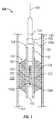
- FIG. 1is a line drawing of an exemplary device placed at selected location in a wellbore that is made at least in part from a non-explosive energetic material and a tool conveyed from the surface to heat the device to disintegrate the device in the wellbore;
- FIG. 2is a line drawing of another exemplary device placed at a selected location in a wellbore that is made at least in part from a non-explosive energetic material and a heating tool that includes a battery and a heating element placed in the wellbore to heat the device to disintegrate the device in the wellbore; and
- FIG. 3is a line drawing of an exemplary device placed at a selected location in a wellbore that is made at least in part from a non-explosive energetic material and an impact tool configured to deflagrate the device by an impact load.
- FIG. 1is a line drawing of an exemplary wellbore system 100 for performing a downhole operation according to one embodiment of the disclosure.
- the system 100includes a wellbore 101 formed in an earth formation 102 .
- the wellbore 101is lined with a casing 105 , such as steel tubing.
- a device 110is placed at selected location 105 a in the casing, which device is intended to be disintegrated after it has performed an intended function in the wellbore 101 .
- the exemplary device 110is a sealing device, such as a packer.
- the device 110includes a mandrel 112 and an expandable sealing member 114 around the mandrel 112 .
- the sealing member 114is shown in an expanded position such that it presses against the inside 105 a of the casing to seal the wellbore above and below the sealing member 114 .
- the mandrel 112 and/or the sealing member 114 or a part of such elementsis formed from a non-explosive energetic material configured to disintegrate when exposed to a selected energy.
- the non-explosive energetic materialwhen exposed to a sufficient amount of the selected energy, it deflagrates, thus causing it to disintegrate over a time period.
- the selected energyis heat.
- the system 100further includes a tool or source 130 configured to expose the device 110 to heat. In the particular embodiment of FIG.
- the tool 130is an electrical tool or device that includes a heating element 132 , such as a coil and an energy source 134 .
- a heating element 132such as a coil and an energy source 134 .
- the source tool 130is conveyed into the wellbore 101 by a suitable conveying member 140 , such as a wireline, tubing or coiled-tubing.
- the tool 130is placed proximate or in contact with the device 110 and activated to supply the electrical energy to the heating element 132 to cause it to produce heat sufficient to heat the device 110 to deflagrate it and thus disintegrate.
- the electrical current to the heating element 132may be provided from the surface via conductors in the conveying member 140 .
- a heating tool 150may be placed in the wellbore proximate to the device 110 .
- the heating tool 150may include a heating element 152 , such as a coil, a battery 154 and a circuit 156 .
- the circuit 156may further include a timer 158 a or a receiver 158 b , each configured to activate the battery to supply electrical energy to the coil 152 .
- the circuit 156activates the battery 154 to supply current to the coil 152 , which generates heat sufficient to deflagrate the device 110 .
- the circuit 156activates the battery 154 in response to a remote signal received by the receiver 158 b .
- the remote signalmay be sent from the surface or another suitable location.
- the remote signalmay be a radio frequency signal, an acoustic signal, an electromagnetic signal or any other suitable signal.
- the remote signalmay be transmitted from a suitable surface location.
- the device tool or sourcemay be an impact tool wherein the device 110 deflagrates when it is subjected to an impact load, which is described in reference to FIG. 3 .
- FIG. 2is a line drawing of an exemplary wellbore system 200 for performing a downhole operation according to another embodiment of the disclosure.
- the system 200includes a wellbore 201 formed in an earth formation 202 .
- the wellbore 201is lined with a casing 205 , such as steel tubing.
- a device 210is placed at selected location 205 a in the casing 205 , which device is intended to be disintegrated after it has performed an intended function in the wellbore 201 .
- the exemplary device 210includes a ball 212 seated on a ball seat 214 in the bore 206 of the casing 205 .
- the ball 212prevents the flow of a fluid 208 through the bore 206 along the downhole direction 207 .
- the ball 212 and/or the ball seat 214 or a part of such elementsis formed from a non-explosive energetic material configured to disintegrate when exposed to a selected energy.
- a non-explosive energetic materialconfigured to disintegrate when exposed to a selected energy.
- the non-explosive energetic materialwhen exposed to a sufficient amount of the selected energy, it deflagrates, thus causing it to disintegrate over a time period.
- the selected energyis heat.
- the system 200further includes a tool or source 230 configured to expose the device 210 to heat.
- the source 230is an electrical tool or device that includes a heating element 232 , such a as a coil, placed proximate to the ball 212 .
- a heating element 232such as a coil
- the source 230further includes a source of electrical energy 234 , such as a battery, that supplies electrical energy (current) to the heating element 232 which generates heat to a selected or desired temperature that is sufficient to cause the non-explosive energetic material to deflagrate.
- the source 230may include an electrical circuit 236 and a timer 238 a or receiver 238 b .
- the timer 238 amay be preset prior to deploying the tool 230 in the wellbore.
- the battery 234may be activated by the circuit in response to receiving a remote signal received by a receiver 238 b .
- the remote signalmay be a radio frequency signal, an acoustic signal, an electromagnetic signal or any other suitable signal.
- the remote signalmay be transmitted from a suitable surface location.
- the batteryactivates when the preset time expires and supplies current to heat the heating element 232 .
- the generated heatheats the non-explosive energetic material in the ball 112 and/or the ball seat 214 to initiate deflagration of such devices.
- the source 230includes a receiver 238 b
- a command signalis sent to the receiver 238 b and the circuit 236 activates the timer or the battery 234 to supply current to the heating element 232 .
- FIG. 3is a line diagram showing a ball 312 and a ball seat 314 in the wellbore that may be deflagated by an impact load.
- an impact tool 320may be conveyed from a surface location by a suitable conveying member 330 to impact the ball 312 with a sufficient force to cause the ball 312 and/or ball seat 314 to deflagrate and thus disintegrate.
- the exemplary embodimentsshow only examples of certain devices for use in wellbores that include non-explosive energetic materials that may be disintegrated downhole. Any device that may utilize non-explosive energetic material may be used for the purposes of this disclosure. Such other device may include, but are not limited to, a plug, sections of a casing, a locking device, a release ring, an o-ring, a support of a retrievable tool, and an anchor member of a retrievable tool.
- the devicemay include an energetic material mixed with a suitable rubber or composite material in a manner that the device is not classified as an explosive so that it may be transported by normal transportation means, such as trucks, and can be handled by operators and deployed into the wellbore. The device will not disintegrate until it is exposed to a selected energy as described hereinabove.
- a device desired to be disintegratedmay be any material combination that includes a non-explosive energetic material so that the device possess initial strength required to perform the intended downhole function and that can then be removed when exposed to a selected energy, such as heat or an impact load.
- the energetic materialmay include an energetic resin and a reinforcement filler.
- the fillermay be any suitable material, including, but not limited to, rubber and a composite material.
- the composite energetic materialsalso have sufficient structural integrity to allow manufacture of structural components.
- the materialcan be deflagrated or detonated upon proper exposure to a selected energy.
- the materialcan act as both a structural component as well as being the explosive device.
- the energetic resinmay be a two-part thermosetting system in which a component A is reacted with a component B to form an energetic resin, and, in some embodiments, the energetic resin may be a one part system.
- One suitable class of energetic resinsare those in which component A includes at least one polymer having two or more azide moieties and a component B that includes at least one polyfunctional compound that has two or more carbon-carbon double or triple bonds adjacent to an activating moiety.
- Another suitable class of resinsinclude those formed by the reaction of component A which includes an energetically substituted alkyl diisocyanate such as those substituted with nitro- or nitraza groups and component B includes a polyol.
- Suitable examples of substituted diisocyanatesinclude, but are not limited to, 3,3,5,7,7-pentanitro-5-aza-1,9-nonane diisocyanate; 2-nitraza-1,4,butane-diisocyanate; 2,5-dinitraza-1,6-hexane diisocyanate; and so forth.
- Another suitable class of energetic resinsinclude those which are a one-part system which employs a free radical cured energetically substituted vinyl compound.
- Such compoundsinclude, but are not limited to, nitroethyl methacrylate, dinitroporpyl acrylate, trinitroethyl acrylate, and so forth. Any suitable initiators known in the art such as peroxides, for example, may be employed. Such material are described in more detail published application 2005/0281968, which is incorporated herein by reference.
Landscapes
- Geology (AREA)
- Life Sciences & Earth Sciences (AREA)
- Engineering & Computer Science (AREA)
- Mining & Mineral Resources (AREA)
- Geochemistry & Mineralogy (AREA)
- Fluid Mechanics (AREA)
- Environmental & Geological Engineering (AREA)
- General Life Sciences & Earth Sciences (AREA)
- Physics & Mathematics (AREA)
- Chemical & Material Sciences (AREA)
- Chemical Kinetics & Catalysis (AREA)
- General Chemical & Material Sciences (AREA)
- Drilling And Exploitation, And Mining Machines And Methods (AREA)
- Processing Of Solid Wastes (AREA)
- Working Measures On Existing Buildindgs (AREA)
- Disintegrating Or Milling (AREA)
Abstract
Description
Claims (22)
Priority Applications (8)
| Application Number | Priority Date | Filing Date | Title |
|---|---|---|---|
| US13/252,809US9045956B2 (en) | 2011-10-04 | 2011-10-04 | Apparatus and methods utilizing nonexplosive energetic materials for downhole applications |
| AU2012318717AAU2012318717B2 (en) | 2011-10-04 | 2012-10-04 | Apparatus and methods utilizing nonexplosive energetic materials for downhole applications |
| BR112014007515ABR112014007515A2 (en) | 2011-10-04 | 2012-10-04 | apparatus and methods using non-explosive energy materials for downhole applications |
| EP12838692.7AEP2764204A1 (en) | 2011-10-04 | 2012-10-04 | Apparatus and methods utilizing nonexplosive energetic materials for downhole applications |
| CA2848423ACA2848423C (en) | 2011-10-04 | 2012-10-04 | Apparatus and methods utilizing nonexplosive energetic materials for downhole applications |
| AP2014007525AAP2014007525A0 (en) | 2011-10-04 | 2012-10-04 | Apparatus and methods utilizing nonexplosive energetic materials for downhole applications |
| PCT/US2012/058600WO2013052573A1 (en) | 2011-10-04 | 2012-10-04 | Apparatus and methods utilizing nonexplosive energetic materials for downhole applications |
| CN201280047062.7ACN103827440B (en) | 2011-10-04 | 2012-10-04 | Utilize the apparatus and method for down-hole application of non-explosivity high energy material |
Applications Claiming Priority (1)
| Application Number | Priority Date | Filing Date | Title |
|---|---|---|---|
| US13/252,809US9045956B2 (en) | 2011-10-04 | 2011-10-04 | Apparatus and methods utilizing nonexplosive energetic materials for downhole applications |
Publications (2)
| Publication Number | Publication Date |
|---|---|
| US20130081825A1 US20130081825A1 (en) | 2013-04-04 |
| US9045956B2true US9045956B2 (en) | 2015-06-02 |
Family
ID=47991541
Family Applications (1)
| Application Number | Title | Priority Date | Filing Date |
|---|---|---|---|
| US13/252,809Active2033-02-04US9045956B2 (en) | 2011-10-04 | 2011-10-04 | Apparatus and methods utilizing nonexplosive energetic materials for downhole applications |
Country Status (8)
| Country | Link |
|---|---|
| US (1) | US9045956B2 (en) |
| EP (1) | EP2764204A1 (en) |
| CN (1) | CN103827440B (en) |
| AP (1) | AP2014007525A0 (en) |
| AU (1) | AU2012318717B2 (en) |
| BR (1) | BR112014007515A2 (en) |
| CA (1) | CA2848423C (en) |
| WO (1) | WO2013052573A1 (en) |
Families Citing this family (18)
| Publication number | Priority date | Publication date | Assignee | Title |
|---|---|---|---|---|
| GB201416720D0 (en)* | 2014-09-22 | 2014-11-05 | Spex Services Ltd | Improved Plug |
| US10408012B2 (en) | 2015-07-24 | 2019-09-10 | Innovex Downhole Solutions, Inc. | Downhole tool with an expandable sleeve |
| US10156119B2 (en) | 2015-07-24 | 2018-12-18 | Innovex Downhole Solutions, Inc. | Downhole tool with an expandable sleeve |
| CN106481304A (en)* | 2016-12-12 | 2017-03-08 | 中国石油化工股份有限公司江汉油田分公司石油工程技术研究院 | A kind of built-in remote-control is hung fire the quickly degradable ball of device |
| US10227842B2 (en) | 2016-12-14 | 2019-03-12 | Innovex Downhole Solutions, Inc. | Friction-lock frac plug |
| US10865617B2 (en) | 2016-12-20 | 2020-12-15 | Baker Hughes, A Ge Company, Llc | One-way energy retention device, method and system |
| US10364630B2 (en)* | 2016-12-20 | 2019-07-30 | Baker Hughes, A Ge Company, Llc | Downhole assembly including degradable-on-demand material and method to degrade downhole tool |
| US10450840B2 (en) | 2016-12-20 | 2019-10-22 | Baker Hughes, A Ge Company, Llc | Multifunctional downhole tools |
| US10364631B2 (en)* | 2016-12-20 | 2019-07-30 | Baker Hughes, A Ge Company, Llc | Downhole assembly including degradable-on-demand material and method to degrade downhole tool |
| US10364632B2 (en)* | 2016-12-20 | 2019-07-30 | Baker Hughes, A Ge Company, Llc | Downhole assembly including degradable-on-demand material and method to degrade downhole tool |
| US11015409B2 (en)* | 2017-09-08 | 2021-05-25 | Baker Hughes, A Ge Company, Llc | System for degrading structure using mechanical impact and method |
| US10989016B2 (en) | 2018-08-30 | 2021-04-27 | Innovex Downhole Solutions, Inc. | Downhole tool with an expandable sleeve, grit material, and button inserts |
| US11125039B2 (en) | 2018-11-09 | 2021-09-21 | Innovex Downhole Solutions, Inc. | Deformable downhole tool with dissolvable element and brittle protective layer |
| US11965391B2 (en) | 2018-11-30 | 2024-04-23 | Innovex Downhole Solutions, Inc. | Downhole tool with sealing ring |
| US11396787B2 (en) | 2019-02-11 | 2022-07-26 | Innovex Downhole Solutions, Inc. | Downhole tool with ball-in-place setting assembly and asymmetric sleeve |
| US11261683B2 (en) | 2019-03-01 | 2022-03-01 | Innovex Downhole Solutions, Inc. | Downhole tool with sleeve and slip |
| US11203913B2 (en) | 2019-03-15 | 2021-12-21 | Innovex Downhole Solutions, Inc. | Downhole tool and methods |
| US11572753B2 (en) | 2020-02-18 | 2023-02-07 | Innovex Downhole Solutions, Inc. | Downhole tool with an acid pill |
Citations (6)
| Publication number | Priority date | Publication date | Assignee | Title |
|---|---|---|---|---|
| US2771140A (en)* | 1953-08-28 | 1956-11-20 | Socony Mobil Oil Co Inc | Subsurface igniter |
| US5540293A (en)* | 1995-02-21 | 1996-07-30 | The Mohaupt Family Trust | Firing Head |
| US20050281968A1 (en) | 2004-06-16 | 2005-12-22 | Alliant Techsystems Inc. | Energetic structural material |
| US20070284114A1 (en)* | 2006-06-08 | 2007-12-13 | Halliburton Energy Services, Inc. | Method for removing a consumable downhole tool |
| US20080202764A1 (en)* | 2007-02-22 | 2008-08-28 | Halliburton Energy Services, Inc. | Consumable downhole tools |
| US20100175867A1 (en)* | 2009-01-14 | 2010-07-15 | Halliburton Energy Services, Inc. | Well Tools Incorporating Valves Operable by Low Electrical Power Input |
Family Cites Families (5)
| Publication number | Priority date | Publication date | Assignee | Title |
|---|---|---|---|---|
| US5607017A (en)* | 1995-07-03 | 1997-03-04 | Pes, Inc. | Dissolvable well plug |
| NO20001801L (en)* | 2000-04-07 | 2001-10-08 | Total Catcher Offshore As | Device by test plug |
| GB2428264B (en)* | 2004-03-12 | 2008-07-30 | Schlumberger Holdings | Sealing system and method for use in a well |
| US7350582B2 (en)* | 2004-12-21 | 2008-04-01 | Weatherford/Lamb, Inc. | Wellbore tool with disintegratable components and method of controlling flow |
| CN102094613A (en)* | 2010-12-29 | 2011-06-15 | 西安通源石油科技股份有限公司 | Composite perforating method and device carrying support agent |
- 2011
- 2011-10-04USUS13/252,809patent/US9045956B2/enactiveActive
- 2012
- 2012-10-04APAP2014007525Apatent/AP2014007525A0/enunknown
- 2012-10-04CACA2848423Apatent/CA2848423C/enactiveActive
- 2012-10-04BRBR112014007515Apatent/BR112014007515A2/ennot_activeApplication Discontinuation
- 2012-10-04CNCN201280047062.7Apatent/CN103827440B/enactiveActive
- 2012-10-04EPEP12838692.7Apatent/EP2764204A1/ennot_activeWithdrawn
- 2012-10-04WOPCT/US2012/058600patent/WO2013052573A1/enactiveApplication Filing
- 2012-10-04AUAU2012318717Apatent/AU2012318717B2/ennot_activeCeased
Patent Citations (6)
| Publication number | Priority date | Publication date | Assignee | Title |
|---|---|---|---|---|
| US2771140A (en)* | 1953-08-28 | 1956-11-20 | Socony Mobil Oil Co Inc | Subsurface igniter |
| US5540293A (en)* | 1995-02-21 | 1996-07-30 | The Mohaupt Family Trust | Firing Head |
| US20050281968A1 (en) | 2004-06-16 | 2005-12-22 | Alliant Techsystems Inc. | Energetic structural material |
| US20070284114A1 (en)* | 2006-06-08 | 2007-12-13 | Halliburton Energy Services, Inc. | Method for removing a consumable downhole tool |
| US20080202764A1 (en)* | 2007-02-22 | 2008-08-28 | Halliburton Energy Services, Inc. | Consumable downhole tools |
| US20100175867A1 (en)* | 2009-01-14 | 2010-07-15 | Halliburton Energy Services, Inc. | Well Tools Incorporating Valves Operable by Low Electrical Power Input |
Also Published As
| Publication number | Publication date |
|---|---|
| WO2013052573A1 (en) | 2013-04-11 |
| BR112014007515A2 (en) | 2017-04-04 |
| CN103827440B (en) | 2017-09-15 |
| EP2764204A1 (en) | 2014-08-13 |
| CA2848423A1 (en) | 2013-04-11 |
| AU2012318717B2 (en) | 2016-05-12 |
| AP2014007525A0 (en) | 2014-03-31 |
| CN103827440A (en) | 2014-05-28 |
| AU2012318717A1 (en) | 2014-03-06 |
| US20130081825A1 (en) | 2013-04-04 |
| CA2848423C (en) | 2016-06-28 |
Similar Documents
| Publication | Publication Date | Title |
|---|---|---|
| US9045956B2 (en) | Apparatus and methods utilizing nonexplosive energetic materials for downhole applications | |
| US20230203916A1 (en) | In situ expandable tubulars | |
| US11585188B2 (en) | In situ expandable tubulars | |
| US9822609B2 (en) | Well tools operable via thermal expansion resulting from reactive materials | |
| US11555378B2 (en) | Self-destructible frac ball enclosed within a destructible ball retainer | |
| US7779926B2 (en) | Wellbore plug adapter kit and method of using thereof | |
| US20150330200A1 (en) | Apparatus and Method for Operating a Device in a Wellbore Using Signals Generated in Response to Strain on a Downhole Member | |
| US10378345B2 (en) | Capsules containing micro-proppant and a substance to produce micro-seismic events | |
| WO2018102196A1 (en) | In situ expandable tubulars | |
| CN106795746A (en) | Wellbore plug isolation system and method | |
| CN103534436A (en) | Autonomous downhole conveyance system | |
| US20200308946A1 (en) | Well stimulation apparatus and a method of use thereof | |
| WO2017127075A1 (en) | Retaining sealing element of wellbore isolation device with slip elements | |
| US11028673B2 (en) | Thru-tubing operations | |
| CA3054380A1 (en) | Perforation tool and methods of use | |
| US20230175345A1 (en) | Method and Apparatus for a plug with a shear landing feature for untethered object | |
| US12247458B2 (en) | Method and apparatus for providing a ball-in-place plug activated by cup and internal continuous expansion mechanism | |
| US12366135B2 (en) | Method and apparatus for a plug including a radial and collapsible gap within the continuous expandable sealing ring | |
| AU2014201719B2 (en) | Well tools operable via thermal expansion resulting from reactive materials |
Legal Events
| Date | Code | Title | Description |
|---|---|---|---|
| AS | Assignment | Owner name:BAKER HUGHES INCORPORATED, TEXAS Free format text:ASSIGNMENT OF ASSIGNORS INTEREST;ASSIGNORS:LYNDE, GERALD D.;XU, YANG;RICHARD, BENNETT M.;AND OTHERS;SIGNING DATES FROM 20111005 TO 20111024;REEL/FRAME:027110/0264 | |
| STCF | Information on status: patent grant | Free format text:PATENTED CASE | |
| MAFP | Maintenance fee payment | Free format text:PAYMENT OF MAINTENANCE FEE, 4TH YEAR, LARGE ENTITY (ORIGINAL EVENT CODE: M1551); ENTITY STATUS OF PATENT OWNER: LARGE ENTITY Year of fee payment:4 | |
| AS | Assignment | Owner name:BAKER HUGHES, A GE COMPANY, LLC, TEXAS Free format text:CHANGE OF NAME;ASSIGNOR:BAKER HUGHES INCORPORATED;REEL/FRAME:059480/0512 Effective date:20170703 | |
| AS | Assignment | Owner name:BAKER HUGHES HOLDINGS LLC, TEXAS Free format text:CHANGE OF NAME;ASSIGNOR:BAKER HUGHES, A GE COMPANY, LLC;REEL/FRAME:059595/0759 Effective date:20200413 | |
| MAFP | Maintenance fee payment | Free format text:PAYMENT OF MAINTENANCE FEE, 8TH YEAR, LARGE ENTITY (ORIGINAL EVENT CODE: M1552); ENTITY STATUS OF PATENT OWNER: LARGE ENTITY Year of fee payment:8 |