US9045189B2 - Scooter assemblies - Google Patents
Scooter assembliesDownload PDFInfo
- Publication number
- US9045189B2 US9045189B2US14/043,625US201314043625AUS9045189B2US 9045189 B2US9045189 B2US 9045189B2US 201314043625 AUS201314043625 AUS 201314043625AUS 9045189 B2US9045189 B2US 9045189B2
- Authority
- US
- United States
- Prior art keywords
- scooter
- foot brake
- deck
- assembly
- neck
- Prior art date
- Legal status (The legal status is an assumption and is not a legal conclusion. Google has not performed a legal analysis and makes no representation as to the accuracy of the status listed.)
- Expired - Fee Related
Links
Images


Classifications
- B—PERFORMING OPERATIONS; TRANSPORTING
- B62—LAND VEHICLES FOR TRAVELLING OTHERWISE THAN ON RAILS
- B62J—CYCLE SADDLES OR SEATS; AUXILIARY DEVICES OR ACCESSORIES SPECIALLY ADAPTED TO CYCLES AND NOT OTHERWISE PROVIDED FOR, e.g. ARTICLE CARRIERS OR CYCLE PROTECTORS
- B62J43/00—Arrangements of batteries
- B62J43/20—Arrangements of batteries characterised by the mounting
- B62J43/28—Arrangements of batteries characterised by the mounting hidden within the cycle frame
- B—PERFORMING OPERATIONS; TRANSPORTING
- B62—LAND VEHICLES FOR TRAVELLING OTHERWISE THAN ON RAILS
- B62J—CYCLE SADDLES OR SEATS; AUXILIARY DEVICES OR ACCESSORIES SPECIALLY ADAPTED TO CYCLES AND NOT OTHERWISE PROVIDED FOR, e.g. ARTICLE CARRIERS OR CYCLE PROTECTORS
- B62J43/00—Arrangements of batteries
- B62J43/10—Arrangements of batteries for propulsion
- B62J43/16—Arrangements of batteries for propulsion on motorcycles or the like
- B—PERFORMING OPERATIONS; TRANSPORTING
- B62—LAND VEHICLES FOR TRAVELLING OTHERWISE THAN ON RAILS
- B62K—CYCLES; CYCLE FRAMES; CYCLE STEERING DEVICES; RIDER-OPERATED TERMINAL CONTROLS SPECIALLY ADAPTED FOR CYCLES; CYCLE AXLE SUSPENSIONS; CYCLE SIDE-CARS, FORECARS, OR THE LIKE
- B62K11/00—Motorcycles, engine-assisted cycles or motor scooters with one or two wheels
- B—PERFORMING OPERATIONS; TRANSPORTING
- B62—LAND VEHICLES FOR TRAVELLING OTHERWISE THAN ON RAILS
- B62K—CYCLES; CYCLE FRAMES; CYCLE STEERING DEVICES; RIDER-OPERATED TERMINAL CONTROLS SPECIALLY ADAPTED FOR CYCLES; CYCLE AXLE SUSPENSIONS; CYCLE SIDE-CARS, FORECARS, OR THE LIKE
- B62K21/00—Steering devices
- B62K21/12—Handlebars; Handlebar stems
- B—PERFORMING OPERATIONS; TRANSPORTING
- B62—LAND VEHICLES FOR TRAVELLING OTHERWISE THAN ON RAILS
- B62K—CYCLES; CYCLE FRAMES; CYCLE STEERING DEVICES; RIDER-OPERATED TERMINAL CONTROLS SPECIALLY ADAPTED FOR CYCLES; CYCLE AXLE SUSPENSIONS; CYCLE SIDE-CARS, FORECARS, OR THE LIKE
- B62K3/00—Bicycles
- B62K3/002—Bicycles without a seat, i.e. the rider operating the vehicle in a standing position, e.g. non-motorized scooters; non-motorized scooters with skis or runners
- B—PERFORMING OPERATIONS; TRANSPORTING
- B62—LAND VEHICLES FOR TRAVELLING OTHERWISE THAN ON RAILS
- B62L—BRAKES SPECIALLY ADAPTED FOR CYCLES
- B62L1/00—Brakes; Arrangements thereof
- B62L1/02—Brakes; Arrangements thereof in which cycle wheels are engaged by brake elements
- B62L1/04—Brakes; Arrangements thereof in which cycle wheels are engaged by brake elements the tyre surfaces being engaged
- B—PERFORMING OPERATIONS; TRANSPORTING
- B62—LAND VEHICLES FOR TRAVELLING OTHERWISE THAN ON RAILS
- B62M—RIDER PROPULSION OF WHEELED VEHICLES OR SLEDGES; POWERED PROPULSION OF SLEDGES OR SINGLE-TRACK CYCLES; TRANSMISSIONS SPECIALLY ADAPTED FOR SUCH VEHICLES
- B62M6/00—Rider propulsion of wheeled vehicles with additional source of power, e.g. combustion engine or electric motor
- B62M6/80—Accessories, e.g. power sources; Arrangements thereof
- B62M6/90—Batteries
- B—PERFORMING OPERATIONS; TRANSPORTING
- B62—LAND VEHICLES FOR TRAVELLING OTHERWISE THAN ON RAILS
- B62J—CYCLE SADDLES OR SEATS; AUXILIARY DEVICES OR ACCESSORIES SPECIALLY ADAPTED TO CYCLES AND NOT OTHERWISE PROVIDED FOR, e.g. ARTICLE CARRIERS OR CYCLE PROTECTORS
- B62J43/00—Arrangements of batteries
- B—PERFORMING OPERATIONS; TRANSPORTING
- B62—LAND VEHICLES FOR TRAVELLING OTHERWISE THAN ON RAILS
- B62K—CYCLES; CYCLE FRAMES; CYCLE STEERING DEVICES; RIDER-OPERATED TERMINAL CONTROLS SPECIALLY ADAPTED FOR CYCLES; CYCLE AXLE SUSPENSIONS; CYCLE SIDE-CARS, FORECARS, OR THE LIKE
- B62K2202/00—Motorised scooters
- B—PERFORMING OPERATIONS; TRANSPORTING
- B62—LAND VEHICLES FOR TRAVELLING OTHERWISE THAN ON RAILS
- B62K—CYCLES; CYCLE FRAMES; CYCLE STEERING DEVICES; RIDER-OPERATED TERMINAL CONTROLS SPECIALLY ADAPTED FOR CYCLES; CYCLE AXLE SUSPENSIONS; CYCLE SIDE-CARS, FORECARS, OR THE LIKE
- B62K2204/00—Adaptations for driving cycles by electric motor
- B—PERFORMING OPERATIONS; TRANSPORTING
- B62—LAND VEHICLES FOR TRAVELLING OTHERWISE THAN ON RAILS
- B62M—RIDER PROPULSION OF WHEELED VEHICLES OR SLEDGES; POWERED PROPULSION OF SLEDGES OR SINGLE-TRACK CYCLES; TRANSMISSIONS SPECIALLY ADAPTED FOR SUCH VEHICLES
- B62M6/00—Rider propulsion of wheeled vehicles with additional source of power, e.g. combustion engine or electric motor
- B62M6/40—Rider propelled cycles with auxiliary electric motor
- B62M6/60—Rider propelled cycles with auxiliary electric motor power-driven at axle parts
- B—PERFORMING OPERATIONS; TRANSPORTING
- B62—LAND VEHICLES FOR TRAVELLING OTHERWISE THAN ON RAILS
- B62M—RIDER PROPULSION OF WHEELED VEHICLES OR SLEDGES; POWERED PROPULSION OF SLEDGES OR SINGLE-TRACK CYCLES; TRANSMISSIONS SPECIALLY ADAPTED FOR SUCH VEHICLES
- B62M7/00—Motorcycles characterised by position of motor or engine
- B62M7/12—Motorcycles characterised by position of motor or engine with the engine beside or within the driven wheel
Definitions
- the inventions disclosed hereinrelate generally to scooter assemblies.
- a scootercomprises a deck configured to support a rider; a front wheel and a rear wheel; a steering column comprising a steering tube and a handlebar assembly, the steering column configured to steer the scooter by controlling a direction of the front wheel; and a foot brake, wherein the foot brake is configured to apply a braking force to the rear wheel when the foot brake is pressed down.
- the foot brakeis further configured to rotate about a pivot axis when the foot brake is pressed down.
- the foot brakecan be further configured to return to its un-pivoted position when the foot brake is no longer pressed down.
- a rear portion of the deckcomprises the foot brake.
- the foot brake and the deckare separate.
- the foot brakecan comprise a plurality of ridges configured to enhance a traction of the foot brake.
- the foot brakecomprises plastic. In other embodiments, the foot brake comprises metal.
- a method of operating a scootercomprises pressing down on a foot brake to apply a braking force to a rear wheel.
- the methodcan further comprise identifying a location of the foot brake by sensing a plurality of ridges on the foot brake.
- a scootercomprises a deck configured to support a rider; a front wheel and a rear wheel; a head tube; and a steering column supported for rotation relative to the head tube and comprising a steering tube and a handlebar assembly, the steering column configured to steer the scooter by controlling a direction of the front wheel; the scooter further comprises a plurality of neck members that couple the head tube to the deck.
- the plurality of neck membersare coupled to the deck at spaced lateral locations.
- two neck membersare provided and are vertically stacked relative to one another.
- three neck membersare provided, with two extending laterally and one being centrally positioned.
- the plurality of neck membersare coupled to one or the other of an upper base section and a lower base section, which receive a portion of the deck between them.
- a scootercomprises a frame configured to support a rider; a front wheel and a rear wheel connected to the frame; a steering column supported for rotation relative to the frame and comprising a steering tube and a handlebar assembly, the steering column configured to steer the scooter by controlling a direction of the front wheel; the scooter further comprises a fork assembly that couples the front wheel to the steering tube, wherein the fork assembly includes a structural fork member and a cover, which surrounds a portion of the structural fork member.
- the covercomprises one or both of a front surface and a rear surface, which preferably closely follow a contour of the front wheel.
- the covercomprises a first portion and a second portion, which can be provided on respective first and second sides of the structural fork member.
- the covercan comprise an opening on each side, which exposes a portion of the structural fork member.
- a scootercomprises a frame configured to support a rider; a front wheel and a rear wheel connected to the frame; a steering column supported for rotation relative to the frame and comprising a steering tube and a handlebar assembly, the steering column configured to steer the scooter by controlling a direction of the front wheel; the scooter further comprises a clamp for the steering column, which comprises at least three clamping sections, wherein each clamping section includes a clamp bolt. In some configurations, the clamp includes four clamping sections.
- a scootercomprises a frame assembly comprising a deck configured to support a rider; a front wheel and a rear wheel connected to the frame; a steering column supported for rotation relative to the frame and comprising a steering tube and a handlebar assembly, the steering column configured to steer the scooter by controlling a direction of the front wheel; the scooter further comprises a bash guard coupled to the frame assembly and extending toward the front wheel at a location below the deck.
- the bash guardincludes a lower planar portion and a front planar portion. The lower planar portion can be substantially parallel with the deck and the front planar portion can be angled with an upper edge closer to the front wheel than a lower edge.
- the bash guardcomprises a plurality of openings.
- a scootercomprises a frame configured to support a rider; a front wheel and a rear wheel connected to the frame; a steering column supported for rotation relative to the frame and comprising a steering tube and a handlebar assembly, the steering column configured to steer the scooter by controlling a direction of the front wheel; the scooter further comprises a deck supported on the frame, wherein the deck has a first portion and a second portion.
- the first portionis constructed from a first material and the second portion is constructed from a second material.
- the materialsmay be plastic and metal, respectively.
- second portioncomprises a plurality of openings.
- a grip layercan be positioned underneath the second portion and the material of the grip layer can protrude through the plurality of openings of the second portion.
- the first portion and the second portionhave different frictional properties. In such configurations, the first portion and the second portion can be the same material or different materials.
- FIG. 1a right side view of a portion of an embodiment of a scooter assembly.
- FIG. 2is a perspective view of another portion of the scooter assembly of FIG. 1 .
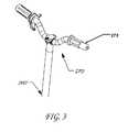
- FIG. 3is a perspective view of a handlebar assembly of the scooter assembly of FIG. 1 , with portions of one of the handlebar sections cut-away to show underlying structure.
- FIG. 4is a perspective view of another portion of the scooter assembly of FIG. 1 , with portions of a steering column cut away to reveal underlying structure.
- FIG. 5is a view of a removable portion of the scooter assembly of FIG. 1 containing one or more batteries removed from the scooter and positioned in a charging device.
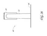
- FIG. 6is a top view of an embodiment of a foot brake of the scooter assembly of FIG. 1 separate from the scooter assembly.
- FIG. 7is a left side view of the scooter assembly of FIG. 1 .
- FIG. 8is a perspective view of a rear portion of the scooter assembly of FIG. 1 .
- FIG. 9is another perspective view of a rear portion of the scooter assembly of FIG. 1 .
- FIG. 10is a left side view of a rear portion of the scooter assembly of FIG. 1 .
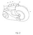
- FIG. 11is another perspective view of a rear portion of the scooter assembly of FIG. 1 .
- FIG. 12is a perspective view of an embodiment of a scooter frame assembly.
- FIG. 13is a top view of the scooter frame assembly of FIG. 12 .
- FIG. 14is another perspective view of the scooter frame assembly of FIG. 12 .
- FIG. 15is a right side view of the scooter frame assembly of FIG. 12 .
- FIG. 16is a perspective view of an embodiment of a scooter neck section.
- FIG. 17is a top view of the scooter neck section of FIG. 16 .
- FIG. 18is a front view of the scooter neck section of FIG. 16 .
- FIG. 19is a right side view of the scooter neck section of FIG. 16 .
- FIG. 20is a rear view of the scooter neck section of FIG. 16 .
- FIG. 21is a bottom view of the scooter neck section of FIG. 16 .
- FIG. 22is a perspective view of another embodiment of a scooter neck section.
- FIG. 23is a left side view of a lower-front portion of an embodiment of a scooter assembly.
- FIG. 24is a perspective view of an embodiment of a scooter neck section.
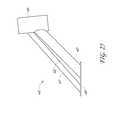
- FIG. 25is a left side view of the scooter neck section of FIG. 24 .
- FIG. 26is a rear view of the scooter neck section of FIG. 24 .
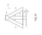
- FIG. 27is a front view of the scooter neck section of FIG. 24 .
- FIG. 28is a top view of the scooter neck section of FIG. 24 .
- FIG. 29is a left side view of a portion of an embodiment of a scooter assembly comprising a clamp assembly.
- FIG. 30is a perspective view of the portion of the scooter assembly of FIG. 29 .
- FIG. 31is a left side view of a portion of an embodiment of a scooter assembly comprising a clamp assembly.
- FIG. 32is a perspective view of the portion of the scooter assembly of FIG. 31 .
- FIG. 33is a perspective view of a portion of an embodiment of a scooter assembly comprising a front fork.
- FIG. 34is a left side view of the portion of the scooter assembly of FIG. 33 .
- FIG. 35is another left side view of the portion of the scooter assembly of FIG. 33 .
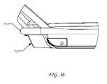
- FIG. 36is a side view of a portion of an embodiment of a scooter assembly comprising a bash guard.
- FIG. 37is a perspective view of a bottom of the scooter assembly comprising a bash guard of FIG. 36 .
- FIG. 38is a perspective view of an embodiment of a deck assembly for a scooter assembly.
- FIG. 39is a top view of another embodiment of a deck assembly for a scooter assembly.
- FIGS. 1-11generally relate to embodiments related to scooters comprising a deck, front and rear wheels, and a foot brake, wherein the foot brake is in proximity to the rear of the deck and can apply a braking force to the rear wheel.
- FIGS. 1-11also generally relate to embodiments related electric scooters comprising a frame comprising tubular members, wherein batteries can be located within the tubular members.
- FIG. 1shows a side view of an embodiment of a scooter assembly 200 that comprises a deck 210 , a neck 220 , a head tube 224 , a clamp assembly 250 , a steering tube 260 , a front wheel 230 , a rear wheel 234 , and a foot brake 240 .
- the scooter assembly 200can be an electric scooter.
- the neck 220can be joined to the deck 210 at or near a front end 212 of the deck 210 .
- the deck 210is a component of the scooter assembly 200 on which a rider can stand during use.
- the neck 220can serve to connect the deck 210 to the front wheel and the handlebar assemblies.
- the neck 220can be coupled to the deck 210 .
- the head tube 224can be fixedly attached to the neck 220 .
- the neck 220 and head tube 224can be may be made of various metals, plastic, carbon fiber, or other materials that impart sufficient structural strength.
- the steering tube 260can extend through the head tube 224 and be rotatable relative thereto.
- a handlebar assembly(not shown) can be attached.
- the handlebar assemblycan comprise a left handle and a right handle for the rider to grip and steer the scooter 200 .
- Turning the handlebar assemblycan cause the steering tube 260 to turn the front wheel 230 .
- a front fork 232can be coupled to a bottom portion of the steering tube 260 and can rotatably support the front wheel 230 .
- the rear wheel 234can be a fixed position wheel.
- the rear wheel 234can be configured to rotate about a rear-wheel axle 236 .
- the foot brake 240can be attached in proximity to a rear portion 214 of the deck 210 .
- the foot brake 240can comprise a plurality of ridges 244 to enhance traction of the foot brake 240 and facilitate location of the foot brake 240 by a rider.
- the foot brake 240can comprise plastic.
- the foot brake 240can comprise metals, carbon fiber, or any other suitable material.
- the foot brake 240can be configured to pivot about a pivot axis 242 . By pivoting downward, the foot brake 240 can provide a braking pressure to the rear wheel 234 .
- the foot brake 240can be biased to return to its natural un-pivoted position after a user has finished applying braking pressure, such as by a biasing member (e.g., a spring).
- a biasing membere.g., a spring
- the foot brakecan be formed as a rear portion of the deck.
- a rear portion of the deckcan be configured to pivot about an axis to provide a braking pressure to the rear wheel.
- FIG. 2shows a top perspective view of the scooter assembly 200 that comprises the deck 210 , a front deck portion 212 , a rear deck portion 214 , the front wheel 230 , the front fork 232 , the rear wheel 234 , and the foot brake 240 .
- the foot brake 240can comprise the plurality of ridges 244 to enhance traction of the foot brake 240 and for ease of location of the foot brake 240 for a rider.
- the foot brake 240can be configured to pivot about the pivot axis 242 . By pivoting downward, the foot brake 240 can provide a braking pressure to the rear wheel 234 .
- the foot brake 240can be of a multi-component structure having an inner member (shown in FIG. 4 and visible in FIG. 9 ) that directly contacts the rear wheel 234 and the outer foot brake member 240 comprising the ridges 244 and visible in FIGS. 1-3 and 6 - 11 .
- the inner membercan be constructed of a suitable material, such as a high-friction or long-wearing material (e.g., metal), and the outer foot brake member 240 can be constructed from a material that is easily formed (e.g., to provide the ridges 244 ) and/or capable of being formed in a desired color (e.g., plastic).
- each of the inner and outer memberis capable of optimization for its intended purpose.
- FIG. 3shows a top view of the scooter assembly 200 that comprises the deck 210 , the front deck portion 212 , the rear deck portion 214 , the rear wheel 234 , the foot brake 240 , the steering tube 260 , and the handlebar assembly 270 .
- the handlebar assembly 270can comprise a left handle 272 , a right handle 274 , a left handlebar mount 276 , and a right handlebar mount 278 .
- the scooter assembly 200is an electric scooter powered by one or more batteries.
- the scooter assembly 200can be adapted to receive electric power from one or more batteries 273 located within a tubular member or within multiple tubular members of the scooter frame.
- interiors of the left handle 272 and/or the right handle 274can be configured to receive one or more batteries 273 .
- the batteriescan be any type of batteries.
- the batteriescan be lithium ion rechargeable batteries.
- the batteriescan be nickel-cadmium, nickel-metal hydride, nickel-zinc, or other rechargeable batteries.
- the batteriescan be any size and shape that fit within a scooter frame or other tubular component.
- any batteries that can fit within the tubular memberscan be used. These may include standard battery sizes, including AAA, AA, C, D, 1/2AA, AAAA, A, B, F, N, A23, A27, 4SR44, 523, 531, CR123A, CR2, CR-V3, 10180, 10280, 10440, 14250, 14500, 14650, 15270, 16340, RCR123A, 17500, 17670, 18350, 18500, 18650, 19670, 25500, 26650, and 32600 batteries.
- any batteries that can fit within the rectangular memberscan be used. These can include 4.5V, 9-V, and Lantern batteries.
- the batteriescan be custom-shaped to be configured to fit within the members of the scooter frame.
- the batteriescan be custom-shaped round/cylindrical lithium-ion rechargeable batteries.
- the frame membersare configured so that internal batteries can be removed from the frame members for charging.
- the frame membersthemselves can comprise battery packs configured for charging, and the internal battery elements of the battery packs are not configured to be removable.
- the left handle 272 and right handle 274can comprise detachable battery packs
- the steering tube 260can comprise a detachable battery pack
- the handlebar assembly 270can comprise a detachable battery pack.
- the left handle 272 and right handle 274are configured to be detachable. As such, when the batteries are depleted, a user can detach either or both of the left handle 272 and right handle 274 for recharging of its batteries and, with minimal interruption of scooter use, replace them with another left handle 272 and/or right handle 274 that are already partially or fully charged.
- the left handle 272 and right handle 274can be configured to attach to the left handlebar mount 276 and the right handlebar mount 278 through a clip-in or snap-on mechanism.
- any known clip-in or snap-on mechanismcan be used to removably attach the left handle 272 and right handle 274 to the left handlebar mount 276 and the right handlebar mount 278 , such as push-pin connections often used on scooter handles or other types of interlocking arrangements.
- the left handle 272 and right handle 274 battery packscan be detachable, preferably without removal of any covers or other disassembly, and quickly swappable with replacement left handle and right handle battery packs, thereby allowing for near-continuous operation of an electric scooter with little or almost no downtime due to recharging.
- the scooter assemblycan comprise wiring to electrically connect the batteries with the other electrical elements of the scooter assembly 200 , such as an electric motor and an on-off switch (e.g., switch 360 shown in FIG. 23 ).
- the scooter assemblycan comprise wiring within the left handlebar mount 276 and the right handlebar mount 278 that is adapted to make an electrical connection with the left handle 272 and right handle 274 battery packs.
- the wiringcan continue through the left handlebar mount 276 and the right handlebar mount 278 , down through the steering column 260 , through the head tube 232 and/or neck 230 , and through the deck 210 (e.g., through tubular deck member 312 a second tubular deck member 314 as shown in FIG.
- the wiringcan make electrical connections with the electric motor and the on-off switch.
- the wiringis located within the members of the scooter frame. In other embodiments, the wiring can be external to the scooter frame and run along the frame, or some combination of internal and external.
- the batteries within the left handle 272 and right handle 274can be wired together in series or parallel, or any combination of series and parallel configurations.
- the left handle 272 and right handle 274 battery packscan be placed into a charger for charging.
- the chargercan be specially configured to charge the left and right handle battery packs.
- the batteriescan be removed from within the left handle 272 and right handle 274 and placed into a standard or otherwise suitable battery charger or otherwise connected to a battery charger arrangement (e.g., a plug-in charger). Once charged, the batteries can be reinserted into the left handle 272 and right handle 274 before the left handle 272 and right handle 274 is re-attached back on to the handlebar assembly of the scooter.
- other tubular member(s) of the scooter assemblycan also be configured to receive one or more batteries.
- any one or more of the steering tube 260 and handlebar assembly 270comprising left handle 272 , right handle 274 , left handlebar mount 276 , and right handlebar mount 278 , can be configured to receive one or more batteries.
- the steering tube 260 and handlebar assembly 270can comprise a steering column.
- the steering columnis configured to be detachable. As such, when the batteries 273 within the steering column ( FIG. 4 ) are depleted, a user can detach the steering column for recharging its batteries and, with minimal interruption of scooter use, replace them with another steering column that is already fully charged.
- a usercan place the steering column in a charger 275 ( FIG. 5 ) or connect to a charger and wait for the batteries to be charged.
- the steering columncan be configured to attach to the rest of the scooter assembly through a clip-in, snap-on, lever lock arrangement or other suitable mechanisms.
- any known clip-in, snap-on, lever lock or other suitable mechanismcan be used to removably attach the steering column.
- the clamp assembly 250 or a lower portion of the steering columncan be configured to include a lever that provides a locked position in which the steering column or upper portion of the steering column is not removable and an unlocked position in which the steering column or upper portion of the steering column is removable.
- the steering column battery packcan be detachable, without removal of any covers or other disassembly, and quickly swappable with a replacement steering column battery pack, thereby allowing for near-continuous operation of an electric scooter with almost no downtime due to recharging.
- the steering columnwhich includes the left and right handles, has greater volume for holding more batteries than the left and right handles alone, the steering column can store more electrical energy and provide for longer scooter operation times between recharging.
- the steering column battery packcan be placed into a charger or connected to a charger for charging.
- the chargercan be specially configured to charge the steering column battery pack.
- the batteriescan be removed from within the steering column and placed into a standard or otherwise suitable battery charger. Once charged, the batteries can be reinserted into the steering column before the steering column is re-attached back on to the scooter frame.
- the scooter assembly 200can comprise wiring to electrically connect the batteries with the other electrical elements of the scooter assembly 200 , such as an electric motor and an on-off switch (e.g., switch 360 shown in FIG. 23 ).
- the scooter assembly 200can comprise wiring from the steering column, through the head tube 232 and/or neck 230 , and through the deck 210 (e.g., through tubular deck member 312 and/or a second tubular deck member 314 as shown in FIG. 12 ), and continue so that the wiring can make electrical connections with the electric motor and the on-off switch.
- the wiringis located within the members of the scooter frame.
- the wiringcan be external to the scooter frame and run along the frame, or some combination of internal and external.
- the batteries within the steering columncan be wired together in series or parallel, or any combination of series and parallel configurations.
- another tubular member or other members of the scooter assembly 200can also or alternatively be configured to receive one or more batteries.
- the handlebar assembly 270comprising left handle 272 , right handle 274 , left handlebar mount 276 , and right handlebar mount 278 can be configured to receive one or more batteries.
- the handlebar assembly 270is configured to be detachable. As such, when the batteries within the handlebar assembly 270 are depleted, a user can detach the handlebar assembly 270 for recharging its batteries and, with minimal interruption of scooter use, replace them with another handlebar assembly 270 that is already fully charged.
- a scooter usercan place the handlebar assembly 270 in a charger or connect to a charger and wait for the batteries to be charged.
- the handlebar assembly 270can be configured to attach to the steering tube 260 through a clip-in, snap-on, or other lever mechanism.
- any known clip-in, snap-on, or other lever mechanismcan be used to removably attach the handlebar assembly 270 .
- a levercan be provided at the junction between the steering tube 260 and the handlebar assembly 270 that can provide a locked position in which the handlebar assembly 270 is not removable and an unlocked position in which the handlebar assembly 270 is removable.
- the handlebar assembly battery packcan be detachable, without removal of any covers or other disassembly, and quickly swappable with a replacement handlebar assembly battery pack, thereby allowing for near-continuous operation of an electric scooter with almost no downtime due to recharging.
- the handlebar assembly battery packcan be placed into a charger or connected to a charger for charging.
- the chargercan be specially configured to charge the handlebar assembly battery pack.
- the batteriescan be removed from within the handlebar assembly 270 and placed into a standard or suitable battery charger. Once charged, the batteries can be reinserted into the handlebar assembly 270 before the handlebar assembly 270 is re-attached back on to the steering tube 260 .
- the scooter assemblycan comprise wiring to electrically connect the batteries with the other electrical elements of the scooter assembly, such as an electric motor and an on-off switch (e.g., switch 360 shown in FIG. 23 ).
- the scooter assemblycan comprise wiring from the handlebar assembly 270 , through the steering tube 260 , through the head tube 232 and/or neck 230 , and through the deck 210 (e.g., through tubular deck member 312 and/or a second tubular deck member 314 as shown in FIG. 12 ), and continue so that the wiring can make electrical connections with the electric motor and the on-off switch.
- the wiringis located within the members of the scooter frame. In other embodiments, the wiring can be external to the scooter frame and run along the frame, or some combination of internal and external. If multiple batteries are provided, the batteries within the handlebar assembly 270 can be wired together in series or parallel, or any combination of series and parallel configurations.
- multiple components of the scooter assembly that contain batteriesare detachable.
- both the left and right handles and the steering columncan be separately detachable.
- a useris provided with more control and choices with respect to charging options and interchanging charged components.
- an one or more of the left and right handles, the handlebar assembly, the steering column, and the steering tubecan be separately detachable.
- any other tubular member of the scooter assembly 200can also or alternatively be configured to receive one or more batteries.
- the left handlebar mount 276 and the right handlebar mount 278can each be adapted to receive one or more rechargeable batteries, including lithium-ion batteries.
- Other tubular members that can be adapted to receive one or more rechargeable batteriesinclude the head tube 232 .
- other tubular members that can be adapted to receive one or more rechargeable batteriesinclude a first tubular deck member 312 , a second tubular deck member 314 , a first tubular neck member 321 , a second tubular neck member 322 , and a third tubular neck member 323 .
- the scooter assembly 200can include all appropriate wiring to deliver electric power from the one or more batteries, at any location, to an electric motor, which can be located underneath a rear portion 214 of the deck 210 .
- the scooter assemblythat can be configured to receive one or more batteries are easily detachable, including the left handle 272 and right handle 274 . For sections that are detachable, recharging of the one or more batteries can be accomplished while the portions are detached. Other portions of the scooter assembly that can be configured to receive one or more batteries are not as easily detachable, such as the first tubular deck member 312 , the second tubular deck member 314 , the first tubular neck member 321 , the second tubular neck member 322 , and the third tubular neck member 323 .
- the scooter framecan be provided with an electrical input socket 325 and a wiring system to deliver electrical power from the input socket to each of the one or more batteries.
- FIGS. 6 and 8 - 11show the foot brake 240 that is configured for use at or near a rear portion of the deck of the scooter assembly 200 .
- the foot brake 240can comprise the plurality of ridges 244 to enhance traction of the foot brake 240 and provide ease of location of the foot brake 240 for a rider.
- the foot brake 240comprises three ridges, which preferably protrude significantly higher from the surrounding surface than any other protrusions near the rearward end of the scooter deck 210 to facilitate location by feel without the user needing to visually identify the foot brake 240 .
- the foot brake 240can otherwise be relatively continuous with the surrounding portions of the deck 210 and the deck 210 in general to provide an attractive appearance to the foot brake 240 .
- the foot brake 240preferably defines an upper surface that extends rearwardly in a substantially continuous fashion and along a substantially continuous path from an upper surface of the portion of the deck 210 forward of the foot brake 240 .
- the rearward portion 214 of the deck 210 and the foot brake 240define a continuous upper surface, which in the illustrated arrangement is rises up relative to the front portion 212 of the deck 210 and is slightly curved.
- the foot brake 240can be considered as a portion of the upper deck surface and, preferably, defines a rearward most upper surface of the overall deck of the scooter 200 . In other words, the foot brake 240 extends rearwardly from a rearward edge of the deck 210 .
- the foot brake 240can comprise fewer or more ridges.
- the foot brake 240can comprise plastic.
- the foot brake 240can comprise metals, carbon fiber, or any other suitable material.
- the foot brake 240can be configured to pivot about the pivot axis 242 . By pivoting downward, the foot brake 240 can provide a braking pressure to the rear wheel 234 .
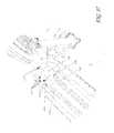
- FIGS. 12-15generally relate to an embodiment of a scooter frame comprising a deck, a neck, and a head tube, wherein the neck comprises two or more tubular members connecting the deck to the head tube.
- the frameis suitable for use with any scooter described herein.
- FIGS. 12-15show a rear side perspective view of an embodiment of a scooter frame assembly 300 that generally comprises a deck frame section 310 and a neck section 320 .
- the deck frame section 310can comprise a first tubular deck member 312 and a second tubular deck member 314 .
- the neck section 320can comprise a first tubular neck member 321 , a second tubular neck member 322 , a third tubular neck member 323 , a head tube 324 , and a base section 326 .
- the first tubular neck member 321can securely attach the second tubular deck member 314 and base section 326 with the head tube 324 .
- the second tubular neck member 322can securely attach the base section 326 with the head tube 324 .
- the third tubular neck member 323can securely attach the first tubular deck member 312 and the base section 326 with the head tube 324 .
- the first tubular deck member 312 , the second tubular deck member 314 , the first tubular neck member 321 , the second tubular neck member 322 , and the third tubular neck member 323each comprise a tubular member having an approximately circular cross section.
- the first tubular deck member 312 , the second tubular deck member 314 , the first tubular neck member 321 , the second tubular neck member 322 , and the third tubular neck member 323can comprise any other cross sectional shapes, including square, triangular, rectangular, and oval.
- the plurality of tubular neck members connecting the deck frame section with the head tubeenhances the strength of the connection.
- connection comprising a plurality of tubular neck memberscan provide ergonomic and riding style options not present in a connection comprising a single member.
- connection comprising a plurality of tubular memberscan facilitate the attachment of additional accessories, for the riding deck surface, or other attachments.
- the scooter frame assembly 300comprises three tubular neck members 321 , 322 , and 323 .
- the scooter frame assemblycan comprise two tubular neck members connecting the deck frame section 310 and head tube 324 .
- the scooter frame assemblycan comprise four or more tubular neck members connecting the deck frame section 310 and the head tube 324 .
- FIGS. 16-21illustrate the scooter neck sub-assembly comprising the neck and the head tube separate from the frame assembly of FIGS. 12-15 .
- the neckcomprises two or more tubular members connecting to the head tube.
- FIGS. 16-21show various views of the scooter neck section 320 that generally comprises the first tubular neck member 321 , the second tubular neck member 322 , the third tubular neck member 323 , the head tube 324 , a first base section 326 , and a second base section 328 .
- the first tubular neck member 321 and third tubular neck member 323can securely attach the first base section 326 with the head tube 324 .
- the second tubular neck member 322can securely attach the second base section 328 with the head tube 324 .
- the first base section 326is positioned above the deck frame section 310 and the second base section 328 is positioned below the deck frame section 310 .
- a forward portion of the first base section 326can include a cut-out to accommodate the second neck member 322 , as shown in FIG. 16 , for example.
- the base sections 326 , 328can be coupled to the deck frame section 310 by any suitable arrangement, such as by welding, for example.
- the base sections 326 , 328can be coupled to the deck frame section 310 along the entire forward surface, which is generally U-shaped in the illustrated arrangement.
- the base sections 326 , 328 spaced vertically as illustrated and preferably sandwiching the deck frame section 310 (e.g., forward portion 316 ) therebetweenadvantageously provide a strong and rigid arrangement for supporting the head tube 324 relative to the deck frame section 310 .
- FIGS. 22 and 23illustrate a modification of the scooter neck section 320 that generally comprises a first tubular neck member 321 , a second tubular neck member 322 , a third tubular neck member 323 , a head tube 324 , and a base section 326 .
- each neck member 321 , 322 , 323extends between the head tube 324 and the base section 326 and, preferably, connects to each of the head tube 324 and the base section 326 .
- the base section 326can be a frame tube arrangement of the frame assembly 300 , such as the deck frame section 310 (e.g., frame tubes 312 and 314 and/or a front frame tube portion 316 that couples forward ends of the frame tubes 312 , 314 ).
- the two separate base sectionsare omitted and the multiple neck members 321 , 322 , 323 preferably are coupled directly to the deck frame section 310 .
- the base or lower ends of the multiple neck members 321 , 322 , 323are spaced from one another in a lateral direction of the frame assembly 300 or scooter 200 .
- the neck member 321is coupled to one frame tube 314 and the neck member 323 is coupled to the other frame tube 312 .
- Such a lateral spacingadvantageously provides increased rigidity and reduces flex between the head tube 324 and the deck frame section 310 .
- the neck member 322can be substantially centrally located in a lateral direction of the frame assembly 300 .
- the neck members 321 , 322 , 323can be coupled to the head tube 324 at different heights or different axial locations.
- the side neck members 321 , 323can be coupled at one axial location and the central neck member 322 can be coupled at a different axial location on the head tube 324 .
- the side neck members 321 , 323can be coupled at a higher location or axial location closer to the upper end of the head tube 324 relative to the central neck member 322 .
- this arrangementcan be reversed, each neck member can be coupled at a different axial position or all of the neck members can be coupled at substantially the same axial location.
- An on-off switch 360is also illustrated that can connect to the wiring arrangement of the scooter 200 and can be used to turn the electric scooter on and off.
- FIGS. 24-28generally relate to alternative embodiments of a scooter neck assembly comprising a neck and a head tube, wherein the neck comprises a generally centered arrangement in the lateral direction of the associated scooter 200 .
- FIG. 24illustrates a neck assembly having a singular neck member 421 , which has a greater vertical dimension than its width or lateral dimension.
- FIGS. 25-28illustrate an embodiment that comprises at least two tubular members connecting to the head tube 424 in a substantially centralized configuration or stacked in a vertical direction.
- FIG. 24shows a top side perspective view of a scooter neck section 420 that generally comprises a first or upper neck portion 421 , a second or intermediate neck portion 422 , a third or lower neck portion 423 , a head tube 424 , and a base section 426 .
- the first neck portion 421is generally rounded or semi-cylindrical (semi-circular in cross-section) in shape.
- the second neck portion 422generally comprises side wall portions that connect ends of the first neck portion 421 to ends of the third neck portion 423 , which is shaped similar to the first neck portion 421 .
- the third neck portion 423is generally rounded or semi-cylindrical (semi-circular in cross-section) in shape.
- the neck section 420 of FIG. 24can securely attach the base section 426 with the head tube 424 and, due to the increased vertical dimension relative to a circular tube, can provide increased resistance to torsional flex between the deck section or base section 426 and the head tube 424 .
- FIG. 25shows a left side perspective view of an embodiment of a scooter neck section 420 that generally comprises a first tubular neck member 421 , a space 422 , a third tubular neck member 423 , a head tube 424 , and a base section 426 .
- the first tubular neck member 421 and third tubular neck member 423are separated by the space 422 and can be configured to be aligned along a midsection of the base section 426 .
- the ends of the neck members 421 , 423 connected to the head tube 424are closer than the ends of the neck members 421 , 423 connected to the base section 426 . That is, the space 422 is smaller near the head tube 424 and is larger near the base section 426 .
- this arrangementcould be reversed or the neck members 421 , 423 could be substantially parallel to one another.
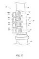
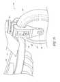
- FIGS. 29-32generally relate to embodiments related to scooters comprising a deck, head tube, steer tube, and clamp assembly, wherein the clamp assembly comprises three or more bolt clamp portions.
- the additional bolt clamp portionsadvantageously provide increased clamp force and/or an increased clamp force area.
- FIGS. 29 and 30show an embodiment of a portion of a scooter assembly 500 that comprises a neck 520 , a head tube 524 , a clamp assembly 530 , and a steering tube 540 .
- the clamp assembly 530is coupled to the steering tube 540 at or near a bottom portion of the steering tube 540 above the head tube 524 and secures the fork 528 ( FIG. 31 ) relative to the head tube 524 .
- FIGS. 31 and 32show a side view of the scooter assembly 500 with clamp bolts in place in the clamp assembly 530 .
- the clamp assembly 530comprises a first bolt section 532 , a second bolt section 534 , a third bolt section 536 , and a fourth bolt section 538 .
- the first bolt section 532can comprise a first ear 532 A, a second ear 532 B, and an opening 532 C configured to receive a bolt.
- the second bolt section 534can comprise a first ear 534 A, a second ear 534 B, and an opening 534 C configured to receive a bolt.
- the third bolt section 536can comprise a first ear 536 A, a second ear 536 B, and an opening 536 C configured to receive a bolt.
- the fourth bolt section 538can comprise a first ear 538 A, a second ear 538 B, and an opening 538 C configured to receive a bolt.
- the bolt sectionsare vertically (or axially) stacked and can be equidistant from one another.
- the clamp assemblycomprises three or less bolt sections. In other alternative embodiments, the clamp assembly can comprise five or more bolt sections.
- boltcan include bolts, screws, or any other suitable fastening member unless otherwise indicated either explicitly or by the context of the disclosure.
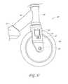
- FIGS. 33-35generally relate to embodiments related to scooters comprising a deck, front wheel, a neck, a head tube, a steer tube, a front fork connecting the front wheel to the steer tube, and a front fork cover, wherein the front fork cover generally surrounds the front fork as a protective exterior.
- the illustrated scooter assembly 600comprises a deck section 610 , a neck 620 , a head tube 624 , a front wheel 630 , and a front fork cover 640 .
- the front forkcan provide a means by which the front wheel 630 is mounted to a steering tube.
- the front forkcomprises a formed (e.g., bent) metal (e.g., steel) member, as shown, for example, in FIGS. 1 , 4 , 7 and 23 .
- the front fork of FIGS. 33-35preferably also comprises the same or a similar formed metal front fork member (partially visible through opening 644 ) that is partially or substantially completely enclosed by the fork cover 640 .
- the front wheel 630can be configured to rotate about a front-wheel axle 632 .
- the cover 640can be provided to cover some, a substantial portion or essentially all exterior surfaces (i.e., surfaces other than those facing the front wheel 630 ) of the front fork.
- the cover 640can serve as a protective exterior to the front fork.
- the cover 640can comprise a plastic, such as a hard plastic.
- the cover 640can comprise metal.
- the cover 640can be secured to the front fork by a fastening member 642 , such as a bolt, screw or other threaded (e.g., removable) fastener.
- Other fastening members/arrangementse.g., permanent or semi-permanent could also or alternatively be used, such as rivets for example.
- the fork cover 640can comprise a pair of cover portions on each side of the front wheel 630 . Front and/or rear portions of the fork cover 640 can extend towards the sides of the front wheel 630 and be shaped similarly to the front wheel 630 . Thus, the fork cover 640 , or cooperating cover portions, can define a cut-out or space that accommodates, but preferably closely follows, the shape of the front wheel 630 in either or both of the front and rear portions of the front fork. Such an arrangement inhibits the entry of foreign objects (e.g., small stones or pebbles) from entering into a space between the front fork and the front wheel 630 .
- foreign objectse.g., small stones or pebbles
- the provision of the fork cover 640allows the underlying (e.g., structural) portion of the front fork to be a relatively simple shape, which can be suitable for forming from a bent metal work piece and, thus, be relatively inexpensive to manufacture.
- the fork cover 640can be formed from, for example, a plastic material that can be made via, for example, a molding process (e.g., injection-molding) or other suitable process that permits inexpensive manufacture of more intricate shapes.
- a molding processe.g., injection-molding
- the combination of the front fork and fork cover 640provides suitable structural properties and also allows the fork assembly to closely follow the shape of the front wheel 630 in a relatively inexpensive arrangement.
- the cover 640can comprise an opening 644 that allows a portion of the underlying fork structure or another underlying structure.
- the opening 644can be provided for ornamental reasons or the underlying fork structure can include a protrusion that mates with the opening 644 to provide coupling of the fork cover 640 to the underlying fork structure in addition or in alternative to the fastening member 642 .
- FIGS. 36 and 37generally relate to an embodiment of a scooter 700 comprising a deck, front and rear wheels, a neck, a head tube, a steer tube, and a bash guard, wherein the bash guard 720 is provided underneath the deck and can serve a protective function and/or occupy a space between the front wheel and a forward surface of a lower frame portion to facilitate the scooter sliding over obstacles that could otherwise enter into the space between the front wheel and a forward surface of a lower frame portion.
- FIG. 37shows a perspective view of the bottom of the scooter assembly 700 including the bash guard 720 .
- the scooter assembly 700can be of any suitable arrangement, such as shown in FIG. 1 or otherwise shown or described herein.
- the scooter assembly 700can generally comprise a deck 210 , a neck 220 , a head tube 224 , a clamp assembly 250 , a steering tube 260 , a front wheel 230 , and a rear wheel 234 .
- the scooter assemblycan be an electric scooter.
- an electric motor 714 as shown in FIG. 37can be provided underneath approximately a rear portion 214 of the scooter assembly.
- a bash guard 720can be provided.
- the bash guard 720is provided at a location in front of the rear wheel.
- the bash guard 720can comprise a metal.
- the bash guard 720can comprise a hard plastic.
- the bash guard 720can be an angled piece having a bottom portion and a front portion, each of which can be substantially planar in some configurations.
- the bash guard 720can be a curved shape, preferably still having bottom and front portions.
- the bash guard 720can have any suitable width, such as substantially the same width as the scooter frame. In the illustrated arrangement, the bash guard 720 is somewhat narrower than the width of the scooter frame or at least the deck section of the scooter frame.
- the bash guard 720can comprise a plurality of openings 722 .
- the openings 722advantageously serve many functions.
- the openings 722allow for weight reduction of the bash guard 720 .
- the openings 722provide for metal forming options to present the bash guard in a solid sheet.
- the openings 722allow airflow to a battery box, and provide a draining mechanism so that the scooter assembly does not retain water in wet conditions.
- the underside of the scooter assemblycan comprise a first rail 710 and a second rail 712 .
- the bash guard 720can be fixedly attached to the first rail 710 and the second rail 712 via fastening members 724 and/or can be fixedly attached to the scooter frame (e.g., the base section 426 ) at or near a front portion of the bash guard 720 via a fastening member 724 .
- Other suitable arrangementscan also be used to secure the bash guard 720 to the scooter frame or other portion of the scooter 700 .
- FIG. 38generally relates to embodiments related to scooters comprising a deck, a first section on the deck comprising a first material, such as plastic, and a second section on the deck comprising a second material, such as metal (e.g., steel or aluminum).
- the first section and the second sectioncan comprise the same or different materials, but can be configured to provide different frictional and/or ornamental features.
- one sectioncan have a relatively smooth deck surface and the other section can have a non-smooth deck surface, which can include grip features, rough surface portions or openings (which can be void or occupied by another member), for example.
- FIG. 38shows a perspective view of an embodiment of a deck assembly 800 for a scooter assembly.
- the deck assembly 800can comprise a first deck portion 810 and a second deck portion 820 .
- the first deck portion 810comprises a type of plastic and the second deck portion 820 comprises metal.
- the first deck portion 810can comprise any plastic, metal, or other suitable material
- the second deck portion 820can comprise any plastic, metal, or other suitable material, which can be the same as or different from the material of the first deck portion.
- the first deck portion 810can comprise a rear first deck portion 812 and a front first deck portion 814
- the second deck portion 820can comprise a rear second deck portion 822 and a front second deck portion 824 .
- the first deck portion 810can be arranged such that the rear first deck portion 812 is uncovered by the second deck portion 820 , but the front first deck portion 814 is at least partially covered by the rear second deck portion 822 of the second deck portion 820 .
- lateral side portions of the first deck portion 814are uncovered and extend along opposite sides of the second deck portion 820 (e.g., the rear second deck portion 822 ).
- the front second deck portion 824 of the second deck portion 820can extend up a neck portion 830 of the scooter assembly.
- the first deck portion 810 and/or the second deck portion 820can be securely fixed to the deck assembly 800 via fastening members 828 or other suitable fastening arrangements.
- the second deck portion 820can comprise a plurality of openings 826 .
- an insertcomprising a gripping material, such as rubber or a rubber-like material, can be provided between the second deck portion 820 and the first deck portion 810 .
- portions of a rubber insertcan be configured to protrude through the openings 826 of the second deck portion 820 .
- Such portions of the rubber insertcan be substantially even with the deck surface of the second deck portion 820 surrounding the openings 826 or can protrude so as to be raised above the deck surface of the second deck portion 820 surrounding the openings 826 .
- the second deck portion 820can provide a surface that can deliver improved gripping ability to a rider of the scooter assembly.
- a ridercan recognize a difference in surface texture between the first deck portion 810 and the second deck portion 820 , preferably by feel and without looking at the deck surface.
- FIG. 39generally relates to embodiments related to scooters comprising a deck, a first section on the deck comprising a material (e.g., plastic) configured to provide a first level of traction or frictional characteristics, and a second section on the deck comprising the same material (e.g., plastic) and configured to provide a second level of traction or frictional characteristics (e.g., coefficient of friction).
- a materiale.g., plastic
- a second section on the deckcomprising the same material (e.g., plastic) and configured to provide a second level of traction or frictional characteristics (e.g., coefficient of friction).
- FIG. 39shows a top view of an embodiment of a deck assembly 900 for a scooter assembly.
- the deck assembly 900can comprise a first deck portion 910 and a second deck portion 920 .
- the first deck portion 910comprises a type of plastic having a first surface texture
- the second deck portion 920comprises a type of plastic having a second surface texture.
- the first deck portion 910can comprise any plastic, metal, or other suitable material having a first surface texture
- the second deck portion 920can comprise any plastic, metal, or other suitable material having a second surface texture.
- the first surface texture and second surface textureare different such that the deck assembly 900 is provided with different modular grip surfaces.
- the different modular grip surfacescan assist a scooter rider in locating various positions of the deck assembly 900 by feeling the texture of the deck assembly surface with the scooter rider's feet.
- different materialscan be used for the different portions 910 , 920 .
- the relative location of the first deck portion 910 and the second deck portion 920can vary.
- the first deck portion 910comprises a rear first deck portion 912 and a front first deck portion 914 .
- the second deck portion 920can be situated in proximity to the rear first deck portion 912 .
- the second deck portioncan be situated in proximity to any other part of the first deck portion 910 , including the front first deck portion 914 and a center part of the first deck portion 910 .
- the deck assemblycan comprise three or more deck portions, each of which can have the same or different surface texture of any of the other deck portions, thereby assisting a scooter rider in locating any section of the deck assembly by feeling the texture of the deck assembly with the scooter rider's feet.
- the second deck portion 920can function as a foot brake.
- the scooter assemblycomprises a foot brake formed as a part of a rear portion of the deck assembly.
- a rear portion of the deck assemblycan be configured to pivot about an axis to provide a braking pressure to a rear wheel.
- a scooter ridercan be assisted in easily locating the foot brake.
- a second deck portion 920 with a differently textured surfacecan also assist a scooter rider in differentiating between the foot brake and the rest of the deck assembly in order to avoid inadvertent pressing of the foot brake.
Landscapes
- Engineering & Computer Science (AREA)
- Mechanical Engineering (AREA)
- Chemical & Material Sciences (AREA)
- Combustion & Propulsion (AREA)
- Transportation (AREA)
- Automatic Cycles, And Cycles In General (AREA)
- Electric Propulsion And Braking For Vehicles (AREA)
Abstract
Description
Claims (25)
Priority Applications (5)
| Application Number | Priority Date | Filing Date | Title |
|---|---|---|---|
| US14/043,625US9045189B2 (en) | 2012-10-02 | 2013-10-01 | Scooter assemblies |
| US14/723,892US9994278B2 (en) | 2012-10-02 | 2015-05-28 | Scooter assemblies |
| US16/002,937US20190135367A1 (en) | 2012-10-02 | 2018-06-07 | Scooter assemblies |
| US16/794,836US20210009227A1 (en) | 2012-10-02 | 2020-02-19 | Scooter assemblies |
| US17/833,801US20230127757A1 (en) | 2012-10-02 | 2022-06-06 | Scooter assemblies |
Applications Claiming Priority (2)
| Application Number | Priority Date | Filing Date | Title |
|---|---|---|---|
| US201261708996P | 2012-10-02 | 2012-10-02 | |
| US14/043,625US9045189B2 (en) | 2012-10-02 | 2013-10-01 | Scooter assemblies |
Related Child Applications (1)
| Application Number | Title | Priority Date | Filing Date |
|---|---|---|---|
| US14/723,892ContinuationUS9994278B2 (en) | 2012-10-02 | 2015-05-28 | Scooter assemblies |
Publications (2)
| Publication Number | Publication Date |
|---|---|
| US20140091546A1 US20140091546A1 (en) | 2014-04-03 |
| US9045189B2true US9045189B2 (en) | 2015-06-02 |
Family
ID=50384164
Family Applications (10)
| Application Number | Title | Priority Date | Filing Date |
|---|---|---|---|
| US14/043,625Expired - Fee RelatedUS9045189B2 (en) | 2012-10-02 | 2013-10-01 | Scooter assemblies |
| US14/043,748ActiveUS9168965B2 (en) | 2012-10-02 | 2013-10-01 | Electric scooter assemblies |
| US14/723,892ActiveUS9994278B2 (en) | 2012-10-02 | 2015-05-28 | Scooter assemblies |
| US14/920,835ActiveUS10124851B2 (en) | 2012-10-02 | 2015-10-22 | Electric scooter assemblies |
| US16/002,937AbandonedUS20190135367A1 (en) | 2012-10-02 | 2018-06-07 | Scooter assemblies |
| US16/186,256Expired - Fee RelatedUS11001329B2 (en) | 2012-10-02 | 2018-11-09 | Electric scooter assemblies |
| US16/794,836AbandonedUS20210009227A1 (en) | 2012-10-02 | 2020-02-19 | Scooter assemblies |
| US17/316,514AbandonedUS20210403116A1 (en) | 2012-10-02 | 2021-05-10 | Electric scooter assemblies |
| US17/833,801AbandonedUS20230127757A1 (en) | 2012-10-02 | 2022-06-06 | Scooter assemblies |
| US18/599,050AbandonedUS20240294226A1 (en) | 2012-10-02 | 2024-03-07 | Electric scooter assemblies |
Family Applications After (9)
| Application Number | Title | Priority Date | Filing Date |
|---|---|---|---|
| US14/043,748ActiveUS9168965B2 (en) | 2012-10-02 | 2013-10-01 | Electric scooter assemblies |
| US14/723,892ActiveUS9994278B2 (en) | 2012-10-02 | 2015-05-28 | Scooter assemblies |
| US14/920,835ActiveUS10124851B2 (en) | 2012-10-02 | 2015-10-22 | Electric scooter assemblies |
| US16/002,937AbandonedUS20190135367A1 (en) | 2012-10-02 | 2018-06-07 | Scooter assemblies |
| US16/186,256Expired - Fee RelatedUS11001329B2 (en) | 2012-10-02 | 2018-11-09 | Electric scooter assemblies |
| US16/794,836AbandonedUS20210009227A1 (en) | 2012-10-02 | 2020-02-19 | Scooter assemblies |
| US17/316,514AbandonedUS20210403116A1 (en) | 2012-10-02 | 2021-05-10 | Electric scooter assemblies |
| US17/833,801AbandonedUS20230127757A1 (en) | 2012-10-02 | 2022-06-06 | Scooter assemblies |
| US18/599,050AbandonedUS20240294226A1 (en) | 2012-10-02 | 2024-03-07 | Electric scooter assemblies |
Country Status (3)
| Country | Link |
|---|---|
| US (10) | US9045189B2 (en) |
| CN (1) | CN104684799B (en) |
| WO (1) | WO2014055566A1 (en) |
Cited By (22)
| Publication number | Priority date | Publication date | Assignee | Title |
|---|---|---|---|---|
| US20170001683A1 (en)* | 2015-07-01 | 2017-01-05 | GM Global Technology Operations LLC | Kickscooter with detachable electric drive module with hub-center steering and vibration dampening wheel |
| USD779594S1 (en) | 2013-05-17 | 2017-02-21 | Bravo Sports | Scooter connector tubing |
| US9592876B2 (en) | 2013-12-18 | 2017-03-14 | Bravo Sports | Three-wheeled electric scooter |
| USD810836S1 (en) | 2015-10-29 | 2018-02-20 | Razor Usa Llc | Electric scooter |
| USD811489S1 (en)* | 2012-03-15 | 2018-02-27 | Razor Usa Llc | Electric scooter |
| USD818541S1 (en) | 2016-09-08 | 2018-05-22 | Razor Usa Llc | Electric scooter |
| US9994278B2 (en) | 2012-10-02 | 2018-06-12 | Bravo Sports | Scooter assemblies |
| US10099745B2 (en) | 2012-01-20 | 2018-10-16 | Razor Usa Llc | Braking device for a personal mobility vehicle |
| US10189533B2 (en) | 2013-12-18 | 2019-01-29 | Bravo Sports | Electric scooter |
| USD941929S1 (en) | 2016-01-22 | 2022-01-25 | Razor Usa Llc | Electric scooter |
| US11697469B2 (en) | 2018-06-01 | 2023-07-11 | Razor Usa Llc | Personal mobility vehicles with detachable drive assembly |
| US11702048B2 (en) | 2020-11-25 | 2023-07-18 | Alexander Kandemir | Braking apparatus for a children's kick scooter |
| USD1020912S1 (en) | 2018-06-05 | 2024-04-02 | Razor Usa Llc | Electric scooter |
| US11975794B2 (en) | 2016-01-22 | 2024-05-07 | Razor Usa Llc | Freewheeling electric scooter |
| USD1029949S1 (en) | 2017-01-18 | 2024-06-04 | Razor Usa Llc | Electric scooter |
| US12011654B2 (en) | 2016-07-15 | 2024-06-18 | Razor Usa Llc | Powered mobility systems |
| US12059971B2 (en) | 2020-08-07 | 2024-08-13 | Razor Usa Llc | Electric scooter with removable battery |
| USD1050269S1 (en) | 2020-09-14 | 2024-11-05 | Razor Usa Llc | Scooter |
| USD1053956S1 (en) | 2020-09-14 | 2024-12-10 | Razor Usa Llc | Scooter |
| US12257492B2 (en) | 2008-03-06 | 2025-03-25 | Leverage Design Ltd. | Transportation device with pivoting axle |
| USD1072062S1 (en) | 2020-09-14 | 2025-04-22 | Razor Usa Llc | Electric scooter |
| US12403974B2 (en) | 2016-01-22 | 2025-09-02 | Razor Usa Llc | Electric scooter |
Families Citing this family (22)
| Publication number | Priority date | Publication date | Assignee | Title |
|---|---|---|---|---|
| TWM455636U (en)* | 2013-01-18 | 2013-06-21 | Laing Ban Internat Inc | Rear shock absorbing structure of skateboard |
| CN104210592B (en)* | 2014-06-19 | 2016-08-31 | 浙江群英车业有限公司 | A kind of Segway Human Transporter |
| US10399632B2 (en)* | 2014-12-18 | 2019-09-03 | The Glorious Empire, Llc | Adjustable rear wheel hood brake/stop system for free style kick scooters |
| US9643679B2 (en) | 2015-02-11 | 2017-05-09 | Razor Usa Llc | Scooter with rotational connection |
| CN105730577B (en)* | 2016-02-03 | 2018-09-25 | 朱慧敏 | A kind of two-in-one dual-purpose new baby carriage |
| US10144480B2 (en)* | 2017-01-22 | 2018-12-04 | Changsha Mantour Technology Co., Ltd. | Electric scooter |
| DE102017107035A1 (en)* | 2017-03-31 | 2018-10-04 | Helmut Abel | scooter |
| USD855116S1 (en)* | 2017-09-12 | 2019-07-30 | Razor Usa Llc | Personal mobility vehicle |
| TWM560129U (en)* | 2017-12-28 | 2018-05-11 | Apo International Co Ltd | Battery with quick charging function |
| EP3735373A1 (en)* | 2018-01-05 | 2020-11-11 | Birota | Scooter suitable for compact storage |
| DE102018206225B4 (en)* | 2018-04-23 | 2021-11-18 | Audi Ag | Scooter and method of operating a scooter |
| US11383787B2 (en) | 2018-09-26 | 2022-07-12 | GM Global Technology Operations LLC | Multi-axis pivoting coupler joints and drivetrain architectures for intelligent electric scooters |
| US11001152B2 (en) | 2018-09-26 | 2021-05-11 | GM Global Technology Operations LLC | Powertrain architectures and control algorithms for intelligent electric scooters |
| US10419904B2 (en)* | 2018-10-24 | 2019-09-17 | Neuron Corporation | Mobile connectivity and self-generating illumination electric scooter |
| CN110155230A (en)* | 2019-02-02 | 2019-08-23 | 杭州骑客智能科技有限公司 | Human-computer interaction body-sensing vehicle and its support frame |
| EP3934970A4 (en)* | 2019-03-08 | 2022-12-14 | Neutron Holdings, Inc. | An electric-powered personal transport vehicle |
| US11038235B2 (en) | 2019-06-27 | 2021-06-15 | Avant Enterprises, Inc. | Electric scooter with battery pack interchangeable with power and gardening tool |
| US11912358B2 (en)* | 2019-10-08 | 2024-02-27 | Vidyadhar Gurram | Modular vehicle with detachable modules that exchange information and power wirelessly |
| US11597285B2 (en) | 2020-03-06 | 2023-03-07 | Toyota Jidosha Kabushiki Kaisha | Systems, devices, and methods for sharing personal mobility devices |
| US11850969B1 (en) | 2022-08-23 | 2023-12-26 | Intercontinental Mobility Company | Portable motorized vehicles |
| USD1091384S1 (en)* | 2023-08-22 | 2025-09-02 | Zhejiang Sanyou Vehicle Technology Co., Ltd. | Electric scooter |
| EP4541703A1 (en)* | 2023-10-16 | 2025-04-23 | Flash Motors Ltd | Electric scooter |
Citations (10)
| Publication number | Priority date | Publication date | Assignee | Title |
|---|---|---|---|---|
| US6382366B1 (en)* | 2001-01-29 | 2002-05-07 | Yung-Tsun Chang | Brake device in a skateboard cart |
| US20020117825A1 (en)* | 2001-02-26 | 2002-08-29 | Nina Ho | Scooter having a rear wheel hood mounted on a rear wheel thereof |
| US20060266570A1 (en) | 2003-08-04 | 2006-11-30 | Go Motorboards, Llc | Motorized scooter |
| US20080203691A1 (en)* | 2007-02-26 | 2008-08-28 | Jung-Yu Hsu | Scooter Having An Anti-Skid Brake Device |
| USD581991S1 (en) | 2007-12-21 | 2008-12-02 | Bravo Sports | Scooter |
| US20090200768A1 (en) | 2008-02-08 | 2009-08-13 | Bravo Sports | Non-motorized vehicle |
| US20110031711A1 (en) | 2008-01-30 | 2011-02-10 | H Grossman Ltd | Scooter |
| CN102050182A (en) | 2009-11-05 | 2011-05-11 | 刘岗 | Micro foldable and contractible electric vehicle |
| US8613458B2 (en)* | 2010-02-02 | 2013-12-24 | Richard Ghisolfi | Extensible two-wheeled vehicle |
| US8662508B2 (en)* | 2004-05-05 | 2014-03-04 | H Grossman Limited | Scooter |
Family Cites Families (179)
| Publication number | Priority date | Publication date | Assignee | Title |
|---|---|---|---|---|
| US2241686A (en) | 1938-07-11 | 1941-05-13 | Chicago Roller Skate Co | Wheel guard |
| US3570620A (en)* | 1969-01-15 | 1971-03-16 | Allan R Thieme | Electrically powered vehicle |
| US4124222A (en) | 1977-09-19 | 1978-11-07 | Diker-Moe Associates | Treadle scooter |
| US4168076A (en)* | 1978-06-14 | 1979-09-18 | Johnson Noel K | Skateboard with tail brake |
| US4315569A (en) | 1980-07-14 | 1982-02-16 | Champion International Corporation | Replacement wheel display carton |
| JPS5820581A (en) | 1981-07-24 | 1983-02-07 | 本田技研工業株式会社 | Vehicle frame structure |
| FR2555908B1 (en) | 1983-12-01 | 1986-10-24 | Vallot Rene | DEVICE FOR ADAPTING WHEELS OF A DIAMETER AND A WIDER WIDTH ON "ROLLER-SKATE" WHEELS OR WHEELS |
| USD291211S (en) | 1984-11-21 | 1987-08-04 | Man Na C | Scooter |
| US4875142A (en) | 1986-04-01 | 1989-10-17 | Donald Spector | Bicycle safety lights |
| USD292221S (en) | 1986-12-19 | 1987-10-06 | Schwinn Bicycle Company | Scooter |
| USD295428S (en)* | 1987-04-13 | 1988-04-26 | Cummings Darold B | Scooter |
| USD312485S (en)* | 1987-04-16 | 1990-11-27 | Gt Bicycles, Inc. | Scooter frame |
| US4761014A (en) | 1987-04-28 | 1988-08-02 | Huang Kung Hsiung | Propulsion of scooters |
| US4799701A (en) | 1987-07-06 | 1989-01-24 | Lindau Mark S | Scooter |
| USD300756S (en) | 1987-11-19 | 1989-04-18 | Cummings Darold B | Scooter |
| US4799702A (en) | 1988-05-11 | 1989-01-24 | Tarrassa Wang | Scooter with turnable rear wheel |
| US5039121A (en) | 1989-10-11 | 1991-08-13 | Rick L. Hardin | Tri-skater |
| US5054848A (en) | 1990-08-29 | 1991-10-08 | Liu Chung Hsin | Folding chair frame tube positioning device |
| US5214944A (en) | 1992-03-31 | 1993-06-01 | Wolthoff Charles E | Rod stabilizer and clamping device |
| EP0570653A1 (en) | 1992-05-18 | 1993-11-24 | Roberto Piazzi | Motor vehicle for golf foreseen its size reduction |
| US5376869A (en) | 1993-02-11 | 1994-12-27 | General Electric Company | Electric vehicle drive train with rollback detection and compensation |
| DE4309170A1 (en) | 1993-03-22 | 1994-09-29 | Nikipack Verpackungs Und Monta | Packaging element for objects |
| US5333477A (en) | 1993-07-20 | 1994-08-02 | Phillip Davis | Vehicle parking boot |
| WO1997015485A1 (en)* | 1995-10-26 | 1997-05-01 | Fruechtenicht Robert D | Surfing scooter |
| US6739606B2 (en) | 1996-01-29 | 2004-05-25 | Marky Sparky, Inc. | Dual-footboard scooter |
| US5775452A (en) | 1996-01-31 | 1998-07-07 | Patmont Motor Werks | Electric scooter |
| US5899474A (en) | 1996-07-12 | 1999-05-04 | Grutzik; Joe | Frequency-accelerated velocipede |
| CN2286691Y (en) | 1996-11-12 | 1998-07-29 | 金华市金信科技风险投资管理有限公司 | Control device of electric booster |
| USD392001S (en) | 1996-12-23 | 1998-03-10 | Far Great Plastics Industrial Co., Ltd. | Frame of scooter |
| US5950498A (en)* | 1997-08-07 | 1999-09-14 | Gossett; J. Cary | Handle storage apparatus and method |
| USD433718S (en) | 1998-12-18 | 2000-11-14 | ZapWorld.com | Portable collapsible scooter |
| TW399589U (en) | 1999-02-02 | 2000-07-21 | J D Components Co Ltd | Rear wheel brake device of sliding scooter |
| CN2376398Y (en) | 1999-04-19 | 2000-05-03 | 武汉云鹤车辆制造厂 | Electric vehicle controller |
| US6250656B1 (en) | 1999-06-01 | 2001-06-26 | Jorge L. Ibarra | Skateboard-bicycle combination |
| US6347681B1 (en) | 1999-08-27 | 2002-02-19 | Patmont Motor Werks | Electrically integrated scooter with dual suspension and stowage mechanism |
| JP2001095107A (en) | 1999-09-21 | 2001-04-06 | Yamaha Motor Co Ltd | Method for controlling power source of hybrid-driven mobile |
| AUPQ470399A0 (en)* | 1999-12-16 | 2000-01-20 | Reginato, Robert | Scooter assembly |
| JP3548477B2 (en) | 2000-01-25 | 2004-07-28 | 鈴木 康之 | Travel speed control device for electric light vehicle and electric light vehicle |
| CN2419148Y (en) | 2000-01-26 | 2001-02-14 | 威海天威企业集团有限责任公司 | Foldable electric spokeless pedal vehicle |
| US20040050603A1 (en)* | 2000-02-23 | 2004-03-18 | Jaeger Eduard A. | Mounting arrangement for vehicle power source |
| USD433654S (en) | 2000-02-24 | 2000-11-14 | George Gorvine | Motorized skate board with seat and footrests |
| TW427285U (en) | 2000-02-25 | 2001-03-21 | Juang Jin Cheng | Improved folding structure for scooter |
| TW461413U (en) | 2000-04-27 | 2001-10-21 | Chen Shin Ping | Improved structure for scooter |
| US6299186B1 (en) | 2000-04-28 | 2001-10-09 | Chuan-Fu Kao | Antishock structure of scooter |
| USD452886S1 (en) | 2000-05-24 | 2002-01-08 | Leao Wang | Kickboard |
| USD437363S1 (en) | 2000-06-29 | 2001-02-06 | Far Great Plastics Industrial Co., Ltd. | Scooter frame |
| TW505133U (en)* | 2000-07-03 | 2002-10-01 | J D Components Co Ltd | Power device for skate scooter |
| USD441323S1 (en) | 2000-07-27 | 2001-05-01 | Dar-Hsiang Cheng | Electric vehicle |
| TW481136U (en) | 2000-09-05 | 2002-03-21 | Sz-Yu Lin | Steering mechanism for skating scooter |
| US6273205B1 (en) | 2000-09-13 | 2001-08-14 | Shui-Te Tsai | Power clutch mechanism of scooter |
| US6315307B1 (en)* | 2000-09-21 | 2001-11-13 | Kai-Wen Chen | Collapsible scooter |
| US6298952B1 (en) | 2000-09-29 | 2001-10-09 | Shui-Te Tsai | Brake of rear wheel of scooter |
| USD447188S1 (en) | 2000-10-21 | 2001-08-28 | Mey-Chu Lan | Skating cart |
| TW481157U (en) | 2000-11-15 | 2002-03-21 | Sun Yu Le Co Ltd | Braking structure for skating scooter |
| USD454599S1 (en)* | 2000-12-18 | 2002-03-19 | Far Great Plastics Industrial Co., Ltd. | Scooter frame |
| USD457574S1 (en) | 2000-12-18 | 2002-05-21 | Far Great Plastics Industrial Co., Ltd. | Scooter frame |
| USD456460S1 (en) | 2000-12-21 | 2002-04-30 | Shih Fan Tseng | Electric scooter |
| CN2493513Y (en) | 2001-01-11 | 2002-05-29 | 张金六 | Hanging card type label of products |
| US6481728B2 (en) | 2001-02-02 | 2002-11-19 | Shou-Mao Chen | Braking structure for a scooter |
| USD456461S1 (en) | 2001-02-20 | 2002-04-30 | Jeff Koch | Motorized scooter |
| USD454377S1 (en) | 2001-02-22 | 2002-03-12 | Hao Yih Trading Co., Ltd. | Scooter |
| US6378642B1 (en)* | 2001-02-26 | 2002-04-30 | Eugene R Sutton | Motorized scooter |
| USD449860S1 (en) | 2001-02-26 | 2001-10-30 | Tony Lin | Electric scooter |
| USD450355S1 (en) | 2001-04-06 | 2001-11-13 | Porter Chan | Electric scooter |
| USD448429S1 (en) | 2001-04-20 | 2001-09-25 | High Spot Industrial Co., Ltd. | Scooter |
| US20020170763A1 (en) | 2001-05-16 | 2002-11-21 | Townsend Arthur R. | Electric scooter with selectable speed ranges |
| USD470438S1 (en) | 2001-09-03 | 2003-02-18 | Honda Giken Kogyo Kabushiki Kaisha | Motor scooter |
| USD469348S1 (en) | 2001-12-21 | 2003-01-28 | Cfllco Partnership | Accessory clamshell design |
| USD464002S1 (en) | 2001-12-31 | 2002-10-08 | Chien-Chang Ho | Scooter |
| US20030127822A1 (en) | 2002-01-08 | 2003-07-10 | Fleck Steven James | Transportation device |
| USD470409S1 (en) | 2002-02-15 | 2003-02-18 | Christine M. Clarke | Display packaging for products |
| US6752229B2 (en)* | 2002-07-23 | 2004-06-22 | Chien-Chang Ho | Vehicle with motor and engine |
| US20040026144A1 (en)* | 2002-08-07 | 2004-02-12 | May-Chu Lan | Electric driving scooter |
| USD492367S1 (en)* | 2002-10-23 | 2004-06-29 | The Electric Transportation Company, Llc | Electric scooter |
| US20040079571A1 (en)* | 2002-10-24 | 2004-04-29 | Erik Laver | Motorized scooter |
| KR100578411B1 (en) | 2002-11-27 | 2006-05-11 | 김영훈 | Automotive wheel locking device |
| USD489771S1 (en) | 2002-12-31 | 2004-05-11 | Erik Laver Success Systems | Motorized scooter |
| USD483078S1 (en) | 2003-02-10 | 2003-12-02 | Cobra King Technology Development Co., Ltd. | Motor scooter |
| US7441914B2 (en) | 2003-04-01 | 2008-10-28 | Lunasee, Llc | Phosphorescent charging system for wheeled vehicles having phosphorescent wheels |
| USD487908S1 (en) | 2003-06-06 | 2004-03-30 | Currie Technologies | Low rider scooter |
| USD486532S1 (en) | 2003-06-09 | 2004-02-10 | Sharper Image Corporation | Scooter |
| USD497397S1 (en) | 2003-08-18 | 2004-10-19 | Razor Usa Llc | Electric skate scooter |
| US6933847B2 (en) | 2003-10-29 | 2005-08-23 | A&H Manufacturing, Co. | Anti-theft tag |
| US7255191B2 (en)* | 2003-10-31 | 2007-08-14 | Vectrix Corporation | Composite construction vehicle frame |
| USD505457S1 (en) | 2003-12-12 | 2005-05-24 | Ka-Ming Wong | Scooter |
| US7100728B2 (en) | 2003-12-19 | 2006-09-05 | Shih-Feng Huang | Driving mechanism of an electrically-operated vehicle |
| USD516132S1 (en) | 2004-01-21 | 2006-02-28 | Razor Usa Llc | Scooter |
| US7281345B2 (en) | 2004-02-04 | 2007-10-16 | Bedford Industries, Inc. | Merchandise labeling |
| US7178813B1 (en)* | 2004-02-06 | 2007-02-20 | Jostro Products, Inc. | Scooter |
| KR100583430B1 (en) | 2004-03-08 | 2006-05-24 | 양경숙 | Wheel variable scooter |
| US20050230930A1 (en) | 2004-04-20 | 2005-10-20 | Charles Chung | Scooter |
| USD528168S1 (en) | 2004-05-07 | 2006-09-12 | The Bikeboard Company, Llc | Hybrid skateboard, scooter and bicycle frame |
| US7044488B1 (en) | 2004-09-30 | 2006-05-16 | Arone Hamend | Scooter assembly |
| US6997022B1 (en) | 2005-01-10 | 2006-02-14 | Demange Craig | Wheel lock for a trailer |
| USD533601S1 (en)* | 2005-02-14 | 2006-12-12 | Simonides Guzman Moreira | Scooter |
| US7267352B2 (en)* | 2005-02-18 | 2007-09-11 | Shimano, Inc. | Apparatus for mounting an electrical component to a bicycle |
| US7597333B2 (en)* | 2006-04-05 | 2009-10-06 | Acorn Products, Llc | Brake assembly and scooters and skateboards including the same |
| WO2007128124A1 (en)* | 2006-05-08 | 2007-11-15 | Lakehead University | Powered foldable scooter |
| DK176497B3 (en) | 2007-03-08 | 2018-06-18 | Protanium B V | Bicycle frame with built-in and removable battery |
| USD564037S1 (en) | 2007-03-26 | 2008-03-11 | Radio Flyer, Inc. | Scooter |
| NL1033702C2 (en) | 2007-04-17 | 2008-10-20 | Askove Bv | Immobilization device for a vehicle wheel and method for immobilizing a vehicle wheel. |
| CN201049715Y (en)* | 2007-05-11 | 2008-04-23 | 潘文超 | Folding scooter equipped with light and bell |
| US8500147B2 (en) | 2007-12-21 | 2013-08-06 | Radio Flyer Inc. | Folding scooter |
| DK2106993T3 (en) | 2008-04-03 | 2012-05-29 | C10 Ventures B V | Collapsible motor vehicle |
| ITFI20080089A1 (en) | 2008-05-05 | 2009-11-06 | Riccardo Ardovini | "A SYSTEM AND A PROCEDURE FOR FORCED LOCKING / UNLOCKING OF VEHICLES USING A COMBINATION DEVICE" |
| US20100013183A1 (en) | 2008-07-18 | 2010-01-21 | Rurong He | Three wheeled scooter |
| US8322735B2 (en) | 2008-09-05 | 2012-12-04 | Robert Steinbach | Freestyle scooter |
| TWM354567U (en)* | 2008-10-14 | 2009-04-11 | Yi-Shiuan Shiue | Hand grasping cover set with blinking luminescence for bicycle |
| US7937975B2 (en) | 2008-10-31 | 2011-05-10 | B&G Plastics, Inc. | Wheel boot |
| GB2466241A (en) | 2008-12-15 | 2010-06-23 | Hy Pro Internat Ltd | Foot propelled scooter with sound effects |
| US20100291418A1 (en)* | 2009-05-15 | 2010-11-18 | Sinoelectric Powertrain Corporation | Battery packs, systems, and methods |
| US8328218B2 (en) | 2009-07-13 | 2012-12-11 | Columbia Cycle Works, LLC | Commuter vehicle |
| US7819245B1 (en) | 2009-09-04 | 2010-10-26 | Division Six Sports, Inc. | Clam shell packaging for wheel device |
| US7886901B1 (en) | 2009-09-04 | 2011-02-15 | Division Six Sports, Inc. | Clam shell packaging device |
| JP2011079510A (en)* | 2009-09-10 | 2011-04-21 | Makita Corp | Electric vehicle |
| US9586471B2 (en) | 2013-04-26 | 2017-03-07 | Carla R. Gillett | Robotic omniwheel |
| US8657522B2 (en)* | 2010-02-12 | 2014-02-25 | Andrew David Broussard | Threadless fork compression system and method for kick style scooter |
| US8167074B1 (en)* | 2010-03-17 | 2012-05-01 | Joseph Tsiyoni | Three-wheel, driver's stand-up, portable, leverless vehicle, with foot brake lever and connecting method thereoff |
| FR2958259B1 (en)* | 2010-04-01 | 2014-04-11 | Matra Mfg & Services | TWO-WHEELS ELECTRIC |
| US9139244B2 (en)* | 2010-06-18 | 2015-09-22 | Sonic Grip Limited | Sound emitting handgrip for a tubular handlebar |
| USD648402S1 (en) | 2010-07-12 | 2011-11-08 | Shanghai Magic Wheels Sporting Goods Co., Ltd. | Scooter |
| US8091906B1 (en) | 2010-07-20 | 2012-01-10 | Wang-Chuan Chen | Scooter including brake system |
| TWM397919U (en) | 2010-09-01 | 2011-02-11 | Dijiya Energy Saving Technology Inc | Integrated wheel |
| US9079455B2 (en) | 2010-09-02 | 2015-07-14 | Jake Devries | Wheel cover |
| US8662228B2 (en) | 2011-01-19 | 2014-03-04 | Green Lite Motors Corporation | Free-to-lean three-wheeled passenger vehicle, power plant controller and body therefor |
| ES2669309T3 (en) | 2011-02-28 | 2018-05-24 | Honda Motor Co., Ltd. | Vehicle approach alert device for straddle type electric vehicle |
| US8613457B2 (en)* | 2011-03-11 | 2013-12-24 | Andreas C. Wegener | Scooter assemblies and scooter deck assemblies |
| USD654962S1 (en) | 2011-04-15 | 2012-02-28 | Zike, Llc | Frame |
| USD651659S1 (en) | 2011-04-15 | 2012-01-03 | Zike, Llc | Frame |
| USD654965S1 (en) | 2011-05-31 | 2012-02-28 | Radio Flyer Inc | Scooter |
| USD672400S1 (en) | 2011-07-13 | 2012-12-11 | Larry Pizzi | Three-wheeled electric scooter |
| US8870421B2 (en) | 2011-08-04 | 2014-10-28 | Andrew Michael WARD | Bicycle handlebar with integral lighting system |
| US9499042B2 (en) | 2011-09-30 | 2016-11-22 | Brp-Powertrain Gmbh & Co. Kg | Hybrid vehicle drivetrain |
| CN202987412U (en) | 2012-01-20 | 2013-06-12 | 雷泽美国有限责任公司 | Brake assembly for personal movable vehicle and personal movable vehicle |
| US8864152B1 (en) | 2012-02-12 | 2014-10-21 | Marcelo Danze | Deck assembly for wheeled vehicle |
| WO2013128437A1 (en) | 2012-02-13 | 2013-09-06 | Zaid Amir | Urban vehicle |
| USD693414S1 (en) | 2012-03-15 | 2013-11-12 | Razor Usa Llc | Electric scooter |
| US8979110B2 (en)* | 2012-03-16 | 2015-03-17 | Specialized Bicycle Components, Inc. | Bicycle with battery mount |
| US8820460B2 (en) | 2012-03-27 | 2014-09-02 | Razor Usa Llc | Powered personal mobility vehicle with rotating wheels |
| USD698868S1 (en) | 2012-08-08 | 2014-02-04 | Nicer Holdings Limited | Scooter |
| US8985602B2 (en) | 2012-08-08 | 2015-03-24 | Nicer Holdings Limited | Scooter |
| CN202863656U (en) | 2012-09-04 | 2013-04-10 | 周智慧 | Electric scooter |
| WO2014047468A1 (en) | 2012-09-21 | 2014-03-27 | Bravo Corporation | Wheel cover for wheeled vehicles |
| US9045189B2 (en) | 2012-10-02 | 2015-06-02 | Bravo Sports | Scooter assemblies |
| FR2998858B1 (en) | 2012-12-05 | 2014-11-21 | Michelin & Cie | ELECTRICAL ASSISTANCE DEVICE FOR BICYCLE AND ELECTRONICALLY ASSISTED BIKE EQUIPPED WITH SAID DEVICE |
| US8696000B1 (en) | 2013-01-14 | 2014-04-15 | Wang-Chuan Chen | Scooter |
| TWI537176B (en) | 2013-02-01 | 2016-06-11 | Electric scooter | |
| US9051017B2 (en) | 2013-03-14 | 2015-06-09 | Zike, Llc | Personal vehicle frame and method of assembly |
| USD712980S1 (en) | 2013-05-17 | 2014-09-09 | Bravo Sports | Scooter connector tubing |
| CN203544249U (en) | 2013-05-27 | 2014-04-16 | 香港巴福魅力有限公司上海代表处 | Scooter with damping baffle plate |
| CN203306176U (en) | 2013-06-14 | 2013-11-27 | 浙江群鹰车业有限公司 | Small power scooter |
| CN203473137U (en) | 2013-07-02 | 2014-03-12 | 香港巴福魅力有限公司上海代表处 | Scooter frame assembly |
| USD710949S1 (en) | 2013-07-16 | 2014-08-12 | Laing Ban International Inc. | Scooter |
| USD714396S1 (en) | 2013-11-14 | 2014-09-30 | Dynacraft Bsc, Inc. | Step-up toy scooter |
| FR3014828B1 (en) | 2013-12-18 | 2016-01-08 | Decathlon Sa | MOTORIZED TROTTINETTE |
| US10189533B2 (en) | 2013-12-18 | 2019-01-29 | Bravo Sports | Electric scooter |
| USD750180S1 (en) | 2013-12-18 | 2016-02-23 | Bravo Sports | Scooter |
| US9592876B2 (en) | 2013-12-18 | 2017-03-14 | Bravo Sports | Three-wheeled electric scooter |
| AU2014351101A1 (en) | 2013-12-18 | 2015-07-02 | Bravo Sports | Electric scooter |
| USD727833S1 (en) | 2014-01-23 | 2015-04-28 | Dynacraft Bsc, Inc. | Electric scooter with foot brake |
| USD728033S1 (en) | 2014-03-24 | 2015-04-28 | Yvolve Sports Ltd. | Tri-scooter |
| USD738435S1 (en) | 2014-04-07 | 2015-09-08 | Yvolve Sports Ltd. | Tri-scooter |
| USD755305S1 (en) | 2014-04-14 | 2016-05-03 | Bravo Sports | Three-wheeled scooter |
| USD736324S1 (en) | 2014-06-02 | 2015-08-11 | Jianhang Lu | Scooter |
| CN104097723B (en)* | 2014-06-23 | 2017-10-03 | 苏州达方电子有限公司 | Suitable for the vehicle frame of electric bicycle |
| USD777261S1 (en) | 2014-09-30 | 2017-01-24 | Razor Usa Llc | Scooter |
| FR3027280B1 (en) | 2014-10-20 | 2016-12-09 | Jcdecaux Sa | ELECTRIC MOTORIZATION CYCLE AND AUTOMATIC STORAGE SYSTEM OF SUCH CYCLES. |
| USD736861S1 (en) | 2014-12-01 | 2015-08-18 | Radio Flyer Inc. | Scooter |
| USD756464S1 (en) | 2014-12-29 | 2016-05-17 | Bravo Sports | Scooter |
| CA2978576A1 (en) | 2015-03-03 | 2016-09-09 | Inboard Technology, Inc. | Deck for a powered skateboard |
| US9610994B2 (en)* | 2015-06-03 | 2017-04-04 | Brian Peterson | Bicycle illumination system |
| US10005518B2 (en) | 2015-10-19 | 2018-06-26 | ShareRoller LLC | Automatic traction control for friction drives |
| USD810836S1 (en) | 2015-10-29 | 2018-02-20 | Razor Usa Llc | Electric scooter |
| CN206017612U (en) | 2016-08-16 | 2017-03-15 | 浙江易力车业有限公司 | A kind of change speed gear box and it is provided with the electric motor car of the change speed gear box |
| USD806176S1 (en) | 2016-09-05 | 2017-12-26 | Qian Peng | Electric scooter |
| US20190143232A1 (en) | 2017-06-13 | 2019-05-16 | Bravo Sports | Drag-reducing systems and charging systems for electric scooter |
| US10419904B2 (en) | 2018-10-24 | 2019-09-17 | Neuron Corporation | Mobile connectivity and self-generating illumination electric scooter |
| USD946803S1 (en)* | 2019-04-17 | 2022-03-22 | Zhejiang Topmb Electrical Lighting Co., Ltd | Screen bar lamp |
| US10800475B1 (en)* | 2019-12-27 | 2020-10-13 | Lyft, Inc. | Micro-mobility fleet vehicle cockpit assembly systems and methods |
- 2013
- 2013-10-01USUS14/043,625patent/US9045189B2/ennot_activeExpired - Fee Related
- 2013-10-01CNCN201380051610.8Apatent/CN104684799B/ennot_activeExpired - Fee Related
- 2013-10-01WOPCT/US2013/062931patent/WO2014055566A1/enactiveApplication Filing
- 2013-10-01USUS14/043,748patent/US9168965B2/enactiveActive
- 2015
- 2015-05-28USUS14/723,892patent/US9994278B2/enactiveActive
- 2015-10-22USUS14/920,835patent/US10124851B2/enactiveActive
- 2018
- 2018-06-07USUS16/002,937patent/US20190135367A1/ennot_activeAbandoned
- 2018-11-09USUS16/186,256patent/US11001329B2/ennot_activeExpired - Fee Related
- 2020
- 2020-02-19USUS16/794,836patent/US20210009227A1/ennot_activeAbandoned
- 2021
- 2021-05-10USUS17/316,514patent/US20210403116A1/ennot_activeAbandoned
- 2022
- 2022-06-06USUS17/833,801patent/US20230127757A1/ennot_activeAbandoned
- 2024
- 2024-03-07USUS18/599,050patent/US20240294226A1/ennot_activeAbandoned
Patent Citations (11)
| Publication number | Priority date | Publication date | Assignee | Title |
|---|---|---|---|---|
| US6382366B1 (en)* | 2001-01-29 | 2002-05-07 | Yung-Tsun Chang | Brake device in a skateboard cart |
| US20020117825A1 (en)* | 2001-02-26 | 2002-08-29 | Nina Ho | Scooter having a rear wheel hood mounted on a rear wheel thereof |
| US20060266570A1 (en) | 2003-08-04 | 2006-11-30 | Go Motorboards, Llc | Motorized scooter |
| US8662508B2 (en)* | 2004-05-05 | 2014-03-04 | H Grossman Limited | Scooter |
| US20080203691A1 (en)* | 2007-02-26 | 2008-08-28 | Jung-Yu Hsu | Scooter Having An Anti-Skid Brake Device |
| USD581991S1 (en) | 2007-12-21 | 2008-12-02 | Bravo Sports | Scooter |
| US20110031711A1 (en) | 2008-01-30 | 2011-02-10 | H Grossman Ltd | Scooter |
| US20090200768A1 (en) | 2008-02-08 | 2009-08-13 | Bravo Sports | Non-motorized vehicle |
| US20110068554A1 (en) | 2008-02-08 | 2011-03-24 | Bravo Sports | Non-motorized vehicle |
| CN102050182A (en) | 2009-11-05 | 2011-05-11 | 刘岗 | Micro foldable and contractible electric vehicle |
| US8613458B2 (en)* | 2010-02-02 | 2013-12-24 | Richard Ghisolfi | Extensible two-wheeled vehicle |
Non-Patent Citations (1)
| Title |
|---|
| International Search Report; Application No. PCT/US2013/062931; Filed Oct. 1, 2013. |
Cited By (46)
| Publication number | Priority date | Publication date | Assignee | Title |
|---|---|---|---|---|
| US12257492B2 (en) | 2008-03-06 | 2025-03-25 | Leverage Design Ltd. | Transportation device with pivoting axle |
| US11338883B2 (en) | 2012-01-20 | 2022-05-24 | Razor Usa Llc | Braking device for a personal mobility vehicle |
| US12054221B2 (en) | 2012-01-20 | 2024-08-06 | Razor Usa Llc | Braking device for a personal mobility vehicle |
| US10737743B2 (en) | 2012-01-20 | 2020-08-11 | Razor Usa Llc | Braking device for a personal mobility vehicle |
| US10099745B2 (en) | 2012-01-20 | 2018-10-16 | Razor Usa Llc | Braking device for a personal mobility vehicle |
| USD1010013S1 (en) | 2012-03-15 | 2024-01-02 | Razor Usa Llc | Electric scooter controller |
| USD941930S1 (en) | 2012-03-15 | 2022-01-25 | Razor Usa Llc | Electric scooter |
| USD811489S1 (en)* | 2012-03-15 | 2018-02-27 | Razor Usa Llc | Electric scooter |
| USD914102S1 (en) | 2012-03-15 | 2021-03-23 | Razor Usa Llc | Electric scooter |
| USD1066512S1 (en) | 2012-03-15 | 2025-03-11 | Razor Usa Llc | Electric scooter |
| US9994278B2 (en) | 2012-10-02 | 2018-06-12 | Bravo Sports | Scooter assemblies |
| US10124851B2 (en) | 2012-10-02 | 2018-11-13 | Bravo Sports | Electric scooter assemblies |
| US11001329B2 (en) | 2012-10-02 | 2021-05-11 | Bravo Sports | Electric scooter assemblies |
| USD779594S1 (en) | 2013-05-17 | 2017-02-21 | Bravo Sports | Scooter connector tubing |
| US10787221B2 (en) | 2013-12-18 | 2020-09-29 | Bravo Sports | Electric scooter |
| US10189533B2 (en) | 2013-12-18 | 2019-01-29 | Bravo Sports | Electric scooter |
| US10875596B2 (en) | 2013-12-18 | 2020-12-29 | Bravo Sports | Three-wheeled electric scooter |
| US9592876B2 (en) | 2013-12-18 | 2017-03-14 | Bravo Sports | Three-wheeled electric scooter |
| US9914500B2 (en)* | 2015-07-01 | 2018-03-13 | GM Global Technology Operations LLC | Kickscooter with detachable electric drive module with hub-center steering and vibration dampening wheel |
| US20170001683A1 (en)* | 2015-07-01 | 2017-01-05 | GM Global Technology Operations LLC | Kickscooter with detachable electric drive module with hub-center steering and vibration dampening wheel |
| USD872192S1 (en) | 2015-10-29 | 2020-01-07 | Razor Usa Llc | Electric scooter |
| USD941928S1 (en) | 2015-10-29 | 2022-01-25 | Razor Usa Llc | Electric scooter |
| USD1039060S1 (en) | 2015-10-29 | 2024-08-13 | Razor Usa Llc | Electric scooter |
| USD910766S1 (en) | 2015-10-29 | 2021-02-16 | Razor Usa Llc | Electric scooter |
| USD995651S1 (en) | 2015-10-29 | 2023-08-15 | Razor Usa Llc | Electric scooter |
| USD839359S1 (en) | 2015-10-29 | 2019-01-29 | Razor Usa Llc | Electric scooter |
| USD810836S1 (en) | 2015-10-29 | 2018-02-20 | Razor Usa Llc | Electric scooter |
| USD941929S1 (en) | 2016-01-22 | 2022-01-25 | Razor Usa Llc | Electric scooter |
| US12403974B2 (en) | 2016-01-22 | 2025-09-02 | Razor Usa Llc | Electric scooter |
| US11975794B2 (en) | 2016-01-22 | 2024-05-07 | Razor Usa Llc | Freewheeling electric scooter |
| USD995652S1 (en) | 2016-01-22 | 2023-08-15 | Razor Usa Llc | Scooter footbrake |
| US12011654B2 (en) | 2016-07-15 | 2024-06-18 | Razor Usa Llc | Powered mobility systems |
| US12420169B2 (en) | 2016-07-15 | 2025-09-23 | Razor Usa Llc | Powered mobility systems |
| USD873349S1 (en) | 2016-09-08 | 2020-01-21 | Razor Usa Llc | Electric scooter |
| USD911455S1 (en) | 2016-09-08 | 2021-02-23 | Razor Usa Llc | Electric scooter |
| USD818541S1 (en) | 2016-09-08 | 2018-05-22 | Razor Usa Llc | Electric scooter |
| USD1029949S1 (en) | 2017-01-18 | 2024-06-04 | Razor Usa Llc | Electric scooter |
| US11697469B2 (en) | 2018-06-01 | 2023-07-11 | Razor Usa Llc | Personal mobility vehicles with detachable drive assembly |
| US12145686B2 (en) | 2018-06-01 | 2024-11-19 | Razor Usa Llc | Personal mobility vehicles with detachable drive assembly |
| USD1074833S1 (en) | 2018-06-05 | 2025-05-13 | Razor Usa Llc | Electric scooter |
| USD1020912S1 (en) | 2018-06-05 | 2024-04-02 | Razor Usa Llc | Electric scooter |
| US12059971B2 (en) | 2020-08-07 | 2024-08-13 | Razor Usa Llc | Electric scooter with removable battery |
| USD1050269S1 (en) | 2020-09-14 | 2024-11-05 | Razor Usa Llc | Scooter |
| USD1053956S1 (en) | 2020-09-14 | 2024-12-10 | Razor Usa Llc | Scooter |
| USD1072062S1 (en) | 2020-09-14 | 2025-04-22 | Razor Usa Llc | Electric scooter |
| US11702048B2 (en) | 2020-11-25 | 2023-07-18 | Alexander Kandemir | Braking apparatus for a children's kick scooter |
Also Published As
| Publication number | Publication date |
|---|---|
| US11001329B2 (en) | 2021-05-11 |
| US9994278B2 (en) | 2018-06-12 |
| US20240294226A1 (en) | 2024-09-05 |
| US20140091546A1 (en) | 2014-04-03 |
| US20210009227A1 (en) | 2021-01-14 |
| US20190135367A1 (en) | 2019-05-09 |
| US20150266534A1 (en) | 2015-09-24 |
| CN104684799B (en) | 2019-05-07 |
| CN104684799A (en) | 2015-06-03 |
| US20230127757A1 (en) | 2023-04-27 |
| US9168965B2 (en) | 2015-10-27 |
| US20190315426A1 (en) | 2019-10-17 |
| US20140090916A1 (en) | 2014-04-03 |
| US10124851B2 (en) | 2018-11-13 |
| US20160272265A1 (en) | 2016-09-22 |
| WO2014055566A1 (en) | 2014-04-10 |
| US20210403116A1 (en) | 2021-12-30 |
Similar Documents
| Publication | Publication Date | Title |
|---|---|---|
| US20230127757A1 (en) | Scooter assemblies | |
| US12059971B2 (en) | Electric scooter with removable battery | |
| US11338880B2 (en) | Personal transport vehicle | |
| EP1363830B1 (en) | Scooter | |
| US7117966B2 (en) | Battery mounting arrangement for electrically powered vehicle | |
| EP3037335B1 (en) | Bicycle | |
| US20020079855A1 (en) | Front-wheel-mounted electric motor for a wheeled vehicle | |
| JP6573073B2 (en) | Battery device charging structure and electric vehicle | |
| WO2012070491A1 (en) | Power unit for saddled electric vehicle, and saddled electric vehicle | |
| US20120205170A1 (en) | Golf cart, and golf club holder unit | |
| CN111132895A (en) | Battery mounting/dismounting structure for saddle-type vehicle | |
| GB2385839A (en) | Steering arrangement for an electric vehicle | |
| US20200031418A1 (en) | Foot-controlled personal transportation device | |
| EP3492365A1 (en) | Cycle frame | |
| EP0970881A2 (en) | Bicycle with handlebar structure | |
| CN212500857U (en) | Battery compartment, battery pack and electric bicycle | |
| JP2011093511A (en) | Tricycle | |
| JP2019073156A (en) | Electric vehicle | |
| JP2003245312A (en) | Small electric vehicle | |
| JP2000072072A (en) | Electric bicycle | |
| SK501132017U1 (en) | Scooter with motor drive | |
| TW202515780A (en) | Straddled electric vehicle |
Legal Events
| Date | Code | Title | Description |
|---|---|---|---|
| AS | Assignment | Owner name:BRAVO SPORTS, CALIFORNIA Free format text:ASSIGNMENT OF ASSIGNORS INTEREST;ASSIGNORS:LOVLEY, JACK B., II;KLINGL, JOSEPH C.;GROENHUYZEN, MARK;AND OTHERS;SIGNING DATES FROM 20131024 TO 20131101;REEL/FRAME:035264/0279 | |
| STCF | Information on status: patent grant | Free format text:PATENTED CASE | |
| AS | Assignment | Owner name:JPMORGAN CHASE BANK, N.A., CALIFORNIA Free format text:PATENT SECURITY AGREEMENT;ASSIGNORS:BRAVO SPORTS;ONE INDUSTRIES CORP.;VARIFLEX, INC.;AND OTHERS;REEL/FRAME:036179/0673 Effective date:20150605 | |
| CC | Certificate of correction | ||
| AS | Assignment | Owner name:WELLS FARGO BANK, NATIONAL ASSOCIATION, AS AGENT, Free format text:SECURITY INTEREST;ASSIGNORS:BRAVO SPORTS;VARIFLEX, INC.;REEL/FRAME:043463/0425 Effective date:20170831 | |
| AS | Assignment | Owner name:VALENCIA SPORT GROUP, INC., CALIFORNIA Free format text:RELEASE BY SECURED PARTY;ASSIGNOR:JPMORGAN CHASE BANK, N.A., AS ADMINISTRATIVE AGENT;REEL/FRAME:043764/0036 Effective date:20170831 Owner name:ONE INDUSTRIES CORP., CALIFORNIA Free format text:RELEASE BY SECURED PARTY;ASSIGNOR:JPMORGAN CHASE BANK, N.A., AS ADMINISTRATIVE AGENT;REEL/FRAME:043764/0036 Effective date:20170831 Owner name:VARIFLEX, INC., CALIFORNIA Free format text:RELEASE BY SECURED PARTY;ASSIGNOR:JPMORGAN CHASE BANK, N.A., AS ADMINISTRATIVE AGENT;REEL/FRAME:043764/0036 Effective date:20170831 Owner name:BRAVO SPORTS, CALIFORNIA Free format text:RELEASE BY SECURED PARTY;ASSIGNOR:JPMORGAN CHASE BANK, N.A., AS ADMINISTRATIVE AGENT;REEL/FRAME:043764/0036 Effective date:20170831 | |
| MAFP | Maintenance fee payment | Free format text:PAYMENT OF MAINTENANCE FEE, 4TH YR, SMALL ENTITY (ORIGINAL EVENT CODE: M2551); ENTITY STATUS OF PATENT OWNER: SMALL ENTITY Year of fee payment:4 | |
| AS | Assignment | Owner name:KNOBBE, MARTENS, OLSON & BEAR, LLP, CALIFORNIA Free format text:SECURITY INTEREST;ASSIGNOR:BRAVO SPORTS;REEL/FRAME:049145/0837 Effective date:20190319 | |
| FEPP | Fee payment procedure | Free format text:MAINTENANCE FEE REMINDER MAILED (ORIGINAL EVENT CODE: REM.); ENTITY STATUS OF PATENT OWNER: SMALL ENTITY | |
| LAPS | Lapse for failure to pay maintenance fees | Free format text:PATENT EXPIRED FOR FAILURE TO PAY MAINTENANCE FEES (ORIGINAL EVENT CODE: EXP.); ENTITY STATUS OF PATENT OWNER: SMALL ENTITY | |
| STCH | Information on status: patent discontinuation | Free format text:PATENT EXPIRED DUE TO NONPAYMENT OF MAINTENANCE FEES UNDER 37 CFR 1.362 | |
| FP | Lapsed due to failure to pay maintenance fee | Effective date:20230602 | |
| AS | Assignment | Owner name:AB LENDING SPV I LLC, D/B/A MOUNTAIN RIDGE CAPITAL, NEW YORK Free format text:ASSIGNMENT OF SECURITY INTEREST;ASSIGNOR:WELLS FARGO BANK, NATIONAL ASSOCIATION;REEL/FRAME:064792/0161 Effective date:20230831 | |
| AS | Assignment | Owner name:BRAVO SPORTS ABC LLC, CALIFORNIA Free format text:ASSIGNMENT OF ASSIGNORS INTEREST;ASSIGNOR:BRAVO SPORTS;REEL/FRAME:064820/0083 Effective date:20230901 | |
| AS | Assignment | Owner name:BRAVO HIGHLINE LLC, CALIFORNIA Free format text:ASSIGNMENT OF ASSIGNORS INTEREST;ASSIGNOR:BRAVO SPORTS ABC LLC;REEL/FRAME:064942/0933 Effective date:20230911 | |
| AS | Assignment | Owner name:AB LENDING SPV I LLC, D/B/A MOUNTAIN RIDGE CAPITAL, NEW YORK Free format text:SECURITY INTEREST;ASSIGNORS:BRAVO HIGHLINE LLC;BRAVO HIGHLINE MANAGER LLC;BRAVO HIGHLINE OWNER LLC;REEL/FRAME:065029/0931 Effective date:20230831 |