US9044341B2 - Joint spacer - Google Patents
Joint spacerDownload PDFInfo
- Publication number
- US9044341B2 US9044341B2US10/755,996US75599604AUS9044341B2US 9044341 B2US9044341 B2US 9044341B2US 75599604 AUS75599604 AUS 75599604AUS 9044341 B2US9044341 B2US 9044341B2
- Authority
- US
- United States
- Prior art keywords
- wedge member
- implantable device
- trailing
- joint
- end portion
- Prior art date
- Legal status (The legal status is an assumption and is not a legal conclusion. Google has not performed a legal analysis and makes no representation as to the accuracy of the status listed.)
- Expired - Fee Related
Links
- 125000006850spacer groupChemical group0.000title1
- 210000000988bone and boneAnatomy0.000claimsabstractdescription308
- 239000000463materialSubstances0.000claimsabstractdescription82
- 230000008468bone growthEffects0.000claimsabstractdescription51
- 238000003780insertionMethods0.000claimsdescription15
- 230000037431insertionEffects0.000claimsdescription15
- 230000001054cortical effectEffects0.000claimsdescription12
- 239000011148porous materialSubstances0.000claimsdescription12
- 230000000921morphogenic effectEffects0.000claimsdescription10
- 230000002138osteoinductive effectEffects0.000claimsdescription10
- 102000004169proteins and genesHuman genes0.000claimsdescription10
- 108090000623proteins and genesProteins0.000claimsdescription10
- 230000001154acute effectEffects0.000claimsdescription7
- 230000012010growthEffects0.000claimsdescription7
- 239000007787solidSubstances0.000claimsdescription5
- 241001465754MetazoaSpecies0.000claimsdescription4
- 102000008186CollagenHuman genes0.000claimsdescription2
- 108010035532CollagenProteins0.000claimsdescription2
- 229910052586apatiteInorganic materials0.000claimsdescription2
- 229910010293ceramic materialInorganic materials0.000claimsdescription2
- 229920001436collagenPolymers0.000claimsdescription2
- 239000000203mixtureSubstances0.000claimsdescription2
- VSIIXMUUUJUKCM-UHFFFAOYSA-Dpentacalcium;fluoride;triphosphateChemical compound[F-].[Ca+2].[Ca+2].[Ca+2].[Ca+2].[Ca+2].[O-]P([O-])([O-])=O.[O-]P([O-])([O-])=O.[O-]P([O-])([O-])=OVSIIXMUUUJUKCM-UHFFFAOYSA-D0.000claimsdescription2
- 239000000843powderSubstances0.000claimsdescription2
- 230000002093peripheral effectEffects0.000claims4
- 239000007769metal materialSubstances0.000claims1
- 238000012856packingMethods0.000claims1
- 230000001737promoting effectEffects0.000abstractdescription26
- 238000010276constructionMethods0.000abstractdescription14
- 230000001939inductive effectEffects0.000description10
- 238000000034methodMethods0.000description8
- 230000000694effectsEffects0.000description6
- 210000002683footAnatomy0.000description6
- 210000003423ankleAnatomy0.000description5
- 230000001976improved effectEffects0.000description5
- 230000001788irregularEffects0.000description5
- 210000000707wristAnatomy0.000description5
- 235000014653Carica parvifloraNutrition0.000description4
- 241000243321CnidariaSpecies0.000description4
- 239000000919ceramicSubstances0.000description3
- 230000004927fusionEffects0.000description3
- 239000011343solid materialSubstances0.000description3
- 229910001220stainless steelInorganic materials0.000description3
- 239000010935stainless steelSubstances0.000description3
- 210000001519tissueAnatomy0.000description3
- 238000013459approachMethods0.000description2
- 238000009434installationMethods0.000description2
- 229910052751metalInorganic materials0.000description2
- 239000002184metalSubstances0.000description2
- 229910052715tantalumInorganic materials0.000description2
- GUVRBAGPIYLISA-UHFFFAOYSA-Ntantalum atomChemical compound[Ta]GUVRBAGPIYLISA-UHFFFAOYSA-N0.000description2
- 230000005540biological transmissionEffects0.000description1
- 230000001413cellular effectEffects0.000description1
- 230000002301combined effectEffects0.000description1
- 210000004247handAnatomy0.000description1
- 230000003100immobilizing effectEffects0.000description1
- 230000000977initiatory effectEffects0.000description1
- 210000003205muscleAnatomy0.000description1
- 230000000246remedial effectEffects0.000description1
- 239000000126substanceSubstances0.000description1
Images


Classifications
- A—HUMAN NECESSITIES
- A61—MEDICAL OR VETERINARY SCIENCE; HYGIENE
- A61F—FILTERS IMPLANTABLE INTO BLOOD VESSELS; PROSTHESES; DEVICES PROVIDING PATENCY TO, OR PREVENTING COLLAPSING OF, TUBULAR STRUCTURES OF THE BODY, e.g. STENTS; ORTHOPAEDIC, NURSING OR CONTRACEPTIVE DEVICES; FOMENTATION; TREATMENT OR PROTECTION OF EYES OR EARS; BANDAGES, DRESSINGS OR ABSORBENT PADS; FIRST-AID KITS
- A61F2/00—Filters implantable into blood vessels; Prostheses, i.e. artificial substitutes or replacements for parts of the body; Appliances for connecting them with the body; Devices providing patency to, or preventing collapsing of, tubular structures of the body, e.g. stents
- A61F2/02—Prostheses implantable into the body
- A61F2/30—Joints
- A61F2/44—Joints for the spine, e.g. vertebrae, spinal discs
- A61F2/4455—Joints for the spine, e.g. vertebrae, spinal discs for the fusion of spinal bodies, e.g. intervertebral fusion of adjacent spinal bodies, e.g. fusion cages
- A—HUMAN NECESSITIES
- A61—MEDICAL OR VETERINARY SCIENCE; HYGIENE
- A61F—FILTERS IMPLANTABLE INTO BLOOD VESSELS; PROSTHESES; DEVICES PROVIDING PATENCY TO, OR PREVENTING COLLAPSING OF, TUBULAR STRUCTURES OF THE BODY, e.g. STENTS; ORTHOPAEDIC, NURSING OR CONTRACEPTIVE DEVICES; FOMENTATION; TREATMENT OR PROTECTION OF EYES OR EARS; BANDAGES, DRESSINGS OR ABSORBENT PADS; FIRST-AID KITS
- A61F2/00—Filters implantable into blood vessels; Prostheses, i.e. artificial substitutes or replacements for parts of the body; Appliances for connecting them with the body; Devices providing patency to, or preventing collapsing of, tubular structures of the body, e.g. stents
- A61F2/02—Prostheses implantable into the body
- A61F2/30—Joints
- A61F2/30721—Accessories
- A61F2/30734—Modular inserts, sleeves or augments, e.g. placed on proximal part of stem for fixation purposes or wedges for bridging a bone defect
- A—HUMAN NECESSITIES
- A61—MEDICAL OR VETERINARY SCIENCE; HYGIENE
- A61B—DIAGNOSIS; SURGERY; IDENTIFICATION
- A61B17/00—Surgical instruments, devices or methods
- A61B17/56—Surgical instruments or methods for treatment of bones or joints; Devices specially adapted therefor
- A61B17/562—Implants for placement in joint gaps without restricting joint motion, e.g. to reduce arthritic pain
- A—HUMAN NECESSITIES
- A61—MEDICAL OR VETERINARY SCIENCE; HYGIENE
- A61F—FILTERS IMPLANTABLE INTO BLOOD VESSELS; PROSTHESES; DEVICES PROVIDING PATENCY TO, OR PREVENTING COLLAPSING OF, TUBULAR STRUCTURES OF THE BODY, e.g. STENTS; ORTHOPAEDIC, NURSING OR CONTRACEPTIVE DEVICES; FOMENTATION; TREATMENT OR PROTECTION OF EYES OR EARS; BANDAGES, DRESSINGS OR ABSORBENT PADS; FIRST-AID KITS
- A61F2/00—Filters implantable into blood vessels; Prostheses, i.e. artificial substitutes or replacements for parts of the body; Appliances for connecting them with the body; Devices providing patency to, or preventing collapsing of, tubular structures of the body, e.g. stents
- A61F2/0077—Special surfaces of prostheses, e.g. for improving ingrowth
- A—HUMAN NECESSITIES
- A61—MEDICAL OR VETERINARY SCIENCE; HYGIENE
- A61B—DIAGNOSIS; SURGERY; IDENTIFICATION
- A61B17/00—Surgical instruments, devices or methods
- A61B17/56—Surgical instruments or methods for treatment of bones or joints; Devices specially adapted therefor
- A61B17/58—Surgical instruments or methods for treatment of bones or joints; Devices specially adapted therefor for osteosynthesis, e.g. bone plates, screws or setting implements
- A61B17/68—Internal fixation devices, including fasteners and spinal fixators, even if a part thereof projects from the skin
- A61B17/80—Cortical plates, i.e. bone plates; Instruments for holding or positioning cortical plates, or for compressing bones attached to cortical plates
- A61B17/8095—Wedge osteotomy devices
- A—HUMAN NECESSITIES
- A61—MEDICAL OR VETERINARY SCIENCE; HYGIENE
- A61B—DIAGNOSIS; SURGERY; IDENTIFICATION
- A61B17/00—Surgical instruments, devices or methods
- A61B17/56—Surgical instruments or methods for treatment of bones or joints; Devices specially adapted therefor
- A61B17/58—Surgical instruments or methods for treatment of bones or joints; Devices specially adapted therefor for osteosynthesis, e.g. bone plates, screws or setting implements
- A61B17/68—Internal fixation devices, including fasteners and spinal fixators, even if a part thereof projects from the skin
- A61B17/84—Fasteners therefor or fasteners being internal fixation devices
- A61B17/86—Pins or screws or threaded wires; nuts therefor
- A—HUMAN NECESSITIES
- A61—MEDICAL OR VETERINARY SCIENCE; HYGIENE
- A61F—FILTERS IMPLANTABLE INTO BLOOD VESSELS; PROSTHESES; DEVICES PROVIDING PATENCY TO, OR PREVENTING COLLAPSING OF, TUBULAR STRUCTURES OF THE BODY, e.g. STENTS; ORTHOPAEDIC, NURSING OR CONTRACEPTIVE DEVICES; FOMENTATION; TREATMENT OR PROTECTION OF EYES OR EARS; BANDAGES, DRESSINGS OR ABSORBENT PADS; FIRST-AID KITS
- A61F2/00—Filters implantable into blood vessels; Prostheses, i.e. artificial substitutes or replacements for parts of the body; Appliances for connecting them with the body; Devices providing patency to, or preventing collapsing of, tubular structures of the body, e.g. stents
- A61F2/02—Prostheses implantable into the body
- A61F2/30—Joints
- A61F2/38—Joints for elbows or knees
- A—HUMAN NECESSITIES
- A61—MEDICAL OR VETERINARY SCIENCE; HYGIENE
- A61F—FILTERS IMPLANTABLE INTO BLOOD VESSELS; PROSTHESES; DEVICES PROVIDING PATENCY TO, OR PREVENTING COLLAPSING OF, TUBULAR STRUCTURES OF THE BODY, e.g. STENTS; ORTHOPAEDIC, NURSING OR CONTRACEPTIVE DEVICES; FOMENTATION; TREATMENT OR PROTECTION OF EYES OR EARS; BANDAGES, DRESSINGS OR ABSORBENT PADS; FIRST-AID KITS
- A61F2/00—Filters implantable into blood vessels; Prostheses, i.e. artificial substitutes or replacements for parts of the body; Appliances for connecting them with the body; Devices providing patency to, or preventing collapsing of, tubular structures of the body, e.g. stents
- A61F2/02—Prostheses implantable into the body
- A61F2/30—Joints
- A61F2/44—Joints for the spine, e.g. vertebrae, spinal discs
- A61F2/442—Intervertebral or spinal discs, e.g. resilient
- A—HUMAN NECESSITIES
- A61—MEDICAL OR VETERINARY SCIENCE; HYGIENE
- A61F—FILTERS IMPLANTABLE INTO BLOOD VESSELS; PROSTHESES; DEVICES PROVIDING PATENCY TO, OR PREVENTING COLLAPSING OF, TUBULAR STRUCTURES OF THE BODY, e.g. STENTS; ORTHOPAEDIC, NURSING OR CONTRACEPTIVE DEVICES; FOMENTATION; TREATMENT OR PROTECTION OF EYES OR EARS; BANDAGES, DRESSINGS OR ABSORBENT PADS; FIRST-AID KITS
- A61F2/00—Filters implantable into blood vessels; Prostheses, i.e. artificial substitutes or replacements for parts of the body; Appliances for connecting them with the body; Devices providing patency to, or preventing collapsing of, tubular structures of the body, e.g. stents
- A61F2/0077—Special surfaces of prostheses, e.g. for improving ingrowth
- A61F2002/0086—Special surfaces of prostheses, e.g. for improving ingrowth for preferentially controlling or promoting the growth of specific types of cells or tissues
- A—HUMAN NECESSITIES
- A61—MEDICAL OR VETERINARY SCIENCE; HYGIENE
- A61F—FILTERS IMPLANTABLE INTO BLOOD VESSELS; PROSTHESES; DEVICES PROVIDING PATENCY TO, OR PREVENTING COLLAPSING OF, TUBULAR STRUCTURES OF THE BODY, e.g. STENTS; ORTHOPAEDIC, NURSING OR CONTRACEPTIVE DEVICES; FOMENTATION; TREATMENT OR PROTECTION OF EYES OR EARS; BANDAGES, DRESSINGS OR ABSORBENT PADS; FIRST-AID KITS
- A61F2/00—Filters implantable into blood vessels; Prostheses, i.e. artificial substitutes or replacements for parts of the body; Appliances for connecting them with the body; Devices providing patency to, or preventing collapsing of, tubular structures of the body, e.g. stents
- A61F2/02—Prostheses implantable into the body
- A61F2/30—Joints
- A61F2002/30001—Additional features of subject-matter classified in A61F2/28, A61F2/30 and subgroups thereof
- A61F2002/30108—Shapes
- A61F2002/3011—Cross-sections or two-dimensional shapes
- A61F2002/30112—Rounded shapes, e.g. with rounded corners
- A61F2002/30125—Rounded shapes, e.g. with rounded corners elliptical or oval
- A61F2002/30128—Rounded shapes, e.g. with rounded corners elliptical or oval concentric ellipses
- A—HUMAN NECESSITIES
- A61—MEDICAL OR VETERINARY SCIENCE; HYGIENE
- A61F—FILTERS IMPLANTABLE INTO BLOOD VESSELS; PROSTHESES; DEVICES PROVIDING PATENCY TO, OR PREVENTING COLLAPSING OF, TUBULAR STRUCTURES OF THE BODY, e.g. STENTS; ORTHOPAEDIC, NURSING OR CONTRACEPTIVE DEVICES; FOMENTATION; TREATMENT OR PROTECTION OF EYES OR EARS; BANDAGES, DRESSINGS OR ABSORBENT PADS; FIRST-AID KITS
- A61F2/00—Filters implantable into blood vessels; Prostheses, i.e. artificial substitutes or replacements for parts of the body; Appliances for connecting them with the body; Devices providing patency to, or preventing collapsing of, tubular structures of the body, e.g. stents
- A61F2/02—Prostheses implantable into the body
- A61F2/30—Joints
- A61F2002/30001—Additional features of subject-matter classified in A61F2/28, A61F2/30 and subgroups thereof
- A61F2002/30108—Shapes
- A61F2002/3011—Cross-sections or two-dimensional shapes
- A61F2002/30182—Other shapes
- A61F2002/30187—D-shaped or half-disc-shaped
- A—HUMAN NECESSITIES
- A61—MEDICAL OR VETERINARY SCIENCE; HYGIENE
- A61F—FILTERS IMPLANTABLE INTO BLOOD VESSELS; PROSTHESES; DEVICES PROVIDING PATENCY TO, OR PREVENTING COLLAPSING OF, TUBULAR STRUCTURES OF THE BODY, e.g. STENTS; ORTHOPAEDIC, NURSING OR CONTRACEPTIVE DEVICES; FOMENTATION; TREATMENT OR PROTECTION OF EYES OR EARS; BANDAGES, DRESSINGS OR ABSORBENT PADS; FIRST-AID KITS
- A61F2/00—Filters implantable into blood vessels; Prostheses, i.e. artificial substitutes or replacements for parts of the body; Appliances for connecting them with the body; Devices providing patency to, or preventing collapsing of, tubular structures of the body, e.g. stents
- A61F2/02—Prostheses implantable into the body
- A61F2/30—Joints
- A61F2002/30001—Additional features of subject-matter classified in A61F2/28, A61F2/30 and subgroups thereof
- A61F2002/30108—Shapes
- A61F2002/30199—Three-dimensional shapes
- A61F2002/30224—Three-dimensional shapes cylindrical
- A61F2002/3023—Three-dimensional shapes cylindrical wedge-shaped cylinders
- A—HUMAN NECESSITIES
- A61—MEDICAL OR VETERINARY SCIENCE; HYGIENE
- A61F—FILTERS IMPLANTABLE INTO BLOOD VESSELS; PROSTHESES; DEVICES PROVIDING PATENCY TO, OR PREVENTING COLLAPSING OF, TUBULAR STRUCTURES OF THE BODY, e.g. STENTS; ORTHOPAEDIC, NURSING OR CONTRACEPTIVE DEVICES; FOMENTATION; TREATMENT OR PROTECTION OF EYES OR EARS; BANDAGES, DRESSINGS OR ABSORBENT PADS; FIRST-AID KITS
- A61F2/00—Filters implantable into blood vessels; Prostheses, i.e. artificial substitutes or replacements for parts of the body; Appliances for connecting them with the body; Devices providing patency to, or preventing collapsing of, tubular structures of the body, e.g. stents
- A61F2/02—Prostheses implantable into the body
- A61F2/30—Joints
- A61F2002/30001—Additional features of subject-matter classified in A61F2/28, A61F2/30 and subgroups thereof
- A61F2002/30108—Shapes
- A61F2002/30199—Three-dimensional shapes
- A61F2002/30224—Three-dimensional shapes cylindrical
- A61F2002/30232—Half-cylinders
- A—HUMAN NECESSITIES
- A61—MEDICAL OR VETERINARY SCIENCE; HYGIENE
- A61F—FILTERS IMPLANTABLE INTO BLOOD VESSELS; PROSTHESES; DEVICES PROVIDING PATENCY TO, OR PREVENTING COLLAPSING OF, TUBULAR STRUCTURES OF THE BODY, e.g. STENTS; ORTHOPAEDIC, NURSING OR CONTRACEPTIVE DEVICES; FOMENTATION; TREATMENT OR PROTECTION OF EYES OR EARS; BANDAGES, DRESSINGS OR ABSORBENT PADS; FIRST-AID KITS
- A61F2/00—Filters implantable into blood vessels; Prostheses, i.e. artificial substitutes or replacements for parts of the body; Appliances for connecting them with the body; Devices providing patency to, or preventing collapsing of, tubular structures of the body, e.g. stents
- A61F2/02—Prostheses implantable into the body
- A61F2/30—Joints
- A61F2002/30001—Additional features of subject-matter classified in A61F2/28, A61F2/30 and subgroups thereof
- A61F2002/30316—The prosthesis having different structural features at different locations within the same prosthesis; Connections between prosthetic parts; Special structural features of bone or joint prostheses not otherwise provided for
- A61F2002/30329—Connections or couplings between prosthetic parts, e.g. between modular parts; Connecting elements
- A61F2002/30518—Connections or couplings between prosthetic parts, e.g. between modular parts; Connecting elements with possibility of relative movement between the prosthetic parts
- A—HUMAN NECESSITIES
- A61—MEDICAL OR VETERINARY SCIENCE; HYGIENE
- A61F—FILTERS IMPLANTABLE INTO BLOOD VESSELS; PROSTHESES; DEVICES PROVIDING PATENCY TO, OR PREVENTING COLLAPSING OF, TUBULAR STRUCTURES OF THE BODY, e.g. STENTS; ORTHOPAEDIC, NURSING OR CONTRACEPTIVE DEVICES; FOMENTATION; TREATMENT OR PROTECTION OF EYES OR EARS; BANDAGES, DRESSINGS OR ABSORBENT PADS; FIRST-AID KITS
- A61F2/00—Filters implantable into blood vessels; Prostheses, i.e. artificial substitutes or replacements for parts of the body; Appliances for connecting them with the body; Devices providing patency to, or preventing collapsing of, tubular structures of the body, e.g. stents
- A61F2/02—Prostheses implantable into the body
- A61F2/30—Joints
- A61F2002/30001—Additional features of subject-matter classified in A61F2/28, A61F2/30 and subgroups thereof
- A61F2002/30316—The prosthesis having different structural features at different locations within the same prosthesis; Connections between prosthetic parts; Special structural features of bone or joint prostheses not otherwise provided for
- A61F2002/30535—Special structural features of bone or joint prostheses not otherwise provided for
- A61F2002/30537—Special structural features of bone or joint prostheses not otherwise provided for adjustable
- A61F2002/30556—Special structural features of bone or joint prostheses not otherwise provided for adjustable for adjusting thickness
- A—HUMAN NECESSITIES
- A61—MEDICAL OR VETERINARY SCIENCE; HYGIENE
- A61F—FILTERS IMPLANTABLE INTO BLOOD VESSELS; PROSTHESES; DEVICES PROVIDING PATENCY TO, OR PREVENTING COLLAPSING OF, TUBULAR STRUCTURES OF THE BODY, e.g. STENTS; ORTHOPAEDIC, NURSING OR CONTRACEPTIVE DEVICES; FOMENTATION; TREATMENT OR PROTECTION OF EYES OR EARS; BANDAGES, DRESSINGS OR ABSORBENT PADS; FIRST-AID KITS
- A61F2/00—Filters implantable into blood vessels; Prostheses, i.e. artificial substitutes or replacements for parts of the body; Appliances for connecting them with the body; Devices providing patency to, or preventing collapsing of, tubular structures of the body, e.g. stents
- A61F2/02—Prostheses implantable into the body
- A61F2/30—Joints
- A61F2002/30001—Additional features of subject-matter classified in A61F2/28, A61F2/30 and subgroups thereof
- A61F2002/30316—The prosthesis having different structural features at different locations within the same prosthesis; Connections between prosthetic parts; Special structural features of bone or joint prostheses not otherwise provided for
- A61F2002/30535—Special structural features of bone or joint prostheses not otherwise provided for
- A61F2002/30576—Special structural features of bone or joint prostheses not otherwise provided for with extending fixation tabs
- A61F2002/30578—Special structural features of bone or joint prostheses not otherwise provided for with extending fixation tabs having apertures, e.g. for receiving fixation screws
- A—HUMAN NECESSITIES
- A61—MEDICAL OR VETERINARY SCIENCE; HYGIENE
- A61F—FILTERS IMPLANTABLE INTO BLOOD VESSELS; PROSTHESES; DEVICES PROVIDING PATENCY TO, OR PREVENTING COLLAPSING OF, TUBULAR STRUCTURES OF THE BODY, e.g. STENTS; ORTHOPAEDIC, NURSING OR CONTRACEPTIVE DEVICES; FOMENTATION; TREATMENT OR PROTECTION OF EYES OR EARS; BANDAGES, DRESSINGS OR ABSORBENT PADS; FIRST-AID KITS
- A61F2/00—Filters implantable into blood vessels; Prostheses, i.e. artificial substitutes or replacements for parts of the body; Appliances for connecting them with the body; Devices providing patency to, or preventing collapsing of, tubular structures of the body, e.g. stents
- A61F2/02—Prostheses implantable into the body
- A61F2/30—Joints
- A61F2002/30001—Additional features of subject-matter classified in A61F2/28, A61F2/30 and subgroups thereof
- A61F2002/30621—Features concerning the anatomical functioning or articulation of the prosthetic joint
- A61F2002/30622—Implant for fusing a joint or bone material
- A—HUMAN NECESSITIES
- A61—MEDICAL OR VETERINARY SCIENCE; HYGIENE
- A61F—FILTERS IMPLANTABLE INTO BLOOD VESSELS; PROSTHESES; DEVICES PROVIDING PATENCY TO, OR PREVENTING COLLAPSING OF, TUBULAR STRUCTURES OF THE BODY, e.g. STENTS; ORTHOPAEDIC, NURSING OR CONTRACEPTIVE DEVICES; FOMENTATION; TREATMENT OR PROTECTION OF EYES OR EARS; BANDAGES, DRESSINGS OR ABSORBENT PADS; FIRST-AID KITS
- A61F2/00—Filters implantable into blood vessels; Prostheses, i.e. artificial substitutes or replacements for parts of the body; Appliances for connecting them with the body; Devices providing patency to, or preventing collapsing of, tubular structures of the body, e.g. stents
- A61F2/02—Prostheses implantable into the body
- A61F2/30—Joints
- A61F2/30721—Accessories
- A61F2/30734—Modular inserts, sleeves or augments, e.g. placed on proximal part of stem for fixation purposes or wedges for bridging a bone defect
- A61F2002/30736—Augments or augmentation pieces, e.g. wedges or blocks for bridging a bone defect
- A—HUMAN NECESSITIES
- A61—MEDICAL OR VETERINARY SCIENCE; HYGIENE
- A61F—FILTERS IMPLANTABLE INTO BLOOD VESSELS; PROSTHESES; DEVICES PROVIDING PATENCY TO, OR PREVENTING COLLAPSING OF, TUBULAR STRUCTURES OF THE BODY, e.g. STENTS; ORTHOPAEDIC, NURSING OR CONTRACEPTIVE DEVICES; FOMENTATION; TREATMENT OR PROTECTION OF EYES OR EARS; BANDAGES, DRESSINGS OR ABSORBENT PADS; FIRST-AID KITS
- A61F2/00—Filters implantable into blood vessels; Prostheses, i.e. artificial substitutes or replacements for parts of the body; Appliances for connecting them with the body; Devices providing patency to, or preventing collapsing of, tubular structures of the body, e.g. stents
- A61F2/02—Prostheses implantable into the body
- A61F2/30—Joints
- A61F2/30721—Accessories
- A61F2002/30754—Implants for interposition between two natural articular surfaces
- A—HUMAN NECESSITIES
- A61—MEDICAL OR VETERINARY SCIENCE; HYGIENE
- A61F—FILTERS IMPLANTABLE INTO BLOOD VESSELS; PROSTHESES; DEVICES PROVIDING PATENCY TO, OR PREVENTING COLLAPSING OF, TUBULAR STRUCTURES OF THE BODY, e.g. STENTS; ORTHOPAEDIC, NURSING OR CONTRACEPTIVE DEVICES; FOMENTATION; TREATMENT OR PROTECTION OF EYES OR EARS; BANDAGES, DRESSINGS OR ABSORBENT PADS; FIRST-AID KITS
- A61F2/00—Filters implantable into blood vessels; Prostheses, i.e. artificial substitutes or replacements for parts of the body; Appliances for connecting them with the body; Devices providing patency to, or preventing collapsing of, tubular structures of the body, e.g. stents
- A61F2/02—Prostheses implantable into the body
- A61F2/30—Joints
- A61F2/30767—Special external or bone-contacting surface, e.g. coating for improving bone ingrowth
- A61F2/30771—Special external or bone-contacting surface, e.g. coating for improving bone ingrowth applied in original prostheses, e.g. holes or grooves
- A61F2002/30772—Apertures or holes, e.g. of circular cross section
- A61F2002/30784—Plurality of holes
- A61F2002/30787—Plurality of holes inclined obliquely with respect to each other
- A—HUMAN NECESSITIES
- A61—MEDICAL OR VETERINARY SCIENCE; HYGIENE
- A61F—FILTERS IMPLANTABLE INTO BLOOD VESSELS; PROSTHESES; DEVICES PROVIDING PATENCY TO, OR PREVENTING COLLAPSING OF, TUBULAR STRUCTURES OF THE BODY, e.g. STENTS; ORTHOPAEDIC, NURSING OR CONTRACEPTIVE DEVICES; FOMENTATION; TREATMENT OR PROTECTION OF EYES OR EARS; BANDAGES, DRESSINGS OR ABSORBENT PADS; FIRST-AID KITS
- A61F2220/00—Fixations or connections for prostheses classified in groups A61F2/00 - A61F2/26 or A61F2/82 or A61F9/00 or A61F11/00 or subgroups thereof
- A61F2220/0025—Connections or couplings between prosthetic parts, e.g. between modular parts; Connecting elements
- A—HUMAN NECESSITIES
- A61—MEDICAL OR VETERINARY SCIENCE; HYGIENE
- A61F—FILTERS IMPLANTABLE INTO BLOOD VESSELS; PROSTHESES; DEVICES PROVIDING PATENCY TO, OR PREVENTING COLLAPSING OF, TUBULAR STRUCTURES OF THE BODY, e.g. STENTS; ORTHOPAEDIC, NURSING OR CONTRACEPTIVE DEVICES; FOMENTATION; TREATMENT OR PROTECTION OF EYES OR EARS; BANDAGES, DRESSINGS OR ABSORBENT PADS; FIRST-AID KITS
- A61F2230/00—Geometry of prostheses classified in groups A61F2/00 - A61F2/26 or A61F2/82 or A61F9/00 or A61F11/00 or subgroups thereof
- A61F2230/0002—Two-dimensional shapes, e.g. cross-sections
- A61F2230/0004—Rounded shapes, e.g. with rounded corners
- A61F2230/0008—Rounded shapes, e.g. with rounded corners elliptical or oval
- A—HUMAN NECESSITIES
- A61—MEDICAL OR VETERINARY SCIENCE; HYGIENE
- A61F—FILTERS IMPLANTABLE INTO BLOOD VESSELS; PROSTHESES; DEVICES PROVIDING PATENCY TO, OR PREVENTING COLLAPSING OF, TUBULAR STRUCTURES OF THE BODY, e.g. STENTS; ORTHOPAEDIC, NURSING OR CONTRACEPTIVE DEVICES; FOMENTATION; TREATMENT OR PROTECTION OF EYES OR EARS; BANDAGES, DRESSINGS OR ABSORBENT PADS; FIRST-AID KITS
- A61F2230/00—Geometry of prostheses classified in groups A61F2/00 - A61F2/26 or A61F2/82 or A61F9/00 or A61F11/00 or subgroups thereof
- A61F2230/0002—Two-dimensional shapes, e.g. cross-sections
- A61F2230/0028—Shapes in the form of latin or greek characters
- A61F2230/0034—D-shaped
- A—HUMAN NECESSITIES
- A61—MEDICAL OR VETERINARY SCIENCE; HYGIENE
- A61F—FILTERS IMPLANTABLE INTO BLOOD VESSELS; PROSTHESES; DEVICES PROVIDING PATENCY TO, OR PREVENTING COLLAPSING OF, TUBULAR STRUCTURES OF THE BODY, e.g. STENTS; ORTHOPAEDIC, NURSING OR CONTRACEPTIVE DEVICES; FOMENTATION; TREATMENT OR PROTECTION OF EYES OR EARS; BANDAGES, DRESSINGS OR ABSORBENT PADS; FIRST-AID KITS
- A61F2230/00—Geometry of prostheses classified in groups A61F2/00 - A61F2/26 or A61F2/82 or A61F9/00 or A61F11/00 or subgroups thereof
- A61F2230/0063—Three-dimensional shapes
- A61F2230/0069—Three-dimensional shapes cylindrical
- A—HUMAN NECESSITIES
- A61—MEDICAL OR VETERINARY SCIENCE; HYGIENE
- A61F—FILTERS IMPLANTABLE INTO BLOOD VESSELS; PROSTHESES; DEVICES PROVIDING PATENCY TO, OR PREVENTING COLLAPSING OF, TUBULAR STRUCTURES OF THE BODY, e.g. STENTS; ORTHOPAEDIC, NURSING OR CONTRACEPTIVE DEVICES; FOMENTATION; TREATMENT OR PROTECTION OF EYES OR EARS; BANDAGES, DRESSINGS OR ABSORBENT PADS; FIRST-AID KITS
- A61F2250/00—Special features of prostheses classified in groups A61F2/00 - A61F2/26 or A61F2/82 or A61F9/00 or A61F11/00 or subgroups thereof
- A61F2250/0004—Special features of prostheses classified in groups A61F2/00 - A61F2/26 or A61F2/82 or A61F9/00 or A61F11/00 or subgroups thereof adjustable
- A61F2250/0009—Special features of prostheses classified in groups A61F2/00 - A61F2/26 or A61F2/82 or A61F9/00 or A61F11/00 or subgroups thereof adjustable for adjusting thickness
- A—HUMAN NECESSITIES
- A61—MEDICAL OR VETERINARY SCIENCE; HYGIENE
- A61F—FILTERS IMPLANTABLE INTO BLOOD VESSELS; PROSTHESES; DEVICES PROVIDING PATENCY TO, OR PREVENTING COLLAPSING OF, TUBULAR STRUCTURES OF THE BODY, e.g. STENTS; ORTHOPAEDIC, NURSING OR CONTRACEPTIVE DEVICES; FOMENTATION; TREATMENT OR PROTECTION OF EYES OR EARS; BANDAGES, DRESSINGS OR ABSORBENT PADS; FIRST-AID KITS
- A61F2310/00—Prostheses classified in A61F2/28 or A61F2/30 - A61F2/44 being constructed from or coated with a particular material
- A61F2310/00389—The prosthesis being coated or covered with a particular material
- A61F2310/00976—Coating or prosthesis-covering structure made of proteins or of polypeptides, e.g. of bone morphogenic proteins BMP or of transforming growth factors TGF
- Y—GENERAL TAGGING OF NEW TECHNOLOGICAL DEVELOPMENTS; GENERAL TAGGING OF CROSS-SECTIONAL TECHNOLOGIES SPANNING OVER SEVERAL SECTIONS OF THE IPC; TECHNICAL SUBJECTS COVERED BY FORMER USPC CROSS-REFERENCE ART COLLECTIONS [XRACs] AND DIGESTS
- Y10—TECHNICAL SUBJECTS COVERED BY FORMER USPC
- Y10S—TECHNICAL SUBJECTS COVERED BY FORMER USPC CROSS-REFERENCE ART COLLECTIONS [XRACs] AND DIGESTS
- Y10S606/00—Surgery
- Y10S606/907—Composed of particular material or coated
- Y10S606/909—Bone
Definitions
- the present inventionrelates to a new and improved method of changing a spatial relationship between bones which are interconnected at a joint in a patient's body.
- Another method of changing the spatial relationship between portions of a bone in a patient's bodyincludes forming a slot in the bone. A forked wedge tool is inserted into the slot. A plate is then placed in a central opening in the forked wedge tool and positioned against the bone. The plate is secured to the bone. The forked wedge tool is then removed from the opening.
- This method of changing the spatial relationship between portions of a bone in a patient's bodyis disclosed in U.S. Pat. No. 5,620,448.
- a method and apparatus for use in changing a spatial relationship between portions of a bone in a patient's bodyis also disclosed in co-pending U.S. patent application Ser. No. 09/109,126, filed Jun. 30, 1998 by Peter M. Bonutti and entitled Method And Apparatus For Use In Operating On A Bone.
- This applicationdiscloses the use of a wedge member to expand a slot formed in a bone.
- the wedge memberis porous and may be coated with and/or contain bone growth promoting material.
- the wedge membermay have a configuration which corresponds to a configuration of a portion of the bone which is engaged by the wedge member.
- the wedge member disclosed in the aforementioned application Ser. No. 09/109,126may have a circular cross sectional configuration with an external thread convolution to enable the wedge member to be moved into an opening in a bone by rotating the wedge member
- a new and improved method and apparatusis provided to change a spatial relationship between bones which are interconnected at a joint in a patient's body.
- an openingis formed in a portion of the patient's body to expose the joint interconnecting the bones.
- One of the bonesis moved relative to the other by expanding at least a portion of the joint with a wedge member.
- the wedge memberis moved into the joint and applies force against the bones.
- the openingis closed with the wedge member still disposed in the joint between the bones. Force is then transmitted between the bones through the wedge member to maintain the joint in an expanded condition.
- the wedge membermay be connected with only one of the bones.
- the wedge membermay be immobilized (fused) after inserting the wedge member, the wedge member may be fixedly connected with the bones interconnected at the joint.
- the wedge membermay be porous and may be coated with and/or contain bone growth promoting material.
- One embodiment of the wedge memberhas major side surfaces extending between thick and thin end portions of the wedge member. The wedge member is moved into the joint with the thin end portion leading. As the wedge member is moved into the joint, the thick trailing end portion of the wedge member expands the joint.
- the wedge memberis rotated relative to the joint to expand the joint.
- the wedge membermay have a circular cross sectional configuration and an external thread convolution which extends from a thin leading end of the wedge member to a thick trailing end of the wedge member. The wedge member is pressed into the joint and rotated to cause the wedge member to expand the joint.
- the wedge memberhas surface areas which are relatively close together and other surface areas which are relatively far apart.
- the wedge memberis moved into the joint with the surface areas which are close together engaging the adjacent bones.
- the wedge memberis then rotated to apply force against the adjacent bones to expand the joint.
- the wedge membermay be rotated about its central axis to apply forced against the bones and expand the joint.
- the wedge membermay be rotated about a location where the wedge member engages one of the bones.
- the wedge membermay be used with any one of the many different bones and joints in a patient's body.
- the wedge membermay be utilized at joints in a patient's wrist, ankle, hand, foot, back or other portions of the patient's body.
- the wedge membermay be particularly advantageous when a joint between vertebrae in patient's back is to be immobilized.
- One or more wedge membersmay be used to expand a joint and transmit force between bones.
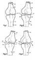
- FIG. 1is a schematic illustration depicting the spatial relationship between bones at a joint in a patient's body
- FIG. 2is a schematic illustration depicting the manner in which a wedge member is inserted into the joint between the bones of FIG. 1 to expand a portion of the joint and change the spatial relationship between the bones;
- FIG. 3is a schematic illustration of another embodiment of the invention in which the joint of FIG. 1 is flexed after the wedge member has been inserted into the joint and connected with only one of the bones;
- FIG. 4is a schematic illustration depicting an alternative manner of inserting the wedge member into the joint between the bones of FIG. 1 ;
- FIG. 5is a schematic pictorial illustration of the wedge member of FIGS. 2 and 3 ;
- FIG. 6is a plan view further illustrating the construction of the wedge member of FIG. 5 ;
- FIG. 7is a side view, taken generally along the line 7 - 7 of FIG. 6 , of the wedge member of FIG. 5 ;
- FIG. 8is an enlarged fragmentary schematic sectional view depicting the manner in which the wedge member of FIGS. 5-7 is positioned, as shown in FIG. 2 , in a joint between bones;
- FIG. 9is a fragmentary schematic sectional view, generally similar to FIG. 8 , but on a reduced scale, illustrating an embodiment of the invention in which the wedge member is porous;
- FIG. 10is a fragmentary schematic sectional view, generally similar to FIG. 9 , illustrating an embodiment of the wedge member which is porous and has a chamber which holds bone growth promoting material;
- FIG. 11is a fragmentary schematic sectional view, generally similar to FIGS. 8-10 , illustrating the manner in which the wedge member of FIG. 3 is connected with only one bone to enable the joint between bones to be flexed;
- FIG. 12is a schematic illustration depicting the manner in which a rotatable wedge member is moved into a joint between bones
- FIG. 13is a schematic illustration depicting the wedge member of FIG. 12 after the wedge member has been rotated to expand a portion of the joint between the bones;
- FIG. 14is an enlarged fragmentary schematic sectional view, taken generally along the line 14 - 14 of FIG. 12 , illustrating the relationship of the rotatable wedge member to the bones prior to rotation of the wedge member;
- FIG. 15is an enlarged fragmentary schematic sectional view, taken generally along the line 15 - 15 of FIG. 13 , illustrating the relationship of the rotatable wedge member of FIG. 14 to the bones after rotation of the wedge member;
- FIG. 16is a fragmentary schematic sectional view, taken generally along the line 16 - 16 of FIG. 15 , illustrating the manner in which the rotatable wedge member is connected with the bones;
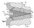
- FIG. 17is a fragmentary schematic sectional view, generally similar to FIG. 16 , illustrating an embodiment of the rotatable wedge member which is porous;
- FIG. 18is a fragmentary sectional view, generally similar to FIG. 14 , illustrating the relationship between the bones at a joint when another embodiment of the rotatable wedge member is in the initial orientation illustrated in FIG. 12 relative to the bones;
- FIG. 19is a fragmentary schematic sectional view, generally similar to FIG. 15 , illustrating the relationship of the rotatable wedge member of FIG. 18 to the bones after the wedge member has been rotated;
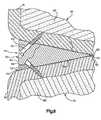
- FIG. 20is a fragmentary schematic sectional view, taken generally along the line 20 - 20 of FIG. 19 , further illustrating the construction of the rotatable wedge member;
- FIG. 21is a schematic illustration, generally similar to FIG. 2 , depicting the manner in which another embodiment of the rotatable wedge member is moved into a joint between bones in a patient's body;
- FIG. 22is an enlarged schematic pictorial illustration of the rotatable wedge member of FIG. 21 ;
- FIG. 23is a fragmentary schematic illustration, generally similar to FIG. 2 , depicting the manner in which another embodiment of the wedge member is moved into a joint between bones in a patient's body; and FIG. 24 is an enlarged fragmentary schematic sectional view, taken generally along the line 24 - 24 of FIG. 23 , further illustrating the relationship of the wedge member to the bones.
- FIG. 1An upper or first bone 30 in a patient's body is illustrated schematically in FIG. 1 .
- a lower or second bone 32is connected with the upper bone 30 at a joint 34 .
- the bones 30 and 32 and joint 34have been illustrated schematically to represent any one of many bones and joints in a patient's body.
- the bones 30 and 32 and joint 34may be disposed in a patient's hand, foot, back, or other portion of the patient's body.
- the bones 30 and 32 and joint 34have been illustrated schematically in FIG. 1 as being representative of any one of the many joints in a human patient's body and it is not intended to limit the present invention to any particular joint.
- an openingis formed in a portion of the patient's body to expose the joint 34 .
- a wedge member 44( FIG. 2 ) is moved into the exposed joint 34 between the bones 30 and 32 .
- the wedge member 44applies force against the outer side surfaces of the bones 30 and 32 at the joint 34 to expand a portion of the joint.
- the lower bone 32is pivoted relative to the upper bone 30 about an axis extending through the joint 34 .
- Thischanges the angular orientation of the lower bone 32 relative to the upper bone 30 .
- the spatial relationship between the upper and lower bones 30 and 32is changed from the spatial relationship illustrated in FIG. 1 to the spatial relationship illustrated in FIG. 2 by the wedge member 44 .
- the wedge member 44has been illustrated schematically as having an extent which corresponds to approximately one-half of the extent of the joint 34 .
- the wedge member 44could have an extent which is either smaller than or greater than the extent illustrated in FIG. 2 .
- the distance between the thick and thin end portions of the tapered wedge member 44may be less than one-half of the width of the joint 34 .
- the distance between the thin leading end portion and thick trailing end portion of the wedge member 44may be greater than one-half of the width of the joint 34 .
- the wedge member 44may be relatively narrow, as measured along the thin end portion of the wedge member. This would enable a plurality of narrow wedge members 44 to be used to expand a single joint 34 . If the wedge member 44 is relatively wide, only a single wedge member may be required to expand a joint 34 , as shown in FIG. 2 .
- the joint 34is fused after the joint has been expanded by the wedge member 44 to change the spatial relationship between the bones 30 and 32 .
- the jointis immobilized with the upper and lower bones 30 and 32 in the spatial relationship illustrated in FIG. 2 .
- the wedge member 44is utilized in association with joints between vertebrae in a patient's back, it is believed that it may be particularly advantageous to immobilize the joint 34 .
- Immobilization of the joint 34may be accomplished by connecting the wedge member 44 with both the upper bone 30 and the lower bone 32 . Immobilization of the joint 34 may also be accomplished by the growth of bone and/or other body tissue between the two bones 30 and 32 at the joint 34 .
- Known bone growth promoting materialsmay be provided at the joint 34 if desired.
- the bone growth promoting materialsmay include bone morphogenic proteins and/or other osteoinductive materials.
- the joint 34is capable of being flexed after the wedge member 44 has been utilized to expand a portion of the joint.
- the patientmay flex the joint under the influence of force transmitted to the bones 32 and 30 from muscle tissue in the patient's body.
- the bone 32moves away from the wedge member 44 .
- the wedge member 44is fixedly connected to only the bone 30 . This allows the bone 32 to move away from the wedge member. It is believed that it will be particularly advantageous to enable the joint 34 to be flexed when the wedge member is utilized to correct deformities occurring in hands, feet, wrists or ankles of a patient. However, it should be understood that the wedge member could be attached to a single bone at any joint in a patient's body which is to be flexed after the wedge member has been used to expand the joint.
- the wedge member 44has been shown as being moved into the joint 34 in a direction which is perpendicular to an axis about which the joint is flexed.
- the wedge member 44is moved into the joint 34 ( FIG. 2 ) in a direction perpendicular to the axis about which the joint 34 is schematically illustrated in FIG. 3 as being flexed.
- the wedge member 44is inserted into the joint 34 in a direction parallel to the axis about which the joint is normally flexed.
- the wedge member 44is illustrated in FIG. 4 as being inserted into the joint 34 in a direction perpendicular to the plane of the drawing of the joint 34 in FIGS. 1 and 3 .
- the wedge member 44could be inserted into a joint, such as the joint 34 , in any desired direction in order to obtain a desired expansion of the joint.
- the wedge member 44could be moved into the joint 34 along a path which is neither perpendicular to or parallel to the axis about which the joint is flexed.
- the opening in the patient's bodyis closed.
- the wedge member 44remains in the joint 34 between the bones 30 and 32 .
- the wedge member 44is formed of a rigid material which is capable of transmitting force between the bones 30 and 32 immediately after being positioned in the joint 34 . Therefore, the wedge member 44 is effective to maintain the changed spatial relationship, such as the spatial relationship illustrated in FIG. 2 , between the bones 30 and 32 during loading of the joint 34 immediately after positioning of the wedge member in the joint.
- the wedge member 44tapers from a thick end portion 50 to a thin end portion 52 .
- the wedge member 44has flat upper and lower major side surfaces 54 and 56 ( FIG. 7 ) which slope toward each other from the thick end portion 50 to the thin end portion 52 .
- the major side surfaces 54 and 56intersect at the thin end portion 52 .
- the pointed thin end portion 52 of the wedge member 44facilitates moving the wedge member into the joint 34 between the bones 30 and 32 ( FIG. 2 ).
- the thick end portion 50has an outer side surface 60 which forms a portion of a cylinder.
- the thin end portion 52extends diametrically across the cylinder ( FIG. 6 ). Therefore, the wedge member 44 has a semi-circular configuration.
- the configuration of the upper and lower major side surfaces 54 and 56 of the wedge member 44corresponds to the configuration of the joint with which the wedge member is to be associated.
- the semi-circular outer side surface 60will, for many joints at least, have an irregular configuration other than the semi-circular configuration illustrated in FIGS. 5 and 6 . This enables the outer side surface 60 to be aligned with the outer side surfaces of the bones 30 and 32 at the joint 34 . Since most bones do not have outer side surfaces which form portions of a semi-circular, it is believed that in all probability, the wedge member 44 will have an outer side surface 60 with an irregular configuration rather than the semi-circular configuration illustrated in FIG. 5 .
- the extent of the thin end portion 52 of the wedge member 44may be substantially less than shown in FIG. 6 .
- the extent of the thin end portion 52 of the wedge member 44may be less than one-half of the extent shown in FIG. 6 .
- Parallel triangular side surfaceswould extend between the outer side surface 50 of the wedge member 44 and opposite ends of the thin end portion 52 . These triangular side surfaces would be spaced from opposite sides of the joint 34 when the wedge member 44 is inserted into the joint.
- the wedge member 44When the wedge member 44 has a relatively narrow, generally U-shaped configuration, a plurality of the wedge members may be inserted into a single joint 34 ( FIG. 1 ). When a plurality of narrow wedge members 44 are used at one joint 34 , the wedge members may have different configurations. Thus, the wedge members 44 may have different lengths and/or different angles between the upper and lower major side surfaces 54 and 56 of the wedge members.
- the upper and lower major side surfaces 54 and 56 of the wedge member 44slope toward each other from the thick end portion 50 to the thin end portion 52 of the wedge member. It is contemplated that a plurality of wedge members 44 having different acute angles between the upper and lower major side surfaces 54 and 56 may be provided. This would enable a surgeon to select the wedge member 44 having a desired thickness at the thick end portion 50 . Thus, if a surgeon determines that a joint should be expanded to either a lesser or greater amount than would be accomplished by a wedge member having one angle, the surgeon may select a wedge member having a different angle and thickness to effect the desired expansion of the joint 34 . It is also contemplated that a plurality of wedge members 44 having different widths, as measured along the thin end portion 52 , may be provided.
- the acute angle between the flat upper and lower major side surfaces 54 and 56is determined by the extent to which the joint 34 is to be expanded, that is, the extent to which the spatial relationship between the bones 30 and 32 is to be changed by insertion of the wedge member 44 .
- the specific angle provided between the upper and lower major side surfaces 54 and 56 of the wedge member 44will vary depending upon the size of the joint with which the wedge member is used and the extent to which the spatial relationship between the bones 30 and 32 is to be changed by use of the wedge member.
- the length and width of the wedge member 44 inserted into a particular jointwill be determined by the extent to which the joint is to be expanded and the total number of wedge members to be inserted into the joint.
- the acute angle between the upper and lower major side surfaces 54 and 56 ( FIG. 6 ) of the wedge member 44may be desired to have the acute angle between the upper and lower major side surfaces 54 and 56 ( FIG. 6 ) of the wedge member 44 within a range between one and thirty degrees. Although it is difficult to be certain, it is believed that it may be preferred to have the acute angle between the upper and lower major side surfaces 54 and 56 of the wedge member 44 vary within a range of five degrees to twenty degrees. It should be understood that the foregoing specific ranges of sizes for the angle between the upper and lower major side surfaces 54 and 56 of the wedge member 44 have been set forth herein for purposes of clarity of description and it is contemplated that the angle between the upper and lower major side surfaces 54 and 56 may be any one of many angles other than these specific angles.
- a narrow wedge member 44may have a thin end portion 52 ( FIG. 6 ) with a length which is relatively small compared to the width of a joint.
- the thin end portion 52 of the narrow wedge member 44could have a length of less than one fourth the distance across the joint. This would result in opposite ends of the thin end portion 52 being spaced from the periphery of the joint. It is contemplated that a plurality of narrow wedge members 44 could be used to expand a single joint.
- the wedge member 44may be formed of any one of many different known materials which are compatible with a patient's body.
- the wedge membermay be formed of human or animal bone, stainless steel, tantalum, a porous ceramic, or a polymeric material. If desired, the wedge member may be formed of a biodegradable material. However, it is preferred to have the wedge member 44 formed of a rigid material which is capable of enabling force to be transmitted through the joint 34 between the bones 30 and 32 immediately after installation of the wedge member in the joint.
- the joint 34is immobilized.
- the wedge member 44is fixedly connected with the bone 30 and with the bone 32 .
- a pair of passages 64 and 66are formed in the wedge member 44 ( FIGS. 6 and 7 ).
- suitable fastenersthat is screws 70 and 72 extend through the passages 64 and 66 into the bones 30 and 32 in the manner indicated schematically in FIG. 8 .
- the screws 70 and 72engage hard cortical outer layers 76 and 78 of the bones 30 and 32 . If desired, the screws 70 and 72 could extend into the relatively soft cancellous bone 80 and 82 .
- the wedge member 44has been illustrated in FIG. 8 as being connected with the bones 30 and 32 by a pair of screws 70 and 72 , it should be understood that the wedge member 44 may be connected with only one of the bones 30 or 32 by only one of the screws 70 or 72 if desired.
- the joint 34could be flexed in the manner illustrated schematically in FIG. 3 , after the wedge member 44 has been moved into the joint.
- a location for insertion of the wedge member into the joint 34is selected by a surgeon.
- the specific location at which the wedge member 44 is inserted into the joint 34 to expand the jointwill be selected by the surgeon as a function of the desired result from a particular operation.
- the size of the wedge member 44will be selected by the surgeon as a function of the joint and the result to be obtained from a particular operation.
- the configuration of the wedge member 44will be selected by the surgeon as a function of the location where the wedge member is to be inserted into the joint 34 .
- the wedge member 44may be relatively wide and have a long thin end portion 52 , as shown in FIG. 6 , to enable the thin end portion to extend between opposite sides of the joint.
- the wedge member 44may be relatively narrow and have a thin end portion 52 which is short. If this is done, the thin end portion 52 would not extend between opposite sides of the joint 34 .
- a plurality of the narrow wedge members 44may be inserted into a single joint 34 to expand the joint and transmit force between the bones 30 and 32 .
- the surgeonmakes an incision in soft body tissue surrounding the joint 34 to expose the joint.
- the thin end portion 52 ( FIGS. 5 and 6 ) of the wedge member 44is moved into the joint 34 .
- the longitudinal central axis of the thin end portion 52 of the wedge memberis aligned with an axis about which the joint pivots.
- the wedge memberis then moved into the joint 34 along a linear path which extends perpendicular to the axis about which the joint pivots.
- the wedge member 44is moved into the joint 34 by applying force against the trailing thick end portion 50 of the wedge member.
- the upper major side surface 54 ( FIGS. 5 and 7 ) of the wedge memberslides along an outer side surface 88 ( FIG. 8 ) of the outer layer 76 of hard cortical bone.
- the lower major side surface 56 of the wedge member 44slides along an outer side surface 90 of the outer layer 78 of hard cortical bone.
- the outer side surfaces 88 and 90 of the bones 30 and 32are in their naturally occurring conditions. Thus, the outer side surfaces 88 and 90 of the bones 30 and 32 are not cut away to prepare for insertion of the wedge member 44 into the joint 34 . However, it should be understood that under certain circumstances that it may be necessary to abrade or otherwise cut the outer side surfaces 88 and 90 of the outer layers 76 and 78 of hard cortical bone to prepare the joint 34 for insertion of the wedge member 44 .
- the upper and lower major side surfaces 54 and 56apply force against the outer side surfaces 88 and 90 on the bones 30 and 32 .
- the joint 34is expanded.
- the bone 32is pivoted, relative to the bone 30 , from the initial orientation, shown in FIG. 1 , to the improved orientation shown in FIG. 2 .
- the longitudinal central axis 40 of the bone 32moves relative to the longitudinal central axis 38 of the bone 30 . Therefore, the angular relationship between the bones 30 and 32 is changed by expansion of a portion of the joint 34 by insertion of the wedge member 44 into the joint.
- the outer side surface 60 on the wedge membermoves slightly inward of the outer side surfaces on the bones 30 and 32 ( FIG. 8 ).
- the outer side surface 60 on the wedge member 44has a configuration which corresponds to the configurations of the outer side surfaces on the bones 30 and 32 adjacent to the joint 34 . Therefore, the wedge member 44 does not project outward from the joint. This minimizes any tendency of the wedge member to subsequently abrade body tissue adjacent to the joint 34 .
- the wedge member 44is fixedly connected with the bones 30 and 32 by the screws 70 and 72 to immobilize the joint.
- the area surrounding and directly adjacent to the wedge member 44is packed with bone growth promoting material and/or bone chips.
- the bone growth promoting materialsmay include bone morphogenic proteins and/or other osteoinductive materials. This promotes fusion of the bones 30 and 32 for remedial immobilization of the joint 34 .
- the wedge member 44Since the wedge member 44 is rigid, it can immediately transmit loads between the bones 30 and 32 . Therefore, after the incision which exposed the joint 34 has been closed, the patient can begin to load the joint 34 .
- the wedge member 44is effective to maintain the joint 34 in an expanded condition during loading of the joint. Therefore, the bones 30 and 32 remain in the improved spatial relationship illustrated in FIG. 2 during loading of the joint 34 .
- a solid wedge memberhas been utilized to expand the joint 34 .
- a porous wedge memberis utilized to expand a joint. Since the embodiment of the invention illustrated in FIG. 9 is generally similar to the embodiment of the invention illustrated in FIGS. 1-8 , similar numerals will be utilized to designate similar components, the suffix letter “a” being associated with the numerals of FIG. 9 in order to avoid confusion.
- a wedge member 44 ais positioned in a joint 34 a between bones 30 a and 32 a .
- the wedge member 44 aengages outer side surfaces 88 a and 90 a on layers 76 a and 78 a of hard cortical bone.
- the outer side surfaces 88 a and 90 aare in their naturally occurring conditions.
- suitable fasteners (screws) 70 a and 72 aare inserted through passages in the wedge member 44 a .
- the screws 70 a and 72 aengage the hard cortical outer layers 76 a and 78 a of bone to fixedly secure the wedge member 44 a with the bones 30 a and 32 a .
- passage 64widens proximate end portion 50 a configured to receive a head of fastener 70 a that is wider than a shaft of the fastener.
- a single wedge member 44 ais used to expand the joint 34 a .
- a plurality of narrow wedge members 44 amay be inserted into the joint at spaced apart locations about the periphery of the joint if desired.
- the wedge member 44 ais porous so that bone can grow through the wedge member. It is contemplated that the wedge member could be provided with a porous construction by having passages extend through the wedge member between the upper and lower major side surfaces 54 a and 56 a of the wedge member. The open ends of the passages would enable bone to grow through the wedge member 44 a.
- the wedge member 44 ais formed of a rigid open cell material.
- the open cell materialprovides cavities in which bone can grow through the wedge member 44 a .
- the wedge member 44 a( FIG. 9 ) has a cellular construction similar to coral.
- the wedge member 44 amay be coated with a material which promotes the growth of bone.
- the cells in the wedge member 44 amay be at least partially filled with bone growth promoting material.
- the bone growth promoting materialsmay be bone morphogenic proteins and other osteoinductive materials.
- the space around and adjacent to the wedge member 44 a in the joint 34 amay be packed with bone growth promoting material and/or bone chips.
- the wedge member 44 ais rigid and can be subject to normal loading immediately after being positioned in the joint 34 a . This enables the patient to subject the bones 30 a and 32 a to normal loading without waiting for fusion to occur through and around the wedge member 44 a . Of course, with the passage of time, the growth of bone through the wedge member 44 a and around the wedge member will strengthen the immobilization of the joint 34 a.
- the passages through the wedge member 44 aare formed by the open cell structure of the wedge member This results in the passages through the wedge member 44 a having an irregular configuration. If desired, linear passages could be formed in the wedge member 44 a . The linear passages may be drilled, cast, or formed in other ways in the wedge member 44 a.
- the wedge member 44is formed by a solid piece of material.
- the wedge member 44 ais formed by a continuous piece of porous material.
- the wedge memberis formed by a hollow piece of porous material. Since the embodiment of the invention illustrated in FIG. 10 is generally similar to the embodiments of the invention illustrated in FIGS. 1-9 , similar numerals will be utilized to designate similar components, the suffix letter “b” being associated with the numerals of FIG. 10 to avoid confusion.
- a wedge member 44 bis inserted into a joint 34 b between bones 30 b and 32 b to expand the joint. Expansion of the joint 34 b by the wedge member 44 b changes the spatial relationship between the bones 30 b and 32 b .
- the wedge member 44 bis held against movement relative to the bones 30 b and 32 b by fasteners (screws) 70 b and 72 b .
- the fasteners 70 b and 72 bextend through passages in the wedge member 44 b into layers 76 b and 78 b of hard cortical bone on bones 30 b , 32 b .
- the layers 76 b and 78 bare in their naturally occurring condition.
- a thin end portion 52 b of the wedge member 44 bis pressed into the joint 34 b by applying force against an outer side surface 60 b at a thick end portion 50 b of the wedge member 44 b .
- the force applied against the trailing thick end portion 50 b of the wedge member 44 bcauses flat upper and lower major side surfaces 54 b and 56 b to slide along outer side surfaces 88 b and 90 b .
- the wedge memberapplies force against the bones to expand the joint 34 b in the manner previously explained.
- the wedge member 44 b( FIG. 10 ) is hollow. Therefore, a compartment or cavity 100 is formed in the wedge member 44 b .
- the compartment 100has upper and lower inner side surfaces 102 and 104 which are smaller than the upper and lower major side surfaces 54 b and 56 b of the wedge member 44 b .
- the inner side surfaces 102 and 104 of the compartment 100have the same general configuration as the upper and lower major side surfaces 54 b and 56 b of the wedge member 44 b.
- the compartment 100is filled with bone growth inducing material 110 .
- the bone growth inducing material 110is positioned in the compartment 100 through a suitable opening (not shown) formed in either the upper major side surface 54 b or the lower major side surface 56 b of the wedge member 44 b .
- a suitable openingnot shown
- the wedge member 44 bis formed of a porous material which enables bone to grow through the wedge member.
- the growth of bone through the wedge member 44 bis promoted by the bone growth inducing material 110 in the compartment 100 .
- the bone growth inducing material 110 in the compartment 100may be any of many known bone morphogenic proteins and osteoinductive materials. For example, apatite compositions with collagen may be utilized. Demineralized bone powder may also be utilized. Regardless of which of the known bone growth inducing materials are selected, the presence of the bone growth promoting material 110 in the compartment 100 will promote a growth of bone through openings in the porous wedge member 44 b.
- the wedge member 44 bmay, itself, be formed of a suitable rigid material, such as tantalum, stainless steel, or ceramic materials.
- a suitable rigid materialsuch as tantalum, stainless steel, or ceramic materials.
- the surfaces of the wedge member 44 b and openings in the porous material of the wedge membermay be coated with suitable bone growth promoting materials.
- the wedge member 44 bis porous so that bone can grow through the wedge member.
- the wedge memberis formed of an open cell material having a construction similar to coral.
- the open cell materialprovides irregular passages which extend through the wedge member 44 b and enable the bone to grow through the wedge member.
- the wedge member 44 bcould be formed of a solid material with passages drilled or cast in the wedge member. Regardless of which of the materials the wedge member is formed, it is believed that it will be advantageous to have the material be sufficiently rigid to enable the joint 44 b to be load bearing immediately after an operation installing the wedge member in the joint.
- the wedge members 44 , 44 a , and 44 bare connected with bones on opposite sides of a joint by suitable fasteners (screws).
- the wedge memberis connected with only one of the bones. Since the embodiment of the invention illustrated in FIG. 11 is generally similar to the embodiments of the invention illustrated in FIGS. 1-10 , similar numerals will be utilized to designate similar components, the suffix letter “c” being associated with the numerals of FIG. 11 to avoid confusion.
- a wedge member 44 cis inserted into a joint 34 c between upper and lower bones 30 c and 32 c .
- the wedge member 44 chas the same general configuration and construction as the wedge member 44 of FIGS. 5-8 . However, the wedge member 44 c is connected with only one of the bones 30 c and 32 c . Thus, rather than utilizing a pair of fasteners to secure the wedge member 44 c to the upper and lower bones 30 c and 32 c , only a single fastener 70 c is utilized to connect the wedge member 44 c with the upper bone 30 c . Therefore, installation of the wedge member 44 c in the joint 34 c does not result in immobilization of the joint.
- the bone 32 cmay be moved away from the wedge member during flexing of the joint 34 c . This may result in the upper major side surface 54 c on the wedge member 54 c remaining in engagement with the outer side surface 88 c on the bone 30 c while the outer side surface 90 c on the bone 32 c moves away from the lower major side surface 56 c on the wedge member 44 c .
- a single fastener 70 cmay be utilized to hold the wedge member in the joint 34 c where the outer side surfaces 88 c and 90 c on the upper and lower bones 30 c and 32 c remain in engagement with the upper and lower major side surfaces 54 c and 56 c of the wedge member 44 c.
- the wedge member 44 c illustrated in FIG. 11the wedge member is formed of a solid material through which bone does not grow.
- a single fastenercorresponding to the fastener 70 c of FIG. 11 , may be used to connect a porous wedge member with a bone.
- bonemay grow through the porous wedge member.
- the porous wedge membermay have the same construction as shown in FIGS. 9 and 10 , with the exception of being held in place by only a single fastener 70 c.
- the wedge member 44is moved into the joint 34 between the upper and lower bones 30 and 32 along a linear path.
- the wedge member 44is moved into the joint 34 with the thin end portion 52 of the wedge member leading and the thick end portion 50 of the wedge member trailing.
- the tapered configuration of the wedge memberresults in the application of force against the upper and lower bones 30 and 32 to expand the joint 34 in the manner previously explained.
- the wedge memberis moved into the joint between the upper and lower bones and then rotated. During initial movement of the wedge member into the joint between the bones, there may be some expansion of the joint. During rotation of the wedge member in the joint, there is further expansion of the joint. Since the embodiment of the invention illustrated in FIGS. 12-15 is generally similar to the embodiments of the invention illustrated in FIGS. 1 -11 , similar numerals will be utilized to designate similar components, the suffix letter “d” being associated with the numerals of FIGS. 12-15 to avoid confusion.
- Upper and lower bones 30 d and 32 dare interconnected at a joint 34 d ( FIG. 12 ). Prior to insertion of a wedge member 44 d , the upper and lower bones 30 d and 32 d are in the same spatial orientation relative to each other as is illustrated in FIG. 1 . Upon insertion of the wedge member 44 d into the joint 34 d , in the manner illustrated in FIG. 12 , there may be a slight expansion of the joint 34 d and a slight change in the orientation of the upper bone 30 d relative to the lower bone 32 d .
- the wedge member 44 dAfter the wedge member 44 d has been inserted into the joint 34 d in the manner indicated schematically in FIG. 12 , the wedge member 44 d is rotated, through less than one revolution, about an axis 120 in the manner indicated schematically by an arrow 122 in FIG. 13 . As the wedge member 44 d is rotated through approximately ninety degrees about the axis 120 , the wedge member applies force against the upper and lower bones 30 d and 32 d to expand the joint 34 d . As the joint 34 d is expanded by rotation of the wedge member 44 d , the spatial relationship between the upper and lower bones 30 d and 32 d changes from the spatial relationship illustrated schematically in FIG. 12 to the spatial relationship illustrated schematically in FIG. 13 .
- the bones 30 d and 32 d illustrated schematically in FIGS. 12 and 13should be considered as being representative of bones at many different locations in a patient's body.
- the bones 30 d and 32 dmay be any of the many bones in a patient's wrist, ankle, hand, foot, back, or other portion of a patient's body.
- the bones 30 d and 32 dmay be vertebrae in a patient's back.
- the wedge member 44 dmay be used with any one of the many different types of joints in a patient's body.
- the wedge member 44 dhas a generally oval, cross-sectional configuration ( FIGS. 14 and 15 ), as viewed in a plane perpendicular to a longitudinal central axis of the wedge member.
- the wedge member 44 dhas an outer side surface 126 ( FIG. 14 ) with a pair of arcuate nose portions 128 and 130 .
- the arcuate nose portions 128 and 130 of the outer side surface 126are interconnected by a pair of arcuate side portions 134 and 136 .
- the arcuate outer side surface 126tapers from a thick end portion 50 d ( FIG. 16 ) to a thin end portion 52 d .
- the thin end portion 52 dis blunt or truncated.
- the thin end portion 52 d of the wedge member 44 ddoes not come to a sharp point as does the thin end portions of the wedge members 44 , 44 a , 44 b and 44 c.
- the wedge members 44 a , 44 b and 44 ccould be constructed with a blunt thin end portion corresponding to the blunt thin end portion 52 d ( FIG. 16 ) on the wedge member 44 d if desired.
- the wedge member 44 dcould be provided with a thin end portion 52 d ( FIG. 16 ) which comes to a sharp point in the same manner as the wedge members 44 , 44 a , 44 b and 44 c.
- the arcuate side portion 134engages the outer side surface 88 d of the upper bone 30 d and the arcuate side portion 136 engages the outer side surface 90 d of the lower bone 32 d .
- the arcuate side portions 134 and 136are relatively close together so that minimal expansion of the joint 34 d occurs when the wedge member 44 d is inserted into the joint.
- the arcuate side portions 134 and 136slide along and are effective to apply force against the outer side surfaces 88 d and 90 d of the upper and lower bones 30 d and 32 d to effect some expansion of the joint 34 d .
- the outer side surfaces 88 d and 90 d of the bones 30 d and 32 dare in their naturally occurring conditions.
- a suitable toolis inserted into a hexagonal socket 140 ( FIG. 14 ) in the wedge member 44 d .
- Torqueis transmitted from the tool to the wedge member 44 d to rotate the wedge member through less than one revolution in the direction indicated by the arrow 122 in FIGS. 13 and 15 .
- the wedge memberapplies force against the upper and lower bones 30 d and 32 d and expands the joint 34 d.
- the arcuate side portions 134 and 136slide along the outer side surfaces 88 d and 90 d on the bones.
- the arcuate nose portions 128 and 130 of the wedge member 44 dapproach the outer side surfaces 88 d and 90 d of the upper and lower bones 30 d and 32 d .
- the joint 34 dis expanded by the force applied against the upper and lower bones 30 d and 32 d by the wedge member 44 d .
- the arcuate nose portions 128 and 130engage the outer side surfaces 88 d and 90 d on the upper and lower bones 30 d and 32 d to hold the joint 34 d in the expanded condition illustrated in FIGS. 15 and 16 .
- a pair of mounting tabs 144 and 146are integrally formed with the wedge member 44 d .
- the mounting tabs 144 and 146project outwardly from the end portion 50 d of the wedge member 44 d .
- the mounting tabs 144 and 146are aligned with the arcuate nose portions 128 and 130 of the outer side surface 126 on the wedge member 44 d . Therefore, the mounting tabs 144 and 146 are disposed adjacent to the bones 30 d and 32 d in the manner illustrated schematically in FIG. 16 .
- a pair of retaining screws 70 d and 72 dextend through the mounting tabs 144 and 146 into the outer layers 76 d and 78 d of hard cancellous bone on the upper and lower bones 30 d and 32 d .
- the mounting screws or fasteners 70 d and 72 dare effective to hold the wedge member 44 d against rotation relative to the upper and lower bones 30 d and 32 d .
- Bone growth promoting material and/or bone chipsmay be packed in the joint 34 d around the wedge member 44 d .
- the wedge member 44 dis rigid and can transmit force between the bones 30 d and 32 d as soon as it is rotated to the position shown in FIGS. 15 and 16 .
- the wedge member 44 dis narrower than the distance across the joint 34 d . Therefore, a plurality of wedge members 44 d may be utilized to hold the joint 34 d in the expanded condition of FIGS. 15 and 16 .
- the plurality of wedge members 44 dcould be positioned in the joint 34 d with their rotational axes 120 ( FIG. 16 ) in a parallel relationship or with their rotational axes 120 skewed relative to each other. If a plurality of wedge members 44 d are utilized, they could be of different sizes or have different angles of taper along the axis 120 .
- wedge members 44 , 44 a , 44 b and 44 c of FIGS. 5-11could also be relatively narrow.
- a plurality of wedge members of FIGS. 5-11could be positioned in a joint with their longitudinal axes either parallel or skewed relative to each other.
- the wedge member 44 dis formed as a solid body of rigid material, such as stainless steel.
- the wedge member in the embodiment of the invention illustrated in FIG. 17is formed of a rigid porous material. Since the embodiment of the invention illustrated in FIG. 17 is generally similar to the embodiments of the invention illustrated in FIGS. 1-16 , similar numerals will be utilized to designate similar components, the suffix letter “e” being associated with the numerals of FIG. 17 to avoid confusion.
- the wedge member 44 eis disposed in a joint 34 e between upper and lower bones 30 e and 32 e .
- the wedge member 44 eapplies force against the outer side surfaces 88 e and 90 e of the upper and lower bones 30 e and 32 e to expand the joint 34 e and change the orientation of the upper and lower bones relative to each other.
- the wedge member 44 etapers from a thick end portion 50 e to a thin end portion 52 e .
- the thin end portion 52 e of the wedge member 44 ehas a pointed configuration rather than the blunt configuration of the wedge member 44 d of FIG. 16 .
- the wedge member 44 ecould have the same configuration as the wedge member 44 d if desired.
- the wedge member 44 e( FIG. 17 ) has an oval cross sectional configuration, as viewed on a plane extending perpendicular to a central axis 120 e of the wedge member 44 e .
- the wedge ember 44 ehas an outer side surface 126 e with arcuate nose portions 128 e and 130 e .
- the arcuate nose portions 128 e and 130are interconnected by arcuate side portions corresponding to the arcuate side portions 134 and 136 of the wedge member 44 d ( FIGS. 14 and 15 ).
- a socket 140 e( FIG. 17 ) is provided in the wedge member 44 e to facilitate the application of torque to the wedge member.
- the wedge member 44 eis formed of a rigid porous material having an open cell construction.
- the porous open cell construction of the wedge member 44 eenables bone to grow through the wedge member.
- the wedge member 44 emay have an open cell construction similar to the construction of coral.
- the wedge member 44 emay be coated with bone growth promoting materials to promote the growth of bone through the wedge member.
- the open cells in the porous wedge member 44 ecould be at least partially filled with the bone growth promoting material.
- bone growth materials and/or bone chipsmay be packed in the joint 34 e around the wedge member 44 e .
- the bone growth promoting materialsmay include bone morphogenic proteins and/or other osteoinductive materials.
- a pair of fasteners 70 e and 72 eare provided to connect the wedge member 44 e with the upper and lower bones 30 e and 32 e .
- the fasteners 70 eextends into the outer layer 76 e of hard cortical bone on the upper bone 30 e .
- the fastener 72 eextends into the outer layer 78 e of hard cortical bone on the lower bone 32 e .
- the fasteners 70 e and 72 eextend through passages in the wedge member 44 e into the upper and lower bones 30 e and 32 e .
- the wedge member 44 ecould be provided with mounting tabs, similar to the mounting tabs 144 and 146 of FIG. 16 .
- the wedge member 44 eWhen the wedge member 44 e is to be used to change the spatial relationship between the upper and lower bones 30 e and 32 e , the wedge member is inserted into the joint 34 e with the arcuate nose portions 128 e and 130 e of the wedge member spaced from the outer side surfaces 88 e and 90 e on the upper and lower bones 30 e and 32 e . At this time, the wedge member 44 e is in the same orientation as is illustrated in FIG. 14 for the wedge member 44 d . Arcuate side portions of the arcuate outer side surface 126 e on the wedge member 44 e engage the outer side surfaces 88 e and 90 e on the upper and lower bones 30 e and 32 e in the same manner as is illustrated for the wedge member 44 d in FIG. 14 .
- the wedge member 44 emay effect an initial, relatively small expansion of the joint, the majority of the expansion of the joint 34 e is obtained by rotating the wedge member 44 e about its central axis 120 e .
- a suitable toolis inserted into the socket 140 e . Force is transmitted from the tool to the wedge member 44 e to rotate the wedge member.
- the wedge memberAs the wedge member is rotated relative to the upper and lower bones 30 e and 32 e , the wedge member further expands the joint 34 e and effects further change in the spatial relationship between the upper and lower bones 30 e and 32 e.
- the wedge member 44 eis connected to the upper and lower bones 30 e and 32 e .
- the screws 70 e and 72 eare inserted through passages in the wedge member into the bone. Bone growth promoting material and/or bone chips may be packed in the joint 34 e around the wedge member 44 e.
- wedge members 44 eAlthough a single wedge member 44 e is utilized to expand the joint 34 e , a plurality of wedge members could be utilized if desired. When a plurality of wedge members 34 e are held to expand the joint 34 e , the wedge members may all be of the same size and configuration or may have different sizes and configurations.
- the wedge members 44 d and 44 eare rotated about their central axes 120 d and 120 e ( FIGS. 16 and 17 ) to effect expansion of the joints 34 d and 34 e .
- the wedge memberis rotated about a location where the wedge member engages one of the bones. Since the embodiment of the invention illustrated in FIGS. 18-20 is generally similar to the embodiments of the invention illustrated in FIGS. 1-17 , similar numerals will be utilized to designate similar components, the suffix letter “f” being associated with the numerals of FIGS. 18-20 to avoid confusion.
- Upper and lower bones 30 f and 32 fare interconnected at a joint 34 f .
- a wedge member 44 fis illustrated inserted into the joint 34 f between the upper and lower bones 30 f and 32 .
- the wedge member 44 fis positioned in the joint 34 f ( FIG. 18 ) with a relatively narrow width of the wedge member between outer side surfaces 88 f and 90 f on hard cortical outer layers 76 f and 78 f of the upper and lower bones 30 f and 32 f .
- outer side surfaces 88 f and 90 f of the upper and lower bones 30 f and 32 fare in their naturally occurring conditions, it is contemplated that a surgeon may want to prepare the surfaces of the bone for the wedge member 44 f by cutting away extraneous material to promote seating of the wedge member 44 f on the upper and lower bones 30 f and 32 f.
- the wedge member 44 fhas an arcuate nose portion 128 f and a pivot end portion 150 f .
- the nose portion 128 f and pivot end portion 150 fare interconnected by side portions 134 f and 136 f .
- the side portion 134 fhas a continuously curving arcuate configuration.
- the side portion 136 fmay have a linear configuration.
- the side portion 136 fhas a relatively flat area which engages the outer side surface 90 f on the lower bone 32 f when the wedge member 44 f is oriented as illustrated in FIG. 18 If desired, the side portion 136 f could have an arcuate configuration corresponding to the arcuate configuration of the side portion 134 f . If the side portion 136 f had the same configuration as the side portion 134 f , the wedge member 44 f would have a symmetrical configuration about an axis extending through the relatively sharply defined pivot end portion 150 c.
- the wedge member 44 fhas the same size and configuration throughout its length.
- the end portion 150 f of the wedge memberis the same size as the end portion 52 f ( FIG. 20 ).
- the wedge member 44 fcould taper from a relatively thick end portion 50 f to a relatively thin or small end portion 52 f in the manner illustrated in FIGS. 16 and 17 for the wedge members 44 d and 44 e .
- any one of the wedge members illustrated in FIGS. 1 through 17could be formed with the same configuration as the wedge member 44 f if desired.
- the wedge member 44 f( FIGS. 18 , 19 and 20 ) is formed of a rigid porous open cell material.
- the rigid porous open cell material of the wedge member 44 fhas a construction generally similar to coral.
- the wedge member 44 fcould be formed of a nonporous material if desired.
- the wedge member 44 fmay be formed of human or animal bone, metal, ceramic, or a polymeric material. While it may be preferred to form the wedge member 44 f of a porous material to enable bone to grow through the wedge member, the wedge member 44 f may be formed of a solid material through which bone can not grow.
- the wedge member 44 fmay be coated with or packed with bone growth promoting materials.
- the bone growth promoting materialsmay be bone morphogenic proteins and/or other osteoinductive materials.
- Bone chipsmay be included with the bone morphogenic proteins and/or other osteoinductive materials packed around the wedge member 44 f.
- the wedge member 44 fmay be provided with a tapered configuration to facilitate insertion into the joint 34 f .
- the wedge member 44 fis to be utilized to change the spatial relationship between the upper and lower bones 30 f and 32 f , the wedge member is inserted into the joint 34 f .
- the illustrated embodiment of the wedge member 44 fhas the same size and configuration throughout its length. Therefore, the wedge member 44 f does not taper to a thin end portion to facilitate insertion of the wedge member into the joint 34 f . Therefore, the joint 34 f may be initially expanded with a suitable tool to enable the wedge member 44 f to be inserted into the joint, in the orientation illustrated in FIG. 18 .
- the wedge member 44 fWhen the wedge member 44 f is inserted into the joint 34 f , there will be a slight initial expansion of the joint. As was previously mentioned, the wedge member 44 f may have an axially tapered configuration, similar to the configuration of the wedge members 44 d and 44 e ( FIGS. 16 and 17 ), to facilitate insertion of the wedge member 44 f into the joint 34 f.
- the side portions 1 34 f and 136 f on the wedge member 44 fslide along the outer side surfaces 88 f and 90 f on the upper and lower bones 30 f and 32 f .
- the arcuate nose portion 128 f of the wedge member 44 fis spaced from the outer side surface surfaces 88 f and 90 f of the upper and lower bones 30 f and 32 f.
- the wedge member 44 fis rotated about an axis extending through a location where the pivot end portion 150 f of the wedge member 44 f engages the outer side surface 90 f of the lower bone 32 f .
- a suitable toolis inserted into a socket 140 f . Force is transmitted through the tool to the wedge member 44 f urging the wedge member 44 f to rotate in a clockwise direction from the position shown in FIG. 18 to the position shown in FIG. 19 .
- the pivot end portion 150 f of the wedge member 44 fis pressed against the outer side surface 90 f of the lower bone 32 f .
- the side portion 134 f of the wedge member 44 fbegins to slide along the outer side surface 88 f on the upper bone 30 f.
- the wedge member 44 fWhen the wedge member 44 f reaches the orientation shown in FIG. 19 , the joint 34 f has been expanded to the maximum extent possible by the wedge member.
- the wedge member 44 fis then connected with the upper and lower bones 30 f and 32 f by suitable fasteners.
- the fastenersmay extend through mounting tabs, similar to the mounting tabs 144 and 146 illustrated in FIG. 16 or the fasteners may extend through the wedge member in the manner illustrated schematically in FIG. 17 .
- the wedge member 44 fcould be held in the upright (as viewed in FIG. 19 ) orientation in any one of many different manners by a suitable fastener arrangement.
- a plurality of the wedge members 44 fcould be used to expand the joint 34 f and to transmit force between the bones 30 f and 32 f .
- the jointmay be packed with bone growth promoting material.
- the wedge member 44 dhas a relatively smooth outer side surface 126 .
- the wedge memberhas a configuration similar to the configuration of a screw and has a irregular outer side surface. Since the embodiment of the invention illustrated in FIGS. 21 and 22 is generally similar to the embodiments of the invention illustrated in FIGS. 12-20 , similar numerals will be utilized to designate similar components, the suffix letter “g” being associated with the numerals of FIGS. 21 and 22 to avoid confusion.
- An upper bone 30 gis connected with a lower bone 32 g in a patient's body at a joint 34 g .
- the joint 34 ghas been illustrated schematically in FIG. 21 and may be any joint in a patient's body.
- a rigid wedge member 44 gis utilized to change the spatial relationship between the upper and lower bones 30 g and 32 g .
- the wedge member 44 gis effective to expand at least a portion of the joint 34 g when the wedge member 44 g is inserted into the joint 34 g.
- the wedge member 44 ghas a thick end portion 50 g and a thin end portion 52 g .
- the wedge member 44 ghas an overall conical configuration.
- An external thread convolution 160is formed on the wedge member 44 g .
- the external thread convolution 160has a spiral configuration and extends from the thick end portion 50 g to the thin end portion 52 g of the wedge member 44 g.
- the illustrated thread convolution 160could have many different configurations, the illustrated thread convolution has generally V-shaped crests and roots.
- the general configuration of the external thread convolution 160is an American National Form Screw Thread and has a pitch cone with an angle of between five degrees and twenty degrees.
- one specific external thread convolutionhas been illustrated and described herein, it should be understood that the external thread convolution 160 could have a configuration of any one of many different known thread convolutions. It is believed that it may be desired to use known bone screw thread configurations for the configuration of the external thread convolution 160 .
- the rigid wedge member 44 gmay be formed of metal, ceramic, human or animal bone, or suitable polymeric materials. It is believed that it will be desirable to form the wedge member 44 g of a material which is sufficiently rigid to withstand the forces transmitted between the upper and lower bones 30 g and 32 g . If desired, the wedge member 44 g may be formed of a porous material having openings through which bone may grow. It is believed that it may be desired to coat the wedge member 44 g with a bone growth promoting material.
- the wedge member 44 gWhen the wedge member 44 g is to be utilized to change the spatial relationship between the upper and lower bones 30 g and 32 g , the thin end portion 52 g of the wedge member 44 g is pressed into the joint 34 g between the upper and lower bones 30 g and 32 g . The wedge member 44 g is then rotated about its longitudinal central axis 120 g . A hexagonal recess 140 g is provided in the wedge member 44 g to facilitate the transmission of force from a suitable tool to the wedge member 44 g.
- the external thread convolution 160 gengages the upper and lower bones 30 g and 32 g .
- the external thread convolution 160engages the upper and lower bones 30 g and 32 g and pulls the wedge member into the joint 34 g .
- the joint 34 gis expanded and the spatial relationship between the upper and lower bones 30 g and 32 g is changed.
- the joint 34 gmay be packed with bone growth promoting materials and/or bone chips. It is contemplated that various known bone morphogenic proteins may be used with other osteoinductive materials to induce bone growth in the joint 34 g . Although only a single wedge member 44 g is illustrated in FIG. 21 , a plurality of wedge members may be used if desired.
- the wedge membershave flat upper and lower major side surfaces 54 and 56 ( FIG. 6 ).
- the wedge memberhas nonlinear side surfaces which have been shaped to correspond to the configuration of end portions of the bone at a joint between the bones. Since the embodiment of the invention illustrated in FIGS. 23 and 24 is generally similar to the embodiments of the invention illustrated in FIGS. 1-11 , similar numerals will be utilized to designate similar components, the suffix letter “h” being associated with the numerals of FIG. 9 to avoid confusion.
- Upper and lower bones 30 h and 32 hare interconnected at a joint 34 h .
- the joint 34 his a schematic representation of any one of many joints in a patient's body.
- the joint 34 hmay be in a patient's wrist, ankle, hand, foot, back, or other portion of the patient's body.
- a wedge member 44 his moved into the joint 34 h .
- the wedge member 44 his moved into the joint with a thick end portion 50 h of the wedge member trailing and a thin end portion 52 h of the wedge member leading.
- upper and lower major side surfaces 54 h and 56 hare pressed against outer side surfaces 88 h and 90 h on the upper and lower bones 30 h and 32 h . This results in expansion of the joint 34 h in the manner previously described in conjunction with the embodiments of the invention illustrated in FIGS. 1-11 .
- the upper and lower major side surfaces 54 h and 56 h on the wedge member 44 hare configured to match the configuration of the outer side surfaces 88 h and 90 h on the upper and lower bones 30 h and 32 h , in the manner illustrated schematically in FIG. 24 .
- the wedge member 44 his firmly seated against the bone and held against sidewise (as viewed in FIG. 24 ) movement relative to the bones.
- the arcuate configuration of the upper and lower major side surfaces 54 h and 56 h on the wedge member 44 hextends from the thick end 50 h of the wedge member 44 h to the thin end 52 h of the wedge member.
- the wedge member 44 his formed of a rigid porous material having an open cell construction.
- a compartment or cavity 100 h in the wedge member 44 hholds bone growth inducing materials 110 h .
- the bone growth inducing materials 110 hmay include bone morphogenic proteins and other osteoinductive materials.
- the joint 34 hmay be packed with bone growth promoting materials and/or bone chips.
- the wedge member 44 his fixedly connected to the upper and lower bones 30 h and 32 h by suitable fasteners (not shown).
- the wedge member 44 hmay be connected with the upper and lower bones 30 h and 32 h by screws corresponding to the screws 70 and 72 of FIG. 8 .
- the wedge member 44 hmay be connected with the upper and lower bone 30 h and 32 h by screws which extends through mounting tabs, corresponding to the mounting tabs 144 and 146 of FIG. 16 .
- the wedge member 44 hmay be connected with only the upper bone 30 h or only the lower bone 32 h.
- the joint 34 hwill be particularly stable when the joint has been immobilized by connecting the wedge member 44 h to the bones.
- a single wedge member 34 hhas been illustrated in FIGS. 22 and 24 , a plurality of wedge members could be used to expand the joint. It is believed that the wedge member 44 h may be particularly advantageous when vertebrae in a patient's back are to be interconnected.
- a new and improved method and apparatusis provided to change a spatial relationship between bones 30 and 32 which are interconnected at a joint 34 in a patient's body.
- an openingis formed in a portion of the patient's body to expose the joint 34 interconnecting the bones 30 and 32 .
- One of the bones 30 and 32is moved relative to the other by expanding at least a portion of the joint 34 with a wedge member 44 .
- the wedge member 44is moved into the joint and applies force against the bones 30 and 32 .
- the openingis closed with the wedge member 44 still disposed in the joint between the bones. Force is then transmitted between the bones 30 and 32 through the wedge member 44 to maintain the joint 34 in an expanded condition.
- the wedge membermay be connected with only one of the bones 30 and 32 .
- the wedge membermay be fixedly connected with the bones 30 and 32 interconnected at the joint.
- the wedge member 44may be porous and may be coated with and/or contain bone growth promoting material.
- One embodiment of the wedge member 44has major side surfaces 54 and 56 extending between thick and thin end portions 50 and 52 of the wedge member.
- the wedge member 44is moved into the joint 34 with the thin edge portion 52 leading.
- the thick trailing end portion 50 of the wedge memberexpands the joint.
- the wedge member 44 d , 44 e , 44 f , or 44 gmay be rotated relative to the joint.
- the wedge member 44 ghas a circular cross sectional configuration and has an external thread convolution 160 which extends from a thin leading end 52 g of the wedge member to a thick trailing end 50 g of the wedge member. The wedge member 44 g is pressed into the joint 34 g and rotated to cause the wedge member to expand the joint.
- the wedge member 44 d , 44 e or 44 fhas surface areas 134 and 136 which are relatively close together and other surface areas 128 and 130 which are relatively far apart.
- the wedge member 44 d , 44 e , or 44 fis moved into the joint 34 with the surface areas 134 and 136 which are close together engaging the adjacent bones 30 and 32 .
- the wedge member 44 d , 44 e or 44 fis then rotated to apply force against the adjacent bones to expand the joint.
- the wedge member 44 d or 44 emay be rotated about its central axis 120 to apply forced against the bones 30 and 32 and expand the joint.
- the wedge member 44 fmay be rotated about a location where the wedge member engages one of the bones.
- the wedge membermay be used with any one of the many different bones and joints in a patient's body.
- the wedge membermay be utilized at joints in a patient's wrist, ankle, hand, foot, back, or other portions of the patient's body.
- the use of the wedge membermay be particularly advantageous when a joint between vertebrae in a patient's back is to be immobilized.
- One or more wedge membersmay be used to expand a joint to transmit force between bones.
Landscapes
- Health & Medical Sciences (AREA)
- Engineering & Computer Science (AREA)
- Biomedical Technology (AREA)
- Orthopedic Medicine & Surgery (AREA)
- Life Sciences & Earth Sciences (AREA)
- Veterinary Medicine (AREA)
- Public Health (AREA)
- Heart & Thoracic Surgery (AREA)
- Animal Behavior & Ethology (AREA)
- General Health & Medical Sciences (AREA)
- Neurology (AREA)
- Cardiology (AREA)
- Transplantation (AREA)
- Oral & Maxillofacial Surgery (AREA)
- Vascular Medicine (AREA)
- Surgery (AREA)
- Pain & Pain Management (AREA)
- Rheumatology (AREA)
- Nuclear Medicine, Radiotherapy & Molecular Imaging (AREA)
- Medical Informatics (AREA)
- Molecular Biology (AREA)
- Prostheses (AREA)
- Surgical Instruments (AREA)
Abstract
Description
Claims (47)
Priority Applications (2)
| Application Number | Priority Date | Filing Date | Title |
|---|---|---|---|
| US10/755,996US9044341B2 (en) | 1998-08-20 | 2004-01-13 | Joint spacer |
| US14/711,937US20150238317A1 (en) | 1998-08-20 | 2015-05-14 | Joint spacer |
Applications Claiming Priority (4)
| Application Number | Priority Date | Filing Date | Title |
|---|---|---|---|
| US09/137,443US6099531A (en) | 1998-08-20 | 1998-08-20 | Changing relationship between bones |
| US09/569,020US6423063B1 (en) | 1998-08-20 | 2000-05-11 | Changing relationship between bones |
| US10/163,480US7780670B2 (en) | 1998-08-20 | 2002-06-05 | Changing relationship between bones |
| US10/755,996US9044341B2 (en) | 1998-08-20 | 2004-01-13 | Joint spacer |
Related Parent Applications (1)
| Application Number | Title | Priority Date | Filing Date |
|---|---|---|---|
| US10/163,480ContinuationUS7780670B2 (en) | 1998-08-20 | 2002-06-05 | Changing relationship between bones |
Related Child Applications (1)
| Application Number | Title | Priority Date | Filing Date |
|---|---|---|---|
| US14/711,937ContinuationUS20150238317A1 (en) | 1998-08-20 | 2015-05-14 | Joint spacer |
Publications (2)
| Publication Number | Publication Date |
|---|---|
| US20040254582A1 US20040254582A1 (en) | 2004-12-16 |
| US9044341B2true US9044341B2 (en) | 2015-06-02 |
Family
ID=22477458
Family Applications (9)
| Application Number | Title | Priority Date | Filing Date |
|---|---|---|---|
| US09/137,443Expired - LifetimeUS6099531A (en) | 1998-08-20 | 1998-08-20 | Changing relationship between bones |
| US09/569,020Expired - LifetimeUS6423063B1 (en) | 1998-08-20 | 2000-05-11 | Changing relationship between bones |
| US10/163,480Expired - Fee RelatedUS7780670B2 (en) | 1998-08-20 | 2002-06-05 | Changing relationship between bones |
| US10/755,996Expired - Fee RelatedUS9044341B2 (en) | 1998-08-20 | 2004-01-13 | Joint spacer |
| US10/756,001Expired - Fee RelatedUS7892261B2 (en) | 1998-08-20 | 2004-01-13 | Spinal implant and methods for changing spatial relationships between vertebrae |
| US10/755,995Expired - Fee RelatedUS7001385B2 (en) | 1998-08-20 | 2004-01-13 | Joint spacer with compartment for orthobiologic material |
| US11/928,262AbandonedUS20080058822A1 (en) | 1998-08-20 | 2007-10-30 | Joint spacer |
| US13/745,263Expired - Fee RelatedUS8956417B2 (en) | 1998-08-20 | 2013-01-18 | Joint spacer |
| US14/711,937AbandonedUS20150238317A1 (en) | 1998-08-20 | 2015-05-14 | Joint spacer |
Family Applications Before (3)
| Application Number | Title | Priority Date | Filing Date |
|---|---|---|---|
| US09/137,443Expired - LifetimeUS6099531A (en) | 1998-08-20 | 1998-08-20 | Changing relationship between bones |
| US09/569,020Expired - LifetimeUS6423063B1 (en) | 1998-08-20 | 2000-05-11 | Changing relationship between bones |
| US10/163,480Expired - Fee RelatedUS7780670B2 (en) | 1998-08-20 | 2002-06-05 | Changing relationship between bones |
Family Applications After (5)
| Application Number | Title | Priority Date | Filing Date |
|---|---|---|---|
| US10/756,001Expired - Fee RelatedUS7892261B2 (en) | 1998-08-20 | 2004-01-13 | Spinal implant and methods for changing spatial relationships between vertebrae |
| US10/755,995Expired - Fee RelatedUS7001385B2 (en) | 1998-08-20 | 2004-01-13 | Joint spacer with compartment for orthobiologic material |
| US11/928,262AbandonedUS20080058822A1 (en) | 1998-08-20 | 2007-10-30 | Joint spacer |
| US13/745,263Expired - Fee RelatedUS8956417B2 (en) | 1998-08-20 | 2013-01-18 | Joint spacer |
| US14/711,937AbandonedUS20150238317A1 (en) | 1998-08-20 | 2015-05-14 | Joint spacer |
Country Status (1)
| Country | Link |
|---|---|
| US (9) | US6099531A (en) |
Cited By (24)
| Publication number | Priority date | Publication date | Assignee | Title |
|---|---|---|---|---|
| US9237957B2 (en) | 2011-09-16 | 2016-01-19 | Globus Medical, Inc. | Low profile plate |
| US9358127B2 (en) | 2008-09-02 | 2016-06-07 | Globus Medical, Inc. | Intervertebral fusion implant |
| US9402738B2 (en) | 2013-02-14 | 2016-08-02 | Globus Medical, Inc. | Devices and methods for correcting vertebral misalignment |
| US9539109B2 (en) | 2011-09-16 | 2017-01-10 | Globus Medical, Inc. | Low profile plate |
| US9585765B2 (en) | 2013-02-14 | 2017-03-07 | Globus Medical, Inc | Devices and methods for correcting vertebral misalignment |
| US9615936B2 (en) | 2009-06-04 | 2017-04-11 | Globus Medical, Inc. | Intervertebral fusion implant |
| US9649198B2 (en) | 2011-04-29 | 2017-05-16 | Life Spine, Inc. | Spinal interbody implant with bone screw retention |
| US9681959B2 (en) | 2011-09-16 | 2017-06-20 | Globus Medical, Inc. | Low profile plate |
| US9730805B1 (en)* | 2008-03-27 | 2017-08-15 | Spinelogik, Inc. | Intervertebral fusion device and method or use |
| US9744049B2 (en) | 2007-11-16 | 2017-08-29 | DePuy Synthes Products, Inc. | Low profile intervertebral implant |
| US9848992B2 (en) | 2010-12-21 | 2017-12-26 | DePuy Synthes Products, Inc. | Intervertebral implants, systems, and methods of use |
| US9848994B2 (en) | 2011-09-16 | 2017-12-26 | Globus Medical, Inc. | Low profile plate |
| US9867718B2 (en) | 2014-10-22 | 2018-01-16 | DePuy Synthes Products, Inc. | Intervertebral implants, systems, and methods of use |
| US9877759B2 (en) | 2014-02-06 | 2018-01-30 | Life Spine, Inc. | Foot implant for bone fixation |
| US9889014B2 (en) | 2014-02-06 | 2018-02-13 | Life Spine, Inc. | Implant for bone fixation |
| US9895237B2 (en) | 2010-04-08 | 2018-02-20 | Globus Medical, Inc. | Intervertebral implant |
| US10064740B2 (en) | 2003-02-06 | 2018-09-04 | DePuy Synthes Products, LLC | Intervertebral implant |
| US10245155B2 (en) | 2011-09-16 | 2019-04-02 | Globus Medical, Inc. | Low profile plate |
| US10433976B2 (en) | 2008-11-07 | 2019-10-08 | DePuy Synthes Products, Inc. | Zero-profile interbody spacer and coupled plate assembly |
| US10492922B2 (en) | 2002-02-19 | 2019-12-03 | DePuy Synthes Products, Inc. | Intervertebral implant |
| US10512548B2 (en) | 2006-02-27 | 2019-12-24 | DePuy Synthes Products, Inc. | Intervertebral implant with fixation geometry |
| US20210244853A1 (en)* | 2015-05-06 | 2021-08-12 | Cartiheal (2009) Ltd. | Optimized solid substrates, tools for use with same and uses thereof for promoting cell and tissue growth |
| US11717417B2 (en) | 2011-09-16 | 2023-08-08 | Globus Medical Inc. | Low profile plate |
| US11730528B2 (en) | 2012-05-30 | 2023-08-22 | Globus Medical, Inc. | Aligning vertebral bodies |
Families Citing this family (596)
| Publication number | Priority date | Publication date | Assignee | Title |
|---|---|---|---|---|
| US6206922B1 (en)* | 1995-03-27 | 2001-03-27 | Sdgi Holdings, Inc. | Methods and instruments for interbody fusion |
| US5718717A (en) | 1996-08-19 | 1998-02-17 | Bonutti; Peter M. | Suture anchor |
| US6068630A (en) | 1997-01-02 | 2000-05-30 | St. Francis Medical Technologies, Inc. | Spine distraction implant |
| US7306628B2 (en) | 2002-10-29 | 2007-12-11 | St. Francis Medical Technologies | Interspinous process apparatus and method with a selectably expandable spacer |
| US7959652B2 (en) | 2005-04-18 | 2011-06-14 | Kyphon Sarl | Interspinous process implant having deployable wings and method of implantation |
| US7201751B2 (en) | 1997-01-02 | 2007-04-10 | St. Francis Medical Technologies, Inc. | Supplemental spine fixation device |
| US6045551A (en) | 1998-02-06 | 2000-04-04 | Bonutti; Peter M. | Bone suture |
| US6086593A (en) | 1998-06-30 | 2000-07-11 | Bonutti; Peter M. | Method and apparatus for use in operating on a bone |
| US6099531A (en)* | 1998-08-20 | 2000-08-08 | Bonutti; Peter M. | Changing relationship between bones |
| US6203546B1 (en)* | 1999-07-27 | 2001-03-20 | Macmahon Edward B | Method and apparatus for medial tibial osteotomy |
| FR2897259B1 (en) | 2006-02-15 | 2008-05-09 | Ldr Medical Soc Par Actions Si | INTERSOMATIC TRANSFORAMINAL CAGE WITH INTERBREBAL FUSION GRAFT AND CAGE IMPLANTATION INSTRUMENT |
| US6447516B1 (en) | 1999-08-09 | 2002-09-10 | Peter M. Bonutti | Method of securing tissue |
| US6368343B1 (en) | 2000-03-13 | 2002-04-09 | Peter M. Bonutti | Method of using ultrasonic vibration to secure body tissue |
| US6702821B2 (en) | 2000-01-14 | 2004-03-09 | The Bonutti 2003 Trust A | Instrumentation for minimally invasive joint replacement and methods for using same |
| US6770078B2 (en) | 2000-01-14 | 2004-08-03 | Peter M. Bonutti | Movable knee implant and methods therefor |
| US7635390B1 (en) | 2000-01-14 | 2009-12-22 | Marctec, Llc | Joint replacement component having a modular articulating surface |
| US6635073B2 (en) | 2000-05-03 | 2003-10-21 | Peter M. Bonutti | Method of securing body tissue |
| US7104996B2 (en) | 2000-01-14 | 2006-09-12 | Marctec. Llc | Method of performing surgery |
| US9138222B2 (en) | 2000-03-13 | 2015-09-22 | P Tech, Llc | Method and device for securing body tissue |
| US7094251B2 (en) | 2002-08-27 | 2006-08-22 | Marctec, Llc. | Apparatus and method for securing a suture |
| US8932330B2 (en) | 2000-03-13 | 2015-01-13 | P Tech, Llc | Method and device for securing body tissue |
| US6629998B1 (en)* | 2000-08-23 | 2003-10-07 | Chih-I Lin | Intervertebral retrieval device |
| US7166107B2 (en)* | 2000-09-11 | 2007-01-23 | D. Greg Anderson | Percutaneous technique and implant for expanding the spinal canal |
| US6358254B1 (en)* | 2000-09-11 | 2002-03-19 | D. Greg Anderson | Method and implant for expanding a spinal canal |
| US20020169507A1 (en) | 2000-12-14 | 2002-11-14 | David Malone | Interbody spine fusion cage |
| US6972019B2 (en)* | 2001-01-23 | 2005-12-06 | Michelson Gary K | Interbody spinal implant with trailing end adapted to receive bone screws |
| US6558387B2 (en)* | 2001-01-30 | 2003-05-06 | Fastemetix, Llc | Porous interbody fusion device having integrated polyaxial locking interference screws |
| DE60224850T2 (en)* | 2001-02-04 | 2009-01-22 | Warsaw Orthopedic, Inc., Warsaw | Instrumentation for introducing and positioning an expandable intervertebral fusion implant |
| CA2437575C (en)* | 2001-02-16 | 2009-04-07 | Queen's University At Kingston | Method and device for treating abnormal curvature of the spine |
| US20020120335A1 (en)* | 2001-02-28 | 2002-08-29 | Angelucci Christopher M. | Laminoplasty implants and methods of use |
| FR2824261B1 (en) | 2001-05-04 | 2004-05-28 | Ldr Medical | INTERVERTEBRAL DISC PROSTHESIS AND IMPLEMENTATION METHOD AND TOOLS |
| US6620199B2 (en)* | 2001-07-13 | 2003-09-16 | Ronald P. Grelsamer | Device for reinforcing bone in partial knee replacement surgery |
| FR2827156B1 (en) | 2001-07-13 | 2003-11-14 | Ldr Medical | VERTEBRAL CAGE DEVICE WITH MODULAR FASTENING |
| US6471725B1 (en)* | 2001-07-16 | 2002-10-29 | Third Millenium Engineering, Llc | Porous intervertebral distraction spacers |
| US7708741B1 (en) | 2001-08-28 | 2010-05-04 | Marctec, Llc | Method of preparing bones for knee replacement surgery |
| US6635087B2 (en) | 2001-08-29 | 2003-10-21 | Christopher M. Angelucci | Laminoplasty implants and methods of use |
| US20030105526A1 (en)* | 2001-11-30 | 2003-06-05 | Amei Technologies Inc. | High tibial osteotomy (HTO) wedge |
| US6719765B2 (en) | 2001-12-03 | 2004-04-13 | Bonutti 2003 Trust-A | Magnetic suturing system and method |
| US6733534B2 (en) | 2002-01-29 | 2004-05-11 | Sdgi Holdings, Inc. | System and method for spine spacing |
| US20100168751A1 (en)* | 2002-03-19 | 2010-07-01 | Anderson D Greg | Method, Implant & Instruments for Percutaneous Expansion of the Spinal Canal |
| US9155544B2 (en) | 2002-03-20 | 2015-10-13 | P Tech, Llc | Robotic systems and methods |
| DE20205016U1 (en)* | 2002-03-30 | 2003-08-14 | Mathys Medizinaltechnik Ag, Bettlach | Surgical implant |
| US6793678B2 (en) | 2002-06-27 | 2004-09-21 | Depuy Acromed, Inc. | Prosthetic intervertebral motion disc having dampening |
| US8048117B2 (en) | 2003-05-22 | 2011-11-01 | Kyphon Sarl | Interspinous process implant and method of implantation |
| US7497859B2 (en) | 2002-10-29 | 2009-03-03 | Kyphon Sarl | Tools for implanting an artificial vertebral disk |
| US7273496B2 (en) | 2002-10-29 | 2007-09-25 | St. Francis Medical Technologies, Inc. | Artificial vertebral disk replacement implant with crossbar spacer and method |
| US7931674B2 (en) | 2005-03-21 | 2011-04-26 | Kyphon Sarl | Interspinous process implant having deployable wing and method of implantation |
| US8070778B2 (en) | 2003-05-22 | 2011-12-06 | Kyphon Sarl | Interspinous process implant with slide-in distraction piece and method of implantation |
| US7549999B2 (en) | 2003-05-22 | 2009-06-23 | Kyphon Sarl | Interspinous process distraction implant and method of implantation |
| US7833246B2 (en) | 2002-10-29 | 2010-11-16 | Kyphon SÀRL | Interspinous process and sacrum implant and method |
| US7909853B2 (en) | 2004-09-23 | 2011-03-22 | Kyphon Sarl | Interspinous process implant including a binder and method of implantation |
| US6966929B2 (en) | 2002-10-29 | 2005-11-22 | St. Francis Medical Technologies, Inc. | Artificial vertebral disk replacement implant with a spacer |
| US7083649B2 (en) | 2002-10-29 | 2006-08-01 | St. Francis Medical Technologies, Inc. | Artificial vertebral disk replacement implant with translating pivot point |
| FR2846550B1 (en) | 2002-11-05 | 2006-01-13 | Ldr Medical | INTERVERTEBRAL DISC PROSTHESIS |
| US7192447B2 (en) | 2002-12-19 | 2007-03-20 | Synthes (Usa) | Intervertebral implant |
| US7887542B2 (en) | 2003-01-15 | 2011-02-15 | Biomet Manufacturing Corp. | Method and apparatus for less invasive knee resection |
| US7837690B2 (en) | 2003-01-15 | 2010-11-23 | Biomet Manufacturing Corp. | Method and apparatus for less invasive knee resection |
| US7789885B2 (en) | 2003-01-15 | 2010-09-07 | Biomet Manufacturing Corp. | Instrumentation for knee resection |
| US8551100B2 (en) | 2003-01-15 | 2013-10-08 | Biomet Manufacturing, Llc | Instrumentation for knee resection |
| AU2004212942A1 (en) | 2003-02-14 | 2004-09-02 | Depuy Spine, Inc. | In-situ formed intervertebral fusion device |
| WO2004084742A1 (en)* | 2003-03-24 | 2004-10-07 | Theken Surgical Llc | Spinal implant adjustment device |
| US7819903B2 (en) | 2003-03-31 | 2010-10-26 | Depuy Spine, Inc. | Spinal fixation plate |
| US7326251B2 (en)* | 2003-04-01 | 2008-02-05 | Sdgi Holdings, Inc. | Interbody fusion device |
| US7497864B2 (en) | 2003-04-30 | 2009-03-03 | Marctec, Llc. | Tissue fastener and methods for using same |
| US20070027547A1 (en)* | 2003-06-27 | 2007-02-01 | Advanced Bio Surfaces, Inc. | System and method for ankle arthroplasty |
| US20040267367A1 (en) | 2003-06-30 | 2004-12-30 | Depuy Acromed, Inc | Intervertebral implant with conformable endplate |
| US7753958B2 (en) | 2003-08-05 | 2010-07-13 | Gordon Charles R | Expandable intervertebral implant |
| US7708766B2 (en)* | 2003-08-11 | 2010-05-04 | Depuy Spine, Inc. | Distraction screw |
| US7520899B2 (en) | 2003-11-05 | 2009-04-21 | Kyphon Sarl | Laterally insertable artificial vertebral disk replacement implant with crossbar spacer |
| US7670377B2 (en) | 2003-11-21 | 2010-03-02 | Kyphon Sarl | Laterally insertable artifical vertebral disk replacement implant with curved spacer |
| US7481839B2 (en) | 2003-12-02 | 2009-01-27 | Kyphon Sarl | Bioresorbable interspinous process implant for use with intervertebral disk remediation or replacement implants and procedures |
| US20050154462A1 (en) | 2003-12-02 | 2005-07-14 | St. Francis Medical Technologies, Inc. | Laterally insertable artificial vertebral disk replacement implant with translating pivot point |
| US7488324B1 (en) | 2003-12-08 | 2009-02-10 | Biomet Manufacturing Corporation | Femoral guide for implanting a femoral knee prosthesis |
| WO2005058207A1 (en) | 2003-12-11 | 2005-06-30 | Isto Technologies, Inc. | Particulate cartilage system |
| US7621938B2 (en)* | 2004-01-15 | 2009-11-24 | Warsaw Orthopedic, Inc. | Spinal implant construct and method for implantation |
| EP2113227B1 (en) | 2004-02-04 | 2015-07-29 | LDR Medical | Intervertebral disc prosthesis |
| FR2865629B1 (en) | 2004-02-04 | 2007-01-26 | Ldr Medical | INTERVERTEBRAL DISC PROSTHESIS |
| JP2007521885A (en)* | 2004-02-05 | 2007-08-09 | オステオバイオロジックス, インコーポレイテッド | Absorbable orthopedic implant |
| US7846183B2 (en) | 2004-02-06 | 2010-12-07 | Spinal Elements, Inc. | Vertebral facet joint prosthesis and method of fixation |
| EP1713408B1 (en) | 2004-02-09 | 2010-09-15 | DePuy Spine, Inc. | Systems for spinal surgery |
| US20050197711A1 (en)* | 2004-03-03 | 2005-09-08 | Cachia Victor V. | Catheter deliverable foot implant and method of delivering the same |
| US20050229433A1 (en) | 2004-03-03 | 2005-10-20 | Cachia Victor V | Catheter deliverable foot implant and method of delivering the same |
| US8636802B2 (en) | 2004-03-06 | 2014-01-28 | DePuy Synthes Products, LLC | Dynamized interspinal implant |
| US20080039873A1 (en) | 2004-03-09 | 2008-02-14 | Marctec, Llc. | Method and device for securing body tissue |
| US7524324B2 (en) | 2004-04-28 | 2009-04-28 | Kyphon Sarl | System and method for an interspinous process implant as a supplement to a spine stabilization implant |
| FR2869528B1 (en) | 2004-04-28 | 2007-02-02 | Ldr Medical | INTERVERTEBRAL DISC PROSTHESIS |
| US7544208B1 (en) | 2004-05-03 | 2009-06-09 | Theken Spine, Llc | Adjustable corpectomy apparatus |
| US8083746B2 (en)* | 2004-05-07 | 2011-12-27 | Arthrex, Inc. | Open wedge osteotomy system and surgical method |
| US9504583B2 (en) | 2004-06-10 | 2016-11-29 | Spinal Elements, Inc. | Implant and method for facet immobilization |
| US20060129243A1 (en)* | 2004-09-21 | 2006-06-15 | Wong Hee K | Interbody spinal device |
| US8012209B2 (en) | 2004-09-23 | 2011-09-06 | Kyphon Sarl | Interspinous process implant including a binder, binder aligner and method of implantation |
| US7575600B2 (en) | 2004-09-29 | 2009-08-18 | Kyphon Sarl | Artificial vertebral disk replacement implant with translating articulation contact surface and method |
| US7481840B2 (en) | 2004-09-29 | 2009-01-27 | Kyphon Sarl | Multi-piece artificial spinal disk replacement device with selectably positioning articulating element |
| US7682393B2 (en)* | 2004-10-14 | 2010-03-23 | Warsaw Orthopedic, Inc. | Implant system, method, and instrument for augmentation or reconstruction of intervertebral disc |
| US9173647B2 (en) | 2004-10-26 | 2015-11-03 | P Tech, Llc | Tissue fixation system |
| US20060089646A1 (en) | 2004-10-26 | 2006-04-27 | Bonutti Peter M | Devices and methods for stabilizing tissue and implants |
| US9463012B2 (en) | 2004-10-26 | 2016-10-11 | P Tech, Llc | Apparatus for guiding and positioning an implant |
| US9271766B2 (en) | 2004-10-26 | 2016-03-01 | P Tech, Llc | Devices and methods for stabilizing tissue and implants |
| US20060111779A1 (en)* | 2004-11-22 | 2006-05-25 | Orthopedic Development Corporation, A Florida Corporation | Minimally invasive facet joint fusion |
| US8021392B2 (en)* | 2004-11-22 | 2011-09-20 | Minsurg International, Inc. | Methods and surgical kits for minimally-invasive facet joint fusion |
| US20060111786A1 (en)* | 2004-11-22 | 2006-05-25 | Orthopedic Development Corporation | Metallic prosthetic implant for use in minimally invasive acromio-clavicular shoulder joint hemi-arthroplasty |
| US20060111780A1 (en)* | 2004-11-22 | 2006-05-25 | Orthopedic Development Corporation | Minimally invasive facet joint hemi-arthroplasty |
| WO2006058221A2 (en) | 2004-11-24 | 2006-06-01 | Abdou Samy M | Devices and methods for inter-vertebral orthopedic device placement |
| US7879109B2 (en) | 2004-12-08 | 2011-02-01 | Biomet Manufacturing Corp. | Continuous phase composite for musculoskeletal repair |
| US20070038303A1 (en)* | 2006-08-15 | 2007-02-15 | Ebi, L.P. | Foot/ankle implant and associated method |
| US8535357B2 (en) | 2004-12-09 | 2013-09-17 | Biomet Sports Medicine, Llc | Continuous phase compositions for ACL repair |
| US8172877B2 (en)* | 2004-12-13 | 2012-05-08 | Kyphon Sarl | Inter-cervical facet implant with surface enhancements |
| US7776090B2 (en) | 2004-12-13 | 2010-08-17 | Warsaw Orthopedic, Inc. | Inter-cervical facet implant and method |
| US20070016196A1 (en)* | 2005-05-10 | 2007-01-18 | Winslow Charles J | Inter-cervical facet implant with implantation tool |
| US7763050B2 (en) | 2004-12-13 | 2010-07-27 | Warsaw Orthopedic, Inc. | Inter-cervical facet implant with locking screw and method |
| US8066749B2 (en)* | 2004-12-13 | 2011-11-29 | Warsaw Orthopedic, Inc. | Implant for stabilizing a bone graft during spinal fusion |
| US8128660B2 (en)* | 2004-12-13 | 2012-03-06 | Kyphon Sarl | Inter-cervical facet joint implant with locking screw system |
| US8029540B2 (en) | 2005-05-10 | 2011-10-04 | Kyphon Sarl | Inter-cervical facet implant with implantation tool |
| US8118838B2 (en)* | 2004-12-13 | 2012-02-21 | Kyphon Sarl | Inter-cervical facet implant with multiple direction articulation joint and method for implanting |
| FR2879436B1 (en) | 2004-12-22 | 2007-03-09 | Ldr Medical | INTERVERTEBRAL DISC PROSTHESIS |
| CH697330B1 (en) | 2004-12-28 | 2008-08-29 | Synthes Gmbh | Intervertebral prosthesis. |
| US8906026B2 (en) | 2005-01-31 | 2014-12-09 | Arthrex, Inc. | Method and apparatus for performing an open wedge, high tibial osteotomy |
| WO2008016687A2 (en)* | 2006-08-02 | 2008-02-07 | Ibalance Medical, Inc. | Method and apparatus for performing a high tibial, dome osteotomy |
| US7967823B2 (en)* | 2005-01-31 | 2011-06-28 | Arthrex, Inc. | Method and apparatus for performing an open wedge, high tibial osteotomy |
| US8496662B2 (en)* | 2005-01-31 | 2013-07-30 | Arthrex, Inc. | Method and apparatus for forming a wedge-like opening in a bone for an open wedge osteotomy |
| US7935119B2 (en) | 2005-01-31 | 2011-05-03 | Ibalance Medical, Inc. | Method for performing an open wedge, high tibial osteotomy |
| US8771279B2 (en) | 2005-01-31 | 2014-07-08 | Arthrex, Inc. | Method and apparatus for performing an osteotomy in bone |
| US8540777B2 (en)* | 2005-01-31 | 2013-09-24 | Arthrex, Inc. | Method and apparatus for performing an open wedge, high tibial osteotomy |
| CA2597228C (en)* | 2005-02-09 | 2014-07-22 | Ibalance Medical, Inc. | Multi-part implant for open wedge knee osteotomies |
| US9089323B2 (en) | 2005-02-22 | 2015-07-28 | P Tech, Llc | Device and method for securing body tissue |
| CA2603400C (en) | 2005-04-01 | 2015-11-24 | Ibalance Medical, Inc. | Method and apparatus for performing an open wedge, high tibial osteotomy |
| US20060276801A1 (en)* | 2005-04-04 | 2006-12-07 | Yerby Scott A | Inter-cervical facet implant distraction tool |
| ES2556111T3 (en) | 2005-04-08 | 2016-01-13 | Paradigm Spine, Llc | Interspinous vertebral and lumbosacral stabilization devices |
| US7695479B1 (en) | 2005-04-12 | 2010-04-13 | Biomet Manufacturing Corp. | Femoral sizer |
| US11903849B2 (en) | 2005-04-12 | 2024-02-20 | Moskowitz Family Llc | Intervertebral implant and tool assembly |
| US7942903B2 (en) | 2005-04-12 | 2011-05-17 | Moskowitz Ahmnon D | Bi-directional fixating transvertebral body screws and posterior cervical and lumbar interarticulating joint calibrated stapling devices for spinal fusion |
| US7674296B2 (en) | 2005-04-21 | 2010-03-09 | Globus Medical, Inc. | Expandable vertebral prosthesis |
| WO2007025290A2 (en) | 2005-08-26 | 2007-03-01 | Isto Technologies, Inc. | Implants and methods for repair, replacement and treatment of joint disease |
| US20070055380A1 (en)* | 2005-09-08 | 2007-03-08 | Biomet Manufacturing Corp | Method and apparatus for a glenoid prosthesis |
| FR2891135B1 (en) | 2005-09-23 | 2008-09-12 | Ldr Medical Sarl | INTERVERTEBRAL DISC PROSTHESIS |
| EP1942817B1 (en) | 2005-09-27 | 2014-05-07 | Paradigm Spine, LLC | Interspinous vertebral stabilization devices |
| FR2893838B1 (en) | 2005-11-30 | 2008-08-08 | Ldr Medical Soc Par Actions Si | PROSTHESIS OF INTERVERTEBRAL DISC AND INSTRUMENTATION OF INSERTION OF THE PROSTHESIS BETWEEN VERTEBRATES |
| CN101426455B (en)* | 2005-12-01 | 2011-11-23 | 阿特雷克斯公司 | Method and device for performing open wedge high tibial osteotomy |
| WO2007064950A2 (en)* | 2005-12-01 | 2007-06-07 | Ibalance Medical, Inc. | Open wedge, high bitial osteotomy method and apparatus |
| US8500778B2 (en)* | 2006-02-01 | 2013-08-06 | DePuy Synthes Products, LLC | Interspinous process spacer |
| US9439642B2 (en) | 2006-02-07 | 2016-09-13 | P Tech, Llc | Methods and devices for utilizing bondable materials |
| US11278331B2 (en) | 2006-02-07 | 2022-03-22 | P Tech Llc | Method and devices for intracorporeal bonding of implants with thermal energy |
| US7967820B2 (en) | 2006-02-07 | 2011-06-28 | P Tech, Llc. | Methods and devices for trauma welding |
| US11253296B2 (en) | 2006-02-07 | 2022-02-22 | P Tech, Llc | Methods and devices for intracorporeal bonding of implants with thermal energy |
| US8496657B2 (en) | 2006-02-07 | 2013-07-30 | P Tech, Llc. | Methods for utilizing vibratory energy to weld, stake and/or remove implants |
| US9011441B2 (en)* | 2006-02-17 | 2015-04-21 | Paradigm Spine, L.L.C. | Method and system for performing interspinous space preparation for receiving an implant |
| US20070198016A1 (en)* | 2006-02-21 | 2007-08-23 | Osteomed, L.P. | Compression stabilizing spacers |
| US9339278B2 (en) | 2006-02-27 | 2016-05-17 | Biomet Manufacturing, Llc | Patient-specific acetabular guides and associated instruments |
| US8298237B2 (en)* | 2006-06-09 | 2012-10-30 | Biomet Manufacturing Corp. | Patient-specific alignment guide for multiple incisions |
| US8092465B2 (en) | 2006-06-09 | 2012-01-10 | Biomet Manufacturing Corp. | Patient specific knee alignment guide and associated method |
| US8070752B2 (en) | 2006-02-27 | 2011-12-06 | Biomet Manufacturing Corp. | Patient specific alignment guide and inter-operative adjustment |
| US8608749B2 (en) | 2006-02-27 | 2013-12-17 | Biomet Manufacturing, Llc | Patient-specific acetabular guides and associated instruments |
| US8241293B2 (en)* | 2006-02-27 | 2012-08-14 | Biomet Manufacturing Corp. | Patient specific high tibia osteotomy |
| US7967868B2 (en) | 2007-04-17 | 2011-06-28 | Biomet Manufacturing Corp. | Patient-modified implant and associated method |
| US8608748B2 (en) | 2006-02-27 | 2013-12-17 | Biomet Manufacturing, Llc | Patient specific guides |
| US8282646B2 (en) | 2006-02-27 | 2012-10-09 | Biomet Manufacturing Corp. | Patient specific knee alignment guide and associated method |
| US9113971B2 (en)* | 2006-02-27 | 2015-08-25 | Biomet Manufacturing, Llc | Femoral acetabular impingement guide |
| US9907659B2 (en) | 2007-04-17 | 2018-03-06 | Biomet Manufacturing, Llc | Method and apparatus for manufacturing an implant |
| US8603180B2 (en) | 2006-02-27 | 2013-12-10 | Biomet Manufacturing, Llc | Patient-specific acetabular alignment guides |
| US10278711B2 (en) | 2006-02-27 | 2019-05-07 | Biomet Manufacturing, Llc | Patient-specific femoral guide |
| US9345548B2 (en) | 2006-02-27 | 2016-05-24 | Biomet Manufacturing, Llc | Patient-specific pre-operative planning |
| US8133234B2 (en) | 2006-02-27 | 2012-03-13 | Biomet Manufacturing Corp. | Patient specific acetabular guide and method |
| US8535387B2 (en)* | 2006-02-27 | 2013-09-17 | Biomet Manufacturing, Llc | Patient-specific tools and implants |
| US8591516B2 (en) | 2006-02-27 | 2013-11-26 | Biomet Manufacturing, Llc | Patient-specific orthopedic instruments |
| US8473305B2 (en) | 2007-04-17 | 2013-06-25 | Biomet Manufacturing Corp. | Method and apparatus for manufacturing an implant |
| US8858561B2 (en) | 2006-06-09 | 2014-10-14 | Blomet Manufacturing, LLC | Patient-specific alignment guide |
| US20110046735A1 (en)* | 2006-02-27 | 2011-02-24 | Biomet Manufacturing Corp. | Patient-Specific Implants |
| US8377066B2 (en) | 2006-02-27 | 2013-02-19 | Biomet Manufacturing Corp. | Patient-specific elbow guides and associated methods |
| US7780672B2 (en) | 2006-02-27 | 2010-08-24 | Biomet Manufacturing Corp. | Femoral adjustment device and associated method |
| US9289253B2 (en) | 2006-02-27 | 2016-03-22 | Biomet Manufacturing, Llc | Patient-specific shoulder guide |
| US9918740B2 (en) | 2006-02-27 | 2018-03-20 | Biomet Manufacturing, Llc | Backup surgical instrument system and method |
| US9173661B2 (en) | 2006-02-27 | 2015-11-03 | Biomet Manufacturing, Llc | Patient specific alignment guide with cutting surface and laser indicator |
| US20080257363A1 (en)* | 2007-04-17 | 2008-10-23 | Biomet Manufacturing Corp. | Method And Apparatus For Manufacturing An Implant |
| US8864769B2 (en) | 2006-02-27 | 2014-10-21 | Biomet Manufacturing, Llc | Alignment guides with patient-specific anchoring elements |
| US8568487B2 (en) | 2006-02-27 | 2013-10-29 | Biomet Manufacturing, Llc | Patient-specific hip joint devices |
| US20150335438A1 (en) | 2006-02-27 | 2015-11-26 | Biomet Manufacturing, Llc. | Patient-specific augments |
| US8407067B2 (en) | 2007-04-17 | 2013-03-26 | Biomet Manufacturing Corp. | Method and apparatus for manufacturing an implant |
| US20070233268A1 (en)* | 2006-03-31 | 2007-10-04 | Depuy Products, Inc. | Interpositional knee arthroplasty |
| DE102007018860B4 (en)* | 2006-04-28 | 2023-01-05 | Paradigm Spine L.L.C. | Instrument system for use with an interspinous implant |
| US11246638B2 (en) | 2006-05-03 | 2022-02-15 | P Tech, Llc | Methods and devices for utilizing bondable materials |
| US7695520B2 (en) | 2006-05-31 | 2010-04-13 | Biomet Manufacturing Corp. | Prosthesis and implementation system |
| US9795399B2 (en) | 2006-06-09 | 2017-10-24 | Biomet Manufacturing, Llc | Patient-specific knee alignment guide and associated method |
| US8560047B2 (en) | 2006-06-16 | 2013-10-15 | Board Of Regents Of The University Of Nebraska | Method and apparatus for computer aided surgery |
| WO2008019049A2 (en)* | 2006-08-03 | 2008-02-14 | Ibalance Medical Inc. | Method and apparatus for performing an open wedge, high tibial osteotomy |
| WO2008033489A2 (en)* | 2006-09-14 | 2008-03-20 | Life Spine, Inc. | Cervical and lumbar spinal interbody devices |
| WO2008039508A2 (en) | 2006-09-27 | 2008-04-03 | Ibalance Medical, Inc. | Method and apparatus for performing an open wedge, high tibial osteotomy |
| GB2442441B (en) | 2006-10-03 | 2011-11-09 | Biomet Uk Ltd | Surgical instrument |
| US20080161927A1 (en)* | 2006-10-18 | 2008-07-03 | Warsaw Orthopedic, Inc. | Intervertebral Implant with Porous Portions |
| US20080177311A1 (en)* | 2006-10-30 | 2008-07-24 | St. Francis Medical Technologies, Inc. | Facet joint implant sizing tool |
| US8409209B2 (en)* | 2006-11-22 | 2013-04-02 | Arthrex, Inc. | Method and apparatus for performing an open wedge, high tibial osteotomy |
| AR064013A1 (en)* | 2006-11-30 | 2009-03-04 | Paradigm Spine Llc | VERTEBRAL, INTERLAMINAR, INTERESPINOUS STABILIZATION SYSTEM |
| US20080208197A1 (en)* | 2006-11-30 | 2008-08-28 | Kelly Ammann | Method and apparatus for performing an open wedge, high tibial osteotomy |
| WO2008070027A2 (en)* | 2006-12-01 | 2008-06-12 | Ibalance Medical, Inc. | Method and apparatus for performing an open wedge, low femoral osteotomy |
| WO2008070863A2 (en) | 2006-12-07 | 2008-06-12 | Interventional Spine, Inc. | Intervertebral implant |
| US7871440B2 (en)* | 2006-12-11 | 2011-01-18 | Depuy Products, Inc. | Unitary surgical device and method |
| US8163549B2 (en) | 2006-12-20 | 2012-04-24 | Zimmer Orthobiologics, Inc. | Method of obtaining viable small tissue particles and use for tissue repair |
| US8821500B2 (en)* | 2006-12-20 | 2014-09-02 | Howmedica Osteonics Corp. | Femoral cutting block |
| US20080154374A1 (en)* | 2006-12-20 | 2008-06-26 | Robert David Labrom | Joint implant and a surgical method associated therewith |
| US9039768B2 (en) | 2006-12-22 | 2015-05-26 | Medos International Sarl | Composite vertebral spacers and instrument |
| US20080161929A1 (en) | 2006-12-29 | 2008-07-03 | Mccormack Bruce | Cervical distraction device |
| US7959677B2 (en) | 2007-01-19 | 2011-06-14 | Flexuspine, Inc. | Artificial functional spinal unit system and method for use |
| US8617185B2 (en) | 2007-02-13 | 2013-12-31 | P Tech, Llc. | Fixation device |
| US8465546B2 (en) | 2007-02-16 | 2013-06-18 | Ldr Medical | Intervertebral disc prosthesis insertion assemblies |
| US8992533B2 (en) | 2007-02-22 | 2015-03-31 | Spinal Elements, Inc. | Vertebral facet joint drill and method of use |
| EP2813190B1 (en) | 2007-02-22 | 2017-04-26 | Spinal Elements, Inc. | Vertebral facet joint drill |
| WO2008116203A2 (en) | 2007-03-22 | 2008-09-25 | Marctec, Llc | Methods and devices for intracorporeal bonding or interlocking of implants with thermal energy |
| US20090012612A1 (en)* | 2007-04-10 | 2009-01-08 | David White | Devices and methods for push-delivery of implants |
| US20090012629A1 (en) | 2007-04-12 | 2009-01-08 | Isto Technologies, Inc. | Compositions and methods for tissue repair |
| FI122996B (en)* | 2007-05-10 | 2012-09-28 | Teliasonera Ab | Processing of service request |
| FR2916956B1 (en) | 2007-06-08 | 2012-12-14 | Ldr Medical | INTERSOMATIC CAGE, INTERVERTEBRAL PROSTHESIS, ANCHORING DEVICE AND IMPLANTATION INSTRUMENTATION |
| US8900307B2 (en) | 2007-06-26 | 2014-12-02 | DePuy Synthes Products, LLC | Highly lordosed fusion cage |
| US20100131069A1 (en)* | 2007-08-01 | 2010-05-27 | Jeffrey Halbrecht | Method and system for patella tendon realignment |
| US20100198354A1 (en)* | 2007-08-01 | 2010-08-05 | Jeffrey Halbrecht | Method and system for patella tendon realignment |
| CA2698057A1 (en) | 2007-08-30 | 2009-03-05 | P Tech, Llc | Methods and devices for utilizing thermal energy to bond, stake and/or remove implants |
| US8328818B1 (en) | 2007-08-31 | 2012-12-11 | Globus Medical, Inc. | Devices and methods for treating bone |
| US20090088765A1 (en)* | 2007-09-27 | 2009-04-02 | Butler Michael S | Spinal Interbody Distractor |
| US8323322B2 (en)* | 2007-10-05 | 2012-12-04 | Zimmer Spine, Inc. | Medical implant formed from porous metal and method |
| US20090157190A1 (en)* | 2007-12-13 | 2009-06-18 | Howmedica Inc. | Osteotomy spacer |
| US20090177237A1 (en)* | 2008-01-04 | 2009-07-09 | Spartek Medical, Inc. | Cervical spine implant system and method |
| US20090177203A1 (en)* | 2008-01-04 | 2009-07-09 | Inbone Technologies, Inc. | Devices, systems and methods for re-alignment of bone |
| WO2009089367A2 (en) | 2008-01-09 | 2009-07-16 | Providence Medical Technology, Inc. | Methods and apparatus for accessing and treating the facet joint |
| EP2237748B1 (en) | 2008-01-17 | 2012-09-05 | Synthes GmbH | An expandable intervertebral implant |
| US8088163B1 (en) | 2008-02-06 | 2012-01-03 | Kleiner Jeffrey B | Tools and methods for spinal fusion |
| US20090248092A1 (en) | 2008-03-26 | 2009-10-01 | Jonathan Bellas | Posterior Intervertebral Disc Inserter and Expansion Techniques |
| US8936641B2 (en) | 2008-04-05 | 2015-01-20 | DePuy Synthes Products, LLC | Expandable intervertebral implant |
| US20210378834A1 (en) | 2008-05-22 | 2021-12-09 | Spinal Surgical Strategies, Inc., A Nevada Corporation D/B/A Kleiner Device Labs | Spinal fusion cage system with inserter |
| AU2009252835A1 (en)* | 2008-05-26 | 2009-12-03 | Medtech Research | Intersomatic cage |
| US7976578B2 (en)* | 2008-06-04 | 2011-07-12 | James Marvel | Buffer for a human joint and method of arthroscopically inserting |
| CA2725811A1 (en) | 2008-06-06 | 2009-12-10 | Providence Medical Technology, Inc. | Facet joint implants and delivery tools |
| US9333086B2 (en) | 2008-06-06 | 2016-05-10 | Providence Medical Technology, Inc. | Spinal facet cage implant |
| EP2361046B1 (en) | 2008-06-06 | 2019-04-24 | Providence Medical Technology, Inc. | Cervical distraction/implant delivery device |
| US11224521B2 (en) | 2008-06-06 | 2022-01-18 | Providence Medical Technology, Inc. | Cervical distraction/implant delivery device |
| US9381049B2 (en) | 2008-06-06 | 2016-07-05 | Providence Medical Technology, Inc. | Composite spinal facet implant with textured surfaces |
| US8267966B2 (en) | 2008-06-06 | 2012-09-18 | Providence Medical Technology, Inc. | Facet joint implants and delivery tools |
| US8361152B2 (en) | 2008-06-06 | 2013-01-29 | Providence Medical Technology, Inc. | Facet joint implants and delivery tools |
| EP2339976B1 (en) | 2008-07-09 | 2016-03-16 | Icon Orthopaedic Concepts, LLC | Ankle arthrodesis nail and outrigger assembly |
| US8414584B2 (en) | 2008-07-09 | 2013-04-09 | Icon Orthopaedic Concepts, Llc | Ankle arthrodesis nail and outrigger assembly |
| US9808345B2 (en) | 2008-07-24 | 2017-11-07 | Iorthopedics, Inc. | Resilient arthroplasty device |
| EP2339985A4 (en)* | 2008-09-12 | 2013-07-03 | Articulinx Inc | Tether-based orthopedic joint device delivery methods |
| US8137405B2 (en) | 2008-10-08 | 2012-03-20 | K2M, Inc. | Spinal interbody spacer |
| US20140012322A1 (en)* | 2008-10-10 | 2014-01-09 | Brian Gayvey | Bone Screw |
| WO2010045491A1 (en)* | 2008-10-15 | 2010-04-22 | Replication Medical, Inc. | Swellable interspinous stabilization implant |
| US8366748B2 (en) | 2008-12-05 | 2013-02-05 | Kleiner Jeffrey | Apparatus and method of spinal implant and fusion |
| US9247943B1 (en) | 2009-02-06 | 2016-02-02 | Kleiner Intellectual Property, Llc | Devices and methods for preparing an intervertebral workspace |
| US20100234905A1 (en)* | 2009-03-13 | 2010-09-16 | John Sledge | Facet joint resurfacing implant and associated surgical methods |
| WO2010107692A1 (en) | 2009-03-16 | 2010-09-23 | Synthes Usa, Llc | System and method for stabilizing vertebrae in spine surgery through a lateral access channel |
| US9526620B2 (en) | 2009-03-30 | 2016-12-27 | DePuy Synthes Products, Inc. | Zero profile spinal fusion cage |
| US8641766B2 (en)* | 2009-04-15 | 2014-02-04 | DePuy Synthes Products, LLC | Arcuate fixation member |
| US9408715B2 (en) | 2009-04-15 | 2016-08-09 | DePuy Synthes Products, Inc. | Arcuate fixation member |
| US9005301B2 (en)* | 2009-04-29 | 2015-04-14 | Foot Innovations, Llc | System and method for modifying talocalcaneal relationship in a foot |
| KR101687435B1 (en) | 2009-07-06 | 2016-12-19 | 신세스 게엠바하 | Expandable fixation assemblies |
| US9399086B2 (en)* | 2009-07-24 | 2016-07-26 | Warsaw Orthopedic, Inc | Implantable medical devices |
| US8641765B2 (en)* | 2009-08-12 | 2014-02-04 | Nabil L. Muhanna | Posterior spinal implant system |
| DE102009028503B4 (en) | 2009-08-13 | 2013-11-14 | Biomet Manufacturing Corp. | Resection template for the resection of bones, method for producing such a resection template and operation set for performing knee joint surgery |
| US10349980B2 (en) | 2009-08-27 | 2019-07-16 | The Foundry, Llc | Method and apparatus for altering biomechanics of the shoulder |
| US9668868B2 (en) | 2009-08-27 | 2017-06-06 | Cotera, Inc. | Apparatus and methods for treatment of patellofemoral conditions |
| US9278004B2 (en) | 2009-08-27 | 2016-03-08 | Cotera, Inc. | Method and apparatus for altering biomechanics of the articular joints |
| US9861408B2 (en) | 2009-08-27 | 2018-01-09 | The Foundry, Llc | Method and apparatus for treating canine cruciate ligament disease |
| CA2771332C (en) | 2009-08-27 | 2020-11-10 | Cotera, Inc. | Method and apparatus for force redistribution in articular joints |
| JP2013504389A (en) | 2009-09-11 | 2013-02-07 | アーティキュリンクス, インコーポレイテッド | Disc-shaped orthopedic device |
| CN105326585B (en) | 2009-09-17 | 2018-12-11 | Ldr控股公司 | Intervertebral implant with extensible bone anchoring element |
| US9629729B2 (en) | 2009-09-18 | 2017-04-25 | Spinal Surgical Strategies, Llc | Biological delivery system with adaptable fusion cage interface |
| USD750249S1 (en)* | 2014-10-20 | 2016-02-23 | Spinal Surgical Strategies, Llc | Expandable fusion cage |
| US8906028B2 (en) | 2009-09-18 | 2014-12-09 | Spinal Surgical Strategies, Llc | Bone graft delivery device and method of using the same |
| US10973656B2 (en) | 2009-09-18 | 2021-04-13 | Spinal Surgical Strategies, Inc. | Bone graft delivery system and method for using same |
| USD789539S1 (en) | 2015-07-09 | 2017-06-13 | Spinal Surgical Strategies, Llc | Fusion cage |
| US10245159B1 (en) | 2009-09-18 | 2019-04-02 | Spinal Surgical Strategies, Llc | Bone graft delivery system and method for using same |
| US20170238984A1 (en) | 2009-09-18 | 2017-08-24 | Spinal Surgical Strategies, Llc | Bone graft delivery device with positioning handle |
| US11103366B2 (en) | 2009-10-15 | 2021-08-31 | Globus Medical, Inc. | Expandable fusion device and method of installation thereof |
| US10806596B2 (en) | 2009-10-15 | 2020-10-20 | Globus Medical, Inc. | Expandable fusion device and method installation thereof |
| US9216095B2 (en) | 2009-10-15 | 2015-12-22 | Globus Medical, Inc. | Expandable fusion device and method of installation thereof |
| US8062375B2 (en) | 2009-10-15 | 2011-11-22 | Globus Medical, Inc. | Expandable fusion device and method of installation thereof |
| US11564807B2 (en) | 2009-10-15 | 2023-01-31 | Globus Medical, Inc. | Expandable fusion device and method of installation thereof |
| US8679183B2 (en) | 2010-06-25 | 2014-03-25 | Globus Medical | Expandable fusion device and method of installation thereof |
| US8685098B2 (en) | 2010-06-25 | 2014-04-01 | Globus Medical, Inc. | Expandable fusion device and method of installation thereof |
| US8556979B2 (en) | 2009-10-15 | 2013-10-15 | Globus Medical, Inc. | Expandable fusion device and method of installation thereof |
| US10098758B2 (en) | 2009-10-15 | 2018-10-16 | Globus Medical, Inc. | Expandable fusion device and method of installation thereof |
| US9155628B2 (en) | 2009-10-15 | 2015-10-13 | Globus Medical, Inc. | Expandable fusion device and method of installation thereof |
| US11344430B2 (en) | 2009-10-15 | 2022-05-31 | Globus Medical, Inc. | Expandable fusion device and method of installation thereof |
| US10327917B2 (en) | 2009-10-15 | 2019-06-25 | Globus Medical, Inc. | Expandable fusion device and method of installation thereof |
| US8709086B2 (en) | 2009-10-15 | 2014-04-29 | Globus Medical, Inc. | Expandable fusion device and method of installation thereof |
| US9028553B2 (en) | 2009-11-05 | 2015-05-12 | DePuy Synthes Products, Inc. | Self-pivoting spinal implant and associated instrumentation |
| WO2011057079A1 (en) | 2009-11-05 | 2011-05-12 | K2M, Inc. | Semi-constrained bone screw |
| WO2011057181A1 (en) | 2009-11-09 | 2011-05-12 | Centinel Spine, Inc. | Spinal implant configured for lateral insertion |
| US8840668B1 (en) | 2009-11-11 | 2014-09-23 | Nuvasive, Inc. | Spinal implants, instruments and related methods |
| US8740983B1 (en)* | 2009-11-11 | 2014-06-03 | Nuvasive, Inc. | Spinal fusion implants and related methods |
| US8764806B2 (en) | 2009-12-07 | 2014-07-01 | Samy Abdou | Devices and methods for minimally invasive spinal stabilization and instrumentation |
| US9393129B2 (en) | 2009-12-10 | 2016-07-19 | DePuy Synthes Products, Inc. | Bellows-like expandable interbody fusion cage |
| WO2011080535A1 (en) | 2009-12-31 | 2011-07-07 | Lrd Medical | Anchoring device, intervertebral implant and implantation instrument |
| US8353963B2 (en) | 2010-01-12 | 2013-01-15 | Globus Medical | Expandable spacer and method for use thereof |
| US10307257B2 (en) | 2010-01-22 | 2019-06-04 | Iorthopedics, Inc. | Resilient knee implant and methods |
| WO2013033447A2 (en) | 2011-09-01 | 2013-03-07 | Grotz R Thomas | Resilient interpositional arthroplasty device |
| WO2011091005A2 (en) | 2010-01-22 | 2011-07-28 | Grotz R Thomas | Resilient knee implant and methods |
| US8444699B2 (en)* | 2010-02-18 | 2013-05-21 | Biomet Manufacturing Corp. | Method and apparatus for augmenting bone defects |
| US9913726B2 (en) | 2010-02-24 | 2018-03-13 | Globus Medical, Inc. | Expandable intervertebral spacer and method of posterior insertion thereof |
| US8632547B2 (en) | 2010-02-26 | 2014-01-21 | Biomet Sports Medicine, Llc | Patient-specific osteotomy devices and methods |
| EP2547292B1 (en) | 2010-03-16 | 2019-04-24 | Pinnacle Spine Group, LLC | Ntervertebral implants and graft delivery systems |
| EP2547273A4 (en)* | 2010-03-19 | 2014-10-29 | Josef Gorek | ANTERIOR SUPPORT FOR SPINAL FASTENING |
| WO2011126825A2 (en) | 2010-03-29 | 2011-10-13 | Anderson D Greg | Device and method for expanding the spinal canal with spinal column stabilization and spinal deformity correction |
| US8870880B2 (en) | 2010-04-12 | 2014-10-28 | Globus Medical, Inc. | Angling inserter tool for expandable vertebral implant |
| US9301850B2 (en) | 2010-04-12 | 2016-04-05 | Globus Medical, Inc. | Expandable vertebral implant |
| US8647369B2 (en) | 2010-05-19 | 2014-02-11 | Josef E. Gorek | Minimal profile anterior bracket for spinal fixation |
| US9907560B2 (en) | 2010-06-24 | 2018-03-06 | DePuy Synthes Products, Inc. | Flexible vertebral body shavers |
| US8979860B2 (en) | 2010-06-24 | 2015-03-17 | DePuy Synthes Products. LLC | Enhanced cage insertion device |
| US9597200B2 (en) | 2010-06-25 | 2017-03-21 | Globus Medical, Inc | Expandable fusion device and method of installation thereof |
| US8623091B2 (en) | 2010-06-29 | 2014-01-07 | DePuy Synthes Products, LLC | Distractible intervertebral implant |
| US10709573B2 (en) | 2010-09-03 | 2020-07-14 | Globus Medical Inc. | Expandable fusion device and method of installation thereof |
| US9566168B2 (en) | 2010-09-03 | 2017-02-14 | Globus Medical, Inc. | Expandable fusion device and method of installation thereof |
| US8845731B2 (en) | 2010-09-03 | 2014-09-30 | Globus Medical, Inc. | Expandable fusion device and method of installation thereof |
| US8845734B2 (en) | 2010-09-03 | 2014-09-30 | Globus Medical, Inc. | Expandable fusion device and method of installation thereof |
| US10945858B2 (en) | 2010-09-03 | 2021-03-16 | Globus Medical, Inc. | Expandable interspinous process fixation device |
| US9351848B2 (en) | 2010-09-03 | 2016-05-31 | Globus Medical, Inc. | Expandable fusion device and method of installation thereof |
| US8491659B2 (en) | 2010-09-03 | 2013-07-23 | Globus Medical, Inc. | Expandable fusion device and method of installation thereof |
| US10085849B2 (en) | 2010-09-03 | 2018-10-02 | Globus Medical, Inc. | Expandable fusion device and method of installation thereof |
| US8632595B2 (en) | 2010-09-03 | 2014-01-21 | Globus Medical, Inc. | Expandable fusion device and method of installation thereof |
| US8435298B2 (en) | 2010-09-03 | 2013-05-07 | Globus Medical, Inc. | Expandable fusion device and method of installation thereof |
| US10758367B2 (en) | 2010-09-03 | 2020-09-01 | Globus Medical Inc. | Expandable fusion device and method of installation thereof |
| US10835387B2 (en) | 2010-09-03 | 2020-11-17 | Globus Medical Inc. | Expandable fusion device and method of installation thereof |
| US10842644B2 (en) | 2010-09-03 | 2020-11-24 | Globus Medical, Inc. | Expandable fusion device and method of installation thereof |
| US9474625B2 (en) | 2010-09-03 | 2016-10-25 | Globus Medical, Inc | Expandable fusion device and method of installation thereof |
| US9907673B2 (en) | 2010-09-03 | 2018-03-06 | Globus Medical, Inc. | Expandable fusion device and method of installation thereof |
| US8845732B2 (en) | 2010-09-03 | 2014-09-30 | Globus Medical, Inc. | Expandable fusion device and method of installation thereof |
| US11793654B2 (en) | 2010-09-03 | 2023-10-24 | Globus Medical, Inc. | Expandable fusion device and method of installation thereof |
| US12370057B2 (en) | 2010-09-03 | 2025-07-29 | Globus Medical, Inc. | Expandable fusion device and method of installation thereof |
| US12059358B2 (en) | 2010-09-03 | 2024-08-13 | Globus Medical Inc. | Expandable fusion device and method of installation thereof |
| US10869768B2 (en) | 2010-09-03 | 2020-12-22 | Globus Medical Inc. | Expandable fusion device and method of installation thereof |
| US10512550B2 (en) | 2010-09-03 | 2019-12-24 | Globus Medical, Inc. | Expandable interspinous process fixation device |
| US10779957B2 (en) | 2010-09-03 | 2020-09-22 | Globus Medical, Inc. | Expandable fusion device and method of installation thereof |
| US9855151B2 (en) | 2010-09-03 | 2018-01-02 | Globus Medical, Inc | Expandable fusion device and method of installation thereof |
| US8852279B2 (en) | 2010-09-03 | 2014-10-07 | Globus Medical, Inc. | Expandable fusion device and method of installation thereof |
| US11446162B2 (en) | 2010-09-03 | 2022-09-20 | Globus Medical, Inc. | Expandable fusion device and method of installation thereof |
| US8727203B2 (en) | 2010-09-16 | 2014-05-20 | Howmedica Osteonics Corp. | Methods for manufacturing porous orthopaedic implants |
| US11529241B2 (en)* | 2010-09-23 | 2022-12-20 | DePuy Synthes Products, Inc. | Fusion cage with in-line single piece fixation |
| US20120078372A1 (en) | 2010-09-23 | 2012-03-29 | Thomas Gamache | Novel implant inserter having a laterally-extending dovetail engagement feature |
| US20120078373A1 (en) | 2010-09-23 | 2012-03-29 | Thomas Gamache | Stand alone intervertebral fusion device |
| US9271744B2 (en) | 2010-09-29 | 2016-03-01 | Biomet Manufacturing, Llc | Patient-specific guide for partial acetabular socket replacement |
| US9402732B2 (en) | 2010-10-11 | 2016-08-02 | DePuy Synthes Products, Inc. | Expandable interspinous process spacer implant |
| US9968376B2 (en) | 2010-11-29 | 2018-05-15 | Biomet Manufacturing, Llc | Patient-specific orthopedic instruments |
| US8876866B2 (en) | 2010-12-13 | 2014-11-04 | Globus Medical, Inc. | Spinous process fusion devices and methods thereof |
| US9468535B2 (en) | 2010-12-17 | 2016-10-18 | K2M, Inc. | Interbody spacer |
| US9241809B2 (en) | 2010-12-21 | 2016-01-26 | DePuy Synthes Products, Inc. | Intervertebral implants, systems, and methods of use |
| US9358122B2 (en) | 2011-01-07 | 2016-06-07 | K2M, Inc. | Interbody spacer |
| USD833613S1 (en) | 2011-01-19 | 2018-11-13 | Iorthopedics, Inc. | Resilient knee implant |
| US9271765B2 (en) | 2011-02-24 | 2016-03-01 | Spinal Elements, Inc. | Vertebral facet joint fusion implant and method for fusion |
| US8740949B2 (en) | 2011-02-24 | 2014-06-03 | Spinal Elements, Inc. | Methods and apparatus for stabilizing bone |
| USD724733S1 (en) | 2011-02-24 | 2015-03-17 | Spinal Elements, Inc. | Interbody bone implant |
| US9241745B2 (en) | 2011-03-07 | 2016-01-26 | Biomet Manufacturing, Llc | Patient-specific femoral version guide |
| US8715289B2 (en) | 2011-04-15 | 2014-05-06 | Biomet Manufacturing, Llc | Patient-specific numerically controlled instrument |
| US20120265301A1 (en)* | 2011-04-16 | 2012-10-18 | Matt Demers | Intraosseous fixation assembly for an osteotomy and method of use |
| US9675400B2 (en) | 2011-04-19 | 2017-06-13 | Biomet Manufacturing, Llc | Patient-specific fracture fixation instrumentation and method |
| US9017409B2 (en) | 2011-04-22 | 2015-04-28 | K2M, Inc. | Spinal interbody spacer with semi-constrained screws |
| US8956364B2 (en) | 2011-04-29 | 2015-02-17 | Biomet Manufacturing, Llc | Patient-specific partial knee guides and other instruments |
| US8668700B2 (en) | 2011-04-29 | 2014-03-11 | Biomet Manufacturing, Llc | Patient-specific convertible guides |
| US8532807B2 (en) | 2011-06-06 | 2013-09-10 | Biomet Manufacturing, Llc | Pre-operative planning and manufacturing method for orthopedic procedure |
| US9084618B2 (en) | 2011-06-13 | 2015-07-21 | Biomet Manufacturing, Llc | Drill guides for confirming alignment of patient-specific alignment guides |
| US9498231B2 (en) | 2011-06-27 | 2016-11-22 | Board Of Regents Of The University Of Nebraska | On-board tool tracking system and methods of computer assisted surgery |
| CN103764061B (en) | 2011-06-27 | 2017-03-08 | 内布拉斯加大学评议会 | On Tool Tracking System and Computer Assisted Surgery Method |
| US11911117B2 (en) | 2011-06-27 | 2024-02-27 | Board Of Regents Of The University Of Nebraska | On-board tool tracking system and methods of computer assisted surgery |
| US20130001121A1 (en) | 2011-07-01 | 2013-01-03 | Biomet Manufacturing Corp. | Backup kit for a patient-specific arthroplasty kit assembly |
| US8764760B2 (en) | 2011-07-01 | 2014-07-01 | Biomet Manufacturing, Llc | Patient-specific bone-cutting guidance instruments and methods |
| US8597365B2 (en) | 2011-08-04 | 2013-12-03 | Biomet Manufacturing, Llc | Patient-specific pelvic implants for acetabular reconstruction |
| US9610109B2 (en) | 2011-08-16 | 2017-04-04 | Howmedica Osteonics Corp. | Wedge shaped fracture fixation devices and methods for using the same |
| US9724132B2 (en) | 2011-08-31 | 2017-08-08 | DePuy Synthes Products, Inc. | Devices and methods for cervical lateral fixation |
| US9295497B2 (en) | 2011-08-31 | 2016-03-29 | Biomet Manufacturing, Llc | Patient-specific sacroiliac and pedicle guides |
| US9066734B2 (en) | 2011-08-31 | 2015-06-30 | Biomet Manufacturing, Llc | Patient-specific sacroiliac guides and associated methods |
| US9668783B2 (en)* | 2011-09-06 | 2017-06-06 | Atul Goel | Devices and method for treatment of spondylotic disease |
| US9248028B2 (en) | 2011-09-16 | 2016-02-02 | DePuy Synthes Products, Inc. | Removable, bone-securing cover plate for intervertebral fusion cage |
| US8845728B1 (en) | 2011-09-23 | 2014-09-30 | Samy Abdou | Spinal fixation devices and methods of use |
| US9241806B2 (en) | 2011-09-26 | 2016-01-26 | Globus Medical, Inc. | Flexible anchoring and fusion devices and methods of using the same |
| US9386993B2 (en) | 2011-09-29 | 2016-07-12 | Biomet Manufacturing, Llc | Patient-specific femoroacetabular impingement instruments and methods |
| US8864833B2 (en) | 2011-09-30 | 2014-10-21 | Globus Medical, Inc. | Expandable fusion device and method of installation thereof |
| CN102319129B (en)* | 2011-10-24 | 2015-05-20 | 北京爱康宜诚医疗器材股份有限公司 | Fusion prosthesis |
| USD739935S1 (en) | 2011-10-26 | 2015-09-29 | Spinal Elements, Inc. | Interbody bone implant |
| US9301812B2 (en) | 2011-10-27 | 2016-04-05 | Biomet Manufacturing, Llc | Methods for patient-specific shoulder arthroplasty |
| US9451973B2 (en) | 2011-10-27 | 2016-09-27 | Biomet Manufacturing, Llc | Patient specific glenoid guide |
| KR20130046337A (en) | 2011-10-27 | 2013-05-07 | 삼성전자주식회사 | Multi-view device and contol method thereof, display apparatus and contol method thereof, and display system |
| US9554910B2 (en) | 2011-10-27 | 2017-01-31 | Biomet Manufacturing, Llc | Patient-specific glenoid guide and implants |
| WO2013062848A1 (en) | 2011-10-27 | 2013-05-02 | Biomet Manufacturing Corporation | Patient-specific glenoid guides |
| US9380932B1 (en) | 2011-11-02 | 2016-07-05 | Pinnacle Spine Group, Llc | Retractor devices for minimally invasive access to the spine |
| US9526627B2 (en) | 2011-11-17 | 2016-12-27 | Exactech, Inc. | Expandable interbody device system and method |
| US9237950B2 (en) | 2012-02-02 | 2016-01-19 | Biomet Manufacturing, Llc | Implant with patient-specific porous structure |
| CN103239282A (en)* | 2012-02-10 | 2013-08-14 | 北京爱康宜诚医疗器材股份有限公司 | Vertebral body union internal fixation system |
| US20130226240A1 (en) | 2012-02-22 | 2013-08-29 | Samy Abdou | Spinous process fixation devices and methods of use |
| FR2987256B1 (en) | 2012-02-24 | 2014-08-08 | Ldr Medical | ANCHORING DEVICE FOR INTERVERTEBRAL IMPLANT, INTERVERTEBRAL IMPLANT AND IMPLANTATION INSTRUMENTATION |
| EP2630935B1 (en) | 2012-02-27 | 2014-12-31 | Arthrex, Inc. | Glenoid extension block |
| US9271836B2 (en) | 2012-03-06 | 2016-03-01 | DePuy Synthes Products, Inc. | Nubbed plate |
| US8771277B2 (en) | 2012-05-08 | 2014-07-08 | Globus Medical, Inc | Device and a method for implanting a spinous process fixation device |
| US9044342B2 (en) | 2012-05-30 | 2015-06-02 | Globus Medical, Inc. | Expandable interbody spacer |
| WO2013188510A2 (en)* | 2012-06-12 | 2013-12-19 | Iwalk, Inc. | Prosthetic, orthotic or exoskeleton device |
| USD691272S1 (en)* | 2012-07-26 | 2013-10-08 | Paragon 28, Inc. | Evans calcaneal bone wedge |
| US8814912B2 (en) | 2012-07-27 | 2014-08-26 | Zimmer Spine, Inc. | Bone stabilization member with bone screw retention mechanism |
| US9468466B1 (en) | 2012-08-24 | 2016-10-18 | Cotera, Inc. | Method and apparatus for altering biomechanics of the spine |
| US9198767B2 (en) | 2012-08-28 | 2015-12-01 | Samy Abdou | Devices and methods for spinal stabilization and instrumentation |
| US9320617B2 (en) | 2012-10-22 | 2016-04-26 | Cogent Spine, LLC | Devices and methods for spinal stabilization and instrumentation |
| USD732667S1 (en) | 2012-10-23 | 2015-06-23 | Providence Medical Technology, Inc. | Cage spinal implant |
| USD723691S1 (en)* | 2012-10-23 | 2015-03-03 | Providence Medical Technology, Inc. | Cervical cage |
| USD723690S1 (en)* | 2012-10-23 | 2015-03-03 | Providence Medical Technology, Inc. | Spinal implant |
| USD745156S1 (en) | 2012-10-23 | 2015-12-08 | Providence Medical Technology, Inc. | Spinal implant |
| US20140128985A1 (en) | 2012-11-07 | 2014-05-08 | Roy W. Sanders | Joint Arthroplasty Systems, Methods, and Components |
| US10182921B2 (en) | 2012-11-09 | 2019-01-22 | DePuy Synthes Products, Inc. | Interbody device with opening to allow packing graft and other biologics |
| EP2916777A1 (en)* | 2012-11-12 | 2015-09-16 | DePuy Synthes Products, Inc. | Interbody interference implant and instrumentation |
| US10299934B2 (en) | 2012-12-11 | 2019-05-28 | Globus Medical, Inc | Expandable vertebral implant |
| US9204977B2 (en) | 2012-12-11 | 2015-12-08 | Biomet Manufacturing, Llc | Patient-specific acetabular guide for anterior approach |
| US10350081B2 (en) | 2012-12-11 | 2019-07-16 | Globus Medical, Inc. | Expandable vertebral implant |
| US9060788B2 (en) | 2012-12-11 | 2015-06-23 | Biomet Manufacturing, Llc | Patient-specific acetabular guide for anterior approach |
| US10022245B2 (en) | 2012-12-17 | 2018-07-17 | DePuy Synthes Products, Inc. | Polyaxial articulating instrument |
| US20140178343A1 (en) | 2012-12-21 | 2014-06-26 | Jian Q. Yao | Supports and methods for promoting integration of cartilage tissue explants |
| US9011493B2 (en) | 2012-12-31 | 2015-04-21 | Globus Medical, Inc. | Spinous process fixation system and methods thereof |
| US9486251B2 (en) | 2012-12-31 | 2016-11-08 | Globus Medical, Inc. | Spinous process fixation system and methods thereof |
| US9198697B2 (en) | 2013-03-13 | 2015-12-01 | Globus Medical, Inc. | Spinous process fixation system and methods thereof |
| US10076377B2 (en) | 2013-01-05 | 2018-09-18 | P Tech, Llc | Fixation systems and methods |
| USD747484S1 (en)* | 2013-01-24 | 2016-01-12 | NuTech Spine, Inc. | Spinal fusion dowel |
| US9451986B2 (en)* | 2013-01-24 | 2016-09-27 | Michael R. Stoffman | Percutaneous sacroiliac joint implant and method for surgically inserting and securing the implant into the sacroiliac joint |
| US10105239B2 (en) | 2013-02-14 | 2018-10-23 | Globus Medical, Inc. | Devices and methods for correcting vertebral misalignment |
| US9782265B2 (en) | 2013-02-15 | 2017-10-10 | Globus Medical, Inc | Articulating and expandable vertebral implant |
| US9492288B2 (en) | 2013-02-20 | 2016-11-15 | Flexuspine, Inc. | Expandable fusion device for positioning between adjacent vertebral bodies |
| US10117754B2 (en) | 2013-02-25 | 2018-11-06 | Globus Medical, Inc. | Expandable intervertebral implant |
| US9717601B2 (en) | 2013-02-28 | 2017-08-01 | DePuy Synthes Products, Inc. | Expandable intervertebral implant, system, kit and method |
| US9554918B2 (en) | 2013-03-01 | 2017-01-31 | Globus Medical, Inc. | Articulating expandable intervertebral implant |
| US9204972B2 (en) | 2013-03-01 | 2015-12-08 | Globus Medical, Inc. | Articulating expandable intervertebral implant |
| US10004607B2 (en) | 2013-03-01 | 2018-06-26 | Globus Medical, Inc. | Articulating expandable intervertebral implant |
| US9770343B2 (en) | 2013-03-01 | 2017-09-26 | Globus Medical Inc. | Articulating expandable intervertebral implant |
| US9198772B2 (en) | 2013-03-01 | 2015-12-01 | Globus Medical, Inc. | Articulating expandable intervertebral implant |
| US9949837B2 (en) | 2013-03-07 | 2018-04-24 | Howmedica Osteonics Corp. | Partially porous bone implant keel |
| US9522070B2 (en) | 2013-03-07 | 2016-12-20 | Interventional Spine, Inc. | Intervertebral implant |
| USD696782S1 (en) | 2013-03-08 | 2013-12-31 | Stryker Corporation | Joint stabilizing instrument |
| US9839438B2 (en) | 2013-03-11 | 2017-12-12 | Biomet Manufacturing, Llc | Patient-specific glenoid guide with a reusable guide holder |
| US9579107B2 (en) | 2013-03-12 | 2017-02-28 | Biomet Manufacturing, Llc | Multi-point fit for patient specific guide |
| US9826981B2 (en) | 2013-03-13 | 2017-11-28 | Biomet Manufacturing, Llc | Tangential fit of patient-specific guides |
| US10426632B2 (en) | 2013-03-13 | 2019-10-01 | Life Spine, Inc. | Expandable spinal interbody assembly |
| US9498233B2 (en) | 2013-03-13 | 2016-11-22 | Biomet Manufacturing, Llc. | Universal acetabular guide and associated hardware |
| US12193948B2 (en) | 2013-03-13 | 2025-01-14 | Life Spine, Inc. | Expandable implant assembly |
| USD765853S1 (en) | 2013-03-14 | 2016-09-06 | Spinal Elements, Inc. | Flexible elongate member with a portion configured to receive a bone anchor |
| WO2014159739A1 (en) | 2013-03-14 | 2014-10-02 | Pinnacle Spine Group, Llc | Interbody implants and graft delivery systems |
| US10292832B2 (en) | 2013-03-14 | 2019-05-21 | Ohio State Innovation Foundation | Spinal fixation device |
| US9707096B2 (en) | 2013-03-14 | 2017-07-18 | K2M, Inc. | Spinal fixation device |
| US9820784B2 (en) | 2013-03-14 | 2017-11-21 | Spinal Elements, Inc. | Apparatus for spinal fixation and methods of use |
| US9421044B2 (en) | 2013-03-14 | 2016-08-23 | Spinal Elements, Inc. | Apparatus for bone stabilization and distraction and methods of use |
| US9186258B2 (en) | 2013-03-15 | 2015-11-17 | Globus Medical, Inc. | Expandable intervertebral implant |
| US9517145B2 (en) | 2013-03-15 | 2016-12-13 | Biomet Manufacturing, Llc | Guide alignment system and method |
| US9149367B2 (en) | 2013-03-15 | 2015-10-06 | Globus Medical Inc | Expandable intervertebral implant |
| US9034045B2 (en) | 2013-03-15 | 2015-05-19 | Globus Medical, Inc | Expandable intervertebral implant |
| US10105149B2 (en) | 2013-03-15 | 2018-10-23 | Board Of Regents Of The University Of Nebraska | On-board tool tracking system and methods of computer assisted surgery |
| US9233009B2 (en) | 2013-03-15 | 2016-01-12 | Globus Medical, Inc. | Expandable intervertebral implant |
| US9572677B2 (en) | 2013-03-15 | 2017-02-21 | Globus Medical, Inc. | Expandable intervertebral implant |
| US11311312B2 (en) | 2013-03-15 | 2022-04-26 | Medtronic, Inc. | Subcutaneous delivery tool |
| US9456906B2 (en) | 2013-03-15 | 2016-10-04 | Globus Medical, Inc. | Expandable intervertebral implant |
| FR3005569B1 (en) | 2013-05-16 | 2021-09-03 | Ldr Medical | VERTEBRAL IMPLANT, VERTEBRAL IMPLANT FIXATION DEVICE AND IMPLANTATION INSTRUMENTATION |
| US9456856B2 (en)* | 2013-09-26 | 2016-10-04 | Warsaw Orthopedic, Inc. | Intrabody osteotomy implant and methods of use |
| US9839450B2 (en) | 2013-09-27 | 2017-12-12 | Spinal Elements, Inc. | Device and method for reinforcement of a facet |
| US9456855B2 (en) | 2013-09-27 | 2016-10-04 | Spinal Elements, Inc. | Method of placing an implant between bone portions |
| USD745159S1 (en) | 2013-10-10 | 2015-12-08 | Nuvasive, Inc. | Intervertebral implant |
| US20150112349A1 (en) | 2013-10-21 | 2015-04-23 | Biomet Manufacturing, Llc | Ligament Guide Registration |
| US9655727B2 (en) | 2013-12-12 | 2017-05-23 | Stryker Corporation | Extended patellofemoral |
| US9968464B2 (en) | 2014-01-17 | 2018-05-15 | Spine Wave, Inc. | Spinal fusion system |
| FR3016793B1 (en) | 2014-01-30 | 2021-05-07 | Ldr Medical | ANCHORING DEVICE FOR SPINAL IMPLANT, SPINAL IMPLANT AND IMPLANTATION INSTRUMENTATION |
| US9662224B2 (en) | 2014-02-07 | 2017-05-30 | Globus Medical, Inc. | Variable lordosis spacer and related methods of use |
| US9839528B2 (en) | 2014-02-07 | 2017-12-12 | Globus Medical, Inc. | Variable lordosis spacer and related methods of use |
| US9402739B2 (en) | 2014-02-07 | 2016-08-02 | Globus Medical, Inc. | Variable lordosis spacer and related methods of use |
| US9517144B2 (en) | 2014-04-24 | 2016-12-13 | Exactech, Inc. | Limited profile intervertebral implant with incorporated fastening mechanism |
| US10398565B2 (en) | 2014-04-24 | 2019-09-03 | Choice Spine, Llc | Limited profile intervertebral implant with incorporated fastening and locking mechanism |
| US10282488B2 (en) | 2014-04-25 | 2019-05-07 | Biomet Manufacturing, Llc | HTO guide with optional guided ACL/PCL tunnels |
| FR3020756B1 (en) | 2014-05-06 | 2022-03-11 | Ldr Medical | VERTEBRAL IMPLANT, VERTEBRAL IMPLANT FIXATION DEVICE AND IMPLANT INSTRUMENTATION |
| US9408616B2 (en) | 2014-05-12 | 2016-08-09 | Biomet Manufacturing, Llc | Humeral cut guide |
| US20150335367A1 (en)* | 2014-05-20 | 2015-11-26 | Neutin Orthopedics, LLC | Medical grade cotton and evans osteotomy wedges |
| AU2015267055B2 (en) | 2014-05-27 | 2020-04-02 | Christopher U. Phan | Lateral mass fixation implant |
| JP2017520357A (en) | 2014-05-28 | 2017-07-27 | プロビデンス メディカル テクノロジー インコーポレイテッド | Outer mass fixing system |
| US9561040B2 (en) | 2014-06-03 | 2017-02-07 | Biomet Manufacturing, Llc | Patient-specific glenoid depth control |
| US9839436B2 (en) | 2014-06-03 | 2017-12-12 | Biomet Manufacturing, Llc | Patient-specific glenoid depth control |
| US11478275B2 (en) | 2014-09-17 | 2022-10-25 | Spinal Elements, Inc. | Flexible fastening band connector |
| US9833245B2 (en)* | 2014-09-29 | 2017-12-05 | Biomet Sports Medicine, Llc | Tibial tubercule osteotomy |
| US9826994B2 (en) | 2014-09-29 | 2017-11-28 | Biomet Manufacturing, Llc | Adjustable glenoid pin insertion guide |
| USD858769S1 (en) | 2014-11-20 | 2019-09-03 | Nuvasive, Inc. | Intervertebral implant |
| US9901459B2 (en) | 2014-12-16 | 2018-02-27 | Globus Medical, Inc. | Expandable fusion devices and methods of installation thereof |
| AU2016212009C1 (en) | 2015-01-27 | 2021-02-25 | Spinal Elements, Inc. | Facet joint implant |
| US10117752B2 (en) | 2015-02-26 | 2018-11-06 | Uncinate Joint, Llc | Uncinate joint stabilizers and associated systems and methods |
| US10433829B2 (en) | 2015-02-26 | 2019-10-08 | Uncinate Joint, Llc | Stabilization of cervical spine utilizing stabilization of uncinate joints and across disc space |
| US11426290B2 (en) | 2015-03-06 | 2022-08-30 | DePuy Synthes Products, Inc. | Expandable intervertebral implant, system, kit and method |
| USD767133S1 (en)* | 2015-03-20 | 2016-09-20 | Yechiel Gotfried | Bone insert |
| US9820868B2 (en) | 2015-03-30 | 2017-11-21 | Biomet Manufacturing, Llc | Method and apparatus for a pin apparatus |
| US9814602B2 (en) | 2015-05-14 | 2017-11-14 | Globus Medical, Inc. | Expandable intervertebral implants and methods of installation thereof |
| US10631997B2 (en) | 2015-05-21 | 2020-04-28 | Globus Medical, Inc. | Device and method for deployment of an anchoring device for intervertebral spinal fusion |
| US10433975B2 (en) | 2015-05-21 | 2019-10-08 | Globus Medical, Inc. | Device and method for deployment of an anchoring device for intervertebral spinal fusion |
| US10765532B2 (en) | 2015-05-21 | 2020-09-08 | Globus Medical, Inc. | Device and method for deployment of an anchoring device for intervertebral spinal fusion |
| US9848996B2 (en) | 2015-06-17 | 2017-12-26 | Globus Medical, Inc. | Variable lordotic interbody spacer |
| US10226262B2 (en) | 2015-06-25 | 2019-03-12 | Biomet Manufacturing, Llc | Patient-specific humeral guide designs |
| US10568647B2 (en) | 2015-06-25 | 2020-02-25 | Biomet Manufacturing, Llc | Patient-specific humeral guide designs |
| US11045326B2 (en) | 2015-07-17 | 2021-06-29 | Global Medical Inc | Intervertebral spacer and plate |
| US10016282B2 (en) | 2015-07-17 | 2018-07-10 | Globus Medical, Inc. | Intervertebral spacer and plate |
| US10034768B2 (en) | 2015-09-02 | 2018-07-31 | Globus Medical, Inc. | Implantable systems, devices and related methods |
| US10137009B2 (en) | 2015-09-02 | 2018-11-27 | Globus Medical, Inc. | Expandable intervertebral fusion devices and methods of installation thereof |
| WO2017041065A1 (en) | 2015-09-04 | 2017-03-09 | Centric Medical Llc (A Delaware Limited Liability Company) | Small bone orthopedic implants |
| US9814496B2 (en) | 2015-09-15 | 2017-11-14 | Hydra Medical, LLC | Interspinous stabilization implant |
| US10327908B2 (en) | 2015-09-18 | 2019-06-25 | K2M, Inc. | Corpectomy device and methods of use thereof |
| CN108289689A (en) | 2015-10-13 | 2018-07-17 | 普罗维登斯医疗技术公司 | Joint of vertebral column implantation material conveying device and system |
| USD841165S1 (en) | 2015-10-13 | 2019-02-19 | Providence Medical Technology, Inc. | Cervical cage |
| US10857003B1 (en) | 2015-10-14 | 2020-12-08 | Samy Abdou | Devices and methods for vertebral stabilization |
| USD797290S1 (en) | 2015-10-19 | 2017-09-12 | Spinal Surgical Strategies, Llc | Bone graft delivery tool |
| US10058393B2 (en) | 2015-10-21 | 2018-08-28 | P Tech, Llc | Systems and methods for navigation and visualization |
| US10219914B2 (en) | 2015-11-10 | 2019-03-05 | Globus Medical, Inc. | Stabilized expandable intervertebral spacer |
| US10524928B2 (en) | 2015-12-15 | 2020-01-07 | Globus Medical, Inc | Stabilized intervertebral spacer |
| US10369004B2 (en) | 2015-12-16 | 2019-08-06 | Globus Medical, Inc. | Expandable intervertebralspacer |
| US9974575B2 (en) | 2016-02-02 | 2018-05-22 | Globus Medical, Inc. | Expandable spinal fixation system |
| TW201806562A (en) | 2016-06-28 | 2018-03-01 | 普羅維登斯醫療科技公司 | Spinal implant and methods of using the same |
| EP3474784A2 (en) | 2016-06-28 | 2019-05-01 | Eit Emerging Implant Technologies GmbH | Expandable and angularly adjustable intervertebral cages with articulating joint |
| US11510788B2 (en) | 2016-06-28 | 2022-11-29 | Eit Emerging Implant Technologies Gmbh | Expandable, angularly adjustable intervertebral cages |
| US10052215B2 (en) | 2016-06-29 | 2018-08-21 | Globus Medical, Inc. | Expandable fusion device and method of installation thereof |
| US9974662B2 (en) | 2016-06-29 | 2018-05-22 | Globus Medical, Inc. | Expandable fusion device and method of installation thereof |
| USD887552S1 (en) | 2016-07-01 | 2020-06-16 | Providence Medical Technology, Inc. | Cervical cage |
| US12161563B2 (en) | 2016-09-14 | 2024-12-10 | Globus Medical, Inc. | Systems and methods for expandable corpectomy spacer implantation |
| US11596526B2 (en) | 2016-09-14 | 2023-03-07 | Globus Medical Inc. | Systems and methods for expandable corpectomy spacer implantation |
| US10744000B1 (en) | 2016-10-25 | 2020-08-18 | Samy Abdou | Devices and methods for vertebral bone realignment |
| US10973648B1 (en) | 2016-10-25 | 2021-04-13 | Samy Abdou | Devices and methods for vertebral bone realignment |
| US9937055B1 (en) | 2016-11-28 | 2018-04-10 | Spine Wave, Inc. | Scoring implant trial and implant inserter for spinal fusion system |
| US10888433B2 (en) | 2016-12-14 | 2021-01-12 | DePuy Synthes Products, Inc. | Intervertebral implant inserter and related methods |
| US10722310B2 (en) | 2017-03-13 | 2020-07-28 | Zimmer Biomet CMF and Thoracic, LLC | Virtual surgery planning system and method |
| US10398563B2 (en) | 2017-05-08 | 2019-09-03 | Medos International Sarl | Expandable cage |
| US11871968B2 (en) | 2017-05-19 | 2024-01-16 | Providence Medical Technology, Inc. | Spinal fixation access and delivery system |
| US11344424B2 (en) | 2017-06-14 | 2022-05-31 | Medos International Sarl | Expandable intervertebral implant and related methods |
| US10940016B2 (en) | 2017-07-05 | 2021-03-09 | Medos International Sarl | Expandable intervertebral fusion cage |
| US11896494B2 (en) | 2017-07-10 | 2024-02-13 | Life Spine, Inc. | Expandable implant assembly |
| US10966843B2 (en) | 2017-07-18 | 2021-04-06 | DePuy Synthes Products, Inc. | Implant inserters and related methods |
| US11045331B2 (en) | 2017-08-14 | 2021-06-29 | DePuy Synthes Products, Inc. | Intervertebral implant inserters and related methods |
| US10888435B2 (en) | 2017-10-05 | 2021-01-12 | Spine Wave, Inc. | Modular inserter for anterior cervical cage |
| US10709569B2 (en) | 2017-11-09 | 2020-07-14 | Globus Medical, Inc. | Expandable intervertebral implant |
| US11648128B2 (en) | 2018-01-04 | 2023-05-16 | Providence Medical Technology, Inc. | Facet screw and delivery device |
| EP3755273B1 (en) | 2018-02-22 | 2025-04-30 | Warsaw Orthopedic, Inc. | Expandable spinal implant system |
| CN111655203A (en) | 2018-02-22 | 2020-09-11 | 华沙整形外科股份有限公司 | Expandable spinal implant system and method of use |
| US11806250B2 (en) | 2018-02-22 | 2023-11-07 | Warsaw Orthopedic, Inc. | Expandable spinal implant system and method of using same |
| US11273043B1 (en)* | 2018-06-15 | 2022-03-15 | Advance Research System, Llc | System and method for fusion of sacroiliac joint |
| WO2020061464A1 (en) | 2018-09-21 | 2020-03-26 | Providence Medical Technology, Inc. | Vertebral joint access and decortication devices and methods of using |
| US11179248B2 (en) | 2018-10-02 | 2021-11-23 | Samy Abdou | Devices and methods for spinal implantation |
| US11446156B2 (en) | 2018-10-25 | 2022-09-20 | Medos International Sarl | Expandable intervertebral implant, inserter instrument, and related methods |
| EP3911280A1 (en)* | 2019-01-15 | 2021-11-24 | Biopoly, Llc | Implant systems for repair of a humeral head |
| EP3911281A1 (en) | 2019-01-15 | 2021-11-24 | Biopoly, Llc | Implant systems for repair of a glenoid cavity |
| CN110074900B (en) | 2019-02-01 | 2024-04-02 | 北京爱康宜诚医疗器材有限公司 | Joint spacer prosthesis and joint prosthesis with same |
| RU190709U1 (en)* | 2019-02-22 | 2019-07-09 | Федеральное государственное бюджетное образовательное учреждение высшего образования "Казанский Государственный медицинский университет" Министерства здравоохранения Российской Федерации | Universal temporary-permanent tibial plateau spacer |
| RU190711U1 (en)* | 2019-02-22 | 2019-07-09 | Федеральное государственное бюджетное образовательное учреждение высшего образования "Казанский Государственный медицинский университет" Министерства здравоохранения Российской Федерации | Universal antibacterial intramedullary pin spacer RSK |
| USD933230S1 (en) | 2019-04-15 | 2021-10-12 | Providence Medical Technology, Inc. | Cervical cage |
| USD948048S1 (en) | 2019-04-26 | 2022-04-05 | Warsaw Orthopedic, Inc. | Surgical implant |
| USD955579S1 (en) | 2019-04-26 | 2022-06-21 | Warsaw Orthopedic, Inc. | Surgical implant |
| US11457959B2 (en) | 2019-05-22 | 2022-10-04 | Spinal Elements, Inc. | Bone tie and bone tie inserter |
| BR112021022695A2 (en) | 2019-05-22 | 2021-12-28 | Spinal Elements Inc | Bone tethering and bone tethering inserter |
| US11382764B2 (en) | 2019-06-10 | 2022-07-12 | Life Spine, Inc. | Expandable implant assembly with compression features |
| US12042395B2 (en) | 2019-06-11 | 2024-07-23 | Life Spine, Inc. | Expandable implant assembly |
| USD911525S1 (en) | 2019-06-21 | 2021-02-23 | Providence Medical Technology, Inc. | Spinal cage |
| US11179242B2 (en) | 2019-07-18 | 2021-11-23 | Globus Medical, Inc. | Expanding intervertebral implants |
| US11259933B2 (en) | 2019-09-06 | 2022-03-01 | Globus Medical Inc. | Expandable motion preservation spacer |
| US11337824B2 (en) | 2019-12-20 | 2022-05-24 | Globus Medical, Inc. | Stabilizing vertebrae with articulating implants |
| US11896476B2 (en) | 2020-01-02 | 2024-02-13 | Zkr Orthopedics, Inc. | Patella tendon realignment implant with changeable shape |
| US11154405B2 (en) | 2020-01-23 | 2021-10-26 | Globus Medical, Inc. | Articulating expandable interbody fusions devices |
| US11191650B2 (en) | 2020-02-03 | 2021-12-07 | Globus Medical Inc. | Expandable fusions devices, instruments, and methods thereof |
| WO2021163313A1 (en) | 2020-02-14 | 2021-08-19 | Spinal Elements, Inc. | Bone tie methods |
| USD945621S1 (en) | 2020-02-27 | 2022-03-08 | Providence Medical Technology, Inc. | Spinal cage |
| US11426286B2 (en) | 2020-03-06 | 2022-08-30 | Eit Emerging Implant Technologies Gmbh | Expandable intervertebral implant |
| US11857432B2 (en) | 2020-04-13 | 2024-01-02 | Life Spine, Inc. | Expandable implant assembly |
| US11602439B2 (en) | 2020-04-16 | 2023-03-14 | Life Spine, Inc. | Expandable implant assembly |
| WO2021231253A1 (en) | 2020-05-11 | 2021-11-18 | Zkr Orthopedics, Inc. | Adjustable patellar tendon realignment implant |
| US12336917B2 (en) | 2020-05-15 | 2025-06-24 | Life Spine, Inc. | Steerable implant assembly |
| US11298240B2 (en) | 2020-06-16 | 2022-04-12 | Globus Medical, Inc. | Expanding intervertebral implants |
| US11602440B2 (en) | 2020-06-25 | 2023-03-14 | Life Spine, Inc. | Expandable implant assembly |
| US11357640B2 (en) | 2020-07-08 | 2022-06-14 | Globus Medical Inc. | Expandable interbody fusions devices |
| US11491020B2 (en) | 2020-07-09 | 2022-11-08 | Globus Medical, Inc. | Articulating and expandable interbody fusions devices |
| US20220117749A1 (en) | 2020-07-09 | 2022-04-21 | Globus Medical, Inc. | Intradiscal fixation systems |
| US11554020B2 (en) | 2020-09-08 | 2023-01-17 | Life Spine, Inc. | Expandable implant with pivoting control assembly |
| US11833059B2 (en) | 2020-11-05 | 2023-12-05 | Warsaw Orthopedic, Inc. | Expandable inter-body device, expandable plate system, and associated methods |
| US11638653B2 (en) | 2020-11-05 | 2023-05-02 | Warsaw Orthopedic, Inc. | Surgery instruments with a movable handle |
| US11291554B1 (en) | 2021-05-03 | 2022-04-05 | Medtronic, Inc. | Unibody dual expanding interbody implant |
| US12318308B2 (en) | 2020-11-05 | 2025-06-03 | Warsaw Orthopedic, Inc. | Dual expandable inter-body device |
| US12171439B2 (en) | 2020-11-05 | 2024-12-24 | Warsaw Orthopedic, Inc. | Protected drill |
| US11963881B2 (en) | 2020-11-05 | 2024-04-23 | Warsaw Orthopedic, Inc. | Expandable inter-body device, system, and method |
| US12121453B2 (en) | 2020-11-05 | 2024-10-22 | Warsaw Orthopedic, Inc. | Dual wedge expandable implant with eyelets, system, and method of use |
| US11395743B1 (en) | 2021-05-04 | 2022-07-26 | Warsaw Orthopedic, Inc. | Externally driven expandable interbody and related methods |
| US11376134B1 (en) | 2020-11-05 | 2022-07-05 | Warsaw Orthopedic, Inc. | Dual expanding spinal implant, system, and method of use |
| US11517363B2 (en) | 2020-11-05 | 2022-12-06 | Warsaw Orthopedic, Inc. | Screw driver and complimentary screws |
| US11517443B2 (en) | 2020-11-05 | 2022-12-06 | Warsaw Orthopedic, Inc. | Dual wedge expandable implant, system and method of use |
| US12239544B2 (en) | 2020-11-05 | 2025-03-04 | Warsaw Orthopedic, Inc. | Rhomboid shaped implants |
| US11285014B1 (en) | 2020-11-05 | 2022-03-29 | Warsaw Orthopedic, Inc. | Expandable inter-body device, system, and method |
| US11850160B2 (en) | 2021-03-26 | 2023-12-26 | Medos International Sarl | Expandable lordotic intervertebral fusion cage |
| US11752009B2 (en) | 2021-04-06 | 2023-09-12 | Medos International Sarl | Expandable intervertebral fusion cage |
| US11612499B2 (en) | 2021-06-24 | 2023-03-28 | Warsaw Orthopedic, Inc. | Expandable interbody implant |
| US12295865B2 (en) | 2021-06-24 | 2025-05-13 | Warsaw Orthopedic, Inc. | Expandable interbody implant and corresponding inserter |
| WO2022271280A1 (en) | 2021-06-24 | 2022-12-29 | Warsaw Orthopedic, Inc. | Expandable interbody implant and corresponding surgical tool |
| US12268614B2 (en) | 2021-06-24 | 2025-04-08 | Warsaw Orthopedic, Inc. | Interbody implant with adjusting shims |
| US11730608B2 (en) | 2021-07-13 | 2023-08-22 | Warsaw Orthopedic, Inc. | Monoblock expandable interbody implant |
| US12324748B2 (en) | 2021-12-02 | 2025-06-10 | Globus Medical, Inc. | Expandable fusion device with integrated deployable retention spikes |
| US11712346B2 (en) | 2021-12-02 | 2023-08-01 | Globus Medical, Inc. | Expandable fusion device with integrated deployable retention spikes |
| US12369952B2 (en) | 2021-12-10 | 2025-07-29 | Spinal Elements, Inc. | Bone tie and portal |
| US11850163B2 (en) | 2022-02-01 | 2023-12-26 | Warsaw Orthopedic, Inc. | Interbody implant with adjusting shims |
| US12090064B2 (en) | 2022-03-01 | 2024-09-17 | Medos International Sarl | Stabilization members for expandable intervertebral implants, and related systems and methods |
| US20230310047A1 (en)* | 2022-03-31 | 2023-10-05 | Medartis Ag | Bone wedge implant and method |
| US12011364B2 (en) | 2022-06-15 | 2024-06-18 | Globus Medical, Inc | Expandable footprint implant |
| US11883080B1 (en) | 2022-07-13 | 2024-01-30 | Globus Medical, Inc | Reverse dynamization implants |
| US12396867B2 (en) | 2023-03-21 | 2025-08-26 | Globus Medical, Inc. | Expandable footprint implant |
| US12427038B2 (en) | 2023-06-27 | 2025-09-30 | Globus Medical Inc. | Expandable intervertebral interbody implants |
| US12396866B2 (en) | 2023-09-27 | 2025-08-26 | Globus Medical, Inc. | Expandable anterior lumbar implants |
Citations (118)
| Publication number | Priority date | Publication date | Assignee | Title |
|---|---|---|---|---|
| US673783A (en)* | 1900-06-04 | 1901-05-07 | William J Peters | Sash-lock. |
| US3426364A (en) | 1966-08-25 | 1969-02-11 | Colorado State Univ Research F | Prosthetic appliance for replacing one or more natural vertebrae |
| US3918100A (en) | 1974-05-13 | 1975-11-11 | Us Navy | Sputtering of bone on prostheses |
| SU562272A1 (en)* | 1975-12-04 | 1977-06-25 | The way acetabuloplasty with subluxation of the thigh | |
| US4298993A (en)* | 1980-02-06 | 1981-11-10 | Kovaleva Irina D | Endoprosthesis of the body of the innominate bone |
| US4344193A (en) | 1980-11-28 | 1982-08-17 | Kenny Charles H | Meniscus prosthesis |
| US4349921A (en) | 1980-06-13 | 1982-09-21 | Kuntz J David | Intervertebral disc prosthesis |
| US4385404A (en) | 1980-02-21 | 1983-05-31 | J. & P. Coats, Limited | Device and method for use in the treatment of damaged articular surfaces of human joints |
| US4394370A (en)* | 1981-09-21 | 1983-07-19 | Jefferies Steven R | Bone graft material for osseous defects and method of making same |
| US4421112A (en) | 1982-05-20 | 1983-12-20 | Minnesota Mining And Manufacturing Company | Tibial osteotomy guide assembly and method |
| US4450591A (en) | 1981-12-10 | 1984-05-29 | Rappaport Mark J | Internal anti-proratory plug assembly and process of installing the same |
| US4502161A (en) | 1981-09-21 | 1985-03-05 | Wall W H | Prosthetic meniscus for the repair of joints |
| US4516276A (en) | 1979-12-18 | 1985-05-14 | Oscobal Ag | Bone substitute and a method of production thereof |
| US4599086A (en) | 1985-06-07 | 1986-07-08 | Doty James R | Spine stabilization device and method |
| US4713076A (en)* | 1984-04-19 | 1987-12-15 | Klaus Draenert | Coating composition and anchorage component for surgical implants |
| US4772287A (en) | 1987-08-20 | 1988-09-20 | Cedar Surgical, Inc. | Prosthetic disc and method of implanting |
| US4808185A (en) | 1986-02-07 | 1989-02-28 | Penenberg Brad L | Tibial prosthesis, template and reamer |
| US4829152A (en) | 1987-11-16 | 1989-05-09 | Rostoker, Inc. | Method of resistance welding a porous body to a substrate |
| US4877020A (en) | 1984-11-30 | 1989-10-31 | Vich Jose M O | Apparatus for bone graft |
| US4880429A (en) | 1987-07-20 | 1989-11-14 | Stone Kevin R | Prosthetic meniscus |
| US4904261A (en)* | 1987-08-06 | 1990-02-27 | A. W. Showell (Surgicraft) Limited | Spinal implants |
| US4917704A (en) | 1987-07-09 | 1990-04-17 | Sulzer Brothers Limited | Intervertebral prosthesis |
| US4919667A (en) | 1988-12-02 | 1990-04-24 | Stryker Corporation | Implant |
| US4955908A (en) | 1987-07-09 | 1990-09-11 | Sulzer Brothers Limited | Metallic intervertebral prosthesis |
| US4961740A (en) | 1988-10-17 | 1990-10-09 | Surgical Dynamics, Inc. | V-thread fusion cage and method of fusing a bone joint |
| US5006120A (en) | 1989-10-10 | 1991-04-09 | Carter Peter R | Distal radial fracture set and method for repairing distal radial fractures |
| US5015255A (en) | 1989-05-10 | 1991-05-14 | Spine-Tech, Inc. | Spinal stabilization method |
| US5022576A (en)* | 1989-01-13 | 1991-06-11 | Jenq Jin Huoo | Lever-operated protective cover for a saw tooth-shaped cutter |
| US5030233A (en) | 1984-10-17 | 1991-07-09 | Paul Ducheyne | Porous flexible metal fiber material for surgical implantation |
| US5041129A (en) | 1990-07-02 | 1991-08-20 | Acufex Microsurgical, Inc. | Slotted suture anchor and method of anchoring a suture |
| US5053039A (en) | 1989-09-14 | 1991-10-01 | Intermedics Orthopedics | Upper tibial osteotomy system |
| US5061286A (en)* | 1989-08-18 | 1991-10-29 | Osteotech, Inc. | Osteoprosthetic implant |
| US5108438A (en) | 1989-03-02 | 1992-04-28 | Regen Corporation | Prosthetic intervertebral disc |
| US5116374A (en) | 1989-03-02 | 1992-05-26 | Regen Corporation | Prosthetic meniscus |
| US5192327A (en) | 1991-03-22 | 1993-03-09 | Brantigan John W | Surgical prosthetic implant for vertebrae |
| US5201736A (en) | 1992-01-13 | 1993-04-13 | Strauss Sorrell I | Maxillofacial bone clamp |
| US5203787A (en) | 1990-11-19 | 1993-04-20 | Biomet, Inc. | Suture retaining arrangement |
| US5258031A (en) | 1992-01-06 | 1993-11-02 | Danek Medical | Intervertebral disk arthroplasty |
| US5282861A (en) | 1992-03-11 | 1994-02-01 | Ultramet | Open cell tantalum structures for cancellous bone implants and cell and tissue receptors |
| US5306309A (en) | 1992-05-04 | 1994-04-26 | Calcitek, Inc. | Spinal disk implant and implantation kit |
| US5331975A (en) | 1990-03-02 | 1994-07-26 | Bonutti Peter M | Fluid operated retractors |
| US5360450A (en) | 1992-03-09 | 1994-11-01 | Howmedica International Div.Ne Pfizer Italiana S.P.A. | Prosthesis for the correction of flatfoot |
| US5390683A (en) | 1991-02-22 | 1995-02-21 | Pisharodi; Madhavan | Spinal implantation methods utilizing a middle expandable implant |
| US5397364A (en) | 1993-10-12 | 1995-03-14 | Danek Medical, Inc. | Anterior interbody fusion device |
| WO1995008306A1 (en) | 1993-09-21 | 1995-03-30 | Synthes Ag, Chur | Implant for the intervertebral space |
| US5405391A (en) | 1993-02-16 | 1995-04-11 | Hednerson; Fraser C. | Fusion stabilization chamber |
| US5425772A (en) | 1993-09-20 | 1995-06-20 | Brantigan; John W. | Prosthetic implant for intervertebral spinal fusion |
| US5443514A (en) | 1993-10-01 | 1995-08-22 | Acromed Corporation | Method for using spinal implants |
| US5458638A (en)* | 1989-07-06 | 1995-10-17 | Spine-Tech, Inc. | Non-threaded spinal implant |
| US5484437A (en) | 1988-06-13 | 1996-01-16 | Michelson; Gary K. | Apparatus and method of inserting spinal implants |
| US5514180A (en)* | 1994-01-14 | 1996-05-07 | Heggeness; Michael H. | Prosthetic intervertebral devices |
| WO1996014802A1 (en) | 1994-11-10 | 1996-05-23 | Georges Kehyayan | Device for temporarily locking two portions of a bone |
| FR2727003A1 (en) | 1994-11-18 | 1996-05-24 | Euros Sa | Lumbar-sacral vertebrae anterior stabiliser |
| US5550172A (en) | 1995-02-07 | 1996-08-27 | Ethicon, Inc. | Utilization of biocompatible adhesive/sealant materials for securing surgical devices |
| US5571191A (en) | 1995-03-16 | 1996-11-05 | Fitz; William R. | Artificial facet joint |
| US5601565A (en) | 1995-06-02 | 1997-02-11 | Huebner; Randall J. | Osteotomy method and apparatus |
| US5609635A (en) | 1988-06-28 | 1997-03-11 | Michelson; Gary K. | Lordotic interbody spinal fusion implants |
| US5620448A (en) | 1995-03-24 | 1997-04-15 | Arthrex, Inc. | Bone plate system for opening wedge proximal tibial osteotomy |
| EP0773004A1 (en) | 1995-11-07 | 1997-05-14 | IMPLANTS ORTHOPEDIQUES TOUTES APPLICATIONS, S.A.R.L. dite: | Osteotomy plate for angle correction |
| US5645598A (en) | 1996-01-16 | 1997-07-08 | Smith & Nephew, Inc. | Spinal fusion device with porous material |
| US5653761A (en) | 1994-03-18 | 1997-08-05 | Pisharodi; Madhavan | Method of lumbar intervertebral disk stabilization |
| US5653762A (en) | 1994-03-18 | 1997-08-05 | Pisharodi; Madhavan | Method of stabilizing adjacent vertebrae with rotating, lockable, middle-expanded intervertebral disk stabilizer |
| US5658336A (en) | 1994-03-18 | 1997-08-19 | Pisharodi; Madhavan | Rotating, locking, middle-expanded intervertebral disk stabilizer |
| US5669909A (en) | 1995-03-27 | 1997-09-23 | Danek Medical, Inc. | Interbody fusion device and method for restoration of normal spinal anatomy |
| US5683463A (en) | 1993-08-06 | 1997-11-04 | Advanced Technical Fabrication | Intersomatic vertebral column implant |
| US5702454A (en) | 1993-04-21 | 1997-12-30 | Sulzer Orthopadie Ag | Process for implanting an invertebral prosthesis |
| US5713899A (en) | 1995-04-27 | 1998-02-03 | Societe Jbs Sa | Cervical cage designed for the performance of intersomatic arthrodesis |
| US5716415A (en) | 1993-10-01 | 1998-02-10 | Acromed Corporation | Spinal implant |
| US5722978A (en) | 1996-03-13 | 1998-03-03 | Jenkins, Jr.; Joseph Robert | Osteotomy system |
| US5766251A (en) | 1992-03-13 | 1998-06-16 | Tomihisa Koshino | Wedge-shaped spacer for correction of deformed extremities |
| US5766252A (en) | 1995-01-24 | 1998-06-16 | Osteonics Corp. | Interbody spinal prosthetic implant and method |
| US5769897A (en) | 1991-12-13 | 1998-06-23 | Haerle; Anton | Synthetic bone |
| US5776199A (en) | 1988-06-28 | 1998-07-07 | Sofamor Danek Properties | Artificial spinal fusion implants |
| US5785710A (en) | 1988-06-13 | 1998-07-28 | Sofamor Danek Group, Inc. | Interbody spinal fusion implants |
| US5807403A (en) | 1992-11-13 | 1998-09-15 | Technion Research And Development Foundation, Ltd. | Medical anchor device with suture thread and method for implantation into bone |
| US5814084A (en) | 1996-01-16 | 1998-09-29 | University Of Florida Tissue Bank, Inc. | Diaphysial cortical dowel |
| US5836948A (en) | 1997-01-02 | 1998-11-17 | Saint Francis Medical Technologies, Llc | Spine distraction implant and method |
| US5865845A (en) | 1996-03-05 | 1999-02-02 | Thalgott; John S. | Prosthetic intervertebral disc |
| US5888227A (en) | 1995-10-20 | 1999-03-30 | Synthes (U.S.A.) | Inter-vertebral implant |
| US5888228A (en)* | 1995-10-20 | 1999-03-30 | Synthes (U.S.A.) | Intervertebral implant with cage and rotating element |
| US5888223A (en) | 1995-12-08 | 1999-03-30 | Bray, Jr.; Robert S. | Anterior stabilization device |
| US5895426A (en) | 1996-09-06 | 1999-04-20 | Osteotech, Inc. | Fusion implant device and method of use |
| US5904719A (en) | 1997-07-24 | 1999-05-18 | Techsys Medical, Llc | Interbody fusion device having partial circular section cross-sectional segments |
| US5906616A (en) | 1994-09-15 | 1999-05-25 | Surgical Dynamics, Inc. | Conically shaped anterior fusion cage and method of implantation |
| US5916267A (en)* | 1997-04-07 | 1999-06-29 | Arthit Sitiso | Anterior spinal implant system for vertebral body prosthesis |
| US5989289A (en) | 1995-10-16 | 1999-11-23 | Sdgi Holdings, Inc. | Bone grafts |
| WO1999060957A1 (en) | 1998-05-27 | 1999-12-02 | Nuvasive, Inc. | Methods and apparatus for separating and stabilizing adjacent vertebrae |
| WO1999060956A1 (en) | 1998-05-27 | 1999-12-02 | Nuvasive, Inc. | Interlocking spinal inserts |
| WO1999060837A2 (en) | 1998-05-27 | 1999-12-02 | Nuvasive, Inc. | Bone blocks and methods for inserting |
| US6001099A (en) | 1998-06-08 | 1999-12-14 | Huebner; Randall J. | Bone plate with varying rigidity |
| US6008433A (en) | 1998-04-23 | 1999-12-28 | Stone; Kevin R. | Osteotomy wedge device, kit and methods for realignment of a varus angulated knee |
| US6007580A (en) | 1995-06-13 | 1999-12-28 | Bionx Implants Oy | Joint prosthesis |
| US6042582A (en) | 1997-05-20 | 2000-03-28 | Ray; Charles D. | Instrumentation and method for facilitating insertion of spinal implant |
| US6045579A (en) | 1997-05-01 | 2000-04-04 | Spinal Concepts, Inc. | Adjustable height fusion device |
| US6066175A (en) | 1993-02-16 | 2000-05-23 | Henderson; Fraser C. | Fusion stabilization chamber |
| US6086593A (en) | 1998-06-30 | 2000-07-11 | Bonutti; Peter M. | Method and apparatus for use in operating on a bone |
| US6099531A (en) | 1998-08-20 | 2000-08-08 | Bonutti; Peter M. | Changing relationship between bones |
| US6102950A (en) | 1999-01-19 | 2000-08-15 | Vaccaro; Alex | Intervertebral body fusion device |
| US6136031A (en) | 1998-06-17 | 2000-10-24 | Surgical Dynamics, Inc. | Artificial intervertebral disc |
| US6190414B1 (en) | 1996-10-31 | 2001-02-20 | Surgical Dynamics Inc. | Apparatus for fusion of adjacent bone structures |
| US6206927B1 (en) | 1999-04-02 | 2001-03-27 | Barry M. Fell | Surgically implantable knee prothesis |
| US6206922B1 (en) | 1995-03-27 | 2001-03-27 | Sdgi Holdings, Inc. | Methods and instruments for interbody fusion |
| US6241771B1 (en) | 1997-08-13 | 2001-06-05 | Cambridge Scientific, Inc. | Resorbable interbody spinal fusion devices |
| US6432106B1 (en) | 1999-11-24 | 2002-08-13 | Depuy Acromed, Inc. | Anterior lumbar interbody fusion cage with locking plate |
| US20020116065A1 (en) | 1998-10-21 | 2002-08-22 | Jackson Roger P. | Spinal fusion apparatus and method |
| US6458159B1 (en) | 2000-08-15 | 2002-10-01 | John S. Thalgott | Disc prosthesis |
| US6458158B1 (en) | 1999-01-05 | 2002-10-01 | Lifenet | Composite bone graft, method of making and using same |
| US6482233B1 (en) | 1998-01-29 | 2002-11-19 | Synthes(U.S.A.) | Prosthetic interbody spacer |
| US20030028249A1 (en) | 1999-10-18 | 2003-02-06 | Stryker Spine | Intervertebral implant with toothed faces |
| US6613091B1 (en) | 1995-03-27 | 2003-09-02 | Sdgi Holdings, Inc. | Spinal fusion implants and tools for insertion and revision |
| US6823871B2 (en) | 2000-06-01 | 2004-11-30 | Arthrex, Inc. | Allograft bone or synthetic wedges for osteotomy |
| US6923810B1 (en) | 1988-06-13 | 2005-08-02 | Gary Karlin Michelson | Frusto-conical interbody spinal fusion implants |
| US7128763B1 (en) | 1995-05-26 | 2006-10-31 | Gerald Blatt | Joint treating method |
| US20080046090A1 (en) | 1998-01-30 | 2008-02-21 | Paul David C | Intervertebral allograft spacer |
| US8092537B2 (en) | 2000-02-22 | 2012-01-10 | Warsaw Orthopedic, Inc. | Anterior impacted bone graft and driver instruments |
| US8192492B2 (en) | 2007-02-19 | 2012-06-05 | Zimmer Spine, Inc. | Spinal implant |
| US8470044B2 (en) | 2008-05-05 | 2013-06-25 | Maurice Bertholet | Intervertebral prosthetic device |
| US8801785B2 (en) | 2006-10-04 | 2014-08-12 | Seaspine, Inc. | Articulating spinal implant |
Family Cites Families (3)
| Publication number | Priority date | Publication date | Assignee | Title |
|---|---|---|---|---|
| US5030039A (en)* | 1990-05-29 | 1991-07-09 | Dove Gurry L | Apparatus and method for installing a thermometer-receiving well within a fluid service pipe |
| GB9012810D0 (en)* | 1990-06-08 | 1990-08-01 | British Petroleum Co Plc | Method of treatment of metal matrix composites |
| JPH09294387A (en)* | 1996-04-25 | 1997-11-11 | Murata Mfg Co Ltd | Part for starting motor |
- 1998
- 1998-08-20USUS09/137,443patent/US6099531A/ennot_activeExpired - Lifetime
- 2000
- 2000-05-11USUS09/569,020patent/US6423063B1/ennot_activeExpired - Lifetime
- 2002
- 2002-06-05USUS10/163,480patent/US7780670B2/ennot_activeExpired - Fee Related
- 2004
- 2004-01-13USUS10/755,996patent/US9044341B2/ennot_activeExpired - Fee Related
- 2004-01-13USUS10/756,001patent/US7892261B2/ennot_activeExpired - Fee Related
- 2004-01-13USUS10/755,995patent/US7001385B2/ennot_activeExpired - Fee Related
- 2007
- 2007-10-30USUS11/928,262patent/US20080058822A1/ennot_activeAbandoned
- 2013
- 2013-01-18USUS13/745,263patent/US8956417B2/ennot_activeExpired - Fee Related
- 2015
- 2015-05-14USUS14/711,937patent/US20150238317A1/ennot_activeAbandoned
Patent Citations (141)
| Publication number | Priority date | Publication date | Assignee | Title |
|---|---|---|---|---|
| US673783A (en)* | 1900-06-04 | 1901-05-07 | William J Peters | Sash-lock. |
| US3426364A (en) | 1966-08-25 | 1969-02-11 | Colorado State Univ Research F | Prosthetic appliance for replacing one or more natural vertebrae |
| US3918100A (en) | 1974-05-13 | 1975-11-11 | Us Navy | Sputtering of bone on prostheses |
| SU562272A1 (en)* | 1975-12-04 | 1977-06-25 | The way acetabuloplasty with subluxation of the thigh | |
| US4516276A (en) | 1979-12-18 | 1985-05-14 | Oscobal Ag | Bone substitute and a method of production thereof |
| US4298993A (en)* | 1980-02-06 | 1981-11-10 | Kovaleva Irina D | Endoprosthesis of the body of the innominate bone |
| US4385404A (en) | 1980-02-21 | 1983-05-31 | J. & P. Coats, Limited | Device and method for use in the treatment of damaged articular surfaces of human joints |
| US4349921A (en) | 1980-06-13 | 1982-09-21 | Kuntz J David | Intervertebral disc prosthesis |
| US4344193A (en) | 1980-11-28 | 1982-08-17 | Kenny Charles H | Meniscus prosthesis |
| US4394370A (en)* | 1981-09-21 | 1983-07-19 | Jefferies Steven R | Bone graft material for osseous defects and method of making same |
| US4502161A (en) | 1981-09-21 | 1985-03-05 | Wall W H | Prosthetic meniscus for the repair of joints |
| US4502161B1 (en) | 1981-09-21 | 1989-07-25 | ||
| US4450591A (en) | 1981-12-10 | 1984-05-29 | Rappaport Mark J | Internal anti-proratory plug assembly and process of installing the same |
| US4421112A (en) | 1982-05-20 | 1983-12-20 | Minnesota Mining And Manufacturing Company | Tibial osteotomy guide assembly and method |
| US4713076A (en)* | 1984-04-19 | 1987-12-15 | Klaus Draenert | Coating composition and anchorage component for surgical implants |
| US5030233A (en) | 1984-10-17 | 1991-07-09 | Paul Ducheyne | Porous flexible metal fiber material for surgical implantation |
| US4877020A (en) | 1984-11-30 | 1989-10-31 | Vich Jose M O | Apparatus for bone graft |
| US4599086A (en) | 1985-06-07 | 1986-07-08 | Doty James R | Spine stabilization device and method |
| US4808185A (en) | 1986-02-07 | 1989-02-28 | Penenberg Brad L | Tibial prosthesis, template and reamer |
| US4955908A (en) | 1987-07-09 | 1990-09-11 | Sulzer Brothers Limited | Metallic intervertebral prosthesis |
| US4917704A (en) | 1987-07-09 | 1990-04-17 | Sulzer Brothers Limited | Intervertebral prosthesis |
| US4880429A (en) | 1987-07-20 | 1989-11-14 | Stone Kevin R | Prosthetic meniscus |
| US4904261A (en)* | 1987-08-06 | 1990-02-27 | A. W. Showell (Surgicraft) Limited | Spinal implants |
| US4772287A (en) | 1987-08-20 | 1988-09-20 | Cedar Surgical, Inc. | Prosthetic disc and method of implanting |
| US4829152A (en) | 1987-11-16 | 1989-05-09 | Rostoker, Inc. | Method of resistance welding a porous body to a substrate |
| US5785710A (en) | 1988-06-13 | 1998-07-28 | Sofamor Danek Group, Inc. | Interbody spinal fusion implants |
| US5484437A (en) | 1988-06-13 | 1996-01-16 | Michelson; Gary K. | Apparatus and method of inserting spinal implants |
| US6923810B1 (en) | 1988-06-13 | 2005-08-02 | Gary Karlin Michelson | Frusto-conical interbody spinal fusion implants |
| US5609635A (en) | 1988-06-28 | 1997-03-11 | Michelson; Gary K. | Lordotic interbody spinal fusion implants |
| US5776199A (en) | 1988-06-28 | 1998-07-07 | Sofamor Danek Properties | Artificial spinal fusion implants |
| US5026373A (en) | 1988-10-17 | 1991-06-25 | Surgical Dynamics, Inc. | Surgical method and apparatus for fusing adjacent bone structures |
| US4961740A (en) | 1988-10-17 | 1990-10-09 | Surgical Dynamics, Inc. | V-thread fusion cage and method of fusing a bone joint |
| US4961740B1 (en) | 1988-10-17 | 1997-01-14 | Surgical Dynamics Inc | V-thread fusion cage and method of fusing a bone joint |
| US4919667A (en) | 1988-12-02 | 1990-04-24 | Stryker Corporation | Implant |
| US5022576A (en)* | 1989-01-13 | 1991-06-11 | Jenq Jin Huoo | Lever-operated protective cover for a saw tooth-shaped cutter |
| US5108438A (en) | 1989-03-02 | 1992-04-28 | Regen Corporation | Prosthetic intervertebral disc |
| US5116374A (en) | 1989-03-02 | 1992-05-26 | Regen Corporation | Prosthetic meniscus |
| US5015255A (en) | 1989-05-10 | 1991-05-14 | Spine-Tech, Inc. | Spinal stabilization method |
| US5458638A (en)* | 1989-07-06 | 1995-10-17 | Spine-Tech, Inc. | Non-threaded spinal implant |
| US5061286A (en)* | 1989-08-18 | 1991-10-29 | Osteotech, Inc. | Osteoprosthetic implant |
| US5053039A (en) | 1989-09-14 | 1991-10-01 | Intermedics Orthopedics | Upper tibial osteotomy system |
| US5006120A (en) | 1989-10-10 | 1991-04-09 | Carter Peter R | Distal radial fracture set and method for repairing distal radial fractures |
| US5331975A (en) | 1990-03-02 | 1994-07-26 | Bonutti Peter M | Fluid operated retractors |
| US5041129A (en) | 1990-07-02 | 1991-08-20 | Acufex Microsurgical, Inc. | Slotted suture anchor and method of anchoring a suture |
| US5203787A (en) | 1990-11-19 | 1993-04-20 | Biomet, Inc. | Suture retaining arrangement |
| US5390683A (en) | 1991-02-22 | 1995-02-21 | Pisharodi; Madhavan | Spinal implantation methods utilizing a middle expandable implant |
| US5192327A (en) | 1991-03-22 | 1993-03-09 | Brantigan John W | Surgical prosthetic implant for vertebrae |
| US5769897A (en) | 1991-12-13 | 1998-06-23 | Haerle; Anton | Synthetic bone |
| US5258031A (en) | 1992-01-06 | 1993-11-02 | Danek Medical | Intervertebral disk arthroplasty |
| US5201736A (en) | 1992-01-13 | 1993-04-13 | Strauss Sorrell I | Maxillofacial bone clamp |
| US5360450A (en) | 1992-03-09 | 1994-11-01 | Howmedica International Div.Ne Pfizer Italiana S.P.A. | Prosthesis for the correction of flatfoot |
| US5282861A (en) | 1992-03-11 | 1994-02-01 | Ultramet | Open cell tantalum structures for cancellous bone implants and cell and tissue receptors |
| US5766251A (en) | 1992-03-13 | 1998-06-16 | Tomihisa Koshino | Wedge-shaped spacer for correction of deformed extremities |
| US5683464A (en) | 1992-05-04 | 1997-11-04 | Sulzer Calcitek Inc. | Spinal disk implantation kit |
| US5306309A (en) | 1992-05-04 | 1994-04-26 | Calcitek, Inc. | Spinal disk implant and implantation kit |
| US5807403A (en) | 1992-11-13 | 1998-09-15 | Technion Research And Development Foundation, Ltd. | Medical anchor device with suture thread and method for implantation into bone |
| US6066175A (en) | 1993-02-16 | 2000-05-23 | Henderson; Fraser C. | Fusion stabilization chamber |
| US5405391A (en) | 1993-02-16 | 1995-04-11 | Hednerson; Fraser C. | Fusion stabilization chamber |
| US5702454A (en) | 1993-04-21 | 1997-12-30 | Sulzer Orthopadie Ag | Process for implanting an invertebral prosthesis |
| US5683463A (en) | 1993-08-06 | 1997-11-04 | Advanced Technical Fabrication | Intersomatic vertebral column implant |
| US5425772A (en) | 1993-09-20 | 1995-06-20 | Brantigan; John W. | Prosthetic implant for intervertebral spinal fusion |
| WO1995008306A1 (en) | 1993-09-21 | 1995-03-30 | Synthes Ag, Chur | Implant for the intervertebral space |
| US5888224A (en) | 1993-09-21 | 1999-03-30 | Synthesis (U.S.A.) | Implant for intervertebral space |
| US5716415A (en) | 1993-10-01 | 1998-02-10 | Acromed Corporation | Spinal implant |
| US5443514A (en) | 1993-10-01 | 1995-08-22 | Acromed Corporation | Method for using spinal implants |
| US5397364A (en) | 1993-10-12 | 1995-03-14 | Danek Medical, Inc. | Anterior interbody fusion device |
| US5514180A (en)* | 1994-01-14 | 1996-05-07 | Heggeness; Michael H. | Prosthetic intervertebral devices |
| US5653761A (en) | 1994-03-18 | 1997-08-05 | Pisharodi; Madhavan | Method of lumbar intervertebral disk stabilization |
| US5653762A (en) | 1994-03-18 | 1997-08-05 | Pisharodi; Madhavan | Method of stabilizing adjacent vertebrae with rotating, lockable, middle-expanded intervertebral disk stabilizer |
| US5658336A (en) | 1994-03-18 | 1997-08-19 | Pisharodi; Madhavan | Rotating, locking, middle-expanded intervertebral disk stabilizer |
| US5906616A (en) | 1994-09-15 | 1999-05-25 | Surgical Dynamics, Inc. | Conically shaped anterior fusion cage and method of implantation |
| WO1996014802A1 (en) | 1994-11-10 | 1996-05-23 | Georges Kehyayan | Device for temporarily locking two portions of a bone |
| FR2727003A1 (en) | 1994-11-18 | 1996-05-24 | Euros Sa | Lumbar-sacral vertebrae anterior stabiliser |
| US5766252A (en) | 1995-01-24 | 1998-06-16 | Osteonics Corp. | Interbody spinal prosthetic implant and method |
| US5550172A (en) | 1995-02-07 | 1996-08-27 | Ethicon, Inc. | Utilization of biocompatible adhesive/sealant materials for securing surgical devices |
| US5571191A (en) | 1995-03-16 | 1996-11-05 | Fitz; William R. | Artificial facet joint |
| US5620448A (en) | 1995-03-24 | 1997-04-15 | Arthrex, Inc. | Bone plate system for opening wedge proximal tibial osteotomy |
| US6613091B1 (en) | 1995-03-27 | 2003-09-02 | Sdgi Holdings, Inc. | Spinal fusion implants and tools for insertion and revision |
| US6206922B1 (en) | 1995-03-27 | 2001-03-27 | Sdgi Holdings, Inc. | Methods and instruments for interbody fusion |
| US5669909A (en) | 1995-03-27 | 1997-09-23 | Danek Medical, Inc. | Interbody fusion device and method for restoration of normal spinal anatomy |
| US6471724B2 (en)* | 1995-03-27 | 2002-10-29 | Sdgi Holdings, Inc. | Methods and instruments for interbody fusion |
| US5984967A (en) | 1995-03-27 | 1999-11-16 | Sdgi Holdings, Inc. | Osteogenic fusion devices |
| US5713899A (en) | 1995-04-27 | 1998-02-03 | Societe Jbs Sa | Cervical cage designed for the performance of intersomatic arthrodesis |
| US7128763B1 (en) | 1995-05-26 | 2006-10-31 | Gerald Blatt | Joint treating method |
| US5601565A (en) | 1995-06-02 | 1997-02-11 | Huebner; Randall J. | Osteotomy method and apparatus |
| US6007580A (en) | 1995-06-13 | 1999-12-28 | Bionx Implants Oy | Joint prosthesis |
| US5989289A (en) | 1995-10-16 | 1999-11-23 | Sdgi Holdings, Inc. | Bone grafts |
| US5888228A (en)* | 1995-10-20 | 1999-03-30 | Synthes (U.S.A.) | Intervertebral implant with cage and rotating element |
| US5888227A (en) | 1995-10-20 | 1999-03-30 | Synthes (U.S.A.) | Inter-vertebral implant |
| EP0773004A1 (en) | 1995-11-07 | 1997-05-14 | IMPLANTS ORTHOPEDIQUES TOUTES APPLICATIONS, S.A.R.L. dite: | Osteotomy plate for angle correction |
| US5888223A (en) | 1995-12-08 | 1999-03-30 | Bray, Jr.; Robert S. | Anterior stabilization device |
| US5645598A (en) | 1996-01-16 | 1997-07-08 | Smith & Nephew, Inc. | Spinal fusion device with porous material |
| US5814084A (en) | 1996-01-16 | 1998-09-29 | University Of Florida Tissue Bank, Inc. | Diaphysial cortical dowel |
| US5865845A (en) | 1996-03-05 | 1999-02-02 | Thalgott; John S. | Prosthetic intervertebral disc |
| US5722978A (en) | 1996-03-13 | 1998-03-03 | Jenkins, Jr.; Joseph Robert | Osteotomy system |
| US5895426A (en) | 1996-09-06 | 1999-04-20 | Osteotech, Inc. | Fusion implant device and method of use |
| US6190414B1 (en) | 1996-10-31 | 2001-02-20 | Surgical Dynamics Inc. | Apparatus for fusion of adjacent bone structures |
| US5836948A (en) | 1997-01-02 | 1998-11-17 | Saint Francis Medical Technologies, Llc | Spine distraction implant and method |
| US5916267A (en)* | 1997-04-07 | 1999-06-29 | Arthit Sitiso | Anterior spinal implant system for vertebral body prosthesis |
| US6045579A (en) | 1997-05-01 | 2000-04-04 | Spinal Concepts, Inc. | Adjustable height fusion device |
| US6042582A (en) | 1997-05-20 | 2000-03-28 | Ray; Charles D. | Instrumentation and method for facilitating insertion of spinal implant |
| US5904719A (en) | 1997-07-24 | 1999-05-18 | Techsys Medical, Llc | Interbody fusion device having partial circular section cross-sectional segments |
| US6241771B1 (en) | 1997-08-13 | 2001-06-05 | Cambridge Scientific, Inc. | Resorbable interbody spinal fusion devices |
| US6482233B1 (en) | 1998-01-29 | 2002-11-19 | Synthes(U.S.A.) | Prosthetic interbody spacer |
| US20080046090A1 (en) | 1998-01-30 | 2008-02-21 | Paul David C | Intervertebral allograft spacer |
| US6008433A (en) | 1998-04-23 | 1999-12-28 | Stone; Kevin R. | Osteotomy wedge device, kit and methods for realignment of a varus angulated knee |
| WO1999060837A2 (en) | 1998-05-27 | 1999-12-02 | Nuvasive, Inc. | Bone blocks and methods for inserting |
| US7776094B2 (en) | 1998-05-27 | 2010-08-17 | Nuvasive, Inc. | Spinal implants and methods for inserting spinal implants into intervertebral spaces |
| US6251140B1 (en) | 1998-05-27 | 2001-06-26 | Nuvasive, Inc. | Interlocking spinal inserts |
| US6290724B1 (en) | 1998-05-27 | 2001-09-18 | Nuvasive, Inc. | Methods for separating and stabilizing adjacent vertebrae |
| US6368325B1 (en) | 1998-05-27 | 2002-04-09 | Nuvasive, Inc. | Bone blocks and methods for inserting bone blocks into intervertebral spaces |
| US20100312290A1 (en) | 1998-05-27 | 2010-12-09 | Nuvasive, Inc. | Bone Blocks and Methods for Inserting Bone Blocks Into Intervertebral Spaces |
| US6887248B2 (en) | 1998-05-27 | 2005-05-03 | Nuvasive, Inc. | Bone blocks and methods for inserting bone blocks into intervertebral spaces |
| WO1999060956A1 (en) | 1998-05-27 | 1999-12-02 | Nuvasive, Inc. | Interlocking spinal inserts |
| WO1999060957A1 (en) | 1998-05-27 | 1999-12-02 | Nuvasive, Inc. | Methods and apparatus for separating and stabilizing adjacent vertebrae |
| US6001099A (en) | 1998-06-08 | 1999-12-14 | Huebner; Randall J. | Bone plate with varying rigidity |
| US6136031A (en) | 1998-06-17 | 2000-10-24 | Surgical Dynamics, Inc. | Artificial intervertebral disc |
| US6575982B1 (en) | 1998-06-30 | 2003-06-10 | Bonutti 2003 Trust-A | Method and apparatus for use in operating on a bone |
| US20030199881A1 (en) | 1998-06-30 | 2003-10-23 | Bonutti Peter M. | Method and apparatus for use in operating on a bone |
| US6086593A (en) | 1998-06-30 | 2000-07-11 | Bonutti; Peter M. | Method and apparatus for use in operating on a bone |
| US20080051799A1 (en) | 1998-06-30 | 2008-02-28 | Bonutti Peter M | Method and apparatus for use in operating on a bone |
| US6423063B1 (en) | 1998-08-20 | 2002-07-23 | Peter M. Bonutti | Changing relationship between bones |
| US20040148026A1 (en) | 1998-08-20 | 2004-07-29 | Bonutti Peter M. | Joint spacer with compartment for orthobiologic material |
| US20040153072A1 (en) | 1998-08-20 | 2004-08-05 | Bonutti Peter M. | Spinal spacer |
| US6099531A (en) | 1998-08-20 | 2000-08-08 | Bonutti; Peter M. | Changing relationship between bones |
| US20080058822A1 (en) | 1998-08-20 | 2008-03-06 | Bonutti Peter M | Joint spacer |
| US20020156478A1 (en) | 1998-08-20 | 2002-10-24 | Bonutti Peter M. | Changing relationship between bones |
| US7001385B2 (en) | 1998-08-20 | 2006-02-21 | Bonutti Ip, Llc | Joint spacer with compartment for orthobiologic material |
| US20020116065A1 (en) | 1998-10-21 | 2002-08-22 | Jackson Roger P. | Spinal fusion apparatus and method |
| US6458158B1 (en) | 1999-01-05 | 2002-10-01 | Lifenet | Composite bone graft, method of making and using same |
| US6102950A (en) | 1999-01-19 | 2000-08-15 | Vaccaro; Alex | Intervertebral body fusion device |
| US6206927B1 (en) | 1999-04-02 | 2001-03-27 | Barry M. Fell | Surgically implantable knee prothesis |
| US20030028249A1 (en) | 1999-10-18 | 2003-02-06 | Stryker Spine | Intervertebral implant with toothed faces |
| US6432106B1 (en) | 1999-11-24 | 2002-08-13 | Depuy Acromed, Inc. | Anterior lumbar interbody fusion cage with locking plate |
| US8092537B2 (en) | 2000-02-22 | 2012-01-10 | Warsaw Orthopedic, Inc. | Anterior impacted bone graft and driver instruments |
| US6823871B2 (en) | 2000-06-01 | 2004-11-30 | Arthrex, Inc. | Allograft bone or synthetic wedges for osteotomy |
| US6458159B1 (en) | 2000-08-15 | 2002-10-01 | John S. Thalgott | Disc prosthesis |
| US8801785B2 (en) | 2006-10-04 | 2014-08-12 | Seaspine, Inc. | Articulating spinal implant |
| US8192492B2 (en) | 2007-02-19 | 2012-06-05 | Zimmer Spine, Inc. | Spinal implant |
| US8568484B2 (en) | 2007-02-19 | 2013-10-29 | Zimmer Spine, Inc. | Spinal implant |
| US8470044B2 (en) | 2008-05-05 | 2013-06-25 | Maurice Bertholet | Intervertebral prosthetic device |
Non-Patent Citations (97)
| Title |
|---|
| Barrett et al, "T-Fix Endoscopic Meniscal Repair: Technique and Approach to Different Types of Tears," Arthroscopy: The Journal of Arthroscopic and Related Surgery, vol. 11, No. 2, pp. 245-251 (Apr. 1995). |
| Brochure entitled "Arthrex", "Opening Wedge Osteotomy", Copyright 1998, Arthrex Inc. |
| Cobb et al, "Late Correction of Malunited Intercondylar Humeral Fractures," The Journal of Bone and Joint Surgery, vol. 76-B, pp. 622-626 (1994). |
| Co-pending U.S. Appl. No. 10/163,480, Advisory Action mailed Apr. 13, 2006. |
| Co-pending U.S. Appl. No. 10/163,480, Appeal Brief filed Aug. 15, 2006. |
| Co-pending U.S. Appl. No. 10/163,480, Appeal Brief filed Jan. 21, 2008. |
| Co-pending U.S. Appl. No. 10/163,480, Appeal Brief filed Jul. 11, 2006. |
| Co-pending U.S. Appl. No. 10/163,480, Decision Examiner Reversed mailed Aug. 21, 2009. |
| Co-pending U.S. Appl. No. 10/163,480, Examiner's Answer mailed Sep. 19, 2006. |
| Co-pending U.S. Appl. No. 10/163,480, Final Rejection mailed Jan. 11, 2006. |
| Co-pending U.S. Appl. No. 10/163,480, Miscellaneous Action Hearing Transcript mailed Sep. 11, 2009. |
| Co-pending U.S. Appl. No. 10/163,480, NonFinal Rejection mailed Jun. 10, 2005. |
| Co-pending U.S. Appl. No. 10/163,480, Notice Non-Comply mailed Aug. 15, 2006. |
| Co-pending U.S. Appl. No. 10/163,480, Notice of Allowance mailed Apr. 2, 2010. |
| Co-pending U.S. Appl. No. 10/163,480, Notice of Appeal filed May 11, 2006. |
| Co-pending U.S. Appl. No. 10/163,480, Notice Reply Brief mailed Oct. 30, 2008. |
| Co-pending U.S. Appl. No. 10/163,480, Order Undocketed Appeal Return mailed Dec. 4, 2007. |
| Co-pending U.S. Appl. No. 10/163,480, Preliminary Amendment filed Jun. 5, 2002. |
| Co-pending U.S. Appl. No. 10/163,480, Reply Brief filedNov. 11, 2006. |
| Co-pending U.S. Appl. No. 10/163,480, Reply Brief noted mailed Aug. 20, 2007. |
| Co-pending U.S. Appl. No. 10/163,480, Response filed Apr. 13, 2005. |
| Co-pending U.S. Appl. No. 10/163,480, Response filed Mar. 13, 2006. |
| Co-pending U.S. Appl. No. 10/163,480, Response filed Sep. 27, 2005. |
| Co-pending U.S. Appl. No. 10/163,480, Restriction Requirement mailed Mar. 18, 2005. |
| Co-pending U.S. Appl. No. 10/438,705, Advisory Action mailed Jul. 18, 2006. |
| Co-pending U.S. Appl. No. 10/438,705, Appeal Brief filed Jan. 16, 2007. |
| Co-pending U.S. Appl. No. 10/438,705, Appeal Brief filed Jun. 27, 2007. |
| Co-pending U.S. Appl. No. 10/438,705, Appeal Brief filed Oct. 30, 2006. |
| Co-pending U.S. Appl. No. 10/438,705, Final Office Action maile Sep. 15, 2010. |
| Co-pending U.S. Appl. No. 10/438,705, Final Office Action mailed Mar. 17, 2009. |
| Co-pending U.S. Appl. No. 10/438,705, Final Office Action mailed May 1, 2006. |
| Co-pending U.S. Appl. No. 10/438,705, Final Office Action mailed May 14, 2008. |
| Co-Pending U.S. Appl. No. 10/438,705, NonFinal Office Action mailed Dec. 13, 2005. |
| Co-pending U.S. Appl. No. 10/438,705, NonFinal Office Action mailed Jan. 25, 2010. |
| Co-pending U.S. Appl. No. 10/438,705, NonFinal Office Action mailed Oct. 9, 2007. |
| Co-pending U.S. Appl. No. 10/438,705, NonFinal Office Action mailed Sep. 3, 2008. |
| Co-pending U.S. Appl. No. 10/438,705, Notice of Appeal filed Jul. 28, 2006. |
| Co-pending U.S. Appl. No. 10/438,705, Notice of Non-Comply mailed May 30, 2007. |
| Co-pending U.S. Appl. No. 10/438,705, Pre-Brief Appeal Notice mailed Aug. 17, 2008. |
| Co-pending U.S. Appl. No. 10/438,705, Preliminary Amendment filed Sep. 3, 2008. |
| Co-pending U.S. Appl. No. 10/438,705, Request for Continued Exam filed Aug. 14, 2008. |
| Co-pending U.S. Appl. No. 10/438,705, Request for Continued Exam filed Aug. 17, 2009. |
| Co-pending U.S. Appl. No. 10/438,705, Response filed Apr. 13, 2006. |
| Co-pending U.S. Appl. No. 10/438,705, Response filed Dec. 3, 2008. |
| Co-pending U.S. Appl. No. 10/438,705, Response filed Jan. 24, 2008. |
| Co-pending U.S. Appl. No. 10/438,705, response filed Jun. 25, 2010. |
| Co-pending U.S. Appl. No. 10/438,705, Response filed Jun. 30, 2006. |
| Co-pending U.S. Appl. No. 10/438,705,Response filed Jun. 25, 2010. |
| Co-pending U.S. Appl. No. 10/756,001 Restriction Requirement mailed Aug. 24, 2007. |
| Co-pending U.S. Appl. No. 10/756,001, Final Rejection mailed Dec. 23, 2005. |
| Co-pending U.S. Appl. No. 10/756,001, Final Rejection mailed Jul. 10, 2008. |
| Co-pending U.S. Appl. No. 10/756,001, Final Rejection mailed Jun. 9, 2009. |
| Co-pending U.S. Appl. No. 10/756,001, Non Final Rejection mailed Apr. 28, 2010. |
| Co-pending U.S. Appl. No. 10/756,001, Non Final Rejection mailed Dec. 29, 2008. |
| Co-pending U.S. Appl. No. 10/756,001, Non Final Rejection mailed Jun. 27, 2005. |
| Co-pending U.S. Appl. No. 10/756,001, Non Final Rejection mailed Mar. 8, 2007. |
| Co-pending U.S. Appl. No. 10/756,001, Non Final Rejection mailed Sep. 8, 2006. |
| Co-pending U.S. Appl. No. 10/756,001, Response filed Dec. 6, 2006. |
| Co-pending U.S. Appl. No. 10/756,001, Response filed Feb. 23, 2006. |
| Co-pending U.S. Appl. No. 10/756,001, Response filed Jul. 28, 2010. |
| Co-pending U.S. Appl. No. 10/756,001, Response filed Jun. 8, 2007. |
| Co-pending U.S. Appl. No. 10/756,001, Response filed Mar. 30, 2009. |
| Co-pending U.S. Appl. No. 10/756,001, Response filed Mar. 7, 2008. |
| Co-pending U.S. Appl. No. 10/756,001, Response filed Nov. 26, 2007. |
| Co-pending U.S. Appl. No. 10/756,001, Response filed Sep. 27, 2005. |
| Co-pending U.S. Appl. No. 10/756,001, Response filed Sep. 9, 2009. |
| Co-pending U.S. Appl. No. 10/756,001, Restriction Requirement mailed Mar. 17, 2005. |
| Co-pending U.S. Appl. No. 10/756,001,Response filed Apr. 13, 2005. |
| Co-pending U.S. Appl. No. 11/928,262, Final Office Action mailed Feb. 4, 2010. |
| Co-pending U.S. Appl. No. 11/928,262, NonFinal Office Action mailed Apr. 2, 2009. |
| Co-pending U.S. Appl. No. 11/928,262, Request for Continued Examination filed Aug. 4, 2010. |
| Co-pending U.S. Appl. No. 11/928,262, Response filed Jul. 2, 2009. |
| Co-pending U.S. Appl. No. 11/928,262, Response filed Mar. 5, 2009. |
| Co-pending U.S. Appl. No. 11/928,262, Restriction Requirement mailed Feb. 5, 2009. |
| Co-pending U.S. Appl. No. 11/928,400, non-final Office Action mailed Oct. 27, 2010. |
| Co-pending U.S. Appl. No. 11/928,400, Response filed Aug. 13, 2010. |
| Co-pending U.S. Appl. No. 11/928,400, Response filed May 25, 2010. |
| Co-pending U.S. Appl. No. 11/928,400, Restriction Requirement mailed Jul. 13, 2010. |
| Co-pending U.S. Appl. No. 11/928,400, Restriction Requirement mailed Mar. 25, 2010. |
| Fellinger et al, "Radial Avulsion of the Triangular Fibrocartilage Complex in Acute Wrist Trauma: A New Technique for Arthroscopic Repair," Arthroscopy: The Journal of Arthroscopic and Related Surgery, vol. 13, No. 3, pp. 370-374 (Jun. 1997). |
| Hecker et al, "Pull-out strength of suture anchors for rotator cuff and Bankart lesion repairs," The American Journal of Sports Medicine, vol. 21, No. 6, pp. 874-879 (Nov.-Dec. 1993). |
| Hernigou et al, "Proximal Tibial Osteotomy for Osteoarthritis with Varus Deformity: A Ten to Thirteen-Year Follow-up Study," The Journal of Bone and Joint Surgery, vol. 69-A, No. 3, pp. 332-354 (Mar. 1987). |
| Ibarra et al, "Glenoid Replacement in Total Shoulder Arthroplastly," The Orthopedic Clinics of North America-Total Shoulder Arthroplasty, vol. 29, No. 3, pp. 403-413 (Jul. 1998). |
| Mosca et al, "Calcaneal Lengthening for Valgus Deformity of the Hindfoot," The Journal of Bone and Joint Surgery, vol. 77-A, No. 4, pp. 500-512 (Apr. 1995). |
| Murphy et al, "Radial Opening Wedge Osteotomy in Madelung's Deformity," The Journal of Hand Surgery, vol. 21A, No. 6, pp. 1035-1044 (Nov. 1996). |
| Office Action issued Apr. 1, 2013 in U.S. Appl. No. 13/745,263. |
| Office Action issued Aug. 18, 2014 in U.S. Appl. No. 11/928,262. |
| Office Action issued Dec. 19, 2012 in U.S. Appl. No. 11/928,400. |
| Office Action issued Jan. 22, 2014 in U.S. Appl. No. 13/847,325 by Bonutti. |
| Office Action issued Jun. 21, 2012 in U.S. Appl. No. 10/438,705. |
| Office Action issued Jun. 27, 2005 in U.S. Appl. No. 10/756,001. |
| Office Action issued Mar. 12, 2014 in U.S. Appl. No. 13/745,263 by Bonutti. |
| Office Action issued May 13, 2011 in U.S. Appl. No. 11/928,400. |
| Office Action issued Oct. 2, 2013 in U.S. Appl. No. 13/745,263. |
| Office Action issued Oct. 2, 2014 in U.S. Appl. No. 14/445,784 by Bonutti. |
| U.S. Appl. No. 14/445,784 by Bonutti, filed Jul. 29, 2014. |
| Unilab Surgibone-Orthopaedic Surgery, The Journal of Bone and Joint Surgery, vol. 76-B, No. 2, p. 345 (Mar. 1994). |
Cited By (54)
| Publication number | Priority date | Publication date | Assignee | Title |
|---|---|---|---|---|
| US10492922B2 (en) | 2002-02-19 | 2019-12-03 | DePuy Synthes Products, Inc. | Intervertebral implant |
| US10660765B2 (en) | 2003-02-06 | 2020-05-26 | DePuy Synthes Products, Inc. | Intervertebral implant |
| US10064740B2 (en) | 2003-02-06 | 2018-09-04 | DePuy Synthes Products, LLC | Intervertebral implant |
| US11696837B2 (en) | 2006-02-27 | 2023-07-11 | DePuy Synthes Products, Inc. | Intervertebral implant with fixation geometry |
| US10512548B2 (en) | 2006-02-27 | 2019-12-24 | DePuy Synthes Products, Inc. | Intervertebral implant with fixation geometry |
| US9744049B2 (en) | 2007-11-16 | 2017-08-29 | DePuy Synthes Products, Inc. | Low profile intervertebral implant |
| US10543102B2 (en) | 2007-11-16 | 2020-01-28 | DePuy Synthes Products, Inc. | Low profile intervertebral implant |
| US10137003B2 (en) | 2007-11-16 | 2018-11-27 | DePuy Synthes Products, Inc. | Low profile intervertebral implant |
| US9730805B1 (en)* | 2008-03-27 | 2017-08-15 | Spinelogik, Inc. | Intervertebral fusion device and method or use |
| US9358127B2 (en) | 2008-09-02 | 2016-06-07 | Globus Medical, Inc. | Intervertebral fusion implant |
| US9833333B2 (en) | 2008-09-02 | 2017-12-05 | Globus Medical, Inc. | Intervertebral fusion implant |
| US9675467B2 (en) | 2008-09-02 | 2017-06-13 | Globus Medical, Inc. | Intervertebral fusion implant |
| US9364343B2 (en) | 2008-09-02 | 2016-06-14 | Globus Medical, Inc. | Intervertebral fusion implant |
| US12263096B2 (en) | 2008-11-07 | 2025-04-01 | DePuy Synthes Products, Inc. | Zero-profile interbody spacer and coupled plate assembly |
| US11612492B2 (en) | 2008-11-07 | 2023-03-28 | DePuy Synthes Products, Inc. | Zero-profile interbody spacer and coupled plate assembly |
| US11517444B2 (en) | 2008-11-07 | 2022-12-06 | DePuy Synthes Products, Inc. | Zero-profile interbody spacer and coupled plate assembly |
| US10531960B2 (en) | 2008-11-07 | 2020-01-14 | DePuy Synthes Products, Inc. | Zero-profile interbody spacer and coupled plate assembly |
| US10433976B2 (en) | 2008-11-07 | 2019-10-08 | DePuy Synthes Products, Inc. | Zero-profile interbody spacer and coupled plate assembly |
| US9615936B2 (en) | 2009-06-04 | 2017-04-11 | Globus Medical, Inc. | Intervertebral fusion implant |
| US11179246B2 (en) | 2010-04-08 | 2021-11-23 | Globus Medical, Inc. | Intervertebral implant |
| US10456269B2 (en) | 2010-04-08 | 2019-10-29 | Globus Medical, Inc. | Intervertebral implant |
| US9895237B2 (en) | 2010-04-08 | 2018-02-20 | Globus Medical, Inc. | Intervertebral implant |
| US11458027B2 (en) | 2010-12-21 | 2022-10-04 | DePuy Synthes Products, Inc. | Intervertebral implants, systems, and methods of use |
| US9848992B2 (en) | 2010-12-21 | 2017-12-26 | DePuy Synthes Products, Inc. | Intervertebral implants, systems, and methods of use |
| US10507117B2 (en) | 2010-12-21 | 2019-12-17 | DePuy Synthes Products, Inc. | Intervertebral implants, systems, and methods of use |
| USD789839S1 (en) | 2011-04-29 | 2017-06-20 | Life Spine, Inc. | Screw retention for interbody implant |
| US9649198B2 (en) | 2011-04-29 | 2017-05-16 | Life Spine, Inc. | Spinal interbody implant with bone screw retention |
| US9526630B2 (en) | 2011-09-16 | 2016-12-27 | Globus Medical, Inc. | Low profile plate |
| US9237957B2 (en) | 2011-09-16 | 2016-01-19 | Globus Medical, Inc. | Low profile plate |
| US10245155B2 (en) | 2011-09-16 | 2019-04-02 | Globus Medical, Inc. | Low profile plate |
| US12303398B2 (en) | 2011-09-16 | 2025-05-20 | Globus Medical Inc. | Low profile plate |
| US9681959B2 (en) | 2011-09-16 | 2017-06-20 | Globus Medical, Inc. | Low profile plate |
| US11717417B2 (en) | 2011-09-16 | 2023-08-08 | Globus Medical Inc. | Low profile plate |
| US10143568B2 (en) | 2011-09-16 | 2018-12-04 | Globus Medical, Inc. | Low profile plate |
| US9539109B2 (en) | 2011-09-16 | 2017-01-10 | Globus Medical, Inc. | Low profile plate |
| US9848994B2 (en) | 2011-09-16 | 2017-12-26 | Globus Medical, Inc. | Low profile plate |
| US12310643B2 (en) | 2012-05-30 | 2025-05-27 | Globus Medical, Inc. | Aligning vertebral bodies |
| US11730528B2 (en) | 2012-05-30 | 2023-08-22 | Globus Medical, Inc. | Aligning vertebral bodies |
| US10143500B2 (en) | 2013-02-14 | 2018-12-04 | Globus Medical, Inc. | Devices and methods for correcting vertebral misalignment |
| US9402738B2 (en) | 2013-02-14 | 2016-08-02 | Globus Medical, Inc. | Devices and methods for correcting vertebral misalignment |
| US9585765B2 (en) | 2013-02-14 | 2017-03-07 | Globus Medical, Inc | Devices and methods for correcting vertebral misalignment |
| US9877759B2 (en) | 2014-02-06 | 2018-01-30 | Life Spine, Inc. | Foot implant for bone fixation |
| US10117691B2 (en) | 2014-02-06 | 2018-11-06 | Life Spine, Inc. | Implant for bone fixation |
| US10117750B2 (en) | 2014-02-06 | 2018-11-06 | Life Spine, Inc. | Implant for bone fixation |
| US9889014B2 (en) | 2014-02-06 | 2018-02-13 | Life Spine, Inc. | Implant for bone fixation |
| USD855184S1 (en) | 2014-02-06 | 2019-07-30 | Life Spine, Inc. | Implant for bone fixation |
| US11540927B2 (en) | 2014-10-22 | 2023-01-03 | DePuy Synthes Products, Inc. | Intervertebral implants, systems, and methods of use |
| US10010432B2 (en) | 2014-10-22 | 2018-07-03 | DePuy Synthes Products, Inc. | Intervertebral implants, systems, and methods of use |
| US10130492B2 (en) | 2014-10-22 | 2018-11-20 | DePuy Synthes Products, Inc. | Intervertebral implants, systems, and methods of use |
| US10702394B2 (en) | 2014-10-22 | 2020-07-07 | DePuy Synthes Products, Inc. | Intervertebral implants, systems, and methods of use |
| US9867718B2 (en) | 2014-10-22 | 2018-01-16 | DePuy Synthes Products, Inc. | Intervertebral implants, systems, and methods of use |
| USD857201S1 (en) | 2015-02-06 | 2019-08-20 | Life Spine, Inc. | Implant for bone fixation |
| US20210244853A1 (en)* | 2015-05-06 | 2021-08-12 | Cartiheal (2009) Ltd. | Optimized solid substrates, tools for use with same and uses thereof for promoting cell and tissue growth |
| US12070529B2 (en)* | 2015-05-06 | 2024-08-27 | Cartiheal (2009) Ltd. | Optimized solid substrates, tools for use with same and uses thereof for promoting cell and tissue growth |
Also Published As
| Publication number | Publication date |
|---|---|
| US20040254582A1 (en) | 2004-12-16 |
| US6423063B1 (en) | 2002-07-23 |
| US7892261B2 (en) | 2011-02-22 |
| US20020156478A1 (en) | 2002-10-24 |
| US7780670B2 (en) | 2010-08-24 |
| US8956417B2 (en) | 2015-02-17 |
| US20040148026A1 (en) | 2004-07-29 |
| US20150238317A1 (en) | 2015-08-27 |
| US20040153072A1 (en) | 2004-08-05 |
| US20130144389A1 (en) | 2013-06-06 |
| US6099531A (en) | 2000-08-08 |
| US7001385B2 (en) | 2006-02-21 |
| US20080058822A1 (en) | 2008-03-06 |
Similar Documents
| Publication | Publication Date | Title |
|---|---|---|
| US9044341B2 (en) | Joint spacer | |
| US8690944B2 (en) | Wedge apparatus for use in operating on a bone | |
| US9861400B2 (en) | Spinous process implants and associated methods | |
| EP1715820B1 (en) | Spinal facet joint implant | |
| JP3929893B2 (en) | Adjacent bone fixation device | |
| US20170231776A1 (en) | Facet joint replacement |
Legal Events
| Date | Code | Title | Description |
|---|---|---|---|
| AS | Assignment | Owner name:BONUTTI IP, LLC, ILLINOIS Free format text:ASSIGNMENT OF ASSIGNORS INTEREST;ASSIGNOR:THE BONUTTI 2003 TRUST-A AND THE BONUTTI 2003 TRUST-B;REEL/FRAME:015552/0342 Effective date:20050110 Owner name:BONUTTI IP, LLC,ILLINOIS Free format text:ASSIGNMENT OF ASSIGNORS INTEREST;ASSIGNOR:THE BONUTTI 2003 TRUST-A AND THE BONUTTI 2003 TRUST-B;REEL/FRAME:015552/0342 Effective date:20050110 | |
| AS | Assignment | Owner name:MARCTEC, LLC,ILLINOIS Free format text:CHANGE OF NAME;ASSIGNOR:BONUTTI IP, LLC;REEL/FRAME:017603/0207 Effective date:20060418 Owner name:MARCTEC, LLC, ILLINOIS Free format text:CHANGE OF NAME;ASSIGNOR:BONUTTI IP, LLC;REEL/FRAME:017603/0207 Effective date:20060418 | |
| AS | Assignment | Owner name:P TECH, LLC., ILLINOIS Free format text:ASSIGNMENT OF ASSIGNORS INTEREST;ASSIGNOR:MARCTEC, LLC;REEL/FRAME:022859/0060 Effective date:20090505 Owner name:P TECH, LLC.,ILLINOIS Free format text:ASSIGNMENT OF ASSIGNORS INTEREST;ASSIGNOR:MARCTEC, LLC;REEL/FRAME:022859/0060 Effective date:20090505 | |
| AS | Assignment | Owner name:ACACIA RESEARCH GROUP LLC, TEXAS Free format text:ASSIGNMENT OF ASSIGNORS INTEREST;ASSIGNOR:P TECH LLC;REEL/FRAME:028930/0557 Effective date:20120608 | |
| AS | Assignment | Owner name:ADVANCED SKELETAL INNOVATIONS LLC, TEXAS Free format text:ASSIGNMENT OF ASSIGNORS INTEREST;ASSIGNOR:ACACIA RESEARCH GROUP LLC;REEL/FRAME:028948/0803 Effective date:20120830 | |
| AS | Assignment | Owner name:BONUTTI SKELETAL INNOVATIONS LLC, TEXAS Free format text:ASSIGNMENT OF ASSIGNORS INTEREST;ASSIGNOR:ADVANCED SKELETAL INNOVATIONS LLC;REEL/FRAME:028959/0109 Effective date:20120831 | |
| AS | Assignment | Owner name:ADVANCED SKELETAL INNOVATIONS LLC, TEXAS Free format text:ASSIGNMENT OF ASSIGNORS INTEREST;ASSIGNOR:P TECH LLC;REEL/FRAME:030563/0401 Effective date:20121219 | |
| AS | Assignment | Owner name:BONUTTI SKELETAL INNOVATIONS LLC, TEXAS Free format text:ASSIGNMENT OF ASSIGNORS INTEREST;ASSIGNOR:ADVANCED SKELETAL INNOVATIONS LLC;REEL/FRAME:031958/0309 Effective date:20121219 | |
| AS | Assignment | Owner name:BONUTTI SKELETAL INNOVATIONS LLC, TEXAS Free format text:ASSIGNMENT OF ASSIGNORS INTEREST;ASSIGNOR:ADVANCED SKELETAL INNOVATIONS LLC;REEL/FRAME:031944/0286 Effective date:20121219 | |
| STCF | Information on status: patent grant | Free format text:PATENTED CASE | |
| FEPP | Fee payment procedure | Free format text:MAINTENANCE FEE REMINDER MAILED (ORIGINAL EVENT CODE: REM.); ENTITY STATUS OF PATENT OWNER: LARGE ENTITY | |
| LAPS | Lapse for failure to pay maintenance fees | Free format text:PATENT EXPIRED FOR FAILURE TO PAY MAINTENANCE FEES (ORIGINAL EVENT CODE: EXP.); ENTITY STATUS OF PATENT OWNER: LARGE ENTITY | |
| STCH | Information on status: patent discontinuation | Free format text:PATENT EXPIRED DUE TO NONPAYMENT OF MAINTENANCE FEES UNDER 37 CFR 1.362 | |
| FP | Lapsed due to failure to pay maintenance fee | Effective date:20190602 | |
| AS | Assignment | Owner name:STARBOARD VALUE INTERMEDIATE FUND LP, AS COLLATERAL AGENT, NEW YORK Free format text:PATENT SECURITY AGREEMENT;ASSIGNORS:ACACIA RESEARCH GROUP LLC;AMERICAN VEHICULAR SCIENCES LLC;BONUTTI SKELETAL INNOVATIONS LLC;AND OTHERS;REEL/FRAME:052853/0153 Effective date:20200604 | |
| AS | Assignment | Owner name:MOBILE ENHANCEMENT SOLUTIONS LLC, TEXAS Free format text:RELEASE OF SECURITY INTEREST IN PATENTS;ASSIGNOR:STARBOARD VALUE INTERMEDIATE FUND LP;REEL/FRAME:053654/0254 Effective date:20200630 Owner name:R2 SOLUTIONS LLC, TEXAS Free format text:RELEASE OF SECURITY INTEREST IN PATENTS;ASSIGNOR:STARBOARD VALUE INTERMEDIATE FUND LP;REEL/FRAME:053654/0254 Effective date:20200630 Owner name:CELLULAR COMMUNICATIONS EQUIPMENT LLC, TEXAS Free format text:RELEASE OF SECURITY INTEREST IN PATENTS;ASSIGNOR:STARBOARD VALUE INTERMEDIATE FUND LP;REEL/FRAME:053654/0254 Effective date:20200630 Owner name:NEXUS DISPLAY TECHNOLOGIES LLC, TEXAS Free format text:RELEASE OF SECURITY INTEREST IN PATENTS;ASSIGNOR:STARBOARD VALUE INTERMEDIATE FUND LP;REEL/FRAME:053654/0254 Effective date:20200630 Owner name:UNIFICATION TECHNOLOGIES LLC, TEXAS Free format text:RELEASE OF SECURITY INTEREST IN PATENTS;ASSIGNOR:STARBOARD VALUE INTERMEDIATE FUND LP;REEL/FRAME:053654/0254 Effective date:20200630 Owner name:PARTHENON UNIFIED MEMORY ARCHITECTURE LLC, TEXAS Free format text:RELEASE OF SECURITY INTEREST IN PATENTS;ASSIGNOR:STARBOARD VALUE INTERMEDIATE FUND LP;REEL/FRAME:053654/0254 Effective date:20200630 Owner name:LIFEPORT SCIENCES LLC, TEXAS Free format text:RELEASE OF SECURITY INTEREST IN PATENTS;ASSIGNOR:STARBOARD VALUE INTERMEDIATE FUND LP;REEL/FRAME:053654/0254 Effective date:20200630 Owner name:ACACIA RESEARCH GROUP LLC, NEW YORK Free format text:RELEASE OF SECURITY INTEREST IN PATENTS;ASSIGNOR:STARBOARD VALUE INTERMEDIATE FUND LP;REEL/FRAME:053654/0254 Effective date:20200630 Owner name:STINGRAY IP SOLUTIONS LLC, TEXAS Free format text:RELEASE OF SECURITY INTEREST IN PATENTS;ASSIGNOR:STARBOARD VALUE INTERMEDIATE FUND LP;REEL/FRAME:053654/0254 Effective date:20200630 Owner name:AMERICAN VEHICULAR SCIENCES LLC, TEXAS Free format text:RELEASE OF SECURITY INTEREST IN PATENTS;ASSIGNOR:STARBOARD VALUE INTERMEDIATE FUND LP;REEL/FRAME:053654/0254 Effective date:20200630 Owner name:BONUTTI SKELETAL INNOVATIONS LLC, TEXAS Free format text:RELEASE OF SECURITY INTEREST IN PATENTS;ASSIGNOR:STARBOARD VALUE INTERMEDIATE FUND LP;REEL/FRAME:053654/0254 Effective date:20200630 Owner name:SUPER INTERCONNECT TECHNOLOGIES LLC, TEXAS Free format text:RELEASE OF SECURITY INTEREST IN PATENTS;ASSIGNOR:STARBOARD VALUE INTERMEDIATE FUND LP;REEL/FRAME:053654/0254 Effective date:20200630 Owner name:TELECONFERENCE SYSTEMS LLC, TEXAS Free format text:RELEASE OF SECURITY INTEREST IN PATENTS;ASSIGNOR:STARBOARD VALUE INTERMEDIATE FUND LP;REEL/FRAME:053654/0254 Effective date:20200630 Owner name:SAINT LAWRENCE COMMUNICATIONS LLC, TEXAS Free format text:RELEASE OF SECURITY INTEREST IN PATENTS;ASSIGNOR:STARBOARD VALUE INTERMEDIATE FUND LP;REEL/FRAME:053654/0254 Effective date:20200630 Owner name:MONARCH NETWORKING SOLUTIONS LLC, CALIFORNIA Free format text:RELEASE OF SECURITY INTEREST IN PATENTS;ASSIGNOR:STARBOARD VALUE INTERMEDIATE FUND LP;REEL/FRAME:053654/0254 Effective date:20200630 Owner name:INNOVATIVE DISPLAY TECHNOLOGIES LLC, TEXAS Free format text:RELEASE OF SECURITY INTEREST IN PATENTS;ASSIGNOR:STARBOARD VALUE INTERMEDIATE FUND LP;REEL/FRAME:053654/0254 Effective date:20200630 Owner name:LIMESTONE MEMORY SYSTEMS LLC, CALIFORNIA Free format text:RELEASE OF SECURITY INTEREST IN PATENTS;ASSIGNOR:STARBOARD VALUE INTERMEDIATE FUND LP;REEL/FRAME:053654/0254 Effective date:20200630 | |
| AS | Assignment | Owner name:BONUTTI SKELETAL INNOVATIONS LLC, TEXAS Free format text:CORRECTIVE ASSIGNMENT TO CORRECT THE ASSIGNEE NAME PREVIOUSLY RECORDED ON REEL 053654 FRAME 0254. ASSIGNOR(S) HEREBY CONFIRMS THE RELEASE OF SECURITY INTEREST GRANTED PURSUANT TO THE PATENT SECURITY AGREEMENT PREVIOUSLY RECORDED;ASSIGNOR:STARBOARD VALUE INTERMEDIATE FUND LP, AS COLLATERAL AGENT;REEL/FRAME:054924/0258 Effective date:20200630 Owner name:STARBOARD VALUE INTERMEDIATE FUND LP, AS COLLATERAL AGENT, NEW YORK Free format text:CORRECTIVE ASSIGNMENT TO CORRECT THE ASSIGNOR NAME PREVIOUSLY RECORDED ON REEL 052853 FRAME 0153. ASSIGNOR(S) HEREBY CONFIRMS THE SECURITY INTEREST GRANTED PURSUANT TO THE PATENT SECURITY AGREEMENT PREVIOUSLY RECORDED;ASSIGNOR:BONUTTI SKELETAL INNOVATIONS LLC;REEL/FRAME:057218/0001 Effective date:20200604 |