US9044313B2 - System and method for securing tissue to bone - Google Patents
System and method for securing tissue to boneDownload PDFInfo
- Publication number
- US9044313B2 US9044313B2US13/269,460US201113269460AUS9044313B2US 9044313 B2US9044313 B2US 9044313B2US 201113269460 AUS201113269460 AUS 201113269460AUS 9044313 B2US9044313 B2US 9044313B2
- Authority
- US
- United States
- Prior art keywords
- spreader
- anchor body
- compressible tabs
- anchor
- tubular wall
- Prior art date
- Legal status (The legal status is an assumption and is not a legal conclusion. Google has not performed a legal analysis and makes no representation as to the accuracy of the status listed.)
- Active, expires
Links
Images


Classifications
- A—HUMAN NECESSITIES
- A61—MEDICAL OR VETERINARY SCIENCE; HYGIENE
- A61F—FILTERS IMPLANTABLE INTO BLOOD VESSELS; PROSTHESES; DEVICES PROVIDING PATENCY TO, OR PREVENTING COLLAPSING OF, TUBULAR STRUCTURES OF THE BODY, e.g. STENTS; ORTHOPAEDIC, NURSING OR CONTRACEPTIVE DEVICES; FOMENTATION; TREATMENT OR PROTECTION OF EYES OR EARS; BANDAGES, DRESSINGS OR ABSORBENT PADS; FIRST-AID KITS
- A61F2/00—Filters implantable into blood vessels; Prostheses, i.e. artificial substitutes or replacements for parts of the body; Appliances for connecting them with the body; Devices providing patency to, or preventing collapsing of, tubular structures of the body, e.g. stents
- A61F2/02—Prostheses implantable into the body
- A61F2/08—Muscles; Tendons; Ligaments
- A61F2/0811—Fixation devices for tendons or ligaments
- A—HUMAN NECESSITIES
- A61—MEDICAL OR VETERINARY SCIENCE; HYGIENE
- A61B—DIAGNOSIS; SURGERY; IDENTIFICATION
- A61B17/00—Surgical instruments, devices or methods
- A61B17/04—Surgical instruments, devices or methods for suturing wounds; Holders or packages for needles or suture materials
- A61B17/0401—Suture anchors, buttons or pledgets, i.e. means for attaching sutures to bone, cartilage or soft tissue; Instruments for applying or removing suture anchors
- A—HUMAN NECESSITIES
- A61—MEDICAL OR VETERINARY SCIENCE; HYGIENE
- A61F—FILTERS IMPLANTABLE INTO BLOOD VESSELS; PROSTHESES; DEVICES PROVIDING PATENCY TO, OR PREVENTING COLLAPSING OF, TUBULAR STRUCTURES OF THE BODY, e.g. STENTS; ORTHOPAEDIC, NURSING OR CONTRACEPTIVE DEVICES; FOMENTATION; TREATMENT OR PROTECTION OF EYES OR EARS; BANDAGES, DRESSINGS OR ABSORBENT PADS; FIRST-AID KITS
- A61F2/00—Filters implantable into blood vessels; Prostheses, i.e. artificial substitutes or replacements for parts of the body; Appliances for connecting them with the body; Devices providing patency to, or preventing collapsing of, tubular structures of the body, e.g. stents
- A61F2/02—Prostheses implantable into the body
- A61F2/08—Muscles; Tendons; Ligaments
- A61F2/0805—Implements for inserting tendons or ligaments
- A—HUMAN NECESSITIES
- A61—MEDICAL OR VETERINARY SCIENCE; HYGIENE
- A61B—DIAGNOSIS; SURGERY; IDENTIFICATION
- A61B17/00—Surgical instruments, devices or methods
- A61B2017/0046—Surgical instruments, devices or methods with a releasable handle; with handle and operating part separable
- A—HUMAN NECESSITIES
- A61—MEDICAL OR VETERINARY SCIENCE; HYGIENE
- A61B—DIAGNOSIS; SURGERY; IDENTIFICATION
- A61B17/00—Surgical instruments, devices or methods
- A61B2017/00526—Methods of manufacturing
- A—HUMAN NECESSITIES
- A61—MEDICAL OR VETERINARY SCIENCE; HYGIENE
- A61B—DIAGNOSIS; SURGERY; IDENTIFICATION
- A61B17/00—Surgical instruments, devices or methods
- A61B2017/00831—Material properties
- A61B2017/00902—Material properties transparent or translucent
- A61B2017/00911—Material properties transparent or translucent for fields applied by a magnetic resonance imaging system
- A—HUMAN NECESSITIES
- A61—MEDICAL OR VETERINARY SCIENCE; HYGIENE
- A61B—DIAGNOSIS; SURGERY; IDENTIFICATION
- A61B17/00—Surgical instruments, devices or methods
- A61B17/04—Surgical instruments, devices or methods for suturing wounds; Holders or packages for needles or suture materials
- A61B17/0401—Suture anchors, buttons or pledgets, i.e. means for attaching sutures to bone, cartilage or soft tissue; Instruments for applying or removing suture anchors
- A61B2017/0403—Dowels
- A—HUMAN NECESSITIES
- A61—MEDICAL OR VETERINARY SCIENCE; HYGIENE
- A61B—DIAGNOSIS; SURGERY; IDENTIFICATION
- A61B17/00—Surgical instruments, devices or methods
- A61B17/04—Surgical instruments, devices or methods for suturing wounds; Holders or packages for needles or suture materials
- A61B17/0401—Suture anchors, buttons or pledgets, i.e. means for attaching sutures to bone, cartilage or soft tissue; Instruments for applying or removing suture anchors
- A61B2017/0409—Instruments for applying suture anchors
- A—HUMAN NECESSITIES
- A61—MEDICAL OR VETERINARY SCIENCE; HYGIENE
- A61B—DIAGNOSIS; SURGERY; IDENTIFICATION
- A61B17/00—Surgical instruments, devices or methods
- A61B17/04—Surgical instruments, devices or methods for suturing wounds; Holders or packages for needles or suture materials
- A61B17/0401—Suture anchors, buttons or pledgets, i.e. means for attaching sutures to bone, cartilage or soft tissue; Instruments for applying or removing suture anchors
- A61B2017/0427—Suture anchors, buttons or pledgets, i.e. means for attaching sutures to bone, cartilage or soft tissue; Instruments for applying or removing suture anchors having anchoring barbs or pins extending outwardly from the anchor body
- A61B2017/0429—Suture anchors, buttons or pledgets, i.e. means for attaching sutures to bone, cartilage or soft tissue; Instruments for applying or removing suture anchors having anchoring barbs or pins extending outwardly from the anchor body the barbs being expanded by a mechanical mechanism which also locks them in the expanded state
- A61B2017/043—Suture anchors, buttons or pledgets, i.e. means for attaching sutures to bone, cartilage or soft tissue; Instruments for applying or removing suture anchors having anchoring barbs or pins extending outwardly from the anchor body the barbs being expanded by a mechanical mechanism which also locks them in the expanded state by insertion of a separate spreading member into the anchor
- A61B2017/0432—Suture anchors, buttons or pledgets, i.e. means for attaching sutures to bone, cartilage or soft tissue; Instruments for applying or removing suture anchors having anchoring barbs or pins extending outwardly from the anchor body the barbs being expanded by a mechanical mechanism which also locks them in the expanded state by insertion of a separate spreading member into the anchor the separate member staying in the anchor after placement
- A—HUMAN NECESSITIES
- A61—MEDICAL OR VETERINARY SCIENCE; HYGIENE
- A61B—DIAGNOSIS; SURGERY; IDENTIFICATION
- A61B17/00—Surgical instruments, devices or methods
- A61B17/04—Surgical instruments, devices or methods for suturing wounds; Holders or packages for needles or suture materials
- A61B17/0401—Suture anchors, buttons or pledgets, i.e. means for attaching sutures to bone, cartilage or soft tissue; Instruments for applying or removing suture anchors
- A61B2017/0427—Suture anchors, buttons or pledgets, i.e. means for attaching sutures to bone, cartilage or soft tissue; Instruments for applying or removing suture anchors having anchoring barbs or pins extending outwardly from the anchor body
- A61B2017/0429—Suture anchors, buttons or pledgets, i.e. means for attaching sutures to bone, cartilage or soft tissue; Instruments for applying or removing suture anchors having anchoring barbs or pins extending outwardly from the anchor body the barbs being expanded by a mechanical mechanism which also locks them in the expanded state
- A61B2017/043—Suture anchors, buttons or pledgets, i.e. means for attaching sutures to bone, cartilage or soft tissue; Instruments for applying or removing suture anchors having anchoring barbs or pins extending outwardly from the anchor body the barbs being expanded by a mechanical mechanism which also locks them in the expanded state by insertion of a separate spreading member into the anchor
- A61B2017/0433—Suture anchors, buttons or pledgets, i.e. means for attaching sutures to bone, cartilage or soft tissue; Instruments for applying or removing suture anchors having anchoring barbs or pins extending outwardly from the anchor body the barbs being expanded by a mechanical mechanism which also locks them in the expanded state by insertion of a separate spreading member into the anchor the anchor or the separate member comprising threads, e.g. a set screw or a worm gear for moving spreading members
- A—HUMAN NECESSITIES
- A61—MEDICAL OR VETERINARY SCIENCE; HYGIENE
- A61B—DIAGNOSIS; SURGERY; IDENTIFICATION
- A61B17/00—Surgical instruments, devices or methods
- A61B17/04—Surgical instruments, devices or methods for suturing wounds; Holders or packages for needles or suture materials
- A61B17/0401—Suture anchors, buttons or pledgets, i.e. means for attaching sutures to bone, cartilage or soft tissue; Instruments for applying or removing suture anchors
- A61B2017/0445—Suture anchors, buttons or pledgets, i.e. means for attaching sutures to bone, cartilage or soft tissue; Instruments for applying or removing suture anchors cannulated, e.g. with a longitudinal through-hole for passage of an instrument
- A—HUMAN NECESSITIES
- A61—MEDICAL OR VETERINARY SCIENCE; HYGIENE
- A61B—DIAGNOSIS; SURGERY; IDENTIFICATION
- A61B17/00—Surgical instruments, devices or methods
- A61B17/04—Surgical instruments, devices or methods for suturing wounds; Holders or packages for needles or suture materials
- A61B17/0401—Suture anchors, buttons or pledgets, i.e. means for attaching sutures to bone, cartilage or soft tissue; Instruments for applying or removing suture anchors
- A61B2017/0446—Means for attaching and blocking the suture in the suture anchor
- A61B2017/0458—Longitudinal through hole, e.g. suture blocked by a distal suture knot
- A—HUMAN NECESSITIES
- A61—MEDICAL OR VETERINARY SCIENCE; HYGIENE
- A61F—FILTERS IMPLANTABLE INTO BLOOD VESSELS; PROSTHESES; DEVICES PROVIDING PATENCY TO, OR PREVENTING COLLAPSING OF, TUBULAR STRUCTURES OF THE BODY, e.g. STENTS; ORTHOPAEDIC, NURSING OR CONTRACEPTIVE DEVICES; FOMENTATION; TREATMENT OR PROTECTION OF EYES OR EARS; BANDAGES, DRESSINGS OR ABSORBENT PADS; FIRST-AID KITS
- A61F2/00—Filters implantable into blood vessels; Prostheses, i.e. artificial substitutes or replacements for parts of the body; Appliances for connecting them with the body; Devices providing patency to, or preventing collapsing of, tubular structures of the body, e.g. stents
- A61F2/02—Prostheses implantable into the body
- A61F2/08—Muscles; Tendons; Ligaments
- A61F2/0811—Fixation devices for tendons or ligaments
- A61F2002/0817—Structure of the anchor
- A61F2002/0823—Modular anchors comprising a plurality of separate parts
- A61F2002/0835—Modular anchors comprising a plurality of separate parts with deformation of anchor parts, e.g. expansion of dowel by set screw
- A—HUMAN NECESSITIES
- A61—MEDICAL OR VETERINARY SCIENCE; HYGIENE
- A61F—FILTERS IMPLANTABLE INTO BLOOD VESSELS; PROSTHESES; DEVICES PROVIDING PATENCY TO, OR PREVENTING COLLAPSING OF, TUBULAR STRUCTURES OF THE BODY, e.g. STENTS; ORTHOPAEDIC, NURSING OR CONTRACEPTIVE DEVICES; FOMENTATION; TREATMENT OR PROTECTION OF EYES OR EARS; BANDAGES, DRESSINGS OR ABSORBENT PADS; FIRST-AID KITS
- A61F2/00—Filters implantable into blood vessels; Prostheses, i.e. artificial substitutes or replacements for parts of the body; Appliances for connecting them with the body; Devices providing patency to, or preventing collapsing of, tubular structures of the body, e.g. stents
- A61F2/02—Prostheses implantable into the body
- A61F2/08—Muscles; Tendons; Ligaments
- A61F2/0811—Fixation devices for tendons or ligaments
- A61F2002/0817—Structure of the anchor
- A61F2002/0841—Longitudinal channel for insertion tool running through the whole tendon anchor, e.g. for accommodating bone drill, guidewire
- A—HUMAN NECESSITIES
- A61—MEDICAL OR VETERINARY SCIENCE; HYGIENE
- A61F—FILTERS IMPLANTABLE INTO BLOOD VESSELS; PROSTHESES; DEVICES PROVIDING PATENCY TO, OR PREVENTING COLLAPSING OF, TUBULAR STRUCTURES OF THE BODY, e.g. STENTS; ORTHOPAEDIC, NURSING OR CONTRACEPTIVE DEVICES; FOMENTATION; TREATMENT OR PROTECTION OF EYES OR EARS; BANDAGES, DRESSINGS OR ABSORBENT PADS; FIRST-AID KITS
- A61F2/00—Filters implantable into blood vessels; Prostheses, i.e. artificial substitutes or replacements for parts of the body; Appliances for connecting them with the body; Devices providing patency to, or preventing collapsing of, tubular structures of the body, e.g. stents
- A61F2/02—Prostheses implantable into the body
- A61F2/08—Muscles; Tendons; Ligaments
- A61F2/0811—Fixation devices for tendons or ligaments
- A61F2002/0847—Mode of fixation of anchor to tendon or ligament
- A61F2002/0858—Fixation of tendon or ligament between anchor and bone, e.g. interference screws, wedges
- A—HUMAN NECESSITIES
- A61—MEDICAL OR VETERINARY SCIENCE; HYGIENE
- A61F—FILTERS IMPLANTABLE INTO BLOOD VESSELS; PROSTHESES; DEVICES PROVIDING PATENCY TO, OR PREVENTING COLLAPSING OF, TUBULAR STRUCTURES OF THE BODY, e.g. STENTS; ORTHOPAEDIC, NURSING OR CONTRACEPTIVE DEVICES; FOMENTATION; TREATMENT OR PROTECTION OF EYES OR EARS; BANDAGES, DRESSINGS OR ABSORBENT PADS; FIRST-AID KITS
- A61F2/00—Filters implantable into blood vessels; Prostheses, i.e. artificial substitutes or replacements for parts of the body; Appliances for connecting them with the body; Devices providing patency to, or preventing collapsing of, tubular structures of the body, e.g. stents
- A61F2/02—Prostheses implantable into the body
- A61F2/08—Muscles; Tendons; Ligaments
- A61F2/0811—Fixation devices for tendons or ligaments
- A61F2002/0876—Position of anchor in respect to the bone
- A61F2002/0882—Anchor in or on top of a bone tunnel, i.e. a hole running through the entire bone
- A—HUMAN NECESSITIES
- A61—MEDICAL OR VETERINARY SCIENCE; HYGIENE
- A61F—FILTERS IMPLANTABLE INTO BLOOD VESSELS; PROSTHESES; DEVICES PROVIDING PATENCY TO, OR PREVENTING COLLAPSING OF, TUBULAR STRUCTURES OF THE BODY, e.g. STENTS; ORTHOPAEDIC, NURSING OR CONTRACEPTIVE DEVICES; FOMENTATION; TREATMENT OR PROTECTION OF EYES OR EARS; BANDAGES, DRESSINGS OR ABSORBENT PADS; FIRST-AID KITS
- A61F2/00—Filters implantable into blood vessels; Prostheses, i.e. artificial substitutes or replacements for parts of the body; Appliances for connecting them with the body; Devices providing patency to, or preventing collapsing of, tubular structures of the body, e.g. stents
- A61F2/02—Prostheses implantable into the body
- A61F2/08—Muscles; Tendons; Ligaments
- A61F2/0811—Fixation devices for tendons or ligaments
- A61F2002/0876—Position of anchor in respect to the bone
- A61F2002/0888—Anchor in or on a blind hole or on the bone surface without formation of a tunnel
Definitions
- the present inventionrelates to medical devices and procedures. More particularly, the present invention relates to devices and methods for securing soft tissue to a rigid material such as bone. Systems and methods are disclosed herein of fixing tissue such as tendon or ligament to bone in orthopedic procedures.
- ACLanterior cruciate ligament
- An ACL reconstructionis a procedure that replaces the injured ACL with a tissue graft generally formed from the patient's patellar tendon or hamstring tendon or the ligament of a cadaver.
- a surgical procedureis used, typically requiring the multiple steps of harvesting and sizing the tissue graft, securing the tissue graft to the end of a pin, removing the existing damaged ACL, drilling tunnels into the tibial bone and femoral bone, passing the pin and tissue graft through the bone tunnels, screwing an anchor into the femoral bone tunnel and a second anchor into the tibial bone tunnel to capture the tissue graft against the bone and solidly affix the tissue to the bone.
- ACL reconstructionis difficult to perform arthroscopically. Systems recently brought to market still require multiple steps and tools.
- a tissue anchoring devicethat comprises an anchor body and a spreader.
- the anchor bodycomprises a tubular wall having a constant diameter defining a central bore, a proximal end providing an opening into the central bore, a distal end, and a plurality of compressible tabs located along the tubular wall, wherein each of the compressible tabs is offset axially relative to each other, are bendable between a compressed state and an expanded state, and comprise at least one tooth.
- the spreaderis insertable into the central bore and configured to bend the compressible tabs radially outward relative to the anchor body such that the compressible tabs enter the expanded state upon insertion of the spreader into the central bore.
- the tubular walllies along a central axis and the compressible tabs extend inwardly beyond the central axis in the compressed state.
- the anchor bodycomprises a tubular wall having a constant diameter defining a central bore, a proximal end providing an opening into the central bore, a distal end, a first row of at least two compressible tabs located along the tubular wall and spaced apart circumferentially and positioned along a first axial position, and a second row of at least two compressible tabs located along the tubular wall and spaced apart circumferentially and positioned along a second axial position.
- the compressible tabs in the first roware at least partially offset circumferentially relative to each of the compressible tabs in the second row.
- the compressible tabscomprise at least one tooth and an edge affixed to the tubular wall and is bendable along the edge between a compressed state and an expanded state.
- the spreaderis insertable through the central hole into the central bore and configured to bend the compressible tabs radially outward relative to the anchor body such that the compressible tabs enter the expanded state upon insertion of the spreader into the central bore.
- the compressible tabs in the first rowspaced equiangularly about the first axial position, and the compressible tabs in the second row spaced equiangularly about the second axial position.
- the first rowis comprised of four tabs and the second row is comprised of four tabs.
- the anchor bodycomprises a tubular wall having a constant diameter defining a central bore, a proximal end providing an opening into the central bore, a distal end, and a plurality of compressible tabs located along the tubular wall, each of the compressible tabs comprising at least one tooth and having a location on the tubular wall defined by an axial position and a circumferential position, wherein none of the compressible tabs share the axial position of another of the compressible tabs, and none of the compressible tabs share the circumferential position of another of the compressible tabs.
- the spreaderis insertable into the central bore and configured to bend the compressible tabs radially outward relative to the anchor body upon insertion of the spreader into the central bore.
- each of the compressible tabsfurther comprising an edge affixed to the tubular wall, wherein the edge is configured to allow for pivotal movement of the compressible tabs between a compressed state and an expanded state and the compressible tabs are configured to enter the expanded state upon insertion of the spreader into the central bore.
- the compressible tabsare bent inward when in the compressed state such that the anchor body is in a low-profile configuration and the teeth do not extend beyond the tubular wall prior to insertion of the spreader.
- the teethare configured to fixedly secure the anchor body within a bone upon insertion of the spreader into the anchor body.
- the anchor bodyis comprised of a biocompatible engineering polymer material.
- the biocompatible engineering polymer materialis selected from the group consisting of: polyether-ether-ketone, poly-ether-ketone, polyetherimide, ultrahigh molecular weight polyethylene, polyphenylene, poly(lactide-co-glycolide), and polycaprolactone.
- the distal end of the anchor bodyis rounded. In some embodiments, the distal end of the anchor body comprises a suture loop.
- the tubular wallcomprises an inner surface
- the spreaderis slidably insertable through the proximal end of the anchor body into the central bore, and the spreader is configured to slide against the inner surface.
- the spreader and the inner surface of the tubular wallare smooth.
- the spreader and the inner surface of the tubular wallcomprise complementary textured patterns.
- the inner surface of the tubular wallcomprises a circumferentially located groove, and the spreader comprises a circumferentially located ridge adapted to fixedly snap within the groove such that the spreader cannot reverse and the anchor body cannot undeploy when the ridge and the groove are engaged.
- Some embodimentsinclude a slideable tube positioned over the anchor body, the slideable tube configured to hold the compressible tabs at least partially inside the anchor body until the slideable tube is retracted.
- the slideable tubeis lubricated to facilitate insertion into a bone and retraction from the anchor body.
- Some embodiments disclosed hereininclude a tissue anchor and inserter combination where the anchoring devices described above are removably coupled to an inserter tool
- the inserter toolincludes a handle, an outer tube coupled to the handle and abutting the spreader, an inner tube or rod positioned within the outer tube and removably coupled to the anchor body, an actuator shaft positioned within the handle and coupled to the inner tube or rod, and a deployment knob coupled to the handle and the actuator shaft and configured to move the actuator shaft relative to the handle and the inner tube relative to the outer tube.
- the inner tube or rodis removably coupled to the distal end of the anchor body.
- distal end of the anchor bodyis rounded and comprises a hole with threads, the threads complementing threads on the inner tube or rod of the insertion tool.
- Other embodiments disclosed hereininclude methods of attaching soft tissue to bone, the method including forming a hole in the bone, inserting the soft tissue into the hole, inserting one of the anchoring devices described above into the hole, and inserting the spreader into the central bore, thereby bending the compressible tabs radially outward to compress the soft tissue against the bone such that the anchoring device and the soft tissue are secured to the bone.
- the boneis a tibial bone.
- Some embodimentsfurther include drilling a femoral tunnel into a femoral bone, drilling a tibial tunnel into a tibial bone, capturing the soft tissue with a second anchoring device, inserting the second anchoring device and the soft tissue into the femoral tunnel, and securing the soft tissue into the femoral tunnel with a femoral anchor.
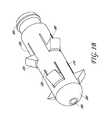
- FIG. 1Ashows a perspective view of one embodiment of a tissue anchoring device in an undeployed or compressed state.
- FIG. 1Bshows a perspective view of one embodiment of a tissue anchoring device in a deployed or expanded state.
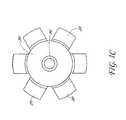
- FIG. 1Cshows a front view of one embodiment of a tissue anchoring device in the deployed or expanded state.
- FIG. 2Ashows a cross-sectional view of one embodiment of a tissue anchoring device in which the tissue anchoring device has partially deployed or expanded.
- FIG. 2Bshows a cross-sectional view of another embodiment of a tissue anchoring device in which the tissue anchoring device has partially deployed or expanded.
- FIG. 3Adepicts a perspective distal view of one embodiment of an anchor body in an undeployed or compressed state.
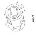
- FIG. 3Bdepicts a perspective proximal view of one embodiment of an anchor body in an undeployed or compressed state.
- FIG. 4Adepicts a perspective distal view of one embodiment of a spreader.
- FIG. 4Bdepicts a perspective proximal view of one embodiment of a spreader.
- FIG. 5Adepicts a side view of one embodiment of a tissue anchoring device attached to an inserter tool and covered by a sleeve.
- FIG. 5Bdepicts a perspective view of one embodiment of a tissue anchoring device attached to an inserter tool with the sleeve retracted.
- FIG. 6Ashows an exploded view of one embodiment of an inserter tool.
- FIG. 6Bshows a perspective view of one embodiment of an inner rod component of an insertion tool.
- FIG. 6Cshows a perspective view of one embodiment of an outer tube component of an insertion tool.
- FIG. 6Dshows a side view of one embodiment of a handle component of an insertion tool.
- FIG. 6Eshows a perspective view of one embodiment of a handle component of an insertion tool.
- FIG. 6Fshows a perspective view of one embodiment of an actuator shaft component of an insertion tool.
- FIG. 6Gshows a perspective view of one embodiment of a deployment knob component of an insertion tool.
- FIGS. 7A-7Cdepicts three perspective views of one embodiment of a tissue anchoring device in three different stages of a manufacturing process.
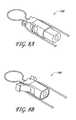
- FIG. 8Ashows a perspective view of one embodiment of a femoral tissue capture anchor device in an undeployed or unexpanded state.
- FIG. 8Bshows a perspective view of one embodiment of a femoral tissue capture anchor device in a deployed or expanded state.
- FIG. 9shows a perspective view of one embodiment of a tissue anchoring device comprising a tissue capture suture loop.
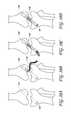
- FIGS. 10A-10Ddepicts four frontal views of the bones surrounding the human knee and one embodiment of a method of securing soft tissue to the bones using a tissue anchoring device.
- soft tissuemay be attached to bone utilizing one or more tissue anchoring devices, such a tissue anchoring device 100 depicted in FIG. 1A .
- the anchor body 200is comprised of a tubular wall 210 surrounding a central bore and compressible tabs 220 .
- the tubular wall 210is uniformly tubular in that it comprises a uniform diameter.
- the compressible tabsare configured to engage with soft tissue and bone, fixedly securing the anchor body 200 and the soft tissue in the bone.
- the compressible tabscomprise one or more teeth 230 which are configured to further engage with the tissue and bone.
- the number of compressible tabs 220 and teeth 230can vary.
- the compressible tabsare affixed to the tubular wall along an edge 240 .
- the edge 240is configured to allow pivotal movement about the tubular wall such that the compressible tabs are bendable between a compressed state and an expanded state.
- the tissue anchoring devicealso comprises a spreader 300 , which is insertable into the central bore at the anchor body's proximal end 250 and configured to urge the compressible tabs 220 radially outward relative to the tubular wall 210 upon insertion of the spreader into the central bore.
- the spreader 300is in its undeployed or uninserted state such that the compressible tabs 220 are collapsed into their compressible state.
- the tissue anchoring device 100is in a streamlined position such that there is little to no protrusion of the teeth 230 radially outward beyond the tubular wall.
- FIG. 1Bshows a perspective view in which the spreader 300 has been inserted into the central bore of the anchor body 200 , thus moving the compressible tabs 220 into their expanded state.
- the teeth 230extend radially outward from the anchor body 200 and are configured to engage with bone and fixedly secure the tissue anchoring device within the bone.
- the compressible tabsare positioned along circumferential rows.
- a first row 270contains compressible tabs located along a first axial position
- a second row 280contains compressible tabs located along a second axial position.
- the first row of tabs 270is offset circumferentially relative to the second row of tabs 280 such that no two compressible tabs 220 share the same longitudinal alignment. Such a configuration facilitates capture and fixation of a soft tissue by hindering slippage of the soft tissue between the compressible tabs.
- FIG. 1Cprovides a front view of the embodiment described in FIG. 1B .
- FIG. 1Cdepicts compressible tabs 220 in their expanded state and a first row of compressible tabs 270 offset circumferentially from a second row of compressible tabs 280 .
- the distal end 260 of the anchor bodyis substantially rounded to facilitate insertion of the anchor body into a bone tunnel and to slide around tendon positioned within the bone tunnel.
- a small hole 290may advantageously be provided in the center of the distal end 260 to facilitate engagement of the anchor body with an insertion tool, such insertion tool explained in subsequent paragraphs.
- the small hole 290may comprise threads to mate with the threads on the inner rod of the insertion tool.
- the tissue anchoring device 100is made entirely of a biocompatible engineering plastic.
- Other embodimentsinclude a tissue anchoring device made entirely, or in part, of a biocompatible non-metallic substance.
- Biocompatible engineering polymer materialssuch as polyether-ether-ketone, poly-ether-ketone, polyetherimide, ultrahigh molecular weight polyethylene, polyphenylene, poly(lactide-co-glycolide), polycaprolactone, or some other biocompatible polymer material known to those of skill in the art may be used.
- a non-metallic anchor systemmay provide certain advantages such as, for example, eliminating MRI artifacts.
- a plurality of compressible tabsare located along the same axial position, forming circumferential rows of compressible tabs.
- the compressible tabsmove about a hinge-like edge 240 , moving from a compressed state to an expanded state upon insertion of the spreader 300 through the proximal end 250 of the anchor body and into the central bore.
- the compressible tabs 220are substantially flush with the tubular wall and the teeth 230 protrude radially outwardly relative to the anchor body.
- FIG. 2Bdepicts a cross-sectional view of such an embodiment.
- each tabcan be configured to extend beyond the center line or central axis 255 of the central bore when the tab is in its compressed state.
- Such a configurationallows for the inclusion of larger teeth 230 on the compressible tab than would be possible with many other embodiments, thus facilitating increased contact between the teeth and bone.
- FIG. 3AOne embodiment, described in the preceding paragraph, is further illustrated in the perspective view provided in FIG. 3A .
- the anchor body 200is shown in isolation with the compressible tabs 220 found in their compressed or undeployed state.
- the anchor body 200is generally tubular or cylindrical in shape and is comprised of a uniform diameter.
- the compressible tabs 220bend inward along the bendable edge 240 such that the teeth 230 are largely retracted into the central bore inside the anchor body and do not extend substantially beyond the tubular wall 210 prior to insertion of the spreader.
- the compressible tabs 220are offset both axially and circumferentially relative to each other.
- FIG. 3BAnother embodiment of a compressed or undeployed anchor body is shown in the perspective view of FIG. 3B .
- the central bore defined by the tubular wall 210is visible from the proximal side of the anchor body.
- the anchor body of this embodimenthas an inner surface 215 of the tubular wall which is in contact with a spreader 300 when the spreader is inserted into the anchor body.
- the inner surface 215may be smooth.
- in inner surface 215 of the anchor body and the surface of the spreader 300may not be smooth, but rather, may be textured such as with a scallop shape or grooves so as to inhibit movement of spreader 300 once it is pushed into the anchor body.
- texturing in the inner surface 215is complementary to texturing in the outer surface of the spreader 300 .
- the inner surface 215has a circumferentially located groove 225 which engages with a circumferentially located ridge of a spreader upon insertion of the spreader to lock the spreader 300 into place when the anchor body is fully deployed.
- the grooved surface 225is oriented such that the distal end of the spreader 300 can be easily moved in the distal direction in the central bore with the ridge 315 snapping into the groove 225 as the proximal end of the inserter nears the proximal end of the anchor body.
- the groove 225can exist at different locations of the inner surface of the tubular wall 215 or along substantially the entire inner surface 215 .
- the anchor body 200may be coupled to the spreader 300 in several positions such that the spreader 300 need not be inserted into the anchor body 200 to its full extent in order to be secured to the anchor body 200 .
- a grooved surfaceis illustrated, it will be appreciated that other shapes are contemplated, including multiple concentric grooves, a series of protruding ridges, or any other suitable structure that permits a spreader 300 to be securely locked within the central bore of the anchor body 200 .
- the spreader 300may comprise any suitable shape configured to be inserted through the central bore of the anchor body 200 .
- the generally tapered distal end 340 of the spreaderis configured to come into contact with the compressible tabs of the anchor body and facilitate bending of the tabs into their expanded state upon insertion of the spreader into the anchor body.
- the body 310 of the spreaderis uniformly tubularly shaped and surrounds an axial bore configured for receiving an insertion tool.
- the tubular body 310 of the spreader 300comprises a circumferentially located ridge 325 near its proximal end 320 .
- the spreader 300is advanced into the anchor body 200 , spreading the compressible tabs 220 until the ridge 325 of the spreader 300 engages the groove 225 in the inner surface of the anchor body.
- the ridge 315may be undercut providing even more security against reversing.
- the proximal end of the spreadercomprises a generally flat face and a means for receiving the insertion tool.
- the proximal end 320 of the spreader 300comprises a hole 330 that receives the insertion tool.
- the spreaderAfter deployment, the spreader remains in the deployed anchor and the insertion tool's inner rod shears off from the anchor body such that the proximal end of the spreader 300 remains in the anchor in a state that is either flush or slightly recessed with respect to the proximal end of the anchor body 200 .
- the spreader 300will remain in the anchor body 200 with the compressible tabs 220 in their fully expanded position.
- the force provided by the interaction between the compressible tabs, teeth and bonekeeps the spreader 300 tightly engaged.
- Further protection against slipping or tilting of the spreader 300is provided by the optionally ridged sides of the spreader 300 .
- one or more of the compressible tabs 220have an indentation on a side facing the central bore. A ridge on the spreader 300 can then engage the indentation, thereby stabilizing the spreader 300 and preventing the spreader 300 from being advanced too far into the anchor.
- the spreader 300comprises an indentation that can engage with a protrusion on a side of a compressible tab facing the central bore.
- this featureIn addition to stabilizing the spreader 300 and preventing over-insertion, this feature also prevents rotation of the spreader 300 relative to the anchor. Inserting the spreader 300 into the anchor body 200 linearly, as opposed to twisting or screwing, is likely to be advantageous in that the linear motion will create no tendency to rotate the anchor. Thus, a linear approach is likely to prevent any twisting or turning of the captured soft tissue.
- the compressible tabsmay be of a thin enough material thickness such that they can be pushed in by a slidable sleeve 400 positioned over the anchor body 200 .
- the slidable sleeve 400is configured to hold the compressible tabs 200 in place substantially inside the anchor body 200 during insertion of the anchor body 200 into the bone tunnel.
- FIG. 5Ashows one embodiment of the anchor body 200 and slidable sleeve 400 combination with the anchor body 200 in its compressed state and with the combination connected to the outer tube 600 of the insertion tool.
- the slidable sleeve 400can be withdrawn when the anchor body 200 is in place inside a bone, and the compressible tabs will at least partially expand.
- FIG. 5Bdepicts one embodiment of the anchor body 200 and slidable sleeve combination with the slidable sleeve 400 in a retracted state such that the compressible tabs 220 of the anchor body 200 have partially expanded and the teeth 230 partially protrude radially outward from the tubular wall.
- the spreader 300is held adjacent to the anchor body 200 via the inserter tool 1000 prior to insertion of the inserter into the anchor body 200 .
- FIG. 6Adepicts individual components of an inserter tool.
- the inserter tool 1000comprises an inner rod or tube 500 , an outer tube 600 , a handle body 700 , a threaded actuator shaft 800 , and a deployment knob 900 .
- the inserter tool 1000is coupled to the tissue anchoring device 100 during manufacturing.
- the inserter toolis disposable.
- the inserter tool 1000is designed to insert and manipulate a tissue anchoring device, such the tissue anchoring device described above.
- the tissue anchoring deviceis manufactured to be attached to the inserter tool before packaging.
- the tissue anchoring deviceis coupled to the inserter tool shortly prior to insertion.
- the inserter toolis assembled as follows: the inserter tool 1000 is configured such that the inner rod 500 is disposed within the outer tube 600 .
- the outer tubeis configured to fit against the proximal end of the spreader 300 .
- the inner rod 500extends through outer tube 600 and is configured to attach to the distal end of the anchor body 200 via threading on both the distal hole in the anchor body 200 and threading on the distal end of the inner rod 500 .
- the proximal end of the outer tube 600is connected to a handle 700 and the inner rod 500 extends through the proximal end of the outer tube 600 and screws into the threaded actuator shaft 800 .
- the actuator shaft 800extends just past the proximal end of the handle 700 where it is configured to secure with a deployment knob 900 .
- FIG. 6Bshows a perspective view of an embodiment of the inner rod 500 .
- the inner rodis an inner tube.
- the inner rodcomprises a rod-like or tube-like body 525 , a distal end 510 configured to secure to the spreader 300 , and a proximal end 520 which is configured to interact with the other components of the inserter such as the actuator shaft 800 .
- the inner rod 500is configured such that a proximal end 520 is advanced through the outer tube 600 and into the handle 700 where it is further secured within the actuator shaft 800 via threading.
- the distal end of the inner rod 500is configured to extend through the central bore in the spreader 300 and the anchor body 200 and then be secured to the distal end of the anchor body 200 .
- the inner rodis retracted until the tissue anchoring device is fully deployed and the inner rod is separated from the anchor.
- the inner rod 500extends through the central bore in the spreader 300 and the anchor body 200 before coupling with the distal end of the anchor body 200 .
- the inner rod 500couples with the anchor body 200 through threads 505 on the end of the inner rod 500 and within the distal end of the anchor body 200 .
- the inner rod 500may couple to the anchor body 200 through other securing mechanisms such as adhesives, welding or frictional fit.
- FIG. 6Cshows an embodiment of the outer tube 600 .
- the outer tube 600is attached at its proximal end 605 to the distal end of handle 700 via threading 625 .
- the distal end 610 of the outer tube 600is configured such that the inner rod 500 can be drawn into the outer tube 600 through the distal end 610 of outer tube 600 .
- the distal surface of the outer tube 600may be level with the proximal surface of the anchor body 200 .
- the inner rod 500withdraws further into the outer tube upon the continued rotation of the deployment knob and advancement of the actuator shaft, the inner rod 500 strips the threading from the anchor body 200 and the inserter tool 400 detaches from the anchor.
- FIGS. 6D and 6Eshow embodiments of a handle body 700 .
- FIG. 6Dis a cross-sectional view of one embodiment of a handle 700 and 6 E is a cut-away view of the handle body 700 .
- the proximal end of the handle 700is configured to receive the deployment knob 900 via the ridges 730 which hold the knob 900 secure.
- the actuator shaft 800is housed within the handle body 700 .
- a set of brackets or braces 710 each having a flat surface 715secure the actuator shaft 800 within the handle 700 .
- the distal end 770 of the handleis configured to receive the outer tube 600 via threads 725 in opening 740 .
- the outer tube 600is permanently affixed to the handle 700 at its distal end.
- FIG. 6Fdepicts the threaded actuator shaft 800 .
- the actuator shaft 800is comprised of a distal end 805 comprising a threaded hole 810 which is configured to receive the inner rod 500 , a second threaded portion 825 on the body of the shaft configured to advance the inner rod 500 , and a proximal end 820 configured to secure within the deployment knob 900 .
- the threading 825 of the actuator 800has two flat areas 830 , one on each side, where there is no threading. These flat areas 830 fit within the flat brackets 710 of the handle such that the actuator 800 cannot rotate within the handle.
- the body of the actuator shaft 800is configured with threading 825 to permit the shaft 800 to advance the inner tube 500 .
- the body of the actuator shaft 800is not perfectly round, but rather is oval shaped with flat sides 830 that fit into the handle body 700 in such a way that the actuator shaft 800 cannot itself rotate when the deployment knob 900 is turned and the shaft 800 advances via knob 900 .
- the threadsdo not go all the way around the shaft but rather flatten out on the flattened sides of the shaft.
- the actuator shaftis configured as a coaxial system. That is, the spreader 300 , inner tube 500 and actuator 800 are configured to operate as one piece.
- the flat brackets 710 in the handlemake the actuator shaft 800 stay on plane such that the actuator shaft 800 itself cannot rotate within the handle 700 .
- the proximal end of the inner tube 500couples with the distal end of the actuator shaft 800 via threading.
- FIG. 6Gdepicts a deployment knob 900 .
- the deployment knob 900comprises a central hole 910 which is configured with threading 905 , and a groove 930 configured to be received by a corresponding ridge 730 of the handle 700 .
- the threading 905 in the central hole 910is configured to receive the actuator shaft 800 .
- the deployment knob 900is configured to advance, relative to the deployment knob 900 , the inner rod 500 via the actuator shaft 800 .
- the actuator shaft 800is joined at its proximal end to the distal end of the deployment knob 900 via threading 905 in the central hole 910 .
- the actuator shaft 800is attached to the inner rod 500 by way of the proximal end of the inner rod 500 advancing into the distal end of the actuator shaft via threading so that when the deployment knob 900 is rotated, the mechanism of the shaft 800 advances the inner rod 500 proximally such that the spreader 300 is then advanced into the anchor body 200 to expand the anchor body 200 into bone and secure the tissue anchoring device.
- the deployment knob 900is threaded 905 to receive the actuator shaft via the groove 930 of knob 900 fitting with the proximal end ridge 730 of the handle body 700 .
- the actuator shaft 800is advanced in a proximal direction until the anchor body 200 is deployed and locked into place.
- the inner rod 500When in the position for deployment, the inner rod 500 is positioned within the outer tube 600 , and the outer tube is flush with the anchor body 200 .
- the inner rod 500may hold the anchor body 200 steady during insertion and deployment.
- the inner rod 500extends through the spreader 300 and couples to the anchor body 200 via threading.
- the spreader 300is configured to be advanced distally through the proximal end of the anchor body 200 by the retraction of the inner rod 500 via rotating the deployment knob 900 , which pulls the anchor body 200 proximally relative to the spreader 300 .
- the outer tube 600provides the mechanism to push the spreader 300 into the central hole 225 in the anchor body 200 to fully expand the anchor body 200 .
- the inner rod 500is continually retracted via a screwing motion until the spreader 300 locks into the anchor body 200 .
- the deployment knob 900continues to turn and the inner rod 500 continues to pull on the threads of the anchor body 200
- the inner rod 500strips the threads from the inside of the anchor body 200 and the insertion tool 400 releases from the anchor body 200 . Any thread shavings are contained within the outer tube 600 .
- a pre-attached delivery handleis provided.
- the insertion tool or delivery handleis disposable. In other embodiments, the insertion tool can be sterilized, reloaded, and reused.
- the anchor body 200 comprising compressible tabs 220is manufactured as depicted in FIGS. 7A-7C .
- the tubular wall 210 with central boreis manufactured using traditional machining techniques.
- PEEK rod stockmay be machined to form the anchor body depicted in FIG. 7A .
- a series of ridges 235 surrounding the tubular wall 210are produced with machining.
- the ridges 235serve as precursors to the teeth 230 on compressible tabs 220 .
- the teeth 230are produced as depicted in FIG. 7B by machining away portions of the ridges 235 .
- slots 245are cut into the tubular wall 210 to form the three sides of the compressible tabs 220 .
- the slots 245may be formed using any suitable technique, for example, laser etching.
- manufacturingmay be complete after forming the tabs 220 as depicted in FIG. 7C .
- the tubular wall 210can be heated and the compressible tabs 220 compressed into central bore, such as by using a sleeve slid over the anchor body 200 . Upon cooling, the tabs 220 will maintain their compressed position until a spreader is inserted into the central bore to deploy the tabs 220 .
- the anchors described abovemay be used to secure a tissue graft in an ACL repair.
- the anchors described aboveare used to anchor tissue in a bone tunnel in the tibia.
- the tissue graftis first anchored within a bone tunnel in the femur.
- Any suitable anchormay be used to secure tissue to the femur.
- suitable anchorsinclude a tissue grasping feature that can be used to capture tissue and feed it through bone tunnels in the tibia and/or femur.
- the tissue grasping featureincludes a suture loop that can be tightened around one or more strands of tissue.
- FIGS. 8A and 8Bdepict a suture loop anchor 1100 in FIGS. 8A and 8B and described in more detail in FIGS. 13A-16B in U.S. Patent Application Publication No. 2011-0112550, which is incorporated herein by reference in its entirety.
- FIG. 8Adepicts the femoral anchor 1100 in an undeployed state with suture loop ready to capture tissue. After tissue capture and insertion in the femur, lateral protrusions on the anchor 1100 may be deployed to secure the anchor and issue into the femur.
- FIG. 8Bdepicts the femoral anchor 1100 in its deployed state.
- a modified version of the tibial anchor described abovemay be used as the femoral anchor.
- the anchor body 1102instead of a rounded distal end, the anchor body 1102 comprises a flat, depressed, or saddle shaped distal end 1106 . Two apertures or provided in the distal end 1106 to accommodate the treading of a suture to foam a suture loop 1104 in the distal end.
- tissuemay be captured within the suture loop 1104 , the suture tightened, and then the anchor 1102 with captured tissue inserted into the femoral bone tunnel.
- the anchor 1102may be deployed using the same spreader and inserter as described above for the tibial anchor.
- FIGS. 10A-10Ddepict some non-limiting suitable ACL repair techniques utilizing the anchors described herein.
- bone tunnels 1110 and 1120are formed in the tibia and femur.
- both tunnels 1110 and 1120are formed using a single drill drilling through the tibia and then into the femur.
- the femoral tunnel 1110 and tibial tunnel 1120may be formed separately.
- a surgeonobtains a suitable tissue graft 1130 , which may include tendon from the patient (e.g., one or more patellar or hamstring tendons), from a cadaver, or a synthetic graft.
- the tissue graft 1130is then captured by a femoral anchor 1100 , such as the anchors described in FIGS. 8A-9 .
- the femoral anchor 1100is then inserted into the femoral tunnel 1110 and deployed to secure the graft 1130 into the femur.
- a lateral techniqueis used whereby the surgeon inserts the femoral anchor 1100 with captured tissue graft 1130 laterally into the space between the femur and tibia.
- the femoral anchor 1100is then inserted directly into the femoral bone tunnel 1110 .
- the jointmay be abducted to facilitate direct insertion in the femoral tunnel 1110 .
- the tissue graft 1130may then be fed down through the tibal bone tunnel 1120 and out the other side resulting in the configuration depicted in FIG. 10C .
- a suture loopis fed up through the tibial tunnel 1120 , the graft 1130 is fed through the loop, and then the loop is pulled back through the tibial tunnel 1120 , drawing the graft 1130 with it.
- an in-line approachmay be used where the femoral anchor 1100 with captured tissue graft 1130 is inserted through the tibial bone tunnel 1120 and then into the femoral bone tunnel 1110 .
- the resultis graft running from the femoral anchor 1100 through and out of the tibial tunnel 1120 as depicted in FIG. 10C .
- the jointmay be position and the tissue graft 1130 tensioned as appropriate.
- a tibial anchor 100 as described hereinmay be inserted into the opening of the tibial bone tunnel 1120 and deployed to secure the graft 1130 to the tibia. Excess graft 1130 may then be trimmed to be flush with the tibial anchor 100 .
- the approach described aboveis conducted using a single strand of tissue graft 1130 .
- the graft 1130may be captured by the femoral anchor 1100 and doubled over the end of the anchor anchor such that two parallel portions of the graft 1130 run from the femoral anchor 1100 to the tibial anchor 100 .
- two strands of tissue graft 1130may be doubled over the end of the femoral anchor 1100 resulting in four parallel portions of graft 1130 running from the femoral anchor 1100 to the tibial anchor 100 .
- ACL repair techniqueshave been described herein, it will be appreciated that the anchors described may be used in any number of procedures where a surgeon desires to fix soft tissue to bone.
Landscapes
- Health & Medical Sciences (AREA)
- Life Sciences & Earth Sciences (AREA)
- Veterinary Medicine (AREA)
- Public Health (AREA)
- Rheumatology (AREA)
- General Health & Medical Sciences (AREA)
- Animal Behavior & Ethology (AREA)
- Engineering & Computer Science (AREA)
- Biomedical Technology (AREA)
- Heart & Thoracic Surgery (AREA)
- Oral & Maxillofacial Surgery (AREA)
- Vascular Medicine (AREA)
- Transplantation (AREA)
- Cardiology (AREA)
- Rehabilitation Therapy (AREA)
- Orthopedic Medicine & Surgery (AREA)
- Surgery (AREA)
- Nuclear Medicine, Radiotherapy & Molecular Imaging (AREA)
- Medical Informatics (AREA)
- Molecular Biology (AREA)
- Surgical Instruments (AREA)
Abstract
Description
Claims (14)
Priority Applications (3)
| Application Number | Priority Date | Filing Date | Title |
|---|---|---|---|
| US13/269,460US9044313B2 (en) | 2010-10-08 | 2011-10-07 | System and method for securing tissue to bone |
| US14/727,410US10080647B2 (en) | 2010-10-08 | 2015-06-01 | System and method for securing tissue to bone |
| US16/105,478US10959831B2 (en) | 2010-10-08 | 2018-08-20 | System and method for securing tissue to bone |
Applications Claiming Priority (2)
| Application Number | Priority Date | Filing Date | Title |
|---|---|---|---|
| US39155410P | 2010-10-08 | 2010-10-08 | |
| US13/269,460US9044313B2 (en) | 2010-10-08 | 2011-10-07 | System and method for securing tissue to bone |
Related Child Applications (1)
| Application Number | Title | Priority Date | Filing Date |
|---|---|---|---|
| US14/727,410DivisionUS10080647B2 (en) | 2010-10-08 | 2015-06-01 | System and method for securing tissue to bone |
Publications (2)
| Publication Number | Publication Date |
|---|---|
| US20120203339A1 US20120203339A1 (en) | 2012-08-09 |
| US9044313B2true US9044313B2 (en) | 2015-06-02 |
Family
ID=46601191
Family Applications (3)
| Application Number | Title | Priority Date | Filing Date |
|---|---|---|---|
| US13/269,460Active2031-11-28US9044313B2 (en) | 2010-10-08 | 2011-10-07 | System and method for securing tissue to bone |
| US14/727,410ActiveUS10080647B2 (en) | 2010-10-08 | 2015-06-01 | System and method for securing tissue to bone |
| US16/105,478Active2032-04-09US10959831B2 (en) | 2010-10-08 | 2018-08-20 | System and method for securing tissue to bone |
Family Applications After (2)
| Application Number | Title | Priority Date | Filing Date |
|---|---|---|---|
| US14/727,410ActiveUS10080647B2 (en) | 2010-10-08 | 2015-06-01 | System and method for securing tissue to bone |
| US16/105,478Active2032-04-09US10959831B2 (en) | 2010-10-08 | 2018-08-20 | System and method for securing tissue to bone |
Country Status (1)
| Country | Link |
|---|---|
| US (3) | US9044313B2 (en) |
Cited By (16)
| Publication number | Priority date | Publication date | Assignee | Title |
|---|---|---|---|---|
| US20140094921A1 (en)* | 2012-10-02 | 2014-04-03 | Titan Spine, Llc | Implants with self-deploying anchors |
| US20150012050A1 (en)* | 2013-07-03 | 2015-01-08 | Biomet Manufacturing, Llc | Bone fusion device |
| US20150028079A1 (en)* | 2007-03-07 | 2015-01-29 | Covidien Ag | Stapler for mucosectomy |
| US9706984B2 (en) | 2009-01-30 | 2017-07-18 | Conmed Corporation | System and method for attaching soft tissue to bone |
| US9775597B2 (en) | 2011-10-04 | 2017-10-03 | Conmed Corporation | Dual expansion anchor |
| US9826970B2 (en) | 2009-10-13 | 2017-11-28 | Conmed Corporation | System and method for securing tissue to bone |
| US9925036B2 (en) | 2013-03-15 | 2018-03-27 | Conmed Corporation | System and method for securing tissue to bone |
| US9968349B2 (en) | 2011-04-13 | 2018-05-15 | Conmed Corporation | System and method for securing tissue to bone |
| US10080647B2 (en) | 2010-10-08 | 2018-09-25 | Conmed Corporation | System and method for securing tissue to bone |
| US10149751B2 (en) | 2013-03-14 | 2018-12-11 | Conmed Corporation | Tissue capturing bone anchor |
| US20190002164A1 (en)* | 2015-08-07 | 2019-01-03 | Pacplus Co., Ltd. | Stopper |
| US10624734B2 (en) | 2016-10-18 | 2020-04-21 | Arthrex, Inc. | Surgical assembly for tissue repair |
| US20210177609A1 (en)* | 2019-12-13 | 2021-06-17 | Colorado State University Research Foundation | Anchoring device |
| US11160546B2 (en) | 2019-07-11 | 2021-11-02 | Arthrex, Inc. | Expanding implant and method of tissue fixation |
| US20230277230A1 (en)* | 2022-03-01 | 2023-09-07 | Orthopedic Designs North America, Inc. | Graft fixation screw with tangs |
| US11980358B2 (en) | 2019-01-16 | 2024-05-14 | Lsi Solutions, Inc. | Mechanical suture fastener |
Families Citing this family (6)
| Publication number | Priority date | Publication date | Assignee | Title |
|---|---|---|---|---|
| CN103784172B (en)* | 2014-03-04 | 2017-03-08 | 叶维光 | Ligament reconstructive system |
| US10828146B2 (en) | 2016-08-04 | 2020-11-10 | Stryker Corporation | Instrumentation for soft tissue reconstruction |
| JP6998973B2 (en)* | 2017-06-12 | 2022-01-18 | コンメッド コーポレーション | Expansion anchor |
| US11207172B2 (en)* | 2019-01-08 | 2021-12-28 | Covidien Lp | Stent designs to cover catheter access site |
| US11992218B2 (en)* | 2021-10-18 | 2024-05-28 | Cilag Gmbh International | Metal injection molded anvil for circular surgical stapler |
| CN113995456A (en)* | 2021-12-30 | 2022-02-01 | 杭州锐健马斯汀医疗器材有限公司 | Meniscus fixing device and meniscus fixing method |
Citations (149)
| Publication number | Priority date | Publication date | Assignee | Title |
|---|---|---|---|---|
| US4590928A (en) | 1980-09-25 | 1986-05-27 | South African Invention Development Corporation | Surgical implant |
| EP0241240A2 (en) | 1986-04-07 | 1987-10-14 | E. Marlowe Goble | Suture anchor apparatus |
| EP0270704A1 (en) | 1986-12-12 | 1988-06-15 | Aesculap Ag | Anchoring element for fastening an osteosynthesis plate to a bone |
| US4870957A (en) | 1988-12-27 | 1989-10-03 | Marlowe Goble E | Ligament anchor system |
| US4960420A (en) | 1988-08-23 | 1990-10-02 | Marlowe Goble E | Channel ligament clamp and system |
| US4988351A (en) | 1989-01-06 | 1991-01-29 | Concept, Inc. | Washer for use with cancellous screw for attaching soft tissue to bone |
| US5037422A (en) | 1990-07-02 | 1991-08-06 | Acufex Microsurgical, Inc. | Bone anchor and method of anchoring a suture to a bone |
| FR2671717A1 (en) | 1991-01-17 | 1992-07-24 | Asa Laboratoires Prothaid | Expansion bolt for the fixation of a ligament prosthesis on the cortical wall of a bone |
| US5161916A (en) | 1991-06-03 | 1992-11-10 | White Claude C | Self-seating expansion anchor |
| US5167665A (en) | 1991-12-31 | 1992-12-01 | Mckinney William W | Method of attaching objects to bone |
| US5176682A (en) | 1992-06-01 | 1993-01-05 | Chow James C Y | Surgical implement |
| US5192303A (en) | 1987-05-18 | 1993-03-09 | Mitek Surgical Products, Inc. | Suture anchor |
| US5197983A (en) | 1988-04-19 | 1993-03-30 | W. L. Gore & Associates, Inc. | Ligament and tendon prosthesis |
| US5209756A (en) | 1989-11-03 | 1993-05-11 | Bahaa Botros Seedhom | Ligament fixation staple |
| US5222963A (en) | 1991-01-17 | 1993-06-29 | Ethicon, Inc. | Pull-through circular anastomosic intraluminal stapler with absorbable fastener means |
| US5224946A (en) | 1990-07-02 | 1993-07-06 | American Cyanamid Company | Bone anchor and method of anchoring a suture to a bone |
| US5246443A (en) | 1990-10-30 | 1993-09-21 | Christian Mai | Clip and osteosynthesis plate with dynamic compression and self-retention |
| US5268001A (en) | 1990-09-25 | 1993-12-07 | Innovasive Devices, Inc. | Bone fastener |
| EP0574707A1 (en) | 1992-06-15 | 1993-12-22 | United States Surgical Corporation | Suture anchoring device and method |
| US5326205A (en) | 1992-05-27 | 1994-07-05 | Anspach Jr William E | Expandable rivet assembly |
| US5336240A (en) | 1991-03-04 | 1994-08-09 | Liebscherkunststofftechnik | Bone-dowel assembly for anchoring a suture |
| EP0409364B1 (en) | 1989-07-13 | 1994-09-28 | ARTOS Medizinische Produkte GmbH | Junction element for osteosynthesis |
| US5354298A (en) | 1991-03-22 | 1994-10-11 | United States Surgical Corporation | Suture anchor installation system |
| US5372599A (en) | 1993-03-12 | 1994-12-13 | Mitek Surgical Products, Inc. | Surgical anchor and method for deploying the same |
| US5380334A (en) | 1993-02-17 | 1995-01-10 | Smith & Nephew Dyonics, Inc. | Soft tissue anchors and systems for implantation |
| US5397356A (en) | 1993-01-15 | 1995-03-14 | Depuy Inc. | Pin for securing a replacement ligament to a bone |
| US5417691A (en) | 1982-05-20 | 1995-05-23 | Hayhurst; John O. | Apparatus and method for manipulating and anchoring tissue |
| US5417712A (en) | 1994-02-17 | 1995-05-23 | Mitek Surgical Products, Inc. | Bone anchor |
| WO1995015726A1 (en) | 1993-12-06 | 1995-06-15 | Innovasive Devices, Inc. | Bone fastener |
| EP0673624A2 (en) | 1994-03-24 | 1995-09-27 | Ethicon, Inc. | Two-piece suture anchor with barbs |
| US5472452A (en) | 1994-08-30 | 1995-12-05 | Linvatec Corporation | Rectilinear anchor for soft tissue fixation |
| US5480403A (en) | 1991-03-22 | 1996-01-02 | United States Surgical Corporation | Suture anchoring device and method |
| EP0504915B1 (en) | 1991-03-22 | 1996-01-31 | United States Surgical Corporation | Orthopaedic fastener |
| US5500001A (en) | 1993-06-18 | 1996-03-19 | Linvatec Corporation | Suture anchor for soft tissue fixation |
| US5501695A (en) | 1992-05-27 | 1996-03-26 | The Anspach Effort, Inc. | Fastener for attaching objects to bones |
| US5505735A (en) | 1993-06-10 | 1996-04-09 | Mitek Surgical Products, Inc. | Surgical anchor and method for using the same |
| US5522844A (en) | 1993-06-22 | 1996-06-04 | Johnson; Lanny L. | Suture anchor, suture anchor installation device and method for attaching a suture to a bone |
| US5522846A (en) | 1993-05-14 | 1996-06-04 | Bonutti; Peter M. | Suture anchor |
| US5522845A (en) | 1994-09-27 | 1996-06-04 | Mitek Surgical Products, Inc. | Bone anchor and bone anchor installation |
| US5545180A (en) | 1993-12-13 | 1996-08-13 | Ethicon, Inc. | Umbrella-shaped suture anchor device with actuating ring member |
| US5569306A (en) | 1995-06-06 | 1996-10-29 | Thal; Raymond | Knotless suture anchor assembly |
| US5601557A (en) | 1982-05-20 | 1997-02-11 | Hayhurst; John O. | Anchoring and manipulating tissue |
| WO1997007741A1 (en) | 1995-08-24 | 1997-03-06 | Inbae Yoon | Suture tie device system and method for suturing anatomical tissue proximate an opening |
| US5618314A (en) | 1993-12-13 | 1997-04-08 | Harwin; Steven F. | Suture anchor device |
| US5628751A (en) | 1993-06-21 | 1997-05-13 | United States Surgical Corporation | Orthopedic fastener applicator with rotational or longitudinal driver |
| US5632748A (en) | 1993-06-14 | 1997-05-27 | Linvatec Corporation | Endosteal anchoring device for urging a ligament against a bone surface |
| US5643321A (en) | 1994-11-10 | 1997-07-01 | Innovasive Devices | Suture anchor assembly and methods |
| US5645589A (en) | 1994-08-22 | 1997-07-08 | Li Medical Technologies, Inc. | Anchor and method for securement into a bore |
| US5649963A (en) | 1994-11-10 | 1997-07-22 | Innovasive Devices, Inc. | Suture anchor assembly and methods |
| US5702215A (en) | 1995-06-05 | 1997-12-30 | Li Medical Technologies, Inc. | Retractable fixation device |
| US5707395A (en) | 1997-01-16 | 1998-01-13 | Li Medical Technologies, Inc. | Surgical fastener and method and apparatus for ligament repair |
| US5718717A (en) | 1996-08-19 | 1998-02-17 | Bonutti; Peter M. | Suture anchor |
| US5720753A (en) | 1991-03-22 | 1998-02-24 | United States Surgical Corporation | Orthopedic fastener |
| US5733306A (en) | 1993-05-14 | 1998-03-31 | Bonutti; Peter M. | Method and apparatus for anchoring a suture |
| US5741282A (en) | 1996-01-22 | 1998-04-21 | The Anspach Effort, Inc. | Soft tissue fastener device |
| US5749899A (en) | 1994-03-30 | 1998-05-12 | T Deux C | Intraosseous anchoring method and device |
| US5782865A (en) | 1995-08-25 | 1998-07-21 | Grotz; Robert Thomas | Stabilizer for human joints |
| US5814072A (en) | 1996-11-15 | 1998-09-29 | Bonutti; Peter M. | Method and apparatus for use in anchoring a suture |
| US5814071A (en) | 1994-11-10 | 1998-09-29 | Innovasive Devices, Inc. | Suture anchor assembly and methods |
| US5849004A (en) | 1996-07-17 | 1998-12-15 | Bramlet; Dale G. | Surgical anchor |
| US5891168A (en) | 1997-01-31 | 1999-04-06 | Thal; Raymond | Process for attaching tissue to bone using a captured-loop knotless suture anchor assembly |
| USRE36289E (en) | 1993-12-13 | 1999-08-31 | Ethicon, Inc. | Umbrella shaped suture anchor device with actuating ring member |
| US5948000A (en) | 1996-10-03 | 1999-09-07 | United States Surgical Corporation | System for suture anchor placement |
| US5948002A (en) | 1996-11-15 | 1999-09-07 | Bonutti; Peter M. | Apparatus and method for use in positioning a suture anchor |
| US5957953A (en) | 1996-02-16 | 1999-09-28 | Smith & Nephew, Inc. | Expandable suture anchor |
| US5964764A (en) | 1998-03-24 | 1999-10-12 | Hugh S. West, Jr. | Apparatus and methods for mounting a ligament graft to a bone |
| US5980558A (en) | 1997-09-30 | 1999-11-09 | Biomet Inc. | Suture anchor system |
| US6007566A (en) | 1997-03-25 | 1999-12-28 | Mitek Surgical Products, Inc. | System for anchoring tissue to bone |
| US6022373A (en) | 1996-09-10 | 2000-02-08 | Li Medical Technologies, Inc. | Surgical anchor and package and cartridge for surgical anchor |
| US6024758A (en) | 1998-02-23 | 2000-02-15 | Thal; Raymond | Two-part captured-loop knotless suture anchor assembly |
| US6063037A (en) | 1998-08-21 | 2000-05-16 | Manan Medical Products, Inc. | Bone marrow biopsy needle |
| US6086591A (en) | 1999-01-29 | 2000-07-11 | Smith & Nephew, Inc. | Soft tissue anchor |
| US6146406A (en) | 1998-02-12 | 2000-11-14 | Smith & Nephew, Inc. | Bone anchor |
| US6149669A (en) | 1997-10-30 | 2000-11-21 | Li Medical Technologies, Inc. | Surgical fastener assembly method of use |
| US6203565B1 (en) | 1990-06-28 | 2001-03-20 | Peter M. Bonutti | Surgical devices assembled using heat bondable materials |
| US6241732B1 (en) | 1998-11-03 | 2001-06-05 | David W. Overaker | Biocompatible absorbable rivets and pins for use in surgical procedures |
| US6287324B1 (en) | 2000-01-28 | 2001-09-11 | Shoulderon Ltd. | Self-drilling surgical suture anchor |
| US20010041916A1 (en) | 2000-05-03 | 2001-11-15 | Bonutti Peter M. | Method of securing body tissue |
| US6319269B1 (en) | 1995-04-21 | 2001-11-20 | Lehmann K. Li | Fixation device and method for installing same |
| US6328758B1 (en) | 1998-04-21 | 2001-12-11 | Tornier Sa | Suture anchor with reversible expansion |
| WO2002032345A2 (en) | 2000-10-17 | 2002-04-25 | Coapt Systems, Inc. | Intraosseous soft tissue-to-bone anchor |
| US6464713B2 (en) | 1990-06-28 | 2002-10-15 | Peter M. Bonutti | Body tissue fastening |
| US20030004545A1 (en) | 2001-05-25 | 2003-01-02 | Burkhart Stephen S. | Interference fit knotless suture anchor fixation |
| USRE37963E1 (en) | 1995-06-06 | 2003-01-07 | Raymond Thal | Knotless suture anchor assembly |
| US6540770B1 (en) | 1998-04-21 | 2003-04-01 | Tornier Sa | Reversible fixation device for securing an implant in bone |
| US6544281B2 (en) | 2000-06-22 | 2003-04-08 | Arthrex, Inc. | Graft fixation using a screw or plug against suture or tissue |
| US6547800B2 (en) | 2001-06-06 | 2003-04-15 | Opus Medical, Inc. | Method and apparatus for attaching connective tissues to bone using a cortical bone anchoring device |
| US6554862B2 (en) | 1996-11-27 | 2003-04-29 | Ethicon, Inc. | Graft ligament anchor and method for attaching a graft ligament to a bone |
| US6562071B2 (en) | 2000-06-14 | 2003-05-13 | Jaervinen Teppo | Fixation anchor |
| US20030100903A1 (en) | 2000-08-21 | 2003-05-29 | Cooper Daniel E. | Soft tissue fixation device |
| US6582453B1 (en) | 2000-07-14 | 2003-06-24 | Opus Medical, Inc. | Method and apparatus for attaching connective tissues to bone using a suture anchoring device |
| US6585730B1 (en) | 2000-08-30 | 2003-07-01 | Opus Medical, Inc. | Method and apparatus for attaching connective tissues to bone using a knotless suture anchoring device |
| US20030130695A1 (en) | 1999-08-10 | 2003-07-10 | Mcdevitt Dennis | Self-locking suture anchor |
| US6616694B1 (en) | 1996-11-21 | 2003-09-09 | Ethicon, Inc. | Apparatus for anchoring autologous or artificial tendon grafts in bone |
| US6632224B2 (en) | 1996-11-12 | 2003-10-14 | Triage Medical, Inc. | Bone fixation system |
| US6648890B2 (en) | 1996-11-12 | 2003-11-18 | Triage Medical, Inc. | Bone fixation system with radially extendable anchor |
| US6652561B1 (en) | 2000-10-13 | 2003-11-25 | Opus Medical, Inc | Method and apparatus for attaching connective tissues to bone using a perforated suture anchoring device |
| US6656183B2 (en) | 2001-11-08 | 2003-12-02 | Smith & Nephew, Inc. | Tissue repair system |
| US6660022B1 (en) | 1999-06-01 | 2003-12-09 | Smith & Nephew, Inc. | Rotor blade anchor and tool for installing same |
| WO2003105700A1 (en) | 2002-06-12 | 2003-12-24 | Blue Planet Medical, Ltd. | Device and method for attaching soft tissue to bone |
| US6673094B1 (en) | 2000-02-23 | 2004-01-06 | Ethicon, Inc. | System and method for attaching soft tissue to bone |
| US20040010287A1 (en) | 1999-08-09 | 2004-01-15 | Bonutti Peter M. | Method and apparatus for securing tissue |
| US6689135B2 (en) | 2002-01-25 | 2004-02-10 | Albert Enayati | Expandable bone fastener and installation tool |
| US6692516B2 (en) | 2000-11-28 | 2004-02-17 | Linvatec Corporation | Knotless suture anchor and method for knotlessly securing tissue |
| US20040093031A1 (en) | 2000-06-22 | 2004-05-13 | Burkhart Stephen S. | Graft fixation using a plug against suture |
| US20040138683A1 (en) | 2003-01-09 | 2004-07-15 | Walter Shelton | Suture arrow device and method of using |
| US6770076B2 (en) | 2001-02-12 | 2004-08-03 | Opus Medical, Inc. | Method and apparatus for attaching connective tissues to bone using a knotless suture anchoring device |
| US20040230194A1 (en) | 2002-06-12 | 2004-11-18 | Urbanski Mark G. | Device and method for attaching soft tissue to bone |
| US6840953B2 (en) | 2000-12-22 | 2005-01-11 | United States Surgical Corporation | Suture screw |
| US6846313B1 (en) | 1998-11-03 | 2005-01-25 | Codman & Shurtleff, Inc. | One-piece biocompatible absorbable rivet and pin for use in surgical procedures |
| US20050055027A1 (en) | 2002-02-25 | 2005-03-10 | Yeung Jeffrey Eric | Expandable fastener with compressive grips |
| US6887271B2 (en) | 2001-09-28 | 2005-05-03 | Ethicon, Inc. | Expanding ligament graft fixation system and method |
| US6932834B2 (en) | 2002-06-27 | 2005-08-23 | Ethicon, Inc. | Suture anchor |
| US7037324B2 (en) | 2000-09-15 | 2006-05-02 | United States Surgical Corporation | Knotless tissue anchor |
| US20060106422A1 (en) | 2004-11-16 | 2006-05-18 | Del Rio Eddy W | Anchor/suture used for medical procedures |
| WO2006055823A3 (en) | 2004-11-18 | 2006-09-08 | Cayenne Medical Inc | Devices, systems and methods for material fixation |
| US20060229617A1 (en)* | 2005-02-25 | 2006-10-12 | Orthomechanics Ltd. | Intramedullary devices and methods of deploying the same |
| US20060235402A1 (en) | 2005-03-11 | 2006-10-19 | Orthofix International B.V. | Device for the ostheosynthesis of proximal humerus fractures |
| US20060264950A1 (en) | 2005-05-18 | 2006-11-23 | Nelson Charles L | Minimally Invasive Actuable Bone Fixation Devices |
| US20060265064A1 (en) | 2001-10-01 | 2006-11-23 | Paul Re | Apparatus and method for reconstructing a ligament |
| US7144413B2 (en) | 2001-04-20 | 2006-12-05 | Synthes (U.S.A.) | Graft fixation system and method |
| US20060282081A1 (en) | 2004-04-16 | 2006-12-14 | Fanton Gary S | Apparatus and method for securing tissue to bone with a suture |
| US20070027477A1 (en) | 2003-08-11 | 2007-02-01 | Chudik Steven C | Suture pin device |
| US7226469B2 (en) | 1999-02-02 | 2007-06-05 | Arthrex, Inc. | Insert molded suture anchor |
| US20070142835A1 (en) | 2004-06-02 | 2007-06-21 | Green Michael L | Suture anchor |
| US20070198018A1 (en)* | 2006-02-23 | 2007-08-23 | Lutz Biedermann | Bone anchoring device |
| US7309355B2 (en) | 2003-06-27 | 2007-12-18 | Depuy Mitek, Inc. | Flexible tibial sheath |
| US20080033445A1 (en) | 1997-01-02 | 2008-02-07 | Zucherman James F | Spine distraction implant and method |
| US20080051795A1 (en) | 2003-05-27 | 2008-02-28 | Depuy Mitek, Inc. | Tissue fixation device |
| US7381213B2 (en) | 2000-10-18 | 2008-06-03 | Depuy Mitek, Inc. | Knotless bioabsorbable suture anchor system and method |
| US20080183220A1 (en) | 2007-01-19 | 2008-07-31 | Glazer Paul A | Orthopedic screw insert |
| US20080221624A1 (en) | 2005-10-17 | 2008-09-11 | Gooch Hubert L | Systems and Methods for the Medical Treatment of Structural Tissue |
| US20080262495A1 (en)* | 2004-03-31 | 2008-10-23 | Orthofix S.R.L | Intramedullary Nail Comprising Elements of Shape-Memory Material |
| US20090030516A1 (en) | 2005-11-29 | 2009-01-29 | Pierre Imbert | Surgical Implant With Extracortical Support for a Ligament Transplant |
| US7520898B2 (en) | 2001-10-01 | 2009-04-21 | Scandius Biomedical, Inc. | Apparatus and method for reconstructing a ligament |
| US20090149884A1 (en) | 2007-08-02 | 2009-06-11 | Redyns Medical, Llc | System and method for bridge anchor tendon attachment |
| US7572283B1 (en) | 2004-12-07 | 2009-08-11 | Biomet Sports Medicine, Llc | Soft tissue rivet and method of use |
| USD605763S1 (en) | 2009-01-02 | 2009-12-08 | Medshape Solutions, Inc. | Suture anchor device |
| US7713285B1 (en) | 2003-07-02 | 2010-05-11 | Biomet Sports Medicine, Llc | Method and apparatus for suture anchors with a vertical eyelet |
| US20100174369A1 (en) | 2007-05-25 | 2010-07-08 | Graft Fixation Device | Graft fixation device |
| WO2010088561A2 (en) | 2009-01-30 | 2010-08-05 | Kfx Medical Corporation | System and method for attaching soft tissue to bone |
| US7828802B2 (en)* | 2004-01-16 | 2010-11-09 | Expanding Orthopedics, Inc. | Bone fracture treatment devices and methods of their use |
| US20100331881A1 (en) | 2009-06-24 | 2010-12-30 | Rickey Hart | Method And Apparatus For Soft Tissue Fixation To Bone |
| US20100326452A1 (en) | 2008-07-24 | 2010-12-30 | Medshape Solutions, Inc. | Method and apparatus for deploying a shape memory polymer |
| US7879094B2 (en) | 2006-10-24 | 2011-02-01 | Cayenne Medical, Inc. | Systems for material fixation |
| US20110067712A1 (en) | 2008-07-24 | 2011-03-24 | Medshape Solutions, Inc. | Method and apparatus for deploying a shape memory polymer |
| WO2011046982A1 (en) | 2009-10-13 | 2011-04-21 | Kfx Medical Corporation | System and method for securing tissue to bone |
| US7967861B2 (en) | 2006-03-20 | 2011-06-28 | Cayenne Medical, Inc. | Devices, systems and methods for material fixation |
| US20140046369A1 (en) | 2011-04-13 | 2014-02-13 | Kfx Medical Corporation | System and method for securing tissue to bone |
Family Cites Families (17)
| Publication number | Priority date | Publication date | Assignee | Title |
|---|---|---|---|---|
| US5526034A (en) | 1990-09-28 | 1996-06-11 | Ictv, Inc. | Interactive home information system with signal assignment |
| GB9123413D0 (en) | 1991-11-05 | 1991-12-18 | Clarke Brian K R | Method of thawing cryosurgical apparatus |
| US7611521B2 (en) | 1996-09-13 | 2009-11-03 | Tendon Technology, Ltd. | Apparatus and methods for tendon or ligament repair |
| US6533816B2 (en)* | 1999-02-09 | 2003-03-18 | Joseph H. Sklar | Graft ligament anchor and method for attaching a graft ligament to a bone |
| US7201754B2 (en) | 2002-02-08 | 2007-04-10 | Kenneth Stewart | Device for installing an anchor in a bone |
| US6942666B2 (en) | 2002-03-29 | 2005-09-13 | Ethicon, Inc. | Expandable cable anchor |
| US8986345B2 (en) | 2004-12-07 | 2015-03-24 | Biomet Sports Medicine, Llc | Expanding suture anchor having an actuator pin |
| US20090187216A1 (en) | 2006-05-18 | 2009-07-23 | Arthrex, Inc. | Fenestrated swivel anchor for knotless fixation of tissue |
| US20090043342A1 (en) | 2006-03-28 | 2009-02-12 | Yosef Freedland | Flat Shaft Fasteners |
| US20080195221A1 (en) | 2007-01-22 | 2008-08-14 | Zimmer Gmbh | Implant and a method for partial replacement of joint surfaces |
| US8162978B2 (en) | 2008-03-25 | 2012-04-24 | Linvatec Corporation | Non-metallic knotless suture anchor |
| US9351778B2 (en) | 2008-06-20 | 2016-05-31 | Yale University | Porous expansion bolt |
| JP2012504027A (en) | 2008-09-26 | 2012-02-16 | ソノマ・オーソペディック・プロダクツ・インコーポレーテッド | Bone fixation device, tool and method |
| US20100292733A1 (en) | 2009-05-12 | 2010-11-18 | Foundry Newco Xi, Inc. | Knotless suture anchor and methods of use |
| US9044313B2 (en) | 2010-10-08 | 2015-06-02 | Kfx Medical Corporation | System and method for securing tissue to bone |
| JP6256833B2 (en) | 2011-01-05 | 2018-01-10 | インプランティカ・パテント・リミテッド | Knee joint device and method |
| EP3060167B1 (en) | 2013-10-25 | 2022-05-04 | Kyon AG | Holding and adjustment mechanism for surgical tether |
- 2011
- 2011-10-07USUS13/269,460patent/US9044313B2/enactiveActive
- 2015
- 2015-06-01USUS14/727,410patent/US10080647B2/enactiveActive
- 2018
- 2018-08-20USUS16/105,478patent/US10959831B2/enactiveActive
Patent Citations (184)
| Publication number | Priority date | Publication date | Assignee | Title |
|---|---|---|---|---|
| US4851005A (en) | 1980-09-25 | 1989-07-25 | South African Invention Development Corporation | Surgical implant |
| US4590928A (en) | 1980-09-25 | 1986-05-27 | South African Invention Development Corporation | Surgical implant |
| US5417691A (en) | 1982-05-20 | 1995-05-23 | Hayhurst; John O. | Apparatus and method for manipulating and anchoring tissue |
| US5601557A (en) | 1982-05-20 | 1997-02-11 | Hayhurst; John O. | Anchoring and manipulating tissue |
| EP0241240A2 (en) | 1986-04-07 | 1987-10-14 | E. Marlowe Goble | Suture anchor apparatus |
| US4738255A (en) | 1986-04-07 | 1988-04-19 | Biotron Labs, Inc. | Suture anchor system |
| EP0270704A1 (en) | 1986-12-12 | 1988-06-15 | Aesculap Ag | Anchoring element for fastening an osteosynthesis plate to a bone |
| US5554171A (en) | 1987-05-18 | 1996-09-10 | Mitek Surgical Products, Inc. | Suture anchor |
| US5725557A (en) | 1987-05-18 | 1998-03-10 | Mitek Surgical Products, Inc. | Suture anchor |
| US5192303A (en) | 1987-05-18 | 1993-03-09 | Mitek Surgical Products, Inc. | Suture anchor |
| US5197983A (en) | 1988-04-19 | 1993-03-30 | W. L. Gore & Associates, Inc. | Ligament and tendon prosthesis |
| US4960420A (en) | 1988-08-23 | 1990-10-02 | Marlowe Goble E | Channel ligament clamp and system |
| US4870957A (en) | 1988-12-27 | 1989-10-03 | Marlowe Goble E | Ligament anchor system |
| US4988351A (en) | 1989-01-06 | 1991-01-29 | Concept, Inc. | Washer for use with cancellous screw for attaching soft tissue to bone |
| EP0409364B1 (en) | 1989-07-13 | 1994-09-28 | ARTOS Medizinische Produkte GmbH | Junction element for osteosynthesis |
| US5209756A (en) | 1989-11-03 | 1993-05-11 | Bahaa Botros Seedhom | Ligament fixation staple |
| US6203565B1 (en) | 1990-06-28 | 2001-03-20 | Peter M. Bonutti | Surgical devices assembled using heat bondable materials |
| US6464713B2 (en) | 1990-06-28 | 2002-10-15 | Peter M. Bonutti | Body tissue fastening |
| US5224946A (en) | 1990-07-02 | 1993-07-06 | American Cyanamid Company | Bone anchor and method of anchoring a suture to a bone |
| US5037422A (en) | 1990-07-02 | 1991-08-06 | Acufex Microsurgical, Inc. | Bone anchor and method of anchoring a suture to a bone |
| US5268001A (en) | 1990-09-25 | 1993-12-07 | Innovasive Devices, Inc. | Bone fastener |
| US5246443A (en) | 1990-10-30 | 1993-09-21 | Christian Mai | Clip and osteosynthesis plate with dynamic compression and self-retention |
| US5222963A (en) | 1991-01-17 | 1993-06-29 | Ethicon, Inc. | Pull-through circular anastomosic intraluminal stapler with absorbable fastener means |
| FR2671717A1 (en) | 1991-01-17 | 1992-07-24 | Asa Laboratoires Prothaid | Expansion bolt for the fixation of a ligament prosthesis on the cortical wall of a bone |
| US5336240A (en) | 1991-03-04 | 1994-08-09 | Liebscherkunststofftechnik | Bone-dowel assembly for anchoring a suture |
| US5480403A (en) | 1991-03-22 | 1996-01-02 | United States Surgical Corporation | Suture anchoring device and method |
| EP0504915B1 (en) | 1991-03-22 | 1996-01-31 | United States Surgical Corporation | Orthopaedic fastener |
| US5713903A (en) | 1991-03-22 | 1998-02-03 | United States Surgical Corporation | Orthopedic fastener |
| US5720753A (en) | 1991-03-22 | 1998-02-24 | United States Surgical Corporation | Orthopedic fastener |
| US5354298A (en) | 1991-03-22 | 1994-10-11 | United States Surgical Corporation | Suture anchor installation system |
| US5161916A (en) | 1991-06-03 | 1992-11-10 | White Claude C | Self-seating expansion anchor |
| US5167665A (en) | 1991-12-31 | 1992-12-01 | Mckinney William W | Method of attaching objects to bone |
| US5326205A (en) | 1992-05-27 | 1994-07-05 | Anspach Jr William E | Expandable rivet assembly |
| US5501695A (en) | 1992-05-27 | 1996-03-26 | The Anspach Effort, Inc. | Fastener for attaching objects to bones |
| US5176682A (en) | 1992-06-01 | 1993-01-05 | Chow James C Y | Surgical implement |
| EP0574707A1 (en) | 1992-06-15 | 1993-12-22 | United States Surgical Corporation | Suture anchoring device and method |
| US5397356A (en) | 1993-01-15 | 1995-03-14 | Depuy Inc. | Pin for securing a replacement ligament to a bone |
| US5380334A (en) | 1993-02-17 | 1995-01-10 | Smith & Nephew Dyonics, Inc. | Soft tissue anchors and systems for implantation |
| US5372599A (en) | 1993-03-12 | 1994-12-13 | Mitek Surgical Products, Inc. | Surgical anchor and method for deploying the same |
| US5522846A (en) | 1993-05-14 | 1996-06-04 | Bonutti; Peter M. | Suture anchor |
| US5733306A (en) | 1993-05-14 | 1998-03-31 | Bonutti; Peter M. | Method and apparatus for anchoring a suture |
| US6077292A (en) | 1993-05-14 | 2000-06-20 | Bonutti; Peter M. | Method and apparatus for anchoring a suture |
| US5505735A (en) | 1993-06-10 | 1996-04-09 | Mitek Surgical Products, Inc. | Surgical anchor and method for using the same |
| US5632748A (en) | 1993-06-14 | 1997-05-27 | Linvatec Corporation | Endosteal anchoring device for urging a ligament against a bone surface |
| US5501683A (en) | 1993-06-18 | 1996-03-26 | Linvatec Corporation | Suture anchor for soft tissue fixation |
| US5500001A (en) | 1993-06-18 | 1996-03-19 | Linvatec Corporation | Suture anchor for soft tissue fixation |
| US5628751A (en) | 1993-06-21 | 1997-05-13 | United States Surgical Corporation | Orthopedic fastener applicator with rotational or longitudinal driver |
| US5643274A (en) | 1993-06-21 | 1997-07-01 | United States Surgical Corporation | Orthopedic fastener applicator kit |
| US5522844A (en) | 1993-06-22 | 1996-06-04 | Johnson; Lanny L. | Suture anchor, suture anchor installation device and method for attaching a suture to a bone |
| WO1995015726A1 (en) | 1993-12-06 | 1995-06-15 | Innovasive Devices, Inc. | Bone fastener |
| US5618314A (en) | 1993-12-13 | 1997-04-08 | Harwin; Steven F. | Suture anchor device |
| USRE36289E (en) | 1993-12-13 | 1999-08-31 | Ethicon, Inc. | Umbrella shaped suture anchor device with actuating ring member |
| US5545180A (en) | 1993-12-13 | 1996-08-13 | Ethicon, Inc. | Umbrella-shaped suture anchor device with actuating ring member |
| US5417712A (en) | 1994-02-17 | 1995-05-23 | Mitek Surgical Products, Inc. | Bone anchor |
| US5486197A (en) | 1994-03-24 | 1996-01-23 | Ethicon, Inc. | Two-piece suture anchor with barbs |
| EP0673624A2 (en) | 1994-03-24 | 1995-09-27 | Ethicon, Inc. | Two-piece suture anchor with barbs |
| US5749899A (en) | 1994-03-30 | 1998-05-12 | T Deux C | Intraosseous anchoring method and device |
| US5645589A (en) | 1994-08-22 | 1997-07-08 | Li Medical Technologies, Inc. | Anchor and method for securement into a bore |
| US5472452A (en) | 1994-08-30 | 1995-12-05 | Linvatec Corporation | Rectilinear anchor for soft tissue fixation |
| US5522845A (en) | 1994-09-27 | 1996-06-04 | Mitek Surgical Products, Inc. | Bone anchor and bone anchor installation |
| US5649963A (en) | 1994-11-10 | 1997-07-22 | Innovasive Devices, Inc. | Suture anchor assembly and methods |
| US5643321A (en) | 1994-11-10 | 1997-07-01 | Innovasive Devices | Suture anchor assembly and methods |
| US5814071A (en) | 1994-11-10 | 1998-09-29 | Innovasive Devices, Inc. | Suture anchor assembly and methods |
| US5797963A (en) | 1994-11-10 | 1998-08-25 | Innovasive Devices, Inc. | Suture anchor assembly and methods |
| US6319269B1 (en) | 1995-04-21 | 2001-11-20 | Lehmann K. Li | Fixation device and method for installing same |
| US5702215A (en) | 1995-06-05 | 1997-12-30 | Li Medical Technologies, Inc. | Retractable fixation device |
| US5569306A (en) | 1995-06-06 | 1996-10-29 | Thal; Raymond | Knotless suture anchor assembly |
| USRE37963E1 (en) | 1995-06-06 | 2003-01-07 | Raymond Thal | Knotless suture anchor assembly |
| WO1997007741A1 (en) | 1995-08-24 | 1997-03-06 | Inbae Yoon | Suture tie device system and method for suturing anatomical tissue proximate an opening |
| US5782865A (en) | 1995-08-25 | 1998-07-21 | Grotz; Robert Thomas | Stabilizer for human joints |
| US5968078A (en) | 1995-08-25 | 1999-10-19 | Ultraortho, Inc. | Stabilizer for human joints |
| US5741282A (en) | 1996-01-22 | 1998-04-21 | The Anspach Effort, Inc. | Soft tissue fastener device |
| US5957953A (en) | 1996-02-16 | 1999-09-28 | Smith & Nephew, Inc. | Expandable suture anchor |
| US5849004A (en) | 1996-07-17 | 1998-12-15 | Bramlet; Dale G. | Surgical anchor |
| US5718717A (en) | 1996-08-19 | 1998-02-17 | Bonutti; Peter M. | Suture anchor |
| US6022373A (en) | 1996-09-10 | 2000-02-08 | Li Medical Technologies, Inc. | Surgical anchor and package and cartridge for surgical anchor |
| US5948000A (en) | 1996-10-03 | 1999-09-07 | United States Surgical Corporation | System for suture anchor placement |
| US6632224B2 (en) | 1996-11-12 | 2003-10-14 | Triage Medical, Inc. | Bone fixation system |
| US6648890B2 (en) | 1996-11-12 | 2003-11-18 | Triage Medical, Inc. | Bone fixation system with radially extendable anchor |
| US6312448B1 (en) | 1996-11-15 | 2001-11-06 | Peter M. Bonutti | Apparatus and method for use in positioning an anchor |
| US5814072A (en) | 1996-11-15 | 1998-09-29 | Bonutti; Peter M. | Method and apparatus for use in anchoring a suture |
| US5948002A (en) | 1996-11-15 | 1999-09-07 | Bonutti; Peter M. | Apparatus and method for use in positioning a suture anchor |
| US6616694B1 (en) | 1996-11-21 | 2003-09-09 | Ethicon, Inc. | Apparatus for anchoring autologous or artificial tendon grafts in bone |
| US6554862B2 (en) | 1996-11-27 | 2003-04-29 | Ethicon, Inc. | Graft ligament anchor and method for attaching a graft ligament to a bone |
| US7329281B2 (en) | 1996-11-27 | 2008-02-12 | Ethicon, Inc. | Graft ligament anchor and method for attaching a graft ligament to a bone |
| US8048158B2 (en) | 1996-11-27 | 2011-11-01 | Depuy Mitek, Inc. | Graft ligament anchor and method for attaching a graft ligament to a bone |
| US20080033445A1 (en) | 1997-01-02 | 2008-02-07 | Zucherman James F | Spine distraction implant and method |
| US5707395A (en) | 1997-01-16 | 1998-01-13 | Li Medical Technologies, Inc. | Surgical fastener and method and apparatus for ligament repair |
| US5891168A (en) | 1997-01-31 | 1999-04-06 | Thal; Raymond | Process for attaching tissue to bone using a captured-loop knotless suture anchor assembly |
| US6007566A (en) | 1997-03-25 | 1999-12-28 | Mitek Surgical Products, Inc. | System for anchoring tissue to bone |
| US5980558A (en) | 1997-09-30 | 1999-11-09 | Biomet Inc. | Suture anchor system |
| US6149669A (en) | 1997-10-30 | 2000-11-21 | Li Medical Technologies, Inc. | Surgical fastener assembly method of use |
| US6146406A (en) | 1998-02-12 | 2000-11-14 | Smith & Nephew, Inc. | Bone anchor |
| US6024758A (en) | 1998-02-23 | 2000-02-15 | Thal; Raymond | Two-part captured-loop knotless suture anchor assembly |
| US5964764A (en) | 1998-03-24 | 1999-10-12 | Hugh S. West, Jr. | Apparatus and methods for mounting a ligament graft to a bone |
| US6328758B1 (en) | 1998-04-21 | 2001-12-11 | Tornier Sa | Suture anchor with reversible expansion |
| US6540770B1 (en) | 1998-04-21 | 2003-04-01 | Tornier Sa | Reversible fixation device for securing an implant in bone |
| US6063037A (en) | 1998-08-21 | 2000-05-16 | Manan Medical Products, Inc. | Bone marrow biopsy needle |
| US6846313B1 (en) | 1998-11-03 | 2005-01-25 | Codman & Shurtleff, Inc. | One-piece biocompatible absorbable rivet and pin for use in surgical procedures |
| US6241732B1 (en) | 1998-11-03 | 2001-06-05 | David W. Overaker | Biocompatible absorbable rivets and pins for use in surgical procedures |
| US6086591A (en) | 1999-01-29 | 2000-07-11 | Smith & Nephew, Inc. | Soft tissue anchor |
| US7226469B2 (en) | 1999-02-02 | 2007-06-05 | Arthrex, Inc. | Insert molded suture anchor |
| US6660022B1 (en) | 1999-06-01 | 2003-12-09 | Smith & Nephew, Inc. | Rotor blade anchor and tool for installing same |
| US20040010287A1 (en) | 1999-08-09 | 2004-01-15 | Bonutti Peter M. | Method and apparatus for securing tissue |
| US20050149122A1 (en) | 1999-08-10 | 2005-07-07 | Mcdevitt Dennis | Self-locking suture anchor |
| US20030130695A1 (en) | 1999-08-10 | 2003-07-10 | Mcdevitt Dennis | Self-locking suture anchor |
| US6287324B1 (en) | 2000-01-28 | 2001-09-11 | Shoulderon Ltd. | Self-drilling surgical suture anchor |
| US6673094B1 (en) | 2000-02-23 | 2004-01-06 | Ethicon, Inc. | System and method for attaching soft tissue to bone |
| US20030204204A1 (en) | 2000-05-03 | 2003-10-30 | Bonutti Peter M. | Method of securing body tissue |
| US6635073B2 (en) | 2000-05-03 | 2003-10-21 | Peter M. Bonutti | Method of securing body tissue |
| US20010041916A1 (en) | 2000-05-03 | 2001-11-15 | Bonutti Peter M. | Method of securing body tissue |
| US6562071B2 (en) | 2000-06-14 | 2003-05-13 | Jaervinen Teppo | Fixation anchor |
| US6544281B2 (en) | 2000-06-22 | 2003-04-08 | Arthrex, Inc. | Graft fixation using a screw or plug against suture or tissue |
| US20040093031A1 (en) | 2000-06-22 | 2004-05-13 | Burkhart Stephen S. | Graft fixation using a plug against suture |
| US6582453B1 (en) | 2000-07-14 | 2003-06-24 | Opus Medical, Inc. | Method and apparatus for attaching connective tissues to bone using a suture anchoring device |
| US20030195564A1 (en) | 2000-07-14 | 2003-10-16 | Opus Medical, Inc. | Method and apparatus for attaching connective tissues to bone using a suture anchoring device |
| US20030100903A1 (en) | 2000-08-21 | 2003-05-29 | Cooper Daniel E. | Soft tissue fixation device |
| US6585730B1 (en) | 2000-08-30 | 2003-07-01 | Opus Medical, Inc. | Method and apparatus for attaching connective tissues to bone using a knotless suture anchoring device |
| US7235100B2 (en) | 2000-09-15 | 2007-06-26 | Tyco Healthcare Group Lp | Knotless tissue anchor |
| US7309346B2 (en) | 2000-09-15 | 2007-12-18 | United States Surgical Corporation | Knotless tissue anchor |
| US20060116719A1 (en) | 2000-09-15 | 2006-06-01 | Jonathan Martinek | Knotless tissue anchor |
| US7037324B2 (en) | 2000-09-15 | 2006-05-02 | United States Surgical Corporation | Knotless tissue anchor |
| US6652561B1 (en) | 2000-10-13 | 2003-11-25 | Opus Medical, Inc | Method and apparatus for attaching connective tissues to bone using a perforated suture anchoring device |
| US20040098053A1 (en) | 2000-10-13 | 2004-05-20 | Opus Medical, Inc. | Method and apparatus for attaching connective tissues to bone using a perforated suture anchoring device |
| WO2002032345A2 (en) | 2000-10-17 | 2002-04-25 | Coapt Systems, Inc. | Intraosseous soft tissue-to-bone anchor |
| US7381213B2 (en) | 2000-10-18 | 2008-06-03 | Depuy Mitek, Inc. | Knotless bioabsorbable suture anchor system and method |
| US6692516B2 (en) | 2000-11-28 | 2004-02-17 | Linvatec Corporation | Knotless suture anchor and method for knotlessly securing tissue |
| US6840953B2 (en) | 2000-12-22 | 2005-01-11 | United States Surgical Corporation | Suture screw |
| US6770076B2 (en) | 2001-02-12 | 2004-08-03 | Opus Medical, Inc. | Method and apparatus for attaching connective tissues to bone using a knotless suture anchoring device |
| US20040243179A1 (en) | 2001-02-12 | 2004-12-02 | Opus Medical, Inc. | Method and apparatus for attaching connective tissues to bone using a knotless suture anchoring device |
| US7144413B2 (en) | 2001-04-20 | 2006-12-05 | Synthes (U.S.A.) | Graft fixation system and method |
| US20030004545A1 (en) | 2001-05-25 | 2003-01-02 | Burkhart Stephen S. | Interference fit knotless suture anchor fixation |
| US6641597B2 (en) | 2001-05-25 | 2003-11-04 | Arthrex, Inc. | Interference fit knotless suture anchor fixation |
| US6547800B2 (en) | 2001-06-06 | 2003-04-15 | Opus Medical, Inc. | Method and apparatus for attaching connective tissues to bone using a cortical bone anchoring device |
| US20030191498A1 (en) | 2001-06-06 | 2003-10-09 | Opus Medical, Inc. | Method and apparatus for attaching connective tissues to bone using a cortical bone anchoring device |
| US6887271B2 (en) | 2001-09-28 | 2005-05-03 | Ethicon, Inc. | Expanding ligament graft fixation system and method |
| US7008451B2 (en) | 2001-09-28 | 2006-03-07 | Ethicon, Inc. | Expanding ligament graft fixation system and method |
| US20060095131A1 (en) | 2001-09-28 | 2006-05-04 | Ethicon, Inc. | Expanding ligament graft fixation system and method |
| US20060265064A1 (en) | 2001-10-01 | 2006-11-23 | Paul Re | Apparatus and method for reconstructing a ligament |
| US7520898B2 (en) | 2001-10-01 | 2009-04-21 | Scandius Biomedical, Inc. | Apparatus and method for reconstructing a ligament |
| US6656183B2 (en) | 2001-11-08 | 2003-12-02 | Smith & Nephew, Inc. | Tissue repair system |
| US6689135B2 (en) | 2002-01-25 | 2004-02-10 | Albert Enayati | Expandable bone fastener and installation tool |
| US20050055027A1 (en) | 2002-02-25 | 2005-03-10 | Yeung Jeffrey Eric | Expandable fastener with compressive grips |
| US20040230194A1 (en) | 2002-06-12 | 2004-11-18 | Urbanski Mark G. | Device and method for attaching soft tissue to bone |
| WO2003105700A1 (en) | 2002-06-12 | 2003-12-24 | Blue Planet Medical, Ltd. | Device and method for attaching soft tissue to bone |
| US6932834B2 (en) | 2002-06-27 | 2005-08-23 | Ethicon, Inc. | Suture anchor |
| US20040138683A1 (en) | 2003-01-09 | 2004-07-15 | Walter Shelton | Suture arrow device and method of using |
| US7588586B2 (en) | 2003-05-27 | 2009-09-15 | Ethicon, Inc. | Tissue fixation device |
| US20080051795A1 (en) | 2003-05-27 | 2008-02-28 | Depuy Mitek, Inc. | Tissue fixation device |
| US7309355B2 (en) | 2003-06-27 | 2007-12-18 | Depuy Mitek, Inc. | Flexible tibial sheath |
| US8317863B2 (en) | 2003-06-27 | 2012-11-27 | Depuy Mitek, Llc | Flexible tibial sheath |
| US7699893B2 (en) | 2003-06-27 | 2010-04-20 | Ethicon, Inc. | Flexible tibial sheath |
| US7713285B1 (en) | 2003-07-02 | 2010-05-11 | Biomet Sports Medicine, Llc | Method and apparatus for suture anchors with a vertical eyelet |
| US20070027477A1 (en) | 2003-08-11 | 2007-02-01 | Chudik Steven C | Suture pin device |
| US7828802B2 (en)* | 2004-01-16 | 2010-11-09 | Expanding Orthopedics, Inc. | Bone fracture treatment devices and methods of their use |
| US20080262495A1 (en)* | 2004-03-31 | 2008-10-23 | Orthofix S.R.L | Intramedullary Nail Comprising Elements of Shape-Memory Material |
| US20060282081A1 (en) | 2004-04-16 | 2006-12-14 | Fanton Gary S | Apparatus and method for securing tissue to bone with a suture |
| US20070142835A1 (en) | 2004-06-02 | 2007-06-21 | Green Michael L | Suture anchor |
| US20060106422A1 (en) | 2004-11-16 | 2006-05-18 | Del Rio Eddy W | Anchor/suture used for medical procedures |
| US7651528B2 (en) | 2004-11-18 | 2010-01-26 | Cayenne Medical, Inc. | Devices, systems and methods for material fixation |
| WO2006055823A3 (en) | 2004-11-18 | 2006-09-08 | Cayenne Medical Inc | Devices, systems and methods for material fixation |
| US7572283B1 (en) | 2004-12-07 | 2009-08-11 | Biomet Sports Medicine, Llc | Soft tissue rivet and method of use |
| US20060229617A1 (en)* | 2005-02-25 | 2006-10-12 | Orthomechanics Ltd. | Intramedullary devices and methods of deploying the same |
| US20060235402A1 (en) | 2005-03-11 | 2006-10-19 | Orthofix International B.V. | Device for the ostheosynthesis of proximal humerus fractures |
| US20060264950A1 (en) | 2005-05-18 | 2006-11-23 | Nelson Charles L | Minimally Invasive Actuable Bone Fixation Devices |
| US20080221624A1 (en) | 2005-10-17 | 2008-09-11 | Gooch Hubert L | Systems and Methods for the Medical Treatment of Structural Tissue |
| US20090030516A1 (en) | 2005-11-29 | 2009-01-29 | Pierre Imbert | Surgical Implant With Extracortical Support for a Ligament Transplant |
| US20070198018A1 (en)* | 2006-02-23 | 2007-08-23 | Lutz Biedermann | Bone anchoring device |
| US7967861B2 (en) | 2006-03-20 | 2011-06-28 | Cayenne Medical, Inc. | Devices, systems and methods for material fixation |
| US7879094B2 (en) | 2006-10-24 | 2011-02-01 | Cayenne Medical, Inc. | Systems for material fixation |
| US20080183220A1 (en) | 2007-01-19 | 2008-07-31 | Glazer Paul A | Orthopedic screw insert |
| US20100174369A1 (en) | 2007-05-25 | 2010-07-08 | Graft Fixation Device | Graft fixation device |
| US20090149884A1 (en) | 2007-08-02 | 2009-06-11 | Redyns Medical, Llc | System and method for bridge anchor tendon attachment |
| US20100326452A1 (en) | 2008-07-24 | 2010-12-30 | Medshape Solutions, Inc. | Method and apparatus for deploying a shape memory polymer |
| US20110067712A1 (en) | 2008-07-24 | 2011-03-24 | Medshape Solutions, Inc. | Method and apparatus for deploying a shape memory polymer |
| USD605763S1 (en) | 2009-01-02 | 2009-12-08 | Medshape Solutions, Inc. | Suture anchor device |
| US20100198258A1 (en) | 2009-01-30 | 2010-08-05 | Kfx Medical Corporation | System and method for attaching soft tissue to bone |
| WO2010088561A2 (en) | 2009-01-30 | 2010-08-05 | Kfx Medical Corporation | System and method for attaching soft tissue to bone |
| US8523902B2 (en) | 2009-01-30 | 2013-09-03 | Kfx Medical Corporation | System and method for attaching soft tissue to bone |
| US20100331881A1 (en) | 2009-06-24 | 2010-12-30 | Rickey Hart | Method And Apparatus For Soft Tissue Fixation To Bone |
| EP2488118A1 (en) | 2009-10-13 | 2012-08-22 | KFX Medical Corporation | System and method for securing tissue to bone |
| US20110112550A1 (en) | 2009-10-13 | 2011-05-12 | Kfx Medical Corporation | System and method for securing tissue to bone |
| WO2011046982A1 (en) | 2009-10-13 | 2011-04-21 | Kfx Medical Corporation | System and method for securing tissue to bone |
| US20140046369A1 (en) | 2011-04-13 | 2014-02-13 | Kfx Medical Corporation | System and method for securing tissue to bone |
Non-Patent Citations (17)
| Title |
|---|
| "Executive Interview: Chris Fair, Chief Operations Officer; Ken Gall, Ph.D., Director & Chief Techical Officer, MedShape Solutions, Inc.," Orthopreneur, pp. 22-25, Jan./Feb. 2010. |
| "Scope This Out: A Technical Pearls Newsletter for Arthroscopists," Spring 2010, pp. 1-8, vol. 12, No. 1, Arthrex, Inc. |
| Boileau et al., "Arthroscopic Biceps Tenodesis: A New Technique Using Bioabsorbable Interference Screw Fixation," J Arthrosc Related Surgery, vol. 18, No. 9, (Nov.-Dec. 2002), 1002-1012. |
| Green et al., "Arthroscopic Versus Open Bankart Procedures: A Comparison of Early Morbidity and Complications," The Journal of Arthroscopic and Related Surgery, vol. 9, No. 4, 371-374 (1993). |
| Hecker et al., "Pull-out strength of suture anchors for rotator cuff and Bankart lesion repairs," The American Journal of Sports Medicine, vol. 21, No. 6, 874-879 (1993). |
| International Preliminary Report on Patentability dated Aug. 2, 2011 for International Application No. PCT/US2010/022661, filed Jan. 29, 2010. |
| International Search Report and Written Opinion dated Aug. 19, 2010 for International Application No. PCT/US2010/022661, filed Jan. 29, 2010. |
| International Search Report and Written Opinion dated Aug. 6, 2012, for International Patent Application No. PCT/US2012/033392, filed Apr. 12, 2012. |
| International Search Report and Written Opinion dated Dec. 9, 2010, for International Patent Application No. PCT/US2010/052398, filed Oct. 12, 2010. |
| International Search Report and Written Opinion dated Feb. 3, 2014 for International Application No. PCT/US2013/063275, filed Oct. 3, 2013. |
| International Search Report and Written Opinion dated Jan. 18, 2013 for International Application No. PCT/US2012/058786, filed Oct. 4, 2012. |
| Richards et al., "A Biomechanical Analysis of Two Biceps Tenodesis Fixation Techniques," Arthroscopy: The Journal of Arthroscopic and Related Surgery, vol. 21, No. 7, 2005: pp. 861-866. |
| Shall et al., "Soft Tissue Reconstruction in the Shoulder," The American Journal of Sports Medicine, vol. 22, No. 5, 715-718 (1994). |
| Sherman et al., "The long-term followup of primary anterior cruciate ligament repair," The American Journal of Sports Medicine, vol. 19, No. 3, 243-255 (1991). |
| USS Sports Medicine presents POLYSORB 3mm Soft Tissue Anchor System, US Surgical Corp., Date of Publication unknown. |
| Whipple et al., "A Technique for Arthroscopic Anterior Cruciate Ligament Repair," Clinics in Sports Medicine, vol. 10, No. 3, 463-468 (1991). |
| Yakacki et al., "The Design and Pullout Strength of a Novel Shape-Memory PEEK Suture Anchor," 56th Annual Meeting of the Orthopaedic Research Society, Poster No. 1801 presented on approximately Mar. 1, 2010. |
Cited By (33)
| Publication number | Priority date | Publication date | Assignee | Title |
|---|---|---|---|---|
| US10568631B2 (en) | 2007-03-07 | 2020-02-25 | Covidien Lp | Stapler for mucosectomy |
| US20150028079A1 (en)* | 2007-03-07 | 2015-01-29 | Covidien Ag | Stapler for mucosectomy |
| US9119621B2 (en)* | 2007-03-07 | 2015-09-01 | Covidien Ag | Stapler for mucosectomy |
| US9883862B2 (en) | 2007-03-07 | 2018-02-06 | Covidien Lp | Stapler for mucosectomy |
| US9706984B2 (en) | 2009-01-30 | 2017-07-18 | Conmed Corporation | System and method for attaching soft tissue to bone |
| US9826970B2 (en) | 2009-10-13 | 2017-11-28 | Conmed Corporation | System and method for securing tissue to bone |
| US10080647B2 (en) | 2010-10-08 | 2018-09-25 | Conmed Corporation | System and method for securing tissue to bone |
| US9968349B2 (en) | 2011-04-13 | 2018-05-15 | Conmed Corporation | System and method for securing tissue to bone |
| US20220039792A1 (en)* | 2011-10-04 | 2022-02-10 | Conmed Corporation | Dual expansion anchor |
| US9775597B2 (en) | 2011-10-04 | 2017-10-03 | Conmed Corporation | Dual expansion anchor |
| US20240122591A1 (en)* | 2011-10-04 | 2024-04-18 | Conmed Corporation | Dual expansion anchor |
| US12193658B2 (en)* | 2011-10-04 | 2025-01-14 | Conmed Corporation | Dual expansion anchor |
| US11712236B2 (en)* | 2011-10-04 | 2023-08-01 | Conmed Corporation | Dual expansion anchor |
| US11154290B2 (en)* | 2011-10-04 | 2021-10-26 | Conmed Corporation | Dual expansion anchor |
| US9642721B2 (en)* | 2012-10-02 | 2017-05-09 | Titan Spine, Llc | Implants with self-deploying anchors |
| US20140094921A1 (en)* | 2012-10-02 | 2014-04-03 | Titan Spine, Llc | Implants with self-deploying anchors |
| US10149751B2 (en) | 2013-03-14 | 2018-12-11 | Conmed Corporation | Tissue capturing bone anchor |
| US11020218B2 (en) | 2013-03-14 | 2021-06-01 | Conmed Corporation | Tissue capturing bone anchor |
| US11020217B2 (en) | 2013-03-15 | 2021-06-01 | Conmed Corporation | System and method for securing tissue to bone |
| US9925036B2 (en) | 2013-03-15 | 2018-03-27 | Conmed Corporation | System and method for securing tissue to bone |
| US9517098B2 (en)* | 2013-07-03 | 2016-12-13 | Biomet Manufacturing, Llc | Bone fusion device |
| US20150012050A1 (en)* | 2013-07-03 | 2015-01-08 | Biomet Manufacturing, Llc | Bone fusion device |
| US9962202B2 (en) | 2013-07-03 | 2018-05-08 | Biomet Manufacturing, Llc | Bone fusion device |
| US10479561B2 (en)* | 2015-08-07 | 2019-11-19 | Pacplus Co., Ltd. | Stopper |
| US20190002164A1 (en)* | 2015-08-07 | 2019-01-03 | Pacplus Co., Ltd. | Stopper |
| US11571292B2 (en) | 2016-10-18 | 2023-02-07 | Arthrex, Inc. | Method of tissue repair with surgical assembly |
| US10624734B2 (en) | 2016-10-18 | 2020-04-21 | Arthrex, Inc. | Surgical assembly for tissue repair |
| USD1046135S1 (en)* | 2019-01-16 | 2024-10-08 | Lsi Solutions, Inc. | Suture fastener |
| US11980358B2 (en) | 2019-01-16 | 2024-05-14 | Lsi Solutions, Inc. | Mechanical suture fastener |
| US11160546B2 (en) | 2019-07-11 | 2021-11-02 | Arthrex, Inc. | Expanding implant and method of tissue fixation |
| US20210177609A1 (en)* | 2019-12-13 | 2021-06-17 | Colorado State University Research Foundation | Anchoring device |
| US11992411B2 (en)* | 2019-12-13 | 2024-05-28 | Colorado State University Research Foundation | Anchoring device |
| US20230277230A1 (en)* | 2022-03-01 | 2023-09-07 | Orthopedic Designs North America, Inc. | Graft fixation screw with tangs |
Also Published As
| Publication number | Publication date |
|---|---|
| US10080647B2 (en) | 2018-09-25 |
| US20150335418A1 (en) | 2015-11-26 |
| US20180353282A1 (en) | 2018-12-13 |
| US10959831B2 (en) | 2021-03-30 |
| US20120203339A1 (en) | 2012-08-09 |
Similar Documents
| Publication | Publication Date | Title |
|---|---|---|
| US10959831B2 (en) | System and method for securing tissue to bone | |
| US20230363887A1 (en) | System and method for securing tissue to bone | |
| US20240423604A1 (en) | System and method for securing tissue to bone | |
| US12193658B2 (en) | Dual expansion anchor |
Legal Events
| Date | Code | Title | Description |
|---|---|---|---|
| AS | Assignment | Owner name:KFX MEDICAL CORPORATION, CALIFORNIA Free format text:ASSIGNMENT OF ASSIGNORS INTEREST;ASSIGNOR:HEAVEN, MALCOLM;REEL/FRAME:035550/0060 Effective date:20110106 | |
| STCF | Information on status: patent grant | Free format text:PATENTED CASE | |
| AS | Assignment | Owner name:KFX MEDICAL, LLC, CALIFORNIA Free format text:MERGER AND CHANGE OF NAME;ASSIGNORS:KFX MEDICAL CORPORATION;KFX MEDICAL, LLC;REEL/FRAME:036453/0083 Effective date:20150105 | |
| AS | Assignment | Owner name:CONMED CORPORATION, NEW YORK Free format text:ASSIGNMENT OF ASSIGNORS INTEREST;ASSIGNOR:KFX MEDICAL LLC;REEL/FRAME:037593/0200 Effective date:20151202 | |
| AS | Assignment | Owner name:KFX MEDICAL CORPORATION, CALIFORNIA Free format text:ASSIGNMENT OF ASSIGNORS INTEREST;ASSIGNOR:HEAVEN, MALCOLM;REEL/FRAME:038262/0224 Effective date:20150502 | |
| MAFP | Maintenance fee payment | Free format text:PAYMENT OF MAINTENANCE FEE, 4TH YEAR, LARGE ENTITY (ORIGINAL EVENT CODE: M1551) Year of fee payment:4 | |
| MAFP | Maintenance fee payment | Free format text:PAYMENT OF MAINTENANCE FEE, 8TH YEAR, LARGE ENTITY (ORIGINAL EVENT CODE: M1552); ENTITY STATUS OF PATENT OWNER: LARGE ENTITY Year of fee payment:8 | |
| AS | Assignment | Owner name:JPMORGAN CHASE BANK, N.A., AS ADMINISTRATIVE AGENT, ILLINOIS Free format text:SECURITY INTEREST;ASSIGNORS:CONMED CORPORATION;BIOREZ, INC.;BUFFALO FILTER LLC;AND OTHERS;REEL/FRAME:072097/0762 Effective date:20250610 |