US9044253B2 - Microwave field-detecting needle assemblies, methods of manufacturing same, methods of adjusting an ablation field radiating into tissue using same, and systems including same - Google Patents
Microwave field-detecting needle assemblies, methods of manufacturing same, methods of adjusting an ablation field radiating into tissue using same, and systems including sameDownload PDFInfo
- Publication number
- US9044253B2 US9044253B2US12/977,415US97741510AUS9044253B2US 9044253 B2US9044253 B2US 9044253B2US 97741510 AUS97741510 AUS 97741510AUS 9044253 B2US9044253 B2US 9044253B2
- Authority
- US
- United States
- Prior art keywords
- needle assembly
- conductor structure
- conductor
- microwave field
- disposed
- Prior art date
- Legal status (The legal status is an assumption and is not a legal conclusion. Google has not performed a legal analysis and makes no representation as to the accuracy of the status listed.)
- Active, expires
Links
Images


Classifications
- A—HUMAN NECESSITIES
- A61—MEDICAL OR VETERINARY SCIENCE; HYGIENE
- A61B—DIAGNOSIS; SURGERY; IDENTIFICATION
- A61B18/00—Surgical instruments, devices or methods for transferring non-mechanical forms of energy to or from the body
- A61B18/18—Surgical instruments, devices or methods for transferring non-mechanical forms of energy to or from the body by applying electromagnetic radiation, e.g. microwaves
- A61B18/1815—Surgical instruments, devices or methods for transferring non-mechanical forms of energy to or from the body by applying electromagnetic radiation, e.g. microwaves using microwaves
- A—HUMAN NECESSITIES
- A61—MEDICAL OR VETERINARY SCIENCE; HYGIENE
- A61B—DIAGNOSIS; SURGERY; IDENTIFICATION
- A61B18/00—Surgical instruments, devices or methods for transferring non-mechanical forms of energy to or from the body
- A61B18/04—Surgical instruments, devices or methods for transferring non-mechanical forms of energy to or from the body by heating
- A61B18/12—Surgical instruments, devices or methods for transferring non-mechanical forms of energy to or from the body by heating by passing a current through the tissue to be heated, e.g. high-frequency current
- A61B18/14—Probes or electrodes therefor
- A61B18/1477—Needle-like probes
- A—HUMAN NECESSITIES
- A61—MEDICAL OR VETERINARY SCIENCE; HYGIENE
- A61B—DIAGNOSIS; SURGERY; IDENTIFICATION
- A61B5/00—Measuring for diagnostic purposes; Identification of persons
- A61B5/05—Detecting, measuring or recording for diagnosis by means of electric currents or magnetic fields; Measuring using microwaves or radio waves
- A61B5/0507—Detecting, measuring or recording for diagnosis by means of electric currents or magnetic fields; Measuring using microwaves or radio waves using microwaves or terahertz waves
- A—HUMAN NECESSITIES
- A61—MEDICAL OR VETERINARY SCIENCE; HYGIENE
- A61B—DIAGNOSIS; SURGERY; IDENTIFICATION
- A61B5/00—Measuring for diagnostic purposes; Identification of persons
- A61B5/48—Other medical applications
- A61B5/4836—Diagnosis combined with treatment in closed-loop systems or methods
- A—HUMAN NECESSITIES
- A61—MEDICAL OR VETERINARY SCIENCE; HYGIENE
- A61N—ELECTROTHERAPY; MAGNETOTHERAPY; RADIATION THERAPY; ULTRASOUND THERAPY
- A61N5/00—Radiation therapy
- A61N5/02—Radiation therapy using microwaves
- A61N5/04—Radiators for near-field treatment
- A61N5/045—Radiators for near-field treatment specially adapted for treatment inside the body
- G—PHYSICS
- G01—MEASURING; TESTING
- G01R—MEASURING ELECTRIC VARIABLES; MEASURING MAGNETIC VARIABLES
- G01R29/00—Arrangements for measuring or indicating electric quantities not covered by groups G01R19/00 - G01R27/00
- G01R29/08—Measuring electromagnetic field characteristics
- G01R29/0807—Measuring electromagnetic field characteristics characterised by the application
- G01R29/0814—Field measurements related to measuring influence on or from apparatus, components or humans, e.g. in ESD, EMI, EMC, EMP testing, measuring radiation leakage; detecting presence of micro- or radiowave emitters; dosimetry; testing shielding; measurements related to lightning
- G—PHYSICS
- G01—MEASURING; TESTING
- G01R—MEASURING ELECTRIC VARIABLES; MEASURING MAGNETIC VARIABLES
- G01R29/00—Arrangements for measuring or indicating electric quantities not covered by groups G01R19/00 - G01R27/00
- G01R29/08—Measuring electromagnetic field characteristics
- G01R29/0864—Measuring electromagnetic field characteristics characterised by constructional or functional features
- G01R29/0871—Complete apparatus or systems; circuits, e.g. receivers or amplifiers
- G—PHYSICS
- G01—MEASURING; TESTING
- G01R—MEASURING ELECTRIC VARIABLES; MEASURING MAGNETIC VARIABLES
- G01R29/00—Arrangements for measuring or indicating electric quantities not covered by groups G01R19/00 - G01R27/00
- G01R29/08—Measuring electromagnetic field characteristics
- G01R29/0864—Measuring electromagnetic field characteristics characterised by constructional or functional features
- G01R29/0878—Sensors; antennas; probes; detectors
- H—ELECTRICITY
- H01—ELECTRIC ELEMENTS
- H01Q—ANTENNAS, i.e. RADIO AERIALS
- H01Q1/00—Details of, or arrangements associated with, antennas
- H01Q1/12—Supports; Mounting means
- H01Q1/22—Supports; Mounting means by structural association with other equipment or articles
- H01Q1/24—Supports; Mounting means by structural association with other equipment or articles with receiving set
- H01Q1/248—Supports; Mounting means by structural association with other equipment or articles with receiving set provided with an AC/DC converting device, e.g. rectennas
- A—HUMAN NECESSITIES
- A61—MEDICAL OR VETERINARY SCIENCE; HYGIENE
- A61B—DIAGNOSIS; SURGERY; IDENTIFICATION
- A61B18/00—Surgical instruments, devices or methods for transferring non-mechanical forms of energy to or from the body
- A61B2018/00571—Surgical instruments, devices or methods for transferring non-mechanical forms of energy to or from the body for achieving a particular surgical effect
- A61B2018/00577—Ablation
- A—HUMAN NECESSITIES
- A61—MEDICAL OR VETERINARY SCIENCE; HYGIENE
- A61B—DIAGNOSIS; SURGERY; IDENTIFICATION
- A61B18/00—Surgical instruments, devices or methods for transferring non-mechanical forms of energy to or from the body
- A61B2018/00636—Sensing and controlling the application of energy
- A61B2018/00642—Sensing and controlling the application of energy with feedback, i.e. closed loop control
- A—HUMAN NECESSITIES
- A61—MEDICAL OR VETERINARY SCIENCE; HYGIENE
- A61B—DIAGNOSIS; SURGERY; IDENTIFICATION
- A61B18/00—Surgical instruments, devices or methods for transferring non-mechanical forms of energy to or from the body
- A61B2018/00636—Sensing and controlling the application of energy
- A61B2018/00696—Controlled or regulated parameters
- A61B2018/00702—Power or energy
- A—HUMAN NECESSITIES
- A61—MEDICAL OR VETERINARY SCIENCE; HYGIENE
- A61B—DIAGNOSIS; SURGERY; IDENTIFICATION
- A61B18/00—Surgical instruments, devices or methods for transferring non-mechanical forms of energy to or from the body
- A61B2018/00636—Sensing and controlling the application of energy
- A61B2018/00696—Controlled or regulated parameters
- A61B2018/00714—Temperature
- A—HUMAN NECESSITIES
- A61—MEDICAL OR VETERINARY SCIENCE; HYGIENE
- A61B—DIAGNOSIS; SURGERY; IDENTIFICATION
- A61B18/00—Surgical instruments, devices or methods for transferring non-mechanical forms of energy to or from the body
- A61B2018/00636—Sensing and controlling the application of energy
- A61B2018/00696—Controlled or regulated parameters
- A61B2018/0072—Current
- A—HUMAN NECESSITIES
- A61—MEDICAL OR VETERINARY SCIENCE; HYGIENE
- A61B—DIAGNOSIS; SURGERY; IDENTIFICATION
- A61B18/00—Surgical instruments, devices or methods for transferring non-mechanical forms of energy to or from the body
- A61B2018/00636—Sensing and controlling the application of energy
- A61B2018/00696—Controlled or regulated parameters
- A61B2018/00755—Resistance or impedance
- A—HUMAN NECESSITIES
- A61—MEDICAL OR VETERINARY SCIENCE; HYGIENE
- A61B—DIAGNOSIS; SURGERY; IDENTIFICATION
- A61B18/00—Surgical instruments, devices or methods for transferring non-mechanical forms of energy to or from the body
- A61B2018/00636—Sensing and controlling the application of energy
- A61B2018/00696—Controlled or regulated parameters
- A61B2018/00761—Duration
- A—HUMAN NECESSITIES
- A61—MEDICAL OR VETERINARY SCIENCE; HYGIENE
- A61B—DIAGNOSIS; SURGERY; IDENTIFICATION
- A61B18/00—Surgical instruments, devices or methods for transferring non-mechanical forms of energy to or from the body
- A61B2018/00636—Sensing and controlling the application of energy
- A61B2018/00696—Controlled or regulated parameters
- A61B2018/00767—Voltage
- A—HUMAN NECESSITIES
- A61—MEDICAL OR VETERINARY SCIENCE; HYGIENE
- A61B—DIAGNOSIS; SURGERY; IDENTIFICATION
- A61B18/00—Surgical instruments, devices or methods for transferring non-mechanical forms of energy to or from the body
- A61B18/04—Surgical instruments, devices or methods for transferring non-mechanical forms of energy to or from the body by heating
- A61B18/12—Surgical instruments, devices or methods for transferring non-mechanical forms of energy to or from the body by heating by passing a current through the tissue to be heated, e.g. high-frequency current
- A61B18/14—Probes or electrodes therefor
- A61B2018/1405—Electrodes having a specific shape
- A61B2018/1425—Needle
- A61B2018/1427—Needle with a beveled end
- A—HUMAN NECESSITIES
- A61—MEDICAL OR VETERINARY SCIENCE; HYGIENE
- A61B—DIAGNOSIS; SURGERY; IDENTIFICATION
- A61B18/00—Surgical instruments, devices or methods for transferring non-mechanical forms of energy to or from the body
- A61B18/18—Surgical instruments, devices or methods for transferring non-mechanical forms of energy to or from the body by applying electromagnetic radiation, e.g. microwaves
- A61B18/1815—Surgical instruments, devices or methods for transferring non-mechanical forms of energy to or from the body by applying electromagnetic radiation, e.g. microwaves using microwaves
- A61B2018/1823—Generators therefor
- A—HUMAN NECESSITIES
- A61—MEDICAL OR VETERINARY SCIENCE; HYGIENE
- A61B—DIAGNOSIS; SURGERY; IDENTIFICATION
- A61B18/00—Surgical instruments, devices or methods for transferring non-mechanical forms of energy to or from the body
- A61B18/18—Surgical instruments, devices or methods for transferring non-mechanical forms of energy to or from the body by applying electromagnetic radiation, e.g. microwaves
- A61B18/1815—Surgical instruments, devices or methods for transferring non-mechanical forms of energy to or from the body by applying electromagnetic radiation, e.g. microwaves using microwaves
- A61B2018/1869—Surgical instruments, devices or methods for transferring non-mechanical forms of energy to or from the body by applying electromagnetic radiation, e.g. microwaves using microwaves with an instrument interstitially inserted into the body, e.g. needles
- Y—GENERAL TAGGING OF NEW TECHNOLOGICAL DEVELOPMENTS; GENERAL TAGGING OF CROSS-SECTIONAL TECHNOLOGIES SPANNING OVER SEVERAL SECTIONS OF THE IPC; TECHNICAL SUBJECTS COVERED BY FORMER USPC CROSS-REFERENCE ART COLLECTIONS [XRACs] AND DIGESTS
- Y10—TECHNICAL SUBJECTS COVERED BY FORMER USPC
- Y10T—TECHNICAL SUBJECTS COVERED BY FORMER US CLASSIFICATION
- Y10T29/00—Metal working
- Y10T29/49—Method of mechanical manufacture
- Y10T29/49002—Electrical device making
- Y10T29/49117—Conductor or circuit manufacturing
Definitions
- the present disclosurerelates to electrosurgical devices suitable for use in tissue ablation applications and, more particularly, to microwave field-detecting needle assemblies, methods of manufacturing the same, methods of adjusting an ablation field radiating into tissue using the same, and systems including the same.
- Electromagnetic radiationcan be used to heat and destroy tumor cells. Treatment may involve inserting ablation probes into tissues where cancerous tumors have been identified. Once the probes are positioned, electromagnetic energy is passed through the probes into surrounding tissue.
- microwave apparatusfor use in ablation procedures include a microwave generator that functions as an energy source and a microwave surgical instrument (e.g., microwave ablation probe) having an antenna assembly for directing energy to the target tissue.
- the microwave generator and surgical instrumentare typically operatively coupled by a cable assembly having a plurality of conductors for transmitting microwave energy from the generator to the instrument, and for communicating control, feedback and identification signals between the instrument and the generator.
- tissue ablation proceduremay dictate a particular ablation volume in order to achieve a desired surgical outcome.
- Ablation volumeis correlated with antenna design, antenna performance, antenna impedance, ablation time and wattage, and tissue characteristics, e.g., tissue impedance.
- a known heating pattern and precise temperature controlis needed to lead to more predictable temperature distribution to eradicate the tumor cells while minimizing the damage to surrounding normal tissue.
- the present disclosurerelates to a microwave field-detecting needle assembly including a needle assembly.
- the needle assemblyincludes a distal portion, a proximal portion, and a junction member disposed between the distal portion and the proximal portion.
- the junction memberincludes a recess defined therein.
- the needle assemblyalso includes a rectifier element disposed in the recess.
- the rectifier elementincludes a first terminal electrically coupled to the distal portion and a second terminal electrically coupled to the proximal portion.
- the present disclosurealso relates to method of manufacturing a needle assembly including the initial step of providing an inner-conductor pin including a retaining portion disposed at a distal end of the inner-conductor pin.
- the methodincludes the steps of joining a first outer-conductor structure to the retaining portion, and positioning a tubular sleeve member overlying a length of the inner-conductor pin proximal to the retaining portion.
- the tubular sleeve memberincludes a longitudinally-extending internal chamber configured to receive at least a portion of the inner-conductor pin therein.
- the methodalso includes the steps of joining a junction structure to a proximal end of the first outer-conductor structure, whereby the junction structure is disposed around a portion of the tubular sleeve member.
- the junction structureincludes a recess defined therein.
- the methodalso includes the steps of joining a second outer-conductor structure to a proximal end of the junction structure and positioning a rectifier element into the recess.
- the present disclosurealso relates to a method of manufacturing a microwave field-detecting needle assembly including the initial step of providing a handle assembly,
- the methodincludes the step of providing a needle assembly.
- the needle assemblyincludes a first outer-conductor structure coupled to an inner-conductor pin, a junction structure disposed between the first outer-conductor structure and a second outer-conductor structure, and a rectifier element disposed in a recess defined in the junction structure and having a first terminal electrically coupled to the first outer-conductor structure and a second terminal electrically coupled to the second outer-conductor structure.
- the methodalso includes the step of electrically coupling the inner-conductor pin and the second outer-conductor structure to an electric circuit disposed within the handle assembly.
- FIG. 1is a perspective view of microwave field-detecting needle assembly including a needle assembly and a handle assembly according to an embodiment of the present disclosure
- FIG. 2is an enlarged, cross-sectional view of the indicated area of detail of FIG. 1 showing a distal portion of the needle assembly according to an embodiment of the present disclosure
- FIG. 3is an enlarged view of the indicated area of detail of FIG. 1 showing a schematic diagram of an electric circuit (shown in phantom lines in FIG. 1 ) disposed within the handle assembly according to an embodiment of the present disclosure;
- FIG. 4is perspective view of a microwave field-detecting system including an embodiment of a microwave field-detecting needle assembly and an embodiment of a control unit in accordance with the present disclosure
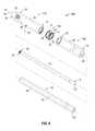
- FIG. 5is perspective view with parts separated of the microwave field-detecting needle assembly of FIG. 1 according to an embodiment of the present disclosure
- FIG. 7is perspective view of a portion of a needle assembly including a first outer-conductor structure coupled to the retaining portion and disposed around a distal portion of the inner-conductor pin shown in FIG. 6 according to an embodiment of the present disclosure
- FIG. 8is a perspective view of the portion of the needle assembly of FIG. 7 shown with a tubular sleeve member disposed around a length of the inner-conductor pin proximal to the threaded portion according to an embodiment of the present disclosure
- FIG. 9is a perspective view of the portion of the needle assembly of FIG. 8 shown with a junction structure disposed around a portion of the tubular sleeve member and threadedly coupled to the proximal end of the first outer-conductor structure according to an embodiment of the present disclosure;
- FIG. 10is a perspective view of the portion of the needle assembly of FIG. 9 shown with a second outer-conductor structure disposed around a proximal portion of the tubular sleeve member and threadedly coupled to the distal end of the junction structure, according to an embodiment of the present disclosure;
- FIG. 11is a perspective view of the portion of the needle assembly of FIG. 10 shown with a rectifier element disposed separately from and positioned above a rectifier-receiving recess defined in the junction structure according to an embodiment of the present disclosure;
- FIG. 12is a perspective view of the portion of the needle assembly of FIG. 11 shown with the rectifier element disposed in the rectifier-receiving recess according to an embodiment of the present disclosure
- FIG. 13is a perspective view of the portion of the needle assembly of FIG. 12 shown with an outer jacket disposed around the first outer-conductor structure, second outer-conductor structure and the junction structure according to an embodiment of the present disclosure;
- FIG. 14is a cross-sectional view of the portion of the needle assembly of FIG. 13 according to an embodiment of the present disclosure
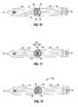
- FIG. 15is a schematically-illustrated representation of a standing wave coupled to the needle assembly of FIG. 13 according to an embodiment of the present disclosure
- FIG. 16is a perspective view of a first side of another embodiment of a needle assembly in accordance with the present disclosure.
- FIG. 17is a perspective view of a second side of the needle assembly of FIG. 16 according to an embodiment of the present disclosure.
- FIG. 18is a schematic perspective view of an electrosurgical system according to an embodiment of the present disclosure.
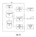
- FIG. 19is a block diagram of an embodiment of the electrosurgical power generating source of FIG. 18 in accordance with the present disclosure.
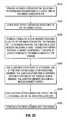
- FIG. 20is a flowchart illustrating a method of method of manufacturing a needle assembly according to an embodiment of the present disclosure
- FIG. 21is a flowchart illustrating a method of method of manufacturing a microwave field-detecting needle assembly according to an embodiment of the present disclosure.
- FIG. 22is a flowchart illustrating a method of adjusting an ablation field radiating into tissue.
- proximalrefers to that portion of the apparatus, or component thereof, closer to the user and the term “distal” refers to that portion of the apparatus, or component thereof, farther from the user.
- a phrase in the form “A/B”means A or B.
- a phrase in the form “A and/or B”means “(A), (B), or (A and B)”.
- a phrase in the form “at least one of A, B, or C”means “(A), (B), (C), (A and B), (A and C), (B and C), or (A, B and C)”.
- Electromagnetic energyis generally classified by increasing energy or decreasing wavelength into radio waves, microwaves, infrared, visible light, ultraviolet, X-rays and gamma-rays.
- microwavegenerally refers to electromagnetic waves in the frequency range of 300 megahertz (MHz) (3 ⁇ 10 8 cycles/second) to 300 gigahertz (GHz) (3 ⁇ 10 11 cycles/second).
- transmission linegenerally refers to any transmission medium that can be used for the propagation of signals from one point to another.
- ablation proceduregenerally refers to any ablation procedure, such as, for example, microwave ablation, radiofrequency (RF) ablation, or microwave or RF ablation-assisted resection.
- energy applicatorgenerally refers to any device that can be used to transfer energy from a power generating source, such as a microwave or RF electrosurgical generator, to tissue.
- a power generating sourcesuch as a microwave or RF electrosurgical generator
- rectifiergenerally refers to circuit components that allow more electric current to flow in one direction than in the other. Rectifiers may be made of solid-state diodes, vacuum-tube diodes, mercury-arc valves, and other components. Processes that make use of rectifiers include rectification, which, simply defined, is the conversion of alternating current (AC) to direct current (DC). As it is used in this description, “diode” generally refers to electronic devices that allow electric current to flow in only one direction, while inhibiting current flow in the other. For the purposes herein, the term “diode” is interchangeable with the term “rectifier”.
- printed circuit boardgenerally refers to any and all systems that provide, among other things, mechanical support to electrical components, electrical connection to and between these electrical components, combinations thereof, and the like.
- lengthmay refer to electrical length or physical length.
- electrical lengthis an expression of the length of a transmission medium in terms of the wavelength of a signal propagating within the medium. Electrical length is normally expressed in terms of wavelength, radians or degrees. For example, electrical length may be expressed as a multiple or sub-multiple of the wavelength of an electromagnetic wave or electrical signal propagating within a transmission medium. The wavelength may be expressed in radians or in artificial units of angular measure, such as degrees.
- the electric length of a transmission mediummay be expressed as its physical length multiplied by the ratio of (a) the propagation time of an electrical or electromagnetic signal through the medium to (b) the propagation time of an electromagnetic wave in free space over a distance equal to the physical length of the medium.
- the electrical lengthis in general different from the physical length. By the addition of an appropriate reactive element (capacitive or inductive), the electrical length may be made significantly shorter or longer than the physical length.
- microwave field-detecting needle assembliesadapted to enable physicians to detect microwave field intensity in proximity to an energy-delivery devices, e.g., to ensure patient and/or physician safety and/or to provide for improved control over applied energy.
- Microwave field-detecting needle assembly embodimentsmay be implemented as passive devices.
- microwave field-detecting needle assembliesmay be monitored by a stand-alone control unit.
- Microwave field-detecting needle assembly embodimentsmay be integrated into a feedback control loop within a microwave ablation control system.
- Microwave field-detecting needle assembly embodimentsmay be suitable for utilization in open surgical applications. Embodiments may be used in minimally invasive procedures, e.g., endoscopic and laparoscopic surgical procedures. Portions of the presently-disclosed microwave field-detecting needle assemblies may be disposable, replaceable and/or reusable.
- microwave field-detecting needle assemblyVarious embodiments of the presently-disclosed microwave field-detecting needle assembly are adapted to be coupled in communication with a stand-alone control unit (e.g., 28 shown in FIG. 4 ).
- a stand-alone control unite.g., 28 shown in FIG. 4 .
- An electrosurgical system(also referred to herein as a “microwave ablation control system”) including an energy-delivery device(s) and one or more microwave field-detecting needle assemblies according to various embodiments is designed and configured to operate at frequencies between about 300 MHz and about 10 GHz.
- the presently-disclosed microwave ablation control systemsare suitable for microwave or RF ablation and for use to pre-coagulate tissue for microwave or RF ablation-assisted surgical resection.
- the teachings of the present disclosuremay also apply to electromagnetic radiation at RF frequencies or at other frequencies.
- FIGS. 1 through 3show an embodiment of a microwave field-detecting needle assembly (shown generally as 100 in FIG. 1 ).
- Microwave field-detecting needle assembly 100generally includes a handle assembly 170 and a needle assembly 110 .
- FIG. 3shows a schematic diagram of an electric circuit 300 (shown in phantom lines in FIG. 1 ) disposed within a handle housing 174 of the handle assembly 170 .
- Needle assembly 110is shown with parts separated in FIG. 5 .
- the needle assembly 110generally includes a distal portion 130 , a proximal portion 160 , and a junction member 150 disposed between the distal portion 130 and the proximal portion 160 .
- the distal portion 130 and the proximal portion 160align at the junction member 150 , which is generally made of a dielectric material.
- the junction member 150may be configured to be mechanically coupleable (e.g., threadedly coupleable) to the distal portion 130 and/or the proximal portion 160 .
- the distal portion 130includes a first outer-conductor structure 30
- the proximal portion 160includes a second outer-conductor structure 60
- the junction member 150includes a junction structure 50 .
- the shape and size of the needle assembly 110 and the handle assembly 170may be varied from the configuration depicted in FIG. 1 .
- needle assembly 110includes an inner-conductor pin 20 , a tubular sleeve member 40 disposed around at least a portion of the inner-conductor pin 20 , a first outer-conductor structure 30 , a second outer-conductor structure 60 , a junction structure 50 disposed between the first outer-conductor structure 30 and the second outer-conductor structure 60 , and one or more rectifiers 58 disposed in one or more recesses 56 defined in the junction structure 50 .
- Inner-conductor pin 20has a suitable outer diameter “D 1 ” ( FIG. 5 ).
- the distal end 22 of the inner-conductor pin 20includes a retaining portion 23 .
- the retaining portion 23may be externally threaded.
- the proximal end 21 of the inner-conductor pin 20is coupled to the handle assembly 170 .
- Inner-conductor pin 20may be electrically coupled to an electric circuit 300 , which is described in more detail later in this disclosure, disposed within the handle assembly 170 .
- Various components of the needle assembly 110may be formed of suitable, electrically-conductive materials, e.g., copper, gold, silver, or other conductive metals or metal alloys having similar conductivity values. Electrically-conductive materials used to form the inner-conductor pin 20 , the first outer-conductor structure 30 and/or the second outer-conductor structure 60 may be plated with other materials, e.g., other conductive materials, such as gold or silver, to improve their properties, e.g., to improve conductivity, decrease energy loss, etc.
- suitable, electrically-conductive materialse.g., copper, gold, silver, or other conductive metals or metal alloys having similar conductivity values.
- Electrically-conductive materials used to form the inner-conductor pin 20 , the first outer-conductor structure 30 and/or the second outer-conductor structure 60may be plated with other materials, e.g., other conductive materials, such as gold or silver, to improve their properties, e.g., to improve conductivity, decrease
- the inner-conductor pin 20 , the first outer-conductor structure 30 and/or the second outer-conductor structure 60may be formed of a rigid, electrically-conductive material, such as stainless steel.
- the inner-conductor pin 20is formed from a first electrically-conductive material (e.g., stainless steel) and the first outer-conductor structure 30 and/or the second outer-conductor structure 60 is formed from a second electrically-conductive material (e.g., copper).
- the inner-conductor pin 20 , the first outer-conductor structure 30 and/or the second outer-conductor structure 60may be formed of a flexible, electrically-conductive material, such as titanium.
- Tubular sleeve member 40includes a body 44 that defines a longitudinally-extending internal bore or chamber 45 configured to receive at least a portion of the inner-conductor pin 20 therein.
- Body 44has a suitable outer diameter “D 2 ” as shown in FIG. 5 .
- Tubular sleeve member 40may be formed from any suitable dielectric material, including, but not limited to, ceramics, mica, polyethylene, polyethylene terephthalate, polyimide, polytetrafluoroethylene (PTFE) (e.g., TEFLON®, manufactured by E. I. du Pont de Nemours and Company of Wilmington, Del., United States), glass, metal oxides or other suitable insulator, and may be formed in any suitable mariner.
- PTFEpolytetrafluoroethylene
- tubular sleeve member 40is disposed around a length of the inner-conductor pin 20 proximal to the retaining portion 23 .
- junction member embodiments in accordance with the present disclosureinclude a junction structure having one or more recesses (e.g., one recess 56 shown in FIGS. 2 , 5 and 9 - 12 , or a plurality of recesses 1656 shown in FIG. 16 ) defined therein.
- the recess 56is configured to receive a rectifier 58 therein.
- Rectifier 58may include one or more diodes, e.g., Zener diode, Schottky diode, tunnel diode and the like, and/or other suitable component(s) capable of converting AC to DC.
- Junction structure 50may be formed of any suitable elastomeric or ceramic dielectric material by any suitable process.
- the junction structure 50may be formed of a composite material having low electrical conductivity, e.g., glass-reinforced polymers.
- the junction structure 50is formed by over-molding and includes a thermoplastic elastomer, such as, for example, polyether block amide (e.g., PEBAX®, manufactured by The Arkema Group of Colombes, France), polyetherimide (e.g., ULTEM® and/or EXTEM®, manufactured by SABIC Innovative Plastics of Saudi Arabia) and/or polyimide-based polymer (e.g., VESPEL®, manufactured by E. I. du Pont de Nemours and Company of Wilmington, Del., United States).
- Junction structure 50may be formed using any suitable over-molding compound by any suitable process, and may include use of a ceramic substrate.
- electric circuit 300is disposed within the handle housing 174 of the handle assembly 170 .
- electric circuit 300may be formed as a printed circuit board, with components thereof connected by traces on an epoxy resin substrate.
- Handle housing 174provides a ground reference “G” for the circuit 300 .
- An indicator unit 4or component thereof, is coupled to the handle housing 174 .
- Indicator unit 4may include audio and/or visual indicator devices to provide information/feedback to a user.
- the indicator unit 4is adapted to generate a visual signal and includes a light source, such as a light-emitting diode 9 .
- Indicator unit 4may additionally, or alternatively, be adapted to generate an audio signal and may include an audio circuit with a speaker (not shown).
- the proximal end 21 of the inner-conductor pin 20(shown in cross section in FIG. 3 ) is electrically coupled to a first terminal of a filter circuit 5 .
- Filter circuit 5includes a second terminal electrically coupled to an amplifier circuit 7 , and may include a ground terminal electrically coupled to the handle housing 174 .
- Filter circuit 5may include an RF filter block.
- the filter circuit 5may be an inductor-resistor-capacitor (LCR) low-pass filter that is adapted to convert a rectified sinusoidal waveform from the rectifier element(s) 58 into an electrical signal, which may be a DC voltage signal representative of the detected microwave field intensity.
- LCRinductor-resistor-capacitor
- circuit 300includes a power source 3 that is electrically coupled to the amplifier circuit 7 .
- Power source 3may include a ground terminal electrically coupled to the handle housing 174 .
- Power source 3may include any combination of battery cells, a battery pack, fuel cell and/or high-energy capacitor.
- a battery packmay include one or more disposable batteries. In such case, the one or more disposable batteries may be used as a primary power source for the amplifier circuit 7 .
- a transmission line 11( FIG. 1 ) is provided to connect the microwave field-detecting needle assembly to a line source voltage or external power source (shown generally as 2 in FIG. 1 ), in which case a battery pack may be provided for use as a backup power source.
- FIG. 4schematically illustrates an embodiment of a microwave field-detecting system (shown generally as 10 ) that includes a stand-alone control unit 28 operably coupled to a microwave field-detecting needle assembly 400 .
- Microwave field-detecting needle assembly 400is similar to the microwave field-detecting needle assembly 100 of FIG. 1 , except that microwave field-detecting needle assembly 400 includes a handle assembly 470 configured to operably couple the needle assembly 110 to a cable assembly 15 .
- Cable assembly 15may be any suitable transmission line. Cable assembly 15 may include a proximal end 14 suitable for connection to the control unit 28 .
- Handle assembly 470includes an indicator unit 412 that is suitably configured to provide information/feedback to a user.
- Indicator unit 412is similar to the indicator unit 4 shown in FIG. 3 and further description thereof is omitted in the interests of brevity.
- the shape and size of the handle assembly 470 and the indicator unit 412may be varied from the configuration depicted in FIG. 4 .
- Control unit 28may include a user interface 27 in operable communication with a processor unit 29 .
- User interface 27may include audio and/or visual indicator devices to provide information/feedback to a user.
- Processor unit 29may be any type of computing device, computational circuit, or any type of processor or processing circuit capable of executing a series of instructions that are stored in a memory (not shown) associated with the processor unit 29 .
- Processor unit 29may be adapted to run an operating system platform and application programs.
- Microwave field-detecting needle assembly 400 and the control unit 28may utilize wired communication and/or wireless communication. In the embodiment illustrated in FIG. 4 , the microwave field-detecting needle assembly 400 is electrically connected via the cable assembly 15 to a connector 16 , which further operably connects the microwave field-detecting needle assembly 400 to a terminal 19 of the control unit 28 .
- FIG. 5shows the needle assembly 110 with parts separated in accordance with the present disclosure.
- the needle assembly 110includes an inner-conductor pin 20 , first outer-conductor structure 30 , second outer-conductor structure 60 , tubular sleeve member 40 , junction structure 50 , and one or more rectifiers 58 .
- the first outer-conductor structure 30defines a first chamber portion 36 and a second chamber portion 35 .
- First chamber portion 36is disposed at the distal end 32 of the first outer-conductor structure 30 .
- Second chamber portion 35is disposed in communication with the first chamber portion 36 and includes an opening 38 disposed at the proximal end 31 of the first outer-conductor structure 30 .
- the first chamber portion 36is configured to matingly engage, e.g., threadedly engage, with the retaining portion 23 of inner-conductor pin 20
- the second chamber portion 35is configured to receive at least a portion of the tubular sleeve member 40 therein.
- First outer-conductor structure 30may be provided with an end cap 37 .
- End cap 37generally includes a tapered portion 33 , which may terminate in a sharp tip 34 to allow for insertion into tissue with minimal resistance.
- Tapered portion 33may include other shapes, such as, for example, a tip 34 that is rounded, flat, square, hexagonal, or cylindroconical.
- End cap 37may be formed of a material having a high dielectric constant, and may be a trocar, e.g., a zirconia ceramic.
- First outer-conductor structure 30 and end cap 37may be formed separately from each other, and coupled together, e.g., with the aid of adhesive or solder.
- First outer-conductor structure 30 and end cap 37may form a single, unitary structure. The shape and size of the first outer-conductor structure 30 and the end cap 37 may be varied from the configuration depicted in FIG. 5 .
- Second outer-conductor structure 60defines a longitudinally-extending internal bore or chamber 65 that extends from the proximal end 61 to the distal end 62 of the second outer-conductor structure 60 .
- Chamber 65is configured to receive at least a portion of the tubular sleeve member 40 therein.
- Junction structure 50defines a longitudinally-extending internal bore or chamber 55 therein and generally includes a distal end 52 adapted for connection to the first outer-conductor structure 30 and a proximal end 51 adapted for connection to the second outer-conductor structure 60 .
- the junction structure 50includes a distal end 52 provided with a series of external threads configured to matingly engage with a series of internal threads disposed at the proximal end 31 of the first outer-conductor structure 30 , and a proximal end 51 provided with a series of external threads configured to matingly engage with a series of internal threads disposed at the distal end 62 of the second outer-conductor structure 60 .
- the shape and size of the junction structure 50may be varied from the configuration depicted in FIG. 5 .
- FIGS. 6 through 13show a sequentially-illustrated, assembly of components forming the needle assembly 110 in accordance with the present disclosure.
- FIG. 6shows the inner-conductor pin 20 .
- inner-conductor pin 20may be formed of any suitable electrically-conductive material (e.g., metal such as stainless steel, aluminum, titanium, copper, etc.) of any suitable length.
- the shape and size of the inner-conductor pin 20may be varied from the configuration depicted in FIG. 6 .
- inner-conductor pin 20includes a distal end 22 including a retaining portion 23 that is configured to be connectable, e.g., electrically and mechanically, to the first outer-conductor structure 30 .
- the retaining portion 23is provided with a series of external threads configured to matingly engage with a series of internal threads disposed within the first chamber portion 36 of the first outer-conductor structure 30 .
- a longitudinal axis “A”-A′′is defined by the inner-conductor pin 20 .
- tubular sleeve member 40is configured to be receivable within second chamber portion 35 of the first outer-conductor structure 30 , chamber 55 of the junction structure 50 and chamber 60 of the second outer-conductor structure 60 .
- FIG. 8shows the tubular sleeve member 40 joined together with the inner-conductor pin 20 and the first outer-conductor structure 30 such that the tubular sleeve member 40 is coaxially-disposed about the length of the inner conductor 20 proximal to the retaining portion 23 and disposed at least in part within the second chamber portion 35 of the first outer-conductor structure 30 .
- tubular sleeve member 40is positioned around the inner-conductor pin 20 after the retaining portion 23 is coupled to the end cap 37 , e.g., as shown in FIG. 8 .
- Tubular sleeve member 40may, alternatively, be positioned, formed, adhered or otherwise disposed around at least a portion of the inner-conductor pin 20 prior to the introduction of the inner-conductor pin 20 into the second chamber portion 35 of the first outer-conductor structure 30 .
- FIG. 9shows the portion of the needle assembly of FIG. 8 shown with junction structure 50 disposed around a portion of the tubular sleeve member 40 and coupled to the first outer-conductor structure 30 .
- Junction structure 50may be coupled to the first outer-conductor structure 30 by any suitable manner of connection.
- junction structure 50includes a distal end 52 provided with a series of external threads configured to matingly engage with a series of internal threads disposed at the proximal end 31 of the first outer-conductor structure 30 .
- junction structure 50 and the first outer-conductor structure 30may be assembled together with the aid of alignment pins, snap-like interfaces, tongue and groove interfaces, locking tabs, adhesive ports, etc., utilized either alone or in combination for assembly purposes.
- FIG. 10shows the portion of the needle assembly of FIG. 9 shown with second outer-conductor structure 60 disposed around a portion of the tubular sleeve member 40 and coupled to the proximal end 51 of the junction structure 50 .
- second outer-conductor structure 60includes a distal end 62 provided with a series of internal threads configured to matingly engage with a series of external threads disposed at the proximal end 51 of the junction structure 50 .
- FIG. 11shows the portion of the needle assembly of FIG. 10 shown with rectifier element 58 disposed above rectifier-receiving recess 56 in the junction structure 50 .
- Rectifier element 58includes a first lead wire or pin 59 a (also referred to herein as a “terminal”) and a second lead wire or pin 59 b .
- Rectifier-receiving recess 56may be configured to receive the rectifier element 58 such that the first pin 59 a and the second pin 59 b are substantially aligned with the longitudinal axis “A”-A′′ defined by the inner-conductor pin 20 .
- FIG. 12shows the portion of the needle assembly of FIG. 11 shown with the rectifier element 58 disposed in the rectifier-receiving recess 56 .
- First pin 59 ais electrically coupled to the first outer-conductor structure 30 by any suitable manner of electrical connection, e.g., soldering, welding, or laser welding.
- Second pin 59 bis electrically coupled to the second outer-conductor 60 by any suitable manner of electrical connection.
- FIG. 13shows the portion of the needle assembly of FIG. 12 shown with an outer jacket 90 disposed around the first outer-conductor structure 30 , the second outer-conductor structure 60 , and the junction structure 50 .
- Outer jacket 90may be formed of any suitable material, such as, for example, polymeric or ceramic materials.
- the outer jacket 90may be applied by any suitable method, such as, for example, heat-shrinkage, extrusion, molding, coating, spraying, dipping, powder coating, baking and/or film deposition, or other suitable process.
- outer jacket 90covers the rectifier element 58 .
- the outer jacket 90may include an opening (not shown) configured to expose the rectifier element 58 and/or the junction structure 50 , or portion thereof.
- the position of the junction structure 50 and rectifier element 58is one factor in determining the operational frequency of the microwave field-detecting needle assembly 100 in a given material, e.g., tissue.
- the junction structure 50may be positioned at a location of high voltage along the expected standing wave that couples onto the probe, such as illustratively shown in FIG. 15 .
- fields 1501 , 1502couple onto the microwave field-detecting needle assembly 100 from the energy supplied by an energy-delivery device (e.g., 12 shown in FIG. 18 ), e.g., a microwave ablation probe.
- FIGS. 16 and 17show a needle assembly (shown generally as 1610 ) according to an embodiment of the present disclosure that is adapted to enable multi-frequency operation and/or multiple wavelength operation.
- Needle assembly 1610is similar to the needle assembly 110 shown in FIGS. 1 , 2 and 5 , except for the configuration of the junction structure 1650 , the first outer-conductor structure 1630 and the second outer-conductor structure 1660 , and the plurality of rectifiers 1658 disposed in the plurality of recesses 1656 .
- Needle assembly 1610includes a junction structure 1650 configured to separate a first outer-conductor structure 1630 and a second outer-conductor structure 1660 in a diagonal fashion.
- First outer-conductor structure 1630 and the second outer-conductor structure 1660may be formed of any suitable electrically-conductive material, e.g., metal such as stainless steel, aluminum, titanium, copper, or the like.
- the first outer-conductor structure 1630is constructed from stainless steel, and may be coated in a high electrical conductivity, corrosion-resistant metal, e.g., silver, or the like.
- the junction structure 1650includes a plurality of recesses 1656 defined therein, wherein each recess 1656 is defined in a different outer-peripheral portion of the junction structure 1650 and configured to receive a rectifier 1658 therein.
- Rectifier 1658is similar to the rectifier 58 shown in FIG. 2 and further description thereof is omitted in the interests of brevity.
- Each rectifier 1658may be configured to operate efficiently at separate frequencies allowing for probe use at multiple frequencies.
- FIG. 18shows an electrosurgical system 1800 according to an embodiment of the present disclosure that includes an energy applicator or probe 12 operably coupled to an electrosurgical power generating source 26 .
- the probe 12may be coupled in fluid communication with a coolant supply system (not shown).
- Electrosurgical system 1800(also referred to herein as a “microwave ablation control system”) generally includes one or more microwave field-detecting needle assemblies 100 and a control unit 24 in operable communication with the one or more microwave field-detecting needle assemblies 100 .
- Control unit 24 and the one or more microwave field-detecting needle assemblies 100may utilize wired communication and/or wireless communication.
- Control unit 24is similar to the control unit 28 shown in FIG. 4 and further description thereof is omitted in the interests of brevity.
- Electrosurgical system 1800may include a feedback loop 18 suitable for use in controlling an energy applicator or probe 12 based on one or more electrical signals transmitted by one or more microwave field-detecting needle assemblies 100 .
- Feedback loop 18may utilize a cable connection and/or a wireless connection, e.g., a radiofrequency or infrared link.
- the microwave ablation control system 1800may adjust the ablation field radiating about at least a portion of the energy applicator 12 into tissue by adjusting one or more operating parameters associated with the electrosurgical power generating source 26 based on one or more electrical signals transmitted by one or more microwave field-detecting needle assemblies 100 .
- the plurality of microwave field-detecting needle assemblies 100 in operable communication with the control unit 24are operable coupled via the feedback loop 18 to the electrosurgical power generating source 26 .
- Examples of operating parameters associated with the electrosurgical power generating source 26include temperature, impedance, power, current, voltage, mode of operation, and duration of application of electromagnetic energy.
- electrosurgical system embodimentsmay utilize single or multiple energy applicators (or applicator arrays) and one or more microwave field-detecting needle assemblies.
- the single or multiple energy applicators and the one or more microwave field-detecting needle assembliesmay be arranged in any suitable configuration.
- Electrosurgical power generating source 26may be any generator suitable for use with electrosurgical devices, and may be configured to provide various frequencies of electromagnetic energy. In some embodiments, the electrosurgical power generating source 26 is configured to provide microwave energy at an operational frequency from about 300 MHz to about 10 GHz. In other embodiments, the electrosurgical power generating source 26 is configured to provide electrosurgical energy at an operational frequency from about 400 KHz to about 500 KHz.
- the electrosurgical power generating source 26is configured or set to a predetermined setting.
- electrosurgical power generating source 26may be set to a predetermined temperature, such as a temperature that may be used for the treatment of pain (e.g., about 42° C. or about 80° C.), a predetermined waveform, a predetermined duty cycle, a predetermined time period or duration of activation, etc.
- Electrosurgical power generating source 26may include a user interface 25 ( FIG. 19 ) in operable communication with a processor unit 82 ( FIG. 19 ).
- Processor unit 82which is described in more detail with respect to FIG. 19 , may be any type of computing device, computational circuit, or any type of processor or processing circuit capable of executing a series of instructions that are stored in a memory.
- a physicianmay input via the user interface 25 a selected power output, and the microwave ablation control system 1800 controls the probe 12 to automatically adjust the ablation volume by changing the operating frequency of the probe 12 , e.g., based on at least one electrical signal transmitted by the one or more microwave field-detecting needle assemblies 100 .
- a physicianmay input via the user interface 25 a selected power output, and the microwave ablation control system 1800 controls the ablation field radiating about at least a portion of the energy applicator 12 into tissue based on one or more electrical signals transmitted by one or more microwave field-detecting needle assemblies 100 , e.g., by rotation of a energy applicator with a directional radiation pattern to avoid ablating sensitive structures, such as large vessels, healthy organs or vital membrane barriers and/or by controlling the electrosurgical power generating source 26 operatively associated with an energy applicator 12 .
- one or more microwave field-detecting needle assemblies 100may be inserted into tissue “T” and/or placed adjacent a sensitive structure “S”, and/or one or more microwave field-detecting needle assemblies 100 may be inserted into the abdominal wall “W” and/or into the abdominal cavity “C”.
- Probe 12is inserted into tissue “T” and/or placed adjacent to a lesion “L”.
- Ultrasound or computed tomography (CT) guidancemay be used to accurately guide the probe 12 into the area of tissue to be treated.
- Probe 12 and one or more microwave field-detecting needle assemblies 100may be placed percutaneously or surgically, e.g., using conventional surgical techniques by surgical staff. After the one or more microwave field-detecting needle assemblies 100 and the probe 12 are positioned, microwave energy is supplied to the probe 12 .
- CTcomputed tomography
- a clinicianmay pre-determine the length of time that microwave energy is to be applied.
- Application durationmay depend on many factors such as tumor size and location and whether the tumor was a secondary or primary cancer.
- the duration of microwave energy application using the probe 12may depend on the progress of the heat distribution within the tissue area that is to be destroyed and/or the surrounding tissue.
- Treatment of certain tumorsmay involve probe repositioning during the ablation procedure, such as where the tumor is larger than the probe or has a shape that does not correspond with available probe geometry or radiation pattern.
- FIG. 19is a block diagram showing one embodiment of the electrosurgical power generating source 26 of FIG. 18 .
- the generator module 86is configured to provide energy of about 915 MHz.
- Generator module 86may additionally, or alternatively, be configured to provide energy of about 2450 MHz (2.45 GHz).
- the present disclosurecontemplates embodiments wherein the generator module 86 is configured to generate a frequency other than about 915 MHz or about 2450 MHz, and embodiments wherein the generator module 86 is configured to generate variable frequency energy.
- Electrosurgical power generating source 26includes a processor 82 that is operably coupled to the user interface 25 .
- Processor 82may include any type of computing device, computational circuit, or any type of processor or processing circuit capable of executing a series of instructions that are stored in a memory, e.g., storage device 88 or external device 91 .
- storage device 88is operably coupled to the processor 82 , and may include random-access memory (RAM), read-only memory (ROM), and/or non-volatile memory (NV-RAM, Flash, and disc-based storage).
- Storage device 88may include a set of program instructions executable on the processor 82 for executing a method for displaying and controlling ablation patterns in accordance with the present disclosure.
- Electrosurgical power generating source 26may include a data interface 90 that is configured to provide a communications link to an external device 91 .
- the data interface 90may be any of a USB interface, a memory card slot (e.g., SD slot), and/or a network interface (e.g., 100BaseT Ethernet interface or an 802.11 “Wi-Fi” interface.)
- External device 91may be any of a USB device (e.g., a memory stick), a memory card (e.g., an SD card), and/or a network-connected device (e.g., computer or server).
- Electrosurgical power generating source 26may also include a database 84 that is configured to store and retrieve energy applicator data, e.g., parameters associated with one or energy applicators (e.g., 12 shown in FIGS. 18 and 19 ).
- Parameters stored in the database 84 in connection with an energy applicator, or energy applicator arraymay include, but are not limited to, energy applicator (or applicator array) identifier, energy applicator (or applicator array) dimensions, a frequency, an ablation length, an ablation diameter, a temporal coefficient, a shape metric, and/or a frequency metric.
- ablation pattern topologymay be included in the database 84 , e.g., a wireframe model of an applicator array and/or an ablation pattern associated therewith and/or an arrangement of microwave field-detecting needle assemblies for use in connection with one or more energy applicators.
- Database 84may also be maintained at least in part by data provided by the external device 91 via the data interface 90 .
- data associated with energy applicator 12may be uploaded from an external device 91 to the database 84 via the data interface 90 .
- Energy applicator datamay additionally, or alternatively, be manipulated, e.g., added, modified, or deleted, in accordance with data and/or instructions stored on the external device 91 .
- the set of energy applicator data represented in the database 84is automatically synchronized with corresponding data contained in the external device 91 in response to the external device 91 being coupled (e.g., physical coupling and/or logical coupling) to the data interface 90 .
- Processor 82is programmed to enable a user, via the user interface 25 and/or a display device (not shown), to view at least one ablation pattern and/or other data corresponding to an energy applicator or an applicator array.
- a physicianmay determine that a substantially spherical ablation pattern is necessary.
- the physicianmay activate a “select ablation shape” mode of operation for electrosurgical power generating source 26 , preview an energy applicator array by reviewing graphically and textually presented data, optionally, or alternatively, manipulate a graphic image by, for example, rotating the image, and select an energy applicator or an applicator array, based upon displayed parameters.
- the selected energy applicator(s)may then be electrically coupled to the electrosurgical power generating source 26 for use therewith.
- Electrosurgical power generating source 26may include an actuator 87 .
- Actuator 87may be any suitable actuator, e.g., a footswitch, a handswitch, an orally-activated switch (e.g., a bite-activated switch and/or a breath-actuated switch), and the like.
- Actuator 87may be operably coupled to the processor 82 by a cable connection (e.g., 83 shown in FIG. 18 ) or a wireless connection, e.g., a radiofrequency or infrared link.
- a physicianmay input via the user interface 25 an applicator array parameter to cause the electrosurgical power generating source 26 to present one or more electromagnetic energy delivery devices corresponding thereto and/or one or more microwave field-detecting needle assemblies for use therewith.
- a physicianmay require a 3.0 cm ⁇ 3.0 cm ⁇ 3.0 cm ablation pattern, and provide an input corresponding thereto.
- the electrosurgical power generating source 26may preview a corresponding subset of available electromagnetic energy delivery devices that match or correlate to the inputted parameter.
- a physicianmay input via the user interface 25 a selected power output, and the electrosurgical system 1800 controls the energy applicator 12 to adjust the ablation field radiating about at least a portion of the energy applicator 12 into tissue based on at least one electrical signal transmitted by the one or more microwave field-detecting needle assemblies.
- FIG. 20a method of manufacturing a needle assembly in accordance with the present disclosure is described with reference to FIG. 20
- a method of manufacturing a microwave field-detecting needle assembly in accordance with the present disclosureis described with reference to FIG. 21
- a method of adjusting an ablation field radiating into tissueis described with reference to FIG. 22 . It is to be understood that the steps of the methods provided herein may be performed in combination and in a different order than presented herein without departing from the scope of the disclosure.
- FIG. 20is a flowchart illustrating a method of manufacturing a needle assembly according to an embodiment of the present disclosure.
- step 2010an inner-conductor pin 20 is provided.
- a retaining portion 23is disposed at a distal end 22 of the inner-conductor pin 20 .
- step 2020a first outer-conductor structure 30 is joined to the retaining portion 23 .
- a tubular sleeve member 40is positioned overlying a length of the inner-conductor pin 20 proximal to the retaining portion 23 .
- the tubular sleeve member 40includes a longitudinally-extending internal chamber 45 configured to receive at least a portion of the inner-conductor pin 20 therein.
- a junction structure 50is joined to the proximal end 31 of the first outer-conductor structure 30 , whereby the junction structure 50 is disposed around a portion of the tubular sleeve member 40 .
- the junction structure 50includes a recess 56 defined therein.
- the distal end 52 of the junction member 50may be provided with a series of external threads configured to matingly engage with a series of internal threads disposed at the proximal end 31 of the first outer-conductor structure 30 .
- a second outer-conductor structure 60is joined to the proximal end 51 of the junction structure 50 .
- the proximal end 51 of the junction member 50may be provided with a series of external threads configured to matingly engage with a series of internal threads disposed at the distal end 62 of the second outer-conductor structure 60 .
- a rectifier element 58is positioned into the recess 56 .
- the rectifier element 58includes a first terminal 59 a and a second terminal 59 b .
- the first terminal 59 amay be electrically coupled to the first outer-conductor structure 30 and the second terminal 59 b may be electrically coupled to the second outer-conductor structure 60 , e.g., by solder or other suitable electrical connection.
- FIG. 21is a flowchart illustrating a method of manufacturing a microwave field-detecting needle assembly according to an embodiment of the present disclosure.
- a handle assembly 170is provided.
- An electric circuit 300is disposed within the handle assembly 170 .
- a needle assembly 110is provided.
- the needle assembly 110includes a first outer-conductor structure 30 coupled to an inner-conductor pin 20 , a junction structure 50 disposed between the first outer-conductor structure 30 and a second outer-conductor structure 60 , and a rectifier element 58 disposed in a recess 56 defined in the junction structure 50 .
- a first terminal 59 a of the rectifier element 58is electrically coupled to the first outer-conductor structure 30
- a second terminal 59 bis electrically coupled to the second outer-conductor structure 60 .
- step 2130the inner-conductor pin 20 and the second outer-conductor structure 60 are electrically coupled to an electric circuit 300 disposed within the handle assembly 170 .
- FIG. 22is a flowchart illustrating a method of adjusting an ablation field radiating into tissue according to an embodiment of the present disclosure.
- an energy applicator 12is provided in step 2210 .
- one or more microwave field-detecting needle assemblies 100are provided in step 2220 .
- Each microwave field-detecting needle assembly 100includes one or more rectifier elements 58 capable of detecting microwave field intensity via rectification.
- the energy applicator 12 and the one or more microwave field-detecting needle assemblies 100are positioned in tissue.
- the energy applicator 12may be inserted directly into tissue, inserted through a lumen, e.g., a vein, needle, endoscope or catheter, placed into the body during surgery by a clinician, or positioned in the body by other suitable methods known in the art.
- the energy applicator 12may be configured to operate with a directional radiation pattern.
- the one or more microwave field-detecting needle assemblies 100may be positioned in material, e.g., tissue, by any suitable method and arranged in any configuration (e.g., configuration shown in FIG. 18 ).
- step 2240energy is transmitted from an energy source 26 through the energy applicator 12 to generate an ablation field radiating about at least a portion of the energy applicator 12 into tissue.
- the energy source 26may be any suitable electrosurgical generator for generating an output signal.
- the energy source 26is a microwave energy source, and may be configured to provide microwave energy at an operational frequency from about 300 MHz to about 10 GHz.
- the ablation field radiating about at least the portion of the energy applicator 12 into tissueis adjusted based on at least one electrical signal transmitted by the one or more microwave field-detecting needle assemblies 100 .
- adjusting the ablation field radiating about at least the portion of the energy applicator 12 into tissuemay include adjusting at least one operating parameter associated with the energy source 26 based on the at least one electrical signal transmitted by the one or more microwave field-detecting needle assemblies 100 .
- operating parameters associated with the energy source 26include temperature, impedance, power, current, voltage, mode of operation, and duration of application of electromagnetic energy.
- the above-described microwave field-detecting needle assemblyenables physicians to detect field intensity in proximity to an energy-delivery device.
- the presently-disclosed microwave field-detecting needle assembly embodimentsmay allow the physician to determine if a microwave field is strong enough for the intended purpose or to achieve a desired surgical outcome.
- the presently-disclosed microwave field-detecting needle assembly embodimentsmay be suitable for utilization in minimally invasive procedures, e.g., endoscopic and laparoscopic surgical procedures.
- the above-described microwave field-detecting needle assembly embodimentsmay be suitable for utilization in open surgical applications.
- Various embodiments of the presently-disclosed microwave field-detecting needle assembly embodimentsmay allow the physician to determine when a microwave ablation probe is inserted to a proper depth within tissue, e.g., to reach the location of the ablation site and/or to avoid unintended field exposure.
- Various embodiments of the presently-disclosed microwave field-detecting needle assemblyare adapted to be coupled in communication with a stand-alone control unit.
- Electrosurgical systems including one or more microwave field-detecting needle assembliesmay protect sensitive structures, ensure expected field pattern and/or protect the abdominal wall from stray microwave fields.
- microwave field-detecting needle assembliesmay be used to detect microwave field intensity emitted by an energy applicator, and an electrical signal transmitted from the presently-disclosed microwave field-detecting needle assemblies may be used to control the positioning of an electrosurgical device (e.g., rotation of a energy applicator with a directional radiation pattern to avoid ablating sensitive structures, such as large vessels, healthy organs or vital membrane barriers), and/or control an electrosurgical power generating source operatively associated with an energy applicator.
- an electrosurgical devicee.g., rotation of a energy applicator with a directional radiation pattern to avoid ablating sensitive structures, such as large vessels, healthy organs or vital membrane barriers
Landscapes
- Health & Medical Sciences (AREA)
- Life Sciences & Earth Sciences (AREA)
- Physics & Mathematics (AREA)
- Engineering & Computer Science (AREA)
- Surgery (AREA)
- Biomedical Technology (AREA)
- Veterinary Medicine (AREA)
- Public Health (AREA)
- General Health & Medical Sciences (AREA)
- Animal Behavior & Ethology (AREA)
- Medical Informatics (AREA)
- Molecular Biology (AREA)
- Heart & Thoracic Surgery (AREA)
- Electromagnetism (AREA)
- Nuclear Medicine, Radiotherapy & Molecular Imaging (AREA)
- General Physics & Mathematics (AREA)
- Pathology (AREA)
- Otolaryngology (AREA)
- Biophysics (AREA)
- Radiology & Medical Imaging (AREA)
- Plasma & Fusion (AREA)
- Surgical Instruments (AREA)
- Radiation-Therapy Devices (AREA)
Abstract
Description
Claims (20)
Priority Applications (16)
| Application Number | Priority Date | Filing Date | Title |
|---|---|---|---|
| US12/977,415US9044253B2 (en) | 2010-12-23 | 2010-12-23 | Microwave field-detecting needle assemblies, methods of manufacturing same, methods of adjusting an ablation field radiating into tissue using same, and systems including same |
| US12/977,390US9055957B2 (en) | 2010-12-23 | 2010-12-23 | Microwave field-detecting needle assemblies, methods of manufacturing same, methods of adjusting an ablation field radiating into tissue using same, and systems including same |
| JP2011276800AJP6045149B2 (en) | 2010-12-23 | 2011-12-19 | Microwave field detection needle assembly, method for manufacturing the same, method for adjusting an irradiation ablation region in tissue using the same, and system including the same |
| EP14171496.4AEP2774652B1 (en) | 2010-12-23 | 2011-12-20 | System for adjusting an ablation field using a microwave field-detecting needle assembly |
| JP2011278058AJP5943597B2 (en) | 2010-12-23 | 2011-12-20 | Microwave field detection needle assembly, method for manufacturing the same, method for adjusting an irradiation ablation region in tissue using the same, and system including the same |
| EP11010024.5AEP2468359B1 (en) | 2010-12-23 | 2011-12-20 | System for adjusting an ablation field using a microwave field-detecting needle assembly |
| EP16157379.5AEP3050592B1 (en) | 2010-12-23 | 2011-12-20 | Microwave ablation system using a field-detecting needle |
| EP16194735.3AEP3159040A1 (en) | 2010-12-23 | 2011-12-21 | System for adjusting an ablation field using a microwave field detecting needle assembly |
| EP14151402.6AEP2722074B1 (en) | 2010-12-23 | 2011-12-21 | System using a microwave field-detecting needle assembly |
| EP11010046.8AEP2468360B1 (en) | 2010-12-23 | 2011-12-21 | System for adjusting an ablation field using a microwave field-detecting needle assembly |
| US14/727,950US9743985B2 (en) | 2010-12-23 | 2015-06-02 | Microwave field-detecting needle assemblies, methods of manufacturing same, methods of adjusting an ablation field radiating into tissue using same, and systems including same |
| US14/740,331US9375279B2 (en) | 2010-12-23 | 2015-06-16 | Methods of adjusting an ablation field radiating into tissue using microwave field-detecting needle assemblies |
| JP2016103191AJP6130554B2 (en) | 2010-12-23 | 2016-05-24 | Microwave field detection needle assembly, method for manufacturing the same, method for adjusting an irradiation ablation region in tissue using the same, and system including the same |
| US15/177,729US20160287330A1 (en) | 2010-12-23 | 2016-06-09 | Microwave field-detecting needle assemblies, methods of manufacturing same, methods of adjusting an ablation field radiating into tissue using same, and systems including same |
| JP2017079462AJP6383833B2 (en) | 2010-12-23 | 2017-04-13 | Microwave field detection needle assembly, method for manufacturing the same, method for adjusting an irradiation ablation region in tissue using the same, and system including the same |
| US15/674,767US20170333129A1 (en) | 2010-12-23 | 2017-08-11 | Microwave field-detecting needle assemblies, methods of manufacturing same, methods of adjusting an ablation field radiating into tissue using same, and systems including same |
Applications Claiming Priority (2)
| Application Number | Priority Date | Filing Date | Title |
|---|---|---|---|
| US12/977,415US9044253B2 (en) | 2010-12-23 | 2010-12-23 | Microwave field-detecting needle assemblies, methods of manufacturing same, methods of adjusting an ablation field radiating into tissue using same, and systems including same |
| US12/977,390US9055957B2 (en) | 2010-12-23 | 2010-12-23 | Microwave field-detecting needle assemblies, methods of manufacturing same, methods of adjusting an ablation field radiating into tissue using same, and systems including same |
Related Child Applications (1)
| Application Number | Title | Priority Date | Filing Date |
|---|---|---|---|
| US14/727,950ContinuationUS9743985B2 (en) | 2010-12-23 | 2015-06-02 | Microwave field-detecting needle assemblies, methods of manufacturing same, methods of adjusting an ablation field radiating into tissue using same, and systems including same |
Publications (2)
| Publication Number | Publication Date |
|---|---|
| US20120161786A1 US20120161786A1 (en) | 2012-06-28 |
| US9044253B2true US9044253B2 (en) | 2015-06-02 |
Family
ID=46319229
Family Applications (6)
| Application Number | Title | Priority Date | Filing Date |
|---|---|---|---|
| US12/977,390Active2034-04-16US9055957B2 (en) | 2010-12-23 | 2010-12-23 | Microwave field-detecting needle assemblies, methods of manufacturing same, methods of adjusting an ablation field radiating into tissue using same, and systems including same |
| US12/977,415Active2034-04-02US9044253B2 (en) | 2010-12-23 | 2010-12-23 | Microwave field-detecting needle assemblies, methods of manufacturing same, methods of adjusting an ablation field radiating into tissue using same, and systems including same |
| US14/727,950Expired - Fee RelatedUS9743985B2 (en) | 2010-12-23 | 2015-06-02 | Microwave field-detecting needle assemblies, methods of manufacturing same, methods of adjusting an ablation field radiating into tissue using same, and systems including same |
| US14/740,331Expired - Fee RelatedUS9375279B2 (en) | 2010-12-23 | 2015-06-16 | Methods of adjusting an ablation field radiating into tissue using microwave field-detecting needle assemblies |
| US15/177,729AbandonedUS20160287330A1 (en) | 2010-12-23 | 2016-06-09 | Microwave field-detecting needle assemblies, methods of manufacturing same, methods of adjusting an ablation field radiating into tissue using same, and systems including same |
| US15/674,767AbandonedUS20170333129A1 (en) | 2010-12-23 | 2017-08-11 | Microwave field-detecting needle assemblies, methods of manufacturing same, methods of adjusting an ablation field radiating into tissue using same, and systems including same |
Family Applications Before (1)
| Application Number | Title | Priority Date | Filing Date |
|---|---|---|---|
| US12/977,390Active2034-04-16US9055957B2 (en) | 2010-12-23 | 2010-12-23 | Microwave field-detecting needle assemblies, methods of manufacturing same, methods of adjusting an ablation field radiating into tissue using same, and systems including same |
Family Applications After (4)
| Application Number | Title | Priority Date | Filing Date |
|---|---|---|---|
| US14/727,950Expired - Fee RelatedUS9743985B2 (en) | 2010-12-23 | 2015-06-02 | Microwave field-detecting needle assemblies, methods of manufacturing same, methods of adjusting an ablation field radiating into tissue using same, and systems including same |
| US14/740,331Expired - Fee RelatedUS9375279B2 (en) | 2010-12-23 | 2015-06-16 | Methods of adjusting an ablation field radiating into tissue using microwave field-detecting needle assemblies |
| US15/177,729AbandonedUS20160287330A1 (en) | 2010-12-23 | 2016-06-09 | Microwave field-detecting needle assemblies, methods of manufacturing same, methods of adjusting an ablation field radiating into tissue using same, and systems including same |
| US15/674,767AbandonedUS20170333129A1 (en) | 2010-12-23 | 2017-08-11 | Microwave field-detecting needle assemblies, methods of manufacturing same, methods of adjusting an ablation field radiating into tissue using same, and systems including same |
Country Status (3)
| Country | Link |
|---|---|
| US (6) | US9055957B2 (en) |
| EP (6) | EP2468359B1 (en) |
| JP (4) | JP6045149B2 (en) |
Cited By (5)
| Publication number | Priority date | Publication date | Assignee | Title |
|---|---|---|---|---|
| US9743985B2 (en) | 2010-12-23 | 2017-08-29 | Covidien Lp | Microwave field-detecting needle assemblies, methods of manufacturing same, methods of adjusting an ablation field radiating into tissue using same, and systems including same |
| US10271902B2 (en) | 2012-01-06 | 2019-04-30 | Covidien Lp | System and method for treating tissue using an expandable antenna |
| US10405918B2 (en) | 2012-04-30 | 2019-09-10 | Covidien Lp | Limited reuse ablation needles and ablation devices for use therewith |
| US11147622B2 (en) | 2011-03-09 | 2021-10-19 | Covidien Lp | Systems for thermal-feedback-controlled rate of fluid flow to fluid-cooled antenna assembly and methods of directing energy to tissue using same |
| US12329436B2 (en) | 2019-12-03 | 2025-06-17 | Bard Peripheral Vascular, Inc. | Cauterization device for sealing pleural layers |
Families Citing this family (26)
| Publication number | Priority date | Publication date | Assignee | Title |
|---|---|---|---|---|
| US7258690B2 (en) | 2003-03-28 | 2007-08-21 | Relievant Medsystems, Inc. | Windowed thermal ablation probe |
| US8361067B2 (en) | 2002-09-30 | 2013-01-29 | Relievant Medsystems, Inc. | Methods of therapeutically heating a vertebral body to treat back pain |
| US6907884B2 (en) | 2002-09-30 | 2005-06-21 | Depay Acromed, Inc. | Method of straddling an intraosseous nerve |
| CA2737374C (en) | 2008-09-26 | 2017-03-28 | Relievant Medsystems, Inc. | Systems and methods for navigating an instrument through bone |
| US10028753B2 (en) | 2008-09-26 | 2018-07-24 | Relievant Medsystems, Inc. | Spine treatment kits |
| US8552915B2 (en) | 2009-06-19 | 2013-10-08 | Covidien Lp | Microwave ablation antenna radiation detector |
| JP6314200B2 (en)* | 2010-12-23 | 2018-04-18 | コビディエン エルピー | Microwave field detection needle assembly, method for manufacturing the same, method for adjusting an irradiation ablation region in tissue using the same, and system including the same |
| JP2012236021A (en)* | 2011-05-10 | 2012-12-06 | Vivant Medical Inc | Laparoscopic port with microwave rectifier |
| US8888771B2 (en) | 2011-07-15 | 2014-11-18 | Covidien Lp | Clip-over disposable assembly for use with hemostat-style surgical instrument and methods of manufacturing same |
| AU2012362524B2 (en) | 2011-12-30 | 2018-12-13 | Relievant Medsystems, Inc. | Systems and methods for treating back pain |
| US9901398B2 (en) | 2012-06-29 | 2018-02-27 | Covidien Lp | Microwave antenna probes |
| US9192439B2 (en) | 2012-06-29 | 2015-11-24 | Covidien Lp | Method of manufacturing a surgical instrument |
| US9439712B2 (en) | 2012-07-12 | 2016-09-13 | Covidien Lp | Heat-distribution indicators, thermal zone indicators, electrosurgical systems including same and methods of directing energy to tissue using same |
| US10588691B2 (en) | 2012-09-12 | 2020-03-17 | Relievant Medsystems, Inc. | Radiofrequency ablation of tissue within a vertebral body |
| US9370392B2 (en) | 2012-10-02 | 2016-06-21 | Covidien Lp | Heat-sensitive optical probes |
| WO2014071161A1 (en) | 2012-11-05 | 2014-05-08 | Relievant Medsystems, Inc. | System and methods for creating curved paths through bone and modulating nerves within the bone |
| US9724151B2 (en) | 2013-08-08 | 2017-08-08 | Relievant Medsystems, Inc. | Modulating nerves within bone using bone fasteners |
| US10448986B2 (en) | 2013-09-27 | 2019-10-22 | Covidien Lp | Electrosurgical medical device with power modulation |
| EP3522807B1 (en) | 2016-10-04 | 2025-07-09 | Avent, Inc. | Cooled rf probes |
| DE102018105824B3 (en)* | 2018-03-13 | 2019-07-11 | Olympus Winter & Ibe Gmbh | Test device for an electrosurgical generator |
| AU2020346827A1 (en) | 2019-09-12 | 2022-03-31 | Relievant Medsystems, Inc. | Systems and methods for tissue modulation |
| US12082876B1 (en) | 2020-09-28 | 2024-09-10 | Relievant Medsystems, Inc. | Introducer drill |
| EP4268150A4 (en) | 2020-12-22 | 2024-12-18 | Relievant Medsystems, Inc. | PREDICTION OF CANDIDATES FOR SPINAL NEUROMODULATION |
| CN112603531B (en)* | 2020-12-31 | 2022-08-16 | 南京康友医疗科技有限公司 | Method, system and device for preventing ablation needle head from falling off |
| CN112710935B (en)* | 2021-03-29 | 2021-06-25 | 吉安诺惠诚莘科技有限公司 | Power wire and cable protective layer ablation condition pre-alarming system and method |
| US12433668B1 (en) | 2021-11-08 | 2025-10-07 | Relievant Medsystems, Inc. | Impedance stoppage mitigation during radiofrequency tissue ablation procedures |
Citations (116)
| Publication number | Priority date | Publication date | Assignee | Title |
|---|---|---|---|---|
| DE390937C (en) | 1922-10-13 | 1924-03-03 | Adolf Erb | Device for internal heating of furnace furnaces for hardening, tempering, annealing, quenching and melting |
| DE1099658B (en) | 1959-04-29 | 1961-02-16 | Siemens Reiniger Werke Ag | Automatic switch-on device for high-frequency surgical devices |
| FR1275415A (en) | 1960-09-26 | 1961-11-10 | Device for detecting disturbances for electrical installations, in particular electrosurgery | |
| DE1139927B (en) | 1961-01-03 | 1962-11-22 | Friedrich Laber | High-frequency surgical device |
| DE1149832B (en) | 1961-02-25 | 1963-06-06 | Siemens Reiniger Werke Ag | High frequency surgical apparatus |
| FR1347865A (en) | 1962-11-22 | 1964-01-04 | Improvements to diathermo-coagulation devices | |
| DE1439302A1 (en) | 1963-10-26 | 1969-01-23 | Siemens Ag | High-frequency surgical device |
| US3721900A (en) | 1971-04-15 | 1973-03-20 | Gen Electric | Microwave detection instrument and antenna therefor |
| SU401367A1 (en) | 1971-10-05 | 1973-10-12 | Тернопольский государственный медицинский институт | BIAKTIVNYE ELECTRO SURGICAL INSTRUMENT |
| FR2235669A1 (en) | 1973-07-07 | 1975-01-31 | Lunacek Boris | Gynaecological sterilisation instrument - has hollow electrode protruding from the end of a curved ended tube |
| DE2439587A1 (en) | 1973-08-23 | 1975-02-27 | Matburn Holdings Ltd | ELECTROSURGICAL DEVICE |
| DE2455174A1 (en) | 1973-11-21 | 1975-05-22 | Termiflex Corp | INPUT / OUTPUT DEVICE FOR DATA EXCHANGE WITH DATA PROCESSING DEVICES |
| DE2407559A1 (en) | 1974-02-16 | 1975-08-28 | Dornier System Gmbh | Tissue heat treatment probe - has water cooling system which ensures heat development only in treated tissues |
| DE2415263A1 (en) | 1974-03-29 | 1975-10-02 | Aesculap Werke Ag | Surgical H.F. coagulation probe has electrode tongs - with exposed ends of insulated conductors forming tong-jaws |
| DE2429021A1 (en) | 1974-06-18 | 1976-01-08 | Erbe Elektromedizin | Remote control for HF surgical instruments - uses cable with two conductors at most |
| FR2276027A1 (en) | 1974-06-25 | 1976-01-23 | Medical Plastics Inc | Plate electrode with connector - is clamped between connector jaws held by releasable locking device |
| DE2460481A1 (en) | 1974-12-20 | 1976-06-24 | Delma Elektro Med App | Electrode grip for remote HF surgical instrument switching - has shaped insulated piece with contact ring of sterilizable (silicon) rubber |
| DE2602517A1 (en) | 1975-01-23 | 1976-07-29 | Dentsply Int Inc | ELECTROSURGICAL DEVICE |
| DE2504280A1 (en) | 1975-02-01 | 1976-08-05 | Hans Heinrich Prof Dr Meinke | DEVICE FOR ELECTRIC TISSUE CUTTING IN SURGERY |
| FR2313708A1 (en) | 1975-06-02 | 1976-12-31 | Sybron Corp | Electro surgical instrument impulse control circuit - has potentiometer between patient electrodes and threshold switch for excessive voltage |
| DE2627679A1 (en) | 1975-06-26 | 1977-01-13 | Marcel Lamidey | HEMATISTIC HIGH FREQUENCY EXTRACTOR FORCEPS |
| DE2540968A1 (en) | 1975-09-13 | 1977-03-17 | Erbe Elektromedizin | Circuit for bipolar coagulation tweezers - permits preparation of tissues prior to coagulation |
| DE2820908A1 (en) | 1977-05-16 | 1978-11-23 | Joseph Skovajsa | DEVICE FOR THE LOCAL TREATMENT OF A PATIENT IN PARTICULAR FOR ACUPUNCTURE OR AURICULAR THERAPY |
| DE2803275A1 (en) | 1978-01-26 | 1979-08-02 | Aesculap Werke Ag | HF surgical appts. with active treatment and patient electrodes - has sensor switching generator to small voltage when hand-operated switch is closed |
| DE2823291A1 (en) | 1978-05-27 | 1979-11-29 | Rainer Ing Grad Koch | Coagulation instrument automatic HF switching circuit - has first lead to potentiometer and second to transistor base |
| SU727201A2 (en) | 1977-11-02 | 1980-04-15 | Киевский Научно-Исследовательский Институт Нейрохирургии | Electric surgical apparatus |
| DE2946728A1 (en) | 1979-11-20 | 1981-05-27 | Erbe Elektromedizin GmbH & Co KG, 7400 Tübingen | HF surgical appts. for use with endoscope - provides cutting or coagulation current at preset intervals and of selected duration |
| USD263020S (en) | 1980-01-22 | 1982-02-16 | Rau Iii David M | Retractable knife |
| DE3143421A1 (en) | 1980-11-04 | 1982-05-27 | The Agency of Industrial Science and Technology, Tokyo | Laser scalpel |
| DE3045996A1 (en) | 1980-12-05 | 1982-07-08 | Medic Eschmann Handelsgesellschaft für medizinische Instrumente mbH, 2000 Hamburg | Electro-surgical scalpel instrument - has power supply remotely controlled by surgeon |
| FR2502935A1 (en) | 1981-03-31 | 1982-10-08 | Dolley Roger | Diathermic knife for coagulating tissues - has monitoring current added to HF coagulating current in order to control end of operation as function or resistance of coagulating tissues |
| DE3120102A1 (en) | 1981-05-20 | 1982-12-09 | F.L. Fischer GmbH & Co, 7800 Freiburg | ARRANGEMENT FOR HIGH-FREQUENCY COAGULATION OF EGG WHITE FOR SURGICAL PURPOSES |
| FR2517953A1 (en) | 1981-12-10 | 1983-06-17 | Alvar Electronic | Diaphanometer for optical examination of breast tissue structure - measures tissue transparency using two plates and optical fibre bundle cooperating with photoelectric cells |
| US4494539A (en) | 1982-04-03 | 1985-01-22 | Toshio Zenitani | Method and apparatus for surgical operation using microwaves |
| FR2573301A1 (en) | 1984-11-16 | 1986-05-23 | Lamidey Gilles | Surgical forceps and its control and monitoring apparatus |
| DE3510586A1 (en) | 1985-03-23 | 1986-10-02 | Erbe Elektromedizin GmbH, 7400 Tübingen | Control device for a high-frequency surgical instrument |
| US4642558A (en)* | 1983-04-01 | 1987-02-10 | Univ. Of Virginia Alumni Patents Found. | Miniature electromagnetic field measurement probe |
| DE3604823A1 (en) | 1986-02-15 | 1987-08-27 | Flachenecker Gerhard | HIGH FREQUENCY GENERATOR WITH AUTOMATIC PERFORMANCE CONTROL FOR HIGH FREQUENCY SURGERY |
| EP0246350A1 (en) | 1986-05-23 | 1987-11-25 | Erbe Elektromedizin GmbH. | Coagulation electrode |
| DE8712328U1 (en) | 1987-09-11 | 1988-02-18 | Jakoubek, Franz, 7201 Emmingen-Liptingen | Endoscopy forceps |
| USD295893S (en) | 1985-09-25 | 1988-05-24 | Acme United Corporation | Disposable surgical clamp |
| USD295894S (en) | 1985-09-26 | 1988-05-24 | Acme United Corporation | Disposable surgical scissors |
| DE3711511C1 (en) | 1987-04-04 | 1988-06-30 | Hartmann & Braun Ag | Method for determining gas concentrations in a gas mixture and sensor for measuring thermal conductivity |
| DE3904558A1 (en) | 1989-02-15 | 1990-08-23 | Flachenecker Gerhard | Radio-frequency generator with automatic power control for radio-frequency surgery |
| US4960109A (en) | 1988-06-21 | 1990-10-02 | Massachusetts Institute Of Technology | Multi-purpose temperature sensing probe for hyperthermia therapy |
| DE3942998A1 (en) | 1989-12-27 | 1991-07-04 | Delma Elektro Med App | Electro-surgical HF instrument for contact coagulation - has monitoring circuit evaluating HF voltage at electrodes and delivering switch=off signal |
| EP0521264A2 (en) | 1991-07-03 | 1993-01-07 | W.L. Gore & Associates GmbH | Antenna device with feed |
| JPH055106A (en) | 1990-07-31 | 1993-01-14 | Matsushita Electric Works Ltd | Production of alloy sintered body |
| JPH0540112A (en) | 1991-02-08 | 1993-02-19 | Tokico Ltd | Sample liquid component analyzer |
| DE4238263A1 (en) | 1991-11-15 | 1993-05-19 | Minnesota Mining & Mfg | Adhesive comprising hydrogel and crosslinked polyvinyl:lactam - is used in electrodes for biomedical application providing low impedance and good mechanical properties when water and/or moisture is absorbed from skin |
| EP0556705A1 (en) | 1992-02-20 | 1993-08-25 | DELMA ELEKTRO-UND MEDIZINISCHE APPARATEBAU GESELLSCHAFT mbH | High frequency surgery device |
| EP0558429A1 (en) | 1992-02-26 | 1993-09-01 | PECHINEY RECHERCHE (Groupement d'Intérêt Economique géré par l'ordonnance no. 67-821 du 23 Septembre 1967) | Method of simultaneous measuring of electrical resistivety and thermal conductivity |
| DE4303882A1 (en) | 1993-02-10 | 1994-08-18 | Kernforschungsz Karlsruhe | Combined instrument for separating and coagulating in minimally invasive surgery |
| JPH06343644A (en) | 1993-05-04 | 1994-12-20 | Gyrus Medical Ltd | Surgical peritoneoscope equipment |
| DE4339049A1 (en) | 1993-11-16 | 1995-05-18 | Erbe Elektromedizin | Surgical system and instruments configuration device |
| CN1103807A (en) | 1993-11-17 | 1995-06-21 | 刘中一 | Multi-frequency micro-wave therapeutic instrument |
| JPH07265328A (en) | 1993-11-01 | 1995-10-17 | Gyrus Medical Ltd | Electrode assembly for electric surgery device and electric surgery device using it |
| JPH0856955A (en) | 1994-06-29 | 1996-03-05 | Gyrus Medical Ltd | Electric surgical apparatus |
| JPH08252263A (en) | 1994-12-21 | 1996-10-01 | Gyrus Medical Ltd | Electronic surgical incision instrument and electronic surgical incision device using the same |
| DE29616210U1 (en) | 1996-09-18 | 1996-11-14 | Olympus Winter & Ibe Gmbh, 22045 Hamburg | Handle for surgical instruments |
| JPH09492A (en) | 1995-06-21 | 1997-01-07 | Olympus Optical Co Ltd | Treatment tool inserting and detaching device for endoscope |
| JPH0910223A (en) | 1995-06-23 | 1997-01-14 | Gyrus Medical Ltd | Generator and system for electric operation |
| DE19608716C1 (en) | 1996-03-06 | 1997-04-17 | Aesculap Ag | Bipolar surgical holding instrument |
| EP0836868A2 (en) | 1996-10-18 | 1998-04-22 | Gebr. Berchtold GmbH & Co. | High frequency surgical apparatus and method for operating same |
| DE19751106A1 (en) | 1996-11-27 | 1998-05-28 | Eastman Kodak Co | Laser printer with array of laser diodes |
| DE19717411A1 (en) | 1997-04-25 | 1998-11-05 | Aesculap Ag & Co Kg | Monitoring of thermal loading of patient tissue in contact region of neutral electrode of HF treatment unit |
| EP0882955A1 (en) | 1997-06-06 | 1998-12-09 | Endress + Hauser GmbH + Co. | Level measuring apparatus using microwaves |
| DE19751108A1 (en) | 1997-11-18 | 1999-05-20 | Beger Frank Michael Dipl Desig | Electrosurgical operation tool, especially for diathermy |
| DE19801173C1 (en) | 1998-01-15 | 1999-07-15 | Kendall Med Erzeugnisse Gmbh | Clamp connector for film electrodes |
| JPH11244298A (en) | 1997-12-19 | 1999-09-14 | Gyrus Medical Ltd | Electric surgical instrument |
| USD424694S (en) | 1998-10-23 | 2000-05-09 | Sherwood Services Ag | Forceps |
| USD425201S (en) | 1998-10-23 | 2000-05-16 | Sherwood Services Ag | Disposable electrode assembly |
| DE19848540A1 (en) | 1998-10-21 | 2000-05-25 | Reinhard Kalfhaus | Circuit layout and method for operating a single- or multiphase current inverter connects an AC voltage output to a primary winding and current and a working resistance to a transformer's secondary winding and current. |
| JP2000350732A (en) | 1999-05-21 | 2000-12-19 | Gyrus Medical Ltd | Electrosurgical system, generator for electrosurgery, and method for cutting or excising tissue by electrosurgery |
| JP2001008944A (en) | 1999-05-28 | 2001-01-16 | Gyrus Medical Ltd | Electric surgical signal generator and electric surgical system |
| JP2001029356A (en) | 1999-06-11 | 2001-02-06 | Gyrus Medical Ltd | Electric and surgical signal generator |
| JP2001128990A (en) | 1999-05-28 | 2001-05-15 | Gyrus Medical Ltd | Electro surgical instrument and electrosurgical tool converter |
| JP2001231870A (en) | 2000-02-23 | 2001-08-28 | Olympus Optical Co Ltd | Moisturizing treatment apparatus |
| USD449886S1 (en) | 1998-10-23 | 2001-10-30 | Sherwood Services Ag | Forceps with disposable electrode |
| EP1159926A2 (en) | 2000-06-03 | 2001-12-05 | Aesculap Ag | Scissor- or forceps-like surgical instrument |
| USD457959S1 (en) | 2001-04-06 | 2002-05-28 | Sherwood Services Ag | Vessel sealer |
| USD457958S1 (en) | 2001-04-06 | 2002-05-28 | Sherwood Services Ag | Vessel sealer and divider |
| US6478793B1 (en) | 1999-06-11 | 2002-11-12 | Sherwood Services Ag | Ablation treatment of bone metastases |
| DE10224154A1 (en) | 2002-05-27 | 2003-12-18 | Celon Ag Medical Instruments | Application device for electrosurgical device for body tissue removal via of HF current has electrode subset selected from active electrode set in dependence on measured impedance of body tissue |
| DE10310765A1 (en) | 2003-03-12 | 2004-09-30 | Dornier Medtech Systems Gmbh | Medical thermotherapy instrument, e.g. for treatment of benign prostatic hypertrophy (BPH), has an antenna that can be set to radiate at least two different frequency microwave signals |
| USD496997S1 (en) | 2003-05-15 | 2004-10-05 | Sherwood Services Ag | Vessel sealer and divider |
| USD499181S1 (en) | 2003-05-15 | 2004-11-30 | Sherwood Services Ag | Handle for a vessel sealer and divider |
| DE10328514B3 (en) | 2003-06-20 | 2005-03-03 | Aesculap Ag & Co. Kg | Endoscopic surgical scissor instrument has internal pushrod terminating at distal end in transverse cylindrical head |
| FR2862813A1 (en) | 2003-11-20 | 2005-05-27 | Pellenc Sa | METHOD FOR BALANCED LOADING OF LITHIUM-ION OR POLYMER LITHIUM BATTERY |
| FR2864439A1 (en) | 2003-12-30 | 2005-07-01 | Image Guided Therapy | Tumor treating device for use by surgeon, has generator applying voltage to each of active electrodes in manner independent from other electrodes and having sinusoidal voltage generation unit adjusting amplitude and phase of voltage |
| DE102004022206A1 (en) | 2004-05-04 | 2005-12-01 | Bundesrepublik Deutschland, vertr. d. d. Bundesministerium für Wirtschaft und Arbeit, dieses vertr. d. d. Präsidenten der Physikalisch-Technischen Bundesanstalt | Sensor for measuring thermal conductivity comprises a strip composed of two parallel sections, and two outer heating strips |
| DE202005015147U1 (en) | 2005-09-26 | 2006-02-09 | Health & Life Co., Ltd., Chung-Ho | Biosensor test strip with identifying function for biological measuring instruments has functioning electrode and counter electrode, identification zones with coating of electrically conductive material and reaction zone |
| US7025765B2 (en) | 2000-03-31 | 2006-04-11 | Rita Medical Systems, Inc. | Tissue biopsy and treatment apparatus and method |
| USD525361S1 (en) | 2004-10-06 | 2006-07-18 | Sherwood Services Ag | Hemostat style elongated dissecting and dividing instrument |
| USD531311S1 (en) | 2004-10-06 | 2006-10-31 | Sherwood Services Ag | Pistol grip style elongated dissecting and dividing instrument |
| USD533942S1 (en) | 2004-06-30 | 2006-12-19 | Sherwood Services Ag | Open vessel sealer with mechanical cutter |
| US20060289528A1 (en) | 2003-03-26 | 2006-12-28 | Heng-Mao Chiu | Microwave antenna for medical ablation |
| USD535027S1 (en) | 2004-10-06 | 2007-01-09 | Sherwood Services Ag | Low profile vessel sealing and cutting mechanism |
| USD541418S1 (en) | 2004-10-06 | 2007-04-24 | Sherwood Services Ag | Lung sealing device |
| USD541938S1 (en) | 2004-04-09 | 2007-05-01 | Sherwood Services Ag | Open vessel sealer with mechanical cutter |
| JP2000342599A5 (en) | 2000-05-19 | 2007-06-28 | ||
| GB2434872A (en) | 2006-02-03 | 2007-08-08 | Christopher Paul Hancock | Microwave system for locating inserts in biological tissue |
| USD564662S1 (en) | 2004-10-13 | 2008-03-18 | Sherwood Services Ag | Hourglass-shaped knife for electrosurgical forceps |
| WO2008071914A2 (en) | 2006-12-11 | 2008-06-19 | Medical Device Innovations Limited | Electrosurgical ablation apparatus and a method of ablating biological tissue |
| JP2008142467A (en) | 2006-12-13 | 2008-06-26 | Murata Mfg Co Ltd | Coaxial probe |
| US20090076492A1 (en) | 2007-09-13 | 2009-03-19 | Robert Behnke | Frequency tuning in a microwave electrosurgical system |
| USD606203S1 (en) | 2008-07-04 | 2009-12-15 | Cambridge Temperature Concepts, Ltd. | Hand-held device |
| WO2010035831A1 (en) | 2008-09-29 | 2010-04-01 | 京セラ株式会社 | Cutting insert, cutting tool, and cutting method using cutting insert and cutting tool |
| USD613412S1 (en) | 2009-08-06 | 2010-04-06 | Vivant Medical, Inc. | Vented microwave spacer |
| GB2467604A (en) | 2009-02-10 | 2010-08-11 | Microoncology Ltd | Signal generator and monopole electrode for delivering mW-power, high-frequency microwave radiation into the skin |
| US20100268218A1 (en) | 2009-04-15 | 2010-10-21 | Medwaves, Inc. | Electrically Tunable Tissue Ablation system and Method |
| EP2264828A1 (en) | 2009-06-19 | 2010-12-22 | Vivant Medical, Inc. | Microwave ablation antenna radiation detector |
| EP2298211A1 (en) | 2009-09-18 | 2011-03-23 | Vivant Medical, Inc. | System and method for checking high power microwave ablation system status on startup |
| EP2316370A1 (en) | 2009-10-28 | 2011-05-04 | Vivant Medical, Inc. | System for monitoring ablation size |
| EP2407205A1 (en) | 2010-07-16 | 2012-01-18 | Vivant Medical, Inc. | Dual antenna assembly with user-controlled phase shifting |
| US20120259329A1 (en)* | 2011-04-08 | 2012-10-11 | Vivant Medical, Inc. | Microwave Ablation Instrument with Interchangeable Antenna Probe |
Family Cites Families (38)
| Publication number | Priority date | Publication date | Assignee | Title |
|---|---|---|---|---|
| US4230731A (en)* | 1978-05-25 | 1980-10-28 | Robertshaw Controls Company | Microwave cooking method and control means |
| US4611166A (en)* | 1982-12-20 | 1986-09-09 | The Narda Microwave Corporation | Radiation hazard detector |
| IL78756A0 (en)* | 1986-05-12 | 1986-08-31 | Biodan Medical Systems Ltd | Catheter and probe |
| JP3154716B2 (en)* | 1990-10-15 | 2001-04-09 | オリンパス光学工業株式会社 | Hyperthermia device |
| JPH07185019A (en)* | 1993-12-27 | 1995-07-25 | Olympus Optical Co Ltd | Thermotherapeutic device |
| GB9911956D0 (en) | 1999-05-21 | 1999-07-21 | Gyrus Medical Ltd | Electrosurgery system and method |
| JP2001037776A (en)* | 1999-07-26 | 2001-02-13 | Olympus Optical Co Ltd | Treatment device |
| US6706040B2 (en)* | 2001-11-23 | 2004-03-16 | Medlennium Technologies, Inc. | Invasive therapeutic probe |
| US7769469B2 (en)* | 2006-06-26 | 2010-08-03 | Meridian Medical Systems, Llc | Integrated heating/sensing catheter apparatus for minimally invasive applications |
| WO2008043999A2 (en)* | 2006-10-10 | 2008-04-17 | Medical Device Innovations Limited | Apparatus for treating tissue with microwave radiation and antenna calibration system and method |
| US9113924B2 (en)* | 2008-10-17 | 2015-08-25 | Covidien Lp | Choked dielectric loaded tip dipole microwave antenna |
| US8934989B2 (en)* | 2009-04-15 | 2015-01-13 | Medwaves, Inc. | Radio frequency based ablation system and method with dielectric transformer |
| US8038693B2 (en) | 2009-10-21 | 2011-10-18 | Tyco Healthcare Group Ip | Methods for ultrasonic tissue sensing and feedback |
| US8568401B2 (en) | 2009-10-27 | 2013-10-29 | Covidien Lp | System for monitoring ablation size |
| US8382750B2 (en) | 2009-10-28 | 2013-02-26 | Vivant Medical, Inc. | System and method for monitoring ablation size |
| US8469953B2 (en) | 2009-11-16 | 2013-06-25 | Covidien Lp | Twin sealing chamber hub |
| US8394092B2 (en) | 2009-11-17 | 2013-03-12 | Vivant Medical, Inc. | Electromagnetic energy delivery devices including an energy applicator array and electrosurgical systems including same |
| US8764744B2 (en) | 2010-01-25 | 2014-07-01 | Covidien Lp | System for monitoring ablation size |
| US8313486B2 (en) | 2010-01-29 | 2012-11-20 | Vivant Medical, Inc. | System and method for performing an electrosurgical procedure using an ablation device with an integrated imaging device |
| US8491579B2 (en) | 2010-02-05 | 2013-07-23 | Covidien Lp | Electrosurgical devices with choke shorted to biological tissue |
| US8568404B2 (en) | 2010-02-19 | 2013-10-29 | Covidien Lp | Bipolar electrode probe for ablation monitoring |
| US8968288B2 (en) | 2010-02-19 | 2015-03-03 | Covidien Lp | Ablation devices with dual operating frequencies, systems including same, and methods of adjusting ablation volume using same |
| US20110208179A1 (en)* | 2010-02-25 | 2011-08-25 | Tyco Healthcare Group Lp | Patient Isolation in a Microwave-Radio Frequency Generator |
| US8617153B2 (en) | 2010-02-26 | 2013-12-31 | Covidien Lp | Tunable microwave ablation probe |
| US8777939B2 (en) | 2010-02-26 | 2014-07-15 | Covidien Lp | Self-tuning microwave ablation probe |
| US8728067B2 (en) | 2010-03-08 | 2014-05-20 | Covidien Lp | Microwave antenna probe having a deployable ground plane |
| US8672923B2 (en) | 2010-03-11 | 2014-03-18 | Covidien Lp | Automated probe placement device |
| US9028474B2 (en) | 2010-03-25 | 2015-05-12 | Covidien Lp | Microwave surface coagulator with retractable blade |
| US8409188B2 (en) | 2010-03-26 | 2013-04-02 | Covidien Lp | Ablation devices with adjustable radiating section lengths, electrosurgical systems including same, and methods of adjusting ablation fields using same |
| US8652127B2 (en) | 2010-05-26 | 2014-02-18 | Covidien Lp | System and method for chemically cooling an ablation antenna |
| US8188435B2 (en) | 2010-06-03 | 2012-05-29 | Tyco Healthcare Group Lp | Specific absorption rate measurement and energy-delivery device characterization using thermal phantom and image analysis |
| US8672933B2 (en) | 2010-06-30 | 2014-03-18 | Covidien Lp | Microwave antenna having a reactively-loaded loop configuration |
| US8740893B2 (en) | 2010-06-30 | 2014-06-03 | Covidien Lp | Adjustable tuning of a dielectrically loaded loop antenna |
| US8690866B2 (en) | 2010-08-23 | 2014-04-08 | Covidien Lp | Ablation devices utilizing exothermic chemical reactions, system including same, and methods of ablating tissue using same |
| US8945144B2 (en) | 2010-09-08 | 2015-02-03 | Covidien Lp | Microwave spacers and method of use |
| US8968289B2 (en) | 2010-10-22 | 2015-03-03 | Covidien Lp | Microwave spacers and methods of use |
| US9055957B2 (en) | 2010-12-23 | 2015-06-16 | Covidien Lp | Microwave field-detecting needle assemblies, methods of manufacturing same, methods of adjusting an ablation field radiating into tissue using same, and systems including same |
| JP2012236021A (en)* | 2011-05-10 | 2012-12-06 | Vivant Medical Inc | Laparoscopic port with microwave rectifier |
- 2010
- 2010-12-23USUS12/977,390patent/US9055957B2/enactiveActive
- 2010-12-23USUS12/977,415patent/US9044253B2/enactiveActive
- 2011
- 2011-12-19JPJP2011276800Apatent/JP6045149B2/ennot_activeExpired - Fee Related
- 2011-12-20EPEP11010024.5Apatent/EP2468359B1/enactiveActive
- 2011-12-20EPEP14171496.4Apatent/EP2774652B1/ennot_activeNot-in-force
- 2011-12-20EPEP16157379.5Apatent/EP3050592B1/ennot_activeNot-in-force
- 2011-12-20JPJP2011278058Apatent/JP5943597B2/ennot_activeExpired - Fee Related
- 2011-12-21EPEP11010046.8Apatent/EP2468360B1/ennot_activeNot-in-force
- 2011-12-21EPEP14151402.6Apatent/EP2722074B1/ennot_activeNot-in-force
- 2011-12-21EPEP16194735.3Apatent/EP3159040A1/ennot_activeWithdrawn
- 2015
- 2015-06-02USUS14/727,950patent/US9743985B2/ennot_activeExpired - Fee Related
- 2015-06-16USUS14/740,331patent/US9375279B2/ennot_activeExpired - Fee Related
- 2016
- 2016-05-24JPJP2016103191Apatent/JP6130554B2/enactiveActive
- 2016-06-09USUS15/177,729patent/US20160287330A1/ennot_activeAbandoned
- 2017
- 2017-04-13JPJP2017079462Apatent/JP6383833B2/ennot_activeExpired - Fee Related
- 2017-08-11USUS15/674,767patent/US20170333129A1/ennot_activeAbandoned
Patent Citations (118)
| Publication number | Priority date | Publication date | Assignee | Title |
|---|---|---|---|---|
| DE390937C (en) | 1922-10-13 | 1924-03-03 | Adolf Erb | Device for internal heating of furnace furnaces for hardening, tempering, annealing, quenching and melting |
| DE1099658B (en) | 1959-04-29 | 1961-02-16 | Siemens Reiniger Werke Ag | Automatic switch-on device for high-frequency surgical devices |
| FR1275415A (en) | 1960-09-26 | 1961-11-10 | Device for detecting disturbances for electrical installations, in particular electrosurgery | |
| DE1139927B (en) | 1961-01-03 | 1962-11-22 | Friedrich Laber | High-frequency surgical device |
| DE1149832B (en) | 1961-02-25 | 1963-06-06 | Siemens Reiniger Werke Ag | High frequency surgical apparatus |
| FR1347865A (en) | 1962-11-22 | 1964-01-04 | Improvements to diathermo-coagulation devices | |
| DE1439302A1 (en) | 1963-10-26 | 1969-01-23 | Siemens Ag | High-frequency surgical device |
| US3721900A (en) | 1971-04-15 | 1973-03-20 | Gen Electric | Microwave detection instrument and antenna therefor |
| SU401367A1 (en) | 1971-10-05 | 1973-10-12 | Тернопольский государственный медицинский институт | BIAKTIVNYE ELECTRO SURGICAL INSTRUMENT |
| FR2235669A1 (en) | 1973-07-07 | 1975-01-31 | Lunacek Boris | Gynaecological sterilisation instrument - has hollow electrode protruding from the end of a curved ended tube |
| DE2439587A1 (en) | 1973-08-23 | 1975-02-27 | Matburn Holdings Ltd | ELECTROSURGICAL DEVICE |
| DE2455174A1 (en) | 1973-11-21 | 1975-05-22 | Termiflex Corp | INPUT / OUTPUT DEVICE FOR DATA EXCHANGE WITH DATA PROCESSING DEVICES |
| DE2407559A1 (en) | 1974-02-16 | 1975-08-28 | Dornier System Gmbh | Tissue heat treatment probe - has water cooling system which ensures heat development only in treated tissues |
| DE2415263A1 (en) | 1974-03-29 | 1975-10-02 | Aesculap Werke Ag | Surgical H.F. coagulation probe has electrode tongs - with exposed ends of insulated conductors forming tong-jaws |
| DE2429021A1 (en) | 1974-06-18 | 1976-01-08 | Erbe Elektromedizin | Remote control for HF surgical instruments - uses cable with two conductors at most |
| FR2276027A1 (en) | 1974-06-25 | 1976-01-23 | Medical Plastics Inc | Plate electrode with connector - is clamped between connector jaws held by releasable locking device |
| DE2460481A1 (en) | 1974-12-20 | 1976-06-24 | Delma Elektro Med App | Electrode grip for remote HF surgical instrument switching - has shaped insulated piece with contact ring of sterilizable (silicon) rubber |
| DE2602517A1 (en) | 1975-01-23 | 1976-07-29 | Dentsply Int Inc | ELECTROSURGICAL DEVICE |
| DE2504280A1 (en) | 1975-02-01 | 1976-08-05 | Hans Heinrich Prof Dr Meinke | DEVICE FOR ELECTRIC TISSUE CUTTING IN SURGERY |
| FR2313708A1 (en) | 1975-06-02 | 1976-12-31 | Sybron Corp | Electro surgical instrument impulse control circuit - has potentiometer between patient electrodes and threshold switch for excessive voltage |
| DE2627679A1 (en) | 1975-06-26 | 1977-01-13 | Marcel Lamidey | HEMATISTIC HIGH FREQUENCY EXTRACTOR FORCEPS |
| DE2540968A1 (en) | 1975-09-13 | 1977-03-17 | Erbe Elektromedizin | Circuit for bipolar coagulation tweezers - permits preparation of tissues prior to coagulation |
| DE2820908A1 (en) | 1977-05-16 | 1978-11-23 | Joseph Skovajsa | DEVICE FOR THE LOCAL TREATMENT OF A PATIENT IN PARTICULAR FOR ACUPUNCTURE OR AURICULAR THERAPY |
| SU727201A2 (en) | 1977-11-02 | 1980-04-15 | Киевский Научно-Исследовательский Институт Нейрохирургии | Electric surgical apparatus |
| DE2803275A1 (en) | 1978-01-26 | 1979-08-02 | Aesculap Werke Ag | HF surgical appts. with active treatment and patient electrodes - has sensor switching generator to small voltage when hand-operated switch is closed |
| DE2823291A1 (en) | 1978-05-27 | 1979-11-29 | Rainer Ing Grad Koch | Coagulation instrument automatic HF switching circuit - has first lead to potentiometer and second to transistor base |
| DE2946728A1 (en) | 1979-11-20 | 1981-05-27 | Erbe Elektromedizin GmbH & Co KG, 7400 Tübingen | HF surgical appts. for use with endoscope - provides cutting or coagulation current at preset intervals and of selected duration |
| USD263020S (en) | 1980-01-22 | 1982-02-16 | Rau Iii David M | Retractable knife |
| DE3143421A1 (en) | 1980-11-04 | 1982-05-27 | The Agency of Industrial Science and Technology, Tokyo | Laser scalpel |
| DE3045996A1 (en) | 1980-12-05 | 1982-07-08 | Medic Eschmann Handelsgesellschaft für medizinische Instrumente mbH, 2000 Hamburg | Electro-surgical scalpel instrument - has power supply remotely controlled by surgeon |
| FR2502935A1 (en) | 1981-03-31 | 1982-10-08 | Dolley Roger | Diathermic knife for coagulating tissues - has monitoring current added to HF coagulating current in order to control end of operation as function or resistance of coagulating tissues |
| DE3120102A1 (en) | 1981-05-20 | 1982-12-09 | F.L. Fischer GmbH & Co, 7800 Freiburg | ARRANGEMENT FOR HIGH-FREQUENCY COAGULATION OF EGG WHITE FOR SURGICAL PURPOSES |
| FR2517953A1 (en) | 1981-12-10 | 1983-06-17 | Alvar Electronic | Diaphanometer for optical examination of breast tissue structure - measures tissue transparency using two plates and optical fibre bundle cooperating with photoelectric cells |
| US4494539A (en) | 1982-04-03 | 1985-01-22 | Toshio Zenitani | Method and apparatus for surgical operation using microwaves |
| US4642558A (en)* | 1983-04-01 | 1987-02-10 | Univ. Of Virginia Alumni Patents Found. | Miniature electromagnetic field measurement probe |
| FR2573301A1 (en) | 1984-11-16 | 1986-05-23 | Lamidey Gilles | Surgical forceps and its control and monitoring apparatus |
| DE3510586A1 (en) | 1985-03-23 | 1986-10-02 | Erbe Elektromedizin GmbH, 7400 Tübingen | Control device for a high-frequency surgical instrument |
| USD295893S (en) | 1985-09-25 | 1988-05-24 | Acme United Corporation | Disposable surgical clamp |
| USD295894S (en) | 1985-09-26 | 1988-05-24 | Acme United Corporation | Disposable surgical scissors |
| DE3604823A1 (en) | 1986-02-15 | 1987-08-27 | Flachenecker Gerhard | HIGH FREQUENCY GENERATOR WITH AUTOMATIC PERFORMANCE CONTROL FOR HIGH FREQUENCY SURGERY |
| EP0246350A1 (en) | 1986-05-23 | 1987-11-25 | Erbe Elektromedizin GmbH. | Coagulation electrode |
| DE3711511C1 (en) | 1987-04-04 | 1988-06-30 | Hartmann & Braun Ag | Method for determining gas concentrations in a gas mixture and sensor for measuring thermal conductivity |
| DE8712328U1 (en) | 1987-09-11 | 1988-02-18 | Jakoubek, Franz, 7201 Emmingen-Liptingen | Endoscopy forceps |
| US4960109A (en) | 1988-06-21 | 1990-10-02 | Massachusetts Institute Of Technology | Multi-purpose temperature sensing probe for hyperthermia therapy |
| DE3904558A1 (en) | 1989-02-15 | 1990-08-23 | Flachenecker Gerhard | Radio-frequency generator with automatic power control for radio-frequency surgery |
| DE3942998A1 (en) | 1989-12-27 | 1991-07-04 | Delma Elektro Med App | Electro-surgical HF instrument for contact coagulation - has monitoring circuit evaluating HF voltage at electrodes and delivering switch=off signal |
| JPH055106A (en) | 1990-07-31 | 1993-01-14 | Matsushita Electric Works Ltd | Production of alloy sintered body |
| JPH0540112A (en) | 1991-02-08 | 1993-02-19 | Tokico Ltd | Sample liquid component analyzer |
| EP0521264A2 (en) | 1991-07-03 | 1993-01-07 | W.L. Gore & Associates GmbH | Antenna device with feed |
| DE4238263A1 (en) | 1991-11-15 | 1993-05-19 | Minnesota Mining & Mfg | Adhesive comprising hydrogel and crosslinked polyvinyl:lactam - is used in electrodes for biomedical application providing low impedance and good mechanical properties when water and/or moisture is absorbed from skin |
| EP0556705A1 (en) | 1992-02-20 | 1993-08-25 | DELMA ELEKTRO-UND MEDIZINISCHE APPARATEBAU GESELLSCHAFT mbH | High frequency surgery device |
| EP0558429A1 (en) | 1992-02-26 | 1993-09-01 | PECHINEY RECHERCHE (Groupement d'Intérêt Economique géré par l'ordonnance no. 67-821 du 23 Septembre 1967) | Method of simultaneous measuring of electrical resistivety and thermal conductivity |
| DE4303882A1 (en) | 1993-02-10 | 1994-08-18 | Kernforschungsz Karlsruhe | Combined instrument for separating and coagulating in minimally invasive surgery |
| JPH06343644A (en) | 1993-05-04 | 1994-12-20 | Gyrus Medical Ltd | Surgical peritoneoscope equipment |
| JPH07265328A (en) | 1993-11-01 | 1995-10-17 | Gyrus Medical Ltd | Electrode assembly for electric surgery device and electric surgery device using it |
| DE4339049A1 (en) | 1993-11-16 | 1995-05-18 | Erbe Elektromedizin | Surgical system and instruments configuration device |
| CN1103807A (en) | 1993-11-17 | 1995-06-21 | 刘中一 | Multi-frequency micro-wave therapeutic instrument |
| JPH0856955A (en) | 1994-06-29 | 1996-03-05 | Gyrus Medical Ltd | Electric surgical apparatus |
| JPH08252263A (en) | 1994-12-21 | 1996-10-01 | Gyrus Medical Ltd | Electronic surgical incision instrument and electronic surgical incision device using the same |
| JPH09492A (en) | 1995-06-21 | 1997-01-07 | Olympus Optical Co Ltd | Treatment tool inserting and detaching device for endoscope |
| JPH0910223A (en) | 1995-06-23 | 1997-01-14 | Gyrus Medical Ltd | Generator and system for electric operation |
| DE19608716C1 (en) | 1996-03-06 | 1997-04-17 | Aesculap Ag | Bipolar surgical holding instrument |
| DE29616210U1 (en) | 1996-09-18 | 1996-11-14 | Olympus Winter & Ibe Gmbh, 22045 Hamburg | Handle for surgical instruments |
| EP0836868A2 (en) | 1996-10-18 | 1998-04-22 | Gebr. Berchtold GmbH & Co. | High frequency surgical apparatus and method for operating same |
| DE19751106A1 (en) | 1996-11-27 | 1998-05-28 | Eastman Kodak Co | Laser printer with array of laser diodes |
| DE19717411A1 (en) | 1997-04-25 | 1998-11-05 | Aesculap Ag & Co Kg | Monitoring of thermal loading of patient tissue in contact region of neutral electrode of HF treatment unit |
| EP0882955A1 (en) | 1997-06-06 | 1998-12-09 | Endress + Hauser GmbH + Co. | Level measuring apparatus using microwaves |
| DE19751108A1 (en) | 1997-11-18 | 1999-05-20 | Beger Frank Michael Dipl Desig | Electrosurgical operation tool, especially for diathermy |
| JPH11244298A (en) | 1997-12-19 | 1999-09-14 | Gyrus Medical Ltd | Electric surgical instrument |
| DE19801173C1 (en) | 1998-01-15 | 1999-07-15 | Kendall Med Erzeugnisse Gmbh | Clamp connector for film electrodes |
| DE19848540A1 (en) | 1998-10-21 | 2000-05-25 | Reinhard Kalfhaus | Circuit layout and method for operating a single- or multiphase current inverter connects an AC voltage output to a primary winding and current and a working resistance to a transformer's secondary winding and current. |
| USD424694S (en) | 1998-10-23 | 2000-05-09 | Sherwood Services Ag | Forceps |
| USD425201S (en) | 1998-10-23 | 2000-05-16 | Sherwood Services Ag | Disposable electrode assembly |
| USD449886S1 (en) | 1998-10-23 | 2001-10-30 | Sherwood Services Ag | Forceps with disposable electrode |
| JP2000350732A (en) | 1999-05-21 | 2000-12-19 | Gyrus Medical Ltd | Electrosurgical system, generator for electrosurgery, and method for cutting or excising tissue by electrosurgery |
| JP2001128990A (en) | 1999-05-28 | 2001-05-15 | Gyrus Medical Ltd | Electro surgical instrument and electrosurgical tool converter |
| JP2001008944A (en) | 1999-05-28 | 2001-01-16 | Gyrus Medical Ltd | Electric surgical signal generator and electric surgical system |
| JP2001029356A (en) | 1999-06-11 | 2001-02-06 | Gyrus Medical Ltd | Electric and surgical signal generator |
| US6478793B1 (en) | 1999-06-11 | 2002-11-12 | Sherwood Services Ag | Ablation treatment of bone metastases |
| JP2001231870A (en) | 2000-02-23 | 2001-08-28 | Olympus Optical Co Ltd | Moisturizing treatment apparatus |
| US7025765B2 (en) | 2000-03-31 | 2006-04-11 | Rita Medical Systems, Inc. | Tissue biopsy and treatment apparatus and method |
| JP2000342599A5 (en) | 2000-05-19 | 2007-06-28 | ||
| EP1159926A2 (en) | 2000-06-03 | 2001-12-05 | Aesculap Ag | Scissor- or forceps-like surgical instrument |
| USD457958S1 (en) | 2001-04-06 | 2002-05-28 | Sherwood Services Ag | Vessel sealer and divider |
| USD457959S1 (en) | 2001-04-06 | 2002-05-28 | Sherwood Services Ag | Vessel sealer |
| DE10224154A1 (en) | 2002-05-27 | 2003-12-18 | Celon Ag Medical Instruments | Application device for electrosurgical device for body tissue removal via of HF current has electrode subset selected from active electrode set in dependence on measured impedance of body tissue |
| DE10310765A1 (en) | 2003-03-12 | 2004-09-30 | Dornier Medtech Systems Gmbh | Medical thermotherapy instrument, e.g. for treatment of benign prostatic hypertrophy (BPH), has an antenna that can be set to radiate at least two different frequency microwave signals |
| US20060289528A1 (en) | 2003-03-26 | 2006-12-28 | Heng-Mao Chiu | Microwave antenna for medical ablation |
| USD496997S1 (en) | 2003-05-15 | 2004-10-05 | Sherwood Services Ag | Vessel sealer and divider |
| USD499181S1 (en) | 2003-05-15 | 2004-11-30 | Sherwood Services Ag | Handle for a vessel sealer and divider |
| DE10328514B3 (en) | 2003-06-20 | 2005-03-03 | Aesculap Ag & Co. Kg | Endoscopic surgical scissor instrument has internal pushrod terminating at distal end in transverse cylindrical head |
| FR2862813A1 (en) | 2003-11-20 | 2005-05-27 | Pellenc Sa | METHOD FOR BALANCED LOADING OF LITHIUM-ION OR POLYMER LITHIUM BATTERY |
| FR2864439A1 (en) | 2003-12-30 | 2005-07-01 | Image Guided Therapy | Tumor treating device for use by surgeon, has generator applying voltage to each of active electrodes in manner independent from other electrodes and having sinusoidal voltage generation unit adjusting amplitude and phase of voltage |
| USD541938S1 (en) | 2004-04-09 | 2007-05-01 | Sherwood Services Ag | Open vessel sealer with mechanical cutter |
| DE102004022206A1 (en) | 2004-05-04 | 2005-12-01 | Bundesrepublik Deutschland, vertr. d. d. Bundesministerium für Wirtschaft und Arbeit, dieses vertr. d. d. Präsidenten der Physikalisch-Technischen Bundesanstalt | Sensor for measuring thermal conductivity comprises a strip composed of two parallel sections, and two outer heating strips |
| USD533942S1 (en) | 2004-06-30 | 2006-12-19 | Sherwood Services Ag | Open vessel sealer with mechanical cutter |
| USD525361S1 (en) | 2004-10-06 | 2006-07-18 | Sherwood Services Ag | Hemostat style elongated dissecting and dividing instrument |
| USD531311S1 (en) | 2004-10-06 | 2006-10-31 | Sherwood Services Ag | Pistol grip style elongated dissecting and dividing instrument |
| USD535027S1 (en) | 2004-10-06 | 2007-01-09 | Sherwood Services Ag | Low profile vessel sealing and cutting mechanism |
| USD541418S1 (en) | 2004-10-06 | 2007-04-24 | Sherwood Services Ag | Lung sealing device |
| USD564662S1 (en) | 2004-10-13 | 2008-03-18 | Sherwood Services Ag | Hourglass-shaped knife for electrosurgical forceps |
| DE202005015147U1 (en) | 2005-09-26 | 2006-02-09 | Health & Life Co., Ltd., Chung-Ho | Biosensor test strip with identifying function for biological measuring instruments has functioning electrode and counter electrode, identification zones with coating of electrically conductive material and reaction zone |
| GB2434872A (en) | 2006-02-03 | 2007-08-08 | Christopher Paul Hancock | Microwave system for locating inserts in biological tissue |
| WO2008071914A2 (en) | 2006-12-11 | 2008-06-19 | Medical Device Innovations Limited | Electrosurgical ablation apparatus and a method of ablating biological tissue |
| US20100145328A1 (en) | 2006-12-11 | 2010-06-10 | Medical Device Innovations Limited | Electrosurgical ablation apparatus and a method of ablating biological tissue |
| JP2008142467A (en) | 2006-12-13 | 2008-06-26 | Murata Mfg Co Ltd | Coaxial probe |
| US20090076492A1 (en) | 2007-09-13 | 2009-03-19 | Robert Behnke | Frequency tuning in a microwave electrosurgical system |
| USD606203S1 (en) | 2008-07-04 | 2009-12-15 | Cambridge Temperature Concepts, Ltd. | Hand-held device |
| WO2010035831A1 (en) | 2008-09-29 | 2010-04-01 | 京セラ株式会社 | Cutting insert, cutting tool, and cutting method using cutting insert and cutting tool |
| GB2467604A (en) | 2009-02-10 | 2010-08-11 | Microoncology Ltd | Signal generator and monopole electrode for delivering mW-power, high-frequency microwave radiation into the skin |
| WO2010092328A1 (en) | 2009-02-10 | 2010-08-19 | Bangor University | Apparatus for localised invasive skin treatment using electromagnetic radiation |
| US20100268218A1 (en) | 2009-04-15 | 2010-10-21 | Medwaves, Inc. | Electrically Tunable Tissue Ablation system and Method |
| EP2264828A1 (en) | 2009-06-19 | 2010-12-22 | Vivant Medical, Inc. | Microwave ablation antenna radiation detector |
| USD613412S1 (en) | 2009-08-06 | 2010-04-06 | Vivant Medical, Inc. | Vented microwave spacer |
| EP2298211A1 (en) | 2009-09-18 | 2011-03-23 | Vivant Medical, Inc. | System and method for checking high power microwave ablation system status on startup |
| EP2316370A1 (en) | 2009-10-28 | 2011-05-04 | Vivant Medical, Inc. | System for monitoring ablation size |
| EP2407205A1 (en) | 2010-07-16 | 2012-01-18 | Vivant Medical, Inc. | Dual antenna assembly with user-controlled phase shifting |
| US20120259329A1 (en)* | 2011-04-08 | 2012-10-11 | Vivant Medical, Inc. | Microwave Ablation Instrument with Interchangeable Antenna Probe |
Non-Patent Citations (304)
| Title |
|---|
| Alexander et al., "Magnetic Resonance Image-Directed Stereotactic Neurosurgery: Use of Image Fusion with Computerized Tomography to Enhance Spatial Accuracy" Journal Neurosurgery, 83 (1995), pp. 271-276. |
| Anderson et al., "A Numerical Study of Rapid Heating for High Temperature Radio Frequency Hyperthermia" International Journal of Bio-Medical Computing, 35 (1994), pp. 297-307. |
| Anonymous. (1987) Homer Mammalok(TM) Breast Lesion Needle/Wire Localizer, Namic � Angiographic Systems Division, Glens Falls, New York, (Hospital products price list), 4 pages. |
| Anonymous. (1987) Homer Mammalok™ Breast Lesion Needle/Wire Localizer, Namic ® Angiographic Systems Division, Glens Falls, New York, (Hospital products price list), 4 pages. |
| Anonymous. (1999) Auto Suture MIBB Site Marker: Single Use Clip Applier, United States Surgical (Product instructions), 2 pages. |
| Anonymous. (1999) MIBB Site Marker, United States Surgical (Sales brochure), 4 pages. |
| Anonymous. (2001) Disposable Chiba Biopsy Needles and Trays, Biopsy and Special Purpose Needles Cook Diagnostic and Interventional Products Catalog (products list), 4 pages. |
| Anonymous. Blunt Tubes with Finished Ends. Pointed Cannula, Popper & Sons Biomedical Instrument Division, (Products Price List), one page, Jul. 19, 2000. |
| Anonymous. Ground Cannulae, ISPG, New Milford, CT, (Advertisement) one page, Jul. 19, 2000. |
| B. F. Mullan et al., (May 1999) "Lung Nodules: Improved Wire for CT-Guided Localization," Radiology 211:561-565. |
| B. Levy M.D. et al., "Randomized Trial of Suture Versus Electrosurgical Bipolar Vessel Sealing in Vaginal Hysterectomy" Obstetrics & Gynecology, vol. 102, No. 1, Jul. 2003. |
| B. Levy M.D. et al., "Update on Hysterectomy New Technologies and Techniques" OBG Management, Feb. 2003. |
| B. Levy M.D., "Use of a New Vessel Ligation Device During Vaginal Hysterectomy" FIGO 2000, Washington, D.C. |
| B. T. Heniford M.D. et al., "Initial Research and Clinical Results with an Electrothermal Bipolar Vessel Sealer" Oct. 1999. |
| Bergdahl et al., "Studies on Coagulation and the Development of an Automatic Computerized Bipolar Coagulator" Journal of Neurosurgery 75:1 (Jul. 1991), pp. 148-151. |
| Bulletin of the American Physical Society, vol. 47, No. 5, Aug. 2002, p. 41. |
| C. F. Gottlieb et al., "Interstitial Microwave Hyperthermia Applicators having Submillimetre Diameters", Int. J. Hyperthermia, vol. 6, No. 3, pp. 707-714, 1990. |
| C. H. Durney et al., "Antennas for Medical Applications", Antenna Handbook: Theory Application and Design, p. 24-40, Van Nostrand Reinhold, 1988 New York, V.T. Lo, S.W. Lee. |
| Carbonell et al., "Comparison of the Gyrus PlasmaKinetic Sealer and the Valleylab LigaSure(TM) Device in the Hemostasis of Small, Medium, and Large-Sized Arteries" Carolinas Laparoscopic and Advanced Surgery Program, Carolinas Medical Center, Charlotte, NC 2003. |
| Carbonell et al., "Comparison of the Gyrus PlasmaKinetic Sealer and the Valleylab LigaSure™ Device in the Hemostasis of Small, Medium, and Large-Sized Arteries" Carolinas Laparoscopic and Advanced Surgery Program, Carolinas Medical Center, Charlotte, NC 2003. |
| Carus et al., "Initial Experience With the LigaSure(TM) Vessel Sealing System in Abdominal Surgery" Innovations That Work, Jun. 2002. |
| Carus et al., "Initial Experience With the LigaSure™ Vessel Sealing System in Abdominal Surgery" Innovations That Work, Jun. 2002. |
| Chicharo et al., "A Sliding Goertzel Algorithm" Aug. 1996 DOS pp. 283-297 Signal Processing, Elsevier Science Publishers B.V. Amsterdam, NL, vol. 52, No. 3. |
| Chou, C.K., (1995) "Radiofrequency Hyperthermia in Cancer Therapy," Chapter 941n Biologic Effects of Nonionizing Electromagnetic Fields, CRC Press, Inc., pp. 1424-1428. |
| Chung et al., "Clinical Experience of Sutureless Closed Hemorrhoidectomy with LigaSure(TM)" Diseases of the Colon & Rectum, vol. 46, No. 1, Jan. 2003. |
| Chung et al., "Clinical Experience of Sutureless Closed Hemorrhoidectomy with LigaSure™" Diseases of the Colon & Rectum, vol. 46, No. 1, Jan. 2003. |
| Cosman et al., "Methods of Making Nervous System Lesions" In William RH, Rengachary SS (eds): Neurosurgery, New York: McGraw.Hill, vol. 111, (1984), pp. 2490-2499. |
| Cosman et al., "Methods of Making Nervous System Lesions" In William RH, Rengachary SS (eds): Neurosurgery, New York: McGraw•Hill, vol. 111, (1984), pp. 2490-2499. |
| Cosman et al., "Radiofrequency Lesion Generation and its Effect on Tissue Impedence", Applied Neurophysiology, 51:230-242, 1988. |
| Cosman et al., "Theoretical Aspects of Radiofrequency Lesions in the Dorsal Root Entry Zone" Neurosurgery 15:(1984), pp. 945-950. |
| Crawford et al., "Use of the LigaSure(TM) Vessel Sealing System in Urologic Cancer Surger" Grand Rounds in Urology 1999, vol. 1, Issue 4, pp. 10-17. |
| Crawford et al., "Use of the LigaSure™ Vessel Sealing System in Urologic Cancer Surger" Grand Rounds in Urology 1999, vol. 1, Issue 4, pp. 10-17. |
| Dulemba et al., "Use of a Bipolar Electrothermal Vessel Sealer in Laparoscopically Assisted Vaginal Hysterectomy" Sales/Product Literature; Jan. 2004. |
| E. .David Crawford, "Evaluation of a New Vessel Sealing Device in Urologic Cancer Surgery" Sales/Product Literature 2000. |
| E. David Crawford, "Use of a Novel Vessel Sealing Technology in Management of the Dorsal Veinous Complex" Sales/Product Literature 2000. |
| Esterline Product Literature, "Light Key: Visualize a Virtual Keyboard. One With No Moving Parts", Nov. 1, 2003; 4 pages. |
| Esterline, "Light Key Projection Keyboard" 2004 Advanced Input Systems, located at: <http://www.advanced-input.com/lightkey> last visited on Feb. 10, 2005. |
| Esterline, "Light Key Projection Keyboard" 2004 Advanced Input Systems, located at: last visited on Feb. 10, 2005. |
| European Search Report EP 02786604.5 dated Feb. 10, 2010. |
| European Search Report EP 03721482 dated Feb. 6, 2006. |
| European Search Report EP 04009964 dated Jul. 28, 2004. |
| European Search Report EP 04013772 dated Apr. 11, 2005. |
| European Search Report EP 04015980 dated Nov. 3, 2004. |
| European Search Report EP 04015981.6 dated Oct. 25, 2004. |
| European Search Report EP 04027314 dated Mar. 31, 2005. |
| European Search Report EP 04027479 dated Mar. 17, 2005. |
| European Search Report EP 04027705 dated Feb. 10, 2005. |
| European Search Report EP 04710258 dated Oct. 15, 2004. |
| European Search Report EP 04752343.6 dated Jul. 31, 2007. |
| European Search Report EP 04778192.7 dated Jul. 1, 2009. |
| European Search Report EP 05002027.0 dated May 12, 2005. |
| European Search Report EP 05002769.7 dated Jun. 19, 2006. |
| European Search Report EP 05013463.4 dated Oct. 7, 2005. |
| European Search Report EP 05013895 dated Oct. 21, 2005. |
| European Search Report EP 05014156.3 dated Jan. 4, 2006. |
| European Search Report EP 05016399 dated Jan. 13, 2006. |
| European Search Report EP 05017281 dated Nov. 24, 2005. |
| European Search Report EP 05019130.3 dated Oct. 27, 2005. |
| European Search Report EP 05019882 dated Feb. 16, 2006. |
| European Search Report EP 05020665.5 dated Feb. 27, 2006. |
| European Search Report EP 05020666.3 dated Feb. 27, 2006. |
| European Search Report EP 05021025.1 dated Mar. 13, 2006. |
| European Search Report EP 05021197.8 dated Feb. 20, 2006. |
| European Search Report EP 05021777 dated Feb. 23, 2006. |
| European Search Report EP 05021779.3 dated Feb. 2, 2006. |
| European Search Report EP 05021780.1 dated Feb. 23, 2006. |
| European Search Report EP 05021935 dated Jan. 27, 2006. |
| European Search Report EP 05021936.9 dated Feb. 6, 2006. |
| European Search Report EP 05021937.7 dated Jan. 23, 2006. |
| European Search Report EP 05021939 dated Jan. 27, 2006. |
| European Search Report EP 05021944.3 dated Jan. 25, 2006. |
| European Search Report EP 05022350.2 dated Jan. 30, 2006. |
| European Search Report EP 05023017.6 dated Feb. 24, 2006. |
| European Search Report EP 05025423.4 dated Jan. 19, 2007. |
| European Search Report EP 05025424 dated Jan. 30, 2007. |
| European Search Report EP 05810523 dated Jan. 29, 2009. |
| European Search Report EP 06000708.5 dated May 15, 2006. |
| European Search Report EP 06002279.5 dated Mar. 30, 2006. |
| European Search Report EP 06005185.1 dated May 10, 2006. |
| European Search Report EP 06005540 dated Sep. 24, 2007. |
| European Search Report EP 06006717.0 dated Aug. 11, 2006. |
| European Search Report EP 06006961 dated Oct. 22, 2007. |
| European Search Report EP 06006963 dated Aug. 4, 2006. |
| European Search Report EP 06008779.8 dated Jul. 13, 2006. |
| European Search Report EP 06009435 dated Jul. 13, 2006. |
| European Search Report EP 06010499.9 dated Jan. 29, 2008. |
| European Search Report EP 06014461.5 dated Oct. 31, 2006. |
| European Search Report EP 06018206.0 dated Oct. 20, 2006. |
| European Search Report EP 06019768 dated Jan. 17, 2007. |
| European Search Report EP 06020574.7 dated Oct. 2, 2007. |
| European Search Report EP 06020583.8 dated Feb. 7, 2007. |
| European Search Report EP 06020584.6 dated Feb. 1, 2007. |
| European Search Report EP 06020756.0 dated Feb. 16, 2007. |
| European Search Report EP 06022028.2 dated Feb. 13, 2007. |
| European Search Report EP 06023756.7 dated Feb. 21, 2008. |
| European Search Report EP 06024122.1 dated Apr. 16, 2007. |
| European Search Report EP 06024123.9 dated Mar. 6, 2007. |
| European Search Report EP 06025700.3 dated Apr. 12, 2007. |
| European Search Report EP 07000885.9 dated May 15, 2007. |
| European Search Report EP 07001480.8 dated Apr. 19, 2007. |
| European Search Report EP 07001481.6 dated May 2, 2007. |
| European Search Report EP 07001485.7 dated May 23, 2007. |
| European Search Report EP 07001488.1 dated Jun. 5, 2007. |
| European Search Report EP 07001489.9 dated Dec. 20, 2007. |
| European Search Report EP 07001491 dated Jun. 6, 2007. |
| European Search Report EP 07001527.6 dated May 18, 2007. |
| European Search Report EP 07007783.9 dated Aug. 14, 2007. |
| European Search Report EP 07008207.8 dated Sep. 13, 2007. |
| European Search Report EP 07009026.1 dated Oct. 8, 2007. |
| European Search Report EP 07009028 dated Jul. 16, 2007. |
| European Search Report EP 07009029.5 dated Jul. 20, 2007. |
| European Search Report EP 07009321.6 dated Aug. 28, 2007. |
| European Search Report EP 07009322.4 dated Jan. 14, 2008. |
| European Search Report EP 07010672.9 dated Oct. 16, 2007. |
| European Search Report EP 07010673.7 dated Oct. 5, 2007. |
| European Search Report EP 07013779.9 dated Oct. 26, 2007. |
| European Search Report EP 07015191.5 dated Jan. 23, 2008. |
| European Search Report EP 07015601.3 dated Jan. 4, 2008. |
| European Search Report EP 07015602.1 dated Dec. 20, 2007. |
| European Search Report EP 07018375.1 dated Jan. 8, 2008. |
| European Search Report EP 07018821 dated Jan. 14, 2008. |
| European Search Report EP 07019173.9 dated Feb. 12, 2008. |
| European Search Report EP 07019174.7 dated Jan. 29, 2008. |
| European Search Report EP 07019178.8 dated Feb. 12, 2008. |
| European Search Report EP 07020283.3 dated Feb. 5, 2008. |
| European Search Report EP 07253835.8 dated Dec. 20, 2007. |
| European Search Report EP 08001019 dated Sep. 23, 2008. |
| European Search Report EP 08004975 dated Jul. 24, 2008. |
| European Search Report EP 08006731.7 dated Jul. 29, 2008. |
| European Search Report EP 08006733 dated Jul. 7, 2008. |
| European Search Report EP 08006734.1 dated Aug. 18, 2008. |
| European Search Report EP 08006735.8 dated Jan. 8, 2009. |
| European Search Report EP 08007924.7 partial dated Aug. 17, 2010. |
| European Search Report EP 08011282 dated Aug. 14, 2009. |
| European Search Report EP 08011705 dated Aug. 20, 2009. |
| European Search Report EP 08011705.4 extended dated Nov. 4, 2009. |
| European Search Report EP 08012829.1 dated Oct. 29, 2008. |
| European Search Report EP 08015842 dated Dec. 5, 2008. |
| European Search Report EP 08019920.1 dated Mar. 27, 2009. |
| European Search Report EP 08020530.5 dated May 27, 2009. |
| European Search Report EP 08169973.8 dated Apr. 6, 2009. |
| European Search Report EP 09010873.9 extended dated Nov. 13, 2009. |
| European Search Report EP 09010877.0 extended dated Dec. 3, 2009. |
| European Search Report EP 09151621 dated Jun. 18, 2009. |
| European Search Report EP 09156861.8 dated Aug. 4, 2009. |
| European Search Report EP 09161502.1 dated Sep. 2, 2009. |
| European Search Report EP 09161502.1 extended dated Oct. 30, 2009. |
| European Search Report EP 09165976.3 extended dated Mar. 17, 2010. |
| European Search Report EP 09166708 dated Oct. 15, 2009. |
| European Search Report EP 09166708.9 dated Mar. 18, 2010. |
| European Search Report EP 09169376.2 extended dated Dec. 16, 2009. |
| European Search Report EP 09172188.6 extended dated Apr. 23, 2010. |
| European Search Report EP 09172838.6 extended dated Jan. 20, 2010. |
| European Search Report EP 09173268.5 extended dated Jan. 27, 2010. |
| European Search Report EP 10001767.2 extended dated Jun. 18, 2010. |
| European Search Report EP 10004950.1 extended dated Jul. 2, 2010. |
| European Search Report EP 10004951.9 extended dated Jul. 2, 2010. |
| European Search Report EP 10158944.8 extended dated Jun. 21, 2010. |
| European Search Report EP 10161722.3 extended dated Jun. 16, 2010. |
| European Search Report EP 10163235.4 dated Aug. 10, 2010. |
| European Search Report EP 98300964.8 dated Dec. 13, 2000. |
| European Search Report EP 98944778 dated Nov. 7, 2000. |
| European Search Report EP 98958575.7 dated Oct. 29, 2002. |
| European Search Report for European Application No. 11010024.5 dated Apr. 16, 2012. |
| European Search Report for European Application No. 11010046.8 dated Apr. 5, 2012. |
| European Search Report, Application No. EP 14 17 1496 dated Aug. 12, 2014. |
| Extended European Search Report dated Mar. 4, 2014 for EP 14 15 1402. |
| Geddes et al., "The Measurement of Physiologic Events by Electrical Impedence" Am. J. MI, Jan. Mar. 1964, pp. 16-27. |
| Goldberg et al. (1995) "Saline-enhanced RF Ablation: Demonstration of Efficacy and Optimization of Parameters", Radiology, 197(P): 140 (Abstr). |
| Goldberg et al., "Image-guided Radiofrequency Tumor Ablation: Challenges and Opportunities-Part I", (2001) J Vasc. Interv. Radiol, vol. 12, pp. 1021-1032. |
| Goldberg et al., "Tissue Ablation with Radiofrequency: Effect of Probe Size, Gauge, Duration, and Temperature on Lesion Volume" Acad Radio (1995) vol. 2, No. 5, pp. 399-404. |
| H. Schwarzmaier et al., "Magnetic Resonance Imaging of Microwave Induced Tissue Heating" Dept. of Laser Medicine & Dept. of Diagnostic Radiology; Heinrich-Heine-University, Duesseldorf, Germany; Dec. 8, 1994; pp. 729-731. |
| Heniford et al., "Initial Results with an Electrothermal Bipolar Vessel Sealer" Surgical Endoscopy (2001) 15:799-801. |
| Herman at al., "Laparoscopic Intestinal Resection With the LigaSure(TM) Vessel Sealing System: A Case Report" Innovations That Work, Feb. 2002. |
| Herman at al., "Laparoscopic Intestinal Resection With the LigaSure™ Vessel Sealing System: A Case Report" Innovations That Work, Feb. 2002. |
| Humphries Jr. et al., "Finite.Element Codes to Model Electrical Heating and Non.Linear Thermal Transport in Biological Media", Proc. ASME HTD-355, 131 (1997). |
| Humphries Jr. et al., "Finite•Element Codes to Model Electrical Heating and Non•Linear Thermal Transport in Biological Media", Proc. ASME HTD-355, 131 (1997). |
| Ian D. McRury et al., The Effect of Ablation Sequence and Duration on Lesion Shape Using Rapidly Pulsed Radiofrequency Energy Through Electrodes, Feb. 2000, Springer Netherlands, vol. 4; No. 1, pp. 307-320. |
| International Search Report PCT/US01/11218 dated Aug. 14, 2001. |
| International Search Report PCT/US01/11224 dated Nov. 13, 2001. |
| International Search Report PCT/US01/11340 dated Aug. 16, 2001. |
| International Search Report PCT/US01/11420 dated Oct. 16, 2001. |
| International Search Report PCT/US02/01890 dated Jul. 25, 2002. |
| International Search Report PCT/US02/11100 dated Jul. 16, 2002. |
| International Search Report PCT/US03/09483 dated Aug. 13, 2003. |
| International Search Report PCT/US03/22900 dated Dec. 2, 2003. |
| International Search Report PCT/US03/37110 dated Jul. 25, 2005. |
| International Search Report PCT/US03/37111 dated Jul. 28, 2004. |
| International Search Report PCT/US03/37310 dated Aug. 13, 2004. |
| International Search Report PCT/US04/04685 dated Aug. 27, 2004. |
| International Search Report PCT/US04/13273 dated Dec. 15, 2004. |
| International Search Report PCT/US04/15311 dated Jan. 12, 2005. |
| International Search Report PCT/US05/36168 dated Aug. 28, 2006. |
| International Search Report PCT/US08/052460 dated Apr. 24, 2008. |
| International Search Report PCT/US09/31658 dated Mar. 11, 2009. |
| International Search Report PCT/US10/032796 dated Jul. 28, 2010. |
| International Search Report PCT/US98/18640 dated Jan. 29, 1999. |
| International Search Report PCT/US98/23950 dated Jan. 14, 1999. |
| International Search Report PCT/US99/24869 dated Feb. 11, 2000. |
| Jarrett et al., "Use of the LigaSure(TM) Vessel Sealing System for Peri-Hilar Vessels in Laparoscopic Nephrectomy" Sales/Product Literature 2000. |
| Jarrett et al., "Use of the LigaSure™ Vessel Sealing System for Peri-Hilar Vessels in Laparoscopic Nephrectomy" Sales/Product Literature 2000. |
| Johnson et al., "Evaluation of a Bipolar Electrothermal Vessel Sealing Device in Hemorrhoidectomy" Sales/Product Literature, Jan. 2004. |
| Johnson et al., "New Low-Profile Applicators for Local Heating of Tissues", IEEE Transactions on Biomedical Engineering, vol., BME-31, No. 1, Jan. 1984, pp. 28-37. |
| Johnson, "Evaluation of the LigaSure(TM) Vessel Sealing System in Hemorrhoidectormy" American College of Surgeons (ACS) Clinic La Congress Poster (2000). |
| Johnson, "Evaluation of the LigaSure™ Vessel Sealing System in Hemorrhoidectormy" American College of Surgeons (ACS) Clinic La Congress Poster (2000). |
| Johnson, "Use of the LigaSure(TM) Vessel Sealing System in Bloodless Hemorrhoidectomy" Innovations That Work, Mar. 2000. |
| Johnson, "Use of the LigaSure™ Vessel Sealing System in Bloodless Hemorrhoidectomy" Innovations That Work, Mar. 2000. |
| Joseph G. Andriole M.D. et al., "Biopsy Needle Characteristics Assessed in the Laboratory", Radiology 148: 659-662, Sep. 1983. |
| Joseph Ortenberg, " LigaSure(TM) System Used in Laparoscopic 1st and 2nd Stage Orchiopexy" Innovations That Work, Nov. 2002. |
| Joseph Ortenberg, " LigaSure™ System Used in Laparoscopic 1st and 2nd Stage Orchiopexy" Innovations That Work, Nov. 2002. |
| K. Ogata, Modern Control Engineering, Prentice-Hall, Englewood Cliffs, N.J., 1970. |
| Kennedy et al., "High-burst-strength, feedback-controlled bipolar vessel sealing" Surgical Endoscopy (1998) 12: 876-878. |
| Kopans, D.B. et al., (Nov. 1985) "Spring Hookwire Breast Lesion Localizer: Use with Rigid-Compression. Mammographic Systems," Radiology 157(2):537-538. |
| Koyle et al., "Laparoscopic Palomo Varicocele Ligation in Children and Adolescents" Pediatric Endosurgery & Innovative Techniques, vol. 6, No. 1, 2002. |
| LigaSure(TM) Vessel Sealing System, the Seal of Confidence in General , Gynecologic, Urologic, and Laparaoscopic Surgery, Sales/Product Literature, Jan. 2004. |
| LigaSure™ Vessel Sealing System, the Seal of Confidence in General , Gynecologic, Urologic, and Laparaoscopic Surgery, Sales/Product Literature, Jan. 2004. |
| Livraghi et al., (1995) "Saline-enhanced RF Tissue Ablation in the Treatment of Liver Metastases", Radiology, p. 140 (Abstr). |
| Lyndon B. Johnson Space Center, Houston, Texas, "Compact Directional Microwave Antenna for Localized Heating," NASA Tech Briefs, Mar. 2008. |
| M. A. Astrahan, "A Localized Current Field Hyperthermia System for Use with 192-Iridium Interstitial Implants" Medical Physics. 9(3), May/Jun. 1982. |
| Magdy F. Iskander et al., "Design Optimization of Interstitial Antennas", IEEE Transactions on Biomedical Engineering, vol. 36, No. 2, Feb. 1989, pp. 238-246. |
| McGahan et al., (1995) "Percutaneous Ultrasound-guided Radiofrequency Electrocautery Ablation of Prostate Tissue in Dogs", Acad Radiol, vol. 2, No. 1: pp. 61-65. |
| McLellan et al., "Vessel Sealing for Hemostasis During Pelvic Surgery" Int'l Federation of Gynecology and Obstetrics FIGO World Congress 2000, Washington, DC. |
| MDTECH product literature (Dec. 1999) "FlexStrand": product description, 1 page. |
| MDTECH product literature (Mar. 2000) I'D Wire: product description, 1 page. |
| Medtrex Brochure "The O.R. Pro 300" 1 page, Sep. 1998. |
| Michael Choti, "Abdominoperineal Resection with the LigaSure™ Vessel Sealing System and LigaSure™ Atlas 20 cm Open Instrument" Innovations That Work, Jun. 2003. |
| Muller et al., "Extended Left Hemicolectomy Using the LigaSure™ Vessel Sealing System" Innovations That Work. LJ, Sep. 1999. |
| Murakami, R. et al., (1995). "Treatment of Hepatocellular Carcinoma: Value of Percutaneous Microwave Coagulation," American Journal of Radiology (AJR) 164:1159-1164. |
| Ni Wei et al., "A Signal Processing Method for the Coriolis Mass Flowmeter Based on a Normalized . . ." Journal of Applied Sciences•Yingyong Kexue Xuebao, Shangha CN, vol. 23, No. 2:(Mar. 2005); pp. 160-184. |
| Ogden, "Goertzel Alternative to the Fourier Transform" Jun. 1993 pp. 485-487 Electronics World; Reed Business Publishing, Sutton, Surrey, Bg, vol. 99, No. 9, 1687. |
| Olsson M.D. et al., "Radical Cystectomy in Females" Current Surgical Techniques in Urology, vol. 14, Issue 3, 2001. |
| Organ, L W., "Electrophysiologic Principles of Radiofrequency Lesion Making" Appl. Neurophysiol, vol. 39: pp. 69-76 (1976/77). |
| P.R. Stauffer et al., "Interstitial Heating Technologies", Thermoradiotheray and Thermochemotherapy (1995) vol. I, Biology, Physiology, Physics, pp. 279-320. |
| Palazzo et al., "Randomized clinical trial of LigaSure™ versus open haemorrhoidectomy" British Journal of Surgery 2002,89,154-157 "Innovations in Electrosurgery" Sales/Product Literature; Dec. 31, 2000. |
| Paul G. Horgan, "A Novel Technique for Parenchymal Division During Hepatectomy" The American Journal of Surgery, vol. 181, No. 3, Apr. 2001, pp. 236-237. |
| Peterson et al., "Comparison of Healing Process Following Ligation with Sutures and Bipolar Vessel Sealing" Surgical Technology International (2001). |
| R. Gennari et al., (Jun. 2000) "Use of Technetium-99m-Labeled Colloid Albumin for Preoperative and Intraoperative Localization of Non palpable Breast Lesions," American College of Surgeons. 190(6):692-699. |
| Reidenbach, (1995) "First Experimental Results with Special Applicators for High-Frequency Interstitial Thermotherapy", Society Minimally Invasive Therapy, 4(Suppl 1):40 (Abstr). |
| Richard Wolf Medical Instruments Corp. Brochure, "Kleppinger Bipolar Forceps & Bipolar Generator" 3 pages, Jan. 1989. |
| Rothenberg et al., "Use of the LigaSure™ Vessel Sealing System in Minimally Invasive Surgery in Children" Int'l Pediatric Endosurgery Group (I PEG) 2000. |
| Sayfan et al., "Sutureless Closed Hemorrhoidectomy: A New Technique" Annals of Surgery, vol. 234, No. 1, Jul. 2001, pp. 21-24. |
| Sengupta et al., "Use of a Computer-Controlled Bipolar Diathermy System in Radical Prostatectomies and Other Open Urological Surgery" ANZ Journal of Surgery (2001) 71.9 pp. 538-540. |
| Sigel et al., "The Mechanism of Blood Vessel Closure by High Frequency Electrocoagulation" Surgery Gynecology & Obstetrics, Oct. 1965 pp. 823-831. |
| Solbiati et al. (1995) "Percutaneous US-guided RF Tissue Ablation of Liver Metastases: Long-term Follow-up", Radiology, pp. 195-203. |
| Solbiati et al., (2001) "Percutaneous Radio-frequency Ablation of Hepatic Metastases from Colorectal Cancer: Long-term Results in 117 Patients", Radiology, vol. 221, pp. 159-166. |
| Strasberg et al., "Use of a Bipolar Vassel-Sealing Device for Parenchymal Transection During Liver Surgery" Journal of Gastrointestinal Surgery, vol. 6, No. 4, Jul./Aug. 2002 pp. 569-574. |
| Stuart W. Young, Nuclear Magnetic Resonance Imaging-Basic Principles, Raven Press, New York, 1984. |
| Sugita et al., "Bipolar Coagulator with Automatic Thermocontrol" J. Neurosurg., vol. 41, Dec. 1944, pp. 777-779. |
| Sylvain Labonte et al., "Monopole Antennas for Microwave Catheter Ablation", IEEE Trans. on Microwave Theory and Techniques, vol. 44, No. 10, pp. 1832-1840, Oct. 1995. |
| T. Matsukawa et al., "Percutaneous Microwave Coagulation Therapy in Liver Tumors", Acta Radiologica, vol. 38, pp. 410-415, 1997. |
| T. Seki et al., (1994) "Ultrasonically Guided Percutaneous Microwave Coagulation Therapy for Small Hepatocellular Carcinoma," Cancer 74(3):817•825. |
| U.S. Appl. No. 08/136,098, filed Oct. 14, 1993, Roger A. Stern. |
| U.S. Appl. No. 08/483,742, filed Jun. 7, 1995, Roger A. Stern. |
| U.S. Appl. No. 12/582,857, filed Oct. 21, 2009, Charles D. Allen. |
| U.S. Appl. No. 12/606,769, filed Oct. 27, 2009, Joseph D. Brannan. |
| U.S. Appl. No. 12/607,221, filed Oct. 28, 2009, Joseph D. Brannan. |
| U.S. Appl. No. 12/607,268, filed Oct. 28, 2009, Joseph D. Brannan. |
| U.S. Appl. No. 12/619,323, filed Nov. 16, 2009, Arnold V. DeCarlo. |
| U.S. Appl. No. 12/619,462, filed Nov. 16, 2009, Casey M. Ladtkow. |
| U.S. Appl. No. 12/620,289, filed Nov. 17, 2009, Joseph D. Brannan. |
| U.S. Appl. No. 12/642,623, filed Dec. 18, 2009, Prakash Manley. |
| U.S. Appl. No. 12/686,726, filed Jan. 13, 2010, Joseph D. Brannan. |
| U.S. Appl. No. 12/692,856, filed Jan. 25, 2010, Joseph D. Brannan. |
| U.S. Appl. No. 12/696,671, filed Jan. 29, 2010, Steven Kim. |
| U.S. Appl. No. 12/696,966, filed Jan. 29, 2010, Steven Kim. |
| U.S. Appl. No. 12/701,030, filed Feb. 5, 2010, Francesca Rossetto. |
| U.S. Appl. No. 12/708,974, filed Feb. 19, 2010, Joseph D. Brannan. |
| U.S. Appl. No. 12/709,014, filed Feb. 19, 2010, Joseph D. Brannan. |
| U.S. Appl. No. 12/712,864, filed Feb. 25, 2010, Joseph D. Brannan. |
| U.S. Appl. No. 12/713,429, filed Feb. 26, 2010, Anthony C. Lee. |
| U.S. Appl. No. 12/713,515, filed Feb. 26, 2010, Anthony C. Lee. |
| U.S. Appl. No. 12/713,641, filed Feb. 26, 2010, Anthony C. Lee. |
| U.S. Appl. No. 12/719,657, filed Mar. 8, 2010, Mani N. Prakash. |
| U.S. Appl. No. 12/722,034, filed Mar. 11, 2010, Casey M. Ladtkow. |
| U.S. Appl. No. 12/731,367, filed Mar. 25, 2010, Joseph D. Brannan. |
| U.S. Appl. No. 12/732,508, filed Mar. 26, 2010, Steven Kim. |
| U.S. Appl. No. 12/732,521, filed Mar. 26, 2010, Steven Kim. |
| U.S. Appl. No. 12/772,675, filed May 3, 2010, Brian Shiu. |
| U.S. Appl. No. 12/777,984, filed May 11, 2010, Joseph D. Brannan. |
| U.S. Appl. No. 12/786,671, filed May 25, 2010, Richard A. Willyard. |
| U.S. Appl. No. 12/787,639, filed May 26, 2010, Mani N. Prakash. |
| U.S. Appl. No. 12/792,904, filed Jun. 3, 2010, Ronald J. Podhajsky. |
| U.S. Appl. No. 12/792,932, filed Jun. 3, 2010, Ronald J. Podhajsky. |
| U.S. Appl. No. 12/792,947, filed Jun. 3, 2010, Ronald J. Podhajsky. |
| U.S. Appl. No. 12/792,970, filed Jun. 3, 2010, Ronald J. Podhajsky. |
| U.S. Appl. No. 12/793,037, filed Jun. 3, 2010, Ronald J. Podhajsky. |
| U.S. Appl. No. 12/823,211, filed Jun. 25, 2010, Mani N. Prakash. |
| U.S. Appl. No. 12/826,897, filed Jun. 30, 2010, Brian Shiu. |
| U.S. Appl. No. 12/826,902, filed Jun. 30, 2010, Brian Shiu. |
| U.S. Appl. No. 12/837,820, filed Jul. 16, 2010, Joseph D. Brannan. |
| U.S. Appl. No. 12/839,023, filed Jul. 19, 2010, Ronald J. Podhajsky. |
| U.S. Appl. No. 12/861,333, filed Aug. 23, 2010, Joseph D. Brannan. |
| U.S. Appl. No. 12/877,182, filed Sep. 8, 2010, Robert B. Cunningham. |
| U.S. Appl. No. 12/910,442, filed Oct. 22, 2010, Robert B. Cunningham. |
| Urologix, Inc.-Medical Professionals: Targis™ Technology (Date Unknown). "Overcoming the Challenge" located at: <http://www.urologix.com!medicaUtechnology.html > last visited on Apr. 27, 2001, 3 pages. |
| Urrutia et al., (1988). "Retractable-Barb Needle for Breast Lesion Localization: Use in 60 Cases," Radiology 169(3):845-847. |
| ValleyLab Brochure, "Electosurgery: A Historical Overview", Innovations in Electrosurgery, 1999. |
| Valleylab Brochure, "Reducing Needlestick Injuries in the Operating Room" 1 page, Mar. 2001. |
| Valleylab Brochure, "Valleylab Electroshield Monitoring System" 2 pages, Nov. 1995. |
| Vallfors et al., "Automatically Controlled Bipolar Electrocoagulation-'COA-COMP'" Neurosurgical Review 7:2-3 (1984) pp. 187-190. |
| W. Scott Helton, "LigaSure™ Vessel Sealing System: Revolutionary Hemostasis Product for General Surgery" Sales/Product Literature 1999. |
| Wald et al., "Accidental Burns", JAMA, Aug. 16, 1971, vol. 217, No. 7, pp. 916-921. |
| Walt Boyles, "Instrumentation Reference Book", 2002, Butterworth-Heinemann, pp. 262-264. |
| Wonnell et al., "Evaluation of Microwave and Radio Frequency Catheter Ablation in a Myocardium-Equivalent Phantom Model", IEEE Transactions on Biomedical Engineering, vol. 39, No. 10, Oct. 1992; pp. 1086-1095. |
Cited By (5)
| Publication number | Priority date | Publication date | Assignee | Title |
|---|---|---|---|---|
| US9743985B2 (en) | 2010-12-23 | 2017-08-29 | Covidien Lp | Microwave field-detecting needle assemblies, methods of manufacturing same, methods of adjusting an ablation field radiating into tissue using same, and systems including same |
| US11147622B2 (en) | 2011-03-09 | 2021-10-19 | Covidien Lp | Systems for thermal-feedback-controlled rate of fluid flow to fluid-cooled antenna assembly and methods of directing energy to tissue using same |
| US10271902B2 (en) | 2012-01-06 | 2019-04-30 | Covidien Lp | System and method for treating tissue using an expandable antenna |
| US10405918B2 (en) | 2012-04-30 | 2019-09-10 | Covidien Lp | Limited reuse ablation needles and ablation devices for use therewith |
| US12329436B2 (en) | 2019-12-03 | 2025-06-17 | Bard Peripheral Vascular, Inc. | Cauterization device for sealing pleural layers |
Also Published As
| Publication number | Publication date |
|---|---|
| JP2012130695A (en) | 2012-07-12 |
| JP5943597B2 (en) | 2016-07-05 |
| US20170333129A1 (en) | 2017-11-23 |
| JP2016185329A (en) | 2016-10-27 |
| US20120161786A1 (en) | 2012-06-28 |
| EP2468359B1 (en) | 2014-10-29 |
| EP2468359A1 (en) | 2012-06-27 |
| EP3050592B1 (en) | 2018-02-28 |
| US20160287330A1 (en) | 2016-10-06 |
| US9743985B2 (en) | 2017-08-29 |
| JP6045149B2 (en) | 2016-12-14 |
| EP2774652A1 (en) | 2014-09-10 |
| US20150257823A1 (en) | 2015-09-17 |
| EP3159040A1 (en) | 2017-04-26 |
| EP2774652B1 (en) | 2016-06-29 |
| EP2468360B1 (en) | 2014-02-19 |
| JP6383833B2 (en) | 2018-08-29 |
| US9375279B2 (en) | 2016-06-28 |
| EP3050592A1 (en) | 2016-08-03 |
| EP2468360A1 (en) | 2012-06-27 |
| JP6130554B2 (en) | 2017-05-17 |
| JP2017159054A (en) | 2017-09-14 |
| EP2722074A1 (en) | 2014-04-23 |
| US20120165806A1 (en) | 2012-06-28 |
| JP2012130690A (en) | 2012-07-12 |
| US20150272672A1 (en) | 2015-10-01 |
| EP2722074B1 (en) | 2016-10-26 |
| US9055957B2 (en) | 2015-06-16 |
Similar Documents
| Publication | Publication Date | Title |
|---|---|---|
| US9375279B2 (en) | Methods of adjusting an ablation field radiating into tissue using microwave field-detecting needle assemblies | |
| US10736694B2 (en) | Electrosurgical devices with directional radiation pattern | |
| AU2010206119B2 (en) | Directive window ablation antenna with dielectric loading | |
| JP5657974B2 (en) | Electrosurgical apparatus, directional reflector assembly connectable thereto, and electrosurgical system comprising them | |
| EP2286754A1 (en) | Surface ablation antenna with dielectric loading | |
| JP6314200B2 (en) | Microwave field detection needle assembly, method for manufacturing the same, method for adjusting an irradiation ablation region in tissue using the same, and system including the same | |
| AU2014202676B2 (en) | Directive window ablation antenna with dielectric loading |
Legal Events
| Date | Code | Title | Description |
|---|---|---|---|
| AS | Assignment | Owner name:VIVANT MEDICAL, INC., COLORADO Free format text:ASSIGNMENT OF ASSIGNORS INTEREST;ASSIGNOR:BRANNAN, JOSEPH D.;REEL/FRAME:025565/0786 Effective date:20101215 | |
| AS | Assignment | Owner name:VIVANT LLC, COLORADO Free format text:CHANGE OF NAME;ASSIGNOR:VIVANT MEDICAL, INC.;REEL/FRAME:030982/0599 Effective date:20121226 Owner name:COVIDIEN LP, MASSACHUSETTS Free format text:ASSIGNMENT OF ASSIGNORS INTEREST;ASSIGNOR:VIVANT LLC;REEL/FRAME:030982/0606 Effective date:20130402 | |
| STCF | Information on status: patent grant | Free format text:PATENTED CASE | |
| AS | Assignment | Owner name:VIVANT MEDICAL LLC, COLORADO Free format text:CORRECTIVE ASSIGNMENT TO CORRECT THE ASSIGNEE NAME PREVIOUSLY RECORDED ON REEL 030982 FRAME 599. ASSIGNOR(S) HEREBY CONFIRMS THE CHANGE OF NAME OF VIVANT MEDICAL, INC. TO VIVANT MEDICAL LLC;ASSIGNOR:VIVANT MEDICAL, INC.;REEL/FRAME:037172/0176 Effective date:20121226 | |
| AS | Assignment | Owner name:COVIDIEN LP, MASSACHUSETTS Free format text:ASSIGNMENT OF ASSIGNORS INTEREST;ASSIGNOR:VIVANT MEDICAL LLC;REEL/FRAME:038250/0869 Effective date:20121228 | |
| MAFP | Maintenance fee payment | Free format text:PAYMENT OF MAINTENANCE FEE, 4TH YEAR, LARGE ENTITY (ORIGINAL EVENT CODE: M1551); ENTITY STATUS OF PATENT OWNER: LARGE ENTITY Year of fee payment:4 | |
| MAFP | Maintenance fee payment | Free format text:PAYMENT OF MAINTENANCE FEE, 8TH YEAR, LARGE ENTITY (ORIGINAL EVENT CODE: M1552); ENTITY STATUS OF PATENT OWNER: LARGE ENTITY Year of fee payment:8 |