US9044207B2 - Micro vein enhancer for use with a vial holder - Google Patents
Micro vein enhancer for use with a vial holderDownload PDFInfo
- Publication number
- US9044207B2 US9044207B2US13/648,390US201213648390AUS9044207B2US 9044207 B2US9044207 B2US 9044207B2US 201213648390 AUS201213648390 AUS 201213648390AUS 9044207 B2US9044207 B2US 9044207B2
- Authority
- US
- United States
- Prior art keywords
- laser
- enhancing device
- portable handheld
- light
- wavelength
- Prior art date
- Legal status (The legal status is an assumption and is not a legal conclusion. Google has not performed a legal analysis and makes no representation as to the accuracy of the status listed.)
- Active
Links
Images


Classifications
- A—HUMAN NECESSITIES
- A61—MEDICAL OR VETERINARY SCIENCE; HYGIENE
- A61M—DEVICES FOR INTRODUCING MEDIA INTO, OR ONTO, THE BODY; DEVICES FOR TRANSDUCING BODY MEDIA OR FOR TAKING MEDIA FROM THE BODY; DEVICES FOR PRODUCING OR ENDING SLEEP OR STUPOR
- A61M5/00—Devices for bringing media into the body in a subcutaneous, intra-vascular or intramuscular way; Accessories therefor, e.g. filling or cleaning devices, arm-rests
- A61M5/42—Devices for bringing media into the body in a subcutaneous, intra-vascular or intramuscular way; Accessories therefor, e.g. filling or cleaning devices, arm-rests having means for desensitising skin, for protruding skin to facilitate piercing, or for locating point where body is to be pierced
- A—HUMAN NECESSITIES
- A61—MEDICAL OR VETERINARY SCIENCE; HYGIENE
- A61B—DIAGNOSIS; SURGERY; IDENTIFICATION
- A61B5/00—Measuring for diagnostic purposes; Identification of persons
- A61B5/48—Other medical applications
- A61B5/4887—Locating particular structures in or on the body
- A61B5/489—Blood vessels
- A—HUMAN NECESSITIES
- A61—MEDICAL OR VETERINARY SCIENCE; HYGIENE
- A61B—DIAGNOSIS; SURGERY; IDENTIFICATION
- A61B5/00—Measuring for diagnostic purposes; Identification of persons
- A—HUMAN NECESSITIES
- A61—MEDICAL OR VETERINARY SCIENCE; HYGIENE
- A61B—DIAGNOSIS; SURGERY; IDENTIFICATION
- A61B5/00—Measuring for diagnostic purposes; Identification of persons
- A61B5/0033—Features or image-related aspects of imaging apparatus, e.g. for MRI, optical tomography or impedance tomography apparatus; Arrangements of imaging apparatus in a room
- A61B5/0037—Performing a preliminary scan, e.g. a prescan for identifying a region of interest
- A—HUMAN NECESSITIES
- A61—MEDICAL OR VETERINARY SCIENCE; HYGIENE
- A61B—DIAGNOSIS; SURGERY; IDENTIFICATION
- A61B5/00—Measuring for diagnostic purposes; Identification of persons
- A61B5/0059—Measuring for diagnostic purposes; Identification of persons using light, e.g. diagnosis by transillumination, diascopy, fluorescence
- A61B5/0062—Arrangements for scanning
- A61B5/0064—Body surface scanning
- A—HUMAN NECESSITIES
- A61—MEDICAL OR VETERINARY SCIENCE; HYGIENE
- A61B—DIAGNOSIS; SURGERY; IDENTIFICATION
- A61B5/00—Measuring for diagnostic purposes; Identification of persons
- A61B5/0059—Measuring for diagnostic purposes; Identification of persons using light, e.g. diagnosis by transillumination, diascopy, fluorescence
- A61B5/0062—Arrangements for scanning
- A61B5/0068—Confocal scanning
- A—HUMAN NECESSITIES
- A61—MEDICAL OR VETERINARY SCIENCE; HYGIENE
- A61B—DIAGNOSIS; SURGERY; IDENTIFICATION
- A61B5/00—Measuring for diagnostic purposes; Identification of persons
- A61B5/0059—Measuring for diagnostic purposes; Identification of persons using light, e.g. diagnosis by transillumination, diascopy, fluorescence
- A61B5/0071—Measuring for diagnostic purposes; Identification of persons using light, e.g. diagnosis by transillumination, diascopy, fluorescence by measuring fluorescence emission
- A—HUMAN NECESSITIES
- A61—MEDICAL OR VETERINARY SCIENCE; HYGIENE
- A61B—DIAGNOSIS; SURGERY; IDENTIFICATION
- A61B5/00—Measuring for diagnostic purposes; Identification of persons
- A61B5/0059—Measuring for diagnostic purposes; Identification of persons using light, e.g. diagnosis by transillumination, diascopy, fluorescence
- A61B5/0075—Measuring for diagnostic purposes; Identification of persons using light, e.g. diagnosis by transillumination, diascopy, fluorescence by spectroscopy, i.e. measuring spectra, e.g. Raman spectroscopy, infrared absorption spectroscopy
- A—HUMAN NECESSITIES
- A61—MEDICAL OR VETERINARY SCIENCE; HYGIENE
- A61B—DIAGNOSIS; SURGERY; IDENTIFICATION
- A61B5/00—Measuring for diagnostic purposes; Identification of persons
- A61B5/0059—Measuring for diagnostic purposes; Identification of persons using light, e.g. diagnosis by transillumination, diascopy, fluorescence
- A61B5/0077—Devices for viewing the surface of the body, e.g. camera, magnifying lens
- A61B5/0079—Devices for viewing the surface of the body, e.g. camera, magnifying lens using mirrors, i.e. for self-examination
- A—HUMAN NECESSITIES
- A61—MEDICAL OR VETERINARY SCIENCE; HYGIENE
- A61B—DIAGNOSIS; SURGERY; IDENTIFICATION
- A61B5/00—Measuring for diagnostic purposes; Identification of persons
- A61B5/0059—Measuring for diagnostic purposes; Identification of persons using light, e.g. diagnosis by transillumination, diascopy, fluorescence
- A61B5/0082—Measuring for diagnostic purposes; Identification of persons using light, e.g. diagnosis by transillumination, diascopy, fluorescence adapted for particular medical purposes
- A—HUMAN NECESSITIES
- A61—MEDICAL OR VETERINARY SCIENCE; HYGIENE
- A61B—DIAGNOSIS; SURGERY; IDENTIFICATION
- A61B5/00—Measuring for diagnostic purposes; Identification of persons
- A61B5/68—Arrangements of detecting, measuring or recording means, e.g. sensors, in relation to patient
- A61B5/6801—Arrangements of detecting, measuring or recording means, e.g. sensors, in relation to patient specially adapted to be attached to or worn on the body surface
- A61B5/6813—Specially adapted to be attached to a specific body part
- A61B5/6824—Arm or wrist
- A—HUMAN NECESSITIES
- A61—MEDICAL OR VETERINARY SCIENCE; HYGIENE
- A61B—DIAGNOSIS; SURGERY; IDENTIFICATION
- A61B5/00—Measuring for diagnostic purposes; Identification of persons
- A61B5/68—Arrangements of detecting, measuring or recording means, e.g. sensors, in relation to patient
- A61B5/6801—Arrangements of detecting, measuring or recording means, e.g. sensors, in relation to patient specially adapted to be attached to or worn on the body surface
- A61B5/683—Means for maintaining contact with the body
- A61B5/6831—Straps, bands or harnesses
- A—HUMAN NECESSITIES
- A61—MEDICAL OR VETERINARY SCIENCE; HYGIENE
- A61B—DIAGNOSIS; SURGERY; IDENTIFICATION
- A61B5/00—Measuring for diagnostic purposes; Identification of persons
- A61B5/68—Arrangements of detecting, measuring or recording means, e.g. sensors, in relation to patient
- A61B5/6887—Arrangements of detecting, measuring or recording means, e.g. sensors, in relation to patient mounted on external non-worn devices, e.g. non-medical devices
- A—HUMAN NECESSITIES
- A61—MEDICAL OR VETERINARY SCIENCE; HYGIENE
- A61B—DIAGNOSIS; SURGERY; IDENTIFICATION
- A61B5/00—Measuring for diagnostic purposes; Identification of persons
- A61B5/74—Details of notification to user or communication with user or patient; User input means
- A61B5/742—Details of notification to user or communication with user or patient; User input means using visual displays
- A61B5/743—Displaying an image simultaneously with additional graphical information, e.g. symbols, charts, function plots
- A—HUMAN NECESSITIES
- A61—MEDICAL OR VETERINARY SCIENCE; HYGIENE
- A61B—DIAGNOSIS; SURGERY; IDENTIFICATION
- A61B5/00—Measuring for diagnostic purposes; Identification of persons
- A61B5/74—Details of notification to user or communication with user or patient; User input means
- A61B5/7475—User input or interface means, e.g. keyboard, pointing device, joystick
- A—HUMAN NECESSITIES
- A61—MEDICAL OR VETERINARY SCIENCE; HYGIENE
- A61B—DIAGNOSIS; SURGERY; IDENTIFICATION
- A61B90/00—Instruments, implements or accessories specially adapted for surgery or diagnosis and not covered by any of the groups A61B1/00 - A61B50/00, e.g. for luxation treatment or for protecting wound edges
- A61B90/10—Instruments, implements or accessories specially adapted for surgery or diagnosis and not covered by any of the groups A61B1/00 - A61B50/00, e.g. for luxation treatment or for protecting wound edges for stereotaxic surgery, e.g. frame-based stereotaxis
- A61B90/11—Instruments, implements or accessories specially adapted for surgery or diagnosis and not covered by any of the groups A61B1/00 - A61B50/00, e.g. for luxation treatment or for protecting wound edges for stereotaxic surgery, e.g. frame-based stereotaxis with guides for needles or instruments, e.g. arcuate slides or ball joints
- A61B90/13—Instruments, implements or accessories specially adapted for surgery or diagnosis and not covered by any of the groups A61B1/00 - A61B50/00, e.g. for luxation treatment or for protecting wound edges for stereotaxic surgery, e.g. frame-based stereotaxis with guides for needles or instruments, e.g. arcuate slides or ball joints guided by light, e.g. laser pointers
- A—HUMAN NECESSITIES
- A61—MEDICAL OR VETERINARY SCIENCE; HYGIENE
- A61B—DIAGNOSIS; SURGERY; IDENTIFICATION
- A61B90/00—Instruments, implements or accessories specially adapted for surgery or diagnosis and not covered by any of the groups A61B1/00 - A61B50/00, e.g. for luxation treatment or for protecting wound edges
- A61B90/36—Image-producing devices or illumination devices not otherwise provided for
- A—HUMAN NECESSITIES
- A61—MEDICAL OR VETERINARY SCIENCE; HYGIENE
- A61M—DEVICES FOR INTRODUCING MEDIA INTO, OR ONTO, THE BODY; DEVICES FOR TRANSDUCING BODY MEDIA OR FOR TAKING MEDIA FROM THE BODY; DEVICES FOR PRODUCING OR ENDING SLEEP OR STUPOR
- A61M5/00—Devices for bringing media into the body in a subcutaneous, intra-vascular or intramuscular way; Accessories therefor, e.g. filling or cleaning devices, arm-rests
- A61M5/42—Devices for bringing media into the body in a subcutaneous, intra-vascular or intramuscular way; Accessories therefor, e.g. filling or cleaning devices, arm-rests having means for desensitising skin, for protruding skin to facilitate piercing, or for locating point where body is to be pierced
- A61M5/427—Locating point where body is to be pierced, e.g. vein location means using ultrasonic waves, injection site templates
- A—HUMAN NECESSITIES
- A61—MEDICAL OR VETERINARY SCIENCE; HYGIENE
- A61M—DEVICES FOR INTRODUCING MEDIA INTO, OR ONTO, THE BODY; DEVICES FOR TRANSDUCING BODY MEDIA OR FOR TAKING MEDIA FROM THE BODY; DEVICES FOR PRODUCING OR ENDING SLEEP OR STUPOR
- A61M5/00—Devices for bringing media into the body in a subcutaneous, intra-vascular or intramuscular way; Accessories therefor, e.g. filling or cleaning devices, arm-rests
- A61M5/46—Devices for bringing media into the body in a subcutaneous, intra-vascular or intramuscular way; Accessories therefor, e.g. filling or cleaning devices, arm-rests having means for controlling depth of insertion
- G—PHYSICS
- G02—OPTICS
- G02B—OPTICAL ELEMENTS, SYSTEMS OR APPARATUS
- G02B27/00—Optical systems or apparatus not provided for by any of the groups G02B1/00 - G02B26/00, G02B30/00
- G02B27/10—Beam splitting or combining systems
- G02B27/1006—Beam splitting or combining systems for splitting or combining different wavelengths
- G—PHYSICS
- G06—COMPUTING OR CALCULATING; COUNTING
- G06T—IMAGE DATA PROCESSING OR GENERATION, IN GENERAL
- G06T7/00—Image analysis
- G06T7/50—Depth or shape recovery
- A—HUMAN NECESSITIES
- A61—MEDICAL OR VETERINARY SCIENCE; HYGIENE
- A61B—DIAGNOSIS; SURGERY; IDENTIFICATION
- A61B17/00—Surgical instruments, devices or methods
- A61B17/34—Trocars; Puncturing needles
- A61B17/3403—Needle locating or guiding means
- A61B2019/5293—
- A—HUMAN NECESSITIES
- A61—MEDICAL OR VETERINARY SCIENCE; HYGIENE
- A61B—DIAGNOSIS; SURGERY; IDENTIFICATION
- A61B90/00—Instruments, implements or accessories specially adapted for surgery or diagnosis and not covered by any of the groups A61B1/00 - A61B50/00, e.g. for luxation treatment or for protecting wound edges
- A61B90/36—Image-producing devices or illumination devices not otherwise provided for
- A61B2090/364—Correlation of different images or relation of image positions in respect to the body
- A61B2090/366—Correlation of different images or relation of image positions in respect to the body using projection of images directly onto the body
- A—HUMAN NECESSITIES
- A61—MEDICAL OR VETERINARY SCIENCE; HYGIENE
- A61B—DIAGNOSIS; SURGERY; IDENTIFICATION
- A61B2560/00—Constructional details of operational features of apparatus; Accessories for medical measuring apparatus
- A61B2560/02—Operational features
- A61B2560/0204—Operational features of power management
- A61B2560/0214—Operational features of power management of power generation or supply
- A—HUMAN NECESSITIES
- A61—MEDICAL OR VETERINARY SCIENCE; HYGIENE
- A61B—DIAGNOSIS; SURGERY; IDENTIFICATION
- A61B2560/00—Constructional details of operational features of apparatus; Accessories for medical measuring apparatus
- A61B2560/04—Constructional details of apparatus
- A61B2560/0406—Constructional details of apparatus specially shaped apparatus housings
- A61B2560/0425—Ergonomically shaped housings
- A—HUMAN NECESSITIES
- A61—MEDICAL OR VETERINARY SCIENCE; HYGIENE
- A61B—DIAGNOSIS; SURGERY; IDENTIFICATION
- A61B2560/00—Constructional details of operational features of apparatus; Accessories for medical measuring apparatus
- A61B2560/04—Constructional details of apparatus
- A61B2560/0431—Portable apparatus, e.g. comprising a handle or case
- A—HUMAN NECESSITIES
- A61—MEDICAL OR VETERINARY SCIENCE; HYGIENE
- A61B—DIAGNOSIS; SURGERY; IDENTIFICATION
- A61B2562/00—Details of sensors; Constructional details of sensor housings or probes; Accessories for sensors
- A61B2562/02—Details of sensors specially adapted for in-vivo measurements
- A61B2562/0233—Special features of optical sensors or probes classified in A61B5/00
- A—HUMAN NECESSITIES
- A61—MEDICAL OR VETERINARY SCIENCE; HYGIENE
- A61B—DIAGNOSIS; SURGERY; IDENTIFICATION
- A61B2562/00—Details of sensors; Constructional details of sensor housings or probes; Accessories for sensors
- A61B2562/02—Details of sensors specially adapted for in-vivo measurements
- A61B2562/028—Microscale sensors, e.g. electromechanical sensors [MEMS]
Definitions
- a miniature laser based vein contrast enhancerthat can fit into portable hand held products that a practitioner can carry in their pocket.
- Luminetxis currently marketing such a device under the name “Veinviewer Imaging System” and information-related thereto is available on its website, which is incorporated herein by reference.
- the Luminetx Vein Contrast Enhancer(hereinafter referred to as LVCE) utilizes an infrared light source for flooding the region to be enhanced with infrared light generated by an array of LEDs.
- a CCD imageris then used to capture an image of the infrared light reflected off the patient.
- the resulting captured imageis then projected by a visible light projector onto the patient in a position closely aligned with the image capture system. Given that the CCD imager and the image projector are both two dimensional, and do not occupy the same point in space, it is relatively difficult to design and build a system that closely aligns the captured image and the projected image.
- a further characteristic of the LVCEis that both the imaging CCD and the projector have fixed focal lengths. Accordingly, the patient must be at a relatively fixed distance relative to the LVCE. This necessitates that the LVCE be positioned at a fixed distance from the region of the patient to be enhanced.
- the combination of the size of the LVCE and the fixed focal arrangementprecludes using the LVCE as small portable units that are hand held.
- venous penetrationwhether for an injection or drip, it is essential to stick a vein in exactly the right location. If a practitioner is only slightly off center, the needle will more then likely just roll off.
- the present inventionis a Miniature Vein Enhancer that includes a Miniature Projection Head and a mounting means for the Miniature Projection head.
- the Miniature Projection Head of the present inventionimplements a polarized laser light. This diminishes the effects of specular reflection off the surface of the skin.
- the Veinviewer Imaging Systemproduced by Luminetx, uses a polarized filter to polarize the LED light. This polarized LED light is then rotated 90° in front of the camera, thus causing increased power loss.
- the IR and visible lasers in the present inventionare modulated to allow a regular photodiode to detect the different signals from each wavelength separately.
- the IR laser power of the present inventionis dynamically altered during each scan line, thus increasing the working range of the photodiode, and allowing for constant DC gain.
- the miniature vein enhancer of the present inventionmay be used by a practitioner to locate a vein, particularly useful when trying to locate a vein in the very old or very young. More then fifty percent of attempts to find a vein in old people, who have a generally high percentage of loose, fatty tissue, and children, who have a generally high percentage of small veins and “puppy fat” are unsuccessful.
- the present inventionis aimed at reducing and/or preventing the discomfort and delay associated with botched attempts to pierce veins for injections and blood tests.
- the present inventioncan cut the time it takes to set up potentially life-saving intravenous drip.
- FIG. 1is a representation showing the use of the miniature vein enhancer of the present invention on a patient.
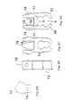
- FIG. 2Ashows a side view of the top cavity section removed from the body of the miniature vein enhancer of FIG. 1 .
- FIG. 2Bshows a side view of the body of the miniature vein enhancer of FIG. 1 .
- FIG. 2Cshows a side view of the body with the top cavity section removed.
- FIG. 2Dshows a side view of the body with the left and right wall pivoting about their respective pivot points.
- FIG. 2Eis a rear view of the body with the top cavity section in place.
- FIG. 2Fis a side view of the body of FIG. 2E .
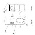
- FIGS. 3A to 3Fshow an alternative embodiment of the miniature vein enhancer of the present invention where the top cavity section is fixedly attached to the body.
- FIGS. 4A and 4Bshow an alternative vial holder used with the present invention.
- FIGS. 5A to 5Cshow an alternative mounting embodiment for an MVE.
- FIGS. 6A and 6Bshow an alternative embodiment of the MVE of the present invention.
- FIG. 7shows a still further embodiment of the MVE of the present invention that is particularly useful for accessing veins in the arms of patients.
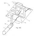
- FIG. 8shows an embodiment of the invention where the MVE is mounted on a base.
- FIG. 9shows an MVE on a base with a flexible “gooseneck” arm.
- FIG. 10shows an MVE with an alternative type of gooseneck.
- FIGS. 11A to 11Dshow the MVE of the present invention removably mounted to a phlebotomist's chair.
- FIGS. 12A-12Bshows a prior art vial holder.
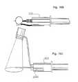
- FIG. 13Ashows an improved vial holder that has particular application to the present invention.
- FIG. 13Bis a side view of the MPH mounted to the improved vial holder depicted in FIG. 13A .
- FIG. 13Cis a top view of the MPH mounted to the improved vial holder depicted in FIG. 13A in a scale of 1:1.
- FIG. 13Dis a side view of the MPH mounted to the improved vial holder depicted in FIG. 13A in a scale of 1:1.
- FIG. 13Eis a front view of the MPH mounted to the improved vial holder depicted in FIG. 13A in a scale of 1:1.
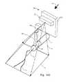
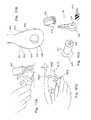
- FIGS. 14A to 14Bdepict an embodiment of the present invention in which the MVE is integrated into a magnifying glass housing.
- FIG. 14Cis a rear view of another embodiment of the present invention with a display used to view the image of the miniature vein enhancer.
- FIG. 14Dis a front view of the embodiment depicted in FIG. 14C .
- FIG. 14Eis a front view of the embodiment depicted in FIG. 14C with the miniature projection head located on the lower portion of the display.
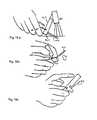
- FIGS. 15 a to 15 ddepict an embodiment of the present invention in which MVE has a disposable stand.
- FIGS. 16 a to 16 cdepict an embodiment of the present invention in which the MVE implements a different disposable type of stand.
- FIG. 17 ais a perspective view of the MVE attached to a disposable mounting bracket.
- FIG. 17 bis a perspective view of the ring portion of the mounting bracket of the MVE depicted in FIG. 17 a.
- FIG. 17 cis an exploded view of the MVE depicted in FIG. 17 a.
- FIG. 17 dis a side view of the MVE depicted in FIG. 17 a with a practitioner asserting a downward force.
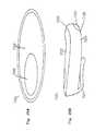
- FIG. 18 ais a perspective view of the MVE attached to a disposable mounting bracket having a support ring.
- FIG. 18 bis a perspective view of the ring portion of the mounting bracket of the MVE depicted in FIG. 18 a.
- FIG. 18 cis an exploded view of the MVE depicted in FIG. 18 a.
- FIG. 18 dis a side view of the MVE depicted in FIG. 18 a with a practitioner asserting a downward force.
- FIG. 19 ais a perspective view of the MVE attached to a disposable mounting bracket having a support ring that implements a support post.
- FIG. 19 bis a perspective view of the ring portion of the mounting bracket of the MVE depicted in FIG. 19 a.
- FIG. 19 cis a side view of the MVE depicted in FIG. 19 a with a practitioner asserting a downward force, after use, so as to cover the needle.
- FIG. 19 dis an exploded view of the MVE depicted in FIG. 19 a.
- FIG. 20a perspective view of the MVE attached to a disposable syringe.
- FIG. 20 bis a front view of the MVE depicted in FIG. 20 a.
- FIG. 21 ais a side view of the MVE with a MPH bracket and disposable shield.
- FIG. 21 bis a perspective view of the MPH depicted in FIG. 21 a.
- FIG. 22 ais an exploded view of the MVE with the MPH having a knurled cap for battery access.
- FIG. 22 bis a side view of the MVE depicted in FIG. 22 a in a hand held version.
- FIG. 22 cis a side view of the MVE depicted in FIG. 22 a with a screw on bezel.
- FIG. 22 dis front view of the holder of the MVE depicted in FIG. 22 a.
- FIG. 22 eis a side view of the MVE depicted in FIG. 22 a attached to the needle cover.
- FIG. 23 ais a side view of the MVE with a hexagonal body shape.
- FIG. 23 bis a front view of the holder of the MVE depicted in FIG. 23 a.
- FIG. 23 cis a side view of the MVE depicted in FIG. 23 a attached to the needle cover.
- FIG. 23 dis a side view of the MVE depicted in FIG. 23 a with a string attached.
- FIG. 24 ais a side view of the MVE attached to a flashlight.
- FIG. 24 bis a perspective view of the MPH of the MVE depicted in FIG. 24 a attached to a needle cover.
- FIG. 24 cis a side view of the MVE depicted in FIG. 24 a with the MPH detached from the flashlight.
- FIG. 24 dis a bottom view of the MVE depicted in FIG. 24 a with the MPH detached from the flashlight.
- FIG. 24 eis a side view of the MVE depicted in FIG. 24 a being held in a practitioners hand.
- FIG. 24 fis a bottom view of the MVE in a scale of 1:1.
- FIG. 24 gis a perspective view of the MVE in a scale of 1:1.
- FIG. 24 his a side view of the MVE in a scale of 1:1.
- FIG. 24 iis a front view of the MPH of the MVE in a scale of 1:1.
- FIG. 25 ais a top view of another embodiment of the MVE of the present invention.
- FIG. 25 bis a side view of the MVE depicted in FIG. 25 a.
- FIG. 25 cis a side view of the MVE depicted in FIG. 25 a attached to a vial.
- FIG. 25 dis a side view of the MVE depicted in FIG. 25 a being held in the hand of a practitioner.
- FIG. 25 eis a side view of the top portion of the needle cover of the MVE depicted in FIG. 25 a.
- FIG. 26 ais a perspective view of the MVE with a generally pear shaped battery holder.
- FIG. 26 bis a side view of the MVE depicted in FIG. 26 a mounted to a needle cover.
- FIG. 26 cis an exploded view of the MVE depicted in FIG. 26 a.
- FIG. 26 dis a perspective view of the MVE depicted in FIG. 26 a being held in the hand of a practitioner.
- FIG. 27 ais a perspective view of the MVE with a generally rectangular battery holder.
- FIG. 27 bis a side view of the MVE depicted in FIG. 27 a mounted to a needle cover.
- FIG. 27 cis a side view of the MVE depicted in FIG. 27 a with the MPH being slidably attached.
- FIG. 27 dis a side view of the MVE depicted in FIG. 27 e 34 a being held in the hand of a practitioner.
- FIGS. 28A and 28Brepresent the image of veins on the patient field of view.
- FIG. 29depicts a prior art scanning laser based camera.
- FIG. 30illustrates an example of the MPH of the present invention.
- FIG. 31shows a control block diagram for the MPH
- FIG. 32shows the Dual Buffer Mode of operation of the MPH.
- FIG. 33depicts the Real Time Mode of operation of the MPH.
- FIG. 1shows a miniature vein enhancer (MVE) 1 for enhancing a target area 4 of a patient's arm 3 .
- the MVE 1has miniature projection head (MPH) 2 for both imaging the target area 4 and for projecting an enhanced image 11 along optical path 5 onto the target area 4 .
- the MPHwill be described in detail later with reference to FIG. 18-FIG . 21 .
- the MPH 2is housed in a cavity section preferably a top cavity section 12 of the MVE 1 .
- the body 13 of the MVE 1is positioned below the top cavity section 12 .
- the body 13has a vial opening 8 for receiving and temporarily holding in place a vial holder 7 having a needle 14 .
- the body 13also has a thumb opening 9 through which the medical practitioner 6 can place their thumb 10 while utilizing the MVE 1 .
- the vial opening 8is preferably provided with at least a curved base section 8 A for receiving the curved exterior surface of the vial holder 7 and retaining it in position.
- the thumb opening 9may be a separate orifice or it may be part of the vial opening 8 .
- MVE 1The functioning of the MVE 1 of FIG. 1 follows.
- a medical practitioner 6places a standard vial holder 7 into the vial opening 8 .
- the vial opening 8is shaped such that it snuggly holds the vial holder 7 in place.
- MVE 1is preferably battery operated and is turned on by the practitioner 6 via an on/off switch not shown. Alternatively the unit can be turned on/off by a switch which detects the presence of the vial holder 7 in vial opening 8 .
- the practitioner 6places his thumb 10 though the thumb opening 9 and supports the bottom of the vial holder 7 with his forefinger. This mimics the normal grip that many practitioners use when grasping a vial holder for insertion into the veins of the patient.
- the MPH 2takes an image of the of the patient's 3 veins 11 within the target area 4 . After receiving the image, the MPH projects along the optical path 5 onto the target area 4 a visible image of the veins.
- the portable size of the MVEprovides many advantages over the prior art units.
- the prior art unitsare too large to be held with a single hand, and in fact are fix mounted or mounted on rolling carts.
- This present inventionis small enough to be portably carried by mobile workers, such as, doctors, nurses, emergency health workers, military personnel, police, and visiting home phlebotomists.
- the portable MVEcan be moved quickly over the patient body thereby viewing a large number of veins in a short period of time. Further, the single handed operation of the MVE frees up the second hand of the care giver for other purposes.
- FIG. 2A-2Fillustrates in further detail the MVE 1 of FIG. 1 .
- FIG. 2Ashows the top cavity section 12 disconnected from the body 13 .
- At least one but preferably two holes 15 for removably mounting the top cavity section 12 to the body 13are situated on each side of the top cavity section 12 .
- FIGS. 2B and 2Cshow the body from two different perspectives.
- the bodyhas a protrusion 16 which are shaped to fit into the holes 15 on the top cavity section 12 , thereby facilitating removable attachment of the body 13 to the top cavity section 12 .
- the orifices 15could be in the body 13 and the protrusions 16 in the top cavity section 12 .
- FIGS. 1illustrates in further detail the MVE 1 of FIG. 1 .
- FIG. 2Ashows the top cavity section 12 disconnected from the body 13 .
- At least one but preferably two holes 15 for removably mounting the top cavity section 12 to the body 13are situated on each side of the top cavity section 12 .
- FIGS. 2C and 2Dshow the body 13 with the top cavity section 12 removed.
- a cross member 18connects to the left wall 20 and right wail 21 at pivot points 17 .
- release buttons 19are squeezed together the bottoms of the left 20 and right walls 21 move apart increasing the size of the vial opening 8 , thereby releasing a pressure hold on the vial holder 7 (not shown).
- the top cavity 12applies an outward force at the tops of the left wall 20 and right wall 21 thereby reducing the size of the vial opening 8 , thereby insuring a snug connection between the vial holder 7 and the body 13 .
- inward pressure on the left wall 20 and right wall 21 at the bottom thereofapplies an outward force at the tops of the left wall 20 and right wall 21 permitting easy insertion of the top cavity section 12 between the left and right wall on the body.
- FIG. 2Eis a rear view of the body 13
- FIG. 2Eis a side view of the body 13
- the removable top cavity section 12snaps into place in the body 13 and is held in place by protrusions 16 which insert into the holes 15 (not shown in FIGS. 2E and 2F ).
- the protrusions 16disengage from the holes 15 when the left 20 and right walls 21 are pressed towards each other.
- FIG. 3A-3Fshows another embodiment of the present invention.
- FIGS. 3A-3Falso shows an illustrative sequence of using the MVE.
- the MVE 1is similar to that of FIG. 2A-2F except that it has a top cavity section 12 which is fixedly attached to the body 13 .
- the bottom portion of the body 13has two sides 30 and 31 extending downward with an opening on the bottom for receiving the vial holder 7 .
- the two sides 30 and 31are normally biased so as to farm a tight friction fit around the vial holder 7 , but the vial holder can be loosened by depressing simultaneously at points on the body under the thumb and index finger of the practitioner's left hand as shown in FIG. 3A to allow easy attachment between the vial holder 7 and the MVE 1 .
- the first step of operationis shown in FIG. 3A wherein the practitioner 6 holds the body 13 of the MVE 1 and squeezes (between the thumb and index finger) to release the bias of the two sides 30 and 31 .
- the practitioner 6then takes a new vial holder 7 , positions it in between the two sides 30 and 31 and releases the pressure between the thumb and index finger thereby allowing the sides to move towards their normally biased position around the vial holder 7 .
- the MVE 1is now removably attached to the vial holder 7 .
- the thumb and index fingermay squeeze the vial holder 7 to release it from the body.
- FIG. 3Bshows the second step of operation is shown in FIG. 3B wherein the practitioner activates the MPH 2 (not shown in these figures) contained within the head of the top cavity section 12 .
- FIG. 3Bshows this activation being performed by depressing a button 32 on the top of the MVE 1 , or alternatively, the unit can automatically initiate when the MVE is attached to the vial holder 7 .
- FIG. 3Cshows the practitioner 6 approaching the arm of a patient 3 with the MVE 1 .
- the optical path 5 and the field of view 4 of the MVE 1are shown in FIG. 3C .
- the veins 11 of the patients 3 armare visually projected from the MPH 2 onto the patients arm.
- a significant advantage of the MPH 2 used in a handheld configurationis the fact that the image at the field of view 4 is always in focus, regardless of the distance from the MPH 2 to the patient 3 . Since the distance between the MPH 2 and the patient is constantly decreasing as the MVE 1 approaches the patient 3 , the prior art systems, which have limited fields of view, would not work property in such an embodiment. It should be further noted that the practitioner only needs at this time to utilize one hand to manipulate the vial holder 7 as well as support the MVE 1 . This leaves available the second hand for other tasks.
- the point of the needle 14is within the optical path 5 of the MPH 2 . Accordingly, the practitioner can move the MVE 1 over the patient's arm 3 viewing the entire vein structure of the patient. When the practitioner wants to approach a particular vein with the needle 14 , the vein remains within the field of view even as the needle is brought down the surface of the patient.
- the prior art systemshad imagers and projectors which were fixedly mounted, and therefore to view large areas of the patients body either the entire projector had to be move relative to the patient, or the patient had to be moved relative to the projector.
- FIG. 3Dshow the practitioner inserting the needle 14 of the MVE 1 into the patient's vein 11 . It should be noted that throughout steps 3 C and 3 D only a single hand of the practitioner is required.
- FIG. 3Eshows the practitioner 6 initiating removal of the MVE 1 from the vial holder 7 by squeezing between his thumb and index finger the top portions of side walls 30 and 31 , thereby reducing the pressure upon the vial holder 7 .
- FIG. 3Fshows the MVE 1 being removed from the vial holder 7 .
- the MVE 1can then be set aside for future use.
- the practitioner at this pointcan perform all task normally performed after the vial holder is inserted into a patient's veins.
- FIGS. 3A-3Futilized a standard cylindrical vial holder 7 and relied on pressure between the side arms 30 and 31 to hold the vial holder in place. Accordingly existing standard vial holders 7 can be utilized. It will be appreciated by those skilled in the art that vial holders having a different cross section than cylindrical can also be used by modifying the inside surface of the side arms.
- FIG. 4Aillustrates a top view such a new vial holder 40 and the side arms 42 and 44 of a MVE.
- the vial holder 40has four indentations 41 , two on one side of the cylindrical body and two directly opposite.
- the side arms 42 and 44 of the MVEhave four protrusions 43 that are slightly smaller in size than the indentations 41 .
- the side arms 47 and 48can be curved to form the rounded vial opening 8 of FIG. 1 .
- the armsare configured with indentations 45 , two on each side arm, which are positioned to receive protrusions 46 which are incorporated into the vial holder 40 of this embodiment. Accordingly, when a vial holder with protrusions as shown in FIG. 4B is utilized, the locking mechanism between the MVE and the vial is strong due to the mating of the protrusions 46 and the indentations 45 .
- an existing vial holder 7 shown in FIG. 1is used (without the protrusions), the unit will function as described in FIG.
- the an MVE having the side arms shown in this FIG. 4Bcan be utilized with existing vial holders or can be use with the new vial holder shown in FIG. 4B .
- FIGS. 4A and 4Billustrates mounting arrangements between vial holders and a MVE
- the present inventionis not limited thereto.
- Many other types of removable mounting arrangementscan be considered, such as, for example, the detachable mounting arrangement utilized between razors and razor blades.
- Manufactures of the MVE which utilize the new vial holder of FIG. 4A and FIG. 4Bwill be able to sell a system which contains a single MVE as well as multiple disposable vial holders 40 . Further, a consumable business for disposable vial holders as shown in FIGS. 4A and 4B can be established.
- FIG. 5A-FIG . 5 Cshows various views of an alternative mounting embodiment for an MVE.
- the MVE 50is connected to a strap 51 .
- the MVE 50may be connected to a mounting plate 52 which in turn is strapped with strap 51 to the back of the hand of the practitioner 6 .
- the MVE 50is rotatably mounted on the mounting plate 52 .
- the connection rotatable between the MVE 50 and the mounting plate 52allows the MVE 50 to be rotated about a first axis 53 perpendicular to the back surface of the users hand and also rotate about a second axis 54 horizontal to the hand.
- the MPH 2(not shown) is housed within the MVE and projects along optical path 5 to field of view 4 (in the same manner as described earlier with reference to FIG. 1 ).
- the practitionercan aim the optical path 5 so that the field of view 4 is positioned around the point of the needle 14 .
- FIG. 5Bshows a top view of the MVE 50 of this embodiment.
- FIG. 5Cshows the bottom of the practitioners 6 hand.
- the strap 51can be attached by Velcro 55 or other suitable means to enable the practitioner to easily attach and detach the MVE 50 .
- FIG. 6Ashows yet another alternative mounting embodiment for an MVE.
- the MATE 60is connected to strap 61 which goes around the head of the practitioner 6 .
- the MPH 2(not shown) is housed within, the MVE 60 and projects along optical path 5 to field of view 4 (in the same manner as described earlier with reference to FIG. 1 ).
- the practitioner 6can easily move the optical path 5 by moving his head, thereby placing the field of view 4 anywhere desired on the patient.
- the MVE 60is positioned so that the optical path 5 substantially corresponds with the line of site of the practitioner 6 when looking forward, the placement of the field of view 4 on the patient will be very natural to the practitioner 4 .
- the strap 61can be attached by Velcro (not shown) or other suitable means to enable the practitioner to easily attach and detach the MVE 60 .
- FIG. 6Bshows in more detail the MVE 60 of FIG. 6A .
- the MPH 2(not shown) is housed in an adjustable housing 62 which is movably connected to a base 63 .
- the relationship between the adjustable housing 62 and the base 63may be that of a ball and socket.
- the adjustable housing 62is preferably round and the base 63 is a corresponding concave socket.
- the practitionercan rotate the adjustable housing 62 within the base 63 to change the direction of the optical path 5 relative to the head of the practitioner. In this manner, the mounting of the MVE 60 to the head can be less precise, and optimization of the direction of the optical path 5 is adjusted by moving the adjustable housing 62 within the base 63 .
- This embodimentleaves both hands of the practitioner completely unencumbered while allowing the field of view 4 of the image on the patent to be easily moved by simple head movements of the practitioner.
- FIG. 7shows yet another embodiment of the MVE which is particularly well suited for accessing the veins in the arm of a patient 3 .
- tourniquetsare often placed around the bicep of the arm so as to enlarge the veins of the arm and make them easier to insert needles into.
- the MVE 70is mounted onto a tourniquet 71 which gets placed around the bicep of the patient 3 .
- the tourniquet 71can be tightened around the bicep and held tight by e.g., Velcro scraps 72 .
- the MVE 70is oriented such that the optical path 5 from the MPH (not shown) housed within the MVE 70 is directed towards the target veins 73 on the arm. In this manner, the MVE is held in place and the Practitioner 6 has both hands available for use.
- FIG. 8shows another embodiment of the MVE.
- the MVE 80is mounted on a generally clear plastic or glass base 81 which can be placed by the practitioner 6 on the arm of the patient 3 .
- the base 81has a curved bottom 82 which conforms roughly to the shape of the arm of the patient 6 .
- the basemay be provided with openings on sides 83 and 84 near the area where the base contact the patient's arm to receive a strap or other means to secure the MVE to the arm without unnecessarily blocking the view of the veins.
- the MPH(not shown) is housed within the MVE 80 and is oriented so that the optical path is downward from the MVE to the arm resulting in the field of view 4 falling on the patient's arm.
- the curved bottom 82is also curved concavely inwards so as to provide unobstructed access to the veins of the patient with needle 14 .
- the base 81needs to be relatively transparent to permit the visual image of the veins projected from the MPH (not shown) within the MVE 80 to pass from the arm of the patient 6 through the base 81 to the viewer.
- One advantage of this embodimentis that, because the MVE 80 is portable, it can be quickly positioned on patient's arm 3 , and can quickly be removed after use and placed on the side while the practitioner 6 continues their work.
- FIG. 9shows an embodiment of the MVE wherein the MVE 90 is mounted on an adjustable arm 92 which connects on one end to the MVE 90 and at the other end to a base 91 .
- the arm 92 in this embodimentis shown as a gooseneck type arm, however other arrangements are possible.
- the baseis shaped so that it can comfortably support the patient's 3 arm.
- the gooseneck arm 92is such it can be moved and rotated by the practitioner 6 , but after such movement or rotation, it maintains its set position.
- Gooseneck type armsare well known in the art and need not be described further herein.
- the MPH 2(not shown) is housed within the MVE 90 and projects along optical path 5 to field of view 4 . The operation of FIG. 9 will now be described.
- the patient 3places their arm on the base 91 with the elbow facing down.
- the practitioner 6turns on the MVE 90 via a switch (not shown).
- the MVE 90can turn on automatically when a pressure sensor (not shown) in the base 91 detects the presence of an arm positioned thereon.
- the practitioner 6then moves and rotates the MVE 90 until the field of view 4 falls on the desired veins 11 , the field of view 4 remains in a fixed position upon the patient's arm.
- the practitionermay then release the MVE 90 , and then go about accessing the vein 11 .
- FIG. 10shows an embodiment that is similar to that of FIG. 9 except that the supporting mechanism 101 is much wider and can support a larger weight.
- the MPHis housed in the MVE 100 at a position so that the optical path of the MPH exits through an opening 103 .
- the embodiment of FIG. 10includes a touch display 102 , through which the practitioner can adjust parameters of the MPH (not shown), such as for example, the brightness, contrast and the projection angle of the MPH.
- FIGS. 11A-11Dshow an embodiment wherein the MVE 111 removably mounts to an existing phlebotomist's chair 110 having a armrest 112 upon which a patient can rest their arm while the practitioner is accessing their vein.
- the MPH(not shown) is mounted in the top portion 113 and projects along optical path 5 to field of view 4 which is positioned on the armrest 112 .
- the top portion 113mounts to bottom portion 114 in such a manner that the top portion 113 can slide up and down relative to the bottom portion 114 , thereby increasing and decreasing the distance from the MPH to the armrest 112 .
- the field of view 4grows larger but the brightness at a given location within the field of view 4 decreases.
- the field of view 4shrinks but the brightness at a given location within the field of view 4 increases.
- FIGS. 11C and 11Dshow in greater detail an example of how the MVE 111 can be attached to the armrest 112 of the chair 110 .
- the bottom portionhas a “C” like structure 115 that can be placed over the armrest 112 .
- a screw mechanism 116can be turned to attach the MVE 111 to the armrest 112 .
- One skilled in the artwill appreciate that there are other types of means for securing the MVE 111 to the armrest 112 .
- FIG. 12Bshows a prior art vial holder 123 with a prior art needle protector 120 connected.
- the needle protectorhas a main body 121 and a circular mounting ring 122 which fits directly over the front of the prior art vial holder 123 .
- FIG. 12Ashows the prior art needle protector 120 disconnected from the vial holder 123 .
- FIGS. 13A-13Eshows a needle holder 125 in accordance with the present invention that is capable of supporting a MVE.
- the needle holder 125has a main body 126 and a circular mounting ring 127 which fits directly over the front of a prior art vial holder 123 . Additionally, the needle holder also has a thumb support 128 at the base of the needle holder 125 .
- FIG. 13Bshows the needle holder 125 of FIG. 13A connected to a prior art vial holder 123 and a MVE 131 temporarily connected to the needle holder 125 .
- a MVE 131has a main body portion 130 which houses the MPH 2 .
- the main body portion 130is rotationally connected to a stem portion 129 in such a manner that the main body portion 130 can be rotated by a practitioner thereby rotating the optical path 5 up or down.
- the connection between the stem portion 129 and the main body portion 130is stiff enough that after the practitioner moves main body portion 130 up or down, it remains in that position even after the practitioner releases the main body portion 130 .
- the stem portion 129 of the MVE 131has an opening at the bottom that is shaped to receive the top of the main body 126 of the needle protector 125 .
- the locking mechanismis designed so that stem portion 129 can rotate while snapped to the top of the main body 126 .
- the fitting between the twois tight enough so that after the stem portion 129 is rotated by the practitioner, no further rotation occurs unless and until the practitioner again rotates the stem portion 129 .
- a thumb support 128is in contact with the vial holder 123 .
- a practitionerwould position their thumb on top of the thumb support 128 and their index finger on the opposite side of the vial (across from the thumb support). In this manner, the practitioner is supporting in a single hand the vial holder 123 , the needle protector 125 and the MVE 131 .
- the practitionercan move the main body portion 130 of the MVE so that the optical path 5 is aligned so that the field of view includes the point of the needle.
- the MVE 131can be detached from the needle protector and placed down on a surface. At this point in the process, the blood can be withdrawn in the same manner as the prior art system of FIG. 12B . Upon completion of activity, the vial holder 123 and the needle protector 125 can be disposed of.
- FIGS. 14A and 14Bshow an embodiment wherein the MPH 2 is integrated into a magnifying glass housing 143 which supports a magnifying glass 140 .
- the magnifying glass housing 143connects, for example via a gooseneck or other type support 141 to a clamp 144 which in turn can mount to a table, the arm of a phlebotomist chair or other suitable support.
- the MPH 2is positioned within the magnifying glass housing 143 such that the optical path 5 is aimed downward towards the table or arm of the chair. When a patient 3 places their arm on the table the field of view 4 falls upon the arm. As shown in FIG.
- the magnifying glass 142 of FIGS. 14A and 14Bcan be replaced with a flat panel display.
- the MPH 2only has to capture the image of the veins and the needle of the vial holder 142 within the field of view 4 and does not have to retransmit a visible image onto the arm. Instead, the visible image of the veins and the needle is transmitted onto the flat panel display 142 which is viewed by the practitioner as he inserts the needle into the vein.
- the practitioneris not directly viewing the needle or the arm but instead is viewing an image thereof in the flat panel display 142 .
- the image in the flat panelcan digitally be enlarged or reduced (zooming) as required by the practitioner.
- the controls for such zoomingcan be via touch screen input onto the flat panel display.
- FIGS. 14C and 14Dshow two perspectives of yet another embodiment of an MVE 150 .
- the MVE 150includes a small display 151 , which is viewed along viewing angle 157 by the practitioner, having attached thereto an attachment piece 154 and a MPH 2 .
- the attachmentis shown at a right angle to the stem extending vertically from the vial, the stem can be at an angle to the vial and the display angle can vary, as well.
- a needle protector 156similar to that shown in detail in FIG. 13A connects to a vial holder 7 .
- the attachment piece 154receives the top of the needle protector and temporarily locks the MVE to the needle protector 156 which in turn attaches to the vial holder 7 .
- the MPH 2is attached to the small display 151 and is oriented so that the optical path 5 is such that the field of view 4 covers the point of the needle 14 .
- the MPH 2outputs the image of the veins 11 onto the field of view 4 on the patient (not shown).
- the MPH 2also provides the image signal to the display 151 to be viewed on the display 151 .
- the image signalincludes both the veins and the needle 14 .
- the display 151includes image processing capabilities that detects the position of the tip of the needle and displays a predetermined number of pixels of the image around the tip of the needle on the display. In FIG. 14C , both the image of the needle 153 and the image of the vein 152 are shown.
- An example of using the MVE 150 of FIG. 14Cfollows. A practitioner selects a disposable sterile vial holder 155 which has the needle protector 156 attached thereto. The needle protector 156 is moved to right angle position relative to the needle 14 , thereby exposing the needle. The MVE 150 is connected via the attachment piece 154 to the top of the needle protector 156 . The MVE is then turned on and the MPH 2 receives the image of the veins 11 and the needle 14 within the field of view 4 . The practitioner would move the MVE 150 about the patient viewing the image of the veins 11 projected onto the patient. The image of the veins will be the actual size and position of the patient's veins.
- the practitionerWhen a vein is selected for puncture with the needle, the practitioner will bring the needle towards the vein while still viewing the image of the veins on the patient body. When the practitioner gets close to the selected vein with the point of the needle, the practitioner will look at the display 151 image which is an enlarged image of the point of the needle 153 and the target vein 152 . By using this enlarged image, the practitioner can be certain to puncture the center of the vein 11 with the needle 14 .
- the display 151can be very small given that all it has to do is show the amplified view of a single vein and the needle.
- FIGS. 28A and 28Bwherein FIG. 28A represents the image of the veins 11 on the patient in the field of view 4 , and FIG. 28B represents the image of the vein 152 and the image of the needle 153 displayed on the display 151 .
- the target veinis 0.10 inch across and the field of view 4 is 3′′ by 3′′
- the resolution of the image captured and projected by the MPH 2 in the field of viewis 1000 pixels by 1000 pixels.
- the MVEis programmed to display on the display 151 a 300 pixel by 300 pixel area having the needle centered therein.
- the resulting amplified image of the vein 152is shown at more than three times its original width.
- the amount of magnification (zoom amount) on the display 151can be algorithmically adjusted by a processor in the display. Inputs can be provided for the practitioner to select the appropriate gain amount.
- FIG. 14EAn alternative embodiment is shown in FIG. 14E wherein the display 151 of FIGS. 14C and 14D is replaced by a rear projection screen 158 .
- the MPHcan be configured to project a split image. The bottom half is the actual image representing the veins 11 and the top half is an image of the magnified image of the veins and needle.
- a mirror 159is placed within the optical path 5 of the top half of the image projected by the MPH 2 . The mirror 159 is angle so that the top half of the image is projected along optical path 5 B to the rear projection screen 158 .
- Rear projection screenis translucent and can be viewed by the practitioner along viewing angle 157 . In this manner, a display screen is obtained without incurring the addition cost, size and power of the dedicated display of FIG. 14C and FIG. 14D .
- the MVEmay have a disposable stand 200 , which may include a generally “C” shaped base clip portion 201 .
- Base 201may be constructed from the same materials as the previously mentioned embodiments.
- MVE stand 200can be molded from a clear plastic. Any suitable clear plastic known in the art including but not limited to PVC, Polystyrene, Acrylic and the like may be used.
- Extending from base 201may be an arm 202 , which has a concave bottom corner 203 and a convex top corner 204 . Both corners may be integrally formed with base 201 .
- Arm 202may have an inside surface 205 and an outside surface 206 .
- a second generally “C” shaped clip 209Located between top corner 204 and bottom corner 203 of arm 202 may be a second generally “C” shaped clip 209 .
- Located at the top of MVE 200may be a generally circular ring portion 207 .
- Ring portion 207may be an integral member of MVE stand 200 or ring 207 may be a separately attached member. In a preferred embodiment ring 207 was integrally formed with stand 200 .
- ring 207may have a generally circular threaded outer top surface, so as to act as a male end, or ring 207 may have a generally circular grooved inner surface, so as to act as a female end, a utility of which will now be discussed.
- MPH 208will operate as in the previous discussed embodiments, however in the present embodiment MPH 208 may have either a threaded outside surface or a grooved inside surface, this will be a matter of preference. For example, if ring 207 has a threaded outside surface MPH 208 will have a corresponding grooved inside surface, this will give the practitioner the ability to attach and remove the MPH, before and after use, respectively. In normal operation the practitioner will snap clip 201 to prior art vial 220 . In addition, the practitioner will snap clip 209 to prior art needle protector 221 . After the clips 201 and 209 have been attached the practitioner may then attach MPH 208 to ring 207 . This will be accomplished via the two previous attachment methods already discussed. It should be pointed out that the practitioner may also attach MPH 208 to ring 207 before attaching the rings to the vial.
- the practitionermay then continue with the procedure as previously discussed. After the procedure is complete the practitioner will then apply a pressure to surface 206 sufficient enough to push needle protector 221 and arm 202 over the used needle 223 , after which the MPH may be removed for future use and the needle and MVE stand 200 may be discarded.
- FIGS. 16 a - 16 cAnother embodiment of a disposable MVE stand 302 may be seen in FIGS. 16 a - 16 c .
- This type of embodimentmay include a MPH 301 , a stand 302 and a vial 303 .
- MPH 301may have the same operable features as previous mentioned MPHs.
- Stand 302may be constructed of any suitable known material in the art including but not limited to metal, metal alloy, plastic, plastic composite, or the like. In a preferred embodiment stand 302 can be made of plastic. Plastic was preferred because of cost effectiveness and sanitary qualities.
- MPH 301may operate as in the other previous mentioned embodiments, however unique to the present embodiment are carriages 304 and 304 a located on MPH 301 and vial 303 , respectively.
- Carriage 304may be any suitable shape known in the art, in a preferred embodiment carriage 304 has a generally rectangular shape.
- carriage 304may have an orifice 307 extending from a front end 305 to a rear end 306 , or partially therethrough. In a preferred embodiment orifice 307 does not extend the entire length of carriage 304 , as seen in FIG. 23 a .
- Orifice 307may have a diameter that is slightly smaller than holder portion 309 of stand 302 .
- Stand 302may have also have a keeper portion 310 . It should be pointed out that keeper 310 and holder 309 , as seen in FIGS. 23 b and 23 c , are generally the same shape and size as each other and in the preferred embodiment may be used interchangeably.
- carriage 304 aLocated on at least one side of vial 303 may be another carriage 304 a , as mentioned above.
- carriage 304 amay be generally the same size and shape as carriage 304 . However, one may implement different sizes and shapes for any of the carriages and/or arms.
- Carriage 304 amay also have an orifice 307 a that extends from a front end 305 a to rear end 306 a , as in carriage 304 . In the preferred embodiment both carriages have orifices that extend equally the same length.
- carriage 304 and 304 ais that carriage 304 is slightly rounded, so as to conform to MPH 301 .
- MPHmay have a straight base, in which case carriage 304 may not be rounded.
- Carriages 304 and 304 amay be located anywhere on MPH 301 and vial 303 , respectively.
- the practitionermay insert holder arm 309 into orifice 307 and keeper arm 310 into orifice 307 a . Once inserted the practitioner may move the MVE to the desired position. Since the individual carriage orifices have smaller diameters than the respective arms that they receive, the relied upon pressure will keep the MPH from moving during the procedure.
- FIGS. 17 a - 17 dis another embodiment of the present invention.
- the MPH 401operates in generally the same manner as the previous mentioned embodiments.
- a unique feature of this embodimentis the mounting bracket 400 , which acts as a needle cover too.
- Mounting bracket 400may included a mast portion 402 and a ring portion 403 that is hinged to mast 402 .
- Ring portion 403may be generally circular in shape with a front surface 404 and a rear surface 405 .
- ring portion 403may have an orifice 406 that may extend from front surface 404 to rear surface 405 , as seen in FIGS. 24 a - 24 c.
- Orifice 406may be defined by inner circumferential wall 407 . Orifice 406 of ring 403 may be sized to receive neck 408 of vial holder 409 . In addition orifice 406 should have a diameter that will allow ring 403 to snap onto neck 408 of vial 409 , this will allow the practitioner to attach bracket 400 before the procedure and dispose of bracket 400 after the procedure is performed, i.e. a disposable bracket.
- Ring 403may also have a generally flat top surface 410 .
- Flat top surface 410may includes a break-away support diaphragm 411 that provides fore and aft stability, as seen in FIG. 17 b .
- Also located on top surface 410may be a living hinge 412 , which provides side to side stability.
- Hinge 412may be any suitable type of hinge known in the art, in the preferred embodiment there can be a flexible plastic strip that connects ring 403 to mast 402 .
- located on top surface 410may be a locking mechanism that keeps mast 402 in an upright position when the practitioner is inserting the needle into the patient's arm and thereafter when the practitioner is drawing blood from the patient.
- mast 402may also act as a needle cover, and as such should be shaped and sized so as to be able to completely cover the needle 413 before and after use.
- mast 402should be sized and shaped to be able to snuggly receive a bottom portion 414 of MPH 401 .
- Mast 402 and ring 403may be integrally formed or separately attached members. In the preferred embodiment mast 402 and ring 403 were integrally formed.
- support ring 420used for stabilizing mast 402 and MPH 401 , as seen in FIGS. 18 a - 18 b .
- support ring 420may be defined as semi-circular, with a right arm 421 and a left arm 422 extending from a top area.
- Support ring 420may also have an outer surface 423 that may extend from right arm 421 to left arm 422 , and a inner surface 424 that also may extend from right arm 421 to left arm 422 , as seen in FIG. 18 c .
- Located on inner surface 424 of arms 421 and 422may be two detents, 425 and 426 respectively.
- Detents 425 and 426may be generally circular in shape and may extend from inner surface 424 to outer surface 425 , so as to form two orifices, as in the present invention. Conversely, detents 425 and 426 may only extend partially into inner surface 424 , so as to form two bored cavities.
- MVEmay also have a mast 427 and a ring 428 , which may, as in a preferred embodiment, or may not be hinged to mast 427 .
- support ring 420pivotally attaches to mast 427 , this may be achieved via two generally circular dimples 429 and 430 located on the outside surface 431 of mast 427 .
- Detents 425 and 426 and dimples 429 and 430may be centrally aligned along the same axis of rotation so as to allow for pivotal movement of mast 427 . In normal operation the practitioner will snap on support ring 420 to neck 433 , as in the previously discussed embodiment.
- the practitionermay then attach ring portion 428 to neck 433 , after which, dimples 429 and 430 may be inserted into detents 425 and 426 .
- MPH 401may then be connected to mast 427 . Once all members are attached the practitioner may then operate the MVE as in all previous embodiments.
- vial 460may have two generally cylindrical pegs, right peg 462 and left peg 463 , located on its upper front surface just above neck 461 .
- Peg 462may have an outer and inner surface, 462 a and 462 b , respectively.
- Peg 463may also have an outer and inner surface, 463 a and 463 b , respectively.
- Peg 462may have an orifice 462 c that extends from inner surface 462 a to outer surface 462 b , or orifice 462 c may extend only partially into peg 462 .
- Peg 463may have a similar orifice.
- mast 464may have a broader top portion 464 a and a narrower bottom portion 464 b .
- Top portion 464 amay be generally the same size and shape as the previous mentioned embodiments, and as in all other embodiments top portion 464 a has a slit that has a length equal to or greater than needle 413 .
- a key feature of mast 464is the generally cylindrical bottom member 464 b .
- Located on the outer side surfaces of bottom portion 464 bmay be two dimples, 464 c and 464 d , which extend outwardly in a generally perpendicular direction.
- the present embodimentmay also implement a support ring 465 , as in the previously discussed embodiments, which may be used to stabilize mast 464 and MPH 467 .
- Support ring 465may be generally circular in shape with a diameter that is slightly larger than neck 461 . This arrangement will allow for a snug fit and still allow support ring 465 to rotate a locked and unlocked position, as seen in FIG. 19 b .
- support ring 465may have at least one side bar 465 b extending perpendicular from generally outer circumferential surface 465 a .
- the preferred embodimentmay have a support post 465 d .
- Support post 465 dmay extend outwardly, preferably perpendicularly from outer surface 465 a and may be located near the top of ring 465 .
- Support post 465 dmay have a width that is equal to, less than, or greater than mast 464 preference.
- support post 465Located on the top portion of support post 465 may be platform 465 e used to maintain mast 464 in an upright position.
- Support post 465may have a length so as to allow support post 465 to fit snuggly under bottom surface 464 f .
- the practitionermay attach mast 464 to vial 460 . Once mast 464 is attached, support ring 465 may then be snapped onto neck 461 of vial 460 . At which time MPH may then be attached to mast 464 and support post 465 e placed in a locked position. After the practitioner is finished performing the venous puncture procedure, the practitioner may then rotate support ring 465 to an unlocked position and place mast 464 over needle 413 .
- the MVE 500may include a needle protector 501 , a mounting bracket 502 , a needle 503 and a MPH 504 .
- Needle cover 501may be sized and shaped as in the other previous discussed embodiments. One key distinction however, is the placement of needle cover 501 .
- needle cover 501may be placed on either the right or left side of vial 506 .
- needle cover 501is located on the right side of vial 506 , as seen in FIGS. 20 a - 20 b .
- Needle cover 501may have also have a bottom ring member 520 that is hinged to a top member 521 . Ring 520 may have a diameter so as to allow the practitioner to press fit the needle protector over neck 507 of vial 506 . Ring 520 may be hinged to top member as in the previous mentioned embodiments.
- Mounting bracket 502may be constructed of any suitable material known in the art including, but not limited to metal, metal alloy and the like. In the preferred embodiment mounting bracket 502 was constructed from medium strength plastic. Mounting bracket 502 may be defined as having a top surface 508 and a bottom surface 509 connected by a generally circumferential sidewall 510 , as seen in FIG. 20 a . Mounting bracket 502 may have a generally “C” shape, with two orifices 513 and 514 located near a front end 511 and a rear end 512 respectively. Orifice 513 is generally circular in shape having a diameter sized so as to be able to receive a portion of MPH 504 .
- inner circumferential wall 515may be designed so that MPH 504 may be secured to mounting bracket 502 by a press fit, or in another embodiment orifice 513 may have a threaded inner circumferential wall 515 so that a portion of MPH may be screwed to inner circumferential wall 515 .
- Orifice 514may be sized and shaped so as to be able to receive neck 507 of vial 506 .
- Mounting bracket 502may be press fitted to neck 507 . This press fit allows the practitioner to rotate mounting bracket 502 30 degrees to the left or right, thus, if the practitioner should encounter any visual obstructions during the venous penetration and/or extraction, the practitioner may simply rotate mounting bracket 502 .
- mounting bracket 502may be integrally formed with vial 506 , as in the preferred embodiment.
- mounting bracketmay be designed to rotate in a similar manner as in the press fitted mounting bracket.
- the practitionermay snap MPH 504 into orifice 515 . Once MPH 504 is securely attached the practitioner may then rotate mounting bracket 502 up to 30° left or right, if needed.
- the practitionermay attach needle cover 501 to neck 507 . After the practitioner has performed the venous penetration and/or extraction, the practitioner may then place needle cover 501 over needle 503 , remove MPH 504 from mounting bracket 502 and then dispose of syringe,
- the MVEmay include a MPH 550 , bracket 560 and vial 570 , as seen in FIG. 21 a .
- MPH 550may have a mounting groove 551 .
- Mounting groove 551may be any suitable shape known in the art including but not limited to a square, rectangle and the like. In the preferred embodiment a generally rectangular groove was implemented. One could also have a mounting bracket with more then one groove. For example there can be two rectangular grooves.
- Mounting bracket 560may be integrally formed with vial 570 or mounting bracket 560 may be a separately attached member. In a preferred embodiment, the mounting bracket was press fitted, which allowed the practitioner to dispose of the syringe after use.
- mounting bracket 560may be screwed on, and in another embodiment mounting bracket 560 may be bonded to vial 570 , via any suitable bonding method known in the art.
- Mounting bracket 560may have a generally upside down “L” shape, when looking at it from a side view, that is bent toward the bottom, as seen in FIG. 21 b .
- Located near the top of bracket 560may be two bracket fingers, left finger 561 and right finger 562 .
- Fingers 561 and 562have a generally “C” shape, when looking at them from the front, top, or bottom view. Fingers 561 and 562 are separated by a distance that will allow MPH 550 to be securely snapped into place.
- Mounting bracket 560may also have front and rear surfaces, 563 and 564 respectively, connected by right and left sidewalls 565 and 566 respectively. Located on surface 563 may be groove 563 a . Groove 563 a may extend from right sidewall 565 to left sidewall 566 , or partially therethrough. Groove 563 a may be used to secure an optionally removable disposable shield.
- the needle 571 and needle cover 572may be similar to the needle cover and needle of previous discussed embodiments.
- FIGS. 22-27Other embodiments of the present invention include hand held versions as seen in FIGS. 22-27 .
- the MPHwill operate in similar fashion as previously discussed.
- the first battery sourcemay act as a charger for the second battery source, when connected, thus allowing the practitioner to remove and use the MPH from the main body when desired.
- the needle coverwill also operate in similar fashion as previously discussed.
- FIGS. 22 a - 22 eThe main distinctions between the previous discussed embodiments and the embodiments of FIGS. 22-27 are the mounting techniques and/or added attachments.
- body 602 of MPH 600may be constructed of any suitable material in the art including but not limited to metal, plastic and the like.
- body 602can be made of a thermoplastic rubber.
- holder 604there can be a holder 604 that fits on needle cover 603 .
- Holder 604may be constructed of any suitable material known in the art, in the present invention holder 604 was constructed of plastic.
- holder 604may be generally “C” shaped so as to be able to receive a portion of body 602 .
- the practitionermay hold MVE between the forefinger and thumb, or the practitioner may connect the MPH of MVE to vial 608 via holder 604 .
- the operation of the MVEis generally the same no matter which method of use is implanted, that is to say the practitioner will point the front end of MPH in the direction of venous penetration and/or extraction.
- the holder 680may have a generally polygonal shape, and a corresponding polygonal body 681 , any suitable polygonal shape known in the art including but not limited to a hexagon, pentagon and the like may be used.
- holderhas a hexagonal shape and body 681 has a corresponding hexagonal shape.
- Holder 680may also have a bottom portion 680 a used to secure holder 680 to needle cover 685 .
- Bottom portion 680 amay be generally cylindrical in shape with a hollowed out center, this allows the practitioner place holder 680 over and around needle cover 685 .
- a string 682located at a rear end, for hand held use.
- the stringcan be made of any type of material known in the art including but not limited to nylon, plastic, and the like.
- a lanyardwas implemented.
- the practitionermay place holder 680 over needle cover 685 . After the holder is securely attached to needle cover 685 the practitioner may then slide body 681 of MPH 690 through hexagonal holder 680 . This embodiment also may be hand held.
- FIGS. 24 a - 24 iDrawing one's attention to FIGS. 24 a - 24 i is another embodiment of the present invention.
- the MPH 690may be attached to the front end of a flashlight for hand held use.
- the MPHmay be attached to needle cover 691 as in previously discussed embodiments.
- This embodimentmay also implement a ring 692 , which may be used to secure MVE to a key chain or the like.
- the MPH 701 of the MVE 700may be contained in an oval housing, as seen in FIGS. 25 a - 25 d .
- the housingmay have a top, generally, oval surface 702 and a bottom, generally, oval surface 703 . Both top surface 702 and bottom surface 703 may be snap fitted to form MVE 700 . Both top surface 702 and bottom surface 703 may be constructed from any suitable material.
- Located on top surface 702may be switch panel 704 .
- Switch panel 704may be made from the same material as top and bottom surfaces 702 and 703 respectively, or switch 704 may be made of a rubber, as in the preferred embodiment. Switch 704 may be designed to turn the MVE “on and off” via a pressing motion or a sliding motion.
- Switch 704may have bored grooves 706 used to facilitate the sliding of switch 704 , or switch 704 may have ribs located on switch 704 , also used to facilitate sliding.
- either top surface 702 or bottom surface 703may have an outer generally oval groove 709 .
- Groove 709may be used to secure MVE to a vial or syringe, as seen in FIG. 25 c .
- Located on bottom surface 703may be a flexible clip 707 .
- Clip 707may be integrally formed with bottom surface 703 , in which case clip 707 may be constructed from the same material as bottom surface 703 .
- clip 707may be a separate member attached to either bottom surface 703 or top surface 702 , in which case clip 707 may be constructed of any suitable material known in the art. In a preferred embodiment, clip 707 was integrally formed with bottom surface 703 . Clip 707 may be used to secure MVE 700 to the shirt pocket, or the like, of a practitioner. This will give the practitioner easy quick access to the MVE. Bottom surface 703 may slope in an upwards fashion near the front end of bottom surface 703 , as seen in FIGS. 25 a - 25 d . Located near the front end of bottom surface 703 may be a generally rectangular opening 708 .
- MPH 701may be set inside of the housing and have its front face even with the plane of surface 703 .
- MPH 701may have its front face raised above the plane of surface 703
- MPH 701may have it's front face recessed below the plane of surface 703 .
- this embodiment of the MVEmay be hand held or attached to a vial, as in other embodiments. This arrangement may be observed on FIGS. 25 c and 25 d . If the latter method of use is used, i.e. attached to a vial, the needle cover 710 may have a generally rectangular top portion 711 that has a width larger enough to receive the MVE.
- top portion 711located on the inside of top portion 711 may be at least one tongue portion 712 , as seen in FIG. 32 d , used to mate with groove 709 .
- tongue portion 712located on the inside of top portion 711 may be at least one tongue portion 712 , as seen in FIG. 32 d , used to mate with groove 709 .
- FIGS. 26 a - 27 dTwo additional embodiments of the present invention may be seen in FIGS. 26 a - 27 d .
- This embodimentincludes a MPH that may be either hand held, as seen in FIG. 26 d , or mounted on to a needle cover 802 , as seen in FIG. 26 b .
- the MPHhas an adjustable rear end 801 that may have an orifice 803 to receive top portion 804 of needle cover 802 .
- rear end 801 of MPH 805may be slidably attached to a battery holder 810 .
- battery holder 810may be generally pear shaped with a wider rear end 811 and a tapered front end 812 . Located near front end 812 may be a bored generally rectangular slot 813 . Located inside of slot 813 may be at least one contact. Rear end 804 of MPH 805 may be generally the same shape as bored slot 813 . Also, located on a surface of rear end 804 may be at least one contact. In normal operation the practitioner may slide rear end 804 from either the left or right side or insert rear end 804 of MPH 805 into slot 813 from the front end.
- FIGS. 27 a - 27 dSimilar to the just mentioned embodiment is the embodiment depicted in FIGS. 27 a - 27 d .
- This embodimentincludes a MPH that may be either hand held, as seen in FIG. 27 d , or mounted to a needle cover 902 , as seen in FIG. 27 b . In the latter configuration, the operation of the mounting of MPH is similar to the other previous embodiments.
- the MPHmay have an orifice 903 to receive top portion 904 of needle cover 902 .
- rear end 901 of MPH 905may be slidably attached to a battery holder 910 .
- battery holdermay be generally rectangular in shape.
- Located near front end 912may be a bored generally rectangular slot 913 .
- Rear end 904 of MPH 905may be generally the same shape as bored slot 913 , also located on a surface of rear end 904 may be at least one contact. In normal operation the practitioner may slide rear end 904 into top slot 913 .
- FIG. 29shows a prior art scanning laser-based camera (hereinafter SLBC) 170 of Microvision, Inc.
- FIG. 17is taken from Microvision's website: (http://www.microvision.com/technology/imaging_works.html) dated Jan. 7, 2006, herein incorporated by reference.
- the SLBC 170includes a laser source 171 which gets reflected off mirror 172 to a MEMS scanner 173 .
- the MEMS scanner 173has a reflective surface that can be oscillated in both the X and Y axis.
- the oscillation of the MEMS scanner 173is controlled by electronics (not shown) so that the reflected laser beam is moved in a raster pattern.
- the laser sourceis a combination of a red, green and blue laser, thereby forming the color white.
- Three photodetectors, one responsive to red 175 R, one responsive to blue 175 B, and one responsive to green 175 Gare positioned on the SLBC 170 and receive the rastered laser light reflected off object 176 .
- the output of the photodetectors 175 R, 175 B, and 175 Bprovide an analog rastered image representative of the object 176 .
- the outputs of the photodetectorsare converted from an analog signal to a digital signal by D/A converters (not shown).
- a controller(not shown) determines the instantaneous rastered laser light position and converts that to an appropriate pixel location.
- the controllerthen and writes the digitized RGB values to an appropriate pixel memory location. By repeating this step for each pixel location, a digitized version of the object is stored in memory. Each raster sweep of the field of view 4 results in a new image being stored. By sweeping at video rates, video images can be captured.
- FIG. 30illustrates an embodiment of the MPH 2 in accordance with the present invention.
- a single colored laser 180for example a 630 nm semiconductor red laser, is projected into combiner 181 .
- a semiconductor laser 183is also projected into the combiner 181 .
- Laser 183may have a wavelength from 700 nm to 10000 nm, with a preferred wavelength of 740 nm.
- An illustrative example of a semiconductor 740 nm laseris Sacher Lasertechnik's Fabry Perot Diode Laser 740 nm, 10 mw, model number FP-0740-10.
- the combiner 181outputs a combined laser beam 184 which is the combination of the 630 nm red and the 740 nm laser beams.
- the combined laser beam 184is positioned to hit off mirror 172 and then to hit the MEMS scanner 173 .
- the MEMS scannermoves in a raster pattern thereby causing the combined laser beam to move along optical path 5 forming a raster pattern at the field of view 4 .
- a photodetector 182which is responsive to the 740 nm frequency is provided and receives 740 nm light reflected off objects in the field of view.
- the photodetector 182outputs an analog signal representing the amount of 740 nm light received.
- An illustrative example of a photodetectoris Roithner Lasertechnik's model number EPD-740-1.
- FIG. 31shows a Control block diagram for controlling the elements in FIG. 30 .
- a first mode of operationwhich will be referred to hereinafter as an “Alternating Frame Mode” (AFM) follows.
- AMFAlternating Frame Mode
- an electronic block 192 for driving the MEMS driver and for sensing the position of the raster scanneris provided 192 .
- This blockgenerates the signals required to drive the MEMS scanner 173 in a raster pattern, and also determines the exact instantaneous location of the MEMS scanner and communicates this information to an image memory 191 .
- This electronic block 192also generates output signals and indicates whether the current frame (a frame is a complete raster of the field of view) is an odd number Frame 1 or an even number Frame 2 (essentially the two signals are opposite and switch polarity every other frame). The operation is as follows. The MEMS 173 is driven in a raster pattern.
- the first full frame after achieving a stable raster patternwill be identified as an odd number frame and the laser driver 195 for the 740 nm laser 183 is turned on for the entire frame. During this time the laser drive 194 for the 630 nm laser is turned off. The light from the 740 nm is absorbed by the veins in a patient's body and reflected by the skin of the patient, thus forming a contrasted image that is then sensed and converted into an analog signal by 740 nm photodetector 182 . The analog signal is then passed through an A/D converter 190 which outputs a digital representation to image memory 191 .
- Image memory 191also receives instantaneous position information from the electronic block 192 , and based upon such information, the digital representation is stored in a memory location corresponding to a particular pixel. This is repeated for each pixel within the odd frame. Upon completion of the odd frame, the image memory contains the image of the veins within the field of view of the MPH. During the even number frame, the laser driver 195 to the 740 nm laser is turned off. The data in the image memory 191 is read out as a function of the instantaneous position information provide by the electronic block 192 and provide to a D/A converter 193 which outputs an analog signal to laser drive 194 which drives the 630 nm laser. In this manner, the image that was stored in the odd number frame is projected by the 630 nm laser 180 in the even number frame. In this manner, the veins that are in the field of view become visible to the practitioner.
- a second mode of operationis shown in FIG. 32 .
- This modeshall be referred to hereinafter as the “Dual Buffer Mode” (DBM).
- DBMa second image memory called image memory two 196 is added.
- the laser driver to the 740 nm laseris turned on for every frame and in each frame the image of the veins is captured and stored in image memory 191 exactly as described previously in the AFM mode.
- the electronic black 192provides an end of frame indication to both image memory two 196 and image memory 191 which causes the entire image stored in the image memory 191 to be transferred to image memory two 196 during the blanking time of the raster scan (the time after the raster scan is completed but before the next raster scan starts).
- the DBM modeis advantaged as compared to the AFM in that the visible laser is on every frame, and therefore is twice as bright.
- the AFM modeis advantaged in that it only requires a single memory buffer and therefore is more cost effective than the DBM mode.
- RTMReal Time Mode
- the MEMS 173is driven in a raster pattern by a MEMS driver 210 .
- the laser driver 195 to the 740 nm laseris turned on all the time.
- the reflected lightis received by the 740 nm photodetector 182 and the analog signal produced is connected to the laser driver 194 for the 630 nm laser 180 .
- the red laser 180projects nearly instantaneously the signal that is being received by the photodetector 182 .
- the only delayis dictated by the speed of the photodetector and the laser drive 194 circuitry.
- the RTMis so forgiving of the scan pattern that practically any dense scanning pattern can be utilized, for example, a two dimensional moving mirror is provided by Fraunhofer IPMS. In a press release dated Jan. 3, 2005 they described a two dimensional mirror as follows:
- the MEMScould be replaced by the two-dimensional mirror of Fraunhofer IPMS which creates a Lissajous pattern with high density instead of the raster pattern.
- the visible laserwill simply follow nearly instantaneously the image detected by the 740 nm laser detector.
- the visible light transmittedwas a red laser.
- any visible color or combination of colorcould be transmitted.
- three laser RGBcould be utilized to transmit full color images onto the field of view.
- the outgoing laser beamscan be bounced first off a one dimensional high speed scanning mirror and then off a second lower speed mirror scanning in the opposite direction.
- the outgoing laser beamscan be bounced first off a one dimensional high speed scanning mirror and then off a second lower speed mirror scanning in the opposite direction.
Landscapes
- Health & Medical Sciences (AREA)
- Life Sciences & Earth Sciences (AREA)
- Engineering & Computer Science (AREA)
- General Health & Medical Sciences (AREA)
- Veterinary Medicine (AREA)
- Public Health (AREA)
- Animal Behavior & Ethology (AREA)
- Biomedical Technology (AREA)
- Heart & Thoracic Surgery (AREA)
- Surgery (AREA)
- Physics & Mathematics (AREA)
- Medical Informatics (AREA)
- Pathology (AREA)
- Molecular Biology (AREA)
- Biophysics (AREA)
- Nuclear Medicine, Radiotherapy & Molecular Imaging (AREA)
- Radiology & Medical Imaging (AREA)
- Vascular Medicine (AREA)
- Hematology (AREA)
- Anesthesiology (AREA)
- Dermatology (AREA)
- Optics & Photonics (AREA)
- Oral & Maxillofacial Surgery (AREA)
- General Physics & Mathematics (AREA)
- Spectroscopy & Molecular Physics (AREA)
- Computer Vision & Pattern Recognition (AREA)
- Theoretical Computer Science (AREA)
- Infusion, Injection, And Reservoir Apparatuses (AREA)
- Measurement Of The Respiration, Hearing Ability, Form, And Blood Characteristics Of Living Organisms (AREA)
- Length Measuring Devices By Optical Means (AREA)
Abstract
Description
- “Projection devices based on laser scanning are a very interesting alternative to matrix displays. A modulated laser and a deflection unit are necessary. Using micro scanning mirrors for implementing the laser beam deflection in a projection device has many advantages. In particular, micro scanning mirrors, which operate resonantly in both directions, enable the development of systems with very small size, high deflection angles with low voltage and low power consumption. The presented demonstrator uses a commercial laser module and a 2D micro scanning mirror operated with deflection frequencies of 9.4 kHz and 1.4 kHz. The device uses both axes to perform a sinusoidal oscillation, which causes a beam trajectory that describes a Lissajous pattern with high density, instead of the usually implemented linear scanning. Therefore, mirrors with low ratio of horizontal and vertical deflection frequency can be used. This kind of micro scanning mirrors can be fabricated easily and cost effective. The control circuit is developed with an FPGA and provides a resolution of 256×256 monochromatic pixels. Programmable counters are used for generating the mirror driving signals and for determining the beam position. Mirror excitation and image synchronization work without feedback loop. This means, no complicated optical or electronic synchronization techniques are needed. This simplifies micro scanning mirror and control circuit and enables low cost production. Applications of the projection device are displays, laser marking and laser exposure.”
Claims (30)
Priority Applications (4)
| Application Number | Priority Date | Filing Date | Title |
|---|---|---|---|
| US13/648,390US9044207B2 (en) | 2006-01-10 | 2012-10-10 | Micro vein enhancer for use with a vial holder |
| US14/705,000US9788787B2 (en) | 2006-01-10 | 2015-05-06 | Patient-mounted micro vein enhancer |
| US15/683,853US10617352B2 (en) | 2006-01-10 | 2017-08-23 | Patient-mounted micro vein enhancer |
| US16/788,387US11484260B2 (en) | 2006-01-10 | 2020-02-12 | Patient-mounted micro vein enhancer |
Applications Claiming Priority (5)
| Application Number | Priority Date | Filing Date | Title |
|---|---|---|---|
| US75770406P | 2006-01-10 | 2006-01-10 | |
| US11/478,322US8478386B2 (en) | 2006-01-10 | 2006-06-29 | Practitioner-mounted micro vein enhancer |
| US11/605,069US8073531B2 (en) | 2006-01-10 | 2006-11-28 | Micro vein enhancer |
| US13/287,223US8295904B2 (en) | 2006-01-10 | 2011-11-02 | Micro vein enhancer |
| US13/648,390US9044207B2 (en) | 2006-01-10 | 2012-10-10 | Micro vein enhancer for use with a vial holder |
Related Parent Applications (2)
| Application Number | Title | Priority Date | Filing Date |
|---|---|---|---|
| US11/605,069ContinuationUS8073531B2 (en) | 2006-01-10 | 2006-11-28 | Micro vein enhancer |
| US13/287,223ContinuationUS8295904B2 (en) | 2006-01-10 | 2011-11-02 | Micro vein enhancer |
Related Child Applications (1)
| Application Number | Title | Priority Date | Filing Date |
|---|---|---|---|
| US14/705,000ContinuationUS9788787B2 (en) | 2006-01-10 | 2015-05-06 | Patient-mounted micro vein enhancer |
Publications (2)
| Publication Number | Publication Date |
|---|---|
| US20130102905A1 US20130102905A1 (en) | 2013-04-25 |
| US9044207B2true US9044207B2 (en) | 2015-06-02 |
Family
ID=37913639
Family Applications (18)
| Application Number | Title | Priority Date | Filing Date |
|---|---|---|---|
| US11/478,322Active2030-09-23US8478386B2 (en) | 2006-01-01 | 2006-06-29 | Practitioner-mounted micro vein enhancer |
| US11/605,172Active2029-08-07US7904138B2 (en) | 2006-01-10 | 2006-11-28 | Micro vein enhancer |
| US11/605,076Active2029-06-21US8150500B2 (en) | 2006-01-10 | 2006-11-28 | Micro vein enhancer |
| US11/605,069Active2030-04-30US8073531B2 (en) | 2006-01-10 | 2006-11-28 | Micro vein enhancer |
| US12/931,151Active2026-08-05US8712498B2 (en) | 2006-01-10 | 2011-01-25 | Micro vein enhancer |
| US13/135,591Active2027-07-08US8818493B2 (en) | 2006-01-10 | 2011-07-08 | Three-dimensional imaging of veins |
| US13/287,223ActiveUS8295904B2 (en) | 2006-01-10 | 2011-11-02 | Micro vein enhancer |
| US13/648,390ActiveUS9044207B2 (en) | 2006-01-10 | 2012-10-10 | Micro vein enhancer for use with a vial holder |
| US14/197,573ActiveUS9125629B2 (en) | 2006-01-10 | 2014-03-05 | Vial-mounted micro vein enhancer |
| US14/276,139ActiveUS9042966B2 (en) | 2006-01-10 | 2014-05-13 | Three dimensional imaging of veins |
| US14/705,000Active2027-06-13US9788787B2 (en) | 2006-01-10 | 2015-05-06 | Patient-mounted micro vein enhancer |
| US14/712,113Active2027-06-08US9788788B2 (en) | 2006-01-10 | 2015-05-14 | Three dimensional imaging of veins |
| US14/799,863Active2027-03-22US9949688B2 (en) | 2006-01-10 | 2015-07-15 | Micro vein enhancer with a dual buffer mode of operation |
| US15/683,853Active2027-02-21US10617352B2 (en) | 2006-01-10 | 2017-08-23 | Patient-mounted micro vein enhancer |
| US15/689,164Active2029-05-09US11109806B2 (en) | 2006-01-10 | 2017-08-29 | Three dimensional imaging of veins |
| US15/918,142Active2029-01-04US11172880B2 (en) | 2006-01-10 | 2018-03-12 | Vein imager with a dual buffer mode of operation |
| US16/788,387Active2027-09-16US11484260B2 (en) | 2006-01-10 | 2020-02-12 | Patient-mounted micro vein enhancer |
| US18/789,995PendingUS20240407721A1 (en) | 2006-01-10 | 2024-07-31 | Scanned Laser Vein Contrast Enhancer with Eye Safety Protection with Respect to Emitted Laser Light |
Family Applications Before (7)
| Application Number | Title | Priority Date | Filing Date |
|---|---|---|---|
| US11/478,322Active2030-09-23US8478386B2 (en) | 2006-01-01 | 2006-06-29 | Practitioner-mounted micro vein enhancer |
| US11/605,172Active2029-08-07US7904138B2 (en) | 2006-01-10 | 2006-11-28 | Micro vein enhancer |
| US11/605,076Active2029-06-21US8150500B2 (en) | 2006-01-10 | 2006-11-28 | Micro vein enhancer |
| US11/605,069Active2030-04-30US8073531B2 (en) | 2006-01-10 | 2006-11-28 | Micro vein enhancer |
| US12/931,151Active2026-08-05US8712498B2 (en) | 2006-01-10 | 2011-01-25 | Micro vein enhancer |
| US13/135,591Active2027-07-08US8818493B2 (en) | 2006-01-10 | 2011-07-08 | Three-dimensional imaging of veins |
| US13/287,223ActiveUS8295904B2 (en) | 2006-01-10 | 2011-11-02 | Micro vein enhancer |
Family Applications After (10)
| Application Number | Title | Priority Date | Filing Date |
|---|---|---|---|
| US14/197,573ActiveUS9125629B2 (en) | 2006-01-10 | 2014-03-05 | Vial-mounted micro vein enhancer |
| US14/276,139ActiveUS9042966B2 (en) | 2006-01-10 | 2014-05-13 | Three dimensional imaging of veins |
| US14/705,000Active2027-06-13US9788787B2 (en) | 2006-01-10 | 2015-05-06 | Patient-mounted micro vein enhancer |
| US14/712,113Active2027-06-08US9788788B2 (en) | 2006-01-10 | 2015-05-14 | Three dimensional imaging of veins |
| US14/799,863Active2027-03-22US9949688B2 (en) | 2006-01-10 | 2015-07-15 | Micro vein enhancer with a dual buffer mode of operation |
| US15/683,853Active2027-02-21US10617352B2 (en) | 2006-01-10 | 2017-08-23 | Patient-mounted micro vein enhancer |
| US15/689,164Active2029-05-09US11109806B2 (en) | 2006-01-10 | 2017-08-29 | Three dimensional imaging of veins |
| US15/918,142Active2029-01-04US11172880B2 (en) | 2006-01-10 | 2018-03-12 | Vein imager with a dual buffer mode of operation |
| US16/788,387Active2027-09-16US11484260B2 (en) | 2006-01-10 | 2020-02-12 | Patient-mounted micro vein enhancer |
| US18/789,995PendingUS20240407721A1 (en) | 2006-01-10 | 2024-07-31 | Scanned Laser Vein Contrast Enhancer with Eye Safety Protection with Respect to Emitted Laser Light |
Country Status (8)
| Country | Link |
|---|---|
| US (18) | US8478386B2 (en) |
| EP (2) | EP1981395B1 (en) |
| JP (3) | JP2009523038A (en) |
| KR (1) | KR20080091359A (en) |
| BR (1) | BRPI0621174A2 (en) |
| CA (1) | CA2635851A1 (en) |
| MX (1) | MX2008008632A (en) |
| WO (1) | WO2007078447A2 (en) |
Cited By (2)
| Publication number | Priority date | Publication date | Assignee | Title |
|---|---|---|---|---|
| US11246491B2 (en) | 2017-05-18 | 2022-02-15 | Power Productions Group Llc. | Portable breast light assembly |
| US12303324B2 (en) | 2018-05-31 | 2025-05-20 | Faction Imaging Inc. | Method of medical imaging using multiple arrays |
Families Citing this family (137)
| Publication number | Priority date | Publication date | Assignee | Title |
|---|---|---|---|---|
| KR20080064155A (en) | 2005-10-14 | 2008-07-08 | 어플라이드 리써치 어쏘시에이츠 뉴질랜드 리미티드 | Method and apparatus for monitoring surface features |
| US8478386B2 (en) | 2006-01-10 | 2013-07-02 | Accuvein Inc. | Practitioner-mounted micro vein enhancer |
| US10238294B2 (en) | 2006-06-29 | 2019-03-26 | Accuvein, Inc. | Scanned laser vein contrast enhancer using one laser |
| US8255040B2 (en) | 2006-06-29 | 2012-08-28 | Accuvein, Llc | Micro vein enhancer |
| US12408865B2 (en) | 2006-01-10 | 2025-09-09 | Accuvein Inc. | Vein imaging device with differential image resolution at the center and the extremities of the vein image |
| US11278240B2 (en) | 2006-01-10 | 2022-03-22 | Accuvein, Inc. | Trigger-actuated laser vein contrast enhancer |
| US10813588B2 (en) | 2006-01-10 | 2020-10-27 | Accuvein, Inc. | Micro vein enhancer |
| US12295744B2 (en) | 2006-01-10 | 2025-05-13 | Accuvein, Inc. | Micro vein enhancer with two lasers and two optical detectors configured for removing surface topology |
| US12089951B2 (en) | 2006-01-10 | 2024-09-17 | AccuVeiw, Inc. | Scanned laser vein contrast enhancer with scanning correlated to target distance |
| US9492117B2 (en)* | 2006-01-10 | 2016-11-15 | Accuvein, Inc. | Practitioner-mounted micro vein enhancer |
| US9854977B2 (en) | 2006-01-10 | 2018-01-02 | Accuvein, Inc. | Scanned laser vein contrast enhancer using a single laser, and modulation circuitry |
| US8838210B2 (en) | 2006-06-29 | 2014-09-16 | AccuView, Inc. | Scanned laser vein contrast enhancer using a single laser |
| US8489178B2 (en)* | 2006-06-29 | 2013-07-16 | Accuvein Inc. | Enhanced laser vein contrast enhancer with projection of analyzed vein data |
| US11253198B2 (en) | 2006-01-10 | 2022-02-22 | Accuvein, Inc. | Stand-mounted scanned laser vein contrast enhancer |
| US8560047B2 (en) | 2006-06-16 | 2013-10-15 | Board Of Regents Of The University Of Nebraska | Method and apparatus for computer aided surgery |
| US8730321B2 (en) | 2007-06-28 | 2014-05-20 | Accuvein, Inc. | Automatic alignment of a contrast enhancement system |
| US8594770B2 (en) | 2006-06-29 | 2013-11-26 | Accuvein, Inc. | Multispectral detection and presentation of an object's characteristics |
| US8463364B2 (en)* | 2009-07-22 | 2013-06-11 | Accuvein Inc. | Vein scanner |
| US8244333B2 (en) | 2006-06-29 | 2012-08-14 | Accuvein, Llc | Scanned laser vein contrast enhancer |
| US7922696B2 (en) | 2007-01-24 | 2011-04-12 | Access Scientific, Inc. | Access device |
| EP3093038B1 (en) | 2007-04-18 | 2019-05-22 | Access Scientific, Inc. | Access device |
| WO2009003173A1 (en)* | 2007-06-27 | 2008-12-31 | The General Hospital Corporation | Method and apparatus for optical inhibition of photodymanic therapy |
| JP2010538685A (en)* | 2007-07-17 | 2010-12-16 | エクスプレイ・リミテッド | Optical projection method and system |
| WO2009023656A2 (en)* | 2007-08-15 | 2009-02-19 | Mallinckrodt Inc. | Vasculature visualization apparatus |
| US8364246B2 (en)* | 2007-09-13 | 2013-01-29 | Sure-Shot Medical Device, Inc. | Compact feature location and display system |
| WO2009037432A1 (en)* | 2007-09-18 | 2009-03-26 | Talley Group Limited | Device and method for locating veins or arteries |
| WO2009049633A1 (en)* | 2007-10-17 | 2009-04-23 | Novarix Ltd. | Vein navigation device |
| CN101883522A (en)* | 2007-10-19 | 2010-11-10 | 克里斯蒂医学控股有限公司 | Imaging system using infrared light |
| JP5416900B2 (en)* | 2007-11-22 | 2014-02-12 | 株式会社東芝 | Ultrasonic diagnostic apparatus and puncture support control program |
| AU2009246917A1 (en) | 2008-05-13 | 2009-11-19 | Spectral Image, Inc. | Systems and methods for hyperspectral medical imaging using real-time projection of spectral information |
| US9117133B2 (en) | 2008-06-18 | 2015-08-25 | Spectral Image, Inc. | Systems and methods for hyperspectral imaging |
| US8780176B2 (en)* | 2008-08-15 | 2014-07-15 | Technion Research & Development Foundation Limited | Vessel imaging system and method |
| GB2463025A (en)* | 2008-08-28 | 2010-03-03 | Sharp Kk | Method of and apparatus for acquiring an image |
| WO2010029521A2 (en)* | 2008-09-15 | 2010-03-18 | Moshe Ben Chorin | Vein locator and associated devices |
| US9370621B2 (en) | 2008-12-16 | 2016-06-21 | Medtronic Minimed, Inc. | Needle insertion systems and methods |
| DE102009024943A1 (en) | 2009-06-10 | 2010-12-16 | W.O.M. World Of Medicine Ag | Imaging system and method for fluorescence-optical visualization of an object |
| DE102009033446B3 (en)* | 2009-07-16 | 2011-02-17 | Siemens Aktiengesellschaft | Device and method for the preoperative selection and position determination of an endoprosthesis |
| US9061109B2 (en) | 2009-07-22 | 2015-06-23 | Accuvein, Inc. | Vein scanner with user interface |
| GB2474266A (en)* | 2009-10-09 | 2011-04-13 | Stratos Sofos | Tourniquet carrying a light emitting device |
| WO2011063266A2 (en)* | 2009-11-19 | 2011-05-26 | The Johns Hopkins University | Low-cost image-guided navigation and intervention systems using cooperative sets of local sensors |
| AU2011213558A1 (en) | 2010-02-08 | 2012-09-27 | Access Scientific, Inc. | Access device |
| WO2011116347A1 (en) | 2010-03-19 | 2011-09-22 | Quickvein, Inc. | Apparatus and methods for imaging blood vessels |
| US20110251659A1 (en)* | 2010-04-09 | 2011-10-13 | Marvin Prescott | Method of Managing Metabolic Syndrome |
| WO2012135761A1 (en)* | 2011-04-01 | 2012-10-04 | Access Scientific, Inc. | Access device |
| US11911117B2 (en) | 2011-06-27 | 2024-02-27 | Board Of Regents Of The University Of Nebraska | On-board tool tracking system and methods of computer assisted surgery |
| CN103764061B (en)* | 2011-06-27 | 2017-03-08 | 内布拉斯加大学评议会 | On Tool Tracking System and Computer Assisted Surgery Method |
| US9498231B2 (en) | 2011-06-27 | 2016-11-22 | Board Of Regents Of The University Of Nebraska | On-board tool tracking system and methods of computer assisted surgery |
| JP5801627B2 (en)* | 2011-07-01 | 2015-10-28 | 大研医器株式会社 | Separate lung ventilation device |
| WO2013024478A1 (en)* | 2011-08-14 | 2013-02-21 | Uzi Rahum | Blood vessel recognition and printing system using diffuse light |
| US9179844B2 (en)* | 2011-11-28 | 2015-11-10 | Aranz Healthcare Limited | Handheld skin measuring or monitoring device |
| USD678788S1 (en)* | 2011-12-19 | 2013-03-26 | Nlight Photonics Corporation | Laser device |
| WO2013108209A1 (en)* | 2012-01-19 | 2013-07-25 | Technion Research & Development Foundation Ltd. | Vessel imaging system and method |
| US11399898B2 (en) | 2012-03-06 | 2022-08-02 | Briteseed, Llc | User interface for a system used to determine tissue or artifact characteristics |
| US9072426B2 (en) | 2012-08-02 | 2015-07-07 | AccuVein, Inc | Device for detecting and illuminating vasculature using an FPGA |
| EP2698180A1 (en)* | 2012-08-15 | 2014-02-19 | Sanofi-Aventis Deutschland GmbH | Autoinjector |
| CN103006181A (en)* | 2012-11-29 | 2013-04-03 | 应卫强 | Intravenous real-time imaging device |
| US10517483B2 (en) | 2012-12-05 | 2019-12-31 | Accuvein, Inc. | System for detecting fluorescence and projecting a representative image |
| WO2014094173A1 (en)* | 2012-12-20 | 2014-06-26 | Lanzo Vittorio F | Handheld venipuncture-assisting device |
| WO2014125492A1 (en)* | 2013-02-13 | 2014-08-21 | Uzi Rahum | Device, system and method for blood vessel imaging and marking |
| US10105149B2 (en) | 2013-03-15 | 2018-10-23 | Board Of Regents Of The University Of Nebraska | On-board tool tracking system and methods of computer assisted surgery |
| US9566087B2 (en) | 2013-03-15 | 2017-02-14 | Access Scientific, Llc | Vascular access device |
| CN104706325A (en)* | 2013-04-02 | 2015-06-17 | 林学芹 | Vein observation device and method for lowering power consumption of same |
| JP6127207B2 (en)* | 2013-05-13 | 2017-05-10 | 執鼎医療科技(杭州)有限公司 | Blood vessel image positioning system |
| KR101506707B1 (en)* | 2013-05-20 | 2015-03-30 | (주)레츠 | Blood vessel searching device with the transillumination |
| RU2678080C2 (en)* | 2013-09-24 | 2019-01-22 | Конинклейке Филипс Н.В. | Method for determining surgical operation plan |
| CN103584836B (en)* | 2013-10-25 | 2015-09-02 | 浙江大学 | A kind of vein locating and displaying apparatus and method in real time |
| CN106102593B (en)* | 2014-01-29 | 2019-10-15 | 贝克顿·迪金森公司 | System and method for collection confirmation and sample tracking in clinical use point |
| ES2967541T3 (en) | 2014-01-29 | 2024-04-30 | Becton Dickinson Co | System and method to ensure the administration of patient fluid and medication at the point of clinical use |
| US20150297115A1 (en)* | 2014-02-04 | 2015-10-22 | Medical Components, Inc. | Light based location and identification of implanted medical devices |
| WO2015148504A1 (en) | 2014-03-25 | 2015-10-01 | Briteseed Llc | Vessel detector and method of detection |
| WO2015151516A1 (en)* | 2014-04-03 | 2015-10-08 | 凸版印刷株式会社 | Puncture injection instrument |
| TW201540264A (en)* | 2014-04-18 | 2015-11-01 | Sony Corp | Information processing device, information processing method, and program |
| TWI497101B (en)* | 2014-05-16 | 2015-08-21 | Qisda Corp | Ultrasonic projection system and ultrasonic scanning image projection method thereof |
| CN105212893A (en)* | 2014-06-19 | 2016-01-06 | 尚立光电股份有限公司 | Projection imaging architecture |
| KR101636775B1 (en)* | 2014-08-19 | 2016-07-08 | 아주대학교산학협력단 | Apparatus and method of regional anesthesia |
| US10238363B2 (en)* | 2014-08-21 | 2019-03-26 | Richard D. Striano | Needle guide for ultrasound transducer |
| US20160066994A1 (en)* | 2014-09-09 | 2016-03-10 | Erchonia Corporation | Non-Invasive Method for Slimming a Human Body Using Two Wavelngths of Laser Energy Concurrently |
| EP3545830B1 (en) | 2015-02-19 | 2022-01-05 | Briteseed, LLC | System for determining vessel edge |
| ES2892526T3 (en) | 2015-02-19 | 2022-02-04 | Briteseed Llc | System for determining the size of a vessel by light absorption |
| CN104605817B (en)* | 2015-03-11 | 2017-04-05 | 北京工业大学 | A kind of medical science vein searching glasses |
| CN104688189A (en)* | 2015-03-17 | 2015-06-10 | 苏州爱瑞德医疗科技有限公司 | Small vein imaging apparatus |
| KR102662489B1 (en) | 2015-03-31 | 2024-05-02 | 피셔 앤 페이켈 핼스케어 리미티드 | User interface and system for gassing the airway |
| EP3202315A4 (en)* | 2015-04-21 | 2018-06-20 | Olympus Corporation | Medical device and operating method for medical device |
| US11027099B2 (en) | 2015-04-30 | 2021-06-08 | Smiths Medical Asd, Inc. | Vascular access device |
| CN104922755B (en) | 2015-07-13 | 2018-01-09 | 京东方科技集团股份有限公司 | A kind of detecting system for being injected intravenously leakage |
| WO2017062720A1 (en) | 2015-10-08 | 2017-04-13 | Briteseed Llc | System and method for determining vessel size |
| US11992235B2 (en) | 2016-02-12 | 2024-05-28 | Briteseed, Llc | System to differentiate and identify types of tissue within a region proximate to a working end of a surgical instrument |
| US11556000B1 (en) | 2019-08-22 | 2023-01-17 | Red Creamery Llc | Distally-actuated scanning mirror |
| US12399278B1 (en) | 2016-02-15 | 2025-08-26 | Red Creamery Llc | Hybrid LIDAR with optically enhanced scanned laser |
| US12123950B2 (en) | 2016-02-15 | 2024-10-22 | Red Creamery, LLC | Hybrid LADAR with co-planar scanning and imaging field-of-view |
| US12399279B1 (en) | 2016-02-15 | 2025-08-26 | Red Creamery Llc | Enhanced hybrid LIDAR with high-speed scanning |
| US10013527B2 (en) | 2016-05-02 | 2018-07-03 | Aranz Healthcare Limited | Automatically assessing an anatomical surface feature and securely managing information related to the same |
| CN106073715B (en)* | 2016-06-27 | 2020-03-24 | 南京航空航天大学 | Red light vein enhancement display device and method |
| KR102515831B1 (en) | 2016-07-21 | 2023-03-29 | 삼성전자주식회사 | Spectrum acquirement apparatus and method |
| EP3995168B8 (en) | 2016-08-11 | 2025-09-03 | Fisher & Paykel Healthcare Limited | A collapsible conduit, patient interface and headgear connector |
| EP4026489B1 (en) | 2016-08-30 | 2025-07-30 | Briteseed, LLC | System for determining vessel size with angular distortion compensation |
| US20180133411A1 (en)* | 2016-11-14 | 2018-05-17 | Xiang Yu | Systems and Methods for Detecting and Visualizing Blood Vessels |
| US20180132781A1 (en)* | 2016-11-15 | 2018-05-17 | Homayemem Weli-Numbere | Artery Locating Device and Automated Sampling Device for Arterial Blood Gas Measurement |
| US11116407B2 (en) | 2016-11-17 | 2021-09-14 | Aranz Healthcare Limited | Anatomical surface assessment methods, devices and systems |
| WO2018185560A2 (en) | 2017-04-04 | 2018-10-11 | Aranz Healthcare Limited | Anatomical surface assessment methods, devices and systems |
| CN109247910B (en)* | 2017-07-12 | 2020-12-15 | 京东方科技集团股份有限公司 | Blood vessel display device and blood vessel display method |
| US11723600B2 (en) | 2017-09-05 | 2023-08-15 | Briteseed, Llc | System and method used to determine tissue and/or artifact characteristics |
| WO2019118496A1 (en)* | 2017-12-11 | 2019-06-20 | Brown University | External neonatal transilluminator |
| US11696777B2 (en) | 2017-12-22 | 2023-07-11 | Briteseed, Llc | Compact system used to determine tissue or artifact characteristics |
| US10569059B2 (en) | 2018-03-01 | 2020-02-25 | Asspv, Llc | Guidewire retention device |
| CN108744158B (en)* | 2018-04-03 | 2021-12-17 | 中国人民解放军总医院第三医学中心 | Automatic intravenous injection system and injection method |
| CN108619621B (en)* | 2018-05-23 | 2020-08-21 | 郑向鹏 | System for be used for accurate location of tumour patient radiation therapy and pendulum position |
| CN108937864A (en)* | 2018-06-05 | 2018-12-07 | 四川大学 | Oral Mucosa Induced Fluorescence Detection and Diagnosis Instrument |
| CN108904929A (en)* | 2018-06-06 | 2018-11-30 | 贲国平 | A kind of venipuncture instrument and its application method |
| RU200410U1 (en)* | 2018-08-01 | 2020-10-22 | Общество с ограниченной ответственностью "ВЕНВИЗ" (ООО "ВЕНВИЗ") | NEW DEVICE FOR VISUALIZATION OF SURFACE SUBCUTANEOUS VINES |
| WO2020043734A1 (en) | 2018-08-28 | 2020-03-05 | Novo Nordisk A/S | Systems and methods for providing container based medication dose guidance to treat diabetes |
| CN109363768A (en)* | 2018-10-10 | 2019-02-22 | 南京诺源医疗器械有限公司 | 785nm wavelength light source near-infrared fluorescence angiography surgery guidance system |
| EP3902471B1 (en) | 2018-12-30 | 2024-09-18 | Briteseed, LLC | A system used to detect or differentiate tissue or an artifact |
| CN109700435A (en)* | 2019-01-28 | 2019-05-03 | 上海得舟信息科技有限公司 | A kind of projection intravenous angiography device and its image processing method |
| US20200324061A1 (en)* | 2019-03-26 | 2020-10-15 | Jacob Ament | Transilluminating Immobilizer for Intravenous and Intra-arterial procedures |
| CN113924071A (en) | 2019-05-03 | 2022-01-11 | 马克·洛巴诺夫 | Near-infrared illumination for surgical procedures |
| WO2020234653A1 (en) | 2019-05-20 | 2020-11-26 | Aranz Healthcare Limited | Automated or partially automated anatomical surface assessment methods, devices and systems |
| CN110236493A (en)* | 2019-06-13 | 2019-09-17 | 华勤通讯技术有限公司 | Biological shallow skin blood vessel developing apparatus |
| US11892403B2 (en) | 2019-06-20 | 2024-02-06 | Cilag Gmbh International | Image synchronization without input clock and data transmission clock in a pulsed fluorescence imaging system |
| US11516387B2 (en)* | 2019-06-20 | 2022-11-29 | Cilag Gmbh International | Image synchronization without input clock and data transmission clock in a pulsed hyperspectral, fluorescence, and laser mapping imaging system |
| US11895397B2 (en) | 2019-06-20 | 2024-02-06 | Cilag Gmbh International | Image synchronization without input clock and data transmission clock in a pulsed fluorescence imaging system |
| US11986160B2 (en) | 2019-06-20 | 2024-05-21 | Cllag GmbH International | Image synchronization without input clock and data transmission clock in a pulsed hyperspectral imaging system |
| US11553863B2 (en) | 2019-08-01 | 2023-01-17 | Industrial Technology Research Institute | Venous positioning projector |
| CN110694150A (en)* | 2019-10-22 | 2020-01-17 | 程基才 | Intelligent multifunctional vein angiography instrument |
| US12220255B2 (en) | 2020-07-30 | 2025-02-11 | Novotec Llc | Vessel location assistance device |
| WO2022075854A1 (en)* | 2020-10-06 | 2022-04-14 | Independence Gear As | Personal skin inspection device |
| US20220134059A1 (en)* | 2020-10-29 | 2022-05-05 | Becton, Dickinson And Company | Iv catheter insertion guide |
| CN112741600B (en)* | 2021-01-18 | 2022-10-11 | 南京航空航天大学 | A frequency-domain near-infrared light detection device for measuring optical parameters of biological tissue |
| RU205830U1 (en)* | 2021-04-15 | 2021-08-12 | Общество с ограниченной ответственностью "МЭЙДЖИК ВЬЮ" | Superficial Vein Imaging Device |
| KR102675439B1 (en)* | 2021-08-17 | 2024-06-14 | 가톨릭관동대학교 산학협력단 | Venous Detection Projector Apparatus |
| RU209146U1 (en)* | 2021-11-01 | 2022-02-03 | Общество с ограниченной ответственностью "МЭЙДЖИК ВЬЮ" | Infrared vein imaging device |
| CH719373A1 (en) | 2022-01-24 | 2023-07-31 | Pictet Hiba | Medical system and method for determining a position of a needle stick. |
| FR3138293B1 (en)* | 2022-08-01 | 2025-04-18 | Arterya | Projection device for blood vessel locating tool |
| US20240058031A1 (en)* | 2022-08-16 | 2024-02-22 | Covidien Lp | System and method for port placement in a surgical robotic system |
| US20240225486A9 (en)* | 2022-10-25 | 2024-07-11 | Becton, Dickinson And Company | Syringe with Integrated Vein Finder |
| WO2025036889A1 (en)* | 2023-08-15 | 2025-02-20 | Sanofi | Imaging arrangement and method of imaging veins |
| WO2025069767A1 (en)* | 2023-09-25 | 2025-04-03 | テルモ株式会社 | Computer program, blood vessel visualization device, blood vessel visualization system, and blood vessel visualization method |
Citations (154)
| Publication number | Priority date | Publication date | Assignee | Title |
|---|---|---|---|---|
| US2289149A (en) | 1940-07-26 | 1942-07-07 | Westinghouse Electric & Mfg Co | Electrical relay |
| US3527932A (en) | 1967-11-16 | 1970-09-08 | James J Thomas | Transilluminating flashlight |
| GB1298707A (en) | 1969-05-31 | 1972-12-06 | Siemens Ag | An apparatus for locating a fluid carrying passage or organ in a human or an animal body to permit insertion of an injection needle into the passage or organ |
| US3818129A (en) | 1971-06-30 | 1974-06-18 | Hitachi Ltd | Laser imaging device |
| GB1507329A (en) | 1974-11-04 | 1978-04-12 | Siemens Ag | Device for locating a position on the skin of a patient below which position lies a vessel through which body fluid flows and for the introduction of a puncturing cannula into the vessel |
| US4182322A (en) | 1978-08-04 | 1980-01-08 | Miller Larry C | Head harness device |
| US4185808A (en) | 1975-02-10 | 1980-01-29 | Cbs Inc. | Connector hardware for percussive instruments |
| US4265227A (en) | 1979-10-03 | 1981-05-05 | The Hospital And Welfare Board Of Hillsborough County | Infant extremity positioner and illuminator |
| US4312357A (en) | 1976-12-03 | 1982-01-26 | Sinus Medical Equipment Ab | Transillumination diagnostic method and apparatus |
| US4321930A (en) | 1977-06-28 | 1982-03-30 | Duke University, Inc. | Apparatus for monitoring metabolism in body organs |
| US4495949A (en) | 1982-07-19 | 1985-01-29 | Spectrascan, Inc. | Transillumination method |
| US4502075A (en) | 1981-12-04 | 1985-02-26 | International Remote Imaging Systems | Method and apparatus for producing optical displays |
| US4567896A (en)* | 1984-01-20 | 1986-02-04 | Elscint, Inc. | Method and apparatus for calibrating a biopsy attachment for ultrasonic imaging apparatus |
| US4619249A (en) | 1985-07-24 | 1986-10-28 | Kim Landry | Transcutaneous intravenous illuminator |
| US4699149A (en) | 1984-03-20 | 1987-10-13 | Joseph Rice | Apparatus for the identification of individuals |
| US4766299A (en) | 1986-03-28 | 1988-08-23 | Spectra-Physics, Inc. | Hand-mounted bar code reader |
| US4771308A (en) | 1986-03-25 | 1988-09-13 | Asahi Kogaku Kogyo Kabushiki Kaisha | Auxiliary light projecting apparatus for a focus detecting system |
| US4780919A (en) | 1987-10-20 | 1988-11-01 | Harrison Mildred B | Hospital bed |
| US4817622A (en) | 1986-07-22 | 1989-04-04 | Carl Pennypacker | Infrared imager for viewing subcutaneous location of vascular structures and method of use |
| US4899756A (en)* | 1988-07-18 | 1990-02-13 | Sonek Jiri D | Articulated needle guide for ultrasound imaging and method of using same |
| US5146923A (en) | 1986-12-18 | 1992-09-15 | Dhawan Atam P | Apparatus and method for skin lesion examination |
| US5214458A (en) | 1992-01-14 | 1993-05-25 | Matsubara Kenki Kogyo Kabushiki Kaisha | Display apparatus |
| US5261581A (en) | 1992-04-10 | 1993-11-16 | Harden Sr Ralph E | Holster for bow string release or tool |
| WO1994022370A1 (en) | 1993-04-01 | 1994-10-13 | British Technology Group Limited | Biometric identification of individuals |
| US5406070A (en) | 1993-12-16 | 1995-04-11 | International Business Machines Corporation | Method and apparatus for scanning an object and correcting image data using concurrently generated illumination data |
| US5418546A (en) | 1991-08-20 | 1995-05-23 | Mitsubishi Denki Kabushiki Kaisha | Visual display system and exposure control apparatus |
| US5423091A (en) | 1994-09-22 | 1995-06-13 | The Tram Corporation | Headband following a wearer's hairline |
| USD362910S (en) | 1994-04-21 | 1995-10-03 | Creaghan Jr Frank C | Instrument for viewing subcutaneous venous structures |
| JPH0823501A (en) | 1994-07-11 | 1996-01-23 | Fujitsu General Ltd | Projection type image display device |
| US5504316A (en) | 1990-05-08 | 1996-04-02 | Symbol Technologies, Inc. | Laser scanning system and scanning method for reading 1-D and 2-D barcode symbols |
| US5519208A (en) | 1994-09-29 | 1996-05-21 | Esparza; Joel | Infrared aided method and apparatus for venous examination |
| US5541820A (en) | 1995-01-26 | 1996-07-30 | Mclaughlin; Michael K. | Combined lamp and movie projector |
| WO1996039925A1 (en) | 1995-06-07 | 1996-12-19 | University Of Arkansas | Method and apparatus for detecting electro-magnetic reflection from biological tissue |
| US5598842A (en) | 1993-09-03 | 1997-02-04 | Toa Medical Electronics Co., Ltd. | Non-invasive blood analyzer and method using the same |
| US5603328A (en) | 1993-01-18 | 1997-02-18 | The State Of Israel, Ministry Of Defence, Armament Development Authority | Infra-red vascular angiography system |
| US5608210A (en) | 1994-09-29 | 1997-03-04 | Esparza; Joel | Infrared aided method and apparatus for venous examination |
| US5610387A (en) | 1992-05-15 | 1997-03-11 | Symbol Technologies, Inc. | Portable optical scanning system worn by a user for reading indicia of differing light reflectivity |
| US5631976A (en) | 1994-04-29 | 1997-05-20 | International Business Machines Corporation | Object imaging system |
| US5678555A (en) | 1996-04-08 | 1997-10-21 | O'connell; Peter | Method of locating and marking veins |
| US5719399A (en) | 1995-12-18 | 1998-02-17 | The Research Foundation Of City College Of New York | Imaging and characterization of tissue based upon the preservation of polarized light transmitted therethrough |
| US5756981A (en) | 1992-02-27 | 1998-05-26 | Symbol Technologies, Inc. | Optical scanner for reading and decoding one- and-two-dimensional symbologies at variable depths of field including memory efficient high speed image processing means and high accuracy image analysis means |
| WO1998026583A1 (en) | 1996-12-09 | 1998-06-18 | Zeman Herbert D | Contrast enhancing illuminator |
| US5772593A (en) | 1995-07-12 | 1998-06-30 | Fuji Photo Film Co., Ltd. | Surgical operation aiding system |
| US5836877A (en) | 1997-02-24 | 1998-11-17 | Lucid Inc | System for facilitating pathological examination of a lesion in tissue |
| US5860967A (en) | 1993-07-21 | 1999-01-19 | Lucid, Inc. | Dermatological laser treatment system with electronic visualization of the area being treated |
| US5929443A (en) | 1995-12-18 | 1999-07-27 | The Research Foundation City College Of New York | Imaging of objects based upon the polarization or depolarization of light |
| US5947906A (en) | 1997-11-14 | 1999-09-07 | Dawson, Jr.; Fredric O. | Apparatus for enhanced visual venous examination |
| US5982553A (en) | 1997-03-20 | 1999-11-09 | Silicon Light Machines | Display device incorporating one-dimensional grating light-valve array |
| US5988817A (en) | 1997-02-28 | 1999-11-23 | Rds Corporation | Multiprojection system |
| US5995856A (en) | 1995-11-22 | 1999-11-30 | Nellcor, Incorporated | Non-contact optical monitoring of physiological parameters |
| US6056692A (en) | 1998-07-08 | 2000-05-02 | Schwartz; John Q. | Apparatus and method for locating and marking blood vessels |
| US6061583A (en) | 1995-12-27 | 2000-05-09 | Sysmex Corporation And Ken Ishihara | Noninvasive blood analyzer |
| US6135599A (en) | 1999-03-26 | 2000-10-24 | Fang; Chen-Tai | Projection ornament |
| US6142650A (en) | 1997-07-10 | 2000-11-07 | Brown; David C. | Laser flashlight |
| US6141985A (en) | 1998-03-06 | 2000-11-07 | Societe Cryonic Medical | Self-contained and portable cryogenic apparatus using carbon dioxide in liquid/solid phases |
| US6149644A (en) | 1998-02-17 | 2000-11-21 | Altralight, Inc. | Method and apparatus for epidermal treatment with computer controlled moving focused infrared light |
| US6178340B1 (en) | 1998-08-24 | 2001-01-23 | Eduardo Svetliza | Three-dimensional infrared imager for subcutaneous puncture and study of vascular network |
| US6230046B1 (en) | 1995-05-16 | 2001-05-08 | The United States Of America As Represented By The Secretary Of The Air Force | System and method for enhanced visualization of subcutaneous structures |
| US6251073B1 (en) | 1999-08-20 | 2001-06-26 | Novasonics, Inc. | Miniaturized ultrasound apparatus and method |
| US6263227B1 (en) | 1996-05-22 | 2001-07-17 | Moor Instruments Limited | Apparatus for imaging microvascular blood flow |
| US6301375B1 (en) | 1997-04-14 | 2001-10-09 | Bk Systems | Apparatus and method for identifying individuals through their subcutaneous vein patterns and integrated system using said apparatus and method |
| US6314311B1 (en) | 1999-07-28 | 2001-11-06 | Picker International, Inc. | Movable mirror laser registration system |
| US6334850B1 (en) | 1997-11-19 | 2002-01-01 | Seiko Epson Corporation | Method of detecting pulse wave, method of detecting artery position, and pulse wave detecting apparatus |
| US20020016533A1 (en)* | 2000-05-03 | 2002-02-07 | Marchitto Kevin S. | Optical imaging of subsurface anatomical structures and biomolecules |
| US6424858B1 (en) | 1998-11-12 | 2002-07-23 | John L. Williams | Apparatus and method for viewing vasculature of a human being |
| US6438396B1 (en) | 1998-11-05 | 2002-08-20 | Cytometrics, Inc. | Method and apparatus for providing high contrast imaging |
| US20020118338A1 (en) | 2001-02-19 | 2002-08-29 | Yoshimi Kohayakawa | Ophthalmologic apparatus |
| US6463309B1 (en) | 2000-05-11 | 2002-10-08 | Hanna Ilia | Apparatus and method for locating vessels in a living body |
| US6464646B1 (en) | 1998-03-23 | 2002-10-15 | Veino-Med Ltd. | Instrument and method for locating and marking a hot spot in a person's body tissue |
| JP2002328428A (en) | 2001-05-01 | 2002-11-15 | Sony Corp | Projector and image projection system |
| US20030018271A1 (en) | 2001-07-02 | 2003-01-23 | Kimble Allan Wayne | Simplified and lightweight system for enhanced visualization of subcutaneous hemoglobin-containing structures |
| KR20030020152A (en) | 2001-09-03 | 2003-03-08 | 주식회사 테크스피어 | Apparatus and the method for verification of blood vessel-patterns of the back of the hand for person identification |
| US20030047683A1 (en)* | 2000-02-25 | 2003-03-13 | Tej Kaushal | Illumination and imaging devices and methods |
| US6542246B1 (en) | 1998-11-20 | 2003-04-01 | Fuji Photo Film Co., Ltd. | Blood vessel imaging system |
| US6556854B1 (en) | 1998-11-20 | 2003-04-29 | Fuji Photo Film Co., Ltd. | Blood vessel imaging system using homodyne and heterodyne effects |
| US6556858B1 (en) | 2000-01-19 | 2003-04-29 | Herbert D. Zeman | Diffuse infrared light imaging system |
| US20030125629A1 (en) | 2002-01-02 | 2003-07-03 | Ustuner E. Tuncay | Ultrasound system and method |
| WO2003009750A3 (en) | 2001-07-25 | 2003-10-16 | Sarnoff Corp | System and method for determining brain oxygenation |
| US6648227B2 (en) | 2000-10-20 | 2003-11-18 | Symbol Technologies, Inc. | Scanning module for a bar code reader with a focusing lens |
| US20040015158A1 (en) | 2002-07-19 | 2004-01-22 | To-Mu Chen | Transilluminator device |
| US20040022421A1 (en) | 2002-07-31 | 2004-02-05 | Fujitsu Limited | Processor with personal verification function and operating device |
| US6690964B2 (en) | 2000-07-12 | 2004-02-10 | Siemens Aktiengesellschaft | Method and device for visualization of positions and orientation of intracorporeally guided instruments during a surgical intervention |
| US6689075B2 (en) | 2000-08-25 | 2004-02-10 | Healthsouth Corporation | Powered gait orthosis and method of utilizing same |
| US6702749B2 (en) | 2001-07-24 | 2004-03-09 | Siemens Corporate Research, Inc. | Optical needle guide for ultrasound guided needle biopsy |
| US20040046031A1 (en) | 1990-09-17 | 2004-03-11 | Metrologic Instruments, Inc. | Bar code scanning system with wireless communication links |
| US6719257B1 (en) | 2003-01-09 | 2004-04-13 | Tim L. Greene | Adjustable stop for telescoping tubes |
| US6782161B2 (en) | 2001-02-05 | 2004-08-24 | Derma Laser Inc. | Laser diode apparatus provided with an aiming beam and injection method therefor |
| JP2004237051A (en) | 2003-02-06 | 2004-08-26 | Ogawa Hiroteru | Blood vessel visualizing method and apparatus |
| US20040171923A1 (en) | 2002-12-06 | 2004-09-02 | Kalafut John F. | Devices, systems and methods for improving vessel access |
| US20040222301A1 (en) | 2003-05-05 | 2004-11-11 | Willins Bruce A. | Arrangement for and method of collecting and displaying information in real time along a line of sight |
| US20050017924A1 (en) | 2002-12-20 | 2005-01-27 | Utt Steven W. | Display system having a three-dimensional convex display surface |
| US20050043596A1 (en) | 1996-07-12 | 2005-02-24 | Non-Invasive Technology, Inc., A Delaware Corporation | Optical examination device, system and method |
| US20050047134A1 (en) | 1997-08-26 | 2005-03-03 | Color Kinetics | Controlled lighting methods and apparatus |
| US6882875B1 (en) | 1997-09-29 | 2005-04-19 | Boston Scientific Corporation | Visible display for an interventional device |
| US20050113650A1 (en) | 2000-06-16 | 2005-05-26 | Christopher Pacione | System for monitoring and managing body weight and other physiological conditions including iterative and personalized planning, intervention and reporting capability |
| US20050131291A1 (en)* | 2003-12-10 | 2005-06-16 | Sonosite, Inc. | Device for assisting the positioning of medical devices |
| US20050135102A1 (en) | 2001-06-26 | 2005-06-23 | Allan Gardiner | Illuminator with peak wavelength variation |
| US20050141069A1 (en) | 2003-12-31 | 2005-06-30 | Wood Frederick F. | Method and apparatus for conserving power in a laser projection display |
| US6913202B2 (en) | 1999-06-07 | 2005-07-05 | Metrologic Instruments, Inc. | Planar laser illumination and imaging (PLIIM) engine |
| US20050146765A1 (en) | 2002-07-08 | 2005-07-07 | Turner Arthur M. | Resonant scanning mirror with inertially coupled activation |
| US20050157939A1 (en) | 2004-01-16 | 2005-07-21 | Mark Arsenault | Processes, products and systems for enhancing images of blood vessels |
| US20050161051A1 (en) | 2003-01-08 | 2005-07-28 | Cyberheart, Inc. | System for non-invasive heart treatment |
| US6923762B1 (en) | 2001-11-01 | 2005-08-02 | Frank C. Creaghan, Jr. | Venoscope apparatus |
| US20050168980A1 (en) | 2004-01-30 | 2005-08-04 | Dryden Paul E. | Vein locator |
| US20050175048A1 (en) | 2003-12-31 | 2005-08-11 | Symbol Technologies, Inc. | Method and apparatus for controllably reducing power delivered by a laser projection display |
| US20050174777A1 (en) | 2004-02-10 | 2005-08-11 | Rita Cooper | Sensor-activated audible story lamp |
| US20050215875A1 (en) | 2004-03-19 | 2005-09-29 | Sroy Khou | Method and device for locating position of veins on body |
| US20050281445A1 (en) | 2004-01-16 | 2005-12-22 | Ronald Marcotte | System and method for locating and accessing a blood vessel |
| US6980852B2 (en) | 2002-01-25 | 2005-12-27 | Subqiview Inc. | Film barrier dressing for intravascular tissue monitoring system |
| US20060020212A1 (en) | 2004-07-26 | 2006-01-26 | Tianning Xu | Portable vein locating device |
| US20060025679A1 (en) | 2004-06-04 | 2006-02-02 | Viswanathan Raju R | User interface for remote control of medical devices |
| US20060064010A1 (en)* | 2004-09-17 | 2006-03-23 | Cannon Charles Jr | Probe guide for use with medical imaging systems |
| US20060081252A1 (en) | 2004-10-19 | 2006-04-20 | Wood Thomas J | Headgear |
| US20060103811A1 (en) | 2004-11-12 | 2006-05-18 | Hewlett-Packard Development Company, L.P. | Image projection system and method |
| US20060122515A1 (en) | 2000-01-19 | 2006-06-08 | Luminetx Corporation | Projection of subsurface structure onto an object's surface |
| US20060129037A1 (en) | 2004-12-14 | 2006-06-15 | Kaufman Howard B | Optical determination of in vivo properties |
| US20060129038A1 (en) | 2004-12-14 | 2006-06-15 | Zelenchuk Alex R | Optical determination of in vivo properties |
| US20060173351A1 (en) | 2005-01-03 | 2006-08-03 | Ronald Marcotte | System and method for inserting a needle into a blood vessel |
| US20060184040A1 (en) | 2004-12-09 | 2006-08-17 | Keller Kurtis P | Apparatus, system and method for optically analyzing a substrate |
| US20060232660A1 (en) | 2002-07-02 | 2006-10-19 | Tomohiro Nakajima | Optical scanner and image forming apparatus |
| US20060253010A1 (en) | 2004-09-28 | 2006-11-09 | Donald Brady | Monitoring device, method and system |
| US20060271028A1 (en) | 2005-02-18 | 2006-11-30 | Palomar Medical Technologies, Inc. | Dermatological treatment device |
| US7158660B2 (en) | 2002-05-08 | 2007-01-02 | Gee Jr James W | Method and apparatus for detecting structures of interest |
| US20070016079A1 (en) | 2005-04-04 | 2007-01-18 | Freeman Jenny E | Hyperspectral imaging in diabetes and peripheral vascular disease |
| US20070115435A1 (en) | 2003-12-15 | 2007-05-24 | Koninklojke Philips Electronics N.V. | Projector and method of projecting an image having multiple image sizes |
| US7239909B2 (en) | 2000-01-19 | 2007-07-03 | Luminetx Technologies Corp. | Imaging system using diffuse infrared light |
| US7247832B2 (en) | 2005-09-09 | 2007-07-24 | Silicon Light Machines Corporation | Signal processing circuit and method using analog voltage signal to pulse width modulation conversion |
| US7283181B2 (en) | 2002-01-31 | 2007-10-16 | Hewlett-Packard Development Company, L.P. | Selectable color adjustment for image display |
| US7302174B2 (en) | 2003-12-31 | 2007-11-27 | Symbol Technologies, Inc. | Method and apparatus for capturing images using a color laser projection display |
| US7333213B2 (en) | 1998-05-28 | 2008-02-19 | The General Hospital Corporation | Confocal microscopy |
| US20080045841A1 (en) | 2006-06-29 | 2008-02-21 | Fred Wood | Scanned laser vein contrast enhancer |
| USD566283S1 (en) | 2006-12-08 | 2008-04-08 | Luminetx Technologies Corporation | Vein imaging apparatus |
| US20080147147A1 (en) | 2006-12-18 | 2008-06-19 | Medrad, Inc. | Vein locating device for vascular access procedures |
| US20080194930A1 (en) | 2007-02-09 | 2008-08-14 | Harris Melvyn L | Infrared-visible needle |
| US7431695B1 (en) | 2004-08-03 | 2008-10-07 | Venoscope, Llc | Neonatal transilluminator apparatus |
| US7608057B2 (en) | 1997-08-20 | 2009-10-27 | B. Braun Meisungen Ag | Protective device for an injection needle |
| US20100051808A1 (en) | 2007-10-19 | 2010-03-04 | Luminetx Corporation | Imaging System Using Infrared Light |
| US20100061598A1 (en) | 2007-05-07 | 2010-03-11 | Innozest Inc. | Apparatus and method for recognizing subcutaneous vein pattern |
| US20100177184A1 (en) | 2007-02-14 | 2010-07-15 | Chrustie Medical Holdings, Inc. | System And Method For Projection of Subsurface Structure Onto An Object's Surface |
| US20100312120A1 (en) | 2008-07-18 | 2010-12-09 | Meier Joseph H | Handheld imaging devices and related methods |
| US7904138B2 (en) | 2006-01-10 | 2011-03-08 | Accuvein Llc | Micro vein enhancer |
| US7925332B2 (en) | 2005-05-13 | 2011-04-12 | Infrared Imaging Systems, Inc. | Disposable light source patch for enhanced visualization of subcutaneous structures |
| US8187189B2 (en) | 2006-04-28 | 2012-05-29 | The Invention Science Fund I, Llc | Imaging via blood vessels |
| US8199189B2 (en) | 2006-04-07 | 2012-06-12 | Novarix Ltd. | Vein navigation device |
| US8320998B2 (en) | 2009-05-14 | 2012-11-27 | Sony Corporation | Vein imaging apparatus, positional displacement interpolation method, and program |
| US8336839B2 (en) | 2006-09-28 | 2012-12-25 | Stryker Corporation | Medical equipment transfer arrangement |
| US8364246B2 (en) | 2007-09-13 | 2013-01-29 | Sure-Shot Medical Device, Inc. | Compact feature location and display system |
| US8494616B2 (en) | 2000-01-19 | 2013-07-23 | Christie Medical Holdings, Inc. | Method and apparatus for projection of subsurface structure onto an object's surface |
| US8498694B2 (en) | 2009-07-13 | 2013-07-30 | Entrotech, Inc. | Subcutaneous access device and related methods |
| US8509495B2 (en) | 2011-04-15 | 2013-08-13 | Xerox Corporation | Subcutaneous vein pattern detection via multi-spectral IR imaging in an identity verification system |
| US8548572B2 (en) | 2006-10-11 | 2013-10-01 | The United States Of America, As Represented By The Secretary Of The Air Force | Determining inserted catheter end location and orientation |
| US20140039309A1 (en) | 2012-04-26 | 2014-02-06 | Evena Medical, Inc. | Vein imaging systems and methods |
| US8649848B2 (en) | 2006-03-28 | 2014-02-11 | The United States Of America, As Represented By The Secretary Of The Air Force | Synchronization of illumination source and sensor for improved visualization of subcutaneous structures |
| US20140046291A1 (en) | 2012-04-26 | 2014-02-13 | Evena Medical, Inc. | Vein imaging systems and methods |
Family Cites Families (155)
| Publication number | Priority date | Publication date | Assignee | Title |
|---|---|---|---|---|
| US51748A (en) | 1865-12-26 | Improvement in invalid-spoons | ||
| US3136310A (en) | 1960-01-18 | 1964-06-09 | Bausch & Lomb | Optical catheter |
| US3349762A (en) | 1964-10-21 | 1967-10-31 | Optics Technology Inc | Blood flow indicator and process |
| US3511227A (en) | 1967-02-27 | 1970-05-12 | Univ Utah | Measurement of blood flow using coherent radiation and doppler effect |
| US3813129A (en) | 1972-07-11 | 1974-05-28 | S Shiber | Antiskid control system |
| CH565423A5 (en) | 1974-03-07 | 1975-08-15 | Dreiding Andre | |
| US3984629A (en) | 1974-12-23 | 1976-10-05 | Rca Corporation | Flying spot scanner unaffected by ambient light |
| US4057784A (en) | 1976-09-27 | 1977-11-08 | Sperry Rand Corporation | Bi-directional scanner assembly |
| US4109647A (en) | 1977-03-16 | 1978-08-29 | The United States Of America As Represented By The Secretary Of The Department Of Health, Education And Welfare | Method of and apparatus for measurement of blood flow using coherent light |
| US4213678A (en) | 1977-09-29 | 1980-07-22 | Retina Foundation | Scanning ophthalmoscope for examining the fundus of the eye |
| US4162405A (en) | 1978-05-23 | 1979-07-24 | Britton Chance | Flying spot fluoro-meter for oxidized flavoprotein and reduced pyridine nucleotide |
| US4315318A (en) | 1978-12-26 | 1982-02-09 | Fuji Photo Film Co., Ltd. | Method and apparatus for processing a radiation image |
| US4393366A (en) | 1981-02-17 | 1983-07-12 | Eye-D Development Ii Ltd. | Rotating beam ocular identification apparatus and method |
| US4703758A (en) | 1982-09-30 | 1987-11-03 | Yoshiaki Omura | Non-invasive monitoring of blood flow and cerebral blood pressure using ultra miniature reflection type photoelectric plethysmographic sensors or ultrasonic doppler flow meter |
| JPS5994037A (en) | 1982-11-19 | 1984-05-30 | Shimadzu Corp | Apparatus for counting corpuscle |
| US4536790A (en) | 1982-11-26 | 1985-08-20 | Thomson-Csf Broadcast, Inc. | Apparatus and method for fluoroscopic imaging of a body |
| US4565968A (en) | 1983-02-16 | 1986-01-21 | Albert Macovski | Blood vessel projection imaging system using nuclear magnetic resonance |
| FR2548472B1 (en) | 1983-07-01 | 1985-11-08 | Paris & Du Rhone | DEVICE FOR HOLDING AND CENTERING A BRUSH CARRIER, WHEN MOUNTING, ON AN ELECTRIC ROTATING MACHINE WITH A COLLECTOR |
| US4576175A (en) | 1983-09-06 | 1986-03-18 | Moshe Epstein | Biopsy attachment for ultrasonic probe |
| JPS60108043A (en) | 1983-11-18 | 1985-06-13 | キヤノン株式会社 | Blood vessel position indicating device |
| SE8400289D0 (en) | 1984-01-20 | 1984-01-20 | Perimed Kb | SET AND DEVICE FOR DETERMINATION OF THE BLOOD FLOOD IN THE EXTRA BLOCK CARTRIDGE OF A TISSUE |
| IT1206462B (en) | 1984-08-07 | 1989-04-27 | Anic Spa | MULTI-WAVE LENGTH PULSED LIGHT PHOTOMETER FOR NON-INVASIVE MONITORING. |
| US4596254A (en) | 1984-12-18 | 1986-06-24 | Tsi Research Associates Limited Partnership | Laser Doppler flow monitor |
| US4669467A (en) | 1985-03-22 | 1987-06-02 | Massachusetts Institute Of Technology | Mode mixer for a laser catheter |
| US4697147A (en) | 1985-11-14 | 1987-09-29 | Metriflow, Inc. | Blood flow imaging using a CW NMR technique |
| JPS6323645A (en) | 1986-05-27 | 1988-01-30 | 住友電気工業株式会社 | Reflection heating type oxymeter |
| US4901019A (en) | 1986-08-18 | 1990-02-13 | The General Hospital Corporation | Three-dimensional imaging |
| US4799103A (en) | 1986-10-10 | 1989-01-17 | Seton Health Care Foundation | Three-dimensional laser driven display apparatus |
| AU608807B2 (en) | 1987-03-03 | 1991-04-18 | Hitoshi Fujii | Apparatus for monitoring bloodstream |
| US4861973A (en) | 1987-06-18 | 1989-08-29 | Spectra-Physics, Inc. | Optical scan pattern generating arrangement for a laser scanner |
| FR2617602B1 (en) | 1987-07-03 | 1989-10-20 | Thomson Csf | METHOD AND SYSTEM FOR PHOTON FREQUENCY MARKING TRANSILLUMINATION IMAGING |
| US4846183A (en) | 1987-12-02 | 1989-07-11 | The Boc Group, Inc. | Blood parameter monitoring apparatus and methods |
| US4938205A (en) | 1988-05-27 | 1990-07-03 | The University Of Connecticut | Endoscope with traced raster and elemental photodetectors |
| DE3916595A1 (en) | 1989-05-22 | 1990-11-29 | Boehringer Mannheim Gmbh | METHOD FOR NON-RADIOACTIVE MEASURING OF NUCLEIC ACID SYNTHESIS IN EUKARYONTIC CELLS |
| DE69025950T2 (en) | 1989-10-31 | 1996-09-05 | Gert Nilsson | ARRANGEMENT AND METHOD FOR MEASURING AND PRESENTING LIQUID FLOWS, IN PARTICULAR THE FLOW OF FLOW THROUGH A BODY ORGAN |
| US5074642A (en) | 1989-11-14 | 1991-12-24 | Hicks John W | Multifiber endoscope with fibers having different indices of refraction |
| US5103497A (en) | 1989-11-14 | 1992-04-07 | Hicks John W | Flying spot endoscope |
| US5184188A (en) | 1990-01-23 | 1993-02-02 | Medical Devices Corporation | Optical blood hemostatic analysis apparatus and method |
| US5716796A (en) | 1990-01-23 | 1998-02-10 | Medical Devices Corporation | Optical blood hemostatic analysis apparatus and method |
| US5222495A (en) | 1990-02-02 | 1993-06-29 | Angiomedics Ii, Inc. | Non-invasive blood analysis by near infrared absorption measurements using two closely spaced wavelengths |
| US5966230A (en) | 1990-05-29 | 1999-10-12 | Symbol Technologies, Inc. | Integrated scanner on a common substrate |
| JPH0442944A (en) | 1990-06-06 | 1992-02-13 | Matsushita Electron Corp | Semiconductor device |
| US5371347A (en) | 1991-10-15 | 1994-12-06 | Gap Technologies, Incorporated | Electro-optical scanning system with gyrating scan head |
| WO1992013265A1 (en) | 1991-01-24 | 1992-08-06 | The University Of Maryland | Method and apparatus for multi-dimensional phase fluorescence lifetime imaging |
| US6006126A (en) | 1991-01-28 | 1999-12-21 | Cosman; Eric R. | System and method for stereotactic registration of image scan data |
| DE69227545T2 (en) | 1991-07-12 | 1999-04-29 | Robinson, Mark R., Albuquerque, N.Mex. | Oximeter for the reliable clinical determination of blood oxygen saturation in a fetus |
| US5436655A (en) | 1991-08-09 | 1995-07-25 | Olympus Optical Co., Ltd. | Endoscope apparatus for three dimensional measurement for scanning spot light to execute three dimensional measurement |
| DE4128744C1 (en) | 1991-08-29 | 1993-04-22 | Siemens Ag, 8000 Muenchen, De | |
| JPH05228098A (en) | 1992-02-20 | 1993-09-07 | Asahi Optical Co Ltd | Thermoendoscope |
| JPH07504101A (en)* | 1992-02-27 | 1995-05-11 | エピメド・アクチェン・ゲゼルシャフト | Guide device for puncture device and its use in portable device for locating blood vessels |
| US5542421A (en) | 1992-07-31 | 1996-08-06 | Frederick Erdman Association | Method and apparatus for cardiovascular diagnosis |
| DE69431518D1 (en) | 1993-03-31 | 2002-11-14 | Luma Corp | INFORMATION MANAGEMENT IN AN ENDOSCOPY SYSTEM |
| US5946220A (en) | 1993-08-25 | 1999-08-31 | Lemelson; Jerome H. | Computer operated material processing systems and method |
| US5747789A (en) | 1993-12-01 | 1998-05-05 | Dynamics Imaging, Inc. | Method for investigation of distribution of physiological components in human body tissues and apparatus for its realization |
| US5497769A (en) | 1993-12-16 | 1996-03-12 | I.S.S. (Usa) Inc. | Photosensor with multiple light sources |
| US5487740A (en) | 1994-03-02 | 1996-01-30 | Energy Life Systems Corporation | Laser device for ablation of human tissue |
| JPH07255847A (en) | 1994-03-25 | 1995-10-09 | Otax Kk | Blood vessel sensor |
| JP3263275B2 (en) | 1994-04-05 | 2002-03-04 | ザ リージェンツ オブ ザ ユニバーシティ オブ カリフォルニア | Apparatus for laser treatment of living tissue and laser treatment apparatus for flame-like nevus |
| US5625458A (en) | 1994-11-10 | 1997-04-29 | Research Foundation Of City College Of New York | Method and system for imaging objects in turbid media using diffusive fermat photons |
| JPH08164123A (en) | 1994-12-15 | 1996-06-25 | Nikon Corp | Blood sampling device |
| US5735276A (en) | 1995-03-21 | 1998-04-07 | Lemelson; Jerome | Method and apparatus for scanning and evaluating matter |
| US5638816A (en) | 1995-06-07 | 1997-06-17 | Masimo Corporation | Active pulse blood constituent monitoring |
| US5655530A (en) | 1995-08-09 | 1997-08-12 | Rio Grande Medical Technologies, Inc. | Method for non-invasive blood analyte measurement with improved optical interface |
| US6240309B1 (en) | 1995-10-06 | 2001-05-29 | Hitachi, Ltd. | Optical measurement instrument for living body |
| JPH1020198A (en) | 1996-07-02 | 1998-01-23 | Olympus Optical Co Ltd | Near infrared microscope and microscope observation system using the same |
| US20010006426A1 (en) | 1996-07-18 | 2001-07-05 | Korea Institute Of Science And Technology | Holographic projection screen for displaying a three-dimensional color images and optical display system using the holographic screen |
| US5758650A (en) | 1996-09-30 | 1998-06-02 | Siemens Medical Systems, Inc. | Universal needle guide for ultrasonic transducers |
| US7054674B2 (en) | 1996-11-19 | 2006-05-30 | Astron Clinica Limited | Method of and apparatus for investigating tissue histology |
| US6122042A (en) | 1997-02-07 | 2000-09-19 | Wunderman; Irwin | Devices and methods for optically identifying characteristics of material objects |
| US5935076A (en)* | 1997-02-10 | 1999-08-10 | University Of Alabama In Huntsville | Method and apparatus for accurately measuring the transmittance of blood within a retinal vessel |
| US6523955B1 (en) | 1997-07-07 | 2003-02-25 | Heinrich A. Eberl | Method for improving optic perceptive faculty by modifying the retinal image |
| FR2766943B1 (en) | 1997-07-30 | 1999-10-15 | United Barcode Ind Scanner Tec | OPTOELECTRONIC DEVICE FOR MULTIDIRECTIONAL ACQUISITION OF PLANE OBJECT IMAGES, ESPECIALLY BAR CODES |
| US5865828A (en)* | 1997-08-08 | 1999-02-02 | Jeng; James C. | Coaxial dual laser |
| US6436655B1 (en) | 1998-02-09 | 2002-08-20 | Medical Devices Corporation | Rapid quantitative measurement of soluble fibrin in opaque body fluids |
| US6353753B1 (en) | 1998-05-05 | 2002-03-05 | Stephen Thomas Flock | Optical imaging of deep anatomic structures |
| US6083486A (en) | 1998-05-14 | 2000-07-04 | The General Hospital Corporation | Intramolecularly-quenched near infrared fluorescent probes |
| US6179260B1 (en) | 1998-06-10 | 2001-01-30 | N. Sean Ohanian | Device for coupling an IV stand to a patient transport |
| US6101036A (en) | 1998-06-23 | 2000-08-08 | Silicon Light Machines | Embossed diffraction grating alone and in combination with changeable image display |
| EP1024150B1 (en)* | 1998-08-05 | 2003-10-29 | Hisamitsu Pharmaceutical Co., Inc. | Process for producing cationic polymer |
| US6113536A (en) | 1998-09-30 | 2000-09-05 | A-Med Systems, Inc. | Device and method of attaching a blood pump and tubes to a surgical retractor |
| US7107548B2 (en) | 1998-10-28 | 2006-09-12 | Yahoo! Inc. | Method of controlling an internet browser interface and a controllable browser interface |
| US6132379A (en) | 1998-11-04 | 2000-10-17 | Patacsil; Estelito G. | Method and apparatus for ultrasound guided intravenous cannulation |
| US6272376B1 (en) | 1999-01-22 | 2001-08-07 | Cedars-Sinai Medical Center | Time-resolved, laser-induced fluorescence for the characterization of organic material |
| US6305804B1 (en) | 1999-03-25 | 2001-10-23 | Fovioptics, Inc. | Non-invasive measurement of blood component using retinal imaging |
| JP2000316866A (en) | 1999-05-06 | 2000-11-21 | Yoshiko Sashide | Recognizing method and recognizing device for blood vessel |
| US7904139B2 (en) | 1999-08-26 | 2011-03-08 | Non-Invasive Technology Inc. | Optical examination of biological tissue using non-contact irradiation and detection |
| US6554854B1 (en)* | 1999-12-10 | 2003-04-29 | Scimed Life Systems, Inc. | Process for laser joining dissimilar metals and endoluminal stent with radiopaque marker produced thereby |
| US6599247B1 (en)* | 2000-07-07 | 2003-07-29 | University Of Pittsburgh | System and method for location-merging of real-time tomographic slice images with human vision |
| US7559895B2 (en)* | 2000-07-07 | 2009-07-14 | University Of Pittsburgh-Of The Commonwealth System Of Higher Education | Combining tomographic images in situ with direct vision using a holographic optical element |
| US6845190B1 (en) | 2000-11-27 | 2005-01-18 | University Of Washington | Control of an optical fiber scanner |
| US7383076B2 (en) | 2000-11-27 | 2008-06-03 | The General Hospital Corporation | Fluorescence-mediated molecular tomography |
| DE10059070C1 (en)* | 2000-11-28 | 2002-02-14 | Pulsion Medical Sys Ag | Device for determining tissue perfusion has source and expansion optics arranged in safety housing so only expanded beam of intensity within safety limits for persons near device emanates |
| ATE241158T1 (en) | 2000-12-21 | 2003-06-15 | F A Thiele As | GLASSES FRAME AND ASSOCIATED HINGE ARRANGEMENT |
| US6443928B1 (en)* | 2001-04-02 | 2002-09-03 | Raymond Francis | Vein scope and injection system |
| US6819949B2 (en) | 2001-04-30 | 2004-11-16 | University Of Alabama In Huntsville | Method and apparatus for measuring blood oxygen saturation in a retinal vessel by separately detecting single pass optical signals |
| JP2002345953A (en) | 2001-05-28 | 2002-12-03 | Fusao Terada | Vein detector |
| JP2002345963A (en) | 2001-05-28 | 2002-12-03 | Ikuo Honma | Device and method for enhancing remained air quantity by respiratory muscle activity |
| US6813289B2 (en) | 2001-07-25 | 2004-11-02 | Innotech, Usa, Inc. | Portable laser device |
| WO2003019729A2 (en) | 2001-08-23 | 2003-03-06 | Hill-Rom Services, Inc. | Hospital bed equipment support apparatus |
| JP2003080604A (en) | 2001-09-10 | 2003-03-19 | Fuji Photo Film Co Ltd | Laminate shaping apparatus |
| US7113817B1 (en) | 2001-10-04 | 2006-09-26 | Wintec, Llc | Optical imaging of blood circulation velocities |
| US6689067B2 (en) | 2001-11-28 | 2004-02-10 | Siemens Corporate Research, Inc. | Method and apparatus for ultrasound guidance of needle biopsies |
| JP2005515487A (en) | 2002-01-04 | 2005-05-26 | ニューローケイ・エルエルシー | 3D image projection using retroreflective screen |
| EP1332718A1 (en)* | 2002-02-01 | 2003-08-06 | Stichting Voor De Technische Wetenschappen | Laser doppler perfusion imaging using a CMOS image sensor |
| US6755789B2 (en) | 2002-02-05 | 2004-06-29 | Inceptio Medical Technologies, Llc | Ultrasonic vascular imaging system and method of blood vessel cannulation |
| CA2478085C (en)* | 2002-03-08 | 2013-05-28 | University Of Virginia Patent Foundation | An intuitive ultrasonic imaging system and related method thereof |
| WO2004012586A2 (en) | 2002-08-05 | 2004-02-12 | Infraredx, Inc. | Near-infrared spectroscopic analysis of blood vessel walls |
| US7158859B2 (en) | 2003-01-15 | 2007-01-02 | Intouch Technologies, Inc. | 5 degrees of freedom mobile robot |
| JP4236950B2 (en)* | 2003-02-13 | 2009-03-11 | シスメックス株式会社 | Non-invasive living body measurement device |
| JP4331959B2 (en)* | 2003-03-10 | 2009-09-16 | 川澄化学工業株式会社 | Vascular injection assist device |
| JP2004290641A (en)* | 2003-03-26 | 2004-10-21 | Ogawa Hiroteru | Method and apparatus for blood vessel detection |
| US7394919B2 (en) | 2004-06-01 | 2008-07-01 | Lumidigm, Inc. | Multispectral biometric imaging |
| JP4361314B2 (en)* | 2003-05-12 | 2009-11-11 | 川澄化学工業株式会社 | Blood vessel projector |
| US20040237051A1 (en)* | 2003-05-23 | 2004-11-25 | Clauson Todd A. | Dynamic menu reordering |
| US7599732B2 (en) | 2003-06-20 | 2009-10-06 | The Texas A&M University System | Method and system for near-infrared fluorescence contrast-enhanced imaging with area illumination and area detection |
| US7448995B2 (en) | 2003-06-23 | 2008-11-11 | Microvision, Inc. | Scanning endoscope |
| WO2005002425A2 (en) | 2003-07-02 | 2005-01-13 | U.S. Government As Represented By The Secretary Of The Army | Wearable tissue viability diagnostic unit |
| US7428997B2 (en) | 2003-07-29 | 2008-09-30 | Microvision, Inc. | Method and apparatus for illuminating a field-of-view and capturing an image |
| US7092087B2 (en) | 2003-09-16 | 2006-08-15 | Mississippi State University | Laser-induced breakdown spectroscopy for specimen analysis |
| EP1682002A4 (en) | 2003-10-15 | 2010-03-31 | Univ British Columbia | METHODS AND APPARATUS FOR URODYNAMIC ANALYSIS |
| WO2005053773A1 (en) | 2003-12-03 | 2005-06-16 | Thomas Chen | Blood vessel seeking method and vein seeking device |
| EP1566142A1 (en) | 2004-02-19 | 2005-08-24 | Nederlandse Organisatie Voor Toegepast-Natuurwetenschappelijk Onderzoek Tno | Imaging of buried structures |
| JP4636315B2 (en) | 2004-04-22 | 2011-02-23 | ソニー株式会社 | One-dimensional illumination device and image generation device |
| JP4772036B2 (en) | 2004-04-29 | 2011-09-14 | コーニンクレッカ フィリップス エレクトロニクス エヌ ヴィ | Apparatus and method for detecting blood flow |
| JP4982358B2 (en) | 2004-05-14 | 2012-07-25 | ジー.アイ.ヴュー リミテッド | An imaging device that looks in all and forward directions |
| TWI291122B (en) | 2004-06-11 | 2007-12-11 | Micro Nits Co Ltd | Array type optical sensor pointing system and its method |
| IL162940A0 (en)* | 2004-07-08 | 2005-11-20 | Yechiel Cohen | Clamping device and dental handpiece including same |
| US7227611B2 (en) | 2004-08-23 | 2007-06-05 | The Boeing Company | Adaptive and interactive scene illumination |
| US7061823B2 (en) | 2004-08-24 | 2006-06-13 | Promos Technologies Inc. | Limited output address register technique providing selectively variable write latency in DDR2 (double data rate two) integrated circuit memory devices |
| US20060052690A1 (en) | 2004-09-08 | 2006-03-09 | Sirohey Saad A | Contrast agent imaging-driven health care system and method |
| JP2006102360A (en)* | 2004-10-08 | 2006-04-20 | Matsushita Electric Ind Co Ltd | Biological information presentation device |
| US20060100523A1 (en) | 2004-11-08 | 2006-05-11 | Ogle John S | Noninvasive blood vessel location device and method |
| US7892225B2 (en)* | 2004-12-17 | 2011-02-22 | Technolas Perfect Vision Gmbh | Devices and methods for separating layers of materials having different ablation thresholds |
| US7371596B2 (en) | 2004-12-30 | 2008-05-13 | Semicube, Inc. | Parallel-beam scanning for surface patterning of materials |
| US7966051B2 (en) | 2005-01-11 | 2011-06-21 | Olympus Corporation | Fluorescent agent concentration measuring apparatus, dose control apparatus, administration system, fluorescent agent concentration measuring method, and dose control method |
| US8019624B2 (en) | 2005-03-09 | 2011-09-13 | Malone K Scott | Assessing athlete injuries |
| US7204424B2 (en) | 2005-05-31 | 2007-04-17 | Symbol Technologies, Inc. | Retro-reflective scanner having exit window with positive optical power |
| EP1743570B1 (en) | 2005-07-12 | 2009-02-18 | Sysmex Corporation | Non-invasive living body measuring device |
| US8032205B2 (en) | 2005-09-16 | 2011-10-04 | Mullani Nizar A | Transilluminator light shield |
| US7413311B2 (en) | 2005-09-29 | 2008-08-19 | Coherent, Inc. | Speckle reduction in laser illuminated projection displays having a one-dimensional spatial light modulator |
| US20070129634A1 (en) | 2005-10-17 | 2007-06-07 | Hickey Katherine M | Biomedical positioning and stabilization system |
| WO2007067163A1 (en) | 2005-11-23 | 2007-06-14 | University Of Washington | Scanning beam with variable sequential framing using interrupted scanning resonance |
| WO2007067720A2 (en) | 2005-12-06 | 2007-06-14 | Microvision, Inc. | Projection display with motion compensation |
| DE602006020618D1 (en) | 2005-12-22 | 2011-04-21 | Visen Medical Inc | COMBINED X-RAY AND OPTICAL TOMOGRAPHY IMAGING SYSTEM |
| US20090171205A1 (en) | 2006-01-03 | 2009-07-02 | Koninklijke Philips Electronics N.V. | Method and system for locating blood vessels |
| US20080214940A1 (en) | 2007-03-02 | 2008-09-04 | Benaron David A | Medical imaging lens system, and method with high-efficiency light collection and collinear illumination |
| US20090018414A1 (en) | 2007-03-23 | 2009-01-15 | Mehrdad Toofan | Subcutanous Blood Vessels Imaging System |
| US8480662B2 (en) | 2007-08-22 | 2013-07-09 | Cardiac Pacemakers, Inc. | Systems and devices for photoablation |
| US7792334B2 (en) | 2008-03-31 | 2010-09-07 | Immersion Corporation | Locating blood vessels |
| JP4517004B2 (en) | 2008-06-16 | 2010-08-04 | ノリー株式会社 | Injection needle guidance device |
| US8948851B2 (en) | 2009-01-20 | 2015-02-03 | The Trustees Of Dartmouth College | Method and apparatus for depth-resolved fluorescence, chromophore, and oximetry imaging for lesion identification during surgery |
| WO2010108038A2 (en) | 2009-03-18 | 2010-09-23 | University Of Utah Research Foundation | A microscopy system and method for creating three dimensional images using probe molecules |
| CN101859168A (en) | 2009-04-13 | 2010-10-13 | 鸿富锦精密工业(深圳)有限公司 | computer case |
| JP5720108B2 (en)* | 2010-04-02 | 2015-05-20 | セイコーエプソン株式会社 | Blood vessel display device |
| US20140194747A1 (en) | 2012-05-01 | 2014-07-10 | Empire Technology Development Llc | Infrared scanner and projector to indicate cancerous cells |
- 2006
- 2006-06-29USUS11/478,322patent/US8478386B2/enactiveActive
- 2006-11-20WOPCT/US2006/044925patent/WO2007078447A2/enactiveApplication Filing
- 2006-11-20EPEP06838085.6Apatent/EP1981395B1/ennot_activeNot-in-force
- 2006-11-20MXMX2008008632Apatent/MX2008008632A/enactiveIP Right Grant
- 2006-11-20EPEP11195043Apatent/EP2454989A1/ennot_activeWithdrawn
- 2006-11-20CACA002635851Apatent/CA2635851A1/ennot_activeAbandoned
- 2006-11-20BRBRPI0621174-7Apatent/BRPI0621174A2/ennot_activeIP Right Cessation
- 2006-11-20JPJP2008548513Apatent/JP2009523038A/enactivePending
- 2006-11-20KRKR1020087018809Apatent/KR20080091359A/ennot_activeAbandoned
- 2006-11-28USUS11/605,172patent/US7904138B2/enactiveActive
- 2006-11-28USUS11/605,076patent/US8150500B2/enactiveActive
- 2006-11-28USUS11/605,069patent/US8073531B2/enactiveActive
- 2011
- 2011-01-25USUS12/931,151patent/US8712498B2/enactiveActive
- 2011-07-08USUS13/135,591patent/US8818493B2/enactiveActive
- 2011-11-02USUS13/287,223patent/US8295904B2/enactiveActive
- 2012
- 2012-10-10USUS13/648,390patent/US9044207B2/enactiveActive
- 2013
- 2013-07-23JPJP2013153035Apatent/JP5768094B2/enactiveActive
- 2014
- 2014-03-05USUS14/197,573patent/US9125629B2/enactiveActive
- 2014-05-13USUS14/276,139patent/US9042966B2/enactiveActive
- 2014-12-12JPJP2014252437Apatent/JP6174006B2/enactiveActive
- 2015
- 2015-05-06USUS14/705,000patent/US9788787B2/enactiveActive
- 2015-05-14USUS14/712,113patent/US9788788B2/enactiveActive
- 2015-07-15USUS14/799,863patent/US9949688B2/enactiveActive
- 2017
- 2017-08-23USUS15/683,853patent/US10617352B2/enactiveActive
- 2017-08-29USUS15/689,164patent/US11109806B2/enactiveActive
- 2018
- 2018-03-12USUS15/918,142patent/US11172880B2/enactiveActive
- 2020
- 2020-02-12USUS16/788,387patent/US11484260B2/enactiveActive
- 2024
- 2024-07-31USUS18/789,995patent/US20240407721A1/enactivePending
Patent Citations (169)
| Publication number | Priority date | Publication date | Assignee | Title |
|---|---|---|---|---|
| US2289149A (en) | 1940-07-26 | 1942-07-07 | Westinghouse Electric & Mfg Co | Electrical relay |
| US3527932A (en) | 1967-11-16 | 1970-09-08 | James J Thomas | Transilluminating flashlight |
| GB1298707A (en) | 1969-05-31 | 1972-12-06 | Siemens Ag | An apparatus for locating a fluid carrying passage or organ in a human or an animal body to permit insertion of an injection needle into the passage or organ |
| US3818129A (en) | 1971-06-30 | 1974-06-18 | Hitachi Ltd | Laser imaging device |
| GB1507329A (en) | 1974-11-04 | 1978-04-12 | Siemens Ag | Device for locating a position on the skin of a patient below which position lies a vessel through which body fluid flows and for the introduction of a puncturing cannula into the vessel |
| FR2289149B1 (en) | 1974-11-04 | 1978-05-19 | Siemens Ag | |
| US4185808A (en) | 1975-02-10 | 1980-01-29 | Cbs Inc. | Connector hardware for percussive instruments |
| US4312357A (en) | 1976-12-03 | 1982-01-26 | Sinus Medical Equipment Ab | Transillumination diagnostic method and apparatus |
| US4321930A (en) | 1977-06-28 | 1982-03-30 | Duke University, Inc. | Apparatus for monitoring metabolism in body organs |
| US4182322A (en) | 1978-08-04 | 1980-01-08 | Miller Larry C | Head harness device |
| US4265227A (en) | 1979-10-03 | 1981-05-05 | The Hospital And Welfare Board Of Hillsborough County | Infant extremity positioner and illuminator |
| US4502075A (en) | 1981-12-04 | 1985-02-26 | International Remote Imaging Systems | Method and apparatus for producing optical displays |
| US4495949A (en) | 1982-07-19 | 1985-01-29 | Spectrascan, Inc. | Transillumination method |
| US4567896A (en)* | 1984-01-20 | 1986-02-04 | Elscint, Inc. | Method and apparatus for calibrating a biopsy attachment for ultrasonic imaging apparatus |
| US4699149A (en) | 1984-03-20 | 1987-10-13 | Joseph Rice | Apparatus for the identification of individuals |
| USRE33234E (en) | 1985-07-24 | 1990-06-19 | Kim Landry | Transcutaneous intravenous illuminator |
| US4619249A (en) | 1985-07-24 | 1986-10-28 | Kim Landry | Transcutaneous intravenous illuminator |
| US4771308A (en) | 1986-03-25 | 1988-09-13 | Asahi Kogaku Kogyo Kabushiki Kaisha | Auxiliary light projecting apparatus for a focus detecting system |
| US4766299A (en) | 1986-03-28 | 1988-08-23 | Spectra-Physics, Inc. | Hand-mounted bar code reader |
| US4817622A (en) | 1986-07-22 | 1989-04-04 | Carl Pennypacker | Infrared imager for viewing subcutaneous location of vascular structures and method of use |
| US5146923A (en) | 1986-12-18 | 1992-09-15 | Dhawan Atam P | Apparatus and method for skin lesion examination |
| US4780919A (en) | 1987-10-20 | 1988-11-01 | Harrison Mildred B | Hospital bed |
| US4899756A (en)* | 1988-07-18 | 1990-02-13 | Sonek Jiri D | Articulated needle guide for ultrasound imaging and method of using same |
| US5504316A (en) | 1990-05-08 | 1996-04-02 | Symbol Technologies, Inc. | Laser scanning system and scanning method for reading 1-D and 2-D barcode symbols |
| US20040046031A1 (en) | 1990-09-17 | 2004-03-11 | Metrologic Instruments, Inc. | Bar code scanning system with wireless communication links |
| US5418546A (en) | 1991-08-20 | 1995-05-23 | Mitsubishi Denki Kabushiki Kaisha | Visual display system and exposure control apparatus |
| US5214458A (en) | 1992-01-14 | 1993-05-25 | Matsubara Kenki Kogyo Kabushiki Kaisha | Display apparatus |
| US5756981A (en) | 1992-02-27 | 1998-05-26 | Symbol Technologies, Inc. | Optical scanner for reading and decoding one- and-two-dimensional symbologies at variable depths of field including memory efficient high speed image processing means and high accuracy image analysis means |
| US5261581A (en) | 1992-04-10 | 1993-11-16 | Harden Sr Ralph E | Holster for bow string release or tool |
| US5610387A (en) | 1992-05-15 | 1997-03-11 | Symbol Technologies, Inc. | Portable optical scanning system worn by a user for reading indicia of differing light reflectivity |
| US5603328A (en) | 1993-01-18 | 1997-02-18 | The State Of Israel, Ministry Of Defence, Armament Development Authority | Infra-red vascular angiography system |
| US5787185A (en) | 1993-04-01 | 1998-07-28 | British Technology Group Ltd. | Biometric identification of individuals by use of subcutaneous vein patterns |
| WO1994022370A1 (en) | 1993-04-01 | 1994-10-13 | British Technology Group Limited | Biometric identification of individuals |
| US5860967A (en) | 1993-07-21 | 1999-01-19 | Lucid, Inc. | Dermatological laser treatment system with electronic visualization of the area being treated |
| US5598842A (en) | 1993-09-03 | 1997-02-04 | Toa Medical Electronics Co., Ltd. | Non-invasive blood analyzer and method using the same |
| US5406070A (en) | 1993-12-16 | 1995-04-11 | International Business Machines Corporation | Method and apparatus for scanning an object and correcting image data using concurrently generated illumination data |
| USD362910S (en) | 1994-04-21 | 1995-10-03 | Creaghan Jr Frank C | Instrument for viewing subcutaneous venous structures |
| US5631976A (en) | 1994-04-29 | 1997-05-20 | International Business Machines Corporation | Object imaging system |
| JPH0823501A (en) | 1994-07-11 | 1996-01-23 | Fujitsu General Ltd | Projection type image display device |
| US5423091A (en) | 1994-09-22 | 1995-06-13 | The Tram Corporation | Headband following a wearer's hairline |
| US5519208A (en) | 1994-09-29 | 1996-05-21 | Esparza; Joel | Infrared aided method and apparatus for venous examination |
| US5608210A (en) | 1994-09-29 | 1997-03-04 | Esparza; Joel | Infrared aided method and apparatus for venous examination |
| US5541820A (en) | 1995-01-26 | 1996-07-30 | Mclaughlin; Michael K. | Combined lamp and movie projector |
| US6230046B1 (en) | 1995-05-16 | 2001-05-08 | The United States Of America As Represented By The Secretary Of The Air Force | System and method for enhanced visualization of subcutaneous structures |
| WO1996039925A1 (en) | 1995-06-07 | 1996-12-19 | University Of Arkansas | Method and apparatus for detecting electro-magnetic reflection from biological tissue |
| US6032070A (en) | 1995-06-07 | 2000-02-29 | University Of Arkansas | Method and apparatus for detecting electro-magnetic reflection from biological tissue |
| US5772593A (en) | 1995-07-12 | 1998-06-30 | Fuji Photo Film Co., Ltd. | Surgical operation aiding system |
| US5995856A (en) | 1995-11-22 | 1999-11-30 | Nellcor, Incorporated | Non-contact optical monitoring of physiological parameters |
| US5847394A (en) | 1995-12-18 | 1998-12-08 | Research Foundation Of City College Of New York | Imaging of objects based upon the polarization or depolarization of light |
| US5929443A (en) | 1995-12-18 | 1999-07-27 | The Research Foundation City College Of New York | Imaging of objects based upon the polarization or depolarization of light |
| US5719399A (en) | 1995-12-18 | 1998-02-17 | The Research Foundation Of City College Of New York | Imaging and characterization of tissue based upon the preservation of polarized light transmitted therethrough |
| US6061583A (en) | 1995-12-27 | 2000-05-09 | Sysmex Corporation And Ken Ishihara | Noninvasive blood analyzer |
| US5678555A (en) | 1996-04-08 | 1997-10-21 | O'connell; Peter | Method of locating and marking veins |
| US6263227B1 (en) | 1996-05-22 | 2001-07-17 | Moor Instruments Limited | Apparatus for imaging microvascular blood flow |
| US20050043596A1 (en) | 1996-07-12 | 2005-02-24 | Non-Invasive Technology, Inc., A Delaware Corporation | Optical examination device, system and method |
| US5969754A (en) | 1996-12-09 | 1999-10-19 | Zeman; Herbert D. | Contrast enhancing illuminator |
| WO1998026583A1 (en) | 1996-12-09 | 1998-06-18 | Zeman Herbert D | Contrast enhancing illuminator |
| US5836877A (en) | 1997-02-24 | 1998-11-17 | Lucid Inc | System for facilitating pathological examination of a lesion in tissue |
| US5988817A (en) | 1997-02-28 | 1999-11-23 | Rds Corporation | Multiprojection system |
| US5982553A (en) | 1997-03-20 | 1999-11-09 | Silicon Light Machines | Display device incorporating one-dimensional grating light-valve array |
| US6301375B1 (en) | 1997-04-14 | 2001-10-09 | Bk Systems | Apparatus and method for identifying individuals through their subcutaneous vein patterns and integrated system using said apparatus and method |
| US6142650A (en) | 1997-07-10 | 2000-11-07 | Brown; David C. | Laser flashlight |
| US20100087787A1 (en) | 1997-08-20 | 2010-04-08 | Kevin Woehr | Protective device for an injection needle |
| US7608057B2 (en) | 1997-08-20 | 2009-10-27 | B. Braun Meisungen Ag | Protective device for an injection needle |
| US20050047134A1 (en) | 1997-08-26 | 2005-03-03 | Color Kinetics | Controlled lighting methods and apparatus |
| US6882875B1 (en) | 1997-09-29 | 2005-04-19 | Boston Scientific Corporation | Visible display for an interventional device |
| US5947906A (en) | 1997-11-14 | 1999-09-07 | Dawson, Jr.; Fredric O. | Apparatus for enhanced visual venous examination |
| US6334850B1 (en) | 1997-11-19 | 2002-01-01 | Seiko Epson Corporation | Method of detecting pulse wave, method of detecting artery position, and pulse wave detecting apparatus |
| US6149644A (en) | 1998-02-17 | 2000-11-21 | Altralight, Inc. | Method and apparatus for epidermal treatment with computer controlled moving focused infrared light |
| US6141985A (en) | 1998-03-06 | 2000-11-07 | Societe Cryonic Medical | Self-contained and portable cryogenic apparatus using carbon dioxide in liquid/solid phases |
| US6464646B1 (en) | 1998-03-23 | 2002-10-15 | Veino-Med Ltd. | Instrument and method for locating and marking a hot spot in a person's body tissue |
| US7333213B2 (en) | 1998-05-28 | 2008-02-19 | The General Hospital Corporation | Confocal microscopy |
| US6056692A (en) | 1998-07-08 | 2000-05-02 | Schwartz; John Q. | Apparatus and method for locating and marking blood vessels |
| US6178340B1 (en) | 1998-08-24 | 2001-01-23 | Eduardo Svetliza | Three-dimensional infrared imager for subcutaneous puncture and study of vascular network |
| US6438396B1 (en) | 1998-11-05 | 2002-08-20 | Cytometrics, Inc. | Method and apparatus for providing high contrast imaging |
| US6650916B2 (en) | 1998-11-05 | 2003-11-18 | Cytoprop, L.L.C. | Method and apparatus for providing high contrast imaging |
| US6424858B1 (en) | 1998-11-12 | 2002-07-23 | John L. Williams | Apparatus and method for viewing vasculature of a human being |
| US6556854B1 (en) | 1998-11-20 | 2003-04-29 | Fuji Photo Film Co., Ltd. | Blood vessel imaging system using homodyne and heterodyne effects |
| US6542246B1 (en) | 1998-11-20 | 2003-04-01 | Fuji Photo Film Co., Ltd. | Blood vessel imaging system |
| US6135599A (en) | 1999-03-26 | 2000-10-24 | Fang; Chen-Tai | Projection ornament |
| US6913202B2 (en) | 1999-06-07 | 2005-07-05 | Metrologic Instruments, Inc. | Planar laser illumination and imaging (PLIIM) engine |
| US6314311B1 (en) | 1999-07-28 | 2001-11-06 | Picker International, Inc. | Movable mirror laser registration system |
| US6251073B1 (en) | 1999-08-20 | 2001-06-26 | Novasonics, Inc. | Miniaturized ultrasound apparatus and method |
| US6556858B1 (en) | 2000-01-19 | 2003-04-29 | Herbert D. Zeman | Diffuse infrared light imaging system |
| US8078263B2 (en) | 2000-01-19 | 2011-12-13 | Christie Medical Holdings, Inc. | Projection of subsurface structure onto an object's surface |
| US20060122515A1 (en) | 2000-01-19 | 2006-06-08 | Luminetx Corporation | Projection of subsurface structure onto an object's surface |
| US8494616B2 (en) | 2000-01-19 | 2013-07-23 | Christie Medical Holdings, Inc. | Method and apparatus for projection of subsurface structure onto an object's surface |
| US7239909B2 (en) | 2000-01-19 | 2007-07-03 | Luminetx Technologies Corp. | Imaging system using diffuse infrared light |
| US20030047683A1 (en)* | 2000-02-25 | 2003-03-13 | Tej Kaushal | Illumination and imaging devices and methods |
| US6889075B2 (en) | 2000-05-03 | 2005-05-03 | Rocky Mountain Biosystems, Inc. | Optical imaging of subsurface anatomical structures and biomolecules |
| US20050143662A1 (en) | 2000-05-03 | 2005-06-30 | Rocky Mountain Biosystems, Inc. | Optical imaging of subsurface anatomical structures and biomolecules |
| WO2001082786A3 (en) | 2000-05-03 | 2002-05-23 | Stephen T Flock | Optical imaging of subsurface anatomical structures and biomolecules |
| US20020016533A1 (en)* | 2000-05-03 | 2002-02-07 | Marchitto Kevin S. | Optical imaging of subsurface anatomical structures and biomolecules |
| US6463309B1 (en) | 2000-05-11 | 2002-10-08 | Hanna Ilia | Apparatus and method for locating vessels in a living body |
| US20050113650A1 (en) | 2000-06-16 | 2005-05-26 | Christopher Pacione | System for monitoring and managing body weight and other physiological conditions including iterative and personalized planning, intervention and reporting capability |
| US6690964B2 (en) | 2000-07-12 | 2004-02-10 | Siemens Aktiengesellschaft | Method and device for visualization of positions and orientation of intracorporeally guided instruments during a surgical intervention |
| US6689075B2 (en) | 2000-08-25 | 2004-02-10 | Healthsouth Corporation | Powered gait orthosis and method of utilizing same |
| US6648227B2 (en) | 2000-10-20 | 2003-11-18 | Symbol Technologies, Inc. | Scanning module for a bar code reader with a focusing lens |
| US6782161B2 (en) | 2001-02-05 | 2004-08-24 | Derma Laser Inc. | Laser diode apparatus provided with an aiming beam and injection method therefor |
| US20020118338A1 (en) | 2001-02-19 | 2002-08-29 | Yoshimi Kohayakawa | Ophthalmologic apparatus |
| JP2002328428A (en) | 2001-05-01 | 2002-11-15 | Sony Corp | Projector and image projection system |
| US20050135102A1 (en) | 2001-06-26 | 2005-06-23 | Allan Gardiner | Illuminator with peak wavelength variation |
| US20030018271A1 (en) | 2001-07-02 | 2003-01-23 | Kimble Allan Wayne | Simplified and lightweight system for enhanced visualization of subcutaneous hemoglobin-containing structures |
| US6702749B2 (en) | 2001-07-24 | 2004-03-09 | Siemens Corporate Research, Inc. | Optical needle guide for ultrasound guided needle biopsy |
| WO2003009750A3 (en) | 2001-07-25 | 2003-10-16 | Sarnoff Corp | System and method for determining brain oxygenation |
| KR20030020152A (en) | 2001-09-03 | 2003-03-08 | 주식회사 테크스피어 | Apparatus and the method for verification of blood vessel-patterns of the back of the hand for person identification |
| US6923762B1 (en) | 2001-11-01 | 2005-08-02 | Frank C. Creaghan, Jr. | Venoscope apparatus |
| US20030125629A1 (en) | 2002-01-02 | 2003-07-03 | Ustuner E. Tuncay | Ultrasound system and method |
| US6980852B2 (en) | 2002-01-25 | 2005-12-27 | Subqiview Inc. | Film barrier dressing for intravascular tissue monitoring system |
| US7283181B2 (en) | 2002-01-31 | 2007-10-16 | Hewlett-Packard Development Company, L.P. | Selectable color adjustment for image display |
| US7158660B2 (en) | 2002-05-08 | 2007-01-02 | Gee Jr James W | Method and apparatus for detecting structures of interest |
| US20060232660A1 (en) | 2002-07-02 | 2006-10-19 | Tomohiro Nakajima | Optical scanner and image forming apparatus |
| US20050146765A1 (en) | 2002-07-08 | 2005-07-07 | Turner Arthur M. | Resonant scanning mirror with inertially coupled activation |
| US20040015158A1 (en) | 2002-07-19 | 2004-01-22 | To-Mu Chen | Transilluminator device |
| US20040022421A1 (en) | 2002-07-31 | 2004-02-05 | Fujitsu Limited | Processor with personal verification function and operating device |
| US7359531B2 (en) | 2002-07-31 | 2008-04-15 | Fujitsu Limited | Processor with personal verification function and operating device |
| US20040171923A1 (en) | 2002-12-06 | 2004-09-02 | Kalafut John F. | Devices, systems and methods for improving vessel access |
| US20050017924A1 (en) | 2002-12-20 | 2005-01-27 | Utt Steven W. | Display system having a three-dimensional convex display surface |
| US20050161051A1 (en) | 2003-01-08 | 2005-07-28 | Cyberheart, Inc. | System for non-invasive heart treatment |
| US6719257B1 (en) | 2003-01-09 | 2004-04-13 | Tim L. Greene | Adjustable stop for telescoping tubes |
| JP2004237051A (en) | 2003-02-06 | 2004-08-26 | Ogawa Hiroteru | Blood vessel visualizing method and apparatus |
| US20040222301A1 (en) | 2003-05-05 | 2004-11-11 | Willins Bruce A. | Arrangement for and method of collecting and displaying information in real time along a line of sight |
| US20050131291A1 (en)* | 2003-12-10 | 2005-06-16 | Sonosite, Inc. | Device for assisting the positioning of medical devices |
| US20070115435A1 (en) | 2003-12-15 | 2007-05-24 | Koninklojke Philips Electronics N.V. | Projector and method of projecting an image having multiple image sizes |
| US20050175048A1 (en) | 2003-12-31 | 2005-08-11 | Symbol Technologies, Inc. | Method and apparatus for controllably reducing power delivered by a laser projection display |
| US7302174B2 (en) | 2003-12-31 | 2007-11-27 | Symbol Technologies, Inc. | Method and apparatus for capturing images using a color laser projection display |
| US20050141069A1 (en) | 2003-12-31 | 2005-06-30 | Wood Frederick F. | Method and apparatus for conserving power in a laser projection display |
| US20050157939A1 (en) | 2004-01-16 | 2005-07-21 | Mark Arsenault | Processes, products and systems for enhancing images of blood vessels |
| US7532746B2 (en) | 2004-01-16 | 2009-05-12 | Vue Tek Scientific, Llc | System and method for locating and accessing a blood vessel |
| US20050281445A1 (en) | 2004-01-16 | 2005-12-22 | Ronald Marcotte | System and method for locating and accessing a blood vessel |
| US20050168980A1 (en) | 2004-01-30 | 2005-08-04 | Dryden Paul E. | Vein locator |
| US20050174777A1 (en) | 2004-02-10 | 2005-08-11 | Rita Cooper | Sensor-activated audible story lamp |
| US20050215875A1 (en) | 2004-03-19 | 2005-09-29 | Sroy Khou | Method and device for locating position of veins on body |
| US20060025679A1 (en) | 2004-06-04 | 2006-02-02 | Viswanathan Raju R | User interface for remote control of medical devices |
| US20060020212A1 (en) | 2004-07-26 | 2006-01-26 | Tianning Xu | Portable vein locating device |
| US7431695B1 (en) | 2004-08-03 | 2008-10-07 | Venoscope, Llc | Neonatal transilluminator apparatus |
| US20060064010A1 (en)* | 2004-09-17 | 2006-03-23 | Cannon Charles Jr | Probe guide for use with medical imaging systems |
| US20060253010A1 (en) | 2004-09-28 | 2006-11-09 | Donald Brady | Monitoring device, method and system |
| US20060081252A1 (en) | 2004-10-19 | 2006-04-20 | Wood Thomas J | Headgear |
| US20060103811A1 (en) | 2004-11-12 | 2006-05-18 | Hewlett-Packard Development Company, L.P. | Image projection system and method |
| US20060184040A1 (en) | 2004-12-09 | 2006-08-17 | Keller Kurtis P | Apparatus, system and method for optically analyzing a substrate |
| US7225005B2 (en) | 2004-12-14 | 2007-05-29 | Intelligent Medical Devices, Inc. | Optical determination of in vivo properties |
| US20060129037A1 (en) | 2004-12-14 | 2006-06-15 | Kaufman Howard B | Optical determination of in vivo properties |
| US20060129038A1 (en) | 2004-12-14 | 2006-06-15 | Zelenchuk Alex R | Optical determination of in vivo properties |
| US20060173351A1 (en) | 2005-01-03 | 2006-08-03 | Ronald Marcotte | System and method for inserting a needle into a blood vessel |
| US20060271028A1 (en) | 2005-02-18 | 2006-11-30 | Palomar Medical Technologies, Inc. | Dermatological treatment device |
| US20070016079A1 (en) | 2005-04-04 | 2007-01-18 | Freeman Jenny E | Hyperspectral imaging in diabetes and peripheral vascular disease |
| US7925332B2 (en) | 2005-05-13 | 2011-04-12 | Infrared Imaging Systems, Inc. | Disposable light source patch for enhanced visualization of subcutaneous structures |
| US7247832B2 (en) | 2005-09-09 | 2007-07-24 | Silicon Light Machines Corporation | Signal processing circuit and method using analog voltage signal to pulse width modulation conversion |
| US7904138B2 (en) | 2006-01-10 | 2011-03-08 | Accuvein Llc | Micro vein enhancer |
| US8649848B2 (en) | 2006-03-28 | 2014-02-11 | The United States Of America, As Represented By The Secretary Of The Air Force | Synchronization of illumination source and sensor for improved visualization of subcutaneous structures |
| US8199189B2 (en) | 2006-04-07 | 2012-06-12 | Novarix Ltd. | Vein navigation device |
| US8187189B2 (en) | 2006-04-28 | 2012-05-29 | The Invention Science Fund I, Llc | Imaging via blood vessels |
| US20080045841A1 (en) | 2006-06-29 | 2008-02-21 | Fred Wood | Scanned laser vein contrast enhancer |
| US8336839B2 (en) | 2006-09-28 | 2012-12-25 | Stryker Corporation | Medical equipment transfer arrangement |
| US8548572B2 (en) | 2006-10-11 | 2013-10-01 | The United States Of America, As Represented By The Secretary Of The Air Force | Determining inserted catheter end location and orientation |
| USD566283S1 (en) | 2006-12-08 | 2008-04-08 | Luminetx Technologies Corporation | Vein imaging apparatus |
| US20080147147A1 (en) | 2006-12-18 | 2008-06-19 | Medrad, Inc. | Vein locating device for vascular access procedures |
| US20080194930A1 (en) | 2007-02-09 | 2008-08-14 | Harris Melvyn L | Infrared-visible needle |
| US20100177184A1 (en) | 2007-02-14 | 2010-07-15 | Chrustie Medical Holdings, Inc. | System And Method For Projection of Subsurface Structure Onto An Object's Surface |
| US20100061598A1 (en) | 2007-05-07 | 2010-03-11 | Innozest Inc. | Apparatus and method for recognizing subcutaneous vein pattern |
| US8364246B2 (en) | 2007-09-13 | 2013-01-29 | Sure-Shot Medical Device, Inc. | Compact feature location and display system |
| US20100051808A1 (en) | 2007-10-19 | 2010-03-04 | Luminetx Corporation | Imaging System Using Infrared Light |
| US20100312120A1 (en) | 2008-07-18 | 2010-12-09 | Meier Joseph H | Handheld imaging devices and related methods |
| US8320998B2 (en) | 2009-05-14 | 2012-11-27 | Sony Corporation | Vein imaging apparatus, positional displacement interpolation method, and program |
| US8498694B2 (en) | 2009-07-13 | 2013-07-30 | Entrotech, Inc. | Subcutaneous access device and related methods |
| US8509495B2 (en) | 2011-04-15 | 2013-08-13 | Xerox Corporation | Subcutaneous vein pattern detection via multi-spectral IR imaging in an identity verification system |
| US20140039309A1 (en) | 2012-04-26 | 2014-02-06 | Evena Medical, Inc. | Vein imaging systems and methods |
| US20140046291A1 (en) | 2012-04-26 | 2014-02-13 | Evena Medical, Inc. | Vein imaging systems and methods |
Non-Patent Citations (2)
| Title |
|---|
| Chris Wiklof, "Display Technology Spawns Laser Camera," LaserFocusWorld, Dec. 1, 2004, vol. 40, Issue 12, PennWell Corp., USA. |
| Nikbin, Darius, "IPMS Targets Colour Laser Projectors," Optics & Laser Europe, Mar. 2006, Issue 137, p. 11. |
Cited By (3)
| Publication number | Priority date | Publication date | Assignee | Title |
|---|---|---|---|---|
| US11246491B2 (en) | 2017-05-18 | 2022-02-15 | Power Productions Group Llc. | Portable breast light assembly |
| US12303324B2 (en) | 2018-05-31 | 2025-05-20 | Faction Imaging Inc. | Method of medical imaging using multiple arrays |
| US12329569B2 (en) | 2018-05-31 | 2025-06-17 | Faction Imaging Inc. | Anatomical attachment device and associated method of use |
Also Published As
Similar Documents
| Publication | Publication Date | Title |
|---|---|---|
| US11484260B2 (en) | Patient-mounted micro vein enhancer | |
| US11357449B2 (en) | Micro vein enhancer for hands-free imaging for a venipuncture procedure | |
| TWI481388B (en) | Micro vein enhancer | |
| US11638558B2 (en) | Micro vein enhancer |
Legal Events
| Date | Code | Title | Description |
|---|---|---|---|
| AS | Assignment | Owner name:ACCUVEIN, INC., NEW YORK Free format text:ASSIGNMENT OF ASSIGNORS INTEREST;ASSIGNOR:ROTH, ROBERT;REEL/FRAME:032111/0071 Effective date:20140106 Owner name:ACCUVEIN, INC., NEW YORK Free format text:ASSIGNMENT OF ASSIGNORS INTEREST;ASSIGNOR:MARSHALL, GRAHAM;REEL/FRAME:032111/0080 Effective date:20140107 | |
| AS | Assignment | Owner name:SILICON VALLEY BANK, MASSACHUSETTS Free format text:SECURITY AGREEMENT;ASSIGNOR:ACCUVEIN INC.;REEL/FRAME:032152/0953 Effective date:20140131 | |
| AS | Assignment | Owner name:ACCUVEIN, INC., NEW YORK Free format text:ASSIGNMENT OF ASSIGNORS INTEREST;ASSIGNOR:HUNT, DAVID;REEL/FRAME:032167/0032 Effective date:20140108 | |
| AS | Assignment | Owner name:ACCUVEIN, INC., NEW YORK Free format text:ASSIGNMENT OF ASSIGNORS INTEREST;ASSIGNOR:GOLDMAN, RON;REEL/FRAME:032301/0402 Effective date:20140128 Owner name:ACCUVEIN, INC., NEW YORK Free format text:ASSIGNMENT OF ASSIGNORS INTEREST;ASSIGNOR:MOCK, MARK;REEL/FRAME:032301/0721 Effective date:20140123 | |
| AS | Assignment | Owner name:ACCUVEIN, INC., NEW YORK Free format text:ASSIGNMENT OF ASSIGNORS INTEREST;ASSIGNOR:CONLON, STEPHEN P.;REEL/FRAME:032764/0859 Effective date:20140318 | |
| AS | Assignment | Owner name:SILICON VALLEY BANK, MASSACHUSETTS Free format text:FIRST AMENDMENT TO INTELLECTUAL PROPERTY SECURITY AGREEMENT;ASSIGNOR:ACCUVEIN INC.;REEL/FRAME:035232/0585 Effective date:20150318 | |
| STCF | Information on status: patent grant | Free format text:PATENTED CASE | |
| AS | Assignment | Owner name:ACCUVEIN INC., TENNESSEE Free format text:RELEASE OF SECURITY INTEREST IN PATENTS;ASSIGNOR:SILICON VALLEY BANK;REEL/FRAME:035881/0803 Effective date:20150608 | |
| AS | Assignment | Owner name:ACCUV FUNDING LLC, DELAWARE Free format text:SECURITY INTEREST;ASSIGNOR:ACCUVEIN INC.;REEL/FRAME:035921/0562 Effective date:20150608 | |
| AS | Assignment | Owner name:PERCEPTIVE CREDIT HOLDINGS, LP, NEW YORK Free format text:PATENT SECURITY AGREEMENT;ASSIGNOR:ACCUVEIN INC.;REEL/FRAME:045210/0305 Effective date:20180131 Owner name:ACCUVEIN INC., NEW YORK Free format text:TERMINATION OF INTELLECTUAL PROPERTY SECURITY AGREEMENT;ASSIGNOR:ACCUV FUNDING, LLC;REEL/FRAME:045210/0672 Effective date:20180131 | |
| MAFP | Maintenance fee payment | Free format text:PAYMENT OF MAINTENANCE FEE, 4TH YR, SMALL ENTITY (ORIGINAL EVENT CODE: M2551); ENTITY STATUS OF PATENT OWNER: SMALL ENTITY Year of fee payment:4 | |
| AS | Assignment | Owner name:ACCUVEIN, INC., NEW YORK Free format text:RELEASE BY SECURED PARTY;ASSIGNOR:PERCEPTIVE CREDIT HOLDINGS, LP;REEL/FRAME:057364/0785 Effective date:20210830 | |
| AS | Assignment | Owner name:COURAGE CREDIT OPPORTUNITIES FUND IV, L.P., DELAWARE Free format text:SECURITY INTEREST;ASSIGNOR:ACCUVEIN INC.;REEL/FRAME:059483/0143 Effective date:20210830 | |
| MAFP | Maintenance fee payment | Free format text:PAYMENT OF MAINTENANCE FEE, 8TH YR, SMALL ENTITY (ORIGINAL EVENT CODE: M2552); ENTITY STATUS OF PATENT OWNER: SMALL ENTITY Year of fee payment:8 |