US9043035B2 - Dynamically limiting energy consumed by cooling apparatus - Google Patents
Dynamically limiting energy consumed by cooling apparatusDownload PDFInfo
- Publication number
- US9043035B2 US9043035B2US13/305,967US201113305967AUS9043035B2US 9043035 B2US9043035 B2US 9043035B2US 201113305967 AUS201113305967 AUS 201113305967AUS 9043035 B2US9043035 B2US 9043035B2
- Authority
- US
- United States
- Prior art keywords
- coolant
- controllable components
- operational control
- controllable
- controller
- Prior art date
- Legal status (The legal status is an assumption and is not a legal conclusion. Google has not performed a legal analysis and makes no representation as to the accuracy of the status listed.)
- Expired - Fee Related, expires
Links
Images


Classifications
- G—PHYSICS
- G05—CONTROLLING; REGULATING
- G05D—SYSTEMS FOR CONTROLLING OR REGULATING NON-ELECTRIC VARIABLES
- G05D7/00—Control of flow
- G05D7/06—Control of flow characterised by the use of electric means
- G05D7/0617—Control of flow characterised by the use of electric means specially adapted for fluid materials
- G05D7/0629—Control of flow characterised by the use of electric means specially adapted for fluid materials characterised by the type of regulator means
- G05D7/0635—Control of flow characterised by the use of electric means specially adapted for fluid materials characterised by the type of regulator means by action on throttling means
- G—PHYSICS
- G06—COMPUTING OR CALCULATING; COUNTING
- G06F—ELECTRIC DIGITAL DATA PROCESSING
- G06F1/00—Details not covered by groups G06F3/00 - G06F13/00 and G06F21/00
- G06F1/16—Constructional details or arrangements
- G06F1/20—Cooling means
- G06F1/206—Cooling means comprising thermal management
- G—PHYSICS
- G06—COMPUTING OR CALCULATING; COUNTING
- G06F—ELECTRIC DIGITAL DATA PROCESSING
- G06F1/00—Details not covered by groups G06F3/00 - G06F13/00 and G06F21/00
- G06F1/16—Constructional details or arrangements
- G06F1/20—Cooling means
- G—PHYSICS
- G06—COMPUTING OR CALCULATING; COUNTING
- G06F—ELECTRIC DIGITAL DATA PROCESSING
- G06F1/00—Details not covered by groups G06F3/00 - G06F13/00 and G06F21/00
- G06F1/26—Power supply means, e.g. regulation thereof
- G06F1/32—Means for saving power
- G06F1/3203—Power management, i.e. event-based initiation of a power-saving mode
- G06F1/3206—Monitoring of events, devices or parameters that trigger a change in power modality
- G—PHYSICS
- G11—INFORMATION STORAGE
- G11B—INFORMATION STORAGE BASED ON RELATIVE MOVEMENT BETWEEN RECORD CARRIER AND TRANSDUCER
- G11B33/00—Constructional parts, details or accessories not provided for in the other groups of this subclass
- G11B33/14—Reducing influence of physical parameters, e.g. temperature change, moisture, dust
- G11B33/1406—Reducing the influence of the temperature
- G11B33/144—Reducing the influence of the temperature by detection, control, regulation of the temperature
- H—ELECTRICITY
- H05—ELECTRIC TECHNIQUES NOT OTHERWISE PROVIDED FOR
- H05K—PRINTED CIRCUITS; CASINGS OR CONSTRUCTIONAL DETAILS OF ELECTRIC APPARATUS; MANUFACTURE OF ASSEMBLAGES OF ELECTRICAL COMPONENTS
- H05K7/00—Constructional details common to different types of electric apparatus
- H05K7/20—Modifications to facilitate cooling, ventilating, or heating
- H05K7/20218—Modifications to facilitate cooling, ventilating, or heating using a liquid coolant without phase change in electronic enclosures
- H05K7/20281—Thermal management, e.g. liquid flow control
- H—ELECTRICITY
- H05—ELECTRIC TECHNIQUES NOT OTHERWISE PROVIDED FOR
- H05K—PRINTED CIRCUITS; CASINGS OR CONSTRUCTIONAL DETAILS OF ELECTRIC APPARATUS; MANUFACTURE OF ASSEMBLAGES OF ELECTRICAL COMPONENTS
- H05K7/00—Constructional details common to different types of electric apparatus
- H05K7/20—Modifications to facilitate cooling, ventilating, or heating
- H05K7/20709—Modifications to facilitate cooling, ventilating, or heating for server racks or cabinets; for data centers, e.g. 19-inch computer racks
- H05K7/20763—Liquid cooling without phase change
- H05K7/20781—Liquid cooling without phase change within cabinets for removing heat from server blades
- H—ELECTRICITY
- H05—ELECTRIC TECHNIQUES NOT OTHERWISE PROVIDED FOR
- H05K—PRINTED CIRCUITS; CASINGS OR CONSTRUCTIONAL DETAILS OF ELECTRIC APPARATUS; MANUFACTURE OF ASSEMBLAGES OF ELECTRICAL COMPONENTS
- H05K7/00—Constructional details common to different types of electric apparatus
- H05K7/20—Modifications to facilitate cooling, ventilating, or heating
- H05K7/20709—Modifications to facilitate cooling, ventilating, or heating for server racks or cabinets; for data centers, e.g. 19-inch computer racks
- H05K7/20763—Liquid cooling without phase change
- H05K7/2079—Liquid cooling without phase change within rooms for removing heat from cabinets
- H—ELECTRICITY
- H05—ELECTRIC TECHNIQUES NOT OTHERWISE PROVIDED FOR
- H05K—PRINTED CIRCUITS; CASINGS OR CONSTRUCTIONAL DETAILS OF ELECTRIC APPARATUS; MANUFACTURE OF ASSEMBLAGES OF ELECTRICAL COMPONENTS
- H05K7/00—Constructional details common to different types of electric apparatus
- H05K7/20—Modifications to facilitate cooling, ventilating, or heating
- H05K7/20709—Modifications to facilitate cooling, ventilating, or heating for server racks or cabinets; for data centers, e.g. 19-inch computer racks
- H05K7/20836—Thermal management, e.g. server temperature control
- Y02B60/1275—
- Y—GENERAL TAGGING OF NEW TECHNOLOGICAL DEVELOPMENTS; GENERAL TAGGING OF CROSS-SECTIONAL TECHNOLOGIES SPANNING OVER SEVERAL SECTIONS OF THE IPC; TECHNICAL SUBJECTS COVERED BY FORMER USPC CROSS-REFERENCE ART COLLECTIONS [XRACs] AND DIGESTS
- Y02—TECHNOLOGIES OR APPLICATIONS FOR MITIGATION OR ADAPTATION AGAINST CLIMATE CHANGE
- Y02D—CLIMATE CHANGE MITIGATION TECHNOLOGIES IN INFORMATION AND COMMUNICATION TECHNOLOGIES [ICT], I.E. INFORMATION AND COMMUNICATION TECHNOLOGIES AIMING AT THE REDUCTION OF THEIR OWN ENERGY USE
- Y02D10/00—Energy efficient computing, e.g. low power processors, power management or thermal management
Definitions
- thermal managementAs is known, operating electronic devices produce heat. This heat should be removed from the devices in order to maintain device junction temperatures within desirable limits, with failure to remove heat effectively resulting in increased device temperatures, potentially leading to thermal runaway conditions.
- CMOScomplementary metal-oxide-semiconductor
- heat flux(Watts/cm 2 ) increases, resulting in the need to remove more power from a given size chip or module.
- a cooling apparatuswhich includes: at least one coolant-cooled structure; a coolant loop; at least one heat exchange unit; N controllable components; and a controller.
- the at least one coolant-cooled structureis associated with an electronics rack for facilitating dissipation of heat from the electronics rack, and includes at least one coolant-carrying passage.
- the coolant loopis coupled in fluid communication with the at least one coolant-carrying passage of the at least one coolant-cooled structure.
- the at least one heat exchange unitis coupled to facilitate heat transfer from coolant within the coolant loop.
- the N controllable componentsare associated with at least one of the coolant loop or the at least one heat exchange unit, and facilitate at least one of circulating of coolant through the coolant loop or transfer of heat from the coolant via the at least one heat exchange unit.
- the controlleris coupled to the N controllable components, and dynamically adjusts operation of the N controllable components, based on Z input parameters and one or more specified constraints, to provide a specified cooling to the at least one coolant-cooled structure while limiting energy consumed by the N controllable components, wherein Z ⁇ 1.
- a cooled electronic systemwhich includes an electronics rack, and a cooling apparatus facilitating dissipation of heat from the electronics rack.
- the cooling apparatusincludes: at least one coolant-cooled structure; a coolant loop; at least one heat exchange unit; N controllable components; and a controller.
- the at least one coolant-cooled structureis associated with the electronics rack for facilitating dissipation of heat from the electronics rack, and includes at least one coolant-carrying passage.
- the coolant loopis coupled in fluid communication with the at least one coolant-carrying passage of the at least one coolant-cooled structure.
- the at least one heat exchange unitis coupled to facilitate heat transfer from coolant within the coolant loop.
- the N controllable componentsare associated with at least one of the coolant loop or the at least one heat exchange unit, and facilitate at least one of circulating of coolant through the coolant loop or transfer of heat from the coolant via the at least one heat exchange unit.
- the controlleris coupled to the N controllable components, and dynamically adjusts operation of the N controllable components, based on Z input parameters and one or more specified constraints, to provide a specified cooling to the at least one coolant-cooled structure while limiting energy consumed by the N controllable components, wherein Z ⁇ 1.
- a method of facilitating dissipation of heat from an electronics rackincludes: associating at least one coolant-cooled structure with the electronics rack for facilitating dissipation of heat from the electronics rack, the at least one coolant-cooled structure comprising at least one coolant-carrying passage; providing a coolant loop coupled in fluid communication with the at least one coolant-carrying passage of the at least one coolant-cooled structure; associating at least one heat exchange unit with the coolant loop to facilitate heat transfer from coolant within the coolant loop; providing N controllable components associated with at least one of the coolant loop or the at least one heat exchange unit, the N controllable components facilitating at least one of circulating of coolant through the coolant loop or transfer of heat from the coolant via the at least one heat exchange unit, wherein N ⁇ 1; and providing a controller coupled to the N controllable components, the controller dynamically adjusting operation of the N controllable components, based on Z input parameters and one or more specified constraints, to
- a cooling methodwhich includes: obtaining an electronics rack with an associated cooling apparatus comprising at least one coolant-cooled structure associated with the electronics rack for facilitating dissipation of heat from the electronics rack, the at least one coolant-cooled structure comprising at least one coolant-carrying passage, wherein the cooling apparatus further comprises a coolant loop coupled in fluid communication with the at least one coolant-carrying passage of the at least one coolant-cooled structure, at least one heat exchange unit coupled to facilitate heat transfer from the coolant within the coolant loop, and N controllable components associated with at least one of the coolant loop or the at least one heat exchange unit, the N controllable components facilitating at least one of circulating of coolant through the coolant loop or transfer of heat from the coolant via the at least one heat exchange unit, wherein N ⁇ 1; and dynamically adjusting operation of the N controllable components, based on Z input parameters and one or more specified constraints, to provide a specified cooling to the at least one coolant-cooled structure, while limiting energy consumed by
- FIG. 1depicts one embodiment of a conventional raised floor layout of an air-cooled data center
- FIG. 2is a cross-sectional plan view of one embodiment of an electronics rack with an attached air-to-liquid heat exchanger enhancing cooling of air passing through the electronics rack;
- FIG. 3depicts one embodiment of a data center with a coolant distribution unit facilitating liquid-cooling of one or more liquid-cooled electronics racks of the data center, in accordance with an aspect of the present invention
- FIG. 4depicts an alternate embodiment of a cooling apparatus and liquid-cooled electronics rack, in accordance with one or more aspects of the present invention
- FIG. 5Ais a more detailed, elevational view of one embodiment of the liquid-cooled electronics rack of FIG. 4 , and illustrating rack-level coolant distribution structures, in accordance with one or more aspects of the present invention
- FIG. 5Bis a partial depiction of a more detailed embodiment of the rack-level coolant distribution structures illustrated in FIG. 5A , in accordance with one or more aspects of the present invention
- FIG. 6is a plan view of one embodiment of an electronic system layout for a liquid-cooled electronics rack, and illustrating multiple liquid-cooled cold plates and multiple liquid-cooled cold rails coupled in fluid communication, in accordance with one or more aspects of the present invention
- FIG. 7Ais a schematic of a cooled electronic system comprising one embodiment of a cooling apparatus, in accordance with one or more aspects of the present invention.
- FIG. 7Bis a schematic of a cooled electronic system comprising another embodiment of a cooling apparatus, in accordance with one or more aspects of the present invention.
- FIG. 7Cis a schematic of a cooled electronic system comprising a further embodiment of a cooling apparatus, in accordance with one or more aspects of the present invention.
- FIG. 7Dis a schematic of a cooled electronic system comprising another embodiment of a cooling apparatus, in accordance with one or more aspects of the present invention.
- FIG. 8Ais a flowchart of one embodiment of a control process for a cooling apparatus, such as one of the cooling apparatuses depicted in FIGS. 7A-7D , in accordance with one or more aspects of the present invention
- FIG. 8Bdepicts one embodiment of a prespecified data structure referenced by the control process of FIG. 8A , in accordance with one or more aspects of the present invention
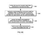
- FIG. 8Cis a flowchart of one embodiment of a process for selecting a critical constraint for use in the control process of FIGS. 8A & 8B , in accordance with one or more aspects of the present invention
- FIGS. 9A & 9Bdepict an alternate embodiment of a control process for a cooling apparatus, such as one of the cooling apparatuses depicted in FIGS. 7A-7D , in accordance with one or more aspects of the present invention
- FIGS. 10A & 10Bdepict an another embodiment of a control process for a cooling apparatus, such as one of the cooling apparatuses depicted in FIGS. 7A-7D , in accordance with one or more aspects of the present invention
- FIGS. 11A-11Ddepict a further embodiment of a control process for a cooling apparatus, such as one of the cooling apparatuses depicted in FIGS. 7A-7D , in accordance with one or more aspects of the present invention.
- FIG. 12depicts one embodiment of a computer program product or a computer-readable storage medium incorporating one or more aspects of the present invention.
- an electronics rackmay comprise a portion of an electronic system, a single electronic system or multiple electronic systems, for example, in one or more sub-housings, blades, books, drawers, nodes, compartments, etc., having one or more heat-generating electronic components disposed therein.
- An electronic system(s) within an electronics rackmay be movable or fixed relative to the electronics rack, with rack-mounted electronic drawers and blades of a blade center system being two examples of electronic systems (or subsystems) of an electronics rack to be cooled.
- “Electronic component”refers to any heat-generating electronic component of, for example, a computer system or other electronic system requiring cooling.
- an electronic componentmay comprise one or more integrated circuit dies, and/or other electronic devices to be cooled, such as one or more electronics cards comprising a plurality of memory modules (such as one or more dual in-line memory modules (DIMMs)), or one or more data storage devices (e.g., replaceable hard drives).
- DIMMsdual in-line memory modules
- data storage devicese.g., replaceable hard drives.
- primary heat-generating componentrefers to a primary heat-generating electronic component (such as an integrated circuit die) within an electronic system
- secondary heat-generating componentrefers to an electronic component (such as a replaceable disk drive) generating less heat than the primary heat-generating electronic component.
- the primary heat-generating electronic componentmay generate, in one embodiment, two times or more heat than the secondary heat-generating component.
- liquid-cooled structurerefers to thermally conductive structures having one or more channels (or passageways) formed therein or passing therethrough, which facilitate the flow of liquid coolant through the structure.
- tubingis provided extending through the liquid-cooled cold plate or liquid-cooled cold rail.
- An “air-to-liquid heat exchanger” or “air-to-liquid heat exchange assembly”means any heat exchange mechanism characterized as described herein through which liquid coolant can circulate; and includes, one or more discrete air-to-liquid heat exchangers coupled either in series or in parallel.
- An air-to-liquid heat exchangermay comprise, for example, one or more coolant flow paths, formed of thermally conductive tubing (such as copper or other tubing) in thermal or mechanical contact with a plurality of air-cooled cooling fins. Size, configuration and construction of the air-to-liquid heat exchanger can vary without departing from the scope of the invention disclosed. Still further, “coolant-cooled structure” refers to, for example, a liquid-cooled structure or a heat exchanger, such as an air-to-liquid heat exchanger. A coolant-cooled structure comprises one or more coolant-carrying passages through which coolant circulates to dissipate heat from an electronics rack.
- a “data center”refers to a computer installation containing one or more electronics racks to be cooled. As a specific example, a data center may comprise one or more rows of rack-mounted computer units, such as server units.
- coolant used within the cooled electronic apparatuses disclosed hereinis water.
- the concepts presentedare readily adapted to use with other types of coolant.
- the coolantmay comprise a brine, a fluorocarbon liquid, a liquid metal, or other similar coolant, or refrigerant, while still maintaining the advantages and unique features of the present invention.
- FIG. 1depicts a raised floor layout of an air cooled data center 100 typical in the prior art, wherein multiple electronics racks 110 are disposed in one or more rows.
- a data centersuch as depicted in FIG. 1 may house several hundred, or even several thousand microprocessors.
- chilled airenters the computer room via perforated floor tiles 160 from a supply air plenum 145 defined between the raised floor 140 and a base or sub-floor 165 of the room. Cooled air is taken in through louvered covers at air inlet sides 120 of the electronics racks and expelled through the back (i.e., air outlet sides 130 ) of the electronics racks.
- Each electronics rack 110may have one or more air moving devices (e.g., fans or blowers) to provide forced inlet-to-outlet airflow to cool the electronic devices within the rack unit.
- the supply air plenum 145provides conditioned and cooled air to the air-inlet sides of the electronics racks via perforated floor tiles 160 disposed in a “cold” aisle of the computer installation.
- the conditioned and cooled airis supplied to plenum 145 by one or more air conditioning units 150 , also disposed within the data center 100 .
- Room airis taken into each air conditioning unit 150 near an upper portion thereof. This room air may comprise, in part, exhausted air from the “hot” aisles of the computer installation defined, for example, by opposing air outlet sides 130 of the electronics racks 110 .
- FIGS. 2-4illustrate various embodiments of a data center implementation employing a liquid-based cooling system.
- FIG. 2depicts one rack-level liquid-cooling solution which utilizes chilled facility water to remove heat from the computer installation room, thereby transferring the cooling burden from the air-conditioning unit(s) to the building's chilled water coolers.
- facility-chilled water 200circulates through one or more liquid-to-liquid heat exchangers 210 , coupled via a system coolant loop 211 , to individual electronics racks 220 within the computer room.
- Rack unit 220includes one or more air-moving devices 230 for moving air flow from an air inlet side to an air outlet side across one or more drawer units 240 containing heat-generating electronic components to be cooled.
- a front cover 250 attached to the rackcovers the air inlet side
- a back cover 255 attached to the rackcovers the air outlet side
- a side car disposed adjacent to (and/or attached to) the rackincludes a heat exchanger 260 for cooling air circulating through the rack unit.
- the liquid-to-liquid heat exchangers 210are multiple computer room water-conditioning (CRWC) units which are coupled to receive building chilled facility water 200 .
- the building chilled facility wateris used to cool the system coolant within system coolant loop 211 , which is circulating through air-to-liquid heat exchanger 260 .
- the rack unit in this exampleis assumed to comprise a substantially enclosed housing, wherein the same air circulates through the housing that passes across the air-to-liquid heat exchanger 260 . In this manner, heat generated within the electronics rack is removed from the enclosed housing via the system coolant loop, and transferred to the facility coolant loop for removal from the computer installation room.
- FIG. 3depicts another embodiment of a rack-level, liquid-cooling solution, which again uses chilled facility water to remove heat from the computer installation room, thereby transferring the cooling burden from the air-conditioning unit(s) to the building's chilled water coolers.
- a coolant distribution unit 300 for a data centeris illustrated.
- coolant distribution unit 300Within coolant distribution unit 300 is a power/control element 312 , a reservoir/expansion tank 313 , a liquid-to-liquid heat exchanger 314 , a pump 315 (often accompanied by a redundant second pump), facility water inlet 316 and outlet 317 supply pipes, a supply manifold 318 supplying water or system coolant to the electronics racks 110 via couplings 320 and lines 322 , and a return manifold 319 receiving water or system coolant from the electronics racks 110 , via lines 323 and couplings 321 .
- a power/control element 312Within coolant distribution unit 300 is a power/control element 312 , a reservoir/expansion tank 313 , a liquid-to-liquid heat exchanger 314 , a pump 315 (often accompanied by a redundant second pump), facility water inlet 316 and outlet 317 supply pipes, a supply manifold 318 supplying water or system coolant to the electronics racks 110 via couplings
- Each electronics rackincludes (in one example) a power/control unit 330 for the electronics rack, multiple electronic systems or subsystems 340 , a system coolant supply manifold 350 , and a system coolant return manifold 360 .
- each electronics rack 110is disposed on raised floor 140 of the data center with lines 322 providing system coolant to system coolant supply manifolds 350 and lines 323 facilitating return of system coolant from system coolant return manifolds 360 being disposed in the supply air plenum beneath the raised floor.
- system coolant supply manifold 350provides system coolant to cooling apparatuses disposed within the electronic systems or subsystems (for example, to liquid-cooled cold plates or cold rails) via flexible hose connections 351 , which are disposed between the supply manifold and the respective electronic systems within the rack.
- system coolant return manifold 360is coupled to the electronic systems via flexible hose connections 361 .
- Quick connect couplingsmay be employed at the interface between flexible hoses 351 , 361 and the individual electronic systems.
- these quick connect couplingsmay comprise various types of commercially available couplings, such as those available from Colder Products Company, of St. Paul, Minn., USA, or Parker Hannifin, of Cleveland, Ohio, USA.
- electronics rack 110may also include an air-to-liquid heat exchanger, for example, disposed at an air outlet side thereof, which also receives system coolant from the system coolant supply manifold 350 and returns system coolant to the system coolant return manifold 360 .
- an air-to-liquid heat exchangerfor example, disposed at an air outlet side thereof, which also receives system coolant from the system coolant supply manifold 350 and returns system coolant to the system coolant return manifold 360 .
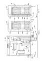
- FIG. 4illustrates another embodiment of a liquid-cooled electronics rack and cooling system therefor, in accordance with one or more aspects of the present invention.
- the electronics rack 400has a side car structure 410 associated therewith or attached thereto, which includes an air-to-liquid heat exchanger 415 through which air circulates from an air outlet side of electronics rack 400 towards an air inlet side of electronics rack 400 , for example, in a closed loop path in a manner similar to that illustrated above in connection with the cooling implementation of FIG. 2 .
- the cooling systemcomprises an economizer-based, warm-liquid coolant loop 420 , which comprises multiple coolant tubes (or lines) connecting, in the example depicted, air-to-liquid heat exchanger 415 in series fluid communication with a coolant supply manifold 430 associated with electronics rack 400 , and connecting in series fluid communication, a coolant return manifold 431 associated with electronics rack 400 , a cooling unit 440 of the cooling system, and air-to-liquid heat exchanger 415 .
- multiple coolant tubes (or lines)connecting, in the example depicted, air-to-liquid heat exchanger 415 in series fluid communication with a coolant supply manifold 430 associated with electronics rack 400 , and connecting in series fluid communication, a coolant return manifold 431 associated with electronics rack 400 , a cooling unit 440 of the cooling system, and air-to-liquid heat exchanger 415 .
- coolant flowing through warm-liquid coolant loop 420flows via coolant supply plenum 430 to one or more electronic systems of electronics rack 400 , and in particular, one or more cold plates and/or cold rails 435 associated with the electronic systems, before returning via coolant return manifold 431 to warm-liquid coolant loop 420 , and subsequently to cooling unit 440 disposed (for example) outdoors from the data center.
- cooling unit 440includes a filter 441 for filtering the circulating liquid coolant, a condenser (or air-to-liquid heat exchanger) 442 for removing heat from the liquid coolant, and a pump 443 for returning the liquid coolant through warm-liquid coolant loop 420 to air-to-liquid heat exchanger 415 , and subsequently to the liquid-cooled electronics rack 400 .
- hose barb fittings 450 and quick disconnect couplings 455may be employed to facilitate assembly or disassembly of warm-liquid coolant loop 420 .
- warm liquid coolingor “warm coolant cooling” refers to a cooling approach employing an outdoor-air-cooled heat exchange unit as the cooling unit 440 .
- This heat exchange unitis coupled via, at least in part, warm-liquid coolant loop 420 to dissipate heat from the coolant passing through the cold plates and/or cold rails 435 associated with the electronic systems.
- the heatis dissipated from the coolant to outdoor ambient air.
- temperature of the coolant within warm-liquid coolant loop 420is greater than the temperature of the outdoor ambient air to which heat is dissipated.
- temperature of the coolant entering the liquid-cooled structures within the electronic systemmay be greater than or equal to 27° C.
- ambient temperaturemight be 30° C., and coolant temperature 35° C. leaving the air-to-liquid heat exchanger 442 of the cooling unit.
- the cooled electronic system depictedthus facilitates a chiller-less data center.
- a liquid-cooling solutionprovides highly energy efficient cooling of the electronic systems of the electronics rack, using liquid (e.g., water), that is cooled via circulation through the air-to-liquid heat exchanger located outdoors (i.e., a dry cooler) with external ambient air being pumped through the dry cooler. Note that this warm coolant-cooling approach of FIG. 4 is presented by way of example only.
- cold coolant-coolingcould be substituted for the cooling unit 440 depicted in FIG. 4 .
- Such cold coolant-coolingmight employ building chilled facility coolant to cool the liquid coolant flowing through the liquid-cooled electronics rack, and associated air-to-liquid heat exchanger (if present), in a manner such as described above in connection with FIGS. 2 & 3 .
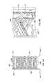
- FIGS. 5A & 5Bdepict in greater detail one embodiment of a liquid-cooled electronics rack, such as depicted in FIG. 4 , in accordance with one or more aspects of the present invention.
- liquid-cooled electronics rack 400comprises a plurality of electronic systems 500 , within which one or more electronic components are to be liquid-cooled via, for example, one or more cold plates or cold rails, as described below.
- the cooling systemincludes coolant loop 420 coupled in fluid communication with coolant supply manifold 430 and coolant return manifold 431 , both of which may comprise vertically-oriented manifolds attached to liquid-cooled electronics rack 400 .
- the rack-level coolant distribution systemfurther includes individual node-level supply hoses 510 supplying coolant from coolant supply manifold 430 to cold plates and cold rails within the electronic systems 500 .
- coolant supply manifold 430may be (in one embodiment) a vertically-oriented manifold with a plurality of coupling connections 511 disposed along the manifold, one for each electronic system 500 having one or more electronic components to be liquid-cooled. Coolant leaves the individual electronic systems 500 via node-level return hoses 520 , which couple the individual electronic systems (or nodes) to coolant return manifold 431 , and hence, to coolant loop 420 .
- FIG. 5Bcoolant supply manifold 430 may be (in one embodiment) a vertically-oriented manifold with a plurality of coupling connections 511 disposed along the manifold, one for each electronic system 500 having one or more electronic components to be liquid-cooled. Coolant leaves the individual electronic systems 500 via node-level return hoses 520 , which
- relatively warm-liquid coolantsuch as water
- the cooling unitis supplied from the cooling unit, either directly, or through one or more air-to-liquid heat exchanger(s) 415 (of FIG. 4 ), and hot coolant is returned via the coolant return manifold to the cooling unit.
- the node-level supply and return hoses 510 , 520are flexible hoses.
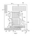
- FIG. 6illustrates one embodiment of a cooled electronic system 500 component layout, wherein one or more air-moving devices 600 provide forced air flow 601 to cool multiple components 610 within electronic system 500 . Cool air is taken in through a front 602 and exhausted out a back 603 of the electronic system (or drawer).
- the multiple components to be cooledinclude, for example, multiple processor modules to which liquid-cooled cold plates 620 (of the liquid-based cooling apparatus) are coupled, as well as multiple arrays 631 , 632 of electronics cards 630 (e.g., memory modules such as dual in-line memory modules (DIMMs)), which are to be thermally coupled to one or more liquid-cooled cold rails 625 .
- thermally coupledrefers to a physical thermal transport path being established between components, for example, between an electronics card and a liquid-cooled cold rail for the conduction of heat from one to the other.
- the illustrated liquid-based cooling approachfurther includes multiple coolant-carrying tubes connecting in fluid communication liquid-cooled cold plates 620 and liquid-cooled cold rails 625 .
- These coolant-carrying tubescomprise (for example), a coolant supply tube 640 , multiple bridge tubes 641 , and a coolant return tube 642 .
- bridge tubes 641connect one liquid-cooled cold rail 625 in series between the two liquid-cooled cold plates 620 , and connect in parallel two additional liquid-cooled cold rails 625 between the second liquid-cooled cold plate 620 and the coolant return tube 642 . Note that this configuration is provided by way of example only. The concepts disclosed herein may be readily adapted to use with various configurations of cooled electronic system layouts.
- the liquid-cooled cold railsare elongate, thermally conductive structures comprising one or more channels through which liquid coolant passes, for example, via one or more tubes extending through the structures.
- the liquid-cooled cold railsare disposed, in the embodiment illustrated, at the ends of the two arrays (or banks) 631 , 632 of electronics cards 630 , and multiple thermal spreaders are provided coupling in thermal communication electronics cards 630 and liquid-cooled cold rails 635 .
- FIGS. 7A-7Ddepict various alternate embodiments of a cooled electronic system, in accordance with one or more aspects of the present invention.
- These cooled electronic systemcomprise various embodiments of a cooling apparatus which include dynamic control and limiting of energy consumed by the cooling apparatus, as described hereinbelow.
- a cooling apparatuswhich includes one or more coolant-cooled structures, such as one or more liquid-cooled structures (or cold plates) and/or one or more air-to-liquid heat exchangers, associated with an electronics rack for facilitating dissipation of heat from the electronics rack in a manner, for example, such as described above in connection with FIG. 4 .
- the one or more coolant-cooled structuresinclude one or more coolant-carrying passages.
- the cooling apparatusfurther includes a coolant loop coupled in fluid communication with the coolant-carrying passage(s) of the coolant-cooled structure(s) and one or more heat exchange units coupled to facilitate heat transfer from coolant within the coolant loop.
- the heat exchange unit(s)is coupled in fluid communication with the coolant loop.
- the cooling apparatusfurther includes N controllable components associated with at least one of the coolant loop or the at least one heat exchange unit to facilitate at least one of circulating of coolant through the coolant loop or transfer of heat from the coolant via the heat exchange unit(s), wherein N ⁇ 1.
- a controlleris coupled to the N controllable components. The controller dynamically adjusts operation of the N controllable components, based on Z input parameters and one or more specified constraints, to provide a specified cooling to the at least one coolant-cooled structure, while limiting energy consumed by the N controllable components, wherein Z ⁇ 1.
- the Z input parameterscomprise Z measured input parameters, which may be dynamically-varying inputs or variables ascertained by the controller.
- the input parametersmay comprise temperature readings, pressure readings, humidity readings, dew point readings, etc.
- an air-side, economizer-based data centeris depicted, which is implemented with a control process to limit data center cooling power consumption, in accordance with one or more aspects of the present invention.
- An air-side, economizer-based data center cooling systemincludes one or more electronics racks which are partially or completely liquid-cooled, as well as, in one embodiment, a side car structure, an air-side economizer (i.e., heat exchange unit), and one or more optional liquid-to-liquid heat exchange buffers (depicted in FIGS. 7B-7D ).
- substantially all the heat dissipated by the electronic components within the electronics rackis transferred to the liquid coolant; for example, partially within the electronics rack via one or more liquid-cooled structures, and partially at the side car structure, via an air-to-liquid heat exchanger.
- This heatis then convected to the air-side economizer, where it is dissipated to the outdoor ambient air.
- the rate of heat transfer at the electronics rack(s)is predominantly governed by the coolant flow rate through the coolant-cooled structure(s).
- the heat transfer rateis governed by the economizer air-side flow rate and the liquid-coolant flow rate through the economizer.
- the heat transfer rateis a non-linear, monotonically increasing function of air-side flow rate and liquid coolant flow rate.
- worst case scenariorefers to the highest ambient air temperature and highest heat dissipation at the electronics rack, and in a more general sense, the highest heat dissipation within the data center, occurring simultaneously. This situation is rare, and might not even occur over the lifecycle of the data center. The typical result is a relatively high (more than required) cooling power consumption for almost the entire lifecycle of the data center.
- dynamic control processesbased on data center heat dissipation and, for example, ambient air temperature, which minimize (in one embodiment) the cooling power consumption, and thereby reduce the data center energy usage.
- FIGS. 7A-7Ddepict alternate embodiments of a cooled electronic system, in accordance with one or more aspects of the present invention, each comprising one or more electronics racks and a cooling apparatus such as described herein.
- FIG. 7Adepicts one embodiment of a single coolant loop configuration which includes one or more electronics racks 400 , each with a side car structure 410 associated therewith or attached thereto, which includes an air-to-liquid heat exchanger 415 through which air circulates from an air outlet side of electronics rack 400 towards an air inlet side of electronics rack 400 , for example, in a closed loop path in a manner similar to that illustrated above in connection with the cooling implementation of FIG. 2 .
- the cooling systemcomprises an economizer-based, warm-liquid coolant loop 700 , which comprises multiple coolant tubes (or lines) connecting, in the example, depicted, air-to-liquid heat exchanger 415 in series fluid communication with a coolant supply manifold 430 associated with electronics rack 400 , and connecting in series fluid communication a coolant return manifold 431 associated with electronics rack 400 , and a coolant loop 700 .
- hose barb fittings 450 and quick disconnect couplings 455may be employed to facilitate assembly or disassembly of coolant loop 700 .
- Coolant loop 700includes a coolant pump 701 and is coupled in fluid communication with a heat exchange unit 710 , which in the depicted embodiment, comprises a dry cooler, wherein ambient air 711 is forced across the heat exchange unit 710 via one or more fans 703 .
- An electronically-controlled bypass valve 702is coupled in parallel with heat exchange unit 710 to allow controlled bypassing of coolant within the coolant loop from passing through the heat exchange unit.
- coolant flowing through warm-liquid coolant loop 700flows via coolant supply plenum 430 to one or more electronic systems of electronics racks 400 , and in particular, one or more liquid-cooled cold structures 435 associated with the electronic systems, before returning via coolant return manifold 431 to coolant loop 700 , and subsequently, to heat exchange unit 710 disposed (for example) outdoors from a data center wall 705 .
- the heat exchange unitmay include a filter (not shown) for filtering the circulating liquid coolant, as well as an air-to-liquid heat exchanger for removing heat from the liquid coolant. Note in the single-loop, cooled electronic system example of FIG.
- air-to-liquid heat exchanger 415 and liquid-cooled cold structures 435are examples of coolant-cooled structures associated with the electronics rack for facilitating dissipation of heat from the electronics rack.
- controllable components associated with at least one of the coolant loop 700 or the at least one heat exchange unit 710include coolant pump 701 , fan 703 , and recirculation (or bypass) valve 702 .
- warm-liquid coolingor “warm-coolant cooling” refer to a cooling approach employing an outdoor-air-cooled heat exchange unit.
- This heat exchange unitis coupled via, at least in part, coolant loop 700 to dissipate heat from the coolant passing through the coolant-cooled structures 435 , 415 associated with the electronic systems.
- this heatis dissipated from the coolant to outdoor ambient air.
- temperature of the coolant within warm-liquid coolant loop 700is greater than the temperature of the outdoor ambient air to which heat is dissipated.
- temperature of coolant entering the liquid-cooled structures within the electronic systemsmay be greater than or equal to 27° C., and less than or equal to 45° C.
- the cooled electronic system depicted in FIG. 7Athus facilitates a chiller-less data center.
- a liquid-cooling solutionprovides highly energy efficient cooling of the electronic systems of the electronics rack, using liquid (e.g., water) that is cooled via circulation through the heat exchange unit(s) 710 located outdoors (i.e., a dry cooler) with external ambient air 711 being pumped through the dry cooler.
- liquide.g., water
- the heat exchange unit(s) 710located outdoors (i.e., a dry cooler) with external ambient air 711 being pumped through the dry cooler.
- FIGS. 7B-7DSeveral alternative approaches are depicted in FIGS. 7B-7D , and described below.
- a controller 720is also provided as part of the cooling apparatus.
- input parameters to controller 720may include ambient temperature and humidity 721 , temperature of one or more electronic components 722 , such as processor, memory or hard drive components, a dew point sensor 723 within the data center, and temperature and pressure 724 of coolant within the coolant loop 700 , for example, temperature and pressure of coolant being provided to the air-to-liquid heat exchanger 415 of the side car structure 410 in the embodiment illustrated in FIG. 7A .
- the N controllable componentsinclude coolant pump(s) 701 , fans(s) 703 , and electronically-controlled bypass valve 702 .
- Controller 720provides a corresponding operational setting to each of these components as described herein via control lines 730 , 731 , 732 , respectively.
- the operational control setting for coolant pump(s) 701might comprise an RPM value
- the operational setting for fan(s) 703might comprise a different RPM value
- an operational setting for bypass valve 702might comprise a percent (%) open parameter, which controls the positioning of the valve.
- other input parameters, or other output operational control settingsmay be employed or provided.
- FIG. 7Bdepicts a dual-loop cooling apparatus embodiment, which is similar to the single loop embodiment described above in connection with FIG. 7A , except that a liquid-to-liquid heat exchanger 740 is provided within the data center as a buffer to coolant flowing through coolant loop 700 and a secondary coolant flowing through heat exchange unit 710 .
- a liquid-to-liquid heat exchanger 740is provided within the data center as a buffer to coolant flowing through coolant loop 700 and a secondary coolant flowing through heat exchange unit 710 .
- controller 720 of the cooling apparatus of FIG. 7Bprovides, via a control line 733 , an output operational control setting for the second coolant pump 741 in addition to those operational control settings provided in connection with the embodiment of FIG. 7A .
- FIG. 7Cdepicts a further cooling apparatus embodiment, wherein multiple heat exchangers 740 are coupled in series between coolant loop 700 and heat exchange unit 710 . These heat exchangers may each comprise a liquid-to-liquid heat exchanger, a liquid-to-gas heat exchanger, or even a gas-to-gas heat exchanger. Additionally, the cooling apparatus of FIG. 7C includes additional cooling pumps 751 , each associated with a respective coolant loop 750 coupling two coolant-to-coolant heat exchangers 740 .
- Controller 720includes similar temperature and pressure sensors for determining temperature and pressure of coolant within each coolant loop 700 , 750 , 704 , and outputs operational control settings for the additional controllable components comprising coolant pumps 751 , in addition to the above-discussed controllable components.
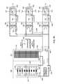
- FIG. 7Ddepicts an alternate cooling apparatus embodiment, wherein the additional coolant loops are coupled in parallel rather than in series, as depicted in FIG. 7C .
- coolant loop 700is coupled via multiple parallel-connected, coolant-to-coolant heat exchangers 740 to multiple heat exchange units 710 via respective secondary coolant loops 704 , and secondary coolant pumps 741 .
- coolant pumps 751are provided, if desired, for supplemental coolant pumping through the parallel-connected, coolant-to-coolant heat exchangers 740 .
- coolant pumps 701 , 741are provided, if desired, for supplemental coolant pumping through the parallel-connected, coolant-to-coolant heat exchangers 740 .
- each secondary coolant loop 704includes a respective coolant pump 741 , and a respective heat exchange unit 710 , as well as one or more fans 703 associated with the heat exchange unit, and an electronically-controlled bypass valve 702 for selectively bypassing a portion of the secondary coolant from the heat exchange unit 710 .
- Quick connect couplings 760may be employed to facilitate assembly or disassembly of the cooling apparatus illustrated.
- FIGS. 7C & 7Ddepict cooling apparatuses wherein the RPMs of a plurality of economizer fans, and a plurality of coolant pumps are regulated individually, or simultaneously, to limit or optimize data cooling energy consumption, and subsequently, to reduce the total data center energy consumption.
- control process embodiments presented hereinare based on regulating, for example, the economizer fan RPMs, as well as the coolant pump(s) RPMs, and in certain embodiments, one or more flow control valve settings.
- Z input parametersmay include various input conditions or parameters, such as outdoor ambient air temperature and humidity, data center temperature and humidity, temperature of one or more electronic components within the electronics rack being cooled, temperature and pressure of one or more coolants within the cooling apparatus, flow rates through one or more cooling loops, as well as a dew point of the data center.
- Z input parametersmay include various input conditions or parameters, such as outdoor ambient air temperature and humidity, data center temperature and humidity, temperature of one or more electronic components within the electronics rack being cooled, temperature and pressure of one or more coolants within the cooling apparatus, flow rates through one or more cooling loops, as well as a dew point of the data center.
- economizer fansare running at maximum RPMs for 40° C. ambient air, and a maximum heat load dissipation at the electronics rack, they may run at a lower RPM (for example, 50% of max RPMs), at a lower ambient air temperature (for example, 20° C.). This can reduce the fan power consumption by 87.5% of maximum.
- FIGS. 8A-8Cdepict one embodiment of a control process which can be employed to minimize data center cooling power consumption, in accordance with one or more aspects of the present invention.
- This control processcomprises a data structure or table-based control approach, as explained below.
- Control processingbegins with a selected, prespecified data structure (or table) being provided to the control process 800 , one embodiment of which is depicted in FIG. 8B .
- Controllable componentssuch as fans and coolant pumps are initially set with a maximum RPM, and any recirculation valves are fully closed 805 .
- RPMmaximum speed of the cooling apparatus
- all specified constraints for the operation of the cooling apparatusshould be satisfied 810 .
- determining whether constraints are metmight comprise determining whether temperature of an electronic component, such as a processor, is less than a specified temperature (T CPU ⁇ T CPU,spec ?), determining whether temperature of an associated memory module, such as a dual in-line memory module, is less than a specified, dual in-line memory module temperature (T DIMM ⁇ T DIMM,spec ?), and/or determining whether air inlet temperature to the electronics rack is less than a specified air inlet temperature to the electronics rack (T rack air in ⁇ T rack, air in, spec ?). If “no”, then a warning message of insufficient cooling is displayed, and the controller maintains the controllable components at their maximum operational control settings 815 .
- the Z input parameters for the selected, specified tableare checked to ascertain a critical constraint 820 .
- the tablemay comprise “r” number of rows, and “Z” number of input parameters (or conditions).
- the input parameters (or conditions)could be any or all of the monitored variables, such as the temperatures, pressures, humidity, flow rates, and power consumption at various locations within the cooled electronic system.
- the output conditions in the tableare the operational control settings for, for example, fans and coolant pumps, as well as any recirculation valve positions. In case of a single input condition, there is no need to identify the critical constraint, and the valve setting(s) and the output condition(s) can be assigned defined in the table.
- the critical constraintis identified before applying values of the output conditions. Based on the actual value of the monitored input parameters, each input can be assigned a row number. The input condition having the highest row number is, in one embodiment, the critical constraint. For example, let there be two input conditions, I1 and I2, and let their actual monitored values be I1,x and I2,x. With the selected table, the value I1,x could be between the table values of I1,r1 and I1,r2 (where row r1 ⁇ r2), while the value I2,x could be between the values of I2,r3 and I2,r4 (where row r3 ⁇ r4).
- the controllerobtains a value for each input parameter (or condition) in the selected table 825 , and associates a row number with each input parameter using the obtained values of the input parameters 830 . If the value of the obtained input parameter lies between two table values, then the lower row number is employed. The controller then chooses the highest row number by identifying the critical constraint(s), i.e., in one embodiment, the input parameter value(s) having the highest row number 835 . The corresponding set of operational control settings (or output conditions) in this row of the plurality of rows in the specified table, are then applied, based on the highest row number identified 840 .
- the health/operating conditions of the cooled electronic systemmay next be reported 845 .
- temperature, pressure, humidity, flow rates, power consumption, valve positions, etc.can be reported or displayed to reflect the outcome of the applied set of operational control settings (or output conditions).
- the controllermay check if maintenance is required 850 . For example, maintenance may be required based on hours of system operation, or any similar condition. If “yes”, then a “maintenance required” message may be displayed, and processing may switch to maximum operational control settings 855 . If “no”, then processing continues in normal operation, which may include a check for whether a manual override has been made 860 .
- the systemwill switch to manual mode settings 865 , and continue to run in the manual mode until user input is provided to reenter the control loop 870 . If there is no manual override, then the system will continue normal operation, and the controller will, after waiting a time interval t 825 , return to check the current input parameters on the selected table 820 .
- the table values comprising the input parameters and sets of operational control settingsmay be determined through experimental testing in a lab environment.
- the loop configurationcan be initially installed such that the dry cooler receives a supply of air at a controlled temperature. This can be carried out using an air heater apparatus upstream of the dry cooler, and by initially having the dry cooler located indoors to facilitate testing before transferring to an outdoor environment.
- the air heater apparatuscan comprise an electrical, resistance-based heater, that is conductively coupled to metal heat sinks and fans being used to force air through the heated heat sinks.
- an air-to-liquid heat exchanger with a water heater fluidically coupled to the water loop of the heat exchangercould be used as the air heater apparatus.
- the systemcan be started, that is, the coolant pumps and fans and the IT load, and finally the air heater apparatus, may be activated.
- the coolant pumps and fanscan be set to their maximum speeds, and the IT load can be ramped up slowly to maximum load condition.
- air temperatures at the inlet to the dry cooler heat exchanger coilscan be measured and compared to the highest temperature expected annually, based on local weather data. If the inlet air temperature to the dry cooler coil is less than the maximum air temperature expected based on local weather conditions (as would be likely for most of the year), the heaters are switched ON and controlled until the maximum air inlet temperature condition at the inlet to the dry cooler is met.
- the cooling apparatusis run at these conditions until steady state is reached.
- the speeds of the various coolant pumps and fansare ramped down slowly in small increments from their maximum speed. While reducing the fan and pump speeds, the speed of each coolant pumping device can be reduced in small steps that are related to each other, that is, using a factor, or the speeds can be reduced individually using a fixed percentage change between the maximum and minimum allowable pump or fan speeds. After each decrement of the pump and fan speeds, steady state is allowed to be reached and various device and coolant temperatures of interest are recorded.
- the table generated using the experiments described abovethen provides a guiding relationship between the coolant and device temperatures and the fan and pump speeds, while assuming a maximum IT load and a maximum inlet air temperature to the dry cooler heat exchanger coil.
- the use of the maximum IT load and dry cooler air inlet temperaturesresults in a conservative control of the system with respect to the pump and fan flow rates.
- cooling energy efficiencyis achieved using the rational reduction of pump and fan speeds for lower coolant or device temperatures.
- experimentscan be carried out to parametrically test various factors that relate the fan and pump speeds to each other. Alternatively, various individual profiles for decreasing the individual coolant pumps and fans could be tested. After a matrix of tests has been performed, the most energy efficient (i.e., best performing) parameter inputs to the table can be determined and chosen.
- a typical day for different seasonsi.e., fall, winter, spring and summer
- a typical day for different seasonsi.e., fall, winter, spring and summer
- the dry coolercan be commissioned and the coolant loop can be allowed to become fully operational.
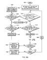
- FIGS. 9A & 9Bdepict an alternate control process, wherein the controllable components are initiated at maximum operational control settings, and control setting changes are made to all controllable components in a related manner.
- control processingis initiated 900 by setting the controllable components to maximum operational control settings, and any recirculation valves fully closed 905 .
- the constraint(s)should be satisfied 910 , and if “no”, processing determines whether the fans and coolant pumps are running at their maximum operational state and any recirculation valves are fully closed 915 . If “yes”, then an insufficient cooling warning is issued, and the controllable components continue to operate at their maximum operational control settings 920 .
- processingsets a “flag” variable equal to 2 940 , which indicates that operational control settings are to be increased, as explained further below. If the specified constraints are met 910 , then processing checks the margins by which each input parameter meets its associated constraint, and determines whether the minimum margin of the ascertained margins is greater than a minimum specified margin 925 . Note, in this regard, that margins (M 1 , M 2 . . . ) can be normalized to vary from 1 to 100, and that Z is (in one example) also the number of constraints.
- variable “flag”is assigned a value 1 945 , which is a reduce cooling power consumption mode, as explained below. If all the margins are not greater than the minimum specified margin, then processing checks to determine whether the fans and coolant pumps are running at their respective maximum operational control settings, and if all the recirculation, bypass valves are fully closed. If all the controllable components are running at their maximum state, then the system will continue to run at that state 935 . Otherwise, processing sets the “flag” variable to a value 2.
- processingnext determines whether the “flag” variable equals 1 950 , and if “yes”, determines whether the controllable components (or cooling devices) are all running at their minimum operational control settings 955 . If “no”, then processing reduces all controllable components by a corresponding ⁇ RPM, or opens the recirculation valves by a corresponding ⁇ % 960 , before returning to the process of FIG. 9A to determine whether maintenance is required 975 .
- processingdetermines whether the controllable components (or cooling devices) are running at their maximum operational control settings 965 , and if “no”, increases RPMs of all controllable components by ⁇ RPMs, or closes all recirculation valve(s) by ⁇ % 970 , after which processing returns to the control process of FIG. 9A to determine whether maintenance is required 975 .
- processingchecks whether maintenance is required 975 , and if “yes”, switches the controllable components to maximum operational control settings and displays a “maintenance required” indication 980 . If maintenance is not required, then processing determines whether there has been a manual override 985 , and if “yes”, switches to manual mode settings, and displays a “manual mode” indication 990 . Thereafter, processing waits a time interval t 995 before again checking whether the constraints have been met by the current input parameters 910 .
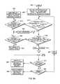
- FIGS. 10A & 10Bdepict another control process, in accordance with one or more aspects of the present invention, wherein the controllable components are initiated at maximum operational control settings, and control setting changes are made one component at a time.
- control processingis initiated 1000 by setting the controllable components to maximum operational control settings, and any recirculation bypass valves fully closed 1002 .
- the constraint(s)should be satisfied 1004 , and if “no”, then processing determines whether the fans and coolant pumps are running at their maximum operational state and any recirculation valves are fully closed 1006 . If “yes”, then an insufficient cooling warning is issued, and the controllable components continue to operate at their maximum control settings 1008 . If the fans and coolant pumps are not running at their maximum operational control settings 1006 , then processing sets a “flag” variable equal to 2 1016 , which indicates that operational control settings are to be serially, incrementally increased, as explained further below.
- processingchecks the margins by which each input parameter meets its associated constraint, and determines whether the minimum margin of the ascertained margins is greater than a minimum specified margin 1010 . If all of the ascertained margins are greater than the minimum specified margin, then the “flag” variable is assigned a value 1 1018 , indicative of a reduce cooling power consumption mode, as explained below. If all the margins are not greater than the minimum specified margin, then processing checks to determine whether the fans and coolant pumps are running at their respective maximum operational control settings, and all of the recirculation valves are fully closed 1012 . If all the controllable components are running at their maximum state, then processing will continue to run at that state 1014 . Otherwise, processing sets the “flag” variable to a value 2 1016 .
- processingnext determines whether the “flag” variable equals 1 1020 (that is, is the flag set to indicate a reduce cooling power consumption mode). If “yes”, then the states of the controllable components, e.g., fans and coolant pumps, are sequentially checked, for example, in descending order, starting with fan FN, followed by fan FN ⁇ 1, and so on, until reaching pump P1. Specifically, in the embodiment illustrated, the state of the N th fan (that is, fan FN) is initially checked 1022 .
- the state of the N th fanthat is, fan FN
- fan FNis not running at its minimum operational control setting, then fan FN is reduced by ⁇ RPM_FN 1024 , and control processing stores/remembers the latest state change by setting an “undo_flag” equal to zero 1026 , before returning to the processing of FIG. 10A .
- processingchecks whether fan FN ⁇ 1 is running at its minimum operational control state 1028 , and if “no”, reduces fan FN ⁇ 1 speed by ⁇ RPM_FN ⁇ 1 1030 . Processing repeats the inquiries until reaching fan FN1 to determine whether it is running at its minimum operational control state 1032 , and if “no”, reduces speed of fan FN1 by ⁇ RPM_F1 1034 .
- pump P2Nis evaluated to determine whether it is running at minimum operational control setting 1036 , and if “no”, speed of pump P2N is reduced by ⁇ RPM_P2N 1038 .
- processingevaluates pump P2N ⁇ 1 to determine whether it is running at its minimum operational control state 1040 , and if “no”, reduces speed of pump P2N ⁇ 1 by ⁇ RPM_P2N ⁇ 1 1042 .
- processinginitially checks the value of the “undo_flag” variable 1050 to see whether it equals 1. If “no”, then processing undoes the last operational control setting change 1052 , and returns to the processing of FIG. 10A . Assuming that the “undo_flag” variable is 1, then the states of the cooling devices, that is, the fans and pumps, are checked in ascending order, starting from pump P1, followed by pump P2, and so on, until fan FN. Note that in this embodiment, the ordering of the fans and pumps may be any desired order, but that the increasing of operational control settings would be in an opposite order from the decreasing of operational control settings described above.
- power consumptionmay be initially minimized by evaluating the highest-power-consuming components lost.
- the state of pump P1is initially checked to determine whether pump P1 is running at its maximum operational control setting 1054 , and if “no”, then the speed of pump P1 is increased by ⁇ RPM_P1 1056 .
- pump P2is evaluated to determine whether it is running at maximum operational control setting 1058 , and if “no”, the speed pump P2 is increased by ⁇ RPM_P2 1060 . This process is repeated until reaching pump P2N, and determining whether it is running at maximum operational control setting 1062 , and if “no”, then speed of pump P2N is increased by ⁇ RPM_P2N 1064 .
- processingdetermines whether fan F1 is running at maximum operational control setting 1066 , and if “no”, increases speed of fan F1 by ⁇ RPM_F1 1068 .
- processingdetermines whether fan F2 is running at maximum operational control setting 1070 , and if “no”, increases speed of fan F2 by ⁇ RPM_F2 1072 .
- processingchecks whether maintenance is required 1080 , and if “yes”, switches the controllable components to maximum operational control settings and displays a “maintenance required” indication 1082 . If maintenance is not required, then processing determines whether there has been a manual override 1084 , and if “yes”, switches to manual mode settings, and displays a “manual mode” indication 1086 . Otherwise, processing waits a time interval t 1088 before again checking whether the constraints have been met by the current input parameters 1004 .
- FIGS. 11A-11Ddepict another control process, in accordance with one or more aspects of the present invention, wherein the controllable components are initiated at maximum operational control settings, and control setting changes are made one at a time.
- This embodimentis similar to that described above in connection with FIGS. 10A-10B , except provision is made for also dynamically adjusting any recirculation valves within the cooling apparatus.
- control processingis initiated 1100 by setting the controllable components to maximum operational control settings, and the recirculation bypass valves fully closed 1102 .
- the constraint(s)should be satisfied 1104 , and if “no”, then processing determines whether the fans and coolant pumps are running at their maximum operational state and any recirculation valves are fully closed 1106 . If “yes”, then an insufficient cooling warning is issued, and the controllable components continue to operate at their maximum control settings 1108 . If the fans and coolant pumps are not running at their maximum operational control settings 1106 , then processing sets a “flag” variable equal to 2 1116 , which indicates that operational control settings are to be serially, incrementally increased, as explained further below.
- processingchecks the margins by which each input parameter meets its associated constraint, and determines whether the minimum margin of the ascertained margins is greater than a minimum specified margin 1110 . If all of the ascertained margins are greater than the minimum specified margin, then the “flag” variable is assigned a value 1 1118 , indicative of a reduce cooling power consumption mode, as explained below. If all the margins are not greater than the minimum specified margin, then processing checks to determine whether the fans and coolant pumps are running at their respective maximum operational control settings, and all of the recirculation valves are fully closed 1112 . If all the controllable components are running at their maximum state, then processing will continue to run at that state 1114 . Otherwise, processing sets the “flag” variable to a value 2 1116 .
- processingnext determines whether the “flag” variable equals 1 1120 (that is, is the flag set to indicate a reduce cooling power consumption mode). If “yes”, then the states of the controllable components, e.g., fans and coolant pumps, are sequentially checked, for example, in descending order, starting with fan FN, followed by fan FN ⁇ 1, and so on, until reaching pump P1. Specifically, in the embodiment illustrated, the state of the N th fan (that is, fan FN) is initially checked 1122 .
- the state of the N th fanthat is, fan FN
- fan FNis not running at its minimum operational control setting, then fan FN is reduced by ⁇ RPM_FN 1124 , and control processing stores/remembers the latest state change by setting an “undo_flag” equal to zero 1126 , before returning to the processing of FIG. 11A .
- processingchecks whether fan FN ⁇ 1 is running at its minimum operational control state 1128 , and if “no”, reduces fan FN ⁇ 1 speed by ⁇ RPM_FN ⁇ 1 1130 . Processing repeats the inquiries until reaching fan FN1 to determine whether it is running at its minimum operational control state 1132 , and if “no”, reduces fan FN1 speed by ⁇ RPM_F1 1134 .
- pump P2Nis evaluated to determine whether it is running at minimum operational control setting 1136 , and if “no”, speed of pump P2N is reduced by ⁇ RPM_P2N 1138 .
- processingevaluates pump P2N ⁇ 1 to determine whether it is running at its minimum operational control state 1140 , and if “no”, reduces speed of pump P2N ⁇ 1 by ⁇ RPM_P2N ⁇ 1 1142 .
- the processcontinues until pump P1 is reached and a determination is made whether pump P1 is running at its minimum operational control state 1144 , and if “no”, processing reduces speed of pump P1 by ⁇ RPM_P1 1146 .
- processingpasses to the flow of FIG. 11C , and determines whether recirculation valve VN is fully open 1145 , and if “no”, further opens the valve VN by ⁇ %_VN 1147 , before returning to FIG. 11B , to store/remember the latest change my setting the “undo_flag” equal to zero, and then returning to the process of FIG. 11A , wherein indicated.
- processingdetermines whether recirculation valve VN ⁇ 1 is fully open 1149 , and if “no”, incrementally opens valve VN ⁇ 1 by ⁇ %_VN-1 1151 .
- valve V1determines whether recirculation valve V1 is fully open 1153 , and if “no”, opens valve V1 by ⁇ %_V1 1155 . Otherwise, if all controllable components have been adjusted to conserve cooling energy, processing returns to the flow of FIG. 11A , where indicated.
- processinginitially checks the value of the “undo_flag” variable 1150 to see whether it equals 1. If “no”, then processing undoes the last operational control setting change 1152 , and returns to the processing of FIG. 11A , where indicated. Assuming that the “undo_flag” variable is 1, then the states of all cooling devices, that is, the fans, pumps, and recirculation valves are checked in ascending order, starting from recirculation valve V1 ( FIG. 11D ), followed by recirculation valve V2, and so on, until reaching fan FN. Note that in this embodiment, the ordering of the fans, pumps and valves may be any desired ordering, but that the increasing of operational control settings is in an opposite order from the decreasing of operational control settings described above.
- FIG. 11Devaluates and adjusts the recirculation valves to determine the incremental closures to be made in the increase cooling mode. Processing initially determines whether recirculation valve V1 is fully closed 1161 , and if “no”, incrementally closes recirculation valve V1 by ⁇ %_V1 1163 , before returning to the processing of FIG. 11A , where indicated. Once valve V1 is fully closed, processing determines whether recirculation valve V2 is fully closed 1165 , and if “no”, incrementally closes valve V2 by ⁇ %_V2 1167 .
- valve VNis reached, and processing determines whether recirculation valve VN is fully closed 1169 , and if “no”, incrementally closes valve VN by ⁇ %_VN 1171 . Once all recirculation valves are fully closed, processing continues with the control process of FIG. 11B , where indicated.
- additional coolingis provided, in this example, by checking the state of pump P1 to determine whether pump P1 is running at maximum operational control setting 1154 , and if “no”, then the speed of pump P1 is increased by ⁇ RPM_P1 1156 .
- pump P2is evaluated to determine whether it is running at maximum operational control setting 1158 , and if “no”, then the speed of pump P2 is increased by ⁇ RPM_P2 1160 . This process is repeated until reaching pump P2N, and determining whether it is running at maximum operational control setting 1162 , and if “no”, then the speed of pump P2N is increased by ⁇ RPM_P2N 1164 .
- processingdetermines whether fan F1 is running at maximum operational control setting 1166 , and if “no”, increases the speed of fan F1 by ⁇ RPM_F1 1168 .
- processingdetermines whether fan F2 is running at maximum operational control setting 1170 , and if “no”, increases the speed of fan F2 by ⁇ RPM_F2 1172 . This process is repeated until processing reaches fan FN, and determines whether fan FN is running at maximum operational control setting 1174 , and if “no”, increases the speed of fan FN by ⁇ RPM_FN 1176 , after which, processing returns to FIG. 11A , where indicated.
- processingchecks whether maintenance is required 1180 , and if “yes”, switches the controllable components to maximum operational control settings and displays a “maintenance required” indication 1182 . If maintenance is not required, then processing determines whether there has been a manual override 1184 , and if “yes”, switches to manual mode settings, and displays a “manual mode” indication 1186 . Otherwise, processing waits a time interval t 1188 before again checking whether the constraints have been met by the current input parameters 1104 .
- controllable componentsi.e., recirculation valves, pumps and fans (in this example)
- the componentsmay be numbered in any desired manner.
- the componentsmay be numbered based on physical location within the cooling system, or based on power that the components consume at their maximum state, with the highest number given to the unit that consumes the maximum power, and the lowest number given to the unit that consumes the minimum power.
- control aspects of the present inventionmay be embodied as a system, method or computer program product. Accordingly, aspects of the present invention may take the form of an entirely hardware embodiment, an entirely software embodiment (including firmware, resident software, micro-code, etc.) or an embodiment combining software and hardware aspects that may all generally be referred to herein as a “circuit,” “module” or “system”. Furthermore, control aspects of the present invention may take the form of a computer program product embodied in one or more computer readable medium(s) having computer readable program code embodied thereon.
- the computer readable mediummay be a computer readable signal medium or a computer readable storage medium.
- a computer readable signal mediummay be any non-transitory computer readable medium that is not a computer readable storage medium and that can communicate, propagate, or transport a program for use by or in connection with an instruction execution system, apparatus or device.
- a computer readable storage mediummay be, for example, but not limited to, an electronic, magnetic, optical, electromagnetic, infrared or semiconductor system, apparatus, or device, or any suitable combination of the foregoing. More specific examples (a non-exhaustive list) of the computer readable storage medium include the following: an electrical connection having one or more wires, a portable computer diskette, a hard disk, a random access memory (RAM), a read-only memory (ROM), an erasable programmable read-only memory (EPROM or Flash memory), an optical fiber, a portable compact disc read-only memory (CD-ROM), an optical storage device, a magnetic storage device, or any suitable combination of the foregoing.
- a computer readable storage mediummay be any tangible medium that can contain or store a program for use by or in connection with an instruction execution system, apparatus, or device.
- a computer program product 1200includes, for instance, one or more computer readable storage media 1202 to store computer readable program code means or logic 1204 thereon to provide and facilitate one or more aspects of the present invention.
- Program code embodied on a computer readable mediummay be transmitted using an appropriate medium, including but not limited to wireless, wireline, optical fiber cable, RF, etc., or any suitable combination of the foregoing.
- Computer program code for carrying out operations for aspects of the present inventionmay be written in any combination of one or more programming languages, including an object oriented programming language, such as Java, Smalltalk, C++ or the like, and conventional procedural programming languages, such as the “C” programming language, assembler or similar programming languages.
- the program codemay execute entirely on the user's computer, partly on the user's computer, as a stand-alone software package, partly on the user's computer and partly on a remote computer or entirely on the remote computer or server.
- the remote computermay be connected to the user's computer through any type of network, including a local area network (LAN) or a wide area network (WAN), or the connection may be made to an external computer (for example, through the Internet using an Internet Service Provider).
- LANlocal area network
- WANwide area network
- Internet Service Providerfor example, AT&T, MCI, Sprint, EarthLink, MSN, GTE, etc.
- These computer program instructionsmay also be stored in a computer readable medium that can direct a computer, other programmable data processing apparatus, or other devices to function in a particular manner, such that the instructions stored in the computer readable medium produce an article of manufacture including instructions which implement the function/act specified in the flowchart and/or block diagram block or blocks.
- the computer program instructionsmay also be loaded onto a computer, other programmable data processing apparatus, or other devices to cause a series of operational steps to be performed on the computer, other programmable apparatus or other devices to produce a computer implemented process such that the instructions which execute on the computer or other programmable apparatus provide processes for implementing the functions/acts specified in the flowchart and/or block diagram block or blocks.
- each block in the flowchart or block diagramsmay represent a module, segment, or portion of code, which comprises one or more executable instructions for implementing the specified logical function(s).
- the functions noted in the blockmay occur out of the order noted in the figures. For example, two blocks shown in succession may, in fact, be executed substantially concurrently, or the blocks may sometimes be executed in the reverse order, depending upon the functionality involved.
- one or more aspects of the present inventionmay be provided, offered, deployed, managed, serviced, etc. by a service provider who offers management of customer environments.
- the service providercan create, maintain, support, etc. computer code and/or a computer infrastructure that performs one or more aspects of the present invention for one or more customers.
- the service providermay receive payment from the customer under a subscription and/or fee agreement, as examples. Additionally or alternatively, the service provider may receive payment from the sale of advertising content to one or more third parties.
- an applicationmay be deployed for performing one or more aspects of the present invention.
- the deploying of an applicationcomprises providing computer infrastructure operable to perform one or more aspects of the present invention.
- a computing infrastructuremay be deployed comprising integrating computer readable code into a computing system, in which the code in combination with the computing system is capable of performing one or more aspects of the present invention.
- a process for integrating computing infrastructurecomprising integrating computer readable code into a computer system
- the computer systemcomprises a computer readable medium, in which the computer medium comprises one or more aspects of the present invention.
- the code in combination with the computer systemis capable of performing one or more aspects of the present invention.
- computing environments of other architecturescan incorporate and use one or more aspects of the present invention.
- the network of nodescan include additional nodes, and the nodes can be the same or different from those described herein.
- many types of communications interfacesmay be used.
- a data processing system suitable for storing and/or executing program codeincludes at least one processor coupled directly or indirectly to memory elements through a system bus.
- the memory elementsinclude, for instance, local memory employed during actual execution of the program code, bulk storage, and cache memory which provide temporary storage of at least some program code in order to reduce the number of times code must be retrieved from bulk storage during execution.
- I/O devicescan be coupled to the system either directly or through intervening I/O controllers.
- Network adaptersmay also be coupled to the system to enable the data processing system to become coupled to other data processing systems or remote printers or storage devices through intervening private or public networks. Modems, cable modems, and Ethernet cards are just a few of the available types of network adapters.
- a method or device that “comprises”, “has”, “includes” or “contains” one or more steps or elementspossesses those one or more steps or elements, but is not limited to possessing only those one or more steps or elements.
- a step of a method or an element of a device that “comprises”, “has”, “includes” or “contains” one or more featurespossesses those one or more features, but is not limited to possessing only those one or more features.
- a device or structure that is configured in a certain wayis configured in at least that way, but may also be configured in ways that are not listed.
- Undo_Flag1 means last change was reverted.
- X2 Relationship variable between ⁇ RPM_F2 and ⁇ RPM_F1X3 Relationship variable between ⁇ RPM_F3 and ⁇ RPM_F1 XN Relationship variable between ⁇ RPM_FN and ⁇ RPM_F1 Y1 Relationship variable between ⁇ RPM_P1 and ⁇ RPM_F1 Y2 Relationship variable between ⁇ RPM_P2 and ⁇ RPM_F1 Y2N Relationship variable between ⁇ RPM_P2N and ⁇ RPM_F1 W1 Relationship variable between ⁇ % Open_V1 and ⁇ RPM_F1 W2 Relationship variable between ⁇ % Open_V2 and ⁇ RPM_F1 WN Relationship variable between ⁇ % Open_VN and ⁇ RPM_F1
Landscapes
- Engineering & Computer Science (AREA)
- Physics & Mathematics (AREA)
- General Engineering & Computer Science (AREA)
- Microelectronics & Electronic Packaging (AREA)
- Theoretical Computer Science (AREA)
- Thermal Sciences (AREA)
- General Physics & Mathematics (AREA)
- Computer Hardware Design (AREA)
- Human Computer Interaction (AREA)
- Automation & Control Theory (AREA)
- Cooling Or The Like Of Electrical Apparatus (AREA)
Abstract
Description
ΔRPM—F2=X2*ΔRPM—F1,ΔRPM—F3=×3*ΔRPM—F1, . . . ,ΔRPM—FN=XN*ΔRPM—F1 (1)
ΔRPM—P1=Y1*ΔRPM—F1,ΔRPM—P2−Y2*ΔRMP—F1, . . . ,ΔRPM—P2N=Y2N*ΔRPM—F1 (2)
Δ% Open—V1=W1*ΔRPM—F1,Δ% Open—V2=W2*ΔRPM—F1, . . . ,Δ% Open—VN=WN*ΔRPM—F1 (3)
where ΔRPM_F1 is the change in RPM for fan F1, ΔRPM_F2 is the change in RPM to fan F2, etc.
| TABLE 1 | |
| Variable | Definition |
| DP | Dew Point |
| H | Humidity |
| P | Pressure |
| T | Temperature |
| F1 | 1stFan or Fan F1 |
| F2 | 2ndfan or Fan F2 |
| FN-1 | (N-1)th Fan (or Fan FN-1) |
| FN | Nth Fan (or Fan FN) |
| P1 | 1stPump or Pump P1 |
| P2 | 2ndPump or Pump P2 |
| P2N-1 | (2N-1)th Pump (or Pump P2N-1) |
| P2N | 2Nth Pump (or Pump P2N) |
| V1 | Recirculation valve V1 |
| V2 | Recirculation valve V2 |
| VN-1 | Recirculation valve VN-1 ((N-1)th Valve) |
| VN | Recirculation valve VN (Nth Valve) |
| ΔRPM_F1 | Change in RPM for Fan F1 |
| ΔRPM_F2 | Change in RPM for Fan F2 |
| ΔRPM_FN-1 | Change in RPM for (N-1)thFan (or Fan FN-1) |
| ΔRPM_FN | Change in RPM for Nth Fan (or Fan FN) |
| ΔRPM_P1 | Change in RPM for Pump P1 |
| ΔRPM_P2 | Change in RPM for Pump P2 |
| ΔRPM_P2N-1 | Change in RPM for (2N-1)thPump (or Pump P2N-1) |
| ΔRPM_P2N | Change in RPM for 2NthPump (or Pump P2N) |
| Δ% Open_V1 | Change in % Open for the Recirculation valve V1 |
| Δ% Open_V2 | Change in % Open for the Recirculation valve V2 |
| Δ% Open_VN-1 | Change in % Open for the Recirculation valve VN-1 |
| ((N-1)th Valve) | |
| Δ% Open_VN | Change in % Open for the Recirculation valve VN |
| (NthValve) | |
| Δ%_V1 | Change in % Open for the Recirculation valve V1 |
| Δ%_V2 | Change in % Open for the Recirculation valve V2 |
| Δ%_VN-1 | Change in % Open for the Recirculation valve VN-1 |
| ((N-1)thValve) | |
| Δ%_VN | Change in % Open for the Recirculation valve VN |
| (NthValve) | |
| IZ | ZthInput condition |
| Z | Total number of input conditions or inputs |
| I1, 1 | Value of input condition 1 at row 1 |
| I1, 2 | Value of input condition 1 at row 2 |
| I1, r1 | Value of input condition 1 at row r1 |
| I1, r2 | Value of input condition 1 at row r2 |
| I1, r | Value of input condition 1 at row r |
| I2, 1 | Value of input condition 2 at row 1 |
| I2, 2 | Value of input condition 2 at row 2 |
| I2, r3 | Value of input condition 2 at row r3 |
| I2, r4 | Value of input condition 2 at row r4 |
| I2, r | Value of input condition 2 at row r |
| IZ, 1 | Value of input condition Z at row 1 |
| IZ, 2 | Value of input condition Z at row 2 |
| IZ, r | Value of input condition Z at row r |
| F1, 1 | Value of Fan F1 RPM at row 1 |
| F1, 2 | Value of Fan F1 RPM at row 2 |
| F1, r | Value of Fan F1 RPM at row r |
| F2, 1 | Value of Fan F2 RPM at row 1 |
| F2, 2 | Value of Fan F2 RPM at row 2 |
| F2, r | Value of Fan F2 RPM at row r |
| FN, 1 | Value of Fan FN RPM at row 1 |
| FN, 2 | Value of Fan FN RPM at row 2 |
| FN, r | Value of Fan FN RPM at row r |
| Flag | Flag = 1 means reduce RPMs and/or open recirculation |
| valve(s) and Flag = 2 means increase RPMs and/or | |
| close recirculation valve(s) | |
| P1, 1 | Value of Pump P1 RPM at row 1 |
| P1, 2 | Value of Pump P1 RPM at row 2 |
| P1, r | Value of Pump P1 RPM at row r |
| P2, 1 | Value of Pump P2 RPM at row 1 |
| P2, 2 | Value of Pump P2 RPM at row 2 |
| P2, r | Value of Pump P2 RPM at row r |
| P2N, 1 | Value of Pump P2N RPM at row 1 |
| P2N, 2 | Value of Pump P2N RPM at row 2 |
| P2N, r | Value of Pump P2N RPM at row r |
| V1, 1 | Value of Recirculation Valve V1% Open at row 1 |
| V1, 2 | Value of Recirculation Valve V1% Open at row 2 |
| V1, r | Value of Recirculation Valve V1% Open at row r |
| V2, 1 | Value of Recirculation Valve V2% Open at row 1 |
| V2, 2 | Value of Recirculation Valve V2% Open at row 2 |
| V2, r | Value of Recirculation Valve V2% Open at row r |
| VN, 1 | Value of Recirculation Valve VN % Open at row 1 |
| VN, 2 | Value of Recirculation Valve VN % Open at row 2 |
| VN, r | Value of Recirculation Valve VN % Open at row r |
| M1 | Margin by which the first constraint is met |
| M2 | Margin by which the second constraint is met |
| Mz | Margin by which the Zthconstraint is met |
| Z | Total number of constraints |
| TCPU | Hottest CPU or Maximum CPU Temperature |
| TCPU, spec | Maximum allowed CPU Temperature |
| TDIMM | Hottest DIMM or Maximum DIMM Temperature |
| TDIMM, Spec | Maximum allowed DIMM Temperature |
| Track | Rack Inlet Air Temperature |
| Track | Maximum allowed Rack Inlet Air Temperature |
| Track DP | Rack Dew Point Temperature |
| Track | Allowed Rack Dew Point Temperature |
| Undo_Flag | Undo_Flag = 0 means a change was made to reduce |
| the cooling power. Undo_Flag = 1 means last | |
| change was reverted. | |
| X2 | Relationship variable between ΔRPM_F2 and |
| ΔRPM_F1 | |
| X3 | Relationship variable between ΔRPM_F3 and |
| ΔRPM_F1 | |
| XN | Relationship variable between ΔRPM_FN and |
| ΔRPM_F1 | |
| Y1 | Relationship variable between ΔRPM_P1 and |
| ΔRPM_F1 | |
| Y2 | Relationship variable between ΔRPM_P2 and |
| ΔRPM_F1 | |
| Y2N | Relationship variable between ΔRPM_P2N and |
| ΔRPM_F1 | |
| W1 | Relationship variable between Δ% Open_V1 and |
| ΔRPM_F1 | |
| W2 | Relationship variable between Δ% Open_V2 and |
| ΔRPM_F1 | |
| WN | Relationship variable between Δ% Open_VN and |
| ΔRPM_F1 | |
Claims (18)
Priority Applications (3)
| Application Number | Priority Date | Filing Date | Title |
|---|---|---|---|
| US13/305,967US9043035B2 (en) | 2011-11-29 | 2011-11-29 | Dynamically limiting energy consumed by cooling apparatus |
| PCT/EP2012/068516WO2013079237A1 (en) | 2011-11-29 | 2012-09-20 | Dynamically limiting energy consumed by cooling apparatus |
| US13/705,300US9052722B2 (en) | 2011-11-29 | 2012-12-05 | Dynamically limiting energy consumed by cooling apparatus |
Applications Claiming Priority (1)
| Application Number | Priority Date | Filing Date | Title |
|---|---|---|---|
| US13/305,967US9043035B2 (en) | 2011-11-29 | 2011-11-29 | Dynamically limiting energy consumed by cooling apparatus |
Related Child Applications (1)
| Application Number | Title | Priority Date | Filing Date |
|---|---|---|---|
| US13/705,300ContinuationUS9052722B2 (en) | 2011-11-29 | 2012-12-05 | Dynamically limiting energy consumed by cooling apparatus |
Publications (2)
| Publication Number | Publication Date |
|---|---|
| US20130138252A1 US20130138252A1 (en) | 2013-05-30 |
| US9043035B2true US9043035B2 (en) | 2015-05-26 |
Family
ID=47044977
Family Applications (2)
| Application Number | Title | Priority Date | Filing Date |
|---|---|---|---|
| US13/305,967Expired - Fee RelatedUS9043035B2 (en) | 2011-11-29 | 2011-11-29 | Dynamically limiting energy consumed by cooling apparatus |
| US13/705,300Expired - Fee RelatedUS9052722B2 (en) | 2011-11-29 | 2012-12-05 | Dynamically limiting energy consumed by cooling apparatus |
Family Applications After (1)
| Application Number | Title | Priority Date | Filing Date |
|---|---|---|---|
| US13/705,300Expired - Fee RelatedUS9052722B2 (en) | 2011-11-29 | 2012-12-05 | Dynamically limiting energy consumed by cooling apparatus |
Country Status (2)
| Country | Link |
|---|---|
| US (2) | US9043035B2 (en) |
| WO (1) | WO2013079237A1 (en) |
Cited By (34)
| Publication number | Priority date | Publication date | Assignee | Title |
|---|---|---|---|---|
| US20140124190A1 (en)* | 2012-11-08 | 2014-05-08 | International Business Machines Corporation | Coolant-conditioning unit with automated control of coolant flow valves |
| US20150096715A1 (en)* | 2013-10-08 | 2015-04-09 | Hon Hai Precision Industry Co., Ltd. | Heat dissipation system |
| US20150245541A1 (en)* | 2014-02-25 | 2015-08-27 | Fujitsu Limited | Data center |
| US20170196124A1 (en)* | 2015-10-23 | 2017-07-06 | Huawei Technologies Co., Ltd. | Heat-Pipe Heat Dissipation System and Power Device |
| US9795062B1 (en)* | 2016-06-29 | 2017-10-17 | Amazon Technologies, Inc. | Portable data center for data transfer |
| US9930814B2 (en)* | 2012-11-16 | 2018-03-27 | Fujitsu Limited | Modular data center and method of controlling modular data center |
| US20180286463A1 (en)* | 2017-03-16 | 2018-10-04 | International Business Machines Corporation | System and Method for Controlling Environmental Conditions within an Automated Data Storage Library |
| US10129611B2 (en) | 2014-09-27 | 2018-11-13 | Rf Code, Inc. | System and method for monitoring sensor output |
| US10395695B2 (en) | 2017-03-16 | 2019-08-27 | International Business Machines Corporation | Data storage library with media acclimation device and methods of acclimating data storage media |
| US10398061B1 (en) | 2016-06-29 | 2019-08-27 | Amazon Technologies, Inc. | Portable data center for data transfer |
| US10418071B2 (en) | 2017-03-16 | 2019-09-17 | International Business Machines Corporation | Data storage library with positive pressure system |
| US10418063B2 (en) | 2017-03-16 | 2019-09-17 | International Business Machines Corporation | Data storage library with interior access regulation |
| US10417851B2 (en) | 2017-03-16 | 2019-09-17 | International Business Machines Corporation | Data storage library with service mode |
| US10431254B2 (en) | 2017-03-16 | 2019-10-01 | International Business Machines Corporation | System for providing an acclimation enclosure for a data storage library |
| US10509421B2 (en) | 2017-03-16 | 2019-12-17 | International Business Machines Corproation | Method for controlling environmental conditions within an automated data storage library |
| US10548239B1 (en) | 2018-10-23 | 2020-01-28 | Google Llc | Cooling electronic devices in a data center |
| US10548240B1 (en) | 2019-01-11 | 2020-01-28 | Google Llc | Cooling electronic devices in a data center |
| US10551806B2 (en) | 2017-03-16 | 2020-02-04 | International Business Machines Corporation | System for providing an access area for a data storage library |
| US10566023B2 (en) | 2017-03-16 | 2020-02-18 | International Business Machines Corporation | Data storage library with service mode for protecting data storage drives |
| US10576589B2 (en)* | 2014-09-30 | 2020-03-03 | The Boeing Company | Cooling system for use with a power electronics assembly and method of manufacturing thereof |
| US10645847B2 (en) | 2018-04-20 | 2020-05-05 | Google Llc | Cooling electronic devices in a data center |
| US10660240B2 (en) | 2017-03-16 | 2020-05-19 | International Business Machines Corporation | Method for providing an access area for a data storage library |
| US10681846B2 (en) | 2018-04-19 | 2020-06-09 | Google Llc | Cooling electronic devices in a data center |
| US10890955B2 (en) | 2017-03-16 | 2021-01-12 | International Business Machines Corporation | System for controlling environmental conditions within an automated data storage library |
| US10965525B1 (en) | 2016-06-29 | 2021-03-30 | Amazon Technologies, Inc. | Portable data center for data transfer |
| US10966352B2 (en) | 2018-09-24 | 2021-03-30 | Google Llc | Cooling electronic devices in a data center |
| US11076509B2 (en) | 2017-01-24 | 2021-07-27 | The Research Foundation for the State University | Control systems and prediction methods for it cooling performance in containment |
| US11202393B2 (en)* | 2020-02-05 | 2021-12-14 | Baidu Usa Llc | Multi-function adapting modules for electronics cooling |
| US20220087054A1 (en)* | 2020-09-14 | 2022-03-17 | Nvidia Corporation | Unified fan-less radiator for datacenter cooling systems |
| US11500430B2 (en) | 2017-03-16 | 2022-11-15 | International Business Machines Corporation | Data storage library with service mode for protecting data storage drives |
| US12029015B2 (en) | 2020-12-23 | 2024-07-02 | Microsoft Technology Licensing, Llc | Control systems for air-assisted and liquid-cooled enclosures |
| US20240377144A1 (en)* | 2021-07-16 | 2024-11-14 | Bae Systems Plc | Cooling system |
| US12200914B2 (en) | 2022-01-24 | 2025-01-14 | Coolit Systems, Inc. | Smart components, systems and methods for transferring heat |
| US12213289B2 (en) | 2011-07-27 | 2025-01-28 | Coolit Systems, Inc. | Modular heat-transfer systems |
Families Citing this family (62)
| Publication number | Priority date | Publication date | Assignee | Title |
|---|---|---|---|---|
| US9681587B2 (en)* | 2007-08-30 | 2017-06-13 | Pce, Inc. | System and method for cooling electronic equipment |
| US9395771B1 (en) | 2007-10-26 | 2016-07-19 | Pce, Inc. | Plenum pressure control system |
| US9723759B2 (en) | 2009-11-30 | 2017-08-01 | Facebook, Inc. | Cooling servers in a data center using fans external to servers |
| US10492331B1 (en)* | 2010-09-29 | 2019-11-26 | Amazon Technologies, Inc. | System and method for cooling power distribution units |
| US9307674B2 (en) | 2011-05-06 | 2016-04-05 | International Business Machines Corporation | Cooled electronic system with liquid-cooled cold plate and thermal spreader coupled to electronic component |
| US9027360B2 (en) | 2011-05-06 | 2015-05-12 | International Business Machines Corporation | Thermoelectric-enhanced, liquid-based cooling of a multi-component electronic system |
| US9901008B2 (en) | 2014-10-27 | 2018-02-20 | Ebullient, Inc. | Redundant heat sink module |
| US9901013B2 (en) | 2011-06-27 | 2018-02-20 | Ebullient, Inc. | Method of cooling series-connected heat sink modules |
| US9854714B2 (en) | 2011-06-27 | 2017-12-26 | Ebullient, Inc. | Method of absorbing sensible and latent heat with series-connected heat sinks |
| US9832913B2 (en) | 2011-06-27 | 2017-11-28 | Ebullient, Inc. | Method of operating a cooling apparatus to provide stable two-phase flow |
| US9848509B2 (en) | 2011-06-27 | 2017-12-19 | Ebullient, Inc. | Heat sink module |
| US9854715B2 (en) | 2011-06-27 | 2017-12-26 | Ebullient, Inc. | Flexible two-phase cooling system |
| US8687364B2 (en) | 2011-10-28 | 2014-04-01 | International Business Machines Corporation | Directly connected heat exchanger tube section and coolant-cooled structure |
| US9043035B2 (en) | 2011-11-29 | 2015-05-26 | International Business Machines Corporation | Dynamically limiting energy consumed by cooling apparatus |
| US9658629B2 (en) | 2012-03-22 | 2017-05-23 | Seagate Technology Llc | Method and apparatus for controlling the temperature of components |
| US8885335B2 (en)* | 2012-10-26 | 2014-11-11 | Facebook, Inc. | Server cooling by airflow throttling |
| GB2508920A (en) | 2012-12-17 | 2014-06-18 | Ibm | Cooling of a memory device |
| US10653044B2 (en) | 2013-01-10 | 2020-05-12 | International Business Machines Corporation | Energy efficiency based control for a cooling system |
| US9313930B2 (en) | 2013-01-21 | 2016-04-12 | International Business Machines Corporation | Multi-level redundant cooling system for continuous cooling of an electronic system(s) |
| US9351430B2 (en) | 2013-06-13 | 2016-05-24 | Microsoft Technology Licensing, Llc | Renewable energy based datacenter cooling |
| US9851726B2 (en) | 2013-09-04 | 2017-12-26 | Panduit Corp. | Thermal capacity management |
| US9538689B2 (en) | 2013-09-25 | 2017-01-03 | Globalfoundries Inc. | Data center cooling with critical device prioritization |
| US9357681B2 (en)* | 2014-05-22 | 2016-05-31 | Amazon Technologies, Inc. | Modular data center row infrastructure |
| CN104039117B (en)* | 2014-06-03 | 2017-01-04 | 华为技术有限公司 | A kind of heat abstractor, cooling control method and controller |
| EP3167345A4 (en)* | 2014-07-08 | 2018-02-21 | ADC Technologies Inc. | Robust redundant-capable leak-resistant cooled enclosure wall |
| CN105430997B (en)* | 2014-09-22 | 2019-03-12 | 中国移动通信集团广东有限公司 | A heat pipe internal circulation type secondary refrigerant loop server cabinet cooling system |
| US9852963B2 (en) | 2014-10-27 | 2017-12-26 | Ebullient, Inc. | Microprocessor assembly adapted for fluid cooling |
| AU2015339773A1 (en)* | 2014-10-27 | 2017-06-15 | Ebullient, Llc | Two-phase cooling system component |
| US20160116218A1 (en) | 2014-10-27 | 2016-04-28 | Ebullient, Llc | Heat exchanger with helical passageways |
| US10184699B2 (en) | 2014-10-27 | 2019-01-22 | Ebullient, Inc. | Fluid distribution unit for two-phase cooling system |
| US20160120059A1 (en) | 2014-10-27 | 2016-04-28 | Ebullient, Llc | Two-phase cooling system |
| EP3026991B1 (en)* | 2014-11-24 | 2018-01-10 | Vertiv S.R.L. | Conditioning unit of the indirect free cooling type, method of operation of such a conditioning unit, and apparatus for carrying out such method |
| EP3250865B1 (en) | 2015-01-30 | 2021-03-03 | Hewlett-Packard Enterprise Development LP | Scalable coolant distribution unit |
| TWI687639B (en)* | 2015-06-26 | 2020-03-11 | 美商三角設計公司 | Leak tolerant liquid cooling system employing improved air purging mechanism |
| US10156873B2 (en)* | 2015-12-21 | 2018-12-18 | Dell Products, L.P. | Information handling system having fluid manifold with embedded heat exchanger system |
| US10146231B2 (en)* | 2015-12-21 | 2018-12-04 | Dell Products, L.P. | Liquid flow control based upon energy balance and fan speed for controlling exhaust air temperature |
| US10238011B1 (en)* | 2017-10-10 | 2019-03-19 | Baidu Usa Llc | Optimal controller for hybrid liquid-air cooling system of electronic racks of a data center |
| US10893633B2 (en) | 2018-11-13 | 2021-01-12 | Modine Manufacturing Company | Method of cooling an electronics cabinet |
| US11778779B2 (en)* | 2018-11-22 | 2023-10-03 | Denso Corporation | Electronic component cooling device |
| US10834838B1 (en) | 2018-12-12 | 2020-11-10 | Amazon Technologies, Inc. | Collapsible and expandable data center infrastructure modules |
| TWI697765B (en)* | 2019-03-13 | 2020-07-01 | 緯創資通股份有限公司 | Adapting device and cooling system having the same |
| US11382232B1 (en) | 2019-03-28 | 2022-07-05 | Amazon Technologies, Inc. | Self-standing modular data center infrastructure system |
| CN110345549B (en)* | 2019-06-27 | 2024-04-02 | 广东西江数据科技有限公司 | Liquid cooling data center waste heat recovery system |
| EP3829279B1 (en)* | 2019-11-29 | 2024-01-24 | Ovh | Cooling arrangement for autonomous cooling of a rack |
| US11765864B2 (en) | 2019-08-26 | 2023-09-19 | Ovh | Cooling arrangement for a rack hosting electronic equipment and at least one fan |
| CN112702886B (en)* | 2019-10-22 | 2022-09-02 | 华为技术有限公司 | Liquid cooling heat dissipation system, heat dissipation control method and control chip |
| US11212943B2 (en) | 2020-02-21 | 2021-12-28 | Nvidia Corporation | Universal pluggable datacenter cooling system |
| TWI709364B (en)* | 2020-02-24 | 2020-11-01 | 美商美國未來科技公司 | Adjusting device for computer water cooling |
| US12328851B2 (en) | 2021-01-27 | 2025-06-10 | Nvidia Corporation | Intelligent refrigerant-assisted liquid-to-air heat exchanger for datacenter cooling systems |
| US11341994B1 (en)* | 2021-05-26 | 2022-05-24 | Quantum Corporation | Tape library system with integrated, feedback-based environmental and data durability control |
| US11778789B2 (en)* | 2021-06-07 | 2023-10-03 | International Business Machines Corporation | Constant temperature closed-loop airflow containment |
| US11844194B2 (en)* | 2021-06-22 | 2023-12-12 | Rockwell Automation Technologies, Inc. | Power electronic cooling system and method |
| EP4120047A1 (en)* | 2021-07-16 | 2023-01-18 | BAE SYSTEMS plc | Cooling system |
| EP4142444B1 (en)* | 2021-08-31 | 2024-06-12 | Ovh | Method for controlling a cooling system for autonomous cooling of a rack |
| CN114269129A (en)* | 2021-12-30 | 2022-04-01 | 北京字节跳动网络技术有限公司 | Data center cooling system and data center |
| US20230354548A1 (en)* | 2022-04-29 | 2023-11-02 | Cisco Technology, Inc. | Air cooling, latent heat cooling, and power supply cooling |
| US12259280B1 (en)* | 2022-07-01 | 2025-03-25 | ZT Group Int'l, Inc. | Apparatus providing liquid temperature data from individual direct cold plate cooling units |
| US20240237311A1 (en)* | 2023-01-06 | 2024-07-11 | Delta Electronics, Inc. | Heat dissipation system and solid-state transformer power apparatus |
| US12200912B2 (en)* | 2023-01-23 | 2025-01-14 | ZT Group Int'l, Inc. | Hybrid liquid cooling system for a computing rack |
| CN116860087B (en)* | 2023-07-04 | 2025-01-24 | 深圳市倍联德实业有限公司 | A host control method, system and related equipment based on environmental monitoring |
| EP4507465A1 (en)* | 2023-08-07 | 2025-02-12 | Ovh | Datacenter liquid cooling arrangements with power estimation and related fan and pump control |
| CN120475691A (en)* | 2025-07-16 | 2025-08-12 | 江苏谷峰电力科技股份有限公司 | Method and system for cooling high-power cabinet of computing center |
Citations (117)
| Publication number | Priority date | Publication date | Assignee | Title |
|---|---|---|---|---|
| US2907406A (en) | 1957-01-02 | 1959-10-06 | Donaldson Co Inc | Dry type air cleaner |
| US3807493A (en) | 1971-09-28 | 1974-04-30 | Kooltronic Fan Co | Heat exchanger using u-tube heat pipes |
| US5168921A (en) | 1991-12-23 | 1992-12-08 | Thermacore, Inc. | Cooling plate with internal expandable heat pipe |
| US5414591A (en) | 1991-04-15 | 1995-05-09 | Hitachi, Ltd. | Magnetic disk storage system |
| TW323643U (en) | 1995-03-28 | 1997-12-21 | Shinn Fu Corp | Oil safety releasing valve structure improvement for jack |
| US5794454A (en) | 1996-12-04 | 1998-08-18 | International Business Machines Corporation | Cooling device for hard to access non-coplanar circuit chips |
| US6011371A (en) | 1997-10-22 | 2000-01-04 | Hewlett-Packard Company | Proportional integral fan controller for electronic device |
| US20010000880A1 (en) | 1999-03-29 | 2001-05-10 | International Business Machines Corporation | Supplemental heating for variable load evaporative cold plates |
| US6263959B1 (en) | 1998-04-13 | 2001-07-24 | Furukawa Electric Co. Ltd. | Plate type heat pipe and cooling structure using it |
| US6305180B1 (en)* | 1999-09-13 | 2001-10-23 | British Broadcasting Corporation | Cooling system for use in cooling electronic equipment |
| US6400045B1 (en) | 2000-03-31 | 2002-06-04 | Fujitsu Limited | Cooling fan controller |
| US6411512B1 (en) | 1999-06-29 | 2002-06-25 | Delta Engineers | High performance cold plate |
| US6434000B1 (en) | 1998-12-03 | 2002-08-13 | Iv Phoenix Group, Inc. | Environmental system for rugged disk drive |
| US6462949B1 (en) | 2000-08-07 | 2002-10-08 | Thermotek, Inc. | Electronic enclosure cooling system |
| US6480014B1 (en) | 1999-12-14 | 2002-11-12 | High Connection Density, Inc. | High density, high frequency memory chip modules having thermal management structures |
| US6548894B2 (en) | 2000-11-30 | 2003-04-15 | International Business Machines Corporation | Electronic module with integrated programmable thermoelectric cooling assembly and method of fabrication |
| US6557354B1 (en) | 2002-04-04 | 2003-05-06 | International Business Machines Corporation | Thermoelectric-enhanced heat exchanger |
| US6775137B2 (en) | 2002-11-25 | 2004-08-10 | International Business Machines Corporation | Method and apparatus for combined air and liquid cooling of stacked electronics components |
| US20050068728A1 (en) | 2003-09-30 | 2005-03-31 | International Business Machines Corporation | Thermal dissipation assembly and fabrication method for electronics drawer of a multiple-drawer electronics rack |
| US6934118B2 (en) | 2002-01-29 | 2005-08-23 | Hitachi Global Storage Technologies Netherlands B.V. | Car disk drive unit |
| US7002799B2 (en) | 2004-04-19 | 2006-02-21 | Hewlett-Packard Development Company, L.P. | External liquid loop heat exchanger for an electronic system |
| US7042726B2 (en) | 2004-01-30 | 2006-05-09 | Isothermal Systems Research, Inc. | Low momentum loss fluid manifold system |
| US20060146497A1 (en) | 2004-12-30 | 2006-07-06 | Intel Corporation | Heat exchanger for memory modules |
| US20060250772A1 (en) | 2005-05-04 | 2006-11-09 | Silicon Graphics, Inc. | Liquid DIMM Cooler |
| US20060250770A1 (en) | 2005-05-06 | 2006-11-09 | International Business Machines Corporation | Apparatus and method for facilitating cooling of an electronics rack employing a closed loop heat exchange system |
| US7151668B1 (en) | 2004-10-28 | 2006-12-19 | Muskin, Inc. | Memory heat sink |
| US7165412B1 (en)* | 2004-11-19 | 2007-01-23 | American Power Conversion Corporation | IT equipment cooling |
| US20070034356A1 (en) | 2002-11-01 | 2007-02-15 | Cooligy, Inc. | Cooling systems incorporating heat exchangers and thermoelectric layers |
| US7233501B1 (en) | 2004-09-09 | 2007-06-19 | Sun Microsystems, Inc. | Interleaved memory heat sink |
| US20070187069A1 (en) | 2004-07-20 | 2007-08-16 | Furukawa-Sky Aluminum Corp. | Heat Pipe heat sink |
| US7273090B2 (en) | 2005-06-29 | 2007-09-25 | Intel Corporation | Systems for integrated cold plate and heat spreader |
| US7286355B2 (en) | 2002-09-11 | 2007-10-23 | Kioan Cheon | Cooling system for electronic devices |
| US20070263356A1 (en) | 2006-05-02 | 2007-11-15 | Raytheon Company | Method and Apparatus for Cooling Electronics with a Coolant at a Subambient Pressure |
| US7310737B2 (en) | 2003-06-30 | 2007-12-18 | Hewlett-Packard Development Company, L.P. | Cooling system for computer systems |
| US20070291452A1 (en) | 2006-06-14 | 2007-12-20 | Gilliland Don A | Heat Transfer Systems for Dissipating Thermal Loads From a Computer Rack |
| US7365985B1 (en) | 2004-09-29 | 2008-04-29 | Super Talent Electronics, Inc. | Memory module assembly including heat sink attached to integrated circuits by adhesive |
| US20080112075A1 (en) | 2004-11-03 | 2008-05-15 | Xyratex Technology Limited | Tempreature Control Apparatus for a Hard Disk Drive and a Method of Varying the Temperature of Hard Drive |
| US7385810B2 (en) | 2005-04-18 | 2008-06-10 | International Business Machines Corporation | Apparatus and method for facilitating cooling of an electronics rack employing a heat exchange assembly mounted to an outlet door cover of the electronics rack |
| US7388749B1 (en) | 2006-01-03 | 2008-06-17 | Emc Corporation | Support carrier for a disk-drive with integrated heat-sink |
| US20080155990A1 (en) | 2006-12-27 | 2008-07-03 | Ashish Gupta | Socket enabled current delivery to a thermoelectric cooler to cool an in-substrate voltage regulator |
| US7395851B2 (en) | 2005-08-08 | 2008-07-08 | Fu Zhun Precision Industry (Shenzhen) Co., Ltd. | Heat dissipation device |
| US7420804B2 (en) | 2004-06-30 | 2008-09-02 | Intel Corporation | Liquid cooling system including hot-swappable components |
| US20080239564A1 (en) | 2005-09-16 | 2008-10-02 | Xyratex Technology Limited | Method and Apparatus for Controlling the Temperature of a Disk Drive During Manufacture |
| US7436663B2 (en) | 2006-07-07 | 2008-10-14 | Hitachi, Ltd. | Disk array system |
| US7440278B2 (en) | 2005-05-19 | 2008-10-21 | Cooler Master Co., Ltd. | Water-cooling heat dissipator |
| US20080259566A1 (en) | 2007-04-16 | 2008-10-23 | Stephen Samuel Fried | Efficiently cool data centers and electronic enclosures using loop heat pipes |
| US20080259567A1 (en) | 2006-10-10 | 2008-10-23 | International Business Machines Corporation | Conductive heat transport cooling system and method for a multi-component electronics system |
| US7443672B2 (en) | 2006-10-03 | 2008-10-28 | Fu Zhun Precision Industry (Shen Zhen) Co., Ltd. | Video graphics array (VGA) card assembly |
| US7450385B1 (en) | 2007-06-15 | 2008-11-11 | International Business Machines Corporation | Liquid-based cooling apparatus for an electronics rack |
| US20080313492A1 (en) | 2007-06-12 | 2008-12-18 | Hansen Peter A | Adjusting a Cooling Device and a Server in Response to a Thermal Event |
| US20080310105A1 (en) | 2007-06-14 | 2008-12-18 | Chia-Chun Cheng | Heat dissipating apparatus and water cooling system having the same |
| US7469551B2 (en) | 2005-01-18 | 2008-12-30 | Isothermal Systems Research, Inc. | Globally cooled computer system |
| US20090002951A1 (en) | 2007-06-29 | 2009-01-01 | Qimonda Ag | System having a heat transfer apparatus |
| US20090080151A1 (en) | 2007-09-25 | 2009-03-26 | Sven Kalms | Heat transfer system |
| US20090086432A1 (en)* | 2007-09-27 | 2009-04-02 | International Business Machines Corporation | Docking station with closed loop airlfow path for facilitating cooling of an electronics rack |
| CN201222836Y (en) | 2008-03-07 | 2009-04-15 | 曜嘉科技股份有限公司 | Electronic device and radiating module thereof |
| US7522418B2 (en) | 2006-09-19 | 2009-04-21 | Fujitsu Limited | Electronic equipment and rack apparatus |
| US20090120607A1 (en) | 2007-11-08 | 2009-05-14 | Cheon Peter | Cooler for spatially confined cooling |
| US20090122488A1 (en)* | 2007-11-14 | 2009-05-14 | International Business Machines Corporation | Apparatus for facilitating cooling of an electronics rack through the use of an air-to-liquid heat exchanger |
| US20090126909A1 (en)* | 2007-11-19 | 2009-05-21 | International Business Machines Corporation | System and method for facilitating cooling of a liquid-cooled electronics rack |
| US20090133866A1 (en)* | 2007-11-26 | 2009-05-28 | International Businiess Machines Corporation | Hybrid air and liquid coolant conditioning unit for facilitaating cooling of one or more electronics racks of a data center |
| US7551440B2 (en) | 2007-01-24 | 2009-06-23 | Hewlett-Packard Development Company, L.P. | System and method for cooling an electronic component |
| US20090177334A1 (en) | 2008-01-04 | 2009-07-09 | Dell Products L.P. | Method and System for Managing the Power Consumption of an Information Handling System |
| US7573714B2 (en) | 2004-09-28 | 2009-08-11 | Apple Inc. | Method and apparatus for dissipating heat in a computer system |
| US20090201640A1 (en) | 2008-02-13 | 2009-08-13 | International Business Machines Corporation | Noise-reducing attachment apparatus for heat exchanger door of an electronics rack of a data center |
| US20090201644A1 (en)* | 2008-02-11 | 2009-08-13 | Kelley Douglas P | Systems and associated methods for cooling computer components |
| US20090207564A1 (en)* | 2008-02-15 | 2009-08-20 | International Business Machines Corporation | Temperature-based monitoring method and system for determining first and second fluid flow rates through a heat exchanger |
| US20090207567A1 (en) | 2008-02-15 | 2009-08-20 | International Business Machines Corporation | Method and air-cooling unit with dynamic airflow and heat removal adjustability |
| TW200937175A (en) | 2008-02-25 | 2009-09-01 | Gigazone Int Co Ltd | Electronic device and heat-dissipating module thereof |
| US7583043B2 (en) | 2007-12-27 | 2009-09-01 | International Business Machines Corporation | Apparatus, system, and method for controlling speed of a cooling fan |
| US20090219687A1 (en) | 2008-03-03 | 2009-09-03 | Jui-Nan Lin | Memory heat-dissipating mechanism |
| US7595550B2 (en) | 2001-10-26 | 2009-09-29 | Entorian Technologies, Lp | Flex-based circuit module |
| US20090268404A1 (en)* | 2008-04-23 | 2009-10-29 | International Business Machines Corporation | Energy efficient apparatus and method for cooling an electronics rack |
| US20090277616A1 (en) | 2008-05-06 | 2009-11-12 | International Business Machines Corporation | Method and apparatus of water cooling several parallel circuit cards each containing several chip packages |
| US20090284924A1 (en) | 2008-05-15 | 2009-11-19 | Sun Microsystems, Inc. | Thermal transfer technique using heat pipes with integral rack rails |
| US20100027220A1 (en) | 2008-08-04 | 2010-02-04 | Clustered Systems Company | Contact cooled electronic enclosure |
| US20100025010A1 (en) | 2008-08-04 | 2010-02-04 | International Business Machines Corporation | Apparatus and method of direct water cooling several parallel circuit cards each containing several chip packages |
| US7660109B2 (en) | 2007-12-17 | 2010-02-09 | International Business Machines Corporation | Apparatus and method for facilitating cooling of an electronics system |
| JP2010040886A (en) | 2008-08-07 | 2010-02-18 | Hitachi Ltd | Electronic device |
| US7684196B2 (en) | 2008-05-13 | 2010-03-23 | International Business Machines Corporation | Enhancing the cooling of dual in-line memory modules |
| US20100085712A1 (en) | 2008-10-02 | 2010-04-08 | Dell Products L.P. | Liquid Cooling System |
| US7701714B2 (en) | 2006-05-26 | 2010-04-20 | Flextronics Ap, Llc | Liquid-air hybrid cooling in electronics equipment |
| US7703291B2 (en) | 2005-04-15 | 2010-04-27 | March Networks Corporation | Contained environmental control system for mobile event data recorder |
| US20100126696A1 (en) | 2008-11-21 | 2010-05-27 | Vette Corp. | Sidecar in-row cooling apparatus and method for equipment within an enclosure |
| US20100142147A1 (en) | 2008-12-10 | 2010-06-10 | Asustek Computer Inc. | Electronic Device and Heat Dissipating Module Thereof |
| US20100149754A1 (en)* | 2007-03-14 | 2010-06-17 | Zonit Structured Solutions, Llc | Air-based cooling for data center rack |
| US7746634B2 (en) | 2007-08-07 | 2010-06-29 | Cooligy Inc. | Internal access mechanism for a server rack |
| US7796399B2 (en) | 2008-01-02 | 2010-09-14 | Microelectronics Assembly Technologies, Inc. | Thin multi-chip flex module |
| US7796393B2 (en) | 2007-11-27 | 2010-09-14 | Qimonda Ag | Assembly device and assembly method for a cooling element |
| US20100252234A1 (en) | 2009-04-06 | 2010-10-07 | International Business Machines Corporation | High performance dual-in-line memory (dimm) array liquid cooling assembly and method |
| US7817412B2 (en) | 2002-10-22 | 2010-10-19 | Sullivan Jason A | Non-peripherals processing control module having improved heat dissipating properties |
| US20100263855A1 (en) | 2009-04-16 | 2010-10-21 | Ibm Corporation | Environmental control of liquid cooled electronics |
| US7826216B2 (en) | 2008-10-08 | 2010-11-02 | Dell Products L.P. | Information handling center cooling system |
| US20100313590A1 (en) | 2009-06-10 | 2010-12-16 | International Business Machines Corporation | Liquid-cooled cooling apparatus, electronics rack and methods of fabrication thereof |
| US7855890B2 (en) | 2008-02-13 | 2010-12-21 | Hitachi Plant Technologies, Ltd. | Cooling system for electronic equipment |
| US20110051372A1 (en) | 2009-09-02 | 2011-03-03 | International Business Machines Corporation | Stress relieved hose routing to liquid-cooled electronics rack door |
| WO2011025487A1 (en) | 2009-08-27 | 2011-03-03 | Hewlett-Packard Development Company, L.P. | Heat storage by phase-change material |
| US20110060470A1 (en) | 2009-09-09 | 2011-03-10 | International Business Machines Corporation | Cooling system and method minimizing power consumption in cooling liquid-cooled electronics racks |
| US20110056674A1 (en) | 2009-09-09 | 2011-03-10 | International Business Machines Corporation | System and method for facilitating parallel cooling of liquid-cooled electronics racks |
| US20110069454A1 (en) | 2009-09-24 | 2011-03-24 | International Business Machines Corporation | Liquid-cooled electronics apparatus and methods of fabrication |
| US7990709B2 (en)* | 2009-09-23 | 2011-08-02 | International Business Machines Corporation | Apparatus and method for facilitating cooling of an electronics rack |
| EP2357878A2 (en) | 2010-02-04 | 2011-08-17 | Hitachi Plant Technologies, Ltd. | Cooling system for electronic apparatus |
| US20110205705A1 (en) | 2010-02-19 | 2011-08-25 | International Business Machines Corporation | Airflow recirculation and cooling apparatus and method for an electronics rack |
| US8018718B2 (en) | 2008-02-25 | 2011-09-13 | International Business Machines Corporation | Multiple chip module cooling system and method of operation thereof |
| US20110232889A1 (en) | 2010-03-23 | 2011-09-29 | International Business Machines Corporation | Computer rack cooling using independently-controlled flow of coolants through a dual-section heat exchanger |
| US8035972B2 (en) | 2009-07-31 | 2011-10-11 | Oracle America, Inc. | Method and apparatus for liquid cooling computer equipment |
| US20110313576A1 (en) | 2010-06-17 | 2011-12-22 | Mark Randal Nicewonger | System and method for flowing fluids through electronic chassis modules |
| US20110315353A1 (en) | 2010-06-29 | 2011-12-29 | International Business Machines Corporation | Liquid-cooled electronics rack with immersion-cooled electronic subsystems and vertically-mounted, vapor-condensing unit |
| US20120281359A1 (en) | 2011-05-05 | 2012-11-08 | Alcatel-Lucent | Mechanically-reattachable liquid-cooled cooling apparatus |
| US20120279233A1 (en) | 2011-05-06 | 2012-11-08 | International Business Machines Corporation | Thermoelectric-enhanced, liquid-based cooling of a multi-component electronic system |
| US20130107453A1 (en) | 2011-10-28 | 2013-05-02 | International Business Machines Corporation | Directly connected heat exchanger tube section and coolant-cooled structure |
| US8437129B2 (en) | 2010-11-23 | 2013-05-07 | Inventec Corporation | Server cabinet |
| US20130138253A1 (en) | 2011-11-29 | 2013-05-30 | International Business Machines Corporation | Dynamically limiting energy consumed by cooling apparatus |
| US20140069111A1 (en) | 2012-09-13 | 2014-03-13 | International Business Machines Corporation | Thermoelectric-enhanced air and liquid cooling of an electronic system |
| US20140123493A1 (en)* | 2012-11-08 | 2014-05-08 | International Business Machines Corporation | Sectioned manifolds facilitating pumped immersion-cooling of electronic components |
| US8760855B2 (en) | 2008-05-16 | 2014-06-24 | Parker Hannifin Corporation | Modular high-power drive stack cooled with vaporizable dielectric fluid |
| US8867205B2 (en) | 2010-11-02 | 2014-10-21 | International Business Machines Corporation | Fluid cooling system and associated fitting assembly for electronic component |
Family Cites Families (9)
| Publication number | Priority date | Publication date | Assignee | Title |
|---|---|---|---|---|
| KR100468783B1 (en) | 2003-02-11 | 2005-01-29 | 삼성전자주식회사 | Clothespin typed apparatus for dissipating heat generated from semiconductor module |
| US7221569B2 (en) | 2004-09-15 | 2007-05-22 | Comptake Technology Co., Ltd. | Memory heat-dissipating device |
| US7289331B2 (en) | 2005-03-30 | 2007-10-30 | International Business Machines Corporation | Interposable heat sink for adjacent memory modules |
| US7391613B2 (en) | 2006-05-12 | 2008-06-24 | Fu Zhun Precision Industry (Shen Zhen) Co., Ltd. | Memory module assembly including a clamp for mounting heat sinks thereon |
| US20080101035A1 (en) | 2006-10-26 | 2008-05-01 | Chiung Yi Chen | Heat-dissipating assembly structure |
| TWM336471U (en) | 2008-01-29 | 2008-07-11 | Celsia Technologies Taiwan Inc | Heat dissipating device used in memory module |
| US7907406B1 (en) | 2009-09-28 | 2011-03-15 | International Business Machines Corporation | System and method for standby mode cooling of a liquid-cooled electronics rack |
| WO2011053310A1 (en) | 2009-10-30 | 2011-05-05 | Hewlett-Packard Development Company, L.P. | Cooling memory modules using cold plate blades coupled to the memory modules via clips |
| US7969736B1 (en) | 2010-02-08 | 2011-06-28 | International Business Machines Corporation | System for cooling memory modules |
- 2011
- 2011-11-29USUS13/305,967patent/US9043035B2/ennot_activeExpired - Fee Related
- 2012
- 2012-09-20WOPCT/EP2012/068516patent/WO2013079237A1/enactiveApplication Filing
- 2012-12-05USUS13/705,300patent/US9052722B2/ennot_activeExpired - Fee Related
Patent Citations (128)
| Publication number | Priority date | Publication date | Assignee | Title |
|---|---|---|---|---|
| US2907406A (en) | 1957-01-02 | 1959-10-06 | Donaldson Co Inc | Dry type air cleaner |
| US3807493A (en) | 1971-09-28 | 1974-04-30 | Kooltronic Fan Co | Heat exchanger using u-tube heat pipes |
| US5414591A (en) | 1991-04-15 | 1995-05-09 | Hitachi, Ltd. | Magnetic disk storage system |
| US5168921A (en) | 1991-12-23 | 1992-12-08 | Thermacore, Inc. | Cooling plate with internal expandable heat pipe |
| TW323643U (en) | 1995-03-28 | 1997-12-21 | Shinn Fu Corp | Oil safety releasing valve structure improvement for jack |
| US5794454A (en) | 1996-12-04 | 1998-08-18 | International Business Machines Corporation | Cooling device for hard to access non-coplanar circuit chips |
| US6011371A (en) | 1997-10-22 | 2000-01-04 | Hewlett-Packard Company | Proportional integral fan controller for electronic device |
| US6263959B1 (en) | 1998-04-13 | 2001-07-24 | Furukawa Electric Co. Ltd. | Plate type heat pipe and cooling structure using it |
| US6434000B1 (en) | 1998-12-03 | 2002-08-13 | Iv Phoenix Group, Inc. | Environmental system for rugged disk drive |
| US20010000880A1 (en) | 1999-03-29 | 2001-05-10 | International Business Machines Corporation | Supplemental heating for variable load evaporative cold plates |
| US6411512B1 (en) | 1999-06-29 | 2002-06-25 | Delta Engineers | High performance cold plate |
| US6305180B1 (en)* | 1999-09-13 | 2001-10-23 | British Broadcasting Corporation | Cooling system for use in cooling electronic equipment |
| US6480014B1 (en) | 1999-12-14 | 2002-11-12 | High Connection Density, Inc. | High density, high frequency memory chip modules having thermal management structures |
| US6400045B1 (en) | 2000-03-31 | 2002-06-04 | Fujitsu Limited | Cooling fan controller |
| US6462949B1 (en) | 2000-08-07 | 2002-10-08 | Thermotek, Inc. | Electronic enclosure cooling system |
| US6548894B2 (en) | 2000-11-30 | 2003-04-15 | International Business Machines Corporation | Electronic module with integrated programmable thermoelectric cooling assembly and method of fabrication |
| US7595550B2 (en) | 2001-10-26 | 2009-09-29 | Entorian Technologies, Lp | Flex-based circuit module |
| US6934118B2 (en) | 2002-01-29 | 2005-08-23 | Hitachi Global Storage Technologies Netherlands B.V. | Car disk drive unit |
| US6557354B1 (en) | 2002-04-04 | 2003-05-06 | International Business Machines Corporation | Thermoelectric-enhanced heat exchanger |
| US7286355B2 (en) | 2002-09-11 | 2007-10-23 | Kioan Cheon | Cooling system for electronic devices |
| US7817412B2 (en) | 2002-10-22 | 2010-10-19 | Sullivan Jason A | Non-peripherals processing control module having improved heat dissipating properties |
| US20070034356A1 (en) | 2002-11-01 | 2007-02-15 | Cooligy, Inc. | Cooling systems incorporating heat exchangers and thermoelectric layers |
| US6775137B2 (en) | 2002-11-25 | 2004-08-10 | International Business Machines Corporation | Method and apparatus for combined air and liquid cooling of stacked electronics components |
| US6924981B2 (en) | 2002-11-25 | 2005-08-02 | International Business Machines Corporation | Method for combined air and liquid cooling of stacked electronics components |
| US7310737B2 (en) | 2003-06-30 | 2007-12-18 | Hewlett-Packard Development Company, L.P. | Cooling system for computer systems |
| US20050068728A1 (en) | 2003-09-30 | 2005-03-31 | International Business Machines Corporation | Thermal dissipation assembly and fabrication method for electronics drawer of a multiple-drawer electronics rack |
| US7042726B2 (en) | 2004-01-30 | 2006-05-09 | Isothermal Systems Research, Inc. | Low momentum loss fluid manifold system |
| US7002799B2 (en) | 2004-04-19 | 2006-02-21 | Hewlett-Packard Development Company, L.P. | External liquid loop heat exchanger for an electronic system |
| US7420804B2 (en) | 2004-06-30 | 2008-09-02 | Intel Corporation | Liquid cooling system including hot-swappable components |
| US20070187069A1 (en) | 2004-07-20 | 2007-08-16 | Furukawa-Sky Aluminum Corp. | Heat Pipe heat sink |
| US7233501B1 (en) | 2004-09-09 | 2007-06-19 | Sun Microsystems, Inc. | Interleaved memory heat sink |
| US7573714B2 (en) | 2004-09-28 | 2009-08-11 | Apple Inc. | Method and apparatus for dissipating heat in a computer system |
| US7365985B1 (en) | 2004-09-29 | 2008-04-29 | Super Talent Electronics, Inc. | Memory module assembly including heat sink attached to integrated circuits by adhesive |
| US7151668B1 (en) | 2004-10-28 | 2006-12-19 | Muskin, Inc. | Memory heat sink |
| US20080112075A1 (en) | 2004-11-03 | 2008-05-15 | Xyratex Technology Limited | Tempreature Control Apparatus for a Hard Disk Drive and a Method of Varying the Temperature of Hard Drive |
| US7165412B1 (en)* | 2004-11-19 | 2007-01-23 | American Power Conversion Corporation | IT equipment cooling |
| US20060146497A1 (en) | 2004-12-30 | 2006-07-06 | Intel Corporation | Heat exchanger for memory modules |
| US7469551B2 (en) | 2005-01-18 | 2008-12-30 | Isothermal Systems Research, Inc. | Globally cooled computer system |
| US7703291B2 (en) | 2005-04-15 | 2010-04-27 | March Networks Corporation | Contained environmental control system for mobile event data recorder |
| US7385810B2 (en) | 2005-04-18 | 2008-06-10 | International Business Machines Corporation | Apparatus and method for facilitating cooling of an electronics rack employing a heat exchange assembly mounted to an outlet door cover of the electronics rack |
| US7830657B2 (en) | 2005-04-18 | 2010-11-09 | Vette Corp. | Apparatus for facilitating cooling of an electronics rack employing a heat exchange assembly mounted to an outlet door cover of the electronics rack |
| US20060250772A1 (en) | 2005-05-04 | 2006-11-09 | Silicon Graphics, Inc. | Liquid DIMM Cooler |
| US20060250770A1 (en) | 2005-05-06 | 2006-11-09 | International Business Machines Corporation | Apparatus and method for facilitating cooling of an electronics rack employing a closed loop heat exchange system |
| US7440278B2 (en) | 2005-05-19 | 2008-10-21 | Cooler Master Co., Ltd. | Water-cooling heat dissipator |
| US7273090B2 (en) | 2005-06-29 | 2007-09-25 | Intel Corporation | Systems for integrated cold plate and heat spreader |
| US7395851B2 (en) | 2005-08-08 | 2008-07-08 | Fu Zhun Precision Industry (Shenzhen) Co., Ltd. | Heat dissipation device |
| US20080239564A1 (en) | 2005-09-16 | 2008-10-02 | Xyratex Technology Limited | Method and Apparatus for Controlling the Temperature of a Disk Drive During Manufacture |
| US7388749B1 (en) | 2006-01-03 | 2008-06-17 | Emc Corporation | Support carrier for a disk-drive with integrated heat-sink |
| US20070263356A1 (en) | 2006-05-02 | 2007-11-15 | Raytheon Company | Method and Apparatus for Cooling Electronics with a Coolant at a Subambient Pressure |
| US7701714B2 (en) | 2006-05-26 | 2010-04-20 | Flextronics Ap, Llc | Liquid-air hybrid cooling in electronics equipment |
| US20070291452A1 (en) | 2006-06-14 | 2007-12-20 | Gilliland Don A | Heat Transfer Systems for Dissipating Thermal Loads From a Computer Rack |
| US7436663B2 (en) | 2006-07-07 | 2008-10-14 | Hitachi, Ltd. | Disk array system |
| US7522418B2 (en) | 2006-09-19 | 2009-04-21 | Fujitsu Limited | Electronic equipment and rack apparatus |
| US7443672B2 (en) | 2006-10-03 | 2008-10-28 | Fu Zhun Precision Industry (Shen Zhen) Co., Ltd. | Video graphics array (VGA) card assembly |
| US20080259567A1 (en) | 2006-10-10 | 2008-10-23 | International Business Machines Corporation | Conductive heat transport cooling system and method for a multi-component electronics system |
| US20080155990A1 (en) | 2006-12-27 | 2008-07-03 | Ashish Gupta | Socket enabled current delivery to a thermoelectric cooler to cool an in-substrate voltage regulator |
| US7551440B2 (en) | 2007-01-24 | 2009-06-23 | Hewlett-Packard Development Company, L.P. | System and method for cooling an electronic component |
| US20100149754A1 (en)* | 2007-03-14 | 2010-06-17 | Zonit Structured Solutions, Llc | Air-based cooling for data center rack |
| US20080259566A1 (en) | 2007-04-16 | 2008-10-23 | Stephen Samuel Fried | Efficiently cool data centers and electronic enclosures using loop heat pipes |
| US20080313492A1 (en) | 2007-06-12 | 2008-12-18 | Hansen Peter A | Adjusting a Cooling Device and a Server in Response to a Thermal Event |
| US20080310105A1 (en) | 2007-06-14 | 2008-12-18 | Chia-Chun Cheng | Heat dissipating apparatus and water cooling system having the same |
| US7450385B1 (en) | 2007-06-15 | 2008-11-11 | International Business Machines Corporation | Liquid-based cooling apparatus for an electronics rack |
| US20090002951A1 (en) | 2007-06-29 | 2009-01-01 | Qimonda Ag | System having a heat transfer apparatus |
| US7746634B2 (en) | 2007-08-07 | 2010-06-29 | Cooligy Inc. | Internal access mechanism for a server rack |
| US20090080151A1 (en) | 2007-09-25 | 2009-03-26 | Sven Kalms | Heat transfer system |
| US20090086432A1 (en)* | 2007-09-27 | 2009-04-02 | International Business Machines Corporation | Docking station with closed loop airlfow path for facilitating cooling of an electronics rack |
| US20090120607A1 (en) | 2007-11-08 | 2009-05-14 | Cheon Peter | Cooler for spatially confined cooling |
| US7950244B2 (en)* | 2007-11-14 | 2011-05-31 | International Business Machines Corporation | Apparatus for facilitating cooling of an electronics rack through the use of an air-to-liquid heat exchanger |
| US20090122488A1 (en)* | 2007-11-14 | 2009-05-14 | International Business Machines Corporation | Apparatus for facilitating cooling of an electronics rack through the use of an air-to-liquid heat exchanger |
| US20090126909A1 (en)* | 2007-11-19 | 2009-05-21 | International Business Machines Corporation | System and method for facilitating cooling of a liquid-cooled electronics rack |
| US20110197612A1 (en)* | 2007-11-26 | 2011-08-18 | International Business Machines Corporation | Hybrid air and liquid coolant conditioning unit for facilitating cooling of one or more electronics racks of a data center |
| US20090133866A1 (en)* | 2007-11-26 | 2009-05-28 | International Businiess Machines Corporation | Hybrid air and liquid coolant conditioning unit for facilitaating cooling of one or more electronics racks of a data center |
| US7796393B2 (en) | 2007-11-27 | 2010-09-14 | Qimonda Ag | Assembly device and assembly method for a cooling element |
| US7660109B2 (en) | 2007-12-17 | 2010-02-09 | International Business Machines Corporation | Apparatus and method for facilitating cooling of an electronics system |
| US7583043B2 (en) | 2007-12-27 | 2009-09-01 | International Business Machines Corporation | Apparatus, system, and method for controlling speed of a cooling fan |
| US7796399B2 (en) | 2008-01-02 | 2010-09-14 | Microelectronics Assembly Technologies, Inc. | Thin multi-chip flex module |
| US20090177334A1 (en) | 2008-01-04 | 2009-07-09 | Dell Products L.P. | Method and System for Managing the Power Consumption of an Information Handling System |
| US20090201644A1 (en)* | 2008-02-11 | 2009-08-13 | Kelley Douglas P | Systems and associated methods for cooling computer components |
| US8170724B2 (en)* | 2008-02-11 | 2012-05-01 | Cray Inc. | Systems and associated methods for controllably cooling computer components |
| US20090201640A1 (en) | 2008-02-13 | 2009-08-13 | International Business Machines Corporation | Noise-reducing attachment apparatus for heat exchanger door of an electronics rack of a data center |
| US7855890B2 (en) | 2008-02-13 | 2010-12-21 | Hitachi Plant Technologies, Ltd. | Cooling system for electronic equipment |
| US20090207567A1 (en) | 2008-02-15 | 2009-08-20 | International Business Machines Corporation | Method and air-cooling unit with dynamic airflow and heat removal adjustability |
| US20090207564A1 (en)* | 2008-02-15 | 2009-08-20 | International Business Machines Corporation | Temperature-based monitoring method and system for determining first and second fluid flow rates through a heat exchanger |
| US8018718B2 (en) | 2008-02-25 | 2011-09-13 | International Business Machines Corporation | Multiple chip module cooling system and method of operation thereof |
| TW200937175A (en) | 2008-02-25 | 2009-09-01 | Gigazone Int Co Ltd | Electronic device and heat-dissipating module thereof |
| US20090219687A1 (en) | 2008-03-03 | 2009-09-03 | Jui-Nan Lin | Memory heat-dissipating mechanism |
| CN201222836Y (en) | 2008-03-07 | 2009-04-15 | 曜嘉科技股份有限公司 | Electronic device and radiating module thereof |
| US20090268404A1 (en)* | 2008-04-23 | 2009-10-29 | International Business Machines Corporation | Energy efficient apparatus and method for cooling an electronics rack |
| US7791882B2 (en)* | 2008-04-23 | 2010-09-07 | International Business Machines Corporation | Energy efficient apparatus and method for cooling an electronics rack |
| US20090277616A1 (en) | 2008-05-06 | 2009-11-12 | International Business Machines Corporation | Method and apparatus of water cooling several parallel circuit cards each containing several chip packages |
| US7684196B2 (en) | 2008-05-13 | 2010-03-23 | International Business Machines Corporation | Enhancing the cooling of dual in-line memory modules |
| US20090284924A1 (en) | 2008-05-15 | 2009-11-19 | Sun Microsystems, Inc. | Thermal transfer technique using heat pipes with integral rack rails |
| US7626820B1 (en) | 2008-05-15 | 2009-12-01 | Sun Microsystems, Inc. | Thermal transfer technique using heat pipes with integral rack rails |
| US8760855B2 (en) | 2008-05-16 | 2014-06-24 | Parker Hannifin Corporation | Modular high-power drive stack cooled with vaporizable dielectric fluid |
| US20100027220A1 (en) | 2008-08-04 | 2010-02-04 | Clustered Systems Company | Contact cooled electronic enclosure |
| US20100025010A1 (en) | 2008-08-04 | 2010-02-04 | International Business Machines Corporation | Apparatus and method of direct water cooling several parallel circuit cards each containing several chip packages |
| JP2010040886A (en) | 2008-08-07 | 2010-02-18 | Hitachi Ltd | Electronic device |
| US20100085712A1 (en) | 2008-10-02 | 2010-04-08 | Dell Products L.P. | Liquid Cooling System |
| US7826216B2 (en) | 2008-10-08 | 2010-11-02 | Dell Products L.P. | Information handling center cooling system |
| US20100126696A1 (en) | 2008-11-21 | 2010-05-27 | Vette Corp. | Sidecar in-row cooling apparatus and method for equipment within an enclosure |
| US20100142147A1 (en) | 2008-12-10 | 2010-06-10 | Asustek Computer Inc. | Electronic Device and Heat Dissipating Module Thereof |
| US20100252234A1 (en) | 2009-04-06 | 2010-10-07 | International Business Machines Corporation | High performance dual-in-line memory (dimm) array liquid cooling assembly and method |
| US20100263855A1 (en) | 2009-04-16 | 2010-10-21 | Ibm Corporation | Environmental control of liquid cooled electronics |
| US20100313590A1 (en) | 2009-06-10 | 2010-12-16 | International Business Machines Corporation | Liquid-cooled cooling apparatus, electronics rack and methods of fabrication thereof |
| US8035972B2 (en) | 2009-07-31 | 2011-10-11 | Oracle America, Inc. | Method and apparatus for liquid cooling computer equipment |
| WO2011025487A1 (en) | 2009-08-27 | 2011-03-03 | Hewlett-Packard Development Company, L.P. | Heat storage by phase-change material |
| US20110051372A1 (en) | 2009-09-02 | 2011-03-03 | International Business Machines Corporation | Stress relieved hose routing to liquid-cooled electronics rack door |
| US20110060470A1 (en) | 2009-09-09 | 2011-03-10 | International Business Machines Corporation | Cooling system and method minimizing power consumption in cooling liquid-cooled electronics racks |
| US20110056674A1 (en) | 2009-09-09 | 2011-03-10 | International Business Machines Corporation | System and method for facilitating parallel cooling of liquid-cooled electronics racks |
| US8208258B2 (en) | 2009-09-09 | 2012-06-26 | International Business Machines Corporation | System and method for facilitating parallel cooling of liquid-cooled electronics racks |
| US7990709B2 (en)* | 2009-09-23 | 2011-08-02 | International Business Machines Corporation | Apparatus and method for facilitating cooling of an electronics rack |
| US8027162B2 (en) | 2009-09-24 | 2011-09-27 | International Business Machines Corporation | Liquid-cooled electronics apparatus and methods of fabrication |
| US20110069454A1 (en) | 2009-09-24 | 2011-03-24 | International Business Machines Corporation | Liquid-cooled electronics apparatus and methods of fabrication |
| EP2357878A2 (en) | 2010-02-04 | 2011-08-17 | Hitachi Plant Technologies, Ltd. | Cooling system for electronic apparatus |
| US20110205705A1 (en) | 2010-02-19 | 2011-08-25 | International Business Machines Corporation | Airflow recirculation and cooling apparatus and method for an electronics rack |
| US20110232889A1 (en) | 2010-03-23 | 2011-09-29 | International Business Machines Corporation | Computer rack cooling using independently-controlled flow of coolants through a dual-section heat exchanger |
| US20110313576A1 (en) | 2010-06-17 | 2011-12-22 | Mark Randal Nicewonger | System and method for flowing fluids through electronic chassis modules |
| US20110315353A1 (en) | 2010-06-29 | 2011-12-29 | International Business Machines Corporation | Liquid-cooled electronics rack with immersion-cooled electronic subsystems and vertically-mounted, vapor-condensing unit |
| US8351206B2 (en) | 2010-06-29 | 2013-01-08 | International Business Machines Corporation | Liquid-cooled electronics rack with immersion-cooled electronic subsystems and vertically-mounted, vapor-condensing unit |
| US8867205B2 (en) | 2010-11-02 | 2014-10-21 | International Business Machines Corporation | Fluid cooling system and associated fitting assembly for electronic component |
| US8437129B2 (en) | 2010-11-23 | 2013-05-07 | Inventec Corporation | Server cabinet |
| US20120281359A1 (en) | 2011-05-05 | 2012-11-08 | Alcatel-Lucent | Mechanically-reattachable liquid-cooled cooling apparatus |
| US20120279233A1 (en) | 2011-05-06 | 2012-11-08 | International Business Machines Corporation | Thermoelectric-enhanced, liquid-based cooling of a multi-component electronic system |
| US20130174421A1 (en) | 2011-10-28 | 2013-07-11 | International Business Machines Corporation | Directly connected heat exchanger tube section and coolant-cooled structure |
| US20130107453A1 (en) | 2011-10-28 | 2013-05-02 | International Business Machines Corporation | Directly connected heat exchanger tube section and coolant-cooled structure |
| US20130138253A1 (en) | 2011-11-29 | 2013-05-30 | International Business Machines Corporation | Dynamically limiting energy consumed by cooling apparatus |
| US20140069111A1 (en) | 2012-09-13 | 2014-03-13 | International Business Machines Corporation | Thermoelectric-enhanced air and liquid cooling of an electronic system |
| US20140123493A1 (en)* | 2012-11-08 | 2014-05-08 | International Business Machines Corporation | Sectioned manifolds facilitating pumped immersion-cooling of electronic components |
Non-Patent Citations (11)
| Title |
|---|
| A Process Control Primer, Dan O'Connor, Honeywell, Sensing and Control. Revision 1, Jul. 2000.* |
| Chainer et al., "Directly Connected Heat Exchanger Tube Section and Coolant-Cooled Structure", U.S. Appl. No. 13/283,933, filed Oct. 28, 2011. |
| Chainer et al., "Thermoelectric-Enhanced, Liquid-Based Cooling of a Multi-Component Electronic System", U.S. Appl. No. 13/102,195, filed May 6, 2011. |
| Chainer et al., Notice of Allowance for U.S. Appl. No. 13/283,933, filed Oct. 28, 2011 (U.S. Patent Publication No. 2013/0107453 A1), dated Aug. 26, 2013 (23 pgs.). |
| Chainer et al., Office Action for U.S. Appl. No. 13/102,195, filed May 6, 2011 (U.S. Patent Publication No. 2012/0279233 A1), dated Jul. 17, 2013 (38 pgs.). |
| Chainer et al., Office Action for U.S. Appl. No. 13/102,200, filed May 6, 2011 (U.S. Patent Publication No. 2012/0279686 A1), dated Mar. 19, 2015 (23 pages). |
| Chainer et al., Office Action for U.S. Appl. No. 13/705,300, filed Dec. 5, 2012 (U.S. Patent Publication No. 2013/0138253 A1), dated Apr. 22, 2014 (9 pages). |
| Chainer et al., Office Action for U.S. Appl. No. 13/711,854, filed Dec. 12, 2012 (U.S. Patent Publication No. 2013/0174421 A1), dated Nov. 17, 2014 (11 pages). |
| IBM Technical Disclosure, "Highly-Efficient Copper Rail Design for Optimized Cooling of DRAM Modules", IPCOM000184053D (Jun. 9, 2009). |
| Notification of Transmittal of the International Search Report and the Written Opinion, issued for PCT Application No. PCT/EP2012/068516, dated Mar. 26, 2013 (10 pages). |
| Search Report issued by the Great Britain Intellectual Property Office (IPO) for GB Application Na 1216684.9, dated Jan. 14, 2013. |
Cited By (55)
| Publication number | Priority date | Publication date | Assignee | Title |
|---|---|---|---|---|
| US12213289B2 (en) | 2011-07-27 | 2025-01-28 | Coolit Systems, Inc. | Modular heat-transfer systems |
| US20140124190A1 (en)* | 2012-11-08 | 2014-05-08 | International Business Machines Corporation | Coolant-conditioning unit with automated control of coolant flow valves |
| US9253921B2 (en)* | 2012-11-08 | 2016-02-02 | International Business Machines Corporation | Coolant-conditioning unit with automated control of coolant flow valves |
| US9295181B2 (en) | 2012-11-08 | 2016-03-22 | International Business Machines Corporation | Coolant-conditioning unit with automated control of coolant flow valves |
| US9930814B2 (en)* | 2012-11-16 | 2018-03-27 | Fujitsu Limited | Modular data center and method of controlling modular data center |
| US20150096715A1 (en)* | 2013-10-08 | 2015-04-09 | Hon Hai Precision Industry Co., Ltd. | Heat dissipation system |
| US10025327B2 (en)* | 2014-02-25 | 2018-07-17 | Fujitsu Limited | Data center |
| US20150245541A1 (en)* | 2014-02-25 | 2015-08-27 | Fujitsu Limited | Data center |
| US10129611B2 (en) | 2014-09-27 | 2018-11-13 | Rf Code, Inc. | System and method for monitoring sensor output |
| US10576589B2 (en)* | 2014-09-30 | 2020-03-03 | The Boeing Company | Cooling system for use with a power electronics assembly and method of manufacturing thereof |
| US20170196124A1 (en)* | 2015-10-23 | 2017-07-06 | Huawei Technologies Co., Ltd. | Heat-Pipe Heat Dissipation System and Power Device |
| US10470339B2 (en)* | 2015-10-23 | 2019-11-05 | Huawei Technologies Co., Ltd. | Heat-pipe heat dissipation system and power device |
| US9795062B1 (en)* | 2016-06-29 | 2017-10-17 | Amazon Technologies, Inc. | Portable data center for data transfer |
| US12363079B2 (en) | 2016-06-29 | 2025-07-15 | Amazon Technologies, Inc. | Portable data center for data transfer |
| US10398061B1 (en) | 2016-06-29 | 2019-08-27 | Amazon Technologies, Inc. | Portable data center for data transfer |
| US10965525B1 (en) | 2016-06-29 | 2021-03-30 | Amazon Technologies, Inc. | Portable data center for data transfer |
| US11985802B2 (en) | 2017-01-24 | 2024-05-14 | The Research Foundation For The State University Of New York | Control systems and prediction methods for it cooling performance in containment |
| US11076509B2 (en) | 2017-01-24 | 2021-07-27 | The Research Foundation for the State University | Control systems and prediction methods for it cooling performance in containment |
| US10660240B2 (en) | 2017-03-16 | 2020-05-19 | International Business Machines Corporation | Method for providing an access area for a data storage library |
| US10679666B2 (en) | 2017-03-16 | 2020-06-09 | International Business Machines Corporation | Data storage library with interior access regulation |
| US20180286463A1 (en)* | 2017-03-16 | 2018-10-04 | International Business Machines Corporation | System and Method for Controlling Environmental Conditions within an Automated Data Storage Library |
| US10395695B2 (en) | 2017-03-16 | 2019-08-27 | International Business Machines Corporation | Data storage library with media acclimation device and methods of acclimating data storage media |
| US10551806B2 (en) | 2017-03-16 | 2020-02-04 | International Business Machines Corporation | System for providing an access area for a data storage library |
| US10559328B2 (en)* | 2017-03-16 | 2020-02-11 | International Business Machines Corporation | System and method for controlling environmental conditions within an automated data storage library |
| US10566023B2 (en) | 2017-03-16 | 2020-02-18 | International Business Machines Corporation | Data storage library with service mode for protecting data storage drives |
| US10490004B2 (en) | 2017-03-16 | 2019-11-26 | International Business Machines Corporation | Data storage library with service mode |
| US10418071B2 (en) | 2017-03-16 | 2019-09-17 | International Business Machines Corporation | Data storage library with positive pressure system |
| US10431254B2 (en) | 2017-03-16 | 2019-10-01 | International Business Machines Corporation | System for providing an acclimation enclosure for a data storage library |
| US10509421B2 (en) | 2017-03-16 | 2019-12-17 | International Business Machines Corproation | Method for controlling environmental conditions within an automated data storage library |
| US11500430B2 (en) | 2017-03-16 | 2022-11-15 | International Business Machines Corporation | Data storage library with service mode for protecting data storage drives |
| US10890955B2 (en) | 2017-03-16 | 2021-01-12 | International Business Machines Corporation | System for controlling environmental conditions within an automated data storage library |
| US10417851B2 (en) | 2017-03-16 | 2019-09-17 | International Business Machines Corporation | Data storage library with service mode |
| US11823718B2 (en) | 2017-03-16 | 2023-11-21 | International Business Machines Corporation | Acclimating data storage media and components in a data storage library |
| US10971194B2 (en) | 2017-03-16 | 2021-04-06 | International Business Machines Corporation | Data storage library with media acclimation device and methods of acclimating data storage media |
| US10418063B2 (en) | 2017-03-16 | 2019-09-17 | International Business Machines Corporation | Data storage library with interior access regulation |
| US11158355B2 (en) | 2017-03-16 | 2021-10-26 | International Business Machines Corporation | Data storage library with positive pressure system |
| US11726533B2 (en) | 2017-03-16 | 2023-08-15 | International Business Machines Corporation | Data storage library with service mode for protecting data storage drives |
| US11211093B2 (en) | 2017-03-16 | 2021-12-28 | International Business Machines Corporation | System for providing an acclimation enclosure for a data storage library |
| US11263841B2 (en) | 2017-03-16 | 2022-03-01 | International Business Machines Corporation | Data storage library with service mode |
| US11269302B2 (en) | 2017-03-16 | 2022-03-08 | International Business Machines Corporation | System for providing an access area for a data storage library |
| US11676640B2 (en) | 2017-03-16 | 2023-06-13 | International Business Machines Corporation | Acclimating data storage media and components in a data storage library |
| US11423949B2 (en) | 2017-03-16 | 2022-08-23 | International Business Machines Corporation | Data storage library with media acclimation device and methods of acclimating data storage media |
| US10681846B2 (en) | 2018-04-19 | 2020-06-09 | Google Llc | Cooling electronic devices in a data center |
| US11832396B2 (en) | 2018-04-19 | 2023-11-28 | Google Llc | Cooling electronic devices in a data center |
| US10645847B2 (en) | 2018-04-20 | 2020-05-05 | Google Llc | Cooling electronic devices in a data center |
| US10966352B2 (en) | 2018-09-24 | 2021-03-30 | Google Llc | Cooling electronic devices in a data center |
| US10548239B1 (en) | 2018-10-23 | 2020-01-28 | Google Llc | Cooling electronic devices in a data center |
| US10548240B1 (en) | 2019-01-11 | 2020-01-28 | Google Llc | Cooling electronic devices in a data center |
| US11202393B2 (en)* | 2020-02-05 | 2021-12-14 | Baidu Usa Llc | Multi-function adapting modules for electronics cooling |
| US20220087054A1 (en)* | 2020-09-14 | 2022-03-17 | Nvidia Corporation | Unified fan-less radiator for datacenter cooling systems |
| US11963339B2 (en)* | 2020-09-14 | 2024-04-16 | Nvidia Corporation | Unified fan-less radiator for datacenter cooling systems |
| US12029015B2 (en) | 2020-12-23 | 2024-07-02 | Microsoft Technology Licensing, Llc | Control systems for air-assisted and liquid-cooled enclosures |
| US20240377144A1 (en)* | 2021-07-16 | 2024-11-14 | Bae Systems Plc | Cooling system |
| US12405069B2 (en)* | 2021-07-16 | 2025-09-02 | Bae Systems Plc | Cooling system |
| US12200914B2 (en) | 2022-01-24 | 2025-01-14 | Coolit Systems, Inc. | Smart components, systems and methods for transferring heat |
Also Published As
| Publication number | Publication date |
|---|---|
| WO2013079237A1 (en) | 2013-06-06 |
| US9052722B2 (en) | 2015-06-09 |
| US20130138253A1 (en) | 2013-05-30 |
| US20130138252A1 (en) | 2013-05-30 |
Similar Documents
| Publication | Publication Date | Title |
|---|---|---|
| US9043035B2 (en) | Dynamically limiting energy consumed by cooling apparatus | |
| US11019755B2 (en) | Effectiveness-weighted control of cooling system components | |
| US9410751B2 (en) | Controlled cooling of an electronic system for reduced energy consumption | |
| US9110476B2 (en) | Controlled cooling of an electronic system based on projected conditions | |
| US9363924B2 (en) | Ground-based heat sink facilitating electronic system cooling | |
| US8817474B2 (en) | Multi-rack assembly with shared cooling unit | |
| US9148983B2 (en) | Separate control of coolant flow through coolant circuits | |
| US9357682B2 (en) | Cooling method with automated seasonal freeze protection | |
| US9095889B2 (en) | Thermoelectric-enhanced air and liquid cooling of an electronic system | |
| US9445529B2 (en) | Liquid cooled data center design selection | |
| US9273906B2 (en) | Modular pumping unit(s) facilitating cooling of electronic system(s) | |
| US9811097B2 (en) | Environmental control of liquid cooled electronics | |
| US9167721B2 (en) | Direct facility coolant cooling of a rack-mounted heat exchanger |
Legal Events
| Date | Code | Title | Description |
|---|---|---|---|
| AS | Assignment | Owner name:INTERNATIONAL BUSINESS MACHINES CORPORATION, NEW Y Free format text:ASSIGNMENT OF ASSIGNORS INTEREST;ASSIGNORS:CHAINER, TIMOTHY J.;DAVID, MILNES P.;IYENGAR, MADHUSUDAN K.;AND OTHERS;SIGNING DATES FROM 20111121 TO 20111128;REEL/FRAME:027293/0339 | |
| AS | Assignment | Owner name:UNITED STATE DEPARTMENT OF ENERGY, DISTRICT OF COL Free format text:CONFIRMATORY LICENSE;ASSIGNOR:INTERNATIONAL BUSINESS MACHINES CORPORATION;REEL/FRAME:028560/0624 Effective date:20111130 | |
| STCF | Information on status: patent grant | Free format text:PATENTED CASE | |
| AS | Assignment | Owner name:GLOBALFOUNDRIES U.S. 2 LLC, NEW YORK Free format text:ASSIGNMENT OF ASSIGNORS INTEREST;ASSIGNOR:INTERNATIONAL BUSINESS MACHINES CORPORATION;REEL/FRAME:036550/0001 Effective date:20150629 | |
| AS | Assignment | Owner name:GLOBALFOUNDRIES INC., CAYMAN ISLANDS Free format text:ASSIGNMENT OF ASSIGNORS INTEREST;ASSIGNORS:GLOBALFOUNDRIES U.S. 2 LLC;GLOBALFOUNDRIES U.S. INC.;REEL/FRAME:036779/0001 Effective date:20150910 | |
| AS | Assignment | Owner name:WILMINGTON TRUST, NATIONAL ASSOCIATION, DELAWARE Free format text:SECURITY AGREEMENT;ASSIGNOR:GLOBALFOUNDRIES INC.;REEL/FRAME:049490/0001 Effective date:20181127 | |
| FEPP | Fee payment procedure | Free format text:MAINTENANCE FEE REMINDER MAILED (ORIGINAL EVENT CODE: REM.); ENTITY STATUS OF PATENT OWNER: LARGE ENTITY | |
| LAPS | Lapse for failure to pay maintenance fees | Free format text:PATENT EXPIRED FOR FAILURE TO PAY MAINTENANCE FEES (ORIGINAL EVENT CODE: EXP.); ENTITY STATUS OF PATENT OWNER: LARGE ENTITY | |
| STCH | Information on status: patent discontinuation | Free format text:PATENT EXPIRED DUE TO NONPAYMENT OF MAINTENANCE FEES UNDER 37 CFR 1.362 | |
| FP | Lapsed due to failure to pay maintenance fee | Effective date:20190526 | |
| AS | Assignment | Owner name:GLOBALFOUNDRIES INC., CAYMAN ISLANDS Free format text:RELEASE BY SECURED PARTY;ASSIGNOR:WILMINGTON TRUST, NATIONAL ASSOCIATION;REEL/FRAME:054636/0001 Effective date:20201117 | |
| AS | Assignment | Owner name:GLOBALFOUNDRIES U.S. INC., NEW YORK Free format text:RELEASE BY SECURED PARTY;ASSIGNOR:WILMINGTON TRUST, NATIONAL ASSOCIATION;REEL/FRAME:056987/0001 Effective date:20201117 |