US9043016B2 - Versatile robotic control module - Google Patents
Versatile robotic control moduleDownload PDFInfo
- Publication number
- US9043016B2 US9043016B2US11/584,084US58408406AUS9043016B2US 9043016 B2US9043016 B2US 9043016B2US 58408406 AUS58408406 AUS 58408406AUS 9043016 B2US9043016 B2US 9043016B2
- Authority
- US
- United States
- Prior art keywords
- actuator
- control
- vehicle
- robotic
- mountable
- Prior art date
- Legal status (The legal status is an assumption and is not a legal conclusion. Google has not performed a legal analysis and makes no representation as to the accuracy of the status listed.)
- Active, expires
Links
- 238000012545processingMethods0.000claimsabstractdescription62
- 230000006399behaviorEffects0.000claimsdescription77
- 230000001105regulatory effectEffects0.000claimsdescription61
- 238000004891communicationMethods0.000claimsdescription55
- 230000005540biological transmissionEffects0.000claimsdescription36
- 230000001276controlling effectEffects0.000claimsdescription34
- 230000033001locomotionEffects0.000claimsdescription21
- 238000012544monitoring processMethods0.000claimsdescription14
- 230000002093peripheral effectEffects0.000claimsdescription9
- 239000000446fuelSubstances0.000claimsdescription8
- 238000001514detection methodMethods0.000claimsdescription5
- 238000000034methodMethods0.000abstractdescription30
- 230000000295complement effectEffects0.000abstractdescription2
- 238000013500data storageMethods0.000description33
- 230000008447perceptionEffects0.000description29
- 238000010586diagramMethods0.000description22
- 230000008569processEffects0.000description16
- 230000006870functionEffects0.000description15
- 230000002085persistent effectEffects0.000description12
- 230000005355Hall effectEffects0.000description9
- 230000008901benefitEffects0.000description7
- 238000004806packaging method and processMethods0.000description7
- 238000007726management methodMethods0.000description6
- 230000036541healthEffects0.000description5
- 230000004044responseEffects0.000description5
- 239000000872bufferSubstances0.000description4
- 238000006243chemical reactionMethods0.000description4
- 230000003321amplificationEffects0.000description3
- 230000003542behavioural effectEffects0.000description3
- 230000010354integrationEffects0.000description3
- 238000003199nucleic acid amplification methodMethods0.000description3
- 230000003287optical effectEffects0.000description3
- 230000002829reductive effectEffects0.000description3
- 239000011800void materialSubstances0.000description3
- 230000001133accelerationEffects0.000description2
- 238000013459approachMethods0.000description2
- 230000008859changeEffects0.000description2
- 239000004020conductorSubstances0.000description2
- 238000010276constructionMethods0.000description2
- 238000001816coolingMethods0.000description2
- 230000004927fusionEffects0.000description2
- 238000012423maintenanceMethods0.000description2
- 230000013011matingEffects0.000description2
- 230000007246mechanismEffects0.000description2
- 238000012986modificationMethods0.000description2
- 230000004048modificationEffects0.000description2
- 241000030366ScorpidinaeSpecies0.000description1
- 230000009471actionEffects0.000description1
- 230000004913activationEffects0.000description1
- 230000006978adaptationEffects0.000description1
- 238000003491arrayMethods0.000description1
- 239000000969carrierSubstances0.000description1
- 230000001010compromised effectEffects0.000description1
- 230000001143conditioned effectEffects0.000description1
- 238000012790confirmationMethods0.000description1
- 230000007123defenseEffects0.000description1
- 238000005516engineering processMethods0.000description1
- 239000004744fabricSubstances0.000description1
- 239000000835fiberSubstances0.000description1
- 230000005669field effectEffects0.000description1
- 238000007667floatingMethods0.000description1
- 230000017525heat dissipationEffects0.000description1
- 230000006698inductionEffects0.000description1
- 238000009434installationMethods0.000description1
- 230000002452interceptive effectEffects0.000description1
- 230000000670limiting effectEffects0.000description1
- 230000007774longtermEffects0.000description1
- 238000005259measurementMethods0.000description1
- 239000013307optical fiberSubstances0.000description1
- 230000036961partial effectEffects0.000description1
- 238000011160researchMethods0.000description1
- 238000009420retrofittingMethods0.000description1
- 230000002441reversible effectEffects0.000description1
- 230000000630rising effectEffects0.000description1
- 230000002195synergetic effectEffects0.000description1
- 238000012360testing methodMethods0.000description1
- 230000009466transformationEffects0.000description1
- 230000000007visual effectEffects0.000description1
Images


Classifications
- G—PHYSICS
- G05—CONTROLLING; REGULATING
- G05B—CONTROL OR REGULATING SYSTEMS IN GENERAL; FUNCTIONAL ELEMENTS OF SUCH SYSTEMS; MONITORING OR TESTING ARRANGEMENTS FOR SUCH SYSTEMS OR ELEMENTS
- G05B19/00—Programme-control systems
- G05B19/02—Programme-control systems electric
- G05B19/04—Programme control other than numerical control, i.e. in sequence controllers or logic controllers
- G05B19/042—Programme control other than numerical control, i.e. in sequence controllers or logic controllers using digital processors
- B—PERFORMING OPERATIONS; TRANSPORTING
- B60—VEHICLES IN GENERAL
- B60W—CONJOINT CONTROL OF VEHICLE SUB-UNITS OF DIFFERENT TYPE OR DIFFERENT FUNCTION; CONTROL SYSTEMS SPECIALLY ADAPTED FOR HYBRID VEHICLES; ROAD VEHICLE DRIVE CONTROL SYSTEMS FOR PURPOSES NOT RELATED TO THE CONTROL OF A PARTICULAR SUB-UNIT
- B60W60/00—Drive control systems specially adapted for autonomous road vehicles
- B60W60/005—Handover processes
- B60W60/0051—Handover processes from occupants to vehicle
- G—PHYSICS
- G05—CONTROLLING; REGULATING
- G05D—SYSTEMS FOR CONTROLLING OR REGULATING NON-ELECTRIC VARIABLES
- G05D1/00—Control of position, course, altitude or attitude of land, water, air or space vehicles, e.g. using automatic pilots
- G05D1/0088—Control of position, course, altitude or attitude of land, water, air or space vehicles, e.g. using automatic pilots characterized by the autonomous decision making process, e.g. artificial intelligence, predefined behaviours
- B—PERFORMING OPERATIONS; TRANSPORTING
- B60—VEHICLES IN GENERAL
- B60T—VEHICLE BRAKE CONTROL SYSTEMS OR PARTS THEREOF; BRAKE CONTROL SYSTEMS OR PARTS THEREOF, IN GENERAL; ARRANGEMENT OF BRAKING ELEMENTS ON VEHICLES IN GENERAL; PORTABLE DEVICES FOR PREVENTING UNWANTED MOVEMENT OF VEHICLES; VEHICLE MODIFICATIONS TO FACILITATE COOLING OF BRAKES
- B60T7/00—Brake-action initiating means
- B60T7/12—Brake-action initiating means for automatic initiation; for initiation not subject to will of driver or passenger
- B60T7/22—Brake-action initiating means for automatic initiation; for initiation not subject to will of driver or passenger initiated by contact of vehicle, e.g. bumper, with an external object, e.g. another vehicle, or by means of contactless obstacle detectors mounted on the vehicle
- B—PERFORMING OPERATIONS; TRANSPORTING
- B60—VEHICLES IN GENERAL
- B60W—CONJOINT CONTROL OF VEHICLE SUB-UNITS OF DIFFERENT TYPE OR DIFFERENT FUNCTION; CONTROL SYSTEMS SPECIALLY ADAPTED FOR HYBRID VEHICLES; ROAD VEHICLE DRIVE CONTROL SYSTEMS FOR PURPOSES NOT RELATED TO THE CONTROL OF A PARTICULAR SUB-UNIT
- B60W60/00—Drive control systems specially adapted for autonomous road vehicles
- B60W60/005—Handover processes
- B60W60/0053—Handover processes from vehicle to occupant
- B—PERFORMING OPERATIONS; TRANSPORTING
- B62—LAND VEHICLES FOR TRAVELLING OTHERWISE THAN ON RAILS
- B62D—MOTOR VEHICLES; TRAILERS
- B62D1/00—Steering controls, i.e. means for initiating a change of direction of the vehicle
- B62D1/24—Steering controls, i.e. means for initiating a change of direction of the vehicle not vehicle-mounted
- B62D1/28—Steering controls, i.e. means for initiating a change of direction of the vehicle not vehicle-mounted non-mechanical, e.g. following a line or other known markers
- B62D1/286—Systems for interrupting non-mechanical steering due to driver intervention
- G—PHYSICS
- G05—CONTROLLING; REGULATING
- G05B—CONTROL OR REGULATING SYSTEMS IN GENERAL; FUNCTIONAL ELEMENTS OF SUCH SYSTEMS; MONITORING OR TESTING ARRANGEMENTS FOR SUCH SYSTEMS OR ELEMENTS
- G05B19/00—Programme-control systems
- G05B19/02—Programme-control systems electric
- G05B19/18—Numerical control [NC], i.e. automatically operating machines, in particular machine tools, e.g. in a manufacturing environment, so as to execute positioning, movement or co-ordinated operations by means of programme data in numerical form
- G05B19/414—Structure of the control system, e.g. common controller or multiprocessor systems, interface to servo, programmable interface controller
- G—PHYSICS
- G05—CONTROLLING; REGULATING
- G05D—SYSTEMS FOR CONTROLLING OR REGULATING NON-ELECTRIC VARIABLES
- G05D1/00—Control of position, course, altitude or attitude of land, water, air or space vehicles, e.g. using automatic pilots
- G05D1/0055—Control of position, course, altitude or attitude of land, water, air or space vehicles, e.g. using automatic pilots with safety arrangements
- G05D1/0061—Control of position, course, altitude or attitude of land, water, air or space vehicles, e.g. using automatic pilots with safety arrangements for transition from automatic pilot to manual pilot and vice versa
- G—PHYSICS
- G05—CONTROLLING; REGULATING
- G05D—SYSTEMS FOR CONTROLLING OR REGULATING NON-ELECTRIC VARIABLES
- G05D1/00—Control of position, course, altitude or attitude of land, water, air or space vehicles, e.g. using automatic pilots
- G05D1/02—Control of position or course in two dimensions
- G—PHYSICS
- G05—CONTROLLING; REGULATING
- G05D—SYSTEMS FOR CONTROLLING OR REGULATING NON-ELECTRIC VARIABLES
- G05D1/00—Control of position, course, altitude or attitude of land, water, air or space vehicles, e.g. using automatic pilots
- G05D1/02—Control of position or course in two dimensions
- G05D1/021—Control of position or course in two dimensions specially adapted to land vehicles
- G05D1/0231—Control of position or course in two dimensions specially adapted to land vehicles using optical position detecting means
- G05D1/0238—Control of position or course in two dimensions specially adapted to land vehicles using optical position detecting means using obstacle or wall sensors
- G05D1/024—Control of position or course in two dimensions specially adapted to land vehicles using optical position detecting means using obstacle or wall sensors in combination with a laser
- G—PHYSICS
- G05—CONTROLLING; REGULATING
- G05D—SYSTEMS FOR CONTROLLING OR REGULATING NON-ELECTRIC VARIABLES
- G05D1/00—Control of position, course, altitude or attitude of land, water, air or space vehicles, e.g. using automatic pilots
- G05D1/02—Control of position or course in two dimensions
- G05D1/021—Control of position or course in two dimensions specially adapted to land vehicles
- G05D1/0231—Control of position or course in two dimensions specially adapted to land vehicles using optical position detecting means
- G05D1/0246—Control of position or course in two dimensions specially adapted to land vehicles using optical position detecting means using a video camera in combination with image processing means
- G—PHYSICS
- G05—CONTROLLING; REGULATING
- G05D—SYSTEMS FOR CONTROLLING OR REGULATING NON-ELECTRIC VARIABLES
- G05D1/00—Control of position, course, altitude or attitude of land, water, air or space vehicles, e.g. using automatic pilots
- G05D1/02—Control of position or course in two dimensions
- G05D1/021—Control of position or course in two dimensions specially adapted to land vehicles
- G05D1/0268—Control of position or course in two dimensions specially adapted to land vehicles using internal positioning means
- G05D1/0274—Control of position or course in two dimensions specially adapted to land vehicles using internal positioning means using mapping information stored in a memory device
- G—PHYSICS
- G05—CONTROLLING; REGULATING
- G05D—SYSTEMS FOR CONTROLLING OR REGULATING NON-ELECTRIC VARIABLES
- G05D1/00—Control of position, course, altitude or attitude of land, water, air or space vehicles, e.g. using automatic pilots
- G05D1/02—Control of position or course in two dimensions
- G05D1/021—Control of position or course in two dimensions specially adapted to land vehicles
- G05D1/0276—Control of position or course in two dimensions specially adapted to land vehicles using signals provided by a source external to the vehicle
- G05D1/0278—Control of position or course in two dimensions specially adapted to land vehicles using signals provided by a source external to the vehicle using satellite positioning signals, e.g. GPS
- H—ELECTRICITY
- H04—ELECTRIC COMMUNICATION TECHNIQUE
- H04L—TRANSMISSION OF DIGITAL INFORMATION, e.g. TELEGRAPHIC COMMUNICATION
- H04L67/00—Network arrangements or protocols for supporting network services or applications
- H04L67/01—Protocols
- H04L67/12—Protocols specially adapted for proprietary or special-purpose networking environments, e.g. medical networks, sensor networks, networks in vehicles or remote metering networks
- B—PERFORMING OPERATIONS; TRANSPORTING
- B60—VEHICLES IN GENERAL
- B60W—CONJOINT CONTROL OF VEHICLE SUB-UNITS OF DIFFERENT TYPE OR DIFFERENT FUNCTION; CONTROL SYSTEMS SPECIALLY ADAPTED FOR HYBRID VEHICLES; ROAD VEHICLE DRIVE CONTROL SYSTEMS FOR PURPOSES NOT RELATED TO THE CONTROL OF A PARTICULAR SUB-UNIT
- B60W30/00—Purposes of road vehicle drive control systems not related to the control of a particular sub-unit, e.g. of systems using conjoint control of vehicle sub-units
- B60W30/08—Active safety systems predicting or avoiding probable or impending collision or attempting to minimise its consequences
- B60W30/09—Taking automatic action to avoid collision, e.g. braking and steering
- B—PERFORMING OPERATIONS; TRANSPORTING
- B60—VEHICLES IN GENERAL
- B60W—CONJOINT CONTROL OF VEHICLE SUB-UNITS OF DIFFERENT TYPE OR DIFFERENT FUNCTION; CONTROL SYSTEMS SPECIALLY ADAPTED FOR HYBRID VEHICLES; ROAD VEHICLE DRIVE CONTROL SYSTEMS FOR PURPOSES NOT RELATED TO THE CONTROL OF A PARTICULAR SUB-UNIT
- B60W30/00—Purposes of road vehicle drive control systems not related to the control of a particular sub-unit, e.g. of systems using conjoint control of vehicle sub-units
- B60W30/08—Active safety systems predicting or avoiding probable or impending collision or attempting to minimise its consequences
- B60W30/095—Predicting travel path or likelihood of collision
- G—PHYSICS
- G05—CONTROLLING; REGULATING
- G05D—SYSTEMS FOR CONTROLLING OR REGULATING NON-ELECTRIC VARIABLES
- G05D1/00—Control of position, course, altitude or attitude of land, water, air or space vehicles, e.g. using automatic pilots
- G05D1/02—Control of position or course in two dimensions
- G05D1/021—Control of position or course in two dimensions specially adapted to land vehicles
- G05D1/0231—Control of position or course in two dimensions specially adapted to land vehicles using optical position detecting means
- G05D1/0246—Control of position or course in two dimensions specially adapted to land vehicles using optical position detecting means using a video camera in combination with image processing means
- G05D1/0251—Control of position or course in two dimensions specially adapted to land vehicles using optical position detecting means using a video camera in combination with image processing means extracting 3D information from a plurality of images taken from different locations, e.g. stereo vision
- G—PHYSICS
- G05—CONTROLLING; REGULATING
- G05D—SYSTEMS FOR CONTROLLING OR REGULATING NON-ELECTRIC VARIABLES
- G05D1/00—Control of position, course, altitude or attitude of land, water, air or space vehicles, e.g. using automatic pilots
- G05D1/02—Control of position or course in two dimensions
- G05D1/021—Control of position or course in two dimensions specially adapted to land vehicles
- G05D1/0259—Control of position or course in two dimensions specially adapted to land vehicles using magnetic or electromagnetic means
- G—PHYSICS
- G05—CONTROLLING; REGULATING
- G05D—SYSTEMS FOR CONTROLLING OR REGULATING NON-ELECTRIC VARIABLES
- G05D1/00—Control of position, course, altitude or attitude of land, water, air or space vehicles, e.g. using automatic pilots
- G05D1/02—Control of position or course in two dimensions
- G05D1/021—Control of position or course in two dimensions specially adapted to land vehicles
- G05D1/0268—Control of position or course in two dimensions specially adapted to land vehicles using internal positioning means
- G05D1/027—Control of position or course in two dimensions specially adapted to land vehicles using internal positioning means comprising intertial navigation means, e.g. azimuth detector
- G—PHYSICS
- G05—CONTROLLING; REGULATING
- G05D—SYSTEMS FOR CONTROLLING OR REGULATING NON-ELECTRIC VARIABLES
- G05D1/00—Control of position, course, altitude or attitude of land, water, air or space vehicles, e.g. using automatic pilots
- G05D1/02—Control of position or course in two dimensions
- G05D1/021—Control of position or course in two dimensions specially adapted to land vehicles
- G05D1/0268—Control of position or course in two dimensions specially adapted to land vehicles using internal positioning means
- G05D1/0272—Control of position or course in two dimensions specially adapted to land vehicles using internal positioning means comprising means for registering the travel distance, e.g. revolutions of wheels
- G—PHYSICS
- G05—CONTROLLING; REGULATING
- G05D—SYSTEMS FOR CONTROLLING OR REGULATING NON-ELECTRIC VARIABLES
- G05D1/00—Control of position, course, altitude or attitude of land, water, air or space vehicles, e.g. using automatic pilots
- G05D1/02—Control of position or course in two dimensions
- G05D1/021—Control of position or course in two dimensions specially adapted to land vehicles
- G05D1/0276—Control of position or course in two dimensions specially adapted to land vehicles using signals provided by a source external to the vehicle
- G05D1/028—Control of position or course in two dimensions specially adapted to land vehicles using signals provided by a source external to the vehicle using a RF signal
- G05D2201/0201—
- G05D2201/0202—
- G05D2201/0209—
- G05D2201/0213—
- G05D2201/0216—
- Y—GENERAL TAGGING OF NEW TECHNOLOGICAL DEVELOPMENTS; GENERAL TAGGING OF CROSS-SECTIONAL TECHNOLOGIES SPANNING OVER SEVERAL SECTIONS OF THE IPC; TECHNICAL SUBJECTS COVERED BY FORMER USPC CROSS-REFERENCE ART COLLECTIONS [XRACs] AND DIGESTS
- Y10—TECHNICAL SUBJECTS COVERED BY FORMER USPC
- Y10S—TECHNICAL SUBJECTS COVERED BY FORMER USPC CROSS-REFERENCE ART COLLECTIONS [XRACs] AND DIGESTS
- Y10S901/00—Robots
- Y10S901/01—Mobile robot
- Y—GENERAL TAGGING OF NEW TECHNOLOGICAL DEVELOPMENTS; GENERAL TAGGING OF CROSS-SECTIONAL TECHNOLOGIES SPANNING OVER SEVERAL SECTIONS OF THE IPC; TECHNICAL SUBJECTS COVERED BY FORMER USPC CROSS-REFERENCE ART COLLECTIONS [XRACs] AND DIGESTS
- Y10—TECHNICAL SUBJECTS COVERED BY FORMER USPC
- Y10S—TECHNICAL SUBJECTS COVERED BY FORMER USPC CROSS-REFERENCE ART COLLECTIONS [XRACs] AND DIGESTS
- Y10S901/00—Robots
- Y10S901/46—Sensing device
- Y10S901/47—Optical
Definitions
- This inventionrelates generally to systems and methods for autonomous control of vehicles and vehicular sensors, actuators, and/or communications. More particularly, embodiments of this invention relate to a versatile robotic control module, and systems and methods utilizing the robotic control module for controlling the autonomous operation of a vehicle and/or vehicle sensors, actuators, and/or communications.
- Robotic or autonomous vehiclesgenerally have a robotic control system that controls the operational systems of the vehicle.
- the operational systemsmay include steering, braking, transmission, and throttle systems.
- DRPAUnited States Defense Advanced Research Projects Administration
- a bank of computerscontrolled all of the operational systems of the vehicle, such as the steering, braking, transmission, and throttle, subject to autonomous decisions made by programs on board the vehicle in response to sensor input, without human intervention on the course itself.
- Such autonomous vehiclesgenerally have a centralized robotic control system for control of the operational systems of the vehicle.
- a typical configurationis a standard office rack mount with several 1U or 2U “blade server” configuration personal computers (three finishing vehicles had six or more of these), and/or workstation class (Itanium, Xeon) servers.
- Many such vehiclesinclude DC to household AC power conversion, and then plug in the controlling computers (as if in an office environment).
- Other power suppliesare specific or dedicated to the sensor or actuator. Separate diesel generators are were used to generate onboard power for the computer banks.
- Actuator control and amplification/drivingis typically handled by separate motor controllers and amplifiers placed close to their actuated system.
- These centralized robotic control systemsare generally bulky and take up a fair amount of space in the vehicle.
- Some military vehicleshave been adapted for autonomous operation.
- some tanks, personnel carriers (e.g., Stryker) vehicles, and other vehicleshave been adapted for autonomous capability. Generally, these are to be used in a manned mode as well.
- these programsare in some ways similar to the Grand Challenge vehicles, at least because they typically result in a large central processing box and a set of power supply, sensor control, motor control, and communications packages that are each hardened and that each affects payload, cargo, or passenger compartments.
- passenger and/or payload areasare usually compromised, unless the vehicle is quite large. Even if passenger or payload areas remain useful, they are not useful for long-term use, in view of the exposed wiring, exposed heat sinks, or exposed electronics in the passenger or payload compartments.
- the Standard Teleoperation System(STS), Standard Robotics System (SRS), or Common Robotics System (Omnitech Robotics International, Englewood, Colo.) were attempts to provide a kit adaptable to a wide range of vehicles for teleoperation.
- the STS, SRS, or CRSare robust packaging for a wide variety of functional units. For example, each of a vehicle control unit, power system unit, system input/output unit, mobile radio unit, video multiplexer unit, and numerous other system elements is a separately packaged unit that must be connected to the others via CAN bus or RS-232 serial connections.
- One elementa 17 kilogram, 8 liter “high integration actuator”, includes a linear actuator (motor) as well as position and feedback sensors; a power amplifier; a digital servo processor, and a microcontroller with a CAN interface.
- the processor and microcontrollerare used to control the motor bound in the package, and are not reconfigurable or available to different or other control outside motors or sensors.
- This unitis essentially an integrated motor package, a so-called “smart actuator”.
- autonomous safety managementfor example, partial teleoperation, in which, for example, obstacle avoidance behavior can override operator control. It is restricted to its own actuator suite. A separate power supply is part of the system, but this may not be suitable for laser scanners or radios, which (among other components) are sensitive to power quality and to EM noise.
- Embodiments of the inventionprovide robotic control modules for use in a robotic control system of a vehicle, including structures, systems and methods, that provide (i) a robotic control module that has multiple functional circuits, such as a processor and accompanying circuits, an actuator controller, an actuator amplifier, a packet network switch, and a power supply integrated into a mountable and/or stackable package/housing; (ii) a robotic control module with the noted complement of circuits that is configured to reduce heat, reduce space, shield sensitive components from electro-magnetic noise; (iii) a robotic control system utilizing robotic control modules that include the sufficiently interchangeable functionality allowing for interchangeability of modules; and (iv) a robotic control system that distributes the functionality and processing among a plurality of robotic control modules in a vehicle, i.e., most advantageously without a central site for processing.
- a robotic control modulethat has multiple functional circuits, such as a processor and accompanying circuits, an actuator controller, an actuator amplifier, a packet network switch, and a power supply
- a robotic control unit for use in an autonomous vehiclecomprises a robotic control apparatus for a mobile robotic platform, comprising: a mountable housing; a reprogrammable actuator controller within the mountable housing, an actuator connector available on the exterior of the mountable housing communicating a signal for actuator driving that is modulated by the reprogrammable actuator controller; a packet network switch within the mountable housing, each of a plurality of network connectors available on the exterior of the mountable housing being capable of connection to a packet network and communicating with the packet network switch, the packet network being capable of relaying instructions for the reprogrammable actuator controller; and a power supply within the mountable housing, the power supply receiving unregulated power from the mobile robotic platform through a power input to the mountable housing and converting the unregulated power into interior regulated power for the packet network switch and the reprogrammable actuator controller and into exterior regulated power, a power supply connector available on the exterior of the mountable housing being capable of connection to the exterior regulated power.
- the signal for actuator drivingmay be an actuator control signal for an actuator amplifier that is modulated by the reprogrammable actuator controller.
- the signal for actuator drivingmay be an actuator driving signal from an actuator amplifier that is modulated by the reprogrammable actuator controller and the actuator amplifier.
- the reprogrammable actuator controllermay include one of a digital signal processor, programmable logic device or gate array (or equivalent logic device), and wherein at least part of the processing capability of the reprogrammable actuator controller controls signals other than a signal for actuator driving (or executes other code, such as a CAN protocol stack).
- a robotic control apparatus for a mobile robotic platformcomprises: a mountable housing; a reprogrammable actuator controller within the mountable housing capable of issuing actuator control signals within the mountable module; an actuator amplifier within the mountable housing that receives the actuator control signal from the reprogrammable actuator controller, an actuator connector available on the exterior of the mountable module communicating an actuator drive signal modulated by the reprogrammable actuator controller and the actuator amplifier; a packet network switch within the mountable housing, each of a plurality of network connectors available on the exterior of the mountable housing being capable of connection to a packet network and communicating with the packet network switch, the packet network being capable of relaying instructions for the reprogrammable actuator controller; and a power supply within the mountable housing, the power supply receiving unregulated power from the mobile robotic platform through a power input to the mountable housing and converting the unregulated power into interior regulated power for the packet network switch and the reprogrammable actuator controller and into exterior regulated power, a power supply connector available on the exterior of the mountable housing being
- a robotic control apparatus for a mobile robotic platformcomprises: a mountable housing; a microprocessor board with code execution dynamic memory and code storage nonvolatile memory within the mountable module, the microprocessor board being capable of executing and arbitrating among robotic control behaviors; a reprogrammable actuator controller within the mountable housing capable of issuing actuator control signals within the mountable housing according to the robotic control behaviors; an actuator amplifier within the mountable housing that receives the actuator control signal from the reprogrammable actuator controller, an actuator connector available on the exterior of the mountable housing communicating an actuator drive signal modulated by the reprogrammable actuator controller and the actuator amplifier; a packet network switch within the mountable housing, each of a plurality of network connectors available on the exterior of the mountable housing being capable of connection to a packet network and communicating with the packet network switch, the packet network being capable of relaying instructions for the reprogrammable actuator controller; and a power supply within the mountable housing, the power supply receiving unregulated power from the mobile robotic platform through a power input to the mount
- a robotic control apparatus for a mobile robotic platformcomprises: a mountable housing; a microprocessor board with code execution dynamic memory and code storage nonvolatile memory within the mountable module, the microprocessor board being capable of executing and arbitrating among robotic control behaviors; a packet network switch within the mountable housing, each of a plurality of network connectors available on the exterior of the mountable housing being capable of connection to a packet network and communicating with the packet network switch, the packet network being capable of relaying instructions from the microprocessor board; and a power supply within the mountable housing, the power supply receiving unregulated power from the mobile robotic platform through a power input to the mountable housing and converting the unregulated power into interior regulated power for the microprocessor board, and the packet network switch and into exterior regulated power, a power supply connector available on the exterior of the mountable housing being capable of connection to the exterior regulated power.
- a robotic control apparatus for a mobile robotic platformcomprises: a mountable housing; a microprocessor board with code execution dynamic memory and code storage nonvolatile memory within the mountable housing, the microprocessor board further including a plurality of protocol transceivers and being capable of executing transceiver monitoring code, a multi-pin connector available on the exterior of the mountable housing being capable of communicating with the plurality of protocol transceivers sensors; a reprogrammable actuator controller within the mountable housing capable of issuing actuator control signals within the mountable housing; an actuator amplifier within the mountable housing that receives the actuator control signal from the reprogrammable actuator controller, an actuator connector available on the exterior of the mountable housing communicating an actuator drive signal modulated by the reprogrammable actuator controller and the actuator amplifier; a packet network switch within the mountable housing, each of a plurality of network connectors available on the exterior of the mountable housing being capable of connection to a packet network and communicating with the packet network switch, the packet network being capable of relaying instructions for the
- a robotic control unitfor use in an autonomous vehicle, comprises: a single housing; a power supply positioned in the housing; a processor module positioned in the housing; a motor controller positioned in the housing; a motor amplifier positioned proximate to the motor controller in the housing; and an Ethernet switch/router positioned in the housing.
- a robotic control unitfor use in an autonomous vehicle, comprises: a housing; and a processor contained in the housing, wherein the robotic control unit is capable of controlling at least one motor associated with an operating system of the autonomous vehicle, and wherein the robotic control unit is capable of receiving unregulated vehicle power and outputting regulated power.
- robotic control packaging for a mobile robotic platformcomprises: a housing formed as a flat rectangular prism of six face panels, front and rear faces of the housing being defined on the smallest surface panels of the six surface panels; a first circuit board arranged within the housing, extending from the front face to the rear face, the first circuit board including a signal processor sensitive to electromagnetic noise arranged toward the front face of the housing; a second circuit board arranged within the housing parallel to the first circuit board, extending from the front face to the rear face, the second circuit board including a motor amplifier inductor and a power supply inductor both arranged toward the rear face of the housing and both generating electromagnetic noise; and a third circuit board arranged within the housing parallel to each of the first and second circuit boards and intermediate the first circuit board and the second circuit board, the third circuit board shielding the signal processor from the electromagnetic noise generated by the motor amplifier inductor and power supply inductor.
- the first circuit board and the second circuit boardmay define there between a flat intermediate volume, each of the motor amplifier inductor, power supply inductor, and third circuit board, and at least some components of the first circuit board and of the second circuit board extend into the flat intermediate volume by an amount such that such components of the first circuit board and second circuit board overlap within the flat intermediate volume.
- the robotic controller packaging for a mobile robotic platformmay further be configured such that the housing is made from heat conductive material; the first circuit board includes power supply circuitry generating internal heat connected to the housing via a direct heat conductive path; and the second circuit board includes motor amplifier circuitry generating internal heat connected to the module via a direct heat conductive path, so that the housing acts as a heat sink for each of the power supply circuitry and the motor amplifier circuitry.
- the motor amplifier circuitry generating internal heatmay include a plurality of FETs or MOSFETs (or other classes of transistors used for the same purpose), and such FETs or MOSFETs can be each arranged to directly contact the housing connected to the housing so that the housing acts as a heat sink for the plurality of FETs or MOSFETs.
- An embodiment of the present inventionincludes a method of fitting an existing mobile platform with robotic control packaging and comprises: forming a plurality of mountable modules as flat rectangular prisms of six surface panels, front and rear faces of each mountable module being defined on the smallest surface panels of the six surface panels, the front and rear faces having distributed between them a power input, an actuator connector, a plurality of network connectors, and a power supply connector; selecting a plurality of mounting sites for the plurality of mountable modules on the existing mobile platform, at least some of the mounting sites being idle space within interior compartments of the existing mobile platform through which no moving part passes; mounting a plurality of the mountable modules within the mounting sites; connecting all of the mountable modules to form a communications network among the network connectors; connecting all of the mountable modules via the power input to a power source of the existing mobile platform; connecting selected ones of the mountable modules to a corresponding actuator proximate thereto to be driven via the actuator connector; and connecting selected ones of the mountable modules to a corresponding sensor proximate thereto
- the mountable modulesare identical in terms of size and functionality. In another embodiment, the mountable modules can be distinct. In one advantageous embodiment, all interior components and exterior components are identical, permitting easy “swappable” maintenance in a depot environment.
- An embodiment of the present inventionincludes a method of forward- or retro-fitting a vehicle for autonomous control, comprising: identifying idle spaces in the vehicle; distributing a plurality of robotic control units in the idle spaces, wherein the robotic control units each comprise a power supply and a processor and at least one of a motor controller, a motor amplifier, or an Ethernet switch/router; and connecting the robotic control units so the robotic control units can communicate with each other and at least one operating system of the vehicle.
- a robotics kit for use on a vehiclecomprises: at least one robotic control unit having a single housing configurable to have at least three of a power supply, an Ethernet switch/router, a motor controller, a motor amplifier, or a processor in the housing, wherein the housing is sized to fit into available idle spaces in the vehicle.
- the dimensions of the robotic control unitmay be a maximum of 5 inches by 8 inches by 10 inches. However, the dimensions are preferably approximately 200 mm ⁇ 250 mm ⁇ 50 mm in +/ ⁇ 50 mm increments (of course, the 50 mm dimension is a minimum guideline)
- a robotic control system for a mobile robotic platformcomprises: a plurality of interchangeable mountable modules, each interchangeable mountable module including a power input, an actuator connector, a plurality of network connectors, and a power supply connector available on the exterior of the interchangeable mountable module, and each interchangeable mountable module including: an actuator controller, the actuator connector communicating a signal for actuator driving that is modulated by the reprogrammable actuator controller; a packet network switch, each network connector being capable of connection to a packet network and communicating with the packet network switch, the packet network being capable of relaying instructions for the actuator controller; and a power supply, the power supply receiving unregulated power from the mobile robotic platform through the power input and converting the unregulated power into interior regulated power for the packet network switch and the reprogrammable actuator controller and into exterior regulated power, the power supply connector being connected to the exterior regulated power; and a memory including executable code, each interchangeable mountable module being configurable to execute a selected part of the executable code, such that each of the plurality of network connectors, and
- a robotcomprises: a platform having a body and a motor connected to a drive having steering control and speed control; a plurality of interchangeable mountable modules, each interchangeable mountable module including a power input, an actuator connector, a plurality of network connectors, and a power supply connector available on the exterior of the interchangeable mountable module, and each interchangeable mountable module including therewithin: a reprogrammable actuator controller capable of issuing actuator control signals; an actuator amplifier that receives the actuator control signal from the reprogrammable actuator controller, the actuator connector communicating an actuator drive signal modulated by the reprogrammable actuator controller and the actuator amplifier; a packet network switch, each of the plurality of network connectors being capable of connection to a packet network and communicating with the packet network switch, the packet network being capable of relaying instructions for the reprogrammable actuator controller; and a memory including executable code, each interchangeable mountable module being configurable to execute a selected part of the executable code, such that each of the plurality of interchangeable mountable modules may
- the speed control of the robotcan include at least two of throttle controls for the drive, direction control for the drive, or braking control for the drive, and wherein two interchangeable mountable modules can be mounted to control actuators for such two of the throttle control for the drive, direction control for the drive, or braking control for the drive.
- a robotcomprises: a platform having a body and a motor connected to a drive; a plurality of interchangeable mountable modules, each interchangeable mountable module including a power input, a plurality of network connectors, and a multi-pin connector available on the exterior of the interchangeable mountable module, and each interchangeable mountable module includes: a microprocessor board with code execution dynamic memory and code storage nonvolatile memory, the microprocessor board further including a plurality of protocol transceivers and being capable of executing transceiver monitoring code, the multi-pin connector being capable of communicating with the plurality of protocol transceivers sensors; a packet network switch, each of the plurality of network connectors being capable of connection to a packet network distributed through the body and communicating with the packet network switch, the packet network being capable of relaying instructions for or from the microprocessor board; and a power supply, the power supply receiving unregulated power from the platform through the power input and converting the unregulated power into interior regulated power for the microprocessor board and
- a distributed computing system for a robotcomprises: a robot platform having a body and a motor connected to a drive; a defined set of robotic control routines selected from behavior arbitration and behaviors; sensor drivers; drive/actuator controllers; database management and databases; or data converters; a plurality of interchangeable mountable modules, each interchangeable mountable module including a power input, a plurality of network connectors, and a multi-pin connector available on the exterior of the interchangeable mountable module, and each interchangeable mountable module including: a microprocessor board with code execution dynamic memory, the microprocessor board further includes: a plurality of protocol transceivers, the multi-pin connector being capable of communicating with the plurality of protocol transceivers sensors, and nonvolatile memory including executable code, each microprocessor board of a interchangeable mountable module being configurable to execute a selected part of the executable code; a packet network switch, each of the plurality of network connectors being capable of connection to a packet network distributed through the body and communicating
- each microprocessor boardcan be configurable to execute a selected part of the executable code loaded in the corresponding nonvolatile memory, such that each of the plurality of microprocessor boards is configurable to execute only a selected part of the executable code loaded in the corresponding nonvolatile memory.
- a selected one of the microprocessor boardscan be capable of updating the executable code in the nonvolatile memory of remaining ones of the microprocessor boards via the packet network distributed through the body.
- a selected one of the interchangeable mountable modulescan be designated a supervisory role and provides supervisory instruction to remaining ones of the interchangeable mountable modules.
- the interchangeable mountable modulescan be distributed throughout the body of the robot, and at least selected ones of behavior arbitration code, behavior code, sensor driver code, drive controller code, actuator controller code, database management code, database data, and data converter code are distributed for execution among the interchangeable mountable modules distributed throughout the body of the robot.
- a robotic control modulein which the power supply has been removed or the robotic control module does not include a power supply and power may be provided to the robotic control module from off-the-shelf power supplies wired into a wire harness, or otherwise, providing vehicle power.
- a programmable motor controllercomprising a motor amplifier, the motor controller is adapted to receive inputs from a robotic control module or robotic control unit (RCU) and process the inputs to generate control signals to send to the motor amplifier.
- the motor controllermay also comprise an encoder connection for communicating with an encoder, a connection for communication with a hall sensor.
- the motor controllercontains a Digital Signal Processor (DSP).
- DSPDigital Signal Processor
- the motor controllercan include a programmable logic device or a gate array.
- the inputsmay include vehicle behavior modes.
- a motor amplifiercomprising a first stage and a second stage.
- the first stagecomprises a DC/DC converter for providing voltage to the second stage and a health monitor for monitoring the operation of the motor amplifier and/or motor and shutting the motor amplifier down if the health monitor detects a problem with the motor amplifier operation.
- the second stagecomprises a FET/commutator for controlling the operation of the motor.
- Both the first stage and the second stagecomprise a digital signal processor (DSP) for providing control signals to the motor amplifier components and receiving feedback signals from the FET/commutator and a complex programmable logic device (CPLD) receiving control signals from the DSP and communicating signals to the FET/commutator to control the motor.
- DSPdigital signal processor
- CPLDcomplex programmable logic device
- the CPLDreceives a position feedback signal from a Hall effect sensor associated with the motor.
- the position feedback signalmay include position data associated with the motor and used to control the FET/commutator.
- the DSPmay receive a feedback signal from an analog position sensor and/or encoder that are associated with the motor and may transmit control signals based, at least in part, on the feedback signals.
- the DSPmay receive a current sensing signal that includes data associated with the current of the FET/commutator.
- the DSPmay transmit control signals based, at least in part, on the current sensing signal.
- the FET/commutatormay include a commutation FET circuit comprising an H-bridge that is adapted to control the motor based on signals from the CPLD.
- the motor amplifiermay operate in brush or brushless mode.
- the DSPcan receive a signal from an RCU and operator control unit (OCU) to instruct the motor amplifier to operate in brush or brushless mode.
- the DSPsends a signal to the CPLD instructing which mode to operate.
- the CPLDuses tables associated with brush or brushless mode, the CPLD sends controls to the FET/commutator.
- the CPLDreceives a feedback signal from a Hall sensor and sends control signals based on the Hall sensor feedback signal to the H-bridge to control the motor.
- the DSPreceives feedback from the encoder and sends control signals to the FET/commutator through the CPLD based at least in part on the encoder control signal.
- the FET/commutatorcontrols the motor using the H-bridge.
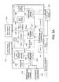
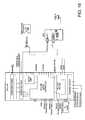
- FIG. 1is a block diagram illustrating a robotic control system in one embodiment of the present invention
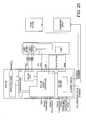
- FIG. 2is a block diagram illustrating a vehicle control systems according to one embodiment of the present invention
- FIGS. 3A-Bare block diagrams illustrating a vehicle control system according to another embodiment of the present invention.
- FIGS. 3C-Dare block diagrams illustrating another vehicle control system according to one embodiment of the present invention.
- FIG. 3Eis a block diagram illustrating a vehicle level control according to one embodiment of the present invention.
- FIG. 4is a top view of an illustrative vehicle including robotic control modules according to one embodiment of the present invention.
- FIG. 5is a top view of the illustrative vehicle of FIG. 4 including an engine and robotic control modules according to one embodiment of the present invention
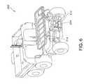
- FIG. 6is a perspective view of the vehicle of FIG. 4 including a bed according to one embodiment of the present invention.
- FIG. 7is a side view of the illustrative vehicle of FIG. 4 including a bed according to one embodiment of the present invention.
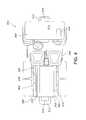
- FIG. 8is a close-up view of the engine and robotic control modules of the vehicle of FIG. 5 according to one embodiment of the present invention.
- FIG. 9is a block diagram illustrating a robotic control module in one embodiment of the present invention.
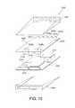
- FIG. 10is an exploded view of a robotic control module in one embodiment of the present invention.
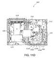
- FIGS. 11A-Dare various views of the robotic control module in FIG. 6 according to one embodiment of the present invention.
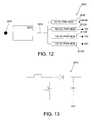
- FIG. 12is a block diagram illustrating a power system of a robotic control unit in one embodiment of the present invention.
- FIG. 13is a schematic of a booster circuit of the power system of one embodiment of the present invention.
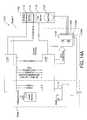
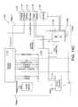
- FIG. 14Ais block diagram illustrating a motor amplifier of a robotic control unit according to one embodiment of the present invention.
- FIG. 14Bis a block diagram illustrating the motor amplifier of FIG. 14A in a brushless mode
- FIG. 14Cis a block diagram illustrating the motor amplifier of FIG. 14A in a brush mode
- FIG. 15is a schematic of a power system of the motor amplifier of FIGS. 14A-C according to one embodiment of the present invention.
- FIG. 16is a schematic of a field effect transistor circuit of the motor amplifier of FIGS. 14A-C according to one embodiment of the present invention.
- FIG. 17is a flow diagram of an illustrative software check procedure of one embodiment of the present invention.
- FIG. 18is a layout of a robotic control unit layout according to one embodiment of the present invention.
- FIG. 19is a schematic of a first robotic control unit according to one embodiment of the present invention.
- FIG. 20is a schematic of a second robotic control unit according to one embodiment of the present invention.
- FIG. 21is a schematic of a third robotic control unit according to one embodiment of the present invention.
- FIG. 22is a schematic of a fourth robotic control unit according to one embodiment of the present invention.
- FIG. 23illustrates a single board computer software architecture for a supervisory RCU according to one embodiment of the present invention
- FIG. 24illustrates a single board computer forward perception engine software architecture for an RCU according to one embodiment of the present invention
- FIG. 25illustrates a single board computer camera and steering software architecture for an RCU according to one embodiment of the present invention
- FIG. 26illustrates an RCU software architecture according to one embodiment of the present invention
- FIG. 27illustrates an RCU software architecture according to another embodiment of the present invention.
- FIG. 28illustrates a supervisory RCU software architecture according to one embodiment of the present invention
- FIG. 29illustrates a forward perception engine RCU software architecture according to one embodiment of the present invention.
- FIG. 30illustrates a forward perception engine RCU software architecture according to another embodiment of the present invention.
- FIG. 31illustrates a perception engine RCU software architecture according to one embodiment of the present invention
- FIG. 32illustrates a camera and steering RCU software architecture according to one embodiment of the present invention.
- FIG. 33illustrates a camera and steering RCU software architecture according to another embodiment of the present invention.
- Embodiments of the inventionprovide a robotic control module or robotic control unit (RCU) for use in a robotic control system, advantageously of a vehicle, including structures, systems and methods, that provide (i) a robotic control module that has multiple functional units, such as a processor, an actuator controller, an actuator amplifier, a packet network switch, and a power supply integrated into a single package/housing; (ii) a robotic control module that is packaged to reduce heat, reduce space, shield sensitive components from electro-magnetic noise; (iii) a robotic control system utilizing robotic control modules that include the same functionality allowing for interchangeability of modules; and (iv) a robotic control system that distributes the functionality and processing among a plurality of robotic control modules in a vehicle.
- RCUrobotic control module or robotic control unit
- a processortypically handles an overall supervisory role, but a local processor can also run sensor drivers and peripheral drivers, including readily available operating system (“OS”) and/or real time operating system (“RTOS”) drivers (e.g., Linux, Windows, VxWorks), as well as specific controller code for such platforms.
- OSoperating system
- RTOSreal time operating system
- a processorcan also execute data converters, e.g., video, image, audio, or other signal protocol converter or a map generator.
- a power supplycan provide appropriate, clean, conditioned power for such sensors and peripherals.
- a motor controller and amplifierare generally required for actuators—and some sensors may also require actuation (e.g., scanning sensors, gimbaled sensors).
- a DSP motor controllercan also run a CAN protocol stack, which provides the capability of CAN communications and control of standardized vehicle payloads and peripherals.
- a flexible amplifiere.g., fast, precise CPLD or other logic device control over phase, commutation
- the packet network switch or routercan channel the large amounts of data coming from cameras, laser scanners, and other sensors.
- Sensors and actuatorsmay be laid out in positions according to necessity (e.g., cameras are mounted relatively high up, radios are mounted very close to their antennas—which are preferably also as high as possible, a steering actuator on the steering column, etc.). It is advantageous to provide the above-described capabilities in a form that can be placed adjacent the sensor or actuator (e.g., minimizing noise caused by long signal paths, wiring, etc.). It can be advantageous to provide all of them in a form that can be placed adjacent to or near any sensor and/or actuator and provide everything the sensor might need (power, control, drivers, data conversion, communication); or everything that the actuator could need (modulated phase control and amplified power, communication), or everything both could need. In some cases contemplated by the invention, selected ones of these capabilities can be provided in the single location with different advantages as discussed herein, but it remains advantageous to include all of them.
- a flattened, cigar-box like unitsuch as module 500 in FIG. 11C , preferably less than 2-3 liters, e.g. 1 liter, (approximately 200 mm ⁇ 250 mm ⁇ 50 mm in +/ ⁇ 50 mm increments) may preferably house all of the listed components without active cooling.
- the circuit board arrangementsuch as the arrangement illustrated in FIGS. 11A-D , therein can be relatively tight, and balanced to arrange heat-generating and heat sensitive components to avoid one another, and also EM noise-generating, and EM noise-sensitive components to avoid one another (some of these components may be one and the same).
- Such an enclosurecan be placed strategically in idle or void spaces of a smaller vehicle (where no moving parts intrude), and can be networked within and between such spaces.
- a cigar-box enclosurewill fit between an engine and the engine compartment walls 390 , 392 , under or above flat surfaces 394 , inside vehicle doors 396 , under floor space, attached to the back of seats, in roof space, etc.
- the versatile unit as configured hereinmay be useful and advantageous even where there are no idle spaces, such as in a “vehicle” too small to carry a passenger, or when it is arranged in payload or passenger compartments.
- Certain embodiments of the present inventioncan provide identical or nearly identical versatile robotic control modules that can be placed in different locations to serve different roles, and nonetheless be arbitrarily placed in each location, exchanged with one another, or exchanged with spares from a depot, with “zero configuration” or in a “plug and play” manner.
- “Zero configuration”may be implemented here with a local code setting (e.g., resistor, jumper, etc.) at the site of placement that is read by the module and tells the module how to configure itself, i.e., according to the site (which has predetermined resources to be hooked up).
- the modulescan have the same software, and load up what is deemed necessary for the site. For example in FIG.
- RCUs 238 and 306may be removed and RCU 238 may be installed in the space provided for RCU 306 or vice versa.
- modules used hereinclude at least one processing core, chip and/or board, as well as one of motor driving circuitry (e.g., with phase modulation code and/or integrated amplifier) and/or (e.g., sensor) power supply (e.g., with driver code), and/or a network connection (e.g., switch).
- motor driving circuitrye.g., with phase modulation code and/or integrated amplifier
- sensor power supplye.g., with driver code
- a network connectione.g., switch
- a sensor modulecould omit the motor driving circuits, and still be interchangeable at sensor sites to provide computing, power supply, and network facilities at each site; an actuator module, interchangeable, could omit the external outputs of the power supply (the power supply conditions vehicle power for the internal components as well), and still be interchangeable at actuator sites.
- a sensor/motor modulecould omit one of the processor cores, although not the motor control processor core, which may be a DSP. Every module added can be added in the same manner, and can enhance the overall capability for the vehicle.
- Certain embodiments of the present inventionprovide a robotic control platform dispersing computation, motor control, and sensor/communication capabilities among networked modules. Because one advantageous implementation of the invention includes a substantially 500-1000 MIPS (millions of instructions per second, which is a rough lower limit for an autonomous supervisory processor), 1 Watt class processor in each module, each module that is added adds significant “compute.”
- the modulesdrive actuators—in a vehicle, three to five modules corresponding to actuators for, e.g., steering, braking, acceleration or throttle, forward/reverse.
- the modulesalso drive sensors and communication—in an autonomous vehicle, a number of modules for sensors and cameras for machine vision, scanning, proximity, radios, GPS, inertial, etc.
- Any module that has been placed for an actuatoris available to drive and network nearby sensors and adds computational capacity.
- One modulewhich may also drive sensors and control an actuator (but not necessarily), is a supervisory module and executes supervisory processors. Nonetheless, the computing capability of each module can be used for other processes, such as sensor drivers, motor control, signal processing, and the like.
- the distributed systemadds computational power with every added module. Higher power dissipation might also require more significant heat management, such as, but not limited to, fans, heat pipes, or otherwise, with higher cost and reduced reliability.
- the 500-1000 MIPS, 1 watt class processor(e.g., 2-4 watts as integrated in the single board computer supporting it) together with the other elements can be advantageous in this regard.
- Less computational capacityi.e., less by an order of magnitude, is insufficient for an autonomous mobile robots to execute the processes necessary to support autonomy.
- Higher power dissipatione.g., higher by an order of magnitude, can generate too much heat in each module (which dissipate a maximum of approximately 30 watts with all systems—CPU, DSP, power, motor control, motor amplification, Ethernet switch—fully occupied), and overwhelms electrical systems of most vehicles.
- each module that is added at an appropriate sitee.g., sensor, communication, or actuator site or node adds significant computational power.
- replacing the primary core in the disclosed module with a Pentium M class server-type processorcould increase computational power, but would dissipate more power by an order of magnitude (likely 10-30 or more watts), and would overheat the enclosure with all components active.
- the selection of the appropriate upper limit on power dissipation for the processor and single board computer(approximately 1 watt for the processor alone, exceeding this by an order of magnitude being unacceptable), limited by the lower limit on necessary computational cycles for autonomous operation of a vehicle (approximately 500-1000 MIPS for the processor alone, less than this by an order of magnitude being unacceptable), further limited by the presence of the other functional components (which are heat sensitive, and, especially the motor amplifier and power supply, generate heat), is part of the invention described herein.
- Other highly efficient componentswere also provided to the modules, as disclosed herein, and provided incremental power efficiencies leading to the maximum of 30 watts dissipated by the module from its 2-3 liters of volume.
- added computational powercan be provided with an additional independent module placed at an appropriate site (e.g., sensor, communication, or actuator site or node), and is added beneficially whenever an actuator is supported.
- a robotic control modulecan contain one or more of a processor and associated memory, such as a single board computer with a microprocessor, a network switch, such as an Ethernet switch, an actuator controller, such as a reprogrammable motor controller, an actuator amplifier, such as a motor amplifier, and a power supply within a single mountable housing.
- a processor and associated memorysuch as a single board computer with a microprocessor, a network switch, such as an Ethernet switch, an actuator controller, such as a reprogrammable motor controller, an actuator amplifier, such as a motor amplifier, and a power supply within a single mountable housing.
- FIG. 9is a block diagram of an illustrative robotics control module 400 (sometimes referred to as a Robotic Control Unit or RCU) according to one embodiment of the present invention.
- FIGS. 18-22include additional examples of various embodiments of RCUs, including a supervisory RCU illustrated in FIG. 19 and additional RCUs that perform various functions illustrated in FIG. 20-22 .
- the robotics control module 400is contained in a single housing.
- the robotics control module 400 shown in FIG. 9is divided into a top housing 402 and a bottom housing 404 . Other suitable configurations are possible.
- the bottom housing 404contains a multi-port network switch 406 , high-speed packet network ports 408 , a motor amplifier 410 , and a motor connector 412 .
- the top housing 402contains a motor controller 414 , a single board computer 416 , a power supply 418 , protocol transceivers 420 , Digital Input/Output (DIO) Buffers 422 , power switches 424 , and a multi-pin connector 426 .
- the robotic control modulemay also contain a serial bus 430 and a serial connector 428 .
- the serial bus 430can be connected to the single board computer 416 .
- the serial bus 430is a Universal Serial Bus (USB) and the serial connector 428 is a USB connector.
- USBUniversal Serial Bus
- the Single Board Computer (SBC) 416includes an embedded Central Processing Unit (CPU) and associated memory, such as, for example, Random Access Memory (RAM) and/or nonvolatile memory. Examples of SBC software architecture are illustrated in FIGS. 23-33 .
- the SBC 416is a Motorola MPC5200 PowerPC 400 MHz single board computer with the approximate dimensions of 2.5 inches by 4 inches.
- the SBC 416may include 128 MB DDR RAM and 64 MB Flash memory.
- the SBC 416may send signals to and receive signals from the protocol transceivers 420 , the DIO buffer 422 , and the switch 406 .
- the protocol transceivers 420may send and receive CAN, RS232, RS422, USB signals.
- “protocol transceivers”means transceivers that are controlled pursuant to predetermined rules for communications (e.g., packet contents, handshaking, addressing). All of CAN bus, RS-232, RS-422, and USB are well-known communications protocols for different uses—respectively for automotive control, generic serial, longer distance serial for instrumentation, and peripheral bus purposes.
- Protocol transceiverscan be added to implement different desired communications, including, but not limited to, RS-485, IEEE-488, IEEE-1394 (Firewire 400), Firewire 800, Bluetooth, USB 2.0, Wireless USB, FDDI, Fibre Channel, MIL-STD-1553 wired databus and variations such as EBR 1553 (including proprietary versions) or MIl-STD-1553C, AFDX, MMSI, ARINC 429, ATM, WIN-T, wave-division multiplexed optical fiber, SCSI of any kind, PCI & PCI Express (and other switched fabrics), SATA (serial ATA), proprietary and purpose-built rule sets, and modifications or successors to any of these.
- the DIO Buffer 422can send and receive digital and analog signals.
- the SBC 416sends and receives signals from a Digital Signal Processor (DSP) located in the motor controller 414 via RS-232 protocol.
- DSPDigital Signal Processor
- the multi-pin connector 426is a 60 pin Cinch connector.
- the power supply 418 , protocol transceivers 420 , DIO Buffers 422 , and the power switchesare connected to the multi-pin connector 426 .
- Each of these componentscan receive inputs from the multi-pin connector 426 and provide outputs to the multi-pin connector 426 .
- the power switchesare not necessarily used, but can control external power lines, switching the supply of power via such lines on and off. That is, an external power line is routed into and out of a power switch on the RCU, and the RCU can control the switch as part of its general functionality.
- Executable codemay be stored in memory of the SBC 416 that can be executed by the CPU to enable the SBC to execute and arbitrate among robotic control behaviors.
- Each robotic control module in the robotic control systemmay be provided with multiple executable code parts for different modular roles within the control system.
- each robotic control modulecan include executable code for supervisory role, for actuator control, for sensor monitoring, etc.
- the robotic control modulescan be configurable to execute only a selected portion of the executable code appropriate for the role of the particular robotic control module. Examples of the parts of the executable code can be behavior arbitration code, behavior code, sensor driver code, drive controller code, actuator controller code, database management code, database data, and data converter code.
- Each robotic control modulecan determine the function or role they will perform and what executable code they will perform based on location, connections, or other suitable methods as described above. This provides for the interchangeability of the robotic control modules.
- FIGS. 23-33illustrate embodiments of SBC software architecture for selected robotic control units.
- One embodiment of an SBC 1900 for a supervisory robotic control unitis shown as a high level block diagram in FIG. 23 .
- the supervisory SBC 1900includes a processor 1902 and network connection 1904 .
- the network connection 1904may be one or more network connections. Examples of such network connections 1904 include Ethernet TCP/IP, USB, and CAN connection such as J1939.
- the network connections 1904are adapted to connect with a plurality of devices outside of supervisory SBC 1900 , such that the supervisory SBC 1900 can receive and send a plurality of types of data and/or control signals.
- the supervisory RCUmay also include a computer-readable medium, such as memory 1906 .
- Memory 1906may any type of memory. Examples of memory 1906 include random access memory (“RAM”), read-only memory (“ROM”), optical storage, and magnetic storage. Memory 1906 may include a data storage and/or persistent data storage to store various received or computed data and executable code.
- executable-codeexamples include an operating system (not shown), such as for example BlueCat Linux or DSP basic input/output system (BIOS), a data transport (not shown) that includes software, such as for example iRobot AwareTM, to assist in the supervisory SBC 1900 communicating with outside devices, and/or applications 1908 .
- the applications 1908can include one or more supervisory RCU functional code and drive behaviors.
- the applications 1908may include configuration code 1910 that reads configuration files from storage, such as persistent storage, and puts these values into appropriate locations in the data transport.
- the applications 1908may also include an obstacle map, detection and/or avoidance code 1912 , teleoperation code 1914 , follow mode 1916 , waypoint navigation code 1918 , drive arbiter 1920 , data logging code 1922 , path playback code 1924 , telemetry code 1926 , dashboard display control 1928 , version upgrade manager 1930 , and vehicle control unit (VCU) interface 1932 .
- Embodiments of the applications 1908are described in more detail below with regard to FIGS. 26-33 .
- FIG. 24illustrates one embodiment of software architecture for a forward perception engine SBC 2000 included on a second RCU.
- the forward perception engineincludes a processor 2002 and network connection 2004 .
- the network connectionmay include one or more different types of network connections, as described above, that are adapted to receive and send data over one or more networks.
- the forward perception engine SBC 2000may also include a readable medium, such as memory 2006 .
- Memory 2006may any type of memory and may include a data storage and/or persistent data storage to store various received or computed data and executable code.
- the applications 2008can include a variety of software code and behavior code.
- the applications 2008can include a laser scanner driver 2010 , a nodding motion controller 2012 , and a three-dimensional map generator 2014 .
- Embodiments of a laser scanner driver, nodding motion controller, and three-dimensional map generatorare described in more detail below.
- Embodiments of the present inventionmay also include a third RCU having an SBC that includes a rear perception engine (not shown).
- the rear perception enginecan include a laser scanner driver that reads configuration data, configurations the laser scanner for continuous output of range data, reads range data, and publishes the data to a network message queue for use by a supervisory RCU.
- the rear perception enginemay include similar or the same behavior code, architecture, or otherwise, or the forward perception engine.
- FIG. 25illustrates one embodiment of a fourth RCU that can be a camera and steering RCU including an SBC 2100 .
- the camera and steering SBC 2100may include a processor 2102 and one or more network connections 2104 .
- the network connections 2104can send and receive data over a network to other devices or other RCUs.
- the camera and steering SBC 2100may also include a readable medium, such as memory 2106 .
- Memory 2106may any type of memory and include a data storage and/or persistent data storage to store various received or computed data and executable code.
- An example of such executable codeincludes applications 2108 that include one or more software programs and/or behavior code. Examples of such programs or code include a drive camera controller 2110 , a video format converter 2112 , and a steering actuator control 2114 . Embodiments of a drive camera controller, video format converter, and steering actuator control are described in more detail below.
- RCUsmay be provided having a software architecture that includes a application layer with a one or more applications and types of applications.
- RCUsmay include only one application, while other RCUs are configured include more than one application.
- the applicationsmay be uploaded to the RCUs.
- FIGS. 26-27illustrate embodiments of a robotic level controller and including one or more application types and network connections.
- FIG. 26illustrates a software architecture for a robotic level controller 2800 that includes a application layer 2802 that can include one or application types. Examples of such application types include behavioral control 2803 , peripheral communications and control 2805 , and databases 2807 .
- the behavioral control 2803may include applications such as robotic control behaviors, monitors, and/or arbiters.
- the peripheral communications and control 2805may include sensor drive code, protocol transceiver monitoring code, camera communications, control unit interfaces, and telemetry.
- Databases 2807may include image, map, and waypoint databases.
- the RCU software architecture 2800may also include a data transport layer 2804 and an operating system layer 2806 .
- the operating system layer 2806may include an operating system, such as a Linux operating system, or any type of signal processing code.
- a data storage/network connection layer 2808may also be included.
- the data storage/network connection layer 2808may include data storage, such as persistent data storage 2810 and one or more network connections, such as digital 2812 , CAN 2814 , USB 2816 , Ethernet 2818 , and serial 2820 .
- the network connectionsmay receive a plurality of data and types of data 2822 and output a plurality of data and types of data 2824 .
- FIG. 27illustrates another embodiment of a robotic level controller software architecture 2900 that can include an application layer 2902 that includes one or more application types having one or more applications.
- the application layer 2902may include actuator control application types 2903 and/or alternative signal processing 2905 .
- the actuator control 2903may include motor controls for brush motors, motor controls for brushless motors, motor control for other actuators, and/or other motor control code.
- the alternative signal processing 2905may include DSP signal processing code, and/or CPLD signal processing code.
- the RCU softwaremay also include a DSP operating system layer 2904 that can include a DSP BIOS or other option operating system.
- An example of a DSP BIOSincludes Texas InstrumentsTM DSP BIOS.
- the RCU 2900can include a network connection layer 2906 that includes one or more network connectors, such as digital 2908 , encoders 2910 , Hall effects 2912 , CAN 2914 , analog 2916 , serial 2918 , USB, 2920 , Ethernet 2922 , and motor phases 2924 .
- the network connectorscan receive various types of data 2926 and output various types of data 2928 .
- FIGS. 28-33illustrate particular embodiments of RCU software architecture, including architecture associated with applications, data transport, and physical layer arrangements associated with different exemplary configurations.
- the embodiments of RCU software architecture described hereinare RCU having particular applications and perform certain functions that may be determined when the RCU is designated as such and includes the appropriate applications or executable code.
- the RCUsmay be devices with the same electronic and physical configuration, but may have the same or different software loads.
- the RCUmay become a supervisory RCU after being designated as such and receiving the appropriate applications.
- the RCU software architecture 2200can include one or more layers.
- the layersmay include an application layer 2202 that includes computer-executable code, such as applications, a data transport layer 2204 that includes executable code, such as for example iRobot AwareTM, to assist in the RCU communicating with outside devices, and/or applications on the application layer 2202 , an operating system layer 2206 that includes an operating system such as BlueCat Linux, and a data storage/network connection layer 2208 that can send an receive data from other devices and store data.
- the data storage/network connection layer 2208may include a data storage, such as a persistent data storage 2210 .
- the data storage/network connections layer 2208may include one or more network connections adapted to connect with a plurality of devices outside of the RCU and send and receive data or control signals.
- the network connectionsmay include a CAN connection 2212 , such as a J1939 connector, a USB connector 2214 , and an Ethernet connector 2216 .
- the network connectorsmay receive a plurality of data 2218 or send a plurality of data 2220 .
- Examples of Ethernet data 2222 received by the Ethernet connectorinclude laser scanner range data, GPS position data, compass orientation data, teleoperation commands from a remote operator control unit (OCU), dashboard display status and input, and software upgrades.
- An example of USB data 2224also includes software upgrades.
- Examples of CAN data 2226includes vehicle status information, vehicle mode switch, and diagnostic commands from CAN diagnostic ports.
- Examples of transmitted Ethernet data 2228includes telemetry data to a remote OCU, dashboard display instructions, and software updates to other RCUs.
- An example of transmitted USB data 2230includes files.
- Examples of transmitted CAN data 2232includes drive commands to a supervisory VCU and diagnostic responses to CAN diagnostic port.
- the application layer 2202can include one or more applications, such as RCU functional code and drive behaviors.
- the applicationsmay include configuration code 2201 that reads configuration files from storage, such as persistent storage, and puts these values into appropriate locations in the data transport.
- the applicationsmay also include an obstacle map and detection 2203 .
- the obstacle map and detection codecan receive input range and odometry data and construct a two-dimensional obstacle map.
- Other applicationscan include teleoperation code 2205 that receives input commands from a remote OCU and outputs a trajectory set for use by a drive arbiter 2211 and several discrete values and a follow mode or semi-autonomous mode 2207 that receives obstacle data from the obstacle map to locate a target or object to follow and outputs trajectory sets for use by the drive arbiter 2211 .
- Waypoint navigation code 2209may also be included that can receive input waypoint values from a chosen path an output a trajectory set for use by the drive arbiter 2211 .
- the drive arbiter 2211may be included with the applications to receive input trajectory sets and priorities from various drive behaviors, obstacle data form the obstacle map and configuration data from various configuration publications.
- the drive arbiter 2211may also output selected trajectory data to actuators or other devices outside of the RCU.
- the applicationsmay also include data logging code 2213 that can receive status data from vehicle sensors and writes data to a data storage, such as persistent data storage 2210 . After receiving an operator command, the data logging code 2213 can copy data wirelessly or on a wireline to an OCU or removable data storage device.
- the applicationsmay also include path record 2215 and path playback 2217 code.
- the path record code 2215can receive location data from vehicle sensors and inputs from an operator and write the data, such as representations of path waypoints, to data storage, such as persistent data storage.
- the path playback code 2217can receive a path as designated by an operator and play the waypoints included with that path to waypoint navigation.
- the applicationsmay also include telemetry code 2219 that can receive status data from vehicle sensors and sends packets to a remote OCU.
- a dashboard display control 2221may also be included that can receive status data from vehicle sensors and inputs from a dashboard display and send display instructions to the dashboard display.
- the applicationsmay also include a version upgrade manager 2223 and VCU interface 2225 .
- the version upgrade manager 2223can receive software upgrades and distribute the software upgrades throughout other RCUs.
- the VCU interface 2225can receive driving and diagnostic commands and send driving commands to the VCU via appropriate CAN messages and sends diagnostic messages to other RCUs and returns their reports to the VCU.
- Obstacle avoidance code 2227may also be included.
- the obstacle avoidance code 2227can receive input trajectories from the drive arbiter 2211 and obstacle data from the two-dimensional obstacle map and scores these trajectories according to obstacle avoidance rules.
- FIG. 29illustrates one embodiment of software architecture for a forward perception engine RCU 2 2300 .
- the RCUmay become a forward perception engine RCU after being designated as such and receiving the appropriate applications.
- the forward perception engine RCU 2 software architecture 2300may include one or more software layers.
- the layersmay include an application layer 2302 that includes computer-executable code, such as applications, a data transport layer 2304 that includes executable code, such as for example iRobot AwareTM, to assist communicating with outside devices, and/or applications on the application layer 2302 , an operating system layer 2306 that includes an operating system such as BlueCat Linux, and a data storage/network connection layer 2308 that can send an receive data from other devices and store data.
- the data storage/network connection layer 2308may include a data storage, such as a persistent data storage 2310 .
- the data storage/network connections layer 2308may include one or more network connections adapted to connect with a plurality of devices outside of the RCU and send and receive data or control signals.
- the network connectionsmay include a CAN connection 2312 , such as a J1939 connector, a digital connector 2314 , an Ethernet connector 2316 , and a Serial connector 2318 , such as an RS232 or RS 422 connector.
- the network connectorsmay be used to receive a plurality of data 2320 or send a plurality of data 2322 .
- Examples of Serial data 2324 received by the serial connector 2218include messages from a laser scanner, such as LMS291, and elevation messages from a nodding motion controller board.
- An example of Ethernet data 2326includes scan control commands.
- An example digital data 2328includes horizontal sync pulse data from an LMS291 laser scanner.
- An example of CAN data 2330includes elevation messages from a nodding motion controller board.
- Examples of transmitted serial data 2332includes commands to a laser scanner, such as LMS291, and motion control commands, such as to a nodding motion controller board.
- An example of Ethernet data 2334includes range data to another RCU, such a via a message queue.
- An example of transmitted CAN data 2336includes motion control commands, such as a nodding motion controller board.
- the application layer 2302can include one or more applications, such as RCU functional code and drive behaviors.
- the applicationscan include a laser scanner driver, such as LMS291 driver 2301 , a nodding motion controller 2303 , and a three-dimensional map generator 2305 .
- the LMS291 driver 2301may read configuration data that configures a laser scanner, such as for example LMS 291, for continuous output of range data at a particular frequency.
- a laser scannersuch as for example LMS 291
- the LMS291 driver 2301may also read range data and timestamp it and publish the data to a network message queue for use by a three-dimensional map generator.
- the nodding motion controller 2303can read configuration data, receive commands to control nodding/scanning behavior, and manipulate the scanning hardware according to the preceding commands.
- the nodding motion controller 2303may also receive horizontal sync pulses as an interrupt and notes the time of the last interrupt.
- the nodding motion controller 2303can receive elevation messages from a nodding motion controller board, compute the time of the start of the last scan based on empirically determined fixed offset from horizontal sync pulses, uses this time to timestamp the elevation data, and sends time stamped elevation data to the three-dimensional map generator 2305 .
- the three-dimensional map generator 2305can read configuration data, read scans from the laser scanner driver 2305 , read time stamped elevation messages from the nodding motion controller 2303 , and compute the elevation of the nodding mechanism at the start of the last range scan based on, for example, sinusoidal motion of the nodder.
- the three-dimensional map generator 2305may also mark each scan with computed elevation at the start of the scan, publish range data annotated with elevation information to a network message queue for use by a supervisory RCU, and detect a loss of synchronization due to errors and resynchronize by discarding data until a match can be achieved between all timestamps.
- FIG. 30illustrates a second embodiment of software architecture for a forward perception engine RCU 2400 .
- the software architecture 2400includes a plurality of software layers.
- the layersmay include an application layer 2402 having applications, a DSP BIOS layer or optional operating system layer 2404 that can include an operating system or other signal processing code, and a network connection layer 2406 .
- An example of an operating system including on the DSP operating system layer 2404includes a Texas InstrumentsTM DSP BIOS.
- the network connection layer 2406may include one or more network connectors, such as a digital input and output 2408 , encoder connector 2410 , hall effect connector 2412 , CAN connector 2414 , such as a J1939 connector, analog input 2416 , serial connector 2418 , such as an RS232 or RS422 connector, and motor phases output 2420 .
- the network connectorsmay be used to receive a plurality of data 2428 or send a plurality of data 2430 .
- Examples of serial data 2432 received by the serial connector 2418include identification from other RCUs and a command line interface.
- An example of received CAN data 2434includes J1939 messages.
- An example of received hall effects 2436includes a commutation from Hall effect sensors on motor shafts.
- An example of receive encoder data 2438includes incremental encoder data on a nodding mechanism.
- An example of received digital data 2440includes a sync pulse from a laser scanner, such as an LMS291 laser scanner.
- An example of transmitted CAN data 2442includes J1939 messages.
- An example of motor phase data 2444includes three-phase motor phases A, B, and C.
- Application on the application layer 2402may include a nodding motion motor control 2401 .
- the nodding motion motor control 2401may communicate with a laser nodding actuator or other device using a J1939 protocol and through a CAN bus.
- the nodding motion motor controlmay also provide command line debug via the same or different network connection.
- FIG. 31illustrates one embodiment of software architecture for a rear perception engine RCU 3 2500 .
- the RCUmay become a rear perception engine RCU after being designated as such and receiving the appropriate application code.
- the rear perception engine software architecturecan also include a plurality of software layers, such as an application layer 2502 that includes one or more applications, a data transport layer 2504 , an operating system layer 2506 that can include an operating system, such as BlueCat Linux, and a data storage/network connect layer 2508 .
- the data storage/network connect layer 2508can include a data storage, such as persistent data storage 2510 , and one or more network connectors to allow the RCU to send and receive data and other communicate with devices outside of the RCU.
- the network connectorscan include CAN 2512 , USB 2514 , Ethernet 2516 , and Serial 2518 .
- the network connectorscan receive various types of data 2528 and output various types of data 2530 .
- the application layer 2502may include a laser scanner driver application, such as LMS291 driver 2501 , that reads configuration data, configurations the laser scanner for continuous output of range data, reads range data, and publishes the data to a network message queue for use by a supervisory RCU.
- the application layer 2502may include similar or the same behavior code, architecture, or otherwise, as the forward perception engine.
- FIG. 32illustrates one embodiment of a software architecture for a camera and steering RCU 4 2600 .
- the camera and steering software architecture 2600may include a plurality of software layers such as application layer 2602 that can include one or more applications, a data transport layer 2604 , operating system layer 2606 that can include an operating system, such as BlueCat Linux, and data storage/network connection layer 2608 .
- the data storage/network connection layer 2608can include a data storage, such as persistent data storage 2612 , and one or more network connectors for sending and receiving data.
- the network connectorscan include digital outputs 2610 , CAN 2614 , USB 2616 , Ethernet 2618 , and Serial 2620 .
- Examples of data received 2632 by the RCUincludes video from drive cameras, drive camera selection commands, software upgrades and updates, and an identification from other RCUs.
- Examples of data transmitted 2634 by the RCUcan include the RCU's identification, video to an OCU, commands to drive cameras, and camera power control.
- the application layer 2602may include one or more applications, such as drive camera controller 2601 and video format converter 2603 .
- the drive camera controller 2601can configure a drive camera based on configuration data and commands received over a network, select active drive camera based on commands, disable output from inactive cameras to reduce network load, and/or switch camera power on and off.
- the video format converter 2603may read video, such as MJPEG video, from the active drive camera, convert MJPEG video into a subset format, and multicast video stream in the subset format to an OCU.
- FIG. 33illustrates another embodiment of software architecture for a camera and steering RCU 4 2700 .
- the camera and steering software architecture 2700can include a plurality of software layers, such as application layer 2702 , a DSP operating system layer 2704 , and network connection layer 2706 .
- the DSP operating system layer 2704may include an DSP BIOS or optional operating system.
- the network connection layer 2706may include one or more types of network connectors, such as digital inputs 2708 , encoders 2710 , Hall effects 2712 , CAN 2714 , analog inputs 2716 , serial 2718 , and motor phases A, B, C 2720 that can be used to receive data 2728 and output data 2730 .
- the application layer 2702may include one or more applications.
- the applicationsmay include a steering actuator control application 2701 .
- the steering actuator control 2701can provide command line debug over a first network connector, such as RS232 and communicate with one or more outside devices, such as actuators, over a second network connector, such as a CAN connector using J1939 protocol.
- FIG. 9illustrates a block diagram of an embodiment of a robotic control module 400 .
- the robotic control module or RCU 400has four high speed packet network ports 408 , which are connected internal to the module 400 to the multi-port network switch 406 .
- the ports 408are externally connected to a packet network that is capable of relaying instructions for the reprogrammable actuator controller.
- the packet network usedis Ethernet and the ports 408 are Ethernet ports and the switch 406 is an Ethernet switch. For example, Ethernet packets from other robotic control modules, sensors, or other devices are received at the ports 408 . These packets are processed by the switch 406 . If a packet is intended for another device on the network, the switch routes the packet to the device.
- switch 406passes the packet to the SBC 416 .
- the switch 408receives outgoing packets from the SBC 416 and routes them to their destination.
- the switch 408can perform all necessary authentication and confirmation routines and messages required by the network.
- the power supply 418is capable of receiving vehicle power and outputting a variety of regulated voltages.
- the input vehicle powermay be from 8V to 36V DC and be unregulated.
- the vehicle powermay be from an alternator on the vehicle and is thus unregulated and subject to power spikes, power drops, and in-rush currents, in the general range of 8-36V.
- the power supply 418receives the unregulated vehicle power from the multi-pin connector 426 and outputs 5V, 12V, and 24V power.
- the power supplyincludes a first stage that can convert and condition the unregulated power into a regulated first level voltage and a second stage that can covert the first level voltage into multiple level voltages.
- the power supplyincludes one stage that coverts and conditions the unregulated power into multiple level voltages.
- the 5V poweris used internal to the robotic control module to power the SBC 416 , motor controller 414 , and the switch 406 .
- the 5V powermay be made available exterior to the robotic control module 400 .
- the robotic control module 400can, in one embodiment, make the 12V and 24V power available external to the robotic control module 400 via the multi-pin connector 426 .
- the motor amplifier 410receives vehicle power from the motor connector 412 and outputs three phase DC power to control an associated actuator, such as a motor.
- the motor amplifiercan provide power to control DC brushless motors and DC brushed motors. In one embodiment, the motor amplifier can provide sufficient power to control an AC motor. In some embodiments, a plurality of motor amplifiers may be used, where each provides power to a single associated actuator. Different motor amplifiers may also be used to provide different levels of DC power.
- the motor amplifier 410provides the actuator or motor power via the motor connector 412 .
- the motor connector 412is a Deutsch Connector.
- An Emergency Stop (E-Stop) systemmay be placed on the input vehicle power to the motor connector 412 . This configuration provides that activation of an E-Stop removes power to the motor amplifier and the actuators, but power supplied by the power supply 418 to the SBC 416 , and other components remains intact.
- E-StopEmergency Stop
- the motor amplifier 410is controlled by signals received from the motor controller 414 .
- Some embodiments of the motor controllerinclude digital inputs and outputs and analog inputs.
- the motor controller 414can receive inputs, such as robotic control behaviors, from the SBC 416 , buffers 422 , or other SBC's (e.g., in other RCU's) and process these inputs to generate control signals to send to the motor amplifier 410 .
- the motor controller 414may receive analog inputs, such as voltage monitors at different levels, such as 24, 5, 3.3, 2.654, and 1.5 volts, temperature monitors of the motor amplifier 410 and board temperatures, current monitor signals regarding torque feedback, potentiometer readings used to control steering position, and RCU identifications used to identify the type of RCU and enable specific functionality, such as steering and nodding control.
- analog inputssuch as voltage monitors at different levels, such as 24, 5, 3.3, 2.654, and 1.5 volts
- temperature monitors of the motor amplifier 410 and board temperaturessuch as 24, 5, 3.3, 2.654, and 1.5 volts
- current monitor signals regarding torque feedbacksuch as potentiometer readings used to control steering position
- RCU identificationsused to identify the type of RCU and enable specific functionality, such as steering and nodding control.
- the motor controller 414may also receive digital inputs, such as encoder inputs for nodding control, synchronization pulses for synchronizing laser data acquisition, signals used to configure the motor amplifier 410 , signals used to communicate with the SBC 416 , such as to provide user command line interface and to read compass data, CAN data used as a communication interface and physical layer for J1939 protocol, and motor amplifier fault signals that can trigger an interrupt as detected.
- the motor controller 414may output digital signals such as PWM signals used to control motor torque, motor amplifier outputs, motor direction control, and an LED signal used as an indicator. Some embodiments of the motor controller 414 use a J1939 protocol communication standard based on a CAN physical interface.
- Data received and transmitted by the CAN interfacemay be periodically read, written, and stored into priority queues for processing by a J1939 stack.
- the J1939 stackcan process incoming data by executing a callback function associated with incoming message data.
- the applicationcan call an appropriate function for outgoing data based on the message to be sent.
- the datais then processed by the J1939 stack and placed on the transmit queue.
- the motor controller 414may also use an RS232 physical interface.
- the signals to and from the motor controller 414may be processed by peripherals, such as DSP peripherals.
- Analog inputs and one or more digital inputsmay be processed by an application based on polling or interrupt handling.
- the motor controller 414contains a Digital Signal Processor (DSP).
- DSPDigital Signal Processor
- the motor controllercan include a programmable logic device or a gate array.
- the motor controller DSPmay boot application software, perform diagnostics, perform online software updates, set and configure motor controller and motor amplifier modules, determine RCU identification, perform position, velocity, and current control functions, read sensors, monitor system health, provide user with command line interface for configuration and testing.
- the robotic control modulemay include a mountable housing (e.g., module 500 formed from housings 502 - 504 ), a reprogrammable actuator controller (e.g., motor controller and/or DSP 414 ) within the mountable housing, an actuator connector (e.g., connector 412 ) available on the exterior of the mountable housing communicating a signal for actuator driving that is modulated by the reprogrammable actuator controller, a packet network switch (e.g., switch 406 , such as an Ethernet switch or router) within the mountable housing, each of a plurality of network connectors (e.g., connectors or ports 408 ) available on the exterior of the mountable module being capable of connection to a packet network and communicating with the packet network switch, the packet network being capable of relaying instructions for the reprogrammable actuator controller, and a power supply (e.g., power supply 418 ) within the mountable housing, the power supply receiving unregulated power from the mobile robotic platform through a power input to the mountable housing (in this
- a robotic control moduleincludes a mountable housing 404 , a reprogrammable actuator controller 414 within the mountable housing capable of issuing actuator control signals within the mountable housing, an actuator amplifier (e.g., motor amplifier 410 ) within the mountable housing 404 that receives the actuator control signal from the reprogrammable actuator controller 414 , an actuator connector 412 available on the exterior of the mountable housing (e.g. multipin connector 426 ) communicating an actuator drive signal modulated by the reprogrammable actuator controller 414 and the actuator amplifier (e.g.
- a packet network switch 406 within the mountable housingeach of a plurality of network connectors 408 available on the exterior of the mountable housing being capable of connection to a packet network and communicating with the packet network switch 406 , the packet network being capable of relaying instructions for the reprogrammable actuator controller 414 , and a power supply 418 within the mountable housing 404 , the power supply receiving unregulated power from the vehicle through a power input (e.g. 426 ) to the mountable housing 404 and converting the unregulated power into interior regulated power for the packet network switch 406 and the reprogrammable actuator controller 414 and into exterior regulated power, a power supply connector (e.g. 426 ) available on the exterior of the mountable housing being capable of connection to the exterior regulated power.
- a power inpute.g. 426
- a robotic control module 400includes a mountable housing 404 , a microprocessor board 416 with code execution dynamic memory (e.g., RAM) and code storage nonvolatile memory (e.g., flash) within the mountable housing 404 , the microprocessor board 416 being capable of executing and arbitrating among robotic control behaviors, a reprogrammable actuator controller 414 within the mountable housing 404 capable of issuing actuator control signals within the mountable housing according to the robotic control behaviors, an actuator amplifier (e.g.
- an actuator connector 412available on the exterior of the mountable module communicating an actuator drive signal modulated by the reprogrammable actuator controller 414 and the actuator amplifier (e.g.
- a packet network switch 406 within the mountable module 404each of a plurality of network connectors 408 available on the exterior of the mountable module being capable of connection to a packet network and communicating with the packet network switch 406 , the packet network being capable of relaying instructions for the reprogrammable actuator controller 414 , and a power supply 418 within the mountable module 404 , the power supply 418 receiving unregulated power from the mobile robotic platform through a power input (e.g. 426 ) to the mountable module 404 and converting the unregulated power into interior regulated power for the microprocessor board, the reprogrammable actuator controller 414 , and the packet network switch 406 and into exterior regulated power, a power supply connector (e.g. 426 ) available on the exterior of the mountable module being capable of connection to the exterior regulated power.
- a power supply connectore.g. 426
- a robotic control module 400includes a mountable housing 404 , a microprocessor board 416 with code execution dynamic memory and code storage nonvolatile memory within the mountable housing 404 , the microprocessor board 416 further including a plurality of protocol transceivers 420 (e.g., RS-232, -422; CAN bus) and being capable of executing transceiver monitoring code (e.g., protocol stacks or drivers), a multi-pin connector 426 available on the exterior of the mountable housing being capable of communicating with the plurality of protocol transceivers (e.g., to connect sensors or the like), a reprogrammable actuator controller 414 within the mountable module capable of issuing actuator control signals within the mountable housing 404 , an actuator amplifier (e.g.
- the motor amplifier 410within the mountable housing 404 that receives the actuator control signal from the reprogrammable actuator controller 414 , an actuator connector 412 available on the exterior of the mountable housing 404 communicating an actuator drive signal modulated by the reprogrammable actuator controller 414 and the actuator amplifier 410 , a packet network switch 406 within the mountable housing 404 , each of a plurality of network connectors 408 available on the exterior of the mountable housing 404 being capable of connection to a packet network and communicating with the packet network switch 406 , the packet network being capable of relaying instructions for the reprogrammable actuator controller 414 , and a power supply 418 within the mountable housing 404 , the power supply 418 receiving unregulated power from the vehicle through a power input (e.g.
- a power supply connector(e.g. 426 ) available on the exterior of the mountable housing being capable of connection to the exterior regulated power.
- a distributed robotic control system for a robotic vehicle or mobile platformincludes a robot platform having a body (e.g., as shown in FIGS.
- each interchangeable mountable moduleincluding a power input (e.g., optionally via multipin connector 426 ), a plurality of network connectors (e.g., ports 408 ), and a multi-pin connector (e.g., 426 ) available on the exterior of the interchangeable mountable module, and each interchangeable mountable module including: a microprocessor board 416 with code execution dynamic memory (e.g., SDRAM) the microprocessor board 416 further includes: a plurality of protocol transceivers 420 , the multi-pin connector 426 being capable of communicating with the plurality of protocol transceivers sensors, and nonvolatile memory including executable code
- the robotic control systemincludes versatile robotic control modules (sometimes referred to herein as Robotic Control Units (RCU)) that may be used to control the operation systems, such as a throttle system, a steering system, a braking system, and a shifting system.
- RCURobotic Control Unit
- the robotic control modulesare distributed throughout the vehicle in idle spaces in the vehicle. Idle spaces can exist void spaces that are unused on the vehicle prior to installation of the robotic control system (as shown in FIGS. 4-8 ).
- the robotic control modulesmay each have different functions. For example, one robotic control module may control an operation system (i.e., a system for operation of a vehicle) and another robotic control module may perform supervisory functions. In one embodiment, each robotic control module is capable of performing any of the different functions depending on its placement in the vehicle.
- robotic control packaging for a mobile robotic platformincludes a housing 500 formed as a flat rectangular prism of six face panels, front and rear faces of the housing being defined on the smallest surface panels of the six surface panels, a first circuit board arranged within the housing 508 , extending from the front face to the rear face, the first circuit board including a signal processor 512 sensitive to electromagnetic noise arranged toward the front face of the housing, a second circuit board 506 arranged within the housing parallel to the first circuit board 508 , extending from the front face to the rear face, the second circuit board 506 including a motor amplifier inductor 516 and a power supply inductor 514 both arranged toward the rear face of the housing 500 and both generating electromagnetic noise, and a third circuit board 510 arranged within the
- the first circuit board 508 and the second circuit board 506may define there between a flat intermediate volume, each of the motor amplifier inductor 514 , power supply inductor 516 , and third circuit board 510 , and at least some components of the first circuit board 508 and of the second circuit board 506 extend into the flat intermediate volume by an amount such that such components of the first circuit board 508 and second circuit board 506 overlap within the flat intermediate volume.
- the robotic controller packaging for a mobile robotic platformmay further be configured such that the housing 500 is made from heat conductive material; the first circuit board 508 includes power supply circuitry generating internal heat connected to the housing 500 via a direct heat conductive path 520 ; and the second circuit board 506 includes motor amplifier circuitry generating internal heat connected to the module via a direct heat conductive path 518 , so that the housing 500 acts as a heat sink for each of the power supply circuitry and the motor amplifier circuitry.
- the motor amplifier circuitry generating internal heatmay include a plurality of MOSFETs, and such MOSFETs can be each arranged to directly contact the housing connected to the housing so that the housing acts as a heat sink for the plurality of MOSFETs.
- An embodiment of the present inventionincludes a method of fitting an existing mobile platform with robotic control packaging and includes forming a plurality of mountable modules as flat rectangular prisms of six face panels, front and rear faces of each mountable module being defined on the smallest surface panels of the six surface panels, the front and rear faces having distributed between them a power input, an actuator connector, a plurality of network connectors 524 A-D, and a power supply connector 522 ; selecting a plurality of mounting sites for the plurality of mountable modules on the existing mobile platform, at least some of the mounting sites being idle space within interior compartments of the existing mobile platform through which no moving part passes; mounting a plurality of the mountable modules within the mounting sites; connecting all of the mountable modules to form a communications network among the network connectors; connecting all of the mountable modules via the power input to a power source of the existing mobile platform; connecting selected ones of the mountable modules to a corresponding actuator proximate thereto to be driven via the actuator connector; and connecting selected ones of the mountable modules to a corresponding
- FIG. 10is an exploded view of the portions of a robotic control module 500 according to one embodiment.
- FIGS. 11A-Dis a further series of exploded views of the illustrative robotic control module 500 .
- the robotic control module 500is contained in a wedge box housing or module that may be formed from two wedge halves, or other mountable housing, box or enclosure having a mating, interlocking or sealable top and bottom.
- the wedge box housing or moduleincludes configurations of mating, interlocking, or sealable outer walls.
- the wedge box housingmay include a first housing 502 and a second housing 504 . The first housing 502 and the second housing 504 may fit together as shown in FIG. 11C to form a rectangular housing.
- the first and second housingscan be heat conductive and act as a heat sink for the components contained in the housing.
- the third circuit boardis a single board computer, such as the SBC 416 described above.
- the first circuit 508 boardmay be affixed to the second housing 504 and the second circuit board 506 may be affixed to the first housing 502 .
- the second circuit board 506may have two inductors, 514 , 516 .
- One of the inductorsmay be associated with power supply circuitry and the other inductor may be associated a motor amplifier circuitry.
- the second circuit board 506may have one inductor that may be associated with both the power supply circuitry and the motor amplifier circuitry.
- the inductors 514 , 516can be mounted to the second circuit board 506 with screws 528 A-B. Mounting the inductors 514 , 516 at one end of the circuit board reduces vibration of the board.
- the inductors, 514 , 516can produce electromagnetic noise that can interfere with various components of the robotic control module, such as a DSP or other signal processor.
- the third circuit board 510may be positioned parallel to the first and second circuit boards, 506 , 508 , and may be affixed to the first circuit board 508 .
- the third circuit board 510can be positioned on the first circuit board 508 over a signal processor 512 , such as a DSP, in order to shield the signal processor 512 from the electromagnetic noise created by the inductors, 514 , 516 .
- the signal processor 512is at the opposite end of the robotic control module 500 than the inductors 514 , 516 .
- the robotic control module 500is configured in such a way to reduce the heat of the module 500 .
- the first circuit boardcontains a heat sink 518 that may be positioned over power supply modules to absorb heat created by these power supply modules.
- the heat sinkhas a portion that extends to the edge of the first circuit board 508 in order to make contact with the second housing 504 when the board 508 is fixed to the housing 504 . This acts to further dissipate heat from the power supply modules as the second housing 504 conducts heat.
- the second circuit board 506contains some electronics 520 , such as MOSFETS, which are positioned at the edge of the board 506 , so that the electronics 520 can provide a heat conductive path to the first housing. This can dissipate heat via the heat conductive first housing 502 .
- the use of heat sink and the described heat dissipation techniquesallows the robotic control module 500 to avoid using a mechanical fan for cooling.
- the robotic control module 500is configured in such a way to reduce the size of the module 500 .
- the second circuit board 506is arranged with a power connector 522 , such as a Deutsch connector, and package network connectors 524 A-D, such as Ethernet connectors at a first end of the housing.
- the first circuit board 508is arranged with multi-pin connectors 526 , such as a Cinch connector, arranged at a second end of the housing.
- Configuring the robotic control module with the multi-pin connectors 526 at one end of the module 500 and the packet network connectors 524 A-D at the other endalso helps to reduce noise interference from the multi-pin connectors 526 interfering with the packet network connectors 524 A-D.
- FIG. 12is a block diagram of an illustrative power supply 800 of the robotic control module of one embodiment.
- the power supplyreceives vehicle power and outputs a variety of regulated voltages.
- the power supply circuitreceived vehicle power 802 that may be from 8V to 36V DC and be unregulated.
- the vehicle power 802may be from an alternator on the vehicle and is thus unregulated and subject to power spikes, power drops, and N-rush currents in the general range of 8-36V.
- the vehicle power 802is received first by a booster circuit 804 .
- An illustrative schematic diagram of the booster circuit 804is shown in FIG. 13 .
- a two stage processis used to provide various voltages of regulated power.
- the booster circuit 804takes the highly variable input voltage 802 and puts out a steady 48V at 806 .
- the output voltage 806may be received by a transformer or transformers to reduce the voltage to the desired levels.
- a 5V transformer 808 and three 12V transformers 810 A-Creceive the output power 806 from the booster circuit 804 .
- the 5V transformer 808converts the 48V power to 5V power.
- the 5V poweris used internally to power components in the robotic control module as shown in FIG. 9 , but could be made available externally.
- the 12V transformers 810 A-Cconvert the 48V power to 12V power.
- the 12V transformers 810 B-Care connected to provide 24V power.
- the 12V and 24 V powercan be made available externally to the robotic control module.
- This two stage approachprovides significant advantages. For example, it is difficult to handle a very wide range of input power and relatively wide range of output power. If there is a 5-50V range of input power to do 50V max, a transformer has to handle 50-500V or so. To handle this in single stage is an enormous transformation and is also only typically handled with low duty cycles, and may typically produce ripples and noise.
- FIGS. 14A-Care block diagrams of embodiments of an illustrative motor amplifier 1100 of the robotic control module.
- the motor amplifier 1100 illustrated in FIGS. 14A-Callows for control of high torque, brushless or brushed motors with fairly accurate position control if needed.
- the motor amplifier 1100includes two stages. The first stage provides for large torque and includes a DC/DC converter 1110 for providing voltage to the second stage. The second stage includes a three-phase bridge that allows for control of different kinds of motors. A combination of current control via PWM control via the FETS/commutators 1108 as well as voltage control is used to control the supply into the bridge.
- FIG. 16is a schematic diagram of a FET/commutators 1108 according to one embodiment of the present invention.
- the motor amplifier 1100can supply drive signals to a motor 1120 , such as a brush motor, 3-phase induction motor in scalar control mode or vector control mode (using encoder), or brushless DC motor in sinusoidal or PWM (using encoder), and three-phase AC motor.
- a motor 1120such as a brush motor, 3-phase induction motor in scalar control mode or vector control mode (using encoder), or brushless DC motor in sinusoidal or PWM (using encoder), and three-phase AC motor.
- Hall effect sensors 1118 , quadrature encoding 1116 , and an analog position sensor 1114are available for speed/position feedback (also there is feedback from the commutators, etc.).
- Both the DSP 1104 and Complex Programmable Logic Device (CPLD) 1106can conceivably be considered part of each stage, because of their (control) contribution to e.g., DC/DC conversion stage 1 (setting the voltage) and to running the FETS 1108 in stage 2.
- the DC/DC converter 1110increases and regulates the input power, for example 8V-36V vehicle unregulated power, and can be connected to an inductor as shown.
- the DC/DC converter 1110receives a pulse-width modulation (PWM) signal from the DSP 1104 via the CPLD 1106 having a duty cycle proportional to the required power.
- PWMpulse-width modulation
- the PWM signalcan control one or more switches in the DC/DC converter 1110 which control the voltage or current out of the DC/DC converter 1110 .
- the DSP 1104sends to the CPLD 1106 two PWM signals with duty cycle proportional to current command.
- PWM 1controls High site MOSFET and PWM 2 controls Low site MOSFET.
- PWM 1 and PWM 2 signalshave dead time between falling and rising edges.
- the dead timecan be set by DSP 1104 , and it can be, for example, 125 nS.
- the PWM frequencyis 30 kHz.
- FIG. 15is a schematic diagram of the illustrative DC/DC converter 1110 of the motor amplifier 1100 according to one embodiment.
- the motor amplifier 1100also contains the CPLD 1106 .
- the CPLD 1106provides commutation signals for 6 power MOSFETs 1108 assembled as 3 phase bridge and acts as a protection device for variety of signals.
- the commutation signalsresult from the logic conversion from three Hall sensors 1118 and direction to 6 outputs controlling power MOSFETs 1108 .
- Commutation signalscould be generated for 60° or 120° spaced Hall sensors 1118 . Protection logic verifies that Gray Code is not violated.
- Commutation signalscan be generated for Brushed (illustrated in FIG. 14C ) and Brushless (illustrated in FIG. 14B ) DC motors. In the case of a brushed motor, whether Phase A or B will be used to commutate the motor depends on the direction command.
- FIG. 14Cone embodiment of the motor amplifier 1100 is illustrated operating in a brushless mode.
- the CPLD 1106receives a brushless signal from the DSP 1104 to use commutation signals from tables associated with brushless operation and send a signal to the FETs/commutators 1108 a - c accordingly.
- the DSP 1104may send a signal to the CPLD 1106 to operate in a brush mode.
- the CPLD 1106can use commutation signals from tables associated with brush operation.
- the CPLDreceives a feedback signal from a Hall sensor and sends control signals based on the Hall sensor feedback signal to an H-bridge included with the FETs/commutators to control the motor.
- the DSPreceives feedback from the encoder and sends control signals to the FET/commutator through the CPLD based at least in part on the encoder control signal.
- the FET/commutatorcontrols the motor using the H-bridge.
- the CPLD 1104After receiving the operation mode, the CPLD 1104 provides a control signal to the FETs/commutators 1108 a - c .
- the FETs/commutators 1108 a - ccan drive DC power from the DC/DC converter 1110 to the motor 1120 change the direction of motor rotation based on control signals from the DSP 1104 via the CPLD 1106 .
- the DSP 1104can receive a current sensing feedback signal from the FETs/commutators 1108 a - c and use the current sensing feedback signal to control the duty cycle of the PWM signals to the DC/DC converter 1110 .
- the motor amplifier 1100may be in communication with a motor system 1102 including the motor 1120 along with one or more sensors and encoders, such as an analog position sensor 1114 , encoder 1116 , and Hall effect sensor 1118 .
- the CPLD 1106may receive a feedback signal from the hall sensor 1120 regarding the motor's (or rotor contained within the motor) orientation or position.
- the Hall effect sensor 1118can measure the rotor's position or other position information associated with the motor, and provide a feedback signal to the CPLD 1106 .
- the DSP 1104can receive feedback from an analog position sensor 1114 and encoder 1116 .
- the analog position sensor 1114may obtain data associated with the motor gearbox or the shaft, such as position information related to the gearbox and shaft.
- the encoder 1118may obtain the speed of the motor and provide the speed data to the DSP 1104 .
- the DSP 1104can change the duty cycle of the PWM based on the feedback signals.
- the DSP 1104can provide the CPLD commands based on the feedback signals.
- a health monitor 1112may be provided that can receive data associated with whether the motor 1120 and/or motor amplifier components are functioning properly. If the health monitor 1112 determines the components are not functioning properly, it can provide a signal to the CPLD 1106 that stops the PWM signal from being sent to the DC/DC converter and can shut off power to the motor 1120 .
- Exclusive OR logic into the CPLD 1106protect output signals from having High level conditions in the same time for High and Low sites MOSFETs.
- the CPLD 1106may, for example, take configuration data through SPI as follows:
- Hall sensor60° or 120°
- the motor controller DSP 1104 and/or CPLD 1106may be accessed by the RCU to perform other types of processing besides motor control and amplification.
- the DSP 1104 , CPLD 1106 , and/or and another processor device, such as a field programmable gate array (FPGA)may be used by the RCU to perform specialized logic processing associated with relatively large vector arrays, floating point computations, or other requirements, as needed to control the robotic vehicle.
- FPGAfield programmable gate array
- the robotic control moduleshave a configuration check process that ensures that all robotic control modules on a vehicle are using the same version of software or executable code.
- FIG. 17illustrates an illustrative software configuration check process 1300 according to one embodiment of the present invention. As an example, the process 1300 is described with reference to the illustrative control system of FIGS. 3A-B . Other suitable control system and robotic control modules are possible.
- the configuration check processbegins.
- a non-supervisory robotic control modulestarts up. A robotic control module can start up by powering on.
- An example of a non-supervisory robotic control modulecan be robotic control module 262 shown in FIG. 3A .
- the robotic control module 262sends an indication of the software version currently in memory in the robotic control module to the supervisory robotic control module, such as robotic control module 238 .
- the robotic control module 262sends the software version in response to a poll request from the supervisory robotic control module 238 .
- the supervisory robotic control module 238determines if the software version being used on robotic control module 262 is different than the one it is using. If the software versions are the same, then the process ends at block 1310 . If the software versions are different, then the process proceeds to Block 1312 . The software version on the non-supervisory robotic control module may be greater than or may be less than the robotic control module on the supervisory control module. In response to different versions, at block 1313 , the supervisory robotic control module 238 sends a copy of the correct software version to robotic control module 262 through the packet network, such as Ethernet.
- the robotic control module 262receives the copy of the new software version via a packet network connection and writes the copy of the current software version into a second block of memory at block 1314 .
- the robotic control module 262reboots. This can be a manual or an automatic reboot. During reboot, the robotic control module 262 determines if any software resides in the second block of memory at block 1318 . If no software exists in this second block of memory then the robotic control module 262 boots up using the software in the first block of memory at 1320 . The process then ends at block 1310 .
- robotic control module 262determines that new software resides in the second block of memory, then it proceeds to boot up using the software in the second block of memory at block 1322 .
- the robotic control module 262then erases the software in the first block of memory at block 1324 .
- the software in the first block of memoryis the previous version of software.
- robotic control module 262copies the software from the second block into the first block of memory and then erases the software from the second block of memory. Then at block 1310 the process ends.
- This processprovides assurance that all of the robotic control modules are using the same version of software keyed to the supervisory robotic control module's software. Thus even if the supervisory robotic control module is using a prior version of software to the non-supervisory robotic control module's, the supervisory robotic control module's software will control and will replace the software in the non-supervisory robotic control module's. This process also provides an efficient way of replacing the software in the robotic control system. For example, a new version of software need only be uploaded to the supervisory robotic control module and the supervisory robotic control module will upload the new version to the non-supervisory robotic control modules.
- the same modulesare described in use together with an appropriate control system and on an appropriate vehicle.
- the illustrative control systemdemonstrates that the RCUs as a system can further be integrated with existing vehicle control units (e.g., as discussed below, integrated with a vehicle control unit or VCU), and or existing operation system controls (e.g., as discussed below, integrated with a throttle controller rather than controlling the throttle more directly).
- existing vehicle control unitse.g., as discussed below, integrated with a vehicle control unit or VCU
- existing operation system controlse.g., as discussed below, integrated with a throttle controller rather than controlling the throttle more directly.
- FIG. 1is a high level block diagram on a vehicle control system 100 of one embodiment of the present invention.
- the vehicle control system 100 shown in FIG. 1includes a robotic control system 104 , which in the embodiment shown includes the versatile robotic control modules, 106 A- 106 N.
- the robotic control modulesmay be connected and may communicate with each other and other control system and vehicle components via a Controller Area Network (CAN) bus 108 and a packet switched network 110 , such as an Ethernet network. In some embodiments, only a packet switched network 110 may be used.
- CANController Area Network
- the vehicle control system shown in FIG. 1also includes several operational systems, 102 A- 102 N.
- Each operational system, 102 A- 102 Nmay in some embodiments be in communication directly or indirectly with a robotic control module (RCU) 106 A- 106 N.
- RCUrobotic control module
- These operational systems 102 A- 102 Ncan be used to control the movement of the vehicle and can include, for example, the steering system, the braking system, the throttle system, and the steering system.
- Each operational systemmay contain an actuator, such as a motor, for example, that can control the operation of the particular operational system.
- the braking systemcan contain an actuator that controls the application of the brake for the vehicle.
- the robotic control modules 106 A- 106 Ncan further be connected or otherwise receive inputs from and provide signals to scanners 112 A-B, such as laser scanners, cameras 114 A-B, radios 116 A-B, and a Global Positioning System (GPS) 118 .
- the robotic control modules 106 A-Nmay also be connected to other suitable payloads 120 and may be connected to one or more CAN devices 122 .
- a CAN devicecan, for example, control headlights and other similar features of the vehicle.
- the robotic control modules 106 A-Ncan receive inputs from these various devices, such as for example scanners 112 A-B, cameras 114 A-B, and the GPS 118 and determine the appropriate control behavior for the vehicle.
- the versatile robotic control modules 106 A-Ncan communicate control information or signals to the operating systems to carry out the appropriate control behavior. For example, if the appropriate control behavior is to stop the vehicle, the robotic control module 106 A can send control information to operate a braking actuator of the brake operating system 102 A and cause the application of the vehicle brakes.
- the vehiclemay also comprise a vehicle control unit (VCU).
- VCUvehicle control unit
- the vehicle control unitreceives inputs and utilizes the input to determine how to control one or more of the operational systems 102 A-N.
- the vehicle control unitmay receive an input from a robotic control module that indicates that the vehicle should be turned to the right. In response to this signal the vehicle control unit may output a control signal to the steering system to cause the actuator to turn the steering shaft.
- Both the vehicle control unit (VCU) 214 and robotic control modulesmay each comprise a processor.
- the processorcomprises a computer-readable medium, such as a random access memory (RAM) coupled to the processor.
- the processorexecutes computer-executable program instructions stored in memory, such as vehicular or robotic control algorithms.
- Such processorsmay comprise a microprocessor, an ASIC, and state machines.
- Such processorscomprise, or may be in communication with, media, for example computer-readable media, which stores instructions that, when executed by the processor, cause the processor to perform the steps described herein.
- Embodiments of computer-readable mediainclude, but are not limited to, an electronic, optical, magnetic, or other storage or transmission device capable of providing a processor with computer-readable instructions (such as executable code).
- suitable mediainclude, but are not limited to, a floppy disk, CD-ROM, DVD, magnetic disk, memory chip, ROM, RAM, an ASIC, a configured processor, all optical media, all magnetic tape or other magnetic media, or any other suitable medium from which a computer processor can read instructions.
- various other forms of computer-readable mediamay transmit or carry instructions to a computer, including a router, private or public network, or other transmission device or channel, both wired and wireless.
- the instructionsmay comprise executable code from any suitable computer-programming language, including, for example, C, C++, C#, Visual Basic, Java, Python, Perl, and JavaScript.
- VCU 122can be replaced with an additional RCU (e.g., RCU # 5 ), or a combination of some RCUs can be replaced with one or more additional VCU's, although a VCU does not have all of the functionality of the RCUs as described herein.
- RCU # 5additional RCU
- FIGS. 3A-Bis a functional schematic diagram of an illustrative vehicle control system in one embodiment of the present invention.
- the vehicle control system showncomprises four of the versatile robotic control modules or Robotic Control Units (RCU) and various sensors.
- the vehicle control systemreceives various inputs from scanners, creates an obstacle map, determines control of the vehicle, and sends control information to the Vehicle Control Unit (VCU), which controls various operational systems of vehicle.
- the embodiment shown in FIGS. 3A-Bcomprises a vehicle control system, such as vehicle level control section 202 , that can communicate with a robotic control system, such as robotic level control section 204 .
- the two sections 202 , 204operate as a hierarchy.
- the vehicle level control section 202maintains the personality of the vehicle for which it is configured.
- the vehicle level control 202comprises one external interface, a CAN diagnostic port 206 .
- the vehicle level control 202also comprises a electronic power center 208 .
- the electronic power centerprovides power to a gearshift motor 210 and a brake motor 212 .
- the gearshift motor 210 and brake motor 212are the actuators for the transmission and brake systems, respectively.
- the vehicle level control section 202also comprises a supervisory level controller (VCU 1 ) 214 . This role could be performed by an additional RCU.
- the supervisory level controller 214is in communication with various systems of the vehicle. For instance, the supervisory level controller 214 is in communication with the dump bed, auxiliary lights, and enunciator 216 .
- the supervisory level controller 214is also in communication with the gearshift motor 210 and the brake motor 212 .
- the vehicle level control section 202also comprises an APECSTM controller 218 for throttle control and diagnostics. This role could be performed by an additional RCU.
- the APECSTM controller 218is in communication with the throttle actuator 220 .
- the APECSTM controller 218provides actuator signals to and receives feedback from the throttle actuator 220 .
- the vehicle level control section 202also comprises a dashboard controller 222 .
- the dashboard controller 222provides control for a mode switch 224 and for headlights and blackout lights 226 .
- the vehicle level control section 202also comprises the steering actuator 228 .
- the robotic level control section 204also comprises external interfaces.
- the external interfaces of the robotic control section 204 shown in FIG. 3Acomprise a rear payload CAN interface 230 and a rear payload Ethernet interface 232 .
- the external interfacesalso comprise a front payload CAN interface 234 and Ethernet interface 236 .
- the RCUmay include Ethernet switches. In other embodiments of the present invention, one or more of the RCUs may be associated with an Ethernet switch outside of the RCU.
- the robotic level control section 204includes four robotic control modules: a supervisory robotic control module 238 , a rear perception robotic control module 244 , a forward perception robotic control module 254 , and a camera and steering robotic control module 262 .
- the robotic control modules, 238 , 244 , 254 , and 262can be configured identically or can be configured for the specific function. If the robotic control modules are configured identically, then the robotic control modules can determine based on the location in the system or connection what function or role they will perform. For example, a resistor can be placed in a connection with a robotic control module and based on the resistance the robotic control module determines its respective function. Other ways of identifying the function or role of a robotic control module can be used.
- Various elements of the vehicle level control section 202are in communication with elements of the robotic level control section 204 .
- the supervisory robotic level control module (RCU # 1 ) 238is in communication with the electronic power center 208 , APECSTM controller 218 , and dashboard controller 222 .
- the supervisory robotic level control module 238receives input from various sensors and provides commands for operation of a vehicle in an autonomous mode.
- U.S. patent application Ser. Nos. 10/972,082; 10/971,718; and 10/971,724,describe exemplary autonomous modes and control thereof.
- the supervisory robotic level control module 238receives input from a GPS navigation/communication 240 , such as a NAVCOM module or unit manufactured by NAVCOM Technology of Torrance, Calif., and from a compass 242 . These sensors provide position and heading information to the controller 238 for navigation purposes. Embodiments of the present invention may comprise other sensors as well. For instance, one embodiment comprises an inertial measurement unit (IMU), which measures acceleration of the vehicle in each direction.
- the supervisory robotic level control module 238is also in communication with the rear perception control module (RCU # 3 ) 244 .
- the rear perception control module 244may receive sensor input from for example, a laser scanner 252 , such as a SICK laser scanner, via an RS422 connection.
- the rear perception control module 244also is in communication with a pair of radio receivers, a Nova RoamTM EH 900, Radio 1 246 and an 802.11b-compatible radio, Radio 2 248 .
- the radiosallow the rear perception control module 244 to receive commands from an operator control unit (OCU) 250 .
- the OCUmay be used, for example, for tele-operation of the vehicle in an autonomous mode.
- the supervisory robotic level control module 238 in the embodiment shown in FIG. 3Ais also in communication with the forward perception control module 254 .
- the forward perception control module 254is in communication with the dashboard operator control unit (OCU) 256 .
- the dashboard OCU 256comprises a TDS Recon IPAQTM, a type of personal digital assistant.
- the forward perception control module 254is also in communication with a forward laser scanner 260 .
- the forward laser scanner 260is a nodding-type laser scanner and includes a laser scanner motor 258 that controls the movement of the scanner 260 .
- the forward perception control module 254sends control signals to control the laser scanner motor 258 .
- the supervisory robotic level control module 238is also in communication with a camera and steering controller (RCU # 4 ) 262 .
- the camera and steering controller 262is in communication with a rear drive camera 264 and a forward drive camera 268 .
- the camera and steering controller 262is also in two-way communication with the steering actuator 228 and supervisory vehicle level controller 214 of the vehicle control section 202 .
- FIGS. 3A-BThe layout of the various controllers and sensors shown in FIGS. 3A-B may be implemented in a variety of ways in embodiments of the present invention.
- the various controllersmay be combined or split in various ways depending on the number and types of sensors used and depending on the configuration of the vehicle.
- the various sensors and instrumentsmay be utilized in various ways.
- embodiments of the present inventionmay utilize sensor fusion to operate efficiently and effectively. Sensor fusion allows the vehicle to operate even when certain sensors are inoperative.
- FIGS. 3C-Dillustrate alternative layouts of the various controllers and sensors in which robotic control modules perform functions associated with vehicle control units.
- FIG. 3Cshows a robotic level control A 604 having the same layout as FIG. 3A , except the robotic level control A 604 is in communication with a second robotic level control, such as robotic level control B 602 and illustrated in FIG. 3D .
- Robotic level control B 602includes a low level controller 614 that can receive commands from a supervisory RCU, such as supervisory RCU # 1 638 , and control the vehicle dump bed and auxiliary lights 616 .
- the robotic level control B 602may also include a gearshift motor RCU # 5 608 that can control a gearshift motor 610 and communicate with the supervisory RCU # 1 638 .
- the gearshift motor 610may be an actuator for the vehicle transmission.
- a brake motor RCU # 6 609may be included that can control a brake motor 612 that is an actuator for the vehicle brakes.
- a throttle RCU # 7 618may be included to control the throttle actuator 620 .
- the robotic control systemmay include more or less RCUs that are adapted to control one, or sometimes more than one, component. For example, one RCU may be included to control both the gearshift motor 610 and brake motor 612 .
- FIG. 3Eshows another embodiment of a vehicle level control 150 in communication with the robotic level control 204 of FIG. 3A .
- a supervisory vehicle control unit (VCU) 154that corresponds to the supervisory vehicle level controller (VCU 1 ) in FIG. 3B .
- the supervisory VCU 154may send control signals, also called “digital with direction” in other embodiments, to the dump bed, annunciator, and beacon lights 156 and steering actuator 174 .
- the supervisory VCU 154may receive control signals from the mode switch 158 .
- the supervisory VCU 154also receives feedback signals, also called “feedback loop” in other embodiments, from each of the odometry sensors 160 , the gear shift actuator 164 , the brake actuator 166 , and the fuel solenoid 172 .
- feedback loopalso called “feedback loop” in other embodiments
- the gear shift actuator 164 , brake actuator 166 , and fuel solenoid 172are referred to interchangeably as the gearshift motor, the brake motor, and the throttle actuator, respectfully.
- the vehicle level control 150also has a load center module 162 , called a “power center” in other embodiments.
- the load center module 162is in CAN communication with the robotic level control 204 , and further sends control signals to each of the gear shift actuator 164 , the brake actuator 166 , and the headlights/blackout lights 168 .
- the vehicle level control 150may have an engine controller unit, or ECU 170 , called a “throttle control” in other embodiments.
- the ECU 170is in CAN communication with the robotic level control 204 , and controls the fuel solenoid 172 to deliver fuel to the engine.
- FIGS. 3A-3EFurther variations of the layout embodiments of RCUs and VCUs within a vehicle, such as in FIGS. 3A-3E , are contemplated by the inventors via different combinations of the elements by their interfaces—e.g., an element controlled by CAN and having feedback can be connected to either of an available RCU or VCU at either robotic or vehicle control level. Connections shown in the drawings as single Ethernet cables may be split into two or more cables to connect the network as generally described herein.
- FIG. 2shows another embodiment of a vehicle 161 having a robotic control system.
- RCUs 151 , 153 , 155 , and 157controls the steering system 152 (and a steering wheel 171 )
- RCU 155controls the braking system 163 (and a brake pedal 173 and parking brake level 175 )
- RCU 153controls the throttle system 165 (and an accelerator pedal 177 ) and the transmission system 167 (and gearshift lever FNR 179 ).
- the remaining RCU 151may be a supervisory robotic control unit that connects and operates the other RCUs 153 , 155 , and 157 .
- a power supply 169delivers power to each RCU 151 , 153 , 155 , and 157 , which in turn delivers power to the corresponding system.
- the vehicleis equipped with an Obstacle Detection/Obstacle Avoidance (ODOA) system which is designed to detect obstacles external to the vehicle, and to initiate the proper control actions to avoid them.
- ODOAObstacle Detection/Obstacle Avoidance
- the vehicle ODOA systemcomprises both hardware and software components, and is designed to be fail-safe without limiting the ability for external operators to fully control the vehicle under conditions of operational military necessity.
- the vehiclecomprises the following components: (i) a forward nodding laser scanner assembly; (ii) range guard software; (iii) an obstacle map; and (iv) control software.
- the forward nodding laser scanner assemblygathers true 3-D data about obstacles in front of the vehicle and passes that data to onboard computers for processing.
- the forward laser scanner unitnods at a 2 Hz rate, reaching a minimum look angle of 15 degrees below the horizontal (looking at the ground), and reaching a maximum look angle of 25 degrees above the horizontal (looking at the sky).
- the laser scanner unitproduces 181 range readings per scan (each scan completes in 26 milliseconds), out to a maximum range of 50 meters, from 90 degrees right (starboard side of the vehicle) to 90 degrees left (port side of the vehicle).
- the rear fixed laser scanner assemblygathers 2-D data about obstacles behind the vehicle and passes that data to onboard computers for processing.
- the rear laser scanner unitis mounted in a fixed horizontal position.
- the laser scanner unitproduces 181 range readings per scan (each scan completes in 26 milliseconds), out to a maximum range of 50 meters, from 90 degrees right to 90 degrees left.
- the range guard softwaredetects interruptions of obstacle data from the laser scanners and publishes substitute data that indicate that obstacles are close in every direction that can be seen (“half moons”). This prevents the vehicle from moving in a direction, which has not been positively determined to be clear of obstacles by the onboard software.
- the obstacle mapindicates the relative positions of obstacles with regard to the vehicle, and the control software determines the correct trajectory through the obstacle field, and properly commands the control system (steering, throttle, brake, shift) to achieve that trajectory. It should be noted that obstacle avoidance and navigation are not the primary subject matter of this disclosure.
- FIGS. 4 and 5are top view diagrams of an illustrative vehicle in one embodiment of the present invention.
- the vehicle 300 shown in FIGS. 4 and 5is a six wheeled, diesel powered utility vehicle, such as the John DeereTM GatorTM (www.deere.com). Note that FIGS. 4 and 5 illustrate the vehicle 300 having an engine 316 where a dump bed at the rear of the vehicle 300 was removed.
- the robotic control modules, systems, and methods as described, however,is generally applied by a simple mechanic of one RCU per actuator, using the available RCUs then for sensors, computation, and communications. Additional RCUs can be added just for additional sensors, computation, or communications, without driving an actuator. Indeed, the RCU can be used to control only sensors, computation, and/or communications. This applies to any vehicle of any size or configuration, including small electric vehicles with as little as one or two actuators (e.g., skid steered) or agricultural or construction vehicles with many more (e.g., an actuator for every control in a complex construction vehicle).
- the RCUsare networked and operate in the same manner as discussed herein.
- the illustrative vehicle 300includes a robotic control system having a number of robotic control modules each contained in a mountable housing.
- the robotic control systemshas the four robotic control modules, 238 , 244 , 254 , 262 , illustrated in FIG. 3A .
- Other embodiments of the same or different vehiclesmay have more or less robotic control modules.
- the robotic control modulescan be mounted in idle or void spaces in the vehicle. In this manner valuable person or payload space is not taken up by the electronics of the robotic control system.
- robotic control module 1 238is positioned in the engine compartment 302 of the vehicle 300 .
- a heat shield 304may be used to shield the robotic control module 1 238 and other electronics 306 , 308 from the heat of the engine.
- the heat shield 304can have a seal on its top surface so that it can form a seal with the bottom surface of the dump bed (not shown).
- the robotic control module 2 254can be positioned on the front laser scanner assembly 310 .
- the robotic control module 3 244can be positioned on the rear laser scanner assembly 312 .
- the robotic control module 4 262can be positioned in the hood cavity 314 of the vehicle.
- the position of the robotic control modules in the idle spaces shown in FIGS. 4 and 5are illustrative and a variety of other configurations are possible. Positioning and mounting the robotic control modules near the devices that they send control signals to and receive signals from can reduce noise interference with these signals.
- FIG. 5also illustrates the layout of various other electronic components of the robotic control system of the vehicle 300 according to one embodiment of the present invention. Examples of such other components include a battery equalizer 350 , GPS 352 , VCU 354 , cameras 358 , compass 360 , radios 362 , power center 364 , and controller 366 .
- FIGS. 6-8further illustrate the placement of the robotic control modules in the vehicle 300 according to one embodiment of the present invention.
Landscapes
- Engineering & Computer Science (AREA)
- Automation & Control Theory (AREA)
- Mechanical Engineering (AREA)
- Transportation (AREA)
- Physics & Mathematics (AREA)
- General Physics & Mathematics (AREA)
- Radar, Positioning & Navigation (AREA)
- Remote Sensing (AREA)
- Aviation & Aerospace Engineering (AREA)
- Human Computer Interaction (AREA)
- Chemical & Material Sciences (AREA)
- Combustion & Propulsion (AREA)
- Health & Medical Sciences (AREA)
- Medical Informatics (AREA)
- Manufacturing & Machinery (AREA)
- Business, Economics & Management (AREA)
- Artificial Intelligence (AREA)
- Evolutionary Computation (AREA)
- Game Theory and Decision Science (AREA)
- Computer Networks & Wireless Communication (AREA)
- General Health & Medical Sciences (AREA)
- Computing Systems (AREA)
- Signal Processing (AREA)
- Traffic Control Systems (AREA)
- Control Of Position, Course, Altitude, Or Attitude Of Moving Bodies (AREA)
- Control Of Driving Devices And Active Controlling Of Vehicle (AREA)
- Manipulator (AREA)
- Electromagnetism (AREA)
- Steering Control In Accordance With Driving Conditions (AREA)
- Optics & Photonics (AREA)
- Computer Vision & Pattern Recognition (AREA)
- Multimedia (AREA)
- Shielding Devices Or Components To Electric Or Magnetic Fields (AREA)
- Regulating Braking Force (AREA)
Abstract
Description
Claims (48)
Priority Applications (2)
| Application Number | Priority Date | Filing Date | Title |
|---|---|---|---|
| US11/584,084US9043016B2 (en) | 2005-10-21 | 2006-10-20 | Versatile robotic control module |
| US14/453,776US9429944B2 (en) | 2005-10-21 | 2014-08-07 | Versatile robotic control module |
Applications Claiming Priority (5)
| Application Number | Priority Date | Filing Date | Title |
|---|---|---|---|
| US72944505P | 2005-10-21 | 2005-10-21 | |
| US72938805P | 2005-10-21 | 2005-10-21 | |
| US78038906P | 2006-03-08 | 2006-03-08 | |
| US83870406P | 2006-08-18 | 2006-08-18 | |
| US11/584,084US9043016B2 (en) | 2005-10-21 | 2006-10-20 | Versatile robotic control module |
Related Child Applications (1)
| Application Number | Title | Priority Date | Filing Date |
|---|---|---|---|
| US14/453,776ContinuationUS9429944B2 (en) | 2005-10-21 | 2014-08-07 | Versatile robotic control module |
Publications (2)
| Publication Number | Publication Date |
|---|---|
| US20070219666A1 US20070219666A1 (en) | 2007-09-20 |
| US9043016B2true US9043016B2 (en) | 2015-05-26 |
Family
ID=37735001
Family Applications (8)
| Application Number | Title | Priority Date | Filing Date |
|---|---|---|---|
| US11/584,087Active2029-06-28US7894951B2 (en) | 2005-10-21 | 2006-10-20 | Systems and methods for switching between autonomous and manual operation of a vehicle |
| US11/584,085Active2029-07-04US8473140B2 (en) | 2005-10-21 | 2006-10-20 | Networked multi-role robotic vehicle |
| US11/584,097Active2029-09-02US8020657B2 (en) | 2005-10-21 | 2006-10-20 | Systems and methods for obstacle avoidance |
| US11/584,084Active2030-07-16US9043016B2 (en) | 2005-10-21 | 2006-10-20 | Versatile robotic control module |
| US12/959,429ActiveUS9098080B2 (en) | 2005-10-21 | 2010-12-03 | Systems and methods for switching between autonomous and manual operation of a vehicle |
| US13/212,696ActiveUS8874300B2 (en) | 2005-10-21 | 2011-08-18 | Systems and methods for obstacle avoidance |
| US13/902,026AbandonedUS20150301532A1 (en) | 2005-10-21 | 2013-05-24 | Networked multi-role robotic vehicle |
| US14/453,776Active2026-12-08US9429944B2 (en) | 2005-10-21 | 2014-08-07 | Versatile robotic control module |
Family Applications Before (3)
| Application Number | Title | Priority Date | Filing Date |
|---|---|---|---|
| US11/584,087Active2029-06-28US7894951B2 (en) | 2005-10-21 | 2006-10-20 | Systems and methods for switching between autonomous and manual operation of a vehicle |
| US11/584,085Active2029-07-04US8473140B2 (en) | 2005-10-21 | 2006-10-20 | Networked multi-role robotic vehicle |
| US11/584,097Active2029-09-02US8020657B2 (en) | 2005-10-21 | 2006-10-20 | Systems and methods for obstacle avoidance |
Family Applications After (4)
| Application Number | Title | Priority Date | Filing Date |
|---|---|---|---|
| US12/959,429ActiveUS9098080B2 (en) | 2005-10-21 | 2010-12-03 | Systems and methods for switching between autonomous and manual operation of a vehicle |
| US13/212,696ActiveUS8874300B2 (en) | 2005-10-21 | 2011-08-18 | Systems and methods for obstacle avoidance |
| US13/902,026AbandonedUS20150301532A1 (en) | 2005-10-21 | 2013-05-24 | Networked multi-role robotic vehicle |
| US14/453,776Active2026-12-08US9429944B2 (en) | 2005-10-21 | 2014-08-07 | Versatile robotic control module |
Country Status (6)
| Country | Link |
|---|---|
| US (8) | US7894951B2 (en) |
| AU (4) | AU2006306522B9 (en) |
| DE (4) | DE112006002894B4 (en) |
| GB (1) | GB2445507B (en) |
| IL (1) | IL191001A (en) |
| WO (4) | WO2007050407A1 (en) |
Cited By (47)
| Publication number | Priority date | Publication date | Assignee | Title |
|---|---|---|---|---|
| US20140309880A1 (en)* | 2013-04-15 | 2014-10-16 | Flextronics Ap, Llc | Vehicle crate for blade processors |
| US20160185221A1 (en)* | 2014-12-30 | 2016-06-30 | Shadi Mere | Upgradable vehicle |
| US9928734B2 (en) | 2016-08-02 | 2018-03-27 | Nio Usa, Inc. | Vehicle-to-pedestrian communication systems |
| US9946906B2 (en) | 2016-07-07 | 2018-04-17 | Nio Usa, Inc. | Vehicle with a soft-touch antenna for communicating sensitive information |
| US9963106B1 (en) | 2016-11-07 | 2018-05-08 | Nio Usa, Inc. | Method and system for authentication in autonomous vehicles |
| US9984572B1 (en) | 2017-01-16 | 2018-05-29 | Nio Usa, Inc. | Method and system for sharing parking space availability among autonomous vehicles |
| US10031521B1 (en) | 2017-01-16 | 2018-07-24 | Nio Usa, Inc. | Method and system for using weather information in operation of autonomous vehicles |
| US10074223B2 (en) | 2017-01-13 | 2018-09-11 | Nio Usa, Inc. | Secured vehicle for user use only |
| US10234302B2 (en) | 2017-06-27 | 2019-03-19 | Nio Usa, Inc. | Adaptive route and motion planning based on learned external and internal vehicle environment |
| US10249104B2 (en) | 2016-12-06 | 2019-04-02 | Nio Usa, Inc. | Lease observation and event recording |
| US10286915B2 (en) | 2017-01-17 | 2019-05-14 | Nio Usa, Inc. | Machine learning for personalized driving |
| US10346152B2 (en) | 2016-09-20 | 2019-07-09 | At&T Intellectual Property I, L.P. | Facilitating use of a universal integrated circuit card (UICC) for secure device updates |
| US10369966B1 (en) | 2018-05-23 | 2019-08-06 | Nio Usa, Inc. | Controlling access to a vehicle using wireless access devices |
| US10369974B2 (en) | 2017-07-14 | 2019-08-06 | Nio Usa, Inc. | Control and coordination of driverless fuel replenishment for autonomous vehicles |
| US10410250B2 (en) | 2016-11-21 | 2019-09-10 | Nio Usa, Inc. | Vehicle autonomy level selection based on user context |
| US10410064B2 (en) | 2016-11-11 | 2019-09-10 | Nio Usa, Inc. | System for tracking and identifying vehicles and pedestrians |
| US10464530B2 (en) | 2017-01-17 | 2019-11-05 | Nio Usa, Inc. | Voice biometric pre-purchase enrollment for autonomous vehicles |
| US10471829B2 (en) | 2017-01-16 | 2019-11-12 | Nio Usa, Inc. | Self-destruct zone and autonomous vehicle navigation |
| US10589931B2 (en) | 2016-09-30 | 2020-03-17 | Staples, Inc. | Hybrid modular storage fetching system |
| US10606274B2 (en) | 2017-10-30 | 2020-03-31 | Nio Usa, Inc. | Visual place recognition based self-localization for autonomous vehicles |
| US10635109B2 (en) | 2017-10-17 | 2020-04-28 | Nio Usa, Inc. | Vehicle path-planner monitor and controller |
| US10650621B1 (en) | 2016-09-13 | 2020-05-12 | Iocurrents, Inc. | Interfacing with a vehicular controller area network |
| US10683171B2 (en) | 2016-09-30 | 2020-06-16 | Staples, Inc. | Hybrid modular storage fetching system |
| US10694357B2 (en) | 2016-11-11 | 2020-06-23 | Nio Usa, Inc. | Using vehicle sensor data to monitor pedestrian health |
| US10692126B2 (en) | 2015-11-17 | 2020-06-23 | Nio Usa, Inc. | Network-based system for selling and servicing cars |
| US10708547B2 (en) | 2016-11-11 | 2020-07-07 | Nio Usa, Inc. | Using vehicle sensor data to monitor environmental and geologic conditions |
| US10710633B2 (en) | 2017-07-14 | 2020-07-14 | Nio Usa, Inc. | Control of complex parking maneuvers and autonomous fuel replenishment of driverless vehicles |
| US10717412B2 (en) | 2017-11-13 | 2020-07-21 | Nio Usa, Inc. | System and method for controlling a vehicle using secondary access methods |
| US20200306987A1 (en)* | 2019-03-27 | 2020-10-01 | Seiko Epson Corporation | Robot |
| US10803420B2 (en) | 2016-09-30 | 2020-10-13 | Staples, Inc. | Hybrid modular storage fetching system |
| US10837790B2 (en) | 2017-08-01 | 2020-11-17 | Nio Usa, Inc. | Productive and accident-free driving modes for a vehicle |
| US10897469B2 (en) | 2017-02-02 | 2021-01-19 | Nio Usa, Inc. | System and method for firewalls between vehicle networks |
| US10935978B2 (en) | 2017-10-30 | 2021-03-02 | Nio Usa, Inc. | Vehicle self-localization using particle filters and visual odometry |
| US10967875B2 (en) | 2018-01-05 | 2021-04-06 | Honda Motor Co., Ltd. | Control system for autonomous all-terrain vehicle (ATV) |
| US11084410B1 (en) | 2018-08-07 | 2021-08-10 | Staples, Inc. | Automated guided vehicle for transporting shelving units |
| US11119487B2 (en) | 2018-12-31 | 2021-09-14 | Staples, Inc. | Automated preparation of deliveries in delivery vehicles using automated guided vehicles |
| US11124401B1 (en) | 2019-03-31 | 2021-09-21 | Staples, Inc. | Automated loading of delivery vehicles |
| US11180069B2 (en) | 2018-12-31 | 2021-11-23 | Staples, Inc. | Automated loading of delivery vehicles using automated guided vehicles |
| US11347218B2 (en)* | 2017-11-21 | 2022-05-31 | Shawn Wang | Portable universal autonomous driving system |
| US11590997B1 (en) | 2018-08-07 | 2023-02-28 | Staples, Inc. | Autonomous shopping cart |
| US11630447B1 (en) | 2018-08-10 | 2023-04-18 | Staples, Inc. | Automated guided vehicle for transporting objects |
| US11909552B2 (en)* | 2018-04-25 | 2024-02-20 | Flir Unmanned Aerial Systems Ulc | Systems and methods for communicating with payload on an unmanned vehicle |
| US12016257B2 (en) | 2020-02-19 | 2024-06-25 | Sabanto, Inc. | Methods for detecting and clearing debris from planter gauge wheels, closing wheels and seed tubes |
| US12296694B2 (en) | 2021-03-10 | 2025-05-13 | Techtronic Cordless Gp | Lawnmowers |
| US12369509B2 (en) | 2022-07-19 | 2025-07-29 | Techtronic Cordless Gp | Display for controlling robotic tool |
| US12425197B2 (en) | 2022-07-29 | 2025-09-23 | Techtronic Cordless Gp | Generation of a cryptography key for a robotic garden tool |
| US12443180B2 (en) | 2022-11-09 | 2025-10-14 | Techtronic Cordless Gp | Robotic lawn mowers |
Families Citing this family (793)
| Publication number | Priority date | Publication date | Assignee | Title |
|---|---|---|---|---|
| US7510038B2 (en)* | 2003-06-11 | 2009-03-31 | Delphi Technologies, Inc. | Steering system with lane keeping integration |
| DE102005008714A1 (en)* | 2005-02-25 | 2006-09-07 | Robert Bosch Gmbh | Method and system for providing sensor data |
| FR2891600B1 (en)* | 2005-10-05 | 2009-03-27 | Bosch Gmbh Robert | METHOD FOR ADJUSTING AN AUTOMATIC STATION BRAKE. |
| AU2006306522B9 (en) | 2005-10-21 | 2011-12-08 | Deere & Company | Networked multi-role robotic vehicle |
| US10331136B2 (en) | 2006-02-27 | 2019-06-25 | Perrone Robotics, Inc. | General purpose robotics operating system with unmanned and autonomous vehicle extensions |
| US8050863B2 (en) | 2006-03-16 | 2011-11-01 | Gray & Company, Inc. | Navigation and control system for autonomous vehicles |
| US7703020B2 (en)* | 2006-03-31 | 2010-04-20 | General Electric Company | Medical diagnostic system interface |
| US8326469B2 (en)* | 2006-07-14 | 2012-12-04 | Irobot Corporation | Autonomous behaviors for a remote vehicle |
| US8108092B2 (en)* | 2006-07-14 | 2012-01-31 | Irobot Corporation | Autonomous behaviors for a remote vehicle |
| DE102006031580A1 (en) | 2006-07-03 | 2008-01-17 | Faro Technologies, Inc., Lake Mary | Method and device for the three-dimensional detection of a spatial area |
| US7801644B2 (en) | 2006-07-05 | 2010-09-21 | Battelle Energy Alliance, Llc | Generic robot architecture |
| US8271132B2 (en)* | 2008-03-13 | 2012-09-18 | Battelle Energy Alliance, Llc | System and method for seamless task-directed autonomy for robots |
| US8073564B2 (en)* | 2006-07-05 | 2011-12-06 | Battelle Energy Alliance, Llc | Multi-robot control interface |
| US8355818B2 (en)* | 2009-09-03 | 2013-01-15 | Battelle Energy Alliance, Llc | Robots, systems, and methods for hazard evaluation and visualization |
| US8965578B2 (en) | 2006-07-05 | 2015-02-24 | Battelle Energy Alliance, Llc | Real time explosive hazard information sensing, processing, and communication for autonomous operation |
| US7974738B2 (en) | 2006-07-05 | 2011-07-05 | Battelle Energy Alliance, Llc | Robotics virtual rail system and method |
| US8843244B2 (en) | 2006-10-06 | 2014-09-23 | Irobot Corporation | Autonomous behaviors for a remove vehicle |
| US9404749B2 (en)* | 2006-08-23 | 2016-08-02 | Leica Geosystems Ag | Control unit for off-road vehicles including housing configured to fit within pre-existing cavity of off-road-vehicle cab |
| US8983680B2 (en)* | 2006-08-24 | 2015-03-17 | Kairos Autonmi, Inc. | Unmanned vehicle retrofitting system |
| US8051936B1 (en)* | 2006-08-30 | 2011-11-08 | The United States Of America As Represented By The Secretary Of The Navy | Human-portable remote control driving system |
| EP2070076A4 (en)* | 2006-10-06 | 2012-11-21 | Irobot Corp | Autonomous behaviors for a remote vehicle |
| US7600593B2 (en)* | 2007-01-05 | 2009-10-13 | Irobot Corporation | Robotic vehicle with dynamic range actuators |
| AU2007331292A1 (en)* | 2006-12-11 | 2008-06-19 | Bae Systems Plc | Controlling an autonomous vehicle system |
| US8768558B2 (en) | 2007-01-05 | 2014-07-01 | Agjunction Llc | Optical tracking vehicle control system and method |
| US7835832B2 (en)* | 2007-01-05 | 2010-11-16 | Hemisphere Gps Llc | Vehicle control system |
| USRE48527E1 (en) | 2007-01-05 | 2021-04-20 | Agjunction Llc | Optical tracking vehicle control system and method |
| EP1967931A3 (en)* | 2007-03-06 | 2013-10-30 | Yamaha Hatsudoki Kabushiki Kaisha | Vehicle |
| US10096038B2 (en) | 2007-05-10 | 2018-10-09 | Allstate Insurance Company | Road segment safety rating system |
| US10157422B2 (en) | 2007-05-10 | 2018-12-18 | Allstate Insurance Company | Road segment safety rating |
| US9932033B2 (en) | 2007-05-10 | 2018-04-03 | Allstate Insurance Company | Route risk mitigation |
| US8606512B1 (en) | 2007-05-10 | 2013-12-10 | Allstate Insurance Company | Route risk mitigation |
| WO2008144135A1 (en)* | 2007-05-14 | 2008-11-27 | Irobot Corporation | Autonomous behaviors for a remote vehicle |
| US8255092B2 (en) | 2007-05-14 | 2012-08-28 | Irobot Corporation | Autonomous behaviors for a remote vehicle |
| US8918245B2 (en)* | 2007-06-05 | 2014-12-23 | Snap-On Incorporated | Methods and systems for providing open access to vehicle data |
| DE202007008557U1 (en)* | 2007-06-19 | 2008-10-30 | Liebherr-Werk Bischofshofen Ges.M.B.H. | System for automatically moving material |
| DE102007043534A1 (en)* | 2007-09-12 | 2009-03-19 | Robert Bosch Gmbh | Arrangement for detecting an environment |
| US20090082879A1 (en) | 2007-09-20 | 2009-03-26 | Evolution Robotics | Transferable intelligent control device |
| US20090088916A1 (en)* | 2007-09-28 | 2009-04-02 | Honeywell International Inc. | Method and system for automatic path planning and obstacle/collision avoidance of autonomous vehicles |
| US7979174B2 (en)* | 2007-09-28 | 2011-07-12 | Honeywell International Inc. | Automatic planning and regulation of the speed of autonomous vehicles |
| FR2926051B1 (en)* | 2008-01-03 | 2010-05-21 | Rise Ba | MODULAR STEERING DEVICE FOR A AUTOMOTIVE TRUCK |
| US8078399B2 (en)* | 2008-03-10 | 2011-12-13 | Honeywell International Inc. | Method and device for three-dimensional path planning to avoid obstacles using multiple planes |
| US8175848B2 (en)* | 2008-03-21 | 2012-05-08 | Rochester Institute Of Technology | Data processing systems and methods |
| US20090259399A1 (en)* | 2008-04-15 | 2009-10-15 | Caterpillar Inc. | Obstacle detection method and system |
| US8374743B2 (en) | 2008-05-16 | 2013-02-12 | GM Global Technology Operations LLC | Method and apparatus for driver control of a limited-ability autonomous vehicle |
| DE102008027282A1 (en)* | 2008-06-06 | 2009-12-10 | Claas Industrietechnik Gmbh | Agricultural vehicle and operating procedure for it |
| US8326954B2 (en)* | 2008-07-23 | 2012-12-04 | Caterpillar Inc. | System and method for synchronizing configurations in a controller network |
| US20100023185A1 (en)* | 2008-07-28 | 2010-01-28 | Torc Technologies, Llc | Devices and methods for waypoint target generation and mission spooling for mobile ground robots |
| US8195342B2 (en)* | 2008-09-11 | 2012-06-05 | Deere & Company | Distributed knowledge base for vehicular localization and work-site management |
| US8229618B2 (en)* | 2008-09-11 | 2012-07-24 | Deere & Company | Leader-follower fully autonomous vehicle with operator on side |
| US20100063652A1 (en)* | 2008-09-11 | 2010-03-11 | Noel Wayne Anderson | Garment for Use Near Autonomous Machines |
| US8392065B2 (en)* | 2008-09-11 | 2013-03-05 | Deere & Company | Leader-follower semi-autonomous vehicle with operator on side |
| US9188980B2 (en)* | 2008-09-11 | 2015-11-17 | Deere & Company | Vehicle with high integrity perception system |
| US9026315B2 (en) | 2010-10-13 | 2015-05-05 | Deere & Company | Apparatus for machine coordination which maintains line-of-site contact |
| US8195358B2 (en)* | 2008-09-11 | 2012-06-05 | Deere & Company | Multi-vehicle high integrity perception |
| US8818567B2 (en)* | 2008-09-11 | 2014-08-26 | Deere & Company | High integrity perception for machine localization and safeguarding |
| US8478493B2 (en)* | 2008-09-11 | 2013-07-02 | Deere & Company | High integrity perception program |
| US8989972B2 (en) | 2008-09-11 | 2015-03-24 | Deere & Company | Leader-follower fully-autonomous vehicle with operator on side |
| US9235214B2 (en)* | 2008-09-11 | 2016-01-12 | Deere & Company | Distributed knowledge base method for vehicular localization and work-site management |
| US8224500B2 (en)* | 2008-09-11 | 2012-07-17 | Deere & Company | Distributed knowledge base program for vehicular localization and work-site management |
| US8121749B1 (en) | 2008-09-25 | 2012-02-21 | Honeywell International Inc. | System for integrating dynamically observed and static information for route planning in a graph based planner |
| US8437901B2 (en)* | 2008-10-15 | 2013-05-07 | Deere & Company | High integrity coordination for multiple off-road vehicles |
| US8639408B2 (en)* | 2008-10-15 | 2014-01-28 | Deere & Company | High integrity coordination system for multiple off-road vehicles |
| US8930058B1 (en)* | 2008-10-20 | 2015-01-06 | The United States Of America As Represented By The Secretary Of The Navy | System and method for controlling a vehicle traveling along a path |
| US8126642B2 (en) | 2008-10-24 | 2012-02-28 | Gray & Company, Inc. | Control and systems for autonomously driven vehicles |
| US20100155156A1 (en)* | 2008-11-04 | 2010-06-24 | Robotic Technology Inc. | Energetically autonomous tactical robot and associated methodology of operation |
| US8237389B2 (en)* | 2008-11-12 | 2012-08-07 | Irobot Corporation | Multi mode safety control module |
| US8170770B2 (en)* | 2008-11-18 | 2012-05-01 | Bendix Commercial Vehicle Systems Llc | Adaptive cruise control braking with deceleration monitoring |
| DE102008064896B3 (en) | 2008-12-23 | 2018-08-30 | Ipetronik Gmbh & Co. Kg | measuring arrangement |
| DE102008062994B4 (en)* | 2008-12-23 | 2017-12-28 | Ipetronik Gmbh & Co. Kg | measuring arrangement |
| DE102009010465B3 (en)* | 2009-02-13 | 2010-05-27 | Faro Technologies, Inc., Lake Mary | laser scanner |
| US8386090B1 (en) | 2009-02-13 | 2013-02-26 | Brinly-Hardy Company | System and method for wireless remote operation of an accessory associated with a vehicle |
| US20100217462A1 (en)* | 2009-02-23 | 2010-08-26 | Glenn Robert Shaffer | Operating system and method for controlling a powered vehicle |
| US8295998B2 (en)* | 2009-05-11 | 2012-10-23 | General Electric Company | System, method, and computer software code for distributing and managing data for use by a plurality of subsystems on a locomotive |
| KR101540797B1 (en)* | 2009-03-12 | 2015-07-30 | 삼성전자 주식회사 | Connection method of wireless communication device and wireless communication device using the same |
| DE102009015920B4 (en) | 2009-03-25 | 2014-11-20 | Faro Technologies, Inc. | Device for optically scanning and measuring an environment |
| US9551575B2 (en) | 2009-03-25 | 2017-01-24 | Faro Technologies, Inc. | Laser scanner having a multi-color light source and real-time color receiver |
| US9164508B1 (en) | 2009-04-16 | 2015-10-20 | Kairos Autonomi | Unmanned vehicle retrofitting system |
| US20100286845A1 (en)* | 2009-05-11 | 2010-11-11 | Andrew Karl Wilhelm Rekow | Fail-safe system for autonomous vehicle |
| US8564657B2 (en)* | 2009-05-29 | 2013-10-22 | Honda Research Institute Europe Gmbh | Object motion detection system based on combining 3D warping techniques and a proper object motion detection |
| DE102009035337A1 (en) | 2009-07-22 | 2011-01-27 | Faro Technologies, Inc., Lake Mary | Method for optically scanning and measuring an object |
| CA2754159C (en)* | 2009-08-11 | 2012-05-15 | Certusview Technologies, Llc | Systems and methods for complex event processing of vehicle-related information |
| EP2287694B1 (en)* | 2009-08-18 | 2013-04-24 | Deere & Company | Distributed visual guidance for a mobile robotic device |
| US20110046784A1 (en)* | 2009-08-18 | 2011-02-24 | Noel Wayne Anderson | Asymmetric stereo vision system |
| US20110046836A1 (en)* | 2009-08-18 | 2011-02-24 | Noel Wayne Anderson | Modular and scalable positioning and navigation system |
| US8396597B2 (en)* | 2009-08-18 | 2013-03-12 | Deere & Company | Distributed robotic guidance |
| US9272724B2 (en)* | 2009-09-08 | 2016-03-01 | Golomb Mercantile Company Llc | Integrated vehicle control system and apparatus |
| US8160728B2 (en)* | 2009-09-14 | 2012-04-17 | The United States Of America As Represented By The Administrator Of The National Aeronautics And Space Administration | Methods of determining complete sensor requirements for autonomous mobility |
| US8260460B2 (en)* | 2009-09-22 | 2012-09-04 | GM Global Technology Operations LLC | Interactive robot control system and method of use |
| US8369992B2 (en) | 2009-09-22 | 2013-02-05 | GM Global Technology Operations LLC | Embedded diagnostic, prognostic, and health management system and method for a humanoid robot |
| DE102009048954A1 (en)* | 2009-10-10 | 2011-04-14 | Daimler Ag | Method and apparatus for automatically operating a vehicle in autonomous driving requiring no user action |
| DE102009057101A1 (en) | 2009-11-20 | 2011-05-26 | Faro Technologies, Inc., Lake Mary | Device for optically scanning and measuring an environment |
| DE102009055989B4 (en) | 2009-11-20 | 2017-02-16 | Faro Technologies, Inc. | Device for optically scanning and measuring an environment |
| US9529083B2 (en) | 2009-11-20 | 2016-12-27 | Faro Technologies, Inc. | Three-dimensional scanner with enhanced spectroscopic energy detector |
| DE102009055988B3 (en) | 2009-11-20 | 2011-03-17 | Faro Technologies, Inc., Lake Mary | Device, particularly laser scanner, for optical scanning and measuring surrounding area, has light transmitter that transmits transmission light ray by rotor mirror |
| US9113023B2 (en) | 2009-11-20 | 2015-08-18 | Faro Technologies, Inc. | Three-dimensional scanner with spectroscopic energy detector |
| US9210288B2 (en) | 2009-11-20 | 2015-12-08 | Faro Technologies, Inc. | Three-dimensional scanner with dichroic beam splitters to capture a variety of signals |
| KR101155565B1 (en)* | 2009-11-27 | 2012-06-19 | 한국전자통신연구원 | Method and system for providing vehicle control using of network |
| AT509438A1 (en)* | 2010-01-18 | 2011-08-15 | Zeno Track Gmbh | Method and system for detecting the position of a vehicle in a defined area |
| US9628775B2 (en) | 2010-01-20 | 2017-04-18 | Faro Technologies, Inc. | Articulated arm coordinate measurement machine having a 2D camera and method of obtaining 3D representations |
| US8942940B2 (en) | 2010-01-20 | 2015-01-27 | Faro Technologies, Inc. | Portable articulated arm coordinate measuring machine and integrated electronic data processing system |
| US9163922B2 (en) | 2010-01-20 | 2015-10-20 | Faro Technologies, Inc. | Coordinate measurement machine with distance meter and camera to determine dimensions within camera images |
| US9879976B2 (en) | 2010-01-20 | 2018-01-30 | Faro Technologies, Inc. | Articulated arm coordinate measurement machine that uses a 2D camera to determine 3D coordinates of smoothly continuous edge features |
| US9607239B2 (en) | 2010-01-20 | 2017-03-28 | Faro Technologies, Inc. | Articulated arm coordinate measurement machine having a 2D camera and method of obtaining 3D representations |
| DE102010001922A1 (en)* | 2010-02-15 | 2011-08-18 | Robert Bosch GmbH, 70469 | Method and device for parking a motor vehicle |
| DE102010002020A1 (en)* | 2010-02-17 | 2011-08-18 | Deere & Company, Ill. | Device for controlling a parking brake for a motor vehicle |
| US8508590B2 (en)* | 2010-03-02 | 2013-08-13 | Crown Equipment Limited | Method and apparatus for simulating a physical environment to facilitate vehicle operation and task completion |
| US8538577B2 (en)* | 2010-03-05 | 2013-09-17 | Crown Equipment Limited | Method and apparatus for sensing object load engagement, transportation and disengagement by automated vehicles |
| US8024469B1 (en)* | 2010-03-05 | 2011-09-20 | Brass Monkey Inc. | System and method for connecting network sockets between applications |
| US8260482B1 (en) | 2010-04-28 | 2012-09-04 | Google Inc. | User interface for displaying internal state of autonomous driving system |
| US8346426B1 (en) | 2010-04-28 | 2013-01-01 | Google Inc. | User interface for displaying internal state of autonomous driving system |
| US8849518B2 (en)* | 2010-05-07 | 2014-09-30 | Ford Global Technologies, Llc | Method and system for automatic wheel positioning |
| DE102010020925B4 (en) | 2010-05-10 | 2014-02-27 | Faro Technologies, Inc. | Method for optically scanning and measuring an environment |
| US8684886B2 (en) | 2010-05-13 | 2014-04-01 | Cvtech Inc. | Transmission control system and method thereof |
| JP5503419B2 (en)* | 2010-06-03 | 2014-05-28 | 株式会社日立製作所 | Automated guided vehicle and travel control method |
| WO2011158347A1 (en)* | 2010-06-16 | 2011-12-22 | トヨタ自動車株式会社 | Driving assistance device |
| DE102010032725B4 (en) | 2010-07-26 | 2012-04-26 | Faro Technologies, Inc. | Device for optically scanning and measuring an environment |
| DE102010032723B3 (en) | 2010-07-26 | 2011-11-24 | Faro Technologies, Inc. | Device for optically scanning and measuring an environment |
| DE102010032726B3 (en) | 2010-07-26 | 2011-11-24 | Faro Technologies, Inc. | Device for optically scanning and measuring an environment |
| DE102010033561B3 (en) | 2010-07-29 | 2011-12-15 | Faro Technologies, Inc. | Device for optically scanning and measuring an environment |
| US8509982B2 (en) | 2010-10-05 | 2013-08-13 | Google Inc. | Zone driving |
| US8924067B2 (en)* | 2010-10-12 | 2014-12-30 | Caterpillar Inc. | Autonomous machine control system |
| US20120089291A1 (en)* | 2010-10-12 | 2012-04-12 | Halder Bibhrajit | Autonomous machine control system |
| US8493981B2 (en)* | 2010-11-03 | 2013-07-23 | Broadcom Corporation | Switch module |
| DE102010050790A1 (en)* | 2010-11-10 | 2012-05-10 | Claas Selbstfahrende Erntemaschinen Gmbh | Method for locating an agricultural implement |
| DE102010060505A1 (en)* | 2010-11-11 | 2012-05-16 | Gottwald Port Technology Gmbh | Container transport vehicle |
| US9168654B2 (en) | 2010-11-16 | 2015-10-27 | Faro Technologies, Inc. | Coordinate measuring machines with dual layer arm |
| US8620489B2 (en)* | 2010-12-24 | 2013-12-31 | Microsoft Corporation | Robotic drive system modularity |
| US8863256B1 (en) | 2011-01-14 | 2014-10-14 | Cisco Technology, Inc. | System and method for enabling secure transactions using flexible identity management in a vehicular environment |
| KR101809973B1 (en)* | 2011-01-24 | 2017-12-19 | 삼성전자주식회사 | Robot controlling system and method for controlling robot |
| TW201238723A (en)* | 2011-01-31 | 2012-10-01 | Robotex Inc | Robotic arm system |
| US8791911B2 (en) | 2011-02-09 | 2014-07-29 | Robotzone, Llc | Multichannel controller |
| US10037711B2 (en) | 2011-02-25 | 2018-07-31 | Vnomics Corp. | System and method for in-vehicle operator training |
| US20120233102A1 (en)* | 2011-03-11 | 2012-09-13 | Toyota Motor Engin. & Manufact. N.A.(TEMA) | Apparatus and algorithmic process for an adaptive navigation policy in partially observable environments |
| US9237534B2 (en)* | 2011-03-25 | 2016-01-12 | General Motors Llc | Mobile application DRx synchronization with embedded vehicle hardware |
| JP5853205B2 (en)* | 2011-03-29 | 2016-02-09 | パナソニックIpマネジメント株式会社 | Vehicle control device |
| FR2973963B1 (en)* | 2011-04-08 | 2013-04-12 | Valeo Sys Controle Moteur Sas | CHARGE TRANSFER DEVICE AND METHOD FOR MANAGING THE SAME |
| AU2012243484B2 (en) | 2011-04-11 | 2014-10-30 | Crown Equipment Corporation | Method and apparatus for efficient scheduling for multiple automated non-holonomic vehicles using a coordinated path planner |
| DE102011007914A1 (en) | 2011-04-21 | 2012-10-25 | Deere & Company | Data communication interface for an agricultural utility vehicle |
| US9581997B1 (en)* | 2011-04-22 | 2017-02-28 | Angel A. Penilla | Method and system for cloud-based communication for automatic driverless movement |
| US8078349B1 (en)* | 2011-05-11 | 2011-12-13 | Google Inc. | Transitioning a mixed-mode vehicle to autonomous mode |
| US8738198B2 (en)* | 2011-05-26 | 2014-05-27 | Foster-Miller, Inc. | Robot surveillance system and method |
| US8655588B2 (en) | 2011-05-26 | 2014-02-18 | Crown Equipment Limited | Method and apparatus for providing accurate localization for an industrial vehicle |
| US8548671B2 (en) | 2011-06-06 | 2013-10-01 | Crown Equipment Limited | Method and apparatus for automatically calibrating vehicle parameters |
| US9390617B2 (en)* | 2011-06-10 | 2016-07-12 | Robotzone, Llc | Camera motion control system with variable autonomy |
| US8594923B2 (en) | 2011-06-14 | 2013-11-26 | Crown Equipment Limited | Method and apparatus for sharing map data associated with automated industrial vehicles |
| US8589012B2 (en) | 2011-06-14 | 2013-11-19 | Crown Equipment Limited | Method and apparatus for facilitating map data processing for industrial vehicle navigation |
| US8994521B2 (en)* | 2011-06-29 | 2015-03-31 | GM Global Technology Operations LLC | Steering wheels for vehicle control in manual and autonomous driving |
| EP2737375B1 (en)* | 2011-07-27 | 2016-11-16 | ABB Schweiz AG | System for commanding a robot |
| JP5892360B2 (en)* | 2011-08-02 | 2016-03-23 | ソニー株式会社 | Robot instruction apparatus, robot instruction method, program, and communication system |
| US20140058634A1 (en) | 2012-08-24 | 2014-02-27 | Crown Equipment Limited | Method and apparatus for using unique landmarks to locate industrial vehicles at start-up |
| WO2013033179A1 (en)* | 2011-08-29 | 2013-03-07 | Crown Equipment Corporation | Vehicular navigation control interface |
| AU2012302068B2 (en) | 2011-08-29 | 2015-01-15 | Crown Equipment Corporation | Forklift navigation system |
| BR112014004808A2 (en)* | 2011-08-29 | 2017-05-30 | Crow Equipment Corp | system method and vehicle |
| US9056754B2 (en) | 2011-09-07 | 2015-06-16 | Crown Equipment Limited | Method and apparatus for using pre-positioned objects to localize an industrial vehicle |
| EP2755869B1 (en)* | 2011-09-12 | 2017-07-12 | Continental Teves AG & Co. oHG | Orientation model for a sensor system |
| DE102011117116B4 (en)* | 2011-10-27 | 2014-02-13 | Diehl Bgt Defence Gmbh & Co. Kg | Control device for at least partially autonomous operation of a vehicle and vehicle with such a control device |
| US20130131907A1 (en)* | 2011-11-17 | 2013-05-23 | GM Global Technology Operations LLC | System and method for managing misuse of autonomous driving |
| DE102011121255B3 (en)* | 2011-12-15 | 2013-04-18 | Lear Corporation Gmbh | Control system for motor vehicle, has control device for extracting and passing HTTP request from controlled area network bus by compatible message onto web server, where bus connects control device and another control device |
| US20130201316A1 (en) | 2012-01-09 | 2013-08-08 | May Patents Ltd. | System and method for server based control |
| US8855847B2 (en) | 2012-01-20 | 2014-10-07 | Toyota Motor Engineering & Manufacturing North America, Inc. | Intelligent navigation system |
| DE102012100609A1 (en) | 2012-01-25 | 2013-07-25 | Faro Technologies, Inc. | Device for optically scanning and measuring an environment |
| DE102012201333A1 (en)† | 2012-01-31 | 2013-08-01 | Deere & Company | Agricultural machine with a system for the automatic setting of an operating parameter and associated method |
| DE102012002823A1 (en) | 2012-02-11 | 2012-09-13 | Daimler Ag | Control device for vehicle e.g. motor car, has control units that are provided to actuate steering system and brake system of vehicle respectively in two different operating modes |
| TWI486874B (en)* | 2012-03-27 | 2015-06-01 | 華擎科技股份有限公司 | Electronic apparatus and booting method |
| US9584711B2 (en)* | 2012-04-04 | 2017-02-28 | Schlumberger Technology Corporation | Imaging methods and systems for controlling equipment in remote environments |
| US20130268138A1 (en)* | 2012-04-05 | 2013-10-10 | Caterpillar Inc. | High Availability For Autonomous Machine Control System |
| CN103359051B (en)* | 2012-04-06 | 2016-03-30 | 比亚迪股份有限公司 | Vehicle, Vehicular intelligent key device, vehicle remote control control loop and method |
| CN103359060B (en)* | 2012-04-06 | 2016-01-13 | 比亚迪股份有限公司 | Vehicle, Vehicular intelligent key device, vehicle remote control control loop and method |
| CN103359050B (en)* | 2012-04-06 | 2016-03-30 | 比亚迪股份有限公司 | Vehicle, Vehicular intelligent key device, vehicle remote control control loop and method |
| US8718861B1 (en) | 2012-04-11 | 2014-05-06 | Google Inc. | Determining when to drive autonomously |
| US8700251B1 (en)* | 2012-04-13 | 2014-04-15 | Google Inc. | System and method for automatically detecting key behaviors by vehicles |
| US9315178B1 (en)* | 2012-04-13 | 2016-04-19 | Google Inc. | Model checking for autonomous vehicles |
| NL2008674C2 (en)* | 2012-04-20 | 2013-10-23 | Lely Patent Nv | COMPOSITION OF AUTONOMOUS VEHICLES. |
| US8744700B2 (en)* | 2012-04-25 | 2014-06-03 | Darren Beams | Reversing vehicle remote telematics detection |
| US9080723B2 (en)* | 2012-05-17 | 2015-07-14 | Caterpillar Inc. | Personnel classification and response system |
| US9014903B1 (en)* | 2012-05-22 | 2015-04-21 | Google Inc. | Determination of object heading based on point cloud |
| US8909375B2 (en)* | 2012-05-25 | 2014-12-09 | The United States Of America, As Represented By The Secretary Of The Navy | Nodding mechanism for a single-scan sensor |
| DE102013211080A1 (en)* | 2012-06-26 | 2014-05-08 | Schaeffler Technologies Gmbh & Co. Kg | Method for controlling a motor vehicle transmission |
| US8997362B2 (en) | 2012-07-17 | 2015-04-07 | Faro Technologies, Inc. | Portable articulated arm coordinate measuring machine with optical communications bus |
| US9969081B2 (en)* | 2012-07-27 | 2018-05-15 | Alberto Daniel Lacaze | Method and system for the directed control of robotic assets |
| US8983662B2 (en) | 2012-08-03 | 2015-03-17 | Toyota Motor Engineering & Manufacturing North America, Inc. | Robots comprising projectors for projecting images on identified projection surfaces |
| DE102012107544B3 (en) | 2012-08-17 | 2013-05-23 | Faro Technologies, Inc. | Optical scanning device i.e. laser scanner, for evaluating environment, has planetary gears driven by motor over vertical motor shaft and rotating measuring head relative to foot, where motor shaft is arranged coaxial to vertical axle |
| ES2610755T3 (en) | 2012-08-27 | 2017-05-03 | Aktiebolaget Electrolux | Robot positioning system |
| US9056395B1 (en)* | 2012-09-05 | 2015-06-16 | Google Inc. | Construction zone sign detection using light detection and ranging |
| US8996228B1 (en)* | 2012-09-05 | 2015-03-31 | Google Inc. | Construction zone object detection using light detection and ranging |
| US9195914B2 (en) | 2012-09-05 | 2015-11-24 | Google Inc. | Construction zone sign detection |
| GB2505679B (en)* | 2012-09-06 | 2015-02-18 | Jaguar Land Rover Ltd | Vehicle control system and method |
| US9367798B2 (en) | 2012-09-20 | 2016-06-14 | Brain Corporation | Spiking neuron network adaptive control apparatus and methods |
| US9633564B2 (en) | 2012-09-27 | 2017-04-25 | Google Inc. | Determining changes in a driving environment based on vehicle behavior |
| US8949016B1 (en) | 2012-09-28 | 2015-02-03 | Google Inc. | Systems and methods for determining whether a driving environment has changed |
| US10067231B2 (en) | 2012-10-05 | 2018-09-04 | Faro Technologies, Inc. | Registration calculation of three-dimensional scanner data performed between scans based on measurements by two-dimensional scanner |
| DE102012109481A1 (en) | 2012-10-05 | 2014-04-10 | Faro Technologies, Inc. | Device for optically scanning and measuring an environment |
| US9513107B2 (en) | 2012-10-05 | 2016-12-06 | Faro Technologies, Inc. | Registration calculation between three-dimensional (3D) scans based on two-dimensional (2D) scan data from a 3D scanner |
| WO2014074046A1 (en) | 2012-11-06 | 2014-05-15 | Kvaser Ab | Remote control system and method and usage related to such a system |
| CN102929279B (en)* | 2012-11-07 | 2014-11-05 | 无锡普智联科高新技术有限公司 | Multi-robot path planning method based on three-dimensional space intensive storage region |
| US8874282B2 (en) | 2012-11-14 | 2014-10-28 | Lars-Berno Fredriksson | Model vehicle remote control system |
| DE102012220818A1 (en)* | 2012-11-14 | 2014-06-12 | Continental Automotive Gmbh | Device for power supply in a vehicle |
| US8942863B2 (en)* | 2012-11-15 | 2015-01-27 | Caterpillar Inc. | Worksite position control system having integrity checking |
| US8825258B2 (en) | 2012-11-30 | 2014-09-02 | Google Inc. | Engaging and disengaging for autonomous driving |
| US9213331B2 (en)* | 2012-12-19 | 2015-12-15 | Caterpillar Inc. | Remote control system for a machine |
| KR101449210B1 (en)* | 2012-12-27 | 2014-10-08 | 현대자동차주식회사 | Apparatus for converting driving mode of autonomous vehicle and method thereof |
| WO2014108966A1 (en)* | 2013-01-11 | 2014-07-17 | 日産自動車株式会社 | Steering control device and steering control method |
| US20140214256A1 (en)* | 2013-01-25 | 2014-07-31 | GM Global Technology Operations LLC | Steering system for an autonomously driven vehicle and methods of steering the same |
| US9014874B2 (en)* | 2013-01-29 | 2015-04-21 | Foster-Miller, Inc. | Tactical robot controller |
| US9155247B1 (en) | 2013-02-26 | 2015-10-13 | Jason Force | Mobile platform based biomass powered harvester |
| KR101883475B1 (en)* | 2013-02-28 | 2018-07-31 | 한화지상방산 주식회사 | Mini Integrated-control device |
| US8849494B1 (en) | 2013-03-15 | 2014-09-30 | Google Inc. | Data selection by an autonomous vehicle for trajectory modification |
| US9333983B2 (en)* | 2013-03-15 | 2016-05-10 | Volkswagen Ag | Dual-state steering wheel/input device |
| US8996224B1 (en)* | 2013-03-15 | 2015-03-31 | Google Inc. | Detecting that an autonomous vehicle is in a stuck condition |
| US9008890B1 (en) | 2013-03-15 | 2015-04-14 | Google Inc. | Augmented trajectories for autonomous vehicles |
| US9342074B2 (en)* | 2013-04-05 | 2016-05-17 | Google Inc. | Systems and methods for transitioning control of an autonomous vehicle to a driver |
| WO2014169943A1 (en) | 2013-04-15 | 2014-10-23 | Aktiebolaget Electrolux | Robotic vacuum cleaner |
| KR102137923B1 (en) | 2013-04-15 | 2020-07-24 | 에이비 엘렉트로룩스 | Robotic vacuum cleaner with protruding sidebrush |
| US9513932B2 (en)* | 2013-04-30 | 2016-12-06 | Deere & Company | Virtual terminal display for a vehicle |
| CN104238380B (en)* | 2013-06-06 | 2018-04-27 | 泰科电子(上海)有限公司 | A kind of intelligent connector module for electric appliance |
| KR101491260B1 (en)* | 2013-06-07 | 2015-02-06 | 현대자동차주식회사 | ECU Multiple Diagnostic System and Method on Vehicle Network |
| US20150005937A1 (en)* | 2013-06-27 | 2015-01-01 | Brain Corporation | Action selection apparatus and methods |
| US10915113B2 (en)* | 2013-07-02 | 2021-02-09 | Ubiquity Robotics, Inc. | Versatile autonomous mobile platform with 3-d imaging system |
| KR102096398B1 (en)* | 2013-07-03 | 2020-04-03 | 삼성전자주식회사 | Method for recognizing position of autonomous mobile robot |
| KR101470190B1 (en)* | 2013-07-09 | 2014-12-05 | 현대자동차주식회사 | Apparatus for processing trouble of autonomous driving system and method thereof |
| CN103425131B (en)* | 2013-08-15 | 2015-12-23 | 江苏大学 | Based on the farm tractor navigation control method of nonsmooth control and disturbance observation |
| IN2013MU02698A (en)* | 2013-08-19 | 2015-06-19 | Deere & Co | |
| DE102013013867A1 (en) | 2013-08-20 | 2015-03-12 | Audi Ag | Motor vehicle and method for controlling a motor vehicle |
| DE102013110864A1 (en)* | 2013-10-01 | 2015-04-02 | Volkswagen Aktiengesellschaft | Method for a driver assistance system of a vehicle |
| DE102013220905A1 (en)* | 2013-10-15 | 2015-04-16 | Continental Automotive Gmbh | Method for guiding a motor vehicle and motor vehicle for carrying out the method |
| US9489623B1 (en) | 2013-10-15 | 2016-11-08 | Brain Corporation | Apparatus and methods for backward propagation of errors in a spiking neuron network |
| DE102013222048B4 (en) | 2013-10-30 | 2023-10-05 | Volkswagen Aktiengesellschaft | Method and device for activating or deactivating an automatic driving function |
| US20150127192A1 (en)* | 2013-11-06 | 2015-05-07 | Hitachi, Ltd | Wireless vehicle control system |
| US9434431B2 (en) | 2013-11-11 | 2016-09-06 | Lit Motors Corporation | Intuitive drive-by-wire steering with redundant mechanical control |
| US9199553B2 (en) | 2013-11-20 | 2015-12-01 | Ford Global Technologies | Autonomous vehicle with reconfigurable seats |
| US9108584B2 (en) | 2013-11-20 | 2015-08-18 | Ford Global Technologies, Llc | Multi-stage airbag in vehicle with reconfigurable interior |
| US9073574B2 (en)* | 2013-11-20 | 2015-07-07 | Ford Global Technologies, Llc | Autonomous vehicle with reconfigurable interior |
| US9227531B2 (en) | 2013-11-20 | 2016-01-05 | Ford Global Technologies, Llc | Autonomous vehicle with reconfigurable seats |
| US9096150B2 (en)* | 2013-11-20 | 2015-08-04 | Ford Global Technologies, Llc | Autonomous vehicle with reconfigurable seats |
| US9580033B2 (en)* | 2013-11-20 | 2017-02-28 | Ford Global Technologies, Llc | Dual airbags in vehicle with reconfigurable interior |
| US9364178B2 (en) | 2013-11-26 | 2016-06-14 | Elwha Llc | Robotic vehicle control |
| US8989944B1 (en) | 2013-11-26 | 2015-03-24 | Google Inc. | Methods and devices for determining movements of an object in an environment |
| EP3754381A1 (en) | 2013-12-10 | 2020-12-23 | SZ DJI Technology Co., Ltd. | Sensor fusion |
| US20150168953A1 (en)* | 2013-12-13 | 2015-06-18 | Itrack Llc | Autonomous self-leveling vehicle |
| CN105829985B (en) | 2013-12-19 | 2020-04-07 | 伊莱克斯公司 | Robot cleaning device with peripheral recording function |
| US10433697B2 (en) | 2013-12-19 | 2019-10-08 | Aktiebolaget Electrolux | Adaptive speed control of rotating side brush |
| WO2015090405A1 (en) | 2013-12-19 | 2015-06-25 | Aktiebolaget Electrolux | Sensing climb of obstacle of a robotic cleaning device |
| US10617271B2 (en) | 2013-12-19 | 2020-04-14 | Aktiebolaget Electrolux | Robotic cleaning device and method for landmark recognition |
| KR102116596B1 (en) | 2013-12-19 | 2020-05-28 | 에이비 엘렉트로룩스 | Robotic vacuum cleaner with side brush moving in spiral pattern |
| US10209080B2 (en) | 2013-12-19 | 2019-02-19 | Aktiebolaget Electrolux | Robotic cleaning device |
| CN105793790B (en) | 2013-12-19 | 2022-03-04 | 伊莱克斯公司 | Prioritize cleaning areas |
| WO2015090439A1 (en) | 2013-12-20 | 2015-06-25 | Aktiebolaget Electrolux | Dust container |
| US9352745B1 (en)* | 2013-12-30 | 2016-05-31 | Daniel Theobald | Method and apparatus for transporting a payload |
| US9283674B2 (en) | 2014-01-07 | 2016-03-15 | Irobot Corporation | Remotely operating a mobile robot |
| JP5850957B2 (en)* | 2014-01-15 | 2016-02-03 | ファナック株式会社 | Remote monitoring system for remote robot |
| US10400701B2 (en)* | 2014-01-23 | 2019-09-03 | Mahindra And Mahindra Limited | Multiple mode control system for a vehicle |
| US9390451B1 (en) | 2014-01-24 | 2016-07-12 | Allstate Insurance Company | Insurance system related to a vehicle-to-vehicle communication system |
| JP6028745B2 (en)* | 2014-01-24 | 2016-11-16 | トヨタ自動車株式会社 | Vehicle steering control device |
| US9355423B1 (en) | 2014-01-24 | 2016-05-31 | Allstate Insurance Company | Reward system related to a vehicle-to-vehicle communication system |
| US10096067B1 (en) | 2014-01-24 | 2018-10-09 | Allstate Insurance Company | Reward system related to a vehicle-to-vehicle communication system |
| EP2907730B1 (en) | 2014-01-29 | 2017-09-06 | Steering Solutions IP Holding Corporation | Hands on steering wheel detect |
| US9739226B2 (en)* | 2014-02-07 | 2017-08-22 | Ford Global Technologies, Llc | Walk-away vehicle shutdown |
| KR101536141B1 (en) | 2014-02-13 | 2015-07-13 | 현대자동차주식회사 | Apparatus and method for converting signal between ethernet and can in a vehicle |
| KR101491622B1 (en)* | 2014-02-17 | 2015-02-11 | 연세대학교 산학협력단 | Apparatus and method for driving control of self-driving vehicle |
| US10796369B1 (en) | 2014-02-19 | 2020-10-06 | Allstate Insurance Company | Determining a property of an insurance policy based on the level of autonomy of a vehicle |
| US10783587B1 (en) | 2014-02-19 | 2020-09-22 | Allstate Insurance Company | Determining a driver score based on the driver's response to autonomous features of a vehicle |
| US9940676B1 (en) | 2014-02-19 | 2018-04-10 | Allstate Insurance Company | Insurance system for analysis of autonomous driving |
| US10803525B1 (en)* | 2014-02-19 | 2020-10-13 | Allstate Insurance Company | Determining a property of an insurance policy based on the autonomous features of a vehicle |
| US10783586B1 (en) | 2014-02-19 | 2020-09-22 | Allstate Insurance Company | Determining a property of an insurance policy based on the density of vehicles |
| US10046793B2 (en)* | 2014-02-26 | 2018-08-14 | GM Global Technology Operations LLC | Methods and systems for automated driving |
| DE102014203541A1 (en)* | 2014-02-27 | 2015-08-27 | Continental Teves Ag & Co. Ohg | Driverless operable vehicle and method of operating such a vehicle |
| US9722526B2 (en) | 2014-02-28 | 2017-08-01 | Rockwell Automation Technologies, Inc. | Modular motor drive communication system and method |
| US9722937B2 (en) | 2014-02-28 | 2017-08-01 | Rockwell Automation Technologies, Inc. | Enhanced motor drive communication system and method |
| US9465388B1 (en) | 2014-03-03 | 2016-10-11 | Google Inc. | Remote assistance for an autonomous vehicle in low confidence situations |
| US9720410B2 (en) | 2014-03-03 | 2017-08-01 | Waymo Llc | Remote assistance for autonomous vehicles in predetermined situations |
| US9547989B2 (en) | 2014-03-04 | 2017-01-17 | Google Inc. | Reporting road event data and sharing with other vehicles |
| US20150195765A1 (en)* | 2014-03-25 | 2015-07-09 | Sanjay Bhardwaj | Method, Apparatus and System for Connected Automobiles |
| WO2015150871A1 (en)* | 2014-04-02 | 2015-10-08 | Continental Automotive Gmbh | Early rear view camera video display in a multiprocessor architecture |
| US9681272B2 (en) | 2014-04-23 | 2017-06-13 | At&T Intellectual Property I, L.P. | Facilitating mesh networks of connected movable objects |
| US9304515B2 (en)* | 2014-04-24 | 2016-04-05 | Lenovo Enterprise Solutions (Singapore) Pte. Ltd. | Regional operation modes for autonomous vehicles |
| US9365213B2 (en)* | 2014-04-30 | 2016-06-14 | Here Global B.V. | Mode transition for an autonomous vehicle |
| CN106660203B (en)* | 2014-05-09 | 2019-10-22 | 卡内基梅隆大学 | Systems and methods for modular units in electromechanical systems |
| US10599155B1 (en) | 2014-05-20 | 2020-03-24 | State Farm Mutual Automobile Insurance Company | Autonomous vehicle operation feature monitoring and evaluation of effectiveness |
| US11669090B2 (en) | 2014-05-20 | 2023-06-06 | State Farm Mutual Automobile Insurance Company | Autonomous vehicle operation feature monitoring and evaluation of effectiveness |
| US9972054B1 (en) | 2014-05-20 | 2018-05-15 | State Farm Mutual Automobile Insurance Company | Accident fault determination for autonomous vehicles |
| US10373259B1 (en) | 2014-05-20 | 2019-08-06 | State Farm Mutual Automobile Insurance Company | Fully autonomous vehicle insurance pricing |
| US20210133871A1 (en) | 2014-05-20 | 2021-05-06 | State Farm Mutual Automobile Insurance Company | Autonomous vehicle operation feature usage recommendations |
| US20150336575A1 (en)* | 2014-05-21 | 2015-11-26 | GM Global Technology Operations LLC | Collision avoidance with static targets in narrow spaces |
| US9499348B2 (en) | 2014-05-23 | 2016-11-22 | Ty-Crop Manufacturing Ltd. | Material handling conveyor vehicle |
| US10278333B2 (en)* | 2014-05-26 | 2019-05-07 | Institute Of Automation Chinese Academy Of Sciences | Pruning robot system |
| JP2015230573A (en)* | 2014-06-05 | 2015-12-21 | アルパイン株式会社 | Vehicle driving assistance device, method, and program |
| CA2893686A1 (en)* | 2014-06-09 | 2015-12-09 | Ty-Crop Manufacturing Ltd. | Control system for material handling conveyor vehicle |
| US9798007B2 (en) | 2014-07-01 | 2017-10-24 | Sikorsky Aircraft Corporation | Obstacle data model construction system with range sensor shadows and use in motion planning |
| CN106415423B (en) | 2014-07-10 | 2021-01-01 | 伊莱克斯公司 | Method for detecting a measurement error of a robotic cleaning device |
| US10055726B2 (en)* | 2014-07-14 | 2018-08-21 | Jpmorgan Chase Bank, N.A. | Systems and methods for management of mobile banking resources |
| US9726463B2 (en) | 2014-07-16 | 2017-08-08 | Robtozone, LLC | Multichannel controller for target shooting range |
| DE102014213959A1 (en) | 2014-07-17 | 2016-01-21 | Continental Automotive Gmbh | Method for monitoring automated driving |
| US10387962B1 (en) | 2014-07-21 | 2019-08-20 | State Farm Mutual Automobile Insurance Company | Methods of reconstructing an accident scene using telematics data |
| US20160027303A1 (en)* | 2014-07-22 | 2016-01-28 | Advanced Technology & Research Corp. | Active detection system for low ground clearance vehicles |
| CN107291104A (en) | 2014-07-30 | 2017-10-24 | 深圳市大疆创新科技有限公司 | Target tracking system and method |
| US10209062B1 (en) | 2014-08-01 | 2019-02-19 | Google Llc | Use of offline algorithm to determine location from previous sensor data when location is requested |
| US9844880B1 (en) | 2014-08-07 | 2017-12-19 | Kairos Autonomi, Inc. | Unmanned vehicle retrofitting applique assembly |
| US9321461B1 (en) | 2014-08-29 | 2016-04-26 | Google Inc. | Change detection using curve alignment |
| JP6278539B2 (en)* | 2014-09-05 | 2018-02-14 | エスゼット ディージェイアイ テクノロジー カンパニー リミテッドSz Dji Technology Co.,Ltd | Flight mode selection based on situation |
| EP3103043B1 (en) | 2014-09-05 | 2018-08-15 | SZ DJI Technology Co., Ltd. | Multi-sensor environmental mapping |
| WO2016033795A1 (en) | 2014-09-05 | 2016-03-10 | SZ DJI Technology Co., Ltd. | Velocity control for an unmanned aerial vehicle |
| EP3190938A1 (en) | 2014-09-08 | 2017-07-19 | Aktiebolaget Electrolux | Robotic vacuum cleaner |
| US10499778B2 (en) | 2014-09-08 | 2019-12-10 | Aktiebolaget Electrolux | Robotic vacuum cleaner |
| DE102014217848A1 (en)* | 2014-09-08 | 2016-03-10 | Continental Automotive Gmbh | Driver assistance system |
| CN105487424A (en)* | 2014-09-16 | 2016-04-13 | 陕西汽车集团有限责任公司 | Control device for installing electrical control system on special vehicle, and special vehicle |
| US10457327B2 (en)* | 2014-09-26 | 2019-10-29 | Nissan North America, Inc. | Method and system of assisting a driver of a vehicle |
| US9248834B1 (en) | 2014-10-02 | 2016-02-02 | Google Inc. | Predicting trajectories of objects based on contextual information |
| US10188029B1 (en)* | 2014-10-20 | 2019-01-29 | Hydro-Gear Limited Partnership | Method of generating a three-dimensional map of a lawn and its use to improve mowing efficiency |
| DE102014221682A1 (en)* | 2014-10-24 | 2016-04-28 | Robert Bosch Gmbh | Method and device for operating a vehicle |
| JP6520048B2 (en)* | 2014-10-30 | 2019-05-29 | 村田機械株式会社 | Moving body |
| US9494935B2 (en)* | 2014-11-13 | 2016-11-15 | Toyota Motor Engineering & Manufacturing North America, Inc. | Remote operation of autonomous vehicle in unexpected environment |
| US10157423B1 (en) | 2014-11-13 | 2018-12-18 | State Farm Mutual Automobile Insurance Company | Autonomous vehicle operating style and mode monitoring |
| DE102014116882B4 (en)* | 2014-11-18 | 2018-05-24 | B. Strautmann & Söhne GmbH u. Co. KG | Method for taking feed from silos |
| WO2016078517A1 (en) | 2014-11-19 | 2016-05-26 | 苏州宝时得电动工具有限公司 | Self-moving robot |
| CN105701789A (en)* | 2014-11-26 | 2016-06-22 | 沈阳飞机工业(集团)有限公司 | Airplane near-field flight trajectory tracking method |
| EP3230814B1 (en) | 2014-12-10 | 2021-02-17 | Aktiebolaget Electrolux | Using laser sensor for floor type detection |
| CN107072454A (en) | 2014-12-12 | 2017-08-18 | 伊莱克斯公司 | Side brushes and robot vacuums |
| EP4380115A3 (en)* | 2014-12-15 | 2024-06-26 | Polaris Industries Inc. | Autonomous ready vehicle |
| KR101941938B1 (en)* | 2014-12-15 | 2019-01-24 | 한화디펜스 주식회사 | Mini Integrated-control device |
| EP3234713B1 (en) | 2014-12-16 | 2022-06-15 | Aktiebolaget Electrolux | Cleaning method for a robotic cleaning device |
| CN107003669B (en) | 2014-12-16 | 2023-01-31 | 伊莱克斯公司 | Experience-Based Roadmap for Robotic Cleaning Equipment |
| US9471062B1 (en)* | 2014-12-30 | 2016-10-18 | Daniel Theobald | Vehicle operating method and system |
| US10518407B2 (en) | 2015-01-06 | 2019-12-31 | Discovery Robotics | Apparatus and methods for providing a reconfigurable robotic platform |
| US11400595B2 (en) | 2015-01-06 | 2022-08-02 | Nexus Robotics Llc | Robotic platform with area cleaning mode |
| US20160209185A1 (en)* | 2015-01-15 | 2016-07-21 | George Ford | Remote control target and method of use |
| DE102015201010A1 (en)* | 2015-01-22 | 2016-07-28 | Robert Bosch Gmbh | Device for driving a motor vehicle |
| JP6375237B2 (en)* | 2015-01-28 | 2018-08-15 | 日立オートモティブシステムズ株式会社 | Automatic operation control device |
| US9679735B2 (en)* | 2015-03-06 | 2017-06-13 | Asa Electronics, Llc | Travel lockout monitoring system |
| JP6631018B2 (en)* | 2015-03-10 | 2020-01-15 | オムロン株式会社 | Reactors, board modules, and electrical equipment |
| US10175040B2 (en)* | 2015-03-20 | 2019-01-08 | Process Metrix | Characterization of refractory lining of metallurgical vessels using autonomous scanners |
| JP6304086B2 (en)* | 2015-03-23 | 2018-04-04 | トヨタ自動車株式会社 | Automatic driving device |
| US9751558B2 (en) | 2015-03-25 | 2017-09-05 | Ford Global Technologies, Llc | Handwheel obstruction detection and inertia compensation |
| US9616928B2 (en) | 2015-03-25 | 2017-04-11 | Ford Global Technologies, Llc | Steering angle control for multiple features |
| US9989636B2 (en) | 2015-03-26 | 2018-06-05 | Deere & Company | Multi-use detection system for work vehicle |
| US10459524B2 (en)* | 2015-04-14 | 2019-10-29 | Northrop Grumman Systems Corporation | Multi-sensor control system and method for remote signaling control of unmanned vehicles |
| US9499202B2 (en)* | 2015-04-15 | 2016-11-22 | Delphi Technologies, Inc. | Steering system and method for autonomous vehicles |
| JP2016203718A (en)* | 2015-04-17 | 2016-12-08 | トヨタ自動車株式会社 | Control device of vehicle |
| US11099554B2 (en) | 2015-04-17 | 2021-08-24 | Aktiebolaget Electrolux | Robotic cleaning device and a method of controlling the robotic cleaning device |
| US10351159B2 (en) | 2015-05-01 | 2019-07-16 | Steering Solutions Ip Holding Corporation | Retractable steering column with a radially projecting attachment |
| US10589774B2 (en) | 2015-05-01 | 2020-03-17 | Steering Solutions Ip Holding Corporation | Counter rotation steering wheel |
| US9612596B2 (en)* | 2015-05-05 | 2017-04-04 | Ford Global Technologies, Llc | Hands-off steering wheel governed by pedestrian detection |
| US10167015B2 (en) | 2015-05-11 | 2019-01-01 | GM Global Technology Operations LLC | System for retrofitting vehicle automation |
| US9919724B2 (en) | 2015-05-29 | 2018-03-20 | Steering Solutions Ip Holding Corporation | Retractable steering column with manual retrieval |
| US9690290B2 (en)* | 2015-06-04 | 2017-06-27 | Toyota Motor Engineering & Manufacturing North America, Inc. | Situation-based transfer of vehicle sensor data during remote operation of autonomous vehicles |
| CA2932588C (en) | 2015-06-08 | 2023-08-01 | Ty-Crop Manufacturing Ltd. | Conveyor transition for material handling |
| US11560169B2 (en) | 2015-06-11 | 2023-01-24 | Steering Solutions Ip Holding Corporation | Retractable steering column system and method |
| US10343706B2 (en) | 2015-06-11 | 2019-07-09 | Steering Solutions Ip Holding Corporation | Retractable steering column system, vehicle having the same, and method |
| JP2017001597A (en) | 2015-06-15 | 2017-01-05 | トヨタ自動車株式会社 | Automatic driving device |
| DE102016110791A1 (en) | 2015-06-15 | 2016-12-15 | Steering Solutions Ip Holding Corporation | Gesture control for a retractable steering wheel |
| CN106256651B (en) | 2015-06-16 | 2019-06-04 | 操纵技术Ip控股公司 | Retractable steering column assembly and method |
| DE102015211218A1 (en) | 2015-06-18 | 2016-12-22 | Robert Bosch Gmbh | Control device and method for controlling an autonomous mobile platform |
| US9802638B1 (en) | 2015-06-19 | 2017-10-31 | Waymo Llc | Removable manual controls for an autonomous vehicle |
| US9828016B2 (en) | 2015-06-24 | 2017-11-28 | Steering Solutions Ip Holding Corporation | Retractable steering column system, vehicle having the same, and method |
| US20160375931A1 (en) | 2015-06-25 | 2016-12-29 | Steering Solutions Ip Holding Corporation | Rotation control system for a steering wheel and method |
| DE102016111473A1 (en) | 2015-06-25 | 2016-12-29 | Steering Solutions Ip Holding Corporation | STATIONARY STEERING WHEEL ASSEMBLY AND METHOD |
| US9944307B2 (en) | 2015-06-26 | 2018-04-17 | Steering Solutions Ip Holding Corporation | Steering assembly and method of monitoring a space within vehicle |
| US10112639B2 (en) | 2015-06-26 | 2018-10-30 | Steering Solutions Ip Holding Corporation | Vehicle steering arrangement and method of making same |
| US9845103B2 (en) | 2015-06-29 | 2017-12-19 | Steering Solutions Ip Holding Corporation | Steering arrangement |
| US9840271B2 (en) | 2015-06-29 | 2017-12-12 | Steering Solutions Ip Holding Corporation | Retractable steering column with rake limiter |
| EP3118071B1 (en)* | 2015-07-13 | 2021-09-08 | Volvo Car Corporation | Safety brake device and method for safety braking of an autonomous vehicle |
| US9588517B2 (en)* | 2015-07-14 | 2017-03-07 | Delphi Technologies, Inc. | Automated vehicle control take-over alert timing based on infotainment activation |
| JP6350428B2 (en)* | 2015-07-22 | 2018-07-04 | トヨタ自動車株式会社 | In-vehicle recording system |
| GB201512964D0 (en)* | 2015-07-22 | 2015-09-02 | Cambridge Medical Robotics Ltd | Communication paths for robot arms |
| KR101962889B1 (en)* | 2015-07-27 | 2019-03-28 | 한국전자통신연구원 | Robot motion data providing apparatus using a robot to work and method therefor |
| US9869560B2 (en) | 2015-07-31 | 2018-01-16 | International Business Machines Corporation | Self-driving vehicle's response to a proximate emergency vehicle |
| US9849904B2 (en) | 2015-07-31 | 2017-12-26 | Steering Solutions Ip Holding Corporation | Retractable steering column with dual actuators |
| US9849864B2 (en) | 2015-07-31 | 2017-12-26 | Ford Global Technologies, Llc | Vehicle parking assist system |
| US9483948B1 (en) | 2015-08-07 | 2016-11-01 | International Business Machines Corporation | Automated control of interactions between self-driving vehicles and pedestrians |
| US9785145B2 (en)* | 2015-08-07 | 2017-10-10 | International Business Machines Corporation | Controlling driving modes of self-driving vehicles |
| US9721397B2 (en) | 2015-08-11 | 2017-08-01 | International Business Machines Corporation | Automatic toll booth interaction with self-driving vehicles |
| KR102294634B1 (en)* | 2015-08-12 | 2021-08-26 | 현대자동차주식회사 | Operation method of communication node in network |
| US9764736B2 (en)* | 2015-08-14 | 2017-09-19 | Toyota Motor Engineering & Manufacturing North America, Inc. | Autonomous vehicle operation relative to unexpected dynamic objects |
| US9718471B2 (en) | 2015-08-18 | 2017-08-01 | International Business Machines Corporation | Automated spatial separation of self-driving vehicles from manually operated vehicles |
| DE102015215807A1 (en)* | 2015-08-19 | 2017-02-23 | Zf Friedrichshafen Ag | Remote driver assistance |
| US9481366B1 (en) | 2015-08-19 | 2016-11-01 | International Business Machines Corporation | Automated control of interactions between self-driving vehicles and animals |
| US9896100B2 (en) | 2015-08-24 | 2018-02-20 | International Business Machines Corporation | Automated spatial separation of self-driving vehicles from other vehicles based on occupant preferences |
| US9805601B1 (en) | 2015-08-28 | 2017-10-31 | State Farm Mutual Automobile Insurance Company | Vehicular traffic alerts for avoidance of abnormal traffic conditions |
| US9845106B2 (en) | 2015-08-31 | 2017-12-19 | Steering Solutions Ip Holding Corporation | Overload protection for belt drive mechanism |
| FR3040573B1 (en)* | 2015-08-31 | 2018-10-19 | Kerlink | MODULAR BASE STATION ARCHITECTURE FOR WIRELESS SENSOR ARRAY. |
| CN106483875B (en)* | 2015-08-31 | 2021-09-03 | 比亚迪股份有限公司 | Automobile controller, system and method used in automobile controller |
| US9731726B2 (en) | 2015-09-02 | 2017-08-15 | International Business Machines Corporation | Redirecting self-driving vehicles to a product provider based on physiological states of occupants of the self-driving vehicles |
| EP3344104B1 (en) | 2015-09-03 | 2020-12-30 | Aktiebolaget Electrolux | System of robotic cleaning devices |
| JP6697702B2 (en)* | 2015-09-10 | 2020-05-27 | パナソニックIpマネジメント株式会社 | Automatic stop device and automatic stop method |
| US9513632B1 (en) | 2015-09-16 | 2016-12-06 | International Business Machines Corporation | Driving mode alerts from self-driving vehicles |
| JP6567376B2 (en)* | 2015-09-25 | 2019-08-28 | パナソニック株式会社 | apparatus |
| US9566986B1 (en) | 2015-09-25 | 2017-02-14 | International Business Machines Corporation | Controlling driving modes of self-driving vehicles |
| EP3356899B1 (en)* | 2015-09-28 | 2021-12-29 | Uatc, Llc | Method of operating an autonomous vehicle having independent auxiliary control unit |
| EP3153346B1 (en)* | 2015-10-07 | 2019-09-25 | Volvo Car Corporation | A seat system for autonomous vehicles |
| US9981656B2 (en) | 2015-10-13 | 2018-05-29 | Ford Global Technologies, Llc | Vehicle parking assist system |
| US9481367B1 (en) | 2015-10-14 | 2016-11-01 | International Business Machines Corporation | Automated control of interactions between self-driving vehicles and animals |
| US9824453B1 (en) | 2015-10-14 | 2017-11-21 | Allstate Insurance Company | Three dimensional image scan for vehicle |
| US9834224B2 (en) | 2015-10-15 | 2017-12-05 | International Business Machines Corporation | Controlling driving modes of self-driving vehicles |
| US10160472B2 (en) | 2015-10-20 | 2018-12-25 | Steering Solutions Ip Holding Corporation | Steering column with stationary hub |
| GB2560120B (en)* | 2015-10-20 | 2021-03-10 | Ford Global Tech Llc | Facilitating lane-splitting by motorcycles |
| US9809155B2 (en) | 2015-10-27 | 2017-11-07 | Steering Solutions Ip Holding Corporation | Retractable steering column assembly having lever, vehicle having retractable steering column assembly, and method |
| US9944291B2 (en) | 2015-10-27 | 2018-04-17 | International Business Machines Corporation | Controlling driving modes of self-driving vehicles |
| US9751532B2 (en) | 2015-10-27 | 2017-09-05 | International Business Machines Corporation | Controlling spacing of self-driving vehicles based on social network relationships |
| US10328933B2 (en) | 2015-10-29 | 2019-06-25 | Ford Global Technologies, Llc | Cognitive reverse speed limiting |
| US10607293B2 (en) | 2015-10-30 | 2020-03-31 | International Business Machines Corporation | Automated insurance toggling for self-driving vehicles |
| US10248119B2 (en) | 2015-11-04 | 2019-04-02 | Zoox, Inc. | Interactive autonomous vehicle command controller |
| WO2017079341A2 (en) | 2015-11-04 | 2017-05-11 | Zoox, Inc. | Automated extraction of semantic information to enhance incremental mapping modifications for robotic vehicles |
| US11283877B2 (en) | 2015-11-04 | 2022-03-22 | Zoox, Inc. | Software application and logic to modify configuration of an autonomous vehicle |
| US10401852B2 (en) | 2015-11-04 | 2019-09-03 | Zoox, Inc. | Teleoperation system and method for trajectory modification of autonomous vehicles |
| US12265386B2 (en) | 2015-11-04 | 2025-04-01 | Zoox, Inc. | Autonomous vehicle fleet service and system |
| US9606539B1 (en) | 2015-11-04 | 2017-03-28 | Zoox, Inc. | Autonomous vehicle fleet service and system |
| US9632502B1 (en) | 2015-11-04 | 2017-04-25 | Zoox, Inc. | Machine-learning systems and techniques to optimize teleoperation and/or planner decisions |
| US9754490B2 (en) | 2015-11-04 | 2017-09-05 | Zoox, Inc. | Software application to request and control an autonomous vehicle service |
| US10334050B2 (en)* | 2015-11-04 | 2019-06-25 | Zoox, Inc. | Software application and logic to modify configuration of an autonomous vehicle |
| US9630619B1 (en) | 2015-11-04 | 2017-04-25 | Zoox, Inc. | Robotic vehicle active safety systems and methods |
| US10176525B2 (en) | 2015-11-09 | 2019-01-08 | International Business Machines Corporation | Dynamically adjusting insurance policy parameters for a self-driving vehicle |
| US9791861B2 (en) | 2015-11-12 | 2017-10-17 | International Business Machines Corporation | Autonomously servicing self-driving vehicles |
| TW201718297A (en)* | 2015-11-27 | 2017-06-01 | 鴻海精密工業股份有限公司 | System and method for switching driving mode of vehicle |
| DE102015223688A1 (en)* | 2015-11-30 | 2017-06-01 | Bayerische Motoren Werke Aktiengesellschaft | Arrangement, means of locomotion and method for assuming a driving task by an occupant of a means of transport located in a highly automated driving state |
| US10029725B2 (en) | 2015-12-03 | 2018-07-24 | Steering Solutions Ip Holding Corporation | Torque feedback system for a steer-by-wire vehicle, vehicle having steering column, and method of providing feedback in vehicle |
| US10050760B2 (en) | 2015-12-08 | 2018-08-14 | Uber Technologies, Inc. | Backend communications system for a fleet of autonomous vehicles |
| US10036642B2 (en) | 2015-12-08 | 2018-07-31 | Uber Technologies, Inc. | Automated vehicle communications system |
| US9895945B2 (en) | 2015-12-08 | 2018-02-20 | Ford Global Technologies, Llc | Trailer backup assist system with hitch assist |
| US10061326B2 (en) | 2015-12-09 | 2018-08-28 | International Business Machines Corporation | Mishap amelioration based on second-order sensing by a self-driving vehicle |
| JP6690213B2 (en)* | 2015-12-09 | 2020-04-28 | セイコーエプソン株式会社 | Robots, controllers and robot systems |
| DE102015225157A1 (en)* | 2015-12-14 | 2017-06-14 | Robert Bosch Gmbh | Method for transmitting, receiving and processing data values, and a transmission and reception device |
| US10073965B2 (en)* | 2015-12-15 | 2018-09-11 | Nagravision S.A. | Methods and systems for validating an autonomous system that includes a dynamic-code module and a static-code module |
| CN105425803B (en)* | 2015-12-16 | 2020-05-19 | 纳恩博(北京)科技有限公司 | Autonomous obstacle avoidance method, device and system |
| US9855816B2 (en)* | 2015-12-22 | 2018-01-02 | Uber Technologies, Inc. | Thermal reduction system for an automated vehicle |
| US9481393B1 (en)* | 2015-12-22 | 2016-11-01 | Uber Technologies, Inc. | Integrated clutch steering system |
| DE102015122844A1 (en) | 2015-12-27 | 2017-06-29 | Faro Technologies, Inc. | 3D measuring device with battery pack |
| WO2017122562A1 (en)* | 2016-01-13 | 2017-07-20 | 日立オートモティブシステムズ株式会社 | Steering device |
| US10456910B2 (en)* | 2016-01-14 | 2019-10-29 | Purdue Research Foundation | Educational systems comprising programmable controllers and methods of teaching therewith |
| US11242051B1 (en) | 2016-01-22 | 2022-02-08 | State Farm Mutual Automobile Insurance Company | Autonomous vehicle action communications |
| US11441916B1 (en) | 2016-01-22 | 2022-09-13 | State Farm Mutual Automobile Insurance Company | Autonomous vehicle trip routing |
| US10395332B1 (en) | 2016-01-22 | 2019-08-27 | State Farm Mutual Automobile Insurance Company | Coordinated autonomous vehicle automatic area scanning |
| US11719545B2 (en) | 2016-01-22 | 2023-08-08 | Hyundai Motor Company | Autonomous vehicle component damage and salvage assessment |
| US10324463B1 (en) | 2016-01-22 | 2019-06-18 | State Farm Mutual Automobile Insurance Company | Autonomous vehicle operation adjustment based upon route |
| US10493936B1 (en) | 2016-01-22 | 2019-12-03 | State Farm Mutual Automobile Insurance Company | Detecting and responding to autonomous vehicle collisions |
| US10134278B1 (en) | 2016-01-22 | 2018-11-20 | State Farm Mutual Automobile Insurance Company | Autonomous vehicle application |
| US9836973B2 (en) | 2016-01-27 | 2017-12-05 | International Business Machines Corporation | Selectively controlling a self-driving vehicle's access to a roadway |
| US10328949B2 (en)* | 2016-01-28 | 2019-06-25 | Toyota Motor Engineering & Manufacturing North America, Inc. | Sensor blind spot indication for vehicles |
| US9896123B2 (en)* | 2016-01-29 | 2018-02-20 | Tk Holdings Inc. | Systems and methods for detecting steering wheel contact |
| US10269075B2 (en) | 2016-02-02 | 2019-04-23 | Allstate Insurance Company | Subjective route risk mapping and mitigation |
| US9645581B1 (en)* | 2016-02-04 | 2017-05-09 | Zerotech (Shenzhen) Intelligence Robot Co., Ltd | Method and apparatus for navigating unmanned aerial vehicle |
| US10037031B2 (en) | 2016-02-05 | 2018-07-31 | Ford Global Technologies, Llc | Vehicle operation states |
| US10787176B2 (en)* | 2016-02-19 | 2020-09-29 | A Truly Electric Car Company | Plug-compatible interface between cars and their human and/or computer drivers |
| JP2017154542A (en)* | 2016-02-29 | 2017-09-07 | 株式会社デンソー | Operation switching device |
| US20170253237A1 (en)* | 2016-03-02 | 2017-09-07 | Magna Electronics Inc. | Vehicle vision system with automatic parking function |
| US10322682B2 (en) | 2016-03-03 | 2019-06-18 | Steering Solutions Ip Holding Corporation | Steering wheel with keyboard |
| US9616896B1 (en) | 2016-03-15 | 2017-04-11 | Uber Technologies, Inc. | System for switching control of an autonomous vehicle |
| WO2017157421A1 (en) | 2016-03-15 | 2017-09-21 | Aktiebolaget Electrolux | Robotic cleaning device and a method at the robotic cleaning device of performing cliff detection |
| US9580080B1 (en)* | 2016-03-15 | 2017-02-28 | Uber Technologies, Inc. | Drive-by-wire control system |
| US9488984B1 (en)* | 2016-03-17 | 2016-11-08 | Jeff Williams | Method, device and system for navigation of an autonomous supply chain node vehicle in a storage center using virtual image-code tape |
| US20170277182A1 (en)* | 2016-03-24 | 2017-09-28 | Magna Electronics Inc. | Control system for selective autonomous vehicle control |
| DE102016105876A1 (en)* | 2016-03-31 | 2017-10-05 | Connaught Electronics Ltd. | Electronic control unit for a vehicle with separate data connection, assistance system, vehicle and method |
| US11045059B2 (en)* | 2016-03-31 | 2021-06-29 | Miraikikai, Inc. | Self-propelled robot |
| CA3020184A1 (en) | 2016-04-08 | 2017-10-12 | A&K Robotics Inc. | Autoscrubber convertible between manual and autonomous operation |
| US9701307B1 (en) | 2016-04-11 | 2017-07-11 | David E. Newman | Systems and methods for hazard mitigation |
| US10496102B2 (en) | 2016-04-11 | 2019-12-03 | Steering Solutions Ip Holding Corporation | Steering system for autonomous vehicle |
| US10255648B2 (en) | 2016-04-14 | 2019-04-09 | Eric John Wengreen | Self-driving vehicle systems and methods |
| US9429947B1 (en) | 2016-04-14 | 2016-08-30 | Eric John Wengreen | Self-driving vehicle systems and methods |
| DE102017108692B4 (en) | 2016-04-25 | 2024-09-26 | Steering Solutions Ip Holding Corporation | Control of an electric power steering system using system state predictions |
| US10152891B2 (en) | 2016-05-02 | 2018-12-11 | Cnh Industrial America Llc | System for avoiding collisions between autonomous vehicles conducting agricultural operations |
| US11122953B2 (en) | 2016-05-11 | 2021-09-21 | Aktiebolaget Electrolux | Robotic cleaning device |
| JP6569596B2 (en)* | 2016-05-20 | 2019-09-04 | トヨタ自動車株式会社 | vehicle |
| US10685391B2 (en) | 2016-05-24 | 2020-06-16 | International Business Machines Corporation | Directing movement of a self-driving vehicle based on sales activity |
| US11580870B2 (en) | 2016-05-27 | 2023-02-14 | Toyota Motor Engineering & Manufacturing North America, Inc. | Systems and methodologies for providing training on warnings in a vehicle |
| US10372126B2 (en)* | 2016-05-27 | 2019-08-06 | Cnh Industrial America Llc | Dynamic in-cabin autonomous vehicle control systems |
| US10351161B2 (en) | 2016-05-27 | 2019-07-16 | Steering Solutions Ip Holding Corporation | Steering column with manual retraction |
| DE102016209203A1 (en)* | 2016-05-27 | 2017-11-30 | Robert Bosch Gmbh | Method and device for automatically stopping a motor vehicle, which is at least temporarily guided automatically on a driving route |
| US10073460B2 (en)* | 2016-06-10 | 2018-09-11 | Trimble Inc. | Providing auto-guidance of a mobile machine without requiring a graphical interface display |
| CN107521547B (en) | 2016-06-21 | 2020-03-10 | 操纵技术Ip控股公司 | Self-locking telescopic actuator for steering column assembly |
| US11378954B2 (en)* | 2016-06-28 | 2022-07-05 | Faraday&Future Inc. | Multi-processor SoC system |
| US10457313B2 (en) | 2016-06-28 | 2019-10-29 | Steering Solutions Ip Holding Corporation | ADAS wheel locking device |
| JP6778872B2 (en) | 2016-06-28 | 2020-11-04 | パナソニックIpマネジメント株式会社 | Driving support device and driving support method |
| US10509407B2 (en)* | 2016-07-01 | 2019-12-17 | Samsung Electronics Co., Ltd. | Apparatus and method for a vehicle platform |
| US20180005052A1 (en)* | 2016-07-01 | 2018-01-04 | Uber Technologies, Inc. | Static object detection for operating autonomous vehicle |
| EP3269679B2 (en) | 2016-07-14 | 2024-12-04 | Toyota Material Handling Manufacturing Sweden AB | Floor conveyor |
| US10007264B2 (en) | 2016-07-14 | 2018-06-26 | Baidu Usa Llc | Autonomous vehicle human driver takeover mechanism using electrodes |
| EP3269678B1 (en) | 2016-07-14 | 2019-03-06 | Toyota Material Handling Manufacturing Sweden AB | Floor conveyor |
| EP3269680B1 (en) | 2016-07-14 | 2020-09-30 | Toyota Material Handling Manufacturing Sweden AB | Floor conveyor |
| US10363958B2 (en) | 2016-07-26 | 2019-07-30 | Steering Solutions Ip Holding Corporation | Electric power steering mode determination and transitioning |
| US10232856B2 (en) | 2016-07-28 | 2019-03-19 | Ford Global Technologies, Llc | Vehicle user-communication system and method |
| US10160477B2 (en) | 2016-08-01 | 2018-12-25 | Steering Solutions Ip Holding Corporation | Electric power steering column assembly |
| WO2018029758A1 (en) | 2016-08-08 | 2018-02-15 | 日産自動車株式会社 | Control method and control device for automatically driven vehicles |
| US10059318B2 (en) | 2016-08-11 | 2018-08-28 | Goodrich Corporation | Emergency brake system with dual input |
| JP6412070B2 (en)* | 2016-08-12 | 2018-10-24 | トヨタ自動車株式会社 | Driving support device and driving support method |
| US10543852B2 (en)* | 2016-08-20 | 2020-01-28 | Toyota Motor Engineering & Manufacturing North America, Inc. | Environmental driver comfort feedback for autonomous vehicle |
| EP3503068B1 (en)* | 2016-08-22 | 2023-03-29 | Sony Mobile Communications Inc. | Vehicle and control method |
| US10189496B2 (en) | 2016-08-22 | 2019-01-29 | Steering Solutions Ip Holding Corporation | Steering assembly having a telescope drive lock assembly |
| AU2017320593B2 (en)* | 2016-08-29 | 2021-10-28 | Crinklaw Farm Services | Robotic agricultural system and method |
| CN107701712B (en)* | 2016-08-30 | 2021-10-01 | 宁波高发汽车控制系统股份有限公司 | Control system for actuating mechanism of gear shifter of unmanned automobile |
| US10663965B2 (en)* | 2016-09-01 | 2020-05-26 | Ford Global Technologies, Llc | Permissions for partially autonomous vehicle operation |
| CA3026002C (en)* | 2016-09-06 | 2021-04-20 | Advanced Intelligent Systems Inc. | Mobile work station for transporting a plurality of articles |
| US10384708B2 (en) | 2016-09-12 | 2019-08-20 | Steering Solutions Ip Holding Corporation | Intermediate shaft assembly for steer-by-wire steering system |
| US10160473B2 (en) | 2016-09-13 | 2018-12-25 | Steering Solutions Ip Holding Corporation | Steering column decoupling system |
| US10093322B2 (en) | 2016-09-15 | 2018-10-09 | International Business Machines Corporation | Automatically providing explanations for actions taken by a self-driving vehicle |
| US10643256B2 (en) | 2016-09-16 | 2020-05-05 | International Business Machines Corporation | Configuring a self-driving vehicle for charitable donations pickup and delivery |
| CN109789779B (en)* | 2016-09-16 | 2022-03-04 | 富士胶片株式会社 | Projection display device and control method thereof |
| US10144383B2 (en) | 2016-09-29 | 2018-12-04 | Steering Solutions Ip Holding Corporation | Steering wheel with video screen and airbag |
| US10399591B2 (en) | 2016-10-03 | 2019-09-03 | Steering Solutions Ip Holding Corporation | Steering compensation with grip sensing |
| US11155267B2 (en) | 2016-10-11 | 2021-10-26 | Samsung Electronics Co., Ltd. | Mobile sensor platform |
| US10239552B2 (en) | 2016-10-14 | 2019-03-26 | Steering Solutions Ip Holding Corporation | Rotation control assembly for a steering column |
| US9829883B1 (en) | 2016-10-17 | 2017-11-28 | Ford Global Technologies, Llc | Trailer backup assist system having remote control and user sight management |
| US10481602B2 (en)* | 2016-10-17 | 2019-11-19 | Steering Solutions Ip Holding Corporation | Sensor fusion for autonomous driving transition control |
| CN107972660A (en)* | 2016-10-19 | 2018-05-01 | 法乐第(北京)网络科技有限公司 | A kind of automated driving system |
| EP3778305B1 (en) | 2016-11-01 | 2022-03-30 | Panasonic Intellectual Property Corporation of America | Display method and display device |
| US9663118B1 (en)* | 2016-11-02 | 2017-05-30 | Smartdrive Systems, Inc. | Autonomous vehicle operator performance tracking |
| US9823657B1 (en) | 2016-11-02 | 2017-11-21 | Smartdrive Systems, Inc. | Measuring operator readiness and readiness testing triggering in an autonomous vehicle |
| US10528055B2 (en)* | 2016-11-03 | 2020-01-07 | Ford Global Technologies, Llc | Road sign recognition |
| DE102016221690A1 (en)* | 2016-11-04 | 2018-05-09 | Audi Ag | Method for transmitting data packets between an Ethernet and a bus system in a motor vehicle, and gateway device and motor vehicle |
| US10421475B2 (en) | 2016-11-15 | 2019-09-24 | Steering Solutions Ip Holding Corporation | Electric actuator mechanism for retractable steering column assembly with manual override |
| US10310605B2 (en) | 2016-11-15 | 2019-06-04 | Steering Solutions Ip Holding Corporation | Haptic feedback for steering system controls |
| US9862403B1 (en) | 2016-11-29 | 2018-01-09 | Steering Solutions Ip Holding Corporation | Manually retractable steering column assembly for autonomous vehicle |
| US10351160B2 (en) | 2016-11-30 | 2019-07-16 | Steering Solutions Ip Holding Corporation | Steering column assembly having a sensor assembly |
| US10780915B2 (en) | 2016-12-07 | 2020-09-22 | Steering Solutions Ip Holding Corporation | Vehicle steering system having a user experience based automated driving to manual driving transition system and method |
| US10671063B2 (en) | 2016-12-14 | 2020-06-02 | Uatc, Llc | Vehicle control device |
| US10395441B2 (en) | 2016-12-14 | 2019-08-27 | Uber Technologies, Inc. | Vehicle management system |
| US9811086B1 (en) | 2016-12-14 | 2017-11-07 | Uber Technologies, Inc. | Vehicle management system |
| DE102016225516B4 (en)* | 2016-12-20 | 2019-11-14 | Bayerische Motoren Werke Aktiengesellschaft | Measuring system and measuring method for a vehicle |
| CN106656712A (en)* | 2016-12-30 | 2017-05-10 | 深圳市优必选科技有限公司 | Exception handling methods for buses, controllers for robots |
| US10259452B2 (en) | 2017-01-04 | 2019-04-16 | International Business Machines Corporation | Self-driving vehicle collision management system |
| US10529147B2 (en) | 2017-01-05 | 2020-01-07 | International Business Machines Corporation | Self-driving vehicle road safety flare deploying system |
| US10363893B2 (en) | 2017-01-05 | 2019-07-30 | International Business Machines Corporation | Self-driving vehicle contextual lock control system |
| CN106878127B (en)* | 2017-01-09 | 2019-12-31 | 浙江大学 | Wired Control System for Underwater Robots with New Video Surveillance |
| DE102017200655A1 (en) | 2017-01-17 | 2018-07-19 | Audi Ag | Method for providing actuator-based vehicle functions in a motor vehicle and motor vehicle computing device and motor vehicle |
| US11314256B2 (en)* | 2017-01-22 | 2022-04-26 | Sichuan Golden Ridge Intelligence Science & Technology Co., Ltd. | Mechanical transmission control method and system for use with intelligent wheelchair |
| US10838065B2 (en) | 2017-01-26 | 2020-11-17 | The Regents Of The University Of Michigan | Localization using 2D maps which capture vertical structures in 3D point data |
| JP6773574B2 (en)* | 2017-01-30 | 2020-10-21 | ヤンマーパワーテクノロジー株式会社 | Work vehicle control device |
| DE102017000841A1 (en)* | 2017-01-31 | 2018-08-02 | GM Global Technology Operations LLC (n. d. Ges. d. Staates Delaware) | Starting a motor vehicle drive |
| JP6617726B2 (en)* | 2017-02-01 | 2019-12-11 | トヨタ自動車株式会社 | Operation control device |
| US10259496B2 (en) | 2017-02-07 | 2019-04-16 | Ford Global Technologies, Llc | Steering-wheel feedback mechanism |
| US10538268B2 (en)* | 2017-02-07 | 2020-01-21 | Ford Global Technologies, Llc | Steering-wheel control mechanism for autonomous vehicle |
| EP3360757B1 (en) | 2017-02-10 | 2019-10-02 | Volvo Car Corporation | Steer torque manager for an advanced driver assistance system of a road vehicle |
| US10370022B2 (en) | 2017-02-13 | 2019-08-06 | Steering Solutions Ip Holding Corporation | Steering column assembly for autonomous vehicle |
| US10385930B2 (en) | 2017-02-21 | 2019-08-20 | Steering Solutions Ip Holding Corporation | Ball coupling assembly for steering column assembly |
| US10220857B2 (en) | 2017-02-23 | 2019-03-05 | Uber Technologies, Inc. | Vehicle control system |
| IL250762B (en)* | 2017-02-23 | 2020-09-30 | Appelman Dina | Method of navigating an unmanned vehicle and system thereof |
| CN110382319B (en) | 2017-03-07 | 2020-10-16 | 日产自动车株式会社 | Driving assistance method and driving control device |
| US10152060B2 (en) | 2017-03-08 | 2018-12-11 | International Business Machines Corporation | Protecting contents of a smart vault being transported by a self-driving vehicle |
| JP6690581B2 (en)* | 2017-03-09 | 2020-04-28 | オムロン株式会社 | Operation mode switching control device, method and program |
| DE102018105406B4 (en)* | 2017-03-10 | 2022-11-03 | Steering Solutions Ip Holding Corporation | STEERING CONTROL SYSTEM AND METHOD FOR AN AUTONOMOUS VEHICLE |
| US11087200B2 (en) | 2017-03-17 | 2021-08-10 | The Regents Of The University Of Michigan | Method and apparatus for constructing informative outcomes to guide multi-policy decision making |
| EP3375696B1 (en) | 2017-03-17 | 2019-11-20 | Volvo Car Corporation | Steer torque manager for an advanced driver assistance system of a road vehicle |
| EP3378731B1 (en)* | 2017-03-20 | 2020-01-15 | Volvo Car Corporation | Apparatus and method for driver activity dependent (adas) wheel angle controller |
| EP3378733B1 (en) | 2017-03-20 | 2020-01-15 | Volvo Car Corporation | Apparatus and method for situation dependent wheel angle control (had or adas) |
| US10150432B2 (en) | 2017-03-20 | 2018-12-11 | Ford Global Technologies, Llc | Autonomous vehicle conversion |
| US10661764B1 (en) | 2017-03-28 | 2020-05-26 | Apple Inc. | Braking system control state transitions |
| US10168697B2 (en) | 2017-03-31 | 2019-01-01 | At&T Intellectual Property I, L.P. | Assistance for an autonomous vehicle using crowd-sourced responses |
| CN116369889A (en)* | 2017-04-03 | 2023-07-04 | 提爱思科技股份有限公司 | Arrangement structure of biosensor |
| CN106990789B (en)* | 2017-04-11 | 2021-08-31 | 北京机械设备研究所 | Special environment detection system and quick detection method for special environment |
| US10838422B2 (en)* | 2017-04-13 | 2020-11-17 | Panasonic Intellectual Property Corporation Of America | Information processing method and information processing apparatus |
| US10449927B2 (en) | 2017-04-13 | 2019-10-22 | Steering Solutions Ip Holding Corporation | Steering system having anti-theft capabilities |
| US10317907B2 (en)* | 2017-04-28 | 2019-06-11 | GM Global Technology Operations LLC | Systems and methods for obstacle avoidance and path planning in autonomous vehicles |
| US10086809B1 (en)* | 2017-05-02 | 2018-10-02 | Delphi Technologies, Inc. | Automatic braking system |
| BE1024929B1 (en) | 2017-05-09 | 2018-08-13 | Cnh Industrial Belgium Nv | IMPROVEMENTS IN OR RELATING TO VEHICLE / TRAILER COMBINATIONS |
| US10692365B2 (en) | 2017-06-20 | 2020-06-23 | Cavh Llc | Intelligent road infrastructure system (IRIS): systems and methods |
| US12008893B2 (en) | 2017-05-17 | 2024-06-11 | Cavh Llc | Autonomous vehicle (AV) control system with roadside unit (RSU) network |
| GB201707973D0 (en) | 2017-05-18 | 2017-07-05 | Jaguar Land Rover Ltd | A vehicle control system, method and computer program for a vehicle control multilayer architecture |
| EP3629869B1 (en) | 2017-06-02 | 2023-08-16 | Aktiebolaget Electrolux | Method of detecting a difference in level of a surface in front of a robotic cleaning device |
| CN110720025B (en)* | 2017-06-16 | 2023-11-10 | 宝马股份公司 | Method, device and system for selecting map of mobile object and vehicle/robot |
| CN109116861A (en)* | 2017-06-23 | 2019-01-01 | 无锡飞天侠科技有限公司 | A kind of unmanned aerial vehicle ground control system |
| US10343698B2 (en) | 2017-06-27 | 2019-07-09 | Uber Technologies, Inc. | Disabling onboard input devices in an autonomous vehicle |
| EP3421308B1 (en)* | 2017-06-29 | 2021-08-11 | Volvo Car Corporation | Method and vehicle for activating an autonomous braking maneuver |
| KR102064220B1 (en)* | 2017-07-06 | 2020-01-09 | 엘지전자 주식회사 | Driving system for vehicle and Vehicle |
| US10300789B2 (en)* | 2017-07-25 | 2019-05-28 | Denso International America, Inc. | Vehicle heads-up display |
| US10585429B2 (en)* | 2017-08-01 | 2020-03-10 | Dynamic Research, Inc. | Robotic steering controller for optimal free response evaluation |
| EP3441837B1 (en)* | 2017-08-07 | 2023-11-15 | Nokia Solutions and Networks Oy | Unmanned vehicles |
| WO2019035997A1 (en) | 2017-08-17 | 2019-02-21 | Sri International | Advanced control system with multiple control paradigms |
| US20190066548A1 (en)* | 2017-08-22 | 2019-02-28 | Ford Global Technologies, Llc | Vehicle emblem assembly |
| US11112793B2 (en) | 2017-08-28 | 2021-09-07 | Motional Ad Llc | Mixed-mode driving of a vehicle having autonomous driving capabilities |
| US20190064805A1 (en)* | 2017-08-28 | 2019-02-28 | nuTonomy Inc. | Mixed-mode driving of a vehicle having autonomous driving capabilities |
| US11460842B2 (en)* | 2017-08-28 | 2022-10-04 | Motional Ad Llc | Mixed-mode driving of a vehicle having autonomous driving capabilities |
| CN111149141A (en) | 2017-09-04 | 2020-05-12 | Nng软件开发和商业有限责任公司 | Method and apparatus for collecting and using sensor data from vehicles |
| DE102017215592A1 (en)* | 2017-09-05 | 2019-03-07 | Volkswagen Aktiengesellschaft | Driver assistance device set up for partially autonomous and fully autonomous guidance of a motor vehicle, method and motor vehicle |
| US11430331B2 (en) | 2017-09-08 | 2022-08-30 | Uatc, Llc | Power and thermal management systems and methods for autonomous vehicles |
| CN109509210B (en)* | 2017-09-15 | 2020-11-24 | 百度在线网络技术(北京)有限公司 | Obstacle tracking method and device |
| DE102017216457A1 (en)* | 2017-09-18 | 2019-03-21 | Robert Bosch Gmbh | Method for determining a maximum speed of a vehicle during a parking maneuver |
| EP3687357B1 (en) | 2017-09-26 | 2024-07-10 | Aktiebolaget Electrolux | Controlling movement of a robotic cleaning device |
| KR102106875B1 (en)* | 2017-10-24 | 2020-05-08 | 엔에이치엔 주식회사 | System and method for avoiding accidents during autonomous driving based on vehicle learning |
| DE102017220559A1 (en)* | 2017-11-17 | 2019-05-23 | Robert Bosch Gmbh | Concept for charging an electrical energy store of a motor vehicle |
| EP3486140B1 (en) | 2017-11-20 | 2021-01-20 | Steering Solutions IP Holding Corporation | Vision based active steering system |
| KR102037324B1 (en)* | 2017-11-30 | 2019-10-28 | 엘지전자 주식회사 | Autonomous vehicle and method of controlling the same |
| US10562526B2 (en) | 2017-12-11 | 2020-02-18 | Ford Global Technologies, Llc | Vehicle component operation |
| US10647329B2 (en) | 2017-12-12 | 2020-05-12 | Uatc, Llc | Disengaging autonomous control of vehicle |
| EP3729766A1 (en) | 2017-12-24 | 2020-10-28 | Arilou Information Security Technologies Ltd. | System and method for tunnel-based malware detection |
| US10274950B1 (en) | 2018-01-06 | 2019-04-30 | Drivent Technologies Inc. | Self-driving vehicle systems and methods |
| US10299216B1 (en) | 2018-01-06 | 2019-05-21 | Eric John Wengreen | Self-driving vehicle actions in response to a low battery |
| US11073838B2 (en) | 2018-01-06 | 2021-07-27 | Drivent Llc | Self-driving vehicle systems and methods |
| US10303181B1 (en) | 2018-11-29 | 2019-05-28 | Eric John Wengreen | Self-driving vehicle systems and methods |
| US10890909B2 (en) | 2018-01-09 | 2021-01-12 | International Business Machines Corporation | Automobile driving mode determination |
| CN108182817A (en)* | 2018-01-11 | 2018-06-19 | 北京图森未来科技有限公司 | Automatic Pilot auxiliary system, trackside end auxiliary system and vehicle-mounted end auxiliary system |
| DE102018200388A1 (en)* | 2018-01-11 | 2019-07-11 | Robert Bosch Gmbh | Method for operating a vehicle with a driver assistance system engaging in lateral dynamics of the vehicle |
| US11022971B2 (en)* | 2018-01-16 | 2021-06-01 | Nio Usa, Inc. | Event data recordation to identify and resolve anomalies associated with control of driverless vehicles |
| US10962973B2 (en) | 2018-01-30 | 2021-03-30 | Uatc, Llc | Autonomous vehicle safe stop |
| US10867512B2 (en) | 2018-02-06 | 2020-12-15 | Cavh Llc | Intelligent road infrastructure system (IRIS): systems and methods |
| US11277961B2 (en) | 2018-02-09 | 2022-03-22 | Ag Leader Technology | Seed spacing device for an agricultural planter and related systems and methods |
| JP7063652B2 (en)* | 2018-02-19 | 2022-05-09 | 株式会社デンソーテン | Vehicle remote control device, vehicle remote control system and vehicle remote control method |
| SG11202006975RA (en)* | 2018-03-02 | 2020-08-28 | St Eng Land Systems Ltd | Hybrid drive by wire system for track vehicle operation |
| JP2019155957A (en)* | 2018-03-07 | 2019-09-19 | 本田技研工業株式会社 | Vehicular control device and vehicle |
| WO2019173611A1 (en)* | 2018-03-07 | 2019-09-12 | Mile Auto, Inc. | Monitoring and tracking mode of operation of vehicles to determine services |
| CN116070977A (en) | 2018-03-14 | 2023-05-05 | 联邦快递服务公司 | Method for performing scheduled logistics operations |
| US10875566B2 (en) | 2018-03-22 | 2020-12-29 | Steering Solutions Ip Holding Corporation | Stow release assembly for a manually adjustable steering column assembly |
| US10676085B2 (en) | 2018-04-11 | 2020-06-09 | Aurora Innovation, Inc. | Training machine learning model based on training instances with: training instance input based on autonomous vehicle sensor data, and training instance output based on additional vehicle sensor data |
| US11550061B2 (en) | 2018-04-11 | 2023-01-10 | Aurora Operations, Inc. | Control of autonomous vehicle based on environmental object classification determined using phase coherent LIDAR data |
| US11687092B2 (en) | 2018-04-23 | 2023-06-27 | Sharkninja Operating Llc | Techniques for bounding cleaning operations of a robotic surface cleaning device within a region of interest |
| US10908609B2 (en)* | 2018-04-30 | 2021-02-02 | Toyota Research Institute, Inc. | Apparatus and method for autonomous driving |
| US10899006B2 (en)* | 2018-05-01 | 2021-01-26 | X Development Llc | Robot navigation using 2D and 3D path planning |
| AU2019266266B2 (en) | 2018-05-09 | 2024-06-20 | Cavh Llc | Systems and methods for driving intelligence allocation between vehicles and highways |
| US11641790B2 (en) | 2018-05-09 | 2023-05-09 | Deere & Company | Method of planning a path for a vehicle having a work tool and a vehicle path planning system |
| US11741709B2 (en)* | 2018-05-22 | 2023-08-29 | Starship Technologies Oü | Method and system for analyzing surroundings of an autonomous or semi-autonomous vehicle |
| CN108480950B (en)* | 2018-05-24 | 2023-07-25 | 刘玉华 | Device for automatically replacing parts |
| JP7059806B2 (en)* | 2018-05-29 | 2022-04-26 | 株式会社オートネットワーク技術研究所 | In-vehicle communication system, in-vehicle relay device, communication program and communication method |
| US20190367019A1 (en)* | 2018-05-31 | 2019-12-05 | TuSimple | System and method for proximate vehicle intention prediction for autonomous vehicles |
| US11104334B2 (en) | 2018-05-31 | 2021-08-31 | Tusimple, Inc. | System and method for proximate vehicle intention prediction for autonomous vehicles |
| WO2019246246A1 (en) | 2018-06-20 | 2019-12-26 | Cavh Llc | Connected automated vehicle highway systems and methods related to heavy vehicles |
| US12057011B2 (en) | 2018-06-28 | 2024-08-06 | Cavh Llc | Cloud-based technology for connected and automated vehicle highway systems |
| WO2020012241A1 (en) | 2018-07-08 | 2020-01-16 | Nng Software Developing And Commercial Llc. | A method and apparatus for optimal navigation to multiple locations |
| WO2020014128A1 (en) | 2018-07-10 | 2020-01-16 | Cavh Llc | Vehicle on-board unit for connected and automated vehicle systems |
| US11373122B2 (en) | 2018-07-10 | 2022-06-28 | Cavh Llc | Fixed-route service system for CAVH systems |
| US11735041B2 (en)* | 2018-07-10 | 2023-08-22 | Cavh Llc | Route-specific services for connected automated vehicle highway systems |
| JP7199545B2 (en) | 2018-07-20 | 2023-01-05 | メイ モビリティー,インコーポレイテッド | A Multi-view System and Method for Action Policy Selection by Autonomous Agents |
| US10614709B2 (en) | 2018-07-24 | 2020-04-07 | May Mobility, Inc. | Systems and methods for implementing multimodal safety operations with an autonomous agent |
| US10466057B1 (en) | 2018-07-30 | 2019-11-05 | Wesley Edward Schwie | Self-driving vehicle systems and methods |
| US10974756B2 (en) | 2018-07-31 | 2021-04-13 | Steering Solutions Ip Holding Corporation | Clutch device latching system and method |
| ES2967296T3 (en) | 2018-08-06 | 2024-04-29 | Doosan Bobcat North America Inc | Increased loader controls |
| US11738643B2 (en) | 2019-02-27 | 2023-08-29 | Clark Equipment Company | Display integrated into door |
| US10683067B2 (en)* | 2018-08-10 | 2020-06-16 | Buffalo Automation Group Inc. | Sensor system for maritime vessels |
| US10765026B2 (en) | 2018-08-17 | 2020-09-01 | Microsoft Technology Licensing, Llc | Automated data center |
| AU2019324566B2 (en)* | 2018-08-23 | 2024-07-11 | Precison Planting Llc | Expandable network architecture for communications between machines and implements |
| EP3617828A1 (en) | 2018-08-28 | 2020-03-04 | Nilfisk A/S | Autonomous surface treatment vehicle with fast wall mode |
| US10858033B2 (en)* | 2018-08-29 | 2020-12-08 | Steering Solutions Ip Holding Corporation | Driver intervention detection during steering column assembly power stowing and unstowing |
| SG11202012016XA (en) | 2018-08-30 | 2021-03-30 | Elta Systems Ltd | Method of navigating a vehicle and system thereof |
| CN109186463B (en)* | 2018-09-04 | 2021-12-07 | 浙江梧斯源通信科技股份有限公司 | Anti-falling method applied to movable robot |
| US11487300B2 (en)* | 2018-09-13 | 2022-11-01 | Toyota Motor Engineering & Manufacturing North America, Inc. | Home improvement store autonomous workhorse |
| US10289922B1 (en) | 2018-09-18 | 2019-05-14 | Eric John Wengreen | System for managing lost, mislaid, or abandoned property in a self-driving vehicle |
| US10223844B1 (en) | 2018-09-18 | 2019-03-05 | Wesley Edward Schwie | Self-driving vehicle systems and methods |
| US10493952B1 (en) | 2019-03-21 | 2019-12-03 | Drivent Llc | Self-driving vehicle systems and methods |
| US10282625B1 (en) | 2018-10-01 | 2019-05-07 | Eric John Wengreen | Self-driving vehicle systems and methods |
| US10471804B1 (en) | 2018-09-18 | 2019-11-12 | Drivent Llc | Self-driving vehicle systems and methods |
| US10479319B1 (en) | 2019-03-21 | 2019-11-19 | Drivent Llc | Self-driving vehicle systems and methods |
| US11214272B2 (en)* | 2018-09-24 | 2022-01-04 | Waymo Llc | Autonomous vehicle system for determining a pullover spot in response to detected local failure |
| CN109035740A (en)* | 2018-09-27 | 2018-12-18 | 上海节卡机器人科技有限公司 | Control method, device and the tele-control system of robot |
| US11221621B2 (en) | 2019-03-21 | 2022-01-11 | Drivent Llc | Self-driving vehicle systems and methods |
| US11644833B2 (en) | 2018-10-01 | 2023-05-09 | Drivent Llc | Self-driving vehicle systems and methods |
| US10794714B2 (en) | 2018-10-01 | 2020-10-06 | Drivent Llc | Self-driving vehicle systems and methods |
| US10900792B2 (en) | 2018-10-22 | 2021-01-26 | Drivent Llc | Self-driving vehicle systems and methods |
| US10832569B2 (en) | 2019-04-02 | 2020-11-10 | Drivent Llc | Vehicle detection systems |
| KR102574289B1 (en)* | 2018-10-08 | 2023-09-05 | 주식회사 에이치엘클레무브 | Reverse drive control apparatus and everse drive control method thereof |
| US10240938B1 (en) | 2018-10-22 | 2019-03-26 | Drivent Technologies Inc. | Self-driving vehicle systems and methods |
| WO2020086557A1 (en)* | 2018-10-24 | 2020-04-30 | Discovery Robotics | Apparatus and method for operations of a robotic platform |
| JP6998287B2 (en)* | 2018-10-29 | 2022-02-10 | ヤンマーパワーテクノロジー株式会社 | Traveling vehicle |
| US10481606B1 (en) | 2018-11-01 | 2019-11-19 | Drivent Llc | Self-driving vehicle systems and methods |
| US10286908B1 (en) | 2018-11-01 | 2019-05-14 | Eric John Wengreen | Self-driving vehicle systems and methods |
| US11403492B2 (en) | 2018-11-02 | 2022-08-02 | Aurora Operations, Inc. | Generating labeled training instances for autonomous vehicles |
| US11086319B2 (en) | 2018-11-02 | 2021-08-10 | Aurora Operations, Inc. | Generating testing instances for autonomous vehicles |
| US11829143B2 (en) | 2018-11-02 | 2023-11-28 | Aurora Operations, Inc. | Labeling autonomous vehicle data |
| US11209821B2 (en) | 2018-11-02 | 2021-12-28 | Aurora Operations, Inc. | Labeling autonomous vehicle data |
| US11163312B2 (en) | 2018-11-02 | 2021-11-02 | Aurora Operations, Inc. | Removable automotive LIDAR data collection POD |
| US11256263B2 (en) | 2018-11-02 | 2022-02-22 | Aurora Operations, Inc. | Generating targeted training instances for autonomous vehicles |
| US11613041B1 (en) | 2018-11-08 | 2023-03-28 | Scepaniak IP Holdings, LLC | Coping nailer |
| US11214967B1 (en) | 2018-11-08 | 2022-01-04 | Scepaniak IP Holdings, LLC | Roof rock spreader |
| US11465279B2 (en) | 2018-11-29 | 2022-10-11 | X Development Llc | Robot base position planning |
| US10942516B2 (en) | 2018-12-12 | 2021-03-09 | Valeo Schalter Und Sensoren Gmbh | Vehicle path updates via remote vehicle control |
| US10908604B2 (en)* | 2018-12-14 | 2021-02-02 | Valeo Schalter Und Sensoren Gmbh | Remote operation of vehicles in close-quarter environments |
| US11543531B2 (en) | 2018-12-19 | 2023-01-03 | Fca Us Llc | Semi-automatic LIDAR annotation system for autonomous driving |
| US10820349B2 (en) | 2018-12-20 | 2020-10-27 | Autonomous Roadway Intelligence, Llc | Wireless message collision avoidance with high throughput |
| DE102018222556A1 (en)* | 2018-12-20 | 2020-06-25 | Robert Bosch Gmbh | Emergency stop method and device for an at least partially automated vehicle |
| US10816635B1 (en) | 2018-12-20 | 2020-10-27 | Autonomous Roadway Intelligence, Llc | Autonomous vehicle localization system |
| US10525881B1 (en)* | 2018-12-21 | 2020-01-07 | Robert Bosch Gmbh | Wheel orientation warning system |
| WO2020148746A1 (en) | 2019-01-20 | 2020-07-23 | Arilou Information Security Technologies Ltd. | System and method for data compression based on data position in frames structure |
| CN111464978A (en)* | 2019-01-22 | 2020-07-28 | 岳秀兰 | Vehicle remote driving system established by connection of primary wireless equipment and secondary wireless equipment through Internet of things |
| JP7199984B2 (en)* | 2019-02-01 | 2023-01-06 | 株式会社小松製作所 | WORK VEHICLE CONTROL SYSTEM AND WORK VEHICLE CONTROL METHOD |
| US10744976B1 (en) | 2019-02-04 | 2020-08-18 | Drivent Llc | Self-driving vehicle systems and methods |
| US10377342B1 (en) | 2019-02-04 | 2019-08-13 | Drivent Technologies Inc. | Self-driving vehicle systems and methods |
| US10969470B2 (en) | 2019-02-15 | 2021-04-06 | May Mobility, Inc. | Systems and methods for intelligently calibrating infrastructure devices using onboard sensors of an autonomous agent |
| US11285988B1 (en) | 2019-02-18 | 2022-03-29 | Apple Inc. | Passenger vehicle and retractable driver input devices thereof |
| EP3888346A4 (en) | 2019-02-19 | 2022-08-24 | Edgy Bees Ltd. | Estimating real-time delay of a video data stream |
| DE102019202182A1 (en)* | 2019-02-19 | 2020-08-20 | Zf Friedrichshafen Ag | Method for controlling a commercial vehicle |
| US11338848B2 (en)* | 2019-02-20 | 2022-05-24 | Caterpillar Inc. | Alignment of steering controller angle and machine steering angle for transitioning between manual and autonomous operating modes |
| CN109814573B (en)* | 2019-02-21 | 2022-08-02 | 百度在线网络技术(北京)有限公司 | Unmanned control method, device, equipment and computer readable storage medium |
| US11367361B2 (en)* | 2019-02-22 | 2022-06-21 | Kyndryl, Inc. | Emulating unmanned aerial vehicle (UAV) |
| CL2019000600A1 (en)* | 2019-03-11 | 2019-05-17 | Univ Chile | A method of assistance for the tele-operation of vehicles in tunnels, for example, mining tunnels |
| US10809734B2 (en) | 2019-03-13 | 2020-10-20 | Mobile Industrial Robots A/S | Route planning in an autonomous device |
| US11378951B2 (en)* | 2019-03-21 | 2022-07-05 | Lg Electronics Inc. | Method for monitoring and controlling autonomous vehicle |
| JP7123845B2 (en)* | 2019-03-29 | 2022-08-23 | 本田技研工業株式会社 | vehicle control system |
| US12090629B2 (en)* | 2019-04-16 | 2024-09-17 | University Of Louisville Research Foundation, Inc. | Adaptive robotic nursing assistant |
| KR102673300B1 (en)* | 2019-04-24 | 2024-06-11 | 현대자동차주식회사 | Apparatus and method for controlling driving of vehicle |
| US10807527B1 (en) | 2019-05-01 | 2020-10-20 | Smartdrive Systems, Inc. | Systems and methods for verifying whether vehicle operators are paying attention |
| US11861957B2 (en)* | 2019-05-09 | 2024-01-02 | Argo AI, LLC | Time master and sensor data collection for robotic system |
| US12117833B2 (en)* | 2019-05-09 | 2024-10-15 | Gm Cruise Holdings Llc | Client control for an autonomous vehicle ridesharing service |
| US11518349B2 (en)* | 2019-06-06 | 2022-12-06 | Caterpillar Inc. | Automatic break application for emergency stop |
| DE102019208546A1 (en)* | 2019-06-12 | 2020-12-17 | Continental Reifen Deutschland Gmbh | Tire building system and method for building a tire |
| US10939471B2 (en) | 2019-06-13 | 2021-03-02 | David E. Newman | Managed transmission of wireless DAT messages |
| US10820182B1 (en) | 2019-06-13 | 2020-10-27 | David E. Newman | Wireless protocols for emergency message transmission |
| US10713950B1 (en) | 2019-06-13 | 2020-07-14 | Autonomous Roadway Intelligence, Llc | Rapid wireless communication for vehicle collision mitigation |
| US12055936B2 (en) | 2019-06-17 | 2024-08-06 | Toyota Research Institute, Inc. | Autonomous rideshare rebalancing |
| US20200402149A1 (en) | 2019-06-18 | 2020-12-24 | Toyota Motor North America, Inc. | Identifying changes in the condition of a transport |
| US11711238B2 (en) | 2019-06-21 | 2023-07-25 | Stevyn Pompelio | Methods for operator control unit and payload communication |
| US11358593B2 (en) | 2019-07-09 | 2022-06-14 | King Fahd University Of Petroleum And Minerals | Dual direction accident prevention and assistive braking system |
| EP4006916A4 (en)* | 2019-07-23 | 2022-08-31 | Sony Group Corporation | MOBILE BODY, INFORMATION PROCESSING DEVICE, AND INFORMATION PROCESSING METHOD |
| US11087477B2 (en)* | 2019-07-29 | 2021-08-10 | Honda Motor Co., Ltd. | Trajectory prediction |
| JP7344044B2 (en)* | 2019-08-13 | 2023-09-13 | 株式会社Subaru | Vehicle driving support device |
| JP7389582B2 (en)* | 2019-08-21 | 2023-11-30 | 株式会社Subaru | Vehicle driving support device |
| US11422570B2 (en) | 2019-08-27 | 2022-08-23 | Ford Global Technologies, Llc | Systems and methods for managing a transportation device fleet using teleoperation commands |
| US11932306B2 (en) | 2019-09-14 | 2024-03-19 | Honda Motor Co., Ltd. | Trajectory planner |
| US11927674B2 (en)* | 2019-09-16 | 2024-03-12 | Honda Motor Co., Ltd. | System and method for providing a comprehensive trajectory planner for a person-following vehicle |
| CN118945010A (en)* | 2019-09-20 | 2024-11-12 | 桑纳特斯公司 | System, method and apparatus for supporting hybrid network communications in a vehicle |
| US12261747B2 (en)* | 2019-09-20 | 2025-03-25 | Sonatus, Inc. | System, method, and apparatus to execute vehicle communications using a zonal architecture |
| US11538287B2 (en)* | 2019-09-20 | 2022-12-27 | Sonatus, Inc. | System, method, and apparatus for managing vehicle data collection |
| JP7305274B2 (en)* | 2019-09-25 | 2023-07-10 | 日立建機株式会社 | construction machinery |
| JP7173944B2 (en)* | 2019-10-08 | 2022-11-16 | 株式会社クボタ | electric work vehicle |
| DE102019216156A1 (en)* | 2019-10-21 | 2021-04-22 | Zf Active Safety Gmbh | Control system and control method |
| US20210122385A1 (en)* | 2019-10-28 | 2021-04-29 | Pony Ai Inc. | Systems and methods for emergency bus protection in an autonomous vehicle |
| US12147229B2 (en) | 2019-11-08 | 2024-11-19 | Drivent Llc | Self-driving vehicle systems and methods |
| CA3153366A1 (en) | 2019-11-12 | 2021-05-20 | Clark Equipment Company | Display integrated into door |
| KR20190134554A (en) | 2019-11-15 | 2019-12-04 | 엘지전자 주식회사 | Method of identifying dynamic obstacle and robot implementing thereof |
| US12154051B2 (en)* | 2019-11-18 | 2024-11-26 | Hd Hyundai Infracore Co., Ltd. | Method of making work plans for construction machinery |
| US11385058B2 (en)* | 2019-11-26 | 2022-07-12 | Toyota Motor Engineering & Manufacturing North America, Inc. | Systems, vehicles, and methods for detecting and mapping off-road obstacles |
| US12291875B1 (en) | 2019-12-11 | 2025-05-06 | Scepaniak IP Holdings, LLC | Commercial roofing screw machine |
| US11318865B2 (en)* | 2019-12-13 | 2022-05-03 | Uatc, Llc | Autonomous vehicle having a configurable passenger seat |
| JP7272262B2 (en)* | 2019-12-25 | 2023-05-12 | トヨタ自動車株式会社 | Vehicle alternative braking device |
| IT202000000025A1 (en)* | 2020-01-02 | 2021-07-02 | Alba Robot Srl | DEVICE FOR THE AUTONOMOUS HANDLING OF WHEEL EQUIPMENT AND RELATIVE INSTALLATION METHOD |
| US12268115B2 (en)* | 2020-02-07 | 2025-04-08 | Ag Leader Technology | Planter obstruction monitoring and associated devices and methods |
| US11126165B2 (en) | 2020-02-11 | 2021-09-21 | Uatc, Llc | Vehicle computing system cooling systems |
| JP6937856B2 (en)* | 2020-02-13 | 2021-09-22 | 本田技研工業株式会社 | Driving assistance devices and vehicles |
| US12103479B2 (en) | 2020-03-06 | 2024-10-01 | Sonatus, Inc. | System, method, and apparatus for managing vehicle automation |
| US11772583B2 (en) | 2020-03-06 | 2023-10-03 | Sonatus, Inc. | System, method, and apparatus for managing vehicle automation |
| US12211323B2 (en) | 2020-03-06 | 2025-01-28 | Sonatus, Inc. | System, method, and apparatus for managing vehicle automation |
| US12403921B2 (en) | 2020-03-06 | 2025-09-02 | Sonatus, Inc. | System, method, and apparatus for managing vehicle automation |
| US20220297635A1 (en)* | 2020-03-06 | 2022-09-22 | Sonatus, Inc. | System, method, and apparatus for managing vehicle data collection |
| US12094259B2 (en) | 2020-03-06 | 2024-09-17 | Sonatus, Inc. | System, method, and apparatus for managing vehicle automation |
| US11225228B2 (en)* | 2020-03-11 | 2022-01-18 | Baidu Usa Llc | Method for enhancing in-path obstacle detection with safety redundancy autonomous system |
| US11592299B2 (en) | 2020-03-19 | 2023-02-28 | Mobile Industrial Robots A/S | Using static scores to control vehicle operations |
| US11443624B2 (en) | 2020-03-23 | 2022-09-13 | Toyota Motor North America, Inc. | Automatic warning of navigating towards a dangerous area or event |
| US11538343B2 (en) | 2020-03-23 | 2022-12-27 | Toyota Motor North America, Inc. | Automatic warning of atypical audio indicating a transport event |
| US11720398B2 (en) | 2020-03-31 | 2023-08-08 | Ford Global Technologies, Llc | Harvesting vehicle hardware accelerators and GPU computing capabilities when idle |
| US11685049B2 (en) | 2020-04-22 | 2023-06-27 | Boston Dynamics, Inc. | Robot localization using variance sampling |
| WO2021231984A1 (en)* | 2020-05-14 | 2021-11-18 | Raven Industries, Inc. | Obstacle monitoring systems and methods for same |
| US11608066B1 (en) | 2020-05-19 | 2023-03-21 | Waymo Llc | Responding to input on a brake pedal of a brake by wire system for an autonomous vehicle |
| EP4165476A4 (en) | 2020-07-01 | 2024-07-03 | May Mobility, Inc. | METHOD AND SYSTEM FOR DYNAMIC CURATING OF AUTONOMOUS VEHICLE POLICIES |
| WO2022015764A1 (en)* | 2020-07-13 | 2022-01-20 | Brain Corporation | Systems and methods for engaging brakes on a robotic device |
| CN111959269A (en)* | 2020-07-20 | 2020-11-20 | 易显智能科技有限责任公司 | Accelerator controller, vehicle safety protection system and method and vehicle |
| WO2022061560A1 (en)* | 2020-09-23 | 2022-03-31 | 上海西邦电气有限公司 | Equipment safety protection method applied to laser obstacle remover |
| US12097865B2 (en)* | 2020-09-24 | 2024-09-24 | Nuro, Inc. | Methods and apparatus for providing state estimation in autonomous vehicles |
| US12037017B2 (en) | 2020-10-15 | 2024-07-16 | Waymo Llc | Collision evaluation using a hierarchy of grids |
| US12153164B2 (en) | 2020-11-06 | 2024-11-26 | Volkswagen Group of America Investments, LLC | System and method for operating a retractable sensor of an autonomous vehicle |
| US11206169B1 (en) | 2020-11-13 | 2021-12-21 | Ultralogic 5G, Llc | Asymmetric modulation for high-reliability 5G communications |
| US20220183068A1 (en) | 2020-12-04 | 2022-06-09 | David E. Newman | Rapid Uplink Access by Parallel Signaling on a 5G Random-Access Channel |
| US12396386B2 (en) | 2020-12-04 | 2025-08-26 | Scythe Robotics, Inc. | Autonomous lawn mower |
| CN114620019B (en)* | 2020-12-08 | 2023-08-15 | 山东新松工业软件研究院股份有限公司 | Four-wheel drive development platform and braking system and braking method thereof |
| CN112666858B (en)* | 2020-12-11 | 2024-02-06 | 珠海格力电器股份有限公司 | Control device of robot and robot |
| EP4260009A4 (en) | 2020-12-14 | 2024-11-20 | May Mobility, Inc. | AUTONOMOUS VEHICLE SAFETY PLATFORM SYSTEM AND METHOD |
| JP7567059B2 (en) | 2020-12-17 | 2024-10-15 | メイ モビリティー,インコーポレイテッド | Method and system for dynamically updating an autonomous agent's representation of an environment - Patents.com |
| EP4274758A4 (en)* | 2021-01-11 | 2025-01-22 | Agtonomy | MULTI-OPERATIONAL LAND DRONE |
| US12380754B2 (en) | 2021-02-25 | 2025-08-05 | Federal Express Corporation | Methods and apparatus for providing enhanced automated access to a dispatched personal delivery device operative to transport a shipment item |
| US11932213B2 (en)* | 2021-03-26 | 2024-03-19 | Toyota Research Institute, Inc. | System and method for controlling one or more brakes of a vehicle |
| IT202100007709A1 (en) | 2021-03-29 | 2022-09-29 | Proxima Robotics S R L | AUTONOMOUS NAVIGATION DEVICE FOR MOBILE ROBOTS AND METHOD OF CONSTRUCTION OF SUCH DEVICE |
| JP7668373B2 (en) | 2021-04-02 | 2025-04-24 | メイ モビリティー,インコーポレイテッド | Method and system for operating an autonomous agent with incomplete environmental information - Patents.com |
| US11622495B2 (en)* | 2021-06-01 | 2023-04-11 | Gint Co., Ltd. | Method of automatically combining farm vehicle and work machine and farm vehicle |
| WO2022256249A1 (en) | 2021-06-02 | 2022-12-08 | May Mobility, Inc. | Method and system for remote assistance of an autonomous agent |
| US11623637B2 (en)* | 2021-06-28 | 2023-04-11 | Ford Global Technologies, Llc | Assisted parking maneuvers for vehicles coupled in a towed recharging arrangement |
| JP7709321B2 (en)* | 2021-07-07 | 2025-07-16 | 株式会社Subaru | Vehicle driving support device |
| IL309988A (en) | 2021-07-26 | 2024-03-01 | Bright Data Ltd | Emulating web browser in a dedicated intermediary box |
| WO2023018947A1 (en) | 2021-08-13 | 2023-02-16 | Sharkninja Operating Llc | Robotic cleaner |
| JP2023036321A (en)* | 2021-09-02 | 2023-03-14 | 株式会社アドヴィックス | Brake controller of vehicle |
| US11984794B2 (en) | 2021-10-08 | 2024-05-14 | Dana Heavy Vehicle Systems Group, Llc | Cooling and lubrication system for an electric motor and gearbox assembly |
| US20240385622A1 (en)* | 2021-10-29 | 2024-11-21 | Ptt Exploration And Production Public Company Limited | A method and system for controlling motion of a climbing robot |
| CN113928286B (en)* | 2021-11-25 | 2022-06-24 | 华为数字能源技术有限公司 | Brake mode switching device and brake control system for vehicle |
| CN116745643A (en)* | 2021-12-01 | 2023-09-12 | 威刚科技股份有限公司 | Unmanned mobile carrier and guiding obstacle avoidance method in environmental field |
| US12012123B2 (en) | 2021-12-01 | 2024-06-18 | May Mobility, Inc. | Method and system for impact-based operation of an autonomous agent |
| WO2023102116A1 (en) | 2021-12-02 | 2023-06-08 | May Mobility, Inc. | Method and system for feasibility-based operation of an autonomous agent |
| DE102021133892A1 (en)* | 2021-12-20 | 2023-06-22 | Zf Active Safety Gmbh | Brake-by-wire braking system |
| US20230202045A1 (en)* | 2021-12-25 | 2023-06-29 | Mantis Robotics, Inc. | Robot System |
| WO2023144523A1 (en)* | 2022-01-25 | 2023-08-03 | Gama Healthcare Ltd | Methods for controlling the movement of a robot for disinfection |
| JP2025507391A (en) | 2022-02-14 | 2025-03-18 | メイ モビリティー,インコーポレイテッド | Method and system for conditional action of autonomous agents - Patents.com |
| US11829155B2 (en)* | 2022-02-15 | 2023-11-28 | EarthSense, Inc. | System and method for navigating under-canopy robots using multi-sensor fusion |
| US20230256999A1 (en)* | 2022-02-17 | 2023-08-17 | Gm Cruise Holdings Llc | Simulation of imminent crash to minimize damage involving an autonomous vehicle |
| US12391287B2 (en)* | 2022-04-22 | 2025-08-19 | Ford Global Technologies, Llc | Stowable pedal assembly |
| AU2023289042B2 (en)* | 2022-06-19 | 2025-02-13 | Farlin Anooz MOHIDEEN | Vehicle control arrangement |
| US12135591B2 (en)* | 2022-07-06 | 2024-11-05 | Gm Cruise Holdings Llc | Environmental and electromagnetic seal for autonomous vehicle control systems |
| US12197222B2 (en) | 2022-08-01 | 2025-01-14 | Trimble Inc. | Avoiding collisions with autonomous off-road vehicles |
| JP2024021393A (en)* | 2022-08-03 | 2024-02-16 | ヤンマーホールディングス株式会社 | work vehicle |
| WO2024038424A1 (en)* | 2022-08-19 | 2024-02-22 | Institut Teknologi Bandung | Manual control to electric signal control tools on container trucks based on hydraulic motors |
| JP2024030868A (en)* | 2022-08-25 | 2024-03-07 | トヨタ自動車株式会社 | Vehicle control device, vehicle control method, and vehicle control computer program |
| JP2024039811A (en)* | 2022-09-12 | 2024-03-25 | ヤンマーホールディングス株式会社 | Route generation method, route generation system, and route generation program |
| KR20240053220A (en)* | 2022-10-17 | 2024-04-24 | 현대자동차주식회사 | Power control device and Vehicle having the same |
| CN115469672B (en)* | 2022-11-02 | 2023-03-07 | 成都铂升科技有限公司 | Indoor distributed lighting robot cluster control method |
| TWI822440B (en) | 2022-11-03 | 2023-11-11 | 財團法人工業技術研究院 | Vehicle gearshift automatic device and method thereof |
| CN115743001B (en)* | 2022-11-29 | 2024-05-28 | 重庆长安汽车股份有限公司 | Vehicle control method, device, electronic apparatus, storage medium, and program product |
| US20240192679A1 (en)* | 2022-12-07 | 2024-06-13 | Kodiak Robotics, Inc. | Method for remote stop of a vehicle |
| US20240190401A1 (en)* | 2022-12-07 | 2024-06-13 | Kodiak Robotics, Inc. | Remote stop system for a vehicle |
| US12027053B1 (en) | 2022-12-13 | 2024-07-02 | May Mobility, Inc. | Method and system for assessing and mitigating risks encounterable by an autonomous vehicle |
| US12233569B1 (en) | 2023-03-27 | 2025-02-25 | Scepaniak IP Holdings, LLC | Coping nailer |
| US20240329632A1 (en)* | 2023-03-28 | 2024-10-03 | Nissan North America, Inc. | Transmitting Sideband Data to Enable Tele-Operation of a Vehicle |
| US20240326868A1 (en)* | 2023-03-31 | 2024-10-03 | Woven By Toyota, Inc. | Systems and methods for activating unified architecture components based on vehicle mode |
| US20250002039A1 (en)* | 2023-06-27 | 2025-01-02 | Autonomous Solutions, Inc. | Operator Instigated False Positive Muting for Autonomous Vehicles |
| US20250249990A1 (en)* | 2024-02-06 | 2025-08-07 | SeaSatellites, Inc. | Rapid Payload Interchangability In Autonomous Vehicles |
Citations (116)
| Publication number | Priority date | Publication date | Assignee | Title |
|---|---|---|---|---|
| US4155417A (en) | 1977-04-07 | 1979-05-22 | Firma Gebr. Claas Maschinenfabrik GmbH | Switch mechanism for the automatic steering system of an agricultural machine |
| US4202037A (en) | 1977-04-22 | 1980-05-06 | Der Loos Hendrik Van | Computer microscope apparatus and method for superimposing an electronically-produced image from the computer memory upon the image in the microscope's field of view |
| US4297734A (en)* | 1978-12-27 | 1981-10-27 | International Business Machines Corporation | Sampled data servo positioning system |
| US4361202A (en) | 1979-06-15 | 1982-11-30 | Michael Minovitch | Automated road transportation system |
| GB2128842A (en) | 1982-08-06 | 1984-05-02 | Univ London | Method of presenting visual information |
| US4579209A (en) | 1984-04-30 | 1986-04-01 | Butterworth Inc. | Clutch and throttle system for remote control of engine speed |
| DE3404202A1 (en) | 1984-02-07 | 1987-05-14 | Wegmann & Co | Device for the remotely controlled guidance of armoured combat vehicles |
| US4791544A (en)* | 1984-09-21 | 1988-12-13 | Veeco Instruments | Regulating control for single-ended switching power supply |
| US4945647A (en)* | 1989-03-23 | 1990-08-07 | Allied-Signal Inc. | North finding system |
| US4985845A (en)* | 1988-01-05 | 1991-01-15 | Robert Bosch Gmbh | Modular electrical control distribution system |
| US4987402A (en)* | 1987-01-21 | 1991-01-22 | Electronic Security Products Of California | Alarm system for sensing and vocally warning of an unauthorized approach towards a protected object or zone |
| US5170352A (en)* | 1990-05-07 | 1992-12-08 | Fmc Corporation | Multi-purpose autonomous vehicle with path plotting |
| US5220497A (en) | 1987-11-20 | 1993-06-15 | North American Philips Corp. | Method and apparatus for controlling high speed vehicles |
| US5227973A (en)* | 1991-02-26 | 1993-07-13 | Siemens Corporate Research, Inc. | Control arbitration system for a mobile robot vehicle |
| US5245422A (en) | 1991-06-28 | 1993-09-14 | Zexel Corporation | System and method for automatically steering a vehicle within a lane in a road |
| US5400864A (en) | 1992-01-14 | 1995-03-28 | Robert Bosch Gmbh | Method and apparatus for controlling the speed of a vehicle and its spacing from a preceding vehicle |
| US5455409A (en)* | 1993-08-16 | 1995-10-03 | Texas Digital Systems, Inc. | Apparatus and method for monitoring a plurality of coded articles and for identifying the location of selected articles |
| US5471560A (en) | 1987-01-09 | 1995-11-28 | Honeywell Inc. | Method of construction of hierarchically organized procedural node information structure including a method for extracting procedural knowledge from an expert, and procedural node information structure constructed thereby |
| US5508689A (en) | 1992-06-10 | 1996-04-16 | Ford Motor Company | Control system and method utilizing generic modules |
| US5511147A (en) | 1994-01-12 | 1996-04-23 | Uti Corporation | Graphical interface for robot |
| US5555503A (en) | 1989-12-11 | 1996-09-10 | Caterpillar Inc. | System and method for providing accurate vehicle positioning using spatial bias techniques |
| US5563478A (en)* | 1992-08-18 | 1996-10-08 | Nikon Corporation | Drive control device for an ultrasonic motor |
| US5600561A (en) | 1994-02-10 | 1997-02-04 | Mitsubishi Denki Kabushiki Kaisha | Vehicle distance data processor |
| US5602735A (en) | 1993-10-26 | 1997-02-11 | Mitsubishi Denki Kabushiki Kaisha | Control apparatus for motor-driven power steering system in which power suppy to an electric clutch is reduced upon detection of a malfunction |
| US5652849A (en) | 1995-03-16 | 1997-07-29 | Regents Of The University Of Michigan | Apparatus and method for remote control using a visual information stream |
| US5675229A (en) | 1994-09-21 | 1997-10-07 | Abb Robotics Inc. | Apparatus and method for adjusting robot positioning |
| US5684696A (en) | 1990-02-05 | 1997-11-04 | Caterpillar Inc. | System and method for enabling an autonomous vehicle to track a desired path |
| US5715902A (en) | 1996-01-29 | 1998-02-10 | The United States Of America As Represented By The Secretary Of The Army | Retrofit unit for vehicle steering mechanism |
| US5794164A (en)* | 1995-11-29 | 1998-08-11 | Microsoft Corporation | Vehicle computer system |
| US5831826A (en)* | 1996-09-20 | 1998-11-03 | Motorola, Inc. | Heat transfer apparatus suitable for use in a circuit board assembly |
| WO1999005580A2 (en) | 1997-07-23 | 1999-02-04 | Duschek Horst Juergen | Method for controlling an unmanned transport vehicle and unmanned transport vehicle system therefor |
| JPH11149315A (en) | 1997-11-19 | 1999-06-02 | Mitsubishi Heavy Ind Ltd | Robot control system |
| US5920172A (en) | 1994-05-03 | 1999-07-06 | Siemens Aktiengesellschaft | Path finding method for a self-propelled mobile unit |
| US5984880A (en) | 1998-01-20 | 1999-11-16 | Lander; Ralph H | Tactile feedback controlled by various medium |
| US5995883A (en) | 1996-06-07 | 1999-11-30 | Minolta Co., Ltd. | Autonomous vehicle and controlling method for autonomous vehicle |
| US6008985A (en)* | 1995-11-20 | 1999-12-28 | The Foxboro Company | Industrial field controlling device with controller and expansion modules |
| US6038496A (en) | 1995-03-07 | 2000-03-14 | Daimlerchrysler Ag | Vehicle with optical scanning device for a lateral road area |
| US6053270A (en) | 1995-11-02 | 2000-04-25 | Honda Giken Kogyo Kabushiki Kaisha | Steering angle correcting system in vehicle |
| US6055042A (en) | 1997-12-16 | 2000-04-25 | Caterpillar Inc. | Method and apparatus for detecting obstacles using multiple sensors for range selective detection |
| US6058427A (en)* | 1997-02-14 | 2000-05-02 | Advanced Micro Devices, Inc. | Apparatus and method for generating a serial data stream carrying data for multiple network switch ports for use by a physical transceiver |
| US6088020A (en) | 1998-08-12 | 2000-07-11 | Mitsubishi Electric Information Technology Center America, Inc. (Ita) | Haptic device |
| US6108031A (en) | 1997-05-08 | 2000-08-22 | Kaman Sciences Corporation | Virtual reality teleoperated remote control vehicle |
| US6113395A (en) | 1998-08-18 | 2000-09-05 | Hon; David C. | Selectable instruments with homing devices for haptic virtual reality medical simulation |
| US6169940B1 (en) | 1997-09-03 | 2001-01-02 | Honda Giken Kogyo Kabushiki Kaisha | Automatic driving system |
| US6198992B1 (en) | 1997-10-10 | 2001-03-06 | Trimble Navigation Limited | Override for guidance control system |
| WO2001026338A2 (en) | 1999-10-06 | 2001-04-12 | Sensoria Corporation | Apparatus for remote access of vehicle components |
| US6233504B1 (en) | 1998-04-16 | 2001-05-15 | California Institute Of Technology | Tool actuation and force feedback on robot-assisted microsurgery system |
| US6236916B1 (en) | 1999-03-29 | 2001-05-22 | Caterpillar Inc. | Autoguidance system and method for an agricultural machine |
| US6253161B1 (en) | 1997-07-10 | 2001-06-26 | Universite Laval | Integrated motion vision sensor |
| US6259980B1 (en) | 1998-10-21 | 2001-07-10 | Northrop Grumman Corporation | Automated control system for remote vehicles |
| US20010018640A1 (en) | 2000-02-28 | 2001-08-30 | Honda Giken Kogyo Kabushiki Kaisha | Obstacle detecting apparatus and method, and storage medium which stores program for implementing the method |
| US6321147B1 (en) | 1999-05-21 | 2001-11-20 | Komatsu Ltd. | Unmanned vehicle running system |
| US20010056544A1 (en) | 1998-06-18 | 2001-12-27 | Walker Richard C. | Electrically controlled automated devices to operate, slow, guide, stop and secure, equipment and machinery for the purpose of controlling their unsafe, unattended, unauthorized, unlawful hazardous and/or legal use, with remote control and accountability worldwide |
| US20020022909A1 (en) | 2000-05-17 | 2002-02-21 | Karem Abraham E. | Intuitive vehicle and machine control |
| EP1184254A2 (en) | 2000-09-05 | 2002-03-06 | Nissan Motor Company, Limited | Lane keeping assistance system and method for automotive vehicle |
| US6356819B1 (en) | 1998-04-20 | 2002-03-12 | Trimble Navigation Limited | Safety system for guidance control system |
| US20020035416A1 (en)* | 2000-03-15 | 2002-03-21 | De Leon Hilary Laing | Self-contained flight data recorder with wireless data retrieval |
| US20020104300A1 (en) | 2001-02-06 | 2002-08-08 | Hunt Kenneth Edward | Mower with engine-driven blade and electrical propulsion |
| US6434462B1 (en) | 2001-06-28 | 2002-08-13 | Deere & Company | GPS control of a tractor-towed implement |
| US20020110155A1 (en)* | 2001-02-09 | 2002-08-15 | Motion Engineering, Inc. | System for motion control, method of using the system for motion control, and computer-readable instructions for use with the system for motion control |
| US6445983B1 (en) | 2000-07-07 | 2002-09-03 | Case Corporation | Sensor-fusion navigator for automated guidance of off-road vehicles |
| US20020136939A1 (en)* | 2001-02-15 | 2002-09-26 | Grieve M. James | Fuel cell and battery voltage controlling method and system |
| US6480762B1 (en) | 1999-09-27 | 2002-11-12 | Olympus Optical Co., Ltd. | Medical apparatus supporting system |
| US20030023348A1 (en) | 1999-01-20 | 2003-01-30 | Sony Corporation | Robot apparatus and motion control method |
| US20030032335A1 (en)* | 2001-08-10 | 2003-02-13 | Garnett Paul J. | Computer connections |
| US20030038842A1 (en) | 1998-02-17 | 2003-02-27 | National Instruments Corporation | System and method for configuring a reconfigurable system |
| US6535793B2 (en) | 2000-05-01 | 2003-03-18 | Irobot Corporation | Method and system for remote control of mobile robot |
| US20030080772A1 (en) | 2001-08-31 | 2003-05-01 | Davide Giacomini | Programmable compact motor drive module |
| US6592412B1 (en) | 1999-06-24 | 2003-07-15 | Siemens Aktiengesellschaft | Propelling and driving system for boats |
| US6600986B2 (en) | 2000-09-27 | 2003-07-29 | Bayerische Motoren Werke Aktiengesellschaft | Method for the longitudinal control of a vehicle in which information of a navigation system is detected |
| US6633800B1 (en) | 2001-01-31 | 2003-10-14 | Ainsworth Inc. | Remote control system |
| US6650625B1 (en)* | 1998-07-08 | 2003-11-18 | Yazaki Corporation | Ring network system |
| US6694260B1 (en) | 2003-05-09 | 2004-02-17 | Deere & Company | Inertial augmentation for GPS navigation on ground vehicles |
| US20040052047A1 (en)* | 1999-12-14 | 2004-03-18 | Bresniker Kirk M. | Modular system of internet service provider focused computer services |
| US20040061596A1 (en) | 2002-09-27 | 2004-04-01 | Nissan Motor Co., Ltd. | Driving assist system |
| US20040114584A1 (en) | 2002-09-28 | 2004-06-17 | Kai-Uwe Patz | Communication system with connectable interface device |
| US6760654B2 (en) | 2001-06-16 | 2004-07-06 | Deere & Company | System for determining the position of an agricultural vehicle |
| US20040158379A1 (en) | 2002-12-16 | 2004-08-12 | Mirko Horbaschek | Distributed control unit |
| US20040168837A1 (en) | 2002-11-27 | 2004-09-02 | Universite De Sherbrooke | Modular robotic platform |
| US6789014B1 (en) | 2003-05-09 | 2004-09-07 | Deere & Company | Direct modification of DGPS information with inertial measurement data |
| US20040193363A1 (en) | 2003-03-27 | 2004-09-30 | Schmidt Mark Alvin | Method and system for controlling a vehicle having multiple control modes |
| WO2004086084A1 (en) | 2003-03-25 | 2004-10-07 | Sandvik Tamrock Oy | Arrangement for collision prevention of mine vehicle |
| US20040217881A1 (en)* | 2003-04-29 | 2004-11-04 | Innovative Technology Licensing, Llc | Modular wireless integrated network sensor (WINS) node with a dual bus architecture |
| EP1481945A2 (en) | 2003-05-29 | 2004-12-01 | Mitsubishi Heavy Industries, Ltd. | Distributed control system for forklift |
| US20040243285A1 (en) | 2002-09-27 | 2004-12-02 | Gounder Manickam A. | Vehicle monitoring and reporting system |
| US20040239490A1 (en) | 2003-05-30 | 2004-12-02 | Suzuki Motor Corporation | Alarming system for vehicle and alarm generating method for vehicle |
| US20050002419A1 (en) | 1995-06-01 | 2005-01-06 | Padcom, Inc. | Apparatus and method for intelligent routing of data between a remote device and a host system |
| US6845297B2 (en) | 2000-05-01 | 2005-01-18 | Irobot Corporation | Method and system for remote control of mobile robot |
| US20050021860A1 (en)* | 2003-07-02 | 2005-01-27 | Kelly Thomas J. | Systems and methods for providing server operations in a work machine |
| US20050021195A1 (en) | 2003-07-21 | 2005-01-27 | Rapistan Systems Advertising Corp. | Dynamic object avoidance with automated guided vehicle |
| US6873911B2 (en) | 2002-02-01 | 2005-03-29 | Nissan Motor Co., Ltd. | Method and system for vehicle operator assistance improvement |
| US20050092542A1 (en) | 2003-10-30 | 2005-05-05 | Deere & Company, A Delaware Corporation | Electrical steering system for manned or unmanned operation |
| US6901319B1 (en) | 2004-07-06 | 2005-05-31 | Deere & Company | System and method for controlling a ground vehicle |
| US20050159870A1 (en) | 2004-01-19 | 2005-07-21 | Denso Corporation | System for real-time control performed on time-dependent data transmitted/received in vehicle |
| US6927699B2 (en) | 2002-12-05 | 2005-08-09 | Denso Corporation | Object recognition apparatus for vehicle, and inter-vehicle distance control unit |
| US6950882B1 (en) | 1998-07-22 | 2005-09-27 | Robert Bosch Gmbh | Control for a plurality of electrical consumers of a motor vehicle |
| US20050216181A1 (en) | 2004-03-26 | 2005-09-29 | Estkowski Regina I | System and method for adaptive path planning |
| US20050264998A1 (en)* | 2004-05-25 | 2005-12-01 | 3M Innovative Properties Company | Heat sink assembly |
| US6975246B1 (en) | 2003-05-13 | 2005-12-13 | Itt Manufacturing Enterprises, Inc. | Collision avoidance using limited range gated video |
| US20060014439A1 (en)* | 2004-07-16 | 2006-01-19 | Mundry Sebastian M | Individual controller for shield support frames |
| US20060022625A1 (en)* | 2004-07-30 | 2006-02-02 | Hampo Richard J | Method, apparatus and article for motor control voltage dropout detection |
| US7024278B2 (en) | 2002-09-13 | 2006-04-04 | Irobot Corporation | Navigational control system for a robotic device |
| US20060073761A1 (en)* | 2002-10-31 | 2006-04-06 | Weiss Stephen N | Remote controlled toy vehicle, toy vehicle control system and game using remote controlled toy vehicle |
| US20060075176A1 (en)* | 2004-10-04 | 2006-04-06 | Homare Okamoto | Disk array system |
| US20060095207A1 (en) | 2004-10-29 | 2006-05-04 | Reid John F | Obstacle detection using stereo vision |
| US20060106496A1 (en) | 2004-11-18 | 2006-05-18 | Tamao Okamoto | Method of controlling movement of mobile robot |
| US20060178828A1 (en) | 2005-02-08 | 2006-08-10 | Seegrid Corporation | Multidimensional evidence grids and system and methods for applying same |
| US20060214253A1 (en) | 2005-03-28 | 2006-09-28 | Akros Silicon, Inc. | Integrated DC/DC converter substrate connections |
| US7123522B2 (en)* | 2004-03-10 | 2006-10-17 | Micron Technology, Inc. | Method and apparatus for achieving low power consumption during power down |
| US20060237968A1 (en)* | 2005-04-20 | 2006-10-26 | Rockwell Scientific Licensing, Llc | High efficiency power converter for energy harvesting devices |
| US20060267777A1 (en)* | 1999-08-09 | 2006-11-30 | Micron Technology, Inc. | RFID material tracking method and apparatus |
| WO2007048029A2 (en) | 2005-10-21 | 2007-04-26 | Deere & Company | Systems and methods for obstacle avoidance |
| US7299057B2 (en) | 2005-02-23 | 2007-11-20 | Deere & Company | Vehicular navigation based on site specific sensor quality data |
| US20090024357A1 (en) | 2006-02-28 | 2009-01-22 | Toyota Jidosha Kabushiki Kaisha | Object Path Prediction Method, Apparatus, and Program, and Automatic Operation System |
| US20090125175A1 (en) | 2007-11-09 | 2009-05-14 | Samsung Electronics Co., Ltd. | Apparatus and method for generating three-dimensional map using structured light |
| US20110208357A1 (en) | 2005-12-30 | 2011-08-25 | Yamauchi Brian | Autonomous Mobile Robot |
Family Cites Families (16)
| Publication number | Priority date | Publication date | Assignee | Title |
|---|---|---|---|---|
| AU642638B2 (en) | 1989-12-11 | 1993-10-28 | Caterpillar Inc. | Integrated vehicle positioning and navigation system, apparatus and method |
| US6400996B1 (en) | 1999-02-01 | 2002-06-04 | Steven M. Hoffberg | Adaptive pattern recognition based control system and method |
| US5662849A (en)* | 1993-09-10 | 1997-09-02 | Fulsz Technologies Ltd. | Method and apparatus for forming compression dosage units within the product package |
| US5873853A (en)* | 1995-05-23 | 1999-02-23 | Baxter International Inc. | Portable pump apparatus for continuous ambulatory peritoneal dialysis and a method for providing same |
| US6243759B1 (en) | 1998-05-08 | 2001-06-05 | International Business Machines Corporation | Method and system for configuring dynamic interfaces |
| JP2000094373A (en) | 1998-09-28 | 2000-04-04 | Katsunori Takahashi | Internet robot |
| JP3595468B2 (en)* | 1999-11-02 | 2004-12-02 | ペンタックス株式会社 | Binoculars and manufacturing method thereof |
| GB0030727D0 (en)* | 2000-12-15 | 2001-01-31 | Lumitech Uk Ltd | Methods and kits for detecting kinase activity |
| KR100413684B1 (en) | 2001-07-05 | 2003-12-31 | 삼성전자주식회사 | Gateway enabling data communication between devices each having different middleware, home network system thereby, and gateway relaying method |
| JP4835489B2 (en)* | 2007-03-28 | 2011-12-14 | コニカミノルタビジネステクノロジーズ株式会社 | Paper feeding device and image forming apparatus |
| CN101651553B (en) | 2009-09-03 | 2013-02-27 | 华为技术有限公司 | User-side multicast service active/standby protection system, method and routing device |
| EP3594207B1 (en) | 2014-05-27 | 2021-06-30 | Gentex Corporation | Electrochemical energy storage devices |
| AU2014395561B2 (en) | 2014-05-28 | 2019-08-15 | Starview Technologies Pte. Ltd. | Optical transceiver device and method |
| US9401367B2 (en) | 2014-09-30 | 2016-07-26 | Wafertech, Llc | Nonvolatile memory cell with improved isolation structures |
| US10971724B2 (en) | 2018-10-15 | 2021-04-06 | Global Graphene Group, Inc. | Method of producing electrochemically stable anode particulates for lithium secondary batteries |
| WO2020190825A1 (en) | 2019-03-17 | 2020-09-24 | Barton David Carl | Method and apparatus for cross correlation |
- 2006
- 2006-10-20AUAU2006306522Apatent/AU2006306522B9/enactiveActive
- 2006-10-20USUS11/584,087patent/US7894951B2/enactiveActive
- 2006-10-20WOPCT/US2006/040801patent/WO2007050407A1/enactiveApplication Filing
- 2006-10-20USUS11/584,085patent/US8473140B2/enactiveActive
- 2006-10-20AUAU2006304812Apatent/AU2006304812B2/enactiveActive
- 2006-10-20USUS11/584,097patent/US8020657B2/enactiveActive
- 2006-10-20USUS11/584,084patent/US9043016B2/enactiveActive
- 2006-10-20DEDE112006002894.4Tpatent/DE112006002894B4/enactiveActive
- 2006-10-20DEDE112006003044Tpatent/DE112006003044T5/ennot_activeCeased
- 2006-10-20WOPCT/US2006/041177patent/WO2007048003A2/enactiveApplication Filing
- 2006-10-20DEDE112006002892.8Tpatent/DE112006002892B4/enactiveActive
- 2006-10-20AUAU2006304838Apatent/AU2006304838B2/enactiveActive
- 2006-10-20WOPCT/US2006/041227patent/WO2007048029A2/enactiveApplication Filing
- 2006-10-20AUAU2006306523Apatent/AU2006306523B2/enactiveActive
- 2006-10-20WOPCT/US2006/040800patent/WO2007050406A1/enactiveApplication Filing
- 2006-10-20DEDE112006003007.8Tpatent/DE112006003007B4/enactiveActive
- 2006-10-20GBGB0807131Apatent/GB2445507B/ennot_activeExpired - Fee Related
- 2008
- 2008-04-27ILIL191001Apatent/IL191001A/ennot_activeIP Right Cessation
- 2010
- 2010-12-03USUS12/959,429patent/US9098080B2/enactiveActive
- 2011
- 2011-08-18USUS13/212,696patent/US8874300B2/enactiveActive
- 2013
- 2013-05-24USUS13/902,026patent/US20150301532A1/ennot_activeAbandoned
- 2014
- 2014-08-07USUS14/453,776patent/US9429944B2/enactiveActive
Patent Citations (126)
| Publication number | Priority date | Publication date | Assignee | Title |
|---|---|---|---|---|
| US4155417A (en) | 1977-04-07 | 1979-05-22 | Firma Gebr. Claas Maschinenfabrik GmbH | Switch mechanism for the automatic steering system of an agricultural machine |
| US4202037A (en) | 1977-04-22 | 1980-05-06 | Der Loos Hendrik Van | Computer microscope apparatus and method for superimposing an electronically-produced image from the computer memory upon the image in the microscope's field of view |
| US4297734A (en)* | 1978-12-27 | 1981-10-27 | International Business Machines Corporation | Sampled data servo positioning system |
| US4361202A (en) | 1979-06-15 | 1982-11-30 | Michael Minovitch | Automated road transportation system |
| GB2128842A (en) | 1982-08-06 | 1984-05-02 | Univ London | Method of presenting visual information |
| DE3404202A1 (en) | 1984-02-07 | 1987-05-14 | Wegmann & Co | Device for the remotely controlled guidance of armoured combat vehicles |
| US4579209A (en) | 1984-04-30 | 1986-04-01 | Butterworth Inc. | Clutch and throttle system for remote control of engine speed |
| US4791544A (en)* | 1984-09-21 | 1988-12-13 | Veeco Instruments | Regulating control for single-ended switching power supply |
| US5471560A (en) | 1987-01-09 | 1995-11-28 | Honeywell Inc. | Method of construction of hierarchically organized procedural node information structure including a method for extracting procedural knowledge from an expert, and procedural node information structure constructed thereby |
| US4987402A (en)* | 1987-01-21 | 1991-01-22 | Electronic Security Products Of California | Alarm system for sensing and vocally warning of an unauthorized approach towards a protected object or zone |
| US5220497A (en) | 1987-11-20 | 1993-06-15 | North American Philips Corp. | Method and apparatus for controlling high speed vehicles |
| US4985845A (en)* | 1988-01-05 | 1991-01-15 | Robert Bosch Gmbh | Modular electrical control distribution system |
| US4945647A (en)* | 1989-03-23 | 1990-08-07 | Allied-Signal Inc. | North finding system |
| US5555503A (en) | 1989-12-11 | 1996-09-10 | Caterpillar Inc. | System and method for providing accurate vehicle positioning using spatial bias techniques |
| US5684696A (en) | 1990-02-05 | 1997-11-04 | Caterpillar Inc. | System and method for enabling an autonomous vehicle to track a desired path |
| US5170352A (en)* | 1990-05-07 | 1992-12-08 | Fmc Corporation | Multi-purpose autonomous vehicle with path plotting |
| US5227973A (en)* | 1991-02-26 | 1993-07-13 | Siemens Corporate Research, Inc. | Control arbitration system for a mobile robot vehicle |
| US5245422A (en) | 1991-06-28 | 1993-09-14 | Zexel Corporation | System and method for automatically steering a vehicle within a lane in a road |
| US5400864A (en) | 1992-01-14 | 1995-03-28 | Robert Bosch Gmbh | Method and apparatus for controlling the speed of a vehicle and its spacing from a preceding vehicle |
| US5508689A (en) | 1992-06-10 | 1996-04-16 | Ford Motor Company | Control system and method utilizing generic modules |
| US5563478A (en)* | 1992-08-18 | 1996-10-08 | Nikon Corporation | Drive control device for an ultrasonic motor |
| US5455409A (en)* | 1993-08-16 | 1995-10-03 | Texas Digital Systems, Inc. | Apparatus and method for monitoring a plurality of coded articles and for identifying the location of selected articles |
| US5602735A (en) | 1993-10-26 | 1997-02-11 | Mitsubishi Denki Kabushiki Kaisha | Control apparatus for motor-driven power steering system in which power suppy to an electric clutch is reduced upon detection of a malfunction |
| US5511147A (en) | 1994-01-12 | 1996-04-23 | Uti Corporation | Graphical interface for robot |
| US5600561A (en) | 1994-02-10 | 1997-02-04 | Mitsubishi Denki Kabushiki Kaisha | Vehicle distance data processor |
| US5920172A (en) | 1994-05-03 | 1999-07-06 | Siemens Aktiengesellschaft | Path finding method for a self-propelled mobile unit |
| US5675229A (en) | 1994-09-21 | 1997-10-07 | Abb Robotics Inc. | Apparatus and method for adjusting robot positioning |
| US6038496A (en) | 1995-03-07 | 2000-03-14 | Daimlerchrysler Ag | Vehicle with optical scanning device for a lateral road area |
| US5652849A (en) | 1995-03-16 | 1997-07-29 | Regents Of The University Of Michigan | Apparatus and method for remote control using a visual information stream |
| US20050002419A1 (en) | 1995-06-01 | 2005-01-06 | Padcom, Inc. | Apparatus and method for intelligent routing of data between a remote device and a host system |
| US6053270A (en) | 1995-11-02 | 2000-04-25 | Honda Giken Kogyo Kabushiki Kaisha | Steering angle correcting system in vehicle |
| US6008985A (en)* | 1995-11-20 | 1999-12-28 | The Foxboro Company | Industrial field controlling device with controller and expansion modules |
| US5794164A (en)* | 1995-11-29 | 1998-08-11 | Microsoft Corporation | Vehicle computer system |
| US5715902A (en) | 1996-01-29 | 1998-02-10 | The United States Of America As Represented By The Secretary Of The Army | Retrofit unit for vehicle steering mechanism |
| US5995883A (en) | 1996-06-07 | 1999-11-30 | Minolta Co., Ltd. | Autonomous vehicle and controlling method for autonomous vehicle |
| US5831826A (en)* | 1996-09-20 | 1998-11-03 | Motorola, Inc. | Heat transfer apparatus suitable for use in a circuit board assembly |
| US6058427A (en)* | 1997-02-14 | 2000-05-02 | Advanced Micro Devices, Inc. | Apparatus and method for generating a serial data stream carrying data for multiple network switch ports for use by a physical transceiver |
| US6108031A (en) | 1997-05-08 | 2000-08-22 | Kaman Sciences Corporation | Virtual reality teleoperated remote control vehicle |
| US6253161B1 (en) | 1997-07-10 | 2001-06-26 | Universite Laval | Integrated motion vision sensor |
| WO1999005580A2 (en) | 1997-07-23 | 1999-02-04 | Duschek Horst Juergen | Method for controlling an unmanned transport vehicle and unmanned transport vehicle system therefor |
| US6169940B1 (en) | 1997-09-03 | 2001-01-02 | Honda Giken Kogyo Kabushiki Kaisha | Automatic driving system |
| US6198992B1 (en) | 1997-10-10 | 2001-03-06 | Trimble Navigation Limited | Override for guidance control system |
| JPH11149315A (en) | 1997-11-19 | 1999-06-02 | Mitsubishi Heavy Ind Ltd | Robot control system |
| US6055042A (en) | 1997-12-16 | 2000-04-25 | Caterpillar Inc. | Method and apparatus for detecting obstacles using multiple sensors for range selective detection |
| US5984880A (en) | 1998-01-20 | 1999-11-16 | Lander; Ralph H | Tactile feedback controlled by various medium |
| US20030038842A1 (en) | 1998-02-17 | 2003-02-27 | National Instruments Corporation | System and method for configuring a reconfigurable system |
| US6233504B1 (en) | 1998-04-16 | 2001-05-15 | California Institute Of Technology | Tool actuation and force feedback on robot-assisted microsurgery system |
| US6356819B1 (en) | 1998-04-20 | 2002-03-12 | Trimble Navigation Limited | Safety system for guidance control system |
| US20010056544A1 (en) | 1998-06-18 | 2001-12-27 | Walker Richard C. | Electrically controlled automated devices to operate, slow, guide, stop and secure, equipment and machinery for the purpose of controlling their unsafe, unattended, unauthorized, unlawful hazardous and/or legal use, with remote control and accountability worldwide |
| US6650625B1 (en)* | 1998-07-08 | 2003-11-18 | Yazaki Corporation | Ring network system |
| US6950882B1 (en) | 1998-07-22 | 2005-09-27 | Robert Bosch Gmbh | Control for a plurality of electrical consumers of a motor vehicle |
| US6088020A (en) | 1998-08-12 | 2000-07-11 | Mitsubishi Electric Information Technology Center America, Inc. (Ita) | Haptic device |
| US6113395A (en) | 1998-08-18 | 2000-09-05 | Hon; David C. | Selectable instruments with homing devices for haptic virtual reality medical simulation |
| US6259980B1 (en) | 1998-10-21 | 2001-07-10 | Northrop Grumman Corporation | Automated control system for remote vehicles |
| US20030023348A1 (en) | 1999-01-20 | 2003-01-30 | Sony Corporation | Robot apparatus and motion control method |
| US6236916B1 (en) | 1999-03-29 | 2001-05-22 | Caterpillar Inc. | Autoguidance system and method for an agricultural machine |
| US6321147B1 (en) | 1999-05-21 | 2001-11-20 | Komatsu Ltd. | Unmanned vehicle running system |
| US6592412B1 (en) | 1999-06-24 | 2003-07-15 | Siemens Aktiengesellschaft | Propelling and driving system for boats |
| US20060267777A1 (en)* | 1999-08-09 | 2006-11-30 | Micron Technology, Inc. | RFID material tracking method and apparatus |
| US6480762B1 (en) | 1999-09-27 | 2002-11-12 | Olympus Optical Co., Ltd. | Medical apparatus supporting system |
| WO2001026338A2 (en) | 1999-10-06 | 2001-04-12 | Sensoria Corporation | Apparatus for remote access of vehicle components |
| US20040052047A1 (en)* | 1999-12-14 | 2004-03-18 | Bresniker Kirk M. | Modular system of internet service provider focused computer services |
| US20010018640A1 (en) | 2000-02-28 | 2001-08-30 | Honda Giken Kogyo Kabushiki Kaisha | Obstacle detecting apparatus and method, and storage medium which stores program for implementing the method |
| US20020035416A1 (en)* | 2000-03-15 | 2002-03-21 | De Leon Hilary Laing | Self-contained flight data recorder with wireless data retrieval |
| US6845297B2 (en) | 2000-05-01 | 2005-01-18 | Irobot Corporation | Method and system for remote control of mobile robot |
| US6535793B2 (en) | 2000-05-01 | 2003-03-18 | Irobot Corporation | Method and system for remote control of mobile robot |
| US20020022909A1 (en) | 2000-05-17 | 2002-02-21 | Karem Abraham E. | Intuitive vehicle and machine control |
| US6445983B1 (en) | 2000-07-07 | 2002-09-03 | Case Corporation | Sensor-fusion navigator for automated guidance of off-road vehicles |
| US20020169531A1 (en) | 2000-09-05 | 2002-11-14 | Nissan Motor Co., Ltd. | Lane keeping assistance system and method for automotive vehicle |
| EP1184254A2 (en) | 2000-09-05 | 2002-03-06 | Nissan Motor Company, Limited | Lane keeping assistance system and method for automotive vehicle |
| US6600986B2 (en) | 2000-09-27 | 2003-07-29 | Bayerische Motoren Werke Aktiengesellschaft | Method for the longitudinal control of a vehicle in which information of a navigation system is detected |
| US6633800B1 (en) | 2001-01-31 | 2003-10-14 | Ainsworth Inc. | Remote control system |
| US20020104300A1 (en) | 2001-02-06 | 2002-08-08 | Hunt Kenneth Edward | Mower with engine-driven blade and electrical propulsion |
| US20020110155A1 (en)* | 2001-02-09 | 2002-08-15 | Motion Engineering, Inc. | System for motion control, method of using the system for motion control, and computer-readable instructions for use with the system for motion control |
| US20020136939A1 (en)* | 2001-02-15 | 2002-09-26 | Grieve M. James | Fuel cell and battery voltage controlling method and system |
| US6760654B2 (en) | 2001-06-16 | 2004-07-06 | Deere & Company | System for determining the position of an agricultural vehicle |
| US6434462B1 (en) | 2001-06-28 | 2002-08-13 | Deere & Company | GPS control of a tractor-towed implement |
| US20030032335A1 (en)* | 2001-08-10 | 2003-02-13 | Garnett Paul J. | Computer connections |
| US20030080772A1 (en) | 2001-08-31 | 2003-05-01 | Davide Giacomini | Programmable compact motor drive module |
| US6873911B2 (en) | 2002-02-01 | 2005-03-29 | Nissan Motor Co., Ltd. | Method and system for vehicle operator assistance improvement |
| US7024278B2 (en) | 2002-09-13 | 2006-04-04 | Irobot Corporation | Navigational control system for a robotic device |
| US7188000B2 (en) | 2002-09-13 | 2007-03-06 | Irobot Corporation | Navigational control system for a robotic device |
| US20040243285A1 (en) | 2002-09-27 | 2004-12-02 | Gounder Manickam A. | Vehicle monitoring and reporting system |
| US20040061596A1 (en) | 2002-09-27 | 2004-04-01 | Nissan Motor Co., Ltd. | Driving assist system |
| US20040114584A1 (en) | 2002-09-28 | 2004-06-17 | Kai-Uwe Patz | Communication system with connectable interface device |
| US20060073761A1 (en)* | 2002-10-31 | 2006-04-06 | Weiss Stephen N | Remote controlled toy vehicle, toy vehicle control system and game using remote controlled toy vehicle |
| US20040168837A1 (en) | 2002-11-27 | 2004-09-02 | Universite De Sherbrooke | Modular robotic platform |
| US6927699B2 (en) | 2002-12-05 | 2005-08-09 | Denso Corporation | Object recognition apparatus for vehicle, and inter-vehicle distance control unit |
| US20040158379A1 (en) | 2002-12-16 | 2004-08-12 | Mirko Horbaschek | Distributed control unit |
| WO2004086084A1 (en) | 2003-03-25 | 2004-10-07 | Sandvik Tamrock Oy | Arrangement for collision prevention of mine vehicle |
| US6813557B2 (en) | 2003-03-27 | 2004-11-02 | Deere & Company | Method and system for controlling a vehicle having multiple control modes |
| US20040193363A1 (en) | 2003-03-27 | 2004-09-30 | Schmidt Mark Alvin | Method and system for controlling a vehicle having multiple control modes |
| US20040217881A1 (en)* | 2003-04-29 | 2004-11-04 | Innovative Technology Licensing, Llc | Modular wireless integrated network sensor (WINS) node with a dual bus architecture |
| US6789014B1 (en) | 2003-05-09 | 2004-09-07 | Deere & Company | Direct modification of DGPS information with inertial measurement data |
| US6694260B1 (en) | 2003-05-09 | 2004-02-17 | Deere & Company | Inertial augmentation for GPS navigation on ground vehicles |
| US6975246B1 (en) | 2003-05-13 | 2005-12-13 | Itt Manufacturing Enterprises, Inc. | Collision avoidance using limited range gated video |
| EP1481945A2 (en) | 2003-05-29 | 2004-12-01 | Mitsubishi Heavy Industries, Ltd. | Distributed control system for forklift |
| US20040239490A1 (en) | 2003-05-30 | 2004-12-02 | Suzuki Motor Corporation | Alarming system for vehicle and alarm generating method for vehicle |
| US20050021860A1 (en)* | 2003-07-02 | 2005-01-27 | Kelly Thomas J. | Systems and methods for providing server operations in a work machine |
| US20050021195A1 (en) | 2003-07-21 | 2005-01-27 | Rapistan Systems Advertising Corp. | Dynamic object avoidance with automated guided vehicle |
| US20050092542A1 (en) | 2003-10-30 | 2005-05-05 | Deere & Company, A Delaware Corporation | Electrical steering system for manned or unmanned operation |
| US20050159870A1 (en) | 2004-01-19 | 2005-07-21 | Denso Corporation | System for real-time control performed on time-dependent data transmitted/received in vehicle |
| US7123522B2 (en)* | 2004-03-10 | 2006-10-17 | Micron Technology, Inc. | Method and apparatus for achieving low power consumption during power down |
| US20050216181A1 (en) | 2004-03-26 | 2005-09-29 | Estkowski Regina I | System and method for adaptive path planning |
| US20050264998A1 (en)* | 2004-05-25 | 2005-12-01 | 3M Innovative Properties Company | Heat sink assembly |
| US6901319B1 (en) | 2004-07-06 | 2005-05-31 | Deere & Company | System and method for controlling a ground vehicle |
| US20060014439A1 (en)* | 2004-07-16 | 2006-01-19 | Mundry Sebastian M | Individual controller for shield support frames |
| US20060022625A1 (en)* | 2004-07-30 | 2006-02-02 | Hampo Richard J | Method, apparatus and article for motor control voltage dropout detection |
| US20060075176A1 (en)* | 2004-10-04 | 2006-04-06 | Homare Okamoto | Disk array system |
| US20060095207A1 (en) | 2004-10-29 | 2006-05-04 | Reid John F | Obstacle detection using stereo vision |
| US20060106496A1 (en) | 2004-11-18 | 2006-05-18 | Tamao Okamoto | Method of controlling movement of mobile robot |
| US20060178828A1 (en) | 2005-02-08 | 2006-08-10 | Seegrid Corporation | Multidimensional evidence grids and system and methods for applying same |
| US7299057B2 (en) | 2005-02-23 | 2007-11-20 | Deere & Company | Vehicular navigation based on site specific sensor quality data |
| US20060214253A1 (en) | 2005-03-28 | 2006-09-28 | Akros Silicon, Inc. | Integrated DC/DC converter substrate connections |
| US20060237968A1 (en)* | 2005-04-20 | 2006-10-26 | Rockwell Scientific Licensing, Llc | High efficiency power converter for energy harvesting devices |
| WO2007048029A2 (en) | 2005-10-21 | 2007-04-26 | Deere & Company | Systems and methods for obstacle avoidance |
| WO2007050407A1 (en) | 2005-10-21 | 2007-05-03 | Deere & Company | Systems and methods for switching between autonomous and manual operation of a vehicle |
| US20070198145A1 (en) | 2005-10-21 | 2007-08-23 | Norris William R | Systems and methods for switching between autonomous and manual operation of a vehicle |
| US20070198144A1 (en) | 2005-10-21 | 2007-08-23 | Norris William R | Networked multi-role robotic vehicle |
| US20070193798A1 (en) | 2005-10-21 | 2007-08-23 | James Allard | Systems and methods for obstacle avoidance |
| WO2007050406A1 (en) | 2005-10-21 | 2007-05-03 | Deere & Company | Networked multi-role robotic vehicle |
| US20110071718A1 (en) | 2005-10-21 | 2011-03-24 | William Robert Norris | Systems and Methods for Switching Between Autonomous and Manual Operation of a Vehicle |
| US20120046820A1 (en) | 2005-10-21 | 2012-02-23 | James Allard | Systems and Methods for Obstacle Avoidance |
| US20110208357A1 (en) | 2005-12-30 | 2011-08-25 | Yamauchi Brian | Autonomous Mobile Robot |
| US20090024357A1 (en) | 2006-02-28 | 2009-01-22 | Toyota Jidosha Kabushiki Kaisha | Object Path Prediction Method, Apparatus, and Program, and Automatic Operation System |
| US20090125175A1 (en) | 2007-11-09 | 2009-05-14 | Samsung Electronics Co., Ltd. | Apparatus and method for generating three-dimensional map using structured light |
Non-Patent Citations (93)
| Title |
|---|
| "Introducing the iRobot-LE," iRobot Corpation, http://www.irobot.com/ir/index.htm Retrieval Date Dec. 5, 2000. |
| "Tech Firm Showing Off Gadgets for Consumers," The Wall Street Journal, 2001. |
| Advisory Action for U.S. Appl. No. 11/584,085, mailed Nov. 4, 2010 (3 pages). |
| Amendment and Response for U.S. Appl. No. 11/584,087, filed Jun. 21, 2010 (33 pages). |
| Amendment and Response to Final Office Action for U.S. Appl. No. 11/584,085, filed Nov. 26, 2010 (16 pages). |
| Amendment and Response to Final Office Action for U.S. Appl. No. 11/584,085, filed Oct. 25, 2010 (16 pages). |
| Amendment and Response to Non-Final Office Action for U.S. Appl. No. 11/584,085, filed Apr. 15, 2010 (15 pages). |
| Amendment and Response to Non-Final Office Action for U.S. Appl. No. 11/584,097, filed Oct. 25, 2010 (13 pages). |
| Astronomical Data Analysis Software & Systems XIV, Pasadena, CA, Oct. 24-27, 2004 (194 pages). |
| Australian Application No. 2006304812, "First Examination Report," mailed May 6, 2010, (2 pages). |
| Australian Application No. 2006304812, "Response to Office Action," filed May 19, 2011, (24 pages). |
| Australian Application No. 2006304812, "Second Examination Report," issued Aug. 11, 2011, (2 pages). |
| Australian Patent Application No. 2006304812, Notice of Acceptance, mailed Jan. 11, 2012 (3 pages). |
| Australian Patent Application No. 2006304812, Response to Second Examination Report, filed Oct. 6, 2011 (43 pages). |
| Beard, A, et al., "The Use of CANbus in CARMA," Astronomical Data Analysis Software & Systems XIV, Pasadena, CA, Oct. 24-27, 2004, p. 153 (1 page). |
| Bedkowski et al., "3D Laser Range Finder Simulation Based on Rotated LMS SICK 200", Proceedings of the EURON/IARP International Workshop on Robotics for Risky Interventions and Surveillance of the Environment, Jan. 2008, 7 pages. |
| Corbett, G.K., et al., "A Human Factors Tested for Ground-Vehicle Telerobotics Research," Southeastcon '90 Proceedings, vol. 2, pp. 618-620, 1990. |
| Department of Energy, Technology Application, "Tactical Robotic Vehicle Aids in Battlefield Surveillance," NTIS Tech Notes, Springfield, VA, Dec. 1990. |
| Examination Report under Section 18(3) from UK Intellectual Property Office for Application No. GB807131.8 (corresponding to the present application), dated Jul. 12, 2010 (5 pages). |
| Final Office Action for U.S. Appl. No. 11/584,085, mailed Aug. 25, 2010 (14 pages). |
| Final Office Action for U.S. Appl. No. 11/584,085, mailed May 10, 2010 (11 pages). |
| Fiorini et al., "Motion Planning in Dynamic Environments Using Velocity Obstacles", Int. J. Robotics Res., 1998, pp. 1-27. |
| GB Patent Application No. 0807131.8, Office Action dated Feb. 4, 2011 (2 pages). |
| GB Patent Application No. 0807131.8, Office Action dated Jul. 12, 2010 (4 pages). |
| GB Patent Application No. 0807131.8, Response filed Jan. 2, 2011 (11 pages). |
| GB Patent Application No. 0807131.8, Response filed May 3, 2011 (8 pages). |
| Gharapetian et al., "An Object-Oriented Data Fusion System for Mobile Vehicle", IEEE, 1995, pp. 1404-1409. |
| Green, P.S., et al., "Telepresence Surgery," IEEE, Engeneering in Medicine and Biology, pp. 324-329, May/Jun. 1995. |
| International Preliminary Report on Patentability for PCT/US2006/040800 (seven pages), dated Apr. 23, 2008. |
| International Preliminary Report on Patentability for PCT/US2006/040801 (eight pages), dated Apr. 23, 2008. |
| International Preliminary Report on Patentability for PCT/US2006/041177 (twelve pages), dated Apr. 23, 2008. |
| International Preliminary Report on Patentability for PCT/US2006/041227 (eleven pages), dated Apr. 23, 2008. |
| International Search Report and the Written Opinion for PCT/US2006/041177 dated Jun. 11, 2007. |
| International Search Report and Written Opinion for PCT/US2006/040800 (eight pages), dated Mar. 1, 2007. |
| International Search Report and Written Opinion for PCT/US2006/040801 (ten pages), dated Mar. 1, 2007. |
| International Search Report and Written Opinion for PCT/US2006/041227 (fifteen pages), dated Jun. 11, 2007. |
| Israel Patent Application No. 191001, Response, filed May 24, 2011 (33 Pages). |
| Israeli Patent Application No. 191001, Office Action mailed Nov. 28, 2011 (7 pages). |
| Krishna et al., "When Does a Robot Perceive a Dynamic Object?", Journal of Robotic Systems, vol. 19, No. 2, 2002, pp. 73-90. |
| Lin, Charles, "Big and Little Endian", Mar. 10, 2003, University of Maryland, http://www.cs.umd.edu/class/sum2003/cmsc311/Notes/Data/endian.html, 6 pages. |
| Mair, "Telepresence-The Technology and Its Economic an Social Implications," IEEE, pp. 118-124, 1997. |
| Naki, et al., "7 DOF Arm Type Haptic Interface for Teleoperation and Virtual Reality Systems," Proceedings of the 1998 IEEE/RSJ Intl. Conference on Intelligent Robots and Systems, pp. 1266-1271, 1998. |
| Non-Final Office Action for U.S. Appl. No. 11/584,085 (nine pages), mailed Aug. 31, 2009. |
| Non-Final Office Action for U.S. Appl. No. 11/584,085 (ten pages), mailed Dec. 16, 2009. |
| Non-Final Office Action for U.S. Appl. No. 11/584,087 (sixteen pages), mailed Aug. 31, 2009. |
| Non-Final Office Action for U.S. Appl. No. 11/584,087 (sixteen pages), mailed Feb. 19, 2010. |
| Non-Final Office Action for U.S. Appl. No. 11/584,097 (five pages), mailed Dec. 23, 2009. |
| Non-Final Office Action for U.S. Appl. No. 11/584,097 (six pages), mailed Sep. 1, 2009. |
| Non-Final Office Action for U.S. Appl. No. 11/584,097, mailed May 26, 2010 (6 pages). |
| Non-Final Office Action for U.S. Appl. No. 12/959,429, mailed Feb. 10, 2012 (9 pages). |
| Notice of Allowance for U.S. Appl. No. 11/584,087, mailed Sep. 2, 2010, (6 pages). |
| Notice of Allowance for U.S. Appl. No. 11/584,097, mailed May 19, 2011 (7 pages). |
| Ohashi et al., "The Sensor Arm and the Sensor Glove II-Haptic Devices for VR Interface," IEEE, p. 785, 1999. |
| Patent Abstracts of Japan, JP 2000094373 A, Apr. 4, 2000, Takahashi Katsunori. |
| Prassler et al., "A Robotic Wheelchair for Crowded Public Environments", IEEE, Mar. 2001, pp. 38-45. |
| Prassler et al., "Tracking Multiple Moving Objects for Real-Time Robot Navigation", Autonomous Robots, 2000, 15 pages. |
| Rankin, Arturo L., et al."Passive perception system for day/night autonomous off-road navigation," Proceedings of the SPIE Defense and Security Symposium: Unmanned Ground Vehicle Technology VI Conference, Mar. 2005 (16 pages). |
| Response to Final Office Action for U.S. Appl. No. 11/584,097, filed May 5, 2011 (8 pages). |
| Response to Restriction Requirement for U.S. Appl. No. 11/584,085 (ten pages), dated Sep. 30, 2009. |
| Response to Restriction Requirement for U.S. Appl. No. 11/584,087 (three pages), dated Oct. 22, 2009. |
| Response to Restriction Requirement for U.S. Appl. No. 11/584,097 (three pages), dated Feb. 11, 2010. |
| Response to Restriction Requirement for U.S. Appl. No. 11/584,097 (twelve pages), dated Oct. 1, 2009. |
| Shimoga, et al., "Touch and Force Reflection for Telepresence Surgery," IEEE, pp. 1049-1050, 1994. |
| Spofford, John R., et al., "Description of the UGV / Demo II System," Proceedings: Association for Unmanned Vehicle Systems International Conference, 1997, pp. 255-264 (12 pages). |
| U.S. Appl. No. 11/584,085, Amendment and Response to Non-Final Office Action filed Feb. 5, 2013 (12 pages). |
| U.S. Appl. No. 11/584,085, Non-Final Office Action mailed May 10, 2012 (21 pages). |
| U.S. Appl. No. 11/584,085, Non-Final Office Action mailed Oct. 12, 2012 (16 pages). |
| U.S. Appl. No. 11/584,085, Response to Non-Final Office Action filed Aug. 9, 2012 (16 pages). |
| U.S. Appl. No. 11/584,097, Office Action mailed on Jan. 5, 2011, 5 Pages. |
| U.S. Appl. No. 12/959,429, Advisory Action mailed Jul. 7, 2014, 3 pages. |
| U.S. Appl. No. 12/959,429, Amendment with Request for Continued Examination filed Jan. 2, 2013 (13 pages). |
| U.S. Appl. No. 12/959,429, Final Office Action mailed Dec. 3, 2014 (16 pages). |
| U.S. Appl. No. 12/959,429, Final Office Action mailed Mar. 13, 2014, 17 pages. |
| U.S. Appl. No. 12/959,429, Final Office Action mailed Oct. 1, 2012 (17 pages). |
| U.S. Appl. No. 12/959,429, Non-Final Office Action mailed Apr. 26, 2012 (16 pages). |
| U.S. Appl. No. 12/959,429, Non-Final Office Action mailed Sep. 25, 2013, 17 pages. |
| U.S. Appl. No. 12/959,429, Non-Final Office Action mailed Sep. 4, 2014, 15 pages. |
| U.S. Appl. No. 12/959,429, Response to Non-Final Office Action filed Jul. 24, 2012 (21 pages). |
| U.S. Appl. No. 12/959,429, Response to Restriction Requirement filed Mar. 12, 2012 (10 pages). |
| U.S. Appl. No. 13/212,696, Final Office Action mailed Apr. 23, 2014, 31 pages. |
| U.S. Appl. No. 13/212,696, Non-Final Office Action, mailed Jun. 21, 2013, 27 pages. |
| U.S. Appl. No. 13/212,696, Non-Final Office Action, mailed Oct. 11, 2013, 25 pages. |
| U.S. Appl. No. 13/212,696, Notice of Allowance mailed Aug. 15, 2014, 10 pages. |
| U.S. Appl. No. 13/902,026, Final Office Action mailed Apr. 11, 2014, 10 pages. |
| U.S. Appl. No. 13/902,026, Non-Final Office Action mailed Dec. 9, 2013, 9 pages. |
| U.S. Appl. No. 13/902,026, Non-Final Office Action mailed Jan. 23, 2015, 11 pages. |
| Uk Patent Application No. 0807131.8, "Examination Report Under Section 18(3)," mailed Jul. 8, 2011 (1 page). |
| Uk Patent Application No. 0807131.8, "Notification of Grant," mailed Jul. 26, 2011 (2 pages). |
| United Kingdom Application No. GB0807131.8, Response to Examination Report, filed Jul. 8, 2011 (22 pages). |
| US 6,650,882, 11/2003, Nokes et al. (withdrawn) |
| Weingarten, Jan, et al., EFK-based 3D SLAM for Structured Environment Reconstruction, IEEE, Aug. 2005, 6 pages. |
| Wikipedia, "Internet Protocol Suite," http://en.wikipedia.org/wiki/Internet-Protocol-Suite, accessed Apr. 13, 2010) (5 pages). |
| Yokokohji, et al., "Operation Modes for Cooperating with Autonomous Functions in Intelligent Teleoperation Systems," (seven pages) IEEE International Workshop on Robot and Human Communication, 1992. |
Cited By (80)
| Publication number | Priority date | Publication date | Assignee | Title |
|---|---|---|---|---|
| US20140309880A1 (en)* | 2013-04-15 | 2014-10-16 | Flextronics Ap, Llc | Vehicle crate for blade processors |
| US9883209B2 (en)* | 2013-04-15 | 2018-01-30 | Autoconnect Holdings Llc | Vehicle crate for blade processors |
| US20160185221A1 (en)* | 2014-12-30 | 2016-06-30 | Shadi Mere | Upgradable vehicle |
| US10500955B2 (en)* | 2014-12-30 | 2019-12-10 | Visteon Global Technologies, Inc. | Automatic upgrade of a vehicle-based processor based on a physical component change |
| US11715143B2 (en) | 2015-11-17 | 2023-08-01 | Nio Technology (Anhui) Co., Ltd. | Network-based system for showing cars for sale by non-dealer vehicle owners |
| US10692126B2 (en) | 2015-11-17 | 2020-06-23 | Nio Usa, Inc. | Network-based system for selling and servicing cars |
| US10388081B2 (en) | 2016-07-07 | 2019-08-20 | Nio Usa, Inc. | Secure communications with sensitive user information through a vehicle |
| US10262469B2 (en) | 2016-07-07 | 2019-04-16 | Nio Usa, Inc. | Conditional or temporary feature availability |
| US10672060B2 (en) | 2016-07-07 | 2020-06-02 | Nio Usa, Inc. | Methods and systems for automatically sending rule-based communications from a vehicle |
| US10699326B2 (en) | 2016-07-07 | 2020-06-30 | Nio Usa, Inc. | User-adjusted display devices and methods of operating the same |
| US10032319B2 (en) | 2016-07-07 | 2018-07-24 | Nio Usa, Inc. | Bifurcated communications to a third party through a vehicle |
| US11005657B2 (en) | 2016-07-07 | 2021-05-11 | Nio Usa, Inc. | System and method for automatically triggering the communication of sensitive information through a vehicle to a third party |
| US9946906B2 (en) | 2016-07-07 | 2018-04-17 | Nio Usa, Inc. | Vehicle with a soft-touch antenna for communicating sensitive information |
| US10685503B2 (en) | 2016-07-07 | 2020-06-16 | Nio Usa, Inc. | System and method for associating user and vehicle information for communication to a third party |
| US9984522B2 (en) | 2016-07-07 | 2018-05-29 | Nio Usa, Inc. | Vehicle identification or authentication |
| US10679276B2 (en) | 2016-07-07 | 2020-06-09 | Nio Usa, Inc. | Methods and systems for communicating estimated time of arrival to a third party |
| US10354460B2 (en) | 2016-07-07 | 2019-07-16 | Nio Usa, Inc. | Methods and systems for associating sensitive information of a passenger with a vehicle |
| US10304261B2 (en) | 2016-07-07 | 2019-05-28 | Nio Usa, Inc. | Duplicated wireless transceivers associated with a vehicle to receive and send sensitive information |
| US9928734B2 (en) | 2016-08-02 | 2018-03-27 | Nio Usa, Inc. | Vehicle-to-pedestrian communication systems |
| US11232655B2 (en) | 2016-09-13 | 2022-01-25 | Iocurrents, Inc. | System and method for interfacing with a vehicular controller area network |
| US10650621B1 (en) | 2016-09-13 | 2020-05-12 | Iocurrents, Inc. | Interfacing with a vehicular controller area network |
| US10346152B2 (en) | 2016-09-20 | 2019-07-09 | At&T Intellectual Property I, L.P. | Facilitating use of a universal integrated circuit card (UICC) for secure device updates |
| US11216267B2 (en) | 2016-09-20 | 2022-01-04 | At&T Iniellectual Property I, L.P. | Facilitating use of a universal integrated circuit card (UICC) for secure device updates |
| US11697554B2 (en) | 2016-09-30 | 2023-07-11 | Staples, Inc. | Hybrid modular storage fetching system |
| US12037195B2 (en) | 2016-09-30 | 2024-07-16 | Staples, Inc. | Hybrid modular storage fetching system |
| US11893535B2 (en) | 2016-09-30 | 2024-02-06 | Staples, Inc. | Hybrid modular storage fetching system |
| US11702287B2 (en) | 2016-09-30 | 2023-07-18 | Staples, Inc. | Hybrid modular storage fetching system |
| US10683171B2 (en) | 2016-09-30 | 2020-06-16 | Staples, Inc. | Hybrid modular storage fetching system |
| US10803420B2 (en) | 2016-09-30 | 2020-10-13 | Staples, Inc. | Hybrid modular storage fetching system |
| US10589931B2 (en) | 2016-09-30 | 2020-03-17 | Staples, Inc. | Hybrid modular storage fetching system |
| US12080160B2 (en) | 2016-11-07 | 2024-09-03 | Nio Technology (Anhui) Co., Ltd. | Feedback performance control and tracking |
| US9963106B1 (en) | 2016-11-07 | 2018-05-08 | Nio Usa, Inc. | Method and system for authentication in autonomous vehicles |
| US10031523B2 (en) | 2016-11-07 | 2018-07-24 | Nio Usa, Inc. | Method and system for behavioral sharing in autonomous vehicles |
| US11024160B2 (en) | 2016-11-07 | 2021-06-01 | Nio Usa, Inc. | Feedback performance control and tracking |
| US10083604B2 (en) | 2016-11-07 | 2018-09-25 | Nio Usa, Inc. | Method and system for collective autonomous operation database for autonomous vehicles |
| US10694357B2 (en) | 2016-11-11 | 2020-06-23 | Nio Usa, Inc. | Using vehicle sensor data to monitor pedestrian health |
| US10410064B2 (en) | 2016-11-11 | 2019-09-10 | Nio Usa, Inc. | System for tracking and identifying vehicles and pedestrians |
| US10708547B2 (en) | 2016-11-11 | 2020-07-07 | Nio Usa, Inc. | Using vehicle sensor data to monitor environmental and geologic conditions |
| US10970746B2 (en) | 2016-11-21 | 2021-04-06 | Nio Usa, Inc. | Autonomy first route optimization for autonomous vehicles |
| US11922462B2 (en) | 2016-11-21 | 2024-03-05 | Nio Technology (Anhui) Co., Ltd. | Vehicle autonomous collision prediction and escaping system (ACE) |
| US10515390B2 (en) | 2016-11-21 | 2019-12-24 | Nio Usa, Inc. | Method and system for data optimization |
| US10699305B2 (en) | 2016-11-21 | 2020-06-30 | Nio Usa, Inc. | Smart refill assistant for electric vehicles |
| US10949885B2 (en) | 2016-11-21 | 2021-03-16 | Nio Usa, Inc. | Vehicle autonomous collision prediction and escaping system (ACE) |
| US11710153B2 (en) | 2016-11-21 | 2023-07-25 | Nio Technology (Anhui) Co., Ltd. | Autonomy first route optimization for autonomous vehicles |
| US10410250B2 (en) | 2016-11-21 | 2019-09-10 | Nio Usa, Inc. | Vehicle autonomy level selection based on user context |
| US10249104B2 (en) | 2016-12-06 | 2019-04-02 | Nio Usa, Inc. | Lease observation and event recording |
| US10074223B2 (en) | 2017-01-13 | 2018-09-11 | Nio Usa, Inc. | Secured vehicle for user use only |
| US10471829B2 (en) | 2017-01-16 | 2019-11-12 | Nio Usa, Inc. | Self-destruct zone and autonomous vehicle navigation |
| US10031521B1 (en) | 2017-01-16 | 2018-07-24 | Nio Usa, Inc. | Method and system for using weather information in operation of autonomous vehicles |
| US9984572B1 (en) | 2017-01-16 | 2018-05-29 | Nio Usa, Inc. | Method and system for sharing parking space availability among autonomous vehicles |
| US10464530B2 (en) | 2017-01-17 | 2019-11-05 | Nio Usa, Inc. | Voice biometric pre-purchase enrollment for autonomous vehicles |
| US10286915B2 (en) | 2017-01-17 | 2019-05-14 | Nio Usa, Inc. | Machine learning for personalized driving |
| US11811789B2 (en) | 2017-02-02 | 2023-11-07 | Nio Technology (Anhui) Co., Ltd. | System and method for an in-vehicle firewall between in-vehicle networks |
| US10897469B2 (en) | 2017-02-02 | 2021-01-19 | Nio Usa, Inc. | System and method for firewalls between vehicle networks |
| US10234302B2 (en) | 2017-06-27 | 2019-03-19 | Nio Usa, Inc. | Adaptive route and motion planning based on learned external and internal vehicle environment |
| US10369974B2 (en) | 2017-07-14 | 2019-08-06 | Nio Usa, Inc. | Control and coordination of driverless fuel replenishment for autonomous vehicles |
| US10710633B2 (en) | 2017-07-14 | 2020-07-14 | Nio Usa, Inc. | Control of complex parking maneuvers and autonomous fuel replenishment of driverless vehicles |
| US10837790B2 (en) | 2017-08-01 | 2020-11-17 | Nio Usa, Inc. | Productive and accident-free driving modes for a vehicle |
| US10635109B2 (en) | 2017-10-17 | 2020-04-28 | Nio Usa, Inc. | Vehicle path-planner monitor and controller |
| US11726474B2 (en) | 2017-10-17 | 2023-08-15 | Nio Technology (Anhui) Co., Ltd. | Vehicle path-planner monitor and controller |
| US10606274B2 (en) | 2017-10-30 | 2020-03-31 | Nio Usa, Inc. | Visual place recognition based self-localization for autonomous vehicles |
| US10935978B2 (en) | 2017-10-30 | 2021-03-02 | Nio Usa, Inc. | Vehicle self-localization using particle filters and visual odometry |
| US10717412B2 (en) | 2017-11-13 | 2020-07-21 | Nio Usa, Inc. | System and method for controlling a vehicle using secondary access methods |
| US11347218B2 (en)* | 2017-11-21 | 2022-05-31 | Shawn Wang | Portable universal autonomous driving system |
| US10967875B2 (en) | 2018-01-05 | 2021-04-06 | Honda Motor Co., Ltd. | Control system for autonomous all-terrain vehicle (ATV) |
| US11909552B2 (en)* | 2018-04-25 | 2024-02-20 | Flir Unmanned Aerial Systems Ulc | Systems and methods for communicating with payload on an unmanned vehicle |
| US10369966B1 (en) | 2018-05-23 | 2019-08-06 | Nio Usa, Inc. | Controlling access to a vehicle using wireless access devices |
| US11590997B1 (en) | 2018-08-07 | 2023-02-28 | Staples, Inc. | Autonomous shopping cart |
| US11084410B1 (en) | 2018-08-07 | 2021-08-10 | Staples, Inc. | Automated guided vehicle for transporting shelving units |
| US11630447B1 (en) | 2018-08-10 | 2023-04-18 | Staples, Inc. | Automated guided vehicle for transporting objects |
| US11180069B2 (en) | 2018-12-31 | 2021-11-23 | Staples, Inc. | Automated loading of delivery vehicles using automated guided vehicles |
| US11119487B2 (en) | 2018-12-31 | 2021-09-14 | Staples, Inc. | Automated preparation of deliveries in delivery vehicles using automated guided vehicles |
| US11590665B2 (en)* | 2019-03-27 | 2023-02-28 | Seiko Epson Corporation | Robot |
| US20200306987A1 (en)* | 2019-03-27 | 2020-10-01 | Seiko Epson Corporation | Robot |
| US11124401B1 (en) | 2019-03-31 | 2021-09-21 | Staples, Inc. | Automated loading of delivery vehicles |
| US12016257B2 (en) | 2020-02-19 | 2024-06-25 | Sabanto, Inc. | Methods for detecting and clearing debris from planter gauge wheels, closing wheels and seed tubes |
| US12296694B2 (en) | 2021-03-10 | 2025-05-13 | Techtronic Cordless Gp | Lawnmowers |
| US12369509B2 (en) | 2022-07-19 | 2025-07-29 | Techtronic Cordless Gp | Display for controlling robotic tool |
| US12425197B2 (en) | 2022-07-29 | 2025-09-23 | Techtronic Cordless Gp | Generation of a cryptography key for a robotic garden tool |
| US12443180B2 (en) | 2022-11-09 | 2025-10-14 | Techtronic Cordless Gp | Robotic lawn mowers |
Also Published As
Similar Documents
| Publication | Publication Date | Title |
|---|---|---|
| US9429944B2 (en) | Versatile robotic control module | |
| Buechel et al. | An automated electric vehicle prototype showing new trends in automotive architectures | |
| US9026282B2 (en) | Two-tiered hierarchically distributed locomotive control system | |
| KR102591523B1 (en) | Vehicle control system and vehicle control device for autonomous vehicle | |
| AU2011239328B2 (en) | Systems and methods for obstacle avoidance | |
| JP7392886B1 (en) | Remote autonomous driving system and server | |
| US20140156122A1 (en) | Network infrastructure for locomotive distributed control system | |
| AU2011239326A1 (en) | Networked multi-role robotic vehicle | |
| Woopen et al. | UNICARagil-where we are and where we are going | |
| Leung et al. | A second generation micro-vehicle testbed for cooperative control and sensing strategies | |
| Cruz-Ramos et al. | Electric vehicle automation through a distributed control system for search and rescue operations | |
| Sell et al. | Modular smart control system architecture for the mobile robot platform | |
| Stetter et al. | Development, realization and control of a mobile robot | |
| Currier | Development of an automotive ground vehicle platform for autonomous urban operations | |
| Spofford et al. | Off-road perception testbed vehicle design and evaluation | |
| Karhu | On-Board Electronic Control Systems of Future Automated Heavy Machinery | |
| Tobler | Development of an autonomous navigation technology test vehicle | |
| Bentivegna et al. | Design and implementation of a teleautonomous hummer | |
| Goll et al. | Optionally filling scalable complex of universal DC motor controllers and multisensory converters for mobile robotics | |
| Dutkiewicz et al. | Design and control of a heating-pipe duct inspection mobile robot | |
| Walker | Autonomous mobile materials handling platform architecture for mass customisation | |
| Callen | Distributed control enables flexible intelligent system development | |
| Iaconis et al. | Integration and demonstration of a distributed computer for vehicle control | |
| Barrall et al. | Towards a modular robotics standard for AGV design and programming |
Legal Events
| Date | Code | Title | Description |
|---|---|---|---|
| AS | Assignment | Owner name:IROBOT CORPORATION, MASSACHUSETTS Free format text:ASSIGNMENT OF ASSIGNORS INTEREST;ASSIGNORS:FILIPPOV, MIKHAIL O.;FITCH, OSA;ALLARD, JAMES;SIGNING DATES FROM 20101115 TO 20101220;REEL/FRAME:025836/0939 | |
| AS | Assignment | Owner name:IROBOT CORPORATION, MASSACHUSETTS Free format text:ASSIGNMENT OF ASSIGNORS INTEREST;ASSIGNORS:KELLER, SCOTT P.;O'CONNOR, JOHN;ZENDZIAN, DAVID S.;AND OTHERS;SIGNING DATES FROM 20101129 TO 20110830;REEL/FRAME:027018/0584 | |
| AS | Assignment | Owner name:DEERE & COMPANY, ILLINOIS Free format text:ASSIGNMENT OF ASSIGNORS INTEREST;ASSIGNORS:DE ROO, CHRIS;NORRIS, WILLIAM;NORBY, ANDREW;AND OTHERS;SIGNING DATES FROM 20070115 TO 20070131;REEL/FRAME:033643/0611 | |
| STCF | Information on status: patent grant | Free format text:PATENTED CASE | |
| MAFP | Maintenance fee payment | Free format text:PAYMENT OF MAINTENANCE FEE, 4TH YEAR, LARGE ENTITY (ORIGINAL EVENT CODE: M1551); ENTITY STATUS OF PATENT OWNER: LARGE ENTITY Year of fee payment:4 | |
| MAFP | Maintenance fee payment | Free format text:PAYMENT OF MAINTENANCE FEE, 8TH YEAR, LARGE ENTITY (ORIGINAL EVENT CODE: M1552); ENTITY STATUS OF PATENT OWNER: LARGE ENTITY Year of fee payment:8 | |
| AS | Assignment | Owner name:BANK OF AMERICA, N.A., AS ADMINISTRATIVE AGENT, NORTH CAROLINA Free format text:SECURITY INTEREST;ASSIGNOR:IROBOT CORPORATION;REEL/FRAME:061878/0097 Effective date:20221002 | |
| AS | Assignment | Owner name:IROBOT CORPORATION, MASSACHUSETTS Free format text:RELEASE BY SECURED PARTY;ASSIGNOR:BANK OF AMERICA, N.A., AS ADMINISTRATIVE AGENT;REEL/FRAME:064430/0001 Effective date:20230724 | |
| AS | Assignment | Owner name:TCG SENIOR FUNDING L.L.C., AS COLLATERAL AGENT, NEW YORK Free format text:SECURITY INTEREST;ASSIGNOR:IROBOT CORPORATION;REEL/FRAME:064532/0856 Effective date:20230807 |