US9039775B2 - Spinal fixation plates - Google Patents
Spinal fixation platesDownload PDFInfo
- Publication number
- US9039775B2 US9039775B2US13/912,969US201313912969AUS9039775B2US 9039775 B2US9039775 B2US 9039775B2US 201313912969 AUS201313912969 AUS 201313912969AUS 9039775 B2US9039775 B2US 9039775B2
- Authority
- US
- United States
- Prior art keywords
- spinal fixation
- plate
- fusion cage
- fixation plate
- bone
- Prior art date
- Legal status (The legal status is an assumption and is not a legal conclusion. Google has not performed a legal analysis and makes no representation as to the accuracy of the status listed.)
- Expired - Lifetime
Links
Images


Classifications
- A—HUMAN NECESSITIES
- A61—MEDICAL OR VETERINARY SCIENCE; HYGIENE
- A61B—DIAGNOSIS; SURGERY; IDENTIFICATION
- A61B17/00—Surgical instruments, devices or methods
- A61B17/56—Surgical instruments or methods for treatment of bones or joints; Devices specially adapted therefor
- A61B17/58—Surgical instruments or methods for treatment of bones or joints; Devices specially adapted therefor for osteosynthesis, e.g. bone plates, screws or setting implements
- A61B17/68—Internal fixation devices, including fasteners and spinal fixators, even if a part thereof projects from the skin
- A61B17/70—Spinal positioners or stabilisers, e.g. stabilisers comprising fluid filler in an implant
- A61B17/7059—Cortical plates
- A—HUMAN NECESSITIES
- A61—MEDICAL OR VETERINARY SCIENCE; HYGIENE
- A61B—DIAGNOSIS; SURGERY; IDENTIFICATION
- A61B17/00—Surgical instruments, devices or methods
- A61B17/56—Surgical instruments or methods for treatment of bones or joints; Devices specially adapted therefor
- A61B17/58—Surgical instruments or methods for treatment of bones or joints; Devices specially adapted therefor for osteosynthesis, e.g. bone plates, screws or setting implements
- A61B17/68—Internal fixation devices, including fasteners and spinal fixators, even if a part thereof projects from the skin
- A61B17/80—Cortical plates, i.e. bone plates; Instruments for holding or positioning cortical plates, or for compressing bones attached to cortical plates
- A61B17/8033—Cortical plates, i.e. bone plates; Instruments for holding or positioning cortical plates, or for compressing bones attached to cortical plates having indirect contact with screw heads, or having contact with screw heads maintained with the aid of additional components, e.g. nuts, wedges or head covers
- A61B17/8047—Cortical plates, i.e. bone plates; Instruments for holding or positioning cortical plates, or for compressing bones attached to cortical plates having indirect contact with screw heads, or having contact with screw heads maintained with the aid of additional components, e.g. nuts, wedges or head covers wherein the additional element surrounds the screw head in the plate hole
- A—HUMAN NECESSITIES
- A61—MEDICAL OR VETERINARY SCIENCE; HYGIENE
- A61B—DIAGNOSIS; SURGERY; IDENTIFICATION
- A61B17/00—Surgical instruments, devices or methods
- A61B17/56—Surgical instruments or methods for treatment of bones or joints; Devices specially adapted therefor
- A61B17/58—Surgical instruments or methods for treatment of bones or joints; Devices specially adapted therefor for osteosynthesis, e.g. bone plates, screws or setting implements
- A61B17/68—Internal fixation devices, including fasteners and spinal fixators, even if a part thereof projects from the skin
- A61B17/84—Fasteners therefor or fasteners being internal fixation devices
- A61B17/86—Pins or screws or threaded wires; nuts therefor
- A—HUMAN NECESSITIES
- A61—MEDICAL OR VETERINARY SCIENCE; HYGIENE
- A61F—FILTERS IMPLANTABLE INTO BLOOD VESSELS; PROSTHESES; DEVICES PROVIDING PATENCY TO, OR PREVENTING COLLAPSING OF, TUBULAR STRUCTURES OF THE BODY, e.g. STENTS; ORTHOPAEDIC, NURSING OR CONTRACEPTIVE DEVICES; FOMENTATION; TREATMENT OR PROTECTION OF EYES OR EARS; BANDAGES, DRESSINGS OR ABSORBENT PADS; FIRST-AID KITS
- A61F2/00—Filters implantable into blood vessels; Prostheses, i.e. artificial substitutes or replacements for parts of the body; Appliances for connecting them with the body; Devices providing patency to, or preventing collapsing of, tubular structures of the body, e.g. stents
- A61F2/02—Prostheses implantable into the body
- A61F2/30—Joints
- A61F2/44—Joints for the spine, e.g. vertebrae, spinal discs
- A61F2/4455—Joints for the spine, e.g. vertebrae, spinal discs for the fusion of spinal bodies, e.g. intervertebral fusion of adjacent spinal bodies, e.g. fusion cages
- A—HUMAN NECESSITIES
- A61—MEDICAL OR VETERINARY SCIENCE; HYGIENE
- A61B—DIAGNOSIS; SURGERY; IDENTIFICATION
- A61B17/00—Surgical instruments, devices or methods
- A61B17/56—Surgical instruments or methods for treatment of bones or joints; Devices specially adapted therefor
- A61B2017/564—Methods for bone or joint treatment
- A—HUMAN NECESSITIES
- A61—MEDICAL OR VETERINARY SCIENCE; HYGIENE
- A61B—DIAGNOSIS; SURGERY; IDENTIFICATION
- A61B17/00—Surgical instruments, devices or methods
- A61B17/56—Surgical instruments or methods for treatment of bones or joints; Devices specially adapted therefor
- A61B17/58—Surgical instruments or methods for treatment of bones or joints; Devices specially adapted therefor for osteosynthesis, e.g. bone plates, screws or setting implements
- A61B17/68—Internal fixation devices, including fasteners and spinal fixators, even if a part thereof projects from the skin
- A61B2017/681—Alignment, compression, or distraction mechanisms
- A—HUMAN NECESSITIES
- A61—MEDICAL OR VETERINARY SCIENCE; HYGIENE
- A61F—FILTERS IMPLANTABLE INTO BLOOD VESSELS; PROSTHESES; DEVICES PROVIDING PATENCY TO, OR PREVENTING COLLAPSING OF, TUBULAR STRUCTURES OF THE BODY, e.g. STENTS; ORTHOPAEDIC, NURSING OR CONTRACEPTIVE DEVICES; FOMENTATION; TREATMENT OR PROTECTION OF EYES OR EARS; BANDAGES, DRESSINGS OR ABSORBENT PADS; FIRST-AID KITS
- A61F2/00—Filters implantable into blood vessels; Prostheses, i.e. artificial substitutes or replacements for parts of the body; Appliances for connecting them with the body; Devices providing patency to, or preventing collapsing of, tubular structures of the body, e.g. stents
- A61F2/02—Prostheses implantable into the body
- A61F2/30—Joints
- A61F2002/30001—Additional features of subject-matter classified in A61F2/28, A61F2/30 and subgroups thereof
- A61F2002/30108—Shapes
- A61F2002/30199—Three-dimensional shapes
- A61F2002/30224—Three-dimensional shapes cylindrical
- A61F2002/30228—Cylinders of elliptical or oval basis
- A—HUMAN NECESSITIES
- A61—MEDICAL OR VETERINARY SCIENCE; HYGIENE
- A61F—FILTERS IMPLANTABLE INTO BLOOD VESSELS; PROSTHESES; DEVICES PROVIDING PATENCY TO, OR PREVENTING COLLAPSING OF, TUBULAR STRUCTURES OF THE BODY, e.g. STENTS; ORTHOPAEDIC, NURSING OR CONTRACEPTIVE DEVICES; FOMENTATION; TREATMENT OR PROTECTION OF EYES OR EARS; BANDAGES, DRESSINGS OR ABSORBENT PADS; FIRST-AID KITS
- A61F2/00—Filters implantable into blood vessels; Prostheses, i.e. artificial substitutes or replacements for parts of the body; Appliances for connecting them with the body; Devices providing patency to, or preventing collapsing of, tubular structures of the body, e.g. stents
- A61F2/02—Prostheses implantable into the body
- A61F2/30—Joints
- A61F2002/30001—Additional features of subject-matter classified in A61F2/28, A61F2/30 and subgroups thereof
- A61F2002/30316—The prosthesis having different structural features at different locations within the same prosthesis; Connections between prosthetic parts; Special structural features of bone or joint prostheses not otherwise provided for
- A61F2002/30329—Connections or couplings between prosthetic parts, e.g. between modular parts; Connecting elements
- A61F2002/30331—Connections or couplings between prosthetic parts, e.g. between modular parts; Connecting elements made by longitudinally pushing a protrusion into a complementarily-shaped recess, e.g. held by friction fit
- A—HUMAN NECESSITIES
- A61—MEDICAL OR VETERINARY SCIENCE; HYGIENE
- A61F—FILTERS IMPLANTABLE INTO BLOOD VESSELS; PROSTHESES; DEVICES PROVIDING PATENCY TO, OR PREVENTING COLLAPSING OF, TUBULAR STRUCTURES OF THE BODY, e.g. STENTS; ORTHOPAEDIC, NURSING OR CONTRACEPTIVE DEVICES; FOMENTATION; TREATMENT OR PROTECTION OF EYES OR EARS; BANDAGES, DRESSINGS OR ABSORBENT PADS; FIRST-AID KITS
- A61F2/00—Filters implantable into blood vessels; Prostheses, i.e. artificial substitutes or replacements for parts of the body; Appliances for connecting them with the body; Devices providing patency to, or preventing collapsing of, tubular structures of the body, e.g. stents
- A61F2/02—Prostheses implantable into the body
- A61F2/30—Joints
- A61F2002/30001—Additional features of subject-matter classified in A61F2/28, A61F2/30 and subgroups thereof
- A61F2002/30316—The prosthesis having different structural features at different locations within the same prosthesis; Connections between prosthetic parts; Special structural features of bone or joint prostheses not otherwise provided for
- A61F2002/30329—Connections or couplings between prosthetic parts, e.g. between modular parts; Connecting elements
- A61F2002/30476—Connections or couplings between prosthetic parts, e.g. between modular parts; Connecting elements locked by an additional locking mechanism
- A61F2002/305—Snap connection
- A61F2002/30504—
- A—HUMAN NECESSITIES
- A61—MEDICAL OR VETERINARY SCIENCE; HYGIENE
- A61F—FILTERS IMPLANTABLE INTO BLOOD VESSELS; PROSTHESES; DEVICES PROVIDING PATENCY TO, OR PREVENTING COLLAPSING OF, TUBULAR STRUCTURES OF THE BODY, e.g. STENTS; ORTHOPAEDIC, NURSING OR CONTRACEPTIVE DEVICES; FOMENTATION; TREATMENT OR PROTECTION OF EYES OR EARS; BANDAGES, DRESSINGS OR ABSORBENT PADS; FIRST-AID KITS
- A61F2/00—Filters implantable into blood vessels; Prostheses, i.e. artificial substitutes or replacements for parts of the body; Appliances for connecting them with the body; Devices providing patency to, or preventing collapsing of, tubular structures of the body, e.g. stents
- A61F2/02—Prostheses implantable into the body
- A61F2/30—Joints
- A61F2002/30001—Additional features of subject-matter classified in A61F2/28, A61F2/30 and subgroups thereof
- A61F2002/30316—The prosthesis having different structural features at different locations within the same prosthesis; Connections between prosthetic parts; Special structural features of bone or joint prostheses not otherwise provided for
- A61F2002/30535—Special structural features of bone or joint prostheses not otherwise provided for
- A61F2002/30563—Special structural features of bone or joint prostheses not otherwise provided for having elastic means or damping means, different from springs, e.g. including an elastomeric core or shock absorbers
- A—HUMAN NECESSITIES
- A61—MEDICAL OR VETERINARY SCIENCE; HYGIENE
- A61F—FILTERS IMPLANTABLE INTO BLOOD VESSELS; PROSTHESES; DEVICES PROVIDING PATENCY TO, OR PREVENTING COLLAPSING OF, TUBULAR STRUCTURES OF THE BODY, e.g. STENTS; ORTHOPAEDIC, NURSING OR CONTRACEPTIVE DEVICES; FOMENTATION; TREATMENT OR PROTECTION OF EYES OR EARS; BANDAGES, DRESSINGS OR ABSORBENT PADS; FIRST-AID KITS
- A61F2/00—Filters implantable into blood vessels; Prostheses, i.e. artificial substitutes or replacements for parts of the body; Appliances for connecting them with the body; Devices providing patency to, or preventing collapsing of, tubular structures of the body, e.g. stents
- A61F2/02—Prostheses implantable into the body
- A61F2/30—Joints
- A61F2002/30001—Additional features of subject-matter classified in A61F2/28, A61F2/30 and subgroups thereof
- A61F2002/30316—The prosthesis having different structural features at different locations within the same prosthesis; Connections between prosthetic parts; Special structural features of bone or joint prostheses not otherwise provided for
- A61F2002/30535—Special structural features of bone or joint prostheses not otherwise provided for
- A61F2002/30576—Special structural features of bone or joint prostheses not otherwise provided for with extending fixation tabs
- A61F2002/30578—Special structural features of bone or joint prostheses not otherwise provided for with extending fixation tabs having apertures, e.g. for receiving fixation screws
- A—HUMAN NECESSITIES
- A61—MEDICAL OR VETERINARY SCIENCE; HYGIENE
- A61F—FILTERS IMPLANTABLE INTO BLOOD VESSELS; PROSTHESES; DEVICES PROVIDING PATENCY TO, OR PREVENTING COLLAPSING OF, TUBULAR STRUCTURES OF THE BODY, e.g. STENTS; ORTHOPAEDIC, NURSING OR CONTRACEPTIVE DEVICES; FOMENTATION; TREATMENT OR PROTECTION OF EYES OR EARS; BANDAGES, DRESSINGS OR ABSORBENT PADS; FIRST-AID KITS
- A61F2/00—Filters implantable into blood vessels; Prostheses, i.e. artificial substitutes or replacements for parts of the body; Appliances for connecting them with the body; Devices providing patency to, or preventing collapsing of, tubular structures of the body, e.g. stents
- A61F2/02—Prostheses implantable into the body
- A61F2/30—Joints
- A61F2002/30001—Additional features of subject-matter classified in A61F2/28, A61F2/30 and subgroups thereof
- A61F2002/30316—The prosthesis having different structural features at different locations within the same prosthesis; Connections between prosthetic parts; Special structural features of bone or joint prostheses not otherwise provided for
- A61F2002/30535—Special structural features of bone or joint prostheses not otherwise provided for
- A61F2002/30593—Special structural features of bone or joint prostheses not otherwise provided for hollow
- A—HUMAN NECESSITIES
- A61—MEDICAL OR VETERINARY SCIENCE; HYGIENE
- A61F—FILTERS IMPLANTABLE INTO BLOOD VESSELS; PROSTHESES; DEVICES PROVIDING PATENCY TO, OR PREVENTING COLLAPSING OF, TUBULAR STRUCTURES OF THE BODY, e.g. STENTS; ORTHOPAEDIC, NURSING OR CONTRACEPTIVE DEVICES; FOMENTATION; TREATMENT OR PROTECTION OF EYES OR EARS; BANDAGES, DRESSINGS OR ABSORBENT PADS; FIRST-AID KITS
- A61F2/00—Filters implantable into blood vessels; Prostheses, i.e. artificial substitutes or replacements for parts of the body; Appliances for connecting them with the body; Devices providing patency to, or preventing collapsing of, tubular structures of the body, e.g. stents
- A61F2/02—Prostheses implantable into the body
- A61F2/30—Joints
- A61F2002/30001—Additional features of subject-matter classified in A61F2/28, A61F2/30 and subgroups thereof
- A61F2002/30316—The prosthesis having different structural features at different locations within the same prosthesis; Connections between prosthetic parts; Special structural features of bone or joint prostheses not otherwise provided for
- A61F2002/30535—Special structural features of bone or joint prostheses not otherwise provided for
- A61F2002/30604—Special structural features of bone or joint prostheses not otherwise provided for modular
- A—HUMAN NECESSITIES
- A61—MEDICAL OR VETERINARY SCIENCE; HYGIENE
- A61F—FILTERS IMPLANTABLE INTO BLOOD VESSELS; PROSTHESES; DEVICES PROVIDING PATENCY TO, OR PREVENTING COLLAPSING OF, TUBULAR STRUCTURES OF THE BODY, e.g. STENTS; ORTHOPAEDIC, NURSING OR CONTRACEPTIVE DEVICES; FOMENTATION; TREATMENT OR PROTECTION OF EYES OR EARS; BANDAGES, DRESSINGS OR ABSORBENT PADS; FIRST-AID KITS
- A61F2/00—Filters implantable into blood vessels; Prostheses, i.e. artificial substitutes or replacements for parts of the body; Appliances for connecting them with the body; Devices providing patency to, or preventing collapsing of, tubular structures of the body, e.g. stents
- A61F2/02—Prostheses implantable into the body
- A61F2/30—Joints
- A61F2/30767—Special external or bone-contacting surface, e.g. coating for improving bone ingrowth
- A61F2/30771—Special external or bone-contacting surface, e.g. coating for improving bone ingrowth applied in original prostheses, e.g. holes or grooves
- A61F2002/30904—Special external or bone-contacting surface, e.g. coating for improving bone ingrowth applied in original prostheses, e.g. holes or grooves serrated profile, i.e. saw-toothed
- A61F2002/4475—
- A—HUMAN NECESSITIES
- A61—MEDICAL OR VETERINARY SCIENCE; HYGIENE
- A61F—FILTERS IMPLANTABLE INTO BLOOD VESSELS; PROSTHESES; DEVICES PROVIDING PATENCY TO, OR PREVENTING COLLAPSING OF, TUBULAR STRUCTURES OF THE BODY, e.g. STENTS; ORTHOPAEDIC, NURSING OR CONTRACEPTIVE DEVICES; FOMENTATION; TREATMENT OR PROTECTION OF EYES OR EARS; BANDAGES, DRESSINGS OR ABSORBENT PADS; FIRST-AID KITS
- A61F2220/00—Fixations or connections for prostheses classified in groups A61F2/00 - A61F2/26 or A61F2/82 or A61F9/00 or A61F11/00 or subgroups thereof
- A61F2220/0025—Connections or couplings between prosthetic parts, e.g. between modular parts; Connecting elements
- A61F2220/0033—Connections or couplings between prosthetic parts, e.g. between modular parts; Connecting elements made by longitudinally pushing a protrusion into a complementary-shaped recess, e.g. held by friction fit
Definitions
- the present inventionrelates to medical devices, and more particularly to spinal fixation plates for promoting fusion of adjacent vertebral bodies.
- Advancing age, as well as injurycan lead to changes in the bones, disks, joints, and ligaments of the spine producing pain from nerve root compression.
- alleviation of paincan be provided by performing a spinal fusion.
- Thisis a procedure that involves joining two or more adjacent vertebrae with a bone fixation device so that they no longer are able to move relative to each other.
- bone fixation devicesare useful for promoting proper healing of injured or damaged vertebral bone segments caused by trauma, tumor growth, or degenerative disc disease.
- the external fixation devicesimmobilize the injured bone segments to ensure the proper growth of new osseous tissue between the damaged segments.
- These types of external bone fixation devicesoften include internal bracing and instrumentation to stabilize the spinal column to facilitate the efficient healing of the damaged area without deformity or instability, while minimizing any immobilization and post-operative care of the patient.
- Bone platescan be useful in providing the mechanical support necessary to keep vertebral bodies in proper position and bridge a weakened or diseased area such as when a disc, vertebral body or fragment has been removed.
- Such plateshave been used to immobilize a variety of bones, including vertebral bodies of the spine.
- These bone plate systemsusually include a rigid bone plate having a plurality of screw openings. The openings are either holes or slots to allow for freedom of screw movement.
- the bone plateis placed against the damaged vertebral bodies and bone screws are used to secure the bone plate to the spine and optionally to a prosthetic implant positioned between the adjacent vertebrae.
- the present inventiongenerally provides spinal fixation plates, spinal implants for use with spinal fixation plates, and methods for implanting the same.
- a spinal fixation plateis provided for maintaining adjacent vertebrae in a fixed position with respect to one another.
- the fixation plateincludes a mid-portion with opposed superior and inferior portions.
- the superior and inferior portionscan each include at least one thru-bore formed therein for receiving a fastening element, and the superior and inferior portions are preferably positioned at an angle with respect to the mid-portion such that, when the plate is positioned in relation to adjacent superior and inferior vertebrae, the superior and inferior portions of the plate are positioned adjacent to the anterior rim of each vertebra.
- the superior and inferior portionsare angled in a direction anterior to the anterior face of the mid-portion, and the angle is preferably less than about 15°.
- the platecan include a posterior curvature formed about a longitudinal axis.
- the platecan have a substantially concave posterior face, and the plate can also optionally have a substantially convex anterior face.
- the superior and inferior portions of the platepreferably each include first and second thru-bore tabs formed on opposed sides of the longitudinal axis of the plate. When combined with the curvature in the plate, the first and second opposed tabs can be angled toward one another in a posterior direction.
- the angle between a posterior face of the first thru-bore tab and a posterior face of the second thru-bore tab in each of the superior and inferior portionsis in the range of about 150° to 180°, and more preferably the angle is about 160°.
- a spinal fixation platehaving a mid-portion and opposed superior and inferior portions extending at an angle with respect to the mid-portion in a direction anterior to an anterior face of the mid-portion.
- the superior and inferior portionseach preferably include first and second thru-bore tabs formed on opposed sides of a longitudinal axis of the plate.
- the first and second thru-bores tabsare preferably angled toward one another in a posterior direction.
- the first and second thru-bores tabs in the superior and inferior portionsalso preferably each include a thru-bore formed therein and adapted to receive a fastening element to mate the plate to adjacent vertebrae.
- the mid-portioncan also optionally be curved about a longitudinal axis, preferably in a posterior direction, such that opposed side edges of the mid-portion are positioned posterior to a posterior face of the mid-portion at the longitudinal axis of the mid-portion.
- At least a portion of the platecan have a substantially concave posterior face as a result of the curve formed therein.
- At least a portion of the platecan also optionally have a substantially convex anterior face as a result of the curve formed therein.
- the present inventionalso provides a spinal fixation kit that includes at least one fixation plate and an implant that is adapted to be disposed between adjacent vertebra and that has posterior, anterior, superior, and inferior faces.
- the fixation platepreferably has a mid-portion with opposed superior and inferior portions that define a plate length that is preferably greater than a height of the implant between the superior and inferior faces.
- the superior and inferior portionsalso preferably include first and second opposed thru-bore tabs that extend in a direction anterior to an anterior face of the mid-portion of the fixation plate, and/or that extend at an angle toward one another in a posterior direction.
- the kitcan also include at least one fastening element that is adapted to extend through a thru-bore tab in the superior and inferior portions of the fixation plate to mate the plate to adjacent vertebrae.
- the present inventionalso provides methods for implanting a spinal fixation plate.
- the methodcan include one or more of the following steps: distracting adjacent vertebrae, removing at least a portion of the disc disposed between the adjacent vertebrae, positioning a spinal implant between the adjacent vertebrae, and positioning a spinal fixation plate adjacent to an anterior face of the spinal implant such the opposed superior and inferior portions of the spinal fixation plate are positioned on the anterior rim of each vertebra.
- a fastening elementcan then be inserted through one or more of the thru-bore formed in the spinal fixation plate to attach the spinal fixation plate to the adjacent vertebrae.
- the superior and inferior portions of the spinal fixation plateinclude longitudinally opposed thru-bores tabs, each having a thru-bore formed therein for receiving a fastening element.
- the opposed thru-bore tabs in the superior portionare preferably angled toward one another in a posterior direction
- the thru-bore tabs in the inferior portionare also preferably angled toward one another in a posterior direction.
- the superior and inferior portions of the platecan also be angled in a direction anterior to an anterior face of a mid-portion of the plate, such that the mid-portion of the plate is flush or sub-flush relative to an anterior face of the adjacent vertebrae.
- a spinal fixation assemblyincluding a fusion cage with posterior, anterior, superior, and inferior faces, and a plate having at least one aperture for receiving a bone screw and being configuration to slidably mate to the fusion cage.
- the plateincludes a mating element for engaging the cage in an anterior-posterior direction.
- the mating elementcan have a variety of configurations, but it preferably takes the form of opposed first and second arms that are adapted to engage the superior and inferior faces of the fusion cage.
- the first and second armscan be flexible, and preferably extend from the plate and are adapted to seat on the superior and inferior faces of the fusion cage.
- the superior and inferior faces of the fusion cagecan each include an arm-seating recess formed therein for receiving the first and second arms on the plate. These recesses allow the arms to sit flush with the superior and inferior faces when disposed within the arm-seating recesses.
- the first and second armsare adapted to mate with the arm-receiving recesses formed on the fusion cage with an interference fit to temporarily secure the plate to the fusion cage.
- the anterior face of the fusion cagecan include at least one bore formed therein, and the mating element can be at least one arm that is adapted to extend into the bore in the fusion cage to mate the plate to the fusion cage.
- the anterior face of the fusion cageincludes a superior bore and an inferior bore formed therein, and the mating element comprises opposed first and second arms that are adapted to extend into the superior and inferior bores in the fusion cage to mate the plate to the fusion cage.
- the fusion cageincludes an intermediate plane that separates the inferior face from the superior face to define an inferior side and a superior side
- the plateincludes at least one inferior aperture on the inferior side of the fusion cage and at least one superior aperture on the superior side of the fusion cage.
- Each aperture in the platecan have a first end having an opening, a second, opposed end, and a sidewall extending therebetween that defines an inner lumen.
- the first end of each aperturepreferably is a generally spherical recess formed in the plate for rotatably seating a head of a bone screw.
- a split bushingis preferably disposed within each aperture in the plate.
- Each aperturecan optionally include an anti-rotation mechanism effective to prevent each split bushing from rotating within the aperture.
- each aperture and the split bushingscan have a variety of configurations.
- the sidewall of each aperturecan be concave and each split bushing can include a convex outer surface.
- Each split bushingcan also optionally include a shoulder formed therein that abuts a corresponding shoulder formed within each aperture.
- each split bushingcan include an inner surface having threads formed thereon that are adapted to mate with corresponding threads formed on a bone screw.
- the inferior and superior aperturesare disposed in inferior and superior portions.
- the portions, or tabsare preferably angled with respect to the fusion cage in a direction anterior to the anterior face of the fusion cage.
- each portionextends in a plane, and each aperture defines a central axis that extends through the aperture at an angle with respect to the plane of the portion in which the aperture is disposed.
- FIG. 1Aillustrates an anterior view of one embodiment of a spinal fixation plate in accordance with the present invention
- FIG. 1Bis an anterior perspective view of the fixation plate shown in FIG. 1A ;
- FIG. 1Cis a posterior perspective view of the fixation plate shown in FIG. 1A ;
- FIG. 2Ais a cross-sectional view of the fixation plate shown in FIG. 1A taken along line A-A;
- FIG. 2Bis a cross-sectional view of the fixation plate shown in FIG. 1A taken along line B-B;
- FIG. 2Cis a side view of a portion of a human spine having the fixation plate shown in FIG. 1A implanted therein;
- FIG. 3Ais side view of an embodiment of a spinal fixation plate that is adapted to mate to a fusion cage;
- FIG. 3Bis a posterior perspective view of the plate shown in FIG. 3A ;
- FIG. 4Ais a side view of the plate shown in FIGS. 3A and 3B mated to one embodiment of a fusion cage to form a spinal fixation assembly;
- FIG. 4Bis a perspective view of the fusion cage shown in FIG. 4A ;
- FIG. 5is a side view of another embodiment of a spinal fixation assembly
- FIG. 6is a cut-away view of an aperture, split bushing, and bone screw according to another embodiment of the present invention.
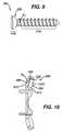
- FIG. 7is a side view of one embodiment of a bone screw according to the present invention.
- FIG. 8is a cut-away view of another embodiment of an aperture, split bushing, and bone screw according to the present invention.
- FIG. 9is a side view of another embodiment of a bone screw according to the present invention.
- FIG. 10is a cut-away, side view of a plate having apertures adapted to receive the bone screw shown in FIG. 9 .
- the present inventionprovides a spinal fixation plate having at least one aperture for receiving a bone screw.
- the plateis adapted to be attached to adjacent vertebrae to maintain the vertebrae in and fixed position and thereby provide biomechanical stability to the vertebra.
- the platecan be used in connection with a variety of spinal implants, including inner body fusion devices, fusion cages, bone grafts, artificial discs, or other vertebral implants, and it can optionally be adapted for use in both mating or non-mating relationships with the inner body fusion devices or other vertebral implant.
- FIGS. 1A-2Billustrate one embodiment of spinal fixation plate 10 .
- the plate 10has a substantially elongate shape and it includes a mid-portion 12 that is positioned between superior and inferior portions 14 , 16 .
- Each portion 12 , 14 , 16includes an anterior face 12 a , 14 a , 16 a and a posterior face 12 b , 14 b , 16 b , respectively, and the portions 12 , 14 , 16 together define a longitudinal axis L extending therealong.
- the mid-portion 12 of the plate 10also includes opposed lateral sides 12 c , 12 d extending therealong between the superior and inferior portions 14 , 16 .
- the superior and inferior portions 14 , 16are adapted to mate to superior and inferior vertebrae, respectively, and the mid-portion 12 extends therebetween to maintain the vertebrae at a fixed position with respect to one another.
- the plate 10preferably includes one or more apertures or thru-bores formed therein for receiving a fastening element, such as a bone screw, to attach the plate 10 to the adjacent vertebrae.
- each portion 14 , 16includes two thru-bores 20 a , 20 b , 22 a , 22 b formed therein.
- the thru-bores 20 a , 20 b , 22 a , 22 bare preferably formed on opposed sides of the longitudinal axis L of the plate 10 such that each of the superior and inferior portions 14 , 16 of the plate 10 include first and second opposed thru-bore tabs 15 a , 15 b , 17 a , 17 b .
- the thru-bores 20 a , 20 b , 22 a , 22 bcan have a variety of configurations, and exemplary configurations will be discussed in more detail with respect to FIGS. 6-10 .
- the superior and inferior portions 14 , 16 of the plate 10can also be adapted to position the thru-bores 20 a , 20 b , 22 a , 22 b at a particular location with respect to the adjacent vertebrae.
- the superior and inferior portions 14 , 16can be angled with respect to the mid-portion 12 and more particularly, as best shown in FIG. 2A , the superior and inferior portions 14 , 16 can extend in a direction that is anterior to the anterior face 12 a of the mid-portion 12 .
- the superior and inferior portions 14 , 16can be positioned on the anterior rim of each vertebra, which is a location that is between the anterior face and the endplate of each vertebra, e.g., along an edge of the vertebrae at the endplate/cortical junction. This location, which will be discussed in more detail with respect to FIG. 2C , is hereinafter referred to as the anterior rim of a vertebra.
- the angle aalso causes the mid-portion 12 to be substantially flush or sub-flush with respect to the anterior surface of each vertebra, thereby minimizing the anterior prominence of the plate 10 .
- the positionalso allows locking mechanisms, such as bone screws, to be inserted through the thru-bores 20 a , 20 b , 22 a , 22 b , through the anterior rims of the vertebrae, and into the vertebral bodies.
- locking mechanismssuch as bone screws
- the angulation of the superior and inferior portions 14 , 16can vary depending on the intended use, but in an exemplary embodiment the angle ⁇ T between the anterior surface 14 a , 16 a of the superior and inferior portions 14 , 16 and the anterior surface 12 a of the mid-portion 12 is less than about 15°, and more preferably the angle ⁇ T is about 10°. A person having ordinary skill in the art will appreciate that the angle ⁇ T can be greater than 15°.
- the plate 10can also or alternatively have a curve X, as best shown in FIGS. 1B , 1 C, and 2 B, that is formed about the longitudinal axis L in a sagittal plane, which extends in a superior-inferior direction and dissects the posterior and anterior faces 12 a , 12 b , 14 a , 14 b , 16 a , 16 c of the plate 10 .
- the curve Xis preferably only formed about the longitudinal axis L that extends between the superior and inferior portions 14 , 16 .
- the plate 10can be curved such that the opposed edges 12 c , 12 d of the mid-portion 12 are substantially longitudinally straight, but they are positioned posterior to the posterior face 12 b of the mid-portion 12 .
- the posterior face 12 b , 14 b , 16 b of each portion 12 , 14 , 16can have a substantially concave shape about the longitudinal axis L.
- the anterior face 12 a , 14 a , 16 a of each portion 12 , 14 , 16can also optionally have a substantially convex shape about the longitudinal axis L to correspond to the posterior face 12 b , 14 b , 16 b.
- the curve Xcan also continue through the superior and inferior portions 14 , 16 of the plate 10 , such that the opposed edges 14 c , 14 d , 16 c , 16 d of the superior and inferiors portions 14 , 16 are positioned posterior to the posterior faces 14 b , 16 b thereof.
- the superior and inferior portions 14 , 16can also be angled in a direction anterior to the anterior faces 14 a , 16 a thereof.
- the opposed thru-bore tabs 15 a , 15 b , 17 a , 17 bare not only angled anterior to the anterior face 12 a of the mid-portion 12 of the plate 10 , but they are also angled toward one another in a posterior direction.
- angle ⁇ xshown in FIGS. 1C and 2B
- the angle ⁇ x between the thru-bore tabs 15 a , 15 b , 17 a , 17 bis in the range of about 150° to 180°, and more preferably the angle is about 160°.
- the angle ⁇ xis 180°, the plate 10 will not have a curve X formed therein, but rather it will be substantially planar.
- the plate 10can be implanted in the lumbar, cervical, or thoracic regions of the patient's spine, and thus the size of the plate 10 will vary depending on the intended use.
- the plate 10can also be adapted for use in various surgical approaches, but preferably the plate 10 is adapted for anterior fixation.
- the plate 10has a length l and/or width w that is adapted for use in the lumbar region of a patient's spine. More preferably, the plate 10 has a length l that is less than a distance between the adjacent vertebrae to which the plate 10 is adapted to be mated to.
- the plate 10can be adapted for a variety of other uses and the configuration of the plate 10 can vary depending on the intended use. Moreover, a variety of plates 10 having various sizes and configurations can be provided as part of a kit, allowing a surgeon to select the appropriate plate 10 based on the intended use.
- FIG. 2Cillustrates plate 10 implanted in a patient's spinal column.
- the plate 10is shown mated to adjacent vertebrae 50 , 52 having an implant, e.g., fusion cage 30 , disposed therebetween.
- the adjacent vertebrae 52 , 54are distracted, at least a portion of the disc is removed, and the area is prepared using techniques known in the art.
- the fusion cage 30Prior to inserting the fusion cage 30 between the adjacent vertebrae 52 , 54 , the fusion cage 30 can be filled with autograft, allograft bone, and/or demineralized bone matrix to promote fusion.
- the fusion cage 30is then positioned between the vertebrae 52 , 54 using a variety of devices.
- Distractor and spreader devicesare known in the art, and are effective for separating adjacent vertebrae, and optionally assisting with insertion of the implant.
- Typical distractorsinclude two opposed blade members which are inserted between the adjacent vertebrae, and then opened to separate the vertebrae.
- the fusion cage 30can then be inserted into the disc space either manually, or using an impacting device, such as a mallet.
- the fixation plate 10can be placed adjacent to the anterior face 32 of the fusion cage 30 to position the superior and inferior portions 14 , 16 of the plate 10 against the anterior rims 52 a , 54 a of the adjacent vertebrae 52 , 54 .
- the plate 10is preferably not fixedly attached to the fusion cage 30 such that the two components are in a non-mating relationship with one another. In other words, the plate 10 and the fusion cage 30 remain as separate components from one another.
- One or more bone screwscan then be inserted through the thru-bores 20 a , 20 b , 22 a , 22 b in the superior and inferior portions 14 , 16 of the plate 10 to secure the plate 10 to the adjacent vertebrae 52 , 54 .
- a person skilled in the artwill appreciate that various procedures and tools can be used to position the plate 10 against the adjacent vertebrae and to prepare the vertebrae for receiving the bone screws.
- the plate 10can also optionally include various features to allow the plate 10 to be coupled to a tool for implanting the plate 10 .
- FIGS. 3A-3Billustrate another embodiment of a spinal fixation plate 120 .
- the plate 120is adapted to mate to a vertebral implant, such as a fusion cage 110 , shown in FIGS. 4A-4B .
- FIG. 4Aillustrates plate/cage assembly 100 .
- the plate 120can have a generally planar shape and it includes a mid-portion 126 that is positioned between superior and inferior portions 128 , 130 .
- the superior portion 128 of the plate 120is adapted to extend beyond a superior surface 102 of the fusion cage 110
- the inferior portion 130 of the plate 120is adapted to extend beyond an inferior surface 104 of the fusion cage 110 .
- the mid-portion 126 of the plate 120can be curved to contour the shape of an anterior face 108 of the fusion cage 110 .
- Each of the superior and inferior portions 128 , 130 of the plate 120further include at least one aperture 122 a - d formed therein for receiving a bone screw to secure the plate 120 to a vertebra.
- the superior and inferior portions 128 , 130 of the plate 120each include two apertures 122 a , 122 b , 122 c , 122 d formed therein.
- the apertures 122 a - dcan have a variety of configurations, and exemplary configurations will be discussed in more detail with respect to FIGS. 6-10 .
- FIGS. 4A-4Billustrate plate 120 mated to implant 110 , and apertures 122 a - d having bone screws 146 and 148 disposed therethrough, each having a head and a shank.
- the superior and inferior portions 128 , 130 of the plate 120can also extend at an angle with respect to the mid-portion 126 of the plate 120 .
- FIG. 4Awhich shows plate 120 mated to cage 110
- superior and inferior portions 128 , 130are angled with respect to the remainder of the plate 120 so that screws 146 and 148 extending therethrough are angled with respect to a medial plane “P” of the body 110 .
- the angle formed by the tab(s) and plate, as well as by the screw(s) and medial plane,is designated as “ ⁇ ” and it can vary depending on a patient's particular anatomy. Although the angle a can range from 15° to 60°, for most applications the angle ⁇ is about 20°.
- the superior and inferior portions 128 , 130can be flexible or readily bent with respect to the remainder of the plate 120 .
- the mid-portion 126 of the plate 120can also include a central aperture 132 formed therein.
- the central aperture 132is positioned such that it is aligned with a central bore (not shown) formed in the fusion cage 110 when the plate 120 is mated to the cage 110 .
- the central aperture 132 and borecan be effective to receive an insertion tool and/or a fastening element, such as a screw, effective to mate the plate 120 to the fusion cage 110 .
- the fastening elementcan be fixedly, but rotatably disposed within the central aperture 132 of the plate 120 , and/or it can be adapted to snap into the central bore in the fusion cage 110 .
- the fastening elementcan further be adapted to engage the fusion cage 110 upon rotation thereof.
- a person having ordinary skill in the artwill appreciate that a variety of techniques can be used to mate the plate 120 to the fusion cage 110 .
- the plate 120can also include a mating element 124 a, 124 b that is adapted to slidably engage and mate the plate 120 to the anterior face 108 of the fusion cage 110 in an anterior-posterior direction. While the mating element 124 a , 124 b can have a variety of configurations, FIGS. 3A-3B illustrate first and second opposed arms 124 a, 124 b that extend outward from the plate 120 in a direction substantially perpendicular to the substantially planar surface of the plate 120 .
- the arms 124 a , 124 bcan be positioned anywhere on the plate 120 , but preferably the first arm 124 a is positioned just superior to the mid-portion 126 of the plate 120 between the central aperture 132 and the superior apertures 122 a , 122 b formed in the superior portion 128 of the plate 120 , and the second arm 124 b is positioned just distal to the mid-portion 126 of the plate 120 between the central aperture 132 and the inferior apertures 122 c , 122 d formed in the inferior portion 130 of the plate 120 .
- the arms 124 a , 124 bare positioned such that, when the plate 120 is mated to the fusion cage 110 , the arms 124 a , 124 b are configured to engage the superior and inferior faces 102 , 104 of the fusion cage 110 .
- each arm 124 a , 124 bcan also vary, but preferably each arm 124 a , 124 b is adapted to contour the shape of the fusion cage 110 .
- the arms 124 a , 124 bare preferably convex to contour the shape of the fusion cage 110 .
- each arm 124 a , 124 bcan vary as well, but preferably each arm 124 a , 124 b has a length l a sufficient to enable the arms 124 a , 124 b to extend across at least a portion of the superior and inferior surfaces 102 , 104 of the fusion cage 110 , and a width w a sufficient to allow the arms 124 a , 124 b to grasp the fusion cage 110 .
- Each arm 124 a , 124 bcan have a variety of configurations, but preferably the arms 124 a , 124 b include an engagement element 136 a , 136 b effective to engage the superior and inferior faces 102 , 104 of the fusion cage 110 .
- the engagement element 136 a , 136 bpreferably provides an interference fit to temporarily secure the plate 120 to the fusion cage 110 .
- the engagement element 136 a , 136 bcan have a variety of configurations, the engagement element 136 a , 136 b can be, for example, in the form of at least one protrusion formed on an inner surface of each arm 124 a , 124 b that is adapted to sit in at least one indentation 138 (shown in FIG. 4B ) formed in each of the superior and inferior faces 102 , 104 of the fusion cage 110 .
- the protrusion 136 a , 136 b on each arm 124 a , 124 bhas a generally elongate shape. The indentation will be discussed in more detail with respect to FIG. 4B below.
- the arms 124 a , 124 bcan optionally be flexible to allow the arms 124 a , 124 b to flex outward while sliding the plate 120 onto the fusion cage 110 , and to allow the arms 124 a , 124 b to then return to their original state whereby the protrusions 136 a , 136 b on the arms 124 a , 124 b to snap into the indentations 138 (only one indentation is shown in FIG. 4B ) formed in the superior and inferior faces 102 , 104 of the fusion cage 110 .
- the fusion cage 110can have a variety of configurations, but as previously stated it generally includes superior 102 , inferior 104 , posterior 106 , and anterior 108 faces.
- the inferior and superior faces 102 , 104can have a flat to slightly convex shape, and/or a slightly tapered (about 10 °) or wedge profile, wherein the body 110 is thicker at the anterior face 108 than at the posterior face 106 .
- a central bore(not shown) can be formed in the anterior face 102 of the fusion cage 110 , and it preferably includes threads formed therein for receiving a fastening element, e.g., a screw.
- the threadsare preferably spinal lock threads to provide a secure connection between the plate and the cage.
- First and second transverse elements 140 , 142can join the posterior face 106 to the anterior face 108 , and a guide path 144 for receiving an insertion tool can extend across the superior and inferior faces 102 , 104 between the posterior and anterior faces 106 , 108 .
- Fusion cage 110further includes an arm-seating recess formed in each of the superior and inferior surfaces 102 , 104 for receiving the arms 124 a , 124 b formed on the plate 120 .
- the recessescan be formed in the guide path 144 , or more preferably the guide path 144 can form arm-seating recesses, as is shown in FIG. 4B .
- Each guide path 144(only the guide path on the superior surface 102 is shown), or arm-seating recess, preferably has a depth d sufficient to receive the corresponding arm 124 a , 124 b formed on the plate 120 such that, when the plate 120 is mated to the fusion cage 110 , the arms 124 a , 124 b are flush with the superior and inferior surfaces 102 , 104 of the fusion cage 110 .
- Thisis particularly advantageous in that it allows the fusion cage 110 to be positioned between adjacent vertebrae prior to inserting the arms 124 a , 124 b into the arm-seating recesses 144 to attach the plate 120 to the fusion cage 110 .
- Each of the arm-seating recesses 144further preferably includes at least one indentation 138 formed therein for receiving the protrusion 136 a , 136 b formed on the inner surface of each arm 124 a , 124 b .
- the indentation 138is in the form of an elongate groove that is adapted to receive and seat the protrusion 136 a , 136 b formed on each arm 124 a , 124 b .
- the arms 124 a , 124 bcan merely slid into and seat within the recess 144 formed in the fusion cage 110 , and that they do not need to engage the fusion cage 110 .
- An engagement mechanismis merely preferred to allow the plate 120 to be at least temporarily secured to the fusion cage 110 during implantation.
- the fusion cage 110can optionally include a number of bone engaging surface features 146 formed on the superior and inferior surfaces 102 , 104 to facilitate the secure mounting of the cage 110 between adjacent vertebrae.
- the bone engaging surface features 146can be present on the entire surface area of the superior and inferior surfaces 102 , 104 , or optionally, selected regions of the superior and inferior surfaces 102 , 104 can be free of surfaces features 146 .
- the bone engaging surface features 146can have a variety of shapes, but are preferably in the form of wedge-shaped ridges that extend is a direction transverse to the posterior 106 and anterior 108 faces of the fusion cage 110 .
- Each bone engaging surface feature 146includes a posterior side wall 148 and an anterior side wall 149 , which meet at a peak 150 .
- each surface feature 146can be angled or sloped to facilitate insertion of the cage 110 between adjacent vertebrae and to assist in preventing the fusion cage 110 from becoming dislodged.
- the size of the surface features 146can also vary but preferably the surface features 146 have a size sufficient to cause each surface feature 146 to engage and penetrate the adjacent vertebrae. It will be understood that while ridges 146 have been shown in a preferred embodiment, it is contemplated that there are a variety of structures which could provide a surface for effective engagement with the vertebral bodies to limit expulsion from the disc space.
- FIG. 5illustrates another embodiment of a spinal fixation assembly 100 ′.
- the arms 124 a , 124 b on the plate 120are adapted to extend into opposed superior and inferior bores 152 , 154 , rather than recesses 144 , formed in the fusion cage 110 ′.
- the arms 124 a , 124 bcan merely slide into the bores 152 , 154 that extend into the fusion cage 110 ′ to provide an alignment mechanism between the cage 110 ′ and the plate 120 .
- the bores 152 , 154can optionally be adapted to receive the engagement mechanism 136 a , 136 b formed on each arm 124 a , 124 b to at least temporarily secure the arms 124 a , 124 b within the bores 152 , 154 .
- the arms 124 a , 124 b and the bores 152 , 154can each be tapered to provide an interference fit between the arms 124 a , 124 b and the bores 152 , 154 .
- the arms 124 a , 124 bcan include a press-fit pin that depresses upon insertion of the arms 124 a , 124 b into the bores 152 , 154 , and then once each arm 124 a , 124 b is fully inserted into the bore 152 , 154 , returns to its originally state whereby the pins extending into corresponding indentations formed within the bores 152 , 154 .
- a person having ordinary skill in the artwill appreciate that a variety of mechanisms can be used to secure the arms 124 a , 124 b of the plate 120 within the bores 152 , 154 formed in the fusion cage 110 ′.
- the adjacent vertebraeare prepared and distracted and the fusion cage 110 is placed therebetween, as previously described above.
- the fixation plate 120can be placed adjacent to the anterior face 108 of the fusion cage 110 to position the superior and inferior portions 128 , 130 of the plate 110 against the anterior rims of the adjacent vertebrae.
- the plate 120is then preferably mated to the anterior face 108 of the fusion cage 110 by positioning the arms 124 a , 124 b between the superior and inferior surfaces 102 , 104 of the fusion cage 110 and the adjacent vertebrae.
- the arms 124 a ′, 124 b ′ of the plate 120 ′can be easily slid into the recesses 152 , 154 to engage the cage 110 ′.
- a center screw(not shown) can then be inserted through a central aperture 132 in the plate 120 and through a bore in the cage (e.g., FIG. 5 shows bore 134 formed in the cage 110 ′) to secure the plate 120 to the cage 110 , and one or more bone screws (only two bone screws 146 , 148 are shown in FIG. 4A ) can be inserted through the apertures 122 a , 122 b , 122 c , 122 d in the superior and inferior portions 128 , 130 of the plate 120 to secure the plate 120 to the adjacent vertebrae.
- FIGS. 6-10illustrate embodiments of different apertures for use with a plate according to the present invention.
- the aperturesare adapted to provide a more secure connection between the plate and a vertebrae. While the various embodiments will be described in relation to particular spinal fixation plates disclosed herein, a person having ordinary skill in the art will appreciate that the virtually any technique known in the art can be used with any of the various embodiments of spinal fixation plates, as well as with a variety of vertebral implants.
- FIG. 6illustrates one embodiment of an aperture 160 formed in a tab 166 of a plate and having a split bushing 162 disposed therein.
- a bone screw 174is disposed through the aperture 160 and the split bushing 162 .
- the aperture 160includes a first end 168 , a second end 170 , and a sidewall 172 extending therebetween.
- the first end 168is preferably adapted to receive a bone screw 174 , or similar type of fixation element, and to seat the head 164 of the bone screw 174 therein.
- the aperture 160can extend through the tab 166 in the plate along a central axis a a that is substantially perpendicular to a central plane a p of the tab 166 , or alternatively the central axis a a of the aperture 160 can be offset from, or disposed at an angle with respect to, the plane a p of the tab 166 .
- the sidewall 172 of the aperture 160can also vary and can be either substantially planar along the length thereof between the first and second ends 168 , 170 of the aperture 160 , or the sidewall 172 can be curved or can extend at an angle. As shown in FIG. 6 , the sidewall 172 has a substantially concave shape to receive the split bushing 162 .
- the split bushing 162is disposed within the aperture 160 and it has a generally cylindrical shape with a gap (not shown) formed therein to allow the bushing 162 to be expanded.
- the split bushing 162includes an outer surface 176 which can have a shape adapted to conform to the shape of the sidewall 172 of the aperture 160 , and an inner surface 178 which is adapted to receive a bone screw 174 .
- the split bushing 160can have a convex outer surface 172 to allow the split bushing 162 to sit within the concave sidewall 172 of the aperture 160 .
- the split bushing 162further includes an inner diameter d b that can vary between opposed first and second ends 168 , 170 of the split bushing 162 .
- the diameter d b of the bushing 162 at the first end 168is larger than the diameter d b of the bushing 162 at the second end 170 .
- the tapered diameterallows the bushing 162 to receive a portion of the tapered undersurface of the head 164 of the bone screw 174 .
- FIG. 7illustrates the bone screw 174 in more detail having a tapered head 164 adapted to fit within the split bushing 162 shown in FIG. 6 .
- the bone screw 174includes a head 164 and a threaded shank 180 .
- the head 164is tapered preferably at an angle substantially the same as the angle of the tapered inner diameter d b of the split bushing 162 .
- the split bushing 162expands and provides an interference fit between the bone screw 174 and the aperture 160 , thereby creating a rigid lock to secure the plate to a vertebrae.
- the tapered diameter d b of the bushing 162also allows the bone screw 174 to be inserted at variable angles a s with respect to the central axis a a of the aperture, as shown in FIG. 6 .
- FIG. 8illustrates another embodiment of an aperture 190 having a split bushing 192 disposed therein.
- the split bushing 192includes threads 194 formed on an inner surface thereof to mate with corresponding threads 196 formed on a bone screw 198 .
- the threads 194 , 196are particularly effective to prevent the bone screw 198 from backing out of the aperture 190 , and to provide a rigid lock between the screw 198 and the aperture 190 thereby securely mating the plate to a vertebrae.
- the aperture 190preferably includes an anti-rotation mechanism effective to prevent the split bushing 192 from rotating while the screw 198 is threaded therethrough.
- the anti-rotation mechanismcan have a variety of configurations and, by way of non-limiting example, can be a pin or raised protrusion (not shown) disposed within the aperture 190 and adapted to extend into the gap formed in the split bushing 192 .
- FIGS. 9-10illustrate yet another embodiment of an aperture 200 and bone screw 202 for use with the present invention.
- the aperture 200includes a first end 204 , a second end 206 , and a sidewall 208 extending therebetween and defining an inner lumen 210 .
- the inner lumen 210includes a first portion 214 positioned adjacent the first end 204 , and a second portion 212 positioned adjacent the second end 206 of the aperture 200 .
- the first portion 214 of the inner lumen 210has a shape and size adapted to receive the head 216 of a bone screw 202 .
- FIG. 9illustrates an exemplary embodiment of a bone screw 202 for use with a plate having an aperture 200 as shown in FIG. 10 .
- the bone screw 202includes a head 216 and a threaded shank 218 .
- the head 216 of the bone screw 202includes a substantially convex, slightly rounded outer surface 220 .
- the first portion 214 of the inner lumen 210 of the aperture 200has a concave sidewall 222 , e.g., a generally spherical recess, to allow the rounded head 216 of the bone screw 202 to seat therein.
- the second portion 212 of the inner lumen 210is substantially cylindrical and has a shape and size adapted to receive the threaded shank 218 of a bone screw 202 .
- the second portion 212 of the inner lumen 210has a diameter d 2 greater than a diameter d 1 of the shank 218 of the bone screw 202 .
- the first and second portions 214 , 212 of the inner lumen 210allow the bone screw 202 to translate within the aperture 200 such that the screw 202 can be inserted at varying angles.
- the aperture 200does not include a split bushing to provide a rigid connection between the bone screw 202 and the plate, the aperture 200 allows the full exertion of natural biomechanical compression stresses through the vertebral bodies into which the screw 202 is inserted.
- the bone screw 174can include a shoulder 230 formed thereon that abuts a corresponding shoulder (not shown) formed in an aperture.
- the shoulder 230is formed by a difference, or stepped increase, in the diameter d 3 , d 4 of the screw head 164 and in the diameter of the aperture, or in the split bushing if the aperture includes one.
- the bone screw 174is inserted through an aperture and once the shoulder 230 on the screw head 164 passes the shoulder 230 in the aperture, or in the split bushing, the shoulders will engage thereby preventing the screw 174 from backing out of the aperture.
- the fusion cage and plate of the present inventioncan be made from a variety of materials.
- a carbon fiber composite or other radiolucent materialis well suited for fabrication of the body, and titanium or carbon fiber composites are suitable materials for the plate 20 .
- the fusion cagecan be sufficiently broad and thick so that only a single cage is needed to replace an excised disc.
- the profile and slightly bowed or convex superior and inferior surfaces of the fusion cage bodyclosely approximate the shape of a natural disc and provide an excellent, stable, load-bearing surface.
- the platewhen included, ensures that the body will not become dislodged from the spine, yet is readily accessible with an anterior approach. Further, the plate allows bone screws to be deeply embedded into the vertebral bodies without piercing or otherwise damaging the hard, load-bearing, cortical bone. Also, both the plate and the body include features that allow for relatively easy manipulation and insertion with appropriately configured surgical tools.
Landscapes
- Health & Medical Sciences (AREA)
- Orthopedic Medicine & Surgery (AREA)
- Life Sciences & Earth Sciences (AREA)
- Neurology (AREA)
- Engineering & Computer Science (AREA)
- Biomedical Technology (AREA)
- Surgery (AREA)
- General Health & Medical Sciences (AREA)
- Veterinary Medicine (AREA)
- Heart & Thoracic Surgery (AREA)
- Public Health (AREA)
- Animal Behavior & Ethology (AREA)
- Molecular Biology (AREA)
- Medical Informatics (AREA)
- Nuclear Medicine, Radiotherapy & Molecular Imaging (AREA)
- Cardiology (AREA)
- Oral & Maxillofacial Surgery (AREA)
- Transplantation (AREA)
- Vascular Medicine (AREA)
- Prostheses (AREA)
- Surgical Instruments (AREA)
Abstract
Description
This application is a continuation of U.S. patent application Ser. No. 12/883,832, filed on Sep. 16, 2010 entitled “Spinal Fixation Plates,” which is a divisional of U.S. patent application Ser. No. 10/927,778 (now U.S. Pat. No. 7,819,903), filed on Aug. 27, 2004 and entitled “Spinal Fixation Plates,” which is a continuation-in-part of U.S. patent application Ser. No. 10/403,930 (now U.S. Pat. No. 7,112,222), filed on Mar. 31, 2003 and entitled “Anterior Lumbar Interbody Fusion Cage With Locking Plate.” These references are hereby expressly incorporated herein by reference.
The present invention relates to medical devices, and more particularly to spinal fixation plates for promoting fusion of adjacent vertebral bodies.
Advancing age, as well as injury, can lead to changes in the bones, disks, joints, and ligaments of the spine producing pain from nerve root compression. Under certain circumstances, alleviation of pain can be provided by performing a spinal fusion. This is a procedure that involves joining two or more adjacent vertebrae with a bone fixation device so that they no longer are able to move relative to each other. For a number of known reasons, bone fixation devices are useful for promoting proper healing of injured or damaged vertebral bone segments caused by trauma, tumor growth, or degenerative disc disease. The external fixation devices immobilize the injured bone segments to ensure the proper growth of new osseous tissue between the damaged segments. These types of external bone fixation devices often include internal bracing and instrumentation to stabilize the spinal column to facilitate the efficient healing of the damaged area without deformity or instability, while minimizing any immobilization and post-operative care of the patient.
One such device is a bone fixation plate that is used to immobilize adjacent skeletal parts such as bones. Typically, the fixation plate is a rigid metal or polymeric plate positioned to span bones or bone segments that require immobilization with respect to one another. The plate is fastened to the respective bones, usually with bone screws, so that the plate remains in contact with the bones and fixes them in a desired position. Bone plates can be useful in providing the mechanical support necessary to keep vertebral bodies in proper position and bridge a weakened or diseased area such as when a disc, vertebral body or fragment has been removed.
Such plates have been used to immobilize a variety of bones, including vertebral bodies of the spine. These bone plate systems usually include a rigid bone plate having a plurality of screw openings. The openings are either holes or slots to allow for freedom of screw movement. The bone plate is placed against the damaged vertebral bodies and bone screws are used to secure the bone plate to the spine and optionally to a prosthetic implant positioned between the adjacent vertebrae.
While several types of bone fixation plates exists, there remains a need for improved spinal fixation plates.
The present invention generally provides spinal fixation plates, spinal implants for use with spinal fixation plates, and methods for implanting the same. In one embodiment of the present invention, a spinal fixation plate is provided for maintaining adjacent vertebrae in a fixed position with respect to one another. The fixation plate includes a mid-portion with opposed superior and inferior portions. The superior and inferior portions can each include at least one thru-bore formed therein for receiving a fastening element, and the superior and inferior portions are preferably positioned at an angle with respect to the mid-portion such that, when the plate is positioned in relation to adjacent superior and inferior vertebrae, the superior and inferior portions of the plate are positioned adjacent to the anterior rim of each vertebra. In an exemplary embodiment, the superior and inferior portions are angled in a direction anterior to the anterior face of the mid-portion, and the angle is preferably less than about 15°.
In one exemplary embodiment, the plate can include a posterior curvature formed about a longitudinal axis. As a result, the plate can have a substantially concave posterior face, and the plate can also optionally have a substantially convex anterior face. In another embodiment, the superior and inferior portions of the plate preferably each include first and second thru-bore tabs formed on opposed sides of the longitudinal axis of the plate. When combined with the curvature in the plate, the first and second opposed tabs can be angled toward one another in a posterior direction. In an exemplary embodiment, the angle between a posterior face of the first thru-bore tab and a posterior face of the second thru-bore tab in each of the superior and inferior portions is in the range of about 150° to 180°, and more preferably the angle is about 160°.
In yet another embodiment of the present invention, a spinal fixation plate is provided having a mid-portion and opposed superior and inferior portions extending at an angle with respect to the mid-portion in a direction anterior to an anterior face of the mid-portion. The superior and inferior portions each preferably include first and second thru-bore tabs formed on opposed sides of a longitudinal axis of the plate. The first and second thru-bores tabs are preferably angled toward one another in a posterior direction. The first and second thru-bores tabs in the superior and inferior portions also preferably each include a thru-bore formed therein and adapted to receive a fastening element to mate the plate to adjacent vertebrae. The mid-portion can also optionally be curved about a longitudinal axis, preferably in a posterior direction, such that opposed side edges of the mid-portion are positioned posterior to a posterior face of the mid-portion at the longitudinal axis of the mid-portion. At least a portion of the plate can have a substantially concave posterior face as a result of the curve formed therein. At least a portion of the plate can also optionally have a substantially convex anterior face as a result of the curve formed therein.
The present invention also provides a spinal fixation kit that includes at least one fixation plate and an implant that is adapted to be disposed between adjacent vertebra and that has posterior, anterior, superior, and inferior faces. The fixation plate preferably has a mid-portion with opposed superior and inferior portions that define a plate length that is preferably greater than a height of the implant between the superior and inferior faces. The superior and inferior portions also preferably include first and second opposed thru-bore tabs that extend in a direction anterior to an anterior face of the mid-portion of the fixation plate, and/or that extend at an angle toward one another in a posterior direction. The kit can also include at least one fastening element that is adapted to extend through a thru-bore tab in the superior and inferior portions of the fixation plate to mate the plate to adjacent vertebrae.
The present invention also provides methods for implanting a spinal fixation plate. In one exemplary embodiment, the method can include one or more of the following steps: distracting adjacent vertebrae, removing at least a portion of the disc disposed between the adjacent vertebrae, positioning a spinal implant between the adjacent vertebrae, and positioning a spinal fixation plate adjacent to an anterior face of the spinal implant such the opposed superior and inferior portions of the spinal fixation plate are positioned on the anterior rim of each vertebra. A fastening element can then be inserted through one or more of the thru-bore formed in the spinal fixation plate to attach the spinal fixation plate to the adjacent vertebrae. In an exemplary embodiment, the superior and inferior portions of the spinal fixation plate include longitudinally opposed thru-bores tabs, each having a thru-bore formed therein for receiving a fastening element. The opposed thru-bore tabs in the superior portion are preferably angled toward one another in a posterior direction, and the thru-bore tabs in the inferior portion are also preferably angled toward one another in a posterior direction. The superior and inferior portions of the plate can also be angled in a direction anterior to an anterior face of a mid-portion of the plate, such that the mid-portion of the plate is flush or sub-flush relative to an anterior face of the adjacent vertebrae.
In yet another embodiment of the present invention, a spinal fixation assembly is provided including a fusion cage with posterior, anterior, superior, and inferior faces, and a plate having at least one aperture for receiving a bone screw and being configuration to slidably mate to the fusion cage. In one embodiment, the plate includes a mating element for engaging the cage in an anterior-posterior direction. The mating element can have a variety of configurations, but it preferably takes the form of opposed first and second arms that are adapted to engage the superior and inferior faces of the fusion cage. The first and second arms can be flexible, and preferably extend from the plate and are adapted to seat on the superior and inferior faces of the fusion cage. The superior and inferior faces of the fusion cage can each include an arm-seating recess formed therein for receiving the first and second arms on the plate. These recesses allow the arms to sit flush with the superior and inferior faces when disposed within the arm-seating recesses. In an exemplary embodiment, the first and second arms are adapted to mate with the arm-receiving recesses formed on the fusion cage with an interference fit to temporarily secure the plate to the fusion cage.
In another embodiment, the anterior face of the fusion cage can include at least one bore formed therein, and the mating element can be at least one arm that is adapted to extend into the bore in the fusion cage to mate the plate to the fusion cage. In a preferred embodiment, the anterior face of the fusion cage includes a superior bore and an inferior bore formed therein, and the mating element comprises opposed first and second arms that are adapted to extend into the superior and inferior bores in the fusion cage to mate the plate to the fusion cage.
In another embodiment, the fusion cage includes an intermediate plane that separates the inferior face from the superior face to define an inferior side and a superior side, and the plate includes at least one inferior aperture on the inferior side of the fusion cage and at least one superior aperture on the superior side of the fusion cage. Each aperture in the plate can have a first end having an opening, a second, opposed end, and a sidewall extending therebetween that defines an inner lumen. The first end of each aperture preferably is a generally spherical recess formed in the plate for rotatably seating a head of a bone screw. A split bushing is preferably disposed within each aperture in the plate. Each aperture can optionally include an anti-rotation mechanism effective to prevent each split bushing from rotating within the aperture. The apertures and the split bushings can have a variety of configurations. In one embodiment, the sidewall of each aperture can be concave and each split bushing can include a convex outer surface. Each split bushing can also optionally include a shoulder formed therein that abuts a corresponding shoulder formed within each aperture. In another embodiment, each split bushing can include an inner surface having threads formed thereon that are adapted to mate with corresponding threads formed on a bone screw.
In other aspects, the inferior and superior apertures are disposed in inferior and superior portions. The portions, or tabs, are preferably angled with respect to the fusion cage in a direction anterior to the anterior face of the fusion cage. In an exemplary embodiment, each portion extends in a plane, and each aperture defines a central axis that extends through the aperture at an angle with respect to the plane of the portion in which the aperture is disposed.
The invention will be more fully understood from the following detailed description taken in conjunction with the accompanying drawings, in which:
In general, the present invention provides a spinal fixation plate having at least one aperture for receiving a bone screw. The plate is adapted to be attached to adjacent vertebrae to maintain the vertebrae in and fixed position and thereby provide biomechanical stability to the vertebra. The plate can be used in connection with a variety of spinal implants, including inner body fusion devices, fusion cages, bone grafts, artificial discs, or other vertebral implants, and it can optionally be adapted for use in both mating or non-mating relationships with the inner body fusion devices or other vertebral implant.
As indicated above, the superior andinferior portions plate 10 preferably includes one or more apertures or thru-bores formed therein for receiving a fastening element, such as a bone screw, to attach theplate 10 to the adjacent vertebrae. In the illustrated exemplary embodiment, eachportion bores bores plate 10 such that each of the superior andinferior portions plate 10 include first and second opposed thru-bore tabs bores FIGS. 6-10 .
The superior andinferior portions plate 10 can also be adapted to position the thru-bores inferior portions FIG. 2A , the superior andinferior portions anterior face 12aof the mid-portion12. As a result, when theplate 10 is implanted, the superior andinferior portions FIG. 2C , is hereinafter referred to as the anterior rim of a vertebra. When the superior andinferior portions plate 10. The position also allows locking mechanisms, such as bone screws, to be inserted through the thru-bores plate 10 also reduces the need for excessive vessel retraction.
The angulation of the superior andinferior portions anterior surface inferior portions anterior surface 12aof the mid-portion12 is less than about 15°, and more preferably the angle αTis about 10°. A person having ordinary skill in the art will appreciate that the angle αTcan be greater than 15°.
Theplate 10 can also or alternatively have a curve X, as best shown inFIGS. 1B ,1C, and2B, that is formed about the longitudinal axis L in a sagittal plane, which extends in a superior-inferior direction and dissects the posterior and anterior faces12a,12b,14a,14b,16a,16cof theplate 10. The curve X is preferably only formed about the longitudinal axis L that extends between the superior andinferior portions plate 10 can be curved such that theopposed edges posterior face 12bof the mid-portion12. As a result of the curve X, theposterior face portion anterior face portion posterior face
The curve X can also continue through the superior andinferior portions plate 10, such that the opposed edges14c,14d,16c,16dof the superior andinferiors portions inferior portions bore tabs anterior face 12aof the mid-portion12 of theplate 10, but they are also angled toward one another in a posterior direction. While the angle αx, shown inFIGS. 1C and 2B , can vary, in an exemplary embodiment the angle αxbetween the thru-bore tabs plate 10 will not have a curve X formed therein, but rather it will be substantially planar.
In use, theplate 10 can be implanted in the lumbar, cervical, or thoracic regions of the patient's spine, and thus the size of theplate 10 will vary depending on the intended use. Theplate 10 can also be adapted for use in various surgical approaches, but preferably theplate 10 is adapted for anterior fixation. In an exemplary embodiment, theplate 10 has a length l and/or width w that is adapted for use in the lumbar region of a patient's spine. More preferably, theplate 10 has a length l that is less than a distance between the adjacent vertebrae to which theplate 10 is adapted to be mated to. This allows the superior andinferior portions plate 10, and in particular the thru-bore tabs plate 10 can be adapted for a variety of other uses and the configuration of theplate 10 can vary depending on the intended use. Moreover, a variety ofplates 10 having various sizes and configurations can be provided as part of a kit, allowing a surgeon to select theappropriate plate 10 based on the intended use.
By way of non-limiting example,FIG. 2C illustratesplate 10 implanted in a patient's spinal column. In particular, theplate 10 is shown mated toadjacent vertebrae 50,52 having an implant, e.g.,fusion cage 30, disposed therebetween. Theadjacent vertebrae fusion cage 30 between theadjacent vertebrae fusion cage 30 can be filled with autograft, allograft bone, and/or demineralized bone matrix to promote fusion. Thefusion cage 30 is then positioned between thevertebrae fusion cage 30 can then be inserted into the disc space either manually, or using an impacting device, such as a mallet.
Once the fusion cage is in position, thefixation plate 10, and in particular theposterior surface 12bof theplate 10, can be placed adjacent to theanterior face 32 of thefusion cage 30 to position the superior andinferior portions plate 10 against theanterior rims adjacent vertebrae plate 10 is preferably not fixedly attached to thefusion cage 30 such that the two components are in a non-mating relationship with one another. In other words, theplate 10 and thefusion cage 30 remain as separate components from one another. One or more bone screws (only twoscrews 62a,64 are shown) can then be inserted through the thru-bores inferior portions plate 10 to secure theplate 10 to theadjacent vertebrae plate 10 against the adjacent vertebrae and to prepare the vertebrae for receiving the bone screws. Theplate 10 can also optionally include various features to allow theplate 10 to be coupled to a tool for implanting theplate 10.
Each of the superior andinferior portions plate 120 further include at least one aperture122a-dformed therein for receiving a bone screw to secure theplate 120 to a vertebra. As shown, the superior andinferior portions plate 120 each include twoapertures FIGS. 6-10 .FIGS. 4A-4B illustrateplate 120 mated to implant110, and apertures122a-dhavingbone screws
The superior andinferior portions plate 120 can also extend at an angle with respect to themid-portion 126 of theplate 120. In particular, referring toFIG. 4A , which showsplate 120 mated tocage 110, superior andinferior portions plate 120 so thatscrews body 110. The angle formed by the tab(s) and plate, as well as by the screw(s) and medial plane, is designated as “α” and it can vary depending on a patient's particular anatomy. Although the angle a can range from 15° to 60°, for most applications the angle α is about 20°. However, in other embodiments, the superior andinferior portions plate 120.
The mid-portion126 of theplate 120 can also include acentral aperture 132 formed therein. Thecentral aperture 132 is positioned such that it is aligned with a central bore (not shown) formed in thefusion cage 110 when theplate 120 is mated to thecage 110. Thecentral aperture 132 and bore can be effective to receive an insertion tool and/or a fastening element, such as a screw, effective to mate theplate 120 to thefusion cage 110. In one embodiment (not shown), the fastening element can be fixedly, but rotatably disposed within thecentral aperture 132 of theplate 120, and/or it can be adapted to snap into the central bore in thefusion cage 110. The fastening element can further be adapted to engage thefusion cage 110 upon rotation thereof. A person having ordinary skill in the art will appreciate that a variety of techniques can be used to mate theplate 120 to thefusion cage 110.
Still referring toFIGS. 3A-4B , theplate 120 can also include amating element plate 120 to theanterior face 108 of thefusion cage 110 in an anterior-posterior direction. While themating element FIGS. 3A-3B illustrate first and secondopposed arms plate 120 in a direction substantially perpendicular to the substantially planar surface of theplate 120. Thearms plate 120, but preferably thefirst arm 124ais positioned just superior to themid-portion 126 of theplate 120 between thecentral aperture 132 and thesuperior apertures superior portion 128 of theplate 120, and thesecond arm 124bis positioned just distal to themid-portion 126 of theplate 120 between thecentral aperture 132 and theinferior apertures inferior portion 130 of theplate 120. In other words, thearms plate 120 is mated to thefusion cage 110, thearms inferior faces fusion cage 110.
The shape of thearms arm fusion cage 110. By way of non-limiting example, where thefusion cage 110 has domed or convex superior andinferior surfaces arms fusion cage 110. The size of eacharm arm arms inferior surfaces fusion cage 110, and a width wasufficient to allow thearms fusion cage 110.
Eacharm arms engagement element inferior faces fusion cage 110. Theengagement element plate 120 to thefusion cage 110. While theengagement element engagement element arm FIG. 4B ) formed in each of the superior andinferior faces fusion cage 110. As shown inFIG. 3A , theprotrusion arm FIG. 4B below. Thearms arms plate 120 onto thefusion cage 110, and to allow thearms protrusions arms FIG. 4B ) formed in the superior andinferior faces fusion cage 110.
Referring now toFIG. 4B ,fusion cage 110 is shown in more detail. Thefusion cage 110 can have a variety of configurations, but as previously stated it generally includes superior102, inferior104,posterior 106, and anterior108 faces. The inferior andsuperior faces body 110 is thicker at theanterior face 108 than at theposterior face 106.
A central bore (not shown) can be formed in theanterior face 102 of thefusion cage 110, and it preferably includes threads formed therein for receiving a fastening element, e.g., a screw. The threads are preferably spinal lock threads to provide a secure connection between the plate and the cage. First and secondtransverse elements posterior face 106 to theanterior face 108, and aguide path 144 for receiving an insertion tool can extend across the superior andinferior faces anterior faces
Thefusion cage 110 can optionally include a number of bone engaging surface features146 formed on the superior andinferior surfaces cage 110 between adjacent vertebrae. The bone engaging surface features146 can be present on the entire surface area of the superior andinferior surfaces inferior surfaces posterior 106 and anterior108 faces of thefusion cage 110. Each bone engagingsurface feature 146 includes aposterior side wall 148 and an anterior side wall149, which meet at apeak 150. Theside walls 148,149 of eachsurface feature 146 can be angled or sloped to facilitate insertion of thecage 110 between adjacent vertebrae and to assist in preventing thefusion cage 110 from becoming dislodged. The size of the surface features146 can also vary but preferably the surface features146 have a size sufficient to cause eachsurface feature 146 to engage and penetrate the adjacent vertebrae. It will be understood that whileridges 146 have been shown in a preferred embodiment, it is contemplated that there are a variety of structures which could provide a surface for effective engagement with the vertebral bodies to limit expulsion from the disc space.
In use, the adjacent vertebrae are prepared and distracted and thefusion cage 110 is placed therebetween, as previously described above. Once thefusion cage 110 is in position, thefixation plate 120 can be placed adjacent to theanterior face 108 of thefusion cage 110 to position the superior andinferior portions plate 110 against the anterior rims of the adjacent vertebrae. Theplate 120 is then preferably mated to theanterior face 108 of thefusion cage 110 by positioning thearms inferior surfaces fusion cage 110 and the adjacent vertebrae. Whereplate 120′ is used and thecage 110′ includes arm-receivingrecesses 152,154, thearms 124a′,124b′ of theplate 120′ can be easily slid into therecesses 152,154 to engage thecage 110′. A center screw (not shown) can then be inserted through acentral aperture 132 in theplate 120 and through a bore in the cage (e.g.,FIG. 5 shows bore134 formed in thecage 110′) to secure theplate 120 to thecage 110, and one or more bone screws (only twobone screws FIG. 4A ) can be inserted through theapertures inferior portions plate 120 to secure theplate 120 to the adjacent vertebrae.
The present invention also provides a variety of configurations for securing a spinal fixation plate to adjacent vertebrae. In particular,FIGS. 6-10 illustrate embodiments of different apertures for use with a plate according to the present invention. The apertures are adapted to provide a more secure connection between the plate and a vertebrae. While the various embodiments will be described in relation to particular spinal fixation plates disclosed herein, a person having ordinary skill in the art will appreciate that the virtually any technique known in the art can be used with any of the various embodiments of spinal fixation plates, as well as with a variety of vertebral implants.
Thesplit bushing 162 is disposed within theaperture 160 and it has a generally cylindrical shape with a gap (not shown) formed therein to allow thebushing 162 to be expanded. Thesplit bushing 162 includes anouter surface 176 which can have a shape adapted to conform to the shape of thesidewall 172 of theaperture 160, and aninner surface 178 which is adapted to receive abone screw 174. By way of non-limiting example, thesplit bushing 160 can have a convexouter surface 172 to allow thesplit bushing 162 to sit within theconcave sidewall 172 of theaperture 160. Thesplit bushing 162 further includes an inner diameter dbthat can vary between opposed first and second ends168,170 of thesplit bushing 162. Preferably, the diameter dbof thebushing 162 at thefirst end 168 is larger than the diameter dbof thebushing 162 at thesecond end 170. The tapered diameter allows thebushing 162 to receive a portion of the tapered undersurface of thehead 164 of thebone screw 174.
Referring back toFIG. 7 , in yet another embodiment, thebone screw 174 can include ashoulder 230 formed thereon that abuts a corresponding shoulder (not shown) formed in an aperture. Theshoulder 230 is formed by a difference, or stepped increase, in the diameter d3, d4of thescrew head 164 and in the diameter of the aperture, or in the split bushing if the aperture includes one. In use, thebone screw 174 is inserted through an aperture and once theshoulder 230 on thescrew head 164 passes theshoulder 230 in the aperture, or in the split bushing, the shoulders will engage thereby preventing thescrew 174 from backing out of the aperture.
The fusion cage and plate of the present invention can be made from a variety of materials. By way of non-limiting example, a carbon fiber composite or other radiolucent material is well suited for fabrication of the body, and titanium or carbon fiber composites are suitable materials for the plate20.
As should be readily apparent from the preceding description, the present invention provides many advantages. For example, the fusion cage can be sufficiently broad and thick so that only a single cage is needed to replace an excised disc. The profile and slightly bowed or convex superior and inferior surfaces of the fusion cage body closely approximate the shape of a natural disc and provide an excellent, stable, load-bearing surface. The plate, when included, ensures that the body will not become dislodged from the spine, yet is readily accessible with an anterior approach. Further, the plate allows bone screws to be deeply embedded into the vertebral bodies without piercing or otherwise damaging the hard, load-bearing, cortical bone. Also, both the plate and the body include features that allow for relatively easy manipulation and insertion with appropriately configured surgical tools.
Of course, one skilled in the art will appreciate further features and advantages of the invention based on the above-described embodiments. Accordingly, the invention is not to be limited by what has been particularly shown and described, except as indicated by the appended claims. All publications and references cited herein are expressly incorporated herein by reference in their entirety.
Claims (28)
1. A spinal fixation assembly, comprising:
a fusion cage having an anterior face and an opposite posterior face, and a superior face and an opposite inferior face, the fusion cage being configured to be positioned between adjacent vertebrae such that the superior face contacts an endplate of a superior vertebra and the inferior face contacts an endplate of an inferior vertebra; and
a spinal fixation plate having
an anterior face and an opposite posterior face,
at least one bone screw aperture extending through the anterior and posterior faces for receiving a bone screw configured to mate the spinal fixation plate to bone, the at least one bone screw aperture being obliquely angled relative to the posterior and anterior faces of the spinal fixation plate,
a central opening being disposed substantially at a center of the spinal fixation plate, and
first and second arms extending outward from the posterior face of the plate in a direction substantially perpendicular to the posterior face of the plate, the first and second arms being configured to slidably engage the fusion cage and hold the posterior face of the spinal fixation plate in contact with the anterior face of the fusion cage such that a portion of the cage is received between the first and second arms and such that the first and second arms extend across the superior and inferior faces of the fusion cage; and
a screw that is received in the central opening of the spinal fixation plate.
2. The spinal fixation assembly ofclaim 1 , wherein the at least one bone screw aperture comprises first and second bone screw apertures positioned on opposite sides of the central opening.
3. The spinal fixation assembly ofclaim 2 , further comprising at least one bore formed in the fusion cage, and the screw being configured to extend through the central opening in the spinal fixation plate for mating the spinal fixation plate and the fusion cage.
4. The spinal fixation assembly ofclaim 1 , wherein the first and second arms each have a central longitudinal axis that is non-parallel to a central longitudinal axis of the at least one bone screw aperture.
5. The spinal fixation assembly ofclaim 1 , wherein the fusion cage includes first and second arm-seating recesses formed therein and configured to receive the first and second arms of the spinal fixation plate.
6. The spinal fixation assembly ofclaim 1 , wherein the superior and inferior faces of the fusion cage include bone engaging surface features formed thereon.
7. The spinal fixation assembly ofclaim 1 , wherein the at least one bone screw aperture has an inner sidewall that is substantially concave for polyaxially seating a bone screw.
8. The spinal fixation assembly ofclaim 1 , wherein the first and second arms extend substantially parallel to one another.
9. The spinal fixation assembly ofclaim 1 , further comprising at least one pin configured to lock the spinal fixation plate relative to the fusion cage, thereby preventing the spinal fixation plate from moving relative to the fusion cage in the direction substantially perpendicular to the posterior face of the fusion cage.
10. The spinal fixation assembly ofclaim 9 , wherein, when the at least one pin locks the spinal fixation plate relative to the fusion cage, the at least one pin is disposed substantially parallel to the posterior face of the spinal fixation plate.
11. The spinal fixation assembly ofclaim 10 , wherein the at least one pin is configured to lock onto the fusion cage when at least one of the first and second arms fully extend into the fusion cage and the anterior face of the spinal fixation plate directly contacts the posterior face of the fusion cage.
12. The spinal fixation assembly ofclaim 10 , wherein the at least one pin consists of first and second pins.
13. A spinal fixation assembly, comprising:
a fusion cage configured to be positioned between adjacent vertebrae and having
a superior face and an inferior face, and first, and second opposed faces, and
first and second arm-receiving recesses formed therein;
a spinal fixation plate having
first and second screw bores extending therethrough at an oblique angle relative to first and second opposed faces of the spinal fixation plate,
an opening disposed along a horizontal longitudinal axis of the spinal fixation plate between the first and second screw bores, the opening receiving a screw having a head that contacts the spinal fixation plate, and
first and second arms extending outward from the second face of the spinal fixation plate, and configured to extend into the arm-receiving recesses in the fusion cage; and
a screw that is received in the opening of the spinal fixation plate.
14. The spinal fixation assembly ofclaim 13 , further comprising first and second bone screws configured to extend through the first and second screw bores in the spinal fixation plate for mating the spinal fixation plate to bone.
15. The spinal fixation assembly ofclaim 13 , wherein the first and second arms extend substantially perpendicular to the second face of the spinal fixation plate having the first and second screw bores formed therein.
16. The spinal fixation assembly ofclaim 13 , wherein the first and second arms extend substantially parallel to one another.
17. The spinal fixation assembly ofclaim 13 , wherein the first and second screw bores each have a central longitudinal axis that extends non-parallel to a longitudinal axis of each of the first and second arms.
18. The spinal fixation assembly ofclaim 13 , wherein the first and second screw bores each have an inner sidewall that is substantially concave, and the assembly further comprises first and second bone screws each having a head with a substantially convex outer surface for polyaxial seating within the first and second screw bores.
19. The spinal fixation assembly ofclaim 13 , wherein the first and second arms are configured to slide into engagement with the fusion cage.
20. A spinal fixation assembly, comprising:
a fusion cage having superior and inferior bone-contacting surfaces, and at least one arm-guide formed therein;
a spinal fixation plate having first and second bone screw bores formed therein, and at least one arm formed thereon and configured to extend into the at least one arm-guide in the fusion cage, the first and second screw bores each having a central longitudinal axis that extends at an acute angle relative to first and second faces of the spinal fixation plate; and
first and second bone screws configured to extend respectively through the first and second bone screw bores for mating the spinal fixation plate to bone;
wherein the spinal fixation plate includes an opening formed therein and positioned along a horizontal longitudinal axis of the plate, the opening being configured to receive a screw;
wherein the first and second bone screw bores are offset from the horizontal longitudinal axis, the first bone screw bore being positioned on a first side of the horizontal longitudinal axis and the second bone screw bore being positioned on a second side of the horizontal longitudinal axis;
wherein the at least one arm-guide is configured to hold the spinal fixation plate in contact with the fusion cage via an interference fit between the at least one arm and the at least one arm-guide;
wherein, when the first and second bone screws are disposed through the first and second bone screw bores, a distance between each of the first and second bone screws and one of the superior and inferior surfaces of the fusion cage increases in a direction from the second face of the spinal fixation plate to distal ends of the first and second bone screws.
21. The spinal fixation assembly ofclaim 20 , wherein the at least one arm has a central longitudinal axis that is non-parallel to a central longitudinal axis of each of the first and second bone screw bores.
22. The spinal fixation assembly ofclaim 20 , wherein, when the at least one arm of the spinal fixation plate is coupled to the at least one arm guide, the at least one arm is flush with an outer surface of the fusion cage.
23. The spinal fixation assembly ofclaim 20 , wherein the superior and inferior surfaces of the fusion cage include bone engaging surface features formed thereon.
24. The spinal fixation assembly ofclaim 20 , wherein the first and second bone screw bores each have an inner sidewall that is substantially concave, and wherein the first and second bone screws each have a head with a substantially convex outer surface for seating within the first and second bone screw bores.
25. The spinal fixation assembly ofclaim 20 , further comprising a central bore formed in the fusion cage, wherein the opening formed in the spinal fixation plate is configured to be coaxially aligned with the central bore.
26. The spinal fixation assembly ofclaim 20 , further comprising at least one pin configured to lock the spinal fixation plate relative to the fusion cage, thereby preventing the spinal fixation plate from moving relative to the fusion cage in the direction substantially perpendicular to a first face of the fusion cage.
27. The spinal fixation assembly ofclaim 26 , wherein, when the at least one pin locks the spinal fixation plate relative to the fusion cage, a longitudinal axis of the at least one pin is disposed substantially parallel to the first face of the spinal fixation plate.
28. A spinal fixation assembly, comprising:
a fusion cage having superior and inferior bone-contacting surfaces, and at least one arm-guide formed therein;
a spinal fixation plate having first and second bone screw bores formed therein, and at least one arm formed thereon and configured to extend into the at least one arm-guide in the fusion cage, the first and second screw bores each having a central longitudinal axis that extends at an acute angle relative to first and second faces of the spinal fixation plate; and
first and second bone screws configured to extend respectively through the first and second bone screw bores for mating the spinal fixation plate to bone;
wherein the spinal fixation plate includes an opening formed therein and positioned along a horizontal longitudinal axis of the plate, the opening being configured to receive a screw;
wherein the first and second bone screw bores are offset from the horizontal longitudinal axis, the first bone screw bore being positioned on a first side of the horizontal longitudinal axis and the second bone screw bore being positioned on a second side of the horizontal longitudinal axis;
wherein the at least one arm-guide is configured to hold the spinal fixation plate in contact with the fusion cage via an interference fit between the at least one arm and the at least one arm-guide;
wherein the at least one arm comprises first and second arms that extend substantially parallel to one another.
Priority Applications (3)
| Application Number | Priority Date | Filing Date | Title |
|---|---|---|---|
| US13/912,969US9039775B2 (en) | 2003-03-31 | 2013-06-07 | Spinal fixation plates |
| US14/700,419US9320549B2 (en) | 2003-03-31 | 2015-04-30 | Spinal fixation plates |
| US14/842,102US20150366590A1 (en) | 2003-03-31 | 2015-09-01 | Spinal fixation plates |
Applications Claiming Priority (4)
| Application Number | Priority Date | Filing Date | Title |
|---|---|---|---|
| US10/403,930US7112222B2 (en) | 2003-03-31 | 2003-03-31 | Anterior lumbar interbody fusion cage with locking plate |
| US10/927,778US7819903B2 (en) | 2003-03-31 | 2004-08-27 | Spinal fixation plate |
| US12/883,832US8591588B2 (en) | 2003-03-31 | 2010-09-16 | Spinal fixation plate |
| US13/912,969US9039775B2 (en) | 2003-03-31 | 2013-06-07 | Spinal fixation plates |
Related Parent Applications (1)
| Application Number | Title | Priority Date | Filing Date |
|---|---|---|---|
| US12/883,832ContinuationUS8591588B2 (en) | 2003-03-31 | 2010-09-16 | Spinal fixation plate |
Related Child Applications (1)
| Application Number | Title | Priority Date | Filing Date |
|---|---|---|---|
| US14/700,419ContinuationUS9320549B2 (en) | 2003-03-31 | 2015-04-30 | Spinal fixation plates |
Publications (2)
| Publication Number | Publication Date |
|---|---|
| US20130274810A1 US20130274810A1 (en) | 2013-10-17 |
| US9039775B2true US9039775B2 (en) | 2015-05-26 |
Family
ID=46302680
Family Applications (5)
| Application Number | Title | Priority Date | Filing Date |
|---|---|---|---|
| US10/927,778Active2027-07-28US7819903B2 (en) | 2003-03-31 | 2004-08-27 | Spinal fixation plate |
| US12/883,832Expired - LifetimeUS8591588B2 (en) | 2003-03-31 | 2010-09-16 | Spinal fixation plate |
| US13/912,969Expired - LifetimeUS9039775B2 (en) | 2003-03-31 | 2013-06-07 | Spinal fixation plates |
| US14/700,419Expired - Fee RelatedUS9320549B2 (en) | 2003-03-31 | 2015-04-30 | Spinal fixation plates |
| US14/842,102AbandonedUS20150366590A1 (en) | 2003-03-31 | 2015-09-01 | Spinal fixation plates |
Family Applications Before (2)
| Application Number | Title | Priority Date | Filing Date |
|---|---|---|---|
| US10/927,778Active2027-07-28US7819903B2 (en) | 2003-03-31 | 2004-08-27 | Spinal fixation plate |
| US12/883,832Expired - LifetimeUS8591588B2 (en) | 2003-03-31 | 2010-09-16 | Spinal fixation plate |
Family Applications After (2)
| Application Number | Title | Priority Date | Filing Date |
|---|---|---|---|
| US14/700,419Expired - Fee RelatedUS9320549B2 (en) | 2003-03-31 | 2015-04-30 | Spinal fixation plates |
| US14/842,102AbandonedUS20150366590A1 (en) | 2003-03-31 | 2015-09-01 | Spinal fixation plates |
Country Status (1)
| Country | Link |
|---|---|
| US (5) | US7819903B2 (en) |
Cited By (10)
| Publication number | Priority date | Publication date | Assignee | Title |
|---|---|---|---|---|
| US20150005879A1 (en)* | 2013-06-28 | 2015-01-01 | Bacem Georges | Spinal Alignment Clip |
| US20160095712A1 (en)* | 2014-10-03 | 2016-04-07 | Globus Medical, Inc. | Orthopedic Stabilization Devices and Methods for Installation Thereof |
| US9320549B2 (en) | 2003-03-31 | 2016-04-26 | DePuy Synthes Products, Inc. | Spinal fixation plates |
| US20170020683A1 (en)* | 2003-04-21 | 2017-01-26 | Rsb Spine Llc | Bone plate stabilization system and method for its use |
| US20190133778A1 (en)* | 2017-11-03 | 2019-05-09 | Terry Johnston | Spinal lateral implant |
| KR20200024878A (en) | 2017-06-30 | 2020-03-09 | 엘리베이션 스파인 주식회사 | Interbody spacer and bone plate assembly, instrument and method of use thereof |
| WO2021090039A1 (en)* | 2019-11-04 | 2021-05-14 | Bodon Gergely | Spinal implant for intervertebral fusion |
| US11026726B2 (en) | 2012-06-29 | 2021-06-08 | K2M, Inc. | Minimal-profile anterior cervical plate and cage apparatus and method of using same |
| US11491025B2 (en) | 2016-10-25 | 2022-11-08 | Elevation Spine, Inc. | Intervertebral implant and method of use |
| US20240108474A1 (en)* | 2015-12-07 | 2024-04-04 | Ctl Medical Corporation | Plate and cage system |
Families Citing this family (177)
| Publication number | Priority date | Publication date | Assignee | Title |
|---|---|---|---|---|
| FR2897259B1 (en) | 2006-02-15 | 2008-05-09 | Ldr Medical Soc Par Actions Si | INTERSOMATIC TRANSFORAMINAL CAGE WITH INTERBREBAL FUSION GRAFT AND CAGE IMPLANTATION INSTRUMENT |
| FR2824261B1 (en) | 2001-05-04 | 2004-05-28 | Ldr Medical | INTERVERTEBRAL DISC PROSTHESIS AND IMPLEMENTATION METHOD AND TOOLS |
| FR2827156B1 (en) | 2001-07-13 | 2003-11-14 | Ldr Medical | VERTEBRAL CAGE DEVICE WITH MODULAR FASTENING |
| AR038680A1 (en) | 2002-02-19 | 2005-01-26 | Synthes Ag | INTERVERTEBRAL IMPLANT |
| FR2846550B1 (en) | 2002-11-05 | 2006-01-13 | Ldr Medical | INTERVERTEBRAL DISC PROSTHESIS |
| CA2515247C (en)* | 2003-02-06 | 2010-10-05 | Synthes (U.S.A.) | Intervertebral implant |
| FR2865629B1 (en) | 2004-02-04 | 2007-01-26 | Ldr Medical | INTERVERTEBRAL DISC PROSTHESIS |
| EP2113227B1 (en) | 2004-02-04 | 2015-07-29 | LDR Medical | Intervertebral disc prosthesis |
| FR2869528B1 (en) | 2004-04-28 | 2007-02-02 | Ldr Medical | INTERVERTEBRAL DISC PROSTHESIS |
| WO2006058221A2 (en) | 2004-11-24 | 2006-06-01 | Abdou Samy M | Devices and methods for inter-vertebral orthopedic device placement |
| FR2879436B1 (en) | 2004-12-22 | 2007-03-09 | Ldr Medical | INTERVERTEBRAL DISC PROSTHESIS |
| US20060173461A1 (en)* | 2005-01-28 | 2006-08-03 | Kay David B | Cannulated orthopedic screw |
| US20060173462A1 (en)* | 2005-01-28 | 2006-08-03 | Kay David B | Orthopedic screw for use in repairing small bones |
| US20060200151A1 (en)* | 2005-01-28 | 2006-09-07 | Dustin Ducharme | Orthopedic screw for use in repairing small bones |
| US20060235403A1 (en)* | 2005-03-17 | 2006-10-19 | Jason Blain | Flanged interbody fusion device with locking plate |
| US8758442B2 (en) | 2005-05-06 | 2014-06-24 | Titan Spine, Llc | Composite implants having integration surfaces composed of a regular repeating pattern |
| US8562684B2 (en) | 2005-05-06 | 2013-10-22 | Titan Spine, Llc | Endplate-preserving spinal implant with an integration plate having a roughened surface topography |
| US8814939B2 (en) | 2005-05-06 | 2014-08-26 | Titan Spine, Llc | Implants having three distinct surfaces |
| US8562685B2 (en) | 2005-05-06 | 2013-10-22 | Titan Spine, Llc | Spinal implant and integration plate for optimizing vertebral endplate contact load-bearing edges |
| US9125756B2 (en) | 2005-05-06 | 2015-09-08 | Titan Spine, Llc | Processes for producing regular repeating patterns on surfaces of interbody devices |
| US8480749B2 (en) | 2005-05-06 | 2013-07-09 | Titan Spine, Llc | Friction fit and vertebral endplate-preserving spinal implant |
| US8262737B2 (en) | 2005-05-06 | 2012-09-11 | Titan Spine, Llc | Composite interbody spinal implant having openings of predetermined size and shape |
| US8551176B2 (en) | 2005-05-06 | 2013-10-08 | Titan Spine, Llc | Spinal implant having a passage for enhancing contact between bone graft material and cortical endplate bone |
| US8403991B2 (en) | 2005-05-06 | 2013-03-26 | Titan Spine Llc | Implant with critical ratio of load bearing surface area to central opening area |
| US8435302B2 (en) | 2005-05-06 | 2013-05-07 | Titan Spine, Llc | Instruments and interbody spinal implants enhancing disc space distraction |
| US11096796B2 (en) | 2005-05-06 | 2021-08-24 | Titan Spine, Llc | Interbody spinal implant having a roughened surface topography on one or more internal surfaces |
| US8585766B2 (en) | 2005-05-06 | 2013-11-19 | Titan Spine, Llc | Endplate-preserving spinal implant with an integration plate having durable connectors |
| US8585767B2 (en) | 2005-05-06 | 2013-11-19 | Titan Spine, Llc | Endplate-preserving spinal implant with an integration plate having durable connectors |
| US8545568B2 (en) | 2005-05-06 | 2013-10-01 | Titan Spine, Llc | Method of using instruments and interbody spinal implants to enhance distraction |
| US8617248B2 (en) | 2005-05-06 | 2013-12-31 | Titan Spine, Llc | Spinal implant having variable ratios of the integration surface area to the axial passage area |
| US8758443B2 (en) | 2005-05-06 | 2014-06-24 | Titan Spine, Llc | Implants with integration surfaces having regular repeating surface patterns |
| US20120312779A1 (en) | 2005-05-06 | 2012-12-13 | Titian Spine, LLC | Methods for manufacturing implants having integration surfaces |
| US8585765B2 (en) | 2005-05-06 | 2013-11-19 | Titan Spine, Llc | Endplate-preserving spinal implant having a raised expulsion-resistant edge |
| US8992622B2 (en) | 2005-05-06 | 2015-03-31 | Titan Spine, Llc | Interbody spinal implant having a roughened surface topography |
| US8591590B2 (en) | 2005-05-06 | 2013-11-26 | Titan Spine, Llc | Spinal implant having a transverse aperture |
| US9168147B2 (en) | 2005-05-06 | 2015-10-27 | Titan Spine, Llc | Self-deploying locking screw retention device |
| US7686806B2 (en)* | 2005-06-15 | 2010-03-30 | Stryker Spine | Anterior cervical plate |
| US7325470B2 (en)* | 2005-06-16 | 2008-02-05 | Orthohelix Surgical Designs, Inc. | Self-centering screw and retaining screw driver for use in surgery |
| US20070049941A1 (en)* | 2005-08-25 | 2007-03-01 | Lanx, Llc | Plate with stabilization |
| FR2891135B1 (en) | 2005-09-23 | 2008-09-12 | Ldr Medical Sarl | INTERVERTEBRAL DISC PROSTHESIS |
| US20070093834A1 (en)* | 2005-10-06 | 2007-04-26 | Stevens Peter M | Bone alignment implant and method of use |
| FR2893838B1 (en) | 2005-11-30 | 2008-08-08 | Ldr Medical Soc Par Actions Si | PROSTHESIS OF INTERVERTEBRAL DISC AND INSTRUMENTATION OF INSERTION OF THE PROSTHESIS BETWEEN VERTEBRATES |
| US7887595B1 (en)* | 2005-12-05 | 2011-02-15 | Nuvasive, Inc. | Methods and apparatus for spinal fusion |
| EP1988855A2 (en) | 2006-02-27 | 2008-11-12 | Synthes GmbH | Intervertebral implant with fixation geometry |
| WO2007103081A2 (en)* | 2006-03-02 | 2007-09-13 | The Cleveland Clinic Foundation | Asymmetrical cervical fusion plate and method for use |
| US20070233108A1 (en)* | 2006-03-15 | 2007-10-04 | Stalcup Gregory C | Spine fixation device |
| US8328853B2 (en) | 2006-04-03 | 2012-12-11 | Ib Medical, Llc | Static compression device |
| US20070250166A1 (en)* | 2006-04-25 | 2007-10-25 | Sdgi Holdings, Inc. | Facet fusion implants and methods of use |
| US7674279B2 (en) | 2006-10-13 | 2010-03-09 | Spinal U.S.A. | Bone plate |
| FR2908627B1 (en) | 2006-11-20 | 2009-07-03 | Tornier Sas | PROTHETIC OR OSTEOSYNTHESIS DEVICE WITH A SLICED OLIVE |
| US9039768B2 (en) | 2006-12-22 | 2015-05-26 | Medos International Sarl | Composite vertebral spacers and instrument |
| US8197520B2 (en)* | 2007-01-11 | 2012-06-12 | Salemi Anthony A | Bone loss plate |
| US20090030466A1 (en)* | 2007-01-31 | 2009-01-29 | Strauss Kevin R | Anterior vertebral plate with suture lock |
| US8465546B2 (en) | 2007-02-16 | 2013-06-18 | Ldr Medical | Intervertebral disc prosthesis insertion assemblies |
| US20080312699A1 (en)* | 2007-04-11 | 2008-12-18 | Jeffrey Johnson | Recessed plate system |
| US10034764B2 (en)* | 2007-06-06 | 2018-07-31 | Spinesmith Partners, L.P. | Interbody fusion device with lipped anterior plate and associated methods |
| FR2916956B1 (en) | 2007-06-08 | 2012-12-14 | Ldr Medical | INTERSOMATIC CAGE, INTERVERTEBRAL PROSTHESIS, ANCHORING DEVICE AND IMPLANTATION INSTRUMENTATION |
| US20090024171A1 (en)* | 2007-07-19 | 2009-01-22 | Vincent Leone | Anatomical Anterior Vertebral Plating System |
| USD592946S1 (en) | 2007-07-25 | 2009-05-26 | Spinal U.S.A. | Locking rivet head |
| US8852280B2 (en) | 2007-09-27 | 2014-10-07 | Warsaw Orthopedic, Inc. | Intervertebral implant |
| JP2011502708A (en) | 2007-11-16 | 2011-01-27 | ジンテス ゲゼルシャフト ミット ベシュレンクテル ハフツング | Low profile intervertebral implant |
| US20090248092A1 (en) | 2008-03-26 | 2009-10-01 | Jonathan Bellas | Posterior Intervertebral Disc Inserter and Expansion Techniques |
| US11224521B2 (en) | 2008-06-06 | 2022-01-18 | Providence Medical Technology, Inc. | Cervical distraction/implant delivery device |
| US20110184470A1 (en)* | 2008-08-07 | 2011-07-28 | K2M, Inc. | Bone screw assembly |
| US8394132B2 (en)* | 2008-09-16 | 2013-03-12 | Orthohelix Surgical Designs, Inc. | Orthopedic compression screw |
| FR2936700B1 (en) | 2008-10-02 | 2012-04-13 | Memometal Technologies | ORTHOPEDIC IMPLANT IN THE FORM OF A PLATE TO BE FIXED BETWEEN TWO BONE PARTS |
| US8795340B2 (en)* | 2008-11-07 | 2014-08-05 | Globus Medical, Inc. | Vertical inline plate |
| CN102256570B (en) | 2008-11-07 | 2015-09-02 | 斯恩蒂斯有限公司 | Spacer and connecting plate assembly between vertebral bodies |
| WO2010065666A1 (en) | 2008-12-02 | 2010-06-10 | Eminent Spine Llc | Bone plate and plating system for use of same |
| US8137355B2 (en)* | 2008-12-12 | 2012-03-20 | Zimmer Spine, Inc. | Spinal stabilization installation instrumentation and methods |
| EP2400931B1 (en)* | 2009-02-25 | 2015-10-28 | Spinewelding AG | Spine stabilization device and kit for its implantation |
| WO2010107692A1 (en)* | 2009-03-16 | 2010-09-23 | Synthes Usa, Llc | System and method for stabilizing vertebrae in spine surgery through a lateral access channel |
| US9220547B2 (en) | 2009-03-27 | 2015-12-29 | Spinal Elements, Inc. | Flanged interbody fusion device |
| US9526620B2 (en)* | 2009-03-30 | 2016-12-27 | DePuy Synthes Products, Inc. | Zero profile spinal fusion cage |
| US10842642B2 (en) | 2009-04-16 | 2020-11-24 | Nuvasive, Inc. | Methods and apparatus of performing spine surgery |
| WO2011008864A1 (en)* | 2009-07-14 | 2011-01-20 | Life Spine, Inc. | Combined interbody and plate assemblies |
| US9095444B2 (en) | 2009-07-24 | 2015-08-04 | Warsaw Orthopedic, Inc. | Implant with an interference fit fastener |
| WO2011028306A1 (en)* | 2009-09-06 | 2011-03-10 | Cowan Jr John A | Locking spinal fusion device |
| CN105326585B (en) | 2009-09-17 | 2018-12-11 | Ldr控股公司 | Intervertebral implant with extensible bone anchoring element |
| US20110082550A1 (en)* | 2009-10-07 | 2011-04-07 | Yeh An-Shih | Intervertebral fixation device |
| US8764806B2 (en) | 2009-12-07 | 2014-07-01 | Samy Abdou | Devices and methods for minimally invasive spinal stabilization and instrumentation |
| US9393129B2 (en) | 2009-12-10 | 2016-07-19 | DePuy Synthes Products, Inc. | Bellows-like expandable interbody fusion cage |
| WO2011080535A1 (en) | 2009-12-31 | 2011-07-07 | Lrd Medical | Anchoring device, intervertebral implant and implantation instrument |
| US8231679B2 (en)* | 2010-01-25 | 2012-07-31 | Warsaw Orthopedic | Prosthesis connection mechanism |
| US8945227B2 (en)* | 2010-02-01 | 2015-02-03 | X-Spine Systems, Inc. | Spinal implant co-insertion system and method |
| EP2547292B1 (en) | 2010-03-16 | 2019-04-24 | Pinnacle Spine Group, LLC | Ntervertebral implants and graft delivery systems |
| US8480747B2 (en) | 2010-08-11 | 2013-07-09 | Warsaw Orthopedic, Inc. | Interbody spinal implants with extravertebral support plates |
| US8956415B2 (en) | 2010-08-15 | 2015-02-17 | Warsaw Orthopedic, Inc. | Vertebral implant |
| US8753396B1 (en) | 2010-09-13 | 2014-06-17 | Theken Spine, Llc | Intervertebral implant having back-out prevention feature |
| US11529241B2 (en) | 2010-09-23 | 2022-12-20 | DePuy Synthes Products, Inc. | Fusion cage with in-line single piece fixation |
| US20120078373A1 (en) | 2010-09-23 | 2012-03-29 | Thomas Gamache | Stand alone intervertebral fusion device |
| US20120078372A1 (en) | 2010-09-23 | 2012-03-29 | Thomas Gamache | Novel implant inserter having a laterally-extending dovetail engagement feature |
| US9241809B2 (en) | 2010-12-21 | 2016-01-26 | DePuy Synthes Products, Inc. | Intervertebral implants, systems, and methods of use |
| WO2012088238A2 (en) | 2010-12-21 | 2012-06-28 | Synthes Usa, Llc | Intervertebral implants, systems, and methods of use |
| US8852281B2 (en) | 2011-01-18 | 2014-10-07 | Globus Medical, Inc. | Artificial spinal disk prosthesis |
| US8940030B1 (en) | 2011-01-28 | 2015-01-27 | Nuvasive, Inc. | Spinal fixation system and related methods |
| US8454694B2 (en) | 2011-03-03 | 2013-06-04 | Warsaw Orthopedic, Inc. | Interbody device and plate for spinal stabilization and instruments for positioning same |
| US20120245693A1 (en)* | 2011-03-25 | 2012-09-27 | Josef Gorek | Spinal fixation device |
| US8425606B2 (en) | 2011-06-21 | 2013-04-23 | John A. Cowan | Method and implant device for grafting adjacent vertebral bodies |
| US10166115B2 (en)* | 2011-07-12 | 2019-01-01 | Spinesmith Partners, L.P. | Interbody fusion device |
| US10427069B2 (en) | 2011-08-18 | 2019-10-01 | Inaeris Technologies, Llc | Process for upgrading biomass derived products using liquid-liquid extraction |
| US9248028B2 (en) | 2011-09-16 | 2016-02-02 | DePuy Synthes Products, Inc. | Removable, bone-securing cover plate for intervertebral fusion cage |
| US9848994B2 (en) | 2011-09-16 | 2017-12-26 | Globus Medical, Inc. | Low profile plate |
| US9539109B2 (en) | 2011-09-16 | 2017-01-10 | Globus Medical, Inc. | Low profile plate |
| US9681959B2 (en)* | 2011-09-16 | 2017-06-20 | Globus Medical, Inc. | Low profile plate |
| US10881526B2 (en) | 2011-09-16 | 2021-01-05 | Globus Medical, Inc. | Low profile plate |
| US9149365B2 (en) | 2013-03-05 | 2015-10-06 | Globus Medical, Inc. | Low profile plate |
| US10098760B2 (en)* | 2011-09-16 | 2018-10-16 | Globus Medical, Inc. | Low profile plate |
| US10245155B2 (en)* | 2011-09-16 | 2019-04-02 | Globus Medical, Inc. | Low profile plate |
| US8845728B1 (en) | 2011-09-23 | 2014-09-30 | Samy Abdou | Spinal fixation devices and methods of use |
| US20140058446A1 (en)* | 2011-09-28 | 2014-02-27 | Avi Bernstein | Spinal implant system |
| US8992619B2 (en) | 2011-11-01 | 2015-03-31 | Titan Spine, Llc | Microstructured implant surfaces |
| US9380932B1 (en) | 2011-11-02 | 2016-07-05 | Pinnacle Spine Group, Llc | Retractor devices for minimally invasive access to the spine |
| US9370435B2 (en) | 2011-11-17 | 2016-06-21 | Zimmer Biomet Spine, Inc. | Modular anchor bone fusion cage |
| WO2013082576A1 (en) | 2011-12-01 | 2013-06-06 | Eminent Spine Llc | Bone screw |
| US20130226240A1 (en) | 2012-02-22 | 2013-08-29 | Samy Abdou | Spinous process fixation devices and methods of use |
| FR2987256B1 (en) | 2012-02-24 | 2014-08-08 | Ldr Medical | ANCHORING DEVICE FOR INTERVERTEBRAL IMPLANT, INTERVERTEBRAL IMPLANT AND IMPLANTATION INSTRUMENTATION |
| US9271836B2 (en) | 2012-03-06 | 2016-03-01 | DePuy Synthes Products, Inc. | Nubbed plate |
| CA2880825C (en) | 2012-03-20 | 2021-03-16 | Titan Spine, Llc | Friction-fit spinal endplate and endplate-preserving method |
| AU2013282268A1 (en)* | 2012-06-29 | 2015-01-22 | DePuy Synthes Products, LLC | Lateral insertion spinal implant |
| US20150238233A1 (en)* | 2012-08-09 | 2015-08-27 | Trinity Orthopedics, Llc | Intervertebral Plate Systems and Methods of Use |
| US9198767B2 (en) | 2012-08-28 | 2015-12-01 | Samy Abdou | Devices and methods for spinal stabilization and instrumentation |
| EP2716261A1 (en) | 2012-10-02 | 2014-04-09 | Titan Spine, LLC | Implants with self-deploying anchors |
| US9498349B2 (en) | 2012-10-09 | 2016-11-22 | Titan Spine, Llc | Expandable spinal implant with expansion wedge and anchor |
| US9186257B2 (en)* | 2012-10-11 | 2015-11-17 | Rhausler, Inc. | Bone plate and fusion cage interface |
| US9320617B2 (en) | 2012-10-22 | 2016-04-26 | Cogent Spine, LLC | Devices and methods for spinal stabilization and instrumentation |
| US10182921B2 (en) | 2012-11-09 | 2019-01-22 | DePuy Synthes Products, Inc. | Interbody device with opening to allow packing graft and other biologics |
| EP2916777A1 (en)* | 2012-11-12 | 2015-09-16 | DePuy Synthes Products, Inc. | Interbody interference implant and instrumentation |
| US9107767B2 (en) | 2013-01-16 | 2015-08-18 | DePuy Synthes Products, Inc. | Intervertebral cage with anterior fixation and stabilization |
| US10076369B2 (en) | 2013-01-16 | 2018-09-18 | Spinefrontier, Inc | Bone fastener for a spinal fixation assembly |
| US10327910B2 (en) | 2013-03-14 | 2019-06-25 | X-Spine Systems, Inc. | Spinal implant and assembly |
| WO2014159739A1 (en) | 2013-03-14 | 2014-10-02 | Pinnacle Spine Group, Llc | Interbody implants and graft delivery systems |
| FR3005569B1 (en) | 2013-05-16 | 2021-09-03 | Ldr Medical | VERTEBRAL IMPLANT, VERTEBRAL IMPLANT FIXATION DEVICE AND IMPLANTATION INSTRUMENTATION |
| US8932358B1 (en)* | 2013-10-07 | 2015-01-13 | Daniel Nehls | Anterior intervertebral spacer and integrated plate assembly and methods of use |
| US9615935B2 (en) | 2014-01-30 | 2017-04-11 | Titan Spine, Llc | Thermally activated shape memory spring assemblies for implant expansion |
| FR3016793B1 (en) | 2014-01-30 | 2021-05-07 | Ldr Medical | ANCHORING DEVICE FOR SPINAL IMPLANT, SPINAL IMPLANT AND IMPLANTATION INSTRUMENTATION |
| FR3020756B1 (en) | 2014-05-06 | 2022-03-11 | Ldr Medical | VERTEBRAL IMPLANT, VERTEBRAL IMPLANT FIXATION DEVICE AND IMPLANT INSTRUMENTATION |
| EP3160398B1 (en)* | 2014-06-30 | 2024-11-20 | Globus Medical, Inc. | Low profile plate |
| US11452554B2 (en)* | 2014-07-16 | 2022-09-27 | The Regents Of The University Of Colorado | System and method for fastening of two or more interacting elements |
| US9867718B2 (en) | 2014-10-22 | 2018-01-16 | DePuy Synthes Products, Inc. | Intervertebral implants, systems, and methods of use |
| AU2016200195B2 (en) | 2015-01-14 | 2020-07-02 | Vb Spine Us Opco Llc | Spinal implant with fluid delivery capabilities |
| AU2016200179B2 (en) | 2015-01-14 | 2020-09-17 | Stryker European Operations Holdings Llc | Spinal implant with porous and solid surfaces |
| CN104546095B (en)* | 2015-01-27 | 2017-05-24 | 赵建华 | Adaptive floating combined cervical interbody fusion cage |
| AU2016212009C1 (en) | 2015-01-27 | 2021-02-25 | Spinal Elements, Inc. | Facet joint implant |
| US10238502B2 (en)* | 2015-03-13 | 2019-03-26 | Xenco Medical LLC | Devices, methods, systems, and kits for the surgical treatment of cervical disc disease |
| CA2930123A1 (en) | 2015-05-18 | 2016-11-18 | Stryker European Holdings I, Llc | Partially resorbable implants and methods |
| CN105055058A (en)* | 2015-09-02 | 2015-11-18 | 北京爱康宜诚医疗器材股份有限公司 | Artificial vertebral lamina and vertebral canal expansion tool |
| CN105055057A (en)* | 2015-09-02 | 2015-11-18 | 北京爱康宜诚医疗器材股份有限公司 | Artificial vertebral lamina |
| CN105342680A (en)* | 2015-10-13 | 2016-02-24 | 广州聚生生物科技有限公司 | Anterior cervical interbody steel plate cage integrated internal fixing system |
| US10857003B1 (en) | 2015-10-14 | 2020-12-08 | Samy Abdou | Devices and methods for vertebral stabilization |
| CN107095713B (en)* | 2016-02-22 | 2020-06-09 | 北京纳通科技集团有限公司 | A fixation system for the spine |
| CN105796214B (en)* | 2016-03-08 | 2017-11-07 | 吴志宏 | A kind of porous metals neck Invasive lumbar fusion device of directional sustained-release rhBMP 2 |
| WO2018040240A1 (en)* | 2016-08-30 | 2018-03-08 | 北京市富乐科技开发有限公司 | Zero-incisura spinal fusion cage system |
| CN106236331B (en)* | 2016-08-31 | 2018-04-13 | 蒋毅 | A kind of Invasive lumbar fusion device |
| US10744000B1 (en) | 2016-10-25 | 2020-08-18 | Samy Abdou | Devices and methods for vertebral bone realignment |
| US10973648B1 (en) | 2016-10-25 | 2021-04-13 | Samy Abdou | Devices and methods for vertebral bone realignment |
| US20180263673A1 (en)* | 2016-11-22 | 2018-09-20 | Catherine A. Mazzola | Flexible Spine Plate |
| US10588753B2 (en)* | 2017-01-11 | 2020-03-17 | Whipple Betz Spine Development Partnership | Coronal correction intravertebral implant |
| US10940016B2 (en) | 2017-07-05 | 2021-03-09 | Medos International Sarl | Expandable intervertebral fusion cage |
| US10765525B2 (en)* | 2017-07-27 | 2020-09-08 | University Of Maryland, Baltimore | Interbody cage with spill-free biological material compartment |
| EP3459502B1 (en) | 2017-09-20 | 2024-05-22 | Stryker European Operations Holdings LLC | Spinal implants |
| US11744619B2 (en) | 2018-04-06 | 2023-09-05 | K2M, Inc. | Faceted bone plate |
| AU2019342137A1 (en) | 2018-09-20 | 2021-03-25 | Spinal Elements, Inc. | Spinal implant device |
| US11179248B2 (en) | 2018-10-02 | 2021-11-23 | Samy Abdou | Devices and methods for spinal implantation |
| US11013616B2 (en)* | 2018-10-10 | 2021-05-25 | K2M, Inc. | Sagittal balance systems and methods of use thereof |
| KR102217726B1 (en)* | 2018-12-12 | 2021-02-22 | 주식회사 메디너스 | Inserting Type Cervical Stand Alone Cage |
| US11779378B2 (en)* | 2019-01-11 | 2023-10-10 | Medcom Advisors, Llc | Self-aligning plating system and method |
| US11728339B2 (en)* | 2019-09-24 | 2023-08-15 | Meditech Spine, Llc | Spinal fixation systems and methods |
| US11883300B2 (en) | 2020-06-15 | 2024-01-30 | Nofusco Corporation | Orthopedic implant system and methods of use |
| US11259936B2 (en) | 2020-06-15 | 2022-03-01 | Nofusco Corporation | Intravertebral implant system and methods of use |
| US11723778B1 (en) | 2021-09-23 | 2023-08-15 | Nofusco Corporation | Vertebral implant system and methods of use |
| US12144742B2 (en) | 2020-06-15 | 2024-11-19 | Foundation Surgical Group, Inc. | Implant system and methods of use |
| CN111714196B (en)* | 2020-07-10 | 2024-07-12 | 上海三友医疗器械股份有限公司 | Auxiliary fixing plate, fixing plate assembly and clamping and positioning device |
| US11911284B2 (en) | 2020-11-19 | 2024-02-27 | Spinal Elements, Inc. | Curved expandable interbody devices and deployment tools |
| WO2022133456A1 (en) | 2020-12-17 | 2022-06-23 | Spinal Elements, Inc. | Spinal implant device |
| WO2022232339A1 (en)* | 2021-04-29 | 2022-11-03 | Providence Medical Technology, Inc. | System and method for lumbar fusion |
| US20240382317A1 (en)* | 2023-05-16 | 2024-11-21 | Globus Medical, Inc. | Modular lateral plating system and related methods |
Citations (345)
| Publication number | Priority date | Publication date | Assignee | Title |
|---|---|---|---|---|
| US1105105A (en) | 1912-02-10 | 1914-07-28 | William O'n Sherman | Surgical appliance. |
| US2621115A (en) | 1950-06-21 | 1952-12-09 | American Cyanamid Co | Simultaneous blueing and dustproofing of solid carboniferous fuels |
| US2621145A (en) | 1949-08-17 | 1952-12-09 | Machteld E Sano | Bone mat compositions |
| US4135506A (en) | 1976-03-16 | 1979-01-23 | Ulrich Max B | Method of and device for pinning a fractured vertebra |
| DE3042003A1 (en) | 1980-10-10 | 1982-07-15 | Hans Dr. 5609 Hückeswagen Reimer | Bone cement reinforcing component - comprises thread structure compatible with body tissue forming soft sponge |
| US4501269A (en) | 1981-12-11 | 1985-02-26 | Washington State University Research Foundation, Inc. | Process for fusing bone joints |
| US4503848A (en) | 1981-04-08 | 1985-03-12 | Aesculap-Werke Aktiengesellschaft | Osteosynthesis plate |
| FR2552659A3 (en) | 1983-09-30 | 1985-04-05 | Gendler El | BONE MATRIX COMPRISING A PLURALITY OF ARTIFICIAL PERFORATIONS AND METHOD OF PREPARATION |
| US4512038A (en) | 1979-04-27 | 1985-04-23 | University Of Medicine And Dentistry Of New Jersey | Bio-absorbable composite tissue scaffold |
| EP0179695A1 (en) | 1984-09-26 | 1986-04-30 | Pierre Kehr | Vertebral prosthesis, in particular for cervical vertebrae |
| US4599086A (en) | 1985-06-07 | 1986-07-08 | Doty James R | Spine stabilization device and method |
| US4627853A (en) | 1985-05-29 | 1986-12-09 | American Hospital Supply Corporation | Method of producing prostheses for replacement of articular cartilage and prostheses so produced |
| US4678470A (en) | 1985-05-29 | 1987-07-07 | American Hospital Supply Corporation | Bone-grafting material |
| US4717115A (en) | 1986-10-14 | 1988-01-05 | The United States Of America As Represented By The Secretary Of The Army | Adjustable mold for fabricating bone replacements |
| US4743256A (en) | 1985-10-04 | 1988-05-10 | Brantigan John W | Surgical prosthetic implant facilitating vertebral interbody fusion and method |
| WO1988003417A1 (en) | 1986-11-03 | 1988-05-19 | Material Consultants Oy | Surgical biocomposite material and a method for producing the material |
| WO1988010100A1 (en) | 1987-06-15 | 1988-12-29 | Yli Urpo Antti | An implant for the replacement of a tooth or a part of the bone tissue |
| GB2207607A (en) | 1987-08-06 | 1989-02-08 | Showell A W | Spinal implants |
| SU1465040A1 (en) | 1987-02-27 | 1989-03-15 | Ленинградский санитарно-гигиенический медицинский институт | Method of closing defects in case of osteomyelitis of tubular bones |
| US4834757A (en) | 1987-01-22 | 1989-05-30 | Brantigan John W | Prosthetic implant |
| US4858603A (en) | 1988-06-06 | 1989-08-22 | Johnson & Johnson Orthopaedics, Inc. | Bone pin |
| US4936851A (en) | 1988-08-26 | 1990-06-26 | Colin Electronics Co., Ltd. | Analytic bone implant |
| US4950296A (en) | 1988-04-07 | 1990-08-21 | Mcintyre Jonathan L | Bone grafting units |
| US4955908A (en) | 1987-07-09 | 1990-09-11 | Sulzer Brothers Limited | Metallic intervertebral prosthesis |
| US4961740A (en) | 1988-10-17 | 1990-10-09 | Surgical Dynamics, Inc. | V-thread fusion cage and method of fusing a bone joint |
| US4978350A (en) | 1986-10-13 | 1990-12-18 | Jaquet Orthopedie S.A. | Transcutaneous pin for fixation of a bone part or fragment |
| US4994084A (en) | 1989-06-23 | 1991-02-19 | Brennan H George | Reconstructive surgery method and implant |
| DE3933459A1 (en) | 1989-10-06 | 1991-04-18 | Karsten Dipl Ing Reumann | Biomedical implant production equipment - uses computer tomographic image to generate implant profile for component mfr. |
| US5053049A (en) | 1985-05-29 | 1991-10-01 | Baxter International | Flexible prostheses of predetermined shapes and process for making same |
| US5062850A (en) | 1990-01-16 | 1991-11-05 | University Of Florida | Axially-fixed vertebral body prosthesis and method of fixation |
| US5071437A (en) | 1989-02-15 | 1991-12-10 | Acromed Corporation | Artificial disc |
| US5085660A (en) | 1990-11-19 | 1992-02-04 | Lin Kwan C | Innovative locking plate system |
| WO1992001428A1 (en) | 1990-07-24 | 1992-02-06 | Mohamed Ibrahim Rasheed | Artificial vertebra |
| US5112354A (en) | 1989-11-16 | 1992-05-12 | Northwestern University | Bone allograft material and method |
| US5147404A (en) | 1987-12-07 | 1992-09-15 | Downey Ernest L | Vertebra prosthesis |
| EP0505634A1 (en) | 1991-03-29 | 1992-09-30 | Kyocera Corporation | A prosthesis |
| EP0517030A2 (en) | 1991-06-04 | 1992-12-09 | MAN Ceramics GmbH | Vertebral implant |
| US5180381A (en) | 1991-09-24 | 1993-01-19 | Aust Gilbert M | Anterior lumbar/cervical bicortical compression plate |
| US5192327A (en) | 1991-03-22 | 1993-03-09 | Brantigan John W | Surgical prosthetic implant for vertebrae |
| US5211664A (en) | 1992-01-14 | 1993-05-18 | Forschungsinstitut, Davos Laboratorium Fur Experimentelle Chirugie | Shell structure for bone replacement |
| US5235034A (en) | 1989-11-06 | 1993-08-10 | Phillips Petroleum Company | Treatment of polyarylene sulfide/sulfone polymers with zinc compound and acidic solution |
| US5275601A (en) | 1991-09-03 | 1994-01-04 | Synthes (U.S.A) | Self-locking resorbable screws and plates for internal fixation of bone fractures and tendon-to-bone attachment |
| EP0577178A1 (en) | 1992-06-20 | 1994-01-05 | ESKA Implants GmbH & Co. | An implant having an open-cell or open-pore metal structure |
| US5281226A (en) | 1989-03-31 | 1994-01-25 | Davydov Anatoly B | Missing portion of a tubular bone |
| US5284655A (en) | 1989-09-21 | 1994-02-08 | Osteotech, Inc. | Swollen demineralized bone particles, flowable osteogenic composition containing same and use of the composition in the repair of osseous defects |
| US5290312A (en) | 1991-09-03 | 1994-03-01 | Alphatec | Artificial vertebral body |
| US5306309A (en) | 1992-05-04 | 1994-04-26 | Calcitek, Inc. | Spinal disk implant and implantation kit |
| FR2697996A1 (en) | 1992-11-17 | 1994-05-20 | Medinov Sa | Femoral prosthesis assembly - has shank whose end can receive series of necks connected to spherical head in variety of positions |
| US5314477A (en) | 1990-03-07 | 1994-05-24 | J.B.S. Limited Company | Prosthesis for intervertebral discs and instruments for implanting it |
| US5314476A (en) | 1992-02-04 | 1994-05-24 | Osteotech, Inc. | Demineralized bone particles and flowable osteogenic composition containing same |
| DE4242889A1 (en) | 1992-12-18 | 1994-06-23 | Merck Patent Gmbh | Hollow endoprostheses with filling that promotes bone growth |
| FR2700947A1 (en) | 1993-02-03 | 1994-08-05 | Noyer Daniel | Prosthetic femoral implant for dysplastic hip |
| US5348788A (en) | 1991-01-30 | 1994-09-20 | Interpore Orthopaedics, Inc. | Mesh sheet with microscopic projections and holes |
| EP0639351A2 (en) | 1993-08-20 | 1995-02-22 | ULRICH, Heinrich | Implant for the replacement of a vertebra and/or stabilisation and fixation of the spinal column |
| US5397364A (en) | 1993-10-12 | 1995-03-14 | Danek Medical, Inc. | Anterior interbody fusion device |
| US5405391A (en) | 1993-02-16 | 1995-04-11 | Hednerson; Fraser C. | Fusion stabilization chamber |
| US5423817A (en) | 1993-07-29 | 1995-06-13 | Lin; Chih-I | Intervertebral fusing device |
| US5425772A (en) | 1993-09-20 | 1995-06-20 | Brantigan; John W. | Prosthetic implant for intervertebral spinal fusion |
| WO1995021053A1 (en) | 1994-02-04 | 1995-08-10 | Klaus Draenert | Material and process for producing the same |
| US5443515A (en) | 1994-01-26 | 1995-08-22 | Implex Corporation | Vertebral body prosthetic implant with slidably positionable stabilizing member |
| DE4409392A1 (en) | 1994-03-18 | 1995-09-21 | Biedermann Motech Gmbh | Adjustable vertebral body |
| US5458641A (en) | 1993-09-08 | 1995-10-17 | Ramirez Jimenez; Juan J. | Vertebral body prosthesis |
| US5458638A (en) | 1989-07-06 | 1995-10-17 | Spine-Tech, Inc. | Non-threaded spinal implant |
| DE29511146U1 (en) | 1995-06-29 | 1995-11-30 | Ohst, Norbert, Ing., 14712 Rathenow | Spinal implant |
| US5507818A (en) | 1994-06-30 | 1996-04-16 | Mclaughlin; John A. | Multipolar joint endoprosthesis |
| US5514180A (en) | 1994-01-14 | 1996-05-07 | Heggeness; Michael H. | Prosthetic intervertebral devices |
| FR2727003A1 (en) | 1994-11-18 | 1996-05-24 | Euros Sa | Lumbar-sacral vertebrae anterior stabiliser |
| US5520690A (en) | 1995-04-13 | 1996-05-28 | Errico; Joseph P. | Anterior spinal polyaxial locking screw plate assembly |
| US5522899A (en) | 1988-06-28 | 1996-06-04 | Sofamor Danek Properties, Inc. | Artificial spinal fusion implants |
| US5534030A (en) | 1993-02-09 | 1996-07-09 | Acromed Corporation | Spine disc |
| US5534031A (en) | 1992-01-28 | 1996-07-09 | Asahi Kogaku Kogyo Kabushiki Kaisha | Prosthesis for spanning a space formed upon removal of an intervertebral disk |
| US5549612A (en) | 1992-11-25 | 1996-08-27 | Codman & Shurtleff, Inc. | Osteosynthesis plate system |
| US5549679A (en) | 1994-05-20 | 1996-08-27 | Kuslich; Stephen D. | Expandable fabric implant for stabilizing the spinal motion segment |
| US5554191A (en) | 1994-01-26 | 1996-09-10 | Biomat | Intersomatic vertebral cage |
| US5556430A (en) | 1990-10-31 | 1996-09-17 | Gendler; El | Flexible membranes produced from organic bone matrix for skeletal repair and reconstruction |
| US5569308A (en) | 1992-03-06 | 1996-10-29 | Sottosanti; John S. | Methods for use in bone tissue regeneration |
| US5571192A (en) | 1994-07-02 | 1996-11-05 | Heinrich Ulrich | Prosthetic vertebral implant |
| WO1996039988A2 (en) | 1995-06-07 | 1996-12-19 | Michelson Gary K | Translateral spinal implant |
| US5593409A (en) | 1988-06-13 | 1997-01-14 | Sofamor Danek Group, Inc. | Interbody spinal fusion implants |
| US5601553A (en) | 1994-10-03 | 1997-02-11 | Synthes (U.S.A.) | Locking plate and bone screw |
| US5607474A (en) | 1992-02-14 | 1997-03-04 | Board Of Regents, University Of Texas System | Multi-phase bioerodible implant/carrier and method of manufacturing and using same |
| US5607424A (en) | 1995-04-10 | 1997-03-04 | Tropiano; Patrick | Domed cage |
| US5609637A (en) | 1993-07-09 | 1997-03-11 | Biedermann; Lutz | Space keeper, in particular for an intervertebral disk |
| US5609635A (en) | 1988-06-28 | 1997-03-11 | Michelson; Gary K. | Lordotic interbody spinal fusion implants |
| US5609636A (en) | 1994-05-23 | 1997-03-11 | Spine-Tech, Inc. | Spinal implant |
| WO1997020526A1 (en) | 1995-12-08 | 1997-06-12 | Bray Robert S Jr | Anterior stabilization device |
| FR2742653A1 (en) | 1995-12-21 | 1997-06-27 | Colorado | INTERSOMATIC VERTEBRAL CAGE |
| WO1997025945A1 (en) | 1996-01-16 | 1997-07-24 | University Of Florida, Tissue Bank, Inc. | Diaphysial cortical dowel |
| WO1997025941A1 (en) | 1996-01-17 | 1997-07-24 | Osteotech, Inc. | Process and apparatus for producing flexible sheets from demineralized, elongate, bone particles |
| US5658335A (en) | 1995-03-09 | 1997-08-19 | Cohort Medical Products Group, Inc. | Spinal fixator |
| FR2747034A1 (en) | 1996-04-03 | 1997-10-10 | Scient X | INTERSOMATIC CONTAINMENT AND MERGER SYSTEM |
| US5676699A (en) | 1990-09-10 | 1997-10-14 | Laboratorium fur experimentalle Chirurgie, Forschungsinstitut | Bone regeneration membrane |
| US5683394A (en) | 1995-09-29 | 1997-11-04 | Advanced Spine Fixation Systems, Inc. | Fusion mass constrainer |
| US5683463A (en) | 1993-08-06 | 1997-11-04 | Advanced Technical Fabrication | Intersomatic vertebral column implant |
| US5702451A (en) | 1995-02-14 | 1997-12-30 | Biedermann; Lutz | Space holder, in particular for a vertebra or an intervertebral disk |
| US5702455A (en) | 1996-07-03 | 1997-12-30 | Saggar; Rahul | Expandable prosthesis for spinal fusion |
| US5702449A (en) | 1995-06-07 | 1997-12-30 | Danek Medical, Inc. | Reinforced porous spinal implants |
| US5702453A (en) | 1994-12-09 | 1997-12-30 | Sofamor Danek Group | Adjustable vertebral body replacement |
| US5713899A (en) | 1995-04-27 | 1998-02-03 | Societe Jbs Sa | Cervical cage designed for the performance of intersomatic arthrodesis |
| US5716415A (en) | 1993-10-01 | 1998-02-10 | Acromed Corporation | Spinal implant |
| US5728159A (en) | 1997-01-02 | 1998-03-17 | Musculoskeletal Transplant Foundation | Serrated bone graft |
| FR2753368A1 (en) | 1996-09-13 | 1998-03-20 | Chauvin Jean Luc | EXPANSIONAL OSTEOSYNTHESIS CAGE |
| US5735905A (en) | 1995-04-27 | 1998-04-07 | Southwest Research Institute | Shock absorbing element for a load bearing prosthesis |
| WO1998017209A2 (en) | 1996-10-23 | 1998-04-30 | Sdgi Holdings, Inc. | Spinal spacer |
| US5755796A (en) | 1996-06-06 | 1998-05-26 | Ibo; Ivo | Prosthesis of the cervical intervertebralis disk |
| US5755798A (en) | 1995-10-26 | 1998-05-26 | Artos Medizinische Produkte Gmbh | Intervertebral implant |
| US5766253A (en) | 1996-01-16 | 1998-06-16 | Surgical Dynamics, Inc. | Spinal fusion device |
| US5766252A (en) | 1995-01-24 | 1998-06-16 | Osteonics Corp. | Interbody spinal prosthetic implant and method |
| US5776197A (en) | 1994-12-09 | 1998-07-07 | Sdgi Holdings, Inc. | Adjustable vertebral body replacement |
| US5776194A (en) | 1996-04-25 | 1998-07-07 | Nuvana Medical Innovations, Llc | Intermedullary rod apparatus and methods of repairing proximal humerus fractures |
| US5782832A (en) | 1996-10-01 | 1998-07-21 | Surgical Dynamics, Inc. | Spinal fusion implant and method of insertion thereof |
| US5782915A (en) | 1995-09-15 | 1998-07-21 | Stone; Kevin R. | Articular cartilage heterografts |
| US5800433A (en) | 1996-05-31 | 1998-09-01 | Acromed Corporation | Spinal column retaining apparatus |
| US5800550A (en) | 1996-03-13 | 1998-09-01 | Sertich; Mario M. | Interbody fusion cage |
| US5824094A (en) | 1997-10-17 | 1998-10-20 | Acromed Corporation | Spinal disc |
| WO1998055052A1 (en) | 1997-06-03 | 1998-12-10 | Sdgi Holdings, Inc. | Open intervertebral spacer |
| WO1998056433A1 (en) | 1997-06-11 | 1998-12-17 | Sdgi Holdings, Inc. | Bone graft composites and spacers |
| WO1998056319A1 (en) | 1997-06-11 | 1998-12-17 | Sdgi Holdings, Inc. | Reinforced bone graft sustitutes |
| US5861041A (en) | 1997-04-07 | 1999-01-19 | Arthit Sitiso | Intervertebral disk prosthesis and method of making the same |
| US5865849A (en) | 1995-06-07 | 1999-02-02 | Crosscart, Inc. | Meniscal heterografts |
| US5865845A (en) | 1996-03-05 | 1999-02-02 | Thalgott; John S. | Prosthetic intervertebral disc |
| US5872915A (en) | 1996-12-23 | 1999-02-16 | International Business Machines Corporation | Computer apparatus and method for providing security checking for software applications accessed via the World-Wide Web |
| US5876452A (en) | 1992-02-14 | 1999-03-02 | Board Of Regents, University Of Texas System | Biodegradable implant |
| US5885299A (en) | 1994-09-15 | 1999-03-23 | Surgical Dynamics, Inc. | Apparatus and method for implant insertion |
| US5888227A (en) | 1995-10-20 | 1999-03-30 | Synthes (U.S.A.) | Inter-vertebral implant |
| US5888224A (en) | 1993-09-21 | 1999-03-30 | Synthesis (U.S.A.) | Implant for intervertebral space |
| US5888228A (en) | 1995-10-20 | 1999-03-30 | Synthes (U.S.A.) | Intervertebral implant with cage and rotating element |
| US5888222A (en) | 1995-10-16 | 1999-03-30 | Sdgi Holding, Inc. | Intervertebral spacers |
| US5895426A (en) | 1996-09-06 | 1999-04-20 | Osteotech, Inc. | Fusion implant device and method of use |
| US5899939A (en) | 1998-01-21 | 1999-05-04 | Osteotech, Inc. | Bone-derived implant for load-supporting applications |
| US5902338A (en) | 1995-09-15 | 1999-05-11 | Crosscart, Inc. | Anterior cruciate ligament heterograft |
| US5904683A (en) | 1998-07-10 | 1999-05-18 | Sulzer Spine-Tech Inc. | Anterior cervical vertebral stabilizing device |
| US5904719A (en) | 1997-07-24 | 1999-05-18 | Techsys Medical, Llc | Interbody fusion device having partial circular section cross-sectional segments |
| US5910315A (en) | 1997-07-18 | 1999-06-08 | Stevenson; Sharon | Allograft tissue material for filling spinal fusion cages or related surgical spaces |
| WO1999027864A2 (en) | 1997-11-29 | 1999-06-10 | Surgicraft Limited | Surgical implant and surgical fixing screw |
| WO1999029271A1 (en) | 1997-12-10 | 1999-06-17 | Sdgi Holdings, Inc. | Osteogenic fusion device |
| WO1999032055A1 (en) | 1997-12-23 | 1999-07-01 | Depuy Acromed, Inc. | Spacer assembly for use in spinal surgeries |
| US5920312A (en) | 1996-10-31 | 1999-07-06 | Ncr Corporation | System and method for building testing and integrating a graphical dynakey user interface |
| CA2317791A1 (en) | 1998-01-28 | 1999-08-05 | Sdgi Holdings, Inc. | Methods and instruments for interbody fusion |
| WO1999038461A2 (en) | 1998-01-30 | 1999-08-05 | Synthes Ag Chur | Allogenic intervertebral implant |
| US5944755A (en) | 1995-09-15 | 1999-08-31 | Crosscart, Inc. | Articular cartilage xenografts |
| US5954722A (en) | 1997-07-29 | 1999-09-21 | Depuy Acromed, Inc. | Polyaxial locking plate |
| US5961554A (en) | 1996-12-31 | 1999-10-05 | Janson; Frank S | Intervertebral spacer |
| US5964807A (en) | 1996-08-08 | 1999-10-12 | Trustees Of The University Of Pennsylvania | Compositions and methods for intervertebral disc reformation |
| US5968098A (en) | 1996-10-22 | 1999-10-19 | Surgical Dynamics, Inc. | Apparatus for fusing adjacent bone structures |
| US5976187A (en) | 1997-01-21 | 1999-11-02 | Spinal Innovations, L.L.C. | Fusion implant |
| US5981828A (en) | 1996-03-11 | 1999-11-09 | Board Of Trustees Of The University Of Arkansas | Composite allograft, press, and methods |
| US5980522A (en) | 1994-07-22 | 1999-11-09 | Koros; Tibor | Expandable spinal implants |
| US5984967A (en) | 1995-03-27 | 1999-11-16 | Sdgi Holdings, Inc. | Osteogenic fusion devices |
| US5989289A (en) | 1995-10-16 | 1999-11-23 | Sdgi Holdings, Inc. | Bone grafts |
| WO1999063914A1 (en) | 1998-06-09 | 1999-12-16 | Henderson Fraser C | Fusion stabilization chamber |
| EP0966930A1 (en) | 1998-06-23 | 1999-12-29 | Biomet Merck Limited | Vertebral body replacement |
| EP0968692A1 (en) | 1998-06-29 | 2000-01-05 | Christos Kalaitzis | Plate-cylinder vertebral prosthesis system |
| US6013853A (en) | 1992-02-14 | 2000-01-11 | The University Of Texas System | Continuous release polymeric implant carrier |
| EP0974319A2 (en) | 1998-07-23 | 2000-01-26 | Howmedica GmbH | A reconstruction system for vertebra |
| US6019793A (en) | 1996-10-21 | 2000-02-01 | Synthes | Surgical prosthetic device |
| US6025538A (en) | 1998-11-20 | 2000-02-15 | Musculoskeletal Transplant Foundation | Compound bone structure fabricated from allograft tissue |
| WO2000007528A1 (en) | 1998-08-06 | 2000-02-17 | Sdgi Holdings, Inc. | Composited intervertebral bone spacers |
| WO2000007527A1 (en) | 1998-08-03 | 2000-02-17 | Synthes Ag Chur | Intervertebral allograft spacer |
| US6033405A (en) | 1994-09-15 | 2000-03-07 | Surgical Dynamics, Inc. | Apparatus and method for implant insertion |
| US6045579A (en) | 1997-05-01 | 2000-04-04 | Spinal Concepts, Inc. | Adjustable height fusion device |
| US6056749A (en) | 1999-03-15 | 2000-05-02 | Spineology, Inc. | Method and device for fixing and correcting spondylolisthesis anteriorly |
| US6080158A (en) | 1999-08-23 | 2000-06-27 | Lin; Chih-I | Intervertebral fusion device |
| WO2000040177A1 (en) | 1999-01-05 | 2000-07-13 | Lifenet | Composite bone graft, method of making and using same |
| US6090998A (en) | 1997-10-27 | 2000-07-18 | University Of Florida | Segmentally demineralized bone implant |
| WO2000041654A2 (en) | 1999-01-11 | 2000-07-20 | Sdgi Holdings, Inc. | Truncated open intervertebral spacers |
| US6093205A (en) | 1997-06-25 | 2000-07-25 | Bridport-Gundry Plc C/O Pearsalls Implants | Surgical implant |
| US6096080A (en) | 1998-05-06 | 2000-08-01 | Cortek, Inc. | Apparatus for spinal fusion using implanted devices |
| US6099531A (en) | 1998-08-20 | 2000-08-08 | Bonutti; Peter M. | Changing relationship between bones |
| US6110482A (en) | 1994-06-03 | 2000-08-29 | Styker Corporation | Manufacture of autogenous replacement body parts |
| US6113638A (en) | 1999-02-26 | 2000-09-05 | Williams; Lytton A. | Method and apparatus for intervertebral implant anchorage |
| US6120503A (en) | 1994-03-28 | 2000-09-19 | Michelson; Gary Karlin | Apparatus instrumentation, and method for spinal fixation |
| US6123731A (en) | 1998-02-06 | 2000-09-26 | Osteotech, Inc. | Osteoimplant and method for its manufacture |
| WO2000059412A1 (en) | 1999-04-05 | 2000-10-12 | Raymedica, Inc. | Prosthetic spinal disc nucleus having a shape change characteristic |
| US6139550A (en) | 1997-02-11 | 2000-10-31 | Michelson; Gary K. | Skeletal plating system |
| US6143030A (en) | 1999-03-26 | 2000-11-07 | Bristol-Myers Squibb Co. | Impaction allograft form and method of orthopaedic surgery using same |
| WO2000066044A1 (en) | 1999-05-05 | 2000-11-09 | Michelson Gary K | Nested interbody spinal fusion implants |
| WO2000066045A1 (en) | 1999-05-05 | 2000-11-09 | Michelson Gary K | Spinal fusion implants with opposed locking screws |
| US6156037A (en) | 1998-10-28 | 2000-12-05 | Sdgi Holdings, Inc. | Anterior lateral spine cage-plate fixation device and technique |
| US6156070A (en) | 1999-03-26 | 2000-12-05 | Howmedica Osteonics Corp. | Allograft prosthetic joints and method |
| WO2000074607A1 (en) | 1999-06-08 | 2000-12-14 | Osteotech, Inc. | Keyed intervertebral dowel |
| US6168596B1 (en) | 1999-11-09 | 2001-01-02 | Bioplate, Inc. | Cranial bone flap fixation clip |
| US6176882B1 (en) | 1998-02-20 | 2001-01-23 | Biedermann Motech Gmbh | Intervertebral implant |
| WO2001008611A1 (en) | 1999-07-28 | 2001-02-08 | Tutogen Medical Gmbh | Implant from osseous material |
| US6193756B1 (en) | 1997-09-30 | 2001-02-27 | Sulzer Orthopaedie Ag | Tubular support body for bridging two vertebrae |
| US6193721B1 (en) | 1997-02-11 | 2001-02-27 | Gary K. Michelson | Multi-lock anterior cervical plating system |
| US6224602B1 (en) | 1999-10-11 | 2001-05-01 | Interpore Cross International | Bone stabilization plate with a secured-locking mechanism for cervical fixation |
| US20010001129A1 (en) | 1997-12-10 | 2001-05-10 | Mckay William F. | Osteogenic fusion device |
| US6231610B1 (en)* | 1999-08-25 | 2001-05-15 | Allegiance Corporation | Anterior cervical column support device |
| US6235034B1 (en) | 1997-10-24 | 2001-05-22 | Robert S. Bray | Bone plate and bone screw guide mechanism |
| US6235033B1 (en) | 2000-04-19 | 2001-05-22 | Synthes (Usa) | Bone fixation assembly |
| EP1103236A2 (en) | 1999-11-24 | 2001-05-30 | DePuy Acromed, Inc. | Anterior lumbar interbody fusion cage with locking plate |
| US6245108B1 (en) | 1999-02-25 | 2001-06-12 | Spineco | Spinal fusion implant |
| US6258089B1 (en) | 1998-05-19 | 2001-07-10 | Alphatec Manufacturing, Inc. | Anterior cervical plate and fixation system |
| US6261291B1 (en) | 1999-07-08 | 2001-07-17 | David J. Talaber | Orthopedic implant assembly |
| US6264695B1 (en) | 1999-09-30 | 2001-07-24 | Replication Medical, Inc. | Spinal nucleus implant |
| US20010010021A1 (en) | 1999-01-08 | 2001-07-26 | Boyd Lawrence M. | Flexible implant using partially demineralized bone |
| WO2001056497A2 (en) | 2000-02-04 | 2001-08-09 | Michelson Gary K | Expandable interbody spinal fusion implant |
| WO2001062190A1 (en) | 2000-02-24 | 2001-08-30 | Stryker Spine Sa | Intervertebral implant with rigid body and support surfaces |
| US6290703B1 (en) | 1996-05-13 | 2001-09-18 | Stryker France S.A. | Device for fixing the sacral bone to adjacent vertebrae during osteosynthesis of the backbone |
| US20010031254A1 (en) | 1998-11-13 | 2001-10-18 | Bianchi John R. | Assembled implant |
| US6306139B1 (en) | 1998-10-19 | 2001-10-23 | Scint'x | Intervertebral connection device with an anti-extraction device to prevent extraction of anchoring screws |
| US6306170B2 (en) | 1997-04-25 | 2001-10-23 | Tegementa, L.L.C. | Threaded fusion cage anchoring device and method |
| WO2001080785A1 (en) | 2000-04-24 | 2001-11-01 | Simpson Nathan S | Anterior lumbar interbody fusion implant |
| US20010039456A1 (en) | 2000-03-22 | 2001-11-08 | Boyer Michael L. | Tissue forms |
| US6322562B1 (en) | 1998-12-19 | 2001-11-27 | Dietmar Wolter | Fixation system for bones |
| WO2001093742A2 (en) | 2000-06-05 | 2001-12-13 | Boris Sudakov | Multifunctional medical tool |
| WO2001095837A1 (en) | 2000-06-13 | 2001-12-20 | Michelson Gary K | Manufactured major long bone ring implant shaped to conform to a prepared intervertebral implantation space |
| US20020004683A1 (en) | 2000-07-10 | 2002-01-10 | Michelson Gary K. | Flanged interbody spinal fusion implants |
| US20020010511A1 (en) | 2000-07-07 | 2002-01-24 | Michelson Gary Karlin | Expandable implant with interlocking walls |
| US6342055B1 (en) | 1999-04-29 | 2002-01-29 | Theken Surgical Llc | Bone fixation system |
| US20020016595A1 (en) | 1999-05-05 | 2002-02-07 | Gary K. Michelson | Screws of cortical bone and method of manufacture thereof |
| US20020029084A1 (en) | 1998-08-03 | 2002-03-07 | Paul David C. | Bone implants with central chambers |
| US6371986B1 (en) | 1998-10-27 | 2002-04-16 | George W. Bagby | Spinal fusion device, bone joining implant, and vertebral fusion implant |
| US6387130B1 (en) | 1999-04-16 | 2002-05-14 | Nuvasive, Inc. | Segmented linked intervertebral implant systems |
| US20020065517A1 (en) | 2000-11-28 | 2002-05-30 | Paul Kamaljit S. | Bone support assembly |
| US20020082603A1 (en) | 2000-11-22 | 2002-06-27 | Dixon Robert A. | Method and device utilizing tapered screw shanks for spinal stabilization |
| US6413259B1 (en) | 2000-12-14 | 2002-07-02 | Blackstone Medical, Inc | Bone plate assembly including a screw retaining member |
| US20020091447A1 (en) | 2000-11-03 | 2002-07-11 | Osteotech, Inc. | Spinal intervertebral implant and method of making |
| US20020099376A1 (en) | 2001-01-23 | 2002-07-25 | Michelson Gary K. | Interbody spinal implant with trailing end adapted to receive bone screws |
| US20020106393A1 (en) | 2000-02-10 | 2002-08-08 | Bianchi John R. | Assembled implant, including mixed-composition segment |
| US20020111680A1 (en) | 2000-06-13 | 2002-08-15 | Michelson Gary K. | Ratcheted bone dowel |
| US6447546B1 (en) | 2000-08-11 | 2002-09-10 | Dale G. Bramlet | Apparatus and method for fusing opposing spinal vertebrae |
| US6447512B1 (en) | 2000-01-06 | 2002-09-10 | Spinal Concepts, Inc. | Instrument and method for implanting an interbody fusion device |
| US20020128717A1 (en) | 2000-03-09 | 2002-09-12 | Alfaro Arthur A. | Anterior lumbar spacer |
| US20020128712A1 (en) | 2001-03-09 | 2002-09-12 | Michelson Gary K. | Expansion constraining member adapted for use with an expandable interbody spinal fusion implant |
| US20020147450A1 (en) | 2001-04-06 | 2002-10-10 | Lehuec Jean-Charles | Anterior plating system and method |
| US6468311B2 (en) | 2001-01-22 | 2002-10-22 | Sdgi Holdings, Inc. | Modular interbody fusion implant |
| US20020169508A1 (en) | 1998-06-18 | 2002-11-14 | Pioneer Laboratories, Inc. | Spinal fixation system |
| US20030045939A1 (en) | 2001-08-24 | 2003-03-06 | Simon Casutt | Artificial intervertebral disc |
| US20030078666A1 (en) | 2001-10-18 | 2003-04-24 | Ralph James D. | Intervertebral spacer device having a slotted partial circular domed arch strip spring |
| US6558387B2 (en) | 2001-01-30 | 2003-05-06 | Fastemetix, Llc | Porous interbody fusion device having integrated polyaxial locking interference screws |
| US6562073B2 (en) | 2001-02-06 | 2003-05-13 | Sdgi Holding, Inc. | Spinal bone implant |
| US6565571B1 (en) | 1998-10-19 | 2003-05-20 | Scient'x | Anterior osteosynthesis plate for lumbar vertebrae or sacral lumbar vertebra and instrument for positioning same |
| US6569201B2 (en) | 2001-09-28 | 2003-05-27 | Depuy Acromed, Inc. | Hybrid composite interbody fusion device |
| US6576017B2 (en) | 2001-02-06 | 2003-06-10 | Sdgi Holdings, Inc. | Spinal implant with attached ligament and methods |
| US6585769B1 (en) | 1999-04-05 | 2003-07-01 | Howmedica Osteonics Corp. | Artificial spinal ligament |
| US20030125739A1 (en) | 2001-12-12 | 2003-07-03 | Bagga Charanpreet S. | Bioactive spinal implants and method of manufacture thereof |
| US6592624B1 (en) | 1999-11-24 | 2003-07-15 | Depuy Acromed, Inc. | Prosthetic implant element |
| US20030135277A1 (en) | 2001-11-26 | 2003-07-17 | Sdgi Holdings, Inc. | Implantable joint prosthesis and associated instrumentation |
| US6602256B1 (en) | 1999-10-11 | 2003-08-05 | Cross Medical Products, Inc. | Bone stabilization plate with a secured-locking mechanism for cervical fixation |
| US6605090B1 (en) | 2000-10-25 | 2003-08-12 | Sdgi Holdings, Inc. | Non-metallic implant devices and intra-operative methods for assembly and fixation |
| US20030153975A1 (en) | 2002-02-12 | 2003-08-14 | Byrd John Abbott | Vertebral Interbody cage with translatable locking screw |
| US6613091B1 (en)* | 1995-03-27 | 2003-09-02 | Sdgi Holdings, Inc. | Spinal fusion implants and tools for insertion and revision |
| US6623486B1 (en) | 1999-09-13 | 2003-09-23 | Synthes (U.S.A.) | bone plating system |
| US20030187443A1 (en) | 2002-03-27 | 2003-10-02 | Carl Lauryssen | Anterior bone plate system and method of use |
| US6629998B1 (en) | 2000-08-23 | 2003-10-07 | Chih-I Lin | Intervertebral retrieval device |
| US20030195626A1 (en) | 2000-05-18 | 2003-10-16 | Jean Huppert | Intersomatic cage with unified grafts |
| US6638310B2 (en) | 2000-07-26 | 2003-10-28 | Osteotech, Inc. | Intervertebral spacer and implant insertion instrumentation |
| US6645212B2 (en) | 2000-04-20 | 2003-11-11 | Synthes (U.S.A.) | Device for fixing implants on or in a bone |
| US6682563B2 (en) | 2002-03-04 | 2004-01-27 | Michael S. Scharf | Spinal fixation device |
| US6695846B2 (en) | 2002-03-12 | 2004-02-24 | Spinal Innovations, Llc | Bone plate and screw retaining mechanism |
| US20040039387A1 (en)* | 2002-08-22 | 2004-02-26 | Larry Gause | System for stabilizing a portion of the spine |
| US6709456B2 (en) | 2000-01-31 | 2004-03-23 | Ev3 Santa Rosa, Inc. | Percutaneous mitral annuloplasty with hemodynamic monitoring |
| US6712820B2 (en) | 2000-02-01 | 2004-03-30 | Hand Innovations, Inc. | Fixation plate system for dorsal wrist fracture fixation |
| US20040078078A1 (en) | 2002-10-18 | 2004-04-22 | Shepard Yolanda Denise | Cortical and cancellous allograft cervical fusion block |
| US20040078081A1 (en) | 2002-09-09 | 2004-04-22 | Ferree Bret A. | Bioresorbable components and methods for spinal arthroplasty |
| US20040093084A1 (en) | 2001-02-04 | 2004-05-13 | Michelson Gary K. | Method for inserting and deploying an expandable interbody spinal fusion implant |
| US6736850B2 (en) | 2001-12-28 | 2004-05-18 | Spinal Concepts, Inc. | Vertebral pseudo arthrosis device and method |
| US6740088B1 (en) | 2000-10-25 | 2004-05-25 | Sdgi Holdings, Inc. | Anterior lumbar plate and method |
| US20040126407A1 (en) | 2002-10-23 | 2004-07-01 | Falahee Mark H. | Intervertebral cage designs |
| US6761739B2 (en) | 2002-11-25 | 2004-07-13 | Musculoskeletal Transplant Foundation | Cortical and cancellous allograft spacer |
| US6770096B2 (en) | 1999-07-01 | 2004-08-03 | Spinevision S.A. | Interbody spinal stabilization cage and spinal stabilization method |
| WO2004069106A1 (en) | 2003-02-06 | 2004-08-19 | Synthes Ag Chur | Intervertebral implant |
| US6786909B1 (en) | 1999-10-27 | 2004-09-07 | Sepitec Foundation | Implant for osteosyntheses |
| US20040176853A1 (en) | 2003-03-05 | 2004-09-09 | Sennett Andrew R. | Apparatus and method for spinal fusion using posteriorly implanted devices |
| US20040193269A1 (en) | 2003-03-31 | 2004-09-30 | Depuy Acromed, Inc. | Anterior lumbar interbody fusion cage with locking plate |
| US20040199254A1 (en)* | 2001-07-13 | 2004-10-07 | Christian Louis | Vertebral cage device with modular fixation |
| US6805714B2 (en) | 2001-04-02 | 2004-10-19 | Ulrich Gmbh & Co. Kg | Anchorable vertebral implant |
| US20040210310A1 (en) | 2002-12-10 | 2004-10-21 | Trieu Hai H. | Implant system and method for intervertebral disc augmentation |
| US20040220571A1 (en) | 1998-04-30 | 2004-11-04 | Richard Assaker | Bone plate assembly |
| US6824564B2 (en) | 1997-04-25 | 2004-11-30 | Stryker France, Sas | Two-part intersomatic implant |
| US20040249377A1 (en) | 2001-07-12 | 2004-12-09 | Kaes David R. | Intervertebral implant with movement resistant structure |
| US20040254644A1 (en) | 2002-10-21 | 2004-12-16 | Taylor Brett Allison | Intervertebral disk prosthesis |
| US6835206B2 (en) | 2000-04-18 | 2004-12-28 | Roger P. Jackson | Anterior expandable spinal fusion cage system |
| US6837905B1 (en) | 2002-09-26 | 2005-01-04 | Daniel M. Lieberman | Spinal vertebral fusion implant and method |
| WO2005007040A1 (en) | 2003-07-22 | 2005-01-27 | Synthes Gmbh | Intervertebral implant comprising dome-shaped joint surfaces |
| US20050021143A1 (en) | 2003-07-22 | 2005-01-27 | Cervitech, Inc. | Intervertebral disc prosthesis |
| US20050033294A1 (en) | 2003-08-06 | 2005-02-10 | Benjamin Garden | Systems and techniques for stabilizing the spine and placing stabilization systems |
| US20050049595A1 (en) | 2003-09-03 | 2005-03-03 | Suh Sean S. | Track-plate carriage system |
| US20050049593A1 (en) | 2003-09-03 | 2005-03-03 | Duong Lan Anh Nguyen | Bone plate with captive clips |
| US20050065608A1 (en) | 2000-02-04 | 2005-03-24 | Michelson Gary K. | Expandable threaded arcuate interbody spinal fusion implant with lordotic configuration during insertion |
| US20050071008A1 (en) | 2003-09-30 | 2005-03-31 | Kirschman David Louis | Spinal fusion system and method for fusing spinal bones |
| US20050085913A1 (en) | 2003-03-31 | 2005-04-21 | Robert Fraser | Spinal fixation plate |
| US20050101960A1 (en) | 2001-04-03 | 2005-05-12 | Vincent Fiere | Stabilised interbody fusion system for vertebrae |
| US6892586B1 (en) | 1999-03-24 | 2005-05-17 | Comalco Aluminum Limited | Measuring and controlling the flow of flowable materials |
| US6899735B2 (en) | 2002-10-02 | 2005-05-31 | Sdgi Holdings, Inc. | Modular intervertebral prosthesis system |
| US20050149193A1 (en) | 2003-11-20 | 2005-07-07 | St. Francis Medical Technology, Inc. | Intervertebral body fusion cage with keels and implantation methods |
| US20050159819A1 (en) | 2003-09-10 | 2005-07-21 | Sdgi Holdings, Inc. | Adjustable drill guide |
| US20050159813A1 (en) | 2004-01-15 | 2005-07-21 | Molz Fred J.Iv | Spinal implant construct and method for implantation |
| US20050159818A1 (en) | 2002-06-26 | 2005-07-21 | Jason Blain | Total disc replacement system and related methods |
| US20050177236A1 (en) | 2002-02-19 | 2005-08-11 | Claude Mathieu | Intervertebral implant |
| US20050216081A1 (en) | 2004-03-29 | 2005-09-29 | Taylor Brett A | Arthroplasty spinal prosthesis and insertion device |
| US20050228382A1 (en) | 2004-04-12 | 2005-10-13 | Marc Richelsoph | Screw and rod fixation assembly and device |
| US20050240271A1 (en) | 2003-03-06 | 2005-10-27 | Spinecore, Inc. | Cervical disc replacement |
| US6962606B2 (en) | 2000-02-04 | 2005-11-08 | Gary Karlin Michelson | Expandable push-in interbody spinal fusion implant |
| US6972035B2 (en) | 2000-04-19 | 2005-12-06 | Michelson Gary K | Expandable threaded arcuate interbody spinal fusion implant with cylindrical configuration during insertion |
| US6974479B2 (en) | 2002-12-10 | 2005-12-13 | Sdgi Holdings, Inc. | System and method for blocking and/or retaining a prosthetic spinal implant |
| US6984234B2 (en)* | 2003-04-21 | 2006-01-10 | Rsb Spine Llc | Bone plate stabilization system and method for its use |
| US20060030851A1 (en) | 2003-04-21 | 2006-02-09 | Rsb Spine Llc | Implant subsidence control |
| US7001432B2 (en) | 2002-03-12 | 2006-02-21 | Cervitech, Inc. | Intervertebral prosthesis |
| US20060089717A1 (en) | 2004-10-15 | 2006-04-27 | Manoj Krishna | Spinal prosthesis and facet joint prosthesis |
| US7060097B2 (en) | 2003-03-31 | 2006-06-13 | Depuy Spine, Inc. | Method and apparatus for implant stability |
| US20060129240A1 (en) | 2004-12-10 | 2006-06-15 | Joe Lessar | Implants based on engineered composite materials having enhanced imaging and wear resistance |
| US20060136063A1 (en) | 2004-12-22 | 2006-06-22 | Ldr Medical | Intervertebral disc prosthesis |
| US20060142765A9 (en) | 2001-10-15 | 2006-06-29 | Dixon Robert A | Vertebral implant for bone fixation or interbody use |
| US7077843B2 (en) | 2002-06-24 | 2006-07-18 | Lanx, Llc | Cervical plate |
| US20060195189A1 (en) | 2003-04-07 | 2006-08-31 | Cervitech, Inc. | Prosthetic joint of cervical intervertebral for a cervical spine |
| US7135024B2 (en) | 1999-09-03 | 2006-11-14 | Cookgas, L.L.C. | Lumbar spine fixation device |
| US7135043B2 (en) | 2002-08-20 | 2006-11-14 | Showa Ika Kohgyo Co., Ltd. | Intervertebral cage |
| US7147665B1 (en) | 1998-07-22 | 2006-12-12 | Sdgi Holdings, Inc. | Threaded cylindrical multidiscoid single or multiple array disc prosthesis |
| US7172672B2 (en) | 2000-11-20 | 2007-02-06 | Silverbrook Research Pty Ltd | Method of adhesively binding a stack of sheets |
| US20070088441A1 (en) | 2004-06-30 | 2007-04-19 | Synergy Disc Replacement, Inc. | Artificial Spinal Disc |
| US20070118125A1 (en) | 2005-10-24 | 2007-05-24 | Orbay Jorge L | Bone fixation system and bone screws having anti-back out feature |
| US20070123987A1 (en) | 2005-11-02 | 2007-05-31 | Bernstein Avi J | Curvilinear cervical interbody device |
| US7235105B2 (en)* | 2003-09-18 | 2007-06-26 | Jackson Roger P | Threaded center line cage with winged end gap |
| US20070162130A1 (en) | 2005-11-30 | 2007-07-12 | Ralph Rashbaum | Intervertebral disc prosthesis and instrumentation for insertion of the prosthesis between the vertebrae |
| US20070168032A1 (en) | 2006-01-13 | 2007-07-19 | Nabil L. Muhanna, M.D. | Flexible vertebral implant |
| WO2007098288A2 (en) | 2006-02-27 | 2007-08-30 | Synthes (U.S.A.) | Intervertebral implant with fixation geometry |
| US20070219365A1 (en) | 1994-12-02 | 2007-09-20 | The Scripps Research Institute | Enzymatic nucleic acid molecules |
| US7273481B2 (en) | 2002-10-28 | 2007-09-25 | Blackstone Medical, Inc. | Bone plate assembly provided with screw locking mechanisms |
| US20070225806A1 (en) | 2006-03-24 | 2007-09-27 | Sdgi Holdings, Inc. | Arthroplasty device |
| US20070225812A1 (en) | 2003-10-30 | 2007-09-27 | Gill Steven S | Intervertebral Prosthesis |
| US7276070B2 (en) | 2003-06-11 | 2007-10-02 | Mueckter Helmut | Osteosynthesis plate or comparable implant plus ball socket |
| US7276082B2 (en) | 2003-09-10 | 2007-10-02 | Warsaw Orthopedic, Inc. | Artificial spinal discs and associated implantation and revision methods |
| US20070270961A1 (en) | 2006-04-25 | 2007-11-22 | Sdgi Holdings, Inc. | Spinal implant with deployable and retractable barbs |
| US7306605B2 (en) | 2003-10-02 | 2007-12-11 | Zimmer Spine, Inc. | Anterior cervical plate |
| US7320708B1 (en) | 2002-11-13 | 2008-01-22 | Sdgi Holdings, Inc. | Cervical interbody device |
| US20080051890A1 (en) | 2006-08-11 | 2008-02-28 | Warsaw Orthopedic, Inc. | Intervertebral Implants with Attachable Flanges and Methods of Use |
| US20080119933A1 (en) | 2002-12-17 | 2008-05-22 | Mathys Medizinaltechnik Ag | Intervertebral Implant Comprising Joint Parts That Are Mounted To Form A Universal Joint |
| US20080133013A1 (en) | 2004-06-30 | 2008-06-05 | Synergy Disc Replacement, Inc. | Artificial Spinal Disc |
| US20080177307A1 (en) | 2005-04-12 | 2008-07-24 | Moskowitz Ahmnon D | Bi-directional fixating/locking transvertebral body screw/intervertebral cage stand-alone constructs and posterior cervical and lumbar interarticulating joint stapling guns and devices for spinal fusion |
| US20080249569A1 (en) | 2007-04-03 | 2008-10-09 | Warsaw Orthopedic, Inc. | Implant Face Plates |
| US20080249575A1 (en) | 2007-04-03 | 2008-10-09 | Warsaw Orthopedic, Inc. | Anchor Member Locking Features |
| US20080269806A1 (en) | 2007-04-24 | 2008-10-30 | Jeffrey Zhang | Prostheses for locking an artificial disc in an intervertebral disc space |
| US20080306596A1 (en) | 2007-06-06 | 2008-12-11 | Jones Robert J | Interbody fusion device and associated methods |
| US7481829B2 (en) | 2003-04-21 | 2009-01-27 | Atlas Spine, Inc. | Bone fixation plate |
| US20090076608A1 (en) | 2007-09-17 | 2009-03-19 | Vermillion Technologies, Llc | Intervertebral disc replacement prosthesis |
| WO2009064644A1 (en) | 2007-11-16 | 2009-05-22 | Synthes(U.S.A.) | Low profile intervertebral implant |
| US7594932B2 (en) | 2005-12-29 | 2009-09-29 | International Spinal Innovations, Llc | Apparatus for anterior intervertebral spinal fixation and fusion |
| US7608096B2 (en) | 2003-03-10 | 2009-10-27 | Warsaw Orthopedic, Inc. | Posterior pedicle screw and plate system and methods |
| US20100016901A1 (en) | 2005-06-16 | 2010-01-21 | Robinson James C | Bone screw retaining system |
| US20100137916A1 (en)* | 2008-12-03 | 2010-06-03 | Warsaw Orthopedic, Inc., An Indiana Corporation | Spinal plates for stabilizing segments |
| US8328872B2 (en) | 2008-09-02 | 2012-12-11 | Globus Medical, Inc. | Intervertebral fusion implant |
| US8343222B2 (en) | 2005-04-28 | 2013-01-01 | Aiden Cope | Spinal disc prosthesis and instruments |
Family Cites Families (2)
| Publication number | Priority date | Publication date | Assignee | Title |
|---|---|---|---|---|
| TW499953U (en)* | 2000-12-19 | 2002-08-21 | Jr-Yi Lin | Spine fastening reposition device |
| US7122222B2 (en)* | 2003-01-23 | 2006-10-17 | Air Products And Chemicals, Inc. | Precursors for depositing silicon containing films and processes thereof |
- 2004
- 2004-08-27USUS10/927,778patent/US7819903B2/enactiveActive
- 2010
- 2010-09-16USUS12/883,832patent/US8591588B2/ennot_activeExpired - Lifetime
- 2013
- 2013-06-07USUS13/912,969patent/US9039775B2/ennot_activeExpired - Lifetime
- 2015
- 2015-04-30USUS14/700,419patent/US9320549B2/ennot_activeExpired - Fee Related
- 2015-09-01USUS14/842,102patent/US20150366590A1/ennot_activeAbandoned
Patent Citations (464)
| Publication number | Priority date | Publication date | Assignee | Title |
|---|---|---|---|---|
| US1105105A (en) | 1912-02-10 | 1914-07-28 | William O'n Sherman | Surgical appliance. |
| US2621145A (en) | 1949-08-17 | 1952-12-09 | Machteld E Sano | Bone mat compositions |
| US2621115A (en) | 1950-06-21 | 1952-12-09 | American Cyanamid Co | Simultaneous blueing and dustproofing of solid carboniferous fuels |
| US4135506A (en) | 1976-03-16 | 1979-01-23 | Ulrich Max B | Method of and device for pinning a fractured vertebra |
| US4512038A (en) | 1979-04-27 | 1985-04-23 | University Of Medicine And Dentistry Of New Jersey | Bio-absorbable composite tissue scaffold |
| DE3042003A1 (en) | 1980-10-10 | 1982-07-15 | Hans Dr. 5609 Hückeswagen Reimer | Bone cement reinforcing component - comprises thread structure compatible with body tissue forming soft sponge |
| US4503848A (en) | 1981-04-08 | 1985-03-12 | Aesculap-Werke Aktiengesellschaft | Osteosynthesis plate |
| US4501269A (en) | 1981-12-11 | 1985-02-26 | Washington State University Research Foundation, Inc. | Process for fusing bone joints |
| FR2552659A3 (en) | 1983-09-30 | 1985-04-05 | Gendler El | BONE MATRIX COMPRISING A PLURALITY OF ARTIFICIAL PERFORATIONS AND METHOD OF PREPARATION |
| GB2148122A (en) | 1983-09-30 | 1985-05-30 | Gendler El | Process for stimulating induction of bone formation and stimulation of bone regeneration by artificially perforated bone matrix |
| EP0179695A1 (en) | 1984-09-26 | 1986-04-30 | Pierre Kehr | Vertebral prosthesis, in particular for cervical vertebrae |
| US4627853A (en) | 1985-05-29 | 1986-12-09 | American Hospital Supply Corporation | Method of producing prostheses for replacement of articular cartilage and prostheses so produced |
| US4678470A (en) | 1985-05-29 | 1987-07-07 | American Hospital Supply Corporation | Bone-grafting material |
| US5053049A (en) | 1985-05-29 | 1991-10-01 | Baxter International | Flexible prostheses of predetermined shapes and process for making same |
| US4599086A (en) | 1985-06-07 | 1986-07-08 | Doty James R | Spine stabilization device and method |
| US4743256A (en) | 1985-10-04 | 1988-05-10 | Brantigan John W | Surgical prosthetic implant facilitating vertebral interbody fusion and method |
| US4978350A (en) | 1986-10-13 | 1990-12-18 | Jaquet Orthopedie S.A. | Transcutaneous pin for fixation of a bone part or fragment |
| US4717115A (en) | 1986-10-14 | 1988-01-05 | The United States Of America As Represented By The Secretary Of The Army | Adjustable mold for fabricating bone replacements |
| WO1988003417A1 (en) | 1986-11-03 | 1988-05-19 | Material Consultants Oy | Surgical biocomposite material and a method for producing the material |
| US5084051A (en) | 1986-11-03 | 1992-01-28 | Toermaelae Pertti | Layered surgical biocomposite material |
| US4834757A (en) | 1987-01-22 | 1989-05-30 | Brantigan John W | Prosthetic implant |
| US4878915A (en) | 1987-01-22 | 1989-11-07 | Brantigan John W | Surgical prosthetic implant facilitating vertebral interbody fusion |
| SU1465040A1 (en) | 1987-02-27 | 1989-03-15 | Ленинградский санитарно-гигиенический медицинский институт | Method of closing defects in case of osteomyelitis of tubular bones |
| WO1988010100A1 (en) | 1987-06-15 | 1988-12-29 | Yli Urpo Antti | An implant for the replacement of a tooth or a part of the bone tissue |
| US4955908A (en) | 1987-07-09 | 1990-09-11 | Sulzer Brothers Limited | Metallic intervertebral prosthesis |
| GB2207607A (en) | 1987-08-06 | 1989-02-08 | Showell A W | Spinal implants |
| US4904261A (en) | 1987-08-06 | 1990-02-27 | A. W. Showell (Surgicraft) Limited | Spinal implants |
| US5147404A (en) | 1987-12-07 | 1992-09-15 | Downey Ernest L | Vertebra prosthesis |
| US4950296A (en) | 1988-04-07 | 1990-08-21 | Mcintyre Jonathan L | Bone grafting units |
| US4858603A (en) | 1988-06-06 | 1989-08-22 | Johnson & Johnson Orthopaedics, Inc. | Bone pin |
| US5593409A (en) | 1988-06-13 | 1997-01-14 | Sofamor Danek Group, Inc. | Interbody spinal fusion implants |
| US5785710A (en) | 1988-06-13 | 1998-07-28 | Sofamor Danek Group, Inc. | Interbody spinal fusion implants |
| US5522899A (en) | 1988-06-28 | 1996-06-04 | Sofamor Danek Properties, Inc. | Artificial spinal fusion implants |
| US5776199A (en) | 1988-06-28 | 1998-07-07 | Sofamor Danek Properties | Artificial spinal fusion implants |
| US5609635A (en) | 1988-06-28 | 1997-03-11 | Michelson; Gary K. | Lordotic interbody spinal fusion implants |
| US4936851A (en) | 1988-08-26 | 1990-06-26 | Colin Electronics Co., Ltd. | Analytic bone implant |
| US4961740B1 (en) | 1988-10-17 | 1997-01-14 | Surgical Dynamics Inc | V-thread fusion cage and method of fusing a bone joint |
| US5026373A (en) | 1988-10-17 | 1991-06-25 | Surgical Dynamics, Inc. | Surgical method and apparatus for fusing adjacent bone structures |
| US4961740A (en) | 1988-10-17 | 1990-10-09 | Surgical Dynamics, Inc. | V-thread fusion cage and method of fusing a bone joint |
| US5071437A (en) | 1989-02-15 | 1991-12-10 | Acromed Corporation | Artificial disc |
| US5281226A (en) | 1989-03-31 | 1994-01-25 | Davydov Anatoly B | Missing portion of a tubular bone |
| US4994084A (en) | 1989-06-23 | 1991-02-19 | Brennan H George | Reconstructive surgery method and implant |
| US5458638A (en) | 1989-07-06 | 1995-10-17 | Spine-Tech, Inc. | Non-threaded spinal implant |
| US5489308A (en) | 1989-07-06 | 1996-02-06 | Spine-Tech, Inc. | Spinal implant |
| US5439684A (en) | 1989-09-21 | 1995-08-08 | Osteotech, Inc. | Shaped, swollen demineralized bone and its use in bone repair |
| US5284655A (en) | 1989-09-21 | 1994-02-08 | Osteotech, Inc. | Swollen demineralized bone particles, flowable osteogenic composition containing same and use of the composition in the repair of osseous defects |
| US5298254A (en) | 1989-09-21 | 1994-03-29 | Osteotech, Inc. | Shaped, swollen demineralized bone and its use in bone repair |
| DE3933459A1 (en) | 1989-10-06 | 1991-04-18 | Karsten Dipl Ing Reumann | Biomedical implant production equipment - uses computer tomographic image to generate implant profile for component mfr. |
| US5235034A (en) | 1989-11-06 | 1993-08-10 | Phillips Petroleum Company | Treatment of polyarylene sulfide/sulfone polymers with zinc compound and acidic solution |
| US5112354A (en) | 1989-11-16 | 1992-05-12 | Northwestern University | Bone allograft material and method |
| US5062850A (en) | 1990-01-16 | 1991-11-05 | University Of Florida | Axially-fixed vertebral body prosthesis and method of fixation |
| US5314477A (en) | 1990-03-07 | 1994-05-24 | J.B.S. Limited Company | Prosthesis for intervertebral discs and instruments for implanting it |
| WO1992001428A1 (en) | 1990-07-24 | 1992-02-06 | Mohamed Ibrahim Rasheed | Artificial vertebra |
| US5676699A (en) | 1990-09-10 | 1997-10-14 | Laboratorium fur experimentalle Chirurgie, Forschungsinstitut | Bone regeneration membrane |
| US5556430A (en) | 1990-10-31 | 1996-09-17 | Gendler; El | Flexible membranes produced from organic bone matrix for skeletal repair and reconstruction |
| US5085660A (en) | 1990-11-19 | 1992-02-04 | Lin Kwan C | Innovative locking plate system |
| US5348788A (en) | 1991-01-30 | 1994-09-20 | Interpore Orthopaedics, Inc. | Mesh sheet with microscopic projections and holes |
| US5192327A (en) | 1991-03-22 | 1993-03-09 | Brantigan John W | Surgical prosthetic implant for vertebrae |
| EP0505634A1 (en) | 1991-03-29 | 1992-09-30 | Kyocera Corporation | A prosthesis |
| EP0517030A2 (en) | 1991-06-04 | 1992-12-09 | MAN Ceramics GmbH | Vertebral implant |
| US5290312A (en) | 1991-09-03 | 1994-03-01 | Alphatec | Artificial vertebral body |
| US5275601A (en) | 1991-09-03 | 1994-01-04 | Synthes (U.S.A) | Self-locking resorbable screws and plates for internal fixation of bone fractures and tendon-to-bone attachment |
| US5180381A (en) | 1991-09-24 | 1993-01-19 | Aust Gilbert M | Anterior lumbar/cervical bicortical compression plate |
| US5211664A (en) | 1992-01-14 | 1993-05-18 | Forschungsinstitut, Davos Laboratorium Fur Experimentelle Chirugie | Shell structure for bone replacement |
| US5776196A (en) | 1992-01-28 | 1998-07-07 | Asahi Kogaku Kogyo Kabushiki Kaisha | Prosthesis for spanning a space formed upon removal of an intervertebral disk |
| US5534031A (en) | 1992-01-28 | 1996-07-09 | Asahi Kogaku Kogyo Kabushiki Kaisha | Prosthesis for spanning a space formed upon removal of an intervertebral disk |
| US5314476A (en) | 1992-02-04 | 1994-05-24 | Osteotech, Inc. | Demineralized bone particles and flowable osteogenic composition containing same |
| US6013853A (en) | 1992-02-14 | 2000-01-11 | The University Of Texas System | Continuous release polymeric implant carrier |
| US5607474A (en) | 1992-02-14 | 1997-03-04 | Board Of Regents, University Of Texas System | Multi-phase bioerodible implant/carrier and method of manufacturing and using same |
| US5876452A (en) | 1992-02-14 | 1999-03-02 | Board Of Regents, University Of Texas System | Biodegradable implant |
| US5569308A (en) | 1992-03-06 | 1996-10-29 | Sottosanti; John S. | Methods for use in bone tissue regeneration |
| US5306309A (en) | 1992-05-04 | 1994-04-26 | Calcitek, Inc. | Spinal disk implant and implantation kit |
| EP0577178A1 (en) | 1992-06-20 | 1994-01-05 | ESKA Implants GmbH & Co. | An implant having an open-cell or open-pore metal structure |
| FR2697996A1 (en) | 1992-11-17 | 1994-05-20 | Medinov Sa | Femoral prosthesis assembly - has shank whose end can receive series of necks connected to spherical head in variety of positions |
| US5616144A (en) | 1992-11-25 | 1997-04-01 | Codman & Shurtleff, Inc. | Osteosynthesis plate system |
| US5549612A (en) | 1992-11-25 | 1996-08-27 | Codman & Shurtleff, Inc. | Osteosynthesis plate system |
| DE4242889A1 (en) | 1992-12-18 | 1994-06-23 | Merck Patent Gmbh | Hollow endoprostheses with filling that promotes bone growth |
| FR2700947A1 (en) | 1993-02-03 | 1994-08-05 | Noyer Daniel | Prosthetic femoral implant for dysplastic hip |
| US5534030A (en) | 1993-02-09 | 1996-07-09 | Acromed Corporation | Spine disc |
| US5405391A (en) | 1993-02-16 | 1995-04-11 | Hednerson; Fraser C. | Fusion stabilization chamber |
| US6066175A (en) | 1993-02-16 | 2000-05-23 | Henderson; Fraser C. | Fusion stabilization chamber |
| US5609637A (en) | 1993-07-09 | 1997-03-11 | Biedermann; Lutz | Space keeper, in particular for an intervertebral disk |
| US5423817A (en) | 1993-07-29 | 1995-06-13 | Lin; Chih-I | Intervertebral fusing device |
| US5683463A (en) | 1993-08-06 | 1997-11-04 | Advanced Technical Fabrication | Intersomatic vertebral column implant |
| EP0639351A2 (en) | 1993-08-20 | 1995-02-22 | ULRICH, Heinrich | Implant for the replacement of a vertebra and/or stabilisation and fixation of the spinal column |
| US5571190A (en) | 1993-08-20 | 1996-11-05 | Heinrich Ulrich | Implant for the replacement of vertebrae and/or stabilization and fixing of the spinal column |
| US5458641A (en) | 1993-09-08 | 1995-10-17 | Ramirez Jimenez; Juan J. | Vertebral body prosthesis |
| US5425772A (en) | 1993-09-20 | 1995-06-20 | Brantigan; John W. | Prosthetic implant for intervertebral spinal fusion |
| US5888224A (en) | 1993-09-21 | 1999-03-30 | Synthesis (U.S.A.) | Implant for intervertebral space |
| US5716415A (en) | 1993-10-01 | 1998-02-10 | Acromed Corporation | Spinal implant |
| US5397364A (en) | 1993-10-12 | 1995-03-14 | Danek Medical, Inc. | Anterior interbody fusion device |
| US5514180A (en) | 1994-01-14 | 1996-05-07 | Heggeness; Michael H. | Prosthetic intervertebral devices |
| US5443515A (en) | 1994-01-26 | 1995-08-22 | Implex Corporation | Vertebral body prosthetic implant with slidably positionable stabilizing member |
| US5554191A (en) | 1994-01-26 | 1996-09-10 | Biomat | Intersomatic vertebral cage |
| WO1995021053A1 (en) | 1994-02-04 | 1995-08-10 | Klaus Draenert | Material and process for producing the same |
| DE4409392A1 (en) | 1994-03-18 | 1995-09-21 | Biedermann Motech Gmbh | Adjustable vertebral body |
| US7255698B2 (en) | 1994-03-28 | 2007-08-14 | Warsaw Orthopedic, Inc. | Apparatus and method for anterior spinal stabilization |
| US6120503A (en) | 1994-03-28 | 2000-09-19 | Michelson; Gary Karlin | Apparatus instrumentation, and method for spinal fixation |
| US6364880B1 (en) | 1994-03-28 | 2002-04-02 | Gary Karlin Michelson | Spinal implant with bone screws |
| US6136001A (en) | 1994-03-28 | 2000-10-24 | Michelson; Gary Karlin | Apparatus and method for linking spinal implants |
| US5549679A (en) | 1994-05-20 | 1996-08-27 | Kuslich; Stephen D. | Expandable fabric implant for stabilizing the spinal motion segment |
| US5609636A (en) | 1994-05-23 | 1997-03-11 | Spine-Tech, Inc. | Spinal implant |
| US5658337A (en) | 1994-05-23 | 1997-08-19 | Spine-Tech, Inc. | Intervertebral fusion implant |
| US6110482A (en) | 1994-06-03 | 2000-08-29 | Styker Corporation | Manufacture of autogenous replacement body parts |
| US5507818A (en) | 1994-06-30 | 1996-04-16 | Mclaughlin; John A. | Multipolar joint endoprosthesis |
| US5571192A (en) | 1994-07-02 | 1996-11-05 | Heinrich Ulrich | Prosthetic vertebral implant |
| US5980522A (en) | 1994-07-22 | 1999-11-09 | Koros; Tibor | Expandable spinal implants |
| US6033405A (en) | 1994-09-15 | 2000-03-07 | Surgical Dynamics, Inc. | Apparatus and method for implant insertion |
| US5885299A (en) | 1994-09-15 | 1999-03-23 | Surgical Dynamics, Inc. | Apparatus and method for implant insertion |
| US5601553A (en) | 1994-10-03 | 1997-02-11 | Synthes (U.S.A.) | Locking plate and bone screw |
| FR2727003A1 (en) | 1994-11-18 | 1996-05-24 | Euros Sa | Lumbar-sacral vertebrae anterior stabiliser |
| US20070219365A1 (en) | 1994-12-02 | 2007-09-20 | The Scripps Research Institute | Enzymatic nucleic acid molecules |
| WO1999056675A1 (en) | 1994-12-09 | 1999-11-11 | Sdgi Holdings, Inc. | Adjustable vertebral body replacement |
| US5702453A (en) | 1994-12-09 | 1997-12-30 | Sofamor Danek Group | Adjustable vertebral body replacement |
| US5776198A (en) | 1994-12-09 | 1998-07-07 | Sdgi Holdings, Inc. | Adjustable vertebral body replacement |
| US5776197A (en) | 1994-12-09 | 1998-07-07 | Sdgi Holdings, Inc. | Adjustable vertebral body replacement |
| US5766252A (en) | 1995-01-24 | 1998-06-16 | Osteonics Corp. | Interbody spinal prosthetic implant and method |
| US5702451A (en) | 1995-02-14 | 1997-12-30 | Biedermann; Lutz | Space holder, in particular for a vertebra or an intervertebral disk |
| US5658335A (en) | 1995-03-09 | 1997-08-19 | Cohort Medical Products Group, Inc. | Spinal fixator |
| US5984967A (en) | 1995-03-27 | 1999-11-16 | Sdgi Holdings, Inc. | Osteogenic fusion devices |
| US6695851B2 (en) | 1995-03-27 | 2004-02-24 | Sdgi Holdings, Inc. | Methods and instruments for interbody fusion |
| US6206922B1 (en) | 1995-03-27 | 2001-03-27 | Sdgi Holdings, Inc. | Methods and instruments for interbody fusion |
| US6471724B2 (en) | 1995-03-27 | 2002-10-29 | Sdgi Holdings, Inc. | Methods and instruments for interbody fusion |
| US20010005796A1 (en) | 1995-03-27 | 2001-06-28 | Thomas Zdeblick | Methods and instruments for interbody fusion |
| US6613091B1 (en)* | 1995-03-27 | 2003-09-02 | Sdgi Holdings, Inc. | Spinal fusion implants and tools for insertion and revision |
| US5607424A (en) | 1995-04-10 | 1997-03-04 | Tropiano; Patrick | Domed cage |
| US5876402A (en) | 1995-04-13 | 1999-03-02 | Errico; Joseph P. | Anterior spinal polyaxial locking screw plate assembly having recessed retaining rings |
| US5520690A (en) | 1995-04-13 | 1996-05-28 | Errico; Joseph P. | Anterior spinal polyaxial locking screw plate assembly |
| US5531746A (en) | 1995-04-13 | 1996-07-02 | Fastenetix, L.L.C. | Posterior spinal polyaxial locking lateral mass screw plate assembly |
| US5735905A (en) | 1995-04-27 | 1998-04-07 | Southwest Research Institute | Shock absorbing element for a load bearing prosthesis |
| US5713899A (en) | 1995-04-27 | 1998-02-03 | Societe Jbs Sa | Cervical cage designed for the performance of intersomatic arthrodesis |
| US5865849A (en) | 1995-06-07 | 1999-02-02 | Crosscart, Inc. | Meniscal heterografts |
| US5702449A (en) | 1995-06-07 | 1997-12-30 | Danek Medical, Inc. | Reinforced porous spinal implants |
| US6039762A (en) | 1995-06-07 | 2000-03-21 | Sdgi Holdings, Inc. | Reinforced bone graft substitutes |
| WO1996039988A2 (en) | 1995-06-07 | 1996-12-19 | Michelson Gary K | Translateral spinal implant |
| DE29511146U1 (en) | 1995-06-29 | 1995-11-30 | Ohst, Norbert, Ing., 14712 Rathenow | Spinal implant |
| US5902338A (en) | 1995-09-15 | 1999-05-11 | Crosscart, Inc. | Anterior cruciate ligament heterograft |
| US5944755A (en) | 1995-09-15 | 1999-08-31 | Crosscart, Inc. | Articular cartilage xenografts |
| US5922027A (en) | 1995-09-15 | 1999-07-13 | Crosscart, Inc. | Articular cartilage heterografts |
| US5782915A (en) | 1995-09-15 | 1998-07-21 | Stone; Kevin R. | Articular cartilage heterografts |
| US5683394A (en) | 1995-09-29 | 1997-11-04 | Advanced Spine Fixation Systems, Inc. | Fusion mass constrainer |
| US5888222A (en) | 1995-10-16 | 1999-03-30 | Sdgi Holding, Inc. | Intervertebral spacers |
| US5989289A (en) | 1995-10-16 | 1999-11-23 | Sdgi Holdings, Inc. | Bone grafts |
| US5888228A (en) | 1995-10-20 | 1999-03-30 | Synthes (U.S.A.) | Intervertebral implant with cage and rotating element |
| US5888227A (en) | 1995-10-20 | 1999-03-30 | Synthes (U.S.A.) | Inter-vertebral implant |
| US5755798A (en) | 1995-10-26 | 1998-05-26 | Artos Medizinische Produkte Gmbh | Intervertebral implant |
| US5888223A (en) | 1995-12-08 | 1999-03-30 | Bray, Jr.; Robert S. | Anterior stabilization device |
| WO1997020526A1 (en) | 1995-12-08 | 1997-06-12 | Bray Robert S Jr | Anterior stabilization device |
| WO1997023175A1 (en) | 1995-12-21 | 1997-07-03 | Colorado | Interbody vertebral implant |
| FR2742653A1 (en) | 1995-12-21 | 1997-06-27 | Colorado | INTERSOMATIC VERTEBRAL CAGE |
| WO1997025945A1 (en) | 1996-01-16 | 1997-07-24 | University Of Florida, Tissue Bank, Inc. | Diaphysial cortical dowel |
| US5766253A (en) | 1996-01-16 | 1998-06-16 | Surgical Dynamics, Inc. | Spinal fusion device |
| US6096081A (en) | 1996-01-16 | 2000-08-01 | University Of Florida Tissue Bank, Inc. | Diaphysial cortical dowel |
| WO1997025941A1 (en) | 1996-01-17 | 1997-07-24 | Osteotech, Inc. | Process and apparatus for producing flexible sheets from demineralized, elongate, bone particles |
| US5865845A (en) | 1996-03-05 | 1999-02-02 | Thalgott; John S. | Prosthetic intervertebral disc |
| US5981828A (en) | 1996-03-11 | 1999-11-09 | Board Of Trustees Of The University Of Arkansas | Composite allograft, press, and methods |
| US5800550A (en) | 1996-03-13 | 1998-09-01 | Sertich; Mario M. | Interbody fusion cage |
| US6235059B1 (en)* | 1996-04-03 | 2001-05-22 | Scient'x (Societe A Responsabilite Limitee) | Intersomatic setting and fusion system |
| FR2747034A1 (en) | 1996-04-03 | 1997-10-10 | Scient X | INTERSOMATIC CONTAINMENT AND MERGER SYSTEM |
| US5776194A (en) | 1996-04-25 | 1998-07-07 | Nuvana Medical Innovations, Llc | Intermedullary rod apparatus and methods of repairing proximal humerus fractures |
| US6290703B1 (en) | 1996-05-13 | 2001-09-18 | Stryker France S.A. | Device for fixing the sacral bone to adjacent vertebrae during osteosynthesis of the backbone |
| US5800433A (en) | 1996-05-31 | 1998-09-01 | Acromed Corporation | Spinal column retaining apparatus |
| US5755796A (en) | 1996-06-06 | 1998-05-26 | Ibo; Ivo | Prosthesis of the cervical intervertebralis disk |
| US5702455A (en) | 1996-07-03 | 1997-12-30 | Saggar; Rahul | Expandable prosthesis for spinal fusion |
| US5964807A (en) | 1996-08-08 | 1999-10-12 | Trustees Of The University Of Pennsylvania | Compositions and methods for intervertebral disc reformation |
| US5895426A (en) | 1996-09-06 | 1999-04-20 | Osteotech, Inc. | Fusion implant device and method of use |
| US6045580A (en) | 1996-09-06 | 2000-04-04 | Osteotech, Inc. | Fusion implant device and method of use |
| US6129763A (en) | 1996-09-13 | 2000-10-10 | Chauvin; Jean-Luc | Expandable osteosynthesis cage |
| FR2753368A1 (en) | 1996-09-13 | 1998-03-20 | Chauvin Jean Luc | EXPANSIONAL OSTEOSYNTHESIS CAGE |
| US5782832A (en) | 1996-10-01 | 1998-07-21 | Surgical Dynamics, Inc. | Spinal fusion implant and method of insertion thereof |
| US6019793A (en) | 1996-10-21 | 2000-02-01 | Synthes | Surgical prosthetic device |
| US5968098A (en) | 1996-10-22 | 1999-10-19 | Surgical Dynamics, Inc. | Apparatus for fusing adjacent bone structures |
| WO1998017209A2 (en) | 1996-10-23 | 1998-04-30 | Sdgi Holdings, Inc. | Spinal spacer |
| US5920312A (en) | 1996-10-31 | 1999-07-06 | Ncr Corporation | System and method for building testing and integrating a graphical dynakey user interface |
| US5872915A (en) | 1996-12-23 | 1999-02-16 | International Business Machines Corporation | Computer apparatus and method for providing security checking for software applications accessed via the World-Wide Web |
| US5961554A (en) | 1996-12-31 | 1999-10-05 | Janson; Frank S | Intervertebral spacer |
| US5728159A (en) | 1997-01-02 | 1998-03-17 | Musculoskeletal Transplant Foundation | Serrated bone graft |
| US5976187A (en) | 1997-01-21 | 1999-11-02 | Spinal Innovations, L.L.C. | Fusion implant |
| US7137984B2 (en) | 1997-02-11 | 2006-11-21 | Warsaw Orthopedic, Inc. | Single-lock anterior cervical plate and method |
| US6916320B2 (en) | 1997-02-11 | 2005-07-12 | Gary K. Michelson | Anterior cervical plate system |
| US6139550A (en) | 1997-02-11 | 2000-10-31 | Michelson; Gary K. | Skeletal plating system |
| US6620163B1 (en) | 1997-02-11 | 2003-09-16 | Gary K. Michelson | Anterior cervical plating system and bone screw |
| US6712818B1 (en) | 1997-02-11 | 2004-03-30 | Gary K. Michelson | Method for connecting adjacent vertebral bodies of a human spine with a plating system |
| US6193721B1 (en) | 1997-02-11 | 2001-02-27 | Gary K. Michelson | Multi-lock anterior cervical plating system |
| US6454771B1 (en) | 1997-02-11 | 2002-09-24 | Gary K. Michelson | Anterior cervical plating system |
| US6428542B1 (en) | 1997-02-11 | 2002-08-06 | Gary K. Michelson | Single-lock anterior cervical plate |
| US6383186B1 (en) | 1997-02-11 | 2002-05-07 | Gary K. Michelson | Single-lock skeletal plating system |
| US5861041A (en) | 1997-04-07 | 1999-01-19 | Arthit Sitiso | Intervertebral disk prosthesis and method of making the same |
| US6824564B2 (en) | 1997-04-25 | 2004-11-30 | Stryker France, Sas | Two-part intersomatic implant |
| US6306170B2 (en) | 1997-04-25 | 2001-10-23 | Tegementa, L.L.C. | Threaded fusion cage anchoring device and method |
| US6855168B2 (en) | 1997-04-25 | 2005-02-15 | Stryker France | Intersomatic implants in two parts |
| US6045579A (en) | 1997-05-01 | 2000-04-04 | Spinal Concepts, Inc. | Adjustable height fusion device |
| US6080193A (en) | 1997-05-01 | 2000-06-27 | Spinal Concepts, Inc. | Adjustable height fusion device |
| WO1998055052A1 (en) | 1997-06-03 | 1998-12-10 | Sdgi Holdings, Inc. | Open intervertebral spacer |
| US6033438A (en) | 1997-06-03 | 2000-03-07 | Sdgi Holdings, Inc. | Open intervertebral spacer |
| WO1998056319A1 (en) | 1997-06-11 | 1998-12-17 | Sdgi Holdings, Inc. | Reinforced bone graft sustitutes |
| US5972368A (en) | 1997-06-11 | 1999-10-26 | Sdgi Holdings, Inc. | Bone graft composites and spacers |
| US6261586B1 (en) | 1997-06-11 | 2001-07-17 | Sdgi Holdings, Inc. | Bone graft composites and spacers |
| WO1998056433A1 (en) | 1997-06-11 | 1998-12-17 | Sdgi Holdings, Inc. | Bone graft composites and spacers |
| US6093205A (en) | 1997-06-25 | 2000-07-25 | Bridport-Gundry Plc C/O Pearsalls Implants | Surgical implant |
| US5910315A (en) | 1997-07-18 | 1999-06-08 | Stevenson; Sharon | Allograft tissue material for filling spinal fusion cages or related surgical spaces |
| US5904719A (en) | 1997-07-24 | 1999-05-18 | Techsys Medical, Llc | Interbody fusion device having partial circular section cross-sectional segments |
| US5954722A (en) | 1997-07-29 | 1999-09-21 | Depuy Acromed, Inc. | Polyaxial locking plate |
| US6193756B1 (en) | 1997-09-30 | 2001-02-27 | Sulzer Orthopaedie Ag | Tubular support body for bridging two vertebrae |
| US5824094A (en) | 1997-10-17 | 1998-10-20 | Acromed Corporation | Spinal disc |
| US6235034B1 (en) | 1997-10-24 | 2001-05-22 | Robert S. Bray | Bone plate and bone screw guide mechanism |
| US6090998A (en) | 1997-10-27 | 2000-07-18 | University Of Florida | Segmentally demineralized bone implant |
| WO1999027864A2 (en) | 1997-11-29 | 1999-06-10 | Surgicraft Limited | Surgical implant and surgical fixing screw |
| WO1999029271A1 (en) | 1997-12-10 | 1999-06-17 | Sdgi Holdings, Inc. | Osteogenic fusion device |
| US20010001129A1 (en) | 1997-12-10 | 2001-05-10 | Mckay William F. | Osteogenic fusion device |
| WO1999032055A1 (en) | 1997-12-23 | 1999-07-01 | Depuy Acromed, Inc. | Spacer assembly for use in spinal surgeries |
| US5899939A (en) | 1998-01-21 | 1999-05-04 | Osteotech, Inc. | Bone-derived implant for load-supporting applications |
| CA2317791A1 (en) | 1998-01-28 | 1999-08-05 | Sdgi Holdings, Inc. | Methods and instruments for interbody fusion |
| US6143033A (en) | 1998-01-30 | 2000-11-07 | Synthes (Usa) | Allogenic intervertebral implant |
| WO1999038461A2 (en) | 1998-01-30 | 1999-08-05 | Synthes Ag Chur | Allogenic intervertebral implant |
| US6123731A (en) | 1998-02-06 | 2000-09-26 | Osteotech, Inc. | Osteoimplant and method for its manufacture |
| US6176882B1 (en) | 1998-02-20 | 2001-01-23 | Biedermann Motech Gmbh | Intervertebral implant |
| US20040220571A1 (en) | 1998-04-30 | 2004-11-04 | Richard Assaker | Bone plate assembly |
| US6096080A (en) | 1998-05-06 | 2000-08-01 | Cortek, Inc. | Apparatus for spinal fusion using implanted devices |
| US6679887B2 (en) | 1998-05-06 | 2004-01-20 | Cortek, Inc. | Surgical procedure for implanting spinal fusion device |
| US6241769B1 (en) | 1998-05-06 | 2001-06-05 | Cortek, Inc. | Implant for spinal fusion |
| US6258089B1 (en) | 1998-05-19 | 2001-07-10 | Alphatec Manufacturing, Inc. | Anterior cervical plate and fixation system |
| WO1999063914A1 (en) | 1998-06-09 | 1999-12-16 | Henderson Fraser C | Fusion stabilization chamber |
| US20020169508A1 (en) | 1998-06-18 | 2002-11-14 | Pioneer Laboratories, Inc. | Spinal fixation system |
| EP0966930A1 (en) | 1998-06-23 | 1999-12-29 | Biomet Merck Limited | Vertebral body replacement |
| EP0968692A1 (en) | 1998-06-29 | 2000-01-05 | Christos Kalaitzis | Plate-cylinder vertebral prosthesis system |
| US5904683A (en) | 1998-07-10 | 1999-05-18 | Sulzer Spine-Tech Inc. | Anterior cervical vertebral stabilizing device |
| US7147665B1 (en) | 1998-07-22 | 2006-12-12 | Sdgi Holdings, Inc. | Threaded cylindrical multidiscoid single or multiple array disc prosthesis |
| EP0974319A2 (en) | 1998-07-23 | 2000-01-26 | Howmedica GmbH | A reconstruction system for vertebra |
| US6258125B1 (en) | 1998-08-03 | 2001-07-10 | Synthes (U.S.A.) | Intervertebral allograft spacer |
| WO2000007527A1 (en) | 1998-08-03 | 2000-02-17 | Synthes Ag Chur | Intervertebral allograft spacer |
| US20020029084A1 (en) | 1998-08-03 | 2002-03-07 | Paul David C. | Bone implants with central chambers |
| WO2000007528A1 (en) | 1998-08-06 | 2000-02-17 | Sdgi Holdings, Inc. | Composited intervertebral bone spacers |
| US6270528B1 (en) | 1998-08-06 | 2001-08-07 | Sdgi Holdings, Inc. | Composited intervertebral bone spacers |
| US7001385B2 (en) | 1998-08-20 | 2006-02-21 | Bonutti Ip, Llc | Joint spacer with compartment for orthobiologic material |
| US6423063B1 (en) | 1998-08-20 | 2002-07-23 | Peter M. Bonutti | Changing relationship between bones |
| US6099531A (en) | 1998-08-20 | 2000-08-08 | Bonutti; Peter M. | Changing relationship between bones |
| US6306139B1 (en) | 1998-10-19 | 2001-10-23 | Scint'x | Intervertebral connection device with an anti-extraction device to prevent extraction of anchoring screws |
| US6565571B1 (en) | 1998-10-19 | 2003-05-20 | Scient'x | Anterior osteosynthesis plate for lumbar vertebrae or sacral lumbar vertebra and instrument for positioning same |
| US6371986B1 (en) | 1998-10-27 | 2002-04-16 | George W. Bagby | Spinal fusion device, bone joining implant, and vertebral fusion implant |
| US6156037A (en) | 1998-10-28 | 2000-12-05 | Sdgi Holdings, Inc. | Anterior lateral spine cage-plate fixation device and technique |
| US20010031254A1 (en) | 1998-11-13 | 2001-10-18 | Bianchi John R. | Assembled implant |
| WO2000030568A1 (en) | 1998-11-20 | 2000-06-02 | Musculoskeletal Transplant Foundation Edison Corporate Center | Compound bone structure fabricated from allograft tissue |
| US7044968B1 (en) | 1998-11-20 | 2006-05-16 | Musculoskeletal Transplant Foundation | Compound bone structure of allograft tissue with threaded fasteners |
| US6025538A (en) | 1998-11-20 | 2000-02-15 | Musculoskeletal Transplant Foundation | Compound bone structure fabricated from allograft tissue |
| US6322562B1 (en) | 1998-12-19 | 2001-11-27 | Dietmar Wolter | Fixation system for bones |
| WO2000040177A1 (en) | 1999-01-05 | 2000-07-13 | Lifenet | Composite bone graft, method of making and using same |
| US6200347B1 (en) | 1999-01-05 | 2001-03-13 | Lifenet | Composite bone graft, method of making and using same |
| US6458158B1 (en) | 1999-01-05 | 2002-10-01 | Lifenet | Composite bone graft, method of making and using same |
| US20010010021A1 (en) | 1999-01-08 | 2001-07-26 | Boyd Lawrence M. | Flexible implant using partially demineralized bone |
| WO2000041654A2 (en) | 1999-01-11 | 2000-07-20 | Sdgi Holdings, Inc. | Truncated open intervertebral spacers |
| US6245108B1 (en) | 1999-02-25 | 2001-06-12 | Spineco | Spinal fusion implant |
| US20010016777A1 (en) | 1999-02-25 | 2001-08-23 | Spineco | Spinal fusion implant |
| US6113638A (en) | 1999-02-26 | 2000-09-05 | Williams; Lytton A. | Method and apparatus for intervertebral implant anchorage |
| US6056749A (en) | 1999-03-15 | 2000-05-02 | Spineology, Inc. | Method and device for fixing and correcting spondylolisthesis anteriorly |
| US6892586B1 (en) | 1999-03-24 | 2005-05-17 | Comalco Aluminum Limited | Measuring and controlling the flow of flowable materials |
| US6156070A (en) | 1999-03-26 | 2000-12-05 | Howmedica Osteonics Corp. | Allograft prosthetic joints and method |
| US6143030A (en) | 1999-03-26 | 2000-11-07 | Bristol-Myers Squibb Co. | Impaction allograft form and method of orthopaedic surgery using same |
| WO2000059412A1 (en) | 1999-04-05 | 2000-10-12 | Raymedica, Inc. | Prosthetic spinal disc nucleus having a shape change characteristic |
| US6585769B1 (en) | 1999-04-05 | 2003-07-01 | Howmedica Osteonics Corp. | Artificial spinal ligament |
| US6387130B1 (en) | 1999-04-16 | 2002-05-14 | Nuvasive, Inc. | Segmented linked intervertebral implant systems |
| US6342055B1 (en) | 1999-04-29 | 2002-01-29 | Theken Surgical Llc | Bone fixation system |
| US6342074B1 (en) | 1999-04-30 | 2002-01-29 | Nathan S. Simpson | Anterior lumbar interbody fusion implant and method for fusing adjacent vertebrae |
| US20050033433A1 (en) | 1999-05-05 | 2005-02-10 | Michelson Gary K. | Implant having upper and lower extended members and method for use thereof |
| US20020022843A1 (en) | 1999-05-05 | 2002-02-21 | Michelson Gary K. | Screws of cortical bone and method of manufacture thereof |
| US20030199983A1 (en) | 1999-05-05 | 2003-10-23 | Michelson Gary K. | Interbody spinal fusion implants with end cap for locking vertebral body penetrating members |
| US7033394B2 (en) | 1999-05-05 | 2006-04-25 | Sdgi Holdings, Inc. | Interbody spinal fusion implants with end cap for locking vertebral body penetrating members |
| US6558423B1 (en) | 1999-05-05 | 2003-05-06 | Gary K. Michelson | Interbody spinal fusion implants with multi-lock for locking opposed screws |
| WO2000066045A1 (en) | 1999-05-05 | 2000-11-09 | Michelson Gary K | Spinal fusion implants with opposed locking screws |
| US20030078668A1 (en) | 1999-05-05 | 2003-04-24 | Michelson Gary K. | Interbody spinal fusion implants with single-lock for locking opposed screws |
| US20020016595A1 (en) | 1999-05-05 | 2002-02-07 | Gary K. Michelson | Screws of cortical bone and method of manufacture thereof |
| US20060206208A1 (en) | 1999-05-05 | 2006-09-14 | Sdgi Holdings, Inc. | Push-in interbody spinal fusion implant with multi-lock for locking opposed screws and method for use thereof |
| US7041135B2 (en) | 1999-05-05 | 2006-05-09 | Sdgi Holdings, Inc. | Interbody spinal fusion implants with single-lock for locking opposed screws |
| WO2000066044A1 (en) | 1999-05-05 | 2000-11-09 | Michelson Gary K | Nested interbody spinal fusion implants |
| WO2000074607A1 (en) | 1999-06-08 | 2000-12-14 | Osteotech, Inc. | Keyed intervertebral dowel |
| US6770096B2 (en) | 1999-07-01 | 2004-08-03 | Spinevision S.A. | Interbody spinal stabilization cage and spinal stabilization method |
| US6261291B1 (en) | 1999-07-08 | 2001-07-17 | David J. Talaber | Orthopedic implant assembly |
| WO2001008611A1 (en) | 1999-07-28 | 2001-02-08 | Tutogen Medical Gmbh | Implant from osseous material |
| US6080158A (en) | 1999-08-23 | 2000-06-27 | Lin; Chih-I | Intervertebral fusion device |
| US6231610B1 (en)* | 1999-08-25 | 2001-05-15 | Allegiance Corporation | Anterior cervical column support device |
| US7135024B2 (en) | 1999-09-03 | 2006-11-14 | Cookgas, L.L.C. | Lumbar spine fixation device |
| US6623486B1 (en) | 1999-09-13 | 2003-09-23 | Synthes (U.S.A.) | bone plating system |
| US6264695B1 (en) | 1999-09-30 | 2001-07-24 | Replication Medical, Inc. | Spinal nucleus implant |
| US6602256B1 (en) | 1999-10-11 | 2003-08-05 | Cross Medical Products, Inc. | Bone stabilization plate with a secured-locking mechanism for cervical fixation |
| US6224602B1 (en) | 1999-10-11 | 2001-05-01 | Interpore Cross International | Bone stabilization plate with a secured-locking mechanism for cervical fixation |
| US6786909B1 (en) | 1999-10-27 | 2004-09-07 | Sepitec Foundation | Implant for osteosyntheses |
| US6168596B1 (en) | 1999-11-09 | 2001-01-02 | Bioplate, Inc. | Cranial bone flap fixation clip |
| US20020082597A1 (en) | 1999-11-24 | 2002-06-27 | Robert Fraser | Anterior lumbar interbody fusion cage with locking plate |
| US20020193880A1 (en) | 1999-11-24 | 2002-12-19 | Robert Fraser | Anterior lumbar interbody fusion cage with locking plate |
| US6592624B1 (en) | 1999-11-24 | 2003-07-15 | Depuy Acromed, Inc. | Prosthetic implant element |
| US6432106B1 (en)* | 1999-11-24 | 2002-08-13 | Depuy Acromed, Inc. | Anterior lumbar interbody fusion cage with locking plate |
| EP1103236A2 (en) | 1999-11-24 | 2001-05-30 | DePuy Acromed, Inc. | Anterior lumbar interbody fusion cage with locking plate |
| US6524312B2 (en) | 2000-01-06 | 2003-02-25 | Spinal Concepts, Inc. | Instrument and method for implanting an interbody fusion device |
| US6616671B2 (en) | 2000-01-06 | 2003-09-09 | Spinal Concepts, Inc. | Instrument and method for implanting an interbody fusion device |
| US6447512B1 (en) | 2000-01-06 | 2002-09-10 | Spinal Concepts, Inc. | Instrument and method for implanting an interbody fusion device |
| US6709456B2 (en) | 2000-01-31 | 2004-03-23 | Ev3 Santa Rosa, Inc. | Percutaneous mitral annuloplasty with hemodynamic monitoring |
| US6712820B2 (en) | 2000-02-01 | 2004-03-30 | Hand Innovations, Inc. | Fixation plate system for dorsal wrist fracture fixation |
| WO2001056497A2 (en) | 2000-02-04 | 2001-08-09 | Michelson Gary K | Expandable interbody spinal fusion implant |
| US6962606B2 (en) | 2000-02-04 | 2005-11-08 | Gary Karlin Michelson | Expandable push-in interbody spinal fusion implant |
| US20050065608A1 (en) | 2000-02-04 | 2005-03-24 | Michelson Gary K. | Expandable threaded arcuate interbody spinal fusion implant with lordotic configuration during insertion |
| US20020106393A1 (en) | 2000-02-10 | 2002-08-08 | Bianchi John R. | Assembled implant, including mixed-composition segment |
| WO2001062190A1 (en) | 2000-02-24 | 2001-08-30 | Stryker Spine Sa | Intervertebral implant with rigid body and support surfaces |
| US20020128717A1 (en) | 2000-03-09 | 2002-09-12 | Alfaro Arthur A. | Anterior lumbar spacer |
| US20010041941A1 (en) | 2000-03-22 | 2001-11-15 | Boyer Michael L. | Multipiece implants formed of bone material |
| US20010039456A1 (en) | 2000-03-22 | 2001-11-08 | Boyer Michael L. | Tissue forms |
| US6835206B2 (en) | 2000-04-18 | 2004-12-28 | Roger P. Jackson | Anterior expandable spinal fusion cage system |
| US6972035B2 (en) | 2000-04-19 | 2005-12-06 | Michelson Gary K | Expandable threaded arcuate interbody spinal fusion implant with cylindrical configuration during insertion |
| US6575975B2 (en) | 2000-04-19 | 2003-06-10 | Synthes (U.S.A.) | Bone fixation method |
| US6235033B1 (en) | 2000-04-19 | 2001-05-22 | Synthes (Usa) | Bone fixation assembly |
| US6890334B2 (en) | 2000-04-19 | 2005-05-10 | Synthes (U.S.A.) | Bone fixation assembly |
| US6645212B2 (en) | 2000-04-20 | 2003-11-11 | Synthes (U.S.A.) | Device for fixing implants on or in a bone |
| WO2001080785A1 (en) | 2000-04-24 | 2001-11-01 | Simpson Nathan S | Anterior lumbar interbody fusion implant |
| US20030195626A1 (en) | 2000-05-18 | 2003-10-16 | Jean Huppert | Intersomatic cage with unified grafts |
| WO2001093742A2 (en) | 2000-06-05 | 2001-12-13 | Boris Sudakov | Multifunctional medical tool |
| WO2001095837A1 (en) | 2000-06-13 | 2001-12-20 | Michelson Gary K | Manufactured major long bone ring implant shaped to conform to a prepared intervertebral implantation space |
| US20020111680A1 (en) | 2000-06-13 | 2002-08-15 | Michelson Gary K. | Ratcheted bone dowel |
| US20020010511A1 (en) | 2000-07-07 | 2002-01-24 | Michelson Gary Karlin | Expandable implant with interlocking walls |
| US7608107B2 (en) | 2000-07-07 | 2009-10-27 | Warsaw Orthopedic, Inc. | Expandable implant with interlocking walls and method for use thereof |
| US6808537B2 (en) | 2000-07-07 | 2004-10-26 | Gary Karlin Michelson | Expandable implant with interlocking walls |
| US6730127B2 (en) | 2000-07-10 | 2004-05-04 | Gary K. Michelson | Flanged interbody spinal fusion implants |
| US20020004683A1 (en) | 2000-07-10 | 2002-01-10 | Michelson Gary K. | Flanged interbody spinal fusion implants |
| US20040210314A1 (en) | 2000-07-10 | 2004-10-21 | Michelson Gary K. | Flanged interbody spinal fusion implants |
| US7163561B2 (en) | 2000-07-10 | 2007-01-16 | Warsaw Orthopedic, Inc. | Flanged interbody spinal fusion implants |
| US6638310B2 (en) | 2000-07-26 | 2003-10-28 | Osteotech, Inc. | Intervertebral spacer and implant insertion instrumentation |
| US6447546B1 (en) | 2000-08-11 | 2002-09-10 | Dale G. Bramlet | Apparatus and method for fusing opposing spinal vertebrae |
| US6629998B1 (en) | 2000-08-23 | 2003-10-07 | Chih-I Lin | Intervertebral retrieval device |
| US6740088B1 (en) | 2000-10-25 | 2004-05-25 | Sdgi Holdings, Inc. | Anterior lumbar plate and method |
| US6605090B1 (en) | 2000-10-25 | 2003-08-12 | Sdgi Holdings, Inc. | Non-metallic implant devices and intra-operative methods for assembly and fixation |
| US20020091447A1 (en) | 2000-11-03 | 2002-07-11 | Osteotech, Inc. | Spinal intervertebral implant and method of making |
| US7172672B2 (en) | 2000-11-20 | 2007-02-06 | Silverbrook Research Pty Ltd | Method of adhesively binding a stack of sheets |
| US6656181B2 (en) | 2000-11-22 | 2003-12-02 | Robert A Dixon | Method and device utilizing tapered screw shanks for spinal stabilization |
| US20020082603A1 (en) | 2000-11-22 | 2002-06-27 | Dixon Robert A. | Method and device utilizing tapered screw shanks for spinal stabilization |
| US6503250B2 (en) | 2000-11-28 | 2003-01-07 | Kamaljit S. Paul | Bone support assembly |
| US20020065517A1 (en) | 2000-11-28 | 2002-05-30 | Paul Kamaljit S. | Bone support assembly |
| US6413259B1 (en) | 2000-12-14 | 2002-07-02 | Blackstone Medical, Inc | Bone plate assembly including a screw retaining member |
| US6468311B2 (en) | 2001-01-22 | 2002-10-22 | Sdgi Holdings, Inc. | Modular interbody fusion implant |
| US20060079961A1 (en) | 2001-01-23 | 2006-04-13 | Michelson Gary K | Implant with trailing end adapted to receive bone screws |
| US20020099376A1 (en) | 2001-01-23 | 2002-07-25 | Michelson Gary K. | Interbody spinal implant with trailing end adapted to receive bone screws |
| US6972019B2 (en) | 2001-01-23 | 2005-12-06 | Michelson Gary K | Interbody spinal implant with trailing end adapted to receive bone screws |
| US6558387B2 (en) | 2001-01-30 | 2003-05-06 | Fastemetix, Llc | Porous interbody fusion device having integrated polyaxial locking interference screws |
| US20040093084A1 (en) | 2001-02-04 | 2004-05-13 | Michelson Gary K. | Method for inserting and deploying an expandable interbody spinal fusion implant |
| US20050015149A1 (en) | 2001-02-04 | 2005-01-20 | Michelson Gary K. | Instrumentation with inwardly moveable extensions for inserting an expandable interbody spinal fusion implant |
| US6576017B2 (en) | 2001-02-06 | 2003-06-10 | Sdgi Holdings, Inc. | Spinal implant with attached ligament and methods |
| US20030195632A1 (en) | 2001-02-06 | 2003-10-16 | Foley Kevin T. | Spinal implant with attached ligament |
| US20030167092A1 (en) | 2001-02-06 | 2003-09-04 | Foley Kevin T. | Spinal bone implant |
| US6562073B2 (en) | 2001-02-06 | 2003-05-13 | Sdgi Holding, Inc. | Spinal bone implant |
| US20040102848A1 (en) | 2001-03-09 | 2004-05-27 | Michelson Gary K. | Expandable interbody spinal fusion implant with expansion constraining member and method for use thereof |
| US20020128712A1 (en) | 2001-03-09 | 2002-09-12 | Michelson Gary K. | Expansion constraining member adapted for use with an expandable interbody spinal fusion implant |
| US6849093B2 (en) | 2001-03-09 | 2005-02-01 | Gary K. Michelson | Expansion constraining member adapted for use with an expandable interbody spinal fusion implant and method for use thereof |
| US6805714B2 (en) | 2001-04-02 | 2004-10-19 | Ulrich Gmbh & Co. Kg | Anchorable vertebral implant |
| US7172627B2 (en) | 2001-04-03 | 2007-02-06 | Scient'x | Stabilized interbody fusion system for vertebrae |
| US20050101960A1 (en) | 2001-04-03 | 2005-05-12 | Vincent Fiere | Stabilised interbody fusion system for vertebrae |
| US20020147450A1 (en) | 2001-04-06 | 2002-10-10 | Lehuec Jean-Charles | Anterior plating system and method |
| US6884242B2 (en) | 2001-04-06 | 2005-04-26 | Society De Fabrication De Materiel Orthopedique, S.A. | Anterior plating system and method |
| US7833245B2 (en) | 2001-07-12 | 2010-11-16 | Osteotech, Inc. | Intervertebral implant with movement resistant structure |
| US20040249377A1 (en) | 2001-07-12 | 2004-12-09 | Kaes David R. | Intervertebral implant with movement resistant structure |
| US20040199254A1 (en)* | 2001-07-13 | 2004-10-07 | Christian Louis | Vertebral cage device with modular fixation |
| US20030045939A1 (en) | 2001-08-24 | 2003-03-06 | Simon Casutt | Artificial intervertebral disc |
| US6569201B2 (en) | 2001-09-28 | 2003-05-27 | Depuy Acromed, Inc. | Hybrid composite interbody fusion device |
| US20060142765A9 (en) | 2001-10-15 | 2006-06-29 | Dixon Robert A | Vertebral implant for bone fixation or interbody use |
| US20030078666A1 (en) | 2001-10-18 | 2003-04-24 | Ralph James D. | Intervertebral spacer device having a slotted partial circular domed arch strip spring |
| US20030135277A1 (en) | 2001-11-26 | 2003-07-17 | Sdgi Holdings, Inc. | Implantable joint prosthesis and associated instrumentation |
| US20030125739A1 (en) | 2001-12-12 | 2003-07-03 | Bagga Charanpreet S. | Bioactive spinal implants and method of manufacture thereof |
| US7112223B2 (en) | 2001-12-28 | 2006-09-26 | Abbott Spine Inc. | Pseudo arthrosis device |
| US6736850B2 (en) | 2001-12-28 | 2004-05-18 | Spinal Concepts, Inc. | Vertebral pseudo arthrosis device and method |
| US20030153975A1 (en) | 2002-02-12 | 2003-08-14 | Byrd John Abbott | Vertebral Interbody cage with translatable locking screw |
| US7077864B2 (en) | 2002-02-12 | 2006-07-18 | Cross Medical Products, Inc. | Vertebral interbody cage with translatable locking screw |
| US20110118843A1 (en) | 2002-02-19 | 2011-05-19 | Claude Mathieu | Intervertebral implant |
| US20120109309A1 (en) | 2002-02-19 | 2012-05-03 | Claude Mathieu | Intervertebral implant |
| US7618456B2 (en) | 2002-02-19 | 2009-11-17 | Synthes Usa, Llc | Intervertebral implant |
| US20120101581A1 (en) | 2002-02-19 | 2012-04-26 | Claude Mathieu | Intervertebral implant |
| US20050177236A1 (en) | 2002-02-19 | 2005-08-11 | Claude Mathieu | Intervertebral implant |
| US20120109310A1 (en) | 2002-02-19 | 2012-05-03 | Claude Mathieu | Intervertebral Implant |
| US20120109311A1 (en) | 2002-02-19 | 2012-05-03 | Claude Mathieu | Intervertebral Implant |
| US20120109312A1 (en) | 2002-02-19 | 2012-05-03 | Claude Mathieu | Intervertebral implant |
| US20070219635A1 (en) | 2002-02-19 | 2007-09-20 | Claude Mathieu | Intervertebral implant |
| US7875076B2 (en) | 2002-02-19 | 2011-01-25 | Synthes Usa, Llc | Intervertebral implant |
| US7232464B2 (en) | 2002-02-19 | 2007-06-19 | Synthes (Usa) | Intervertebral implant |
| US20120109313A1 (en) | 2002-02-19 | 2012-05-03 | Claude Mathieu | Intervertebral Implant |
| US6682563B2 (en) | 2002-03-04 | 2004-01-27 | Michael S. Scharf | Spinal fixation device |
| US6695846B2 (en) | 2002-03-12 | 2004-02-24 | Spinal Innovations, Llc | Bone plate and screw retaining mechanism |
| US7001432B2 (en) | 2002-03-12 | 2006-02-21 | Cervitech, Inc. | Intervertebral prosthesis |
| US20030187443A1 (en) | 2002-03-27 | 2003-10-02 | Carl Lauryssen | Anterior bone plate system and method of use |
| US7077843B2 (en) | 2002-06-24 | 2006-07-18 | Lanx, Llc | Cervical plate |
| US20050159818A1 (en) | 2002-06-26 | 2005-07-21 | Jason Blain | Total disc replacement system and related methods |
| US7135043B2 (en) | 2002-08-20 | 2006-11-14 | Showa Ika Kohgyo Co., Ltd. | Intervertebral cage |
| US20040039387A1 (en)* | 2002-08-22 | 2004-02-26 | Larry Gause | System for stabilizing a portion of the spine |
| US20040078081A1 (en) | 2002-09-09 | 2004-04-22 | Ferree Bret A. | Bioresorbable components and methods for spinal arthroplasty |
| US6837905B1 (en) | 2002-09-26 | 2005-01-04 | Daniel M. Lieberman | Spinal vertebral fusion implant and method |
| US6899735B2 (en) | 2002-10-02 | 2005-05-31 | Sdgi Holdings, Inc. | Modular intervertebral prosthesis system |
| US20040078078A1 (en) | 2002-10-18 | 2004-04-22 | Shepard Yolanda Denise | Cortical and cancellous allograft cervical fusion block |
| US7323011B2 (en) | 2002-10-18 | 2008-01-29 | Musculoskeletal Transplant Foundation | Cortical and cancellous allograft cervical fusion block |
| US20040254644A1 (en) | 2002-10-21 | 2004-12-16 | Taylor Brett Allison | Intervertebral disk prosthesis |
| US20040126407A1 (en) | 2002-10-23 | 2004-07-01 | Falahee Mark H. | Intervertebral cage designs |
| US7232463B2 (en) | 2002-10-23 | 2007-06-19 | U.S. Spinal Technologies, Llc | Intervertebral cage designs |
| US7273481B2 (en) | 2002-10-28 | 2007-09-25 | Blackstone Medical, Inc. | Bone plate assembly provided with screw locking mechanisms |
| US7320708B1 (en) | 2002-11-13 | 2008-01-22 | Sdgi Holdings, Inc. | Cervical interbody device |
| US6761739B2 (en) | 2002-11-25 | 2004-07-13 | Musculoskeletal Transplant Foundation | Cortical and cancellous allograft spacer |
| US20040210310A1 (en) | 2002-12-10 | 2004-10-21 | Trieu Hai H. | Implant system and method for intervertebral disc augmentation |
| US6974479B2 (en) | 2002-12-10 | 2005-12-13 | Sdgi Holdings, Inc. | System and method for blocking and/or retaining a prosthetic spinal implant |
| US20080119933A1 (en) | 2002-12-17 | 2008-05-22 | Mathys Medizinaltechnik Ag | Intervertebral Implant Comprising Joint Parts That Are Mounted To Form A Universal Joint |
| WO2004069106A1 (en) | 2003-02-06 | 2004-08-19 | Synthes Ag Chur | Intervertebral implant |
| US7862616B2 (en) | 2003-02-06 | 2011-01-04 | Synthes Usa, Llc | Intervertebral implant |
| US20060085071A1 (en) | 2003-02-06 | 2006-04-20 | Beat Lechmann | Intervertebral implant |
| US20120101580A1 (en) | 2003-02-06 | 2012-04-26 | Beat Lechmann | Intervertebral Implant |
| US7846207B2 (en) | 2003-02-06 | 2010-12-07 | Synthes Usa, Llc | Intervertebral implant |
| US20090210064A1 (en) | 2003-02-06 | 2009-08-20 | Beat Lechmann | Intervertebral implant |
| US20120109308A1 (en) | 2003-02-06 | 2012-05-03 | Beat Lechmann | Intervertebral Implant |
| US20040176853A1 (en) | 2003-03-05 | 2004-09-09 | Sennett Andrew R. | Apparatus and method for spinal fusion using posteriorly implanted devices |
| US20050240271A1 (en) | 2003-03-06 | 2005-10-27 | Spinecore, Inc. | Cervical disc replacement |
| US7608096B2 (en) | 2003-03-10 | 2009-10-27 | Warsaw Orthopedic, Inc. | Posterior pedicle screw and plate system and methods |
| US20040193269A1 (en) | 2003-03-31 | 2004-09-30 | Depuy Acromed, Inc. | Anterior lumbar interbody fusion cage with locking plate |
| US20110004253A1 (en) | 2003-03-31 | 2011-01-06 | Depuy Spine, Inc. | Spinal fixation plate |
| US7112222B2 (en) | 2003-03-31 | 2006-09-26 | Depuy Spine, Inc. | Anterior lumbar interbody fusion cage with locking plate |
| US7060097B2 (en) | 2003-03-31 | 2006-06-13 | Depuy Spine, Inc. | Method and apparatus for implant stability |
| US20050085913A1 (en) | 2003-03-31 | 2005-04-21 | Robert Fraser | Spinal fixation plate |
| US7819903B2 (en) | 2003-03-31 | 2010-10-26 | Depuy Spine, Inc. | Spinal fixation plate |
| US20060195189A1 (en) | 2003-04-07 | 2006-08-31 | Cervitech, Inc. | Prosthetic joint of cervical intervertebral for a cervical spine |
| US6984234B2 (en)* | 2003-04-21 | 2006-01-10 | Rsb Spine Llc | Bone plate stabilization system and method for its use |
| US7481829B2 (en) | 2003-04-21 | 2009-01-27 | Atlas Spine, Inc. | Bone fixation plate |
| US20060030851A1 (en) | 2003-04-21 | 2006-02-09 | Rsb Spine Llc | Implant subsidence control |
| US7276070B2 (en) | 2003-06-11 | 2007-10-02 | Mueckter Helmut | Osteosynthesis plate or comparable implant plus ball socket |
| US20050021143A1 (en) | 2003-07-22 | 2005-01-27 | Cervitech, Inc. | Intervertebral disc prosthesis |
| WO2005007040A1 (en) | 2003-07-22 | 2005-01-27 | Synthes Gmbh | Intervertebral implant comprising dome-shaped joint surfaces |
| US20050033294A1 (en) | 2003-08-06 | 2005-02-10 | Benjamin Garden | Systems and techniques for stabilizing the spine and placing stabilization systems |
| US20050049593A1 (en) | 2003-09-03 | 2005-03-03 | Duong Lan Anh Nguyen | Bone plate with captive clips |
| US20050049595A1 (en) | 2003-09-03 | 2005-03-03 | Suh Sean S. | Track-plate carriage system |
| US20060079901A1 (en) | 2003-09-03 | 2006-04-13 | Ryan Christopher J | Translatable carriage fixation system |
| US20050159819A1 (en) | 2003-09-10 | 2005-07-21 | Sdgi Holdings, Inc. | Adjustable drill guide |
| US7276082B2 (en) | 2003-09-10 | 2007-10-02 | Warsaw Orthopedic, Inc. | Artificial spinal discs and associated implantation and revision methods |
| US7235105B2 (en)* | 2003-09-18 | 2007-06-26 | Jackson Roger P | Threaded center line cage with winged end gap |
| US20050071008A1 (en) | 2003-09-30 | 2005-03-31 | Kirschman David Louis | Spinal fusion system and method for fusing spinal bones |
| US7306605B2 (en) | 2003-10-02 | 2007-12-11 | Zimmer Spine, Inc. | Anterior cervical plate |
| US20070225812A1 (en) | 2003-10-30 | 2007-09-27 | Gill Steven S | Intervertebral Prosthesis |
| US20050149193A1 (en) | 2003-11-20 | 2005-07-07 | St. Francis Medical Technology, Inc. | Intervertebral body fusion cage with keels and implantation methods |
| US20050159813A1 (en) | 2004-01-15 | 2005-07-21 | Molz Fred J.Iv | Spinal implant construct and method for implantation |
| US20050216081A1 (en) | 2004-03-29 | 2005-09-29 | Taylor Brett A | Arthroplasty spinal prosthesis and insertion device |
| US20050228382A1 (en) | 2004-04-12 | 2005-10-13 | Marc Richelsoph | Screw and rod fixation assembly and device |
| US20070088441A1 (en) | 2004-06-30 | 2007-04-19 | Synergy Disc Replacement, Inc. | Artificial Spinal Disc |
| US20080133013A1 (en) | 2004-06-30 | 2008-06-05 | Synergy Disc Replacement, Inc. | Artificial Spinal Disc |
| US20060089717A1 (en) | 2004-10-15 | 2006-04-27 | Manoj Krishna | Spinal prosthesis and facet joint prosthesis |
| US20060129240A1 (en) | 2004-12-10 | 2006-06-15 | Joe Lessar | Implants based on engineered composite materials having enhanced imaging and wear resistance |
| US20060136063A1 (en) | 2004-12-22 | 2006-06-22 | Ldr Medical | Intervertebral disc prosthesis |
| US20080177307A1 (en) | 2005-04-12 | 2008-07-24 | Moskowitz Ahmnon D | Bi-directional fixating/locking transvertebral body screw/intervertebral cage stand-alone constructs and posterior cervical and lumbar interarticulating joint stapling guns and devices for spinal fusion |
| US8343222B2 (en) | 2005-04-28 | 2013-01-01 | Aiden Cope | Spinal disc prosthesis and instruments |
| US20100016901A1 (en) | 2005-06-16 | 2010-01-21 | Robinson James C | Bone screw retaining system |
| US20070118125A1 (en) | 2005-10-24 | 2007-05-24 | Orbay Jorge L | Bone fixation system and bone screws having anti-back out feature |
| US20070123987A1 (en) | 2005-11-02 | 2007-05-31 | Bernstein Avi J | Curvilinear cervical interbody device |
| US20070162130A1 (en) | 2005-11-30 | 2007-07-12 | Ralph Rashbaum | Intervertebral disc prosthesis and instrumentation for insertion of the prosthesis between the vertebrae |
| US7594932B2 (en) | 2005-12-29 | 2009-09-29 | International Spinal Innovations, Llc | Apparatus for anterior intervertebral spinal fixation and fusion |
| US20070168032A1 (en) | 2006-01-13 | 2007-07-19 | Nabil L. Muhanna, M.D. | Flexible vertebral implant |
| WO2007098288A2 (en) | 2006-02-27 | 2007-08-30 | Synthes (U.S.A.) | Intervertebral implant with fixation geometry |
| US20070225806A1 (en) | 2006-03-24 | 2007-09-27 | Sdgi Holdings, Inc. | Arthroplasty device |
| US20070270961A1 (en) | 2006-04-25 | 2007-11-22 | Sdgi Holdings, Inc. | Spinal implant with deployable and retractable barbs |
| US20080051890A1 (en) | 2006-08-11 | 2008-02-28 | Warsaw Orthopedic, Inc. | Intervertebral Implants with Attachable Flanges and Methods of Use |
| US20080249575A1 (en) | 2007-04-03 | 2008-10-09 | Warsaw Orthopedic, Inc. | Anchor Member Locking Features |
| US20080249569A1 (en) | 2007-04-03 | 2008-10-09 | Warsaw Orthopedic, Inc. | Implant Face Plates |
| US20080269806A1 (en) | 2007-04-24 | 2008-10-30 | Jeffrey Zhang | Prostheses for locking an artificial disc in an intervertebral disc space |
| US20090105830A1 (en) | 2007-06-06 | 2009-04-23 | Jones Robert J | Interbody fusion device, integral retention device, and associated methods |
| US20080306596A1 (en) | 2007-06-06 | 2008-12-11 | Jones Robert J | Interbody fusion device and associated methods |
| US20090076608A1 (en) | 2007-09-17 | 2009-03-19 | Vermillion Technologies, Llc | Intervertebral disc replacement prosthesis |
| WO2009064644A1 (en) | 2007-11-16 | 2009-05-22 | Synthes(U.S.A.) | Low profile intervertebral implant |
| US8328872B2 (en) | 2008-09-02 | 2012-12-11 | Globus Medical, Inc. | Intervertebral fusion implant |
| US20100137916A1 (en)* | 2008-12-03 | 2010-06-03 | Warsaw Orthopedic, Inc., An Indiana Corporation | Spinal plates for stabilizing segments |
Non-Patent Citations (45)
| Title |
|---|
| Appendix 1 to Joint Claim Construction Brief; Synthes' Exhibits A-9, in the United States District Court for the District of Delaware Civil Action No. 1:11-cv-00652-LPS, Jun. 8, 2012 (192 Pages). |
| Appendix 2 to Joint Claim Construction Brief; Globus' Exhibits A-F, in the United States District Court for the District of Delaware Civil Action No. 1:11-cv-00652-LPS, Jun. 8, 2012 (146 Pages). |
| Appendix 3 to Joint Claim Construction Brief; Exhibits A-C, in the United States District Court for the District of Delaware Civil Action No. 1:11-cv-00652-LPS, Jun. 8, 2012, (38 Pages). |
| Chadwick et al., "Radiolucent Structural Materials for Medical Applications," www.mddionline.com/print/238, Jun. 1, 2001, accessed date Jul. 31, 2012 (9 Pages). |
| Co-pending U.S. Appl. No. 11/199,599: Amendment dated Sep. 29, 2009 (30 Pages). |
| Co-pending U.S. Appl. No. 11/199,599: Appeal Brief dated Apr. 15, 2010 (51 Pages). |
| Co-pending U.S. Appl. No. 11/199,599: Final Office Action dated Dec. 24, 2009 (22 Pages). |
| Co-pending U.S. Appl. No. 11/199,599: Interview Summary including Draft Claim Amendments dated Sep. 24, 2009 (16 Pages). |
| Co-pending U.S. Appl. No. 11/199,599: Non-Final Office Action dated Apr. 1, 2009 (21 Pages). |
| Co-pending U.S. Appl. No. 11/199,599: Preliminary Amendment dated Jan. 9, 2008 (11 Pages). |
| Expert Report of Dr. Domagoj Carie Regarding the Invalidity of U.S. Patent Nos. 7,846,207, 7,862,616 and 7,875,076, In the United States District Court for the District of Delaware, Civil Action No. 1:11-cv-00652-LPS, Nov. 5, 2012 (149 Pages). |
| Expert Report of John F. Hall, M.D., United States District Court for the District of Delaware, Civil Action No. 1:11-cv-00652-LPS, Dec. 14, 2012 (27 Pages). |
| Expert Report of Paul Ducheyne, Ph.D. Concerning Patent Validity, United States District Court District of Delaware, Civil Action No. 1:11-cv-00652-LPS, Dec. 13, 2012 (155 Pages). |
| Expert Report of Richard J. Gering, Ph.D., CLP in the United States District Court for the District of Delaware, Civil Action No. 1:11-cv-00652-LPS, Dec. 14, 2012 (39 Pages). |
| International Search Report for International Application No. PCT/US2007/005098 dated Aug. 16, 2007 (5 Pages). |
| International Search Report for International Patent Application No. PCT/CH2003/00089 dated Dec. 2, 2003 (3 Pages). |
| Joint Claim Construction Brief, in the United States District Court for the District of Delaware, Civil Action No. 1:11-cv-00652-LPS, Jun. 14, 2012 (97 Pages). |
| Jonbergen et al., "Anterior Cervical Interbody fusion with a titanium box cage: Early radiological assessment of fusion and subsidence", The Spine Journal 5, Jul. 2005, pp. 645-649 (7 pages). |
| Jury Trial Demanded, in the United States District Court for the District of Delaware, Case No. 1:11-cv-00652-LPS, filed Jul. 22, 2011 (8 Pages). |
| Jury Verdict Form, United States District Court District of Delaware, Civil Action No. 1:11-cv-00652-LPS, Jun. 14, 2013 (20 Pages). |
| Marcolongo et al., "Trends in Materials for Spine Surgery", Biomaterials and Clinical Use, vol. 6, 2011, (21 Pages). |
| Memorandum Opinion, United States District Court District of Delaware, Civil Action No. 1:11-cv-00652-LPS, May 7, 2013 (33 Pages). |
| Order, United States District Court District of Delaware, Civil Action No. 1:11-cv-00652- LPS, May 7, 2013 (7 Pages). |
| Order, United States District Court District of Delaware, Civil Action No. 1:11-cv-00652-LPS, May 15, 2013 (4 Pages). |
| Parlov et al., Anterior Lumbar Interbody Fusion with Threaded Fusion Cages and Autologous Grafts, Eur. Spine J., vol. 9, 2000, pp. 224-229 (6 Pages). |
| Plaintiffs' Responses and Objections to Defendant Globus Medical, Inc.'s First Set of Interrogatories (Nos. 1-11), United States District Court for the District of Delaware, Civil Action No. 1:11-cv-00652-LPS, Nov. 14, 2011 (18 Pages). |
| Plaintiffs' Supplemental Responses and Objections to Defendant Globus Medical Inc.'s Interrogatories Nos. 6-10 and Second Supplemental Responses and Objections to Interrogatory No. 5, United States District Court for the District of Delaware, Civil Action No. 11-cv-652-LPS, Sep. 1, 2012 (12 Pages). |
| Redacted version of "Defendant Globus Medical, Inc.'s Answering Brief in Opposition to Plaintiff's Motion for Summary Judgment of No Anticipation by the Kozak and Michelson References", Mar. 12, 2013 (233 Pages). |
| Redacted version of "Opening Brief in Support of Plaintiffs' Motion for Summary Judgment of No Anticipation by the Kozak and Michelson References", United States District Court District of Delaware, Civil Action No. 1:11-cv-00652-LPS, Feb. 13, 2013 (66 Pages). |
| Redacted version of "Plaintiff's Reply Brief in Support of Plaintiff's Motion for Summary Judgment of No Anticipation by the Kozak and Michelson References", Mar. 21, 2013 (11 Pages). |
| Reply Report of Dr. Domagoj Carie Regarding the Invalidity of U.S. Patent Nos. 7,846,207, 7,862,616 and 7,875,076, In the United States District Court for the District of Delaware, Civil Action No. 1:11-cv-00652-LPS, Jan. 4, 2013 (81 Pages). |
| Schleicher et al., "Biomechanical Comparison of Two Different Concepts for Stand alone anterior lumbar interbody fusion", Eur. Spine J., vol. 17, Sep. 2008, pp. 1757-1765 (9 pages). |
| Scholz et al., "A New Stand-Alone Cervical Anterior Interbody Fusion Device", Spine, vol. 34(2) Jan. 2009, (6 Pages). |
| Second Expert Report of Wilson C. Hayes, Ph.D., United States District Court for the District of Delaware, Civil Action No. 1:11-cv-00652-LPS, Dec. 14, 2012 (22 Pages). |
| Spruit et al., The in Vitro Stabilising Effect of Polyether-etherketone Cages Versus a Titanium Cage of similar design for anterior lumbar interbody fusion, Eur. Spine J., vol. 14, Aug. 2005, pp. 752-758 (7 Pages). |
| Trial Transcript, United States District Court District of Delaware, Civil Action No. 1:11-cv-00652-LPS, Jun. 10, 2013 (114 Pages). |
| Trial Transcript, United States District Court District of Delaware, Civil Action No. 1:11-cv-00652-LPS, Jun. 11, 2013 (98 Pages). |
| Trial Transcript, United States District Court District of Delaware, Civil Action No. 1:11-cv-00652-LPS, Jun. 12, 2013 (75 Pages). |
| Trial Transcript, United States District Court District of Delaware, Civil Action No. 1:11-cv-00652-LPS, Jun. 13, 2013 (94 Pages). |
| Trial Transcript, United States District Court District of Delaware, Civil Action No. 1:11-cv-00652-LPS, Jun. 14, 2013 (26 Pages). |
| Trial Transcript, United States District Court District of Delaware, Civil Action No. 1:11-cv-00652-LPS, Jun. 3, 2013 (98 Pages). |
| Trial Transcript, United States District Court District of Delaware, Civil Action No. 1:11-cv-00652-LPS, Jun. 4, 2013 (110 Pages). |
| Trial Transcript, United States District Court District of Delaware, Civil Action No. 1:11-cv-00652-LPS, Jun. 5, 2013 (99 Pages). |
| Trial Transcript, United States District Court District of Delaware, Civil Action No. 1:11-cv-00652-LPS, Jun. 6, 2013 (80 Pages). |
| Trial Transcript, United States District Court District of Delaware, Civil Action No. 1:11-cv-00652-LPS, Jun. 7, 2013 (97 Pages). |
Cited By (17)
| Publication number | Priority date | Publication date | Assignee | Title |
|---|---|---|---|---|
| US9320549B2 (en) | 2003-03-31 | 2016-04-26 | DePuy Synthes Products, Inc. | Spinal fixation plates |
| US9713537B2 (en)* | 2003-04-21 | 2017-07-25 | Rsb Spine Llc | Bone plate stabilization system and method for its use |
| US11026802B2 (en) | 2003-04-21 | 2021-06-08 | Rsb Spine Llc | Bone plate stabilization system and method for its use |
| US20170020683A1 (en)* | 2003-04-21 | 2017-01-26 | Rsb Spine Llc | Bone plate stabilization system and method for its use |
| US20170128230A1 (en)* | 2003-04-21 | 2017-05-11 | Rsb Spine Llc | Bone plate stabilization system and method for its use |
| US11026726B2 (en) | 2012-06-29 | 2021-06-08 | K2M, Inc. | Minimal-profile anterior cervical plate and cage apparatus and method of using same |
| US20150005879A1 (en)* | 2013-06-28 | 2015-01-01 | Bacem Georges | Spinal Alignment Clip |
| US9180022B2 (en)* | 2013-06-28 | 2015-11-10 | DePuy Synthes Products, Inc. | Spinal alignment clip |
| US9763705B2 (en)* | 2014-10-03 | 2017-09-19 | Globus Medical, Inc. | Orthopedic stabilization devices and methods for installation thereof |
| US20160095712A1 (en)* | 2014-10-03 | 2016-04-07 | Globus Medical, Inc. | Orthopedic Stabilization Devices and Methods for Installation Thereof |
| US20240108474A1 (en)* | 2015-12-07 | 2024-04-04 | Ctl Medical Corporation | Plate and cage system |
| US11491025B2 (en) | 2016-10-25 | 2022-11-08 | Elevation Spine, Inc. | Intervertebral implant and method of use |
| KR20200024878A (en) | 2017-06-30 | 2020-03-09 | 엘리베이션 스파인 주식회사 | Interbody spacer and bone plate assembly, instrument and method of use thereof |
| US10631999B2 (en) | 2017-06-30 | 2020-04-28 | Elevation Spine, Inc. | Systems and methods for inserting an interbody spacer and bone plate assembly |
| US10758370B2 (en) | 2017-06-30 | 2020-09-01 | Elevation Spine, Inc. | Interbody spacer and bone plate assembly |
| US20190133778A1 (en)* | 2017-11-03 | 2019-05-09 | Terry Johnston | Spinal lateral implant |
| WO2021090039A1 (en)* | 2019-11-04 | 2021-05-14 | Bodon Gergely | Spinal implant for intervertebral fusion |
Also Published As
| Publication number | Publication date |
|---|---|
| US20050085913A1 (en) | 2005-04-21 |
| US20110004253A1 (en) | 2011-01-06 |
| US20150230832A1 (en) | 2015-08-20 |
| US20130274810A1 (en) | 2013-10-17 |
| US8591588B2 (en) | 2013-11-26 |
| US7819903B2 (en) | 2010-10-26 |
| US20150366590A1 (en) | 2015-12-24 |
| US9320549B2 (en) | 2016-04-26 |
Similar Documents
| Publication | Publication Date | Title |
|---|---|---|
| US9320549B2 (en) | Spinal fixation plates | |
| US7112222B2 (en) | Anterior lumbar interbody fusion cage with locking plate | |
| US11179246B2 (en) | Intervertebral implant | |
| US9987141B2 (en) | Intervertebral fusion implant | |
| US10575960B2 (en) | Intervertebral fusion implant | |
| US10085847B2 (en) | Modular anchor bone fusion cage | |
| US7824445B2 (en) | Corpectomy vertebral body replacement implant system |
Legal Events
| Date | Code | Title | Description |
|---|---|---|---|
| AS | Assignment | Owner name:DEPUY SYNTHES PRODUCTS, INC., MASSACHUSETTS Free format text:CHANGE OF NAME;ASSIGNOR:DEPUY SYNTHES PRODUCTS, LLC;REEL/FRAME:035453/0633 Effective date:20141219 | |
| STCF | Information on status: patent grant | Free format text:PATENTED CASE | |
| MAFP | Maintenance fee payment | Free format text:PAYMENT OF MAINTENANCE FEE, 4TH YEAR, LARGE ENTITY (ORIGINAL EVENT CODE: M1551); ENTITY STATUS OF PATENT OWNER: LARGE ENTITY Year of fee payment:4 | |
| MAFP | Maintenance fee payment | Free format text:PAYMENT OF MAINTENANCE FEE, 8TH YEAR, LARGE ENTITY (ORIGINAL EVENT CODE: M1552); ENTITY STATUS OF PATENT OWNER: LARGE ENTITY Year of fee payment:8 |