US9039756B2 - Repositionable endoluminal support structure and its applications - Google Patents
Repositionable endoluminal support structure and its applicationsDownload PDFInfo
- Publication number
- US9039756B2 US9039756B2US13/069,037US201113069037AUS9039756B2US 9039756 B2US9039756 B2US 9039756B2US 201113069037 AUS201113069037 AUS 201113069037AUS 9039756 B2US9039756 B2US 9039756B2
- Authority
- US
- United States
- Prior art keywords
- strut members
- strut
- stent
- pivot joints
- valve
- Prior art date
- Legal status (The legal status is an assumption and is not a legal conclusion. Google has not performed a legal analysis and makes no representation as to the accuracy of the status listed.)
- Active, expires
Links
Images


Classifications
- A—HUMAN NECESSITIES
- A61—MEDICAL OR VETERINARY SCIENCE; HYGIENE
- A61F—FILTERS IMPLANTABLE INTO BLOOD VESSELS; PROSTHESES; DEVICES PROVIDING PATENCY TO, OR PREVENTING COLLAPSING OF, TUBULAR STRUCTURES OF THE BODY, e.g. STENTS; ORTHOPAEDIC, NURSING OR CONTRACEPTIVE DEVICES; FOMENTATION; TREATMENT OR PROTECTION OF EYES OR EARS; BANDAGES, DRESSINGS OR ABSORBENT PADS; FIRST-AID KITS
- A61F2/00—Filters implantable into blood vessels; Prostheses, i.e. artificial substitutes or replacements for parts of the body; Appliances for connecting them with the body; Devices providing patency to, or preventing collapsing of, tubular structures of the body, e.g. stents
- A61F2/02—Prostheses implantable into the body
- A61F2/24—Heart valves ; Vascular valves, e.g. venous valves; Heart implants, e.g. passive devices for improving the function of the native valve or the heart muscle; Transmyocardial revascularisation [TMR] devices; Valves implantable in the body
- A61F2/2412—Heart valves ; Vascular valves, e.g. venous valves; Heart implants, e.g. passive devices for improving the function of the native valve or the heart muscle; Transmyocardial revascularisation [TMR] devices; Valves implantable in the body with soft flexible valve members, e.g. tissue valves shaped like natural valves
- A61F2/2418—Scaffolds therefor, e.g. support stents
- A—HUMAN NECESSITIES
- A61—MEDICAL OR VETERINARY SCIENCE; HYGIENE
- A61F—FILTERS IMPLANTABLE INTO BLOOD VESSELS; PROSTHESES; DEVICES PROVIDING PATENCY TO, OR PREVENTING COLLAPSING OF, TUBULAR STRUCTURES OF THE BODY, e.g. STENTS; ORTHOPAEDIC, NURSING OR CONTRACEPTIVE DEVICES; FOMENTATION; TREATMENT OR PROTECTION OF EYES OR EARS; BANDAGES, DRESSINGS OR ABSORBENT PADS; FIRST-AID KITS
- A61F2/00—Filters implantable into blood vessels; Prostheses, i.e. artificial substitutes or replacements for parts of the body; Appliances for connecting them with the body; Devices providing patency to, or preventing collapsing of, tubular structures of the body, e.g. stents
- A61F2/82—Devices providing patency to, or preventing collapsing of, tubular structures of the body, e.g. stents
- A61F2/844—Devices providing patency to, or preventing collapsing of, tubular structures of the body, e.g. stents folded prior to deployment
- A—HUMAN NECESSITIES
- A61—MEDICAL OR VETERINARY SCIENCE; HYGIENE
- A61F—FILTERS IMPLANTABLE INTO BLOOD VESSELS; PROSTHESES; DEVICES PROVIDING PATENCY TO, OR PREVENTING COLLAPSING OF, TUBULAR STRUCTURES OF THE BODY, e.g. STENTS; ORTHOPAEDIC, NURSING OR CONTRACEPTIVE DEVICES; FOMENTATION; TREATMENT OR PROTECTION OF EYES OR EARS; BANDAGES, DRESSINGS OR ABSORBENT PADS; FIRST-AID KITS
- A61F2/00—Filters implantable into blood vessels; Prostheses, i.e. artificial substitutes or replacements for parts of the body; Appliances for connecting them with the body; Devices providing patency to, or preventing collapsing of, tubular structures of the body, e.g. stents
- A61F2/02—Prostheses implantable into the body
- A61F2/24—Heart valves ; Vascular valves, e.g. venous valves; Heart implants, e.g. passive devices for improving the function of the native valve or the heart muscle; Transmyocardial revascularisation [TMR] devices; Valves implantable in the body
- A61F2/2469—Heart valves ; Vascular valves, e.g. venous valves; Heart implants, e.g. passive devices for improving the function of the native valve or the heart muscle; Transmyocardial revascularisation [TMR] devices; Valves implantable in the body with resilient valve members, e.g. conical spiral
- A—HUMAN NECESSITIES
- A61—MEDICAL OR VETERINARY SCIENCE; HYGIENE
- A61F—FILTERS IMPLANTABLE INTO BLOOD VESSELS; PROSTHESES; DEVICES PROVIDING PATENCY TO, OR PREVENTING COLLAPSING OF, TUBULAR STRUCTURES OF THE BODY, e.g. STENTS; ORTHOPAEDIC, NURSING OR CONTRACEPTIVE DEVICES; FOMENTATION; TREATMENT OR PROTECTION OF EYES OR EARS; BANDAGES, DRESSINGS OR ABSORBENT PADS; FIRST-AID KITS
- A61F2210/00—Particular material properties of prostheses classified in groups A61F2/00 - A61F2/26 or A61F2/82 or A61F9/00 or A61F11/00 or subgroups thereof
- A61F2210/0076—Particular material properties of prostheses classified in groups A61F2/00 - A61F2/26 or A61F2/82 or A61F9/00 or A61F11/00 or subgroups thereof multilayered, e.g. laminated structures
- A—HUMAN NECESSITIES
- A61—MEDICAL OR VETERINARY SCIENCE; HYGIENE
- A61F—FILTERS IMPLANTABLE INTO BLOOD VESSELS; PROSTHESES; DEVICES PROVIDING PATENCY TO, OR PREVENTING COLLAPSING OF, TUBULAR STRUCTURES OF THE BODY, e.g. STENTS; ORTHOPAEDIC, NURSING OR CONTRACEPTIVE DEVICES; FOMENTATION; TREATMENT OR PROTECTION OF EYES OR EARS; BANDAGES, DRESSINGS OR ABSORBENT PADS; FIRST-AID KITS
- A61F2220/00—Fixations or connections for prostheses classified in groups A61F2/00 - A61F2/26 or A61F2/82 or A61F9/00 or A61F11/00 or subgroups thereof
- A61F2220/0025—Connections or couplings between prosthetic parts, e.g. between modular parts; Connecting elements
- A61F2220/0075—Connections or couplings between prosthetic parts, e.g. between modular parts; Connecting elements sutured, ligatured or stitched, retained or tied with a rope, string, thread, wire or cable
- A—HUMAN NECESSITIES
- A61—MEDICAL OR VETERINARY SCIENCE; HYGIENE
- A61F—FILTERS IMPLANTABLE INTO BLOOD VESSELS; PROSTHESES; DEVICES PROVIDING PATENCY TO, OR PREVENTING COLLAPSING OF, TUBULAR STRUCTURES OF THE BODY, e.g. STENTS; ORTHOPAEDIC, NURSING OR CONTRACEPTIVE DEVICES; FOMENTATION; TREATMENT OR PROTECTION OF EYES OR EARS; BANDAGES, DRESSINGS OR ABSORBENT PADS; FIRST-AID KITS
- A61F2230/00—Geometry of prostheses classified in groups A61F2/00 - A61F2/26 or A61F2/82 or A61F9/00 or A61F11/00 or subgroups thereof
- A61F2230/0002—Two-dimensional shapes, e.g. cross-sections
- A61F2230/0028—Shapes in the form of latin or greek characters
- A61F2230/0054—V-shaped
- A—HUMAN NECESSITIES
- A61—MEDICAL OR VETERINARY SCIENCE; HYGIENE
- A61F—FILTERS IMPLANTABLE INTO BLOOD VESSELS; PROSTHESES; DEVICES PROVIDING PATENCY TO, OR PREVENTING COLLAPSING OF, TUBULAR STRUCTURES OF THE BODY, e.g. STENTS; ORTHOPAEDIC, NURSING OR CONTRACEPTIVE DEVICES; FOMENTATION; TREATMENT OR PROTECTION OF EYES OR EARS; BANDAGES, DRESSINGS OR ABSORBENT PADS; FIRST-AID KITS
- A61F2230/00—Geometry of prostheses classified in groups A61F2/00 - A61F2/26 or A61F2/82 or A61F9/00 or A61F11/00 or subgroups thereof
- A61F2230/0063—Three-dimensional shapes
- A61F2230/0091—Three-dimensional shapes helically-coiled or spirally-coiled, i.e. having a 2-D spiral cross-section
- A—HUMAN NECESSITIES
- A61—MEDICAL OR VETERINARY SCIENCE; HYGIENE
- A61F—FILTERS IMPLANTABLE INTO BLOOD VESSELS; PROSTHESES; DEVICES PROVIDING PATENCY TO, OR PREVENTING COLLAPSING OF, TUBULAR STRUCTURES OF THE BODY, e.g. STENTS; ORTHOPAEDIC, NURSING OR CONTRACEPTIVE DEVICES; FOMENTATION; TREATMENT OR PROTECTION OF EYES OR EARS; BANDAGES, DRESSINGS OR ABSORBENT PADS; FIRST-AID KITS
- A61F2250/00—Special features of prostheses classified in groups A61F2/00 - A61F2/26 or A61F2/82 or A61F9/00 or A61F11/00 or subgroups thereof
- A61F2250/0004—Special features of prostheses classified in groups A61F2/00 - A61F2/26 or A61F2/82 or A61F9/00 or A61F11/00 or subgroups thereof adjustable
Definitions
- Endoluminal stentscan be implanted in a vessel or tract of a patient to help maintain an open lumen.
- the stentscan also be used as a frame to support a prosthetic device or to deliver a therapeutic agent.
- Stentscan be implanted by either an open operative procedure or a closed operative procedure. When an option exists, the less invasive closed procedure is generally preferred because the stent can be guided through a body lumen, such as the femoral artery, to its desired location.
- Closed procedurestypically use one of two techniques.
- One closed procedureemploys balloon catheterization where an expandable stent encloses an inflatable balloon.
- the stentis implanted by inflating the balloon, which causes the stent to expand.
- the actual positioning of the stentcannot be determined until after the balloon is deflated and, if there is a misplacement of the stent, the process cannot be reversed to reposition the stent.
- the other closed procedureemploys a compressed stent enclosed by a removable sheath.
- a stent made from a shape memory alloy, such as Nitinolis held in a compressed state by a sheath.
- the stentis implanted by withdrawing the sheath, causing the stent to expand to its nominal shape. Again, if there is a misplacement of the stent, the process cannot be reversed to reposition the stent.
- Positioning errorsare particularly dangerous when the stent is used to support a cardiac valve. Serious complications and patient deaths have occurred due to malpositioning of the valve at the implant site in the body, using the available stent-mounted valves. Malpositioning of the valve has resulted in massive paravalvular leakage, device migration, and coronary artery obstruction. The majority of these complications were unavoidable, but detected at the time of the procedure. However, due to inability to reposition or retrieve the device, these problems were impossible to reverse or mitigate during the procedure.
- An endoluminal support structure or stent in accordance with certain embodiments of the inventionsolves certain deficiencies found in the prior art.
- the support structurecan be repositioned within the body lumen or retrieved from the lumen.
- a particular embodiment of the inventionincludes a support apparatus implantable within a biological lumen.
- the support apparatuscan include a plurality of elongated strut members interlinked by a plurality of pivot or swivel joints, wherein the pivot or swivel joints can cooperate with the strut members to adjustably define a shaped structure between a compressed orientation and an expanded orientation.
- the shaped structurecan be one of a cylindrical, a conical, or an hourglass shape.
- a pivot or swivel jointcan form a scissor mechanism with a first strut member and a second strut member.
- the strut memberscan be arranged as a series of linked scissor mechanisms.
- the apparatuscan further include an actuation mechanism to urge the pivot or swivel joints within a range of motion.
- the apparatuscan also include a prosthetic valve coupled to the shaped structure.
- the medical stentcan include a plurality of elongated strut members, including a first strut member and a second strut member, and a pivot or swivel joint connecting the first strut member and the second strut member.
- the pivot or swivel jointcan form a scissor mechanism with the first strut member and the second strut member.
- the pivot or swivel jointcan bisect the first strut member and the second strut member.
- the pivot or swivel jointcan interconnect a first end of the first strut member with a first end of the second strut member.
- the plurality of strut memberscan be arranged as a series of linked scissor mechanisms.
- the strut memberscan also be non-linear.
- the strut memberscan be arranged to form one of a cylindrical, a conical, or an hourglass shape.
- the stentcan further include an adjustment mechanism to exert a force to urge the strut members about the pivot or swivel joint within a range of motion.
- the stentcan include a prosthetic valve coupled to the strut members.
- Specific embodiments of the inventioncan include prosthetic valves that are rotatable or conventional.
- a rotatable prosthetic valvecan include a first structural member coupled to the strut members, a second structural member rotatable relative to the first structural member, and a plurality of pliable valve members connecting the first structural member with the second structural member such that rotation of the second structural member relative to the first structural member can urge the valve members between an open and a closed state.
- the rotation of the second structural membercan be responsive to the natural flow of a biological fluid.
- a conventional prosthetic valvecan include a plurality of pliable valve leaflets having commissures at the intersection of two strut members.
- the prosthetic valvecan further include a skirt material coupled to the strut members.
- a particular advantage of a support structure in accordance with embodiments of the inventionis that it enables a prosthetic valve to be readily retrieved and repositioned in the body. If following deployment, the valve is malpositioned or deemed dysfunctional, the support structure allows the valve to be readily repositioned and re-deployed at a new implant site, or removed from the body entirely. This feature of the device can prevent serious complications and save lives by enabling the repair of mal-positioned devices in the body.
- FIG. 1is a perspective view of a particular endoluminal support structure.
- FIG. 2is a perspective view of a four strut section of the stent of FIG. 1 .
- FIG. 3is a perspective view of a compressed support structure of FIG. 1 .
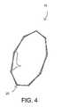
- FIG. 4is a perspective view of the support structure of FIG. 1 in a fully expanded state.
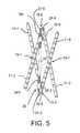
- FIG. 5is a perspective view of the support structure of FIG. 2 having a particular actuator mechanism.
- FIG. 6is a perspective view of the support structure of FIG. 2 having another particular actuator mechanism.
- FIG. 7is a perspective view of a particular support structure and control catheter assembly usable with the actuator mechanisms of FIGS. 5 and 6 .
- FIG. 8is a perspective view of a particular rotating prosthetic valve assembly.
- FIG. 9is a perspective view of the valve assembly of FIG. 8 while being closed.
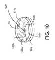
- FIG. 10is a perspective view of the valve assembly of FIG. 8 once completely closed.
- FIG. 11is a perspective view of the valve of FIGS. 8-10 in combination with the support structure of FIG. 1 .
- FIG. 12is a perspective view of the valve of FIG. 11 in the open position.
- FIG. 13is a perspective view of a traditional tissue valve mounted to the support structure of FIG. 1 .
- FIG. 14is a perspective view of the valve structure of FIG. 13 having a full inner skirt.
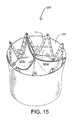
- FIG. 15is a perspective view of the valve structure of FIG. 13 having a full outer skirt.
- FIG. 16is a perspective view of the arrangement of strut members in a conical-shaped support structure configuration.
- FIG. 17is a perspective view of an hourglass-shaped support structure configuration.
- FIG. 18is a cross-sectional view of a heart, showing the valve of FIG. 8 in the open valve position, being used as a mitral valve replacement.
- FIG. 19is a cross-sectional view of a heart, showing the valve of FIG. 8 and a support structure, as a mitral valve replacement, in the closed valve position.
- FIG. 20is a cross-sectional view of a heart showing the valve of FIG. 8 in the closed valve position, being used as an aortic valve replacement.
- FIG. 21is a cross-sectional view of a heart showing the valve of FIG. 8 in the open valve position, being used as an aortic valve replacement.
- FIG. 22is a cross-sectional view of a heart showing the valve of FIG. 8 and a support structure as an aortic valve replacement, in the closed valve position.
- FIG. 23is a cross-sectional view of a heart, showing the valve of FIG. 8 and a support structure, as an aortic valve replacement, in the open valve position.
- FIG. 24is a cross-sectional view of a heart, showing the catheter deployment of a valve and a support structure as an aortic valve replacement, using the retrograde approach.
- FIG. 25is a perspective view of a support structure showing an expansion element and a mechanism.
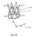
- FIG. 26is a perspective view of an expanded support structure with a compression element and mechanism.
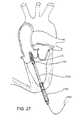
- FIG. 27is a cross-sectional view of a heart, showing the catheter deployment of a valve and a support structure as an aortic valve replacement, using the apical approach.
- FIG. 28is a cross-sectional view of a heart, showing the catheter deployment of a valve and a support structure as an aortic valve replacement, using the apical approach.
- Particular embodiments of the inventioninclude endoluminal support structures (stents) and prosthetic valves.
- FIG. 1is a perspective view of a particular endoluminal support structure.
- the support structure 10is a medical stent that includes a plurality of longitudinal strut members 11 interconnected by a plurality of swivel joints 15 .
- the swivel joints 15allow the interconnected strut members 11 to rotate relative to each other.
- the strut members 11are fabricated from a rigid or semi-rigid biocompatible material, such as plastics or other polymers and metal alloys, including stainless steel, tantalum, titanium, nickel-titanium (e.g. Nitinol), and cobalt-chromium (e.g. ELGILOY).
- the dimensions of each strutcan be chosen in accordance with its desired use.
- each strut memberis made from stainless steel, which is 0.005-0.020 inch thick. More particularly, each strut is 0.010 inch thick 300 series stainless steel.
- struts 11While all struts 11 are shown as being of uniform thickness, the thickness of a strut can vary across a strut, such as a gradual increase or decrease in thickness along the length of a strut. Furthermore, individual struts can differ in thickness from other individual struts in the same support structure.
- each strut member 11is bar shaped and has a front surface 11 f and a back surface 11 b .
- the strut memberscan however be of different geometries. For example, instead of a uniform width, the struts can vary in width along its length. Furthermore, an individual strut can have a different width than another strut in the same support structure. Similarly, the strut lengths can vary from strut to strut within the same support structure. The particular dimensions can be chosen based on the implant site.
- the strutscan be non-flat structures.
- the strutscan include a curvature, such as in a concave or convex manner in relationship to the inner diameter of the stent structure.
- the strutscan also be twisted.
- the nonflatness or flatness of the strutscan be a property of the material from which they are constructed.
- the strutscan exhibit shape-memory or heat-responsive changes in shape to the struts during various states. Such states can be defined by the stent in the compressed or expanded configuration.
- the strut members 11can have a smooth or rough surface texture.
- a pitted surfacecan provide tensile strength to the struts.
- roughness or pittingcan provide additional friction to help secure the support structure at the implant site and encourage irregular encapsulation of the support structure 10 by tissue growth to further stabilize the support structure 10 at the implant site over time.
- the stentcould be comprised of struts that are multiple members stacked upon one another.
- some strutscould include elongated members stacked upon one another in a multi-ply configuration, and other struts could be one-ply, composed of single-thickness members.
- Each strut member 11also includes a plurality of orifices 13 spaced along the length of the strut member 11 .
- the orificesare countersunk 17 to receive the head of a fastener.
- there are thirteen equally spaced orifices 13 along the length of each strut member 11but more or less orifices can be used.
- the orifices 13are shown as being of uniform diameter and uniform spacing along the strut member 11 , but neither is required.
- the strut members 11are arranged as a chain of four-bar linkages.
- the strut members 11are interconnected by swivelable pivot fasteners 25 , such as rivets, extending through aligned orifices 13 .
- swivelable pivot fasteners 25can be employed such as screws, bolts, ball-in-socket structures, nails, or eyelets, and that the fasteners can be integrally formed in the struts 11 such as a peened semi-sphere interacting with an indentation or orifice, or a male-female coupling.
- the orifices 13also provide an additional pathway for tissue growth-over to stabilize and encapsulate the support structure 10 over time.
- FIG. 2is a perspective view of a four strut section of the stent of FIG. 1 . As shown, two outer strut members 11 - 1 , 11 - 3 overlap two inner strut members 11 - 2 , 11 - 4 , with their back surfaces in communication with each other.
- first strut member 11 - 1is swivelably connected to the second strut member 11 - 1 by a middle swivel joint 15 - 1 using a rivet 25 - 1 , which utilizes orifices 13 that bisect the strut members 11 - 1 , 11 - 2 .
- the third strut member 11 - 3is swivelably connected to bisect the fourth strut member 11 - 4 by a middle swivel joint 15 - 7 using a rivet 25 - 7 .
- the middle swivel joints 15 - 1 , 15 - 7function as a scissor joint in a scissor linkage or mechanism.
- the resulting scissor armsare of equal length. It should also be understood that the middle joint 15 - 1 , 15 - 7 need not bisect the joined strut members, but can instead utilize orifices 13 offset from the longitudinal centers of the strut members resulting in unequal scissor arm lengths.
- the first strut member 11 - 1is swivelably connected to the third strut member 11 - 3 by a distal anchor swivel joint 15 - 5 , located near the distal ends of the strut members 11 - 1 , 11 - 3 .
- the first strut member 11 - 1is swivelably connected to the fourth strut member 11 - 4 by a proximal anchor swivel joint 15 - 3 , located near the proximal ends of the strut members 11 - 1 , 11 - 4 .
- the distal and proximal ends of the struts 11can be curved or twisted to provide a flush interface between the joined struts.
- the support structure 10( FIG. 1 ) is fabricated by linking together a serial chain of scissor mechanisms. The chain is then wrapped to join the last scissor mechanism with the first scissor mechanism in the chain. By actuating the linkage the links can be opened or closed, which results in expanding or compressing the stent 10 ( FIG. 1 ).
- the diameter of the stentcan be compressed for insertion through a biological lumen, such as an artery, to a selected position.
- the stentcan then be expanded to secure the stent at the selected location within the lumen.
- the stentcan be recompressed for removal from the body or for repositioning within the lumen.
- FIG. 3is a perspective view of a compressed support structure of FIG. 1 .
- the stent 10When compressed, the stent 10 is at its maximum length and minimum diameter.
- the maximum lengthis limited by the length of the strut members, which in a particular embodiment is 15 mm.
- the minimum diameteris limited by the width of the strut members, which in a particular embodiment is 0.052 inch.
- FIG. 4is a perspective view of the support structure of FIG. 1 in a fully expanded state.
- the fully expanded support structure 10forms a ring, which can be used as an annuloplasty ring.
- the compression of the stentwill enable the tissue to cinch.
- the devicecould be used to provide an individualized cinching of the tissue to increase the competency of a heart valve. This could be a useful treatment for mitral valve diseases, such as mitral regurgitation or mitral valve prolapse.
- the support structure 10can be implanted in a patient during an open operative procedure, a closed procedure will often be more desirable.
- the support structure 10can include an actuation mechanism to allow a surgeon to expand or compress the support structure from a location remote from the implant site. Due to the properties of a scissor linkage wrapped into a cylinder ( FIG. 1 ), actuation mechanisms can exert work to expand the stent diameter by either increasing the distance between neighboring scissor joints, and decreasing the distance between the anchor joints.
- FIG. 5is a perspective view of the support structure of FIG. 2 having a particular actuator mechanism.
- the actuator mechanism 30includes a dual-threaded rod 32 positioned on the inside of the support structure 10 ( FIG. 1 ). It should be understood, however, that the actuator mechanism 30 can instead be positioned on the outside of the support structure 10 . Whether positioned on the inside or outside, the actuator mechanism 30 operates in the same way.
- the rodincludes right-hand threads 34 R on its proximal end and left-hand threads 34 L on its distal end.
- the rod 32is mounted the anchor points 15 - 3 , 15 - 5 using a pair of threaded low-profile support mounts 35 - 3 , 35 - 5 .
- Each end of the rod 32is terminated by a hex head 37 - 3 , 37 - 5 for receiving a hex driver (not shown).
- a hex drivernot shown.
- rotating the rod 32 in one directionwill urge the anchor points 25 - 3 , 25 - 5 outwardly to compress the linkages while rotating the rod 32 in the opposite direction will urge the anchor points 25 - 3 , 25 - 5 inwardly to expand the linkages.
- FIG. 6is a perspective view of the support structure of FIG. 2 having another particular actuator mechanism.
- the actuator mechanism 30 ′includes a single-threaded rod 32 ′ positioned on the inside of the support structure 10 ( FIG. 1 ).
- the rod 32 ′includes threads 34 ′ on one of its ends.
- the rod 32 ′is mounted to low profile anchor points 15 - 3 , 15 - 5 using a pair of support mounts 35 ′- 3 , 35 ′- 5 , one of which is threaded to mate with the rod threads 34 ′.
- the unthreaded end of the rod 32 ′includes a retaining stop 39 ′ that bears against the support mount 35 ′- 5 to compress the support structure.
- Each end of the rod 32 ′is terminated by a hex head 37 ′- 3 , 37 ′- 5 for receiving a hex driver (not shown). Again, rotating the rod 32 ′ in one direction will urge the anchor points 25 - 3 , 25 - 5 outwardly to compress the linkages while rotating the rod 32 ′ in the opposite direction will urge the anchor points 25 - 3 , 25 - 5 inwardly to expand the linkages.
- a ratcheting mechanismcan be incorporated to be utilized during the sliding of one strut relative to the other.
- the stentcould lock at incremental diameters due to the interaction of features that are an integral part of each strut.
- An example of such featureswould be a male component (e.g. bumps) on one strut surface which mates with the female component (e.g. holes) on the surface of the neighboring strut surface, as the two struts slide pass one another.
- Such structurescould be fabricated to have an orientation, such that they incrementally lock the stent in the expanded configuration as the stent is expanded.
- Such a stentcould be expanded using a conventional balloon or other actuation mechanism described in this application.
- the actuator mechanismis controlled remotely by a surgeon.
- the support structure 10is implanted through a body lumen, such as the femoral artery using a tethered endoluminal catheter.
- the actuator mechanism 30can be controlled via the catheter.
- FIG. 7is a perspective view of a particular support structure and control catheter assembly usable with the actuator mechanisms of FIGS. 5 and 6 .
- the control catheter 40is dimensioned to be inserted with the support structure through a biological lumen, such as a human artery.
- the control catheter 40includes a flexible drive cable 42 having a driver 44 on its distal end that removably mates with a hex head 37 , 37 ′ of the actuator mechanism ( FIGS. 5 and 6 ).
- the proximal end of the cable 42includes a hex head 46 .
- the proximal hex head 46 of the cable 42is rotated by a surgeon, using a thumb wheel or other suitable manipulator (not shown). Rotation of the hex head 46 is transferred by the cable 42 to the driver head 44 to turn the actuator rod 30 , 30 ′ ( FIGS. 5 and 6 ).
- the cable 42is encased by a flexible outer sheath 48 .
- the distal end of the outer sheath 48includes a lip or protuberance 49 shaped to interface with the support structure 10 .
- the outer sheath lip 49interacts with the support structure 10 to counteract the resulting torque.
- the rodis self-locking to maintain the support structure in the desired diameter.
- the rod 32 , 32 ′has a diameter of 1.0 mm and a thread count of 240 turns/inch.
- the actuator mechanismcan be disposed within the thickness of the strut members, instead of inside or outside of the stent.
- worm gears or a rack and pinion mechanismcan be employed as known in the art.
- One of ordinary skill in the artshould recognize other endoluminal actuation techniques.
- the support structurecan be implanted during an open procedure, which may not require an external actuation mechanism.
- a particular embodimentsupports a prosthetic valve.
- the support structureis used in combination with a prosthetic valve, such as for an aortic valve replacement.
- FIG. 8is a perspective view of a particular rotating prosthetic valve assembly.
- the prosthetic valve 100comprises a three leaflet configuration shown in an open position.
- the leafletsare derived from a biocompatible material, such as animal pericardium (e.g. bovine, porcine, equine), human pericardium, chemically treated pericardium, gluteraldehyde-treated pericardium, tissue engineered materials, a scaffold for tissue engineered materials, autologous pericardium, cadaveric pericardium, Nitinol, polymers, plastics, PTFE, or any other material known in the art.
- animal pericardiume.g. bovine, porcine, equine
- human pericardiume.g. bovine, porcine, equine
- human pericardiume.g. bovine, porcine, equine
- human pericardiume.g. bovine, porcine, equine
- each leaflet 101 a , 101 b , 101 care attached to a stationary cylindrical member 105 and a non-stationary cylindrical member 107 .
- One side of each leaflet 101is attached to the non-stationary cylindrical member 107 .
- the opposing side of each leaflet 101is attached to the stationary cylindrical member 105 .
- the attachment of each leaflet 101is in a direction generally perpendicular to the longitudinal axis of the cylindrical members 105 , 107 .
- each leaflet 101is pliable, generally rectangular in shape, and has a 180 degree twist between its attachments to stationary member 105 and non-stationary member 107 .
- Each leaflet 101has an inner edge 102 and an outer edge 103 , with the edges 102 c , 103 c of one leaflet 101 c being referenced in the figure.
- the leafletscan be fabricated from either biological or non-biological materials, or a combination of both.
- One way to actuate the valve to closeis by utilizing the forces exerted by the normal blood flow or pressure changes of the cardiac cycle. More specifically, the heart ejects blood through the fully open valve in the direction of the arrow shown in FIG. 8 . Shortly thereafter, the distal or downstream blood pressure starts to rise relative to the proximal pressure across the valve, creating a backpressure on the valve.
- FIG. 9is a perspective view of the valve assembly of FIG. 8 while being closed. That backpressure along the direction of the arrow causes the axially displacement of the leaflets 101 and non-stationary member 107 towards the stationary cylindrical member 105 . As the leaflets 101 move from a vertical to horizontal plane relative to the longitudinal axis, a net counter-clockwise torque force is exerted on the non-stationary member 107 and leaflets 101 . The torque force exerts a centripetal force on the leaflets 101 .
- FIG. 10is a perspective view of the valve assembly of FIG. 8 once completely closed. Complete closure of the valve 100 occurs as the leaflets 101 displace to the center of the valve and the non-stationary cylindrical member 107 rests upon the stationary member 105 , as shown.
- valve 100 openingcan be understood by observing the reverse of the steps of valve closing, namely following the sequence of drawings from FIG. 10 to FIG. 8 .
- valve 100As an aortic valve replacement, it would remain closed as shown in FIG. 10 , until the heart enters systole.
- the blood pressure exerted on the valve's proximal sideis greater than the pressure on the distal side (downstream) of the closed valve.
- This pressure gradientcauses the leaflets 101 and non-stationary cylindrical member 107 to displace away from the stationary member 105 along the axial plane.
- the valve 100briefly assumes the half-closed transition state shown in FIG. 9 .
- the torque forcescause the leaflets 101 to rotate with the non-stationary member 107 around the longitudinal axis of the valve 100 . This, in turn, exerts a centrifugal force on each leaflet 101 .
- the leaflets 101undergo radial displacement away from the center, effectively opening the valve and allowing blood to flow away from the heart, in the direction shown by the arrow in FIG. 8 .
- the valvepassively functions to provide unidirectional blood flow by linking three forces.
- Axial, torque, and radial forcesare translated in a sequential and reversible manner, while encoding the directionality of prior motions.
- the axial force of blood flow and pressurecauses the displacement of the leaflets 101 and non-stationary members 107 relative to the stationary member 105 along the axial plane. This is translated into a rotational force on the leaflets 101 and non-stationary member 107 .
- the torque forcedisplaces the leaflets 101 towards or away from the center of the valve, along the radial plane, which closes or opens the valve 100 .
- the valve 100passively follows the pathway of opening or closing, depending on the direction of the axial force initially applied to the valve by the cardiac cycle.
- the stationary cylindrical member 105can secured and fixed in position at the implant site, while the non-stationary member 107 and distal ends of leaflets 101 are free to displace along the axial plane.
- the stationary member 105would be secured in the aortic root.
- FIG. 11is a perspective view of the valve of FIGS. 8-10 in combination with the support structure of FIG. 1 .
- the support structureenables the valve to be retrieved and repositioned in the body during use. This is important because serious complications and patient deaths have occurred due to malpositioning of valves at implant sites in the body, using the available stent-mounted valves. Valve malpositioning has resulted in massive paravalvular leakage, device migration, and coronary artery obstruction. Even though the majority of these complications may have been unavoidable and detected only at the time of the procedure, inability to reposition or retrieve the device made it impossible to reverse or mitigate these problems during the procedure.
- the support structureenables the valve to be readily retrieved and repositioned in the body. If following deployment, the valve is malpositioned or deemed dysfunctional, the support structure allows the valve to be readily repositioned and redeployed at a new implant site, or removed from the body entirely. By enabling the repositioning, redeployment or removal of malpositioned devices, the support structure could prevent serious complications and save lives.
- valve's stationary member 105is attached to the support structure 10 .
- the valve's nonstationary member 107is not attached to the support structure 10 . This enables the nonstationary member 107 to displace along the axial plane along with the leaflets 101 during valve opening or closing.
- the valve 100occupies a position that is closer to one end of the support structure 10 , as shown.
- FIG. 12is a perspective view of the valve of FIG. 11 in the open position.
- the non-stationary member 107is not attached to support structure 10 , and is thus free to displace along the axial plane, along with the leaflets 101 .
- non-stationary member 107 and the leaflets 101remain within the confines of the support structure 10 .
- the stented valve 110can be implanted during a closed procedure as described above. However, because of the operation of the non-stationary member within the body of the stent, the actuator mechanism to compress and expand the stent would not be disposed within the stent.
- valves described heremay be positioned in any of a number of different regions of the body, using any of a number of different procedures, including both open and closed procedures. Surgical, non-surgical, or minimally invasive procedures may be employed.
- the valvesmay be used in a mitral position.
- FIGS. 18 and 19each depict a cross-sectional view of the heart showing the implant in the mitral position.
- the implantmay be positioned in the mitral position using an open chest procedure ( FIG. 18 ) or a closed chest procedure ( FIG. 19 ).
- FIG. 18depicts the valve 100 of FIG. 8 in its open position, being used without a support structure as a mitral valve replacement. The direction of blood flow is shown by the arrow.
- FIG. 19depicts the valve 100 in its closed position, when it is mounted in the support structure 10 , as intended for a closed chest procedure.
- the stationary member 105 of the valve 100is secured to the implant site, and the non-stationary member 107 is free to displace with the leaflets 101 towards or away from the left ventricle.
- the valvesmay be used in an aortic position.
- the valvesmay be delivered using an open chest procedure or a closed chest procedure.
- FIGS. 20 and 21depict a cross-sectional view of a heart, where the valve 100 has been positioned at an aortic site using an open chest procedure.
- FIG. 20shows the valve 100 in a closed position
- FIG. 21shows the valve 100 in an open position.
- the heartis depicted as having a debrided aortic implant site, as in a conventional open chest implant aortic valve replacement.
- the valve 100is secured to the implant site by attachment of the stationary member 105 .
- the non-stationary member 107 and the leaflets 101are free to move in the axial plane.
- the arrow in FIG. 21indicates the direction of blood flow through the open valve.
- FIGS. 22 and 23also depict a cross-sectional view of a heart.
- the valve 100has been implanted at an aortic site in the heart using a closed chest procedure.
- the valve 100is mounted in the support structure 10 and is used to displace diseased leaflets at the aortic site.
- the valveIn FIG. 22 , the valve is in its closed position, while in FIG. 23 , the valve is in its open position.
- the stationary member 105is attached to the support structure 10 , which is attached to the implant site.
- the non-stationary member 107 and the leaflets 101are free to displace in the axial plane within the confines of the support structure 10 .
- the arrow in FIG. 23shows the direction of blood flow through the open valve.
- Different delivery methodsmay be used to implant the valves, including retrograde delivery methods, apical delivery methods, and antegrade delivery methods.
- FIG. 24shows a cross-sectional view of a heart, in which the retrograde delivery of the stented valve 110 as an aortic valve replacement is depicted.
- the valve 100is compressed in the support structure 10 .
- a catheter 2458is used to pass the valve 100 and support structure 10 into the femoral artery at the groin.
- the catheteris advanced to the aortic valve site under fluoroscopic guidance.
- the support structure 10is deployed at the site by pulling on an expansion wire 2460 . More specifically, as shown in FIG. 25 , the support structure 10 comprises upper and lower bars 2594 .
- An upper expansion element 2554may be displaced toward a lower expansion element 2556 by pulling on wire 2460 (which is attached to upper expansion element 2554 ), thereby causing a radial expansion of the device (large arrows).
- the catheter 2458which is attached to a lower bar 2594 of the support structure 10 , provides a counterforce to pulling on wire 2460 , effectively holding the support structure 10 in a fixed position during expansion of the support structure.
- the general principle of the mechanismis that applying an opposing axial load to any pair of opposing upper and lower ends of the bars 2594 of the device causes radial expansion of the device.
- the elements, such as upper expansion element 2554could be simplified further by being replaced by a simple pull wire exerting the same forces on the structure.
- FIG. 26shows an additional wire 2476 being employed in the device to enable the compression of the device, in case of malpositioning of the valve. More specifically, the pull wire 2476 is securely attached to one of the bars of the device, and looped completely around the lower aspect of the support structure 10 . Pulling on the free end of the wire 2476 displaces the ends of neighboring bars 2494 toward one another, and compresses the support structure 10 toward the center, narrowing its profile. A structure to provide counterforce, such as a catheter, would be useful to hold the support structure 10 in its intended implant site, as the wire 2476 is pulled back.
- valve 100 and the support structure 10 at the implant siteProper positioning of the valve 100 and the support structure 10 at the implant site is confirmed by observing valve function under fluoroscopy, as well as by the stabilization of hemodynamic parameters. After proper valve position is confirmed, the catheter 2458 and all wires are detached from the device and removed from the body. The retrograde approach may be used to deliver the device to the mitral position.
- FIG. 27depicts a cross-sectional view of a heart, showing the apical delivery of the device for aortic valve replacement.
- a small incisionis made in the chest wall, and a cannula 2780 is inserted in the left ventricle through the apex of the heart.
- the valve 100 and support structure 10are passed through the cannula on a catheter 2792 .
- a wire 2460is pulled to expand the device.
- a second wirecould be employed to compress the device ( FIG. 26 ).
- the devicecould then be reversibly expanded, compressed, re-positioned, and re-expanded, as previously described, to correct for malpositioning or malfunctioning of the valve.
- the apical approachcould be used for deployment of the valve into the mitral position.
- FIG. 28the antegrade delivery of the device using a closed chest procedure is depicted.
- a delivery proceduremay be used in aortic or mitral valve replacement.
- the valve 100 and support structure 10mounted on a catheter 2856 , are inserted into the femoral vein at the groin and advanced in the inferior vena cava and into right atrium. Under fluoroscopic guidance, the catheter is advanced across the septum and into the left atrium.
- the deviceis deployed at the implant site by pulling on wire 2460 . It could be compressed and re-positioned, if necessary, using the additional features and mechanisms described previously for the retrograde or apical approaches.
- valves described hereincould be mounted on a support structure for delivery into the body using a non-surgical or closed chest procedure.
- a valvecould be mounted on the support structure, based on a four bar linkage, as described in detail in this application.
- the support structurecould comprise a balloon-expandable support structure (e.g., Edwards' SAPIEN valve delivery system), a self-expanding support structure (e.g., the CoreValve ReValving system), or other available support structures.
- valve 100 described hereinis that there is sizable space between its leaflets and significantly less leaflet material in a given cross-sectional plane than in a conventional tissue valve. This allows the device to assume a relatively narrow profile, as it is compressed into a configuration suitable for closed chest or non-surgical implantation in the body. Additionally, the support structure 10 described herein eliminates the requirement for a balloon or sheath, thereby further reducing the device profile relative to other available stent-mounted valves. The device's relatively narrow profile enables the valve 100 to be more easily delivered to the implant site. Moreover, the decrease in device profile could widen the indications for using less-invasive routes in the body, such as the previously described retrograde approach. As a result, patients could recover from the procedure relatively rapidly, and there could be a reduced likelihood of serious complications and patient deaths.
- the support structure 10 described hereindoes not require a balloon for device expansion. Consequently, it avoids the risk of damage to the heart arising from undesirable backpressure inadvertently being exerted on the heart by a balloon.
- a balloonwhen a balloon is used for device expansion in the case of an aortic valve, the expanded balloon can completely obstruct the aorta and can impose an inadvertent backpressure on the heart (i.e., afterload).
- the device described hereincan help further avoid heart damage because the valve 100 functions immediately upon expansion of the support structure 10 , without having to wait for deflation of a balloon or unsheathing of the device.
- a tissue valvecan be draped on the support structure. Additional embodiments should be apparent to those of ordinary skill in the art.
- FIG. 13is a perspective view of a traditional tissue valve mounted to the support structure of FIG. 1 .
- a stented valve 120includes a prosthetic tissue valve 121 attached to a support structure 10 , such as that described above.
- the tissue valve 121includes three pliable semi-circular leaflets 121 a , 121 b , 121 c , which can be derived from biocompatible materials as noted with reference to FIG. 8 .
- Adjacent leafletsare attached in pairs to commissures 123 x , 123 y , 123 z on the support structure 10 .
- the commissures 123 x , 123 y , 123 zcorrespond with spaced-apart distal anchor points 13 x , 13 y , 13 z on the support structure 10 .
- the commissuresare attached the structure 10 via corresponding fasteners 25 at every third distal anchor point.
- the leaflet sidesare connected to the adjacent diagonal struts. That is, the sides of the first leaflet 121 a are sutured to the struts 11 -Xa and 11 -Za, respectively; the sides of the second leaflet 121 b are sutured to the struts 11 -Xb and 11 -Yb, respectively; and the sides of the third leaflet 121 c are sutured to the struts 11 -Yc and 11 -Zc, respectively. Those sutures end at the scissor pivot points on the diagonal struts.
- neighboring struts 11are attached to one another in a manner that creates multiple arches 128 at the ends of the stent.
- Posts for leaflet attachment, or commissuresare formed by attaching neighboring leaflet to each of the struts that define a suitable arch 128 x , 128 y , 128 z .
- the commissuresare formed by three equi-distance arches 128 x , 128 y , 128 z in the stent.
- the angled orientation of a strut in relationship to its neighboring strutenables the leaflets 121 a , 121 b , 121 c to be attached to the stent in an triangular configuration.
- This triangular configurationsimulates the angled attachment of the native aortic leaflet.
- thiscreates an anatomical structure between leaflets, known as the inter-leaflet trigone. Because the anatomical inter-leaflet trigone is believed to offer structural integrity and durability to the native aortic leaflets in humans, it is advantageous to simulate this structure in a prosthetic valve.
- One method of attachment of the leaflets to the strutsis to sandwich the leaflet between a multi-ply strut. The multiple layers are then held together by sutures. Sandwiching the leaflets between the struts helps to dissipate the forces on leaflets and prevent the tearing of sutures through the leaflets.
- each leaflet 121 a , 121 b , 121 cis sutured annularly across the intermediate strut members as shown by a leaflet seam.
- the remaining open spaces between the strutsare draped by a biocompatible skirt 125 to help seal the valve against the implant site and thus limit paravalvular leakage.
- the skirt 125is shaped to cover those portions of the stent below and between the valve leaflets.
- the skirt 125 at the base of the valveis a thin layer of material that lines the stent wall.
- the skirt materialcan be pericardial tissue, polyester, PTFE, or other material or combinations of materials suitable for accepting tissue in growth, including chemically treated materials to promote tissue growth or inhibit infection.
- the skirt layerfunctions to reduce or eliminate leakage around the valve, or “paravalvular leak”. To that end, there are a number of ways to attach the skirt material layer to the stent, including:
- FIG. 14is a perspective view of the valve structure of FIG. 13 having a full inner skirt.
- a stented valve 120 ′includes a prosthetic tissue valve 121 ′ having three leaflets 121 a ′, 121 b ′, 121 c ′ attached to a support structure 10 .
- a skirt layer 125 ′covers the interior surface of the stent 10 . As such, the valve leaflets 121 a ′, 121 b ′, 121 c ′ are sutured to the skirt layer 125 ′.
- FIG. 15is a perspective view of the valve structure of FIG. 13 having a full outer skirt.
- a stented valve 120 ′′includes a prosthetic tissue valve 121 ′′ having three leaflets 121 a ′′, 121 b ′′, 121 c ′′ attached to a support structure 10 , such as that described in FIG. 13 .
- a skirt layer 125 ′′covers the exterior surface of the stent 10 .
- tissue valve structures 120 , 120 ′, 120 ′′can also be implanted during a closed procedure as described above. However, the actuator mechanism to compress and expand the stent would be attached to avoid the commissure points and limit damage to the skirt layer 125 , 125 ′, 125 ′′, such as by mounting the actuator mechanism on the outer surface of the stent 10 .
- FIG. 16is a perspective view of the arrangement of strut members in a conical-shaped support structure configuration.
- the strut members 11are arranged as shown in FIG. 2 , except that the middle scissor pivots do not bisect the struts.
- the middle scissor pivotse.g. 15 ′- 1 , 15 ′- 7
- the joined strut memberse.g. 11 ′- 1 , 11 ′- 2 and 11 ′- 3 , 11 ′ 4
- the resulting support structureWhen fully assembled, the resulting support structure thus conforms to a conical shape when expanded.
- the stent 10 ′is shown with a single-threaded actuator rod 32 ′ ( FIG. 6 ), but it is not a required element for this stent embodiment.
- the stent 10 ′can also assume a cone shape in its expanded configuration by imposing a convex or concave curvature to the individual strut members 11 that comprise the stent 10 ′. This could be achieved by using a material with memory, such as shape-memory or temperature sensitive Nitinol.
- a valvecan be orientated in the cone-shaped stent 10 ′ such that the base of the valve was either in the narrower portion of the cone-shaped stent, with the nonbase portion of the valve in the wider portion of the cone.
- the base of the valvecan be located in the widest portion of the stent with the non-base portion of the valve in the less-wide portion of the stent.
- a cone-shaped stent 10 ′ in the bodycan be either towards or away from the stream of blood flow.
- the stentcould be orientated in either direction, in relationship to the axial plane.
- FIG. 17is a perspective view of an hourglass-shaped support structure configuration.
- the circumference around the middle pivot points 15 ′′- 1 , 15 ′′- 7 , 15 ′′- 9 (the waist)is less than the circumference at either end of the stent 10 ′′.
- the hourglass shaped support structure 10 ′′is achieved by reducing the number of strut members 11 ′′ to six and shortening the strut members 11 ′′ in comparison to prior embodiments. As a result of the shortening, there are fewer orifices 13 ′′ per strut member 11 ′′. Because of the strut number and geometry, each strut member 11 ′′ includes a twist at points 19 ′′ along there longitudinal planes. The twists provide a flush interface between joined strut 15 ′′- 3 .
- An hourglass stent configurationcould also be achieved by imposing concave or convex curvatures in individual bars 11 ′′.
- the curvaturecould be a property of the materials (e.g. shape-memory or heat-sensitive Nitinol).
- the curvaturecould be absent in the compressed stent state and appear when the stent is in its expanded state.
- any of the above-described support structurescan be extended beyond the anchor joints at either of both ends of the stent.
- additional stent lengths and geometriescan be fabricated.
- an hourglass-shaped stentcould be achieved by joining two cone-shaped stents at their narrow ends.
- the hourglass shapecan also be modified by assembling the middle scissor pivots off center as shown in FIG. 14 .
- the deviceallows the user to advert the serious complications that can occur during percutaneous heart valve implantation. Because the device is retrievable and re-positionable during implantation into the body, the surgeon can avoid serious complications due to valve malpositioning or migration during implantation. Examples of these complications include occlusion of the coronary arteries, massive paravalvular leakage, or arrthymias.
- the devicecan also decrease vascular access complications because of the device's narrow insertion profile.
- the device's profileis low, in part, due to its unique geometry, which allows neighboring struts in the stent to overlap during stent compression.
- the device's low profileis further augmented by eliminating the necessity for a balloon or a sheath.
- the device's narrow profileoffers the advantage of widening the vascular access route options in patients. For instance, the device can enable the delivery of the prosthetic valve through an artery in the leg in a patient whom would have previously been committed to a more invasive approach through the chest wall. The device therefore aims to decrease complications associated with the use of large profile devices in patients with poor vascular access.
- the tissue valve embodimentscan offer improved durability by allowing for attachment of the leaflets to flexible commissural posts.
- the flexible postsallow dissipation of the stress and strain imposed on the leaflet by the cardiac cycle.
- the use of multi-ply strutsenables the leaflets to be sandwiched in between the struts, which re-enforces the leaflet attachments and prevents tearing of sutures.
- the valvefurther assumes a desirable leaflet morphology, which further reduces the stress and strain on leaflets. Namely, the angled leaflet attachment to the stent is similar to the native human aortic valve's inter-leaflet trigone pattern. These properties significantly improve the longevity of percutaneous heart valve replacement therapies.
- the devicecould reduce or eliminate arrthymia complications due to the incremental expansion or compression of the stent.
- the stentcan employ a screw mechanism for deployment, which enables the stent to self-lock or un-lock at all radii. This enables more controlled deployment and the potential for individualizing the expansion or compression of the device in each patient. Because the expansion or compression of the device is reversible at any stage during the procedure, the surgeon can easily reverse the expansion of the device to relieve an arrythmia. In addition, if an arrythmia is detected during implantation, the device can be repositioned to further eliminate the problem.
- the devicecan reduce or eliminate paravalvular leak due to the device's ability to be accurately positioned, and re-positioned, if necessary. That can considerably decrease the occurrence and severity of paravalular leaks.
- the deviceeliminates balloon-related complications.
- the screw mechanism of deploymentexploits the mechanical advantage of a screw. This provides for forceful dilation of the stent.
- the lever arms created by the pivoting of the struts in the scissor linkage of the stenttransmits a further expansion force to the stent.
- the stentis expanded without the need for a balloon.
- the ability of the device to be forcefully dilatedreduces or eliminates the need for pre- or postballooning during the implantation procedure in patients.
- the devicehas more predictable and precise positioning in the body because the difference between the height of the stent in the compressed and expanded position is small. This “reduced foreshortening” helps the surgeon to position the device in the desirable location in the body. The ability to re-position the device in the body further confers the ability to precisely position the device in each individual.
- the deviceenables a wider population of patients to be treated by a less invasive means for valve replacement.
- the deviceenables patients with co-morbidites, whom are not candidates for open chest surgical valve replacement, to be offered a treatment option.
- the device's ability to assume a narrow profilealso enables patients who were previously denied treatment due to poor vascular access (e.g. tortuous, calcified, or small arteries), to be offered a treatment option.
- the durability of the valveshould expand the use of less-invasive procedures to the population of otherwise healthy patients, whom would otherwise be candidates for open chest surgical valve replacement.
- the devicecan also provide a less invasive treatment to patients with degenerative prosthesis from a prior implant, by providing for a “valve-in-valve” procedure.
- the devicecould be accurately positioned inside the failing valve, without removing the patient's degenerative prosthesis. It would help the patient by providing a functional valve replacement, without a “re-do” operation and its associated risks.
Landscapes
- Health & Medical Sciences (AREA)
- Engineering & Computer Science (AREA)
- Biomedical Technology (AREA)
- Cardiology (AREA)
- Oral & Maxillofacial Surgery (AREA)
- Transplantation (AREA)
- Heart & Thoracic Surgery (AREA)
- Vascular Medicine (AREA)
- Life Sciences & Earth Sciences (AREA)
- Animal Behavior & Ethology (AREA)
- General Health & Medical Sciences (AREA)
- Public Health (AREA)
- Veterinary Medicine (AREA)
- Prostheses (AREA)
Abstract
Description
- the skirt layer can be on the inside or the outside of the stent;
- the skirt layer can occupy the lower portion of the stent;
- the skirt layer can occupy the lower and upper portion of the stent;
- the skirt layer can occupy only the upper portion of the stent;
- the skirt layer can occupy the area between the struts that define the commissure posts;
- the skirt layer can be continuous with the leaflet material;
- the skirt layer can be sutured to the struts or a multitude of sites; or
- the skirt layer can be secured to the lower portion of the stent, and pulled or pushed up to cover the outside of the stent during the deployment in the body.
Claims (29)
Priority Applications (1)
| Application Number | Priority Date | Filing Date | Title |
|---|---|---|---|
| US13/069,037US9039756B2 (en) | 2008-07-21 | 2011-03-22 | Repositionable endoluminal support structure and its applications |
Applications Claiming Priority (4)
| Application Number | Priority Date | Filing Date | Title |
|---|---|---|---|
| US8248908P | 2008-07-21 | 2008-07-21 | |
| PCT/US2009/051324WO2010011699A2 (en) | 2008-07-21 | 2009-07-21 | Repositionable endoluminal support structure and its applications |
| US12/761,295US8226707B2 (en) | 2008-07-21 | 2010-04-15 | Repositionable endoluminal support structure and its applications |
| US13/069,037US9039756B2 (en) | 2008-07-21 | 2011-03-22 | Repositionable endoluminal support structure and its applications |
Related Parent Applications (1)
| Application Number | Title | Priority Date | Filing Date |
|---|---|---|---|
| US12/761,295ContinuationUS8226707B2 (en) | 2008-07-21 | 2010-04-15 | Repositionable endoluminal support structure and its applications |
Publications (2)
| Publication Number | Publication Date |
|---|---|
| US20110230956A1 US20110230956A1 (en) | 2011-09-22 |
| US9039756B2true US9039756B2 (en) | 2015-05-26 |
Family
ID=46208220
Family Applications (1)
| Application Number | Title | Priority Date | Filing Date |
|---|---|---|---|
| US13/069,037Active2031-09-07US9039756B2 (en) | 2008-07-21 | 2011-03-22 | Repositionable endoluminal support structure and its applications |
Country Status (1)
| Country | Link |
|---|---|
| US (1) | US9039756B2 (en) |
Cited By (23)
| Publication number | Priority date | Publication date | Assignee | Title |
|---|---|---|---|---|
| US20130046373A1 (en)* | 2010-06-24 | 2013-02-21 | Syntheon Cardiology, Llc | Actively Controllable Stent, Stent Graft, Heart Valve and Method of Controlling Same |
| US20170056172A1 (en)* | 2003-12-23 | 2017-03-02 | Boston Scientific Scimed, Inc. | Methods and apparatus for endovascularly replacing a heart valve |
| US10238514B2 (en) | 2011-10-21 | 2019-03-26 | Edwards Lifesciences Cardiaq Llc | Actively controllable stent, stent graft, heart valve and method of controlling same |
| US10507097B2 (en) | 2006-07-31 | 2019-12-17 | Edwards Lifesciences Cardiaq Llc | Surgical implant devices and methods for their manufacture and use |
| US10568732B2 (en) | 2009-07-02 | 2020-02-25 | Edwards Lifesciences Cardiaq Llc | Surgical implant devices and methods for their manufacture and use |
| US10687968B2 (en) | 2006-07-31 | 2020-06-23 | Edwards Lifesciences Cardiaq Llc | Sealable endovascular implants and methods for their use |
| US10874508B2 (en) | 2011-10-21 | 2020-12-29 | Edwards Lifesciences Cardiaq Llc | Actively controllable stent, stent graft, heart valve and method of controlling same |
| US10993805B2 (en) | 2008-02-26 | 2021-05-04 | Jenavalve Technology, Inc. | Stent for the positioning and anchoring of a valvular prosthesis in an implantation site in the heart of a patient |
| US11065138B2 (en) | 2016-05-13 | 2021-07-20 | Jenavalve Technology, Inc. | Heart valve prosthesis delivery system and method for delivery of heart valve prosthesis with introducer sheath and loading system |
| US11185405B2 (en) | 2013-08-30 | 2021-11-30 | Jenavalve Technology, Inc. | Radially collapsible frame for a prosthetic valve and method for manufacturing such a frame |
| US11197754B2 (en) | 2017-01-27 | 2021-12-14 | Jenavalve Technology, Inc. | Heart valve mimicry |
| US11285002B2 (en) | 2003-12-23 | 2022-03-29 | Boston Scientific Scimed, Inc. | Methods and apparatus for endovascularly replacing a heart valve |
| US11337800B2 (en) | 2015-05-01 | 2022-05-24 | Jenavalve Technology, Inc. | Device and method with reduced pacemaker rate in heart valve replacement |
| US11344408B2 (en)* | 2016-12-06 | 2022-05-31 | Edwards Lifesciences Corporation | Mechanically expanding heart valve and delivery apparatus therefor |
| US11357624B2 (en) | 2007-04-13 | 2022-06-14 | Jenavalve Technology, Inc. | Medical device for treating a heart valve insufficiency |
| US11517431B2 (en) | 2005-01-20 | 2022-12-06 | Jenavalve Technology, Inc. | Catheter system for implantation of prosthetic heart valves |
| US11564794B2 (en) | 2008-02-26 | 2023-01-31 | Jenavalve Technology, Inc. | Stent for the positioning and anchoring of a valvular prosthesis in an implantation site in the heart of a patient |
| US11589981B2 (en) | 2010-05-25 | 2023-02-28 | Jenavalve Technology, Inc. | Prosthetic heart valve and transcatheter delivered endoprosthesis comprising a prosthetic heart valve and a stent |
| US11998465B2 (en) | 2015-05-20 | 2024-06-04 | Elemental Portfolio, Llc | Radial expansion and contraction features of medical devices |
| US12121461B2 (en) | 2015-03-20 | 2024-10-22 | Jenavalve Technology, Inc. | Heart valve prosthesis delivery system and method for delivery of heart valve prosthesis with introducer sheath |
| US12171658B2 (en) | 2022-11-09 | 2024-12-24 | Jenavalve Technology, Inc. | Catheter system for sequential deployment of an expandable implant |
| US12364596B2 (en) | 2011-10-21 | 2025-07-22 | Edwards Lifesciences Cardiaq Llc | Actively controllable stent, stent graft, heart valve and method of controlling same |
| US12414854B2 (en) | 2010-05-20 | 2025-09-16 | Jenavalve Technology, Inc. | Catheter system for introducing an expandable stent into the body of a patient |
Families Citing this family (37)
| Publication number | Priority date | Publication date | Assignee | Title |
|---|---|---|---|---|
| US9814611B2 (en) | 2007-07-31 | 2017-11-14 | Edwards Lifesciences Cardiaq Llc | Actively controllable stent, stent graft, heart valve and method of controlling same |
| CN102245129B (en) | 2008-07-21 | 2015-03-18 | 詹妮弗·K·怀特 | Repositionable intraluminal support structures and their applications |
| US9039756B2 (en) | 2008-07-21 | 2015-05-26 | Jenesis Surgical, Llc | Repositionable endoluminal support structure and its applications |
| WO2014176361A1 (en)* | 2013-04-25 | 2014-10-30 | Reva Medical, Inc. | Expandable deformable slide and lock stent |
| JP6184963B2 (en) | 2011-10-05 | 2017-08-23 | ボストン サイエンティフィック サイムド,インコーポレイテッドBoston Scientific Scimed,Inc. | Thin seal material for replacement heart valve and method of forming the same |
| EP2802290B1 (en)* | 2012-01-10 | 2018-07-11 | Jenesis Surgical, LLC | Articulated support structure with secondary strut features |
| WO2013112586A1 (en)* | 2012-01-24 | 2013-08-01 | Smith & Nephew, Inc. | Porous structure and methods of making same |
| WO2013184895A1 (en)* | 2012-06-07 | 2013-12-12 | Boston Scientific Scimed, Inc. | Apparatus for replacing a native heart valve |
| US10849755B2 (en) | 2012-09-14 | 2020-12-01 | Boston Scientific Scimed, Inc. | Mitral valve inversion prostheses |
| US10543088B2 (en) | 2012-09-14 | 2020-01-28 | Boston Scientific Scimed, Inc. | Mitral valve inversion prostheses |
| CA2892521C (en) | 2012-12-31 | 2019-05-21 | Edwards Lifesciences Corporation | Surgical heart valves adapted for post-implant expansion |
| US10543085B2 (en) | 2012-12-31 | 2020-01-28 | Edwards Lifesciences Corporation | One-piece heart valve stents adapted for post-implant expansion |
| CN107184292B (en) | 2013-03-13 | 2020-07-10 | 爱德华兹生命科学卡迪尔克有限责任公司 | Articulating commissure valve stents and methods |
| GB201307965D0 (en)* | 2013-05-02 | 2013-06-12 | Cook Medical Technologies Llc | Vascular plug |
| GB2519932B (en)* | 2013-08-13 | 2015-10-21 | Cook Medical Technologies Llc | Implantable flow adjuster |
| CR20160240A (en)* | 2013-11-11 | 2016-08-04 | Edwards Lifesciences Cardiaq Llc | SYSTEMS AND METHODS FOR THE MANUFACTURE OF THE FRAME OF A CANNULA |
| US9180005B1 (en)* | 2014-07-17 | 2015-11-10 | Millipede, Inc. | Adjustable endolumenal mitral valve ring |
| US20160067040A1 (en)* | 2014-09-09 | 2016-03-10 | Boston Scientific Scimed, Inc. | Valve locking mechanism |
| US9848983B2 (en) | 2015-02-13 | 2017-12-26 | Millipede, Inc. | Valve replacement using rotational anchors |
| US10327892B2 (en) | 2015-08-11 | 2019-06-25 | Boston Scientific Scimed Inc. | Integrated adaptive seal for prosthetic heart valves |
| US10335275B2 (en) | 2015-09-29 | 2019-07-02 | Millipede, Inc. | Methods for delivery of heart valve devices using intravascular ultrasound imaging |
| GB201615219D0 (en) | 2016-09-07 | 2016-10-19 | Vascutek Ltd And Univ Medical Center Hamburg-Eppendorf (Uke) | Hybrid prosthesis and delivery system |
| GB2554670B (en) | 2016-09-30 | 2022-01-05 | Vascutek Ltd | A vascular graft |
| US10548731B2 (en) | 2017-02-10 | 2020-02-04 | Boston Scientific Scimed, Inc. | Implantable device and delivery system for reshaping a heart valve annulus |
| GB2562065A (en) | 2017-05-02 | 2018-11-07 | Vascutek Ltd | Endoprosthesis |
| GB201707929D0 (en) | 2017-05-17 | 2017-06-28 | Vascutek Ltd | Tubular medical device |
| US11026785B2 (en) | 2017-06-05 | 2021-06-08 | Edwards Lifesciences Corporation | Mechanically expandable heart valve |
| US10869759B2 (en) | 2017-06-05 | 2020-12-22 | Edwards Lifesciences Corporation | Mechanically expandable heart valve |
| IL254099B (en)* | 2017-08-22 | 2021-02-28 | Geonovation Medical Tech Ltd | Foldable one-way valve prosthesis |
| GB201715658D0 (en) | 2017-09-27 | 2017-11-08 | Vascutek Ltd | An endoluminal device |
| EP3758651B1 (en) | 2018-02-26 | 2022-12-07 | Boston Scientific Scimed, Inc. | Embedded radiopaque marker in adaptive seal |
| USD944398S1 (en) | 2018-06-13 | 2022-02-22 | Edwards Lifesciences Corporation | Expanded heart valve stent |
| GB201820898D0 (en) | 2018-12-20 | 2019-02-06 | Vascutek Ltd | Stent device |
| US11439504B2 (en) | 2019-05-10 | 2022-09-13 | Boston Scientific Scimed, Inc. | Replacement heart valve with improved cusp washout and reduced loading |
| CA3142969A1 (en)* | 2019-08-12 | 2021-02-18 | Edwards Lifesciences Corporation | Prosthetic heart valves |
| CN112599185B (en)* | 2020-09-21 | 2022-04-12 | 北京交通大学 | Dual-mode scaling mechanism |
| CN113229995A (en)* | 2021-04-08 | 2021-08-10 | 温州医科大学附属第二医院(温州医科大学附属育英儿童医院) | Self-expanding intrabody absorption biliary tract stent |
Citations (75)
| Publication number | Priority date | Publication date | Assignee | Title |
|---|---|---|---|---|
| US3548417A (en) | 1967-09-05 | 1970-12-22 | Ronnie G Kischer | Heart valve having a flexible wall which rotates between open and closed positions |
| US4289123A (en) | 1980-03-31 | 1981-09-15 | Dunn Harold K | Orthopedic appliance |
| US5122154A (en) | 1990-08-15 | 1992-06-16 | Rhodes Valentine J | Endovascular bypass graft |
| US5171278A (en) | 1991-02-22 | 1992-12-15 | Madhavan Pisharodi | Middle expandable intervertebral disk implants |
| JPH072396U (en) | 1993-06-15 | 1995-01-13 | 株式会社豊田自動織機製作所 | Forklift pusher device |
| WO1995013033A1 (en) | 1993-11-08 | 1995-05-18 | Lazarus Harrison M | Intraluminal vascular graft and method |
| US5503497A (en) | 1994-09-19 | 1996-04-02 | Op-D-Op, Inc. | Ratchet link |
| US5545214A (en) | 1991-07-16 | 1996-08-13 | Heartport, Inc. | Endovascular aortic valve replacement |
| US5593417A (en) | 1995-11-27 | 1997-01-14 | Rhodes; Valentine J. | Intravascular stent with secure mounting means |
| US5643339A (en) | 1992-08-06 | 1997-07-01 | William Cook Europe A/S | Prosthetic device for sustaining a blood-vessel or hollow organ lumen |
| US5735842A (en) | 1995-09-11 | 1998-04-07 | St. Jude Medical, Inc. | Low profile manipulators for heart valve prostheses |
| US5776181A (en) | 1995-07-25 | 1998-07-07 | Medstent Inc. | Expandable stent |
| US5827321A (en) | 1997-02-07 | 1998-10-27 | Cornerstone Devices, Inc. | Non-Foreshortening intraluminal prosthesis |
| WO1999033414A1 (en) | 1997-12-29 | 1999-07-08 | Ivan Vesely | System for minimally invasive insertion of a bioprosthetic heart valve |
| US5968091A (en) | 1996-03-26 | 1999-10-19 | Corvita Corp. | Stents and stent grafts having enhanced hoop strength and methods of making the same |
| US6063113A (en) | 1995-06-13 | 2000-05-16 | William Cook Europe Aps | Device for implantation in a vessel or hollow organ lumen |
| JP3071573U (en) | 2000-03-07 | 2000-09-14 | 直樹 杉山 | Containers and components using bags of a wide range of sizes |
| US6146394A (en) | 1998-03-13 | 2000-11-14 | Cardiothoracic Systems, Inc. | Vascular clamp and method for using the same |
| US6183517B1 (en) | 1998-12-16 | 2001-02-06 | Loubert Suddaby | Expandable intervertebral fusion implant and applicator |
| US6245102B1 (en) | 1997-05-07 | 2001-06-12 | Iowa-India Investments Company Ltd. | Stent, stent graft and stent valve |
| US6261318B1 (en) | 1995-07-25 | 2001-07-17 | Medstent Inc. | Expandable stent |
| US6348061B1 (en) | 2000-02-22 | 2002-02-19 | Powermed, Inc. | Vessel and lumen expander attachment for use with an electromechanical driver device |
| WO2002049540A2 (en) | 2000-12-21 | 2002-06-27 | The Cleveland Clinic Foundation | Bioprosthetic cardiovascular valve system |
| US6454799B1 (en) | 2000-04-06 | 2002-09-24 | Edwards Lifesciences Corporation | Minimally-invasive heart valves and methods of use |
| US6475237B2 (en) | 1999-05-03 | 2002-11-05 | William J. Drasler | Intravascular hinge stent |
| US20030040791A1 (en) | 2001-08-22 | 2003-02-27 | Oktay Hasan Semih | Flexible MEMS actuated controlled expansion stent |
| WO2003047468A1 (en) | 2001-10-11 | 2003-06-12 | Percutaneous Valve Technologies | Implantable prosthetic valve |
| US6596021B1 (en) | 1999-10-26 | 2003-07-22 | Biotronik Mess -Und Therapiegeraete Gmbh & Co. Ingenieurbuero Berlin | Stent |
| WO2003075797A2 (en) | 2002-03-14 | 2003-09-18 | Angiomed Gmbh & Co. Medizintechnik Kg | Mri compatible stent and method of manufacturing the same_______ |
| US6666885B2 (en) | 1999-04-16 | 2003-12-23 | Carbomedics Inc. | Heart valve leaflet |
| US6685737B1 (en) | 2000-10-31 | 2004-02-03 | Advanced Cardiovascular Systems, Inc. | Endoluminal stent cross section for optimum biocompatibility |
| US6872226B2 (en) | 2001-01-29 | 2005-03-29 | 3F Therapeutics, Inc. | Method of cutting material for use in implantable medical device |
| US20050137688A1 (en) | 2003-12-23 | 2005-06-23 | Sadra Medical, A Delaware Corporation | Repositionable heart valve and method |
| WO2005102015A2 (en) | 2004-04-23 | 2005-11-03 | 3F Therapeutics, Inc. | Implantable prosthetic valve |
| US20050283231A1 (en) | 2004-06-16 | 2005-12-22 | Haug Ulrich R | Everting heart valve |
| US7007396B2 (en) | 2003-05-29 | 2006-03-07 | Plc Medical Systems, Inc. | Replacement heart valve sizing device |
| US7041132B2 (en) | 2002-08-16 | 2006-05-09 | 3F Therapeutics, Inc, | Percutaneously delivered heart valve and delivery means thereof |
| US20060111772A1 (en) | 2002-08-06 | 2006-05-25 | Icon Medical Corp. | Stent with micro-latching hinge joints |
| US7056338B2 (en) | 2003-03-28 | 2006-06-06 | Conor Medsystems, Inc. | Therapeutic agent delivery device with controlled therapeutic agent release rates |
| WO2006111772A2 (en) | 2005-04-22 | 2006-10-26 | Peter Lenighan | Improvements to showers and baths |
| WO2006116761A2 (en) | 2005-04-27 | 2006-11-02 | Stout Medical Group, L.P. | Expandable support device and methods of use |
| US7186265B2 (en) | 2003-12-10 | 2007-03-06 | Medtronic, Inc. | Prosthetic cardiac valves and systems and methods for implanting thereof |
| US20080004696A1 (en) | 2006-06-29 | 2008-01-03 | Valvexchange Inc. | Cardiovascular valve assembly with resizable docking station |
| WO2008015257A2 (en) | 2006-08-02 | 2008-02-07 | Syntach Ag | Luminal implant with large expansion ratio |
| US7329279B2 (en) | 2003-12-23 | 2008-02-12 | Sadra Medical, Inc. | Methods and apparatus for endovascularly replacing a patient's heart valve |
| WO2008051428A2 (en) | 2006-10-23 | 2008-05-02 | Valvexchange Inc. | Cardiovascular valve and assembly |
| US7374571B2 (en) | 2001-03-23 | 2008-05-20 | Edwards Lifesciences Corporation | Rolled minimally-invasive heart valves and methods of manufacture |
| US7381219B2 (en) | 2003-12-23 | 2008-06-03 | Sadra Medical, Inc. | Low profile heart valve and delivery system |
| US7402169B2 (en) | 1998-03-04 | 2008-07-22 | Boston Scientific Scimed, Inc. | Stent having variable properties and method of its use |
| WO2008088835A1 (en) | 2007-01-18 | 2008-07-24 | Valvexchange Inc. | Tools for removal and installation of exchangeable cardiovascular valves |
| US7404823B2 (en) | 2005-10-31 | 2008-07-29 | Boston Scientific Scimed, Inc. | Stent configurations |
| EP1671608B1 (en) | 2004-12-16 | 2008-07-30 | ValveXchange Inc. | Cardiovascular valve assembly |
| US20080183275A1 (en) | 2007-01-26 | 2008-07-31 | Eric Schmid | Circumferentially nested expandable device |
| US7429268B2 (en) | 2004-12-08 | 2008-09-30 | Innovational Holdings, Llc | Expandable medical device with differential hinge performance |
| US7431732B2 (en) | 2001-01-15 | 2008-10-07 | Terumo Kabushiki Kaisha | Stent with waved connecting members |
| US7438721B2 (en) | 2003-04-25 | 2008-10-21 | Medtronic Vascular, Inc. | Universal modular stent graft assembly to accommodate flow to collateral branches |
| US7458985B2 (en) | 2003-01-27 | 2008-12-02 | Frank Madda | Spiral stent assembly |
| US7479158B2 (en) | 2004-02-20 | 2009-01-20 | Boston Scientific Scimed, Inc. | Stent with nested flexible connectors for flexibility and crimpability |
| US7491227B2 (en) | 2003-06-16 | 2009-02-17 | Boston Scientific Scimed, Inc. | Coiled-sheet stent with flexible mesh design |
| US20090054969A1 (en) | 2003-12-23 | 2009-02-26 | Amr Salahieh | Repositionable Heart Valve and Method |
| WO2009026272A1 (en) | 2007-08-21 | 2009-02-26 | Valvexchange Inc. | Method and apparatus for prosthetic valve removal |
| US7500986B2 (en) | 2002-07-11 | 2009-03-10 | Medtronic Vascular, Inc. | Expandable body having deployable microstructures and related methods |
| US7500988B1 (en) | 2000-11-16 | 2009-03-10 | Cordis Corporation | Stent for use in a stent graft |
| US20090082844A1 (en) | 2007-09-26 | 2009-03-26 | Boston Scientific Corporation | System and method of pivoted stent deployment |
| US7510570B1 (en) | 1994-02-09 | 2009-03-31 | Boston Scientific Scimed, Inc. | Bifurcated endoluminal prosthesis |
| WO2009070180A1 (en) | 2007-11-30 | 2009-06-04 | Reva Medical, Inc. | Axially-radially nested expandable device |
| US20090210052A1 (en) | 2006-06-20 | 2009-08-20 | Forster David C | Prosthetic heart valves, support structures and systems and methods for implanting same |
| US7582110B2 (en) | 2004-04-13 | 2009-09-01 | Cook Incorporated | Implantable frame with variable compliance |
| US7591848B2 (en) | 2006-04-06 | 2009-09-22 | Medtronic Vascular, Inc. | Riveted stent valve for percutaneous use |
| US20090240320A1 (en) | 2008-03-18 | 2009-09-24 | Yosi Tuval | Valve suturing and implantation procedures |
| US7597710B2 (en) | 2000-02-03 | 2009-10-06 | Cook Biotech, Inc. | Implantable vascular device |
| WO2010011699A2 (en) | 2008-07-21 | 2010-01-28 | White Jennifer K | Repositionable endoluminal support structure and its applications |
| US20110106115A1 (en) | 2008-01-18 | 2011-05-05 | Med Institute, Inc. | Intravascular device attachment system having struts |
| US20110230956A1 (en) | 2008-07-21 | 2011-09-22 | White Jennifer K | Repositionable endoluminal support structure and its applications |
| US20130046373A1 (en) | 2010-06-24 | 2013-02-21 | Syntheon Cardiology, Llc | Actively Controllable Stent, Stent Graft, Heart Valve and Method of Controlling Same |
- 2011
- 2011-03-22USUS13/069,037patent/US9039756B2/enactiveActive
Patent Citations (113)
| Publication number | Priority date | Publication date | Assignee | Title |
|---|---|---|---|---|
| US3548417A (en) | 1967-09-05 | 1970-12-22 | Ronnie G Kischer | Heart valve having a flexible wall which rotates between open and closed positions |
| US4289123A (en) | 1980-03-31 | 1981-09-15 | Dunn Harold K | Orthopedic appliance |
| US5122154A (en) | 1990-08-15 | 1992-06-16 | Rhodes Valentine J | Endovascular bypass graft |
| US5171278A (en) | 1991-02-22 | 1992-12-15 | Madhavan Pisharodi | Middle expandable intervertebral disk implants |
| US5545214A (en) | 1991-07-16 | 1996-08-13 | Heartport, Inc. | Endovascular aortic valve replacement |
| US5643339A (en) | 1992-08-06 | 1997-07-01 | William Cook Europe A/S | Prosthetic device for sustaining a blood-vessel or hollow organ lumen |
| JPH072396U (en) | 1993-06-15 | 1995-01-13 | 株式会社豊田自動織機製作所 | Forklift pusher device |
| WO1995013033A1 (en) | 1993-11-08 | 1995-05-18 | Lazarus Harrison M | Intraluminal vascular graft and method |
| US5871536A (en) | 1993-11-08 | 1999-02-16 | Lazarus; Harrison M. | Intraluminal vascular graft and method |
| US7510570B1 (en) | 1994-02-09 | 2009-03-31 | Boston Scientific Scimed, Inc. | Bifurcated endoluminal prosthesis |
| US5503497A (en) | 1994-09-19 | 1996-04-02 | Op-D-Op, Inc. | Ratchet link |
| US6063113A (en) | 1995-06-13 | 2000-05-16 | William Cook Europe Aps | Device for implantation in a vessel or hollow organ lumen |
| US5776181A (en) | 1995-07-25 | 1998-07-07 | Medstent Inc. | Expandable stent |
| US6261318B1 (en) | 1995-07-25 | 2001-07-17 | Medstent Inc. | Expandable stent |
| US5735842A (en) | 1995-09-11 | 1998-04-07 | St. Jude Medical, Inc. | Low profile manipulators for heart valve prostheses |
| US5593417A (en) | 1995-11-27 | 1997-01-14 | Rhodes; Valentine J. | Intravascular stent with secure mounting means |
| US5968091A (en) | 1996-03-26 | 1999-10-19 | Corvita Corp. | Stents and stent grafts having enhanced hoop strength and methods of making the same |
| US5827321A (en) | 1997-02-07 | 1998-10-27 | Cornerstone Devices, Inc. | Non-Foreshortening intraluminal prosthesis |
| US6245102B1 (en) | 1997-05-07 | 2001-06-12 | Iowa-India Investments Company Ltd. | Stent, stent graft and stent valve |
| US6569196B1 (en) | 1997-12-29 | 2003-05-27 | The Cleveland Clinic Foundation | System for minimally invasive insertion of a bioprosthetic heart valve |
| WO1999033414A1 (en) | 1997-12-29 | 1999-07-08 | Ivan Vesely | System for minimally invasive insertion of a bioprosthetic heart valve |
| US20060135964A1 (en) | 1997-12-29 | 2006-06-22 | The Cleveland Clinic Foundation | Bioprosthetic cardiovascular valve system |
| US7011681B2 (en) | 1997-12-29 | 2006-03-14 | The Cleveland Clinic Foundation | Bioprosthetic cardiovascular valve system |
| EP1049425B1 (en) | 1997-12-29 | 2009-11-25 | Cleveland Clinic Foundation The | System for minimally invasive insertion of a bioprosthetic heart valve |
| EP2138132A2 (en) | 1997-12-29 | 2009-12-30 | The Cleveland Clinic Foundation | Remote manipulation system for remotely manipulating an associated medical device |
| US6530952B2 (en) | 1997-12-29 | 2003-03-11 | The Cleveland Clinic Foundation | Bioprosthetic cardiovascular valve system |
| US7402169B2 (en) | 1998-03-04 | 2008-07-22 | Boston Scientific Scimed, Inc. | Stent having variable properties and method of its use |
| US6146394A (en) | 1998-03-13 | 2000-11-14 | Cardiothoracic Systems, Inc. | Vascular clamp and method for using the same |
| US6183517B1 (en) | 1998-12-16 | 2001-02-06 | Loubert Suddaby | Expandable intervertebral fusion implant and applicator |
| US6666885B2 (en) | 1999-04-16 | 2003-12-23 | Carbomedics Inc. | Heart valve leaflet |
| US6475237B2 (en) | 1999-05-03 | 2002-11-05 | William J. Drasler | Intravascular hinge stent |
| US6596021B1 (en) | 1999-10-26 | 2003-07-22 | Biotronik Mess -Und Therapiegeraete Gmbh & Co. Ingenieurbuero Berlin | Stent |
| US7597710B2 (en) | 2000-02-03 | 2009-10-06 | Cook Biotech, Inc. | Implantable vascular device |
| US6348061B1 (en) | 2000-02-22 | 2002-02-19 | Powermed, Inc. | Vessel and lumen expander attachment for use with an electromechanical driver device |
| US6716230B2 (en) | 2000-02-22 | 2004-04-06 | Power Medical Interventions, Inc. | Vessel and lumen expander attachment for use with an electromechanical driver device |
| JP3071573U (en) | 2000-03-07 | 2000-09-14 | 直樹 杉山 | Containers and components using bags of a wide range of sizes |
| US6454799B1 (en) | 2000-04-06 | 2002-09-24 | Edwards Lifesciences Corporation | Minimally-invasive heart valves and methods of use |
| US6685737B1 (en) | 2000-10-31 | 2004-02-03 | Advanced Cardiovascular Systems, Inc. | Endoluminal stent cross section for optimum biocompatibility |
| US7500988B1 (en) | 2000-11-16 | 2009-03-10 | Cordis Corporation | Stent for use in a stent graft |
| WO2002049540A3 (en) | 2000-12-21 | 2003-02-06 | Cleveland Clinic Foundation | Bioprosthetic cardiovascular valve system |
| EP1343438B1 (en) | 2000-12-21 | 2009-07-22 | The Cleveland Clinic Foundation | Bioprosthetic cardiovascular valve system |
| WO2002049540A2 (en) | 2000-12-21 | 2002-06-27 | The Cleveland Clinic Foundation | Bioprosthetic cardiovascular valve system |
| US7431732B2 (en) | 2001-01-15 | 2008-10-07 | Terumo Kabushiki Kaisha | Stent with waved connecting members |
| US6872226B2 (en) | 2001-01-29 | 2005-03-29 | 3F Therapeutics, Inc. | Method of cutting material for use in implantable medical device |
| US7374571B2 (en) | 2001-03-23 | 2008-05-20 | Edwards Lifesciences Corporation | Rolled minimally-invasive heart valves and methods of manufacture |
| US7594974B2 (en) | 2001-07-26 | 2009-09-29 | 3F Therapeutics, Inc. | Method of cutting material for use in implantable medical device |
| US7097658B2 (en) | 2001-08-22 | 2006-08-29 | Hasan Semih Oktay | Flexible MEMS actuated controlled expansion stent |
| WO2003018100A1 (en) | 2001-08-22 | 2003-03-06 | Hasan Semih Oktay | Flexible mems actuated controlled expansion stent |
| US20030040791A1 (en) | 2001-08-22 | 2003-02-27 | Oktay Hasan Semih | Flexible MEMS actuated controlled expansion stent |
| US7510575B2 (en) | 2001-10-11 | 2009-03-31 | Edwards Lifesciences Corporation | Implantable prosthetic valve |
| US6730118B2 (en) | 2001-10-11 | 2004-05-04 | Percutaneous Valve Technologies, Inc. | Implantable prosthetic valve |
| WO2003047468A1 (en) | 2001-10-11 | 2003-06-12 | Percutaneous Valve Technologies | Implantable prosthetic valve |
| US6893460B2 (en) | 2001-10-11 | 2005-05-17 | Percutaneous Valve Technologies Inc. | Implantable prosthetic valve |
| US7393360B2 (en) | 2001-10-11 | 2008-07-01 | Edwards Lifesciences Pvt, Inc. | Implantable prosthetic valve |
| WO2003075797A2 (en) | 2002-03-14 | 2003-09-18 | Angiomed Gmbh & Co. Medizintechnik Kg | Mri compatible stent and method of manufacturing the same_______ |
| US7500986B2 (en) | 2002-07-11 | 2009-03-10 | Medtronic Vascular, Inc. | Expandable body having deployable microstructures and related methods |
| US7628802B2 (en) | 2002-08-06 | 2009-12-08 | Icon Medical Corp. | Stent with micro-latching hinge joints |
| US7141063B2 (en) | 2002-08-06 | 2006-11-28 | Icon Medical Corp. | Stent with micro-latching hinge joints |
| US20060111772A1 (en) | 2002-08-06 | 2006-05-25 | Icon Medical Corp. | Stent with micro-latching hinge joints |
| US7041132B2 (en) | 2002-08-16 | 2006-05-09 | 3F Therapeutics, Inc, | Percutaneously delivered heart valve and delivery means thereof |
| US7458985B2 (en) | 2003-01-27 | 2008-12-02 | Frank Madda | Spiral stent assembly |
| US7056338B2 (en) | 2003-03-28 | 2006-06-06 | Conor Medsystems, Inc. | Therapeutic agent delivery device with controlled therapeutic agent release rates |
| US7438721B2 (en) | 2003-04-25 | 2008-10-21 | Medtronic Vascular, Inc. | Universal modular stent graft assembly to accommodate flow to collateral branches |
| US7007396B2 (en) | 2003-05-29 | 2006-03-07 | Plc Medical Systems, Inc. | Replacement heart valve sizing device |
| US7491227B2 (en) | 2003-06-16 | 2009-02-17 | Boston Scientific Scimed, Inc. | Coiled-sheet stent with flexible mesh design |
| US7503930B2 (en) | 2003-12-10 | 2009-03-17 | Medtronic, Inc. | Prosthetic cardiac valves and systems and methods for implanting thereof |
| US7186265B2 (en) | 2003-12-10 | 2007-03-06 | Medtronic, Inc. | Prosthetic cardiac valves and systems and methods for implanting thereof |
| US7381219B2 (en) | 2003-12-23 | 2008-06-03 | Sadra Medical, Inc. | Low profile heart valve and delivery system |
| US20080125859A1 (en) | 2003-12-23 | 2008-05-29 | Sadra Medical, Inc. | Methods and Apparatus for Endovascularly Replacing a Patient's Heart Valve |
| US20050137688A1 (en) | 2003-12-23 | 2005-06-23 | Sadra Medical, A Delaware Corporation | Repositionable heart valve and method |
| US20090054969A1 (en) | 2003-12-23 | 2009-02-26 | Amr Salahieh | Repositionable Heart Valve and Method |
| US7329279B2 (en) | 2003-12-23 | 2008-02-12 | Sadra Medical, Inc. | Methods and apparatus for endovascularly replacing a patient's heart valve |
| US7479158B2 (en) | 2004-02-20 | 2009-01-20 | Boston Scientific Scimed, Inc. | Stent with nested flexible connectors for flexibility and crimpability |
| US7582110B2 (en) | 2004-04-13 | 2009-09-01 | Cook Incorporated | Implantable frame with variable compliance |
| WO2005102015A2 (en) | 2004-04-23 | 2005-11-03 | 3F Therapeutics, Inc. | Implantable prosthetic valve |
| WO2005102015A3 (en) | 2004-04-23 | 2007-04-19 | 3F Therapeutics Inc | Implantable prosthetic valve |
| JP2007534381A (en) | 2004-04-23 | 2007-11-29 | スリーエフ・セラピューティクス・インコーポレイテッド | Implantable prosthetic valve |
| US20050283231A1 (en) | 2004-06-16 | 2005-12-22 | Haug Ulrich R | Everting heart valve |
| US7429268B2 (en) | 2004-12-08 | 2008-09-30 | Innovational Holdings, Llc | Expandable medical device with differential hinge performance |
| EP1671608B1 (en) | 2004-12-16 | 2008-07-30 | ValveXchange Inc. | Cardiovascular valve assembly |
| WO2006111772A3 (en) | 2005-04-22 | 2006-12-14 | Peter Lenighan | Improvements to showers and baths |
| WO2006111772A2 (en) | 2005-04-22 | 2006-10-26 | Peter Lenighan | Improvements to showers and baths |
| WO2006116761A2 (en) | 2005-04-27 | 2006-11-02 | Stout Medical Group, L.P. | Expandable support device and methods of use |
| WO2006116761A3 (en) | 2005-04-27 | 2009-04-30 | Stout Medical Group Lp | Expandable support device and methods of use |
| US20080071356A1 (en) | 2005-04-27 | 2008-03-20 | Stout Medical Group, L.P. | Expandable support device and methods of use |
| US7404823B2 (en) | 2005-10-31 | 2008-07-29 | Boston Scientific Scimed, Inc. | Stent configurations |
| US7591848B2 (en) | 2006-04-06 | 2009-09-22 | Medtronic Vascular, Inc. | Riveted stent valve for percutaneous use |
| US20090210052A1 (en) | 2006-06-20 | 2009-08-20 | Forster David C | Prosthetic heart valves, support structures and systems and methods for implanting same |
| US20080004696A1 (en) | 2006-06-29 | 2008-01-03 | Valvexchange Inc. | Cardiovascular valve assembly with resizable docking station |
| EP1872743B1 (en) | 2006-06-29 | 2009-08-05 | ValveXchange Inc. | Cardiovascular valve assembly with resizable docking station |
| WO2008015257A3 (en) | 2006-08-02 | 2008-04-10 | Syntach Ag | Luminal implant with large expansion ratio |
| WO2008015257A2 (en) | 2006-08-02 | 2008-02-07 | Syntach Ag | Luminal implant with large expansion ratio |
| WO2008051428A2 (en) | 2006-10-23 | 2008-05-02 | Valvexchange Inc. | Cardiovascular valve and assembly |
| WO2008051428A3 (en) | 2006-10-23 | 2008-07-31 | Valvexchange Inc | Cardiovascular valve and assembly |
| US20100004739A1 (en) | 2007-01-18 | 2010-01-07 | Ivan Vesely | Tools for removal and installation of exchangeable cardiovascular valves |
| WO2008088835A1 (en) | 2007-01-18 | 2008-07-24 | Valvexchange Inc. | Tools for removal and installation of exchangeable cardiovascular valves |
| US20080183275A1 (en) | 2007-01-26 | 2008-07-31 | Eric Schmid | Circumferentially nested expandable device |
| WO2009026272A1 (en) | 2007-08-21 | 2009-02-26 | Valvexchange Inc. | Method and apparatus for prosthetic valve removal |
| US20090082844A1 (en) | 2007-09-26 | 2009-03-26 | Boston Scientific Corporation | System and method of pivoted stent deployment |
| WO2009070180A1 (en) | 2007-11-30 | 2009-06-04 | Reva Medical, Inc. | Axially-radially nested expandable device |
| US20110106115A1 (en) | 2008-01-18 | 2011-05-05 | Med Institute, Inc. | Intravascular device attachment system having struts |
| US20090240320A1 (en) | 2008-03-18 | 2009-09-24 | Yosi Tuval | Valve suturing and implantation procedures |
| US20110219603A1 (en) | 2008-07-21 | 2011-09-15 | White Jennifer K | Repositionable endoluminal support structure and its applications |
| WO2010011699A3 (en) | 2008-07-21 | 2010-05-14 | White Jennifer K | Repositionable endoluminal support structure and its applications |
| WO2010011699A2 (en) | 2008-07-21 | 2010-01-28 | White Jennifer K | Repositionable endoluminal support structure and its applications |
| US20110224781A1 (en) | 2008-07-21 | 2011-09-15 | White Jennifer K | Repositionable endoluminal support structure and its applications |
| US20110230956A1 (en) | 2008-07-21 | 2011-09-22 | White Jennifer K | Repositionable endoluminal support structure and its applications |
| US20110245918A1 (en) | 2008-07-21 | 2011-10-06 | White Jennifer K | Repositionable endoluminal support structure and its applications |
| US20110288629A1 (en) | 2008-07-21 | 2011-11-24 | White Jennifer K | Repositionable endoluminal support structure and its applications |
| US20110288632A1 (en) | 2008-07-21 | 2011-11-24 | Jenesis Surgical, Llc | Repositionable endoluminal support structure and its applications |
| US8226707B2 (en) | 2008-07-21 | 2012-07-24 | Jenesis Surgical, Llc | Repositionable endoluminal support structure and its applications |
| US8685080B2 (en) | 2008-07-21 | 2014-04-01 | Jenesis Surgical, Llc | Repositionable endoluminal support structure and its applications |
| US20130046373A1 (en) | 2010-06-24 | 2013-02-21 | Syntheon Cardiology, Llc | Actively Controllable Stent, Stent Graft, Heart Valve and Method of Controlling Same |
Non-Patent Citations (19)
| Title |
|---|
| Advisory Action mailed on Jan. 29, 2014 for U.S. Appl. No. 13/111,855, filed May 19, 2011, two pages. |
| Final Office Action mailed on Apr. 11, 2014 for U.S. Appl. No. 13/158,232, filed Jun. 10, 2011, 12 pages. |
| Final Office Action mailed on Aug. 23, 2013 for U.S. Appl. No. 13/055,441, filed Mar. 22, 2011, nine pages. |
| Final Office Action mailed on Dec. 16, 2013 for U.S. Appl. No. 13/113,887, filed May 23, 2011, seven pages. |
| Final Office Action mailed on Nov. 26, 2013 for U.S. Appl. No. 13/111,855, filed May 19, 2011, nine pages. |
| Final Office Action received for U.S. Appl. No. 13/113,887, mailed on Jun. 20, 2014, 7 pages. |
| International Preliminary Report on Patentability received for PCT Patent Application No. PCT/US2009/051324, mailed on Feb. 3, 2011, 7 pages. |
| International Preliminary Report on Patentability received for PCT Patent Application No. PCT/US2013/021052, mailed on Jul. 24, 2014, 9 pages. |
| International Search Report & Written Opinion received for PCT Patent Application No. PCT/US2014/023788, mailed on Sep. 10, 2014, 16 pages. |
| International Search Report and Written Opinion received for PCT Patent Application No. PCT/US2013/021052, mailed on Jun. 10, 2013, 12 pages. |
| International Search Report mailed Mar. 30, 2010, for PCT Application No. PCT/US2009/051324, filed Jul. 21, 2009, five pages. |
| Non-Final Office Action mailed on Apr. 24, 2013 for U.S. Appl. No. 13/113,887, filed May 23, 2011, five pages. |
| Non-Final Office Action mailed on Feb. 12, 2013 for U.S. Appl. No. 13/055,441, filed Mar. 22, 2011, eight pages. |
| Non-Final Office Action mailed on Jan. 4, 2013, for U.S. Appl. No. 13/111,855, filed May 19, 2011, eight pages. |
| Non-Final Office Action mailed on Mar. 28, 2014, for U.S. Appl. No. 13/111,855, filed May 19, 2011, eight pages. |
| Non-Final Office Action mailed on Nov. 8, 2013 for U.S. Appl. No. 13/158,232, filed Jun. 10, 2011, seven pages. |
| Non-Final Office Action received for U.S. Appl. No. 13/113,890, mailed on Aug. 19, 2014, 8 pages. |
| Notice of Allowance mailed on Nov. 12, 2013 for U.S. Appl. No. 13/055,441, filed Mar. 22, 2011, 10 pages. |
| Notice of Allowance received for U.S. Appl. No. 13/113,887, mailed on Aug. 29, 2014, 7 pages. |
Cited By (46)
| Publication number | Priority date | Publication date | Assignee | Title |
|---|---|---|---|---|
| US20170056172A1 (en)* | 2003-12-23 | 2017-03-02 | Boston Scientific Scimed, Inc. | Methods and apparatus for endovascularly replacing a heart valve |
| US11285002B2 (en) | 2003-12-23 | 2022-03-29 | Boston Scientific Scimed, Inc. | Methods and apparatus for endovascularly replacing a heart valve |
| US9956075B2 (en)* | 2003-12-23 | 2018-05-01 | Boston Scientific Scimed Inc. | Methods and apparatus for endovascularly replacing a heart valve |
| US10413412B2 (en) | 2003-12-23 | 2019-09-17 | Boston Scientific Scimed, Inc. | Methods and apparatus for endovascularly replacing a heart valve |
| US11517431B2 (en) | 2005-01-20 | 2022-12-06 | Jenavalve Technology, Inc. | Catheter system for implantation of prosthetic heart valves |
| US10507097B2 (en) | 2006-07-31 | 2019-12-17 | Edwards Lifesciences Cardiaq Llc | Surgical implant devices and methods for their manufacture and use |
| US11877941B2 (en) | 2006-07-31 | 2024-01-23 | Edwards Lifesciences Cardiaq Llc | Sealable endovascular implants and methods for their use |
| US10925760B2 (en) | 2006-07-31 | 2021-02-23 | Edwards Lifesciences Cardiaq Llc | Sealable endovascular implants and methods for their use |
| US10687968B2 (en) | 2006-07-31 | 2020-06-23 | Edwards Lifesciences Cardiaq Llc | Sealable endovascular implants and methods for their use |
| US11357624B2 (en) | 2007-04-13 | 2022-06-14 | Jenavalve Technology, Inc. | Medical device for treating a heart valve insufficiency |
| US11564794B2 (en) | 2008-02-26 | 2023-01-31 | Jenavalve Technology, Inc. | Stent for the positioning and anchoring of a valvular prosthesis in an implantation site in the heart of a patient |
| US10993805B2 (en) | 2008-02-26 | 2021-05-04 | Jenavalve Technology, Inc. | Stent for the positioning and anchoring of a valvular prosthesis in an implantation site in the heart of a patient |
| US11154398B2 (en) | 2008-02-26 | 2021-10-26 | JenaValve Technology. Inc. | Stent for the positioning and anchoring of a valvular prosthesis in an implantation site in the heart of a patient |
| US12232957B2 (en) | 2008-02-26 | 2025-02-25 | Jenavalve Technology, Inc. | Stent for the positioning and anchoring of a valvular prosthesis in an implantation site in the heart of a patient |
| US10568732B2 (en) | 2009-07-02 | 2020-02-25 | Edwards Lifesciences Cardiaq Llc | Surgical implant devices and methods for their manufacture and use |
| US11766323B2 (en) | 2009-07-02 | 2023-09-26 | Edwards Lifesciences Cardiaq Llc | Surgical implant devices and methods for their manufacture and use |
| US12414854B2 (en) | 2010-05-20 | 2025-09-16 | Jenavalve Technology, Inc. | Catheter system for introducing an expandable stent into the body of a patient |
| US11589981B2 (en) | 2010-05-25 | 2023-02-28 | Jenavalve Technology, Inc. | Prosthetic heart valve and transcatheter delivered endoprosthesis comprising a prosthetic heart valve and a stent |
| US20130046373A1 (en)* | 2010-06-24 | 2013-02-21 | Syntheon Cardiology, Llc | Actively Controllable Stent, Stent Graft, Heart Valve and Method of Controlling Same |
| US9566178B2 (en)* | 2010-06-24 | 2017-02-14 | Edwards Lifesciences Cardiaq Llc | Actively controllable stent, stent graft, heart valve and method of controlling same |
| US11540911B2 (en) | 2010-12-29 | 2023-01-03 | Edwards Lifesciences Cardiaq Llc | Surgical implant devices and methods for their manufacture and use |
| US10980650B2 (en) | 2011-10-21 | 2021-04-20 | Edwards Lifesciences Cardiaq Llc | Actively controllable stent, stent graft, heart valve and method of controlling same |
| US9913716B2 (en)* | 2011-10-21 | 2018-03-13 | Edwards Lifesciences Cardiaq Llc | Actively controllable stent, stent graft, heart valve and method of controlling same |
| US12364596B2 (en) | 2011-10-21 | 2025-07-22 | Edwards Lifesciences Cardiaq Llc | Actively controllable stent, stent graft, heart valve and method of controlling same |
| US20170128198A1 (en)* | 2011-10-21 | 2017-05-11 | Edwards Lifesciences Cardiaq Llc | Actively controllable stent, stent graft, heart valve and method of controlling same |
| US10478295B2 (en)* | 2011-10-21 | 2019-11-19 | Edwards Lifesciences Cardiaq Llc | Actively controllable stent, stent graft, heart valve and method of controlling same |
| US20180200051A1 (en)* | 2011-10-21 | 2018-07-19 | Edwards Lifesciences Cardiaq Llc | Actively controllable stent, stent graft, heart valve and method of controlling same |
| US11707356B2 (en) | 2011-10-21 | 2023-07-25 | Edwards Lifesciences Cardiaq Llc | Actively controllable stent, stent graft, heart valve and method of controlling same |
| US10874508B2 (en) | 2011-10-21 | 2020-12-29 | Edwards Lifesciences Cardiaq Llc | Actively controllable stent, stent graft, heart valve and method of controlling same |
| US10238514B2 (en) | 2011-10-21 | 2019-03-26 | Edwards Lifesciences Cardiaq Llc | Actively controllable stent, stent graft, heart valve and method of controlling same |
| US12318281B2 (en) | 2013-08-30 | 2025-06-03 | Jenavalve Technology, Inc. | Radially collapsible frame for a prosthetic valve and method for manufacturing such a frame |
| US11185405B2 (en) | 2013-08-30 | 2021-11-30 | Jenavalve Technology, Inc. | Radially collapsible frame for a prosthetic valve and method for manufacturing such a frame |
| US12121461B2 (en) | 2015-03-20 | 2024-10-22 | Jenavalve Technology, Inc. | Heart valve prosthesis delivery system and method for delivery of heart valve prosthesis with introducer sheath |
| US11337800B2 (en) | 2015-05-01 | 2022-05-24 | Jenavalve Technology, Inc. | Device and method with reduced pacemaker rate in heart valve replacement |
| US12343255B2 (en) | 2015-05-01 | 2025-07-01 | Jenavalve Technology, Inc. | Device and method with reduced pacemaker rate in heart valve replacement |
| US11998465B2 (en) | 2015-05-20 | 2024-06-04 | Elemental Portfolio, Llc | Radial expansion and contraction features of medical devices |
| US12213900B2 (en) | 2015-05-20 | 2025-02-04 | Elemental Portfolio, Llc | Radial expansion and contraction features of medical devices |
| US11065138B2 (en) | 2016-05-13 | 2021-07-20 | Jenavalve Technology, Inc. | Heart valve prosthesis delivery system and method for delivery of heart valve prosthesis with introducer sheath and loading system |
| US20240189100A1 (en)* | 2016-12-06 | 2024-06-13 | Edwards Lifesciences Corporation | Mechanically expanding heart valve and delivery apparatus therefor |
| US12083012B2 (en)* | 2016-12-06 | 2024-09-10 | Edwards Lifesciences Corporation | Mechanically expanding heart valve and delivery apparatus therefor |
| US20220280287A1 (en)* | 2016-12-06 | 2022-09-08 | Edwards Lifesciences Corporation | Mechanically expanding heart valve and delivery apparatus therefor |
| US11344408B2 (en)* | 2016-12-06 | 2022-05-31 | Edwards Lifesciences Corporation | Mechanically expanding heart valve and delivery apparatus therefor |
| US12364598B2 (en)* | 2016-12-06 | 2025-07-22 | Edwards Lifesciences Corporation | Mechanically expanding heart valve and delivery apparatus therefor |
| US11197754B2 (en) | 2017-01-27 | 2021-12-14 | Jenavalve Technology, Inc. | Heart valve mimicry |
| US12433745B2 (en) | 2017-01-27 | 2025-10-07 | Jenavalve Technology, Inc. | Heart valve mimicry |
| US12171658B2 (en) | 2022-11-09 | 2024-12-24 | Jenavalve Technology, Inc. | Catheter system for sequential deployment of an expandable implant |
Also Published As
| Publication number | Publication date |
|---|---|
| US20110230956A1 (en) | 2011-09-22 |
Similar Documents
| Publication | Publication Date | Title |
|---|---|---|
| US20240091005A1 (en) | Repositionable endoluminal support structure and its applications | |
| US9039756B2 (en) | Repositionable endoluminal support structure and its applications | |
| US10154916B2 (en) | Articulated commissure valve stents and methods | |
| AU2015221535B2 (en) | Repositionable endoluminal support structure and its applications |
Legal Events
| Date | Code | Title | Description |
|---|---|---|---|
| AS | Assignment | Owner name:JENESIS SURGICAL, LLC, RHODE ISLAND Free format text:ASSIGNMENT OF ASSIGNORS INTEREST;ASSIGNOR:WHITE, JENNIFER K.;REEL/FRAME:026254/0976 Effective date:20101029 | |
| FEPP | Fee payment procedure | Free format text:PAYOR NUMBER ASSIGNED (ORIGINAL EVENT CODE: ASPN); ENTITY STATUS OF PATENT OWNER: LARGE ENTITY | |
| STCF | Information on status: patent grant | Free format text:PATENTED CASE | |
| FEPP | Fee payment procedure | Free format text:PAT HOLDER NO LONGER CLAIMS SMALL ENTITY STATUS, ENTITY STATUS SET TO UNDISCOUNTED (ORIGINAL EVENT CODE: STOL); ENTITY STATUS OF PATENT OWNER: LARGE ENTITY | |
| FEPP | Fee payment procedure | Free format text:PAYER NUMBER DE-ASSIGNED (ORIGINAL EVENT CODE: RMPN); ENTITY STATUS OF PATENT OWNER: LARGE ENTITY Free format text:PAYOR NUMBER ASSIGNED (ORIGINAL EVENT CODE: ASPN); ENTITY STATUS OF PATENT OWNER: LARGE ENTITY | |
| AS | Assignment | Owner name:EDWARDS LIFESCIENCES CARDIAQ LLC, CALIFORNIA Free format text:ASSIGNMENT OF ASSIGNORS INTEREST;ASSIGNOR:JENESIS SURGICAL LLC;REEL/FRAME:038649/0797 Effective date:20160421 | |
| MAFP | Maintenance fee payment | Free format text:PAYMENT OF MAINTENANCE FEE, 4TH YEAR, LARGE ENTITY (ORIGINAL EVENT CODE: M1551); ENTITY STATUS OF PATENT OWNER: LARGE ENTITY Year of fee payment:4 | |
| MAFP | Maintenance fee payment | Free format text:PAYMENT OF MAINTENANCE FEE, 8TH YEAR, LARGE ENTITY (ORIGINAL EVENT CODE: M1552); ENTITY STATUS OF PATENT OWNER: LARGE ENTITY Year of fee payment:8 |