US9039728B2 - IVC filter catheter with imaging modality - Google Patents
IVC filter catheter with imaging modalityDownload PDFInfo
- Publication number
- US9039728B2 US9039728B2US13/735,810US201313735810AUS9039728B2US 9039728 B2US9039728 B2US 9039728B2US 201313735810 AUS201313735810 AUS 201313735810AUS 9039728 B2US9039728 B2US 9039728B2
- Authority
- US
- United States
- Prior art keywords
- filter member
- catheter
- filter
- lumen
- imaging
- Prior art date
- Legal status (The legal status is an assumption and is not a legal conclusion. Google has not performed a legal analysis and makes no representation as to the accuracy of the status listed.)
- Active, expires
Links
Images


Classifications
- A—HUMAN NECESSITIES
- A61—MEDICAL OR VETERINARY SCIENCE; HYGIENE
- A61F—FILTERS IMPLANTABLE INTO BLOOD VESSELS; PROSTHESES; DEVICES PROVIDING PATENCY TO, OR PREVENTING COLLAPSING OF, TUBULAR STRUCTURES OF THE BODY, e.g. STENTS; ORTHOPAEDIC, NURSING OR CONTRACEPTIVE DEVICES; FOMENTATION; TREATMENT OR PROTECTION OF EYES OR EARS; BANDAGES, DRESSINGS OR ABSORBENT PADS; FIRST-AID KITS
- A61F2/00—Filters implantable into blood vessels; Prostheses, i.e. artificial substitutes or replacements for parts of the body; Appliances for connecting them with the body; Devices providing patency to, or preventing collapsing of, tubular structures of the body, e.g. stents
- A61F2/01—Filters implantable into blood vessels
- A61F2/011—Instruments for their placement or removal
- A—HUMAN NECESSITIES
- A61—MEDICAL OR VETERINARY SCIENCE; HYGIENE
- A61F—FILTERS IMPLANTABLE INTO BLOOD VESSELS; PROSTHESES; DEVICES PROVIDING PATENCY TO, OR PREVENTING COLLAPSING OF, TUBULAR STRUCTURES OF THE BODY, e.g. STENTS; ORTHOPAEDIC, NURSING OR CONTRACEPTIVE DEVICES; FOMENTATION; TREATMENT OR PROTECTION OF EYES OR EARS; BANDAGES, DRESSINGS OR ABSORBENT PADS; FIRST-AID KITS
- A61F2/00—Filters implantable into blood vessels; Prostheses, i.e. artificial substitutes or replacements for parts of the body; Appliances for connecting them with the body; Devices providing patency to, or preventing collapsing of, tubular structures of the body, e.g. stents
- A61F2/01—Filters implantable into blood vessels
- A61F2/013—Distal protection devices, i.e. devices placed distally in combination with another endovascular procedure, e.g. angioplasty or stenting
- A—HUMAN NECESSITIES
- A61—MEDICAL OR VETERINARY SCIENCE; HYGIENE
- A61B—DIAGNOSIS; SURGERY; IDENTIFICATION
- A61B1/00—Instruments for performing medical examinations of the interior of cavities or tubes of the body by visual or photographical inspection, e.g. endoscopes; Illuminating arrangements therefor
- A61B1/00131—Accessories for endoscopes
- A61B1/00133—Drive units for endoscopic tools inserted through or with the endoscope
- A—HUMAN NECESSITIES
- A61—MEDICAL OR VETERINARY SCIENCE; HYGIENE
- A61B—DIAGNOSIS; SURGERY; IDENTIFICATION
- A61B1/00—Instruments for performing medical examinations of the interior of cavities or tubes of the body by visual or photographical inspection, e.g. endoscopes; Illuminating arrangements therefor
- A61B1/012—Instruments for performing medical examinations of the interior of cavities or tubes of the body by visual or photographical inspection, e.g. endoscopes; Illuminating arrangements therefor characterised by internal passages or accessories therefor
- A61B1/0125—Endoscope within endoscope
- A—HUMAN NECESSITIES
- A61—MEDICAL OR VETERINARY SCIENCE; HYGIENE
- A61B—DIAGNOSIS; SURGERY; IDENTIFICATION
- A61B17/00—Surgical instruments, devices or methods
- A61B17/00234—Surgical instruments, devices or methods for minimally invasive surgery
- A—HUMAN NECESSITIES
- A61—MEDICAL OR VETERINARY SCIENCE; HYGIENE
- A61B—DIAGNOSIS; SURGERY; IDENTIFICATION
- A61B5/00—Measuring for diagnostic purposes; Identification of persons
- A61B5/0059—Measuring for diagnostic purposes; Identification of persons using light, e.g. diagnosis by transillumination, diascopy, fluorescence
- A61B5/0062—Arrangements for scanning
- A61B5/0066—Optical coherence imaging
- A—HUMAN NECESSITIES
- A61—MEDICAL OR VETERINARY SCIENCE; HYGIENE
- A61B—DIAGNOSIS; SURGERY; IDENTIFICATION
- A61B5/00—Measuring for diagnostic purposes; Identification of persons
- A61B5/0059—Measuring for diagnostic purposes; Identification of persons using light, e.g. diagnosis by transillumination, diascopy, fluorescence
- A61B5/0082—Measuring for diagnostic purposes; Identification of persons using light, e.g. diagnosis by transillumination, diascopy, fluorescence adapted for particular medical purposes
- A61B5/0084—Measuring for diagnostic purposes; Identification of persons using light, e.g. diagnosis by transillumination, diascopy, fluorescence adapted for particular medical purposes for introduction into the body, e.g. by catheters
- A—HUMAN NECESSITIES
- A61—MEDICAL OR VETERINARY SCIENCE; HYGIENE
- A61B—DIAGNOSIS; SURGERY; IDENTIFICATION
- A61B5/00—Measuring for diagnostic purposes; Identification of persons
- A61B5/02—Detecting, measuring or recording for evaluating the cardiovascular system, e.g. pulse, heart rate, blood pressure or blood flow
- A61B5/02007—Evaluating blood vessel condition, e.g. elasticity, compliance
- A—HUMAN NECESSITIES
- A61—MEDICAL OR VETERINARY SCIENCE; HYGIENE
- A61B—DIAGNOSIS; SURGERY; IDENTIFICATION
- A61B5/00—Measuring for diagnostic purposes; Identification of persons
- A61B5/68—Arrangements of detecting, measuring or recording means, e.g. sensors, in relation to patient
- A61B5/6846—Arrangements of detecting, measuring or recording means, e.g. sensors, in relation to patient specially adapted to be brought in contact with an internal body part, i.e. invasive
- A61B5/6847—Arrangements of detecting, measuring or recording means, e.g. sensors, in relation to patient specially adapted to be brought in contact with an internal body part, i.e. invasive mounted on an invasive device
- A61B5/6852—Catheters
- A61B5/6859—Catheters with multiple distal splines
- A—HUMAN NECESSITIES
- A61—MEDICAL OR VETERINARY SCIENCE; HYGIENE
- A61B—DIAGNOSIS; SURGERY; IDENTIFICATION
- A61B8/00—Diagnosis using ultrasonic, sonic or infrasonic waves
- A61B8/12—Diagnosis using ultrasonic, sonic or infrasonic waves in body cavities or body tracts, e.g. by using catheters
- A—HUMAN NECESSITIES
- A61—MEDICAL OR VETERINARY SCIENCE; HYGIENE
- A61B—DIAGNOSIS; SURGERY; IDENTIFICATION
- A61B8/00—Diagnosis using ultrasonic, sonic or infrasonic waves
- A61B8/44—Constructional features of the ultrasonic, sonic or infrasonic diagnostic device
- A61B8/4444—Constructional features of the ultrasonic, sonic or infrasonic diagnostic device related to the probe
- A61B8/4461—Features of the scanning mechanism, e.g. for moving the transducer within the housing of the probe
- A—HUMAN NECESSITIES
- A61—MEDICAL OR VETERINARY SCIENCE; HYGIENE
- A61M—DEVICES FOR INTRODUCING MEDIA INTO, OR ONTO, THE BODY; DEVICES FOR TRANSDUCING BODY MEDIA OR FOR TAKING MEDIA FROM THE BODY; DEVICES FOR PRODUCING OR ENDING SLEEP OR STUPOR
- A61M25/00—Catheters; Hollow probes
- A61M25/01—Introducing, guiding, advancing, emplacing or holding catheters
- A—HUMAN NECESSITIES
- A61—MEDICAL OR VETERINARY SCIENCE; HYGIENE
- A61B—DIAGNOSIS; SURGERY; IDENTIFICATION
- A61B17/00—Surgical instruments, devices or methods
- A61B17/00234—Surgical instruments, devices or methods for minimally invasive surgery
- A61B2017/00292—Surgical instruments, devices or methods for minimally invasive surgery mounted on or guided by flexible, e.g. catheter-like, means
- A61B2017/00296—Surgical instruments, devices or methods for minimally invasive surgery mounted on or guided by flexible, e.g. catheter-like, means mounted on an endoscope
- A61B2019/5466—
- A—HUMAN NECESSITIES
- A61—MEDICAL OR VETERINARY SCIENCE; HYGIENE
- A61B—DIAGNOSIS; SURGERY; IDENTIFICATION
- A61B90/00—Instruments, implements or accessories specially adapted for surgery or diagnosis and not covered by any of the groups A61B1/00 - A61B50/00, e.g. for luxation treatment or for protecting wound edges
- A61B90/39—Markers, e.g. radio-opaque or breast lesions markers
- A61B2090/3966—Radiopaque markers visible in an X-ray image
- A—HUMAN NECESSITIES
- A61—MEDICAL OR VETERINARY SCIENCE; HYGIENE
- A61B—DIAGNOSIS; SURGERY; IDENTIFICATION
- A61B5/00—Measuring for diagnostic purposes; Identification of persons
- A61B5/0002—Remote monitoring of patients using telemetry, e.g. transmission of vital signals via a communication network
- A61B5/0004—Remote monitoring of patients using telemetry, e.g. transmission of vital signals via a communication network characterised by the type of physiological signal transmitted
- A61B5/0013—Medical image data
- A—HUMAN NECESSITIES
- A61—MEDICAL OR VETERINARY SCIENCE; HYGIENE
- A61B—DIAGNOSIS; SURGERY; IDENTIFICATION
- A61B5/00—Measuring for diagnostic purposes; Identification of persons
- A61B5/02—Detecting, measuring or recording for evaluating the cardiovascular system, e.g. pulse, heart rate, blood pressure or blood flow
- A61B5/021—Measuring pressure in heart or blood vessels
- A61B5/0215—Measuring pressure in heart or blood vessels by means inserted into the body
- A—HUMAN NECESSITIES
- A61—MEDICAL OR VETERINARY SCIENCE; HYGIENE
- A61B—DIAGNOSIS; SURGERY; IDENTIFICATION
- A61B5/00—Measuring for diagnostic purposes; Identification of persons
- A61B5/02—Detecting, measuring or recording for evaluating the cardiovascular system, e.g. pulse, heart rate, blood pressure or blood flow
- A61B5/026—Measuring blood flow
- A—HUMAN NECESSITIES
- A61—MEDICAL OR VETERINARY SCIENCE; HYGIENE
- A61B—DIAGNOSIS; SURGERY; IDENTIFICATION
- A61B5/00—Measuring for diagnostic purposes; Identification of persons
- A61B5/68—Arrangements of detecting, measuring or recording means, e.g. sensors, in relation to patient
- A61B5/6846—Arrangements of detecting, measuring or recording means, e.g. sensors, in relation to patient specially adapted to be brought in contact with an internal body part, i.e. invasive
- A61B5/6847—Arrangements of detecting, measuring or recording means, e.g. sensors, in relation to patient specially adapted to be brought in contact with an internal body part, i.e. invasive mounted on an invasive device
- A61B5/6852—Catheters
- A61B5/6853—Catheters with a balloon
- A—HUMAN NECESSITIES
- A61—MEDICAL OR VETERINARY SCIENCE; HYGIENE
- A61B—DIAGNOSIS; SURGERY; IDENTIFICATION
- A61B8/00—Diagnosis using ultrasonic, sonic or infrasonic waves
- A61B8/44—Constructional features of the ultrasonic, sonic or infrasonic diagnostic device
- A61B8/4444—Constructional features of the ultrasonic, sonic or infrasonic diagnostic device related to the probe
- A61B8/445—Details of catheter construction
- A—HUMAN NECESSITIES
- A61—MEDICAL OR VETERINARY SCIENCE; HYGIENE
- A61F—FILTERS IMPLANTABLE INTO BLOOD VESSELS; PROSTHESES; DEVICES PROVIDING PATENCY TO, OR PREVENTING COLLAPSING OF, TUBULAR STRUCTURES OF THE BODY, e.g. STENTS; ORTHOPAEDIC, NURSING OR CONTRACEPTIVE DEVICES; FOMENTATION; TREATMENT OR PROTECTION OF EYES OR EARS; BANDAGES, DRESSINGS OR ABSORBENT PADS; FIRST-AID KITS
- A61F2/00—Filters implantable into blood vessels; Prostheses, i.e. artificial substitutes or replacements for parts of the body; Appliances for connecting them with the body; Devices providing patency to, or preventing collapsing of, tubular structures of the body, e.g. stents
- A61F2/01—Filters implantable into blood vessels
- A61F2002/016—Filters implantable into blood vessels made from wire-like elements
- A—HUMAN NECESSITIES
- A61—MEDICAL OR VETERINARY SCIENCE; HYGIENE
- A61F—FILTERS IMPLANTABLE INTO BLOOD VESSELS; PROSTHESES; DEVICES PROVIDING PATENCY TO, OR PREVENTING COLLAPSING OF, TUBULAR STRUCTURES OF THE BODY, e.g. STENTS; ORTHOPAEDIC, NURSING OR CONTRACEPTIVE DEVICES; FOMENTATION; TREATMENT OR PROTECTION OF EYES OR EARS; BANDAGES, DRESSINGS OR ABSORBENT PADS; FIRST-AID KITS
- A61F2/00—Filters implantable into blood vessels; Prostheses, i.e. artificial substitutes or replacements for parts of the body; Appliances for connecting them with the body; Devices providing patency to, or preventing collapsing of, tubular structures of the body, e.g. stents
- A61F2/01—Filters implantable into blood vessels
- A61F2002/018—Filters implantable into blood vessels made from tubes or sheets of material, e.g. by etching or laser-cutting
- A—HUMAN NECESSITIES
- A61—MEDICAL OR VETERINARY SCIENCE; HYGIENE
- A61F—FILTERS IMPLANTABLE INTO BLOOD VESSELS; PROSTHESES; DEVICES PROVIDING PATENCY TO, OR PREVENTING COLLAPSING OF, TUBULAR STRUCTURES OF THE BODY, e.g. STENTS; ORTHOPAEDIC, NURSING OR CONTRACEPTIVE DEVICES; FOMENTATION; TREATMENT OR PROTECTION OF EYES OR EARS; BANDAGES, DRESSINGS OR ABSORBENT PADS; FIRST-AID KITS
- A61F2230/00—Geometry of prostheses classified in groups A61F2/00 - A61F2/26 or A61F2/82 or A61F9/00 or A61F11/00 or subgroups thereof
- A61F2230/0063—Three-dimensional shapes
- A61F2230/0073—Quadric-shaped
- A61F2230/008—Quadric-shaped paraboloidal
- A—HUMAN NECESSITIES
- A61—MEDICAL OR VETERINARY SCIENCE; HYGIENE
- A61F—FILTERS IMPLANTABLE INTO BLOOD VESSELS; PROSTHESES; DEVICES PROVIDING PATENCY TO, OR PREVENTING COLLAPSING OF, TUBULAR STRUCTURES OF THE BODY, e.g. STENTS; ORTHOPAEDIC, NURSING OR CONTRACEPTIVE DEVICES; FOMENTATION; TREATMENT OR PROTECTION OF EYES OR EARS; BANDAGES, DRESSINGS OR ABSORBENT PADS; FIRST-AID KITS
- A61F2230/00—Geometry of prostheses classified in groups A61F2/00 - A61F2/26 or A61F2/82 or A61F9/00 or A61F11/00 or subgroups thereof
- A61F2230/0063—Three-dimensional shapes
- A61F2230/0093—Umbrella-shaped, e.g. mushroom-shaped
- A—HUMAN NECESSITIES
- A61—MEDICAL OR VETERINARY SCIENCE; HYGIENE
- A61M—DEVICES FOR INTRODUCING MEDIA INTO, OR ONTO, THE BODY; DEVICES FOR TRANSDUCING BODY MEDIA OR FOR TAKING MEDIA FROM THE BODY; DEVICES FOR PRODUCING OR ENDING SLEEP OR STUPOR
- A61M25/00—Catheters; Hollow probes
- A61M2025/0001—Catheters; Hollow probes for pressure measurement
- A61M2025/0002—Catheters; Hollow probes for pressure measurement with a pressure sensor at the distal end
- A—HUMAN NECESSITIES
- A61—MEDICAL OR VETERINARY SCIENCE; HYGIENE
- A61M—DEVICES FOR INTRODUCING MEDIA INTO, OR ONTO, THE BODY; DEVICES FOR TRANSDUCING BODY MEDIA OR FOR TAKING MEDIA FROM THE BODY; DEVICES FOR PRODUCING OR ENDING SLEEP OR STUPOR
- A61M25/00—Catheters; Hollow probes
- A61M2025/0001—Catheters; Hollow probes for pressure measurement
- A61M2025/0003—Catheters; Hollow probes for pressure measurement having an additional lumen transmitting fluid pressure to the outside for measurement
- A—HUMAN NECESSITIES
- A61—MEDICAL OR VETERINARY SCIENCE; HYGIENE
- A61M—DEVICES FOR INTRODUCING MEDIA INTO, OR ONTO, THE BODY; DEVICES FOR TRANSDUCING BODY MEDIA OR FOR TAKING MEDIA FROM THE BODY; DEVICES FOR PRODUCING OR ENDING SLEEP OR STUPOR
- A61M25/00—Catheters; Hollow probes
- A61M25/0021—Catheters; Hollow probes characterised by the form of the tubing
- A61M25/0023—Catheters; Hollow probes characterised by the form of the tubing by the form of the lumen, e.g. cross-section, variable diameter
- A61M25/0026—Multi-lumen catheters with stationary elements
- A61M2025/0036—Multi-lumen catheters with stationary elements with more than four lumina
- A—HUMAN NECESSITIES
- A61—MEDICAL OR VETERINARY SCIENCE; HYGIENE
- A61M—DEVICES FOR INTRODUCING MEDIA INTO, OR ONTO, THE BODY; DEVICES FOR TRANSDUCING BODY MEDIA OR FOR TAKING MEDIA FROM THE BODY; DEVICES FOR PRODUCING OR ENDING SLEEP OR STUPOR
- A61M25/00—Catheters; Hollow probes
- A61M25/0021—Catheters; Hollow probes characterised by the form of the tubing
- A61M25/0023—Catheters; Hollow probes characterised by the form of the tubing by the form of the lumen, e.g. cross-section, variable diameter
- A61M25/0026—Multi-lumen catheters with stationary elements
- A61M2025/004—Multi-lumen catheters with stationary elements characterized by lumina being arranged circumferentially
- A—HUMAN NECESSITIES
- A61—MEDICAL OR VETERINARY SCIENCE; HYGIENE
- A61M—DEVICES FOR INTRODUCING MEDIA INTO, OR ONTO, THE BODY; DEVICES FOR TRANSDUCING BODY MEDIA OR FOR TAKING MEDIA FROM THE BODY; DEVICES FOR PRODUCING OR ENDING SLEEP OR STUPOR
- A61M2205/00—General characteristics of the apparatus
- A61M2205/35—Communication
- A61M2205/3507—Communication with implanted devices, e.g. external control
- A61M2205/3523—Communication with implanted devices, e.g. external control using telemetric means
- A—HUMAN NECESSITIES
- A61—MEDICAL OR VETERINARY SCIENCE; HYGIENE
- A61M—DEVICES FOR INTRODUCING MEDIA INTO, OR ONTO, THE BODY; DEVICES FOR TRANSDUCING BODY MEDIA OR FOR TAKING MEDIA FROM THE BODY; DEVICES FOR PRODUCING OR ENDING SLEEP OR STUPOR
- A61M25/00—Catheters; Hollow probes
- A61M25/0021—Catheters; Hollow probes characterised by the form of the tubing
- A61M25/0023—Catheters; Hollow probes characterised by the form of the tubing by the form of the lumen, e.g. cross-section, variable diameter
- A61M25/0026—Multi-lumen catheters with stationary elements
- A61M25/0029—Multi-lumen catheters with stationary elements characterized by features relating to least one lumen located at the middle part of the catheter, e.g. slots, flaps, valves, cuffs, apertures, notches, grooves or rapid exchange ports
Definitions
- the present inventionpertains generally to the field of vascular filters for capturing embolic material in the blood flow.
- IVCInferior vena cava
- Retrievable filtersare currently available in the United States, examples of these as set forth in Endovascular Today's 2012 Buyer's Guide include the ALN Optional Filter (ALN), Option (Argon Medical Devices) Günther Tulip (Cook Inc.), Celect and Opt Ease (Cordis Corp.), and Eclipse and Meridian nitinol filters (Bard Peripheral Vascular, Tempe, Ariz.). 2012 Buyer's Guide, Endovascular Today 2011; December: 98.
- the time limit of retrievabilityis in part dependant on the rate of endothelialization of the device, which typically occurs within 2 weeks. However, differences in design may extend the time period in which the filter may be safely retrieved.
- the rate of upper extremity DVTis on the rise. This is predominantly due to an increasing number of patients having short- and long-term upper extremity central venous access catheters. In one study, 88% of patients found to have an upper extremity DVT had a central venous catheter present at the site of thrombosis at the time of diagnosis or within the previous two weeks. Pulmonary embolism may complicate upper extremity DVT in 12-16% of cases. In patients who have such a complication or contraindication to anticoagulation, a filter can be safely placed immediately below the confluence of the brachiocephalic veins. However, misplacement of an SVC filter is theoretically more likely than with an IVC filter because of the relatively short target area for deployment.
- Vena cava filter placementfrequently occurs concomitantly with central access line placement or in critically ill patients that already have a central access line in place.
- central access catheterand a removable vena cava filter.
- the present inventionrelates to multi-lumen central access catheter having a proximal end and a distal end thereof relative to the longitudinal axis of the catheter, a vena cava filter near the distal end of the central access catheter, at least one of a port proximal the vena cava filter or a port distal the vena cava filter.
- the proximal and distal portswhich may be positioned entirely or partially distant from an open area bounded by the filter member, and lumens associated therewith, are also open to fluid flow to provide means for introducing fluids, such as an anticoagulant, thrombolytic or other bioactive agents, contrast medium, blood transfusions, intravenous fluids or other medications.
- the proximal and distal portsmay be used for withdrawal or evacuation of fluids or other material through the catheter.
- the present inventionmay be configured for either a femoral approach or a jugular approach to the inferior vena cava.
- Vena cava filtersare typically deployed infrarenaly, but may also be deployed suprarenaly. It will be understood that within the inferior vena cava blood flow is superior, i.e., toward the patients head. Thus, in all embodiments, the vena cava filter will be positioned so that it opens inferiorly, i.e., away from the patient's head and toward the direction of the blood flow. It will be appreciated, therefore, that in the present invention, the vena cava filter will have a different axial orientation on the central access catheter depending upon whether the device is intended for use in a femoral approach or a jugular approach.
- a multi-lumen catheter coupled to a vena cava filterthat is useful both as a central venous access catheter for administration of intravenous fluids, bioactive agents, contrast agents, flushing agents, pressurized fluids for mechanical thrombolysis and/or withdrawal of blood samples and for capture of thrombus or emboli.
- Another aspect of the present inventionis to provide a filter geometry in which the proximal portion of the filter, relative to the axis of blood flow, has larger interstitial openings to permit thrombus or embolic material to flow into the filter, while the distal portion of the filter, again relative to the axis of blood flow, has relatively smaller interstitial openings that capture the thrombus or embolic material within the filter.
- the structure of the filterincludes a greater open surface area exposed to the flow of embolic material into the filter at its proximal end, while the distal end has smaller open surface area exposed to the flow of embolic material to capture the embolic material in the distal end of the filter member. More specifically, regardless of whether the present invention is delivered by a jugular approach or a femoral approach, the filter geometry is such that the larger interstitial openings of the filter are positioned inferiorly along a longitudinal axis of the filter.
- Each of the foregoing embodiments of the present inventionmay further be adapted for use with an imaging modality to facilitate intravascular imaging beyond or within the region of the filter member.
- an imaging modalityto facilitate intravascular imaging beyond or within the region of the filter member.
- the condition of the filter membermay be visualized from within the filter member, rather than via a traditional external imaging modality such as fluoroscopy, venography, or ultrasound.
- the imaging modalitymay pass entirely through the distal tip of the multi-lumen catheter, and enable an operator to use the intravascular imaging modality to visualize the origins of the renal veins. This could allow the operator to place the catheter without use of external imaging (i.e. fluoroscopy, trans-abdominal duplex ultrasound, CT, etc.).
- intravascular imaging systemsutilize a sheath through which a signal is transmitted and received.
- the multi-lumen catheter with associated filter membermay serve as the sheath for introduction of an intravascular imaging system, permitting improved imaging of the condition of the filter member while in use.
- the use of an intravascular imaging system with the multi-lumen catheter with associated filter memberwill permit a medical professional to monitor the condition of the filter member, and utilize appropriate techniques to lyse a collected thrombus.
- the lysing techniquesmay be more specifically and accurately targeted, as compared to lysing techniques applied without the benefit of imaging the condition of the filter member.
- the intravascular imaging systemmay also enable a medical professional to visualize the filter catheter for placement within a patient.
- imaging systemsinclude intravascular ultrasound (IVUS), optical coherence tomography (OCT), side looking OCT, ultrasound, thermography, IR imaging, Florence imaging, luminescent imaging, MRI, videography, photoacoustic, and other similar imaging technologies. These systems may permit 360 degree imaging, or be side looking and rotatable to image through 360 degrees.
- the systemgenerally includes an imaging core drive cable and an imaging probe.
- the imaging probemay be a tip, cone, and/or the like disposed at a distal end of the imaging core drive cable, wherein the imaging probe and/or the drive cable are operably connected to an external system for operating the imaging system.
- the imaging probemay be disposed within a portion of the central lumen bounded by the filter member.
- the imaging probemay be operated to help a user detect the presence of a thrombus captured by the filter member. Further, the imaging probe may also help detect the size and/or position of a captured thrombus.
- the imaging probemay be rotated and/or translated within the lumen, so as to permit imaging of the entire filter member.
- the imaging probemay be adapted to permit 360 degree imaging through the wall of the catheter lumen without requiring rotation.
- the imaging probemay be adapted to permit imaging of the length of the filter member without distal or proximal translation.
- the imaging probeis operable to image the filter member in an expanded state.
- the imaging systemmay be disposed within a lumen of a multi-lumen sheath associated with a multi-lumen or single lumen filter catheter.
- the position of the imaging probe relative to the filter memberis determined.
- the imaging probemay further comprise a radiopaque material to permit external imaging of the probe to determine its location relative to the filter.
- the drive cablemay have measured markings disposed thereon to permit determination of the position of the imaging probe relative to the filter, based on the relationship between the markings on the drive cable and the conduit into which the imaging probe and drive cable are inserted.
- the imaging probemay transmit and receive an imaging signal through a wall of the lumen.
- the imaging signalmay depend upon the particular imaging system utilized, and generally comprises a transmitted signal, wave, energy, or the like that is emitted from the imaging probe in order to image or visualize the filter member.
- the relevant portion of the lumenis a section of the catheter body bounded by the proximal and distal ends of the filter member. The dimensions and/or material of any or all of the catheter body may be selected to maximize imaging signal transmission and/or imaging signal clarity.
- the filtermay be attached to an end of a single or a multi-lumen catheter.
- the region bounded by the proximal and distal ends of the filteris open and free of imaging obstruction.
- the imaging systemmay be used with the filter member to monitor the condition of the filter member and to capture a thrombus within a blood vessel. This may be accomplished by introducing the multi-lumen catheter, having the filter member coupled thereto, into the blood vessel. The catheter may then be deployed within the blood vessel such that the filter has an enlarged diametric opening facing a patient's blood flow. The imaging system may then be translated through a lumen of the multi-lumen catheter and be operable to image or visualize the condition of the filter member. Alternatively, the imaging system may be used to visualize the filter catheter to assist a medical professional in placement of the filter catheter within a patient.
- the imaging systemmay be used with a multi-lumen sheath coupled to a filter catheter, such that the imaging system is disposed within a lumen of the multi-lumen sheath.
- a method of capturing thrombus within a blood vesselcomprising the steps of: introducing a catheter having a filter member coupled thereto; deploying the catheter within a blood vessel such that the filter has an enlarged diametric opening which opens facing a patient's blood flow; and imaging the filter member with an imaging system operable to detect a condition of the filter member.
- a multi-lumen filter cathetercomprising: a multi-lumen catheter body having a plurality of lumens; a filter member coupled to the catheter body; and an imaging system operable to detect a condition of the filter member.
- a medical devicecomprising: a catheter body having a filter member coupled to the catheter body; a multi-lumen sheath, wherein the catheter body is disposed within a lumen of the multi-lumen sheath; and an imaging system operable to detect a condition of the filter member.
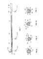
- FIG. 1is a perspective view of a central venous access vena cava filter catheter in accordance with a first embodiment of the present invention with the vena cava filter in an unexpanded state.
- FIG. 2is a side elevational view of a central venous access vena cava filter catheter in accordance with the first embodiment of the present invention.
- FIG. 3is a cross-sectional view taken along line 3 - 3 of FIG. 2 .
- FIG. 4is a cross-sectional view taken along line 4 - 4 of FIG. 2 .
- FIG. 5is a cross-sectional view taken along line 5 - 5 of FIG. 2 .
- FIG. 6is a perspective view of a central venous access vena cava filter catheter in accordance with a second embodiment of the present invention illustrating the vena cava filter in an unexpanded state.
- FIG. 7is a side elevational view of a central venous access vena cava filter catheter in accordance with the second embodiment of the present invention.
- FIG. 8is a cross-sectional view taken along line 8 - 8 of FIG. 7 .
- FIG. 9is a cross-sectional view taken along line 9 - 9 of FIG. 7 .
- FIG. 10is a cross-sectional view taken along line 10 - 10 of FIG. 7 .
- FIG. 11is a cross-sectional view taken along line 11 - 11 of FIG. 7 .
- FIG. 12is a perspective view of the central venous access vena cava filter catheter of FIG. 1 illustrating the vena cava filter in a diametrically expanded state.
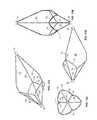
- FIG. 13Ais a perspective view of a vena cava filter member in accordance with a first embodiment thereof.
- FIG. 13Bis a first side elevational view thereof.
- FIG. 13Cis an end elevational view thereof.
- FIG. 13Dis a second side elevational view thereof.
- FIGS. 14A-14Hare perspective views of alternative embodiments of a vena cava filter member in accordance with the present invention.
- FIGS. 15A-15Hare fragmentary side elevational views of the alternative embodiments of the vena cava filter member illustrated in FIGS. 14A-14H .
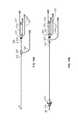
- FIG. 16Ais a side elevational view of the vena cava central line catheter in its undeployed state.
- FIG. 16Bis a side elevational view of the vena cava central line catheter in its deployed state.
- FIG. 17is a side elevational view of a vena cava filter member in its expanded state in accordance with one embodiment of the present invention.
- FIG. 18is a perspective view of a vena cava filter member in its expanded state in accordance with an alternative embodiment of the present invention.
- FIG. 19is a perspective view of a vena cava filter member in its expanded state in accordance with yet another embodiment of the present invention.
- FIG. 20is a perspective view of a vena cava filter member in its expanded state in accordance with still another embodiment of the present invention.
- FIGS. 21A and 21Bare perspective views of a vena cava filter member mounted at a distal end of a central line catheter having a distal balloon.
- FIGS. 22A and 22Bare perspective views of an alternative embodiment of a vena cava filter member mounted at a distal end of a central line catheter having a distal balloon.
- FIG. 23is a side cross sectional view of an embodiment of the vena cava filter member mounted at a distal end of a central line catheter in its expanded state, further comprising an imaging modality disposed within a lumen of the catheter.
- a central venous access filter (“CVAF”) 10that is composed generally of a multi-lumen central venous access catheter body 12 having a proximal port 32 associated with a first lumen 44 and a distal port 34 associated with a second lumen 42 , a filter member 16 , having a first end 18 and a second end 20 , is positioned generally intermediate the distal port 34 and the proximal port 32 and is generally concentric relative to the catheter body 12 .
- An outer sheath 22is concentrically disposed over the catheter body 12 such that relative movement of the catheter body 12 and the outer sheath 22 either exposes the filter member 16 or captures the filter member 16 within the outer sheath 22 .
- the outer sheath 22terminates in an annular opening at a distal end thereof and at first hub member 225 as depicted in FIGS. 16A and 16B .
- the proximal hub 225will be described more fully hereinafter.
- the catheter body 12extends through a central bore in the proximal hub 225 and passes through a central lumen of the outer sheath 22 .
- a second hub member 227is coupled to a proximal end of the catheter body 12 .
- the second hub member 227 and the first hub member 225are removably engageable with each other as will also be described further hereinafter.
- the first end 18 or the second end 20may either be fixed or moveable relative to the catheter body 12 .
- the filter member 16may have only a first end 18 which is fixed to the catheter body 12
- a physicianmay optionally elect to employ an introducer sheath (not shown) as vascular access conduit for the CVAF 10 .
- an introducer sheath(not shown) as vascular access conduit for the CVAF 10 .
- the presence of the filter member 16 at the distal end of the catheter body 12creates a region of relatively lower flexibility and the practitioner may determine it beneficial to employ an introducer sheath for vascular access.
- proximal and distalare intended to refer to positions relative to the longitudinal axis of the catheter body 12 .
- the catheter body 12has a distal end which is first inserted into the patient and a proximal end which opposite the distal end.
- the terms “inferior” or “inferiorly”are intended to refer to the anatomic orientation of being in a direction away from the patient's head while the terms “superior” or “superiorly” are intended to refer to the anatomic orientation of being toward the patient's head.
- the multi-lumen aspect of the inventive central venous access filter catheter 10is shown more clearly in FIGS. 2-5 .
- the catheter body 12has a proximal section 13 and a distal section 14 . which is longitudinally opposite the proximal section 13 , and which may have a relatively smaller diametric profile than the proximal section 13 .
- the first lumen 44terminates at the proximal port 32
- the second lumen 42terminates at the distal port 34 .
- a central guidewire lumen 30may be provided that extends the entire longitudinal length of the catheter body 12 and terminates at the distal end of the catheter body 12 at a distal guidewire opening 31 that permits the catheter body to track along a guidewire during a procedure.
- the central guidewire lumen 30may also be used to introduce fluids, such as bioactive agents, intravenous fluids or blood transfusions.
- At least one of a plurality of infusion lumens 40are provided, each having at least one infusion port 36 that passes through a wall of the catheter body 12 .
- Bioactive agents, flushing fluids for flushing or under elevated pressures for mechanical thrombolysis of thrombus in the filter member 16 , contrast agents or other fluidsmay be infused through the infusion lumens 40 and out of the at least one infusion port 36 to pass into the patient's venous system for either local or systemic effect.
- plural infusion ports 36are provided with multiple ports 36 being provided in communication with a single infusion lumen 40 and spaced along a longitudinal axis of the catheter body 12 .
- plural infusion ports 36may be provided in a circumferentially spaced manner to provide for fluid infusion at points spaced around the circumference of the catheter body 12 .
- fluid infusionis provided along both the longitudinal axis and the circumferential axis of the catheter body 12 within the spatial area defined by and bounded by the filter member 16 .
- the plural infusion ports 36communicate with the spatial area defined by and bounded by filter member 16 , fluids introduced through the infusion lumens 40 are directed immediately at thrombus caught within the filter member 16 . This permits thrombolytic agents, high pressure mechanical thrombolysis using a pressurized saline flush to be introduced directly to the situs of thrombus capture within filter member 16 .
- thermal, ultrasound or other types of thrombolysismay be employed to disrupt thrombus captured by the filter member 16 .
- the annular space between the outer sheath 22 and the catheter body 12may be used to introduce a thrombolytic to the filter and shower the filter to disrupt thrombus caught by the filter member 16 .
- the balloon depicted in FIGS. 21 and 22may be positioned adjacent the filter member 16 and be provided with plural openings oriented in the direction of the filter member 16 to facilitate thrombolysis.
- first lumen 44the second lumen 42 , the guidewire lumen 30 , or the infusion lumens
- the number and arrangement of lumens in the catheter body 12is a function of the desired number of operable ports passing through the walls of the catheter body 12 , the relative position of the operable ports, the desired position and geometry of the guidewire lumen 30 , the desired longitudinal flexibility of the catheter body 12 , the desirable degree of kink resistance of the catheter body 12 , and other factors which are known to one of ordinary skill in the catheter arts.
- an exemplary outer diameter size of the outer sheath 22is between 8 Fr (2.7 mm) and 9 Fr (3.0 mm) while an exemplary outer diameter size of the catheter member 12 is between 6 Fr (2.0 mm) and 7 Fr.
- a diametric transition taper 15may be provided between the proximal portion 13 and the distal portion 14 of the catheter body 12 corresponding to the thickness of the filter member 16 . In this manner, the outer surface of the filter member 16 is substantially co-planar with the outer diameter of the proximal portion 13 of the catheter body 12 about its entire circumference.
- the catheter body member 12may have a constant diameter and the filter member 16 coupled to an outer surface of the catheter body member 12 , with the outer sheath 22 having a luminal diameter sufficient to fit over the filter member 16 .
- the fixed first end 18 of filter 16is positioned adjacent and in abutting relationship with the diametric transition 15
- the moveable second end 20 of filter member 16is concentrically positioned around the distal section 14 of catheter body 12 and is reciprocally moveable thereupon to accommodate diametric expansion of the filter member 16 .
- Lumen diameter and port dimensionare a function of design requirements and are variable depending upon the desired purpose and function of the lumen or port, e.g., pressure sensing, infusion, evacuation, guidewire, flow sensing, or flow conduit.
- At least one radio-opaque or other viewable markermay be provided.
- a first marker 24is provided at the distal end of the outer sheath 22 and a second marker 26 may be provided at a distal tip 33 of the catheter body 12 . It will be understood that when the outer sheath 22 is in its non-retracted delivery position, that the filter 16 will be covered and the marker 24 and the second marker 26 will be adjacent or in close proximity with one another.
- the outer sheath 22may, itself, be made of or include a radio-opaque or other viewable material, such as a metal braid or metal reinforcement within or applied to a polymeric sheath.
- the first and second markers 24 , 26 or the material of the outer sheath 22may enhance visualization of the CVAF 10 under fluoroscopy, ultrasound or other visualization or guidance technique.
- FIGS. 6-11illustrate a second embodiment of the CVAF 50 .
- CVAF 50does not include the central guidewire lumen 30 of CVAF 10 .
- the general construct of CVAF 50is similar to that of CVAF 10 , a different configuration of the inner lumens is employed.
- CVAF 50like CVAF 10 , consists generally of a multi-lumen central venous access catheter body 12 having a proximal port 32 associated with a first lumen 54 and a distal port 34 associated with a second lumen 58 , a filter member 16 , having a fixed first end 18 and a moveable second end 20 , is positioned generally intermediate the distal port 34 and the proximal port 32 and is generally concentric relative to the catheter body 12 .
- Use of the term “generally intermediate”is intended to mean that at least a substantial portion of the filter member 16 resides intermediate the distal port 34 and the proximal port 32 .
- the filter member 16may partially overlay either or both of the proximal port 32 or the distal port 34 .
- the catheter body 12has a proximal section 13 and distal section 14 , which is longitudinally opposite the proximal section 13 which may have a relatively smaller diametric profile than the proximal section 13 .
- the first lumen 54terminates at the proximal port 32
- the second lumen 58terminates at the distal port 34 .
- An atraumatic tip 52terminates the catheter body 12 at its distal end.
- the atraumatic tip 52preferably includes a radio-opaque marker to aid in positional visualization of the distal end of the catheter body 12 .
- a plurality of infusion lumens 56are provided, each having at least one infusion port 36 , preferably plural infusion ports 36 , that passes through a wall of the catheter body 12 and communicates with a space defined within an area bounded by the filter member 16 .
- Bioactive agents, flushing fluids, pressurized mechanical thrombolytic fluids, or other fluidsmay be infused through the infusion lumens 56 and out of the at least one infusion port 36 to pass into the space defined by the filter member 16 and ultimately into the patient's venous system for either local or systemic effect.
- each of the plural infusion lumens 56are in fluid communication with plural ports 36 arrayed along both the longitudinal axis and the circumferential axis of the catheter body.
- This configurationprovides for fluid infusion along both the longitudinal axis and the circumferential axis of the catheter body 12 and in direct communication with the space defined by the filter member 16 that captures thrombus.
- first catheter septum 51is a generally diametrically and longitudinally extending member that divides the first lumen 54 from the second lumen 58 along the longitudinal axis of the catheter body 12 .
- Second catheter septum 56may comprise a generally U-shaped member that intersects the first catheter septum 51 at a lower aspect of the septum and is connected with an inner wall surface of the catheter body 12 at upper aspects of the septum 51 to define two infusion lumens in lateral regions of the catheter body 12 .
- the filter member 16has two general configurations.
- a first configurationconsists generally of two opposing generally open conical sections formed by plural interconnected structural elements defining the lateral surfaces of each open conical section, wherein the two opposing generally open conical sections each have open bases facing each other which are interconnected by a generally cylindrical section of the filter member 16 .
- Each open conical sectionhas an open base and an apex, wherein the apices project in opposing directions, with one apex projecting proximally and another apex projecting distally relative to the axis of the catheter.
- the plural interconnected structural elements forming the lateral surfaces of each generally open conical sectionmay be strut-like structural members extending generally axially along the longitudinal axis of the filter member 16 .
- the axially extending strut-like structural membersmay be linear members or may be curved members.
- the apices of each of the generally open conical sectionsare formed either of a generally cylindrical collar that serves to couple the filter member 16 to the catheter body 12 .
- the generally cylindrical collaris concentrically engaged about the catheter body 12 and may be axially movable thereupon, or is formed by connections between adjacent pairs of longitudinal strut-like structural members which circumscribe a circumference of the catheter body 12 .
- the generally cylindrical section of the filter member 16is formed by a generally open lattice of interconnected structural elements which connect the base of a first open conical section to the base of a second open conical section.
- the generally cylindrical section of the filter member 16lies in apposition with a vascular wall upon deployment of the filter member 16 with a vascular lumen.
- a second general configuration of the filter member 16consists generally of a single generally open conical section in which a plurality of longitudinal strut-like structural members form the lateral surfaces of the conical section and are connected to a generally cylindrical collar which couples the filter member 16 to the catheter body 12 at an apex of the generally open conical section.
- the base of the generally open conical sectionis formed by opposing ends of the longitudinal strut-like structural members.
- a generally cylindrical section of the filter member 16formed of a generally open lattice of interconnected structural elements, extends from the longitudinal strut-like structural members forming the base of the generally open conical section, to provide a region of the filter member 16 which is in apposition to the vascular wall upon deployment of the filter member.
- filter member 16is illustrated in its diametrically expanded configuration in FIGS. 12-13D .
- filter member 16consists generally of a first end 18 and a second end 20 , each of which consists generally of a tubular structure which is circumferentially positioned about a section of the catheter body 12 .
- One of the first end 18 and second end 20are fixedly coupled to the catheter body 12 , while the other is movable relative to the catheter body 12 .
- At least one of a plurality of first strut members 62are coupled at their first end to the first end 18 of filter member 16 and each extends axially relative to the longitudinal axis of the catheter body 12 .
- Each of the first strut members 62is an elongate member that, upon diametric expansion of the filter member 16 , flares away from the central longitudinal axis of the catheter body 12 , in a generally tapered conical manner, and terminates in an end section 63 that bends generally parallel to and along the longitudinal axis of the catheter body 12 .
- a plurality of second strut members 64are coupled at an end to the second end 20 of filter member 16 and each extends parallel relative to the longitudinal axis of the catheter body 12 .
- a plurality of third strut members 66are coupled at ends thereof to an end of the filter member and each extends parallel relative to the longitudinal axis of the catheter body 12 .
- a circumferential member 70extends circumferentially to define a circumferential axis of the filter member 16 and has a series of continuous undulations defining peaks a series of peaks 75 and valleys 77 about the circumference of filter member 16 .
- Each of the plurality of first strut members 62 , the plurality of second strut members 64 and the plurality of third strut members 66are coupled to the circumferential member 70 at different points about its circumferential axis and intermediate the proximal end 18 and the distal end 20 of the filter member 16 .
- the filter member 16In its unexpanded state the filter member 16 has a generally tubular shape, while in its expanded state the filter member 16 assumes one of the general configurations discussed above, i.e., either oppositely extending generally open conical sections or a single generally open conical section.
- the plurality of first strut members 62are preferably offset from each other by approximately 120 degrees about the circumference of the catheter body 12 .
- the plurality of second strut members 64are also preferably offset from each other by approximately 120 degrees.
- the plurality of third strut members 66are also preferably offset from each other by approximately 120 degrees.
- Each of the plurality of first strut members 62couple at a junction 76 to the circumferential member 70 at a peak thereof.
- each of the plurality of third strut members 66couple at junction 76 to the circumferential member 70 at a peak thereof.
- a first strut member 62 and a third strut member 66are each coupled to circumferential member 70 at junction 76 and, in this relationship, form a generally linear member that extends along the longitudinal axis of the catheter body and connects between the proximal end 18 of the filter member 16 and the distal end 20 of the filter member 16 .
- Each of the second strut members 64couple, at their proximal ends to a valley 77 of the circumferential member 70 and connects at a junction 79 .
- the circumferential member 70assumes a generally circumferential tri-leaflet ring having three peaks 75 and three valleys 77 which circumferentially circumscribe a central opening 72 which faces inferiorly relative to the patient's blood flow such that the blood flow first passes into the central opening 72 and past the third strut members 66 and the second strut members 64 then past the first strut members 62 .
- each of the plurality of first strut members 62 , plurality of second strut members 64 , plurality of third strut members 66 and the circumferential member 70are preferably fabricated of biocompatible materials, such as shape memory alloys, superelastic materials or elastic materials, including, without limitation, titanium, vanadium, aluminum, nickel, tantalum, zirconium, chromium, silver, gold, silicon, magnesium, niobium, scandium, platinum, cobalt, palladium, manganese, molybdenum and alloys thereof, such as zirconium-titanium-tantalum alloys, cobalt-chromium-molybdenum alloys, nitinol, and stainless steel.
- biocompatible materialssuch as shape memory alloys, superelastic materials or elastic materials, including, without limitation, titanium, vanadium, aluminum, nickel, tantalum, zirconium, chromium, silver, gold, silicon, magnesium, niobium, scandium, platinum, co
- FIGS. 14A-14H and corresponding FIGS. 15A-15Hdepict alternative embodiments of the filter member 16 , labeled 80 , 90 , 100 , 110 , 120 , 130 , 140 and 150 , respectively.
- each of filter members 80 , 90 , 100 , 110 , 120 , 130 , 140 and 150having a first end 18 and a second end 20 that each consist of a generally ring-like structure intended to circumferentially couple to a catheter body 12 (not shown), with the first end 18 being fixed and the second end 20 being reciprocally moveable axially along the distal portion 14 of catheter body 12 .
- 14A-14H and 15 A- 15 Hconsist of a plurality of first strut members 81 , 91 , 101 , 111 , 121 , 131 , 141 and 151 , respectively, extending distally from the first end 18 of the filter member and a plurality of second strut members 83 , 93 , 103 , 113 , 123 , 133 , 143 and 153 , respectively, extending proximally from the distal end 20 of the filter member, with a diametrically expansible circumferential member 87 , 97 , 107 , 117 , 127 , 137 , 147 , 157 , respectively, interconnecting the distally extending strut members 81 , 91 , 101 , 111 , 121 , 131 , 141 and 151 , respectively, with the proximally extending strut members 83 , 93 , 103 , 113 , 123 , respectively
- At least some distally extending strut members and at least some of the proximally extending strut membersform linear elements that extend along the entire longitudinal axis of the respective filter member, with the circumferential member being comprised of at least one undulating or serpentine ring structure.
- a plurality of distally extending strut membersare provided spaced approximately 120 degrees apart from one and other about the circumference of the filter members, and the distally extending strut members bifurcating once or twice distally in a generally Y-shaped manner as in filter members 80 , 130 , 140 or 150 , or the proximally extending strut members bifurcating proximally in a generally Y-shaped manner and interconnecting with the distally extending generally Y-shaped strut members to form a diamond-like pattern as in filter member 90 .
- the circumferential memberis formed by the diamond-like pattern formed by the intersection of the plurality of struts.
- the circumferential memberis formed by at least one undulating or serpentine ring structure which is diametrically expansible.
- each undulating or serpentine ring structureis interconnected by an interconnecting member 114 , 124 , 134 , respectively, either with an adjacent ring structure, as in filter member 110 or to a distal end 20 of the filter member itself
- a longitudinally serpentine section 132 in filter 32may be provided in conjunction with the interconnecting member 134 , to afford greater expansive properties to the circumferential member 137 .
- the filter member 16is characterized by a generally conical filter member 16 having a greater open surface area exposed to the flow of embolic material into the filter at its proximal end, while the distal end has smaller open surface area exposed to the flow of embolic material to capture the embolic material in the distal end of the filter member.
- the filter member 16is characterized by a generally conical filter member 16 having a greater open surface area exposed to the flow of embolic material into the filter at its distal end, which the proximal end of the filter member 16 has a smaller open surface area exposed to the flow to capture smaller embolic material in the distal end of the filter member 16 .
- the filter member 16is self-centering to provide proper apposition against the vascular walls and centering within the lumen of a blood vessel. This maximizes the flow dynamics of the filter member 16 within the blood vessel for purposes of capturing embolic material within the struts of the filter and centers the catheter body member 12 within the vascular lumen.
- proximal 32 and distal 34 portsserve as means for measuring flow rates or pressure differentials across the filter 16 .
- Thismay be accomplished by including flow sensors and/or pressure transducers 19 in operable association with each port 32 , 34 , with the associated electrical connections to the flow sensors an/or pressure transducers 19 passing through the respective lumens associated with each port 32 , 34 and terminating at the proximal end of the catheter body 12 .
- flow sensors 19are employed, a single flow sensor associated with proximal port 32 , the distal port 34 or the distal end of outer sheath 22 may be sufficient to detect fluid flow rate at the position of the catheter body 12 .
- the clinicianwill be able to determine flow velocity at the distal end of the outer sheath 22 prior to introducing the catheter body 12 and make fine adjustments to the placement of the distal end of the outer sheath 22 to ensure proper placement for the filter member 16 .
- Plural flow sensors 19may be employed and operably associated with each of proximal port 32 and distal port 34 to sense changes in flow velocity across the filter member 16 .
- the flow sensors and/or pressure transducers 19may reside in communication with the lumens respectively associated with each port 32 , 34 at the proximal end of the catheter body 12 , thereby eliminating the need for electrical connectors resident with the associated lumens.
- wireless flow sensors and/or pressure transducersmay be provided in communication with each port 32 , 34 , and be operably coupled to a power source and a transmitter to wirelessly transmit telemetry data from the transducers to a wireless receiver in communication with the transmitter, as is known in the art.
- the proximal 32 and distal ports 34may be used for monitoring or sensing other conditions in the body that are detectable in the blood.
- analyte sensorsmay be introduced to either the lumens communicating with the proximal 32 or distal ports 34 or to the ports themselves to monitor and/or sense chemical or biochemical conditions in the body.
- An example of this applicationis monitoring or sampling blood glucose levels for diabetes control.
- the proximal 32 and distal ports 34may be used for fluid infusion or for withdrawal or evacuation of fluids or other material through the catheter body 12 .
- thrombus collected in the filter member 16may capable of being lysed, either by thrombolysis through the infusion ports 36 or under the influence of thermal or mechanical lysis, such as by introducing a laser, ultrasound or other system capable of lysing thrombus, which may be introduced through the lumen communicating with the proximal port 32 , or the distal port 34 or the guidewire lumen 30 , or introduced separately from the CVAF 10 , positioned within the space bounded by the filter member 16 , lysing thrombus collected in the filter member 16 and evacuating the lysed thrombus through the proximal port 32
- flow rateincreases proximally within the venous system. For example a flow rate of 1 L/min is typical in one femoral vein, increases to 2 L/min in the inferior vena cava and increasing another 0.7 to 1 L/min proximate the renal veins. Knowing the typical flow velocities in vessels of different transverse cross-sectional areas, coupled with a flow sensor 19 associated with the multi-lumen catheter body 12 may serve to supplement or replace the requirements for fluoroscopy or sonography in placement of the CVAF 10 , 50 .
- sensorssuch as, for example, chemosensors, color sensors, electrical sensors or biosensors, may be employed in lieu of or in addition to pressure transducer and/or a flow sensor 19 in order to detect other changes or conditions within the patient's vasculature.
- color sensorsexist that sense color changes in thrombus, such color changes may be displayed and interpreted by the medical practitioner as an indication of thrombus staging.
- Analyte sensorssuch a as a glucose sensor or an oxygen saturation sensor may also be employed.
- the filter member 16may be fixed to the catheter body 12 or may be removably coupled to the catheter body 12 for deployment as either a permanent filter or as a temporary and retrievable vena cava filter. Removable coupling of the filter member to the catheter body 12 may be accomplished with a variety of release and retrieval mechanisms operably associated the catheter body 12 and proximate the diametric transition 15 .
- Non-limiting examples of such release and retrieval mechanismsinclude a wire release that engages with a the first end 18 of the filter, a cooperating indexed detent and projection interaction between the catheter body 12 and the first end 18 of the filter, such as a detent in the proximal end of the filter and a cooperating projection in the multi-lumen catheter that is positionally indexed to the detent and releasable from the detent, or, alternatively, a helical slot or threads may be formed in the proximal end 18 of the filter and indexed and cooperating projection in the multi-lumen catheter than permits engagement and disengagement with the helical slot or threads.
- an introducer sheathis first placed into the body in a normal manner for introducing a central venous line, such as by the Seldinger technique. Specifically, after accessing a vein using a large bore needle, under local anesthesia, a guidewire is inserted through the needle bore and passed into the vein. Once the guidewire is positioned, the needle is withdrawn, and a dilator together with the introducer sheath introduced over the guidewire. Once the introducer sheath is positioned at a desired location within the venous system under radiography, the dilator may be removed from the patient. Radiopaque markers associated with the introducer sheath may be employed to assist in positional visualization of the distal end of the introducer sheath.
- the outer sheath 22 covering the filter 16is removed while introducing the filter member 16 and catheter body 12 into the introducer sheath.
- the outer sheath 22constrains the filter member 16 during its passage through the introducer sheath and positioning the distal end of the catheter within the patient's vasculature. Once the distal end of the catheter body 12 reaches the distal end of the introducer sheath, the filter is deployed. If the filter therapy alone is desired, the filter member 16 is detached from the catheter body 12 and the catheter body 12 , introducer sheath and guidewire is withdrawn from the patient. Where both central venous access and filter therapy is desired, the introducer sheath and catheter body 12 with the filter member 16 is left in the patient until withdrawal is required.
- Retrieval and removal of a detached filter member 16is accomplished using a second procedure under local anesthesia which substantially replicates the placement of the CVAF, with a capture sheath (not shown), similar to introducer sheath, being introduced, a retrieval catheter being introduced through the sheath, and engaging the filter member 16 , then withdrawn into the capture sheath to collapse the filter member 16 , with the entire assembly of the filter member 16 , catheter body 12 , outer sheath 22 and guidewire, if used, is withdrawn from the patient.
- FIGS. 16A and 16Bwhich depict the undeployed state ( FIG. 16A ) and the deployed state ( FIG. 16B ) of the filter member 216 , respectively, common to each of the embodiments of the present invention 200 is an inner catheter 214 that carries the vena cava filter 216 at a distal end thereof.
- the inner catheter 214is concentrically and reciprocally engaged within an outer sheath 222 such that relative axial movement of the inner catheter 214 and the outer sheath 222 either exposes the vena cava filter 216 for deployment or captures the vena cava filter 216 for retrieval.
- a first hub member 225is coupled to a proximal end of the outer sheath 222 and a second hub member 227 is coupled to a proximal end of the inner catheter 214 .
- First hub member 225 and second hub member 227are engageable, such as by a threaded, bayonet, snap fit, friction fit or interference fit fitting, to secure the inner catheter 214 within the outer sheath 222 and restrict relative axial movement of the two elements after deployment of the vena cava filter 216 .
- a flush line 229communicates with the first hub member 225 and is in fluid communication with a luminal space within the outer sheath 222 .
- a plurality of fluid lines 231 , 233 , 235 , 237communicate with the second hub member 227 and are each in fluid communication with one of the plural lumens within the inner catheter member 214 , e.g., lumens communicating with the proximal, distal or infusion ports (not shown).
- a distal tip 26is provided at a distal end of the inner catheter.
- a jugular approachnecessitates that the catheter be introduced retrograde relative to the vector of blood flow within the vena cava, i.e., the catheter is introduced through the jugular vein and directed inferiorly toward an infrarenal position. Additionally, since the blood flow opposes the distal end of the catheter and passes toward the proximal end, the vena cava filter must open inferiorly such that its largest diametric section in apposition to the vessel walls opens toward the distal end of the catheter rather than toward the proximal end of the catheter as with the femoral approach.
- FIGS. 17-20depict alternative embodiments of vena cava filter members in accordance with the present invention.
- FIG. 17illustrates a filter orientation for a femoral approach
- FIGS. 18-20illustrate a filter orientation for a jugular approach.
- filter member 216defines a relatively larger volume open space 201 and a relatively smaller volume open space 203 .
- Open spaces 201 and 203are bounded by structural members of the filter member 216 and are both open toward the direction of blood flow indicated by arrow 5 , with larger open space 201 being relatively upstream the blood flow relative to smaller open space 203 in both the femoral or the jugular orientation of filter member 216 .
- filter member 216is formed of plural interconnected structural elements.
- the filter memberhas a first end 218 and a second end 220 , at least one of which is attached to the distal section 214 of the catheter body 212 .
- First structural members 217extend generally axially, either proximally as shown in FIG. 17 or distally as shown in FIG. 18 , along the longitudinal axis of the filter member 216 .
- first structural members 217are connected to either the first end 218 or the second end 220 of the filter member 216 .
- Second structural members 219are connected to the first structural members 217 at an end of the first structural members 217 which is opposite that connected to either the first end 218 or the second end 220 of the filter member 216 .
- the second structural members 219form at least two successive zigzag shaped structures which are connected to an end of the first structural members and at opposing apices 223 to form conjoined ring-like structures about the circumference of the filter member 216 .
- the second structural members 219generally define lattice-like pattern upon diametric expansion of the filter member 216 .
- the lattice-like pattern formed by the second structural members 219projects axially along the longitudinal axis of the catheter 214 tapering to form at least one petal-like projection 225 that terminates in a terminal apex member 227 .
- FIG. 17depicts three petal like projections 225 , with one being behind the plane of the figure and, therefore, not shown.
- Each of the petal-like projections 225act to engage and oppose vascular wall surfaces to seat the filter member 216 against the vessel wall, and center the filter member and catheter 214 within the vascular lumen.
- third structural members 221are provided and are connected to each of the terminal apex members 227 and extend axially relative to the catheter 214 and connect with a second end 218 of the filter member 216 .
- the first end 218 of the filter member 216is fixedly connected to the catheter 212
- the second end 220 of the filter member 216is movably coupled to the catheter 212 and moves axially along the catheter 216 upon expansion or contraction of the filter member 216 .
- FIG. 18depicts an embodiment of the filter member 216 identical to that illustrated in FIG. 19 , with the sole exception that the third structural members 219 and the second end 220 of the filter member 216 are omitted.
- the terminal apex member 227 of each petal-like member 225are not connected to a second end 220 of the filter member 216 by the third structural members 219 .
- FIG. 20depicts an alternative embodiment of the filter member 216 which is similar to that depicted in FIG. 18 , except that at least one circumferential ring member 252 is connected to the terminal apex member 227 of each of the petal-like members 225 at a juncture 253 with the terminal apex member 227 .
- the addition of the additional circumferential ring member 252results in a relative elongation over the length L 1 of the filter member 216 depicted in FIG. 18 by a length L 2 which facilitates additional apposition between the filter member 216 and the vascular wall and stabilization of the petal-like members 225 .
- FIGS. 21A and 21Bdepict an alternative embodiment of the filter member 216 in FIG. 18 , having first end 318 , first structural elements 317 and second structural elements 319 all analogously arranged as in the embodiment of FIG. 18 .
- Filter member 300employs a modified distal end 314 of the catheter 312 to include an expansive balloon 360 .
- the guidewire lumen of the multi-lumen catheter 312may be used in place of a distal port for condition sensing, flushing, infusion or the like.
- the expansive balloon 360may be used to break up thrombus captured within the filter member 316 , either by mechanical force through serial dilatation or by infusion of a thrombolytic agent through openings in the balloon 360 .
- FIG. 21Adepicts the balloon 360 in its collapsed state
- FIG. 21Bdepicts the balloon in its expanded state.
- an expansive balloon 360may be placed proximal the filter member 300 and serve to temporarily occlude the vessel to facilitate aspiration or evacuation of thrombus from the filter member 30 .
- FIGS. 22A and 22Bdepict an alternative embodiment of the filter member 216 in FIG. 20 having first end 418 , first structural elements 417 and second structural elements 419 , at least one circumferential ring member 452 connected to the terminal apex member 427 of each of the petal-like members 425 at a juncture 453 with the terminal apex member 427 ; all analogously arranged as in the embodiment of FIG. 20 .
- Filter member 400employs a modified distal end 414 of the catheter 412 to include an expansive balloon 460 .
- the guidewire lumen of the multi-lumen catheter 412may be used in place of a distal port for condition sensing, flushing, infusion or the like.
- the expansive balloon 460may be used to break up thrombus captured within the filter member 416 , either by mechanical force through serial dilatation or by infusion of a thrombolytic agent through openings in the balloon 460 .
- FIG. 22Adepicts the balloon 460 in its collapsed state
- FIG. 22Bdepicts the balloon in its expanded state.
- an expansive balloon 460may be positioned proximal the filter member 416 to permit temporary occlusion of the blood vessel and permit aspiration or evacuation of thrombus from the filter member 416 .
- Each of the foregoing embodiments of the present inventionmay further be adapted for use with an imaging modality to facilitate intravascular imaging of the filter member from beyond or within a lumen of the multi-lumen catheter.
- the imaging modalitymay pass entirely through the distal tip of the multi-lumen catheter, and enable an operator to use the intravascular imaging modality to visualize the origins of the renal veins. This could allow the operator to place the catheter without use of external imaging (i.e. fluoroscopy, trans-abdominal duplex ultrasound, CT, etc.).
- intravascular imaging systemsutilize a sheath through which a signal is transmitted and received.
- the multi-lumen catheter with associated filter membermay serve as the sheath for introduction of an intravascular imaging system, permitting improved imaging of the condition of the filter member while in use.
- the use of an intravascular imaging system with the multi-lumen catheter with associated filter memberwill permit a medical professional to monitor the condition of the filter member, and utilize appropriate techniques to lyse a collected thrombus.
- the lysing techniquesmay be more specifically and accurately targeted, as compared to lysing techniques applied without the benefit of imaging the condition of the filter member.
- the intravascular imaging systemmay also enable a medical professional to visualize the filter catheter for placement within a patient.
- FIG. 23depicts a cross-sectional side view of one embodiment of the expanded filter member and catheter assembly of FIG. 12 , further comprising an imaging modality.
- filter member 516consists generally of a first end 518 and a second end 520 , each of which consists generally of a tubular structure which is circumferentially positioned about a section of the catheter body 512 .
- One of the first end 518 and second end 520are fixedly coupled to the catheter body 512 , while the other is movable relative to the catheter body 512 .
- the filter memberis structurally analogous to that discussed above, such as in relation to FIG. 12 above.
- the filter member 516In its unexpanded state the filter member 516 has a generally tubular shape, while in its expanded state the filter member 516 assumes one of the general configurations discussed above, i.e., either oppositely extending generally open conical sections or a single generally open conical section.
- the assemblymay further comprise an outer sheath 522 disposed over the catheter body 512 .
- the catheter body 512includes a distal portion 514 about which the filter member 516 is disposed.
- Catheter body 512further includes at least one lumen 530 , such as a central guidewire lumen, which may extend the entire longitudinal length of the catheter body 512 and may terminate at the distal end of the catheter body 512 at a distal opening 531 .
- the central lumen 530may be used to house and/or introduce elements of an imaging system.
- the lumen into which the imaging system is disposedis not the central lumen, but another lumen of the multi-lumen catheter body 512 , so long as the imaging system is able to image the filter member 516 .
- imaging systemsinclude intravascular ultrasound (IVUS), optical coherence tomography (OCT), side looking OCT, ultrasound, thermography, IR imaging, Florence imaging, luminescent imaging, MRI, videography, photoacoustic, and other similar imaging technologies. These systems may permit 360 degree imaging, or be side looking and rotatable to image through 360 degrees.
- the systemgenerally includes an imaging core drive cable 630 and an imaging probe 650 .
- the imaging probe 650may be a tip, cone, and/or the like disposed at a distal end of the imaging core drive cable 630 , wherein the imaging probe 650 and/or the drive cable 630 are operably connected to an external system (not shown) for operating the imaging system.
- the imaging probe 650may be disposed within a portion 600 of the central lumen 530 bounded by a proximal end 518 and a distal end 520 of the filter member 516 .
- the imaging probe 650may be operated to help a user detect the presence of a thrombus captured by the filter member 516 .
- the imaging probe 650may also help detect the size and/or position of a captured thrombus.
- the imaging probe 650may be rotated and/or translated within the lumen 530 , so as to permit imaging of the entire filter member 516 .
- the imaging probe 650may be adapted to permit 360 degree imaging of the filter member 516 without requiring rotation.
- the imaging probe 650may be adapted to permit imaging of the length of the filter member 516 without distal or proximal translation.
- the imaging probe 650is operable to image the filter member 516 in an expanded state.
- the imaging probe 650may transmit and receive an imaging signal through a wall of the lumen 530 .
- the imaging signalmay depend upon the particular imaging system utilized, and generally comprises a transmitted signal, wave, energy, or the like that is emitted from the imaging probe 650 in order to image or visualize the filter member 516 .
- the relevant portion of the lumen 530is a section 600 of the distal portion 514 of the catheter body 512 bounded by the proximal end 518 and distal end 520 of the filter member 516 .
- the dimensions and/or material of any or all of either the bounded portion 600 or the distal portion 514may be selected to maximize imaging signal transmission and/or imaging signal clarity. Examples of appropriate materials include, but are not limited to, polyethylene, PTFE, and other polymers.
- the filter 516may be attached to a distal end of a single or a multi-lumen catheter 512 .
- the region bounded by the proximal and distal ends of the filter 516is open and free of imaging obstruction.
- the imaging modalitymay be disposed through the lumen of the catheter 512 and translated such that it extends beyond the distal end of the lumen and into the open region between the proximal and distal ends of the filter 516 .
- the imaging systemis an IVUS system
- the portion of the catheter body 512 from which the imaging probe 650 imagesis acoustically transparent to allow for the transmission of the imaging signal, ultrasound waves for IVUS, through the body 512 .
- the imaging probe 650may comprise an ultrasound transducer connected to the distal end of a drive cable 630 , which extends through the lumen 530 of the catheter body 512 .
- the drive cable 630is used to rotate and translate the transducer of the imaging probe 650 within the catheter lumen 530 .
- the drive cable 630may possess a high torsional stiffness so that the drive cable 630 can transmit torque from a drive motor (not shown) to the transducer to rotate the transducer.
- rotation of the transduceris not necessary, such as when the imaging probe 650 is capable of 360 degree imaging.
- the drive cable 630may also possess a low bending stiffness allowing the drive to bend along a tortuous path of a blood vessel.
- the imaging probe 650is operably connected to ultrasound electronics (not shown) external a patient. In one embodiment, the operable connection may be via a wire that runs along the drive cable 630 .
- intravascular OCTuses a high-bandwidth light source instead of an ultrasound-emitting crystal to create high-resolution images.
- OCTis an interferometric technique, typically employing near-infrared light, where an optical beam is directed at tissue, and a small portion of this light that reflects from sub-surface features is collected.
- the imaging systemis an OCT system, preferably the portion of the catheter body 512 from within which the imaging probe 650 images is optically transparent to allow for the transmission of the imaging signal, light waves for OCT, through the portion of the catheter body 512 .
- the imaging probe 650may comprise an optical emitter connected to the distal end of a drive cable 630 , which extends through the lumen 530 of the catheter body 512 .
- the drive cable 630is used to rotate and/or translate the optical emitter of the imaging probe 650 within the catheter lumen 530 .
- the imaging probe 650is operably connected to OCT electronics (not shown) external a patient.
- the operable connectionmay be via a wire that runs along the drive cable 630 .
- the operable connectionmay be via an optical waveguide that runs along the drive cable 630 .
- imaging modalitymay generally be incorporated into any of the above disclosed embodiments of the multi-lumen catheter and filter member assembly.
- an imaging catheterhousing an imaging probe therein, may be disposed within a lumen of the IVC filter catheter.
- the imaging catheteris not coupled to the IVC filter catheter, and may be disposed within an appropriately sized lumen of the IVC filter catheter.
- the imaging modalitymay thus be positioned within or beyond a lumen of the IVC filter catheter, as a self contained system.
- an imaging catheterhousing an imaging core therein, is integral with a lumen of the IVC filter catheter.
- the imaging coremay be translated proximally and/or distally relative to the imaging catheter and/or the IVC filter catheter.
- a medial filter portmay be used as a conduit to deliver an imaging catheter to the caval space within the filter.
- the imaging cathetermay be coupled to the proximal hub of the catheter, by any one of the proximal hubs as disclosed U.S. provisional patent application Ser. No. 61/584,716, filed Jan. 9, 2011, U.S. patent application Ser. No. 13/083,053, filed Apr. 8, 2011, which are hereby incorporated by reference in their entirety.
- the imaging probe 650may be disposed within a lumen of a multi-lumen catheter sheath, such as that disclosed in commonly owned and U.S. provisional patent application Ser. No. 61/668,308, filed Jul. 5, 2012, which is hereby incorporated by reference in its entirety.
- the imaging probe 650may be disposed in the lumen of the multi-lumen sheath rather than the filter catheter.
- the imaging probe 650may be translated so as to be disposed within a region bounded by the proximal end 518 and distal end 520 of the filter member 516 .
- the structure and operation of this embodimentis analogous to those disclosed above.
- the imaging systemmay be used with the filter member to monitor the condition of the filter member and to capture a thrombus within a blood vessel. This may be accomplished by introducing the multi-lumen catheter, having the filter member coupled thereto, into the blood vessel. The catheter may then be deployed within the blood vessel such that the filter has an enlarged diametric opening facing a patient's blood flow. The imaging system may then be translated through a lumen of the multi-lumen catheter and be operable to image or visualize the condition of the filter member. If a thrombus is detected, then a fluid may be infused through at least one lumen in the multi-lumen catheter in communication with at least one infusion port passing through the multi-lumen catheter and open to an inner spatial area bounded by the filter member. Alternatively, other means of lysing a detected thrombus may be utilized, such as thermal or mechanical lysis, such as by introducing a laser, ultrasound, or other system capable of lysing thrombus.
- the imaging systemmay be used with a multi-lumen sheath coupled to a filter catheter, such that the imaging system is disposed within a lumen of the multi-lumen sheath and images the filter member.
- the filter memberhas a relatively larger opening that is open inferiorly in a direction that opposes the blood flow vector and employs structural elements that taper superiorly along the direction of the blood flow vector to reduce the open surface area of the filter member and capture thrombus.
- a central venous access filterin accordance with the foregoing embodiments of the invention which include, generally, a multi-lumen catheter body, a filter member and an introducer sheath.
- the multi-lumen catheter bodyhas a plurality of ports each of which are in fluid flow communication with at least one lumen in the multi-lumen catheter body.
- Lumensmay include a central guidewire lumen useful for tracking over a guidewire and/or larger volume infusion of bioactive agents, intravenous fluids, blood transfusions, or other fluids; infusion lumens in communication with infusion ports positioned to direct fluids to the space bounded by the filter member for introducing bioactive agents, including thrombolytic agents or flushing agents, including pressurized fluids for mechanical thrombolysis directly to the capture site of the thrombus in the filter member; and lumens communicating with proximal and distal ports which may also be used for fluid introduction and/or may house or communicate with sensors, such as pressure transducers, flow sensors, analyte sensors, color sensors, optical sensors or the like.
- sensorssuch as pressure transducers, flow sensors, analyte sensors, color sensors, optical sensors or the like.
- the filter membermay be detachable from the multi-lumen catheter body to permit temporary filter placement and later retrieval by a detachment mechanism that cooperates between the filter and the multi-lumen catheter body.
Landscapes
- Health & Medical Sciences (AREA)
- Life Sciences & Earth Sciences (AREA)
- General Health & Medical Sciences (AREA)
- Animal Behavior & Ethology (AREA)
- Veterinary Medicine (AREA)
- Engineering & Computer Science (AREA)
- Biomedical Technology (AREA)
- Heart & Thoracic Surgery (AREA)
- Public Health (AREA)
- Surgery (AREA)
- Biophysics (AREA)
- Medical Informatics (AREA)
- Molecular Biology (AREA)
- Physics & Mathematics (AREA)
- Pathology (AREA)
- Nuclear Medicine, Radiotherapy & Molecular Imaging (AREA)
- Radiology & Medical Imaging (AREA)
- Vascular Medicine (AREA)
- Cardiology (AREA)
- Transplantation (AREA)
- Oral & Maxillofacial Surgery (AREA)
- Physiology (AREA)
- Optics & Photonics (AREA)
- Hematology (AREA)
- Anesthesiology (AREA)
- Pulmonology (AREA)
- Surgical Instruments (AREA)
Abstract
Description
Claims (6)
Priority Applications (5)
| Application Number | Priority Date | Filing Date | Title |
|---|---|---|---|
| US13/735,810US9039728B2 (en) | 2007-08-31 | 2013-01-07 | IVC filter catheter with imaging modality |
| US13/918,601US9039729B2 (en) | 2007-08-31 | 2013-06-14 | IVC filter catheter with imaging modality |
| PCT/US2014/010505WO2014107727A1 (en) | 2013-01-07 | 2014-01-07 | Ivc filter catheter with imaging modality |
| EP14735122.5AEP2941295A4 (en) | 2013-01-07 | 2014-01-07 | Ivc filter catheter with imaging modality |
| US14/721,931US20150327978A1 (en) | 2007-08-31 | 2015-05-26 | Imaging ivc filter catheter and method |
Applications Claiming Priority (4)
| Application Number | Priority Date | Filing Date | Title |
|---|---|---|---|
| US11/849,225US8668712B2 (en) | 2007-08-31 | 2007-08-31 | Multi-lumen central access vena cava filter apparatus and method of using same |
| US12/684,839US8613753B2 (en) | 2007-08-31 | 2010-01-08 | Multi-lumen central access vena cava filter apparatus and method of using same |
| US201261668308P | 2012-07-05 | 2012-07-05 | |
| US13/735,810US9039728B2 (en) | 2007-08-31 | 2013-01-07 | IVC filter catheter with imaging modality |
Related Parent Applications (1)
| Application Number | Title | Priority Date | Filing Date |
|---|---|---|---|
| US12/684,839Continuation-In-PartUS8613753B2 (en) | 2007-08-31 | 2010-01-08 | Multi-lumen central access vena cava filter apparatus and method of using same |
Related Child Applications (1)
| Application Number | Title | Priority Date | Filing Date |
|---|---|---|---|
| US13/918,601ContinuationUS9039729B2 (en) | 2007-08-31 | 2013-06-14 | IVC filter catheter with imaging modality |
Publications (2)
| Publication Number | Publication Date |
|---|---|
| US20130190803A1 US20130190803A1 (en) | 2013-07-25 |
| US9039728B2true US9039728B2 (en) | 2015-05-26 |
Family
ID=48797827
Family Applications (3)
| Application Number | Title | Priority Date | Filing Date |
|---|---|---|---|
| US13/735,810Active2028-02-15US9039728B2 (en) | 2007-08-31 | 2013-01-07 | IVC filter catheter with imaging modality |
| US13/918,601Active2027-09-19US9039729B2 (en) | 2007-08-31 | 2013-06-14 | IVC filter catheter with imaging modality |
| US14/721,931AbandonedUS20150327978A1 (en) | 2007-08-31 | 2015-05-26 | Imaging ivc filter catheter and method |
Family Applications After (2)
| Application Number | Title | Priority Date | Filing Date |
|---|---|---|---|
| US13/918,601Active2027-09-19US9039729B2 (en) | 2007-08-31 | 2013-06-14 | IVC filter catheter with imaging modality |
| US14/721,931AbandonedUS20150327978A1 (en) | 2007-08-31 | 2015-05-26 | Imaging ivc filter catheter and method |
Country Status (1)
| Country | Link |
|---|---|
| US (3) | US9039728B2 (en) |
Cited By (1)
| Publication number | Priority date | Publication date | Assignee | Title |
|---|---|---|---|---|
| US10737076B2 (en) | 2016-12-21 | 2020-08-11 | Integra LifeSciences Switzerland Sárl | Self-offsetting implantable catheter system |
Families Citing this family (28)
| Publication number | Priority date | Publication date | Assignee | Title |
|---|---|---|---|---|
| JP5998147B2 (en)* | 2011-09-27 | 2016-09-28 | 寛治 井上 | Vascular free substance capture device |
| WO2013081905A1 (en)* | 2011-11-28 | 2013-06-06 | St. Jude Medical Puerto Rico Llc | Anchor device for large bore vascular closure |
| US9427300B2 (en) | 2012-04-30 | 2016-08-30 | BiO2 Medical, Inc. | Multi-lumen central access vena cava filter apparatus for clot management and method of using same |
| US11406498B2 (en) | 2012-12-20 | 2022-08-09 | Philips Image Guided Therapy Corporation | Implant delivery system and implants |
| CN105611903B (en)* | 2013-08-30 | 2017-11-21 | 雪松-西奈医学中心 | For taking out the apparatus and method of mechanical heart valve leaflets through conduit |
| CN105813553B (en)* | 2013-12-06 | 2021-03-26 | 火山公司 | Devices, systems and methods for assessing intravascular pressure |
| US11006840B2 (en) | 2013-12-06 | 2021-05-18 | Philips Image Guided Therapy Corporation | Device, system, and method for assessing intravascular pressure |
| JP6636450B2 (en)* | 2014-04-11 | 2020-01-29 | コーニンクレッカ フィリップス エヌ ヴェKoninklijke Philips N.V. | Implant delivery system and implant |
| WO2016158073A1 (en)* | 2015-03-31 | 2016-10-06 | 富士フイルム株式会社 | Biopsy needle and photoacoustic measurement device |
| JP2019507193A (en) | 2016-03-04 | 2019-03-14 | ジェームズ・エム・ライナーソン | Method for treating ocular disorders by inhibiting or interfering with bacterial biofilm formation |
| US11819229B2 (en) | 2019-06-19 | 2023-11-21 | Boston Scientific Scimed, Inc. | Balloon surface photoacoustic pressure wave generation to disrupt vascular lesions |
| CN109045445A (en)* | 2018-09-19 | 2018-12-21 | 河南豫乾技术转移中心有限公司 | Uterus cleaning plant for gynemetrics |
| US12402946B2 (en) | 2019-06-19 | 2025-09-02 | Boston Scientific Scimed, Inc. | Breakdown of laser pulse energy for breakup of vascular calcium |
| US11717139B2 (en) | 2019-06-19 | 2023-08-08 | Bolt Medical, Inc. | Plasma creation via nonaqueous optical breakdown of laser pulse energy for breakup of vascular calcium |
| US12280223B2 (en) | 2019-06-26 | 2025-04-22 | Boston Scientific Scimed, Inc. | Focusing element for plasma system to disrupt vascular lesions |
| US20210001091A1 (en)* | 2019-07-01 | 2021-01-07 | Gerald Ernst Schmidt | Remote access vascular and soft tissue tunneling dilator systems and methods of use |
| US20210052361A1 (en)* | 2019-08-22 | 2021-02-25 | Koninklijke Philips N.V. | System for sensing the filling of an embolic protection device by pressure monitoring |
| US12102384B2 (en) | 2019-11-13 | 2024-10-01 | Bolt Medical, Inc. | Dynamic intravascular lithotripsy device with movable energy guide |
| US12274497B2 (en) | 2019-12-18 | 2025-04-15 | Bolt Medical, Inc. | Multiplexer for laser-driven intravascular lithotripsy device |
| US20210267685A1 (en)* | 2020-02-27 | 2021-09-02 | Bolt Medical, Inc. | Fluid recirculation system for intravascular lithotripsy device |
| US20210290286A1 (en) | 2020-03-18 | 2021-09-23 | Bolt Medical, Inc. | Optical analyzer assembly and method for intravascular lithotripsy device |
| US12295654B2 (en) | 2020-06-03 | 2025-05-13 | Boston Scientific Scimed, Inc. | System and method for maintaining balloon integrity within intravascular lithotripsy device with plasma generator |
| US12207870B2 (en) | 2020-06-15 | 2025-01-28 | Boston Scientific Scimed, Inc. | Spectroscopic tissue identification for balloon intravascular lithotripsy guidance |
| US12016610B2 (en) | 2020-12-11 | 2024-06-25 | Bolt Medical, Inc. | Catheter system for valvuloplasty procedure |
| EP4277548B1 (en) | 2021-01-12 | 2025-06-04 | Bolt Medical, Inc. | Balloon assembly for valvuloplasty catheter system |
| US11806075B2 (en) | 2021-06-07 | 2023-11-07 | Bolt Medical, Inc. | Active alignment system and method for laser optical coupling |
| US11839391B2 (en) | 2021-12-14 | 2023-12-12 | Bolt Medical, Inc. | Optical emitter housing assembly for intravascular lithotripsy device |
| US11779362B1 (en)* | 2022-08-01 | 2023-10-10 | Truvue, Inc. | Methods and apparatus for true lumen re-entry |
Citations (148)
| Publication number | Priority date | Publication date | Assignee | Title |
|---|---|---|---|---|
| US3671979A (en) | 1969-09-23 | 1972-06-27 | Univ Utah | Catheter mounted artificial heart valve for implanting in close proximity to a defective natural heart valve |
| US4901731A (en) | 1988-04-27 | 1990-02-20 | Millar Instruments, Inc. | Single sensor pressure differential device |
| US4921479A (en) | 1987-10-02 | 1990-05-01 | Joseph Grayzel | Catheter sheath with longitudinal seam |
| US4969891A (en) | 1989-03-06 | 1990-11-13 | Gewertz Bruce L | Removable vascular filter |
| US5046503A (en) | 1989-04-26 | 1991-09-10 | Advanced Cardiovascular Systems, Inc. | Angioplasty autoperfusion catheter flow measurement method and apparatus |
| US5053008A (en) | 1990-11-21 | 1991-10-01 | Sandeep Bajaj | Intracardiac catheter |
| US5112347A (en) | 1991-05-14 | 1992-05-12 | Taheri Syde A | Embolectomy catheter, and method of operating same |
| US5163928A (en) | 1991-01-07 | 1992-11-17 | Franklin Electronic Publishers, Incorporated | Self-centering catheter |
| US5201757A (en) | 1992-04-03 | 1993-04-13 | Schneider (Usa) Inc. | Medial region deployment of radially self-expanding stents |
| US5549626A (en) | 1994-12-23 | 1996-08-27 | New York Society For The Ruptured And Crippled Maintaining The Hospital For Special Surgery | Vena caval filter |
| WO1996030073A1 (en) | 1995-03-30 | 1996-10-03 | Heartport, Inc. | Endovascular cardiac venting catheter and method |
| US5569215A (en) | 1993-06-24 | 1996-10-29 | Cardiovascular Dynamics, Inc. | Low profile infusion catheter |
| US5624396A (en) | 1995-10-30 | 1997-04-29 | Micro Therapeutics, Inc. | Longitudinally extendable infusion device |
| WO1997017100A1 (en) | 1995-11-07 | 1997-05-15 | Embol-X, Inc. | Cannula with associated filter and methods of use during cardiac surgery |
| WO1997042879A1 (en) | 1996-05-14 | 1997-11-20 | Embol-X, Inc. | Aortic occluder with associated filter and methods of use during cardiac surgery |
| US5707389A (en) | 1995-06-07 | 1998-01-13 | Baxter International Inc. | Side branch occlusion catheter device having integrated endoscope for performing endoscopically visualized occlusion of the side branches of an anatomical passageway |
| US5715829A (en) | 1995-11-29 | 1998-02-10 | Hewlett-Packard Company | Method and apparatus for detecting heartbeats in an ECG waveform using an activity function and on-time search |
| US5766151A (en) | 1991-07-16 | 1998-06-16 | Heartport, Inc. | Endovascular system for arresting the heart |
| US5791341A (en) | 1995-12-19 | 1998-08-11 | Bullard; James Roger | Oropharyngeal stent with laryngeal aditus shield and nasal airway with laryngeal aditus shield |
| US5795325A (en) | 1991-07-16 | 1998-08-18 | Heartport, Inc. | Methods and apparatus for anchoring an occluding member |
| US5795322A (en) | 1995-04-10 | 1998-08-18 | Cordis Corporation | Catheter with filter and thrombus-discharge device |
| US5797920A (en) | 1996-06-14 | 1998-08-25 | Beth Israel Deaconess Medical Center | Catheter apparatus and method using a shape-memory alloy cuff for creating a bypass graft in-vivo |
| US5814064A (en) | 1997-03-06 | 1998-09-29 | Scimed Life Systems, Inc. | Distal protection device |
| WO1998046297A1 (en) | 1997-04-16 | 1998-10-22 | Embol-X, Inc. | Cannula with associated filter and methods of use during cardiac surgery |
| US5833650A (en) | 1995-06-05 | 1998-11-10 | Percusurge, Inc. | Catheter apparatus and method for treating occluded vessels |
| US5848964A (en) | 1997-06-06 | 1998-12-15 | Samuels; Shaun Lawrence Wilkie | Temporary inflatable filter device and method of use |
| US5879499A (en) | 1996-06-17 | 1999-03-09 | Heartport, Inc. | Method of manufacture of a multi-lumen catheter |
| US5893868A (en) | 1997-03-05 | 1999-04-13 | Scimed Life Systems, Inc. | Catheter with removable balloon protector and stent delivery system with removable stent protector |
| US5925016A (en) | 1995-09-27 | 1999-07-20 | Xrt Corp. | Systems and methods for drug delivery including treating thrombosis by driving a drug or lytic agent through the thrombus by pressure |
| US5947995A (en) | 1997-06-06 | 1999-09-07 | Samuels; Shaun Lawrence Wilkie | Method and apparatus for removing blood clots and other objects |
| US5954742A (en) | 1996-03-16 | 1999-09-21 | Osypka; Peter | Dilatation catheter |
| US5976172A (en) | 1996-07-03 | 1999-11-02 | Cordis Corporation | Retractable temporary vena cava filter |
| US5980478A (en) | 1997-10-10 | 1999-11-09 | Transvivo, Inc. | Apparatus and method for the treatment of acute and chronic renal disease by continuous passive plasma ultrafiltration |
| WO1999065420A1 (en) | 1998-06-15 | 1999-12-23 | Gore Enterprise Holdings, Inc. | Remotely removable covering and support |
| US6007544A (en) | 1996-06-14 | 1999-12-28 | Beth Israel Deaconess Medical Center | Catheter apparatus having an improved shape-memory alloy cuff and inflatable on-demand balloon for creating a bypass graft in-vivo |
| WO2000009190A1 (en) | 1998-08-14 | 2000-02-24 | Incept Llc | Methods and apparatus for intraluminal deposition of hydrogels |
| US6036654A (en) | 1994-09-23 | 2000-03-14 | Baxter International Inc. | Multi-lumen, multi-parameter catheter |
| US6051014A (en) | 1998-10-13 | 2000-04-18 | Embol-X, Inc. | Percutaneous filtration catheter for valve repair surgery and methods of use |
| US6135991A (en) | 1997-03-06 | 2000-10-24 | Percusurge, Inc. | Aspiration method |
| US6152909A (en) | 1996-05-20 | 2000-11-28 | Percusurge, Inc. | Aspiration system and method |
| US6165179A (en) | 1995-05-23 | 2000-12-26 | Boston Scientific Corporation | Vena cava delivery system |
| US6171328B1 (en) | 1999-11-09 | 2001-01-09 | Embol-X, Inc. | Intravascular catheter filter with interlocking petal design and methods of use |
| US6178968B1 (en) | 1995-06-07 | 2001-01-30 | Edwards Lifesciences Corp. | Method of endoscopically visualized occlusion of the side branches of an anatomical passageway |
| WO2001037921A1 (en) | 1999-11-22 | 2001-05-31 | Cardeon Corporation | Expandable venous cannula and method of use |
| WO2001013983A3 (en) | 1999-08-04 | 2001-07-19 | Cardeon Corp | Method and apparatus for differentially perfusing a patient during cardiopulmonary bypass |
| US6270477B1 (en) | 1996-05-20 | 2001-08-07 | Percusurge, Inc. | Catheter for emboli containment |
| US6277138B1 (en) | 1999-08-17 | 2001-08-21 | Scion Cardio-Vascular, Inc. | Filter for embolic material mounted on expandable frame |
| WO2001065936A1 (en) | 2000-03-06 | 2001-09-13 | Shah Kumarpal A | Method for immune switching |
| US20010031981A1 (en) | 2000-03-31 | 2001-10-18 | Evans Michael A. | Method and device for locating guidewire and treating chronic total occlusions |
| US6336934B1 (en) | 1997-11-07 | 2002-01-08 | Salviac Limited | Embolic protection device |
| US6344053B1 (en) | 1993-12-22 | 2002-02-05 | Medtronic Ave, Inc. | Endovascular support device and method |
| US6383196B1 (en) | 1995-02-02 | 2002-05-07 | Scimed Life Systems, Inc. | Surgical extractor |
| WO2002039878A2 (en) | 2000-11-15 | 2002-05-23 | Heart-Tech Corporation | Devices, systems and methods for creating sutureless on-demand vascular anastomoses and hollow organ communication channels |
| WO2002040090A1 (en) | 2000-11-01 | 2002-05-23 | Thielen Joseph M | Distal protection and delivery system and method |
| US20020072730A1 (en) | 2000-10-12 | 2002-06-13 | Mcgill Scott A. | Methods and apparatus for protecting the proximal end of a medical device |
| US20020082525A1 (en) | 2000-10-18 | 2002-06-27 | Oslund John C. | Rapid exchange delivery catheter |
| US20020091407A1 (en) | 1996-05-20 | 2002-07-11 | Gholam-Reza Zadno-Azizi | Catheter system for emboli containment |
| US20020107506A1 (en) | 2001-01-09 | 2002-08-08 | Mcguckin James F | Dialysis catheter |
| US20020107479A1 (en) | 1999-03-12 | 2002-08-08 | Bates Mark C. | Catheter for removing emboli from saphenous vein grafts and native coronary arteries |
| US6443971B1 (en) | 1999-12-21 | 2002-09-03 | Advanced Cardiovascular Systems, Inc. | System for, and method of, blocking the passage of emboli through a vessel |
| US6466291B2 (en) | 1997-07-07 | 2002-10-15 | Lg.Philips Lcd Co., Ltd. | In-plane switching mode liquid crystal display device having plurality of pixel regions |
| US20020165575A1 (en) | 2001-05-07 | 2002-11-07 | Saleh Fathy M.A. | Vascular filtration device |
| US6482171B1 (en) | 1991-07-16 | 2002-11-19 | Heartport, Inc. | Multi-lumen catheter |
| US20020188313A1 (en) | 2001-06-12 | 2002-12-12 | Kirk Johnson | Emboli extraction catheter and vascular filter system |
| US6511503B1 (en) | 1999-12-30 | 2003-01-28 | Advanced Cardiovascular Systems, Inc. | Catheter apparatus for treating occluded vessels and filtering embolic debris and method of use |
| US20030032941A1 (en) | 2001-08-13 | 2003-02-13 | Boyle William J. | Convertible delivery systems for medical devices |
| US20030050600A1 (en) | 2001-05-01 | 2003-03-13 | Velocimed, L.L.C. | Emboli protection devices and related methods of use |
| US6537294B1 (en) | 2000-10-17 | 2003-03-25 | Advanced Cardiovascular Systems, Inc. | Delivery systems for embolic filter devices |
| US6537296B2 (en) | 1999-04-01 | 2003-03-25 | Scion Cardio-Vascular, Inc. | Locking frame, filter and deployment system |
| US6537297B2 (en) | 1997-05-08 | 2003-03-25 | Embol-X, Inc. | Methods of protecting a patient from embolization during surgery |
| US6544279B1 (en) | 2000-08-09 | 2003-04-08 | Incept, Llc | Vascular device for emboli, thrombus and foreign body removal and methods of use |
| US6547788B1 (en) | 1997-07-08 | 2003-04-15 | Atrionx, Inc. | Medical device with sensor cooperating with expandable member |
| US6561996B1 (en) | 1998-05-19 | 2003-05-13 | Transvivo, Inc. | Apparatus and method for in vivo hemodialysis |
| US20030093110A1 (en) | 2001-06-27 | 2003-05-15 | David Vale | Catheter |
| US20030097082A1 (en) | 2001-07-13 | 2003-05-22 | Board Of Regents, The University Of Texas System | Methods and apparatuses for navigating the subarachnoid space |
| US20030097094A1 (en) | 2001-11-20 | 2003-05-22 | The Cleveland Clinic Foundation | Apparatus and method for eliminating dislodged thrombus |
| US6585639B1 (en) | 2000-10-27 | 2003-07-01 | Pulmonx | Sheath and method for reconfiguring lung viewing scope |
| US20030125764A1 (en) | 2001-06-27 | 2003-07-03 | Eamon Brady | Catheter |
| US20030187495A1 (en) | 2002-04-01 | 2003-10-02 | Cully Edward H. | Endoluminal devices, embolic filters, methods of manufacture and use |
| US6635070B2 (en) | 2001-05-21 | 2003-10-21 | Bacchus Vascular, Inc. | Apparatus and methods for capturing particulate material within blood vessels |
| US20030203031A1 (en) | 2000-03-06 | 2003-10-30 | Shah Kumarpal A. | Immune modulation with polystyrene sulfonate |
| US20030212429A1 (en) | 2002-03-05 | 2003-11-13 | Martin Keegan | Embolic protection system |
| US20030233117A1 (en) | 2002-06-14 | 2003-12-18 | Adams Daniel O. | Rapid exchange catheters usable with embolic protection devices |
| US20040011740A1 (en) | 2002-06-26 | 2004-01-22 | Bernard Steven J. | Method and device for removal of radiocontrast media from blood |
| US6682543B2 (en) | 1996-07-17 | 2004-01-27 | C Edwards Lifesciences Corporation | Methods for aortic artherectomy |
| US6685722B1 (en) | 1998-05-01 | 2004-02-03 | Microvention, Inc. | Embolectomy catheters and methods for treating stroke and other small vessel thromboembolic disorders |
| US20040044302A1 (en) | 2002-06-26 | 2004-03-04 | Chf Solutions, Inc. | Method and device for removal of radiocontrast media from blood |
| US6726702B2 (en) | 2000-01-13 | 2004-04-27 | Endotex Interventional Systems, Inc. | Deployable recoverable vascular filter and methods for use |
| US20040102806A1 (en) | 2002-11-27 | 2004-05-27 | Scimed Life Systems, Inc. | Intravascular filter monitoring |
| US6755813B2 (en) | 2001-11-20 | 2004-06-29 | Cleveland Clinic Foundation | Apparatus and method for performing thrombolysis |
| US20040125764A1 (en) | 2002-12-27 | 2004-07-01 | General Motors Corporation | Method and system for inband emergency notification for voice calls |
| WO2004054650A1 (en) | 2001-12-14 | 2004-07-01 | The General Hospital Corporation | Dynamic cannula |
| US20040220612A1 (en) | 2003-04-30 | 2004-11-04 | Swainston Kyle W | Slidable capture catheter |
| US20040236170A1 (en) | 2000-11-15 | 2004-11-25 | Ducksoo Kim | Method for surgically joining a ventricular assist device to the cardiovascular system of a living subject using a piercing introducer assembly |
| US20040254528A1 (en) | 2003-06-12 | 2004-12-16 | Adams Daniel O. | Catheter with removable wire lumen segment |
| US20050021075A1 (en) | 2002-12-30 | 2005-01-27 | Bonnette Michael J. | Guidewire having deployable sheathless protective filter |
| US20050027236A1 (en) | 2003-07-30 | 2005-02-03 | Medtronic Ave, Inc. | Aspiration catheter having a variable over-the-wire length and methods of use |
| US20050038503A1 (en) | 2003-05-29 | 2005-02-17 | Secor Medical, Llc | Filament based prosthesis |
| WO2005023358A1 (en) | 2003-09-03 | 2005-03-17 | Acumen Medical, Inc. | Expandable sheath for delivering instruments and agents into a body lumen |
| US6869431B2 (en) | 1997-07-08 | 2005-03-22 | Atrionix, Inc. | Medical device with sensor cooperating with expandable member |
| US20050085769A1 (en) | 2001-07-17 | 2005-04-21 | Kerberos Proximal Solutions | Fluid exchange system for controlled and localized irrigation and aspiration |
| US6885115B2 (en) | 2001-03-14 | 2005-04-26 | International Business Machines Corporation | System, method and apparatus for controllable power supply |
| US6887257B2 (en) | 2001-10-19 | 2005-05-03 | Incept Llc | Vascular embolic filter exchange devices and methods of use thereof |
| US20050113862A1 (en) | 2003-10-27 | 2005-05-26 | Besselink Petrus A. | Self-activating endoluminal device |
| WO2005046746A2 (en) | 2003-11-10 | 2005-05-26 | Angiotech International Ag | Medical implants and fibrosis-inducing agents |
| US20050133046A1 (en) | 2003-12-17 | 2005-06-23 | Becker Timothy A. | Compositions and methods for improved occlusion of vascular defects |
| US20050145258A1 (en) | 2004-01-05 | 2005-07-07 | Yonghua Dong | Composition, Method and Device for Blood Supply Fluctuation Therapy |
| US20050197624A1 (en) | 2004-03-04 | 2005-09-08 | Flowmedica, Inc. | Sheath for use in peripheral interventions |
| US20050205097A1 (en) | 2004-03-17 | 2005-09-22 | Cook Critical Care Incorporated | Medical devices and methods of selectively and alternately isolating bronchi or lungs |
| US20050261733A1 (en) | 2001-06-28 | 2005-11-24 | Eric Cheng | Method and apparatus for placing a medical agent into a vessel of the body |
| US20050267408A1 (en) | 2004-05-27 | 2005-12-01 | Axel Grandt | Catheter having first and second guidewire tubes and overlapping stiffening members |
| US20050267442A1 (en) | 2004-05-27 | 2005-12-01 | Randolf Von Oepen | Catheter having main body portion with coil-defined guidewire passage |
| US20050277976A1 (en) | 2004-05-27 | 2005-12-15 | Galdonik Jason A | Emboli filter export system |
| US20050283182A1 (en) | 2004-06-21 | 2005-12-22 | Concentric Medical, Inc. | Systems and methods for intraluminal delivery of occlusive elements |
| US6986778B2 (en) | 1996-05-20 | 2006-01-17 | Medtronic Vascular, Inc. | Exchange method for emboli containment |
| US7060082B2 (en) | 2002-05-06 | 2006-06-13 | Scimed Life Systems, Inc. | Perfusion guidewire in combination with a distal filter |
| US20060135961A1 (en) | 2004-12-17 | 2006-06-22 | Biocardia, Inc. | Steerable guide catheters and methods for their use |
| US20060190025A1 (en) | 2005-02-18 | 2006-08-24 | Lehe Cathleen V | Rapid exchange catheters and embolic protection devices |
| WO2006074163A3 (en) | 2005-01-03 | 2006-08-31 | Crux Biomedical Inc | Retrievable endoluminal filter |
| US20060200191A1 (en) | 1996-05-20 | 2006-09-07 | Gholam-Reza Zadno-Azizi | Method and apparatuses for treating an intravascular occlusion |
| US7108708B2 (en) | 2001-09-18 | 2006-09-19 | Cordis Neurovascular, Inc. | Method for placing a medical agent into a vessel of the body |
| WO2006105065A1 (en) | 2005-03-30 | 2006-10-05 | Boston Scientific Limited | Single operator exchange emboli protection filter |
| US7125414B2 (en) | 2000-05-15 | 2006-10-24 | Ev3 Peripheral, Inc. | Emboli filter |
| WO2006116636A1 (en) | 2005-04-28 | 2006-11-02 | The Cleveland Clinic Foundation | Stent with integrated filter |
| WO2006104591A9 (en) | 2005-02-17 | 2006-11-23 | Abbott Lab | Catheter having overlapping stiffening members |
| US20060271098A1 (en) | 2003-10-28 | 2006-11-30 | Peacock James C Iii | Embolic filter device and related systems and methods |
| US7153320B2 (en) | 2001-12-13 | 2006-12-26 | Scimed Life Systems, Inc. | Hydraulic controlled retractable tip filter retrieval catheter |
| US20070006441A1 (en) | 2005-04-12 | 2007-01-11 | Advanced Cardiovascular Systems, Inc. | Method for retaining a vascular stent on a catheter |
| US20070016132A1 (en) | 2004-05-27 | 2007-01-18 | Oepen Randolf V | Catheter having plurality of stiffening members |
| US20070016165A1 (en) | 2004-05-27 | 2007-01-18 | Randolf Von Oepen | Catheter having plurality of stiffening members |
| US20070021771A1 (en) | 2004-05-27 | 2007-01-25 | Oepen Randolf V | Catheter having plurality of stiffening members |
| WO2006127929A3 (en) | 2005-05-23 | 2007-03-15 | Abbott Lab | Catheter having plurality of stiffening members |
| US20070065484A1 (en) | 2005-09-21 | 2007-03-22 | Chudzik Stephen J | In situ occlusion using natural biodegradable polysaccharides |
| WO2007035885A2 (en) | 2005-09-20 | 2007-03-29 | Emerge Medsystems, Llc | Embolic filter device and related systems and methods |
| US20070083188A1 (en) | 2004-05-27 | 2007-04-12 | Axel Grandt | Catheter having overlapping stiffening members |
| US20070129752A1 (en)* | 2005-12-06 | 2007-06-07 | Advanced Cardiovascular Systems, Inc. | Catheter mounted automatic vessel occlusion and fluid dispersion devices |
| US20070129753A1 (en) | 2005-12-01 | 2007-06-07 | Chris Quinn | Method and apparatus for recapturing an implant from the left atrial appendage |
| US20070191717A1 (en) | 2006-02-13 | 2007-08-16 | Drexel University | Catheter based implanted wireless pressure sensor |
| US20070204455A1 (en) | 2005-04-12 | 2007-09-06 | Advanced Cardiovascular Systems | Method for retaining a vascular stent on a catheter |
| US20070208374A1 (en) | 1999-12-30 | 2007-09-06 | Advanced Cardiovascular Systems, Inc. | Embolic protection devices |
| US20070244503A1 (en) | 2006-04-14 | 2007-10-18 | Salviac Limited | Method for filtering embolic material |
| US20070293930A1 (en) | 2006-05-12 | 2007-12-20 | Ev3, Inc. | Implant and delivery system with multiple marker interlocks |
| US20090043332A1 (en) | 2004-04-16 | 2009-02-12 | Cordis Corporation | Asymmetrical medical filter |
| US20090062480A1 (en) | 2007-09-05 | 2009-03-05 | Shin-Etsu Chemical Co., Ltd. | Heat-curable polyimide silicone resin composition |
| US7544202B2 (en) | 2004-06-25 | 2009-06-09 | Angiodynamics, Inc. | Retrievable blood clot filter |
| US20100217304A1 (en) | 2007-08-31 | 2010-08-26 | BiO2 Medical, Inc. | Multi-lumen central access vena cava filter apparatus and method of using same |
| US20110098739A1 (en) | 2005-12-21 | 2011-04-28 | Nexeon Medsystems, Inc. | Interventional catheter for retrograde use having embolic protection capability and methods of use |
| WO2012003369A2 (en) | 2010-06-30 | 2012-01-05 | Muffin Incorporated | Percutaneous, ultrasound-guided introduction of medical devices |
Family Cites Families (6)
| Publication number | Priority date | Publication date | Assignee | Title |
|---|---|---|---|---|
| US5115814A (en)* | 1989-08-18 | 1992-05-26 | Intertherapy, Inc. | Intravascular ultrasonic imaging probe and methods of using same |
| US6468291B2 (en) | 1999-07-16 | 2002-10-22 | Baff Llc | Emboli filtration system having integral strut arrangement and methods of use |
| JP5219518B2 (en)* | 2004-12-09 | 2013-06-26 | ザ ファウンドリー, エルエルシー | Aortic valve repair |
| US8496653B2 (en)* | 2007-04-23 | 2013-07-30 | Boston Scientific Scimed, Inc. | Thrombus removal |
| US8668712B2 (en) | 2007-08-31 | 2014-03-11 | BiO2 Medical, Inc. | Multi-lumen central access vena cava filter apparatus and method of using same |
| US8465686B2 (en)* | 2008-12-19 | 2013-06-18 | Volcano Corporation | Method of manufacturing a rotational intravascular ultrasound probe |
- 2013
- 2013-01-07USUS13/735,810patent/US9039728B2/enactiveActive
- 2013-06-14USUS13/918,601patent/US9039729B2/enactiveActive
- 2015
- 2015-05-26USUS14/721,931patent/US20150327978A1/ennot_activeAbandoned
Patent Citations (251)
| Publication number | Priority date | Publication date | Assignee | Title |
|---|---|---|---|---|
| US3671979A (en) | 1969-09-23 | 1972-06-27 | Univ Utah | Catheter mounted artificial heart valve for implanting in close proximity to a defective natural heart valve |
| US4921479A (en) | 1987-10-02 | 1990-05-01 | Joseph Grayzel | Catheter sheath with longitudinal seam |
| US4901731A (en) | 1988-04-27 | 1990-02-20 | Millar Instruments, Inc. | Single sensor pressure differential device |
| US4969891A (en) | 1989-03-06 | 1990-11-13 | Gewertz Bruce L | Removable vascular filter |
| US5046503A (en) | 1989-04-26 | 1991-09-10 | Advanced Cardiovascular Systems, Inc. | Angioplasty autoperfusion catheter flow measurement method and apparatus |
| US5053008A (en) | 1990-11-21 | 1991-10-01 | Sandeep Bajaj | Intracardiac catheter |
| US5163928A (en) | 1991-01-07 | 1992-11-17 | Franklin Electronic Publishers, Incorporated | Self-centering catheter |
| US5112347A (en) | 1991-05-14 | 1992-05-12 | Taheri Syde A | Embolectomy catheter, and method of operating same |
| US20050148997A1 (en) | 1991-07-16 | 2005-07-07 | Valley Kirsten L. | Methods and apparatus for anchoring an occluding member |
| US20010001812A1 (en) | 1991-07-16 | 2001-05-24 | Heartport, Inc. | Methods and apparatus for anchoring an occluding member |
| US6913600B2 (en) | 1991-07-16 | 2005-07-05 | Heartport, Inc. | Endovascular system for arresting the heart |
| US6482171B1 (en) | 1991-07-16 | 2002-11-19 | Heartport, Inc. | Multi-lumen catheter |
| US5795325A (en) | 1991-07-16 | 1998-08-18 | Heartport, Inc. | Methods and apparatus for anchoring an occluding member |
| US5766151A (en) | 1991-07-16 | 1998-06-16 | Heartport, Inc. | Endovascular system for arresting the heart |
| US6251093B1 (en) | 1991-07-16 | 2001-06-26 | Heartport, Inc. | Methods and apparatus for anchoring an occluding member |
| US5201757A (en) | 1992-04-03 | 1993-04-13 | Schneider (Usa) Inc. | Medial region deployment of radially self-expanding stents |
| US5569215A (en) | 1993-06-24 | 1996-10-29 | Cardiovascular Dynamics, Inc. | Low profile infusion catheter |
| US6344053B1 (en) | 1993-12-22 | 2002-02-05 | Medtronic Ave, Inc. | Endovascular support device and method |
| US6036654A (en) | 1994-09-23 | 2000-03-14 | Baxter International Inc. | Multi-lumen, multi-parameter catheter |
| US5549626A (en) | 1994-12-23 | 1996-08-27 | New York Society For The Ruptured And Crippled Maintaining The Hospital For Special Surgery | Vena caval filter |
| US6780193B2 (en) | 1995-02-02 | 2004-08-24 | Boston Scientific Corporation | Surgical extractor |
| US6383196B1 (en) | 1995-02-02 | 2002-05-07 | Scimed Life Systems, Inc. | Surgical extractor |
| WO1996030073A1 (en) | 1995-03-30 | 1996-10-03 | Heartport, Inc. | Endovascular cardiac venting catheter and method |
| US5795322A (en) | 1995-04-10 | 1998-08-18 | Cordis Corporation | Catheter with filter and thrombus-discharge device |
| US6165179A (en) | 1995-05-23 | 2000-12-26 | Boston Scientific Corporation | Vena cava delivery system |
| US5833650A (en) | 1995-06-05 | 1998-11-10 | Percusurge, Inc. | Catheter apparatus and method for treating occluded vessels |
| US5707389A (en) | 1995-06-07 | 1998-01-13 | Baxter International Inc. | Side branch occlusion catheter device having integrated endoscope for performing endoscopically visualized occlusion of the side branches of an anatomical passageway |
| US5947994A (en) | 1995-06-07 | 1999-09-07 | Baxter International Inc. | Endoscopically-assisted device for endoluminal occlusion of anatomical passageway side branches |
| US6178968B1 (en) | 1995-06-07 | 2001-01-30 | Edwards Lifesciences Corp. | Method of endoscopically visualized occlusion of the side branches of an anatomical passageway |
| US5925016A (en) | 1995-09-27 | 1999-07-20 | Xrt Corp. | Systems and methods for drug delivery including treating thrombosis by driving a drug or lytic agent through the thrombus by pressure |
| US5624396A (en) | 1995-10-30 | 1997-04-29 | Micro Therapeutics, Inc. | Longitudinally extendable infusion device |
| US6136016A (en) | 1995-11-07 | 2000-10-24 | Embol-X, Inc. | Cannula with associated filter and methods of use during cardiac surgery |
| US7011672B2 (en) | 1995-11-07 | 2006-03-14 | Edwards Lifesciences Corporation | Cannula with associated filter and methods of use during cardiac surgery |
| US20020062134A1 (en) | 1995-11-07 | 2002-05-23 | Embol-X, Inc. | Cannula with associated filter and methods of use during cardiac surgery |
| US5980555A (en) | 1995-11-07 | 1999-11-09 | Embol-X, Inc. | Method of using cannula with associated filter during cardiac surgery |
| WO1997017100A1 (en) | 1995-11-07 | 1997-05-15 | Embol-X, Inc. | Cannula with associated filter and methods of use during cardiac surgery |
| US5989281A (en) | 1995-11-07 | 1999-11-23 | Embol-X, Inc. | Cannula with associated filter and methods of use during cardiac surgery |
| US20040162576A1 (en)* | 1995-11-07 | 2004-08-19 | Denise Barbut | Cannula with associated filter and methods of use during cardiac surgery |
| US6117154A (en) | 1995-11-07 | 2000-09-12 | Embol-X, Inc. | Cannula with associated filter and methods of use during cardiac surgery |
| US6423086B1 (en) | 1995-11-07 | 2002-07-23 | Embol-X, Inc. | Cannula with associated filter and methods of use during cardiac surgery |
| US5769816A (en) | 1995-11-07 | 1998-06-23 | Embol-X, Inc. | Cannula with associated filter |
| US6235045B1 (en) | 1995-11-07 | 2001-05-22 | Embol-X, Inc. | Cannula with associated filter and methods of use |
| US5715829A (en) | 1995-11-29 | 1998-02-10 | Hewlett-Packard Company | Method and apparatus for detecting heartbeats in an ECG waveform using an activity function and on-time search |
| US5791341A (en) | 1995-12-19 | 1998-08-11 | Bullard; James Roger | Oropharyngeal stent with laryngeal aditus shield and nasal airway with laryngeal aditus shield |
| US5954742A (en) | 1996-03-16 | 1999-09-21 | Osypka; Peter | Dilatation catheter |
| US6592546B1 (en) | 1996-05-14 | 2003-07-15 | Edwards Lifesciences Corp. | Aortic occluder with associated filter and methods of use during cardiac surgery |
| US6231544B1 (en) | 1996-05-14 | 2001-05-15 | Embol-X, Inc. | Cardioplegia balloon cannula |
| US20040158276A1 (en) | 1996-05-14 | 2004-08-12 | Edwards Lifesciences, Inc., Irvine, Ca | Aortic occluder with associated filter and methods of use during cardiac surgery |
| WO1997042879A1 (en) | 1996-05-14 | 1997-11-20 | Embol-X, Inc. | Aortic occluder with associated filter and methods of use during cardiac surgery |
| US6090097A (en) | 1996-05-14 | 2000-07-18 | Embol-X, Inc. | Aortic occluder with associated filter and methods of use during cardiac surgery |
| US6589264B1 (en) | 1996-05-14 | 2003-07-08 | Edwards Lifesciences Corp. | Aortic occluder with associated filter and methods of use during cardiac surgery |
| US6270477B1 (en) | 1996-05-20 | 2001-08-07 | Percusurge, Inc. | Catheter for emboli containment |
| US6152909A (en) | 1996-05-20 | 2000-11-28 | Percusurge, Inc. | Aspiration system and method |
| US20030208222A1 (en) | 1996-05-20 | 2003-11-06 | Gholam-Reza Zadno-Azizi | Method and apparatus for emboli containment |
| US20070060942A2 (en) | 1996-05-20 | 2007-03-15 | Gholam-Reza Zadno-Azizi | Method and Apparatus for Emboli Containment |
| US6569148B2 (en) | 1996-05-20 | 2003-05-27 | Medtronic Ave, Inc. | Methods for emboli containment |
| US6986778B2 (en) | 1996-05-20 | 2006-01-17 | Medtronic Vascular, Inc. | Exchange method for emboli containment |
| US20020091407A1 (en) | 1996-05-20 | 2002-07-11 | Gholam-Reza Zadno-Azizi | Catheter system for emboli containment |
| US20060200191A1 (en) | 1996-05-20 | 2006-09-07 | Gholam-Reza Zadno-Azizi | Method and apparatuses for treating an intravascular occlusion |
| US6007544A (en) | 1996-06-14 | 1999-12-28 | Beth Israel Deaconess Medical Center | Catheter apparatus having an improved shape-memory alloy cuff and inflatable on-demand balloon for creating a bypass graft in-vivo |
| US5797920A (en) | 1996-06-14 | 1998-08-25 | Beth Israel Deaconess Medical Center | Catheter apparatus and method using a shape-memory alloy cuff for creating a bypass graft in-vivo |
| US20040199177A1 (en) | 1996-06-14 | 2004-10-07 | Ducksoo Kim | Catheter apparatus having an improved shape-memory alloy cuff and inflatable on-demand balloon for creating a bypass graft in-vivo |
| US5879499A (en) | 1996-06-17 | 1999-03-09 | Heartport, Inc. | Method of manufacture of a multi-lumen catheter |
| US5976172A (en) | 1996-07-03 | 1999-11-02 | Cordis Corporation | Retractable temporary vena cava filter |
| US6682543B2 (en) | 1996-07-17 | 2004-01-27 | C Edwards Lifesciences Corporation | Methods for aortic artherectomy |
| US5893868A (en) | 1997-03-05 | 1999-04-13 | Scimed Life Systems, Inc. | Catheter with removable balloon protector and stent delivery system with removable stent protector |
| US6454741B1 (en) | 1997-03-06 | 2002-09-24 | Medtronic Percusurge, Inc. | Aspiration method |
| US5814064A (en) | 1997-03-06 | 1998-09-29 | Scimed Life Systems, Inc. | Distal protection device |
| US20030009146A1 (en) | 1997-03-06 | 2003-01-09 | Muni Ketan P. | Aspiration method |
| US6135991A (en) | 1997-03-06 | 2000-10-24 | Percusurge, Inc. | Aspiration method |
| US6805692B2 (en) | 1997-03-06 | 2004-10-19 | Medtronic Ave, Inc. | Aspiration method |
| WO1998046297A1 (en) | 1997-04-16 | 1998-10-22 | Embol-X, Inc. | Cannula with associated filter and methods of use during cardiac surgery |
| US6086605A (en) | 1997-04-16 | 2000-07-11 | Embol-X, Inc. | Cannula with associated filter and methods of use during cardiac surgery |
| US6537297B2 (en) | 1997-05-08 | 2003-03-25 | Embol-X, Inc. | Methods of protecting a patient from embolization during surgery |
| US5947995A (en) | 1997-06-06 | 1999-09-07 | Samuels; Shaun Lawrence Wilkie | Method and apparatus for removing blood clots and other objects |
| US5848964A (en) | 1997-06-06 | 1998-12-15 | Samuels; Shaun Lawrence Wilkie | Temporary inflatable filter device and method of use |
| US6466291B2 (en) | 1997-07-07 | 2002-10-15 | Lg.Philips Lcd Co., Ltd. | In-plane switching mode liquid crystal display device having plurality of pixel regions |
| US6869431B2 (en) | 1997-07-08 | 2005-03-22 | Atrionix, Inc. | Medical device with sensor cooperating with expandable member |
| US6547788B1 (en) | 1997-07-08 | 2003-04-15 | Atrionx, Inc. | Medical device with sensor cooperating with expandable member |
| US5980478A (en) | 1997-10-10 | 1999-11-09 | Transvivo, Inc. | Apparatus and method for the treatment of acute and chronic renal disease by continuous passive plasma ultrafiltration |
| US6432122B1 (en) | 1997-11-07 | 2002-08-13 | Salviac Limited | Embolic protection device |
| US6336934B1 (en) | 1997-11-07 | 2002-01-08 | Salviac Limited | Embolic protection device |
| US6685722B1 (en) | 1998-05-01 | 2004-02-03 | Microvention, Inc. | Embolectomy catheters and methods for treating stroke and other small vessel thromboembolic disorders |
| US6561996B1 (en) | 1998-05-19 | 2003-05-13 | Transvivo, Inc. | Apparatus and method for in vivo hemodialysis |
| US6224627B1 (en) | 1998-06-15 | 2001-05-01 | Gore Enterprise Holdings, Inc. | Remotely removable covering and support |
| WO1999065420A1 (en) | 1998-06-15 | 1999-12-23 | Gore Enterprise Holdings, Inc. | Remotely removable covering and support |
| US6315792B1 (en) | 1998-06-15 | 2001-11-13 | Gore Enterprise Holdings, Inc. | Remotely removable covering and support |
| US20050080445A1 (en) | 1998-08-14 | 2005-04-14 | Incept Llc | Methods and apparatus for intraluminal deposition of hydrogels |
| WO2000009190A1 (en) | 1998-08-14 | 2000-02-24 | Incept Llc | Methods and apparatus for intraluminal deposition of hydrogels |
| US6379373B1 (en) | 1998-08-14 | 2002-04-30 | Confluent Surgical, Inc. | Methods and apparatus for intraluminal deposition of hydrogels |
| US7220270B2 (en) | 1998-08-14 | 2007-05-22 | Incept Llc | Methods and apparatus for intraluminal deposition of hydrogels |
| US6689148B2 (en) | 1998-08-14 | 2004-02-10 | Incept Llc | Methods and apparatus for intraluminal deposition of hydrogels |
| US20020082636A1 (en) | 1998-08-14 | 2002-06-27 | Incept Llc | Methods and apparatus for intraluminal deposition of hydrogels |
| US6051014A (en) | 1998-10-13 | 2000-04-18 | Embol-X, Inc. | Percutaneous filtration catheter for valve repair surgery and methods of use |
| US6287321B1 (en) | 1998-10-13 | 2001-09-11 | Embol-X, Inc. | Percutaneous filtration catheter for valve repair surgery |
| US6692512B2 (en) | 1998-10-13 | 2004-02-17 | Edwards Lifesciences Corporation | Percutaneous filtration catheter for valve repair surgery and methods of use |
| US20020107479A1 (en) | 1999-03-12 | 2002-08-08 | Bates Mark C. | Catheter for removing emboli from saphenous vein grafts and native coronary arteries |
| US6537296B2 (en) | 1999-04-01 | 2003-03-25 | Scion Cardio-Vascular, Inc. | Locking frame, filter and deployment system |
| US6726651B1 (en) | 1999-08-04 | 2004-04-27 | Cardeon Corporation | Method and apparatus for differentially perfusing a patient during cardiopulmonary bypass |
| WO2001013983A3 (en) | 1999-08-04 | 2001-07-19 | Cardeon Corp | Method and apparatus for differentially perfusing a patient during cardiopulmonary bypass |
| US6277138B1 (en) | 1999-08-17 | 2001-08-21 | Scion Cardio-Vascular, Inc. | Filter for embolic material mounted on expandable frame |
| US6344049B1 (en) | 1999-08-17 | 2002-02-05 | Scion Cardio-Vascular, Inc. | Filter for embolic material mounted on expandable frame and associated deployment system |
| US6171328B1 (en) | 1999-11-09 | 2001-01-09 | Embol-X, Inc. | Intravascular catheter filter with interlocking petal design and methods of use |
| WO2001037921A1 (en) | 1999-11-22 | 2001-05-31 | Cardeon Corporation | Expandable venous cannula and method of use |
| US20040153112A1 (en) | 1999-12-09 | 2004-08-05 | Michael Nissenbaum | Devices, systems and methods for creating sutureless on-demand vascular anastomoses and hollow organ communication channels |
| US6669708B1 (en) | 1999-12-09 | 2003-12-30 | Michael Nissenbaum | Devices, systems and methods for creating sutureless on-demand vascular anastomoses and hollow organ communication channels |
| US6443971B1 (en) | 1999-12-21 | 2002-09-03 | Advanced Cardiovascular Systems, Inc. | System for, and method of, blocking the passage of emboli through a vessel |
| US20070208374A1 (en) | 1999-12-30 | 2007-09-06 | Advanced Cardiovascular Systems, Inc. | Embolic protection devices |
| US6511503B1 (en) | 1999-12-30 | 2003-01-28 | Advanced Cardiovascular Systems, Inc. | Catheter apparatus for treating occluded vessels and filtering embolic debris and method of use |
| US6726702B2 (en) | 2000-01-13 | 2004-04-27 | Endotex Interventional Systems, Inc. | Deployable recoverable vascular filter and methods for use |
| WO2001065936A1 (en) | 2000-03-06 | 2001-09-13 | Shah Kumarpal A | Method for immune switching |
| US20030203031A1 (en) | 2000-03-06 | 2003-10-30 | Shah Kumarpal A. | Immune modulation with polystyrene sulfonate |
| US20010031981A1 (en) | 2000-03-31 | 2001-10-18 | Evans Michael A. | Method and device for locating guidewire and treating chronic total occlusions |
| US7125414B2 (en) | 2000-05-15 | 2006-10-24 | Ev3 Peripheral, Inc. | Emboli filter |
| US6544279B1 (en) | 2000-08-09 | 2003-04-08 | Incept, Llc | Vascular device for emboli, thrombus and foreign body removal and methods of use |
| WO2002030271A3 (en) | 2000-10-12 | 2003-05-15 | Medtronic Percusurge Inc | Methods and apparatus for protecting the proximal end of a medical device |
| US20020072730A1 (en) | 2000-10-12 | 2002-06-13 | Mcgill Scott A. | Methods and apparatus for protecting the proximal end of a medical device |
| US20030176889A1 (en) | 2000-10-17 | 2003-09-18 | Boyle William J. | Delivery systems for embolic filter devices |
| US6537294B1 (en) | 2000-10-17 | 2003-03-25 | Advanced Cardiovascular Systems, Inc. | Delivery systems for embolic filter devices |
| US20020082525A1 (en) | 2000-10-18 | 2002-06-27 | Oslund John C. | Rapid exchange delivery catheter |
| US6585639B1 (en) | 2000-10-27 | 2003-07-01 | Pulmonx | Sheath and method for reconfiguring lung viewing scope |
| US20030212434A1 (en) | 2000-11-01 | 2003-11-13 | Thielen Joseph M. | Distal protection and delivery system and method |
| US6616680B1 (en) | 2000-11-01 | 2003-09-09 | Joseph M. Thielen | Distal protection and delivery system and method |
| US7261727B2 (en) | 2000-11-01 | 2007-08-28 | Thielen Joseph M | Distal protection and delivery system and method |
| WO2002040090A1 (en) | 2000-11-01 | 2002-05-23 | Thielen Joseph M | Distal protection and delivery system and method |
| US20040236170A1 (en) | 2000-11-15 | 2004-11-25 | Ducksoo Kim | Method for surgically joining a ventricular assist device to the cardiovascular system of a living subject using a piercing introducer assembly |
| WO2002039878A2 (en) | 2000-11-15 | 2002-05-23 | Heart-Tech Corporation | Devices, systems and methods for creating sutureless on-demand vascular anastomoses and hollow organ communication channels |
| US20020107506A1 (en) | 2001-01-09 | 2002-08-08 | Mcguckin James F | Dialysis catheter |
| US6885115B2 (en) | 2001-03-14 | 2005-04-26 | International Business Machines Corporation | System, method and apparatus for controllable power supply |
| US20030050600A1 (en) | 2001-05-01 | 2003-03-13 | Velocimed, L.L.C. | Emboli protection devices and related methods of use |
| US6623507B2 (en) | 2001-05-07 | 2003-09-23 | Fathy M.A. Saleh | Vascular filtration device |
| US20020165575A1 (en) | 2001-05-07 | 2002-11-07 | Saleh Fathy M.A. | Vascular filtration device |
| US6635070B2 (en) | 2001-05-21 | 2003-10-21 | Bacchus Vascular, Inc. | Apparatus and methods for capturing particulate material within blood vessels |
| US20040006367A1 (en) | 2001-06-12 | 2004-01-08 | Krik Johnson | Emboli extraction catheter and vascular filter system |
| US20020188313A1 (en) | 2001-06-12 | 2002-12-12 | Kirk Johnson | Emboli extraction catheter and vascular filter system |
| US6596011B2 (en) | 2001-06-12 | 2003-07-22 | Cordis Corporation | Emboli extraction catheter and vascular filter system |
| US20030093110A1 (en) | 2001-06-27 | 2003-05-15 | David Vale | Catheter |
| US20030125764A1 (en) | 2001-06-27 | 2003-07-03 | Eamon Brady | Catheter |
| US20050261733A1 (en) | 2001-06-28 | 2005-11-24 | Eric Cheng | Method and apparatus for placing a medical agent into a vessel of the body |
| US20030097082A1 (en) | 2001-07-13 | 2003-05-22 | Board Of Regents, The University Of Texas System | Methods and apparatuses for navigating the subarachnoid space |
| US7150737B2 (en) | 2001-07-13 | 2006-12-19 | Sci/Med Life Systems, Inc. | Methods and apparatuses for navigating the subarachnoid space |
| US20050085769A1 (en) | 2001-07-17 | 2005-04-21 | Kerberos Proximal Solutions | Fluid exchange system for controlled and localized irrigation and aspiration |
| WO2003015859A3 (en) | 2001-08-13 | 2003-04-24 | Advanced Cardiovascular System | Convertible delivery systems for medical devices |
| US20030032941A1 (en) | 2001-08-13 | 2003-02-13 | Boyle William J. | Convertible delivery systems for medical devices |
| US7108708B2 (en) | 2001-09-18 | 2006-09-19 | Cordis Neurovascular, Inc. | Method for placing a medical agent into a vessel of the body |
| US6887257B2 (en) | 2001-10-19 | 2005-05-03 | Incept Llc | Vascular embolic filter exchange devices and methods of use thereof |
| US20030097094A1 (en) | 2001-11-20 | 2003-05-22 | The Cleveland Clinic Foundation | Apparatus and method for eliminating dislodged thrombus |
| US6749619B2 (en) | 2001-11-20 | 2004-06-15 | The Cleveland Clinic Foundation | Apparatus and method for eliminating dislodged thrombus |
| US6755813B2 (en) | 2001-11-20 | 2004-06-29 | Cleveland Clinic Foundation | Apparatus and method for performing thrombolysis |
| US7153320B2 (en) | 2001-12-13 | 2006-12-26 | Scimed Life Systems, Inc. | Hydraulic controlled retractable tip filter retrieval catheter |
| WO2004054650A1 (en) | 2001-12-14 | 2004-07-01 | The General Hospital Corporation | Dynamic cannula |
| US20050107817A1 (en) | 2001-12-14 | 2005-05-19 | White Jennifer K. | Dynamic cannula |
| US7144408B2 (en) | 2002-03-05 | 2006-12-05 | Salviac Limited | Embolic protection system |
| US20030212429A1 (en) | 2002-03-05 | 2003-11-13 | Martin Keegan | Embolic protection system |
| WO2003084437A2 (en) | 2002-04-01 | 2003-10-16 | Gore Enterprise Holdings, Inc. | Endoluminal devices, embolic filters, methods of manufacture and use |
| US20050177186A1 (en) | 2002-04-01 | 2005-08-11 | Gore Enterprise Holdings, Inc. | Endoluminal devices |
| US20050192620A1 (en) | 2002-04-01 | 2005-09-01 | Gore Enterprise Holdings, Inc. | Methods of manufacture and use of endoluminal devices |
| US20030187495A1 (en) | 2002-04-01 | 2003-10-02 | Cully Edward H. | Endoluminal devices, embolic filters, methods of manufacture and use |
| US7060082B2 (en) | 2002-05-06 | 2006-06-13 | Scimed Life Systems, Inc. | Perfusion guidewire in combination with a distal filter |
| US20030233117A1 (en) | 2002-06-14 | 2003-12-18 | Adams Daniel O. | Rapid exchange catheters usable with embolic protection devices |
| US20040011740A1 (en) | 2002-06-26 | 2004-01-22 | Bernard Steven J. | Method and device for removal of radiocontrast media from blood |
| US20040044302A1 (en) | 2002-06-26 | 2004-03-04 | Chf Solutions, Inc. | Method and device for removal of radiocontrast media from blood |
| US7163520B2 (en) | 2002-06-26 | 2007-01-16 | Chf Solutions, Inc. | Method and device for removal of radiocontrast media from blood |
| US20070123838A1 (en) | 2002-06-26 | 2007-05-31 | Chf Solutions, Inc. | Method and device for removal of radiocontrast media from blood |
| WO2004014240A1 (en) | 2002-08-09 | 2004-02-19 | Velocimed, L.L.C. | Emboli protection devices and related methods of use |
| US20040102806A1 (en) | 2002-11-27 | 2004-05-27 | Scimed Life Systems, Inc. | Intravascular filter monitoring |
| WO2004049932A3 (en) | 2002-11-27 | 2004-07-22 | Scimed Life Systems Inc | Intravascular filter monitoring |
| US20080051671A1 (en) | 2002-11-27 | 2008-02-28 | Boston Scientific Scimed, Inc. | Intravascular filter monitoring |
| WO2004060465A3 (en) | 2002-12-23 | 2005-02-24 | Scimed Life Systems Inc | Methods and apparatuses for performing procedures in the subarachnoid space |
| US20040125764A1 (en) | 2002-12-27 | 2004-07-01 | General Motors Corporation | Method and system for inband emergency notification for voice calls |
| US20050021075A1 (en) | 2002-12-30 | 2005-01-27 | Bonnette Michael J. | Guidewire having deployable sheathless protective filter |
| US20050085841A1 (en) | 2003-04-24 | 2005-04-21 | Eversull Christian S. | Expandable sheath for delivering instruments and agents into a body lumen and methods for use |
| WO2004098674A3 (en) | 2003-04-30 | 2006-07-06 | Rubicon Medical Inc | Slidable capture catheter |
| US20040220612A1 (en) | 2003-04-30 | 2004-11-04 | Swainston Kyle W | Slidable capture catheter |
| US20050038503A1 (en) | 2003-05-29 | 2005-02-17 | Secor Medical, Llc | Filament based prosthesis |
| US20050245962A1 (en) | 2003-06-12 | 2005-11-03 | Ev3 Inc. | Catheter with removable wire lumen segment |
| US20040254528A1 (en) | 2003-06-12 | 2004-12-16 | Adams Daniel O. | Catheter with removable wire lumen segment |
| US20050027236A1 (en) | 2003-07-30 | 2005-02-03 | Medtronic Ave, Inc. | Aspiration catheter having a variable over-the-wire length and methods of use |
| WO2005011786A1 (en) | 2003-07-30 | 2005-02-10 | Medtronic Vascular Inc. | Aspiration catheter having a variable over-the-wire length and methods of use |
| WO2005023358A1 (en) | 2003-09-03 | 2005-03-17 | Acumen Medical, Inc. | Expandable sheath for delivering instruments and agents into a body lumen |
| US20050113862A1 (en) | 2003-10-27 | 2005-05-26 | Besselink Petrus A. | Self-activating endoluminal device |
| US20060271098A1 (en) | 2003-10-28 | 2006-11-30 | Peacock James C Iii | Embolic filter device and related systems and methods |
| US20050169959A1 (en) | 2003-11-10 | 2005-08-04 | Angiotech International Ag | Medical implants and fibrosis-inducing agents |
| US20050158274A1 (en) | 2003-11-10 | 2005-07-21 | Angiotech International Ag | Medical implants and fibrosis-inducing agents |
| US20050147643A1 (en) | 2003-11-10 | 2005-07-07 | Angiotech International Ag | Medical implants and fibrosis-inducing agents |
| US20050147599A1 (en) | 2003-11-10 | 2005-07-07 | Angiotech International Ag | Medical implants and fibrosis-inducing agents |
| WO2005046746A2 (en) | 2003-11-10 | 2005-05-26 | Angiotech International Ag | Medical implants and fibrosis-inducing agents |
| US20060240064A9 (en) | 2003-11-10 | 2006-10-26 | Angiotech International Ag | Medical implants and fibrosis-inducing agents |
| US20050191248A1 (en) | 2003-11-10 | 2005-09-01 | Angiotech International Ag | Medical implants and fibrosis-inducing agents |
| US20050186247A1 (en) | 2003-11-10 | 2005-08-25 | Angiotech International Ag | Medical implants and fibrosis-inducing agents |
| US20050175657A1 (en) | 2003-11-10 | 2005-08-11 | Angiotech International Ag | Medical implants and fibrosis-inducing agents |
| US20050148512A1 (en) | 2003-11-10 | 2005-07-07 | Angiotech International Ag | Medical implants and fibrosis-inducing agents |
| US20060240063A9 (en) | 2003-11-10 | 2006-10-26 | Angiotech International Ag | Medical implants and fibrosis-inducing agents |
| US20050147562A1 (en) | 2003-11-10 | 2005-07-07 | Angiotech International Ag | Medical implants and fibrosis-inducing agents |
| US20050142163A1 (en) | 2003-11-10 | 2005-06-30 | Angiotech International Ag | Medical implants and fibrosis-inducing agents |
| WO2005065079A3 (en) | 2003-11-10 | 2007-01-25 | Angiotech Int Ag | Medical implants and fibrosis-inducing agents |
| US7166570B2 (en) | 2003-11-10 | 2007-01-23 | Angiotech International Ag | Medical implants and fibrosis-inducing agents |
| US20050169958A1 (en) | 2003-11-10 | 2005-08-04 | Angiotech International Ag | Medical implants and fibrosis-inducing agents |
| WO2005058384A3 (en) | 2003-12-17 | 2005-10-20 | Univ Michigan | Compositions and methods for improved occlusion of vascular defects |
| US20050133046A1 (en) | 2003-12-17 | 2005-06-23 | Becker Timothy A. | Compositions and methods for improved occlusion of vascular defects |
| US20050145258A1 (en) | 2004-01-05 | 2005-07-07 | Yonghua Dong | Composition, Method and Device for Blood Supply Fluctuation Therapy |
| WO2005074520A3 (en) | 2004-01-30 | 2005-11-03 | Kerberos Proximal Solutions In | Fluid exchange system for controlled and localized irrigation and aspiration |
| WO2005091910A3 (en) | 2004-03-04 | 2006-08-17 | Flowmedica Inc | Sheath for use in peripheral interventions |
| US20050197624A1 (en) | 2004-03-04 | 2005-09-08 | Flowmedica, Inc. | Sheath for use in peripheral interventions |
| US20050205097A1 (en) | 2004-03-17 | 2005-09-22 | Cook Critical Care Incorporated | Medical devices and methods of selectively and alternately isolating bronchi or lungs |
| US20090043332A1 (en) | 2004-04-16 | 2009-02-12 | Cordis Corporation | Asymmetrical medical filter |
| US20070083188A1 (en) | 2004-05-27 | 2007-04-12 | Axel Grandt | Catheter having overlapping stiffening members |
| US20060189921A1 (en) | 2004-05-27 | 2006-08-24 | Lumen Biomedical, Inc. | Rapid exchange aspiration catheters and their use |
| US20070016132A1 (en) | 2004-05-27 | 2007-01-18 | Oepen Randolf V | Catheter having plurality of stiffening members |
| US20070021771A1 (en) | 2004-05-27 | 2007-01-25 | Oepen Randolf V | Catheter having plurality of stiffening members |
| US20050267408A1 (en) | 2004-05-27 | 2005-12-01 | Axel Grandt | Catheter having first and second guidewire tubes and overlapping stiffening members |
| WO2005118050A3 (en) | 2004-05-27 | 2009-01-29 | Lumen Biomedical Inc | Emboli filter export system |
| WO2005118045A1 (en) | 2004-05-27 | 2005-12-15 | Abbott Laboratories | Catheter having main body portion with coil-defined guidewire passage |
| WO2005118044A1 (en) | 2004-05-27 | 2005-12-15 | Abbott Laboratories | Catheter having first and second guidewire tubes and overlapping stiffening members |
| US20050277976A1 (en) | 2004-05-27 | 2005-12-15 | Galdonik Jason A | Emboli filter export system |
| US20050267442A1 (en) | 2004-05-27 | 2005-12-01 | Randolf Von Oepen | Catheter having main body portion with coil-defined guidewire passage |
| US20070016165A1 (en) | 2004-05-27 | 2007-01-18 | Randolf Von Oepen | Catheter having plurality of stiffening members |
| US20050283182A1 (en) | 2004-06-21 | 2005-12-22 | Concentric Medical, Inc. | Systems and methods for intraluminal delivery of occlusive elements |
| US7544202B2 (en) | 2004-06-25 | 2009-06-09 | Angiodynamics, Inc. | Retrievable blood clot filter |
| US20060135961A1 (en) | 2004-12-17 | 2006-06-22 | Biocardia, Inc. | Steerable guide catheters and methods for their use |
| WO2006065949A3 (en) | 2004-12-17 | 2007-05-10 | Biocardia Inc | Steerable guide catheters and methods for their use |
| US20060241679A1 (en) | 2005-01-03 | 2006-10-26 | Eric Johnson | Filter delivery methods |
| WO2006074163A3 (en) | 2005-01-03 | 2006-08-31 | Crux Biomedical Inc | Retrievable endoluminal filter |
| US20060241680A1 (en) | 2005-01-03 | 2006-10-26 | Eric Johnson | Coated endoluminal filter |
| US20060241676A1 (en) | 2005-01-03 | 2006-10-26 | Eric Johnson | Lumen filtering methods |
| US20060241675A1 (en) | 2005-01-03 | 2006-10-26 | Eric Johnson | Endoluminal filter |
| US20060248871A1 (en) | 2005-01-03 | 2006-11-09 | Eric Johnson | Spiral shaped filter |
| US20060241678A1 (en) | 2005-01-03 | 2006-10-26 | Eric Johnson | Retrievable endoluminal filter |
| US20060241677A1 (en) | 2005-01-03 | 2006-10-26 | Eric Johnson | Methods for maintaining a filtering device within a lumen |
| WO2006104591A9 (en) | 2005-02-17 | 2006-11-23 | Abbott Lab | Catheter having overlapping stiffening members |
| US20060190025A1 (en) | 2005-02-18 | 2006-08-24 | Lehe Cathleen V | Rapid exchange catheters and embolic protection devices |
| WO2006089178A3 (en) | 2005-02-18 | 2006-12-14 | Ev3 Inc | Rapid exchange catheters and embolic protection devices |
| WO2006105065A1 (en) | 2005-03-30 | 2006-10-05 | Boston Scientific Limited | Single operator exchange emboli protection filter |
| US20060229657A1 (en) | 2005-03-30 | 2006-10-12 | Wasicek Lawrence D | Single operator exchange embolic protection filter |
| US20070006441A1 (en) | 2005-04-12 | 2007-01-11 | Advanced Cardiovascular Systems, Inc. | Method for retaining a vascular stent on a catheter |
| US20070204455A1 (en) | 2005-04-12 | 2007-09-06 | Advanced Cardiovascular Systems | Method for retaining a vascular stent on a catheter |
| WO2006116636A1 (en) | 2005-04-28 | 2006-11-02 | The Cleveland Clinic Foundation | Stent with integrated filter |
| US20070055365A1 (en) | 2005-04-28 | 2007-03-08 | The Cleveland Clinic Foundation | Stent with integrated filter |
| WO2006127929A3 (en) | 2005-05-23 | 2007-03-15 | Abbott Lab | Catheter having plurality of stiffening members |
| WO2007035885A2 (en) | 2005-09-20 | 2007-03-29 | Emerge Medsystems, Llc | Embolic filter device and related systems and methods |
| US20070065484A1 (en) | 2005-09-21 | 2007-03-22 | Chudzik Stephen J | In situ occlusion using natural biodegradable polysaccharides |
| WO2007035865A1 (en) | 2005-09-21 | 2007-03-29 | Surmodics, Inc. | Coatings and articles including natural biodegradable polysaccharides |
| US20070129753A1 (en) | 2005-12-01 | 2007-06-07 | Chris Quinn | Method and apparatus for recapturing an implant from the left atrial appendage |
| US20070129752A1 (en)* | 2005-12-06 | 2007-06-07 | Advanced Cardiovascular Systems, Inc. | Catheter mounted automatic vessel occlusion and fluid dispersion devices |
| US20110098739A1 (en) | 2005-12-21 | 2011-04-28 | Nexeon Medsystems, Inc. | Interventional catheter for retrograde use having embolic protection capability and methods of use |
| US20070191717A1 (en) | 2006-02-13 | 2007-08-16 | Drexel University | Catheter based implanted wireless pressure sensor |
| US20070244503A1 (en) | 2006-04-14 | 2007-10-18 | Salviac Limited | Method for filtering embolic material |
| US20070293930A1 (en) | 2006-05-12 | 2007-12-20 | Ev3, Inc. | Implant and delivery system with multiple marker interlocks |
| US20100217304A1 (en) | 2007-08-31 | 2010-08-26 | BiO2 Medical, Inc. | Multi-lumen central access vena cava filter apparatus and method of using same |
| US20090062480A1 (en) | 2007-09-05 | 2009-03-05 | Shin-Etsu Chemical Co., Ltd. | Heat-curable polyimide silicone resin composition |
| WO2012003369A2 (en) | 2010-06-30 | 2012-01-05 | Muffin Incorporated | Percutaneous, ultrasound-guided introduction of medical devices |
Non-Patent Citations (9)
| Title |
|---|
| Decousus, et al., "A clinical trial of vena caval filters in the prevention of pulmonary embolism in patients with proximal deep-vein thrombosis", N Engl J Med, 338(7):409-415, (1998). |
| EP Extended Search Report from corresponding application EP 08799012.3, pp. 1-7 (Jun. 6, 2011). |
| International Search Report issued in corresponding foreign application, PCT/US2014/010505, pp. 1-6 (May 1, 2014). |
| Lin, et al., "Vena Caval Filters in the Treatment of Acute DVT", Endovascular Today, Jan.:40-50, (2005). |
| PCT International Search Report from corresponding PCT international application PCT/US2008/074885, pp. 1-3 (Nov. 26, 2008). |
| PCT International Search Report from corresponding PCT international application PCT/US2011/020599, pp. 1-7 (Oct. 31, 2011). |
| PCT Written Opinion from corresponding PCT international application PCT/US2008/074885, pp. 1-8 (Nov. 26, 2008). |
| PCT Written Opinion from corresponding PCT international application PCT/US2011/020599, pp. 1-5 (Oct. 31, 2011). |
| Written Opinion issued in corresponding foreign application, PCT/US2014/010505, pp. 1-9 (May 1, 2014). |
Cited By (1)
| Publication number | Priority date | Publication date | Assignee | Title |
|---|---|---|---|---|
| US10737076B2 (en) | 2016-12-21 | 2020-08-11 | Integra LifeSciences Switzerland Sárl | Self-offsetting implantable catheter system |
Also Published As
| Publication number | Publication date |
|---|---|
| US20140005529A1 (en) | 2014-01-02 |
| US20150327978A1 (en) | 2015-11-19 |
| US9039729B2 (en) | 2015-05-26 |
| US20130190803A1 (en) | 2013-07-25 |
Similar Documents
| Publication | Publication Date | Title |
|---|---|---|
| US9039728B2 (en) | IVC filter catheter with imaging modality | |
| US10973619B2 (en) | Tethered vena cava filter apparatus and method of using same | |
| US8777981B2 (en) | Multi-lumen central access vena cava filter apparatus and method of using same | |
| US9427300B2 (en) | Multi-lumen central access vena cava filter apparatus for clot management and method of using same | |
| US10478282B2 (en) | Reduced profile central venous access catheter with vena cava filter and method | |
| EP2941295A1 (en) | Ivc filter catheter with imaging modality | |
| AU2013205336B2 (en) | Multi-lumen central access vena cava filter apparatus and method of using same | |
| AU2013205328B2 (en) | Multi-lumen central access vena cava filter apparatus and method of using same | |
| EP2964307A1 (en) | Reduced profile central venous access catheter with vena cava filter and method |
Legal Events
| Date | Code | Title | Description |
|---|---|---|---|
| AS | Assignment | Owner name:BIO2 MEDICAL, INC., TEXAS Free format text:ASSIGNMENT OF ASSIGNORS INTEREST;ASSIGNORS:ANGEL, LUIS F.;STEINMETZ, JEFFREY N.;SIMS, DANIEL D.;SIGNING DATES FROM 20130208 TO 20130403;REEL/FRAME:030161/0702 | |
| STCF | Information on status: patent grant | Free format text:PATENTED CASE | |
| AS | Assignment | Owner name:OXFORD FINANCE LLC, AS COLLATERAL AGENT, VIRGINIA Free format text:SECURITY INTEREST;ASSIGNOR:BI02 MEDICAL, INC.;REEL/FRAME:041506/0723 Effective date:20170307 | |
| AS | Assignment | Owner name:REMEDITEX VENTURES LLC, AS COLLATERAL AGONT, TEXAS Free format text:SECURITY AGREEMENT;ASSIGNOR:BIO2 MEDICAL, INC.;REEL/FRAME:042372/0359 Effective date:20170307 | |
| FEPP | Fee payment procedure | Free format text:MAINTENANCE FEE REMINDER MAILED (ORIGINAL EVENT CODE: REM.); ENTITY STATUS OF PATENT OWNER: SMALL ENTITY | |
| AS | Assignment | Owner name:INSOLVENCY SERVICES GROUP, INC., CALIFORNIA Free format text:ASSIGNMENT OF ASSIGNORS INTEREST;ASSIGNOR:BIO2 MEDICAL, INC.;REEL/FRAME:049199/0455 Effective date:20180827 | |
| FEPP | Fee payment procedure | Free format text:SURCHARGE FOR LATE PAYMENT, SMALL ENTITY (ORIGINAL EVENT CODE: M2554); ENTITY STATUS OF PATENT OWNER: SMALL ENTITY | |
| MAFP | Maintenance fee payment | Free format text:PAYMENT OF MAINTENANCE FEE, 4TH YR, SMALL ENTITY (ORIGINAL EVENT CODE: M2551); ENTITY STATUS OF PATENT OWNER: SMALL ENTITY Year of fee payment:4 | |
| AS | Assignment | Owner name:MERMAID MEDICAL VASCULAR APS, DENMARK Free format text:ASSIGNMENT OF ASSIGNORS INTEREST;ASSIGNOR:INSOLVENCY SERVICES GROUP, INC.;REEL/FRAME:049410/0894 Effective date:20180827 | |
| MAFP | Maintenance fee payment | Free format text:PAYMENT OF MAINTENANCE FEE, 8TH YR, SMALL ENTITY (ORIGINAL EVENT CODE: M2552); ENTITY STATUS OF PATENT OWNER: SMALL ENTITY Year of fee payment:8 |