US9038974B2 - Connecting structure - Google Patents
Connecting structureDownload PDFInfo
- Publication number
- US9038974B2 US9038974B2US13/585,893US201213585893AUS9038974B2US 9038974 B2US9038974 B2US 9038974B2US 201213585893 AUS201213585893 AUS 201213585893AUS 9038974 B2US9038974 B2US 9038974B2
- Authority
- US
- United States
- Prior art keywords
- pair
- transmission
- connecting structure
- main device
- board
- Prior art date
- Legal status (The legal status is an assumption and is not a legal conclusion. Google has not performed a legal analysis and makes no representation as to the accuracy of the status listed.)
- Expired - Fee Related, expires
Links
Images


Classifications
- G—PHYSICS
- G06—COMPUTING OR CALCULATING; COUNTING
- G06F—ELECTRIC DIGITAL DATA PROCESSING
- G06F1/00—Details not covered by groups G06F3/00 - G06F13/00 and G06F21/00
- G06F1/16—Constructional details or arrangements
- G06F1/1613—Constructional details or arrangements for portable computers
- G06F1/1633—Constructional details or arrangements of portable computers not specific to the type of enclosures covered by groups G06F1/1615 - G06F1/1626
- G06F1/1656—Details related to functional adaptations of the enclosure, e.g. to provide protection against EMI, shock, water, or to host detachable peripherals like a mouse or removable expansions units like PCMCIA cards, or to provide access to internal components for maintenance or to removable storage supports like CDs or DVDs, or to mechanically mount accessories
- G—PHYSICS
- G06—COMPUTING OR CALCULATING; COUNTING
- G06F—ELECTRIC DIGITAL DATA PROCESSING
- G06F3/00—Input arrangements for transferring data to be processed into a form capable of being handled by the computer; Output arrangements for transferring data from processing unit to output unit, e.g. interface arrangements
- G06F3/01—Input arrangements or combined input and output arrangements for interaction between user and computer
- G06F3/02—Input arrangements using manually operated switches, e.g. using keyboards or dials
- G06F3/0202—Constructional details or processes of manufacture of the input device
- G—PHYSICS
- G06—COMPUTING OR CALCULATING; COUNTING
- G06F—ELECTRIC DIGITAL DATA PROCESSING
- G06F3/00—Input arrangements for transferring data to be processed into a form capable of being handled by the computer; Output arrangements for transferring data from processing unit to output unit, e.g. interface arrangements
- G06F3/01—Input arrangements or combined input and output arrangements for interaction between user and computer
- G06F3/03—Arrangements for converting the position or the displacement of a member into a coded form
- G06F3/033—Pointing devices displaced or positioned by the user, e.g. mice, trackballs, pens or joysticks; Accessories therefor
- G06F3/0354—Pointing devices displaced or positioned by the user, e.g. mice, trackballs, pens or joysticks; Accessories therefor with detection of 2D relative movements between the device, or an operating part thereof, and a plane or surface, e.g. 2D mice, trackballs, pens or pucks
- G06F3/03543—Mice or pucks
- H—ELECTRICITY
- H04—ELECTRIC COMMUNICATION TECHNIQUE
- H04M—TELEPHONIC COMMUNICATION
- H04M1/00—Substation equipment, e.g. for use by subscribers
- H04M1/02—Constructional features of telephone sets
- H04M1/0202—Portable telephone sets, e.g. cordless phones, mobile phones or bar type handsets
- H04M1/0254—Portable telephone sets, e.g. cordless phones, mobile phones or bar type handsets comprising one or a plurality of mechanically detachable modules
Definitions
- the present disclosurerelates to connecting structures, and more particularly, to a connecting structure for connecting a detachable accessory.
- an accessoryis connected to a main device via a number of fasteners, such as a number of bolts.
- fastenerssuch as a number of bolts.
- the boltsneed to be screwed or unscrewed one by one, which is inconvenient and results in low efficiency.
- FIG. 1is an isometric view of a main device and an auxiliary apparatus to be mounted on the main device.
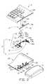
- FIG. 2is an exploded, isometric view of a connecting structure received in the main device of FIG. 1 in accordance with one embodiment of present disclosure.
- FIG. 3is a partially exploded, isometric view of the connecting structure of FIG. 2 .
- FIG. 4is an assembled, isometric, top view of the connecting structure of FIG. 3 , when the auxiliary apparatus is connected to the main device.
- FIG. 5is an assembled, isometric, top view of the connecting structure of FIG. 3 , when the auxiliary apparatus is disconnected from the main device.
- FIG. 6is an isometric view of the main device connecting the auxiliary apparatus by clamping an outer sidewall of the auxiliary apparatus.
- a connecting structure 3in accordance with an exemplary embodiment, is received in a main device 2 for connecting an auxiliary apparatus 5 .
- the main device 2includes a receiving case 22 and a cover 20 to cover the receiving case 22 .
- the receiving case 22includes a bottom board 21 and a sidewall 25 perpendicularly connected to the bottom board 21 , and defines an opening 220 on the sidewall 25 .
- the connecting structure 3includes a retracting part 7 and a clamping part 9 . The retracting part 7 is set on the bottom board 21 and close to the opening 220 .
- the retracting part 7drives the clamping part 9 to extend out of the receiving case 22 via the opening 220 for connecting the auxiliary apparatus 5 when the auxiliary apparatus 5 needs to be mounted on the main device 2 .
- the retracting part 7retracts the clamping part 9 into the receiving case 22 when the auxiliary apparatus 5 is dismounted from the main device 2 .
- the main device 2may be an electronic device, such as a computer or a mobile phone, etc.
- the auxiliary apparatus 5may be an accessory of the electronic device.
- the main device 2is a keyboard and the auxiliary apparatus 5 is a mouse.
- the retracting part 7includes a door mechanism 4 , a transmission mechanism 71 , and a pair of resilient elements 8 .
- the door mechanism 4includes a first button 44 , a positioning board 42 , a movable board 40 , and a number of restoring springs 41 .
- the positioning board 42is perpendicularly fixed on the bottom board 21 near the opening 220 and faces an internal side of the sidewall 25 .
- a receiving gap 46is defined between the positioning board 42 and the sidewall 25 .
- the positioning board 42defines a through hole 420 corresponding to the opening 220 therein.
- the shape of the through hole 420is substantially the same as the shape of the opening 220 .
- the positioning board 42defines a cutout 422 at the middle part of a periphery of the through hole 420 closest to the bottom board 21 .
- the movable board 40is substantially rectangular, and extends an engaging arm 400 from a side surface of the movable board 40 towards an interior of the receiving case 22 .
- the movable board 40is received in the receiving gap 46 with the engaging arm 400 aligning with the cutout 422 .
- a bottom periphery of the movable board 40is connected to the bottom board 21 via the restoring springs 41 .
- the movable board 40can resiliently move along a direction perpendicularly to the bottom board 21 .
- the first button 44is set on the cover 20 and aligns with the engaging arm 400 . When the first button 44 is not pressed, the first button 44 is separated from the engaging arm 400 . The movable board 40 blocks the opening 220 . When the first button 44 is pressed downward, the first button 44 contacts the engaging arm 400 and pushes the engaging arm 400 to move downward in the cutout 422 . The movable board 40 is then driven to move downwards and expose the opening 220 .
- the transmission mechanism 71includes a second button 70 , a transmission block 72 , a pair of first transmission rods 73 , a pair of second transmission rods 74 , and a pair of third transmission rods 75 .
- the transmission block 72includes a main body 722 and a connecting shaft 721 extending from one end surface of the main body 722 .
- the main body 722is substantially triangular, and includes a pair of inclined engaging side surfaces 723 .
- the connecting shaft 721is connected to the second button 70 set on the cover 20 .
- the pair of first transmission rods 73are correspondingly sleeved in a pair of guiding blocks 23 formed on the bottom board 21 and slide along a direction parallel to the sidewall 25 in which the opening 220 is defined.
- Each of the first transmission rods 73includes an inclined engaging end surface 730 facing the other first transmission rod 73 and a first connecting end 732 opposite to the engaging end surface 730 .
- An engaging gap 733is defined between a pair of engaging end surfaces 730 facing each other.
- a pair of screwing bumps 24are formed on the bottom board 21 and positioned between the guiding blocks 23 and the opening 220 .
- Each of the second transmission rods 74includes a second connecting end 740 and a third connecting end 742 opposite to the second connecting end 740 .
- the second connecting end 740 of each second transmission rod 74is pivotablly connected to the first connecting end 732 .
- Each of the second transmission rods 74is pivotablly connected to one of the screwing bumps 24 at a rotation joint 244 of the second transmission rod 74 formed between the second connecting end 740 and the third connecting end 742 .
- a distance between the rotation joint 244 and the second connecting end 740is less than the distance between the rotation joint 244 and the third connecting end 742 .
- the clamping part 9includes a pair of clamps 90 and a pair of first screwing posts 27 .
- Each of the clamps 90includes a sixth connecting end 900 and a clamping end 902 opposite to the sixth connecting end 900 .
- the first screwing posts 27are formed on the bottom board 21 and positioned in an area surrounded by the first transmission rods 73 and the second transmission rods 74 .
- the sixth connecting end 900 of each clamp 90is pivotablly connected to a top end of the first screwing post 27 .
- the height of the first screwing post 27is equal to the distance between the opening 220 and the bottom board 21 .
- the clamping end 902can extend out of the receiving case 22 via the opening 220 when the clamps 90 rotate to a position where the clamp 90 is perpendicular to the sidewall 25 . Because the first screwing posts 27 are higher than the screwing bumps 24 , the clamps 90 rotate above a plane defined by the first transmission rods 73 , the second transmission rods 74 and the third transmission rods 75 .
- Each of the third transmission rods 75includes a fourth connecting end 750 and a fifth connecting end 752 opposite to the fourth connecting end 750 .
- the fourth connecting end 750 of each third transmission rod 75is pivotablly connected to the third connecting end 742 .
- the third transmission rods 742are correspondingly pivotably connected to the clamps 90 via a pair of shafts correspondingly extending upwards from the fifth connecting ends 752 .
- a pair of second screwing posts 28are formed on the bottom board 21 and positioned between the pair of first screwing posts 27 .
- a distance between the second screwing posts 28 and the first transmission rods 73is less than the distance between the first screwing posts 27 and the first transmission rods 73 .
- One end of each resilient element 8is correspondingly connected to a top end of one of the second screwing posts 28 .
- the other end of each resilient element 8is correspondingly connected to a connection joint 904 of one of the clamps 90 .
- the connection joint 904is between the third transmission rod 75 and the clamping end 902 .
- the first button 44is pressed downwards to drive the movable board 40 to move downwards and expose the opening 220 .
- the resilient elements 8correspondingly push the pair of clamps 90 to rotate apart from each other.
- the clamping end 902 of each clamp 90stretches out of the receiving case 22 via the opening 220 to connect with the auxiliary apparatus 5 .
- the auxiliary apparatus 5includes an engaging structure 50 , for example a pair of hooks, formed on an outer sidewall of the auxiliary apparatus 5 .
- the clamping ends 902 of the main device 2can easily connect with the auxiliary apparatus 5 via the engaging structures 50 .
- the clamping ends 902can directly hug the outer sidewall of the auxiliary apparatus 5 , and the engaging structures 50 are omitted.
- the second button 70is pressed downwards to allow the transmission block 72 to move downwards.
- the transmission block 72is inserted into the engaging gap 733 (see FIG. 2 ), the inclined engaging side surfaces 730 correspondingly slidably engage with the inclined engaging end surface 723 to drive the pair of first transmission rods 73 to slide apart from each other.
- the pair of second transmission rods 74is driven to rotate towards each other by the first transmission rods 73 .
- the second transmission rods 74correspondingly drive the pair of clamps 90 to rotate towards each other via the pair of third transmission rods 75 .
- the resilient elements 8are compressed when the pair of clamps 90 rotate towards each other.
- the movable board 40When the clamping ends 902 are totally retracted in the receiving case 22 , the movable board 40 is forced to move upwards by the restoring springs 41 and blocks the opening 220 . Then, the clamping ends 902 resist against the movable board 40 under a restoring force of the resilient elements 8 . Next time the movable board 40 exposes the opening 220 , the clamping ends 902 will extend out of the receiving case 22 under the restoring force of the resilient elements 8 .
Landscapes
- Engineering & Computer Science (AREA)
- General Engineering & Computer Science (AREA)
- Theoretical Computer Science (AREA)
- Human Computer Interaction (AREA)
- Physics & Mathematics (AREA)
- General Physics & Mathematics (AREA)
- Computer Hardware Design (AREA)
- Clamps And Clips (AREA)
- Toys (AREA)
- Lock And Its Accessories (AREA)
Abstract
Description
Claims (12)
Applications Claiming Priority (3)
| Application Number | Priority Date | Filing Date | Title |
|---|---|---|---|
| CN201110437365 | 2011-12-23 | ||
| CN201110437365.7 | 2011-12-23 | ||
| CN 201110437365CN103179833A (en) | 2011-12-23 | 2011-12-23 | Device with telescoping mechanism |
Publications (2)
| Publication Number | Publication Date |
|---|---|
| US20130161461A1 US20130161461A1 (en) | 2013-06-27 |
| US9038974B2true US9038974B2 (en) | 2015-05-26 |
Family
ID=48639367
Family Applications (1)
| Application Number | Title | Priority Date | Filing Date |
|---|---|---|---|
| US13/585,893Expired - Fee RelatedUS9038974B2 (en) | 2011-12-23 | 2012-08-15 | Connecting structure |
Country Status (3)
| Country | Link |
|---|---|
| US (1) | US9038974B2 (en) |
| CN (1) | CN103179833A (en) |
| TW (1) | TW201327605A (en) |
Families Citing this family (5)
| Publication number | Priority date | Publication date | Assignee | Title |
|---|---|---|---|---|
| US9602063B2 (en) | 2013-03-12 | 2017-03-21 | Peregrine Semiconductor Corporation | Variable impedance match and variable harmonic terminations for different modes and frequency bands |
| CN104571536A (en)* | 2013-10-10 | 2015-04-29 | 宁夏先锋软件有限公司 | Computer keyboard with adjustable key touch feeling |
| US10215206B2 (en)* | 2016-05-30 | 2019-02-26 | Nanning Fugui Precision Industrial Co., Ltd. | Connecting structure for electronic devices |
| CN110360195B (en)* | 2019-06-05 | 2021-09-14 | 联想(北京)有限公司 | Connecting structure |
| CN110418533B (en)* | 2019-08-20 | 2020-11-13 | 维沃移动通信有限公司 | Electronic device |
Citations (21)
| Publication number | Priority date | Publication date | Assignee | Title |
|---|---|---|---|---|
| US5704698A (en)* | 1996-02-07 | 1998-01-06 | Lin; Chin-Chih | Keyboard slide structure with removable palm rest and slide rail means |
| US5995082A (en)* | 1994-11-15 | 1999-11-30 | Lakoski; Robert P. | Removable pad for portable computer |
| US6128186A (en)* | 1998-07-17 | 2000-10-03 | Feierbach; Wolfgang R. | Ergonomic computer workstations |
| US6163326A (en)* | 1998-02-26 | 2000-12-19 | Micron Electronics, Inc. | Input device for a laptop computer |
| US6442019B1 (en)* | 1999-04-16 | 2002-08-27 | Sungjin C & C, Ltd. | Computer having a built-in mouse rack |
| US20020167482A1 (en)* | 2001-05-14 | 2002-11-14 | Yin Memphis Zhihong | Portable computer system including detachable peripheral device and combined mouse/joystick for use with same |
| US20060082553A1 (en)* | 2004-10-14 | 2006-04-20 | Hsuan-Yu Lin | Mouse device of a laptop computer |
| US20070014083A1 (en)* | 2005-07-15 | 2007-01-18 | Fujitsu Limited | Electronic apparatus and unit mounting mechanism |
| US20070132731A1 (en)* | 2005-12-09 | 2007-06-14 | Primax Electronics Ltd. | Mouse having storable hook module |
| US7330923B2 (en)* | 2005-03-21 | 2008-02-12 | Avago Technologies Ecbu Ip (Singapore) Pte. Ltd. | Input devices and methods of operating same |
| US20080310094A1 (en)* | 2007-03-19 | 2008-12-18 | James Allen Burns | Attachable device accessory case cover with interchangeable components |
| US20090002320A1 (en)* | 2005-03-23 | 2009-01-01 | Daniel David Karmazyn | Keyboard With Surface for Computer Mouse Operation and Moveable Numeric Keypad |
| US7494351B2 (en)* | 2006-08-25 | 2009-02-24 | Primax Electronics Ltd. | Connector for attachment of a peripheral device to a computer |
| US20090244836A1 (en)* | 2008-03-31 | 2009-10-01 | Tung-Lin Leng | Attach a Mobile Mouse to Your Laptop |
| US20100085705A1 (en)* | 2008-10-03 | 2010-04-08 | Coretronic Corporation | Keyboard set having a micro projector |
| US20100246119A1 (en)* | 2009-03-27 | 2010-09-30 | Qualcomm Incorporated | Portable docking station for a portable computing device |
| US20100250816A1 (en)* | 2009-03-27 | 2010-09-30 | Qualcomm Incorporated | System and method of managing displays at a portable computing device and a portable computing device docking station |
| US7948741B2 (en)* | 2009-06-29 | 2011-05-24 | Hong Fu Jin Precision Industry (Shenzhen) Co., Ltd. | Electronic device with detachable touchpad |
| US20110235275A1 (en)* | 2010-03-26 | 2011-09-29 | Wistron Corporation | Portable electronic device having a pop-up keyboard cross-reference to related application |
| US20120155003A1 (en)* | 2010-12-16 | 2012-06-21 | King Fahd University Of Petroleum And Minerals | Retractable mouse pad for computers |
| US20130120923A1 (en)* | 2011-11-15 | 2013-05-16 | Hon Hai Precision Industry Co., Ltd. | Latching mechanism, wrist rest and keyboard assembly |
- 2011
- 2011-12-23CNCN 201110437365patent/CN103179833A/enactivePending
- 2011-12-26TWTW100148718Apatent/TW201327605A/enunknown
- 2012
- 2012-08-15USUS13/585,893patent/US9038974B2/ennot_activeExpired - Fee Related
Patent Citations (21)
| Publication number | Priority date | Publication date | Assignee | Title |
|---|---|---|---|---|
| US5995082A (en)* | 1994-11-15 | 1999-11-30 | Lakoski; Robert P. | Removable pad for portable computer |
| US5704698A (en)* | 1996-02-07 | 1998-01-06 | Lin; Chin-Chih | Keyboard slide structure with removable palm rest and slide rail means |
| US6163326A (en)* | 1998-02-26 | 2000-12-19 | Micron Electronics, Inc. | Input device for a laptop computer |
| US6128186A (en)* | 1998-07-17 | 2000-10-03 | Feierbach; Wolfgang R. | Ergonomic computer workstations |
| US6442019B1 (en)* | 1999-04-16 | 2002-08-27 | Sungjin C & C, Ltd. | Computer having a built-in mouse rack |
| US20020167482A1 (en)* | 2001-05-14 | 2002-11-14 | Yin Memphis Zhihong | Portable computer system including detachable peripheral device and combined mouse/joystick for use with same |
| US20060082553A1 (en)* | 2004-10-14 | 2006-04-20 | Hsuan-Yu Lin | Mouse device of a laptop computer |
| US7330923B2 (en)* | 2005-03-21 | 2008-02-12 | Avago Technologies Ecbu Ip (Singapore) Pte. Ltd. | Input devices and methods of operating same |
| US20090002320A1 (en)* | 2005-03-23 | 2009-01-01 | Daniel David Karmazyn | Keyboard With Surface for Computer Mouse Operation and Moveable Numeric Keypad |
| US20070014083A1 (en)* | 2005-07-15 | 2007-01-18 | Fujitsu Limited | Electronic apparatus and unit mounting mechanism |
| US20070132731A1 (en)* | 2005-12-09 | 2007-06-14 | Primax Electronics Ltd. | Mouse having storable hook module |
| US7494351B2 (en)* | 2006-08-25 | 2009-02-24 | Primax Electronics Ltd. | Connector for attachment of a peripheral device to a computer |
| US20080310094A1 (en)* | 2007-03-19 | 2008-12-18 | James Allen Burns | Attachable device accessory case cover with interchangeable components |
| US20090244836A1 (en)* | 2008-03-31 | 2009-10-01 | Tung-Lin Leng | Attach a Mobile Mouse to Your Laptop |
| US20100085705A1 (en)* | 2008-10-03 | 2010-04-08 | Coretronic Corporation | Keyboard set having a micro projector |
| US20100246119A1 (en)* | 2009-03-27 | 2010-09-30 | Qualcomm Incorporated | Portable docking station for a portable computing device |
| US20100250816A1 (en)* | 2009-03-27 | 2010-09-30 | Qualcomm Incorporated | System and method of managing displays at a portable computing device and a portable computing device docking station |
| US7948741B2 (en)* | 2009-06-29 | 2011-05-24 | Hong Fu Jin Precision Industry (Shenzhen) Co., Ltd. | Electronic device with detachable touchpad |
| US20110235275A1 (en)* | 2010-03-26 | 2011-09-29 | Wistron Corporation | Portable electronic device having a pop-up keyboard cross-reference to related application |
| US20120155003A1 (en)* | 2010-12-16 | 2012-06-21 | King Fahd University Of Petroleum And Minerals | Retractable mouse pad for computers |
| US20130120923A1 (en)* | 2011-11-15 | 2013-05-16 | Hon Hai Precision Industry Co., Ltd. | Latching mechanism, wrist rest and keyboard assembly |
Also Published As
| Publication number | Publication date |
|---|---|
| CN103179833A (en) | 2013-06-26 |
| US20130161461A1 (en) | 2013-06-27 |
| TW201327605A (en) | 2013-07-01 |
Similar Documents
| Publication | Publication Date | Title |
|---|---|---|
| US8801441B2 (en) | Pop-up mechanism having a button and sliding pillars | |
| US9038974B2 (en) | Connecting structure | |
| US8231162B2 (en) | Clamp mechanism | |
| US8840410B2 (en) | Pop-up mechanism having a sliding pushing pillar coupled to a spring | |
| US7311541B2 (en) | Electronic connector | |
| US8215595B2 (en) | Cable collecting apparatus | |
| US8526191B2 (en) | Assembly apparatus and electronic device using the same | |
| US9296091B2 (en) | Jig for securing thimble | |
| US20110128693A1 (en) | Mounting apparatus and electronic device incorporating the same | |
| US8248817B2 (en) | Computer chassis for mounting motherboard therein | |
| US20120049011A1 (en) | Cable management apparatus | |
| US8272609B2 (en) | Heat sink bracket | |
| US11892028B2 (en) | Fastening assembly and board-to-board assembled structure | |
| US8500485B2 (en) | Fixing apparatus for connector | |
| US8251750B2 (en) | Adapter apparatus | |
| US9235231B2 (en) | Workpiece separating device | |
| US7933124B2 (en) | Electronic device with expansion card fasterning device | |
| US20130240089A1 (en) | Stamping die with connecting member | |
| US8520369B2 (en) | Method and protecting apparatus for disassembling electronic device | |
| US8621971B2 (en) | Cutting apparatus with adjustable mechanism | |
| US20120017738A1 (en) | Cutting apparatus | |
| CN212034211U (en) | Camera lifting and turning device and intelligent terminal equipment | |
| US20130134845A1 (en) | Mounting apparatus for data storage device | |
| US20130162121A1 (en) | Electronic device enclosure | |
| US20120210807A1 (en) | Testing module |
Legal Events
| Date | Code | Title | Description |
|---|---|---|---|
| AS | Assignment | Owner name:HON HAI PRECISION INDUSTRY CO., LTD., TAIWAN Free format text:ASSIGNMENT OF ASSIGNORS INTEREST;ASSIGNORS:CHOU, CHE-YU;HUANG, QUN;ZHU, TAI-SHAN;AND OTHERS;REEL/FRAME:028788/0166 Effective date:20120809 Owner name:FU TAI HUA INDUSTRY (SHENZHEN) CO., LTD., CHINA Free format text:ASSIGNMENT OF ASSIGNORS INTEREST;ASSIGNORS:CHOU, CHE-YU;HUANG, QUN;ZHU, TAI-SHAN;AND OTHERS;REEL/FRAME:028788/0166 Effective date:20120809 | |
| STCF | Information on status: patent grant | Free format text:PATENTED CASE | |
| MAFP | Maintenance fee payment | Free format text:PAYMENT OF MAINTENANCE FEE, 4TH YEAR, LARGE ENTITY (ORIGINAL EVENT CODE: M1551); ENTITY STATUS OF PATENT OWNER: LARGE ENTITY Year of fee payment:4 | |
| FEPP | Fee payment procedure | Free format text:MAINTENANCE FEE REMINDER MAILED (ORIGINAL EVENT CODE: REM.); ENTITY STATUS OF PATENT OWNER: LARGE ENTITY | |
| LAPS | Lapse for failure to pay maintenance fees | Free format text:PATENT EXPIRED FOR FAILURE TO PAY MAINTENANCE FEES (ORIGINAL EVENT CODE: EXP.); ENTITY STATUS OF PATENT OWNER: LARGE ENTITY | |
| STCH | Information on status: patent discontinuation | Free format text:PATENT EXPIRED DUE TO NONPAYMENT OF MAINTENANCE FEES UNDER 37 CFR 1.362 | |
| FP | Lapsed due to failure to pay maintenance fee | Effective date:20230526 |