US9038350B2 - One-piece dovetail veneer tie and wall anchoring system with in-cavity thermal breaks - Google Patents
One-piece dovetail veneer tie and wall anchoring system with in-cavity thermal breaksDownload PDFInfo
- Publication number
- US9038350B2 US9038350B2US14/046,556US201314046556AUS9038350B2US 9038350 B2US9038350 B2US 9038350B2US 201314046556 AUS201314046556 AUS 201314046556AUS 9038350 B2US9038350 B2US 9038350B2
- Authority
- US
- United States
- Prior art keywords
- veneer tie
- anchoring system
- thermally
- insertion portion
- securement
- Prior art date
- Legal status (The legal status is an assumption and is not a legal conclusion. Google has not performed a legal analysis and makes no representation as to the accuracy of the status listed.)
- Expired - Fee Related
Links
- 238000004873anchoringMethods0.000titleclaimsabstractdescription65
- 239000011248coating agentSubstances0.000claimsabstractdescription53
- 238000000576coating methodMethods0.000claimsabstractdescription53
- 239000002184metalSubstances0.000claimsabstractdescription23
- 229910052751metalInorganic materials0.000claimsabstractdescription23
- 239000000463materialSubstances0.000claimsabstractdescription12
- 238000009413insulationMethods0.000claimsdescription52
- 238000003780insertionMethods0.000claimsdescription29
- 230000037431insertionEffects0.000claimsdescription29
- 230000002787reinforcementEffects0.000claimsdescription26
- 238000012546transferMethods0.000claimsdescription20
- 238000009434installationMethods0.000claimsdescription9
- 229910001335Galvanized steelInorganic materials0.000claimsdescription8
- 239000008397galvanized steelSubstances0.000claimsdescription8
- 229910000831SteelInorganic materials0.000claimsdescription6
- 239000010959steelSubstances0.000claimsdescription6
- 229910001092metal group alloyInorganic materials0.000claimsdescription4
- 239000010935stainless steelSubstances0.000claimsdescription4
- 229910001220stainless steelInorganic materials0.000claimsdescription4
- 150000001875compoundsChemical class0.000claimsdescription3
- 229920002943EPDM rubberPolymers0.000claimsdescription2
- 239000004593EpoxySubstances0.000claimsdescription2
- 229920006397acrylic thermoplasticPolymers0.000claimsdescription2
- 229920001971elastomerPolymers0.000claimsdescription2
- 125000003700epoxy groupChemical group0.000claimsdescription2
- 239000000835fiberSubstances0.000claimsdescription2
- 229920001778nylonPolymers0.000claimsdescription2
- 229920003229poly(methyl methacrylate)Polymers0.000claimsdescription2
- 229920000647polyepoxidePolymers0.000claimsdescription2
- 229920000728polyesterPolymers0.000claimsdescription2
- 229920000642polymerPolymers0.000claimsdescription2
- 229920001296polysiloxanePolymers0.000claimsdescription2
- 229920000915polyvinyl chloridePolymers0.000claimsdescription2
- 229920005989resinPolymers0.000claimsdescription2
- 239000011347resinSubstances0.000claimsdescription2
- 239000005060rubberSubstances0.000claimsdescription2
- ISXSCDLOGDJUNJ-UHFFFAOYSA-Ntert-butyl prop-2-enoateChemical compoundCC(C)(C)OC(=O)C=CISXSCDLOGDJUNJ-UHFFFAOYSA-N0.000claimsdescription2
- 229920001169thermoplasticPolymers0.000claimsdescription2
- 229920001187thermosetting polymerPolymers0.000claimsdescription2
- 239000004416thermosoftening plasticSubstances0.000claimsdescription2
- 238000005452bendingMethods0.000claims1
- 238000000034methodMethods0.000abstractdescription4
- 238000010276constructionMethods0.000description13
- 239000011449brickSubstances0.000description11
- 239000004570mortar (masonry)Substances0.000description7
- 230000008901benefitEffects0.000description6
- 239000004567concreteSubstances0.000description6
- 230000005540biological transmissionEffects0.000description5
- 238000009833condensationMethods0.000description5
- 230000005494condensationEffects0.000description5
- 238000011161developmentMethods0.000description5
- 230000018109developmental processEffects0.000description5
- 230000000694effectsEffects0.000description5
- 230000004888barrier functionEffects0.000description4
- 238000002955isolationMethods0.000description4
- 230000008859changeEffects0.000description3
- 239000002131composite materialSubstances0.000description3
- 238000001816coolingMethods0.000description3
- 238000010438heat treatmentMethods0.000description3
- 230000037361pathwayEffects0.000description3
- 238000002485combustion reactionMethods0.000description2
- 230000001143conditioned effectEffects0.000description2
- 230000007797corrosionEffects0.000description2
- 238000005260corrosionMethods0.000description2
- 238000013461designMethods0.000description2
- 238000005516engineering processMethods0.000description2
- 238000011156evaluationMethods0.000description2
- 239000012530fluidSubstances0.000description2
- 230000006872improvementEffects0.000description2
- 230000008595infiltrationEffects0.000description2
- 238000001764infiltrationMethods0.000description2
- 239000012212insulatorSubstances0.000description2
- 238000011835investigationMethods0.000description2
- 238000004519manufacturing processMethods0.000description2
- 150000002739metalsChemical class0.000description2
- 230000009972noncorrosive effectEffects0.000description2
- 238000007789sealingMethods0.000description2
- 229920002430Fibre-reinforced plasticPolymers0.000description1
- 229910000746Structural steelInorganic materials0.000description1
- 210000001015abdomenAnatomy0.000description1
- 238000007792additionMethods0.000description1
- 239000000853adhesiveSubstances0.000description1
- 230000001070adhesive effectEffects0.000description1
- 238000004378air conditioningMethods0.000description1
- 238000004458analytical methodMethods0.000description1
- 230000015572biosynthetic processEffects0.000description1
- 230000001010compromised effectEffects0.000description1
- 230000008602contractionEffects0.000description1
- 238000004132cross linkingMethods0.000description1
- 230000007423decreaseEffects0.000description1
- 230000006735deficitEffects0.000description1
- 230000006866deteriorationEffects0.000description1
- 238000009826distributionMethods0.000description1
- 230000009977dual effectEffects0.000description1
- 238000001125extrusionMethods0.000description1
- 230000002349favourable effectEffects0.000description1
- 239000011151fibre-reinforced plasticSubstances0.000description1
- 239000005002finish coatingSubstances0.000description1
- 238000009432framingMethods0.000description1
- 238000010348incorporationMethods0.000description1
- 238000007689inspectionMethods0.000description1
- 230000002452interceptive effectEffects0.000description1
- 235000000396ironNutrition0.000description1
- 231100000053low toxicityToxicity0.000description1
- 239000012528membraneSubstances0.000description1
- 238000012986modificationMethods0.000description1
- 230000004048modificationEffects0.000description1
- 239000000843powderSubstances0.000description1
- 238000002360preparation methodMethods0.000description1
- 230000008569processEffects0.000description1
- 238000012545processingMethods0.000description1
- 230000009467reductionEffects0.000description1
- 230000003014reinforcing effectEffects0.000description1
- 238000009418renovationMethods0.000description1
- 230000004044responseEffects0.000description1
- 238000012552reviewMethods0.000description1
- 230000035939shockEffects0.000description1
- 239000000779smokeSubstances0.000description1
- 239000004575stoneSubstances0.000description1
- 238000012360testing methodMethods0.000description1
- 238000007751thermal sprayingMethods0.000description1
- 231100000331toxicToxicity0.000description1
- 230000002588toxic effectEffects0.000description1
- 230000001988toxicityEffects0.000description1
- 231100000419toxicityToxicity0.000description1
- XLYOFNOQVPJJNP-UHFFFAOYSA-NwaterSubstancesOXLYOFNOQVPJJNP-UHFFFAOYSA-N0.000description1
Images


Classifications
- E—FIXED CONSTRUCTIONS
- E04—BUILDING
- E04B—GENERAL BUILDING CONSTRUCTIONS; WALLS, e.g. PARTITIONS; ROOFS; FLOORS; CEILINGS; INSULATION OR OTHER PROTECTION OF BUILDINGS
- E04B1/00—Constructions in general; Structures which are not restricted either to walls, e.g. partitions, or floors or ceilings or roofs
- E04B1/62—Insulation or other protection; Elements or use of specified material therefor
- E04B1/74—Heat, sound or noise insulation, absorption, or reflection; Other building methods affording favourable thermal or acoustical conditions, e.g. accumulating of heat within walls
- E04B1/76—Heat, sound or noise insulation, absorption, or reflection; Other building methods affording favourable thermal or acoustical conditions, e.g. accumulating of heat within walls specifically with respect to heat only
- E04B1/7608—Heat, sound or noise insulation, absorption, or reflection; Other building methods affording favourable thermal or acoustical conditions, e.g. accumulating of heat within walls specifically with respect to heat only comprising a prefabricated insulating layer, disposed between two other layers or panels
- E04B1/7612—Heat, sound or noise insulation, absorption, or reflection; Other building methods affording favourable thermal or acoustical conditions, e.g. accumulating of heat within walls specifically with respect to heat only comprising a prefabricated insulating layer, disposed between two other layers or panels in combination with an air space
- E04B1/7616—Heat, sound or noise insulation, absorption, or reflection; Other building methods affording favourable thermal or acoustical conditions, e.g. accumulating of heat within walls specifically with respect to heat only comprising a prefabricated insulating layer, disposed between two other layers or panels in combination with an air space with insulation-layer locating devices combined with wall ties
- E—FIXED CONSTRUCTIONS
- E04—BUILDING
- E04B—GENERAL BUILDING CONSTRUCTIONS; WALLS, e.g. PARTITIONS; ROOFS; FLOORS; CEILINGS; INSULATION OR OTHER PROTECTION OF BUILDINGS
- E04B1/00—Constructions in general; Structures which are not restricted either to walls, e.g. partitions, or floors or ceilings or roofs
- E04B1/38—Connections for building structures in general
- E04B1/41—Connecting devices specially adapted for embedding in concrete or masonry
- E04B1/4178—Masonry wall ties
- E—FIXED CONSTRUCTIONS
- E04—BUILDING
- E04B—GENERAL BUILDING CONSTRUCTIONS; WALLS, e.g. PARTITIONS; ROOFS; FLOORS; CEILINGS; INSULATION OR OTHER PROTECTION OF BUILDINGS
- E04B1/00—Constructions in general; Structures which are not restricted either to walls, e.g. partitions, or floors or ceilings or roofs
- E04B1/62—Insulation or other protection; Elements or use of specified material therefor
- E04B1/92—Protection against other undesired influences or dangers
- E04B1/98—Protection against other undesired influences or dangers against vibrations or shocks; against mechanical destruction, e.g. by air-raids
- E—FIXED CONSTRUCTIONS
- E04—BUILDING
- E04B—GENERAL BUILDING CONSTRUCTIONS; WALLS, e.g. PARTITIONS; ROOFS; FLOORS; CEILINGS; INSULATION OR OTHER PROTECTION OF BUILDINGS
- E04B2/00—Walls, e.g. partitions, for buildings; Wall construction with regard to insulation; Connections specially adapted to walls
- E04B2/02—Walls, e.g. partitions, for buildings; Wall construction with regard to insulation; Connections specially adapted to walls built-up from layers of building elements
- E04B2/28—Walls having cavities between, but not in, the elements; Walls of elements each consisting of two or more parts kept in distance by means of spacers, all parts being solid
- E04B2/30—Walls having cavities between, but not in, the elements; Walls of elements each consisting of two or more parts kept in distance by means of spacers, all parts being solid using elements having specially designed means for stabilising the position; Spacers for cavity walls
Definitions
- This inventionrelates to an improved anchoring arrangement for use in conjunction with building structures having a masonry construction outer wythe anchored to a masonry inner wythe with a dovetail slot anchor secured therewithin. More particularly, the invention relates to an anchoring system that interconnects with a one-piece dovetail veneer tie.
- the one-piece dovetail tieis designed to receive a thermal coating.
- the inventionis applicable to seismic-resistant structures as well as to structures requiring insulation.
- the present inventionsimplifies installation of a veneer anchoring system by reducing the number of parts required for production and installation at the worksite. Additionally, the one-piece nature of the veneer tie provides high-strength support by removing the separate interconnection component of the dovetail anchoring system, a common source of veneer tie failure. Further, the dovetail tail is designed to receive a thermal coating, thereby providing thermal isolation within the wall and providing an energy efficient anchoring system.
- Anchors and tiesare generally placed in one of the following five categories: corrugated; sheet metal; wire; two-piece adjustable; or joint reinforcing.
- the present inventionhas a focus on sheet metal veneer ties.
- surface-mounted wall anchorswere developed by Hohmann & Barnard, Inc., now a MiTEK-Berkshire Hathaway Company, and patented under U.S. Pat. No. 4,598,518.
- the inventionwas commercialized under trademarks DW-10®, DW-10-X®, and DW-10-HS®. These widely accepted building specialty products were designed primarily for dry-wall construction, but were also used with masonry inner wythes.
- the surface-mounted wall anchor of the above-described systemhas pronged legs that pierce the insulation and the wallboard and rest against the metal stud to provide mechanical stability in a four-point landing arrangement.
- the vertical slot of the wall anchorenables the mason to have the wire tie adjustably positioned along a pathway of up to 3.625-inch (max.).
- the interlock systemserved well and received high scores in testing and engineering evaluations which examined effects of various forces, particularly lateral forces, upon brick veneer masonry construction. However, under certain conditions, the system did not sufficiently maintain the integrity of the insulation.
- a seismic veneer anchorwhich incorporated an L-shaped backplate, was introduced. This was formed from either 12- or 14-gauge sheetmetal and provided horizontally disposed openings in the arms thereof for pintle legs of the veneer anchor.
- the pintle-receiving sheetmetal version of the Seismiclip interlock systemserved well, but in addition to the insulation integrity problem, installations were hampered by mortar buildup interfering with pintle leg insertion.
- wire formativeshave been limited by the mortar layer thickness which, in turn are dictated either by the new building specifications or by pre-existing conditions, e.g. matching during renovations or additions to the existing mortar layer thickness. While arguments have been made for increasing the number of the fine-wire anchors per unit area of the facing layer, architects and architectural engineers have favored wire formative anchors of sturdier wire.
- the high-strength veneer tie of this inventionis specially configured to prevent veneer tie failure and resultant pullout.
- the configured tierestricts pull out and horizontal movement while allowing adjustment in the vertical direction, ensuring a high-strength connection and transfer of forces between the outer wythe and the inner wythe.
- the move toward more energy-efficient insulated cavity wall structureshas led to the need to create a thermally isolated building envelope which separates the interior environment and the exterior environment of a cavity wall structure.
- the building envelopeis designed to control temperature, thermal transfer between the wythes and moisture development, while maintaining structural integrity.
- Thermal insulationis used within the building envelope to maintain temperature and therefore restrict the formation of condensation within the cavity.
- the integrity of the thermal insulationis compromised when used in conjunction with the prior art metal anchoring system, which are constructed from thermally conductive metals that cause thermal transfer between and through the wythes.
- the use of the specially designed and thermally-protected veneer ties of the present inventionlower the metal thermal conductivities and thereby reduce thermal transfer.
- each anchor and tie combinationforms a thermal bridge, perforating the insulation and moisture barriers within the cavity wall structure. While seals at the insertion locations can deter water and vapor entry, thermal transfer and loss still result.
- each individual anchoring systemsis interconnected veneer-tie-to-wall-anchor, a thermal thread results stretching across the cavity and extending between the inner wythe and the outer wythe. Failure to isolate the steel components and break the thermal transfer, results in heating and cooling losses and potentially damaging condensation buildup within the cavity wall structure. Such buildups provide a medium for corrosion and mold growth.
- the use of a thermally-isolating coated veneer tieremoves the thermal bridges and breaks the thermal thread resulting in a thermally-isolated anchoring system and resulting lower heat loss within the building envelope.
- the present inventionprovides a thermally-isolating coated veneer tie specially-suited for use within a cavity wall.
- Anchoring systems within cavity wallsare subject to outside forces such as earthquakes and wind shear that cause abrupt movement within the cavity wall. Additionally, any materials placed within the cavity wall require the characteristics of low flammability and, upon combustion, the release of combustion products with low toxicity.
- the present inventionprovides a coating suited to such requirements, which, besides meeting the flammability/toxicity standards, includes characteristics such as shock resistance, non-frangibility, low thermal conductivity and transmissivity, and a non-porous resilient finish. This unique combination of characteristics provides a veneer tie well-suited for installation within a cavity wall anchoring system.
- the underlying sheetmetal plateis highly thermally conductive, and the '581 patent describes lowering the thermal conductivity by foraminously structuring the plate.
- a concomitant loss of the insulative integrityresults.
- Further reductions in thermal transferwere accomplished through the Byna-Tie® system ('319) which provides a bail handle with pointed legs and a dual sealing arrangement, U.S. Pat. No. 8,037,653.
- a specialized thermally-isolating coated veneer tiewhich removes thermal bridging and improves thermal insulation through the use of a thermal barrier.
- the presently presented thermal tieis optionally provided with a matte-finish coating to provide pullout resistance.
- thermal characteristics of cavity wall constructionis important to ensuring minimized heat transfer through the walls, both for comfort and for energy efficiency of heating and air conditioning.
- heat from the interiorshould be prevented from passing through the outside.
- heat from the exteriorshould be prevented from passing through to the interior.
- the main cause of thermal transferis the use of anchoring systems made largely of metals that are thermally conductive. While providing the required high-strength within the cavity wall system, the use of steel components results in heat transfer.
- the cavity wallserves additionally as a plenum for delivering air from one area to another.
- the ability to size cavities to match air moving requirements for naturally ventilated buildingsenable the architectural engineer to now consider cavity walls when designing structures in this environmentally favorable form.
- the underlying metal veneer tieobtains a lower transmission (U-value) and thermal conductive value (K-value) and provides non-corrosive benefits.
- U-valuetransmission
- K-valuethermal conductive value
- a vertical angle ironwith one leg adapted for attachment to a stud; and the other having elongated slots to accommodate wall ties. Insulation is applied between projecting vertical legs of adjacent angle irons with slots being spaced away from the stud to avoid the insulation.
- a veneer wall anchoring systemthat interconnects a backup wall of block construction with a brick veneer wall.
- a wall of rigid insulationis placed against an outer face of the backup wall with the plates extending through the insulation.
- the plateincludes a spring clip fastener which engages the insulation wall.
- a gripstay channel veneer anchor assemblythat engages an insulation layer and the inner wythe.
- a clip securementprojects through the channel, pierces the insulation and engages the support member.
- a cavity-wall anchorhaving a conventional tie wire for mounting in the brick veneer and an L-shaped sheetmetal bracket for mounting vertically between side-by-side blocks and horizontally atop a course of blocks.
- the brackethas a slit which is vertically disposed and protrudes into the cavity. The slit provides for a vertically adjustable anchor.
- a two-part masonry brick tieDiscloses a two-part masonry brick tie, the first part being designed to be installed in the inner wythe and then, later when the brick veneer is erected to be interconnected by the second part. Both parts are constructed from sheetmetal and are arranged on substantially the same horizontal plane.
- the systemincludes a wire formative anchor and box tie.
- the anchorincludes a seismic clip and reinforcement wire and the anchor eye portions are oriented to secure the insulation panels which are protected by insulation shields
- the Charlson systemincludes an insulator adhered to the structural support through the use of adhesives, frictional forces or mechanical fasteners to disrupt thermal activity.
- the composite fastenerincludes a fiber reinforced polymer.
- the fastenerhas a low thermal conductive value and non-corrosive properties.
- an anchor and reinforcement devicefor a cavity wall.
- the deviceinterlocks with a veneer anchor and veneer reinforcements.
- the systemis composed of wire formatives.
- the wall anchor and reinforcement devicesare compressively reduced in height to span insulation mounted on the exterior of the backup wall.
- insulated cavity wall structuresbenefit from the recent developments described herein that lead to solving the problems of veneer tie interconnection failure and maintaining insulation integrity.
- This inventionrelates to an improved anchoring arrangement for use in conjunction with cavity walls having a poured concrete masonry inner wythe and a masonry outer wythe and meets the heretofore unmet needs described above.
- None of the prior art listed aboveprovides a dovetail channel anchoring system which secures the anchor within the inner wythe and provides a high strength interconnection between the inner wythe and outer wythe.
- the wall anchor assemblyprovides a novel one-piece dovetail veneer tie which is readily modifiable to receive a thermally-isolating coating and a seismic reinforcement wire.
- the prior artdoes not provide the present novel cavity wall construction system as described herein below.
- the invention disclosed herebyis a dovetail anchoring system having a one-piece dovetail veneer tie for use in a cavity wall having a masonry outer wythe and an inner wythe or backup wall of poured concrete.
- the wall anchor and veneer tiesecures the outer wythe to the inner wythe.
- the non-invasive high-strength veneer tiedoes not compromise the insulation integrity.
- the veneer tiesare single constructs comprised of sheet metal and configured for insertion within the wall anchor dovetail channels and the bed joints of the outer wythe.
- the veneer tiesinclude a seismic notch for interconnection with a reinforcement wire forming a seismic construct.
- the wall anchoris a sheetmetal device which is interconnected with a thermally-coated sheet metal veneer tie.
- the veneer tie interconnecting portionis adjustably mounted within the wall anchor dovetail slot.
- the veneer tieis a single construct composed of an insertion portion, having a first and a second end, and an interconnecting portion.
- the first end and optionally, the second end and the interconnecting portionreceive a thermally-isolating coating.
- the thermally-isolating coatingis selected from a distinct grouping of materials, that are applied using a specific variety of methods, in one or more layers which are cured and cross-linked to provide high-strength adhesion.
- a matte finishis provided to form a high-strength, pullout resistant installation in the bed joint.
- the thermally-coated veneer tiesprovide an in-cavity thermal break that interrupts the thermal conduction in the anchoring system threads running throughout the cavity wall structure.
- the thermal coatingreduces the U- and K-values of the anchoring system by thermally-isolating the metal components.
- the wall anchor hereofprovides thermal isolation of the anchoring systems.
- coated veneer tieprovides an in cavity thermal break.
- the wall anchoris utilizable with a veneer tie that is secured within the bed joints of the outer wythe.
- the anchoring systemis for use with a seismic structure.
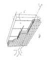
- FIG. 1is a perspective view of this invention with an anchoring system having a dovetail anchor and veneer tie inserted therein, as applied to a cavity wall with an inner wythe of masonry construction with insulation disposed on the cavity-side thereof and an outer wythe of brick;
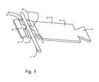
- FIG. 2is an enlarged perspective view of the anchoring system of FIG. 1 showing the veneer tie with a reinforcement wire set therein and secured within the anchor;
- FIG. 3is a perspective view of the veneer tie of FIG. 1 showing a reinforcement wire set therein;
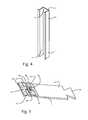
- FIG. 4is a perspective view of the dovetail anchor of FIG. 1 ;
- FIG. 5is a perspective view of an alternative veneer tie having a thermal coating on the insertion portion first end;
- FIG. 6is a perspective view of an alternative veneer tie having a thermal coating on the entire veneer tie.
- the inner wytheis optionally provided with insulation which is applied to the outer surface thereof.
- insulation integritymeans that, after the installation of the anchoring system, there is no change or interference with the insulative properties and concomitantly that there is substantially no change in the air and moisture infiltration characteristics.
- Anchoring systems for cavity wallsare used to secure veneer facings to buildings and overcome seismic and other forces, i.e. wind shear, etc, while ensuring insulation integrity.
- some systemshave experienced insulation tearing which results in the loss of insulation integrity.
- insulation integrityis preserved because the insulation is secured in a non-invasive manner.
- prior art sheetmetal anchorshave formed a conductive bridge between the wall cavity and the interior of the building.
- thermal conductivity and thermal conductivity analysisare used to examine this phenomenon and the metal-to-metal contacts across the inner wythe.
- the present anchoring systemserves to sever the conductive bridge and interrupt the thermal pathway created throughout the cavity wall by the metal components, including a reinforcement wire which provides a seismic structure. Failure to isolate the metal components of the anchoring system and break the thermal transfer results in heating and cooling losses and in potentially damaging condensation buildup within the cavity wall structure.
- the thermal stability within the cavity wallmaintains the internal temperature within a certain interval.
- the underlying metal veneer tieobtains a lower transmission (U-value) and thermal conductive value (K-value) providing a high-strength anchor with the benefits of thermal isolation.
- K-valueis used to describe the measure of heat conductivity of a particular material, i.e., the measure of the amount of heat, in BTUs per hour, that will be transmitted through one square foot of material that is one-inch thick to cause a temperature change of one degree Fahrenheit from one side of the material to the other.
- the lower the K-valuethe better the performance of the material as an insulator.
- the metal comprising the components of the anchoring systemsgenerally have a K-value range of 16 to 116 W/m K.
- the thermal coating disposed on the veneer tie of this inventiongreatly reduces such K-values to a low thermal conductive (K-value) not to exceed 1 W/m K (0.7 W/m K).
- K-valuelow thermal conductive
- U-valueis important to the thermal integrity of the cavity wall.
- the term U-valueis used to describe a measure of heat loss in a building component. It can also be referred to as an overall heat transfer co-efficient and measures how well parts of a building transfer heat. The higher the U-value, the worse the thermal performance of the building envelope.
- Low thermal transmission or U-valueis defined as not to exceed 0.35 W/m 2 K for walls.
- the U-valueis calculated from the reciprocal of the combined thermal resistances of the materials in the cavity wall, taking into account the effect of thermal bridges, air gaps and fixings.
- the first embodimentshows a dovetail anchoring system for use with a masonry inner wythe constructed of poured concrete.
- This anchoring systemdiscussed in detail hereinbelow, has a dovetail anchor and a sheetmetal veneer tie interconnected with a reinforcement wire.
- the anchoring system for cavity wallsis referred to generally by the numeral 10 .
- a cavity wall structure 12is shown having a masonry inner wythe or masonry backup 14 of poured concrete and an outer wythe or facing 18 of brick 20 or masonry block construction. Between the inner wythe 14 and the outer wythe 18 , a cavity 22 is formed. The cavity 22 has attached to the exterior surface 24 of the inner wythe 14 insulation 26 .
- the insulation 26 shownis rigid insulation, but is applicable to other forms including board insulation and spray-on insulation.
- an air/vapor barrier(not shown) is included between the insulation 26 and the exterior surface 24 of the inner wythe 14 .
- Successive bed joints 30 and 32are substantially planar and horizontally disposed and, in accord with current building standards, are 0.375-inch (approx.) in height. Selective ones of bed joints 30 and 32 , which are formed between courses of bricks 20 , are constructed to receive therewithin the insertion portion 50 of the veneer tie 44 .
- the cavity surface 24 of the inner wythe 14contains a horizontal line or x-axis 34 and intersecting vertical line or y-axis 36 .
- a horizontal line or z-axis 38normal to the xy-plane, passes through the coordinate origin formed by the intersecting x- and y-axes 34 , 36 .
- the dovetail anchor 40is secured within the inner wythe 14 and constructed from a sheetmetal body 41 having two major faces—the mounting surface 43 and the outer surface 45 .
- a dovetail slot 47is formed from the outer surface 45 of the dovetail anchor 40 and extends the length of the outer surface 45 .
- the dovetail anchor 40is a metal alloy constructed of material selected from a group consisting of mill galvanized steel, hot-dip galvanized steel, stainless steel, bright basic steel and similar.
- the dovetail anchor 40is secured within the poured concrete inner wythe 14 .
- the veneer tie 44is constructed from sheet metal and is a single construct.
- the veneer tie 44includes an insertion portion 50 having a first end 52 for securement within the outer wythe 18 bed joint 32 and is adjustably mounted within the dovetail slot 47 of the dovetail anchor 40 .
- the veneer tie 44includes an insertion portion 50 having a first end 52 and is shown in FIGS. 1 and 2 as being emplaced on a course of bricks 20 in preparation for embedment in the mortar of bed joint 32 , and a second end 54 which lies within the cavity 22 .
- the veneer tie 44 interconnecting portion 56is contiguous with the second end 54 and adjustably mounted within the dovetail slot 47 .
- a seismic notch 58is formed from the insertion portion first end 52 and is dimensioned for a snap-fit relationship with a reinforcement wire or outer wythe reinforcement 71 , however, the anchoring system 10 is optionally employed without a reinforcement wire 71 .
- the seismic notch 58includes two securement tabs 60 and a securement depression 62 , contiguous with each of the two securement tabs 60 forming a seat 64 to accommodate the reinforcement wire 71 .
- the use of a reinforcement wire 71forms a seismic construct.
- the veneer tie 44is a metal alloy constructed of mill galvanized steel, hot-dip galvanized steel, stainless steel, bright basic steel or similar.
- a thermally-isolating coating or thermal coating 85is applied to the insertion portion first end 52 of the veneer tie 44 to provide a thermal break in the cavity 22 , restricting thermal transfer between the veneer tie 44 and the wall anchor 40 and between the wall anchor 40 and the veneer tie 44 .
- the thermal coating 85is optionally applied to the insertion portion second end 54 and the interconnecting portion 56 to provide ease of coating and additional thermal protection.
- the thermal coating 85is selected from thermoplastics, thermosets, natural fibers, rubbers, resins, asphalts, ethylene propylene diene monomers, and admixtures thereof and applied in layers.
- the thermal coating 85optionally contains an isotropic polymer which includes, but is not limited to, acrylics, nylons, epoxies, silicones, polyesters, polyvinyl chlorides, and chlorosulfonated polyethelenes.
- the thermal coating 85is applied in layers including an initial layer or prime coat 87 of the thermal coating 85 which is cured to provide a precoat and the layers of the thermal coating 85 are cross-linked to provide high-strength adhesion to the veneer tie to resist chipping or wearing of the thermal coating 85 .
- the thermal coating 85reduces the K-value and the U-value of the underlying metal components which have K-values that range from 16 to 116 W/m K.
- the thermal coating 85reduces the K-value of the veneer tie 44 to not exceed 1.0 W/m K and the associated U-value to not exceed 0.35 W/m 2 K.
- the thermal coating 85is not combustible and gives off no toxic smoke in the event of a fire. Additionally, the thermal coating 85 provides corrosion protection which protects against deterioration of the anchoring system 10 over time.
- the thermal coating 85is applied through any number of methods including fluidized bed production, thermal spraying, hot dip processing, heat-assisted fluid coating, or extrusion, and includes both powder and fluid coating to form a reasonably uniform coating.
- a coating 85 having a thickness of at least about 5 micrometersis optimally applied.
- the thermal coating 85is applied in layers in a manner that provides strong adhesion to the veneer tie 44 .
- the thermal coating 85is cured to achieve good cross-linking of the layers and has a matte finish 89 to securely hold to the bed joint 32 and increase the strength and pullout resistance of the veneer tie 44 .
- Appropriate examples of the nature of the coating and application processare set forth in U.S. Pat. Nos. 6,284,311 and 6,612,343.
- the present inventionserves to thermally isolate the components of the anchoring system, reducing the thermal transmission and conductivity values of the anchoring system to low levels.
- the novel coatingprovides an insulating effect that is high-strength and provides an in-cavity thermal break, severing the thermal threads created from the interlocking anchoring system components.
- the single construct veneer tieserves as a high-strength interconnecting component and includes a seismic interconnection.
Landscapes
- Engineering & Computer Science (AREA)
- Architecture (AREA)
- Physics & Mathematics (AREA)
- Electromagnetism (AREA)
- Civil Engineering (AREA)
- Structural Engineering (AREA)
- Acoustics & Sound (AREA)
- Environmental & Geological Engineering (AREA)
- Building Environments (AREA)
Abstract
Description
| Pat. | Inventor | Issue Date | ||
| 4,373,314 | Allan | Feb. 15, 1983 | ||
| 4,869,038 | Catani | Sep. 26, 1989 | ||
| 5,063,722 | Hohmann | Nov. 12, 1991 | ||
| 5,392,581 | Hatzinikolas, et al. | Feb. 28, 1995 | ||
| 5,456,052 | Anderson et al. | Oct. 10, 1995 | ||
| 5,671,578 | Hohmann | Sep. 30, 1997 | ||
| 6,125,608 | Charlson | Oct. 3, 2000 | ||
| 7,325,366 | Hohmann, Jr., et al. | Feb. 5, 2008 | ||
| 8,109,706 | Richards | Feb. 7, 2012 | ||
| 8,122,663 | Hohmann, Jr., et al. | Feb. 28, 2012 | ||
Claims (18)
Priority Applications (2)
| Application Number | Priority Date | Filing Date | Title |
|---|---|---|---|
| US14/046,556US9038350B2 (en) | 2013-10-04 | 2013-10-04 | One-piece dovetail veneer tie and wall anchoring system with in-cavity thermal breaks |
| CA2865857ACA2865857C (en) | 2013-10-04 | 2014-10-03 | One-piece dovetail veneer tie and wall anchoring system with in-cavity thermal breaks |
Applications Claiming Priority (1)
| Application Number | Priority Date | Filing Date | Title |
|---|---|---|---|
| US14/046,556US9038350B2 (en) | 2013-10-04 | 2013-10-04 | One-piece dovetail veneer tie and wall anchoring system with in-cavity thermal breaks |
Publications (2)
| Publication Number | Publication Date |
|---|---|
| US20150096243A1 US20150096243A1 (en) | 2015-04-09 |
| US9038350B2true US9038350B2 (en) | 2015-05-26 |
Family
ID=52775814
Family Applications (1)
| Application Number | Title | Priority Date | Filing Date |
|---|---|---|---|
| US14/046,556Expired - Fee RelatedUS9038350B2 (en) | 2013-10-04 | 2013-10-04 | One-piece dovetail veneer tie and wall anchoring system with in-cavity thermal breaks |
Country Status (2)
| Country | Link |
|---|---|
| US (1) | US9038350B2 (en) |
| CA (1) | CA2865857C (en) |
Cited By (4)
| Publication number | Priority date | Publication date | Assignee | Title |
|---|---|---|---|---|
| US10927552B2 (en) | 2019-02-15 | 2021-02-23 | Stone Creek Products, LLC | Veneer panel and veneer corner with mounting systems |
| US10954667B2 (en) | 2018-09-27 | 2021-03-23 | Columbia Insurance Company | Adjustable masonry anchor |
| US20220018116A1 (en)* | 2020-07-15 | 2022-01-20 | Columbia Insurance Company | Facade support system |
| US11248374B2 (en) | 2019-06-26 | 2022-02-15 | Columbia Insurance Company | Facade support system |
Families Citing this family (10)
| Publication number | Priority date | Publication date | Assignee | Title |
|---|---|---|---|---|
| US8800241B2 (en) | 2012-03-21 | 2014-08-12 | Mitek Holdings, Inc. | Backup wall reinforcement with T-type anchor |
| US9038351B2 (en) | 2013-03-06 | 2015-05-26 | Columbia Insurance Company | Thermally coated wall anchor and anchoring systems with in-cavity thermal breaks for cavity walls |
| US9140001B1 (en) | 2014-06-24 | 2015-09-22 | Columbia Insurance Company | Thermal wall anchor |
| US9273461B1 (en) | 2015-02-23 | 2016-03-01 | Columbia Insurance Company | Thermal veneer tie and anchoring system |
| US10407892B2 (en) | 2015-09-17 | 2019-09-10 | Columbia Insurance Company | High-strength partition top anchor and anchoring system utilizing the same |
| USD846973S1 (en) | 2015-09-17 | 2019-04-30 | Columbia Insurance Company | High-strength partition top anchor |
| US20170159285A1 (en) | 2015-12-04 | 2017-06-08 | Columbia Insurance Company | Thermal wall anchor |
| US11401709B2 (en)* | 2017-10-31 | 2022-08-02 | Simpson Strong-Tie Company Inc. | Brick tie gap connector |
| CN111593819A (en)* | 2020-06-30 | 2020-08-28 | 浙江大学建筑设计研究院有限公司 | Pre-embedded masonry wall connecting assembly capable of being adjusted flexibly and positioned accurately and using method |
| KR102209349B1 (en)* | 2020-07-02 | 2021-01-28 | 길태식 | Movable anchor apparatus for constructing masonry wall |
Citations (187)
| Publication number | Priority date | Publication date | Assignee | Title |
|---|---|---|---|---|
| US819869A (en) | 1905-05-03 | 1906-05-08 | Joseph F Dunlap | Wall-tie. |
| US903000A (en) | 1906-01-12 | 1908-11-03 | Stephen Priest Jr | Wall-tie. |
| US1014157A (en)* | 1911-07-12 | 1912-01-09 | Henry L Lewen | Floor and ceiling construction. |
| US1170419A (en) | 1913-12-29 | 1916-02-01 | Arthur B Coon | Building construction. |
| USRE15979E (en)* | 1925-01-06 | Construction tie | ||
| US1794684A (en) | 1929-04-23 | 1931-03-03 | Charles E Handel | Anchor for veneered concrete structures |
| US1936223A (en)* | 1930-05-12 | 1933-11-21 | Floor Accessories Company Inc | Wall tie |
| US2058148A (en) | 1934-02-26 | 1936-10-20 | Merrill W Hard | Tile supporting strip |
| US2097821A (en) | 1935-04-15 | 1937-11-02 | Horace C Mathers | Masonry |
| US2280647A (en) | 1940-12-16 | 1942-04-21 | Harold B Hawes | Structural curb or wall |
| US2300181A (en) | 1940-07-05 | 1942-10-27 | Harold L Spaight | Means for constructing buildings |
| US2403566A (en) | 1944-03-24 | 1946-07-09 | Fulton Co | Lock nut |
| US2413772A (en) | 1943-01-15 | 1947-01-07 | Adel Prec Products Corp | Clip for multiple conduit supports |
| CH279209A (en) | 1949-11-24 | 1951-11-30 | Desplantes Pierre | Part for fixing a piece of joinery to a hollow brick wall. |
| US2605867A (en) | 1947-05-10 | 1952-08-05 | George I Goodwin | Structural member |
| US2780936A (en) | 1951-01-29 | 1957-02-12 | Superior Concrete Accessories | Channel shaped anchor retaining strip for embedment in concrete |
| US2898758A (en)* | 1955-09-28 | 1959-08-11 | Gateway Engineering Company | Anchor slot channel structure |
| US2929238A (en) | 1957-04-23 | 1960-03-22 | Karl H Kaye | Masonry joint mesh strip |
| US2966705A (en) | 1954-04-30 | 1961-01-03 | Massey William | Invisible means for attaching panels to walls and the like |
| US2999571A (en) | 1958-09-12 | 1961-09-12 | Peter H Huber | Powder-actuated fastener |
| US3030670A (en) | 1958-07-15 | 1962-04-24 | Donald W Bigelow | Ceiling construction |
| US3183628A (en) | 1962-10-12 | 1965-05-18 | Lox All Sales Corp | Masonry wall reinforcing means |
| US3254736A (en) | 1963-10-24 | 1966-06-07 | Perfect Parts Inc | Automotive battery securing device |
| US3277626A (en) | 1963-10-17 | 1966-10-11 | Dur O Wal National Inc | Double shank adjustable wall tie |
| US3300939A (en) | 1963-10-17 | 1967-01-31 | Dur O Wal National Inc | Combination adjustable tie and joint reinforcement for wall constructions |
| US3309828A (en) | 1963-02-04 | 1967-03-21 | Charles J Tribble | Tie assembly for faced masonry wall structures |
| US3310926A (en) | 1964-04-08 | 1967-03-28 | Air Entpr Inc | Panel construction |
| US3341998A (en) | 1965-04-23 | 1967-09-19 | Aa Wire Products Co | Flexible reinforcement joint for masonry wall reinforcement |
| US3377764A (en) | 1966-04-26 | 1968-04-16 | Storch Bernard | Anchoring means for masonry walls |
| US3478480A (en) | 1968-06-17 | 1969-11-18 | William E Swenson | Thin stone supporting and anchoring system |
| US3563131A (en) | 1969-04-23 | 1971-02-16 | Lockheed Aircraft Corp | Spacer |
| US3568389A (en) | 1968-11-05 | 1971-03-09 | Aa Wire Prod Co | Anchorage and reinforcement device for masonry walls |
| US3640043A (en) | 1969-06-30 | 1972-02-08 | Langensiepen Kg M | Wall facing |
| US3964226A (en) | 1974-09-27 | 1976-06-22 | Hohmann & Barnard, Inc. | Adjustable wall-tie reinforcing system |
| US3964227A (en) | 1974-09-27 | 1976-06-22 | Hohmann & Barnard, Inc. | Anchoring apparatus for fixedly spacing multiple wall constructions |
| US4021990A (en) | 1976-01-27 | 1977-05-10 | Hohmann & Barnard, Inc. | Veneer anchor and dry wall construction system and method |
| GB1575501A (en) | 1976-11-05 | 1980-09-24 | Ellidge A | Tie means for brick walls |
| US4227359A (en) | 1978-11-21 | 1980-10-14 | National Wire Products | Adjustable single unit masonry reinforcement |
| US4238987A (en) | 1977-08-31 | 1980-12-16 | Hilti Aktiengesellschaft | Expansion dowel for spaced mounting of parts on a support structure |
| GB2069024A (en) | 1979-12-19 | 1981-08-19 | Ws Stainless Fixings Sheffield | Lateral restraint fixing for building work |
| US4305239A (en) | 1979-03-15 | 1981-12-15 | Geraghty Robin C | Device for use in building |
| US4373314A (en) | 1981-12-10 | 1983-02-15 | Aa Wire Products Company | Masonry veneer wall anchor |
| US4382416A (en) | 1981-02-17 | 1983-05-10 | Kellogg Smith Ogden | Detachable nestable mast steps |
| US4424745A (en) | 1972-03-24 | 1984-01-10 | The United States Of America As Represented By The Secretary Of The Navy | Digital timer fuze |
| US4438611A (en) | 1982-03-31 | 1984-03-27 | W. R. Grace & Co. | Stud fasteners and wall structures employing same |
| US4473984A (en) | 1983-09-13 | 1984-10-02 | Lopez Donald A | Curtain-wall masonry-veneer anchor system |
| US4482368A (en) | 1983-02-28 | 1984-11-13 | Nelson Industries, Inc. | Air cleaning assembly including a fastening assembly having a novel wing nut construction |
| US4571909A (en) | 1984-09-07 | 1986-02-25 | Keller Structures, Inc. | Insulated building and method of manufacturing same |
| US4596102A (en) | 1984-01-12 | 1986-06-24 | Dur-O-Wal, Inc. | Anchor for masonry veneer |
| US4598518A (en) | 1984-11-01 | 1986-07-08 | Hohmann Enterprises, Inc. | Pronged veneer anchor and dry wall construction system |
| US4606163A (en) | 1985-09-09 | 1986-08-19 | Dur-O-Wal, Inc. | Apertured channel veneer anchor |
| US4622796A (en)* | 1981-12-30 | 1986-11-18 | Aziz Edward M | Structural connection for cavity wall construction |
| US4628657A (en) | 1984-05-16 | 1986-12-16 | Krupp Polysius Ag | Ceiling and wall construction |
| US4636125A (en) | 1984-11-29 | 1987-01-13 | Burgard Francis A | Mounting device and method of use |
| US4640848A (en) | 1985-08-26 | 1987-02-03 | Kennecott Corporation | Spray-applied ceramic fiber insulation |
| US4660342A (en) | 1985-10-04 | 1987-04-28 | Jeffery Salisbury | Anchor for mortarless block wall system |
| US4703604A (en) | 1985-06-07 | 1987-11-03 | Robert Muller | Externally insulated and sheathed masonry construction |
| US4708551A (en) | 1984-01-09 | 1987-11-24 | Hilti Aktiengesellschaft | Expansion dowel assembly |
| US4738070A (en) | 1986-11-24 | 1988-04-19 | Abbott Gary W | Masonry wall tie unit |
| US4764069A (en) | 1987-03-16 | 1988-08-16 | Elco Industries, Inc. | Anchor for masonry veneer walls |
| US4819401A (en) | 1988-04-08 | 1989-04-11 | Whitney Jr G Ward | Wire anchor for metal stud/brick veneer wall construction |
| US4827684A (en) | 1988-03-17 | 1989-05-09 | Aa Wire Products Company | Masonry veneer wall anchor |
| US4843776A (en) | 1988-07-19 | 1989-07-04 | Alvin Guignard | Brick tie |
| US4852320A (en) | 1988-04-19 | 1989-08-01 | Ballantyne Brian R | Mortar collecting device for use in masonry wall construction |
| US4869043A (en) | 1988-08-02 | 1989-09-26 | Fero Holdings Ltd. | Shear connector |
| US4869038A (en) | 1987-10-19 | 1989-09-26 | Dur-O-Wall Inc. | Veneer wall anchor system |
| US4875319A (en) | 1988-06-13 | 1989-10-24 | Hohmann & Barnard, Inc. | Seismic construction system |
| US4911949A (en) | 1986-08-27 | 1990-03-27 | Toyota Jidosha Kabushiki Kaisha | Method for coating metal part with synthetic resin including post coating step for heating coated part to eleminate voids |
| US4922680A (en) | 1989-01-09 | 1990-05-08 | Mkh3 Enterprises, Inc. | Systems and methods for connecting masonry veneer to structural support substrates |
| US4946632A (en) | 1987-05-27 | 1990-08-07 | Pollina Peter J | Method of constructing a masonry structure |
| US4955172A (en) | 1989-09-14 | 1990-09-11 | Pierson Neil W | Veneer anchor |
| US5063722A (en) | 1989-03-31 | 1991-11-12 | Hohmann Enterprises, Inc. | Gripstay channel veneer anchor assembly |
| GB2246149A (en) | 1990-07-17 | 1992-01-22 | Ancon Stainless Steel Fixings | Structural post for wall ties |
| US5099628A (en) | 1989-11-27 | 1992-03-31 | Stt, Inc. | Apparatus for enhancing structural integrity of masonry structures |
| US5207043A (en) | 1988-11-07 | 1993-05-04 | Mcgee Brian P | Masonry connector |
| GB2265164A (en) | 1992-03-13 | 1993-09-22 | Harris & Edgar Limited | A windpost,a windpost assembly and a method of tying two spaced members therewith |
| US5307602A (en) | 1989-09-08 | 1994-05-03 | Richard Lebraut | Settable fitting allowing the fixation of facade lining outer panel boards |
| US5392581A (en) | 1993-11-08 | 1995-02-28 | Fero Holdings Ltd. | Masonry connector |
| EP0199595B1 (en) | 1985-04-23 | 1995-03-22 | The Expanded Metal Company Limited | Wall construction device |
| US5408798A (en) | 1993-11-04 | 1995-04-25 | Hohmann; Ronald P. | Seismic construction system |
| US5440854A (en) | 1989-08-28 | 1995-08-15 | Hohmann Enterprises, Inc. | Veneer structural assembly and drywall construction system |
| US5454200A (en) | 1993-11-04 | 1995-10-03 | Hohmann; Ronald P. | Veneer anchoring system |
| US5456052A (en) | 1991-05-27 | 1995-10-10 | Abey Australia Pty. Ltd. | Two-part masonry tie |
| US5490366A (en) | 1994-11-24 | 1996-02-13 | Burns; William S. | Adjustable wall tie |
| US5598673A (en) | 1994-01-18 | 1997-02-04 | Atkins; Mark R. | Masonry cavity wall air space and weeps obstruction prevention system |
| US5634310A (en) | 1993-11-04 | 1997-06-03 | Hohmann & Barnard, Inc. | Surface-mounted veneer anchor |
| US5669592A (en) | 1995-09-26 | 1997-09-23 | Kearful; Robert G. | Camera support |
| US5671578A (en) | 1995-04-24 | 1997-09-30 | Hohmann & Barnard, Inc. | Surface-mounted veneer anchor for seismic construction system |
| US5673527A (en) | 1995-09-05 | 1997-10-07 | Zampell Advanced Refractory Technologies, Inc. | Refractory tile, mounting device, and method for mounting |
| US5816008A (en) | 1997-06-02 | 1998-10-06 | Hohmann & Barnard, Inc. | T-head, brick veneer anchor |
| US5819486A (en) | 1995-10-31 | 1998-10-13 | 1140595 Ontario, Inc. | Apparatus and method of installation of a composite building panel |
| US5845455A (en) | 1998-01-12 | 1998-12-08 | Masonry Reinforcing Corporation Of America | Mortar collecting device for protecting weep-holes in masonry walls |
| US6000178A (en) | 1995-10-31 | 1999-12-14 | Goodings; Peter J. | Apparatus and method of installation of a composite building panel |
| US6125608A (en) | 1997-04-07 | 2000-10-03 | United States Building Technology, Inc. | Composite insulated framing members and envelope extension system for buildings |
| US6209281B1 (en) | 1998-01-30 | 2001-04-03 | Bailey Metal Products Limited | Brick tie anchor |
| US6279283B1 (en) | 2000-04-12 | 2001-08-28 | Hohmann & Barnard, Inc. | Low-profile wall tie |
| US6284311B1 (en) | 1996-04-08 | 2001-09-04 | E. I. Du Pont De Nemours And Company | Process for applying polymer particles on substrate and coatings resulting therefrom |
| US6332300B1 (en) | 1999-01-08 | 2001-12-25 | Wakai & Co., Ltd. | Double wall coupling tool |
| US20010054270A1 (en) | 1998-01-30 | 2001-12-27 | John Rice | Brick tie anchor |
| US6351922B1 (en) | 2000-11-20 | 2002-03-05 | Blok-Lok Limited | Single-end wall tie |
| US6367219B1 (en) | 1998-05-07 | 2002-04-09 | New Market Developments Ltd. | Building cavity assembly |
| US20020100239A1 (en) | 2000-12-01 | 2002-08-01 | Heckmann Building Products, Inc. And Dl Enterprises, Inc. | Wire tie and hardware system |
| US20030121226A1 (en) | 2001-07-25 | 2003-07-03 | Manuel Bolduc | Method for installing wood flooring |
| US6612343B2 (en) | 1998-01-22 | 2003-09-02 | Institut Francais Du Petrole | Use of polymer compositions for coating surfaces, and surface coatings comprising such compositions |
| US6627128B1 (en) | 1998-11-19 | 2003-09-30 | Centria | Composite joinery |
| US20030217521A1 (en) | 2002-05-24 | 2003-11-27 | Richard B. Richardson | Adjustable anchoring system for a wall |
| US6668505B1 (en) | 2002-09-03 | 2003-12-30 | Hohmann & Barnard, Inc. | High-span anchors and reinforcements for masonry walls |
| US6686301B2 (en) | 1998-03-09 | 2004-02-03 | Shulong Li | High peel strength rubber/textile composites |
| US20040083667A1 (en) | 2002-11-06 | 2004-05-06 | Johnson Ralph O | Masonry anchoring system |
| US6739105B2 (en) | 2000-12-22 | 2004-05-25 | Biomedy Limited | Constructional elements |
| US6789365B1 (en) | 2002-11-13 | 2004-09-14 | Hohmann & Barnard, Inc. | Side-welded anchors and reinforcements for masonry walls |
| US20040216413A1 (en) | 2003-05-01 | 2004-11-04 | Hohmann & Barnard, Inc. | Wall anchor constructs and surface-mounted anchoring systems utilizing the same |
| US20040216408A1 (en) | 2003-04-30 | 2004-11-04 | Hohmann & Barnard, Inc. | High-strength surface-mounted anchors and wall anchor systems using the same |
| US6817147B1 (en) | 1999-12-30 | 2004-11-16 | Steelcase Development Corporation | Clip for panel trim |
| US20040231270A1 (en) | 2003-05-22 | 2004-11-25 | Collins P. Michael | Masonry tie for cavity wall construction |
| US6827969B1 (en) | 2003-12-12 | 2004-12-07 | General Electric Company | Field repairable high temperature smooth wear coating |
| US6837013B2 (en) | 2002-10-08 | 2005-01-04 | Joel Foderberg | Lightweight precast concrete wall panel system |
| US6851239B1 (en) | 2002-11-20 | 2005-02-08 | Hohmann & Barnard, Inc. | True-joint anchoring systems for cavity walls |
| US20050279043A1 (en) | 2004-06-18 | 2005-12-22 | Joseph Bronner | Wall anchor system and method |
| US7007433B2 (en) | 2003-01-14 | 2006-03-07 | Centria | Features for thin composite architectural panels |
| US7017318B1 (en) | 2002-07-03 | 2006-03-28 | Hohmann & Barnard, Inc. | High-span anchoring system for cavity walls |
| US7043884B2 (en) | 2002-02-14 | 2006-05-16 | Eurogramco,S. L. | Cladding system |
| US7059577B1 (en) | 2001-11-30 | 2006-06-13 | Ferrall Burgett | Insulated concrete wall system and method of making same |
| USD527834S1 (en) | 2004-04-20 | 2006-09-05 | Centria | Building panel |
| US20060198717A1 (en) | 2002-10-31 | 2006-09-07 | Benjamin Fuest | Device for fixing an object to a tree |
| US20060242921A1 (en) | 2005-04-14 | 2006-11-02 | Massie Michael C | Masonry cavity wall construction and method of making same |
| US20060251916A1 (en) | 2004-09-28 | 2006-11-09 | Hideyuki Arikawa | High temperature component with thermal barrier coating and gas turbine using the same |
| US7147419B2 (en) | 2004-06-23 | 2006-12-12 | Savio S.P.A. | Element of fastening accessories to metal windows and doors |
| US20070011964A1 (en)* | 2005-07-12 | 2007-01-18 | Earl Smith | Composite wall tie system and method |
| US7171788B2 (en) | 2002-04-05 | 2007-02-06 | Joseph Bronner | Masonry connectors and twist-on hook and method |
| US7178299B2 (en) | 2003-05-16 | 2007-02-20 | Exxonmobil Research And Engineering Company | Tiles with embedded locating rods for erosion resistant linings |
| US7225590B1 (en) | 2003-07-14 | 2007-06-05 | The Steel Network, Inc. | Brick tie |
| US7325366B1 (en) | 2005-08-08 | 2008-02-05 | Hohmann & Barnard, Inc. | Snap-in wire tie |
| US7334374B2 (en) | 2001-08-03 | 2008-02-26 | Schmid Ben L | Stucco sheathing fastener |
| US20080092472A1 (en) | 2006-10-18 | 2008-04-24 | Reward Wall Systems, Inc. | Adjustable masonry anchor assembly for use with insulating concrete form systems |
| US7374825B2 (en) | 2004-12-01 | 2008-05-20 | General Electric Company | Protection of thermal barrier coating by an impermeable barrier coating |
| US20080141605A1 (en) | 2006-12-14 | 2008-06-19 | Hohmann & Barnard, Inc. | Dual seal anchoring systems for insulated cavity walls |
| US20080222992A1 (en) | 2007-03-15 | 2008-09-18 | Nichiha Corporation | Backing metal fixture and external wall constructing structure using the same |
| US7469511B2 (en)* | 2004-02-06 | 2008-12-30 | The Eci Group, Llc | Masonry anchoring system |
| US7481032B2 (en) | 2004-04-22 | 2009-01-27 | Neil Tarr | Stud system for insulation of concrete structures |
| US20090133351A1 (en) | 2005-09-21 | 2009-05-28 | The Eci Group, Llc | Veneer anchoring system |
| US20090133357A1 (en) | 2007-11-28 | 2009-05-28 | Richards Joseph P | Composite fastener, belly nut, tie system and/or method for reducing heat transfer through a building envelope |
| US7562506B2 (en) | 2003-04-30 | 2009-07-21 | Mitek Holdings, Inc. | Notched surface-mounted anchors and wall anchor systems using the same |
| US20100037552A1 (en) | 2008-08-13 | 2010-02-18 | Joseph Bronner | Side mounted drill bolt and threaded anchor system for veneer wall tie connection |
| US20100101175A1 (en) | 2008-10-27 | 2010-04-29 | Mitek Holdings, Inc. | Locking concrete insert |
| US7748181B1 (en) | 2006-01-20 | 2010-07-06 | Centria | Advanced building envelope delivery system and method |
| US20100192495A1 (en) | 2005-12-19 | 2010-08-05 | Shouldice Designer Stone Ltd. | Thin stone or brick veneer wall system and clips therefor |
| US7788869B2 (en) | 2003-11-13 | 2010-09-07 | Extech/Exterior Technologies, Inc. | Slidable panel clip assembly for use with roof or wall panels |
| US20100257803A1 (en) | 2009-04-10 | 2010-10-14 | Mitek Holdings, Inc. | Wind load anchors and high-wind anchoring systems for cavity walls |
| USD626817S1 (en) | 2008-01-07 | 2010-11-09 | Chatsworth Products, Inc. | Accessory bracket for fiber management |
| US20110023748A1 (en) | 2009-02-23 | 2011-02-03 | Wagh Arun S | Fire protection compositions, methods, and articles |
| US20110041442A1 (en) | 2009-08-23 | 2011-02-24 | Thuan Bui | Fastener for lightweight concrete panel and panel assembly |
| US20110047919A1 (en) | 2009-09-03 | 2011-03-03 | Mitek Holdings, Inc. | Thermally isolated anchoring system |
| US20110061333A1 (en) | 2009-09-11 | 2011-03-17 | Joseph Bronner | Twist On Wire Tie Wall Connection System And Method |
| US20110083389A1 (en) | 2009-10-14 | 2011-04-14 | Thuan Bui | Fastener for lightweight concrete panel and panel assembly |
| US20110146195A1 (en) | 2009-12-17 | 2011-06-23 | Mitek Holdings, Inc. | Rubble stone anchoring system |
| US20110173902A1 (en) | 2010-01-15 | 2011-07-21 | Mitek Holdings, Inc. | Anchor System for Composite Panel |
| US8051619B2 (en) | 2008-10-27 | 2011-11-08 | Mitek Holdings, Inc. | Reinforcing spacer device |
| US20110277397A1 (en) | 2010-05-11 | 2011-11-17 | Mitek Holdings, Inc. | Restoration Anchoring System |
| US8122663B1 (en) | 2004-09-10 | 2012-02-28 | Mitek Holdings, Inc. | Anchors and reinforcements for masonry walls |
| US8209934B2 (en) | 2009-02-20 | 2012-07-03 | Alan Pettingale | Wall tie and method of using and making same |
| US8215083B2 (en) | 2004-07-26 | 2012-07-10 | Certainteed Corporation | Insulation board with air/rain barrier covering and water-repellent covering |
| US20120186183A1 (en) | 2011-01-21 | 2012-07-26 | Masonry Reinforcing Corporation Of America | Wall anchoring device and method |
| US20120285111A1 (en)* | 2011-05-11 | 2012-11-15 | Masonry Reinforcing Corporation Of America | Masonry wall anchor and seismic wall anchoring system |
| US20120304576A1 (en) | 2011-05-31 | 2012-12-06 | Mitek Holdings, Inc. | Dual seal tubular anchor for cavity walls |
| US20120308330A1 (en) | 2011-06-02 | 2012-12-06 | Mitek Holdings, Inc. | Thermally isolating tubule for wall anchor |
| US20130008121A1 (en) | 2011-07-08 | 2013-01-10 | Plexus Innovations Inc. | Multi-piece anchor system for use with masonry over stud back-up walls |
| GB2459936B (en) | 2008-05-16 | 2013-03-27 | Victor Joseph Wigley | Improvements to insulation, airtightness and service provision in masonary walls |
| US20130074435A1 (en) | 2011-09-23 | 2013-03-28 | Mitek Holdings, Inc. | Dual pintle and anchoring system utilizing the same |
| US8511041B2 (en) | 2009-03-26 | 2013-08-20 | Profileset B.V. | Assembly for the temporary attachment of a vertical masonry guide to the inner leaf of a cavity wall |
| US20130232893A1 (en) | 2012-03-08 | 2013-09-12 | Mitek Holdings, Inc. | Backup wall reinforcement with t-type siderail |
| US20130232909A1 (en) | 2012-02-23 | 2013-09-12 | Heckmann Building Products Inc. | Thermal clip attachment apparatus for masonry anchors and methods thereof |
| US20130247482A1 (en) | 2012-03-21 | 2013-09-26 | Mitek Holdings, Inc. | High-strength partially compressed veneer ties and anchoring systems utilizing the same |
| US20130247498A1 (en) | 2012-03-21 | 2013-09-26 | Mitek Holdings, Inc. | L-shaped sheetmetal anchor with tubular leg and anchoring assembly |
| US20130247483A1 (en) | 2012-03-21 | 2013-09-26 | Mitek Holdings, Inc. | Thermally-isolated anchoring systems for cavity walls |
| US20130247484A1 (en) | 2012-03-21 | 2013-09-26 | Mitek Holdings, Inc. | Backup wall reinforcement with t-type anchor |
| US8544228B2 (en) | 2009-10-27 | 2013-10-01 | Joseph Bronner | Winged anchor and spiked spacer for veneer wall tie connection system and method |
| US8596010B2 (en) | 2011-05-20 | 2013-12-03 | Mitek Holdings, Inc. | Anchor with angular adjustment |
| US8613175B2 (en) | 2011-09-23 | 2013-12-24 | Mitek Holdings, Inc. | High-strength pintles and anchoring systems utilizing the same |
| US20130340378A1 (en) | 2012-06-22 | 2013-12-26 | Mitek Holdings, Inc. | Anchor with angular adjustment |
| US20140000211A1 (en) | 2012-06-28 | 2014-01-02 | Mitek Holdings, Inc. | Low profile pullout resistant pintle and anchoring system utilizing the same |
| US8667757B1 (en) | 2013-03-11 | 2014-03-11 | Mitek Holdings, Inc. | Veneer tie and wall anchoring systems with in-cavity thermal breaks |
| US20140075856A1 (en) | 2012-09-15 | 2014-03-20 | Mitek Holdings, Inc. | Pullout resistant pintle and anchoring system utilizing the same |
| US20140075855A1 (en) | 2012-09-15 | 2014-03-20 | Mitek Holdings, Inc. | High-strength veneer tie and thermally isolated anchoring systems utilizing the same |
| US20140075879A1 (en) | 2012-09-15 | 2014-03-20 | Mitek Holdings, Inc. | High-strength partially compressed low profile veneer tie and anchoring system utilizing the same |
| US20140096466A1 (en) | 2012-03-14 | 2014-04-10 | Mitek Holdings, Inc. | Mounting Arrangement for Panel Veneer Structures |
| US20140174013A1 (en) | 2012-12-26 | 2014-06-26 | Mitek Holdings, Inc. | High-strength ribbon loop anchors and anchoring systems utilizing the same |
- 2013
- 2013-10-04USUS14/046,556patent/US9038350B2/ennot_activeExpired - Fee Related
- 2014
- 2014-10-03CACA2865857Apatent/CA2865857C/ennot_activeExpired - Fee Related
Patent Citations (214)
| Publication number | Priority date | Publication date | Assignee | Title |
|---|---|---|---|---|
| USRE15979E (en)* | 1925-01-06 | Construction tie | ||
| US819869A (en) | 1905-05-03 | 1906-05-08 | Joseph F Dunlap | Wall-tie. |
| US903000A (en) | 1906-01-12 | 1908-11-03 | Stephen Priest Jr | Wall-tie. |
| US1014157A (en)* | 1911-07-12 | 1912-01-09 | Henry L Lewen | Floor and ceiling construction. |
| US1170419A (en) | 1913-12-29 | 1916-02-01 | Arthur B Coon | Building construction. |
| US1794684A (en) | 1929-04-23 | 1931-03-03 | Charles E Handel | Anchor for veneered concrete structures |
| US1936223A (en)* | 1930-05-12 | 1933-11-21 | Floor Accessories Company Inc | Wall tie |
| US2058148A (en) | 1934-02-26 | 1936-10-20 | Merrill W Hard | Tile supporting strip |
| US2097821A (en) | 1935-04-15 | 1937-11-02 | Horace C Mathers | Masonry |
| US2300181A (en) | 1940-07-05 | 1942-10-27 | Harold L Spaight | Means for constructing buildings |
| US2280647A (en) | 1940-12-16 | 1942-04-21 | Harold B Hawes | Structural curb or wall |
| US2413772A (en) | 1943-01-15 | 1947-01-07 | Adel Prec Products Corp | Clip for multiple conduit supports |
| US2403566A (en) | 1944-03-24 | 1946-07-09 | Fulton Co | Lock nut |
| US2605867A (en) | 1947-05-10 | 1952-08-05 | George I Goodwin | Structural member |
| CH279209A (en) | 1949-11-24 | 1951-11-30 | Desplantes Pierre | Part for fixing a piece of joinery to a hollow brick wall. |
| US2780936A (en) | 1951-01-29 | 1957-02-12 | Superior Concrete Accessories | Channel shaped anchor retaining strip for embedment in concrete |
| US2966705A (en) | 1954-04-30 | 1961-01-03 | Massey William | Invisible means for attaching panels to walls and the like |
| US2898758A (en)* | 1955-09-28 | 1959-08-11 | Gateway Engineering Company | Anchor slot channel structure |
| US2929238A (en) | 1957-04-23 | 1960-03-22 | Karl H Kaye | Masonry joint mesh strip |
| US3030670A (en) | 1958-07-15 | 1962-04-24 | Donald W Bigelow | Ceiling construction |
| US2999571A (en) | 1958-09-12 | 1961-09-12 | Peter H Huber | Powder-actuated fastener |
| US3183628A (en) | 1962-10-12 | 1965-05-18 | Lox All Sales Corp | Masonry wall reinforcing means |
| US3309828A (en) | 1963-02-04 | 1967-03-21 | Charles J Tribble | Tie assembly for faced masonry wall structures |
| US3277626A (en) | 1963-10-17 | 1966-10-11 | Dur O Wal National Inc | Double shank adjustable wall tie |
| US3300939A (en) | 1963-10-17 | 1967-01-31 | Dur O Wal National Inc | Combination adjustable tie and joint reinforcement for wall constructions |
| US3254736A (en) | 1963-10-24 | 1966-06-07 | Perfect Parts Inc | Automotive battery securing device |
| US3310926A (en) | 1964-04-08 | 1967-03-28 | Air Entpr Inc | Panel construction |
| US3341998A (en) | 1965-04-23 | 1967-09-19 | Aa Wire Products Co | Flexible reinforcement joint for masonry wall reinforcement |
| US3377764A (en) | 1966-04-26 | 1968-04-16 | Storch Bernard | Anchoring means for masonry walls |
| US3478480A (en) | 1968-06-17 | 1969-11-18 | William E Swenson | Thin stone supporting and anchoring system |
| US3568389A (en) | 1968-11-05 | 1971-03-09 | Aa Wire Prod Co | Anchorage and reinforcement device for masonry walls |
| US3563131A (en) | 1969-04-23 | 1971-02-16 | Lockheed Aircraft Corp | Spacer |
| US3640043A (en) | 1969-06-30 | 1972-02-08 | Langensiepen Kg M | Wall facing |
| US4424745A (en) | 1972-03-24 | 1984-01-10 | The United States Of America As Represented By The Secretary Of The Navy | Digital timer fuze |
| US3964226A (en) | 1974-09-27 | 1976-06-22 | Hohmann & Barnard, Inc. | Adjustable wall-tie reinforcing system |
| US3964227A (en) | 1974-09-27 | 1976-06-22 | Hohmann & Barnard, Inc. | Anchoring apparatus for fixedly spacing multiple wall constructions |
| US4021990A (en) | 1976-01-27 | 1977-05-10 | Hohmann & Barnard, Inc. | Veneer anchor and dry wall construction system and method |
| US4021990B1 (en) | 1976-01-27 | 1983-06-07 | ||
| GB1575501A (en) | 1976-11-05 | 1980-09-24 | Ellidge A | Tie means for brick walls |
| US4238987A (en) | 1977-08-31 | 1980-12-16 | Hilti Aktiengesellschaft | Expansion dowel for spaced mounting of parts on a support structure |
| US4227359A (en) | 1978-11-21 | 1980-10-14 | National Wire Products | Adjustable single unit masonry reinforcement |
| US4305239A (en) | 1979-03-15 | 1981-12-15 | Geraghty Robin C | Device for use in building |
| GB2069024A (en) | 1979-12-19 | 1981-08-19 | Ws Stainless Fixings Sheffield | Lateral restraint fixing for building work |
| US4382416A (en) | 1981-02-17 | 1983-05-10 | Kellogg Smith Ogden | Detachable nestable mast steps |
| US4373314A (en) | 1981-12-10 | 1983-02-15 | Aa Wire Products Company | Masonry veneer wall anchor |
| US4622796A (en)* | 1981-12-30 | 1986-11-18 | Aziz Edward M | Structural connection for cavity wall construction |
| US4438611A (en) | 1982-03-31 | 1984-03-27 | W. R. Grace & Co. | Stud fasteners and wall structures employing same |
| US4482368A (en) | 1983-02-28 | 1984-11-13 | Nelson Industries, Inc. | Air cleaning assembly including a fastening assembly having a novel wing nut construction |
| US4473984A (en) | 1983-09-13 | 1984-10-02 | Lopez Donald A | Curtain-wall masonry-veneer anchor system |
| US4708551A (en) | 1984-01-09 | 1987-11-24 | Hilti Aktiengesellschaft | Expansion dowel assembly |
| US4596102A (en) | 1984-01-12 | 1986-06-24 | Dur-O-Wal, Inc. | Anchor for masonry veneer |
| US4628657A (en) | 1984-05-16 | 1986-12-16 | Krupp Polysius Ag | Ceiling and wall construction |
| US4571909A (en) | 1984-09-07 | 1986-02-25 | Keller Structures, Inc. | Insulated building and method of manufacturing same |
| US4598518A (en) | 1984-11-01 | 1986-07-08 | Hohmann Enterprises, Inc. | Pronged veneer anchor and dry wall construction system |
| US4636125A (en) | 1984-11-29 | 1987-01-13 | Burgard Francis A | Mounting device and method of use |
| EP0199595B1 (en) | 1985-04-23 | 1995-03-22 | The Expanded Metal Company Limited | Wall construction device |
| US4703604A (en) | 1985-06-07 | 1987-11-03 | Robert Muller | Externally insulated and sheathed masonry construction |
| US4640848A (en) | 1985-08-26 | 1987-02-03 | Kennecott Corporation | Spray-applied ceramic fiber insulation |
| US4606163A (en) | 1985-09-09 | 1986-08-19 | Dur-O-Wal, Inc. | Apertured channel veneer anchor |
| US4660342A (en) | 1985-10-04 | 1987-04-28 | Jeffery Salisbury | Anchor for mortarless block wall system |
| US4911949A (en) | 1986-08-27 | 1990-03-27 | Toyota Jidosha Kabushiki Kaisha | Method for coating metal part with synthetic resin including post coating step for heating coated part to eleminate voids |
| US4738070A (en) | 1986-11-24 | 1988-04-19 | Abbott Gary W | Masonry wall tie unit |
| US4764069A (en) | 1987-03-16 | 1988-08-16 | Elco Industries, Inc. | Anchor for masonry veneer walls |
| US4946632A (en) | 1987-05-27 | 1990-08-07 | Pollina Peter J | Method of constructing a masonry structure |
| US4869038A (en) | 1987-10-19 | 1989-09-26 | Dur-O-Wall Inc. | Veneer wall anchor system |
| US4827684A (en) | 1988-03-17 | 1989-05-09 | Aa Wire Products Company | Masonry veneer wall anchor |
| US4819401A (en) | 1988-04-08 | 1989-04-11 | Whitney Jr G Ward | Wire anchor for metal stud/brick veneer wall construction |
| US4852320A (en) | 1988-04-19 | 1989-08-01 | Ballantyne Brian R | Mortar collecting device for use in masonry wall construction |
| US4875319A (en) | 1988-06-13 | 1989-10-24 | Hohmann & Barnard, Inc. | Seismic construction system |
| US4843776A (en) | 1988-07-19 | 1989-07-04 | Alvin Guignard | Brick tie |
| US4869043A (en) | 1988-08-02 | 1989-09-26 | Fero Holdings Ltd. | Shear connector |
| US5207043A (en) | 1988-11-07 | 1993-05-04 | Mcgee Brian P | Masonry connector |
| US4922680A (en) | 1989-01-09 | 1990-05-08 | Mkh3 Enterprises, Inc. | Systems and methods for connecting masonry veneer to structural support substrates |
| US5063722A (en) | 1989-03-31 | 1991-11-12 | Hohmann Enterprises, Inc. | Gripstay channel veneer anchor assembly |
| US5755070A (en) | 1989-08-28 | 1998-05-26 | Hohmann Enterprises, Inc. | Multi veneer anchor structural assembly and drywall construction system |
| US5440854A (en) | 1989-08-28 | 1995-08-15 | Hohmann Enterprises, Inc. | Veneer structural assembly and drywall construction system |
| US5307602A (en) | 1989-09-08 | 1994-05-03 | Richard Lebraut | Settable fitting allowing the fixation of facade lining outer panel boards |
| US4955172A (en) | 1989-09-14 | 1990-09-11 | Pierson Neil W | Veneer anchor |
| US5099628A (en) | 1989-11-27 | 1992-03-31 | Stt, Inc. | Apparatus for enhancing structural integrity of masonry structures |
| GB2246149A (en) | 1990-07-17 | 1992-01-22 | Ancon Stainless Steel Fixings | Structural post for wall ties |
| US5456052A (en) | 1991-05-27 | 1995-10-10 | Abey Australia Pty. Ltd. | Two-part masonry tie |
| GB2265164A (en) | 1992-03-13 | 1993-09-22 | Harris & Edgar Limited | A windpost,a windpost assembly and a method of tying two spaced members therewith |
| US5634310A (en) | 1993-11-04 | 1997-06-03 | Hohmann & Barnard, Inc. | Surface-mounted veneer anchor |
| US5408798A (en) | 1993-11-04 | 1995-04-25 | Hohmann; Ronald P. | Seismic construction system |
| US5454200A (en) | 1993-11-04 | 1995-10-03 | Hohmann; Ronald P. | Veneer anchoring system |
| US5392581A (en) | 1993-11-08 | 1995-02-28 | Fero Holdings Ltd. | Masonry connector |
| US5598673A (en) | 1994-01-18 | 1997-02-04 | Atkins; Mark R. | Masonry cavity wall air space and weeps obstruction prevention system |
| US5490366A (en) | 1994-11-24 | 1996-02-13 | Burns; William S. | Adjustable wall tie |
| US5671578A (en) | 1995-04-24 | 1997-09-30 | Hohmann & Barnard, Inc. | Surface-mounted veneer anchor for seismic construction system |
| US5673527A (en) | 1995-09-05 | 1997-10-07 | Zampell Advanced Refractory Technologies, Inc. | Refractory tile, mounting device, and method for mounting |
| US5669592A (en) | 1995-09-26 | 1997-09-23 | Kearful; Robert G. | Camera support |
| US5819486A (en) | 1995-10-31 | 1998-10-13 | 1140595 Ontario, Inc. | Apparatus and method of installation of a composite building panel |
| US6000178A (en) | 1995-10-31 | 1999-12-14 | Goodings; Peter J. | Apparatus and method of installation of a composite building panel |
| US6284311B1 (en) | 1996-04-08 | 2001-09-04 | E. I. Du Pont De Nemours And Company | Process for applying polymer particles on substrate and coatings resulting therefrom |
| US6125608A (en) | 1997-04-07 | 2000-10-03 | United States Building Technology, Inc. | Composite insulated framing members and envelope extension system for buildings |
| US5816008A (en) | 1997-06-02 | 1998-10-06 | Hohmann & Barnard, Inc. | T-head, brick veneer anchor |
| US5845455A (en) | 1998-01-12 | 1998-12-08 | Masonry Reinforcing Corporation Of America | Mortar collecting device for protecting weep-holes in masonry walls |
| US6612343B2 (en) | 1998-01-22 | 2003-09-02 | Institut Francais Du Petrole | Use of polymer compositions for coating surfaces, and surface coatings comprising such compositions |
| US6209281B1 (en) | 1998-01-30 | 2001-04-03 | Bailey Metal Products Limited | Brick tie anchor |
| US20010054270A1 (en) | 1998-01-30 | 2001-12-27 | John Rice | Brick tie anchor |
| US6686301B2 (en) | 1998-03-09 | 2004-02-03 | Shulong Li | High peel strength rubber/textile composites |
| US6367219B1 (en) | 1998-05-07 | 2002-04-09 | New Market Developments Ltd. | Building cavity assembly |
| US6627128B1 (en) | 1998-11-19 | 2003-09-30 | Centria | Composite joinery |
| US6968659B2 (en) | 1998-11-19 | 2005-11-29 | Centria, Inc. | Composite joinery |
| US6332300B1 (en) | 1999-01-08 | 2001-12-25 | Wakai & Co., Ltd. | Double wall coupling tool |
| US6817147B1 (en) | 1999-12-30 | 2004-11-16 | Steelcase Development Corporation | Clip for panel trim |
| US6279283B1 (en) | 2000-04-12 | 2001-08-28 | Hohmann & Barnard, Inc. | Low-profile wall tie |
| US6351922B1 (en) | 2000-11-20 | 2002-03-05 | Blok-Lok Limited | Single-end wall tie |
| US20020100239A1 (en) | 2000-12-01 | 2002-08-01 | Heckmann Building Products, Inc. And Dl Enterprises, Inc. | Wire tie and hardware system |
| US6739105B2 (en) | 2000-12-22 | 2004-05-25 | Biomedy Limited | Constructional elements |
| US20030121226A1 (en) | 2001-07-25 | 2003-07-03 | Manuel Bolduc | Method for installing wood flooring |
| US7334374B2 (en) | 2001-08-03 | 2008-02-26 | Schmid Ben L | Stucco sheathing fastener |
| US7059577B1 (en) | 2001-11-30 | 2006-06-13 | Ferrall Burgett | Insulated concrete wall system and method of making same |
| US7043884B2 (en) | 2002-02-14 | 2006-05-16 | Eurogramco,S. L. | Cladding system |
| US7171788B2 (en) | 2002-04-05 | 2007-02-06 | Joseph Bronner | Masonry connectors and twist-on hook and method |
| US20030217521A1 (en) | 2002-05-24 | 2003-11-27 | Richard B. Richardson | Adjustable anchoring system for a wall |
| US7017318B1 (en) | 2002-07-03 | 2006-03-28 | Hohmann & Barnard, Inc. | High-span anchoring system for cavity walls |
| US6668505B1 (en) | 2002-09-03 | 2003-12-30 | Hohmann & Barnard, Inc. | High-span anchors and reinforcements for masonry walls |
| US6837013B2 (en) | 2002-10-08 | 2005-01-04 | Joel Foderberg | Lightweight precast concrete wall panel system |
| US20060198717A1 (en) | 2002-10-31 | 2006-09-07 | Benjamin Fuest | Device for fixing an object to a tree |
| US7152382B2 (en) | 2002-11-06 | 2006-12-26 | Masonry Reinforcing Corp. Of America | Masonry anchoring system |
| US6735915B1 (en) | 2002-11-06 | 2004-05-18 | Masonry Reinforcing Corp. Of America | Masonry anchoring system |
| US20040083667A1 (en) | 2002-11-06 | 2004-05-06 | Johnson Ralph O | Masonry anchoring system |
| US6789365B1 (en) | 2002-11-13 | 2004-09-14 | Hohmann & Barnard, Inc. | Side-welded anchors and reinforcements for masonry walls |
| US6851239B1 (en) | 2002-11-20 | 2005-02-08 | Hohmann & Barnard, Inc. | True-joint anchoring systems for cavity walls |
| US7007433B2 (en) | 2003-01-14 | 2006-03-07 | Centria | Features for thin composite architectural panels |
| US20040216408A1 (en) | 2003-04-30 | 2004-11-04 | Hohmann & Barnard, Inc. | High-strength surface-mounted anchors and wall anchor systems using the same |
| US20100071307A1 (en) | 2003-04-30 | 2010-03-25 | Mitek Holdings, Inc. | High-strength surface-mounted anchors and wall anchor systems using the same |
| US7845137B2 (en) | 2003-04-30 | 2010-12-07 | Mitek Holdings, Inc. | High-strength surface-mounted anchors and wall anchor systems using the same |
| US6925768B2 (en) | 2003-04-30 | 2005-08-09 | Hohmann & Barnard, Inc. | Folded wall anchor and surface-mounted anchoring |
| US7562506B2 (en) | 2003-04-30 | 2009-07-21 | Mitek Holdings, Inc. | Notched surface-mounted anchors and wall anchor systems using the same |
| US20040216416A1 (en) | 2003-04-30 | 2004-11-04 | Hohmann & Barnard, Inc. | Folded wall anchor and surface-mounted anchoring |
| US7587874B2 (en) | 2003-04-30 | 2009-09-15 | Mitek Holdings, Inc. | High-strength surface-mounted anchors and wall anchor systems using the same |
| US20040216413A1 (en) | 2003-05-01 | 2004-11-04 | Hohmann & Barnard, Inc. | Wall anchor constructs and surface-mounted anchoring systems utilizing the same |
| US6941717B2 (en) | 2003-05-01 | 2005-09-13 | Hohmann & Barnard, Inc. | Wall anchor constructs and surface-mounted anchoring systems utilizing the same |
| US7552566B2 (en) | 2003-05-16 | 2009-06-30 | Exxonmobil Research And Engineering Company | Tiles with embedded locating rods for erosion resistant linings |
| US7178299B2 (en) | 2003-05-16 | 2007-02-20 | Exxonmobil Research And Engineering Company | Tiles with embedded locating rods for erosion resistant linings |
| US20040231270A1 (en) | 2003-05-22 | 2004-11-25 | Collins P. Michael | Masonry tie for cavity wall construction |
| US7225590B1 (en) | 2003-07-14 | 2007-06-05 | The Steel Network, Inc. | Brick tie |
| US7788869B2 (en) | 2003-11-13 | 2010-09-07 | Extech/Exterior Technologies, Inc. | Slidable panel clip assembly for use with roof or wall panels |
| US6827969B1 (en) | 2003-12-12 | 2004-12-07 | General Electric Company | Field repairable high temperature smooth wear coating |
| US7469511B2 (en)* | 2004-02-06 | 2008-12-30 | The Eci Group, Llc | Masonry anchoring system |
| USD538948S1 (en) | 2004-04-20 | 2007-03-20 | Centria | Building panel |
| USD527834S1 (en) | 2004-04-20 | 2006-09-05 | Centria | Building panel |
| US7481032B2 (en) | 2004-04-22 | 2009-01-27 | Neil Tarr | Stud system for insulation of concrete structures |
| US20050279043A1 (en) | 2004-06-18 | 2005-12-22 | Joseph Bronner | Wall anchor system and method |
| US7415803B2 (en) | 2004-06-18 | 2008-08-26 | Joseph Bronner | Double-wing wing nut anchor system and method |
| US7147419B2 (en) | 2004-06-23 | 2006-12-12 | Savio S.P.A. | Element of fastening accessories to metal windows and doors |
| US8215083B2 (en) | 2004-07-26 | 2012-07-10 | Certainteed Corporation | Insulation board with air/rain barrier covering and water-repellent covering |
| US8122663B1 (en) | 2004-09-10 | 2012-02-28 | Mitek Holdings, Inc. | Anchors and reinforcements for masonry walls |
| US20060251916A1 (en) | 2004-09-28 | 2006-11-09 | Hideyuki Arikawa | High temperature component with thermal barrier coating and gas turbine using the same |
| US7374825B2 (en) | 2004-12-01 | 2008-05-20 | General Electric Company | Protection of thermal barrier coating by an impermeable barrier coating |
| US7735292B2 (en) | 2005-04-14 | 2010-06-15 | Massie Michael C | Masonry cavity wall construction and method of making same |
| US20060242921A1 (en) | 2005-04-14 | 2006-11-02 | Massie Michael C | Masonry cavity wall construction and method of making same |
| US20070011964A1 (en)* | 2005-07-12 | 2007-01-18 | Earl Smith | Composite wall tie system and method |
| US8096090B1 (en) | 2005-08-08 | 2012-01-17 | Mitek Holdings, Inc. | Snap-in wire tie |
| US7325366B1 (en) | 2005-08-08 | 2008-02-05 | Hohmann & Barnard, Inc. | Snap-in wire tie |
| US20090133351A1 (en) | 2005-09-21 | 2009-05-28 | The Eci Group, Llc | Veneer anchoring system |
| US20100192495A1 (en) | 2005-12-19 | 2010-08-05 | Shouldice Designer Stone Ltd. | Thin stone or brick veneer wall system and clips therefor |
| US7748181B1 (en) | 2006-01-20 | 2010-07-06 | Centria | Advanced building envelope delivery system and method |
| US8347581B2 (en) | 2006-10-18 | 2013-01-08 | Reward Wall Systems, Inc. | Adjustable masonry anchor assembly for use with insulating concrete form systems |
| US20080092472A1 (en) | 2006-10-18 | 2008-04-24 | Reward Wall Systems, Inc. | Adjustable masonry anchor assembly for use with insulating concrete form systems |
| US8037653B2 (en) | 2006-12-14 | 2011-10-18 | Mitek Holdings, Inc. | Dual seal anchoring systems for insulated cavity walls |
| US20080141605A1 (en) | 2006-12-14 | 2008-06-19 | Hohmann & Barnard, Inc. | Dual seal anchoring systems for insulated cavity walls |
| US20080222992A1 (en) | 2007-03-15 | 2008-09-18 | Nichiha Corporation | Backing metal fixture and external wall constructing structure using the same |
| US20090133357A1 (en) | 2007-11-28 | 2009-05-28 | Richards Joseph P | Composite fastener, belly nut, tie system and/or method for reducing heat transfer through a building envelope |
| US8109706B2 (en) | 2007-11-28 | 2012-02-07 | Richards Joseph P | Composite fastener, belly nut, tie system and/or method for reducing heat transfer through a building envelope |
| USD626817S1 (en) | 2008-01-07 | 2010-11-09 | Chatsworth Products, Inc. | Accessory bracket for fiber management |
| GB2459936B (en) | 2008-05-16 | 2013-03-27 | Victor Joseph Wigley | Improvements to insulation, airtightness and service provision in masonary walls |
| US20100037552A1 (en) | 2008-08-13 | 2010-02-18 | Joseph Bronner | Side mounted drill bolt and threaded anchor system for veneer wall tie connection |
| US20100101175A1 (en) | 2008-10-27 | 2010-04-29 | Mitek Holdings, Inc. | Locking concrete insert |
| US8051619B2 (en) | 2008-10-27 | 2011-11-08 | Mitek Holdings, Inc. | Reinforcing spacer device |
| US8209934B2 (en) | 2009-02-20 | 2012-07-03 | Alan Pettingale | Wall tie and method of using and making same |
| US20110023748A1 (en) | 2009-02-23 | 2011-02-03 | Wagh Arun S | Fire protection compositions, methods, and articles |
| US8511041B2 (en) | 2009-03-26 | 2013-08-20 | Profileset B.V. | Assembly for the temporary attachment of a vertical masonry guide to the inner leaf of a cavity wall |
| US20100257803A1 (en) | 2009-04-10 | 2010-10-14 | Mitek Holdings, Inc. | Wind load anchors and high-wind anchoring systems for cavity walls |
| US8201374B2 (en) | 2009-04-10 | 2012-06-19 | Mitek Holdings, Inc. | Wind load anchors and high-wind anchoring systems for cavity walls |
| US20110041442A1 (en) | 2009-08-23 | 2011-02-24 | Thuan Bui | Fastener for lightweight concrete panel and panel assembly |
| US20110047919A1 (en) | 2009-09-03 | 2011-03-03 | Mitek Holdings, Inc. | Thermally isolated anchoring system |
| US20110061333A1 (en) | 2009-09-11 | 2011-03-17 | Joseph Bronner | Twist On Wire Tie Wall Connection System And Method |
| US20110083389A1 (en) | 2009-10-14 | 2011-04-14 | Thuan Bui | Fastener for lightweight concrete panel and panel assembly |
| US8544228B2 (en) | 2009-10-27 | 2013-10-01 | Joseph Bronner | Winged anchor and spiked spacer for veneer wall tie connection system and method |
| US20110146195A1 (en) | 2009-12-17 | 2011-06-23 | Mitek Holdings, Inc. | Rubble stone anchoring system |
| US8375667B2 (en) | 2009-12-17 | 2013-02-19 | Mitek Holdings, Inc. | Rubble stone anchoring system |
| US8291672B2 (en) | 2010-01-15 | 2012-10-23 | Mitek Holdings, Inc. | Anchor system for composite panel |
| US20110173902A1 (en) | 2010-01-15 | 2011-07-21 | Mitek Holdings, Inc. | Anchor System for Composite Panel |
| US8555587B2 (en) | 2010-05-11 | 2013-10-15 | Mitek Holdings, Inc. | Restoration anchoring system |
| US20110277397A1 (en) | 2010-05-11 | 2011-11-17 | Mitek Holdings, Inc. | Restoration Anchoring System |
| US20120186183A1 (en) | 2011-01-21 | 2012-07-26 | Masonry Reinforcing Corporation Of America | Wall anchoring device and method |
| US8418422B2 (en) | 2011-01-21 | 2013-04-16 | Masonry Reinforcing Corporation Of America | Wall anchoring device and method |
| US20120285111A1 (en)* | 2011-05-11 | 2012-11-15 | Masonry Reinforcing Corporation Of America | Masonry wall anchor and seismic wall anchoring system |
| US8516768B2 (en) | 2011-05-11 | 2013-08-27 | Masonry Reinforcing Corporation Of America | Masonry wall anchor and seismic wall anchoring system |
| US8596010B2 (en) | 2011-05-20 | 2013-12-03 | Mitek Holdings, Inc. | Anchor with angular adjustment |
| US20120304576A1 (en) | 2011-05-31 | 2012-12-06 | Mitek Holdings, Inc. | Dual seal tubular anchor for cavity walls |
| US8555596B2 (en) | 2011-05-31 | 2013-10-15 | Mitek Holdings, Inc. | Dual seal tubular anchor for cavity walls |
| US20120308330A1 (en) | 2011-06-02 | 2012-12-06 | Mitek Holdings, Inc. | Thermally isolating tubule for wall anchor |
| US8516763B2 (en) | 2011-06-02 | 2013-08-27 | Mitek Holdings, Inc. | Thermally isolating tubule for wall anchor |
| US20130008121A1 (en) | 2011-07-08 | 2013-01-10 | Plexus Innovations Inc. | Multi-piece anchor system for use with masonry over stud back-up walls |
| US8613175B2 (en) | 2011-09-23 | 2013-12-24 | Mitek Holdings, Inc. | High-strength pintles and anchoring systems utilizing the same |
| US20130074435A1 (en) | 2011-09-23 | 2013-03-28 | Mitek Holdings, Inc. | Dual pintle and anchoring system utilizing the same |
| US20130232909A1 (en) | 2012-02-23 | 2013-09-12 | Heckmann Building Products Inc. | Thermal clip attachment apparatus for masonry anchors and methods thereof |
| US20130232893A1 (en) | 2012-03-08 | 2013-09-12 | Mitek Holdings, Inc. | Backup wall reinforcement with t-type siderail |
| US20140096466A1 (en) | 2012-03-14 | 2014-04-10 | Mitek Holdings, Inc. | Mounting Arrangement for Panel Veneer Structures |
| US20130247483A1 (en) | 2012-03-21 | 2013-09-26 | Mitek Holdings, Inc. | Thermally-isolated anchoring systems for cavity walls |
| US20130247498A1 (en) | 2012-03-21 | 2013-09-26 | Mitek Holdings, Inc. | L-shaped sheetmetal anchor with tubular leg and anchoring assembly |
| US20130247482A1 (en) | 2012-03-21 | 2013-09-26 | Mitek Holdings, Inc. | High-strength partially compressed veneer ties and anchoring systems utilizing the same |
| US20130247484A1 (en) | 2012-03-21 | 2013-09-26 | Mitek Holdings, Inc. | Backup wall reinforcement with t-type anchor |
| US20130340378A1 (en) | 2012-06-22 | 2013-12-26 | Mitek Holdings, Inc. | Anchor with angular adjustment |
| US20140000211A1 (en) | 2012-06-28 | 2014-01-02 | Mitek Holdings, Inc. | Low profile pullout resistant pintle and anchoring system utilizing the same |
| US20140075856A1 (en) | 2012-09-15 | 2014-03-20 | Mitek Holdings, Inc. | Pullout resistant pintle and anchoring system utilizing the same |
| US20140075855A1 (en) | 2012-09-15 | 2014-03-20 | Mitek Holdings, Inc. | High-strength veneer tie and thermally isolated anchoring systems utilizing the same |
| US20140075879A1 (en) | 2012-09-15 | 2014-03-20 | Mitek Holdings, Inc. | High-strength partially compressed low profile veneer tie and anchoring system utilizing the same |
| US20140174013A1 (en) | 2012-12-26 | 2014-06-26 | Mitek Holdings, Inc. | High-strength ribbon loop anchors and anchoring systems utilizing the same |
| US8667757B1 (en) | 2013-03-11 | 2014-03-11 | Mitek Holdings, Inc. | Veneer tie and wall anchoring systems with in-cavity thermal breaks |
Non-Patent Citations (9)
| Title |
|---|
| ASTM Standard A-951, Standard Specification for Steel Wire for Masonry Joint Reinforcement, Nov. 14, 2011, Table 1, 6 pages, West Conshohocken, Pennsylvania, United States. |
| ASTM Standard E754-80 (2006), Standard Test Method for Pullout Resistance of Ties and Anchors Embedded in Masonry Mortar Joints, ASTM International, 8 pages, West Conshohocken, Pennsylvania, United States. |
| Building Code Requirements for Masonry Structures, TMS 402-11/ACI 530-11/ASCE 5-11, Chapter 6, 12 pages. |
| Building Envelope Requirements for Commercial and High Rise Residential Buildings, 780 CMR sec. 1304.0 et seq. of Chapter 13, Jan. 1, 2001, 19 pages, Boston, Massachusetts, United States. |
| Effect of Insulation and Mass Distribution in Exterior Walls on Dynamic Thermal Performance of Whole Buildings, Jan Kosny, Ph.D, Elisabeth Kossecka, Ph.D., Thermal Envelopes VII/Building Systems-Principles p. 721-731, 11 pages. |
| Effect of Insulation and Mass Distribution in Exterior Walls on Dynamic Thermal Performance of Whole Buildings, Jan Kosny, Ph.D, Elisabeth Kossecka, Ph.D., Thermal Envelopes VII/Building Systems—Principles p. 721-731, 11 pages. |
| Hohmann & Barnard, Inc.; Product Catalog, 2013, 52 pages, Hauppauge, New York, United States. |
| Hohmann & Barnard, Product Catalog, 44 pgs (2003). |
| State Board of Building Regulations and Standards, Building Envelope Requirements, 780 CMR sec. 1304.0 et seq., 7th Edition, Aug. 22, 2008, 11 pages, Boston, MA, United States. |
Cited By (6)
| Publication number | Priority date | Publication date | Assignee | Title |
|---|---|---|---|---|
| US10954667B2 (en) | 2018-09-27 | 2021-03-23 | Columbia Insurance Company | Adjustable masonry anchor |
| US10927552B2 (en) | 2019-02-15 | 2021-02-23 | Stone Creek Products, LLC | Veneer panel and veneer corner with mounting systems |
| US11346114B2 (en) | 2019-02-15 | 2022-05-31 | Stone Creek Products, LLC | Veneer panel and veneer corner with mounting systems |
| US11248374B2 (en) | 2019-06-26 | 2022-02-15 | Columbia Insurance Company | Facade support system |
| US20220018116A1 (en)* | 2020-07-15 | 2022-01-20 | Columbia Insurance Company | Facade support system |
| US11643808B2 (en)* | 2020-07-15 | 2023-05-09 | Hohmann & Barnard, Inc. | Facade support system |
Also Published As
| Publication number | Publication date |
|---|---|
| CA2865857C (en) | 2018-02-13 |
| US20150096243A1 (en) | 2015-04-09 |
| CA2865857A1 (en) | 2015-04-04 |
Similar Documents
| Publication | Publication Date | Title |
|---|---|---|
| US9038350B2 (en) | One-piece dovetail veneer tie and wall anchoring system with in-cavity thermal breaks | |
| US9080327B2 (en) | Thermally coated wall anchor and anchoring systems with in-cavity thermal breaks | |
| US8667757B1 (en) | Veneer tie and wall anchoring systems with in-cavity thermal breaks | |
| US9624659B2 (en) | Thermally coated wall anchor and anchoring systems with in-cavity thermal breaks for cavity walls | |
| US8516763B2 (en) | Thermally isolating tubule for wall anchor | |
| CA2809066C (en) | L-shaped sheetmetal anchor with tubular leg and anchoring assembly | |
| US8904730B2 (en) | Thermally-isolated anchoring systems for cavity walls | |
| CA2826528C (en) | High-strength veneer tie and thermally isolated anchoring systems utilizing the same | |
| US8910445B2 (en) | Thermally isolated anchoring system | |
| US8844229B1 (en) | Channel anchor with insulation holder and anchoring system using the same | |
| US20040216413A1 (en) | Wall anchor constructs and surface-mounted anchoring systems utilizing the same | |
| US9260857B2 (en) | Fail-safe anchoring systems for cavity walls | |
| CA2855437C (en) | Veneer tie and wall anchoring systems with in-cavity ceramic and ceramic-based thermal breaks | |
| CA2502978C (en) | High-strength surface-mounted anchors and wall anchor systems using the same |
Legal Events
| Date | Code | Title | Description |
|---|---|---|---|
| AS | Assignment | Owner name:MITEK HOLDINGS, INC., DELAWARE Free format text:ASSIGNMENT OF ASSIGNORS INTEREST;ASSIGNOR:HOHMANN, RONALD P., JR.;REEL/FRAME:031350/0913 Effective date:20130912 | |
| AS | Assignment | Owner name:COLUMBIA INSURANCE COMPANY, NEBRASKA Free format text:ASSIGNMENT OF ASSIGNORS INTEREST;ASSIGNOR:MITEK HOLDINGS, INC.;REEL/FRAME:032812/0058 Effective date:20140502 | |
| STCF | Information on status: patent grant | Free format text:PATENTED CASE | |
| MAFP | Maintenance fee payment | Free format text:PAYMENT OF MAINTENANCE FEE, 4TH YEAR, LARGE ENTITY (ORIGINAL EVENT CODE: M1551); ENTITY STATUS OF PATENT OWNER: LARGE ENTITY Year of fee payment:4 | |
| AS | Assignment | Owner name:HOHMANN & BARNARD, INC., NEW YORK Free format text:ASSIGNMENT OF ASSIGNORS INTEREST;ASSIGNOR:COLUMBIA INSURANCE COMPANY;REEL/FRAME:056048/0142 Effective date:20210317 | |
| FEPP | Fee payment procedure | Free format text:MAINTENANCE FEE REMINDER MAILED (ORIGINAL EVENT CODE: REM.); ENTITY STATUS OF PATENT OWNER: LARGE ENTITY | |
| LAPS | Lapse for failure to pay maintenance fees | Free format text:PATENT EXPIRED FOR FAILURE TO PAY MAINTENANCE FEES (ORIGINAL EVENT CODE: EXP.); ENTITY STATUS OF PATENT OWNER: LARGE ENTITY | |
| STCH | Information on status: patent discontinuation | Free format text:PATENT EXPIRED DUE TO NONPAYMENT OF MAINTENANCE FEES UNDER 37 CFR 1.362 | |
| FP | Lapsed due to failure to pay maintenance fee | Effective date:20230526 |