US9038236B2 - Filter shaker - Google Patents
Filter shakerDownload PDFInfo
- Publication number
- US9038236B2 US9038236B2US13/455,738US201213455738AUS9038236B2US 9038236 B2US9038236 B2US 9038236B2US 201213455738 AUS201213455738 AUS 201213455738AUS 9038236 B2US9038236 B2US 9038236B2
- Authority
- US
- United States
- Prior art keywords
- filter
- housing
- cage
- shaker
- vacuum
- Prior art date
- Legal status (The legal status is an assumption and is not a legal conclusion. Google has not performed a legal analysis and makes no representation as to the accuracy of the status listed.)
- Active, expires
Links
Images


Classifications
- B—PERFORMING OPERATIONS; TRANSPORTING
- B01—PHYSICAL OR CHEMICAL PROCESSES OR APPARATUS IN GENERAL
- B01D—SEPARATION
- B01D46/00—Filters or filtering processes specially modified for separating dispersed particles from gases or vapours
- B01D46/66—Regeneration of the filtering material or filter elements inside the filter
- B01D46/74—Regeneration of the filtering material or filter elements inside the filter by forces created by movement of the filter element
- B01D46/76—Regeneration of the filtering material or filter elements inside the filter by forces created by movement of the filter element involving vibrations
- B01D46/0075—
- B—PERFORMING OPERATIONS; TRANSPORTING
- B01—PHYSICAL OR CHEMICAL PROCESSES OR APPARATUS IN GENERAL
- B01D—SEPARATION
- B01D2279/00—Filters adapted for separating dispersed particles from gases or vapours specially modified for specific uses
- B01D2279/55—Filters adapted for separating dispersed particles from gases or vapours specially modified for specific uses for cleaning appliances, e.g. suction cleaners
Definitions
- the present applicationrelates generally to a filter shaker for a filter assembly, a filter assembly having a filter shaker, and a vacuum having the filter assembly and filter shaker.
- a tank vacuumsuch as some well known wet-dry vacuums, often includes a tank defining a vacuum chamber, a lid covering an opening into a top end of the vacuum chamber, an air inlet to which a hose or other accessory may be attached, an air outlet through the lid, a vacuum pump arranged to force air flow from inside the vacuum chamber out through the air outlet, and a filter carried by a cage extending downwardly from the lid.
- the filteris in the form of an elongate tube of filter material, such as pleated or un-pleated filter paper or other mesh, forming a tubular wall surrounding an axial bore having opposite open ends aligned along an axis.
- the filterfits around the cage with a top open end of the bore in air-flow communication with the air outlet and may have a sealed cap at a bottom end of the bore or an open bottom end of the bore may be plugged with a filter retainer that acts to both help retain the filter on the cage and prevent debris from flowing through the open bottom end into the bore of the filter without being forced through the filter material.
- the filteris simply held to the cage by friction between the cage and a gasket built into the filter.
- the bottom end of the filter and the filter retainerare often suspended spaced above a bottom or floor of the vacuum chamber. This feature allows a substantial amount of debris and other material to collect at the bottom of the vacuum chamber without surrounding and clogging the air pathways through the filter.
- the filteris designed to be removable from the cage by, for example, removing the filter retainer from the cage and sliding the filter off the distal or bottom end of the cage. This design feature is useful for changing the filter or removing the filter while, for example, collecting water or other liquids with the tank vacuum.
- the filter of the tank vacuumcan become clogged with debris of varying sizes.
- a clogged filtercan restrict air flow though the filter and thereby limit the efficiency and/or efficacy of the vacuum and/or overwork the vacuum pump motor and cause premature failure of the vacuum pump motor.
- the debriscould be cleaned by removing the filter retainer and the filter from the filter cage, and then cleaning the debris from the filter by, for example, repeatedly knocking the filter against something.
- this process of cleaning a filtercan be cumbersome, inconvenient, and may result in dust or debris be spread outside the tank when the filter is removed.
- a filter shakerthat may be used with a filter assembly for a vacuum that, in some arrangements, is believed to provide certain benefits and advantages not previously available from filter shakers known heretofore.
- a filter shakerincludes a motor, an eccentric connected to motor shaft, and an actuator connected to the eccentric.
- the motor, eccentric, and actuatorare carried by a housing.
- the actuatoris arranged to periodically impact a portion of the housing.
- a connector carried by the housingis arranged to releasably mount the filter shaker across an end of a filter.
- a vacuumincludes a vacuum housing defining a vacuum chamber, a vacuum pump carried by the vacuum housing, a filter extending into the vacuum chamber, a cage supporting the filter shaker, and a filter shaker carried by the filter and/or the cage.
- the filter shakerincludes a housing, a vibrator assembly carried by the housing, and a connector.
- the filter shakeris releasably mount the filter and/or the cage by the connector.
- the filter shakermay include a lock arranged to selectively and releasably lock the filter shaker to the filter and/or the cage.
- a filter assemblyincludes an elongate tubular filter, a cage supporting the filter, and a filter shaker releasably secured to the cage and covering an open into a bore of the filter in a mounted position.
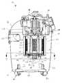
- FIG. 1is an exploded side view of a vacuum having a filter assembly and a filter shaker of the present disclosure
- FIG. 2is a top view of the vacuum
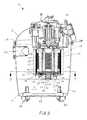
- FIG. 3is a cross-sectional view of the vacuum along the lines 3 - 3 of FIG. 2 with the filter shaker disposed in an operative position as part of the filter assembly;
- FIG. 4is a bottom view of the filter assembly in the operative position
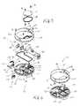
- FIG. 5is an exploded isometric view of the filter shaker
- FIG. 6is an isometric view of the filter shaker partially assembled
- FIG. 7is a cross-sectional view of the vacuum along the lines 7 - 7 of FIG. 3 showing the filter assembly in an operative position;
- FIG. 8is an enlarged detail view of the encircled area shown in FIG. 7 showing a lock of the filter shaker in a locked position.
- a vacuum 10such as an exemplary wet-dry tank vacuum, according to principles of the disclosure includes a vacuum housing 12 defining a vacuum chamber 14 , a vacuum pump 16 arranged to evacuate air from the vacuum chamber, and a filter assembly 18 that prevents particulates inside the vacuum chamber from being drawn into the vacuum pump.
- the filter assembly 18includes a filter 20 , a cage 22 that supports the filter, and a filter shaker 24 carried by the cage in the operative position.
- the filter shaker 24is adapted to shake the cage 22 and/or the filter 20 when selectively activated to shake particulates, such as dust and debris, from the filter, which may otherwise accumulate on the filter during use and clog the filter or otherwise hinder optimum performance of the vacuum.
- the filter shaker 24preferably includes a mounting assembly 26 that is arranged to releasably mount the filter shaker to the filter 20 and/or the cage 22 and/or to a cap removably or permanently attached to the filter 20 and/or the cage 22 , in an operative position, and optionally a locking assembly 28 that is arranged to lock the filter shaker in the position until unlocked.
- the vacuum housing 12preferably is in the form of a tank that includes an upright tank bottom 30 , such as a generally cylindrical canister, and a cover 32 , such as a generally circular lid, that removably covers an opening 34 into a top end of the vacuum chamber 14 .
- the tank bottom 30 and the cover 32define the vacuum chamber 14 , an air inlet 36 into the vacuum chamber 14 , and an air outlet 38 out of the vacuum chamber.
- one or more stabilization members 40such as coasters, legs, and/or feet, are disposed at a bottom end of the bottom portion.
- the stabilization members 40are preferably arranged to facilitate maintaining the vacuum 10 in an upright position, i.e., with the air outlet 38 and the filter 20 disposed in an upper portion of the vacuum chamber 14 above a floor 42 of the vacuum chamber.
- the vacuum housing 12is not limited to the form disclosed and may have any form capable of forming the vacuum chamber 14 in accordance with the principles of the application.
- the vacuum housing 12may include additional features, such as handles 44 , clips 46 to releasably mount the cover 32 to the tank bottom 30 covering the opening 34 , a pump housing 48 to cover the vacuum pump 16 , air grates 50 a partly covering a cooling air inlet and air grates 50 b partly covering a cooling air outlet that cooperate to provide cooling air to a motor of the vacuum pump 16 , and other features as would be well understood in the art.
- the air inlet 36is arranged to allow air to be drawn into the vacuum chamber 14 , such as through a side wall of the tank bottom 30 .
- the air outlet 38is arranged to allow air to be pumped out of the vacuum chamber 14 by the vacuum pump 16 , preferably through an upper portion of the vacuum housing 12 , such as through the cover 32 .
- the vacuum pump 16is carried by the vacuum housing 12 , such as in or on the cover 32 , and arranged to pump air from inside the vacuum chamber 14 through the air outlet 38 to the exterior of the vacuum housing.
- the vacuum pump 16may be any suitable air pump, such as fan or impeller driven by an electric motor, as would be understood by one of ordinary skill.
- the vacuum pump 16When activated, by switching on the electric motor for example, the vacuum pump 16 draws air inside the vacuum chamber 14 out of the vacuum chamber through the filter 20 and the air outlet 38 , which simultaneously draws air into the vacuum chamber through the air inlet 36 .
- the air inlet 36is adapted to have an attachment, such as a vacuum hose or nozzle (not shown), attached thereto.
- the air inlet 36is spaced from the air outlet 38 inside the vacuum chamber such that solids and/or liquids drawn into the vacuum chamber 14 through the air inlet tend to settle onto the floor 42 or at the bottom of the vacuum chamber while the air is drawn through the vacuum chamber and out the air outlet 38 .
- the filter 20preferably includes a central through-bore 52 extending between an upper opening 54 through a top end and a lower opening 56 through a bottom end, such as an elongate tubular filter with an axis extending from the upper opening 54 to the lower opening 56 .
- the filter 20may be formed of any filter material suitable for screening particulates, such as dust and debris, from air drawn out of the vacuum chamber 14 through the air outlet 38 and/or the vacuum pump 16 .
- the filter 20is in a cylindrical form having a pleated paper or fabric filter wall arranged in a cylindrical wall, which is supported by a porous frame 58 , such as a metal or plastic grid, extending between opposite circular frame ends 60 , such as end rings.
- the filter 20may have a sealed or otherwise covered bottom end.
- the cage 22is arranged to hold the filter 20 in the operative position elevated above the floor 42 of the vacuum chamber 14 and surrounding the air 38 outlet so that substantially all air drawn through the air outlet first passes through the filter.
- the cage 22includes a plurality of arms 62 that hang downwardly from the cover 32 surrounding the air outlet 38 , such spaced apart in a circle.
- the arms 62support a plurality of hooks 64 or ledges at the distal, bottom ends thereof. Each hook 64 spans the space between the distal ends of adjacent pairs of the arms 62 .
- the arms 62define an open air way, such as a cylindrical bore, extending from the air outlet 38 to the hooks.
- the arms 62are optionally resilient so that the filter 20 may be installed onto the cage 22 by sliding over the distal ends of the arms 62 and around the hooks 64 and may be removed from the cage by sliding off the distal ends of the arms over the hooks.
- the filter 20When the filter 20 is installed in the operative position on the cage 22 , the filter surrounds the arms 62 and forms a central airway that extends from the open bottom end 56 of the filter and the cage up through the cylindrical bore to the air outlet 38 .
- the filter shaker 24includes a housing 66 , a vibrator assembly 68 carried by the housing, and the mounting assembly 26 disposed on an outer surface of the housing.
- the mounting assembly 26is arranged to attach the housing 66 to the cage 22 and/or the filter 20 and cover the open bottom end 56 of the filter.
- the housing 66preferably is sized and shaped to cover the open bottom end 56 , for example with a flange plate 70 in the form of a circular plate with a diameter at least as large as the open bottom end 56 .
- the housing 66completely blocks the open bottom end 56 to prevent air from entering the central through-bore 52 , and the filter 20 engages against the cover 32 , optionally forming a seal therewith, so that substantially all air pulled through the air outlet 38 must first pass through the filter material and thereby filter particulate matter from the air before entering the air outlet.
- the mounting assembly 26may be arranged to releasably attach the filter shaker 24 to the filter 20 , the frame 58 , and/or the end cap with, for example, one or more hooks carried by resilient arms and arranged to releasably snap to an outer peripheral edge of the end cap, clamps, screws, hook and loop fasteners, or other selectively releasable fasteners.
- the filter shakermounts across the end of the filter
- the housing 66 of the exemplary arrangementincludes an upper housing 66 a connected to a lower housing 66 b that, together, define an enclosed compartment 72 that carries the vibrator assembly 68 .
- the lower housing 66 bhas a circular bottom plate surrounding a well, which defines a lower portion of the enclosed compartment, extending below the bottom plate.
- the upper housing 66 ahas a circular top plate that defines a cover for the enclosed compartment and a circumferential wall 74 extending upwardly from a top side of the top plate adjacent the outer periphery of the top plate, preferably spaced inwardly from the outer annular edge of the top plate.
- the circumferential wall 74extends upwardly away from the flange plate 70 and preferably has a top edge that extends in a circle near the peripheral edge of the flange plate 70 .
- the enclosed compartment 72is disposed underneath or on a bottom side of the flange plate 70 .
- the top plate and the bottom plateare secured together, for example, with screws 76 , other fasteners, welds, and/or adhesives.
- the upper housing 66 aforms a removable cap to cover the lower opening 56 and removably attach to the filter 20 and/or the cage 22
- the lower housing 66 b and the vibrator assembly 68form a filter shaker that is connected to the removable cap with connectors in the form of the screws 76 .
- the vibrator assembly 68includes an electric motor 78 having a motor shaft 80 , an eccentric 82 connected to the motor shaft, an actuator 86 connected to the eccentric with, for example, an eccentric bearing 84 , and optionally a power source 88 , such as one or more batteries, operatively connected to the motor to power the motor.
- the vibrator assembly 68is disposed inside the enclosed compartment 72 , and the actuator 86 is arranged such that rotation of the motor shaft 80 , by powering the motor with the power source 88 , for example, causes the actuator to periodically impact one or more portions of the housing 66 , such as opposing side walls 72 a , 72 b of the enclosed compartment 72 .
- the actuator 86is arranged to impart only lateral impact forces (in relation to the axis of the filter 20 ) and not axial impact forces, by for example, being arranged to impact only the side walls 72 a , 72 b and not impact a bottom wall or top wall of the enclosed compartment 72 .
- the actuator 86includes first and second hammers 86 a , 86 b on opposite lateral sides of a ring carried by the eccentric bearing 84 , wherein the hammers 86 a , 86 b are arranged to alternatingly impact the opposing lateral side walls 72 a , 72 b of the enclosed compartment 72 .
- the motor 78is preferably secured by a flexible mount inside the enclosed compartment with, for example, one or more flexible mounting brackets. In this arrangement, the motor 78 is also able to move to vibrate the filter shaker 24 by, for example, striking against one or more walls of the enclosed compartment 72 at the same time the motor drives the actuator 86 .
- the power source 88 for the motormay be any electrical source sufficient to drive the motor.
- the power source 88is direct current provided by, for example, one or more 9-volt batteries.
- the batteriespreferably are carried by the housing inside the enclosed compartment.
- powermay be provided to the motor by alternating current, for example, supplied from the same power source that powers the vacuum pump, such as standard household electric supply.
- the enclosed compartment 72is optionally water tight and includes a seal, such as a gasket 90 , disposed between the top plate and the bottom plate and surrounding the well.
- the wellis optionally divided into one or more compartments, such as a motor compartment that is adapted to receive the motor, an actuator compartment that is adapted to receive the actuator, and a battery compartment that is adapted to receive the batteries.
- the battery compartmentis preferably separated from the motor and actuator compartments by a wall 92 , and the top plate optionally includes a battery access opening 94 over the battery compartment to allow the batteries to be inserted, removed, and/or replaced without opening the entire enclosed compartment.
- a separate battery cover 96is arranged to cover the battery access opening 94 , and a seal, such as a gasket 98 , seals the battery access opening.
- the battery access opening 94is removably attached to the top plate of the upper housing 66 a with fasteners, such as screws 76 , such that the battery cover 96 may be periodically opened and resealed, for example, to replace the batteries.
- the vibrator assembly 68is turned on and/or off with a switch 100 , such as a rocker switch, a toggle switch, a radio frequency switch, and/or an infrared switch, that is preferably located remote from the filter shaker 24 to be easily accessible by a user, such as on an exterior of the vacuum housing, without requiring the vacuum housing 12 to be opened to actuate the switch.
- a switch 100such as a rocker switch, a toggle switch, a radio frequency switch, and/or an infrared switch, that is preferably located remote from the filter shaker 24 to be easily accessible by a user, such as on an exterior of the vacuum housing, without requiring the vacuum housing 12 to be opened to actuate the switch.
- the switch 100includes a rocker switch located on an exterior the cover, a chord 102 extending into the vacuum chamber 14 , and a plug 104 at the end of the chord.
- a relay switch 106such as a receptacle having a socket for operatively receiving the plug 104 and transmitting switching signals to either power on and/or power off the motor 78 , is also optionally disposed inside the enclosed compartment 72 , such as inside the motor compartment, for example, as best seen in FIG. 5 .
- the plug 104is arranged to be releasably plugged into the socket and thereby connect the switch 100 to the relay switch 106 .
- the filter shaker 24may be selectively disconnected from the switch 100 , which for example allows the filter shaker to be removed from the vacuum chamber 14 while using the vacuum 10 or changing the filter 20 if desired.
- Other remote switching assembliesmay also or alternatively be used, such as a wireless switching device including a radio frequency or infrared frequency transmitter/receiver pair as would be understood in the art.
- the mounting assembly 26includes a connector 110 that allows the filter shaker 24 to be releasably attached to the filter 20 and/or the cage 22 .
- the connector 110may be carried by any portion of the housing 66 that can be arranged to releasably secure the vibrator assembly 68 with the filter 20 and/or the cage 22 .
- the connectoris carried by the circumferential wall 74 of the upper housing 66 a and arranged to releasably mount the upper housing and the entire filter shaker 24 to the cage 22 in the operative position, such as by a friction fit, an interference fit, a bayonet connection, or a threaded connection.
- the circumferential wall 74is arranged to be inserted into an annular gap 112 at the lower end of the filter 20 between the outer annular periphery of the arms 62 and hooks 64 and the inner diameter of the filter 20 .
- the connector 110is disposed on the circumferential wall 74 and includes, for example, a pair of ramps (only one visible) disposed on a radially inner surface of the circumferential wall 74 .
- Each rampincludes an inclined wall segment, such as a helical wall extending between opposite upper and lower ends, that projects radially inwardly from the peripheral wall 74 .
- the rampsare arranged to slide over a ledge projecting radially outwardly from the cage 22 , such as one or more of the hooks 64 , whereby the filter shaker 24 may be mounted to the cage by inserting the circumferential wall 74 axially into the annular gap 112 and rotating the housing 66 about the axis of the cage and the filter 20 , such as in a clockwise direction, to releasably engage the ramps over one or more of the hooks 64 .
- One or more detentsmay be arranged to provide a snap-fit or other resilient locking mechanism between, for example, the circumferential wall 74 or the ramps and one or more of the adjacent arms 62 or hooks 64 .
- other releasable mounting assemblies and/or connector arrangementssuch as a threaded connection or bayonet connection, may be provided, and the disclosure is not intended to be limited to the exemplary mounting assembly and/or connector shown in the drawings.
- the filter shakerincludes two locking assemblies 28 carried by the housing 66 , wherein each locking assembly is adapted to lockingly engage and disengage the cage 22 and/or the filter 20 , as selected by a user, to prevent the filter shaker 24 from vibrating off of the cage while the vibrator assembly is activated.
- each locking assembly 28includes a knob 114 arranged for turning by a user, a cam 116 arranged to be turned in response to turning of the knob, and a lock 118 having a cam follower 120 engaged with the cam.
- a knob 114arranged for turning by a user
- cam 116arranged to be turned in response to turning of the knob
- a lock 118having a cam follower 120 engaged with the cam.
- the knob 114is disposed on the bottom side of the flange plate 70 , preferably spaced from the well a space sufficient to allow easy manipulation by a user's fingers.
- the cam 116is disposed in a cavity defined between the bottom plate and the top plate inside the flange plate and is connected to the knob 114 for rotation with the knob by, for example, a shaft or screw 122 that extends through an aperture in the bottom plate and connects the cam with the knob.
- a sealsuch as an O-ring 124 , is preferably secured around the aperture and arranged to seal the aperture to prevent water and/or debris from entering the cavity through the aperture.
- the lock 118further includes a flap 126 , such as an elongate planar wing having an rotational axis, such as defined by a shaft 128 .
- the cam follower 120is in the form of an arm that extends laterally from the axis defined by the shaft 128 at one end of the flap 126 .
- the lock 118is rotatably secured to the bottom plate and to an underside of the helical ramp, for example with the shaft 128 rotatably received within a socket 129 defined by the helical ramp and/or in the circumferential wall 74 , such that the shaft 128 extends upwardly away from the flange plate 70 and is rotatably secured in an upright position aligned with the circumferential wall 74 .
- the cam follower 120is disposed within the cavity and engages with the cam 116 , whereby the lock 118 is selectively shifted between an unlocked position and a locked position by rotating the knob 114 , which thereby rotates the cam and pivots the cam follower 120 and the flap 126 .
- the locking assembly 28preferably includes a resilient mechanism, such as a spring 130 connected to an end of the arm distal from the axis 128 , which is arranged to automatically pivot the flap 126 to the locked position when the knob 114 is rotated in a locking direction.
- the spring 130preferably is disposed inside the cavity and connected to a the housing 66 , for example at a spring post 132 , at one end and to the distal end of the cam follower 120 at the opposite end, and arranged to be stretched a maximum when the lock 118 is in the unlocked position and to resiliently pull the arm of the cam follower to pivot the flap toward the locked position.
- the flap 126is disposed in a break within the circumferential wall 74 , such as a recess 134 , such that the flap 126 , in the unlocked position, is aligned with the circumferential wall, thereby allowing the filter shaker 24 to rotate with respect to the cage 22 and the filter 20 .
- the lock 118includes one or more teeth 136 disposed on the flap 126 and arranged to engage the cage 20 in a locked position, such as by biting into an outer peripheral surface of one of the hooks 64 , so as to prevent rotational movement of the filter shaker 24 when the lock is in the locked position.
- the lock 118pivots on the shaft 128 , the flaps 126 rotate out of alignment with the peripheral wall 74 , and the teeth 136 engage against the outer peripheral surface of the hook 64 .
- the flaps 126return into alignment with the peripheral wall 74 thereby disengaging the teeth 136 from the hook 64 .
- the locking assembly 28may include additional or alternative locks, as long as the lock or locks are sufficient to prevent the filter shaker from vibrating off of the cage while the vibrator assembly is activated.
- the filter shaker 24may be mounted and demounted from the cage 20 such that the vacuum 10 may be operated with or without the filter shaker.
- the peripheral wall 74is slid into to the annular space 112 between the filter 20 and the cage 22 .
- the housing 66is then rotated about the axis of the filter 20 and the cage 22 such that the end of each ramp of the connectors 110 engages over one of the hooks 64 .
- the ramps of the connectors 110draw the flange plate 70 up tight against the bottom end of the filter 20 , thereby covering and substantially sealing the open bottom end 56 with the housing.
- the switch 100is connected to the relay switch 106 , for example, by inserting the plug 104 into the socket of the relay switch at any convenient time. To demount the filter shaker 24 , the above actions may be reversed.
- the vibrator assembly 68is actuated by activating the switch 100 , which powers the motor 78 and rotates the eccentric 82 and the actuator 86 in an eccentric path.
- the actuator 86periodically impacts laterally (with respect to the axis of the filter) against the side walls of the actuator compartment 72 , thereby causing vibrations that are directed laterally to the axis of the filter 20 , and the motor 78 also vibrates at the same time thereby adding to the overall vibration of the housing 66 .
- the speed of the motor 78is preferably set such that the actuator vibrates very quickly, such as at 10 Hz, 100 Hz, 500 Hz, or more.
- the vibrations from the impactsare transmitted to the filter 20 by engagement between the flange plate 70 , the peripheral wall 74 , and/or the cage 20 , and thereby shake particles, such as dust and debris, off of the filter 20 , and unclogging or cleaning the filter.
- the filter shaker 24is not activated while the vacuum pump 16 is operating so that debris may more easily fall away from the filter 20 when the filter shaker 24 vibrates. Therefore, the vacuum 10 and/or the filter shaker 24 optionally may include a safety switch arranged to prevent the motor from engaging anytime the vacuum pump is engaged.
- the filter shaker 24may be made of any materials and in any method sufficient to produce the structures disclosed herein.
- the housing 60 and locking assemblies 28are formed of metal or plastic, for example by injection molding, and assembled in any sufficient manner as would be understood to a person of ordinary skill.
- the motor 78 and remaining portions of the vacuum 10may also be constructed in any manner as would be understood by a person of ordinary skill.
- the filter shaker 24 disclosed hereinis useful for cleaning the filter 20 in the vacuum 10 quicker and more easily than cleaning the filter by hand.
- the filter shaker 24may also extend the useful life of a filter 20 because the filter may be cleaned more frequently since the filter shaker is easy to actuate from outside of the vacuum.
- the filter shaker 24is a fully self-contained actuatable unit which, for example, can be transferred and/or attached to different filter assemblies and/or vacuums. Therefore, the filter shaker 24 is useful in some arrangements for retrofitting to vacuums and/or filter assemblies that were not originally provided with the filter shaker.
Landscapes
- Chemical & Material Sciences (AREA)
- Chemical Kinetics & Catalysis (AREA)
- Filtering Of Dispersed Particles In Gases (AREA)
- Sampling And Sample Adjustment (AREA)
Abstract
Description
Claims (20)
Priority Applications (5)
| Application Number | Priority Date | Filing Date | Title |
|---|---|---|---|
| US13/455,738US9038236B2 (en) | 2012-04-25 | 2012-04-25 | Filter shaker |
| AU2012204145AAU2012204145C1 (en) | 2012-04-25 | 2012-07-12 | Filter shaker |
| CA2782900ACA2782900C (en) | 2012-04-25 | 2012-07-12 | Filter shaker |
| MX2012013325AMX2012013325A (en) | 2012-04-25 | 2012-11-15 | Filter shaker. |
| EP12196061.1AEP2656895B1 (en) | 2012-04-25 | 2012-12-07 | Filter shaker |
Applications Claiming Priority (1)
| Application Number | Priority Date | Filing Date | Title |
|---|---|---|---|
| US13/455,738US9038236B2 (en) | 2012-04-25 | 2012-04-25 | Filter shaker |
Publications (2)
| Publication Number | Publication Date |
|---|---|
| US20130283563A1 US20130283563A1 (en) | 2013-10-31 |
| US9038236B2true US9038236B2 (en) | 2015-05-26 |
Family
ID=47290816
Family Applications (1)
| Application Number | Title | Priority Date | Filing Date |
|---|---|---|---|
| US13/455,738Active2034-01-26US9038236B2 (en) | 2012-04-25 | 2012-04-25 | Filter shaker |
Country Status (5)
| Country | Link |
|---|---|
| US (1) | US9038236B2 (en) |
| EP (1) | EP2656895B1 (en) |
| AU (1) | AU2012204145C1 (en) |
| CA (1) | CA2782900C (en) |
| MX (1) | MX2012013325A (en) |
Cited By (4)
| Publication number | Priority date | Publication date | Assignee | Title |
|---|---|---|---|---|
| US20180235419A1 (en)* | 2017-02-17 | 2018-08-23 | Makita Corporation | Dust collector |
| US10368706B1 (en) | 2018-07-17 | 2019-08-06 | Shop Vac Corporation | Vacuum filter having annular catch |
| US10869586B2 (en) | 2016-11-17 | 2020-12-22 | Karcher North America, Inc. | Portable vacuum and related accessories |
| US11547257B2 (en) | 2020-02-04 | 2023-01-10 | Dustless Depot, Llc | Vacuum bag with inlet gasket and closure seal |
Families Citing this family (9)
| Publication number | Priority date | Publication date | Assignee | Title |
|---|---|---|---|---|
| US10543622B2 (en)* | 2008-07-03 | 2020-01-28 | JPL Global, LLC | Rotatable filter system and methodology |
| DE102016121582A1 (en)* | 2016-11-10 | 2018-05-17 | Seepex Gmbh | Cavity Pump |
| CN206928712U (en) | 2017-06-22 | 2018-01-26 | 明达实业(厦门)有限公司 | River generator suspension frame installing structure |
| US11058273B2 (en) | 2017-09-28 | 2021-07-13 | Techtronic Floor Care Technology Limited | Vacuum cleaner |
| US11235433B2 (en)* | 2017-12-22 | 2022-02-01 | Milwaukee Electric Tool Corporation | Dust collector with filter cleaning mechanism |
| US11673217B2 (en) | 2018-11-19 | 2023-06-13 | Milwaukee Electric Tool Corporation | Dust collector including filter cleaning mechanism |
| CN211383723U (en)* | 2019-11-01 | 2020-09-01 | 明达实业(厦门)有限公司 | Suspension structure of swimming machine |
| DE102020214439B4 (en)* | 2020-11-17 | 2023-03-16 | Christof-Herbert Diener | Vacuum device with a sintered metal bag filter and use of an exhaust particulate filter in a vacuum device |
| WO2023081788A1 (en)* | 2021-11-04 | 2023-05-11 | Pyne Inc. | Self-cleaning filter media |
Citations (65)
| Publication number | Priority date | Publication date | Assignee | Title |
|---|---|---|---|---|
| US2437034A (en) | 1944-09-06 | 1948-03-02 | Meinzer Gotthold Harry | Polishing machine |
| US2543342A (en) | 1945-08-21 | 1951-02-27 | Timm Aircraft Corp | Suction cleaner with switch circuit |
| US2585508A (en) | 1946-12-28 | 1952-02-12 | Hoover Co | Filter shaker for suction cleaners |
| US3160908A (en) | 1961-09-13 | 1964-12-15 | Tennant Co G H | Power sweeper air filter and dust collector system |
| US3591888A (en) | 1969-12-22 | 1971-07-13 | Matsushita Electric Industrial Co Ltd | Electrically operated vacuum cleaner equipped with automatic filter-cleaning means |
| US3639940A (en) | 1969-08-22 | 1972-02-08 | Tennant Co | Filter chamber |
| US3653189A (en) | 1969-01-20 | 1972-04-04 | Sanyo Electric Co | Vacuum cleaner |
| US3877901A (en) | 1973-05-29 | 1975-04-15 | Wheelabrator Frye Inc | Bag filters |
| US3938971A (en) | 1974-10-07 | 1976-02-17 | The Air Preheater Company, Inc. | Bag filter cleaning device |
| US3951628A (en) | 1973-12-26 | 1976-04-20 | Luther Eskijian | Portable filter bag assembly |
| US4099940A (en) | 1977-03-17 | 1978-07-11 | Fmc Corporation | Impulse filter cleaner |
| EP0024636A1 (en) | 1979-08-16 | 1981-03-11 | Hitachi, Ltd. | Vacuum cleaner |
| GB2055617A (en) | 1979-07-23 | 1981-03-11 | Tennant Co | Suction cleaner |
| US4289630A (en) | 1979-12-10 | 1981-09-15 | Industrial Filter & Pump Mfg. Co. | Filter cake removal method and apparatus |
| US4297114A (en) | 1978-01-24 | 1981-10-27 | Hutchins Manufacturing Co. | Vacuum cleaner having bag cleaning apparatus |
| US4328014A (en) | 1981-04-22 | 1982-05-04 | The Scott & Fetzer Company | Sweeper hopper with filter assembly |
| US4345353A (en) | 1979-07-23 | 1982-08-24 | Tennant Company | Filtering device |
| US4510815A (en) | 1981-07-18 | 1985-04-16 | Losenhausen Maschinenbau Ag | Flyweight vibrator designed as directional vibrator |
| US4533371A (en) | 1982-04-25 | 1985-08-06 | Kabushiki Kaisha Suiden | Vacuum cleaner |
| US4557738A (en) | 1982-05-26 | 1985-12-10 | Menasian David R | Vacuum collector |
| US4580313A (en) | 1983-09-12 | 1986-04-08 | Tennant Company | Walk behind floor maintenance machine |
| US4592764A (en) | 1983-06-30 | 1986-06-03 | Sharp Kabushiki Kaisha | Vacuum cleaner |
| US4675032A (en) | 1986-09-29 | 1987-06-23 | Southwest Manufacturers & Distributors, Inc. | Vacuum cleaner bag with oscillating tube |
| US4704144A (en) | 1986-02-24 | 1987-11-03 | Donaldson Company, Inc. | Air filtering apparatus |
| US4787923A (en) | 1986-08-27 | 1988-11-29 | Tennant Company | Apparatus for cleaning an air filter |
| US4792344A (en) | 1986-08-26 | 1988-12-20 | Donaldson Company, Inc. | Air filtering method and apparatus |
| US4868949A (en) | 1988-11-25 | 1989-09-26 | Loveless Michael L | Ash vacuum adapter |
| US5013333A (en) | 1990-04-13 | 1991-05-07 | Tennant Company | Unattended air cleaning system for surface maintenance machine |
| US5087274A (en) | 1990-07-16 | 1992-02-11 | The Spencer Turbine Company | Bag shaker |
| US5090083A (en) | 1990-05-22 | 1992-02-25 | Castex Industries, Inc. | Wide area carpet vacuum cleaner |
| US5152027A (en) | 1990-04-02 | 1992-10-06 | Shop-Vac Corporation | Industrial sweeper |
| US5194077A (en) | 1990-03-20 | 1993-03-16 | Clarke Industries, Inc. | Dual chamber filter assembly with shaker |
| US5223005A (en) | 1992-08-14 | 1993-06-29 | Aercology, Inc. | Dust and fume collector |
| US5259087A (en) | 1991-12-27 | 1993-11-09 | Loveless Michael L | Ash vacuum |
| US5603740A (en) | 1995-03-27 | 1997-02-18 | Roy; Michel | Suction activated reciprocating system |
| US5647093A (en) | 1996-06-18 | 1997-07-15 | Tennant Company | Sweeper with dual seal filter |
| US5667682A (en) | 1995-10-25 | 1997-09-16 | Water Renewal Systems L.P. | Self-cleaning filtration apparatus |
| US5681363A (en) | 1996-03-18 | 1997-10-28 | Tucker; Deborah R. | Vacuum cleaner filter shaker |
| US5690710A (en) | 1996-08-13 | 1997-11-25 | Stephan; Paul F. | Self-cleaning filter |
| US5704956A (en) | 1996-02-26 | 1998-01-06 | Loveless; Michael L. | Filter cleaning system for an ash vacuum |
| US5711775A (en) | 1996-04-15 | 1998-01-27 | Tennant Company | Sweeper with electromagnetic filter cleaning |
| US5829094A (en) | 1997-02-19 | 1998-11-03 | Tennant Company | Sweeper with electromagnetic filter cleaning |
| US6117200A (en) | 1996-04-15 | 2000-09-12 | Tennant Company | Electromagnetic filter cleaning system |
| US6192550B1 (en) | 1999-01-29 | 2001-02-27 | Sanyo Electric Co., Ltd. | Dust-collecting device for vacuum cleaner and upright type vacuum cleaner |
| US6202765B1 (en) | 1998-03-13 | 2001-03-20 | Tamrock Voest-Alpine Bergtechnik Gesellschaft M.B.H. | Device having a filter, a filter vibrating means and a scraper used for sucking off drillings |
| US6471751B1 (en) | 2000-09-11 | 2002-10-29 | Houston Industrial Corporation | Polycyclonic vacuum collectors for virtually non-stop environmental remediation |
| US6569218B2 (en) | 2001-03-08 | 2003-05-27 | David Edmond Dudley | Self spin-cleaning canister vacuum |
| US6598263B2 (en) | 2001-05-09 | 2003-07-29 | The Hoover Company | Vacuum cleaner dirt collecting system with filter cleaning devices |
| US6638329B2 (en) | 2000-07-07 | 2003-10-28 | Hilti Aktiengesellschaft | Filter having a folded dust filter element and a cleaning device for the folded dust filter element |
| US20040025287A1 (en)* | 2000-10-03 | 2004-02-12 | Mccormick Michael J. | Airflow system for bagless vacuum cleaner |
| US6854157B2 (en) | 2002-02-13 | 2005-02-15 | Federal Signal Corporation | Debris collection systems and vehicles |
| US20050091784A1 (en) | 2003-08-05 | 2005-05-05 | Daniel Bone | Self-cleaning vacuum cleaner and receptacle therefor |
| US6949130B1 (en) | 1999-11-04 | 2005-09-27 | Techtronic Industries Co. Ltd. | Dust and dirt separation assembly |
| US20070000219A1 (en) | 2005-06-30 | 2007-01-04 | Park Chan J | Air purifier |
| US20070209148A1 (en) | 2006-03-08 | 2007-09-13 | Panasonic Corporation Of North America | Floor cleaning apparatus with filter cleaning system |
| EP1834565A1 (en) | 2006-03-14 | 2007-09-19 | Soteco S.p.A. | Filtering apparatus with percussion means |
| US20080271420A1 (en)* | 2007-03-07 | 2008-11-06 | Richard William Wellens | Cyclonic Filter For Surface Maintenance Machine |
| US7485167B2 (en) | 2005-06-15 | 2009-02-03 | Vac-U-Max | Shaker mechanism for vacuum cleaner filter bag |
| EP2085012A1 (en) | 2008-01-31 | 2009-08-05 | BLACK & DECKER INC. | Vacuum filter cleaning device |
| US20090217479A1 (en) | 2008-02-29 | 2009-09-03 | Tennant Company | Filter Shaker Assembly for Sweeping Machine |
| WO2011010786A1 (en) | 2009-07-24 | 2011-01-27 | 삼성광주전자 주식회사 | Dust collector for a vacuum cleaner having a dust removal function |
| US7896936B2 (en) | 2007-03-06 | 2011-03-01 | Tennant Company | Filter cleaning apparatus |
| JP2011055975A (en) | 2009-09-09 | 2011-03-24 | Panasonic Corp | Vacuum cleaner |
| US8012225B2 (en) | 2005-09-12 | 2011-09-06 | Aertecnica S.P.A. | Filter support for a vacuum cleaner |
| WO2012017606A1 (en) | 2010-08-05 | 2012-02-09 | パナソニック株式会社 | Electric vacuum cleaner |
- 2012
- 2012-04-25USUS13/455,738patent/US9038236B2/enactiveActive
- 2012-07-12AUAU2012204145Apatent/AU2012204145C1/ennot_activeCeased
- 2012-07-12CACA2782900Apatent/CA2782900C/ennot_activeExpired - Fee Related
- 2012-11-15MXMX2012013325Apatent/MX2012013325A/ennot_activeApplication Discontinuation
- 2012-12-07EPEP12196061.1Apatent/EP2656895B1/ennot_activeNot-in-force
Patent Citations (69)
| Publication number | Priority date | Publication date | Assignee | Title |
|---|---|---|---|---|
| US2437034A (en) | 1944-09-06 | 1948-03-02 | Meinzer Gotthold Harry | Polishing machine |
| US2543342A (en) | 1945-08-21 | 1951-02-27 | Timm Aircraft Corp | Suction cleaner with switch circuit |
| US2585508A (en) | 1946-12-28 | 1952-02-12 | Hoover Co | Filter shaker for suction cleaners |
| US3160908A (en) | 1961-09-13 | 1964-12-15 | Tennant Co G H | Power sweeper air filter and dust collector system |
| US3653189A (en) | 1969-01-20 | 1972-04-04 | Sanyo Electric Co | Vacuum cleaner |
| US3639940A (en) | 1969-08-22 | 1972-02-08 | Tennant Co | Filter chamber |
| US3591888A (en) | 1969-12-22 | 1971-07-13 | Matsushita Electric Industrial Co Ltd | Electrically operated vacuum cleaner equipped with automatic filter-cleaning means |
| US3877901A (en) | 1973-05-29 | 1975-04-15 | Wheelabrator Frye Inc | Bag filters |
| US3951628A (en) | 1973-12-26 | 1976-04-20 | Luther Eskijian | Portable filter bag assembly |
| US3938971A (en) | 1974-10-07 | 1976-02-17 | The Air Preheater Company, Inc. | Bag filter cleaning device |
| US4099940A (en) | 1977-03-17 | 1978-07-11 | Fmc Corporation | Impulse filter cleaner |
| US4297114A (en) | 1978-01-24 | 1981-10-27 | Hutchins Manufacturing Co. | Vacuum cleaner having bag cleaning apparatus |
| GB2055617A (en) | 1979-07-23 | 1981-03-11 | Tennant Co | Suction cleaner |
| US4258451A (en) | 1979-07-23 | 1981-03-31 | Tennant Company | Surface sweeping machine |
| US4345353A (en) | 1979-07-23 | 1982-08-24 | Tennant Company | Filtering device |
| EP0024636A1 (en) | 1979-08-16 | 1981-03-11 | Hitachi, Ltd. | Vacuum cleaner |
| US4289630A (en) | 1979-12-10 | 1981-09-15 | Industrial Filter & Pump Mfg. Co. | Filter cake removal method and apparatus |
| US4328014A (en) | 1981-04-22 | 1982-05-04 | The Scott & Fetzer Company | Sweeper hopper with filter assembly |
| US4510815A (en) | 1981-07-18 | 1985-04-16 | Losenhausen Maschinenbau Ag | Flyweight vibrator designed as directional vibrator |
| US4533371A (en) | 1982-04-25 | 1985-08-06 | Kabushiki Kaisha Suiden | Vacuum cleaner |
| US4557738A (en) | 1982-05-26 | 1985-12-10 | Menasian David R | Vacuum collector |
| US4592764A (en) | 1983-06-30 | 1986-06-03 | Sharp Kabushiki Kaisha | Vacuum cleaner |
| US4580313A (en) | 1983-09-12 | 1986-04-08 | Tennant Company | Walk behind floor maintenance machine |
| US4704144A (en) | 1986-02-24 | 1987-11-03 | Donaldson Company, Inc. | Air filtering apparatus |
| US4792344A (en) | 1986-08-26 | 1988-12-20 | Donaldson Company, Inc. | Air filtering method and apparatus |
| US4787923A (en) | 1986-08-27 | 1988-11-29 | Tennant Company | Apparatus for cleaning an air filter |
| US4675032A (en) | 1986-09-29 | 1987-06-23 | Southwest Manufacturers & Distributors, Inc. | Vacuum cleaner bag with oscillating tube |
| US4868949A (en) | 1988-11-25 | 1989-09-26 | Loveless Michael L | Ash vacuum adapter |
| US5194077A (en) | 1990-03-20 | 1993-03-16 | Clarke Industries, Inc. | Dual chamber filter assembly with shaker |
| US5152027A (en) | 1990-04-02 | 1992-10-06 | Shop-Vac Corporation | Industrial sweeper |
| US5013333A (en) | 1990-04-13 | 1991-05-07 | Tennant Company | Unattended air cleaning system for surface maintenance machine |
| US5090083A (en) | 1990-05-22 | 1992-02-25 | Castex Industries, Inc. | Wide area carpet vacuum cleaner |
| US5087274A (en) | 1990-07-16 | 1992-02-11 | The Spencer Turbine Company | Bag shaker |
| US5259087A (en) | 1991-12-27 | 1993-11-09 | Loveless Michael L | Ash vacuum |
| US5223005A (en) | 1992-08-14 | 1993-06-29 | Aercology, Inc. | Dust and fume collector |
| US5603740A (en) | 1995-03-27 | 1997-02-18 | Roy; Michel | Suction activated reciprocating system |
| US5667682A (en) | 1995-10-25 | 1997-09-16 | Water Renewal Systems L.P. | Self-cleaning filtration apparatus |
| US5704956A (en) | 1996-02-26 | 1998-01-06 | Loveless; Michael L. | Filter cleaning system for an ash vacuum |
| US5681363A (en) | 1996-03-18 | 1997-10-28 | Tucker; Deborah R. | Vacuum cleaner filter shaker |
| US6117200A (en) | 1996-04-15 | 2000-09-12 | Tennant Company | Electromagnetic filter cleaning system |
| US5711775A (en) | 1996-04-15 | 1998-01-27 | Tennant Company | Sweeper with electromagnetic filter cleaning |
| US5647093A (en) | 1996-06-18 | 1997-07-15 | Tennant Company | Sweeper with dual seal filter |
| US5690710A (en) | 1996-08-13 | 1997-11-25 | Stephan; Paul F. | Self-cleaning filter |
| US5829094A (en) | 1997-02-19 | 1998-11-03 | Tennant Company | Sweeper with electromagnetic filter cleaning |
| US6202765B1 (en) | 1998-03-13 | 2001-03-20 | Tamrock Voest-Alpine Bergtechnik Gesellschaft M.B.H. | Device having a filter, a filter vibrating means and a scraper used for sucking off drillings |
| US6192550B1 (en) | 1999-01-29 | 2001-02-27 | Sanyo Electric Co., Ltd. | Dust-collecting device for vacuum cleaner and upright type vacuum cleaner |
| US6949130B1 (en) | 1999-11-04 | 2005-09-27 | Techtronic Industries Co. Ltd. | Dust and dirt separation assembly |
| US6638329B2 (en) | 2000-07-07 | 2003-10-28 | Hilti Aktiengesellschaft | Filter having a folded dust filter element and a cleaning device for the folded dust filter element |
| US6471751B1 (en) | 2000-09-11 | 2002-10-29 | Houston Industrial Corporation | Polycyclonic vacuum collectors for virtually non-stop environmental remediation |
| US20040025287A1 (en)* | 2000-10-03 | 2004-02-12 | Mccormick Michael J. | Airflow system for bagless vacuum cleaner |
| US6569218B2 (en) | 2001-03-08 | 2003-05-27 | David Edmond Dudley | Self spin-cleaning canister vacuum |
| US6598263B2 (en) | 2001-05-09 | 2003-07-29 | The Hoover Company | Vacuum cleaner dirt collecting system with filter cleaning devices |
| US6854157B2 (en) | 2002-02-13 | 2005-02-15 | Federal Signal Corporation | Debris collection systems and vehicles |
| US20050091784A1 (en) | 2003-08-05 | 2005-05-05 | Daniel Bone | Self-cleaning vacuum cleaner and receptacle therefor |
| US7485167B2 (en) | 2005-06-15 | 2009-02-03 | Vac-U-Max | Shaker mechanism for vacuum cleaner filter bag |
| US20070000219A1 (en) | 2005-06-30 | 2007-01-04 | Park Chan J | Air purifier |
| US8012225B2 (en) | 2005-09-12 | 2011-09-06 | Aertecnica S.P.A. | Filter support for a vacuum cleaner |
| US20070209148A1 (en) | 2006-03-08 | 2007-09-13 | Panasonic Corporation Of North America | Floor cleaning apparatus with filter cleaning system |
| EP1834565A1 (en) | 2006-03-14 | 2007-09-19 | Soteco S.p.A. | Filtering apparatus with percussion means |
| US7896936B2 (en) | 2007-03-06 | 2011-03-01 | Tennant Company | Filter cleaning apparatus |
| US20080271420A1 (en)* | 2007-03-07 | 2008-11-06 | Richard William Wellens | Cyclonic Filter For Surface Maintenance Machine |
| EP2085012A1 (en) | 2008-01-31 | 2009-08-05 | BLACK & DECKER INC. | Vacuum filter cleaning device |
| US8327487B2 (en) | 2008-01-31 | 2012-12-11 | Black & Decker Inc. | Vacuum filter cleaning device |
| US8256061B2 (en) | 2008-02-29 | 2012-09-04 | Tennant Company | Filter shaker assembly for sweeping machine |
| US20090217479A1 (en) | 2008-02-29 | 2009-09-03 | Tennant Company | Filter Shaker Assembly for Sweeping Machine |
| WO2011010786A1 (en) | 2009-07-24 | 2011-01-27 | 삼성광주전자 주식회사 | Dust collector for a vacuum cleaner having a dust removal function |
| US20120117927A1 (en) | 2009-07-24 | 2012-05-17 | Jang Keun Oh | Dust collector for a vacuum cleaner having a dust removal function |
| JP2011055975A (en) | 2009-09-09 | 2011-03-24 | Panasonic Corp | Vacuum cleaner |
| WO2012017606A1 (en) | 2010-08-05 | 2012-02-09 | パナソニック株式会社 | Electric vacuum cleaner |
Non-Patent Citations (5)
| Title |
|---|
| Automatic Shake Telecontrol Dry Model product brochure, Soteco SpA (date not available). |
| European Search Report, European patent application No. EP12196061, May 27, 2013. |
| Filter Shaker List from Alto® Operator's Manual, American-Lincoln Technology (1995). |
| Illustration of Hose Carrier Design, Shop Vac Corporation, applicant's internal files (Mar. 13, 1997). |
| Love-Less AshVac system product sheet (date not available). |
Cited By (6)
| Publication number | Priority date | Publication date | Assignee | Title |
|---|---|---|---|---|
| US10869586B2 (en) | 2016-11-17 | 2020-12-22 | Karcher North America, Inc. | Portable vacuum and related accessories |
| US20180235419A1 (en)* | 2017-02-17 | 2018-08-23 | Makita Corporation | Dust collector |
| US11134816B2 (en)* | 2017-02-17 | 2021-10-05 | Makita Corporation | Dust collector |
| US10368706B1 (en) | 2018-07-17 | 2019-08-06 | Shop Vac Corporation | Vacuum filter having annular catch |
| US11304579B2 (en) | 2018-07-17 | 2022-04-19 | Shop Vac Corporation | Vacuum filter having annular catch |
| US11547257B2 (en) | 2020-02-04 | 2023-01-10 | Dustless Depot, Llc | Vacuum bag with inlet gasket and closure seal |
Also Published As
| Publication number | Publication date |
|---|---|
| AU2012204145C1 (en) | 2017-10-19 |
| CA2782900A1 (en) | 2013-10-25 |
| US20130283563A1 (en) | 2013-10-31 |
| AU2012204145B2 (en) | 2017-06-15 |
| EP2656895A1 (en) | 2013-10-30 |
| AU2012204145A1 (en) | 2013-11-14 |
| MX2012013325A (en) | 2013-10-24 |
| EP2656895B1 (en) | 2016-05-18 |
| CA2782900C (en) | 2019-07-30 |
Similar Documents
| Publication | Publication Date | Title |
|---|---|---|
| US9038236B2 (en) | Filter shaker | |
| US11503970B2 (en) | Vacuum cleaner | |
| EP3862066B1 (en) | Air cleaner | |
| US8292979B2 (en) | Vacuum cleaner with a removable screen | |
| US9091092B1 (en) | Pool cleaner | |
| CA2660913C (en) | Easy access filter assembly for a wet/dry vacuum appliance | |
| US7752708B2 (en) | Floor cleaning apparatus with filter cleaning system | |
| JP3639250B2 (en) | Vacuum cleaner filter mounting device | |
| US20090144931A1 (en) | Hand-Held Cordless Vacuum Cleaner | |
| KR100474807B1 (en) | Vacuum cleaner | |
| US20080307597A1 (en) | Upright vacuum cleaner | |
| CA2887959A1 (en) | Upright vacuum cleaner | |
| CN102281809A (en) | Magnetic vacuum tool mount | |
| US20140251387A1 (en) | Method and apparatus for cleaning a filter | |
| KR102116010B1 (en) | Air cleaner combined with portable fan for vehicle | |
| JP2005061700A (en) | Air cleaner | |
| KR100547416B1 (en) | Dust collection unit mounting device of vacuum cleaner | |
| CA2742391A1 (en) | Wet/dry vacuum appliance, dust filtration attachment therefore, and methods of use | |
| CA2617707C (en) | Floor cleaning apparatus with filter cleaning system | |
| KR101033292B1 (en) | Handheld Hand Cleaner |
Legal Events
| Date | Code | Title | Description |
|---|---|---|---|
| AS | Assignment | Owner name:SHOP VAC CORPORATION, PENNSYLVANIA Free format text:ASSIGNMENT OF ASSIGNORS INTEREST;ASSIGNORS:FRY, KEVIN D.;CREVLING, ROBERT L., JR.;BUSS, RANDY L.;REEL/FRAME:028110/0146 Effective date:20120424 | |
| AS | Assignment | Owner name:GENERAL ELECTRIC CAPITAL CORPORATION, CONNECTICUT Free format text:SECURITY AGREEMENT;ASSIGNOR:SHOP VAC CORPORATION;REEL/FRAME:031892/0631 Effective date:20131224 | |
| STCF | Information on status: patent grant | Free format text:PATENTED CASE | |
| AS | Assignment | Owner name:JPMORGAN CHASE BANK, N.A., AS ADMINISTRATIVE AGENT, NEW YORK Free format text:SECURITY INTEREST;ASSIGNOR:SHOP VAC CORPORATION;REEL/FRAME:044956/0302 Effective date:20171120 Owner name:SHOP VAC CORPORATION, PENNSYLVANIA Free format text:RELEASE BY SECURED PARTY;ASSIGNOR:WELLS FARGO BANK, NATIONAL ASSOCIATION, AS SUCCESSOR US AGENT;REEL/FRAME:044798/0760 Effective date:20171120 Owner name:JPMORGAN CHASE BANK, N.A., AS ADMINISTRATIVE AGENT Free format text:SECURITY INTEREST;ASSIGNOR:SHOP VAC CORPORATION;REEL/FRAME:044956/0302 Effective date:20171120 | |
| MAFP | Maintenance fee payment | Free format text:PAYMENT OF MAINTENANCE FEE, 4TH YEAR, LARGE ENTITY (ORIGINAL EVENT CODE: M1551); ENTITY STATUS OF PATENT OWNER: LARGE ENTITY Year of fee payment:4 | |
| AS | Assignment | Owner name:SHOP VAC CORPORATION, PENNSYLVANIA Free format text:RELEASE BY SECURED PARTY;ASSIGNOR:JPMORGAN CHASE BANK, N.A., AS ADMINISTRATIVE AGENT;REEL/FRAME:054976/0664 Effective date:20201223 | |
| FEPP | Fee payment procedure | Free format text:MAINTENANCE FEE REMINDER MAILED (ORIGINAL EVENT CODE: REM.); ENTITY STATUS OF PATENT OWNER: LARGE ENTITY | |
| FEPP | Fee payment procedure | Free format text:7.5 YR SURCHARGE - LATE PMT W/IN 6 MO, LARGE ENTITY (ORIGINAL EVENT CODE: M1555); ENTITY STATUS OF PATENT OWNER: LARGE ENTITY | |
| MAFP | Maintenance fee payment | Free format text:PAYMENT OF MAINTENANCE FEE, 8TH YEAR, LARGE ENTITY (ORIGINAL EVENT CODE: M1552); ENTITY STATUS OF PATENT OWNER: LARGE ENTITY Year of fee payment:8 | |
| AS | Assignment | Owner name:GREAT STAR TOOLS USA, INC., NEW JERSEY Free format text:ASSIGNMENT OF ASSIGNORS INTEREST;ASSIGNOR:SHOP VAC CORPORATION;REEL/FRAME:066778/0864 Effective date:20201223 |