US9037426B2 - Systems and methods for determining cell capacity values in a multi-cell battery - Google Patents
Systems and methods for determining cell capacity values in a multi-cell batteryDownload PDFInfo
- Publication number
- US9037426B2 US9037426B2US13/107,171US201113107171AUS9037426B2US 9037426 B2US9037426 B2US 9037426B2US 201113107171 AUS201113107171 AUS 201113107171AUS 9037426 B2US9037426 B2US 9037426B2
- Authority
- US
- United States
- Prior art keywords
- charge
- pack
- state
- values
- cell
- Prior art date
- Legal status (The legal status is an assumption and is not a legal conclusion. Google has not performed a legal analysis and makes no representation as to the accuracy of the status listed.)
- Expired - Fee Related, expires
Links
Images


Classifications
- G01R31/3624—
- G—PHYSICS
- G01—MEASURING; TESTING
- G01R—MEASURING ELECTRIC VARIABLES; MEASURING MAGNETIC VARIABLES
- G01R31/00—Arrangements for testing electric properties; Arrangements for locating electric faults; Arrangements for electrical testing characterised by what is being tested not provided for elsewhere
- G01R31/36—Arrangements for testing, measuring or monitoring the electrical condition of accumulators or electric batteries, e.g. capacity or state of charge [SoC]
- G01R31/382—Arrangements for monitoring battery or accumulator variables, e.g. SoC
- G01R31/3842—Arrangements for monitoring battery or accumulator variables, e.g. SoC combining voltage and current measurements
- B60L11/1861—
- B60L11/1866—
- B—PERFORMING OPERATIONS; TRANSPORTING
- B60—VEHICLES IN GENERAL
- B60L—PROPULSION OF ELECTRICALLY-PROPELLED VEHICLES; SUPPLYING ELECTRIC POWER FOR AUXILIARY EQUIPMENT OF ELECTRICALLY-PROPELLED VEHICLES; ELECTRODYNAMIC BRAKE SYSTEMS FOR VEHICLES IN GENERAL; MAGNETIC SUSPENSION OR LEVITATION FOR VEHICLES; MONITORING OPERATING VARIABLES OF ELECTRICALLY-PROPELLED VEHICLES; ELECTRIC SAFETY DEVICES FOR ELECTRICALLY-PROPELLED VEHICLES
- B60L58/00—Methods or circuit arrangements for monitoring or controlling batteries or fuel cells, specially adapted for electric vehicles
- B60L58/10—Methods or circuit arrangements for monitoring or controlling batteries or fuel cells, specially adapted for electric vehicles for monitoring or controlling batteries
- B60L58/12—Methods or circuit arrangements for monitoring or controlling batteries or fuel cells, specially adapted for electric vehicles for monitoring or controlling batteries responding to state of charge [SoC]
- B—PERFORMING OPERATIONS; TRANSPORTING
- B60—VEHICLES IN GENERAL
- B60L—PROPULSION OF ELECTRICALLY-PROPELLED VEHICLES; SUPPLYING ELECTRIC POWER FOR AUXILIARY EQUIPMENT OF ELECTRICALLY-PROPELLED VEHICLES; ELECTRODYNAMIC BRAKE SYSTEMS FOR VEHICLES IN GENERAL; MAGNETIC SUSPENSION OR LEVITATION FOR VEHICLES; MONITORING OPERATING VARIABLES OF ELECTRICALLY-PROPELLED VEHICLES; ELECTRIC SAFETY DEVICES FOR ELECTRICALLY-PROPELLED VEHICLES
- B60L58/00—Methods or circuit arrangements for monitoring or controlling batteries or fuel cells, specially adapted for electric vehicles
- B60L58/10—Methods or circuit arrangements for monitoring or controlling batteries or fuel cells, specially adapted for electric vehicles for monitoring or controlling batteries
- B60L58/18—Methods or circuit arrangements for monitoring or controlling batteries or fuel cells, specially adapted for electric vehicles for monitoring or controlling batteries of two or more battery modules
- B60L58/22—Balancing the charge of battery modules
- H—ELECTRICITY
- H02—GENERATION; CONVERSION OR DISTRIBUTION OF ELECTRIC POWER
- H02J—CIRCUIT ARRANGEMENTS OR SYSTEMS FOR SUPPLYING OR DISTRIBUTING ELECTRIC POWER; SYSTEMS FOR STORING ELECTRIC ENERGY
- H02J7/00—Circuit arrangements for charging or depolarising batteries or for supplying loads from batteries
- H02J7/007—Regulation of charging or discharging current or voltage
- H02J7/00712—Regulation of charging or discharging current or voltage the cycle being controlled or terminated in response to electric parameters
- H02J7/00714—Regulation of charging or discharging current or voltage the cycle being controlled or terminated in response to electric parameters in response to battery charging or discharging current
- H02J7/00716—Regulation of charging or discharging current or voltage the cycle being controlled or terminated in response to electric parameters in response to battery charging or discharging current in response to integrated charge or discharge current
- H—ELECTRICITY
- H02—GENERATION; CONVERSION OR DISTRIBUTION OF ELECTRIC POWER
- H02J—CIRCUIT ARRANGEMENTS OR SYSTEMS FOR SUPPLYING OR DISTRIBUTING ELECTRIC POWER; SYSTEMS FOR STORING ELECTRIC ENERGY
- H02J7/00—Circuit arrangements for charging or depolarising batteries or for supplying loads from batteries
- H02J7/02—Circuit arrangements for charging or depolarising batteries or for supplying loads from batteries for charging batteries from AC mains by converters
- H02J7/04—Regulation of charging current or voltage
- H02J7/044—
- Y—GENERAL TAGGING OF NEW TECHNOLOGICAL DEVELOPMENTS; GENERAL TAGGING OF CROSS-SECTIONAL TECHNOLOGIES SPANNING OVER SEVERAL SECTIONS OF THE IPC; TECHNICAL SUBJECTS COVERED BY FORMER USPC CROSS-REFERENCE ART COLLECTIONS [XRACs] AND DIGESTS
- Y02—TECHNOLOGIES OR APPLICATIONS FOR MITIGATION OR ADAPTATION AGAINST CLIMATE CHANGE
- Y02T—CLIMATE CHANGE MITIGATION TECHNOLOGIES RELATED TO TRANSPORTATION
- Y02T10/00—Road transport of goods or passengers
- Y02T10/60—Other road transportation technologies with climate change mitigation effect
- Y02T10/70—Energy storage systems for electromobility, e.g. batteries
- Y02T10/7005—
- Y02T10/7061—
Definitions
- the present inventionrelates generally to determining the cell capacities in a multi-cell battery, and more particularly to systems and methods determining cell capacity values based on the state of charge of the battery.
- Automotive technologyis rapidly expanding in the area of finding alternatives to using gasoline as the primary source of energy in vehicle propulsion systems. Many of these advances utilize either a hybrid mechanical-electrical system that recaptures some of the mechanical energy from the combustion engine as stored electrical energy, or a fully-electric propulsion system, which eliminates the need for an internal combustion engine entirely. With these advancements, the storage and management of electrical energy in vehicles has become of particular importance.
- SOCState of charge
- the actual capacity of the batteryis another important metric that denotes the overall amount of charge that can be stored in the battery.
- a batteryis rated for capacity at its time of manufacture. However, as a battery ages, its capacity also decreases. In automotive applications, determination of the battery's actual capacity becomes extremely important because of its effect on SOC measurements.
- SOC measurementis somewhat analogous to how “full” a conventional fuel tank is in relation to its total volume (e.g., its capacity)
- batteriesdiffer from conventional fuel tanks because their total capacities decrease over time. For example, a vehicle battery may only have 80% of its original capacity as it ages. Therefore, the actual capacity of a battery may be used to evaluate the overall condition and performance of the battery, in addition to adjusting its SOC estimations.
- Vehicle battery packsusually contain multiple modules which, in turn, include multiple battery cells.
- traditional techniquesonly estimate the battery capacity at the pack level and/or include numerous sources of error. Such techniques provide only limited information about the cells in the aggregate and fail to identify defective cells that may be underperforming. Inclusion of these cells into a pack-level capacity estimate may also skew the overall results for the pack.
- a method for determining cell capacity values for a vehicle battery packincludes receiving, at a processor, sensor data indicative of the voltage of the pack, the currents of the pack, and voltages for a plurality of cells in the pack. The method also includes determining a first and a second set of state of charge values for the plurality of cells using a voltage-based strategy on the sensor data measured when the state of charge of the pack is below a lower threshold value and the sensor data measured when the state of charge of the battery pack is above an upper threshold value.
- the methodfurther includes determining a charge count value for the battery pack using the sensor data, where the charge count is started when the state of charge of the battery pack is below the lower threshold value and stopped when the state of charge of the battery pack is above the upper threshold value.
- the methodadditionally includes generating difference values using the differences between the state of charge values in the first and the second sets, calculating cell capacity values by dividing the charge count value by the difference values, and storing the cell capacity values in a memory.
- a vehicle controllerin another embodiment, has an interface configured to receive sensor data from a plurality of voltage and current sensors that is indicative of the voltage of the pack, the currents of the pack, and the voltages for a plurality of cells in the pack.
- the controlleralso includes a voltage-based state of charge generator configured to generate a state of charge value for the pack and first and second sets of state of charge values for the plurality of cells, where the first set is generated when the state of charge of the pack is below a lower threshold value and the second set is generated when the state of charge of the battery pack is above an upper threshold value.
- the controlleradditionally includes a charge counter configured to determine a charge count value for the battery pack using the sensor data.
- the charge countmay be started when the state of charge of the battery pack is below the lower threshold value and stopped when the state of charge of the battery pack is above the upper threshold value.
- the controllermay further include a rest timer configured to determine a rest time for the battery pack and a difference evaluator configured to generate difference values using the differences between the state of charge values in the first and the second sets.
- the controllermay yet further include a cell capacity calculator configured to calculate cell capacity values by dividing the charge count value by the difference values.
- a system for determining cell capacity values for a vehicle batteryincludes a vehicle battery having a plurality of cells, voltage sensors configured to measure the voltages of the vehicle battery and the cells, and current sensors configured to measure the currents into and out of the battery.
- the systemalso includes a processing circuit that has an interface that receives voltage data from the voltage sensors and current data from the current sensors.
- the processing circuitalso has a processor and a memory coupled to the processor.
- the memorystores executable instructions that, when executed by the processor, cause the processor to determine a first set of state of charge values for the plurality of cells using a voltage-based strategy on the voltage data measured when the state of charge of the pack is below a lower threshold value.
- the instructionsalso cause the processor to determine a second set of state of charge values for the plurality of cells using a voltage-based strategy on the sensor data on the voltage data measured when the state of charge of the battery pack is above an upper threshold value and to determine a charge count using the current data.
- the instructionsfurther cause the processor to calculate cell capacity values using the charge count and the first and second sets of state of charge values, and to store the cell capacity values in the memory.
- FIG. 1is a schematic illustration of a vehicle having a battery pack
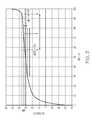
- FIG. 2is a plot of the open circuit voltage of a LiFePO 4 battery as a function of its state of charge
- FIG. 3shows a method for calculating cell capacities for a vehicle battery pack, according to an aspect of the present invention
- FIG. 4is a plot of a cell capacity distribution, according to an aspect of the present invention.
- FIG. 5is a detailed schematic illustration of the vehicle of FIG. 1 , according to an aspect of the present invention.
- FIG. 6is a detailed schematic illustration of the battery control module of FIG. 5 , according to an aspect of the present invention.
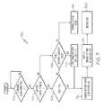
- FIG. 7is a flow diagram of a method for charging a vehicle battery pack, according to an aspect of the present invention.
- present techniques to determine battery capacitiesfocus on the pack-level and fail to account for variations in the individual cells.
- Capacity estimations at the cell levelallows for more information about the health of the battery to be determined, since underperforming or defective cells can be identified.
- identification of underperforming or defective cellsallows for corrective measures to be taken by regulating the charging and discharging of the individual cells.
- Vehicle 100includes battery pack 102 which provides electrical power to propel vehicle 100 using either a hybrid-electric or a fully-electric propulsion system.
- Battery pack 102may include multiple battery cells, modules, or a collection of discrete batteries working in conjunction to provide propulsion power to vehicle 100 .
- Vehicle 100also includes vehicle controller 104 .
- Vehicle controller 104is operatively connected to battery pack 102 and provides monitoring and control over the operation of battery pack 102 .
- Vehicle controller 104may also monitor or control one or more other functions of the vehicle.
- vehicle controller 104may provide information about the operational state of battery pack 102 to an electronic display within vehicle 100 to convey the information to the vehicle's driver.
- Vehicle controller 104may also provide control over other systems of vehicle 100 .
- vehicle controller 104may control the operations of the engine, the electrical system, or the exhaust system of vehicle 100 .
- Vehicle controller 104may be a processing circuit that includes any number of hardware and software components.
- vehicle controller 104may include a microprocessor, an application-specific integrated circuit (ASIC), or a field-programmable gate array (FPGA).
- Vehicle controller 104may also include machine instructions stored within a memory device in vehicle controller 104 which are capable of implementing one or more monitoring or control functions when executed by a processor in vehicle controller 104 .
- vehicle controller 104may include one or more memory devices such as a RAM, ROM, EEPROM, flash memory, CD-ROM, DVD-ROM, or any other non-transitory memory capable of storing the machine instructions for vehicle controller 104 .
- the actual capacity of battery pack 102denotes for a full battery how much current can be drawn from battery pack 102 , and for how long, before battery pack 102 is depleted.
- the capacity of battery pack 102may be determined using a charge count (e.g., from current measurements) over the course of time, in combination with SOC measurements.
- a battery capacityis measured in Ampere-hours (Ah) and standardized to a period of one hour. For example, a battery having a capacity of 20 Ah could be expected to provide twenty Ampere of current for one hour, before the battery is depleted. In effect, battery capacity is a measure of charge, since current is defined as:
- IQ t
- Ithe electrical current (measured in Amperes)
- Qan amount of charge (measured in Coulombs)
- a battery's capacitycan be determined using a charge count. For example, current measurements can be used to track the amount of charge into and out of battery pack 102 . Integration of the current measurements over a span of time gives to the amount of charge that has either entered the battery or left the battery during that span of time. Such a technique is sometimes referred to as a “Coulomb-counting” technique. By way of analogy only, this is somewhat similar to measuring how many gallons of gasoline have been added or depleted from a traditional fuel tank.
- SOC of battery pack 102If the SOC of battery pack 102 is also available, it can be used with the charge count to determine the actual capacity of battery pack 102 using:
- battery pack 102changes from 100% (e.g., SOC 1 ) to 95% (e.g., SOC 2 ) over the course of an hour, and the amount of charge that has left the battery in this time (e.g., Q) is equal to 3600 Coulombs, battery pack 102 has provided one Ampere of current in that hour and has lost 5% of its charge. In such a case, this is equivalent to battery pack 102 having a capacity of 20 Ah, since it would take 20 hours to fully deplete battery pack 102 at this rate.
- One technique to estimate the SOC of battery pack 102is by using a voltage-based strategy.
- the SOC of a batteryis related to its open-circuit voltage. This means that voltage measurements of battery pack 102 can be used to estimate its SOC, current measurements can be used for a charge count, and the SOC values and charge count can be used to determine the actual capacity of battery pack 102 .
- FIG. 2a plot of the open circuit voltage for a LiFeO 4 battery is shown as a function of the battery's SOC.
- the open circuit voltage for the batterychanges very little, leading to potential error in any SOC estimations based on voltage measurements of the battery.
- the tolerance of the voltage sensor providing the measurementsmay contribute to the overall uncertainty of the actual voltage of the battery.
- the voltage-SOC relationshipis also dependent on the temperature of the battery, the rest time for the battery (e.g., when the battery is not providing or receiving charge), and the diffusion constant of the battery.
- the threshold valuesmay define the range of voltage values that correspond to the relatively flat portion of a voltage-SOC characteristic. For example, a lower threshold of 3.0 volts and an upper threshold of 3.4 volts would minimize the effects of uncertainty of the voltage reading (e.g., due to the voltage sensor's tolerance, etc.) on the SOC estimate. In another example, a lower threshold of an SOC of 35% may be used.
- a method 300 for determining cell capacitiesis shown, according to an exemplary embodiment. Determining capacities at the cell level of a battery pack allows more information about the battery pack to be obtained. In some embodiments, cell capacities can be used to diagnose problematic cells, to compute a capacity distribution for the battery pack, and/or for cell balancing. In addition, the achievable accuracy may be greater when capacities are determined at the cell level, rather than at the battery pack level.
- a determinationmay be made as to whether the SOC of the battery pack is low and its rest time is high.
- a voltage-based strategymay be used to estimate the SOC of the battery pack and a voltage measurement for the battery pack compared to a lower threshold value. If the voltage measurement is below the lower threshold value, the SOC of the battery pack is also low. Since the rest time of the battery pack also affects the accuracy of an SOC estimation, a rest timer may be used to determine how long the battery pack has been at rest (e.g., the battery is not receiving or supplying power). The rest time determined by the timer may then be compared to a time threshold value, to determine if the rest time is sufficiently high enough to overcome the effects of diffusion on the battery pack. If the SOC of the battery pack is not low, or if its rest time is not long enough to overcome the effects of diffusion, the calculation of the cell capacities may be delayed until these conditions are met.
- SOC values for the individual cells of the battery packmay be determined.
- a voltage-based strategymay be used to determine the SOC estimations for the individual cells. Voltage measurements taken at the individual cells may be compared against voltage-SOC characteristics for the cells stored in a memory or lookup table to determine the individual cell capacities. Since the SOC of the battery pack is low (e.g., its voltage is below a lower threshold value), the accuracy of the SOC estimations for the individual cells is also increased.
- a charge countmay be initiated and started when the SOC of the battery pack is low and its rest time is high.
- the charge countmay be determined by taking current measurements at the battery pack and multiplying by a time differential. For example, the following equation may be used in such embodiments:
- Q i + 1Q i + I i + 1 * ⁇ ⁇ ⁇ t 3600
- Q i+1the latest charge count
- Q ithe previous charge count and may be initialized to zero for Q 0
- I i+1the latest current measurement
- ⁇ tthe change in time between current measurements.
- the charge countmay also be directly converted to Ampere-hours by dividing by 3600, since 1 Ampere-hour is equal to 3600 Coulombs.
- a determinationmay be made as to whether the SOC of the battery pack is high and the rest time is also high (e.g., the SOC is above an upper threshold and the rest time is above a time threshold).
- An upper threshold valuemay be used to ensure that the effects of error due to the tolerances of the voltage sensors are minimized.
- a time thresholdmay also be used to ensure that the effects of diffusion are also minimized.
- the vehicle battery packmay be charged as part of its normal charging procedures to increase the SOC of the battery pack (e.g., a driver plugs the vehicle into a wall socket, the engine recaptures breaking energy as electricity, etc.).
- the rest timemay also be part of the normal use of the vehicle (e.g., the vehicle is not running).
- the charge countmay be stopped when the SOC of the battery pack is high and its rest time is also high. As the battery pack is charged, its SOC also increases.
- an upper threshold valuemay be used to define when its SOC is high enough to reduce the effects of sensor tolerances on the SOC estimations.
- the chargingmay be stopped when the SOC reaches the upper threshold value and the battery may be rested for a period of time to reduce the effects of diffusion on SOC estimations.
- a time threshold valuemay be used that is based on the diffusion time constant for the battery pack.
- SOC values for the individual cellsmay be determined when the SOC of the battery pack is high and its rest time is high. Similar to the cell SOC values determined in step 304 , voltage measurements may be taken at the individual cells and compared to a voltage-SOC characteristic to estimate the SOC values, according to some embodiments. Since the voltage-SOC characteristic of certain batteries (e.g., lithium ion batteries, etc.) is relatively flat in the midrange for the SOC values, continuing the charge count until the voltage and corresponding SOC estimation are above an upper threshold value improves accuracy by minimizing the effects of sensor tolerances, etc.
- batteriese.g., lithium ion batteries, etc.
- the cell SOC values determined in steps 304 and 312may be used to determine difference values.
- the difference valuesmay be the simple difference between the high and low SOC estimations for a given cell.
- a weighting factormay be applied. For example, one or both of the SOC estimations may be multiplied by a weighting factor to account for inaccuracies in the estimation process.
- the cell capacities for the individual cellsmay be calculated.
- the cell capacitiesmay be determined using a charge count for the battery pack and the difference in SOC measurements for the individual cells. For example, the following may be used to determine a cell's capacity:
- CapCell iQ chrg ⁇ ⁇ ⁇ SOC i
- CapCell icapacity of the ith cell in the battery pack
- Q chrgthe charge count
- ⁇ SOC ithe difference value for the ith cell.
- capacity error valuesmay also be determined using:
- cell_cap_error iis the cell capacity error value for the ith cell
- Q chrgis the charge count value for the battery pack
- ⁇ SOC iis the difference value for the ith cell
- SOCis the state of charge of the battery pack
- V OCis the open-circuit voltage of the battery pack
- ⁇ V OCis an error value associated with the voltage sensor that measures V OC (e.g., its tolerance, etc.).
- FIG. 4a cell capacity distribution is shown, according to an exemplary embodiment.
- the battery pack capacitywas calculated using voltage-based SOC estimates using the pack voltage and charge counting.
- a range of erroris also shown surrounding the determined battery pack capacity to denote the amount of error attributable to the tolerances of the voltage sensors used to determine the SOC estimates for the pack.
- Calculated cell capacitiesare also shown with their corresponding error ranges. Since the pack capacity cannot be higher than the lowest cell capacity, FIG. 4 also shows a systematic error, which is included in the pack capacity value.
- Knowledge about the individual cell capacitiescan be used to enhance both cell balancing techniques and diagnostic functions of the vehicle.
- cell balancing techniquesgenerally control the charging and discharging of cells.
- Knowledge of the individual cell capacities, as opposed to just the pack-level capacity,may be used to prevent the pack performance to decrease under the single cell performances.
- diagnostic functionsmay make use of the individual cell capacities to identify cells that may need to be repaired or replaced.
- diagnostic functions and cell-balancing techniquesmay be performed. Critical cells having the lowest capacities will demonstrate the lowest voltages at the lower threshold and the highest voltages at the upper threshold. This results in small error bars for their respective cells and, therefore, in a high confidence in their determined capacity values. Therefore, diagnostic functions can be performed using this information to determine whether a cell is defective.
- the maximal achievable pack capacitycorresponds to the lowest cell capacity. This will be reached, if one specific cell has the lowest voltage at the lower threshold and at the same time the highest voltage at the upper threshold. To reach this, cell balancing may be performed using the voltage information from their respective snapshot points.
- Battery pack 102includes modules 530 , which contain battery cells 532 .
- Voltage sensors 502measure the voltage of battery pack 102 , modules 530 , and/or cells 532 and provides voltage values to interface 516 of controller 104 via bus line 510 .
- Current sensors 504measures the current of battery pack 102 , modules 530 , and/or cells 532 and provides current values to interface 516 of controller 104 via bus line 512 .
- Temperature sensors 506measures the temperature of battery pack 102 , modules 530 , and/or cells 532 and provides temperature values to interface 516 of controller 104 via bus line 514 .
- Sensors 502 , 504 , and 506may be any number of sensors or configurations to measure the voltages, currents, and temperatures associated with battery pack 102 .
- temperature sensor 506may be a single temperature sensor, while voltage sensors 502 and current sensors 504 may be a combined integrated circuit that measures both voltage and current. It should be appreciated that any number of different combinations of sensors and sensor configurations may be used, without deviating from the principles or teachings of the present disclosure.
- Bus lines 510 , 512 , and 514may be any combination of hardwired or wireless connections.
- bus line 510may be a hardwired connection to provide voltage readings to controller 104
- bus line 512may be a wireless connection to provide current readings to controller 104
- bus lines 510 , 512 and 514are part of a shared data line that conveys voltage, current, and temperature values to controller 104 .
- lines 510 , 512 , and 514may include one or more intermediary circuits (e.g., other microcontrollers, signal filters, etc.) and provide an indirect connection between sensors 502 , 504 , 506 and controller 104 .
- Interface 516is configured to receive the sensor data from sensors 502 , 504 and 506 via lines 510 , 512 , and 514 .
- interface 516may include one or more wireless receivers, if any of lines 510 , 512 , or 514 are wireless connections.
- Interface 516may also include one or more wired ports, if any of lines 510 , 512 , or 514 are wired connections.
- Interface 516may also include circuitry configured to digitally sample or filter the sensor data from 502 , 504 and 506 .
- interface 516may sample the current data received from current sensors 504 via bus line 512 at discrete times (e.g., k, k+1, k+2, etc.) to produce discrete current values (e.g., I(k), I(k+1), I(k+2), etc.).
- Controller 104is shown to include processor 519 , which may be one or more processors communicatively coupled to memory 520 and interfaces 516 and 518 .
- Memory 520may be any form of memory capable of storing machine-executable instructions that implement one or more of the functions disclosed herein, when executed by processor 519 .
- memory 520may be a RAM, ROM, flash memory, hard drive, EEPROM, CD-ROM, DVD, other forms of non-transitory memory devices, or any combination of different memory devices.
- memory 520includes vehicle control module 522 , which provides control over one or more components of vehicle 100 .
- vehicle control module 522may provide control over the engine of vehicle 100 or provide status condition information (e.g., vehicle 100 is low on fuel, vehicle 100 has an estimated number of miles left to travel based on the present SOC of battery pack 102 , etc.) to one or more display devices in the interior of vehicle 100 via interface 518 .
- vehicle control module 522may also communicate with other processing circuits (e.g., an engine control unit, an on-board diagnostics system, etc.) or other sensors (e.g., a mass airflow sensor, a crankshaft position sensor, etc.) via interface 518 .
- processing circuitse.g., an engine control unit, an on-board diagnostics system, etc.
- sensorse.g., a mass airflow sensor, a crankshaft position sensor, etc.
- Interface 518may provide one or more wired or wireless connections between processor 104 and the various systems of vehicle 100 .
- interface 518may provide a wired connection between processor 104 and a dashboard display and a wireless connection between processor 104 and an on-board diagnostics system.
- interface 518may also provide a wireless connection between processor 104 and other computing systems external to vehicle 100 .
- processor 104may communicate status condition information to an external server via a cellular, WiFi, or satellite connection.
- Interface 518may also include one or more receivers configured to send and receive location information for vehicle 100 .
- interface 518may include a GPS receiver or cellular receiver that utilizes triangulation to determine the location of vehicle 100 .
- Memory 520is further shown to include battery control module 524 , which is configured to determine and store the state of charge information about battery pack 102 .
- Battery control module 524receives battery sensor data from interface 516 and utilizes the sensor data to determine the SOC and capacity values for battery pack 102 .
- Battery control module 524may receive and provide the determined SOC value to vehicle control module 522 or to other electronic devices via interface 518 .
- battery control module 524may determine that the overall SOC of battery pack 102 , based on its actual capacity, is presently at 65% and provide an indication of this to a charge gauge in the interior of vehicle 100 via interface 518 .
- Battery control module 524may also receive one or more operating parameters via interface 518 from other systems or devices.
- battery control module 524may receive data corresponding to a mapping of open-circuit voltages to SOC values for a cell of battery pack 102 . In some embodiments, battery control module 524 may also provide control over the power draw, charging, cell balancing, etc. of battery pack 102 .
- Battery control moduleincludes battery rest timer 602 , which receives sensor data from sensors 502 , 504 and/or 506 via interface 516 .
- Battery rest timer 602uses the sensor data to determine a rest time for battery pack 102 . For example, if vehicle 100 is not currently running, battery rest timer 602 may receive an indication from current sensors 504 that no current is presently entering or leaving battery pack 102 . Battery rest timer 602 may then begin one or more timing sequences to determine the length of time that battery pack 102 is not in use. In such a case, the timing sequence may continue until an indication is received from current sensors 504 that current has been detected.
- Battery rest timer 602uses the timing sequence to generate one or more battery rest values, which may be stored in parameter storage 622 .
- battery rest timer 602may determine the battery rest time using one or more parameters stored in parameter storage 622 .
- parameter storage 622may include parameters received from other electronic systems 634 that are indicative of the running state of the vehicle (e.g., the vehicle is idling, the vehicle is off, the vehicle is moving, etc.).
- parameter storage 622may receive an indication from the ignition of vehicle 100 via interface 518 whenever vehicle 100 is turned off or started and may store one or more parameters related to these events.
- SOC generator 604receives voltage, current, and temperature data from interface 516 and uses them to generate SOC values 608 .
- SOC generator 604uses a voltage-based strategy to generate SOC values 608 using one or more voltage-SOC characteristics stored in parameter storage 622 .
- voltage-SOC characteristicsmay vary depending on the amount of rest time of a battery, the temperature of the battery, the charging state of the battery (e.g., charging or discharging), etc. Different voltage-SOC characteristics may be stored in parameter storage 622 and may be retrieved by SOC generator 604 based on the sensor data received from interface 516 and a rest count from rest timer 602 .
- SOC generator 604may also retrieve an upper and a lower threshold value from parameter storage 622 to evaluate the SOC of battery pack 102 .
- the upper and lower threshold valuesmay be reference voltage values that SOC generator 604 compares to sensor data indicative of the open-circuit voltage of battery pack 102 .
- the upper and lower threshold valuesmay be reference SOC values that SOC generator 604 compares against calculated SOC values.
- SOC generator 604uses the threshold values to determine whether the SOC of battery pack 102 is above or below the thresholds, since the open-circuit voltage of battery pack 102 and its SOC are interrelated.
- SOC generator 604may also verify that the rest time received from rest timer 602 is also above a time threshold stored in parameter storage 622 .
- parameter storage 622stores one or more rest time thresholds. For example, the amount of time necessary to minimize the effects of diffusion on the SOC estimation for battery pack 102 may vary with temperature. In this case, SOC generator 604 may use the sensor data received from interface 516 and use it to retrieve a rest time threshold value from parameter storage 622 .
- SOC generator 604may use the sensor data received from interface 516 to generate SOC values 608 for one or more cells in battery pack 102 .
- SOC values 608may store a set of SOC values for the cells when the SOC of battery pack 102 is low and another set of SOC values for the cells when the SOC of battery pack 102 is high.
- SOC generator 604may also provide an indication to charge counter 606 that the SOC of battery pack 102 is above the upper threshold value or below the lower threshold value.
- charge counter 606may initialize and begin a charge count.
- charge countermay utilize sensor data from interface 516 indicative of a current of battery pack 102 and time information from rest timer 602 to determine the charge count. If charge counter 606 receives an indication from SOC generator 604 that the SOC of battery pack 102 is above the upper threshold value, it may stop the charge count and store the current count as charge count 610 .
- Difference evaluator 612may receive an indication from SOC generator 604 that the SOC of battery pack 102 is above the upper threshold value and use SOC values 608 to generate SOC difference values 614 .
- SOC values 608may contain sets of SOC values for the cells of battery pack 102 , where one set corresponds to battery pack 102 having an SOC below a lower threshold and the other set corresponds to battery pack 102 having an SOC above an upper threshold.
- SOC difference values 614are the simple differences between these sets.
- difference evaluator 612may apply a scaling or weighting to one or both SOC values.
- Cell capacity calculator 616calculates cell capacities 626 using SOC difference values 614 and charge count 610 . In some embodiments, cell capacity calculator divides charge count 610 by SOC difference values 614 to calculate cell capacities 626 . In some embodiments, cell capacities 626 may be provided to display 630 , interface devices (e.g., a touch-screen display, a speaker, or the like), or to other electronic systems (e.g., other controllers, a remote computer system, or the like) via interface 518 . Cell capacities 626 may also be used by processor 519 to correct SOC estimations provided to a driver via display 630 , interface devices 632 , or electronic systems 634 .
- cell capacities 626may also be provided to processor 519 to determine a cell capacity distribution over some or all of battery pack 102 or to cell balancer 624 for use in cell balancing.
- cell capacity calculator 616may be further configured to determine a cell capacity distribution over the entire battery pack using cell capacities 626 .
- cell capacity calculator 616may also use cell capacities 626 to determine an estimate for the overall capacity of battery pack 102 .
- the pack capacityis always lower or equal to the lowest cell capacity.
- Cell capacity calculator 616may utilize this relationship and the spread of values in cell capacities 626 to estimate the overall capacity of battery pack 102 .
- Capacity error evaluator 618uses SOC values 608 , difference values 614 , charge count 610 , and sensor data from interface 516 to generate cell capacity error values 620 . While the accuracy of cell capacities 626 may be improved by calculating their underlying SOC values 608 when the SOC of battery pack 102 is above or below threshold values, sources of error may still remain for the individual cells. In some embodiments, capacity error evaluator 618 may calculate cell capacity error values 620 using the following calculation:
- cell_cap_error iis the cell capacity error value for the ith cell
- Q chrgis the charge count value for the battery pack
- ⁇ SOC iis the difference value for the ith cell
- SOCis the state of charge of the battery pack
- V OCis the open-circuit voltage of battery pack 102
- ⁇ V OCis an error value associated with the voltage sensor that measures V OC (e.g., its tolerance, etc.).
- capacity error values 620may provide a range relative to cell capacities 626 .
- a particular cell in battery pack 102may have an actual cell capacity within a range defined by its cell capacity in cell capacities 626 and the error range defined by its error values in cell capacity error values 620 .
- capacity error evaluator 618may also use cell capacity error values 620 to identify those cells having the lowest cell capacities (e.g., those cells having the smallest cell capacity error values).
- Cell balancer 624performs cell balancing, a technique that regulates the flow of a cell balancing current to the individual cells of battery pack 102 .
- Cell balancingmay regulate the flow of a cell balancing current to and from the individual cells, in order to distribute the use of the cells by vehicle 100 more evenly. For example, as the cells in battery pack 102 age, their individual capacities may differ.
- Cell balancer 624may use cell capacities 626 and/or cell capacity error values 620 to determine which cells should be charged or discharged, the amount of charging or discharging, and for how long the cells should be charged or discharged.
- cell balancer 624may perform cell balancing to ensure that a specific cell has the lowest voltage when the SOC of the pack is low and the highest voltage when the SOC of the pack is high. In another embodiment, cell balancer 624 may perform cell balancing to minimize one or more error values in cell capacity error values 620 . In some embodiments, cell balancer 624 may also perform diagnostic functions by determining which cell capacities 626 are defective (e.g., above or below a given threshold), and providing an indication of this determination to vehicle control module 522 , display 630 , interface devices 632 , and/or other electronic systems 634 .
- Parameter storage 622may include any number of user or system defined parameters that override or control the functions of battery control module 524 .
- parametermay include parameters that control how often cell capacities 626 are calculated, how cell capacities 626 are used for diagnostic functions, or how cell balancing is performed by cell balancer 624 .
- Method 700for charging a vehicle battery pack is shown, according to an exemplary embodiment.
- Method 700may be utilized in conjunction with method 300 to determine cell capacity values as part of the charging process.
- vehicle 100may also have a charging plug to replenish the charge in battery pack 102 using a home or industrial wall socket.
- Battery control module 524may receive a signal from voltage sensors 502 or current sensors 504 that power is being provided to battery pack 102 via the charging plug. If the charging plug is determined to not be connected, further processing of method 700 may be delayed until such a time that a plug is connected. However, if a plug is connected, method 700 may proceed to step 704 for further processing.
- a battery capacity modecorresponds to an indication that the previously determined capacity of the battery pack should be updated.
- Factors that may be used to determine whether a vehicle is in a battery capacity modeinclude, but are not limited to, the length of time from the previous capacity calculation and the degree of accuracy of the previous capacity calculation.
- vehicle 100may be placed in a battery capacity mode by battery control module 524 if cell capacities 624 are two to three weeks old.
- step 706if the vehicle is in a battery capacity mode, a determination is made as to whether the SOC of the battery pack is below a lower threshold value. In some embodiments, this step may be performed in parallel or in conjunction with step 302 of method 300 .
- SOC generator 604may utilize sensor data received via interface 516 and a lower threshold value stored in parameter storage 622 to determine if the SOC of battery pack 102 is below the threshold. Because the voltage-SOC characteristics for certain batteries drop rapidly as their SOC values approach zero, the use of a lower threshold value improves the accuracy of the cell SOC estimations that are used later on to determine the capacity values.
- the parametersmay be provided from a user interface device, a remote computer system, or any other electronic device that allows such parameters to be sent to the battery control module of a vehicle.
- battery control module 524may receive a parameter from interface devices 632 (e.g., a touch screen display, a mouse, etc.) and store the parameter in parameter storage 622 .
- the battery packmay be charged normally, i.e., without determining cell capacities. Any standard charging method may be used when cell capacities are not determined.
- the battery packmay be discharged until its SOC is below a lower threshold value to ensure the accuracy of the SOC measurements for the cells.
- cell balancer 624may additionally be configured to discharge any number of cells or modules of battery pack 102 .
- the discharged energymay be stored in a low voltage battery and provided back to battery pack 102 during the next charging cycle. In other embodiments, the discharged energy may be used to thermally condition battery pack 102 .
- the battery packmay be charged with a certain amount of amps and with a specified Ampere-hour throughput. Because voltage-SOC characteristic curves experience hysteresis (e.g., the voltage-SOC characteristic curve differs for charging and discharging), controlling the current and throughput to the battery pack allows for the corresponding voltage-SOC characteristic to be selected.
- parameter storage 622may store different voltage-SOC characteristics that may be selected by SOC generator 504 based on how battery pack 102 is charged. Step 712 allows battery pack 102 to be charged until a preferred region of the selected voltage-SOC characteristic is reached.
- step 714once the battery has been charged to a desired point on the voltage-SOC characteristic curve, charging of the battery may be halted for a specified rest time. Allowing the battery pack to be in a state of rest (e.g., not charging or discharging) minimizes dynamic voltage effects caused by diffusion.
- the amount of rest time necessaryis battery specific and depends on cell chemistry (e.g., their diffusion constants, etc.) and their temperatures.
- SOC generator 604may retrieve cell chemistry information from parameter storage 622 and temperature data from temperature sensors 506 to determine an appropriate rest time threshold.
- method 300is performed after step 714 to determine cell capacity values to reduce potential sources of error. In other embodiments, method 300 may be performed in conjunction with other charging or discharging methods instead of, or in addition to, charging method 700 .
- a processing circuitmay be an ASIC, a specific-use processor, or any existing computer processor.
- One or more steps or functions in the present disclosuremay also be accomplished using non-transitory, machine-readable instructions and data structures stored on machine-readable media.
- machine-readable mediamay comprise a floppy disc, CD-ROM, DVD-ROM, RAM, EEPROM, flash memory, or any other medium capable of storing the machine-executable instructions and data structures and capable of being accessed by a computer or other electronic device having a processing circuit.
Landscapes
- Engineering & Computer Science (AREA)
- Power Engineering (AREA)
- Life Sciences & Earth Sciences (AREA)
- Sustainable Development (AREA)
- Sustainable Energy (AREA)
- Transportation (AREA)
- Mechanical Engineering (AREA)
- Physics & Mathematics (AREA)
- General Physics & Mathematics (AREA)
- Secondary Cells (AREA)
- Charge And Discharge Circuits For Batteries Or The Like (AREA)
- Tests Of Electric Status Of Batteries (AREA)
Abstract
Description
where I is the electrical current (measured in Amperes), Q is an amount of charge (measured in Coulombs), and t is an amount of time. Multiplying both sides by an amount of time gives:
I*t=Q
Therefore, battery capacity, measured in Ampere-hours (e.g., current*time), is equivalently a measure of charge and can also be denoted in Coulombs.
where SOC1is an initial SOC estimate, SOC2is a final SOC estimate, and Q is the charge count. By way of analogy, this is similar to determining the change in how “full” a traditional fuel tank is over a period of time and dividing it by how many gallons have left the tank during this time. For example and not a limitation, if the SOC of
where Qi+1is the latest charge count, Qiis the previous charge count and may be initialized to zero for Q0, Ii+1is the latest current measurement, and Δt is the change in time between current measurements. The charge count may also be directly converted to Ampere-hours by dividing by 3600, since 1 Ampere-hour is equal to 3600 Coulombs.
where CapCelliis capacity of the ith cell in the battery pack, Qchrgis the charge count, and ΔSOCiis the difference value for the ith cell.
where cell_cap_erroriis the cell capacity error value for the ith cell, Qchrgis the charge count value for the battery pack, ΔSOCiis the difference value for the ith cell, SOC is the state of charge of the battery pack, VOCis the open-circuit voltage of the battery pack, and ΔVOCis an error value associated with the voltage sensor that measures VOC(e.g., its tolerance, etc.).
where cell_cap_erroriis the cell capacity error value for the ith cell, Qchrgis the charge count value for the battery pack, ΔSOCiis the difference value for the ith cell, SOC is the state of charge of the battery pack, VOCis the open-circuit voltage of
Claims (17)
Priority Applications (3)
| Application Number | Priority Date | Filing Date | Title |
|---|---|---|---|
| US13/107,171US9037426B2 (en) | 2011-05-13 | 2011-05-13 | Systems and methods for determining cell capacity values in a multi-cell battery |
| DE102012207815.0ADE102012207815B4 (en) | 2011-05-13 | 2012-05-10 | SYSTEMS AND METHODS FOR DETERMINING CELL CAPACITY VALUES IN A BATTERY WITH MANY CELLS |
| CN201210145277.4ACN102778651B (en) | 2011-05-13 | 2012-05-11 | Determine the system and method for battery cell capacity value in many battery |
Applications Claiming Priority (1)
| Application Number | Priority Date | Filing Date | Title |
|---|---|---|---|
| US13/107,171US9037426B2 (en) | 2011-05-13 | 2011-05-13 | Systems and methods for determining cell capacity values in a multi-cell battery |
Publications (2)
| Publication Number | Publication Date |
|---|---|
| US20120290234A1 US20120290234A1 (en) | 2012-11-15 |
| US9037426B2true US9037426B2 (en) | 2015-05-19 |
Family
ID=47070734
Family Applications (1)
| Application Number | Title | Priority Date | Filing Date |
|---|---|---|---|
| US13/107,171Expired - Fee RelatedUS9037426B2 (en) | 2011-05-13 | 2011-05-13 | Systems and methods for determining cell capacity values in a multi-cell battery |
Country Status (3)
| Country | Link |
|---|---|
| US (1) | US9037426B2 (en) |
| CN (1) | CN102778651B (en) |
| DE (1) | DE102012207815B4 (en) |
Cited By (20)
| Publication number | Priority date | Publication date | Assignee | Title |
|---|---|---|---|---|
| US20140340045A1 (en)* | 2012-01-26 | 2014-11-20 | Calsonic Kansei Corporation | Apparatus for battery state estimation |
| US20160011273A1 (en)* | 2012-09-18 | 2016-01-14 | Apple Inc. | Method and apparatus for determining a capacity of a battery |
| US20170131365A1 (en)* | 2012-12-27 | 2017-05-11 | Duracell U.S. Operations, Inc. | Remote sensing of remaining battery capacity using on-battery circuitry |
| US10151802B2 (en) | 2016-11-01 | 2018-12-11 | Duracell U.S. Operations, Inc. | Reusable battery indicator with electrical lock and key |
| US10297875B2 (en) | 2015-09-01 | 2019-05-21 | Duracell U.S. Operations, Inc. | Battery including an on-cell indicator |
| US10416309B2 (en) | 2013-06-21 | 2019-09-17 | Duracell U.S. Operations, Inc. | Systems and methods for remotely determining a battery characteristic |
| US20190339332A1 (en)* | 2017-01-13 | 2019-11-07 | Denso Corporation | Battery pack and power supply system |
| US10483634B2 (en) | 2016-11-01 | 2019-11-19 | Duracell U.S. Operations, Inc. | Positive battery terminal antenna ground plane |
| US10608293B2 (en) | 2016-11-01 | 2020-03-31 | Duracell U.S. Operations, Inc. | Dual sided reusable battery indicator |
| US10818979B2 (en) | 2016-11-01 | 2020-10-27 | Duracell U.S. Operations, Inc. | Single sided reusable battery indicator |
| US10916850B2 (en) | 2013-05-23 | 2021-02-09 | Duracell U.S. Operations, Inc. | Omni-directional antenna for a cylindrical body |
| US10964980B2 (en) | 2014-05-30 | 2021-03-30 | Duracell U.S. Operations, Inc. | Indicator circuit decoupled from a ground plane |
| US10988047B2 (en)* | 2018-09-13 | 2021-04-27 | Bayerische Motoren Werke Aktiengesellschaft | Method for determining a capacity of a battery cell, evaluation device, monitoring apparatus, high-voltage battery and motor vehicle |
| US11024891B2 (en) | 2016-11-01 | 2021-06-01 | Duracell U.S. Operations, Inc. | Reusable battery indicator with lock and key mechanism |
| US11034257B2 (en)* | 2019-01-11 | 2021-06-15 | GM Global Technology Operations LLC | Method and system for estimating remaining battery pack energy using cell-group state of charge spread |
| US11209491B2 (en)* | 2018-12-06 | 2021-12-28 | Stl Technology Co., Ltd. | Estimation method for state of charge of battery |
| US20220276310A1 (en)* | 2020-07-13 | 2022-09-01 | Contemporary Amperex Technology Co., Limited | Method, apparatus, and computer storage medium for identifying cell |
| US11437827B2 (en)* | 2016-03-01 | 2022-09-06 | Volvo Truck Corporation | Control of a relatively low current fed to a battery pack |
| US20220302729A1 (en)* | 2019-11-08 | 2022-09-22 | Hewlett-Packard Development Company, L.P. | Charge determination |
| US11837754B2 (en) | 2020-12-30 | 2023-12-05 | Duracell U.S. Operations, Inc. | Magnetic battery cell connection mechanism |
Families Citing this family (72)
| Publication number | Priority date | Publication date | Assignee | Title |
|---|---|---|---|---|
| US20120013189A1 (en)* | 2010-07-15 | 2012-01-19 | Vercingetorix, Llc | battery management system |
| US20120319653A1 (en)* | 2011-06-15 | 2012-12-20 | Ajith Kuttannair Kumar | System and method for rechargeable battery |
| JP5684172B2 (en)* | 2012-03-03 | 2015-03-11 | 古河電気工業株式会社 | Secondary battery state detection device and secondary battery state detection method |
| JP5803767B2 (en)* | 2012-03-22 | 2015-11-04 | 株式会社デンソー | Secondary battery charge equivalent amount calculation device |
| US10003062B2 (en) | 2012-09-14 | 2018-06-19 | Lenovo Enterprise Solutions (Singapore) Pte. Ltd. | Modular battery cover |
| US9472959B2 (en)* | 2012-11-30 | 2016-10-18 | GM Global Technology Operations LLC | Systems and methods for balancing a vehicle battery system |
| US9128159B2 (en)* | 2012-12-12 | 2015-09-08 | GM Global Technology Operations LLC | Plug-in charge capacity estimation method for lithium iron-phosphate batteries |
| US20140214346A1 (en)* | 2013-01-25 | 2014-07-31 | Cummins Inc. | Adaptive available power estimation for high voltage lithium ion battery |
| US9368979B2 (en) | 2013-03-15 | 2016-06-14 | O2Micro Inc | System and methods for battery balancing |
| DE102013206896A1 (en)* | 2013-04-17 | 2014-10-23 | Siemens Aktiengesellschaft | Method for determining the state of charge of a battery |
| DE102013214292B4 (en)* | 2013-07-22 | 2018-12-27 | Siemens Aktiengesellschaft | Charge state detection of electrochemical storage |
| DE102013217451A1 (en) | 2013-09-02 | 2015-03-05 | Robert Bosch Gmbh | Method for data transmission in a battery management system |
| DE102013217752B4 (en)* | 2013-09-05 | 2015-12-03 | Continental Automotive Gmbh | Determining the capacity of a battery |
| FR3010797B1 (en)* | 2013-09-18 | 2015-10-02 | Renault Sa | METHOD FOR ESTIMATING THE AGING OF A BATTERY CELL OF ACCUMULATORS |
| CN103487760B (en)* | 2013-09-27 | 2015-12-23 | 湖南南车时代电动汽车股份有限公司 | A kind of decision method of battery health degree |
| DE102013221589A1 (en) | 2013-10-24 | 2015-04-30 | Robert Bosch Gmbh | Method for determining the capacity of a battery cell |
| CN104600383B (en)* | 2013-10-30 | 2017-02-08 | 北汽福田汽车股份有限公司 | Battery pack electric quantity equalization method and apparatus thereof |
| CN104714181B (en)* | 2013-12-11 | 2017-10-27 | 广州汽车集团股份有限公司 | It is a kind of to obtain voltage and the method and system of battery charge state relation |
| DE102014200619A1 (en)* | 2014-01-15 | 2015-07-16 | Robert Bosch Gmbh | Method for charge state compensation of a battery |
| DE102014200669A1 (en)* | 2014-01-16 | 2015-07-16 | Robert Bosch Gmbh | Method for determining quantities for battery management functions |
| KR101551062B1 (en)* | 2014-02-18 | 2015-09-07 | 현대자동차주식회사 | Apparatus and Method for diagnosing defect of battery cell |
| US9533597B2 (en)* | 2014-03-05 | 2017-01-03 | Ford Global Technologies, Llc | Parameter identification offloading using cloud computing resources |
| US9446678B2 (en) | 2014-03-05 | 2016-09-20 | Ford Global Technologies, Llc | Battery model with robustness to cloud-specific communication issues |
| US9594121B2 (en)* | 2014-04-04 | 2017-03-14 | GM Global Technology Operations LLC | Systems and methods for estimating battery pack capacity |
| US9583792B2 (en) | 2014-06-11 | 2017-02-28 | Lenovo Enterprise Solutions (Singapore) Pte. Ltd. | Dynamically configurable auto-healing battery |
| US9535129B2 (en)* | 2014-06-17 | 2017-01-03 | GM Global Technology Operations LLC | Systems and methods for estimating battery pack capacity during charge sustaining use |
| US9438048B2 (en) | 2014-06-20 | 2016-09-06 | Lenovo Enterprise Solutions (Singapore) Pte. Ltd. | Modular battery cell architecture and control method |
| US10074996B2 (en) | 2014-08-29 | 2018-09-11 | The Regents Of The University Of Michigan | Bulk force in a battery pack and its application to state of charge estimation |
| FR3029298B1 (en)* | 2014-11-28 | 2016-12-30 | Renault Sa | AUTOMATIC METHOD OF ESTIMATING THE CHARGING STATE OF A CELL OF A BATTERY |
| KR102399722B1 (en)* | 2014-12-29 | 2022-05-19 | 삼성전자주식회사 | Method and apparatus for estimating current |
| CN104569845B (en)* | 2014-12-31 | 2017-11-07 | 普天新能源车辆技术有限公司 | A kind of waste and old dynamic lithium battery capacity check method and device |
| US9557387B2 (en) | 2015-02-10 | 2017-01-31 | Lenovo Enterprise Solutions (Singapore) Pte. Ltd. | Testing individual cells within multi-cell battery applications |
| KR102424528B1 (en)* | 2015-06-11 | 2022-07-25 | 삼성전자주식회사 | Method and device to estimate state of battery |
| CN105116338B (en)* | 2015-07-15 | 2017-12-05 | 盐城工学院 | A kind of parallel connection type battery system modeling method based on SOC compensators |
| SE540603C2 (en)* | 2015-11-05 | 2018-10-02 | Ctek Sweden Ab | A system and a method for determining the state of charge of a battery |
| FR3045216B1 (en)* | 2015-12-14 | 2019-10-25 | Psa Automobiles Sa. | BATTERY COMPRISING A PLURALITY OF CELLS IN SERIES |
| DE102016101031B4 (en)* | 2016-01-21 | 2019-03-21 | Tesvolt Gmbh | Method and device for determining a reduced capacity of a cell module, battery system and computer program |
| US20170219657A1 (en)* | 2016-01-28 | 2017-08-03 | Bae Systems Controls Inc. | Online battery capacity estimation utilizing passive balancing |
| US10114079B2 (en)* | 2016-02-24 | 2018-10-30 | Ford Global Technologies, Llc | System and method for identifying vehicle battery decay |
| US11415630B2 (en)* | 2016-02-29 | 2022-08-16 | University Of Hawaii | Methods and apparatus for updating a fuel gauge and estimating state of health of an energy storage cell |
| CN105548912A (en)* | 2016-03-03 | 2016-05-04 | 合肥国轩高科动力能源有限公司 | Battery state of charge calibration method based on battery aging characteristics |
| CN105891721A (en)* | 2016-04-01 | 2016-08-24 | 深圳市清友能源技术有限公司 | SOC test method and SOC test device for battery management system |
| US10446885B2 (en) | 2016-05-13 | 2019-10-15 | Schumacher Electric Corporation | Battery charger with battery state detection |
| US10899247B2 (en)* | 2016-06-08 | 2021-01-26 | Ford Global Technologies, Llc | System and method for online vehicle battery capacity diagnosis |
| KR102634815B1 (en)* | 2016-11-22 | 2024-02-07 | 삼성전자주식회사 | Method and apparatus for estimating state of battery based on error correction |
| US11124087B2 (en) | 2016-12-01 | 2021-09-21 | Volvo Truck Corporation | System and a method for selecting energy storage cells for balancing of an electrical energy storage pack |
| US10322688B2 (en) | 2016-12-30 | 2019-06-18 | Textron Innovations Inc. | Controlling electrical access to a lithium battery on a utility vehicle |
| CN106953380A (en)* | 2017-03-30 | 2017-07-14 | 惠州市蓝微新源技术有限公司 | A kind of method of controlling switch of battery management system relay |
| JP7032110B2 (en)* | 2017-11-21 | 2022-03-08 | トヨタ自動車株式会社 | Exchange charge setting device and exchange charge setting system |
| CN108287315B (en)* | 2018-01-12 | 2021-01-22 | 北京新能源汽车股份有限公司 | Power battery running state monitoring method and device and electric automobile |
| US20190308630A1 (en)* | 2018-04-10 | 2019-10-10 | GM Global Technology Operations LLC | Battery state estimation based on open circuit voltage and calibrated data |
| CN108717164B (en)* | 2018-04-11 | 2022-07-01 | 中国电力科学研究院有限公司 | SOC calibration method and system for battery |
| CN108845267B (en)* | 2018-06-29 | 2021-06-25 | 上海科列新能源技术有限公司 | Data processing method and device for power battery |
| CN109116242B (en)* | 2018-06-29 | 2021-03-02 | 上海科列新能源技术有限公司 | Data processing method and device for power battery |
| US11904724B2 (en) | 2018-09-17 | 2024-02-20 | Volvo Truck Corporation | Method for estimating an operating parameter of a battery cell in a vehicle |
| US20200249279A1 (en)* | 2019-02-06 | 2020-08-06 | GM Global Technology Operations LLC | Method and diagnostic service tool for a battery pack |
| CN110109018A (en)* | 2019-04-30 | 2019-08-09 | 清华大学 | Data drawing list generation method and battery pack maintenance method |
| DE102020202366A1 (en) | 2020-02-25 | 2021-08-26 | Robert Bosch Gesellschaft mit beschränkter Haftung | Method for operating a battery pack and battery pack |
| KR102630834B1 (en)* | 2020-05-15 | 2024-01-30 | 주식회사 엘지에너지솔루션 | Apparatus and method for diagnosing battery |
| CN111896878A (en)* | 2020-08-10 | 2020-11-06 | 陈永强 | On-line discrimination method for open-circuit batteries in battery pack |
| CN112327176B (en)* | 2020-10-16 | 2024-03-19 | 欣旺达动力科技股份有限公司 | Battery performance detection method, system and storage medium |
| CN112260372B (en)* | 2020-12-23 | 2021-04-27 | 江苏时代新能源科技有限公司 | Battery equalization method and device and battery management system |
| CN113109719B (en)* | 2021-04-16 | 2023-05-05 | 厦门金龙联合汽车工业有限公司 | Peak position and peak intensity identification method for capacity differential multimodal curve of big data system |
| CN113376526A (en)* | 2021-04-29 | 2021-09-10 | 广汽三菱汽车有限公司 | Automobile battery capacity prediction method, life prediction method, device and storage medium |
| CN113589188A (en)* | 2021-08-12 | 2021-11-02 | 湖北亿纬动力有限公司 | Battery life evaluation method, device and system |
| CN114740366A (en)* | 2022-05-07 | 2022-07-12 | 东软睿驰汽车技术(沈阳)有限公司 | Method and device for determining SOC (state of charge) of battery cell in battery pack |
| US11664670B1 (en)* | 2022-08-21 | 2023-05-30 | Element Energy, Inc. | Methods and systems for updating state of charge estimates of individual cells in battery packs |
| CN116014274B (en)* | 2022-12-09 | 2025-03-21 | 东风汽车集团股份有限公司 | A battery capacity calculation method, device, equipment and readable storage medium |
| KR102841208B1 (en)* | 2023-01-16 | 2025-07-31 | 한화솔루션 주식회사 | Monitoring device for energy storage system and monitoring method thereof |
| FR3148649B1 (en)* | 2023-05-11 | 2025-05-23 | Accumulateurs Fixes | Method for determining a contribution to a measurement deviation of the state of charge of an electrochemical battery element and associated method and devices |
| US20250076391A1 (en)* | 2023-09-05 | 2025-03-06 | GM Global Technology Operations LLC | Dynamic target state of charge for hybrid vehicle capacity estimation |
| CN117445740B (en)* | 2023-10-31 | 2024-10-22 | 上汽通用五菱汽车股份有限公司 | Charging method, device, system, controller and storage medium |
Citations (15)
| Publication number | Priority date | Publication date | Assignee | Title |
|---|---|---|---|---|
| CN1415973A (en) | 2001-10-30 | 2003-05-07 | 雅马哈发动机株式会社 | Bottery capacity control method and its device and capacity controller for battery of vehicle power |
| US6639385B2 (en) | 2001-08-07 | 2003-10-28 | General Motors Corporation | State of charge method and apparatus |
| US6700350B2 (en)* | 2002-05-30 | 2004-03-02 | Texas Instruments Incorporated | Method and apparatus for controlling charge balance among cells while charging a battery array |
| US7136762B2 (en)* | 2004-01-14 | 2006-11-14 | Fuji Jukogyo Kabushiki Kaisha | System for calculating remaining capacity of energy storage device |
| US7193392B2 (en)* | 2002-11-25 | 2007-03-20 | Tiax Llc | System and method for determining and balancing state of charge among series connected electrical energy storage units |
| US20070080662A1 (en)* | 2005-10-11 | 2007-04-12 | Deping Wu | Universal battery module and controller therefor |
| US20100052614A1 (en)* | 2008-09-03 | 2010-03-04 | Modalis Engineering, Inc. | Systems, apparatus and methods for battery charge management |
| US7768233B2 (en)* | 2007-10-04 | 2010-08-03 | Gm Global Technology Operations, Inc. | Dynamically adaptive method for determining the state of charge of a battery |
| CN101917038A (en) | 2010-08-05 | 2010-12-15 | 惠州市亿能电子有限公司 | Charge balancing control method of power battery pack |
| US7928691B2 (en)* | 2004-11-10 | 2011-04-19 | EaglePicher Technologies | Method and system for cell equalization with isolated charging sources |
| US20110130986A1 (en)* | 2009-12-02 | 2011-06-02 | American Electric Vehicles, Inc. | System and Method For Maximizing a Battery Pack Total Energy Metric |
| US20110221400A1 (en)* | 2008-11-21 | 2011-09-15 | Honda Motor Co., Ltd | Charge controller |
| US20120133332A1 (en)* | 2009-07-31 | 2012-05-31 | Honda Motor Co., Ltd. | Storage capacity management system |
| US20130320989A1 (en)* | 2011-03-07 | 2013-12-05 | Hitachi, Ltd. | Battery state estimation method and battery control system |
| US20140336964A1 (en)* | 2011-04-01 | 2014-11-13 | Toyota Jidosha Kabushiki Kaisha | Method for determining remaining lifetime |
Family Cites Families (5)
| Publication number | Priority date | Publication date | Assignee | Title |
|---|---|---|---|---|
| JP4649101B2 (en)* | 2003-09-10 | 2011-03-09 | 株式会社日本自動車部品総合研究所 | Secondary battery status detection device and status detection method |
| EP1752780B1 (en) | 2004-04-06 | 2017-06-07 | Cobasys, LLC | Battery state of charge estimator |
| US7525285B2 (en)* | 2004-11-11 | 2009-04-28 | Lg Chem, Ltd. | Method and system for cell equalization using state of charge |
| WO2008095315A1 (en) | 2007-02-09 | 2008-08-14 | Advanced Lithium Power Inc. | Battery management system |
| CN101813754B (en)* | 2010-04-19 | 2012-09-05 | 清华大学 | State estimating method for automobile start illumination type lead-acid storage battery |
- 2011
- 2011-05-13USUS13/107,171patent/US9037426B2/ennot_activeExpired - Fee Related
- 2012
- 2012-05-10DEDE102012207815.0Apatent/DE102012207815B4/ennot_activeExpired - Fee Related
- 2012-05-11CNCN201210145277.4Apatent/CN102778651B/ennot_activeExpired - Fee Related
Patent Citations (15)
| Publication number | Priority date | Publication date | Assignee | Title |
|---|---|---|---|---|
| US6639385B2 (en) | 2001-08-07 | 2003-10-28 | General Motors Corporation | State of charge method and apparatus |
| CN1415973A (en) | 2001-10-30 | 2003-05-07 | 雅马哈发动机株式会社 | Bottery capacity control method and its device and capacity controller for battery of vehicle power |
| US6700350B2 (en)* | 2002-05-30 | 2004-03-02 | Texas Instruments Incorporated | Method and apparatus for controlling charge balance among cells while charging a battery array |
| US7193392B2 (en)* | 2002-11-25 | 2007-03-20 | Tiax Llc | System and method for determining and balancing state of charge among series connected electrical energy storage units |
| US7136762B2 (en)* | 2004-01-14 | 2006-11-14 | Fuji Jukogyo Kabushiki Kaisha | System for calculating remaining capacity of energy storage device |
| US7928691B2 (en)* | 2004-11-10 | 2011-04-19 | EaglePicher Technologies | Method and system for cell equalization with isolated charging sources |
| US20070080662A1 (en)* | 2005-10-11 | 2007-04-12 | Deping Wu | Universal battery module and controller therefor |
| US7768233B2 (en)* | 2007-10-04 | 2010-08-03 | Gm Global Technology Operations, Inc. | Dynamically adaptive method for determining the state of charge of a battery |
| US20100052614A1 (en)* | 2008-09-03 | 2010-03-04 | Modalis Engineering, Inc. | Systems, apparatus and methods for battery charge management |
| US20110221400A1 (en)* | 2008-11-21 | 2011-09-15 | Honda Motor Co., Ltd | Charge controller |
| US20120133332A1 (en)* | 2009-07-31 | 2012-05-31 | Honda Motor Co., Ltd. | Storage capacity management system |
| US20110130986A1 (en)* | 2009-12-02 | 2011-06-02 | American Electric Vehicles, Inc. | System and Method For Maximizing a Battery Pack Total Energy Metric |
| CN101917038A (en) | 2010-08-05 | 2010-12-15 | 惠州市亿能电子有限公司 | Charge balancing control method of power battery pack |
| US20130320989A1 (en)* | 2011-03-07 | 2013-12-05 | Hitachi, Ltd. | Battery state estimation method and battery control system |
| US20140336964A1 (en)* | 2011-04-01 | 2014-11-13 | Toyota Jidosha Kabushiki Kaisha | Method for determining remaining lifetime |
Non-Patent Citations (8)
| Title |
|---|
| http://homepages.which.net/~paul.hills/Batteries/BatteriesBody.html, Batteries V2.07, Jul. 5, 2004, printed May 12, 2011, pp. 1-18. |
| http://homepages.which.net/˜paul.hills/Batteries/BatteriesBody.html, Batteries V2.07, Jul. 5, 2004, printed May 12, 2011, pp. 1-18. |
| http://www.liionbnns.conniphp/wp-soc-estimate.php, White Paper-Estimating the State of Charge of Li-Ion batteries, pp. 1-7, May 12, 2011. |
| http://www.liionbnns.conniphp/wp—soc—estimate.php, White Paper—Estimating the State of Charge of Li-Ion batteries, pp. 1-7, May 12, 2011. |
| Internet Web Site: http://homepages.which.net/~paul.hills/Batteries/BatteriesBody.html; accessed May 12, 2011. |
| Internet Web Site: http://homepages.which.net/˜paul.hills/Batteries/BatteriesBody.html; accessed May 12, 2011. |
| Internet Web Site: http://liionbms.com/php/wp-soc-estimate.php; accessed May 12, 2011. |
| Internet Web Site: http://liionbms.com/php/wp—soc—estimate.php; accessed May 12, 2011. |
Cited By (34)
| Publication number | Priority date | Publication date | Assignee | Title |
|---|---|---|---|---|
| US20140340045A1 (en)* | 2012-01-26 | 2014-11-20 | Calsonic Kansei Corporation | Apparatus for battery state estimation |
| US20160011273A1 (en)* | 2012-09-18 | 2016-01-14 | Apple Inc. | Method and apparatus for determining a capacity of a battery |
| US9651628B2 (en)* | 2012-09-18 | 2017-05-16 | Apple Inc. | Method and apparatus for determining a capacity of a battery |
| US20170131365A1 (en)* | 2012-12-27 | 2017-05-11 | Duracell U.S. Operations, Inc. | Remote sensing of remaining battery capacity using on-battery circuitry |
| US10184988B2 (en)* | 2012-12-27 | 2019-01-22 | Duracell U.S. Operations, Inc. | Remote sensing of remaining battery capacity using on-battery circuitry |
| US10698032B2 (en) | 2012-12-27 | 2020-06-30 | Duracell U.S. Operations, Inc. | Remote sensing of remaining battery capacity using on-battery circuitry |
| US10916850B2 (en) | 2013-05-23 | 2021-02-09 | Duracell U.S. Operations, Inc. | Omni-directional antenna for a cylindrical body |
| US11740291B2 (en) | 2013-06-21 | 2023-08-29 | Duracell U.S. Operations, Inc. | Systems and methods for remotely determining a battery characteristic |
| US10859705B2 (en) | 2013-06-21 | 2020-12-08 | Duracell U.S. Operations, Inc. | Systems and methods for remotely determining a battery characteristic |
| US11307259B2 (en) | 2013-06-21 | 2022-04-19 | Duracell U.S. Operations, Inc. | Systems and methods for remotely determining a battery characteristic |
| US10684374B2 (en) | 2013-06-21 | 2020-06-16 | Duravell U.S. Operations, Inc. | Systems and methods for remotely determining a battery characteristic |
| US10416309B2 (en) | 2013-06-21 | 2019-09-17 | Duracell U.S. Operations, Inc. | Systems and methods for remotely determining a battery characteristic |
| US10964980B2 (en) | 2014-05-30 | 2021-03-30 | Duracell U.S. Operations, Inc. | Indicator circuit decoupled from a ground plane |
| US10297875B2 (en) | 2015-09-01 | 2019-05-21 | Duracell U.S. Operations, Inc. | Battery including an on-cell indicator |
| US11437827B2 (en)* | 2016-03-01 | 2022-09-06 | Volvo Truck Corporation | Control of a relatively low current fed to a battery pack |
| US10818979B2 (en) | 2016-11-01 | 2020-10-27 | Duracell U.S. Operations, Inc. | Single sided reusable battery indicator |
| US10151802B2 (en) | 2016-11-01 | 2018-12-11 | Duracell U.S. Operations, Inc. | Reusable battery indicator with electrical lock and key |
| US10608293B2 (en) | 2016-11-01 | 2020-03-31 | Duracell U.S. Operations, Inc. | Dual sided reusable battery indicator |
| US10971769B2 (en) | 2016-11-01 | 2021-04-06 | Duracell U.S. Operations, Inc. | Reusable battery indicator with electrical lock and key |
| US10483634B2 (en) | 2016-11-01 | 2019-11-19 | Duracell U.S. Operations, Inc. | Positive battery terminal antenna ground plane |
| US11696942B2 (en) | 2016-11-01 | 2023-07-11 | Duracell U.S. Operations, Inc. | Reusable battery indicator with electrical lock and key |
| US11024892B2 (en) | 2016-11-01 | 2021-06-01 | Duracell U.S. Operations, Inc. | Dual sided reusable battery indicator |
| US11024891B2 (en) | 2016-11-01 | 2021-06-01 | Duracell U.S. Operations, Inc. | Reusable battery indicator with lock and key mechanism |
| US11031686B2 (en) | 2016-11-01 | 2021-06-08 | Duracell U.S. Operations, Inc. | Positive battery terminal antenna ground plane |
| US11664539B2 (en) | 2016-11-01 | 2023-05-30 | Duracell U.S. Operations, Inc. | Dual sided reusable battery indicator |
| US20190339332A1 (en)* | 2017-01-13 | 2019-11-07 | Denso Corporation | Battery pack and power supply system |
| US10996280B2 (en)* | 2017-01-13 | 2021-05-04 | Denso Corporation | Battery pack that calculates full charge capacity of a battery based on a state of charge |
| US10988047B2 (en)* | 2018-09-13 | 2021-04-27 | Bayerische Motoren Werke Aktiengesellschaft | Method for determining a capacity of a battery cell, evaluation device, monitoring apparatus, high-voltage battery and motor vehicle |
| US11209491B2 (en)* | 2018-12-06 | 2021-12-28 | Stl Technology Co., Ltd. | Estimation method for state of charge of battery |
| US11034257B2 (en)* | 2019-01-11 | 2021-06-15 | GM Global Technology Operations LLC | Method and system for estimating remaining battery pack energy using cell-group state of charge spread |
| US20220302729A1 (en)* | 2019-11-08 | 2022-09-22 | Hewlett-Packard Development Company, L.P. | Charge determination |
| US20220276310A1 (en)* | 2020-07-13 | 2022-09-01 | Contemporary Amperex Technology Co., Limited | Method, apparatus, and computer storage medium for identifying cell |
| US11598811B2 (en)* | 2020-07-13 | 2023-03-07 | Contemporary Amperex Technology Co., Limited | Method, apparatus, and computer storage medium for identifying cell |
| US11837754B2 (en) | 2020-12-30 | 2023-12-05 | Duracell U.S. Operations, Inc. | Magnetic battery cell connection mechanism |
Also Published As
| Publication number | Publication date |
|---|---|
| US20120290234A1 (en) | 2012-11-15 |
| CN102778651A (en) | 2012-11-14 |
| DE102012207815B4 (en) | 2022-06-23 |
| CN102778651B (en) | 2016-06-22 |
| DE102012207815A1 (en) | 2012-11-15 |
Similar Documents
| Publication | Publication Date | Title |
|---|---|---|
| US9037426B2 (en) | Systems and methods for determining cell capacity values in a multi-cell battery | |
| US8645088B2 (en) | Systems and methods for determining the state of charge of a battery utilizing confidence values | |
| JP6844683B2 (en) | Power storage element management device, SOC reset method, power storage element module, power storage element management program and mobile | |
| US9128159B2 (en) | Plug-in charge capacity estimation method for lithium iron-phosphate batteries | |
| US8529125B2 (en) | Dynamic estimation of cell core temperature by simple external measurements | |
| JP5624333B2 (en) | Secondary battery control device and map correction method | |
| US9718455B2 (en) | Active battery parameter identification using conditional extended kalman filter | |
| JP4649101B2 (en) | Secondary battery status detection device and status detection method | |
| US11022653B2 (en) | Deterioration degree estimation device and deterioration degree estimation method | |
| US8612168B2 (en) | Method and apparatus for estimating battery capacity of a battery | |
| US20210018568A1 (en) | Method and apparatus for calculating soh of battery power pack, and electric vehicle | |
| US8452556B2 (en) | Method and apparatus for estimating SOC of a battery | |
| CN110167783B (en) | Method and device for determining charging state of battery pack | |
| US20150231986A1 (en) | Battery Capacity Estimation Using State of Charge Initialization-On-The-Fly Concept | |
| US20150231982A1 (en) | Active Battery System Estimation Request Generation | |
| US20140249708A1 (en) | Online battery capacity estimation | |
| US20150251555A1 (en) | Parameter identification offloading using cloud computing resources | |
| US10641836B1 (en) | Battery state of health estimation using open circuit voltage slope | |
| KR101779941B1 (en) | Apparatus and method of measuring for a state of charge of a battery | |
| US20130043840A1 (en) | Systems and methods for performing cell balancing in a vehicle using cell capacities | |
| CN104773083A (en) | Hybrid powertrain system and vehicle | |
| US20160377684A1 (en) | Assessing the quantity of energy in a motor vehicle battery | |
| KR20120031611A (en) | Estimating apparatus and method of state of health(soh) of battery in vehicle | |
| CN102455411A (en) | Adaptive slow-varying current detection | |
| KR20130083220A (en) | Apparatus and method of estimating state of charging for battery, and battery management system using the same |
Legal Events
| Date | Code | Title | Description |
|---|---|---|---|
| AS | Assignment | Owner name:GM GLOBAL TECHNOLOGY OPERATIONS LLC, MICHIGAN Free format text:ASSIGNMENT OF ASSIGNORS INTEREST;ASSIGNOR:SCHAEFER, SASCHA;REEL/FRAME:026275/0637 Effective date:20110415 | |
| AS | Assignment | Owner name:WILMINGTON TRUST COMPANY, DELAWARE Free format text:SECURITY AGREEMENT;ASSIGNOR:GM GLOBAL TECHNOLOGY OPERATIONS LLC;REEL/FRAME:028466/0870 Effective date:20101027 | |
| AS | Assignment | Owner name:GM GLOBAL TECHNOLOGY OPERATIONS LLC, MICHIGAN Free format text:RELEASE BY SECURED PARTY;ASSIGNOR:WILMINGTON TRUST COMPANY;REEL/FRAME:034186/0776 Effective date:20141017 | |
| FEPP | Fee payment procedure | Free format text:PAYOR NUMBER ASSIGNED (ORIGINAL EVENT CODE: ASPN); ENTITY STATUS OF PATENT OWNER: LARGE ENTITY | |
| STCF | Information on status: patent grant | Free format text:PATENTED CASE | |
| MAFP | Maintenance fee payment | Free format text:PAYMENT OF MAINTENANCE FEE, 4TH YEAR, LARGE ENTITY (ORIGINAL EVENT CODE: M1551); ENTITY STATUS OF PATENT OWNER: LARGE ENTITY Year of fee payment:4 | |
| FEPP | Fee payment procedure | Free format text:MAINTENANCE FEE REMINDER MAILED (ORIGINAL EVENT CODE: REM.); ENTITY STATUS OF PATENT OWNER: LARGE ENTITY | |
| LAPS | Lapse for failure to pay maintenance fees | Free format text:PATENT EXPIRED FOR FAILURE TO PAY MAINTENANCE FEES (ORIGINAL EVENT CODE: EXP.); ENTITY STATUS OF PATENT OWNER: LARGE ENTITY | |
| STCH | Information on status: patent discontinuation | Free format text:PATENT EXPIRED DUE TO NONPAYMENT OF MAINTENANCE FEES UNDER 37 CFR 1.362 | |
| FP | Lapsed due to failure to pay maintenance fee | Effective date:20230519 |