US9035829B2 - Wide area positioning systems and methods - Google Patents
Wide area positioning systems and methodsDownload PDFInfo
- Publication number
- US9035829B2 US9035829B2US13/535,128US201213535128AUS9035829B2US 9035829 B2US9035829 B2US 9035829B2US 201213535128 AUS201213535128 AUS 201213535128AUS 9035829 B2US9035829 B2US 9035829B2
- Authority
- US
- United States
- Prior art keywords
- transmitter
- sent
- data
- block
- hybrid
- Prior art date
- Legal status (The legal status is an assumption and is not a legal conclusion. Google has not performed a legal analysis and makes no representation as to the accuracy of the status listed.)
- Active, expires
Links
- 238000000034methodMethods0.000titleclaimsabstractdescription151
- 230000005540biological transmissionEffects0.000claimsdescription55
- 238000012545processingMethods0.000claimsdescription45
- PCHJSUWPFVWCPO-UHFFFAOYSA-NgoldChemical compound[Au]PCHJSUWPFVWCPO-UHFFFAOYSA-N0.000claimsdescription32
- 239000010931goldSubstances0.000claimsdescription32
- 229910052737goldInorganic materials0.000claimsdescription32
- 230000007480spreadingEffects0.000claimsdescription26
- 230000007613environmental effectEffects0.000claimsdescription23
- 238000012937correctionMethods0.000claimsdescription14
- 230000001360synchronised effectEffects0.000claimsdescription11
- 230000010363phase shiftEffects0.000claimsdescription9
- 238000013442quality metricsMethods0.000claimsdescription8
- 230000000977initiatory effectEffects0.000claimsdescription5
- 230000011664signalingEffects0.000description68
- 230000008569processEffects0.000description28
- 238000004891communicationMethods0.000description24
- 230000001413cellular effectEffects0.000description21
- 230000015654memoryEffects0.000description18
- 230000006870functionEffects0.000description12
- 238000010586diagramMethods0.000description9
- 230000010354integrationEffects0.000description7
- 230000001427coherent effectEffects0.000description6
- 238000012546transferMethods0.000description6
- 230000003287optical effectEffects0.000description5
- 238000004422calculation algorithmMethods0.000description4
- 238000005516engineering processMethods0.000description4
- 238000012986modificationMethods0.000description4
- 230000004048modificationEffects0.000description4
- 238000001228spectrumMethods0.000description4
- 238000009530blood pressure measurementMethods0.000description3
- 238000005259measurementMethods0.000description3
- 230000008520organizationEffects0.000description3
- 238000003672processing methodMethods0.000description3
- 239000004065semiconductorSubstances0.000description3
- 206010009944Colon cancerDiseases0.000description2
- 239000000969carrierSubstances0.000description2
- 238000010790dilutionMethods0.000description2
- 239000012895dilutionSubstances0.000description2
- 230000007274generation of a signal involved in cell-cell signalingEffects0.000description2
- 230000036541healthEffects0.000description2
- 239000002184metalSubstances0.000description2
- 229910052751metalInorganic materials0.000description2
- 229910044991metal oxideInorganic materials0.000description2
- 150000004706metal oxidesChemical class0.000description2
- 239000002245particleSubstances0.000description2
- XUIMIQQOPSSXEZ-UHFFFAOYSA-NSiliconChemical compound[Si]XUIMIQQOPSSXEZ-UHFFFAOYSA-N0.000description1
- 230000004913activationEffects0.000description1
- 238000003491arrayMethods0.000description1
- 230000002238attenuated effectEffects0.000description1
- 238000013475authorizationMethods0.000description1
- 230000003542behavioural effectEffects0.000description1
- 230000008901benefitEffects0.000description1
- 238000004364calculation methodMethods0.000description1
- 230000005754cellular signalingEffects0.000description1
- 230000000295complement effectEffects0.000description1
- 239000002131composite materialSubstances0.000description1
- 238000004590computer programMethods0.000description1
- 238000011960computer-aided designMethods0.000description1
- 229920000547conjugated polymerPolymers0.000description1
- 230000008878couplingEffects0.000description1
- 238000010168coupling processMethods0.000description1
- 238000005859coupling reactionMethods0.000description1
- 230000001186cumulative effectEffects0.000description1
- 238000013461designMethods0.000description1
- 238000001514detection methodMethods0.000description1
- 238000011982device technologyMethods0.000description1
- 230000000694effectsEffects0.000description1
- 230000005669field effectEffects0.000description1
- 238000001914filtrationMethods0.000description1
- 238000009432framingMethods0.000description1
- 230000014509gene expressionEffects0.000description1
- 230000008676importEffects0.000description1
- 230000006872improvementEffects0.000description1
- 230000007774longtermEffects0.000description1
- 230000000116mitigating effectEffects0.000description1
- 230000008450motivationEffects0.000description1
- 230000001537neural effectEffects0.000description1
- 230000000737periodic effectEffects0.000description1
- 229920000642polymerPolymers0.000description1
- 230000003252repetitive effectEffects0.000description1
- 230000004044responseEffects0.000description1
- 238000000926separation methodMethods0.000description1
- 238000007493shaping processMethods0.000description1
- 230000008054signal transmissionEffects0.000description1
- 229910052710siliconInorganic materials0.000description1
- 239000010703siliconSubstances0.000description1
- 239000000243solutionSubstances0.000description1
- 230000000007visual effectEffects0.000description1
Images


Classifications
- G—PHYSICS
- G01—MEASURING; TESTING
- G01S—RADIO DIRECTION-FINDING; RADIO NAVIGATION; DETERMINING DISTANCE OR VELOCITY BY USE OF RADIO WAVES; LOCATING OR PRESENCE-DETECTING BY USE OF THE REFLECTION OR RERADIATION OF RADIO WAVES; ANALOGOUS ARRANGEMENTS USING OTHER WAVES
- G01S5/00—Position-fixing by co-ordinating two or more direction or position line determinations; Position-fixing by co-ordinating two or more distance determinations
- G01S5/02—Position-fixing by co-ordinating two or more direction or position line determinations; Position-fixing by co-ordinating two or more distance determinations using radio waves
- G01S5/0205—Details
- G01S5/0226—Transmitters
- G—PHYSICS
- G01—MEASURING; TESTING
- G01S—RADIO DIRECTION-FINDING; RADIO NAVIGATION; DETERMINING DISTANCE OR VELOCITY BY USE OF RADIO WAVES; LOCATING OR PRESENCE-DETECTING BY USE OF THE REFLECTION OR RERADIATION OF RADIO WAVES; ANALOGOUS ARRANGEMENTS USING OTHER WAVES
- G01S19/00—Satellite radio beacon positioning systems; Determining position, velocity or attitude using signals transmitted by such systems
- G01S19/01—Satellite radio beacon positioning systems transmitting time-stamped messages, e.g. GPS [Global Positioning System], GLONASS [Global Orbiting Navigation Satellite System] or GALILEO
- G01S19/03—Cooperating elements; Interaction or communication between different cooperating elements or between cooperating elements and receivers
- G01S19/10—Cooperating elements; Interaction or communication between different cooperating elements or between cooperating elements and receivers providing dedicated supplementary positioning signals
- G01S19/11—Cooperating elements; Interaction or communication between different cooperating elements or between cooperating elements and receivers providing dedicated supplementary positioning signals wherein the cooperating elements are pseudolites or satellite radio beacon positioning system signal repeaters
- G—PHYSICS
- G01—MEASURING; TESTING
- G01S—RADIO DIRECTION-FINDING; RADIO NAVIGATION; DETERMINING DISTANCE OR VELOCITY BY USE OF RADIO WAVES; LOCATING OR PRESENCE-DETECTING BY USE OF THE REFLECTION OR RERADIATION OF RADIO WAVES; ANALOGOUS ARRANGEMENTS USING OTHER WAVES
- G01S19/00—Satellite radio beacon positioning systems; Determining position, velocity or attitude using signals transmitted by such systems
- G01S19/38—Determining a navigation solution using signals transmitted by a satellite radio beacon positioning system
- G01S19/39—Determining a navigation solution using signals transmitted by a satellite radio beacon positioning system the satellite radio beacon positioning system transmitting time-stamped messages, e.g. GPS [Global Positioning System], GLONASS [Global Orbiting Navigation Satellite System] or GALILEO
- G01S19/42—Determining position
- G01S19/45—Determining position by combining measurements of signals from the satellite radio beacon positioning system with a supplementary measurement
- G01S19/46—Determining position by combining measurements of signals from the satellite radio beacon positioning system with a supplementary measurement the supplementary measurement being of a radio-wave signal type
- H—ELECTRICITY
- H04—ELECTRIC COMMUNICATION TECHNIQUE
- H04W—WIRELESS COMMUNICATION NETWORKS
- H04W64/00—Locating users or terminals or network equipment for network management purposes, e.g. mobility management
Definitions
- This disclosurerelates generally to positioning systems. More specifically, but not exclusively, the disclosure relates to devices, systems, and methods for providing signaling for position determination and determining high accuracy position/location information using a wide area transmitter array in communication with receivers and processing elements in user devices or terminals (UEs) such as in cellular phones or other portable devices.
- UEsuser devices or terminals
- Radio-bases systemssuch as LORAN, GPS, GLONASS, and the like have been used to provide position information for persons, vehicles, equipment, and the like.
- These systemsdo, however, have limitations associated with factors such as location accuracy, transmitted and received signal levels, radio channel interference and/or channel problems such as multipath, device power consumption, and the like. Accordingly, there is a need for improved positioning systems to address these and/or other problems with existing positioning systems and devices.
- This disclosurerelates generally to positioning systems. More specifically, but not exclusively, the disclosure relates to devices, systems, and methods for providing signaling for position determination and determining high accuracy position/location information using a wide area transmitter array in communication with receivers and processing elements in user devices or terminals (UEs) such as in cellular phones or other portable devices.
- UEsuser devices or terminals
- the disclosurerelates to a method of providing positioning system information, such as in a Wide Area Position Systems (WAPS) or other similar or equivalent system, by sending signals from ones of a plurality of transmitters to one or more receivers/user devices.
- the methodmay include, for example, generating, at a transmitter, a range block including a ranging signal.
- the methodmay further include sending, from the transmitter, the range block.
- the range blockmay be sent in a predefined slot of a plurality of predefined slots comprising a first transmit frame.
- the methodmay further include generating, at the transmitter, a hybrid block.
- the hybrid blockmay include data or information, such as a positioning signal including positioning data.
- the methodmay further include sending, from the transmitter, the hybrid block.
- the hybrid blockmay be sent in the predefined slot in a second transmit frame disjoint from the first transmit frame.
- the hybrid blockmay further other information or signaling, such as a ranging signal.
- the disclosurerelates to devices and systems for implementing the above-described methods, in whole or in part.
- the disclosurerelates to means to implement the above-described methods, in whole or in part.
- the disclosurerelates to computer readable media including instructions to cause a programmable device such as a computer processor to implement or control the above-described methods, in whole or in part.
- FIG. 1is a block diagram illustrating details of a terrestrial location/positioning system on which embodiments may be implemented;
- FIG. 2is a block diagram illustrating details of one embodiment of a location/position transmitter/beacon in accordance with certain aspects
- FIG. 3is a block diagram illustrating details of one embodiment of a receiver/user device in accordance with certain aspects
- FIG. 4is a block diagram illustrating details of one embodiment of a ranging and hybrid block transmission sequence in accordance with certain aspects
- FIG. 5illustrates details of one embodiment of a transmission frame and slot structure in accordance with certain aspects
- FIG. 6illustrates details of one embodiment of a slot structure and example slot signaling format in accordance with certain aspects
- FIG. 7illustrates details of one embodiment of an exemplary transmit frame structure in accordance with certain aspects
- FIG. 8Aillustrates details of one embodiment of multi-transmitter block-synchronized output signaling and timing in accordance with certain aspects
- FIG. 8Billustrates details of an embodiment of multi-transmitter output signaling that is not block-synchronized and associated timing in accordance with certain aspects
- FIG. 9illustrates details of one embodiment of a range block structire in accordance with certain aspects
- FIG. 10illustrates details of one embodiment of a hybrid block structure in accordance with certain aspects
- FIG. 11illustrates details of one embodiment of a range preamble structure in accordance with certain aspects
- FIG. 12illustrates details of one embodiment of a process for generating transmitter location/positioning output signaling in accordance with certain aspects
- FIG. 13illustrates details of one embodiment of a process for generating multi-transmitter location/positioning output signaling in accordance with certain aspects
- FIG. 14illustrates details of one embodiment of a process for transmitting temporally distributed resolution (TDR) data
- FIG. 15Aillustrates details of one embodiment of example trilateration data that may be sent using TDR signaling
- FIG. 15Billustrated another embodiment of example trilateration data that may be sent using TDR signaling
- FIG. 16illustrates example data timing and resolution of transmitted signals in one embodiment of TDR signaling
- FIG. 17illustrates example higher resolution data processing based on received TDR signals
- FIG. 18illustrates details of one embodiment of a process for receiving and processing TDR data at a receiver/user device
- FIG. 19illustrates details of one embodiment of a process for generating higher resolution data at a receiver/user device based on multiple reduced resolution TDR data packets
- FIG. 20illustrates details of one embodiment data packets that may be used in an exemplary embodiment
- FIG. 21illustrates details of an embodiment of data packet structure and example data packets as may be used to send transmitter output data signals in an exemplary embodiment
- FIG. 22illustrates details of an embodiment of encoder circuitry that may be used to encode output data for transmission as a transmitter output data signal in an exemplary embodiment
- FIG. 23illustrates details of an embodiment of a circuit for generating output data for transmission as a transmitter output signal in an exemplary embodiment.
- Framerefers to a recurring time window in which signals may be sent from a transmitter.
- a framerepeats at a recurring time interval and may be subdivided into slots.
- a framemay be periodic, but may also be aperiodic in some embodiments.
- slotrefers to a time window within a frame that is typically a fraction of the frame.
- a framemay be of one second duration and have 10 slots, resulting in each slot having an index within the frame (e.g., slot 1 , slot, 2 , . . . slot 10 ), and a time duration (e.g., 100 mS).
- blockrefers to a discrete unit of a transmitter output signal that may include a ranging signaling component and may further include a data signaling component, both of which are sent in a particular slot, which is typically predefined for the transmitter.
- exemplarymeans serving as an example, instance or illustration. Any aspect and/or embodiment described herein as “exemplary” is not necessarily to be construed as preferred or advantageous over other aspects and/or embodiments.
- This disclosurerelates generally to positioning systems. More specifically, but not exclusively, the disclosure relates to devices, systems, and methods for providing signaling for position determination and determining high accuracy position/location information using a wide area transmitter array in communication with receivers and processing elements in user devices or terminals (UEs) such as in cellular phones or other portable devices.
- UEsuser devices or terminals
- the disclosurerelates to a method of providing positioning system information, such as in a WAPS or other similar system.
- the methodmay include, for example, generating, at a transmitter, a range block including a ranging signal.
- the methodmay further include sending, from the transmitter, the range block.
- the range blockmay be sent in a predefined slot of a plurality of predefined slots comprising a first transmit frame.
- the methodmay further include generating, at the transmitter, a hybrid block.
- the hybrid blockmay include data or information, such as a positioning signal including positioning data.
- the methodmay further include sending, from the transmitter, the hybrid block.
- the hybrid blockmay be sent in the predefined slot in a second transmit frame disjoint from the first transmit frame.
- the hybrid blockmay further other information or signaling, such as a ranging signal.
- the methodmay further include, for example, generating, at the transmitter, a second hybrid block, and sending, from the transmitter, the second hybrid block.
- the second hybrid blockmay be sent in the predefined slot in a third transmit frame disjoint from the first and/or second transmit frames.
- the methodmay further include generating, at a second transmitter, a range block including a ranging signal.
- the methodmay further include sending, from the second transmitter, the range block.
- the range blockmay be sent from the second transmitter in a second predefined slot of the plurality of predefined slots.
- the methodmay further include generating, at the second transmitter, a hybrid block.
- the hybrid blockmay include data such as a positioning signal including positioning data and/or other data or signaling.
- the methodmay further include sending, from the second transmitter, the hybrid block.
- the hybrid blockmay be sent in the second predefined slot of the plurality of predefined slots in a transmit frame disjoint from the first transmit frame.
- the hybrid block generated at the second transmittermay further include a ranging signal.
- the methodmay further include generating, at the second transmitter, a second hybrid block, and sending, from the second transmitter, the second hybrid block.
- the second hybrid blockmay be sent from the second transmitter in the second predefined slot in a transmit frame disjoint from the first transmit frame.
- the predefined slotmay, for example, be the same as the second predefined slot or may be different from the second predefined slot.
- the ranging signal sent from the transmittermay include a first random pseudo-noise (PRN) sequence and the ranging signal sent from the second transmitter may include a second PRN sequence.
- the first PRN sequencemay be the same as, or different than, the second PRN sequence.
- the ranging signal sent from the transmittermay have a first frequency offset and the ranging signal sent from the second transmitter may have a second frequency offset.
- the first frequency offsetmay be the same as or different from the second frequency offset.
- the range block sent from the second transmittermay be sent in the first transmit frame.
- the range block sent from the transmittermay include, for example, a range preamble signal and a range pilot signal.
- the range block sent from the transmittermay include a guard signal.
- the guard signalmay include a gold code sequence.
- the guard signalmay include a blank or off signal or signal component.
- the hybrid block sent from the transmittermay include a hybrid preamble signal, and the range preamble signal includes the hybrid preamble signal and an additional preamble signal.
- the hybrid block sent from the transmittermay include a hybrid preamble signal and a first set of data.
- the hybrid block sent from the transmittermay further include a hybrid pilot signal.
- the range preamble signalmay be sent with a first transmit frequency offset, and the range pilot signal may be sent with a second transmit frequency offset different from the first transmit frequency offset.
- the hybrid preamble signalmay be sent with a first transmit frequency offset, and the first set of data may be sent with a second transmit frequency offset.
- the first transmit frequency offsetmay be different from the second transmit frequency offset.
- the hybrid block sent from the transmittermay include, for example, data associated with a location or position of the transmitter.
- the data associated with a location of the transmittermay include latitude and/or longitude data, and/or other position or location data.
- the data associated with the location of the transmittermay include transmitter identification information, such as transmitter ID or other identification information.
- the data associated with the location of the transmittermay include altitude information.
- the hybrid block sent from the transmittermay include, for example, data associated with an environmental condition at or in the proximity of the transmitter.
- the data associated with an environmental conditionmay include pressure, temperature, humidity, and/or other environmental condition information.
- the hybrid blockmay include data associated with a reference time correction associated with the transmitter.
- the hybrid blockmay include data associated with a transmit quality metric associated with the transmitter.
- the hybrid blockmay include data associated with a packet type of the hybrid block.
- the hybrid blockmay include encrypted data.
- the hybrid blockmay include data encoded with error control coding.
- the error control codingmay be convolutional or other error control encoding.
- the hybrid blockmay include cyclical redundant checking (CRC) data.
- the range block sent from the transmittermay include, for example, a preamble and a transmitter sequence encoded with a first spreading code.
- the range block sent from the second transmittermay include the preamble and a second transmitter sequence encoded with a second spreading code.
- the first and second spreading codesmay be same or may be spreading codes.
- the first and second spreading codesmay be different Gold codes.
- the first transmit framemay have a duration of one second or approximately one second and the plurality of predefined slots may be ten slots
- the first transmit framemay be sent using binary phase shift keying (BPSK), quadrature phase shift keying (QPSK), or other modulation methods.
- BPSKbinary phase shift keying
- QPSKquadrature phase shift keying
- the hybrid blockmay include a plurality of data symbols.
- the plurality of data symbolsmay be ninety nine data symbols.
- the hybrid blockmay further include a guard signal.
- the guard signalmay be a blank or off signal or signal segment.
- the hybrid blockmay include a preamble.
- the preamblemay include seven symbols.
- the hybrid block sent from the transmittermay include, for example, a first portion of data associated with a transmitter parameter.
- the second hybrid blockmay include a second portion of data associated with the transmitter parameter.
- the first portion of datamay represent a first lowered resolution value of the transmitter parameter
- the second portion of datamay represent a second lowered resolution value of the transmitter parameter.
- the first lowered resolution value and the second lowered resolution valuemay be different lowered resolution values.
- the first lowered resolution value and the second lowered resolution valuemay be selected so as to be usable in combination to generate a higher resolution value at a receiver.
- the receivermay combine received signals with the first lowered resolution value and the second lowered resolution value to generate the higher resolution value.
- the transmitter parametermay be, for example, a position value.
- the position valuemay be a longitude value.
- the position valuemay be a latitude value.
- the position valuemay be an altitude or depth value.
- the transmitter parametermay be a temperature value.
- the transmitter parametermay be a pressure value.
- the disclosurerelates to a transmitter for providing positioning information
- the transmittermay include, for example, one or more of a processing element for generating a range block including a ranging signal and a hybrid block including a positioning signal including positioning data, and an output module for sending the range block in a predefined slot of a plurality of predefined slots comprising a first transmit frame and sending the hybrid block in the predefined slot in a second transmit frame disjoint from the first transmit frame.
- the disclosurerelates to a transmitter for providing positional information.
- the transmittermay include, for example, one or more of: means for generating a range block including a ranging signal; means for sending the range block, wherein the range block is sent in a predefined slot of a plurality of predefined slots comprising a first transmit frame; means for generating a hybrid block including a positioning signal including positioning data; and means for sending the hybrid block, wherein the hybrid block is sent in the predefined slot in a second transmit frame disjoint from the first transmit frame.
- the disclosurerelates to a processor or machine-readable storage medium, such as a memory, disk, or other storage medium.
- the mediummay, for example, include instructions for causing a programmable device such as a computer processor to perform or control one or more of the stages of: generating a range block including a ranging signal; initiating transmission of the range block, wherein the range block is transmitted in a predefined slot of a plurality of predefined slots comprising a first transmit frame; generating a hybrid block including a positioning signal including positioning data; and initiating transmission of the hybrid block.
- the hybrid blockmay be transmitted in the predefined slot in a second transmit frame disjoint from the first transmit frame.
- the disclosurerelates to a method for receiving and processing positioning signals in a user device, such as a cellular phone or other portable device.
- the methodmay include, for example, receiving from a transmitter one or more range block signals and one or more hybrid block signals.
- the methodmay further include processing the one or more range block signals and one or more hybrid block signals to determine positioning data or information provided from the transmitter.
- the methodmay further include receiving range and hybrid block signals from a plurality of additional transmitters and determining position data or information provided from the plurality of additional transmitters.
- the range and/or hybrid block signalsmay be signaling as provided from transmitters/beacons as described herein.
- the methodmay further include, for example, determining altitude or depth information associated with the user device.
- the methodmay further include determining a position or location of the user device by trilaterilization based at least in part on the hybrid and range blocks received from the first and additional transmitters.
- the position or location of the user devicemay be further determined based on the altitude or depth information associated with the user device.
- the altitude or depth informationmay be determined using a pressure sensor or altimeter device coupled to or incorporated in the user device.
- the altitude or depth informationmay be determined by comparing a pressure measurement at the user device with pressure information provided by the transmitters along with known or received altitude information associated with the transmitters.
- the disclosurerelates to user device for receiving and processing positioning signals to determine location/position information.
- the user devicemay include, for example, a receiver module configured to receive from a plurality of transmitters one or more range block signals and one or more hybrid block signals.
- the user devicemay further include a processing element to process the received one or more range block signals and one or more hybrid block signals to determine positioning data or information provided from the transmitter.
- the range and/or hybrid block signalsmay be provided to the receiver using signaling as provided from transmitters/beacons as described herein.
- the disclosurerelates to a user device for receiving and processing positioning signals to determine location/position information.
- the user devicemay include one or more of: means for receiving from a transmitter one or more range block signals and one or more hybrid block signals; means for determining a position or location of the user device by trilateration based at least in part on the hybrid and range blocks received from the first and additional transmitters; means for further determining location/position information based on altitude or depth information associated with the user device; pressure sensing or altimeter means; and means for determining altitude or depth information by comparing a pressure measurement at the user device with pressure information provided by the transmitters along with known or received altitude information associated with the transmitters;
- the disclosurerelates to a processor or machine-readable storage medium, such as a memory, disk, or other storage medium.
- the mediummay, for example, include instructions for causing a programmable device such as a computer processor to perform or control one or more of the stages of: receiving from a transmitter one or more range block signals and one or more hybrid block signals; processing the one or more range block signals and one or more hybrid block signals to determine positioning data or information provided from the transmitter; receiving range and hybrid block signals from a plurality of additional transmitters and determining position data or information provided from the plurality of additional transmitters; determining altitude or depth information associated with the user device; determining a position or location of the user device by trilateration based at least in part on the hybrid and range blocks received from the first and additional transmitters; further determining the position or location of the user device based on the altitude or depth information associated with the user device; and comparing a pressure measurement at the user device with pressure information provided by the transmitters along with known or received altitude information associated with the transmitters.
- the disclosurerelates to a system for providing location/position information.
- the systemmay include, for example, a plurality of terrestrial transmitters/beacons configured to provide ones of a corresponding plurality of signals including information usable to determine location/position information.
- the systemmay further include a plurality of user devices configured to receive the ones of the plurality of signals and determine, based at least in part on the ones of a plurality of signals, a first set of location/position information associated with the user device.
- the systemmay further include, for example, a location server system in communication with the transmitters/beacons and/or user devices.
- the location server systemmay be configured to receive information from the user device and provide, based at least in part on the received information, information associated with a location or position of the user terminal or information usable by the user terminal to determine location or position information in conjunction with information received at the user device from the plurality of transmitters/beacons.
- FIG. 1is a block diagram illustrating details of an example location/positioning system 100 on which various embodiments may be implemented.
- Positioning system 100also referred to herein as a Wide Area Positioning System (WAPS), or “system” for brevity, includes a network of synchronized beacons (also denoted herein as “transmitters”), which are typically terrestrial, as well as user devices (also denoted herein as “receiver units” or “receivers” for brevity) configured to acquire and track signals provided from the beacons and/or other position signaling, such as may be provided by a satellite system such as the Global Positioning System (GPS) and/or other satellite or terrestrially based position systems.
- GPSGlobal Positioning System
- the receiversmay optionally include a location computation engine to determine position/location information from signals received from the beacons and/or satellite systems
- the system 100may further include a server system in communication with various other systems, such as the beacons, a network infrastructure, such as the Internet, cellular networks, wide or local area networks, and/or other networks.
- the server systemmay include various system-related information, such as an index of towers, a billing interface, one or more encryption algorithm processing modules, which may be based on one or more proprietary encryption algorithms, a location computation engine module, and/or other processing modules to facilitate position, motion, and/or location determination for users of the system.
- the beaconsmay be in the form of a plurality of transmitters 110
- the receiver unitsmay be in the form of one or more user devices 120 , which may be any of a variety of electronic communication devices configured to receive signaling from the transmitters 110 , as well as optionally be configured to receive GPS or other satellite system signaling, cellular signaling, Wi-Fi signaling, Wi-Max signaling, Bluetooth, Ethernet, and/or other data or information signaling as is known or developed in the art.
- the receiver units 120may be in the form of a cellular or smart phone, a tablet device, a PDA, a notebook or other computer system, and/or similar or equivalent devices.
- the receiver unitmay be a standalone location/positioning device configured solely or primarily to receive signals from the transmitters 110 and determine location/position based at least in part on the received signals.
- receiver units 120may also be denoted herein as “User Equipment” (UEs), handsets, smart phones, tablets, and/or simply as a “receiver.”
- UEsUser Equipment
- handsetssmart phones
- tabletsand/or simply as a “receiver.”
- the transmitters 110are configured to send transmitter output signals to multiple receiver units 120 (a single receiver unit 120 is shown in FIG. 1 for simplicity, however, a typical system will be configured to support many receiver units within a defined coverage area) via communication links 113 as shown.
- the transmitters 110may also be connected to a server system 130 via communication links 133 , and/or may have other communication connections (not shown) to a network infrastructure 170 , such as via wired connections, cellular data connections, Wi-Fi, Wi-Max, or other wireless connections, and the like.
- One or more receiver 120may receive signaling from multiple transmitters 110 via corresponding communication links 113 from each of the transmitters 110 .
- a receiver 120may also be configured to receive and/or send other signals, such as, for example, cellular network signals via communication link 163 from a cellular base station (also known as a NodeB, eNB, or base station), Wi-Fi network signals, Pager network signals, or other wired or wireless connection signaling, as well as satellite signaling via satellite communication links 153 , such as from a GPS or other satellite positioning system. While the satellite positioning signaling shown in the exemplary embodiment of FIG. 1 is shown as being provided from GPS system satellites 150 , in other embodiments the signaling may be provided from other satellite systems and/or, in some embodiments, terrestrial-based wired or wireless positioning systems or other data communication systems.
- the transmitters 110 of system 100are configured to operate in an exclusively licensed or shared licensed/unlicensed radio spectrum; however, some embodiments may be implemented to provide signaling in unlicensed shared spectrum.
- the transmitters 110may transmit signaling in these various radio bands using novel signaling as is described subsequently herein.
- This signalingmay be in the form of a proprietary signal configured to provide specific data in a defined format advantageous for location and navigation purposes.
- the signalingmay be structured to be particularly advantageous for operation in obstructed environments, such as where traditional satellite position signaling is attenuated and/or impacted by reflections, multipath, and the like.
- the signalingmay be configured to provide fast acquisition and position determination times to allow for quick location determination upon device power-on or location activation, reduced power consumption, and/or to provide other advantages.
- WAPSmay be combined with other positioning systems to provide enhanced location and position determination.
- a WAPS systemmay be used to aid other positioning systems.
- information determined by receiver units 120 of WAPS systemsmay be provided via other communication network links 163 , such as cellular, Wi-Fi, Pager, and the like, to report position and location information to a server system or systems 130 , as well as to other networked systems existing on or coupled to network infrastructure 170 .
- a cellular backhaul link 165may be used to provide information from receiver units 120 to associated cellular carriers and/or others (not shown) via network infrastructure 170 . This may be used to quickly and accurately locate the position of receiver 120 during an emergency, or may be used to provide location-based services or other functions from cellular carriers or other network users or systems.
- a positioning systemis one that localizes one or more of latitude, longitude, and altitude coordinates, which may also be described or illustrated in terms of one, two, or three dimensional coordinate systems (e.g., x, y, z coordinates, angular coordinates, etc.).
- GPSGlobal Navigation Satellite Systems
- GLONASSGlobal Navigation Satellite Systems
- future positioning systemssuch as Galileo and Compass/Beidou.
- other positioning systemssuch as terrestrially based systems, may be used in addition to or in place of satellite-based positioning systems.
- Embodiments of WAPSinclude multiple towers or transmitters, such as multiple transmitters 110 as shown in FIG. 1 , which broadcast WAPS data positioning information, and/or other data or information, in transmitter output signals to the receivers 120 .
- the positioning signalsmay be coordinated so as to be synchronized across all transmitters of a particular system or regional coverage area, and may use a disciplined GPS clock source for timing synchronization.
- WAPS data positioning transmissionsmay include dedicated communication channel resources (e.g., time, code and/or frequency) to facilitate transmission of data required for trilateration, notification to subscriber/group of subscribers, broadcast of messages, general operation of the WAPS network, and/or for other purposed such as are described subsequently herein and/or in the following co-assigned patent applications which are incorporated by reference herein: United States Utility patent application Ser. No. 13/412,487, entitled WIDE AREA POSITIONING SYSTEMS, filed on Mar. 5, 2012; U.S. Utility patent Ser. No. 12/557,479 (now U.S. Pat. No. 8,130,141), entitled WIDE AREA POSITIONING SYSTEM, filed Sep. 10, 2009; United States Utility patent application Ser.
- dedicated communication channel resourcese.g., time, code and/or frequency
- 61/502,272entitled DATA TRANSMISSION METHODS IN WIDE AREA POSITIONING SYSTEMS (WAPS), filed Jun. 28, 2011; U.S. Provisional Patent Application Ser. No. 61/502,276, entitled CODING IN WIDE AREA POSITIONING SYSTEMS, filed Jun. 28, 2011; and U.S. Provisional Patent Application Ser. No. 61/514,369, entitled CELL ORGANIZATION AND TRANSMISSION SCHEMES IN A WIDE AREA POSITIONING SYSTEM (WAPS), filed Aug. 2, 2011. These application may also be denoted collectively herein as the “incorporated applications.” The various aspect, details, devices, systems, and methods disclosed herein may be combined with the teachings of the incorporated applications in WAPS or other similar systems in various embodiments.
- the positioning information typically transmittedincludes one or more of precision timing sequences and positioning data, where the positioning data includes the location of transmitters and various timing corrections and other related data or information.
- the datamay include additional messages or information such as notification/access control messages for a group of subscribers, general broadcast messages, and/or other data or information related to system operation, users, interfaces with other networks, and other system functions.
- the positioning datamay be provided in a number of ways. For example, the positioning data may be modulated onto a coded timing sequence, added or overlaid over the timing sequence, and/or concatenated with the timing sequence.
- Data transmission methods and apparatus described hereinmay be used to provide improved location information throughput for the WAPS.
- higher order modulation datamay be transmitted as a separate portion of information from pseudo-noise (PN) ranging data.
- PNpseudo-noise
- Thismay be used to allow improved acquisition speed in systems employing CDMA multiplexing, TDMA multiplexing, or a combination of CDMA/TDMA multiplexing.
- the disclosure hereinis illustrated in terms of wide area positioning systems in which multiple towers broadcast synchronized positioning signals to mobile receivers and, more particularly, using towers that are terrestrial; however, the embodiments are not so limited and other systems within the spirit and scope of the disclosure may also be implemented.
- a WAPSuses coded modulation sent from a tower or transmitter, such as transmitter 110 , called spread spectrum modulation or pseudo-noise (PN) modulation, to achieve wide bandwidth.
- the corresponding receiver unitsuch as receiver or user device 120 , includes one or more modules to process such signals using a despreading circuit, such as a matched filter or a series of correlators, for example.
- a despreading circuitsuch as a matched filter or a series of correlators, for example.
- Such a receiverproduces a waveform which, ideally, has a strong peak surrounded by lower level energy.
- the time of arrival of the peakrepresents the time of arrival of the transmitted signal at the mobile receiver. Performing this operation on a multiplicity of signals from a multiplicity of towers, whose locations are accurately known, allows determination of the receivers location via trilateration.
- a WAPSmay use binary coded modulation as the spreading method.
- the WAPS signals of an exemplary embodimentmay include two specific types of information: (1) a high speed ranging signal, and (2) location data such as transmitter ID and position, time of day, health, environmental conditions such as pressure data, etc.
- WAPSmay, similar to GPS, transmit location information by modulating a high speed binary pseudorandom ranging signal with a lower rate information source.
- the incorporated applicationsdisclose embodiments of methods that use a pseudorandom ranging signal and a modulating information signal, both of which may utilize higher order modulations, such as quaternary or octonary modulation.
- the ranging signalis binary phase modulated, and location information is provided in a separate signal using higher order modulation.
- Conventional systemsuse a format of a position location signal (e.g., used in a Time Division Multiplexing arrangement) in which each slot transmission comprises a pseudorandom ranging signal followed by various types of location data.
- a position location signale.g., used in a Time Division Multiplexing arrangement
- these conventional systemsalso include a synchronization, or sync, signal, which may be deleted if the pseudorandom ranging signal is used also as the sync signal.
- the location data of these conventional systemsis binary, which limits throughput. These systems also transmit a large number of binary bits during the interval in which the location data is transmitted.
- a binary, or quaternary, pseudorandom signalmay be transmitted in a particular slot followed by a very higher order modulated data signal.
- one or more location information symbolsmay be transmitted using differential 16-phase modulation, in order to transmit four bits of information per slot. This represents a four-fold throughput improvement versus the one bit typically transmitted when binary phase modulation is imposed upon the pseudorandom carrier.
- Other types of modulation of location informationmay also be utilized, such as 16 QAM, etc.
- certain error control modulation methodsmay be used for the higher level modulation, such as the use of Trellis codes. These modulation methods generally reduce error rates.
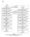
- FIG. 2is a block diagram illustrating details of one embodiment 200 of a beacon/transmitter system from which location/positioning signals as described subsequently herein may be sent.
- Transmitter embodiment 200may correspond with transmitters 110 as shown in FIG. 1 .
- transmitter embodiment 200includes various blocks for performing associated signal reception and/or processing; however, in other embodiments these blocks may be combined and/or organized differently to provide similar or equivalent signal processing, signal generation, and signal transmission. Additional block-diagram details of embodiments of circuits for generating transmitter output signals, which may be components of or integrated in transmitter 200 , in whole or in part, are described subsequently herein with respect to FIGS. 22 & 23 .
- transmitter/beacon embodiment 200may include one or more GPS modules 240 for receiving GPS signals and providing location information and/or other data, such as timing data, dilution of precision (DOP) data, or other data or information as may be provided from a GPS or other positioning system, to a processing module 210 .
- GPS modules 240for receiving GPS signals and providing location information and/or other data, such as timing data, dilution of precision (DOP) data, or other data or information as may be provided from a GPS or other positioning system, to a processing module 210 .
- DOPdilution of precision
- transmitter 200is shown in FIG. 2 with a GPS module, other modules for receiving satellite or terrestrial signals and providing similar or equivalent output signals, data, or other information may alternately be used in various embodiments.
- GPS or other timing signalsmay be used for precision timing operations within transmitters and/or for timing correction across the WAPS network.
- Transmitter 200may also include one or more transmitter modules 250 for generating and sending transmitter output signals as described subsequently herein.
- Transmitter module 250may also include various elements as are known or developed in the art for providing output signals to a transmit antenna, such as analog or digital logic and power circuitry, signal processing circuitry, tuning circuitry, buffer and power amplifiers, and the like.
- Signal processing for generating the output signalsmay be done in the processing module 210 which, in some embodiments, may be integrated with the transmitter module 250 or, in other embodiments, may be a standalone processing module for performing multiple signal processing and/or other operational functions.
- One or more memories 220may be coupled with processing module 210 to provide storage and retrieval of data and/or to provide storage and retrieval of instructions for execution in the processing module 210 .
- the instructionsmay be instructions for performing the various processing methods and functions described subsequently herein, such as for determining location information or other information associated with the transmitter, such as local environmental conditions, as well as to generate transmitter output signals to be sent to the user devices 120 as shown in FIG. 1 .
- Transmitter 200may further include one or more environmental sensing modules 270 for sensing or determining conditions associated with the transmitter, such as, for example, local pressure, temperature, or other conditions.
- pressure informationmay be generated in environmental sensing module 270 and provided to processing module 210 for integration with other data in transmitter output signals as described subsequently herein.
- One or more server interface modules 260may also be included in transmitter 200 to provide an interface between the transmitter and server systems, such as system 130 as shown in FIG. 1 , and/or to a network infrastructure, such as network infrastructure 170 as shown in FIG. 1 .
- system 130may send data or information associated with the location system and/or user devices to transmitters 200 via interface module 260 .
- transmitter 200may include other modules (not shown) to provide related operational functionality.
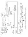
- FIG. 3is a block diagram illustrating details of one embodiment 300 of a user device or receiver 300 on which transmitter signals may be received and processed to determine location/position information.
- Receiver embodiment 300may correspond with user device 120 as shown in FIG. 1 .
- Receiver 300may include one or more GPS modules 340 for receiving GPS signals and providing location information and/or other data, such as timing data, dilution of precision (DOP) data, or other data or information as may be provided from a GPS or other positioning system, to processing module 310 . It is noted that while receiver 300 is shown in FIG. 3 with a GPS module, other modules for receiving satellite or terrestrial signals and providing similar or equivalent output signals, data, or other information may alternately be used in various embodiments.
- GPS modules 340for receiving GPS signals and providing location information and/or other data, such as timing data, dilution of precision (DOP) data, or other data or information as may be provided from a GPS or other positioning system, to processing module 310 .
- DOPdilution of precision
- Receiver 300may also include one or more cellular modules 350 for sending and receiving data or information via a cellular or other data communications system. Alternately, or in addition, receiver 300 may include communications modules (not shown) for sending and/or receiving data via other wired or wireless communications networks, such as Wi-Fi, Wi-Max, Bluetooth, USB, or other networks.
- communications modulesnot shown
- Receiver 200may include one or more position/location modules for receiving signals from terrestrial transmitters, such as transmitters 110 as shown in FIG. 1 , and processing the signals to determine position/location information as described subsequently herein.
- Module 360may be integrated with and/or may share resources such as antennas, RF circuitry, and the like with other modules, such as, for example, GPS module 340 .
- Position module 360 and GPS module 240may share some or all radio front end (RFE) components and/or processing elements.
- Processing module 310may be integrated with and/or share resources with Position module 360 and/or GPS module 340 to determine position/location information and/or perform other processing functions as described herein.
- cellular module 350may share RF and/or processing functionality with RF module 330 and/or processing module 310 .
- One or more memories 320may be coupled with processing module 310 to provide storage and retrieval of data and/or to provide storage and retrieval of instructions for execution in the processing module 310 .
- the instructionsmay be instructions for performing the various processing methods and functions described subsequently herein, such as for determining location information or other information based on received transmitter, GPS, cellular, pressure, temperature, and/or other signals or data.
- Transmitter 200may further include one or more environmental sensing modules 370 for sensing or determining conditions associated with the receiver, such as, for example, local pressure, temperature, or other conditions.
- pressure informationmay be generated in environmental sensing module 370 and provided to processing module 310 for use in determining location/position information in conjunction with received transmitter, GPS, cellular, or other signals.
- Receiver 200may further include various additional user interface modules, such as a user input module 380 , which may be in the form of a keypad, touchscreen display, mouse, or other user interface element. Audio and/or video data or information may be provided on an output module 390 , such as in the form or one or more speakers or other audio transducers, one or more visual displays, such as touchscreens, and/or other user I/O elements as are known or developed in the art.
- output module 390may be used to visually display determined location/position information based on received transmitter signals, and the determined location/position information may also be sent to cellular module 350 to an associated carrier or other entity.
- beacons/transmitterssuch as transmitters 110 as shown in FIG. 1
- FIG. 4illustrates details of an exemplary embodiment of transmitter output signaling 400 for use in providing location/position determination.
- Such signalsmay be received and processed at user devices, such as user device 120 to accurately and quickly determine location/position information (embodiments of processing methods for such signals are described subsequently herein).
- transmitter output signaling 400may be structured in the form of frames and blocks, wherein each frame may include a plurality of blocks, which may be of different types to facilitate position/location applications.
- signaling providing range and hybrid datae.g., data signaling and optionally ranging signaling or other information or signaling (also denoted here in as hybrid blocks)
- hybrid blocksmay be used to implement signaling denoted herein as “DataBurst: signaling.
- a hybrid blockincludes positioning data and ranging data. Slots in which range blocks are sent may be denoted as range slots, and slots in which hybrid blocks are sent may be denoted as data slots or hybrid slots.
- a plurality of blocksmay be sent from ones of a plurality of transmitters, with each transmitter being allocated a particular timing window (denoted herein as a “slot”) for its corresponding blocks.
- each transmittermay be allocated a single slot for transmission of one block within a frame.
- multiple slotsmay be allocated per transmitter in each frame, such as a primary slot and a secondary slot (e.g., as shown in FIG. 7A ), in which case the same or different types of blocks may be sent in a single frame.
- Various other slot allocationsmay be used in different embodiments, such as allocating slots only in every second, third, fourth, etc., frame, dynamically allocating slots based on network performance metrics, and the like.
- Example signaling 400illustrates block transmission for a single transmitter, which may be, for example, one of the transmitters 110 as shown in FIG. 1 .
- a sequence of blocksmay be sent in successive frames in a predefined slot (it is noted that, as illustrated in FIG. 8A , that multiple blocks may, in some embodiments, be sent in two or more slots in a single frame).
- the transmittermay send a first block 410 , which may be a range block, in Frame 1 , in a predefined slot, and may then may send a second block, which may be a hybrid block 420 , in the same slot in the next frame (Frame 2 ), and may then send a third block, which may be another hybrid block 430 , in the next frame (Frame 3 ).
- This particular signaling structuremay be denoted as RH 1 H 2 to indicate a sequence of Range, Hybrid 1 , and Hybrid 2 blocks transmitted in sequence.
- the patternmay then be repeated at Frames 4 , 5 , and 6 as shown.
- one or more framesmay be omitted when transmitting a sequence of range and hybrid blocks.
- fewer hybrid blockse.g., RH 1
- more hybrid blockse.g., RH 1 H 2 H 3 . . . H n
- hybrid blocksmay be included in the signaling structure.
- the DataBurst signaling structure 400uses a separate slot for each of ranging and data transmission, however, the slots are typically the same slot number in different frames or, in some cases, in two or more different slots in the same frame. In an exemplary embodiment, the slots may be separated by a period of approximately one second (e.g., a frame duration of one second), but other timing may be used in alternate embodiments.
- a range block 410 in one slot of the DataBurst structureuses BPSK pilot symbols for ranging (using, for example, seven Gold codes for preamble, 92 Gold codes for pilot symbols).
- hybrid blocks 420 and 430using, for example, four Gold codes for preamble, 16 Gold codes for pilot symbols, and 79 Gold codes for data transmission using BPSK at 1 GC/symbol).
- all blocksmay include the same first four preamble symbols, as shown in further details in FIGS. 9-11 .
- Error-correcting codesmay be used to ensure operation at low signal-to-noise ratios (SNRs), CRCs may be used to ensure that the decoded bits are valid (e.g., one error-correcting code that may be used is a convolutional code with constraint length 7 , and 16-bit CRC).
- the DataBurst signalingmay further use temporally-distributed resolution, as described in further detail subsequently herein, to reduce the number of bits, in order to fit them in as few slots as possible, while still enabling long term high accuracy.
- Use of the DataBurst structure, along with error correcting codes,enables location/positioning systems to support 102 information bits in one data packet for transmission of information used in trilateration (e.g., latitude, longitude, altitude, etc.).
- a dedicated pilot slot with a range blockmay be used for ranging (e.g., a range block such as block 410 of FIG. 4 ), which allows a relatively long coherent integration length (e.g., up to 96 ms), leading to improved ranging performance.
- the hybrid blockscan also be used for ranging in corresponding data slots, such that receivers with a high SNR can do ranging even in the data slots (for example, one Gold code integration length may be used, or use the decision on the bits to help coherently combine the signal across bits).
- a short pilot burstcan also be provided in the hybrid block in a data slot to facilitate better SNR ranging.
- Receivers with lower SNRmay perform ranging only on range blocks in the ranging slots.
- An exemplary embodimentmay transmit 93 known Gold code symbols in a range block in a ranging slot, wherein the Gold code symbols are used as pilot symbols to aid in ranging.
- 96 data GC symbolsmay be transmitted in a hybrid block in a data slot for use in transmitting information required for trilateration (e.g., transmit latitude/longitude/altitude).
- Various embodimentsmay use error-correcting codes to ensure operation at low SNRs and use CRCs to ensure that the decoded bits are valid.
- a convolutional codemay be used as the error correction code; however, other error correction codes may be used in alternate embodiments.
- the convolution codemay have a constraint-length 7 and may be a rate-1/2 code that is punctured depending on the number of info bits to ensure that the encoded bits fit within the 96 available GC symbols.
- 16 all-zero tail bitsmay be added to the information bits before encoding, due to the nature of convolutional coding and decoding.
- a CRC checkmay be accomplished by using, for example, a length-N crc CRC code. The value of N crc in an exemplary embodiment is 16.
- generation of a signalcomprises taking N info info bits, adding the 16 CRC bits, adding 16 tail bits, and encoding the resulting sequence using the convolutional code.
- the datais then punctured to ensure that it all fits within the number of bits per slot corresponding to 96 data symbols.
- the datais interleaved and transmitted over the channel to the receiver.
- the receiverdemodulates the received signal, de-interleaves the resulting soft bits and passes them through the decoder. Using the output of the decoder, the receiver does a CRC check to ensure that the block of data was sent successfully.
- An exemplary embodimentuses BPSK modulation in range blocks in ranging slots, meaning that 93 known bits are modulated onto 93 GC periods. These are the pilot bits that enable the long coherent integration times.
- the transmittermay, in some implementations, send one of N seq pilot bit sequences, in order to send a very low-information-rate signal during the ranging slot. For example, the transmitter can send one of four pilot bit sequences in order to transmit two bits of information during the ranging slot to provide some data in a ranging block.
- An exemplary embodimentmay use differential QPSK (DQPSK) modulation in data slots to facilitate data transfer at a desirable rate.
- DQPSKdifferential QPSK
- thistranslates into the ability to transmit 190 raw bits in each data slot (the first two bits are “lost” due to the differential encoding of DQPSK).
- the number of information bits per slotis lower in this implementation than 190 due to use of error-correction coding and CRC bits, as described further below.
- the WAPS of an exemplary embodimentuses BPSK modulation to transmit 16 pilot bits over 16 Gold code periods, and then uses differential BPSK (DBPSK) modulation to transmit 79 data bits over 79 Gold code periods.
- the transmittermay use the last pilot bit as the first DBPSK data bit so that it can transmit 79 data bits over 79 Gold code periods, even though it is using DBPSK.
- the same datamay be transmitted twice in two consecutive data slots. This transmission scheme allows high SNR users to use one data slot to decode the data in order to get a fast time to first fix (TTFF). This transmission scheme further allows low SNR users to soft combine the data across two data slots in order to get a reliable decoding of the data.
- TTFFfast time to first fix
- separation of the ranging and data slotsmay be used to de-link the performance of the ranging and data slots.
- Coherent integrationmay be used at a receiver across the ranging slots without the need to demodulate the data using complicated data wipe-off techniques, whereas the high symbol rate along with the modulation alphabet size allows higher rate of data transmission in the data slots.
- FIG. 5illustrates details of an example frame structure embodiment 500 .
- a frame 510may be divided into multiple slots. This is illustrated as Slots 1 to Slots N of frame 1 as 510 - 1 through 510 -N.
- Corresponding slots of subsequent frame 2are denoted as 520 - 1 through 520 -N, and a first slot of frame 3 , slot 530 - 1 , is also shown.
- each framemay be one second in length and may be divided into ten slots, resulting in a time duration of 100 milliseconds per slot. Other frame lengths and numbers of slots may be used in alternate embodiments.
- FIG. 6illustrates an example of data organization 600 in slots, such as shown in FIG. 5 , in a transmitter output signal under one embodiment, along with an example slot signaling structure.
- Signaling in slotssuch as example Frame 1 , Slot 2 , 601 - 2 , may include a pseudonoise (PN) ranging code 620 , which may be, for example, binary or quaternary, along with data 630 , which may be position/location data such as is described subsequently herein, and/or other system data.
- the PN ranging codemay be a repetition of multiple frames of a pseudorandom sequence.
- the location datamay comprise one or more symbols of data. In one embodiment, the data may be in 16 phase-shift keying (PSK) format.
- PSKphase-shift keying
- the ranging signal in terrestrial WAPS systemsis generally assumed to have a high SNR. For example if an SNR per chip of a 1023 length pseudorandom ranging signal is assumed to be 0 dB, then the SNR per PN frame would be approximately 30 dB. However, 20 dB SNR per symbol is in most cases adequate for transmission of high level information. Thus, if the majority of the transmission slot is a ranging code, in order to maximize ranging signal SNR and hence precision, then 10% of the slot can be allocated to location information transmission and while continuing to provide high throughput, for example 4 bits per slot.
- the measurement of the correlation peak amplitude and phase structuremay be used in a receiver, such as user device 120 as shown in FIG. 1 , as a channel estimation reference to help improve the demodulation of the higher order modulated location data. This may be especially important if coherent demodulation of the location data is employed in the receiver. These measurements may be used to compensate amplitude and phase fluctuations from one data symbol to the next.
- FIG. 7is a block diagram of the WAPS DataBurst signal structure 700 , under an embodiment.
- the WAPS signal structure 700comprises ten 100 ms slots in each second, denoted as Slot 1 through Slot 10 for each Frame. It is noted that only a subset of the ten slots are shown in the example signal structure 700 for clarity, but it is noted that embodiments are not so limited.
- Each WAPS transmittersuch as transmitters 110 of FIG. 1 , may be assigned one of the ten slots as their primary slot, as is further described subsequently with respect to FIG. 7 .
- the WAPS signalmay be generated from a Gold code (GC) PRN sequence and BPSK spreading in an exemplary embodiment; however, other PRN sequences and/or spreading modulation may also be used in various embodiments.
- the chipping rate of the WAPS signal in an exemplary embodimentis 1.023 megachips/second (Mcps), however, other chipping rates may be used in various embodiments.
- Each Gold codehas 1023 chips and lasts 1 ms in an exemplary embodiment such that each 100 ms slot can include 100 Gold code symbols, where one Gold code may be used as a guard time (also denoted herein as a “guard” for brevity) between slots and 99 Gold codes are available for ranging and data transmission in each 100 ms slot.
- guard timealso denoted herein as a “guard” for brevity
- Other slot configurations and allocations between symbols between ranging and data transmissionmay be used in various embodiments, and location systems may use different types of blocks, having different block types as described subsequently herein, with different allocations of symbols between data and ranging.
- each WAPS transmittermay transmits a preamble for up to seven Gold code durations, using PRN 7 .
- Ranging blocks(sent in slots denoted as ranging slots) of an exemplary embodiment comprise a preamble with a length of seven (7) Gold codes, and 92 Gold codes remain for pilot symbols.
- Hybrid blocks(sent in slots denoted as hybrid slots) may have a preamble with a length of four (4) Gold codes, and 92 Gold codes remain for pilot and data symbols.
- the first four symbols of the preamblemay be the same in all slots; however, other embodiments may use different symbols and/or different numbers of the same symbols in the preamble.
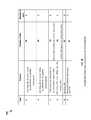
- An example list of PRNs used in one embodimentis as follows: 1, 12, 31, 32, 120, 122, 127, 131, 136, and 138.
- the WAPS of an embodimentincludes the use of DataBursts.
- the WAPS DataBurst formatgenerally divides the time available to a transmitter into ranging portions and data portions.
- transmittersmay transmit pilot symbols that enable long coherent integration.
- transmittersmay transmit data symbols at a physical-layer rate of 1 bit per Gold code period.
- FIG. 8Aillustrates details of example transmitter output signaling in a system such as system 100 of FIG. 1 using ranging and hybrid pilot blocks in correspondingly assigned slots.
- each frameis divided into 10 slots, numbered slots 1 through 10 .
- Output signals from multiple transmittersare illustrated in this example, where transmitter 1 is allocated slot 3 , transmitter 2 is allocated slot 1 , transmitter n is allocated slot 5 , and intermediate transmitters would be allocated other slots and/or may overlap with the allocated slots depending on the network configuration, number of transmitters, etc.
- the particular slot allocation shownis provided for purposes of illustration and is not intended to be limiting as to the number of slots per frame, slot allocations, or other signaling parameters.
- transmitter 1may send a range block 710 A in slot 3
- transmitter 2may send a range block 720 A in slot 1
- transmitter nmay send a range block 730 A in slot 4
- intermediately numbered transmittersmay send a range block in their correspondingly allocated slots.
- transmittersmay also be allocated additional slots in some embodiments—for example, transmitter 1 may be allocated a second slot (e.g., slot 7 ) in which to send additional blocks 713 A, 715 A.
- Other transmitterssuch as transmitters 2 through N as shown, may also be allocated additional slots in some embodiments (not shown in FIG. 7A ).
- each of the transmitters 1 , 2 , and Nmay then send a second block 712 A, 722 A, and 732 A, respectively, which may be a first hybrid block as shown in FIG. 5 , in its predefined slot.
- the processmay then repeat for successive frames.
- each transmittermay send a second hybrid block in the next frame if RH 1 H 2 signaling is used.
- each transmittersends the same type of block (e.g., a range or hybrid block) within a particular frame. This may be done through transmitter coordination and synchronization, such as between transmitters 110 through server system 130 as shown in FIG. 1 or via direct intercommunication between transmitters 110 , such as via network infrastructure 170 .
- the type of block sent by each transmitter during a particular framemay be different, either through transmitter and/or server system coordination or through each transmitter independently selecting the particular block type to transmit in each frame.
- One example of such a staggered transmitter block type signaling structureis illustrated in signaling 700 B of FIG. 7B .
- transmitter 1sends a range block 710 B in frame 1
- transmitter 2sends a hybrid block 720 B, which may be a first hybrid block of an RH 1 H 2 signal
- transmitter nsends a hybrid block 730 B.
- transmitter 1may then send a hybrid block 712 B, which may be a first hybrid block if RH 1 H 2 signaling is used, transmitter 2 may send a second hybrid block 722 B, and transmitter n may send a range block 720 B, as shown.
- a hybrid block 712 Bwhich may be a first hybrid block if RH 1 H 2 signaling is used
- transmitter 2may send a second hybrid block 722 B
- transmitter nmay send a range block 720 B, as shown.
- FIGS. 9-11illustrate details of example embodiments of block signaling formats.
- FIG. 9illustrates details of an embodiment of a range block 900 .
- Range block 900includes a range preamble signal component 910 , a range pilot signal component 920 , and an option guard signal component 920 .
- Guard signal component 920may be a particular code or symbol or symbols or may be an off or blank signal (e.g., where nothing is transmitted).
- FIG. 10illustrates details of an embodiment of a hybrid block 1000 .
- Hybrid block 1000may include a hybrid pilot signal component 1010 , which is typically shorter than the range preamble signal component 910 of FIG. 9 .
- Hybrid block 1000may further include a hybrid pilot and data signal component 1020 , as well as an optional guard signal component 1030 , which may be an off or blank signal.
- FIG. 11illustrates details of an example range preamble signal 1100 , which may correspond with range preamble 910 of FIG. 9 .
- range preamble 1100may include a hybrid preamble component 1110 , which may be the same as hybrid preamble 1010 , as well as an additional preamble signal component 1120 as shown.
- a range preamblesuch as range preamble 910 may be completely different from hybrid preamble 1010 .
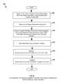
- FIG. 12illustrates details of an embodiment of a process 1200 for generating and sending transmitter output signals in a position/location system, such as system 100 as shown in FIG. 1 .
- Process 1200may be implemented in a transmitter such as transmitters 100 as shown in FIG. 1 .
- a range block including a ranging signal componentmay be generated in or received at a transmitter, such as one of transmitters 110 as shown in FIG. 12 .
- the range blockmay be sent from the transmitter to one or more receivers, such as user devices 120 as shown in FIG. 1 .
- the range blockmay be sent in a first predefined slot of a plurality of predefined slots comprising a first frame.
- a hybrid blockwhich may include a ranging signal and a positioning signal including positioning data and/or other data or information, may be generated.
- the hybrid blockmay be sent from the transmitter to one or more receivers.
- the hybrid blockmay be sent in the first predefined slot in a transmit frame that may be disjoint from the first frame.
- the disjoint framemay be one or more subsequent frames or one or more previous frames.
- the disjoint frameis the frame subsequent to the first frame; however, in other embodiments the disjoint frame may be offset by two or more frames from the first frame.
- Process 1200may further include, for example, generating, at the transmitter, a second hybrid block at stage 1225 , and sending, from the transmitter, the second hybrid block at stage 1230 .
- the second hybrid blockmay be sent in the first predefined slot in a third transmit frame.
- the third transmit framemay be disjoint from the first and/or the second transmit frames.
- One or more additional blocksmay subsequently be generated and sent at stage 1235 , such as one or more additional hybrid blocks.
- a decision stage 1240may be implemented to determine if the transmission process is to be repeated. Typically the process 1200 will be repeatedly indefinitely, in which case process execution may return to stage 1205 and repeat.
- the ranging signal sent from the transmittermay include, for example, a first random pseudo-noise (PRN) sequence.
- PRNrandom pseudo-noise
- the ranging signal sent from the transmittermay be sent with no frequency offset in the transmitter signal or at a first frequency offset in the transmitted signal.
- the range block sent from the transmittermay include, for example, a range preamble signal and a range pilot signal.
- the range block sent from the transmittermay include a guard signal or guard band.
- the guard signalmay comprise a gold code sequence.
- the guard signalmay be a blank or off signal for at least a portion of a guard time period between slots.
- the hybrid block sent from the transmittermay include, for example, a hybrid preamble signal.
- the range preamblemay include the hybrid preamble signal and an additional preamble signal.
- the hybrid block sent from the transmittermay include a hybrid preamble signal and a first set of data.
- the hybrid block sent from the transmittermay further include a hybrid pilot signal.
- the range preamble signalmay be sent with no transmit frequency offset or a first transmit frequency offset.
- the range pilot signalmay be sent with no transmit frequency offset or a second transmit frequency offset.
- the second transmit frequency offsetmay be the same as or may be different than the first transmit frequency offset.
- the hybrid preamble signalmay be sent with no frequency offset or a first transmit frequency offset.
- the first set of datamay be sent with no frequency offset or a second transmit frequency offset.
- the second transmit frequency offsetmay be the same as or may be different than the first transmit frequency offset.
- the hybrid block sent from the transmittermay, for example, include data associated with a location of the transmitter.
- the data associated with a location of the transmittermay include positional data, such as latitude and/or longitude data or other positional coordinate data or information, in one, two, or three dimensions.
- the data associated with the location of the transmitterincludes altitude information or data usable to determine altitude information, such as pressure and/or temperature data in the proximity of the transmitter, GPS data, or other altitude-related data or information.
- the data associated with the location of the transmittermay include transmitter identification information.
- the transmitter identification informationmay be information such as a transmitter identification number or numbers, system information or data assigned to or allocated to the transmitter, network information, user device information, security, encryption, or other information related to characteristics of signals being sent or received by the transmitter, or other related transmitter information.
- the data associated with the location of the transmitterincludes altitude information or data usable to determine altitude information, such as pressure and/or temperature data in the proximity of the transmitter, GPS data, or other altitude-related data or information.
- the hybrid block sent from the transmittermay include, for example, data associated with an environmental condition in the proximity of the transmitter.
- the data associated with an environmental conditionmay include pressure, temperature information, humidity information and/or other environmental information.
- the hybrid block sent from the transmittermay include, for example, data associated with a reference time and/or a reference time correction associated with the first transmitter.
- the reference time correctionmay include data defining a time offset of the transmitter data from a reference time or times.
- the hybrid block sent from the transmittermay include data associated with a transmit quality metric associated with the transmitter.
- the transmit quality metricmay be signal quality metric or other data or information associated with data traffic or wireless communication channel characteristics in the vicinity of the transmitter.
- the hybrid block sent from the transmittermay include, for example, data associated with a packet type of the hybrid block.
- the hybrid block sent from the transmittermay include encrypted data.
- the hybrid block sent from the transmittermay include data with error control coding.
- the error control codingmay comprise convolutional encoding.
- the hybrid block sent from the transmittermay include cyclical redundant checking (CRC) data.
- the transmit framesmay have a duration of one second or approximately one second.
- the plurality of predefined slots per framemay consist of ten slots. In other embodiments the transmit frame may have a duration greater or less than one second, and more than or fewer than 10 slots may within each frame.
- the first transmit framemay be sent using binary phase shift keying (BPSK) or quadrature phase shift keying (QPSK). In other embodiments different modulation methods, such as OQPSK, MSK, OFDM, ASK, QAM, and/or other modulation schemes may be used.
- BPSKbinary phase shift keying
- QPSKquadrature phase shift keying
- different modulation methodssuch as OQPSK, MSK, OFDM, ASK, QAM, and/or other modulation schemes may be used.
- the hybrid block sent from the transmittermay include a plurality of data symbols.
- the plurality of data symbolsmay consist of ninety nine data symbols.
- the hybrid blockmay further include a guard signal.
- the guard signalmay be a blank or off signal.
- the hybrid blockmay include a preamble. In an exemplary embodiment the preamble may consist of seven symbols.
- FIG. 13illustrates details of an embodiment of a process 1300 for transmission of positioning/location signals from multiple transmitters (in this example only two are illustrated for clarity, however, in a typical implementation three or more transmitters will be used to facilitate trilateration), such as two of the transmitters 110 as shown in FIG. 1 .
- two transmittersdenoted as transmitter 1 and transmitter 2 , send transmitter output signals simultaneously.
- the signalingis typically synchronized to at least the level of slot timing so that each transmitter is synchronized to send signals only it its designated slot, as described previously herein.
- the transmittersmay be time synchronized for slot timing by receiving time reference data from systems such as a GPS system, such as GPS satellites 150 as shown in FIG.
- the transmittersmay be synchronized to send the same type of block in each frame, such as, for example, by synchronizing all transmitters to send a range block in frame 1 , a first hybrid block in frame 2 , a second hybrid block in frame 3 , etc. This may be done through a block type synchronization stage 1352 as shown, wherein the transmitters synchronize to send the same type of block in a given frame.
- the transmittersmay not be block synchronized but may just transmit the next successive block in their respective signaling sequence during their allocated predefined slot.
- the transmittersare block synchronized and therefore generate the same type of blocks for transmission in a particular frame; however, in other embodiments the block generation sequences would be offset accordingly based on the particular block sequence of each transmitter.
- each of transmitters 1 and 2may perform the same or similar processing stages to those described in FIG. 12 , which may or may not be synchronized to the block type level.
- ranging blockswhich may include a ranging signal component may be generated in or received at each transmitter, such as two of the transmitters 110 as shown in FIG. 12 .
- the range blockmay be sent from the transmitters to one or more receivers, such as user devices 120 as shown in FIG. 1 .
- the range block for the first transmittermay be sent in a first predefined slot of a plurality of predefined slots comprising a first frame, while the range block for the second transmitter may be sent in a second predefined slot of the plurality of predefined slots in the same frame.
- hybrid blockswhich may include ranging signals and positioning signals including positioning data and/or other data or information, may be generated.
- the hybrid blocksmay be sent from the transmitters to one or more receivers in their respective predefined slots.
- the hybrid blockmay be sent from the first transmitter in the first predefined slot in a transmit frame that may be disjoint from the first frame, while the hybrid block from the second transmitter may be sent in the second predefined slot, also in a disjoint transmit frame.
- the disjoint transmit framesmay be one or more subsequent frames or one or more previous frames.
- the disjoint frameis the frame subsequent to the first frame; however, in other embodiments the disjoint frame may be offset by two or more frames from the first frame.
- Process 1300may further include, for example, generating, at the transmitters, a second pair of hybrid blocks at stages 1325 , 1375 , respectively, and sending, from the transmitters, the second hybrid blocks at stage 1330 , 1380 , respectively.
- the second hybrid blocksmay be sent in the first and second predefined slots in a third transmit frame.
- the third transmit framemay be disjoint from the first and/or the second transmit frames.
- One or more additional blocksmay subsequently be generated and sent from the two transmitters at stage 1335 , 1385 , respectively, such as one or more additional hybrid blocks or other block types.
- a decision stage 1240may be implemented to determine if the transmission process is to be repeated. Typically the process 1200 will be repeatedly indefinitely, in which case process execution may return to stage 1205 and repeat.
- the ranging signal sent from the transmittermay include, for example, a first random pseudo-noise (PRN) sequence.
- the ranging signal sent from the second transmittermay include a second PRN sequence.
- the first PRN sequencemay be the same as or different from the second PRN sequence.
- the ranging signal sent from the transmittermay be sent with no frequency offset in the transmitter signal or at a first frequency offset in the transmitted signal.
- the ranging signal sent from the second transmittermay be sent at no frequency offset or at a second frequency offset.
- the first frequency offsetmay be the same as or different than the second frequency offset.
- the range blockmay be sent from the second transmitter in the first frame or in a frame disjoint from the first frame.
- the range blocks sent from the transmittersmay include, for example, a range preamble signal and a range pilot signal.
- the range blocks sent from the transmittersmay include a guard signal or guard band.
- the guard signalmay comprise a gold code sequence.
- the guard signalmay be a blank or off signal for at least a portion of a guard time period between slots.
- the hybrid blocks sent from the transmittersmay include, for example, a hybrid preamble signal.
- the range preamblemay include the hybrid preamble signal and an additional preamble signal.
- the hybrid blocks sent from the transmittersmay include a hybrid preamble signal and a first set of data.
- the hybrid blocks sent from the transmittersmay further include a hybrid pilot signal.
- the range preamble signalmay be sent with no transmit frequency offset or a first transmit frequency offset.
- the range pilot signalmay be sent with no transmit frequency offset or a second transmit frequency offset.
- the second transmit frequency offsetmay be the same as or may be different than the first transmit frequency offset.
- the hybrid preamble signalmay be sent with no frequency offset or a first transmit frequency offset.
- the first set of datamay be sent with no frequency offset or a second transmit frequency offset.
- the second transmit frequency offsetmay be the same as or may be different than the first transmit frequency offset.
- the hybrid blocks sent from the transmittersmay, for example, include data associated with a location of the respective transmitters.
- the data associated with a location of the transmittersmay include positional data, such as latitude and/or longitude data or other positional coordinate data or information, in one, two, or three dimensions.
- the data associated with the location of the transmittersmay include altitude information or data usable to determine altitude information, such as pressure and/or temperature data in the proximity of the transmitter, GPS data, or other altitude-related data or information.
- the data associated with the location of the transmittersmay include transmitter identification information for the respective transmitters.
- the transmitter identification informationmay be information such as a transmitter identification number or numbers, system information or data assigned to or allocated to the transmitter, network information, user device information, security, encryption, or other information related to characteristics of signals being sent or received by the transmitter, or other related transmitter information.
- the data associated with the location of the transmittersmay include altitude information or data usable to determine altitude information, such as pressure and/or temperature data in the proximity of the transmitter, GPS data, or other altitude-related data or information.
- the hybrid blocks sent from the transmittersmay include, for example, data associated with an environmental condition in the proximity of the respective transmitters.
- the data associated with an environmental conditionmay include pressure, temperature information, humidity information and/or other environmental information.
- the hybrid block sent from the transmittersmay include, for example, data associated with a reference time and/or a reference time correction associated with the transmitters.
- the reference time correctionmay include data defining a time offset of the transmitter data from a reference time or times.
- the hybrid blocks sent from the transmittersmay include data associated with a transmit quality metric associated with the transmitter.
- the transmit quality metricmay be signal quality metric or other data or information associated with data traffic or wireless communication channel characteristics in the vicinity of the transmitter.
- the hybrid blocks sent from the transmittersmay include, for example, data associated with a packet type of the hybrid block.
- the hybrid blocks sent from the transmittersmay include encrypted data.
- the hybrid blocks sent from the transmittersmay include data with error control coding.
- the error control codingmay comprise convolutional encoding.
- the hybrid blocks sent from the transmittersmay include cyclical redundant checking (CRC) data.
- the range blocks sent from the transmittersmay include, for example, a preamble and a first transmitter sequence encoded with a first spreading code.
- the range block sent from the second transmittermay include the preamble and a second transmitter sequence.
- the second transmitter sequencemay be encoded with a second spreading code.
- the second spreading codemay be the same as or different than the first spreading code.
- the first and second spreading codesmay be Gold codes.
- the Gold codesmay be different codes.
- the first and second spreading codesmay be other spreading codes.
- the transmit framesmay have a duration of one second or approximately one second.
- the plurality of predefined slots per framemay consist of ten slots. In other embodiments the transmit frame may have a duration greater or less than one second, and more than or fewer than 10 slots may within each frame.
- the first transmit framemay be sent using binary phase shift keying (BPSK) or quadrature phase shift keying (QPSK). In other embodiments different modulation methods, such as OQPSK, MSK, OFDM, ASK, QAM, and/or other modulation schemes may be used.
- BPSKbinary phase shift keying
- QPSKquadrature phase shift keying
- different modulation methodssuch as OQPSK, MSK, OFDM, ASK, QAM, and/or other modulation schemes may be used.
- the hybrid blocks sent from the transmittersmay include a plurality of data symbols.
- the plurality of data symbolsmay consist of ninety nine data symbols.
- the hybrid blocksmay further include a guard signal.
- the guard signalmay be a blank or off signal.
- the hybrid blocksmay include a preamble. In an exemplary embodiment the preamble may consist of seven symbols.
- the hybrid block sent from the transmittermay include, for example, a first portion of data associated with a transmitter parameter, and the second hybrid block may include a second portion of data associated with the transmitter parameter.
- the first portion of datamay represent a first lowered resolution value of the transmitter parameter
- the second portion of datarepresents a second lowered resolution value of the transmitter parameter.
- the first lowered resolution value and the second lowered resolution valuemay be the same lowered resolution values or may be different lowered resolution values.
- the first lowered resolution value and the second lowered resolution valuemay be selected so as to be usable in combination to generate a higher resolution value at a receiver.
- the transmitter parametermay be a position value.
- the position valuemay be a longitude value.
- the position valuemay be a latitude value.
- the position valuemay be an alternate location coordinate value.
- the position valuemay be an altitude value.
- the transmitter parametermay be an environmental parameter value in proximity to the transmitter.
- the environmental parametermay be a temperature value.
- the environmental valuemay be
- datamay be sent from a transmitter to a receiver/user device using a format described herein as temporally distributed resolution (also denoted as TDR).
- TDRtemporally distributed resolution
- datais sent from a transmitter, such as transmitters 110 of FIG. 1 , in blocks of lowered resolution data, which may then be combined at a receiver, such as user device 120 of FIG. 1 , to generate higher resolution data.
- FIG. 14illustrates an example embodiment of a process 1400 for generating DataBurst TDR transmitter output signals at a transmitter.
- the transmittermay send a range block, such as described previously herein, as part of a DataBurst transmit sequence.
- the transmittermay measure or determine data to be sent, such as positional data or other data, and/or may retrieve the data from a stored memory, such as memory 220 of FIG. 2 , and may then divide the data into two or more portions. Each of the portions may be at a lowered resolution with respect to the source data.
- a first portion of the datamay be sent from the transmitter, such as in a hybrid block as described previously herein.
- the hybrid blockmay be a first hybrid block of a sequence of blocks, such as an RH 1 H 2 sequence as described previously.
- Subsequent transmission of additional portions of the lowered resolution datamay be sent sequentially, such as in the second hybrid block of a RH 1 H 2 sequence; however, the subsequent portions need not be so constrained and may be sent in later frames, etc.
- an optional range block or blocksmay be sent at stage 1415 , and/or other hybrid blocks containing other data may also be sent before the remaining portions of the lowered resolution data are transmitter.
- an additional portion of the lowered resolution datamay be sent, such as in another hybrid block.
- other range and/or hybrid blocksmay be subsequently sent.
- a decisionmay be performed at stage 1430 to determine whether additional portions need to be sent. If so, the processing may return to stage 1425 to send one or more additional portions. Alternately, processing may end if no further portions need to be sent. In some implementations, no decision stage is used, such as when a fixed number of portions are defined for transmission in a corresponding number of hybrid blocks.
- the number of bits used to transmit information necessary for trilaterationis approximately 109.
- Example trilateration informationincludes data defining transmitter latitude, longitude, altitude, temperature, pressure, transmitter correction, transmitter quality, and framing overhead. This is illustrated in Table 1500 A of FIG. 15A .
- One TDR embodimentreduces the number of information bits required per slot from approximately 109 to approximately 102, and send multiple transmissions of the 109 bit data, reduced to 102 bits, where it may then be restored at the receiver/user device.
- the motivation for reducing the number of information bits per slotis so the transmitter can reduce the number of bits to match what the channel can support, while still enabling full resolution over time.
- FIG. 15Billustrates a table 1500 B that includes trilateration information or parameters for another embodiment.
- This alternative embodimentreduces the number of information bits required per slot from approximately 109 to approximately 94. While reducing the number of bits required and, consequently re-doing the resolution, this alternative still provides meter-level resolution in the various trilateration parameters.
- each data slote.g., each hybrid block
- enough datais sent to do a fix with meter-level accuracy in the various parameters, which leads to a fast TTFF.
- TTFFtime to frame
- FIG. 16illustrates a table 1600 that includes the transmit information for each of multiple transmit periods (e.g, transmission of multiple hybrid blocks, such as shown in FIG. 14 ), under an embodiment.
- Transmit periods 1 - 3 , 5 - 7 , 9 , and 10each transmit the value “523,” while transmits periods 4 and 8 transmit the value “524.”
- FIG. 17illustrates a table 1700 that includes results of the receiver calculations for the transmit information of the example, under an embodiment.
- the receiver resultsshow that after four (4) transmit periods, the error drops to approximately 1 cm, and after nine (9) transmit periods, the error drops to approximately zero, which demonstrates the achievement of centimeter-level accuracy.
- the transmit periodis two (2) seconds, then within two (2) seconds the receiver has enough information to perform a rough position highest accuracy fix (e.g., centimeter level accuracy).
- This TDR method of sending multiple lower resolution data portions as described abovecan readily be translated to binary representations of numbers as well. For example, using a value having a length of 20 bits, with 4 bits accuracy (i.e. the value is in 1/16 th of a meter or other unit), then one of the following transmit schemes can be used: transmit 19 bits, with 3 bits accuracy each time and 4 bits accuracy after 2 transmissions; transmit 18 bits, with 2 bits accuracy each time and 4 bits accuracy after 4 transmissions; transmit 17 bits, with 1 bits accuracy each time and 4 bits accuracy after 8 transmissions.
- the number of bits transmitted each timecan be reduced by 3 bits (17 bits instead of 20 bits) and, assuming a transmit period of two (2) seconds, the accuracy realized is as follows: 1 bit accuracy after 2 seconds; 2 bit accuracy after 4 seconds; 3 bit accuracy after 8 seconds; full 4-bit accuracy after 16 seconds.
- FIG. 18illustrates details of an embodiment of a process 1800 for determining position information at a receiver, such as user device 120 of FIG. 1 , which may be configured as shown in device 300 of FIG. 3 , based on multiple received trilateration signals.
- the receivermay receive trilateration signals in a DataBurst format, such as described previously herein, from three or more transmitters.
- These transmitter signalsinclude data sufficient to determine, based on trilateration, a position of the receiver.
- Pressure datadetermined at the transmitters, such as through module 270 of FIG. 2 , and sent from the transmitters, may be used in conjunction with locally measured pressure data at the receiver, such as may be determined in module 370 of FIG. 3 at stage 1810 , to determine altitude of the receiver.
- the altitudemay be determined at the receiver based on a known altitude of the transmitter, which may be sent from the transmitter as data, along with a determined pressure differential, which, if the transmitters are in close enough proximity to the receivers, may be assumed to be under the same environmental pressure conditions, thereby allowing altitude determination based on a pressure difference between the transmitter pressure and local receiver pressure data.
- location of the user devicewhich may be done in three dimensions (e.g., latitude, longitude, and altitude, or in equivalent parameters other three-dimensional coordinate systems).
- the location informationmay be determined using pressure data as described above; however, in other embodiments location may be determined based on trilateration information alone or through use of other data, such as may be provided by server system 130 of FIG. 1 .
- the determined location informationmay be stored in a memory of the receiver, such as in memory 320 of FIG. 3 .
- the determined informationmay be sent to a carrier or other entity at stage 1825 , such as through cellular/wireless module 350 , and/or may optionally be displayed at stage 1830 , such as on display 390 .
- FIG. 19illustrates details of an embodiment of a process 1900 for processing temporally distributed data (TDR) received at a receiver/user device, such as user device 120 as shown in FIG. 1 .
- a first transmitter output signal including data representing a parameter at a first reduced resolutionmay be received at the receiver/user device.
- the received signalmay be, for example, in a first hybrid packet.
- the datamay be extracted from the incoming signal and stored in a memory, such as memory 320 as shown in FIG. 3 , at stage 1910 .
- another signalmay be received with data representing the parameter at a reduced resolution, which may be at a different reduced resolution value than the first packet.
- This packetmay be, for example, a second hybrid packet in an RH 1 H 2 DataBurst signaling sequence.
- the additional reduced resolution parametermay likewise be extracted and stored in a memory at stage 1920 .
- the reduced resolution valuesmay be continuously added to a cumulative higher resolution estimate of the parameter, or, in other embodiments, a decision stage 1925 may be included to determine whether additional lower resolution packets should be received before determining an estimate of the higher resolution parameter value. In this case, if additional lower resolution packets are needed, the process may repeat from stage 1915 until sufficient packets have been received.
- a higher resolution value of the parametermay then be determined, such as described previously with respect to FIGS. 15-17 , at stage 1930 .
- FIG. 20illustrates details of a set of example packet payload parameters and values in table 2000 , accordance with an exemplary embodiment.
- Example parametersmay include, for example, latitude, longitude, altitude, pressure, temperature, transmitter IDs, timing information, such as GPS timing, security information, encryption information, and/or other information.
- FIG. 21illustrates details of packet formats and header values in accordance with an exemplary embodiment.
- two packet typesshown as packet types 0 or 1 ( 2110 ) and all other packet types ( 2120 ) may be used.
- Bits of a packet headermay be formatted as shown, e.g., including a packet type, encryption bit(s), start and stop bits, and/or other header data or information (not shown).
- Sequence 2130illustrates one example of packets transmitted in accordance with this packet formatting. In particular, example start and stop frame packets, along with intermediate payload packets, are shown. These may be, for example, sent as hybrid packets, such as hybrid 1 , hybrid 2 packets as described previously herein. Sequences 2140 and 2150 illustrate other example packets.
- FIG. 22illustrates details of an embodiment of a convolution encoder circuit 2200 that may be used to generate transmitter output signals, such as in transmitters 110 as shown in FIG. 1 .
- datamay be received, such as a 102 bit sequence for transmission as described previously herein, and may have a CRC applied at stage 2205 , resulting in a bit stream of 118 bits. This may be divided into two bit sequences at multiplexer 2210 , and tail bits may be added at block 2215 , resulting in an outgoing bit sequence of 65 bits.
- a convolutional encoder 2220which may have a rate of 1/2, may then encode the bit stream, resulting in an output sequence of 130 bits. These may be punctured and interleaved to provide 80 output bits.
- Encoder embodiment 2200is shown for purposed of illustration, not limitation, and it will be apparent that other encoding circuits and configurations may be used in various other embodiments.
- FIG. 23illustrates details of an embodiment of a circuit 2300 for encoding and modulating data for transmission as an output signal, such as at transmitters 110 as shown in FIG. 1 .
- incoming data 2305 . 2307such as, for example, position data, environmental data, message, identification information, and/or other data as described herein, may be provided to a data generator module 2310 , where it may be processed and/or combined and provided to a forward error correction (FEC)/Encryption module 2315 .
- FECforward error correction
- a multiplexer 2325may select either a pilot/preamble sequence, such as from pilot/preamble module 2320 , or the data output from module 2315 , and the output may then be applied to a data spreader 2330 (e.g., an exclusive or gate or other spreading circuit) where it may be spread by a spreading sequence, such as a sequence generated at a gold code generator module 2335 , or other spreading sequence generation module.
- a pilot/preamble sequencesuch as from pilot/preamble module 2320
- the data outputmay then be applied to a data spreader 2330 (e.g., an exclusive or gate or other spreading circuit) where it may be spread by a spreading sequence, such as a sequence generated at a gold code generator module 2335 , or other spreading sequence generation module.
- the outputmay then be applied to a transmit filter 2350 and separated into I and Q data components, rotated 90 degrees in rotator module 2355 , applied to corresponding I and Q digital-to-analog converters (DACs) 2362 , 2364 , provided to a baseband filter 2370 , an I/Q modulator 2375 , and an RF output module 2380 , where it may then be provided to an output power amplifier (PA) for transmission (not shown).
- PAoutput power amplifier
- a preamble selection multiplexer 2340may be used to select an appropriate preamble.
- QPSK modulationmay be used for data transmission in some embodiments.
- QPSK modulation of the transmit signalwhile using the same BPSK spreading and spectrum shaping filter, maintains the same peak-to-average ratio almost identically.
- back-offsuch as PA back-off
- the ranging signalmay be BPSK modulated with BPSK spreading (same as GPS), so that the GPS receiver can be re-used for acquisition and tracking of the WAPS ranging signal.
- received QPSK data modulationmay effect the receiver, such as if a GPS radio front end is used.
- the GPS signalcomprises BPSK spreading of a BPSK modulated data sequence.
- the QPSK modulated datamay be spread using a BPSK spreading sequence.
- the acquisition processing block of a GNSS receivercan be re-used to process the WAPS signal, irrespective of whether it a software GPS receiver or a hardware GPS receiver, and irrespective of whether a linear or squared detector is used in the acquisition process.
- the detection performancewill be identical for QPSK modulation when compared with BPSK modulation.
- the GNSS tracking blockscan also be re-used with minor modifications.
- the GNSS data demodulationis generally performed in firmware or software so, with minor modifications to the frequency tracking loop to account for the QPSK data modulation, the WAPS data demodulation can be performed using the same processing capability.
- Positioning signals from transmitterscomprise two portions of data, a first portion that is pulsed so as not to interfere with the transmission of other transmitters and a second portion that is on in a continuous manner which allows for improved data throughput and signal acquisition speed.
- CDMAcode division multiple access
- TDMAtime division multiple access
- FDMAfrequency division multiple access
- CDMA transmitterstypically operate concurrently and mutual interference is reduced by having different transmitters transmit distinct coded signals, which have low cross correlation properties.
- TDMAdifferent transmitters are assigned different times of transmission, sometimes called “slots” and one and only one transmitter is permitted to transmit during a slot.
- FDMAdifferent transmitters are assigned different frequency passbands.
- the positioning information transmitted by the transmittersincludes precision timing sequences, and positioning data, the latter including the location of transmitters, various timing corrections.
- the positioning datamay be provided in a number of ways. For example, it may be modulated onto a coded timing sequence, it may be added or overlaid over the timing sequence, or it may be concatenated with the timing sequence.
- the most common wide area positioning systemis the Global Position Satellite System (GPS) which for the timing sequence employs a set of distinct pseudonoise sequences chosen among a set of Gold Codes of length 1023 .
- GPSGlobal Position Satellite System
- different transmittersare assigned slots and the transmitters only broadcast positioning data in their assigned slots, hence producing minimal mutual interference with their neighbors.
- Embodiments described hereinmay use transmitters transmitting on a continuous basis. However, certain portions of the positioning data may be sent at distinct times so as not to provide mutual interference.
- the coded timing sequencesare pulsed and at least a portion of the positioning information, such as transmitter location data, is broadcast by each transmitter in a continuous basis.
- a portion of the positioning information broadcast continuously from each transmitteris simulcast, meaning the data is identical. Simulcast allows a rapid and reliable distribution of data such as transmitter identification and location. This in turn allows a receiving platform to rapidly synchronize itself to the network and determine the number of location of transmitters.
- Other data that may be included in such simulcastsinclude transmitter health data and user authorization data.
- the sync signalmay be broadcast simultaneously from all transmitters in the system enabling quick receiver synchronization to the network.
- embodiments described hereinmay have cross interference if the transmitters are continuously broadcasting positioning data.
- the continuously broadcast positioning datais received by receivers concurrently with precision timing data and other positioning data from a transmitter.
- This cross interferencemay be minimized by utilizing a narrowband format for the continuous positioning data.
- the continuous positioning data and the precision timing datamay be separated by standard filtering methods. Nevertheless, a higher RF instantaneous dynamic range is used since, in many cases, the continuously received positioning data from one transmitter may be at a much higher level than the precision timing data.
- a particular transmittersay transmitter A
- Each group of three framesmay correspond to a data bit of information. These three repetitive frames may be integrated in order to produce a precision timing measurement.
- Low speed datamay be incorporated on such a group of three frames by phase or differential phase modulation. Assume that 100 frames are transmitted by this transmitter and hence 33 bits of data, assuming biphase coding. This total period is 102.3 milliseconds in length. Concurrently, this transmitter transmits 1 symbol of data per repetition interval again by phase or differential phase modulation.
- transmitter Aceases the transmission of the precision coded sequence but continues its transmission of positioning data.
- transmitter Bbegins a similar sequence.
- transmitter Bhad been transmitting continuous positioning information during the period during which transmitter A was transmitting its precision timing data. The sequence continues in this manner.
- each transmittertransmits at most 33 symbols of data via modulation of its coded sequence during a period of 0.72 seconds.
- the continuous transmission portion of the transmission from a given transmittercorresponds to 722 symbols of data.
- the composite ratewould only be 132 symbols if transmitters only transmitted during a particular period of 102.3 msec.
- Higher throughput of the continuous transmissionmay be achieved through the use of higher order modulation, such as differential quadraphase shift keying.
- Communication pathscouple the components and include any medium for communicating or transferring files among the components.
- the communication pathsinclude wireless connections, wired connections, and hybrid wireless/wired connections.
- the communication pathsalso include couplings or connections to networks including local area networks (LANs), metropolitan area networks (MANs), wide area networks (WANs), proprietary networks, interoffice or backend networks, and the Internet.
- LANslocal area networks
- MANsmetropolitan area networks
- WANswide area networks
- proprietary networksinteroffice or backend networks
- the Internetand the Internet.
- the communication pathsinclude removable fixed mediums like floppy disks, hard disk drives, and CD-ROM disks, as well as flash RAM, Universal Serial Bus (USB) connections, RS-232 connections, telephone lines, buses, and electronic mail messages.
- USBUniversal Serial Bus
- aspects of the systems and methods described hereinmay be implemented as functionality programmed into any of a variety of circuitry, including programmable logic devices (PLDs), such as field programmable gate arrays (FPGAs), programmable array logic (PAL) devices, electrically programmable logic and memory devices and standard cell-based devices, as well as application specific integrated circuits (ASICs).
- PLDsprogrammable logic devices
- FPGAsfield programmable gate arrays
- PALprogrammable array logic
- ASICsapplication specific integrated circuits
- microcontrollers with memorysuch as electronically erasable programmable read only memory (EEPROM)
- EEPROMelectronically erasable programmable read only memory
- embedded microprocessorsfirmware, software, etc.
- aspects of the systems and methodsmay be embodied in microprocessors having software-based circuit emulation, discrete logic (sequential and combinatorial), custom devices, fuzzy (neural) logic, quantum devices, and hybrids of any of the above device types.
- the underlying device technologiesmay be provided in a variety of component types, e.g., metal-oxide semiconductor field-effect transistor (MOSFET) technologies like complementary metal-oxide semiconductor (CMOS), bipolar technologies like emitter-coupled logic (ECL), polymer technologies (e.g., silicon-conjugated polymer and metal-conjugated polymer-metal structures), mixed analog and digital, etc.
- MOSFETmetal-oxide semiconductor field-effect transistor
- CMOScomplementary metal-oxide semiconductor
- bipolar technologieslike emitter-coupled logic (ECL)
- polymer technologiese.g., silicon-conjugated polymer and metal-conjugated polymer-metal structures
- mixed analog and digitaletc.
- any system, method, and/or other components disclosed hereinmay be described using computer aided design tools and expressed (or represented), as data and/or instructions embodied in various computer-readable media, in terms of their behavioral, register transfer, logic component, transistor, layout geometries, and/or other characteristics.
- Computer-readable media in which such formatted data and/or instructions may be embodiedinclude, but are not limited to, non-volatile storage media in various forms (e.g., optical, magnetic or semiconductor storage media) and carrier waves that may be used to transfer such formatted data and/or instructions through wireless, optical, or wired signaling media or any combination thereof.
- Examples of transfers of such formatted data and/or instructions by carrier wavesinclude, but are not limited to, transfers (uploads, downloads, e-mail, etc.) over the Internet and/or other computer networks via one or more data transfer protocols (e.g., HTTP, HTTPs, FTP, SMTP, WAP, etc.).
- data transfer protocolse.g., HTTP, HTTPs, FTP, SMTP, WAP, etc.
- a processing entitye.g., one or more processors
- the words “comprise,” “comprising,” and the likeare to be construed in an inclusive sense as opposed to an exclusive or exhaustive sense; that is to say, in a sense of “including, but not limited to.” Words using the singular or plural number also include the plural or singular number respectively. Additionally, the words “herein,” “hereunder,” “above,” “below,” and words of similar import, when used in this application, refer to this application as a whole and not to any particular portions of this application. When the word “or” is used in reference to a list of two or more items, that word covers all of the following interpretations of the word: any of the items in the list, all of the items in the list and any combination of the items in the list.
- the functions, methods and processes describedmay be implemented in whole or in part in hardware, software, firmware, or any combination thereof. If implemented in software, the functions may be stored on or encoded as one or more instructions or code on a computer-readable medium.
- Computer-readable mediaincludes computer storage media. Storage media may be any available media that can be accessed by a computer.
- Such computer-readable mediacan include RAM, ROM, EEPROM, CD-ROM or other optical disk storage, magnetic disk storage or other magnetic storage devices, or any other medium that can be used to carry or store desired program code in the form of instructions or data structures and that can be accessed by a computer.
- Disk and discincludes compact disc (CD), laser disc, optical disc, digital versatile disc (DVD), floppy disk and Blu-ray disc where disks usually reproduce data magnetically, while discs reproduce data optically with lasers. Combinations of the above should also be included within the scope of computer-readable media.
- DSPdigital signal processor
- ASICapplication specific integrated circuit
- FPGAfield programmable gate array
- a general purpose processormay be a microprocessor, but in the alternative, the processor may be any conventional processor, controller, microcontroller, or state machine.
- a processormay also be implemented as a combination of computing devices, e.g., a combination of a DSP and a microprocessor, a plurality of microprocessors, one or more microprocessors in conjunction with a DSP core, or any other such configuration.
- a software modulemay reside in RAM memory, flash memory, ROM memory, EPROM memory, EEPROM memory, registers, hard disk, a removable disk, a CD-ROM, or any other form of storage medium known in the art.
- An exemplary storage mediumis coupled to the processor such that the processor can read information from, and write information to, the storage medium.
- the storage mediummay be integral to the processor.
- the processor and the storage mediummay reside in an ASIC.
- the ASICmay reside in a user terminal.
- the processor and the storage mediummay reside as discrete components in a user terminal.
Landscapes
- Engineering & Computer Science (AREA)
- Radar, Positioning & Navigation (AREA)
- Remote Sensing (AREA)
- Physics & Mathematics (AREA)
- General Physics & Mathematics (AREA)
- Computer Networks & Wireless Communication (AREA)
- Position Fixing By Use Of Radio Waves (AREA)
- Signal Processing (AREA)
- Mobile Radio Communication Systems (AREA)
Abstract
Description
value=(sum{k=1:N}tx_value[k])*10/N.
Claims (62)
Priority Applications (4)
| Application Number | Priority Date | Filing Date | Title |
|---|---|---|---|
| US13/535,128US9035829B2 (en) | 2008-09-10 | 2012-06-27 | Wide area positioning systems and methods |
| US14/668,849US9784815B2 (en) | 2011-06-28 | 2015-03-25 | Separating ranging and data signals in a wireless positioning system |
| US14/673,173US9797982B2 (en) | 2008-09-10 | 2015-03-30 | Signaling in a wireless positioning system |
| US15/706,076US10598758B2 (en) | 2011-06-28 | 2017-09-15 | Signaling in a wireless positioning system |
Applications Claiming Priority (8)
| Application Number | Priority Date | Filing Date | Title |
|---|---|---|---|
| US9585608P | 2008-09-10 | 2008-09-10 | |
| US16302009P | 2009-03-24 | 2009-03-24 | |
| US12/557,479US8130141B2 (en) | 2008-09-10 | 2009-09-10 | Wide area positioning system |
| US201161502272P | 2011-06-28 | 2011-06-28 | |
| US201161502276P | 2011-06-28 | 2011-06-28 | |
| US201161514369P | 2011-08-02 | 2011-08-02 | |
| US13/412,487US8629803B2 (en) | 2008-09-10 | 2012-03-05 | Wide area positioning system |
| US13/535,128US9035829B2 (en) | 2008-09-10 | 2012-06-27 | Wide area positioning systems and methods |
Related Parent Applications (1)
| Application Number | Title | Priority Date | Filing Date |
|---|---|---|---|
| US13/412,487Continuation-In-PartUS8629803B2 (en) | 2008-09-10 | 2012-03-05 | Wide area positioning system |
Related Child Applications (2)
| Application Number | Title | Priority Date | Filing Date |
|---|---|---|---|
| US14/668,849Continuation-In-PartUS9784815B2 (en) | 2011-06-28 | 2015-03-25 | Separating ranging and data signals in a wireless positioning system |
| US14/673,173ContinuationUS9797982B2 (en) | 2008-09-10 | 2015-03-30 | Signaling in a wireless positioning system |
Publications (2)
| Publication Number | Publication Date |
|---|---|
| US20130169484A1 US20130169484A1 (en) | 2013-07-04 |
| US9035829B2true US9035829B2 (en) | 2015-05-19 |
Family
ID=53546026
Family Applications (2)
| Application Number | Title | Priority Date | Filing Date |
|---|---|---|---|
| US13/535,128Active2030-09-11US9035829B2 (en) | 2008-09-10 | 2012-06-27 | Wide area positioning systems and methods |
| US14/673,173Active2033-06-07US9797982B2 (en) | 2008-09-10 | 2015-03-30 | Signaling in a wireless positioning system |
Family Applications After (1)
| Application Number | Title | Priority Date | Filing Date |
|---|---|---|---|
| US14/673,173Active2033-06-07US9797982B2 (en) | 2008-09-10 | 2015-03-30 | Signaling in a wireless positioning system |
Country Status (1)
| Country | Link |
|---|---|
| US (2) | US9035829B2 (en) |
Cited By (5)
| Publication number | Priority date | Publication date | Assignee | Title |
|---|---|---|---|---|
| US20180284253A1 (en)* | 2015-10-02 | 2018-10-04 | Mbda France | Method and device for determining the distance between an airborne receiver and a stationary ground transmitter |
| US10775510B2 (en) | 2016-06-06 | 2020-09-15 | Brian G. Agee | Blind despreading of civil GNSS signals for resilient PNT applications |
| US10895648B2 (en) | 2003-06-27 | 2021-01-19 | Qualcomm Incorporated | Method and apparatus for wireless network hybrid positioning |
| US12228656B2 (en) | 2016-06-06 | 2025-02-18 | Brian G. Agee | Resilient despreading of terrestrial navigation signals |
| US12386015B2 (en) | 2020-02-03 | 2025-08-12 | Brian G. Agee | Resilient distributed positioning networks |
Families Citing this family (21)
| Publication number | Priority date | Publication date | Assignee | Title |
|---|---|---|---|---|
| US9035829B2 (en) | 2008-09-10 | 2015-05-19 | Nextnav, Llc | Wide area positioning systems and methods |
| EP3086619A1 (en) | 2008-09-10 | 2016-10-26 | Nextnav, LLC | Wide area positioning system |
| US9119165B2 (en) | 2009-09-10 | 2015-08-25 | Nextnav, Llc | Coding in a wide area positioning system (WAPS) |
| US9057606B2 (en) | 2009-09-10 | 2015-06-16 | Nextnav, Llc | Wide area positioning system |
| US9291712B2 (en) | 2009-09-10 | 2016-03-22 | Nextnav, Llc | Cell organization and transmission schemes in a wide area positioning system (WAPS) |
| US9372266B2 (en) | 2009-09-10 | 2016-06-21 | Nextnav, Llc | Cell organization and transmission schemes in a wide area positioning system (WAPS) |
| EP2726895B1 (en)* | 2011-06-28 | 2020-08-19 | NextNav, LLC | Wide area positioning systems and methods |
| US9784815B2 (en) | 2011-06-28 | 2017-10-10 | Nextnav, Llc | Separating ranging and data signals in a wireless positioning system |
| US9176217B2 (en) | 2011-08-02 | 2015-11-03 | Nextnav, Llc | Cell organization and transmission schemes in a wide area positioning system (WAPS) |
| EP2839681B1 (en)* | 2012-04-18 | 2019-06-12 | Telcom Ventures, LLC | Systems and methods for local-area-network-assisted location determination |
| WO2013184701A1 (en) | 2012-06-05 | 2013-12-12 | Arun Raghupathy | Systems and methods for location positioning of user device |
| US9286490B2 (en) | 2013-09-10 | 2016-03-15 | Nextnav, Llc | Systems and methods for providing conditional access to transmitted information |
| US9390279B2 (en) | 2012-09-11 | 2016-07-12 | Nextnav, Llc | Systems and methods for providing conditional access to transmitted information |
| US9078102B2 (en)* | 2012-11-12 | 2015-07-07 | Qualcomm Incorporated | Techniques for generating environment and reference data reports for particular environments on behalf of mobile devices |
| US20140274126A1 (en)* | 2013-03-15 | 2014-09-18 | Nextnav, Llc | Systems and methods providing transmit diversity to combat multipath effects in position estimation |
| US9964647B2 (en)* | 2013-03-15 | 2018-05-08 | Nextnav, Llc | Directional pruning of transmitters to improve position determination |
| BR112016001842A2 (en)* | 2013-07-30 | 2017-08-01 | Nokia Technologies Oy | computer methods, apparatus, and program |
| US9635559B2 (en)* | 2013-12-11 | 2017-04-25 | Qualcomm Incorporated | Load balancing in network deployments using unlicensed spectrum |
| US20150204649A1 (en)* | 2014-01-22 | 2015-07-23 | Cambridge Silicon Radio Limited | Indoor location using magnetic fields |
| CN107110976A (en)* | 2014-10-29 | 2017-08-29 | 耐克斯特纳威公司 | For the system and method for the two-dimensional position for estimating receiver |
| US10194395B2 (en)* | 2016-04-25 | 2019-01-29 | Nextnav, Llc | Systems and methods for low-power location determination using terrestrial signals |
Citations (185)
| Publication number | Priority date | Publication date | Assignee | Title |
|---|---|---|---|---|
| US5327144A (en) | 1993-05-07 | 1994-07-05 | Associated Rt, Inc. | Cellular telephone location system |
| US5406091A (en) | 1993-05-27 | 1995-04-11 | Ford Motor Company | Communication network optical isolation circuit |
| US5416800A (en) | 1991-12-07 | 1995-05-16 | U.S. Philips Corporation | Mobile radio receiver for a radio transmission system |
| US5600706A (en)* | 1992-04-08 | 1997-02-04 | U S West, Inc. | Method and system for determining the position of a mobile receiver |
| US5604765A (en) | 1994-12-23 | 1997-02-18 | Stanford Telecommunications, Inc. | Position enhanced communication system including system for embedding CDMA navigation beacons under the communications signals of a wireless communication system |
| US5652592A (en) | 1995-06-06 | 1997-07-29 | Sanconix, Inc | Radio location with enhanced Z-axis determination |
| US5754657A (en) | 1995-08-31 | 1998-05-19 | Trimble Navigation Limited | Authentication of a message source |
| US5822363A (en) | 1994-12-19 | 1998-10-13 | Commissariat A L'energie Atomique | Transmission process having spectrum spread phase differential modulation adn demodulation using orthogonal pseudorandom sequences |
| US5912644A (en) | 1997-08-05 | 1999-06-15 | Wang; James J. M. | Spread spectrum position determination, ranging and communication system |
| US5924037A (en) | 1996-12-31 | 1999-07-13 | Ericsson, Inc. | Frequency assigning method in a seven cell frequency plan for a cellular communications system without adjacent frequencies |
| US5956338A (en)* | 1996-07-09 | 1999-09-21 | Ericsson, Inc. | Protocol for broadband data communication over a shared medium |
| US5959580A (en) | 1994-11-03 | 1999-09-28 | Ksi Inc. | Communications localization system |
| US5999124A (en) | 1998-04-22 | 1999-12-07 | Snaptrack, Inc, | Satellite positioning system augmentation with wireless communication signals |
| US6094168A (en) | 1995-09-19 | 2000-07-25 | Cambridge Positioning Systems Ltd. | Position determining system |
| US6097336A (en) | 1999-01-08 | 2000-08-01 | Trueposition, Inc. | Method for improving the accuracy of a wireless location system |
| US6101178A (en) | 1997-07-10 | 2000-08-08 | Ksi Inc. | Pseudolite-augmented GPS for locating wireless telephones |
| US6160837A (en) | 1994-12-23 | 2000-12-12 | Itt Manufacturing Enterprises, Inc. | Method of avoiding near-far interference problems in an array of navigation signal beacons having selected CDMA or GPS-like navigation signals |
| US6201803B1 (en) | 1995-05-02 | 2001-03-13 | British Telecommunications Public Limited Company | Cellular radio location system |
| US6275705B1 (en) | 1995-12-22 | 2001-08-14 | Cambridge Positioning Systems Ltd. | Location and tracking system |
| US6353390B1 (en) | 1999-12-31 | 2002-03-05 | Jeffrey Beri | Method and system of configuring a boundary and tracking an object thereby |
| US6366241B2 (en) | 2000-06-26 | 2002-04-02 | Trueposition, Inc. | Enhanced determination of position-dependent signal characteristics of a wireless transmitter |
| US20020087628A1 (en) | 2000-12-29 | 2002-07-04 | Andrew Rouse | System and method for providing wireless device access to e-mail applications |
| US6433739B1 (en) | 1998-03-17 | 2002-08-13 | Qualcomm, Incorporated | Method and apparatus for synchronizing base stations using remote synchronizing stations |
| DE10107133A1 (en) | 2001-02-15 | 2002-08-29 | Siemens Ag | Position determination, especially in mobile radio system, involves determining possible positions from time difference, determining one position from position known at earlier time |
| US20020181565A1 (en) | 2001-05-04 | 2002-12-05 | Wherenet Corp | Real-time locating system and method using timing signal |
| US6518918B1 (en) | 2000-05-11 | 2003-02-11 | Lucent Technologies Inc. | Wireless assisted altitude measurement |
| US6522890B2 (en) | 1995-12-22 | 2003-02-18 | Cambridge Positioning Systems, Ltd. | Location and tracking system |
| US6525688B2 (en) | 2000-12-04 | 2003-02-25 | Enuvis, Inc. | Location-determination method and apparatus |
| US6529165B1 (en) | 1999-06-01 | 2003-03-04 | Cambridge Positioning Systems, Ltd. | Radio positioning systems |
| US6559800B2 (en) | 2001-02-02 | 2003-05-06 | Rosum Corporation | Position location using broadcast analog television signals |
| US20030174090A1 (en) | 2001-06-21 | 2003-09-18 | Spilker James J. | Position determination using portable pseudo-television broadcast transmitters |
| US6665541B1 (en) | 2000-05-04 | 2003-12-16 | Snaptrack, Incorporated | Methods and apparatuses for using mobile GPS receivers to synchronize basestations in cellular networks |
| US6735542B1 (en) | 2001-05-09 | 2004-05-11 | Garmin Ltd. | Method and apparatus for calculating altitude based on barometric and GPS measurements |
| US6741578B1 (en) | 1999-04-29 | 2004-05-25 | Samsung Electronics Co., Ltd. | Apparatus and method for synchronizing channels in a W-CDMA communication system |
| US6782264B2 (en) | 1999-01-08 | 2004-08-24 | Trueposition, Inc. | Monitoring of call information in a wireless location system |
| US20040180669A1 (en) | 1999-12-01 | 2004-09-16 | Jan Kall | Telecommunications system |
| US20040242205A1 (en) | 2003-03-25 | 2004-12-02 | Naoki Yamane | Communication terminal |
| US6831943B1 (en) | 1999-08-13 | 2004-12-14 | Texas Instruments Incorporated | Code division multiple access wireless system with closed loop mode using ninety degree phase rotation and beamformer verification |
| US6865394B2 (en) | 2001-01-31 | 2005-03-08 | Hitachi, Ltd | Location detection method, location detection system and location detection program |
| US20050052318A1 (en) | 2003-09-10 | 2005-03-10 | Magnus Jendbro | Methods and apparatus for determining the position of a mobile terminal using localized source assistance information |
| US20050058058A1 (en)* | 2003-07-30 | 2005-03-17 | Samsung Electronics Co., Ltd. | Ranging method in a mobile communication system using orthogonal frequency division multiple access |
| US6873290B2 (en) | 1999-01-08 | 2005-03-29 | Trueposition, Inc. | Multiple pass location processor |
| US6876859B2 (en) | 2001-07-18 | 2005-04-05 | Trueposition, Inc. | Method for estimating TDOA and FDOA in a wireless location system |
| US20050078032A1 (en) | 2002-12-19 | 2005-04-14 | Gilkes Alan Martin | System and method for providing time to a satellite positioning system (SPS) receiver from a networked time server |
| US6894644B2 (en) | 2001-07-17 | 2005-05-17 | Cambridge Positioning Systems Limited | Radio positioning systems |
| US6900758B1 (en) | 2001-10-17 | 2005-05-31 | Sirf Technology, Inc. | System, method, apparatus and means for constructing building tomography and timing information |
| US20050176441A1 (en) | 2004-02-06 | 2005-08-11 | Jurecka Joseph W. | Method and apparatus for locating mobile stations in a wireless telecommunications system |
| US6937866B2 (en) | 2001-02-23 | 2005-08-30 | Cambridge Positioning Systems Limited | Positioning systems and methods |
| US20050228613A1 (en) | 2004-04-12 | 2005-10-13 | Time Domain Corporation | Method and system for extensible position location |
| US6959032B1 (en) | 2000-06-12 | 2005-10-25 | Time Domain Corporation | Method and apparatus for positioning pulses in time |
| US20050254558A1 (en) | 2004-04-13 | 2005-11-17 | Stephen Charles Dutka | Methods and structures for rapid code acquisition in spread spectrum communications |
| US20050278120A1 (en) | 2004-05-28 | 2005-12-15 | Honeywell International Inc. | Airborne based monitoring |
| US20050285790A1 (en) | 2004-06-10 | 2005-12-29 | Andre Gagnon | Apparatus and method for tracing a path travelled by an entity or object, and tag for use therewith |
| US6996392B2 (en) | 2002-09-03 | 2006-02-07 | Trueposition, Inc. | E911 overlay solution for GSM, for use in a wireless location system |
| US6999780B1 (en) | 2002-07-30 | 2006-02-14 | Bellsouth Intellectual Property Corporation | Method and system for determining the altitude of a mobile wireless device |
| US7006834B2 (en) | 2001-10-29 | 2006-02-28 | Qualcomm Incorporated | Base station time calibration using position measurement data sent by mobile stations during regular position location sessions |
| US7031722B2 (en) | 1999-05-05 | 2006-04-18 | Nokia Corporation | Method for positioning a mobile station |
| US20060111840A1 (en) | 2002-07-30 | 2006-05-25 | Global Locate, Inc. | Method and apparatus for computing position using instantaneous doppler measurements from satellites |
| US7126536B2 (en) | 2001-02-02 | 2006-10-24 | Rosum Corporation | Position location using terrestrial digital video broadcast television signals |
| US7126527B1 (en) | 2000-06-23 | 2006-10-24 | Intel Corporation | Method and apparatus for mobile device location via a network based local area augmentation system |
| US20070016346A1 (en) | 2005-06-13 | 2007-01-18 | Nokia Corporation | Atmosphere model |
| US20070013584A1 (en) | 2005-06-28 | 2007-01-18 | Camp William O Jr | Methods, systems and devices for determining the location of a mobile device based on simulcast communication signals |
| WO2007011334A1 (en) | 2005-07-14 | 2007-01-25 | Thomson Licensing | System and method for receiving user-specific information over digital radio |
| US20070030841A1 (en) | 2005-05-12 | 2007-02-08 | Lee Richard M | System and methods for IP and VoIP device location determination |
| US20070058591A1 (en)* | 2003-08-04 | 2007-03-15 | James Lamance | System and method for the mitigation of cdma cross-corrlation artifacts and the improvement of signal-to-noise ratios in tdma location networks |
| US20070063896A1 (en) | 2005-09-20 | 2007-03-22 | Novariant Inc. | Troposphere corrections for ground based positioning systems |
| US7203499B2 (en) | 2002-05-16 | 2007-04-10 | Telefonaktiebolaget Lm Ericsson (Publ) | Position determination in wireless communication systems |
| US20070133391A1 (en) | 2005-11-29 | 2007-06-14 | Hee-Jin Roh | Apparatus and method for carrier frequency synchronization in an OFDM system |
| US20070142013A1 (en) | 2005-12-21 | 2007-06-21 | Motorola, Inc. | Dynamic pre-selector for a GPS receiver |
| US20070157283A1 (en) | 2005-06-27 | 2007-07-05 | Nokia Corporation | Transport mechanisms for dynamic rich media scenes |
| US20070168124A1 (en) | 2006-01-18 | 2007-07-19 | Dossas Vasilios D | Ubiquitous personal information device |
| US7251562B1 (en) | 2000-09-22 | 2007-07-31 | Sirf Technology, Inc. | Network assisted pseudolite acquisition for enhanced GPS navigation |
| US7260407B2 (en) | 2001-05-04 | 2007-08-21 | Cambridge Positioning Systems Ltd. | Radio location system measurement unit |
| WO2007096683A1 (en) | 2006-02-20 | 2007-08-30 | Nokia Corporation | Method and device for preventing interference at a radio receiver device caused by several radio transmitter devices |
| US20070218823A1 (en) | 2006-03-20 | 2007-09-20 | Qualcomm Incorporated | Method And Apparatus For Determining The Altitude Of A Mobile Device |
| US7315745B2 (en) | 2002-08-28 | 2008-01-01 | Cambridge Positioning Systems Ltd. | Radio positioning systems |
| US20080022352A1 (en) | 2006-07-10 | 2008-01-24 | Samsung Electronics Co.; Ltd | Multi-screen display apparatus and method for digital broadcast receiver |
| US7327310B2 (en) | 2003-11-07 | 2008-02-05 | Global Locate, Inc. | Method and apparatus for managing time in a satellite positioning system |
| US20080032706A1 (en) | 2006-08-01 | 2008-02-07 | Leonid Sheynblat | System And/Or Method For Providing Information Updates To A Location Server |
| US7340259B2 (en) | 1996-05-13 | 2008-03-04 | Ksi Inc. | Robust, efficient, localization system |
| JP2008051808A (en) | 2006-07-28 | 2008-03-06 | Ntt Docomo Inc | Mobile communication terminal, GPS positioning method, positioning calculation system, and positioning server |
| WO2008069712A1 (en) | 2006-12-04 | 2008-06-12 | Telefonaktiebolaget Lm Ericsson (Publ) | Method and arrangement for enhanced cell identification and cell positioning |
| US20080166974A1 (en) | 2007-01-08 | 2008-07-10 | Koon Hoo Teo | Space-Time-Frequency Sensing of RF Spectrum in Cognitive Radios |
| US7423580B2 (en) | 2005-03-14 | 2008-09-09 | Invisitrack, Inc. | Method and system of three-dimensional positional finding |
| US7433321B2 (en) | 2001-07-09 | 2008-10-07 | Qualcomm Incorporated | Method and apparatus for time-aligning transmissions from multiple base stations in a CDMA communication system |
| US20080280624A1 (en)* | 2004-04-02 | 2008-11-13 | Qualcomm Incorporated | Methods and Apparatuses for Beacon Assisted Position Determination Systems |
| US20080304520A1 (en) | 2007-06-05 | 2008-12-11 | Nokia Corporation | Time-interleaved simulcast for tune-in reduction |
| US20080309557A1 (en) | 2007-06-12 | 2008-12-18 | Mailaender Laurence E | Facilitating mobile station location using a ground-based cellular network |
| US7508883B2 (en) | 2002-06-17 | 2009-03-24 | Cambridge Positioning Systems Limited | Radio positioning systems |
| US20090121927A1 (en) | 2007-11-14 | 2009-05-14 | Radiofy Llc | Systems and Methods of Assisted GPS |
| US20090146871A1 (en) | 2007-12-07 | 2009-06-11 | Charles Abraham | Method and apparatus for managing time in a satellite positioning system |
| US7561048B2 (en) | 2005-12-15 | 2009-07-14 | Invisitrack, Inc. | Methods and system for reduced attenuation in tracking objects using RF technology |
| US20090196177A1 (en) | 2008-02-01 | 2009-08-06 | Nokia Siemens Networks Oy | Method, apparatus and computer program for uplink scheduling in a network that employs relay nodes |
| US20090225816A1 (en) | 2005-09-15 | 2009-09-10 | O2Micro Inc. | Parallel Correlator Implementation Using Hybrid Correlation In Spread-Spectrum Communication |
| US7593736B1 (en) | 1997-10-22 | 2009-09-22 | Cambridge Positioning Systems Ltd. | Positioning system for digital telephone networks |
| US20090256750A1 (en) | 2006-04-28 | 2009-10-15 | Loctronix Corporation | System and method for positioning in configured environments |
| US7616155B2 (en) | 2006-12-27 | 2009-11-10 | Bull Jeffrey F | Portable, iterative geolocation of RF emitters |
| US20090286556A1 (en) | 2008-05-19 | 2009-11-19 | Freescale Semiconductor, Inc | Apparatus, method, and program for outputting present position |
| US7636061B1 (en) | 2005-04-21 | 2009-12-22 | Alan Thomas | Method and apparatus for location determination of people or objects |
| US7639179B2 (en) | 2005-04-28 | 2009-12-29 | Cambridge Positioning Systems Limited | Transfer of position information to a mobile terminal |
| US7652625B2 (en)* | 2002-09-20 | 2010-01-26 | David Small | System and method for the mitigation of multipath and the improvement of signal-to-noise ratios in time division multiple access(TDMA) location networks |
| US20100039316A1 (en) | 2008-02-25 | 2010-02-18 | Sirf Technology, Inc. | System and Method for Operating a GPS Device in a Micro Power Mode |
| US20100049469A1 (en) | 2006-09-19 | 2010-02-25 | Lauri Wirola | Relative positioning |
| WO2010030825A1 (en) | 2008-09-10 | 2010-03-18 | Commlabs. Inc. | Wide area positioning system |
| US7706328B2 (en) | 2006-01-04 | 2010-04-27 | Qualcomm Incorporated | Methods and apparatus for position location in a wireless network |
| US7706754B2 (en) | 2002-04-15 | 2010-04-27 | Qualcomm Incorporated | Methods and apparatuses for measuring frequencies of basestations in cellular networks using mobile GPS receivers |
| US20100130229A1 (en) | 2008-11-21 | 2010-05-27 | Qualcomm Incorporated | Wireless-based positioning adjustments using a motion sensor |
| US20100204916A1 (en) | 2007-06-08 | 2010-08-12 | Garin Lionel J | Gnss positioning using pressure sensors |
| US7783299B2 (en) | 1999-01-08 | 2010-08-24 | Trueposition, Inc. | Advanced triggers for location-based service applications in a wireless location system |
| US7787886B2 (en) | 2003-02-24 | 2010-08-31 | Invisitrack, Inc. | System and method for locating a target using RFID |
| US7797000B2 (en) | 2006-12-01 | 2010-09-14 | Trueposition, Inc. | System for automatically determining cell transmitter parameters to facilitate the location of wireless devices |
| US20100250134A1 (en) | 2009-03-24 | 2010-09-30 | Qualcomm Incorporated | Dead reckoning elevation component adjustment |
| US20100260154A1 (en) | 2009-04-09 | 2010-10-14 | Motorola, Inc. | Method and Apparatus for Generating Reference Signals for Accurate Time-Difference of Arrival Estimation |
| US7822424B2 (en) | 2003-02-24 | 2010-10-26 | Invisitrack, Inc. | Method and system for rangefinding using RFID and virtual triangulation |
| US7826343B2 (en) | 2004-09-07 | 2010-11-02 | Qualcomm Incorporated | Position location signaling method apparatus and system utilizing orthogonal frequency division multiplexing |
| US7832126B2 (en)* | 2007-05-17 | 2010-11-16 | Siemens Industry, Inc. | Systems, devices, and/or methods regarding excavating |
| US20100309057A1 (en) | 2009-06-09 | 2010-12-09 | Qualcomm Incorporated | Mobile-Based Positioning With Non-Conforming Use Of Assistance Data |
| US7852267B2 (en) | 2004-01-26 | 2010-12-14 | Cambridge Positioning Systems Limited | Transfer of calibrated time information in a mobile terminal |
| US7872583B1 (en) | 2005-12-15 | 2011-01-18 | Invisitrack, Inc. | Methods and system for multi-path mitigation in tracking objects using reduced attenuation RF technology |
| US7876265B2 (en) | 2005-12-20 | 2011-01-25 | Qualcomm Incorporated | Methods and systems for providing enhanced position location in wireless communications |
| WO2011020083A1 (en) | 2009-08-14 | 2011-02-17 | Qualcomm Incorporated | Assistance data for positioning in multiple radio access technologies |
| WO2011019357A1 (en) | 2009-08-14 | 2011-02-17 | Andrew Llc | System and method for hybrid location in a wimax network |
| US20110057836A1 (en) | 2009-09-08 | 2011-03-10 | Qualcomm Incorporated | Position Estimation Assistance Information For Mobile Station |
| US7911988B2 (en) | 2003-07-23 | 2011-03-22 | Qualcomm Incorporated | Selecting a navigation solution used in determining the position of a device in a wireless communication system |
| US7912057B2 (en) | 2007-01-12 | 2011-03-22 | Wi-Lan Inc. | Convergence sublayer for use in a wireless broadcasting system |
| US7956804B2 (en) | 2008-05-09 | 2011-06-07 | Research In Motion Limited | Frequency aiding method and system for navigation satellite receiver with crystal oscillator frequency hysteresis |
| US7962162B2 (en) | 2001-08-07 | 2011-06-14 | At&T Intellectual Property Ii, L.P. | Simulcasting OFDM system having mobile station location identification |
| US7969311B2 (en) | 2005-12-15 | 2011-06-28 | Invisitrack, Inc. | Multi-path mitigation in rangefinding and tracking objects using reduced attenuation RF technology |
| US7978136B2 (en) | 2006-04-04 | 2011-07-12 | Cambridge Positioning Systems Limited | Associating a universal time with received signal |
| US8013788B2 (en) | 2005-09-05 | 2011-09-06 | Cambridge Positioning Systems Limited | Assistance to a mobile SPS receiver |
| US20110227790A1 (en) | 2010-03-17 | 2011-09-22 | Microsoft Corporation | Cuckoo hashing to store beacon reference data |
| US8041505B2 (en) | 2001-02-02 | 2011-10-18 | Trueposition, Inc. | Navigation services based on position location using broadcast digital television signals |
| US8050687B2 (en) | 2002-05-22 | 2011-11-01 | Cambridge Positioning Systems Limited | Location systems and methods |
| US8059028B2 (en) | 2008-08-14 | 2011-11-15 | Trueposition, Inc. | Hybrid GNSS and TDOA wireless location system |
| US20110317613A1 (en) | 2009-03-10 | 2011-12-29 | Dirk Gerstenberger | Method and Arrangement for DL-OTDOA (Downlink Observed Time Difference of Arrival) Positioning in a LTE (Long Term Evolution) Wireless Communications System |
| US20120013475A1 (en) | 2010-07-16 | 2012-01-19 | Qualcomm Incorporated | Location determination using radio wave measurements and pressure measurements |
| US8103294B2 (en) | 2007-03-29 | 2012-01-24 | Cambridge Positioning Systems Limited | Determining the change in time at a mobile terminal |
| US8102317B2 (en) | 2001-02-02 | 2012-01-24 | Trueposition, Inc. | Location identification using broadcast wireless signal signatures |
| US8106828B1 (en) | 2005-11-22 | 2012-01-31 | Trueposition, Inc. | Location identification using broadcast wireless signal signatures |
| US20120027110A1 (en) | 2009-04-10 | 2012-02-02 | Seung Hee Han | Method and apparatus for transmitting positioning reference signal in wireless communication system |
| US8109168B2 (en) | 2001-09-11 | 2012-02-07 | Sms Siemag Aktiengesellschaft | Converter gearing having eccentric bushes |
| US20120072110A1 (en) | 2010-09-17 | 2012-03-22 | Atheros Communications, Inc. | Indoor positioning using pressure sensors |
| US8150415B2 (en) | 2004-09-18 | 2012-04-03 | Samsung Electronics Co., Ltd | Method for determining location of UE by using AGPS information |
| US8154442B2 (en) | 2006-02-28 | 2012-04-10 | Nokia Corporation | Method and apparatus for navigation systems |
| US8160610B2 (en) | 2009-03-18 | 2012-04-17 | Andrew Llc | System and method for locating mobile device in wireless communication network |
| US8165064B2 (en) | 2008-01-28 | 2012-04-24 | Qualcomm Incorporated | Enhancements to the positioning pilot channel |
| US20120122478A1 (en) | 2009-05-29 | 2012-05-17 | Telefonaktiebolaget L M Ericsson (Publ) | Signalling Measurements for Positioning in a Wireless Network |
| WO2012065184A2 (en) | 2010-11-12 | 2012-05-18 | Nextnav, Llc | Wide area positioning system |
| US20120182180A1 (en) | 2009-09-10 | 2012-07-19 | Thomas Wolf | Wide area positioning system |
| US8233911B2 (en) | 2009-12-16 | 2012-07-31 | Nokia Corporation | Method and apparatus for estimating a position of a node in a communications network |
| US8233091B1 (en) | 2007-05-16 | 2012-07-31 | Trueposition, Inc. | Positioning and time transfer using television synchronization signals |
| US8243712B2 (en) | 2005-05-10 | 2012-08-14 | Qualcomm Incorporated | Base station synchronization using multi-communication mode user equipment |
| US8242959B2 (en) | 2007-04-18 | 2012-08-14 | Trueposition, Inc. | Sparsed U-TDOA wireless location networks |
| US8244275B2 (en) | 2009-08-05 | 2012-08-14 | Andrew, Llc | System and method for hybrid location in a UMTS network |
| US8249619B2 (en) | 2008-10-07 | 2012-08-21 | Qualcomm Incorporated | Methods and apparatuses for use in mobile device positioning systems |
| US8255160B2 (en) | 2006-09-18 | 2012-08-28 | Cambridge Positioning Systems Limited | Integrated mobile terminal navigation |
| US8279116B2 (en) | 2008-02-20 | 2012-10-02 | Cambridge Positioning Systems Limited | Processing received satellite radio signals |
| US8295853B2 (en) | 2008-11-13 | 2012-10-23 | Glopos Fzc | Method and system for refining accuracy of location positioning |
| US8306676B1 (en) | 2011-04-15 | 2012-11-06 | Honeywell International Inc. | Systems and methods for differential altitude estimation utilizing spatial interpolation of pressure sensor data |
| US8306523B2 (en) | 2008-02-15 | 2012-11-06 | Qualcomm Incorporated | Methods and apparatuses supporting multiple positioning protocol versions in wireless communication networks |
| US20120290253A1 (en) | 2011-05-10 | 2012-11-15 | Qualcomm Incorporated | Apparatus and methods for height determination |
| US8325661B2 (en) | 2008-08-28 | 2012-12-04 | Qualcomm Incorporated | Supporting multiple access technologies in a wireless environment |
| US20120316831A1 (en) | 2011-02-18 | 2012-12-13 | Sony Ericsson Mobile Communications Ab | System and method for determining altitude |
| US8335522B2 (en) | 2009-11-15 | 2012-12-18 | Nokia Corporation | Method and apparatus for mobile assisted event detection and area of interest determination |
| WO2013003636A2 (en) | 2011-06-28 | 2013-01-03 | Nextnav, Llc | Coding in a wide area positioning system (waps) |
| WO2013003492A1 (en) | 2011-06-28 | 2013-01-03 | Arun Raghupathy | Wide area positioning systems and methods |
| US20130023285A1 (en) | 2005-12-15 | 2013-01-24 | Felix Markhovsky | Multi-Path Mitigation in Rangefinding and Tracking Objects Using Reduced Attenuation RF Technology |
| US20130033999A1 (en) | 2011-08-05 | 2013-02-07 | Telefonaktiebolaget Lm Ericsson (Publ) | Node and methods therein for enhanced positioning with complementary positioning information |
| WO2013019986A1 (en) | 2011-08-02 | 2013-02-07 | Nextnav, Llc | Cell organization and transmission schemes in a wide area positioning system (waps) |
| US20130045759A1 (en) | 2011-08-18 | 2013-02-21 | Rivada Research LLC | Method and System for Providing Enhanced Location Based Information for Wireless Handsets |
| US8390512B2 (en) | 2009-06-05 | 2013-03-05 | Qualcomm Incorporated | On demand positioning |
| US20130057436A1 (en) | 2009-09-10 | 2013-03-07 | Norman Krasner | Coding in a wide area positioning system (waps) |
| US20130057434A1 (en) | 2011-08-02 | 2013-03-07 | Norman Krasner | Cell Organization and Transmission Schemes in a Wide Area Positioning System (WAPS) |
| US20130063308A1 (en) | 2009-09-10 | 2013-03-14 | Norman Krasner | Cell Organization and Transmission Schemes in a Wide Area Positioning System (WAPS) |
| US20130063307A1 (en) | 2009-09-10 | 2013-03-14 | Norman Krasner | Cell Organization and Transmission Schemes in a Wide Area Positioning System (WAPS) |
| US8401111B2 (en) | 2009-03-13 | 2013-03-19 | Qualcomm Incorporated | Method and apparatus for sequencing and correlating a positioning reference signal |
| US8401033B2 (en) | 2009-03-13 | 2013-03-19 | Qualcomm Incorporated | Systems, apparatus and methods to facilitate physical cell identifier collision detection |
| US8401570B2 (en) | 2009-09-30 | 2013-03-19 | Telefonaktiebolaget Lm Ericsson (Publ) | LTE fingerprinting positioning references for other cellular systems |
| US8412227B2 (en) | 2007-05-18 | 2013-04-02 | Qualcomm Incorporated | Positioning using enhanced pilot signal |
| US8412239B1 (en) | 2012-04-10 | 2013-04-02 | Qualcomm Incorporated | Indoor positioning using joint likelihoods |
| US20130122930A1 (en) | 2010-07-16 | 2013-05-16 | Lg Electronics Inc. | Method and apparatus for transmitting location estimation message in wireless communication system |
| US8472971B2 (en) | 2005-06-27 | 2013-06-25 | Cambridge Positioning Systems Limited | Method and apparatus for determining whether a mobile terminal has moved outside a given locale |
| US20130169484A1 (en) | 2008-09-10 | 2013-07-04 | Nextnav, Llc | Wide area positioning systems and methods |
| US20130252629A1 (en) | 2012-03-26 | 2013-09-26 | Telefonaktiebolaget Lm Ericsson (Publ) | Positioning with split antennas per cell |
| US20130271324A1 (en) | 2012-04-17 | 2013-10-17 | Andrew Sendonaris | Systems and methods configured to estimate receiver position using timing data associated with reference locations in three-dimensional space |
Family Cites Families (11)
| Publication number | Priority date | Publication date | Assignee | Title |
|---|---|---|---|---|
| WO2002063865A2 (en) | 2001-02-02 | 2002-08-15 | Rosum Corporation | Services based on position location using broadcast digital television signals |
| US7359344B1 (en)* | 2003-11-26 | 2008-04-15 | Idirect Incorporated | Method, apparatus, and system for feathering data in a communication network |
| DE102004021342B4 (en)* | 2004-04-30 | 2006-06-29 | Siemens Ag | Method and device for the simultaneous operation of at least two wireless links |
| KR20070040995A (en)* | 2005-10-13 | 2007-04-18 | 삼성전자주식회사 | Method for estimating MAP size in broadband wireless access communication system |
| CN1953406B (en)* | 2005-10-19 | 2011-06-01 | 株式会社Ntt都科摩 | Method for accessing hybrid network, gateway device, wireless terminal and communication system |
| KR101414758B1 (en)* | 2007-07-03 | 2014-10-01 | 삼성전자주식회사 | Data transmitting / receiving device |
| JP5290611B2 (en) | 2008-04-10 | 2013-09-18 | 株式会社日立産機システム | POSITIONING SYSTEM, POSITIONING SYSTEM CONTROL METHOD, AND COMMUNICATION TERMINAL |
| US8982851B2 (en) | 2009-01-06 | 2015-03-17 | Qualcomm Incorporated | Hearability improvements for reference signals |
| US9392521B2 (en)* | 2009-03-18 | 2016-07-12 | Telecommunication Systems, Inc. | System and method for concurrently determining locations of mobile device in wireless communication network |
| US9784815B2 (en) | 2011-06-28 | 2017-10-10 | Nextnav, Llc | Separating ranging and data signals in a wireless positioning system |
| AU2014235286A1 (en)* | 2013-03-15 | 2015-10-08 | Nextnav, Llc | Systems and methods for maintaining time synchronization |
- 2012
- 2012-06-27USUS13/535,128patent/US9035829B2/enactiveActive
- 2015
- 2015-03-30USUS14/673,173patent/US9797982B2/enactiveActive
Patent Citations (218)
| Publication number | Priority date | Publication date | Assignee | Title |
|---|---|---|---|---|
| US5416800A (en) | 1991-12-07 | 1995-05-16 | U.S. Philips Corporation | Mobile radio receiver for a radio transmission system |
| US5600706A (en)* | 1992-04-08 | 1997-02-04 | U S West, Inc. | Method and system for determining the position of a mobile receiver |
| US5758288A (en) | 1992-04-08 | 1998-05-26 | Dunn; Michael Jeffrey | Signal time of arrival position determining method for calculating cellular telephone billing charges |
| US5327144A (en) | 1993-05-07 | 1994-07-05 | Associated Rt, Inc. | Cellular telephone location system |
| US5406091A (en) | 1993-05-27 | 1995-04-11 | Ford Motor Company | Communication network optical isolation circuit |
| US6288675B1 (en) | 1994-11-03 | 2001-09-11 | Ksi, Inc. | Single station communications localization system |
| US6127975A (en) | 1994-11-03 | 2000-10-03 | Ksi, Incorporated | Single station communications localization system |
| US6288676B1 (en) | 1994-11-03 | 2001-09-11 | Ksi, Inc. | Apparatus and method for single station communications localization |
| US5959580A (en) | 1994-11-03 | 1999-09-28 | Ksi Inc. | Communications localization system |
| US5822363A (en) | 1994-12-19 | 1998-10-13 | Commissariat A L'energie Atomique | Transmission process having spectrum spread phase differential modulation adn demodulation using orthogonal pseudorandom sequences |
| US5604765A (en) | 1994-12-23 | 1997-02-18 | Stanford Telecommunications, Inc. | Position enhanced communication system including system for embedding CDMA navigation beacons under the communications signals of a wireless communication system |
| US6160837A (en) | 1994-12-23 | 2000-12-12 | Itt Manufacturing Enterprises, Inc. | Method of avoiding near-far interference problems in an array of navigation signal beacons having selected CDMA or GPS-like navigation signals |
| US6201803B1 (en) | 1995-05-02 | 2001-03-13 | British Telecommunications Public Limited Company | Cellular radio location system |
| US5652592A (en) | 1995-06-06 | 1997-07-29 | Sanconix, Inc | Radio location with enhanced Z-axis determination |
| US5754657A (en) | 1995-08-31 | 1998-05-19 | Trimble Navigation Limited | Authentication of a message source |
| US6094168A (en) | 1995-09-19 | 2000-07-25 | Cambridge Positioning Systems Ltd. | Position determining system |
| US6342854B1 (en) | 1995-09-19 | 2002-01-29 | Cambridge Positioning Systems Ltd. | Position determining system |
| US6522890B2 (en) | 1995-12-22 | 2003-02-18 | Cambridge Positioning Systems, Ltd. | Location and tracking system |
| US6275705B1 (en) | 1995-12-22 | 2001-08-14 | Cambridge Positioning Systems Ltd. | Location and tracking system |
| US7340259B2 (en) | 1996-05-13 | 2008-03-04 | Ksi Inc. | Robust, efficient, localization system |
| US5956338A (en)* | 1996-07-09 | 1999-09-21 | Ericsson, Inc. | Protocol for broadband data communication over a shared medium |
| US5924037A (en) | 1996-12-31 | 1999-07-13 | Ericsson, Inc. | Frequency assigning method in a seven cell frequency plan for a cellular communications system without adjacent frequencies |
| US6771625B1 (en) | 1997-07-10 | 2004-08-03 | Ksi, Inc. | Pseudolite-augmented GPS for locating wireless telephones |
| US6101178A (en) | 1997-07-10 | 2000-08-08 | Ksi Inc. | Pseudolite-augmented GPS for locating wireless telephones |
| US5912644A (en) | 1997-08-05 | 1999-06-15 | Wang; James J. M. | Spread spectrum position determination, ranging and communication system |
| US7593736B1 (en) | 1997-10-22 | 2009-09-22 | Cambridge Positioning Systems Ltd. | Positioning system for digital telephone networks |
| US6433739B1 (en) | 1998-03-17 | 2002-08-13 | Qualcomm, Incorporated | Method and apparatus for synchronizing base stations using remote synchronizing stations |
| US5999124A (en) | 1998-04-22 | 1999-12-07 | Snaptrack, Inc, | Satellite positioning system augmentation with wireless communication signals |
| US6483460B2 (en) | 1999-01-08 | 2002-11-19 | Trueposition, Inc. | Baseline selection method for use in a wireless location system |
| US6661379B2 (en) | 1999-01-08 | 2003-12-09 | Trueposition, Inc. | Antenna selection method for a wireless location system |
| US7271765B2 (en) | 1999-01-08 | 2007-09-18 | Trueposition, Inc. | Applications processor including a database system, for use in a wireless location system |
| US6400320B1 (en) | 1999-01-08 | 2002-06-04 | Trueposition, Inc. | Antenna selection method for a wireless location system |
| US6317081B1 (en) | 1999-01-08 | 2001-11-13 | Trueposition, Inc. | Internal calibration method for receiver system of a wireless location system |
| US6097336A (en) | 1999-01-08 | 2000-08-01 | Trueposition, Inc. | Method for improving the accuracy of a wireless location system |
| US6782264B2 (en) | 1999-01-08 | 2004-08-24 | Trueposition, Inc. | Monitoring of call information in a wireless location system |
| US6184829B1 (en) | 1999-01-08 | 2001-02-06 | Trueposition, Inc. | Calibration for wireless location system |
| US7167713B2 (en) | 1999-01-08 | 2007-01-23 | Trueposition, Inc. | Monitoring of call information in a wireless location system |
| US6266013B1 (en) | 1999-01-08 | 2001-07-24 | Trueposition, Inc. | Architecture for a signal collection system of a wireless location system |
| US6285321B1 (en) | 1999-01-08 | 2001-09-04 | Trueposition, Inc. | Station based processing method for a wireless location system |
| US7023383B2 (en) | 1999-01-08 | 2006-04-04 | Trueposition, Inc. | Multiple pass location processor |
| US6172644B1 (en) | 1999-01-08 | 2001-01-09 | Trueposition, Inc. | Emergency location method for a wireless location system |
| US7783299B2 (en) | 1999-01-08 | 2010-08-24 | Trueposition, Inc. | Advanced triggers for location-based service applications in a wireless location system |
| US6603428B2 (en) | 1999-01-08 | 2003-08-05 | Trueposition, Inc. | Multiple pass location processing |
| US6873290B2 (en) | 1999-01-08 | 2005-03-29 | Trueposition, Inc. | Multiple pass location processor |
| US6741578B1 (en) | 1999-04-29 | 2004-05-25 | Samsung Electronics Co., Ltd. | Apparatus and method for synchronizing channels in a W-CDMA communication system |
| US7031722B2 (en) | 1999-05-05 | 2006-04-18 | Nokia Corporation | Method for positioning a mobile station |
| US7359719B1 (en) | 1999-06-01 | 2008-04-15 | Cambridge Positioning Systems Limited | Radio positioning systems |
| US6529165B1 (en) | 1999-06-01 | 2003-03-04 | Cambridge Positioning Systems, Ltd. | Radio positioning systems |
| US6831943B1 (en) | 1999-08-13 | 2004-12-14 | Texas Instruments Incorporated | Code division multiple access wireless system with closed loop mode using ninety degree phase rotation and beamformer verification |
| US20040180669A1 (en) | 1999-12-01 | 2004-09-16 | Jan Kall | Telecommunications system |
| US6353390B1 (en) | 1999-12-31 | 2002-03-05 | Jeffrey Beri | Method and system of configuring a boundary and tracking an object thereby |
| US6665541B1 (en) | 2000-05-04 | 2003-12-16 | Snaptrack, Incorporated | Methods and apparatuses for using mobile GPS receivers to synchronize basestations in cellular networks |
| US6518918B1 (en) | 2000-05-11 | 2003-02-11 | Lucent Technologies Inc. | Wireless assisted altitude measurement |
| US6959032B1 (en) | 2000-06-12 | 2005-10-25 | Time Domain Corporation | Method and apparatus for positioning pulses in time |
| US7126527B1 (en) | 2000-06-23 | 2006-10-24 | Intel Corporation | Method and apparatus for mobile device location via a network based local area augmentation system |
| US6366241B2 (en) | 2000-06-26 | 2002-04-02 | Trueposition, Inc. | Enhanced determination of position-dependent signal characteristics of a wireless transmitter |
| US7251562B1 (en) | 2000-09-22 | 2007-07-31 | Sirf Technology, Inc. | Network assisted pseudolite acquisition for enhanced GPS navigation |
| US6525688B2 (en) | 2000-12-04 | 2003-02-25 | Enuvis, Inc. | Location-determination method and apparatus |
| US20020087628A1 (en) | 2000-12-29 | 2002-07-04 | Andrew Rouse | System and method for providing wireless device access to e-mail applications |
| US6865394B2 (en) | 2001-01-31 | 2005-03-08 | Hitachi, Ltd | Location detection method, location detection system and location detection program |
| US6559800B2 (en) | 2001-02-02 | 2003-05-06 | Rosum Corporation | Position location using broadcast analog television signals |
| US8102317B2 (en) | 2001-02-02 | 2012-01-24 | Trueposition, Inc. | Location identification using broadcast wireless signal signatures |
| US8041505B2 (en) | 2001-02-02 | 2011-10-18 | Trueposition, Inc. | Navigation services based on position location using broadcast digital television signals |
| US7126536B2 (en) | 2001-02-02 | 2006-10-24 | Rosum Corporation | Position location using terrestrial digital video broadcast television signals |
| DE10107133A1 (en) | 2001-02-15 | 2002-08-29 | Siemens Ag | Position determination, especially in mobile radio system, involves determining possible positions from time difference, determining one position from position known at earlier time |
| US6937866B2 (en) | 2001-02-23 | 2005-08-30 | Cambridge Positioning Systems Limited | Positioning systems and methods |
| US7260407B2 (en) | 2001-05-04 | 2007-08-21 | Cambridge Positioning Systems Ltd. | Radio location system measurement unit |
| US20020181565A1 (en) | 2001-05-04 | 2002-12-05 | Wherenet Corp | Real-time locating system and method using timing signal |
| US6735542B1 (en) | 2001-05-09 | 2004-05-11 | Garmin Ltd. | Method and apparatus for calculating altitude based on barometric and GPS measurements |
| US20030174090A1 (en) | 2001-06-21 | 2003-09-18 | Spilker James J. | Position determination using portable pseudo-television broadcast transmitters |
| US7796549B2 (en) | 2001-07-09 | 2010-09-14 | Qualcomm Incorporated | Method and apparatus for time-aligning transmissions from multiple base stations in a CDMA communication system |
| US7903633B2 (en) | 2001-07-09 | 2011-03-08 | Qualcomm Incorporated | Method and apparatus for time-aligning transmissions from multiple base stations in a CDMA communication system |
| US7433321B2 (en) | 2001-07-09 | 2008-10-07 | Qualcomm Incorporated | Method and apparatus for time-aligning transmissions from multiple base stations in a CDMA communication system |
| US6894644B2 (en) | 2001-07-17 | 2005-05-17 | Cambridge Positioning Systems Limited | Radio positioning systems |
| US6876859B2 (en) | 2001-07-18 | 2005-04-05 | Trueposition, Inc. | Method for estimating TDOA and FDOA in a wireless location system |
| US7962162B2 (en) | 2001-08-07 | 2011-06-14 | At&T Intellectual Property Ii, L.P. | Simulcasting OFDM system having mobile station location identification |
| US8109168B2 (en) | 2001-09-11 | 2012-02-07 | Sms Siemag Aktiengesellschaft | Converter gearing having eccentric bushes |
| US6900758B1 (en) | 2001-10-17 | 2005-05-31 | Sirf Technology, Inc. | System, method, apparatus and means for constructing building tomography and timing information |
| US7006834B2 (en) | 2001-10-29 | 2006-02-28 | Qualcomm Incorporated | Base station time calibration using position measurement data sent by mobile stations during regular position location sessions |
| US7706754B2 (en) | 2002-04-15 | 2010-04-27 | Qualcomm Incorporated | Methods and apparatuses for measuring frequencies of basestations in cellular networks using mobile GPS receivers |
| US7203499B2 (en) | 2002-05-16 | 2007-04-10 | Telefonaktiebolaget Lm Ericsson (Publ) | Position determination in wireless communication systems |
| US8050687B2 (en) | 2002-05-22 | 2011-11-01 | Cambridge Positioning Systems Limited | Location systems and methods |
| US7508883B2 (en) | 2002-06-17 | 2009-03-24 | Cambridge Positioning Systems Limited | Radio positioning systems |
| US20060111840A1 (en) | 2002-07-30 | 2006-05-25 | Global Locate, Inc. | Method and apparatus for computing position using instantaneous doppler measurements from satellites |
| US6999780B1 (en) | 2002-07-30 | 2006-02-14 | Bellsouth Intellectual Property Corporation | Method and system for determining the altitude of a mobile wireless device |
| US7315745B2 (en) | 2002-08-28 | 2008-01-01 | Cambridge Positioning Systems Ltd. | Radio positioning systems |
| US6996392B2 (en) | 2002-09-03 | 2006-02-07 | Trueposition, Inc. | E911 overlay solution for GSM, for use in a wireless location system |
| US7652625B2 (en)* | 2002-09-20 | 2010-01-26 | David Small | System and method for the mitigation of multipath and the improvement of signal-to-noise ratios in time division multiple access(TDMA) location networks |
| US20050078032A1 (en) | 2002-12-19 | 2005-04-14 | Gilkes Alan Martin | System and method for providing time to a satellite positioning system (SPS) receiver from a networked time server |
| US7822424B2 (en) | 2003-02-24 | 2010-10-26 | Invisitrack, Inc. | Method and system for rangefinding using RFID and virtual triangulation |
| US7787886B2 (en) | 2003-02-24 | 2010-08-31 | Invisitrack, Inc. | System and method for locating a target using RFID |
| US20040242205A1 (en) | 2003-03-25 | 2004-12-02 | Naoki Yamane | Communication terminal |
| US7911988B2 (en) | 2003-07-23 | 2011-03-22 | Qualcomm Incorporated | Selecting a navigation solution used in determining the position of a device in a wireless communication system |
| US20050058058A1 (en)* | 2003-07-30 | 2005-03-17 | Samsung Electronics Co., Ltd. | Ranging method in a mobile communication system using orthogonal frequency division multiple access |
| US20070058591A1 (en)* | 2003-08-04 | 2007-03-15 | James Lamance | System and method for the mitigation of cdma cross-corrlation artifacts and the improvement of signal-to-noise ratios in tdma location networks |
| US20050052318A1 (en) | 2003-09-10 | 2005-03-10 | Magnus Jendbro | Methods and apparatus for determining the position of a mobile terminal using localized source assistance information |
| US7327310B2 (en) | 2003-11-07 | 2008-02-05 | Global Locate, Inc. | Method and apparatus for managing time in a satellite positioning system |
| US8253628B2 (en) | 2004-01-26 | 2012-08-28 | Cambridge Positioning Systems Limited | Transfer of calibrated time information in a mobile terminal |
| US7852267B2 (en) | 2004-01-26 | 2010-12-14 | Cambridge Positioning Systems Limited | Transfer of calibrated time information in a mobile terminal |
| US20050176441A1 (en) | 2004-02-06 | 2005-08-11 | Jurecka Joseph W. | Method and apparatus for locating mobile stations in a wireless telecommunications system |
| US20080280624A1 (en)* | 2004-04-02 | 2008-11-13 | Qualcomm Incorporated | Methods and Apparatuses for Beacon Assisted Position Determination Systems |
| US20050228613A1 (en) | 2004-04-12 | 2005-10-13 | Time Domain Corporation | Method and system for extensible position location |
| US20050254558A1 (en) | 2004-04-13 | 2005-11-17 | Stephen Charles Dutka | Methods and structures for rapid code acquisition in spread spectrum communications |
| US20050278120A1 (en) | 2004-05-28 | 2005-12-15 | Honeywell International Inc. | Airborne based monitoring |
| US20050285790A1 (en) | 2004-06-10 | 2005-12-29 | Andre Gagnon | Apparatus and method for tracing a path travelled by an entity or object, and tag for use therewith |
| US7826343B2 (en) | 2004-09-07 | 2010-11-02 | Qualcomm Incorporated | Position location signaling method apparatus and system utilizing orthogonal frequency division multiplexing |
| US8150415B2 (en) | 2004-09-18 | 2012-04-03 | Samsung Electronics Co., Ltd | Method for determining location of UE by using AGPS information |
| US7423580B2 (en) | 2005-03-14 | 2008-09-09 | Invisitrack, Inc. | Method and system of three-dimensional positional finding |
| US7636061B1 (en) | 2005-04-21 | 2009-12-22 | Alan Thomas | Method and apparatus for location determination of people or objects |
| US7652622B2 (en) | 2005-04-28 | 2010-01-26 | Cambridge Positioning Systems Limited | Transfer of position information of mobile terminal |
| US7639179B2 (en) | 2005-04-28 | 2009-12-29 | Cambridge Positioning Systems Limited | Transfer of position information to a mobile terminal |
| US8243712B2 (en) | 2005-05-10 | 2012-08-14 | Qualcomm Incorporated | Base station synchronization using multi-communication mode user equipment |
| US20070030841A1 (en) | 2005-05-12 | 2007-02-08 | Lee Richard M | System and methods for IP and VoIP device location determination |
| US7961717B2 (en) | 2005-05-12 | 2011-06-14 | Iposi, Inc. | System and methods for IP and VoIP device location determination |
| US7751949B2 (en) | 2005-06-13 | 2010-07-06 | Nokia Corporation | Atmosphere model |
| US20070016346A1 (en) | 2005-06-13 | 2007-01-18 | Nokia Corporation | Atmosphere model |
| US8472971B2 (en) | 2005-06-27 | 2013-06-25 | Cambridge Positioning Systems Limited | Method and apparatus for determining whether a mobile terminal has moved outside a given locale |
| US20070157283A1 (en) | 2005-06-27 | 2007-07-05 | Nokia Corporation | Transport mechanisms for dynamic rich media scenes |
| US20070013584A1 (en) | 2005-06-28 | 2007-01-18 | Camp William O Jr | Methods, systems and devices for determining the location of a mobile device based on simulcast communication signals |
| WO2007011334A1 (en) | 2005-07-14 | 2007-01-25 | Thomson Licensing | System and method for receiving user-specific information over digital radio |
| US8013788B2 (en) | 2005-09-05 | 2011-09-06 | Cambridge Positioning Systems Limited | Assistance to a mobile SPS receiver |
| US20090225816A1 (en) | 2005-09-15 | 2009-09-10 | O2Micro Inc. | Parallel Correlator Implementation Using Hybrid Correlation In Spread-Spectrum Communication |
| US20070063896A1 (en) | 2005-09-20 | 2007-03-22 | Novariant Inc. | Troposphere corrections for ground based positioning systems |
| US8106828B1 (en) | 2005-11-22 | 2012-01-31 | Trueposition, Inc. | Location identification using broadcast wireless signal signatures |
| US20070133391A1 (en) | 2005-11-29 | 2007-06-14 | Hee-Jin Roh | Apparatus and method for carrier frequency synchronization in an OFDM system |
| US7969311B2 (en) | 2005-12-15 | 2011-06-28 | Invisitrack, Inc. | Multi-path mitigation in rangefinding and tracking objects using reduced attenuation RF technology |
| US20130023285A1 (en) | 2005-12-15 | 2013-01-24 | Felix Markhovsky | Multi-Path Mitigation in Rangefinding and Tracking Objects Using Reduced Attenuation RF Technology |
| US8305215B2 (en) | 2005-12-15 | 2012-11-06 | Invisitrack, Inc. | Multi-path mitigation in rangefinding and tracking objects using reduced attenuation RF technology |
| US7561048B2 (en) | 2005-12-15 | 2009-07-14 | Invisitrack, Inc. | Methods and system for reduced attenuation in tracking objects using RF technology |
| US7872583B1 (en) | 2005-12-15 | 2011-01-18 | Invisitrack, Inc. | Methods and system for multi-path mitigation in tracking objects using reduced attenuation RF technology |
| US7893873B2 (en) | 2005-12-20 | 2011-02-22 | Qualcomm Incorporated | Methods and systems for providing enhanced position location in wireless communications |
| US7876265B2 (en) | 2005-12-20 | 2011-01-25 | Qualcomm Incorporated | Methods and systems for providing enhanced position location in wireless communications |
| US20070142013A1 (en) | 2005-12-21 | 2007-06-21 | Motorola, Inc. | Dynamic pre-selector for a GPS receiver |
| US8489124B2 (en) | 2006-01-04 | 2013-07-16 | Qualcomm Incorporated | Methods and apparatus for position location in a wireless network |
| US7706328B2 (en) | 2006-01-04 | 2010-04-27 | Qualcomm Incorporated | Methods and apparatus for position location in a wireless network |
| US20070168124A1 (en) | 2006-01-18 | 2007-07-19 | Dossas Vasilios D | Ubiquitous personal information device |
| WO2007096683A1 (en) | 2006-02-20 | 2007-08-30 | Nokia Corporation | Method and device for preventing interference at a radio receiver device caused by several radio transmitter devices |
| US8154442B2 (en) | 2006-02-28 | 2012-04-10 | Nokia Corporation | Method and apparatus for navigation systems |
| US7760132B1 (en) | 2006-03-14 | 2010-07-20 | Invisitrack, Inc. | Method and system of three-dimensional positional finding |
| US20070218823A1 (en) | 2006-03-20 | 2007-09-20 | Qualcomm Incorporated | Method And Apparatus For Determining The Altitude Of A Mobile Device |
| US7978136B2 (en) | 2006-04-04 | 2011-07-12 | Cambridge Positioning Systems Limited | Associating a universal time with received signal |
| US20090256750A1 (en) | 2006-04-28 | 2009-10-15 | Loctronix Corporation | System and method for positioning in configured environments |
| US20080022352A1 (en) | 2006-07-10 | 2008-01-24 | Samsung Electronics Co.; Ltd | Multi-screen display apparatus and method for digital broadcast receiver |
| JP2008051808A (en) | 2006-07-28 | 2008-03-06 | Ntt Docomo Inc | Mobile communication terminal, GPS positioning method, positioning calculation system, and positioning server |
| US20080032706A1 (en) | 2006-08-01 | 2008-02-07 | Leonid Sheynblat | System And/Or Method For Providing Information Updates To A Location Server |
| US8255160B2 (en) | 2006-09-18 | 2012-08-28 | Cambridge Positioning Systems Limited | Integrated mobile terminal navigation |
| US20100049469A1 (en) | 2006-09-19 | 2010-02-25 | Lauri Wirola | Relative positioning |
| US7797000B2 (en) | 2006-12-01 | 2010-09-14 | Trueposition, Inc. | System for automatically determining cell transmitter parameters to facilitate the location of wireless devices |
| WO2008069712A1 (en) | 2006-12-04 | 2008-06-12 | Telefonaktiebolaget Lm Ericsson (Publ) | Method and arrangement for enhanced cell identification and cell positioning |
| US7616155B2 (en) | 2006-12-27 | 2009-11-10 | Bull Jeffrey F | Portable, iterative geolocation of RF emitters |
| US7804448B2 (en) | 2006-12-27 | 2010-09-28 | Trueposition, Inc. | Portable, iterative geolocation of RF emitters |
| US20080166974A1 (en) | 2007-01-08 | 2008-07-10 | Koon Hoo Teo | Space-Time-Frequency Sensing of RF Spectrum in Cognitive Radios |
| US7912057B2 (en) | 2007-01-12 | 2011-03-22 | Wi-Lan Inc. | Convergence sublayer for use in a wireless broadcasting system |
| US8103294B2 (en) | 2007-03-29 | 2012-01-24 | Cambridge Positioning Systems Limited | Determining the change in time at a mobile terminal |
| US8242959B2 (en) | 2007-04-18 | 2012-08-14 | Trueposition, Inc. | Sparsed U-TDOA wireless location networks |
| US8233091B1 (en) | 2007-05-16 | 2012-07-31 | Trueposition, Inc. | Positioning and time transfer using television synchronization signals |
| US7832126B2 (en)* | 2007-05-17 | 2010-11-16 | Siemens Industry, Inc. | Systems, devices, and/or methods regarding excavating |
| US8412227B2 (en) | 2007-05-18 | 2013-04-02 | Qualcomm Incorporated | Positioning using enhanced pilot signal |
| US20080304520A1 (en) | 2007-06-05 | 2008-12-11 | Nokia Corporation | Time-interleaved simulcast for tune-in reduction |
| US20100204916A1 (en) | 2007-06-08 | 2010-08-12 | Garin Lionel J | Gnss positioning using pressure sensors |
| US20080309557A1 (en) | 2007-06-12 | 2008-12-18 | Mailaender Laurence E | Facilitating mobile station location using a ground-based cellular network |
| US20090121927A1 (en) | 2007-11-14 | 2009-05-14 | Radiofy Llc | Systems and Methods of Assisted GPS |
| US20090146871A1 (en) | 2007-12-07 | 2009-06-11 | Charles Abraham | Method and apparatus for managing time in a satellite positioning system |
| US8165064B2 (en) | 2008-01-28 | 2012-04-24 | Qualcomm Incorporated | Enhancements to the positioning pilot channel |
| US20090196177A1 (en) | 2008-02-01 | 2009-08-06 | Nokia Siemens Networks Oy | Method, apparatus and computer program for uplink scheduling in a network that employs relay nodes |
| US8306523B2 (en) | 2008-02-15 | 2012-11-06 | Qualcomm Incorporated | Methods and apparatuses supporting multiple positioning protocol versions in wireless communication networks |
| US8279116B2 (en) | 2008-02-20 | 2012-10-02 | Cambridge Positioning Systems Limited | Processing received satellite radio signals |
| US20100039316A1 (en) | 2008-02-25 | 2010-02-18 | Sirf Technology, Inc. | System and Method for Operating a GPS Device in a Micro Power Mode |
| US7956804B2 (en) | 2008-05-09 | 2011-06-07 | Research In Motion Limited | Frequency aiding method and system for navigation satellite receiver with crystal oscillator frequency hysteresis |
| US20090286556A1 (en) | 2008-05-19 | 2009-11-19 | Freescale Semiconductor, Inc | Apparatus, method, and program for outputting present position |
| US8059028B2 (en) | 2008-08-14 | 2011-11-15 | Trueposition, Inc. | Hybrid GNSS and TDOA wireless location system |
| US8325661B2 (en) | 2008-08-28 | 2012-12-04 | Qualcomm Incorporated | Supporting multiple access technologies in a wireless environment |
| US8130141B2 (en) | 2008-09-10 | 2012-03-06 | Commlabs, Inc. | Wide area positioning system |
| US20130169484A1 (en) | 2008-09-10 | 2013-07-04 | Nextnav, Llc | Wide area positioning systems and methods |
| WO2010030825A1 (en) | 2008-09-10 | 2010-03-18 | Commlabs. Inc. | Wide area positioning system |
| US20100073229A1 (en) | 2008-09-10 | 2010-03-25 | Ganesh Pattabiraman | Wide Area Positioning System |
| US8249619B2 (en) | 2008-10-07 | 2012-08-21 | Qualcomm Incorporated | Methods and apparatuses for use in mobile device positioning systems |
| US8295853B2 (en) | 2008-11-13 | 2012-10-23 | Glopos Fzc | Method and system for refining accuracy of location positioning |
| US20100130229A1 (en) | 2008-11-21 | 2010-05-27 | Qualcomm Incorporated | Wireless-based positioning adjustments using a motion sensor |
| US20110317613A1 (en) | 2009-03-10 | 2011-12-29 | Dirk Gerstenberger | Method and Arrangement for DL-OTDOA (Downlink Observed Time Difference of Arrival) Positioning in a LTE (Long Term Evolution) Wireless Communications System |
| US8401033B2 (en) | 2009-03-13 | 2013-03-19 | Qualcomm Incorporated | Systems, apparatus and methods to facilitate physical cell identifier collision detection |
| US8401111B2 (en) | 2009-03-13 | 2013-03-19 | Qualcomm Incorporated | Method and apparatus for sequencing and correlating a positioning reference signal |
| US8160610B2 (en) | 2009-03-18 | 2012-04-17 | Andrew Llc | System and method for locating mobile device in wireless communication network |
| US20100250134A1 (en) | 2009-03-24 | 2010-09-30 | Qualcomm Incorporated | Dead reckoning elevation component adjustment |
| US20100260154A1 (en) | 2009-04-09 | 2010-10-14 | Motorola, Inc. | Method and Apparatus for Generating Reference Signals for Accurate Time-Difference of Arrival Estimation |
| US20120027110A1 (en) | 2009-04-10 | 2012-02-02 | Seung Hee Han | Method and apparatus for transmitting positioning reference signal in wireless communication system |
| US20120122478A1 (en) | 2009-05-29 | 2012-05-17 | Telefonaktiebolaget L M Ericsson (Publ) | Signalling Measurements for Positioning in a Wireless Network |
| US8390512B2 (en) | 2009-06-05 | 2013-03-05 | Qualcomm Incorporated | On demand positioning |
| US20100309057A1 (en) | 2009-06-09 | 2010-12-09 | Qualcomm Incorporated | Mobile-Based Positioning With Non-Conforming Use Of Assistance Data |
| US8244275B2 (en) | 2009-08-05 | 2012-08-14 | Andrew, Llc | System and method for hybrid location in a UMTS network |
| WO2011019357A1 (en) | 2009-08-14 | 2011-02-17 | Andrew Llc | System and method for hybrid location in a wimax network |
| WO2011020083A1 (en) | 2009-08-14 | 2011-02-17 | Qualcomm Incorporated | Assistance data for positioning in multiple radio access technologies |
| US20110057836A1 (en) | 2009-09-08 | 2011-03-10 | Qualcomm Incorporated | Position Estimation Assistance Information For Mobile Station |
| US20120182180A1 (en) | 2009-09-10 | 2012-07-19 | Thomas Wolf | Wide area positioning system |
| US20130057436A1 (en) | 2009-09-10 | 2013-03-07 | Norman Krasner | Coding in a wide area positioning system (waps) |
| US20130063302A1 (en) | 2009-09-10 | 2013-03-14 | Norman Krasner | Coding in a wide area positioning system (waps) |
| US20130063307A1 (en) | 2009-09-10 | 2013-03-14 | Norman Krasner | Cell Organization and Transmission Schemes in a Wide Area Positioning System (WAPS) |
| US20130063308A1 (en) | 2009-09-10 | 2013-03-14 | Norman Krasner | Cell Organization and Transmission Schemes in a Wide Area Positioning System (WAPS) |
| US8401570B2 (en) | 2009-09-30 | 2013-03-19 | Telefonaktiebolaget Lm Ericsson (Publ) | LTE fingerprinting positioning references for other cellular systems |
| US8335522B2 (en) | 2009-11-15 | 2012-12-18 | Nokia Corporation | Method and apparatus for mobile assisted event detection and area of interest determination |
| US8233911B2 (en) | 2009-12-16 | 2012-07-31 | Nokia Corporation | Method and apparatus for estimating a position of a node in a communications network |
| US20110227790A1 (en) | 2010-03-17 | 2011-09-22 | Microsoft Corporation | Cuckoo hashing to store beacon reference data |
| US20130122930A1 (en) | 2010-07-16 | 2013-05-16 | Lg Electronics Inc. | Method and apparatus for transmitting location estimation message in wireless communication system |
| US20120013475A1 (en) | 2010-07-16 | 2012-01-19 | Qualcomm Incorporated | Location determination using radio wave measurements and pressure measurements |
| US20120072110A1 (en) | 2010-09-17 | 2012-03-22 | Atheros Communications, Inc. | Indoor positioning using pressure sensors |
| WO2012065184A2 (en) | 2010-11-12 | 2012-05-18 | Nextnav, Llc | Wide area positioning system |
| US20120316831A1 (en) | 2011-02-18 | 2012-12-13 | Sony Ericsson Mobile Communications Ab | System and method for determining altitude |
| US8306676B1 (en) | 2011-04-15 | 2012-11-06 | Honeywell International Inc. | Systems and methods for differential altitude estimation utilizing spatial interpolation of pressure sensor data |
| US20120290253A1 (en) | 2011-05-10 | 2012-11-15 | Qualcomm Incorporated | Apparatus and methods for height determination |
| WO2013003492A1 (en) | 2011-06-28 | 2013-01-03 | Arun Raghupathy | Wide area positioning systems and methods |
| WO2013003636A2 (en) | 2011-06-28 | 2013-01-03 | Nextnav, Llc | Coding in a wide area positioning system (waps) |
| US20130057434A1 (en) | 2011-08-02 | 2013-03-07 | Norman Krasner | Cell Organization and Transmission Schemes in a Wide Area Positioning System (WAPS) |
| WO2013019986A1 (en) | 2011-08-02 | 2013-02-07 | Nextnav, Llc | Cell organization and transmission schemes in a wide area positioning system (waps) |
| US20130033999A1 (en) | 2011-08-05 | 2013-02-07 | Telefonaktiebolaget Lm Ericsson (Publ) | Node and methods therein for enhanced positioning with complementary positioning information |
| US20130045759A1 (en) | 2011-08-18 | 2013-02-21 | Rivada Research LLC | Method and System for Providing Enhanced Location Based Information for Wireless Handsets |
| US20130252629A1 (en) | 2012-03-26 | 2013-09-26 | Telefonaktiebolaget Lm Ericsson (Publ) | Positioning with split antennas per cell |
| US8412239B1 (en) | 2012-04-10 | 2013-04-02 | Qualcomm Incorporated | Indoor positioning using joint likelihoods |
| US20130271324A1 (en) | 2012-04-17 | 2013-10-17 | Andrew Sendonaris | Systems and methods configured to estimate receiver position using timing data associated with reference locations in three-dimensional space |
Non-Patent Citations (13)
Cited By (8)
| Publication number | Priority date | Publication date | Assignee | Title |
|---|---|---|---|---|
| US10895648B2 (en) | 2003-06-27 | 2021-01-19 | Qualcomm Incorporated | Method and apparatus for wireless network hybrid positioning |
| US20180284253A1 (en)* | 2015-10-02 | 2018-10-04 | Mbda France | Method and device for determining the distance between an airborne receiver and a stationary ground transmitter |
| US11415688B2 (en)* | 2015-10-02 | 2022-08-16 | Mbda France | Method and device for determining the distance between an airborne receiver and a stationary ground transmitter |
| US10775510B2 (en) | 2016-06-06 | 2020-09-15 | Brian G. Agee | Blind despreading of civil GNSS signals for resilient PNT applications |
| US10983221B2 (en) | 2016-06-06 | 2021-04-20 | Brian G. Agee | Adaptive despreading of civil beacons and GNSS signals using a channelized vector processing architecture |
| US10996339B2 (en) | 2016-06-06 | 2021-05-04 | Brian G. Agee | Adaptive despreading and geolocation 1 of civil beacons and GNSS signals |
| US12228656B2 (en) | 2016-06-06 | 2025-02-18 | Brian G. Agee | Resilient despreading of terrestrial navigation signals |
| US12386015B2 (en) | 2020-02-03 | 2025-08-12 | Brian G. Agee | Resilient distributed positioning networks |
Also Published As
| Publication number | Publication date |
|---|---|
| US20150208376A1 (en) | 2015-07-23 |
| US9797982B2 (en) | 2017-10-24 |
| US20130169484A1 (en) | 2013-07-04 |
Similar Documents
| Publication | Publication Date | Title |
|---|---|---|
| US10598758B2 (en) | Signaling in a wireless positioning system | |
| US9797982B2 (en) | Signaling in a wireless positioning system | |
| US8174439B2 (en) | Position information providing system indoor transmitter and method for providing position information | |
| US5862132A (en) | System and method for multiple access short message communications | |
| AU2008330599B2 (en) | Position information providing system, indoor transmitter, and method for providing position information | |
| CN1248443C (en) | Apparatus and methods for providing high-penetration messaging in wireless communications systems | |
| US8019360B2 (en) | CRC-based message detection/demodulation apparatus and method for radio frequency signals | |
| US20090190525A1 (en) | Enhancements to the positioning pilot channel | |
| US20150061931A1 (en) | Methods and systems for pseudo-random coding in a wide area positioning system | |
| JP6180523B2 (en) | Positioning method for transmitting and receiving GNSS radio signals with improved navigation messages, and GNSS receiver and computer program used therefor | |
| CA3072809C (en) | Long range navigation system having direct sequence spread spectrum (dsss) rf signal | |
| US20150110004A1 (en) | Communication of Plain Information during Channel Access | |
| AU2023285800A1 (en) | Low data volume satellite communication system | |
| US12107664B2 (en) | Method for piloting from bypass in a network based on satellite load platform | |
| Meel | Spread spectrum (SS) | |
| CN110521126B (en) | Shortened LDPC code with code bit repetition for low throughput networks | |
| CN110537340B (en) | Transmission apparatus and method, in particular for low throughput networks | |
| KR20230160530A (en) | Low power transmitter robusting to doppler error and communication apparatus having the same | |
| HK1195367A (en) | Wide area positioning systems and methods | |
| Kobayashi et al. | A GPS Synchronized, Long-Range Uplink-Only Radio Designed for IoT | |
| CN115280732B (en) | Signal structures for terrestrial timing and positioning systems | |
| Moriyama et al. | Novel timing synchronization technique for public safety communication systems employing heterogeneous cognitive radio | |
| HK1242857A1 (en) | Method and apparatus for spectral efficient data transmission in satellite systems |
Legal Events
| Date | Code | Title | Description |
|---|---|---|---|
| AS | Assignment | Owner name:NEXTNAV, LLC, CALIFORNIA Free format text:ASSIGNMENT OF ASSIGNORS INTEREST;ASSIGNORS:KRASNER, NORMAN;RAGHUPATHY, ARUN;SENDONARIS, ANDREW;SIGNING DATES FROM 20130418 TO 20130422;REEL/FRAME:030351/0189 | |
| AS | Assignment | Owner name:NEXTNAV, LLC, CALIFORNIA Free format text:ASSIGNMENT OF ASSIGNORS INTEREST;ASSIGNORS:SENDONARIS, ANDREW;KRASNER, NORMAN F;RAGHUPATHY, ARUN;SIGNING DATES FROM 20150309 TO 20150325;REEL/FRAME:035335/0204 | |
| STCF | Information on status: patent grant | Free format text:PATENTED CASE | |
| MAFP | Maintenance fee payment | Free format text:PAYMENT OF MAINTENANCE FEE, 4TH YEAR, LARGE ENTITY (ORIGINAL EVENT CODE: M1551) Year of fee payment:4 | |
| AS | Assignment | Owner name:FORTRESS CREDIT CORP., AS AGENT, NEW YORK Free format text:ASSIGNMENT FOR SECURITY -- PATENTS;ASSIGNORS:NEXTNAV, LLC;PROGENY LMS, LLC;REEL/FRAME:051433/0692 Effective date:20191227 | |
| AS | Assignment | Owner name:NEXTNAV, LLC, VIRGINIA Free format text:RELEASE BY SECURED PARTY;ASSIGNOR:FORTRESS CREDIT CORP.;REEL/FRAME:057973/0636 Effective date:20211028 | |
| MAFP | Maintenance fee payment | Free format text:PAYMENT OF MAINTENANCE FEE, 8TH YEAR, LARGE ENTITY (ORIGINAL EVENT CODE: M1552); ENTITY STATUS OF PATENT OWNER: LARGE ENTITY Year of fee payment:8 | |
| AS | Assignment | Owner name:GLAS TRUST COMPANY LLC, NEW JERSEY Free format text:SECURITY INTEREST;ASSIGNORS:NEXTNAV INC.;NEXTNAV HOLDINGS, LLC;NEXTNAV INTERMEDIATE HOLDCO, LLC;AND OTHERS;REEL/FRAME:070691/0909 Effective date:20250327 |