US9034006B2 - Method and apparatus for retrieving an embolized implant - Google Patents
Method and apparatus for retrieving an embolized implantDownload PDFInfo
- Publication number
- US9034006B2 US9034006B2US11/607,638US60763806AUS9034006B2US 9034006 B2US9034006 B2US 9034006B2US 60763806 AUS60763806 AUS 60763806AUS 9034006 B2US9034006 B2US 9034006B2
- Authority
- US
- United States
- Prior art keywords
- implant
- retrieval
- sheath
- snare
- loop
- Prior art date
- Legal status (The legal status is an assumption and is not a legal conclusion. Google has not performed a legal analysis and makes no representation as to the accuracy of the status listed.)
- Active, expires
Links
- 238000000034methodMethods0.000titleclaimsabstractdescription34
- 239000007943implantSubstances0.000titleclaimsdescription137
- 210000005248left atrial appendageAnatomy0.000claimsdescription41
- 210000000709aortaAnatomy0.000claimsdescription8
- 230000008878couplingEffects0.000claimsdescription7
- 238000010168coupling processMethods0.000claimsdescription7
- 238000005859coupling reactionMethods0.000claimsdescription7
- 238000007789sealingMethods0.000claimsdescription4
- 230000010102embolizationEffects0.000abstractdescription5
- 239000000463materialSubstances0.000description13
- 229910001000nickel titaniumInorganic materials0.000description11
- HLXZNVUGXRDIFK-UHFFFAOYSA-Nnickel titaniumChemical compound[Ti].[Ti].[Ti].[Ti].[Ti].[Ti].[Ti].[Ti].[Ti].[Ti].[Ti].[Ni].[Ni].[Ni].[Ni].[Ni].[Ni].[Ni].[Ni].[Ni].[Ni].[Ni].[Ni].[Ni].[Ni]HLXZNVUGXRDIFK-UHFFFAOYSA-N0.000description10
- 229910052751metalInorganic materials0.000description8
- 239000002184metalSubstances0.000description8
- 239000004698PolyethyleneSubstances0.000description6
- 229920000295expanded polytetrafluoroethylenePolymers0.000description6
- 239000012528membraneSubstances0.000description6
- 239000010935stainless steelSubstances0.000description6
- 229910001220stainless steelInorganic materials0.000description6
- 210000003484anatomyAnatomy0.000description5
- 238000001574biopsyMethods0.000description5
- PCHJSUWPFVWCPO-UHFFFAOYSA-NgoldChemical compound[Au]PCHJSUWPFVWCPO-UHFFFAOYSA-N0.000description5
- 239000010931goldSubstances0.000description5
- 229910052737goldInorganic materials0.000description5
- 238000002513implantationMethods0.000description5
- 210000005240left ventricleAnatomy0.000description5
- 239000000853adhesiveSubstances0.000description4
- 230000001070adhesive effectEffects0.000description4
- 238000003698laser cuttingMethods0.000description4
- 238000002594fluoroscopyMethods0.000description3
- 210000005246left atriumAnatomy0.000description3
- 210000000056organAnatomy0.000description3
- 239000004033plasticSubstances0.000description3
- 229920003023plasticPolymers0.000description3
- 229910000679solderInorganic materials0.000description3
- 238000003466weldingMethods0.000description3
- 208000035478Interatrial communicationDiseases0.000description2
- 241001465754MetazoaSpecies0.000description2
- 239000004677NylonSubstances0.000description2
- 208000008883Patent Foramen OvaleDiseases0.000description2
- 229920002614Polyether block amidePolymers0.000description2
- 208000007536ThrombosisDiseases0.000description2
- 208000001910Ventricular Heart Septal DefectsDiseases0.000description2
- 238000004873anchoringMethods0.000description2
- 210000002376aorta thoracicAnatomy0.000description2
- 210000001765aortic valveAnatomy0.000description2
- 208000013914atrial heart septal defectDiseases0.000description2
- 206010003664atrial septal defectDiseases0.000description2
- 238000005452bendingMethods0.000description2
- 230000008901benefitEffects0.000description2
- 238000005219brazingMethods0.000description2
- 230000006835compressionEffects0.000description2
- 238000007906compressionMethods0.000description2
- 238000010276constructionMethods0.000description2
- 239000004744fabricSubstances0.000description2
- 238000007429general methodMethods0.000description2
- 238000002347injectionMethods0.000description2
- 239000007924injectionSubstances0.000description2
- 208000014674injuryDiseases0.000description2
- 238000013508migrationMethods0.000description2
- 230000005012migrationEffects0.000description2
- 238000012986modificationMethods0.000description2
- 230000004048modificationEffects0.000description2
- 238000000465mouldingMethods0.000description2
- 229920001778nylonPolymers0.000description2
- 239000002245particleSubstances0.000description2
- 208000003278patent ductus arteriosusDiseases0.000description2
- BASFCYQUMIYNBI-UHFFFAOYSA-NplatinumChemical compound[Pt]BASFCYQUMIYNBI-UHFFFAOYSA-N0.000description2
- -1stringSubstances0.000description2
- 230000008733traumaEffects0.000description2
- WFKWXMTUELFFGS-UHFFFAOYSA-NtungstenChemical compound[W]WFKWXMTUELFFGS-UHFFFAOYSA-N0.000description2
- 239000010937tungstenSubstances0.000description2
- 229910052721tungstenInorganic materials0.000description2
- 210000005166vasculatureAnatomy0.000description2
- 201000003130ventricular septal defectDiseases0.000description2
- 206010002329AneurysmDiseases0.000description1
- 206010063732Aorticopulmonary septal defectDiseases0.000description1
- 206010003658Atrial FibrillationDiseases0.000description1
- 244000261422Lysimachia clethroidesSpecies0.000description1
- 208000012287ProlapseDiseases0.000description1
- 208000027418Wounds and injuryDiseases0.000description1
- 230000002411adverseEffects0.000description1
- 229910045601alloyInorganic materials0.000description1
- 239000000956alloySubstances0.000description1
- 210000001367arteryAnatomy0.000description1
- 230000015572biosynthetic processEffects0.000description1
- 230000017531blood circulationEffects0.000description1
- 210000004204blood vesselAnatomy0.000description1
- 210000001124body fluidAnatomy0.000description1
- 210000002302brachial arteryAnatomy0.000description1
- 230000008859changeEffects0.000description1
- 239000004035construction materialSubstances0.000description1
- 229940039231contrast mediaDrugs0.000description1
- 239000002872contrast mediaSubstances0.000description1
- 230000003247decreasing effectEffects0.000description1
- 230000007547defectEffects0.000description1
- 238000002592echocardiographyMethods0.000description1
- 229910000701elgiloys (Co-Cr-Ni Alloy)Inorganic materials0.000description1
- 210000001105femoral arteryAnatomy0.000description1
- 210000003191femoral veinAnatomy0.000description1
- 239000011521glassSubstances0.000description1
- 230000035876healingEffects0.000description1
- 210000003090iliac arteryAnatomy0.000description1
- 238000003384imaging methodMethods0.000description1
- 238000003780insertionMethods0.000description1
- 230000037431insertionEffects0.000description1
- 230000003993interactionEffects0.000description1
- 238000005304joiningMethods0.000description1
- 238000003475laminationMethods0.000description1
- 238000004519manufacturing processMethods0.000description1
- 210000004115mitral valveAnatomy0.000description1
- 230000000704physical effectEffects0.000description1
- 229910052697platinumInorganic materials0.000description1
- 229920000573polyethylenePolymers0.000description1
- 210000003137popliteal arteryAnatomy0.000description1
- 210000002321radial arteryAnatomy0.000description1
- 230000009467reductionEffects0.000description1
- 230000001105regulatory effectEffects0.000description1
- 210000005245right atriumAnatomy0.000description1
- 238000005476solderingMethods0.000description1
- 239000007787solidSubstances0.000description1
- 238000012360testing methodMethods0.000description1
- 230000002792vascularEffects0.000description1
- 210000003462veinAnatomy0.000description1
- 230000002861ventricularEffects0.000description1
- 238000007794visualization techniqueMethods0.000description1
Images


Classifications
- A—HUMAN NECESSITIES
- A61—MEDICAL OR VETERINARY SCIENCE; HYGIENE
- A61B—DIAGNOSIS; SURGERY; IDENTIFICATION
- A61B17/00—Surgical instruments, devices or methods
- A61B17/22—Implements for squeezing-off ulcers or the like on inner organs of the body; Implements for scraping-out cavities of body organs, e.g. bones; for invasive removal or destruction of calculus using mechanical vibrations; for removing obstructions in blood vessels, not otherwise provided for
- A61B17/221—Gripping devices in the form of loops or baskets for gripping calculi or similar types of obstructions
- A—HUMAN NECESSITIES
- A61—MEDICAL OR VETERINARY SCIENCE; HYGIENE
- A61B—DIAGNOSIS; SURGERY; IDENTIFICATION
- A61B17/00—Surgical instruments, devices or methods
- A61B17/12—Surgical instruments, devices or methods for ligaturing or otherwise compressing tubular parts of the body, e.g. blood vessels or umbilical cord
- A61B17/12022—Occluding by internal devices, e.g. balloons or releasable wires
- A61B17/12099—Occluding by internal devices, e.g. balloons or releasable wires characterised by the location of the occluder
- A61B17/12122—Occluding by internal devices, e.g. balloons or releasable wires characterised by the location of the occluder within the heart
- A—HUMAN NECESSITIES
- A61—MEDICAL OR VETERINARY SCIENCE; HYGIENE
- A61B—DIAGNOSIS; SURGERY; IDENTIFICATION
- A61B17/00—Surgical instruments, devices or methods
- A61B17/12—Surgical instruments, devices or methods for ligaturing or otherwise compressing tubular parts of the body, e.g. blood vessels or umbilical cord
- A61B17/12022—Occluding by internal devices, e.g. balloons or releasable wires
- A61B17/12131—Occluding by internal devices, e.g. balloons or releasable wires characterised by the type of occluding device
- A61B17/12168—Occluding by internal devices, e.g. balloons or releasable wires characterised by the type of occluding device having a mesh structure
- A61B17/12172—Occluding by internal devices, e.g. balloons or releasable wires characterised by the type of occluding device having a mesh structure having a pre-set deployed three-dimensional shape
- A—HUMAN NECESSITIES
- A61—MEDICAL OR VETERINARY SCIENCE; HYGIENE
- A61B—DIAGNOSIS; SURGERY; IDENTIFICATION
- A61B17/00—Surgical instruments, devices or methods
- A61B17/12—Surgical instruments, devices or methods for ligaturing or otherwise compressing tubular parts of the body, e.g. blood vessels or umbilical cord
- A61B17/12022—Occluding by internal devices, e.g. balloons or releasable wires
- A—HUMAN NECESSITIES
- A61—MEDICAL OR VETERINARY SCIENCE; HYGIENE
- A61B—DIAGNOSIS; SURGERY; IDENTIFICATION
- A61B17/00—Surgical instruments, devices or methods
- A61B17/32—Surgical cutting instruments
- A61B17/3205—Excision instruments
- A61B17/32056—Surgical snare instruments
- A—HUMAN NECESSITIES
- A61—MEDICAL OR VETERINARY SCIENCE; HYGIENE
- A61B—DIAGNOSIS; SURGERY; IDENTIFICATION
- A61B17/00—Surgical instruments, devices or methods
- A61B17/12—Surgical instruments, devices or methods for ligaturing or otherwise compressing tubular parts of the body, e.g. blood vessels or umbilical cord
- A61B17/12022—Occluding by internal devices, e.g. balloons or releasable wires
- A61B2017/1205—Introduction devices
- A61B2017/12054—Details concerning the detachment of the occluding device from the introduction device
- A—HUMAN NECESSITIES
- A61—MEDICAL OR VETERINARY SCIENCE; HYGIENE
- A61B—DIAGNOSIS; SURGERY; IDENTIFICATION
- A61B17/00—Surgical instruments, devices or methods
- A61B17/22—Implements for squeezing-off ulcers or the like on inner organs of the body; Implements for scraping-out cavities of body organs, e.g. bones; for invasive removal or destruction of calculus using mechanical vibrations; for removing obstructions in blood vessels, not otherwise provided for
- A61B17/22031—Gripping instruments, e.g. forceps, for removing or smashing calculi
- A61B2017/22035—Gripping instruments, e.g. forceps, for removing or smashing calculi for retrieving or repositioning foreign objects
Definitions
- Embodiments of the present inventionrelate to implantable devices and systems, devices and methods for their retrieval from the body, particularly devices that embolize during attempts to deliver the device to a left atrial appendage.
- stents and stent-like devicesare suitable for implantation within the vasculature or any other bodily lumen or structure, such as blood vessels, including arteries, veins, and the heart.
- LAAleft atrial appendage
- Embodiments of such a deviceare described in U.S. application Ser. No. 10/642,384, filed Aug. 15, 2003, published as US 2005/0038470 A1, which is incorporated by reference herein.
- an implantable devicebecomes dislodged from the site to which it was delivered it may be carried by bodily fluids from the delivery site. When this occurs, the device may be described as having embolized. As the device is carried away it may rotate or otherwise change its spatial orientation. It would be advantageous to be able to percutaneously retrieve such implantable devices from the body.
- a retrieval portionis attached to an implantable device to facilitate retrieval of the implantable device in the unlikely event of embolization.
- the retrieval portionmay comprise one or more loops, or a plurality of extensions.
- Methods of retrieving an implantable deviceare disclosed.
- the implantable devicemay be retrieved after release from the left atrial appendage.
- Various adaptersare disclosed for use with a conventional snare for grasping an implantable device.
- an apparatusfor facilitating removal of an implantable device from an opening within a patient.
- the apparatusmay comprise a support structure having a proximal end and a distal end, the support structure being expandable to an enlarged configuration and collapsible to a reduced configuration, and a retrieval portion extending distally from the distal end of the support structure.
- the retrieval portionmay comprise at least one loop.
- an apparatusfor facilitating removal of an implantable device for a left atrial appendage of a patient.
- the apparatusmay comprise a support structure comprising means for containing particles within the left atrial appendage and means provided on the support structure for retrieving the support structure from the patient in the event that the support structure embolizes.
- a methodfor removing an embolized implant from a patient, wherein the embolized implant is released from the left atrial appendage.
- the methodmay comprise positioning a sheath near the embolized implant; inserting a retrieval device through the sheath; coupling the retrieval device to a retrieval portion of the embolized implant, the retrieval portion extending from the distal end of the implant; and retracting the embolized implant into the sheath.
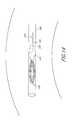
- FIG. 1is a schematic view of a patient's heart with a transseptal sheath deployed through the septum.
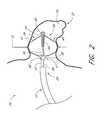
- FIG. 2is a schematic view of a deployment system delivering an implant to the left atrial appendage.
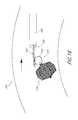
- FIG. 3is a schematic view of a patient's heart with an embolized implant located in the aorta.
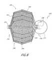
- FIG. 4is a plan view of a LAA implant with a retrievable portion in accordance with one embodiment.
- FIG. 5is an enlarged partial cross-sectional view of the distal end of the implant with the retrievable portion of FIG. 4 .
- FIG. 6is a plan view of a LAA implant with a retrievable portion in accordance with another embodiment.
- FIG. 7is an enlarged partial cross-sectional view of the distal end of the implant with the retrievable portion of FIG. 6 .
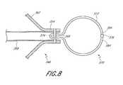
- FIG. 8is an enlarged partial cross-sectional view of the distal end of a LAA implant with a retrievable portion in accordance with another embodiment.
- FIG. 9is a plan view of a LAA implant with a retrievable portion in accordance with another embodiment.
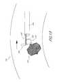
- FIG. 10is a schematic view of a patient's aorta with a sheath disposed near an embolized implant.
- FIG. 11is a schematic view as in FIG. 10 , showing the implant oriented with the distal end facing downstream and retrieval devices extending out of the transeptal sheath.
- FIG. 12is a schematic view as in FIG. 11 , showing the first retrieval device passing through a retrieval portion and the second retrieval device.
- FIG. 13is a schematic view as in FIG. 12 , showing the second retrieval device tightened around the first retrieval device.
- FIG. 14is a schematic view as in FIG. 13 , showing the retrieval devices proximally retracting the implantable device into the transeptal sheath.
- FIG. 15is a schematic view showing a first retrieval device passing through a retrieval portion and a second retrieval device, in accordance with another embodiment.
- FIG. 16is a schematic view as in FIG. 17 , showing the second retrieval device tightened around the first retrieval device.
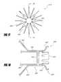
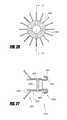
- FIG. 17is an end view of a LAA implant with a retrievable portion in accordance with one embodiment.
- FIG. 18is an enlarged partial cross-sectional view of the implant and retrievable portion of FIG. 17 .
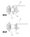
- FIG. 19is a schematic view of an implant with a retrieval portion in accordance with FIGS. 17 and 18 with a retrieval device.
- FIG. 20is a schematic view as in FIG. 19 , showing the retrieval device tightened around the retrievable portion.
- FIG. 21is an end view of a LAA implant with a retrievable portion in accordance with another embodiment.
- FIG. 22is an enlarged partial cross-sectional view of the implant and retrievable portion of FIG. 21 .
- FIG. 23is an enlarged partial cross-sectional view of the implant and retrievable portion of FIGS. 21 and 22 .
- FIG. 24is a schematic view of an implant with a retrieval portion in accordance with FIGS. 21-23 with a retrieval device.
- FIG. 25is a schematic view as in FIG. 24 , showing the retrieval device tightened around the retrievable portion.
- FIG. 26is an end view of a LAA implant with a retrievable portion in accordance with another embodiment.
- FIG. 27is an enlarged partial cross-sectional view of the implant and retrievable portion of FIG. 26 .
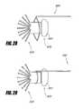
- FIG. 28is a schematic view of an implant with a retrieval portion in accordance with FIGS. 26 and 27 with a retrieval device.
- FIG. 29is a schematic view as in FIG. 28 , showing the retrieval device tightened around the retrievable portion.
- FIG. 30is a schematic view of a retrieval device in accordance with one embodiment.
- FIG. 31is a schematic partial cross-sectional view of a retrieval device in accordance with another embodiment.
- FIG. 32is a schematic partial cross-sectional view as in FIG. 31 , showing the retrieval device partially retracted into a sheath.
- FIG. 33is a schematic view of the distal end of a retrieval device in accordance with another embodiment.
- FIG. 34is a top view of the distal end of a retrieval device in accordance with another embodiment.
- FIG. 35is a side view of the distal end of the retrieval device of FIG. 34 .
- Embodiments of the present inventionrelated to methods and apparatuses for retrieval of implantable devices from the anatomy.
- One such implantable device and systemis known to those of skill in the art as the PLAATOTM system from ev3 Inc.
- PLAATOTM systemfrom ev3 Inc.
- embodiments as described hereinmay be applied to any suitable device, such as for delivering or implanting into other bodily locations or openings. Similar references numerals will be used to designate similar components in the different embodiments. Additionally, some embodiments can include one or more features described in connection with one or more of the embodiments described herein.
- FIG. 1a schematic view of a patient's heart 10 in partial section shows a transseptal sheath 12 having a distal end 14 .
- the distal end 14 of the transseptal sheath 12has breached the septum 18 of the patient's heart 10 and is disposed within the left atrium 16 adjacent the opening 20 of the patient's left atrial appendage 22 (LAA 22 ).
- FIG. 2illustrates a deployment system 24 , having an implant 26 and a delivery system 28 .
- the implant 26may be designed to occlude or contain particles within the LAA 22 and prevent thrombus from forming in, and emboli from originating from, the LAA 22 in a patient with atrial fibrillation.
- the delivery system 28preferably is compatible for use with the transseptal sheath 12 .
- the delivery systempreferably comprises an axially movable core 30 and a control wire 32 .
- the delivery system 28 and implant 26preferably are designed to allow the implant 26 to be positioned, repositioned, and retrieved from the LAA 22 if necessary.
- the implant 26preferably comprises a frame 46 and a membrane 48 (shown in FIG. 4 ).
- the implant 26when expanded preferably extends from a proximal hub 50 at a proximal end 52 increasing in diameter to an apex or apex portion, then decreasing to a distal hub 54 at a distal end 56 .
- the proximal hub 50is coupled with a proximal crosspin 58 .
- the distal hub 54preferably is coupled with a plug or cap 60 .
- a plurality of supports 62extend between a proximal hub 50 and a distal hub 54 .
- sixteen supports 62are provided.
- the precise number of supports 62can be modified, depending upon the desired physical properties of the implant 26 as will be apparent to those of skill in the art in view of the disclosure herein, without departing from the present invention.
- the supports 62comprise a metal such as stainless steel, nitinol, Elgiloy, or others which can be determined through routine experimentation by those of skill in the art.
- the frame 46preferably is constructed of self-expanding nitinol supports. Wires having a circular or rectangular cross-section may be utilized depending upon the manufacturing technique. In one embodiment, rectangular cross section supports are cut such as by known laser cutting techniques from tube stock, a portion of which forms the hubs 50 and 54 .
- the implant 26preferably comprises anchors 64 that extend from the frame 46 when the implant 26 is expanded. At least some of the supports 62 , and, preferably, each support 62 , is provided with one or two or more barbs 64 . In one embodiment, each support 62 has three barbs 64 . As illustrated in FIG. 4 , the implant 26 is in its enlarged orientation, such as for occluding a left atrial appendage or other body cavity or lumen. In this orientation, each of the barbs 46 projects generally radially outwardly from the implant 26 , and is inclined in the proximal direction. This is to inhibit proximal migration of the implant out of the left atrial appendage. One or more barbs may also be inclined distally.
- distalrefers to the direction into the left atrial appendage
- proximalrefers to the direction from the left atrial appendage into the heart.
- the barbs 64 and corresponding support 62are cut from a single ribbon, sheet or tube stock, the barb 64 will incline radially outwardly at approximately a tangent to the curve formed by the support 46 .
- the distal end 56 of the implant 26is provided with a plug or cap 60 .
- the plug 60comprises an atraumatic tip, such that contact between the atraumatic tip and the inside surface of the LAA 22 does not cause significant damage to the LAA 22 .
- the plug 60may be attached to a distal end of a distal guide tube 66 , described in greater detail below.
- the plug 60may be secured to the guide tube 66 and implant 26 in any of a variety of ways, depending upon the various construction materials. For example, any of a variety of metal bonding techniques such as a welding, brazing, interference fit such as threaded fit or snap fit, may be utilized. Alternatively, any of a variety of bonding techniques for dissimilar materials may be utilized, such as adhesives, and various molding techniques.
- the plug 60is composed of PEBAX.
- the membrane 48preferably is constructed of a fabric covering, such as one made of ePTFE, or an ePTFE/PE laminate.
- a PE meshpreferably is placed against the supports 62 , with one sheet of ePTFE preferably placed over the PE mesh and another sheet of ePTFE preferably placed on an opposite side of the supports 62 .
- the membrane 48preferably is heated on both sides causing the PE to melt into both sheets of ePTFE, thereby surrounding a portion of the frame 46 .
- the nitinol supportsallow the implant 26 to self-expand in the appendage 22 , covering the orifice with the laminated fabric.
- the porous ePTFE/PE laminationfacilitates rapid endothelialization and healing.
- the membrane 48preferably covers at least a proximal face of the device.
- the core 30may comprise any of a variety of structures which has sufficient lateral flexibility to permit navigation of the vascular system, and sufficient axial column strength to enable reduction of the implant 26 to its reduced crossing profile. Any of a variety of structures such as hypotube, solid core wire, “bottomed out” coil spring structures, or combinations thereof may be used, depending upon the desired performance of the finished device.
- the core 30comprises stainless steel tubing.
- the distal guide tube 66extends proximally from the distal hub 54 .
- the guide tube 66receives the distal end of core 30 within a recess or lumen defined by the guide tube 66 .
- proximal retraction of the core 30enables the implant 26 to radially enlarge under its own bias to fit the surrounding tissue structure.
- the guide tube 66may be a section of tubing such as metal hypotube, which is attached at the distal end 56 of the implant and extends proximally within the implant 26 .
- the guide tube 66preferably extends a sufficient distance in the proximal direction to inhibit buckling or prolapse of the core 30 when distal pressure is applied to the core to reduce the profile of the implant 26 .
- the guide tube 66should not extend proximally a sufficient distance to interfere with the opening of the implant 26 .
- the guide tube 66may operate as a limit on distal axial advancement of the proximal end 50 of implant 26 .
- the guide tube 66preferably does not extend sufficiently far proximally from the distal end 56 to interfere with optimal opening of the implant 26 .
- the specific dimensionsare therefore relative, and will be optimized to suit a particular intended application.
- the implant 26has an implanted outside diameter within the range of from about 5 mm to about 45 mm, and an axial implanted length within the range of from about 5 mm to about 45 mm.
- the guide tube 66may have an overall length of about 3 mm to about 35 mm, and an outside diameter of about 0.095 inches.
- the implant 26is shown expanded within LAA 22 in FIG. 2 .
- the implant 26preferably meets the following acceptance criteria, associated with the assessment techniques listed below, prior to being released.
- the assessment techniques to be evaluatedpreferably include 1) residual compression; 2) implant location; 3) anchor engagement; 4) seal quality; and 5) stability.
- the implant diameter ⁇as measured by fluoroscopic imaging, preferably is less than the maximum expanded diameter of the implant 26 .
- the proximal sealing surface of the implant 26preferably is positioned between the LAA 22 ostium and sources of thrombus formation (pectinates, secondary lobes, etc.) (preferably imaged in at least two views).
- the implant frame 46preferably is positioned within the LAA 22 so as to completely engage a middle row of anchors 64 in an LAA 22 wall (preferably imaged in at least two views).
- the contrast injectionspreferably show leakage rated no worse than mild (preferably defined as a flow of contrast media, well defined, and filling one-third of the LAA 22 during a proximal injection over a period of up to about five ventricular beats, preferably imaged in at least two views).
- the stability of the implant 26preferably is verified in several views using fluoroscopy and echocardiography.
- the implant 26preferably is released from the delivery system 28 by decoupling, under fluoroscopy, the axially movable core 30 and control line 32 from the implant 26 .
- Further details regarding LAA devices and related methodsare disclosed in U.S. Pat. No. 6,152,144, filed Nov. 6, 1998; U.S. Pat. No. 7,128,073, filed Nov. 8, 1999; U.S. Pat. No. 7,044,134, filed Oct. 19, 2001; and U.S. patent application Ser. No. 10/642,384, filed Aug. 15, 2003 and published as U.S. Pat. Pub. No. 2005/0038470. The entirety of each of these is hereby incorporated by reference.
- embolization of the implantable device 26may occur.
- the implantable device 26embolizes, it may be carried by the blood flow from the left atrium 16 through the mitral valve 34 and into the left ventricle 36 . From the left ventricle 36 the implant 26 can then be carried through the aortic valve 38 and into the aorta 40 . The implant may become lodged in the aortic arch 42 or the descending aorta 44 . The implant may also lodge at other locations.
- a sheathe.g., an outer sheath, transseptal sheath, or a delivery sheath
- anchors 64 protruding from the implant 26do not snag, catch, rip, pinch, pierce, cut and/or otherwise affect the inside wall of the anatomical structure.
- the implantmay be a stent, a cage, a filter, a coil, a clip, or any other implantable support structure.
- a retrieval portionis connected to the implant to facilitate capture of the implant and allow the device to be pulled proximally into a retrieval sheath for removal from the body. It will be appreciated that retrieval portions may be incorporated with any of the implants described herein, including implants in the patents and applications incorporated by reference.
- the retrieval portionmay be any device that can be coupled to a retrieval catheter to retrieve the implantable device.
- the retrieval portionpreferably is located in a position that has no negative interactions with the implant anchoring and sealing structures and which presents no additional device handling complexity for the device user. This will reduce regulatory approval needs for the implantable device, potentially avoiding a need for requalification with respect to safety and efficacy.
- the retrieval portionpreferably does not affect expansion or collapse of the implant.
- One suitable locationis distal to the anchoring and sealing structures, where the retrieval portion neither affects the method of implant delivery, expansion, nor collapse.
- a retrieval portion 70is connected to the implant 26 .
- the implant 26may comprise a frame 46 and a membrane 48 .
- the frame 46may comprise a proximal hub 50 at a proximal end 52 , a distal hub 54 at a distal end 56 , and a plurality of supports 62 extending between the proximal hub 50 and the distal hub 54 .
- a plurality of anchors 64may extend radially and proximally from the supports 62 .
- a distal guide tube 66may be connected to the frame 46 at the distal end 56 and preferably extends in a proximal direction.
- the distal guide tube 66may be connected to the frame 46 by a pin 68 , a cap 60 , or both.
- the retrieval portion 70may be connected to the implant 26 at the distal end 56 , a proximal end 52 , or both. In one embodiment, the retrieval portion 70 may be positioned distal to the anchors 64 on the implant 26 .
- the retrieval portion 70may comprise a loop 72 .
- the loop 72may be generally circular and may range in diameter from about 2 mm or less to about 25 mm or more. In one embodiment the loop 72 is 7.5 mm in diameter. The loop 72 may be about 0.3 mm or less to about 1 mm or more thick. In one embodiment, the loop 72 is 0.5 mm thick.
- the loopis comprised of NITINOL stranded wire having 7 helically wound strands each with a strand diameter of 0.0013′′, the stranded wire running through the center of a gold coiled wire having a wire diameter of 0.001′′ and a coil outside diameter of 0.006′′.
- the loop 72may extend distally from the distal hub 54 .
- the loop 72may be enclosed within the LAA occlusion volume 74 (shown in FIG. 2 ) when implant 26 is expanded within LAA 22 and should, therefore, not adversely affect the criteria for proper placement described above.
- the loop 72may be connected to the implant 26 by a segment 74 of loop 72 , as shown in FIG. 5 .
- the distal hub 54may have passages 78 .
- the passages 78may be holes and may be located proximal to the cap 68 .
- the pin 68may have passages 80 .
- the loop segment 74may extend through the passages 78 in the distal hub 54 and the passages 80 in pin 68 , between the hub 54 and the distal guide tube 66 , and around the end of distal guide tube 66 . In this fashion, rotational and translational movement of the loop 72 relative to the implant 226 is restricted to maintain the spacing of the loop 72 from the implant 26 .
- the retrieval portion 70preferably is light and flexible, and atraumatic with respect to the inside wall of the cavity, vessel and/or organ into which it is provided.
- the retrieval portion 70preferably is able to withstand strong tension forces provided during implant retrieval.
- the retrieval portion 70 of the implantable devicepreferably is compliant so it does not affect implant fit with the cavity, organ or lumen (e.g., the left atrial appendage) into which it is delivered and so that it may be collapsed into a delivery catheter or sheath.
- the retrieval portion 70may be made from any material suitable for implantation within the body.
- the retrieval portioncan be made from metal, stainless steel, gold, platinum, tungsten, other radiopaque alloys, plastic, string, NYLON, a combination of such materials, or any other suitable material in monofilament, stranded, or cabled forms.
- the retrieval loopmay be self-expanding and made from stranded NITINOL (e.g., a nickel titanium alloy) and covered in a gold plated tungsten coil. The loop may be closed in some embodiments by a weld or solder joint 76 .
- a retrieval portion 270is connected to an implant 226 .
- the retrieval portion 270may comprise a loop 272 extending distally from implant 226 .
- the distal guide tube 266may comprise a pair of generally transverse passages 282 .
- the loop 272may pass between the supports 262 and through the passages 282 in the distal guide tube 266 to connect the loop 272 to the implant 226 and restrict translational movement of the loop 272 relative to the implant 226 in either a proximal or a distal direction. Interference between the loop 272 and the supports 262 inhibits rotational movement of the loop 272 relative to the supports 262 to maintain the spacing of the loop 272 from the implant 226 .
- a retrieval portion 370is connected an implant 326 in accordance with another embodiment, shown in FIG. 8 .
- the retrieval portion 370comprises a loop 372 .
- the loop 372has a segment 374 that extends into the distal guide tube 366 and around a crosspin 368 .
- the ends 384 of the loop 372may be joined at a joint 376 by welding, soldering, or other attachment joining method known to those of skill in the art.
- the retrieval portionmay be attached to the frame by any other attachment technique known to those of skill in the art, such as by an adhesive, mechanical lock, pin, threads, clip, weld, solder, laser bond or weld, or friction coupling.
- the ends 384 of the loop 372may be located at a proximal end of the loop and welded, soldered, or otherwise attached directly to a distal end of the implant by any method known to those of skill in the art.
- the retrieval portionmay be integrally formed with the frame.
- the retrieval portioncan be formed from the material of the frame by laser cutting a tube.
- a retrieval portion 470may comprise a plurality of loops 472 attached to the distal end 456 of implant 426 .
- loops 472For example, 2, 3, 4, 5, or more loops may be provided.
- a retrieval portioncomprising a retrieval loop has been prototyped and animal tested.
- the prototyped devicedid not affect implantation ability.
- the ability to retrieve an embolized implantwas tested in a narrow animal aortic overflow tract, which prevented embolization beyond the aortic valve.
- Bench testing in glass aortic bifurcation modelshowed quick and effective snaring and retrieval of the implantable device utilizing the loop and two snares of a retrieval catheter.
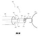
- FIGS. 10-14A method for retrieving an implant having a retrievable portion is illustrated in FIGS. 10-14 .
- the implantable devicein the unlikely event that embolization of the implantable device occurs, the implantable device, substantially as described above, may be present in the left atrium, left ventricle, aorta, or other location.
- an implant 526 with a retrieval portion 570may be present in the aorta 540 .
- the retrieval portion 570may comprise a loop 572 .
- the implant 526may have become oriented such that the proximal end 552 is located downstream from the distal end 556 , as indicated by the arrow 573 in FIG. 10 .
- the method as followsmay be performed under fluoroscopy or any other visualization technique.
- a sheath 586is introduced through the vasculature and is positioned near the implant 526 , as shown in FIG. 10 .
- the sheath 586may be introduced through the femoral artery.
- the sheathmay be introduced through the femoral vein, advanced through the right atrium, inserted through the intraatrial septum, and directed to the left ventricle.
- the sheath 586may be introduced through the iliac artery, brachial artery, popliteal artery, radial artery, or other percutaneous access sites.
- the sheath 586preferably has a linear or non-curved distal end 588 .
- the sheath 586may be a transseptal sheath, such as transseptal sheath 12 described above.
- the sheathhas an inner diameter of 12 French.
- the sheathmay have an inner diameter ranging from about 9 French or less to about 25 French or more.
- one or more retrieval devices 590are delivered through the sheath 586 .
- the retrieval device 590may be a snare, grasper, hook, loop, or biopsy catheter or any device capable of grasping the retrieval portion 590 .
- the retrieval device 590may be Amplatz GOOSE NECK® Snare produced by ev3 Inc.
- the retrieval device 590may be used to manipulate the implant 526 within the aorta 540 such that the end 556 coupled to the retrieval portion 570 is next to the retrieval devices 590 and the sheath 586 , as shown in FIG. 11 .
- percutaneous accessis accomplished on the side contralateral to retrieval device access and a snare catheter is introduced to the vicinity of the implant and used to stabilize the implant while a retrieval device 590 is appropriately positioned.
- the distal end 556preferably is then facing downstream.
- the one or more retrieval devices 590may be coupled to the retrieval portion 570 of the implantable device 526 .
- a first retrieval device 590may be placed through the loop 572 .
- a second retrieval device 590 ′may be placed over the first retrieval device 590 .
- the second retrieval device 590 ′may be tightened onto the first retrieval device 590 , as shown in FIG. 13 .
- the first retrieval device 590 and second retrieval device 590 ′may be retracted proximally into the sheath 586 pulling the implant 526 into the sheath 586 by the loop 572 , as illustrated in FIG. 14 .
- the implant 526preferably collapses as it is drawn into the sheath 586 .
- anchors 564 on implant 526preferably face away from sheath 586 such that as the implant 526 is retracted proximally the anchors 564 do not snag, catch, tear, or rip the sheath 586 or the wall of the aorta 540 .
- a first retrieval device 590may be a stiff wire or small bore catheter, as illustrated in FIGS. 15 and 16 .
- the first retrieval device 590 comprising a stiff wire or small bore cathetermay be placed through the loop 572 .
- a second retrieval device 590 ′ comprising a snaremay be placed over the first retrieval device 590 comprising a stiff wire or small bore catheter.
- the snare 590 ′may be tightened onto the stiff wire or small bore catheter 590 , as shown in FIG. 16 .
- the retrieval devices 590 and 590 ′may be retracted proximally to pull the implant 526 into the sheath 586 .
- the retrieval devicemay comprise a biopsy catheter.
- the biopsy cathetermay be used to grasp the retrievable portion.
- the biopsy cathetermay be retracted proximally into the sheath once the biopsy catheter has grasped the retrievable portion.
- a retrievable portion 670may comprise a plurality of extensions 692 , each extending between a first end 694 and a second end 696 .
- the retrieval portion 670may comprise 2 to 16 or more extensions 692 .
- the retrieval portion 670may comprise 8 extensions 692 .
- the first ends 694 of extensions 692may be attached to an implant 626 .
- the first ends 694may be attached to a distal guide tube 666 .
- the extensions 692 and the distal guide tube 666may be integrally formed, as shown in FIG. 18 .
- distal guide tube 666 and extensions 692may be made from tube stock by known laser cutting techniques.
- the extensions 692may be attached to the distal guide tube 666 by any attachment technique known to those of skill in the art, such as by an adhesive, mechanical lock, pin, threads, clip, weld, solder, laser bond or weld, or friction coupling. In other embodiments, the extensions may be attached to the distal hub 654 or the supports 662 of implant 626 .
- the distal guide tube 666may be connected to the distal hub 654 by a pin 668 .
- the extensions 692may extend distally from a distal end 656 of the implant 626 , as illustrated in FIG. 18 .
- the extensions 692may distally extend about 0.5 mm or less to about 2 mm or more from the distal hub 654 . In one embodiment, the extensions 692 may distally extend about 1.25 mm from the distal hub 654 .
- the extensions 692may be generally S-shaped and may extend radially outward.
- the extensions 692may extend radially outward about 0.5 mm or less to about 2 mm or more from the distal hub 654 . In one embodiment, the extensions 692 may extend radially outward about 1.25 mm from the distal hub 654 .
- the second end 696 of the extensions 692may point radially inward to prevent trauma to the anatomy should it be contacted by the extensions 692 .
- the extensions 692may be comprised of metal, stainless steel, gold, plastic, NYLON, a combination of such materials, or any other material suitable for implantation within the body.
- the extensions 692may be made from a self-expanding material such as NITINOL with a hole drilled therein and a radiopaque gold rivet extending through the hole and enlarged outside both ends of the hole so as to fix the rivet to the extension.
- the extensions 692may be resilient and may be compressed radially inwardly for insertion or retraction through a sheath.
- FIGS. 19 and 20A method of coupling a retrieval device 690 to the retrieval portion 670 is illustrated schematically in FIGS. 19 and 20 .
- the retrieval device 690such as a snare or loop may be disposed around the retrieval portion 670 , as shown in FIG. 19 .
- the retrieval device 690may then be tightened around the retrieval portion 670 , as illustrated in FIG. 20 .
- the retrieval device 690may retract the implant 626 into a sheath by pulling the retrieval portion 670 .
- a retrievable portion 770may comprise a plurality of extensions 792 extending between first ends 794 and second ends 796 .
- the retrieval portion 770may comprise 3 extensions 792 .
- the first ends 794 of extensions 792may be attached to an implant 726 .
- the first ends 794may be attached to or integral with a distal guide tube 766 .
- the distal guide tube 766may be connected to the distal hub 754 by a pin 768 .
- the extensions 792may extend distally from a distal end 756 of the implant 726 , as illustrated in FIG. 22 .
- the extensions 792may distally extend about 0.5 mm or less to about 2 mm or more from the distal hub 754 in their natural state. In one embodiment, the extensions 792 may distally extend about 2 mm from the distal hub 754 .
- the extensions 792may be generally S-shaped and may extend transversely across the distal guide tube 766 .
- the extensions 792may extend transversely about 2 mm or less to about 6 mm or more. In one embodiment, the extensions 792 may extend transversely about 4 mm.
- the second end 796 of extensions 792may point radially inward when deployed to prevent trauma to the anatomy near where the implant 726 is deployed.
- the extensions 792may be resilient and self-expanding and may be urged into a generally straight shape by an axially movable core 730 during placement of the implant 726 to permit the implant 726 with the retrievable portion 770 to be inserted through a sheath or catheter.
- the axially movable core 730may include a slot 798 to allow the core 730 to extend past pin 768 .
- FIGS. 24 and 25A method of coupling a retrieval device 790 to the retrieval portion 770 is illustrated schematically in FIGS. 24 and 25 .
- the retrieval device 790such as a snare or loop may be disposed around the retrieval portion 770 , as shown in FIG. 24 .
- the retrieval device 790may then be tightened around the retrieval portion 770 , as illustrated in FIG. 20 .
- the retrieval device 790may retract the implant 726 into a sheath by pulling the retrieval portion 770 .
- a retrievable portion 870may comprise a plurality of extensions 892 extending between first ends 894 and second ends 896 .
- the retrieval portion 870may comprise 8 extensions 892 .
- the first ends 894 of extensions 892may be attached to an implant 826 .
- the first ends 894may be attached to a distal guide tube 866 .
- the distal guide tube 866may be connected to the distal hub 854 by a pin 868 .
- the extensions 892may extend distally from a distal end 856 of the implant 826 , as illustrated in FIG. 27 .
- the extensions 892may distally extend about 0.5 mm or less to about 4 mm or more from the distal hub 854 . In one embodiment, the extensions 892 may distally extend about 2 mm from the distal hub 854 .
- the extensions 892may be generally J-shaped and may curve radially outward.
- the extensions 892may be made from a self-expanding material, such as NITINOL.
- the extensions 892may extend radially outward about 0.25 mm or less to about 2 mm or more. In one embodiment, the extensions 892 may extend radially outward about 0.5 mm.
- the second ends 896 of extensions 892may comprise an atraumatic tip.
- the second ends 896may be curved outwardly and proximally, and may be generally covered by a cap 860 .
- the cap 860may be made of polyethylene or other atraumatic material. In one embodiment, the cap 860 is composed of PEBAX.
- FIGS. 28 and 29A method of coupling a retrieval device 890 to the retrieval portion 870 is illustrated schematically in FIGS. 28 and 29 .
- the retrieval device 890such as a snare or loop may be disposed around the retrieval portion 870 , as shown in FIG. 28 .
- the retrieval device 890may then be tightened around the retrieval portion 870 , as illustrated in FIG. 29 .
- the retrieval device 890may retract the implant 826 into a sheath by pulling the retrieval portion 870 .
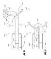
- FIG. 30illustrates a retrieval device 990 in accordance with one embodiment.
- the retrieval device 990may be connected to a conventional snare 901 .
- the snare 901comprises a snare catheter 903 and a snare loop 905 .
- the retrieval device 990comprises an adapter 907 .
- the adapter 907may comprise a cylindrical body 909 and a hook 911 .
- the cylindrical body 909may have a proximal opening 913 at a proximal end 915 and a distal opening 917 at a distal end 919 .
- the hook 911may be attached to the distal end 919 of the cylindrical body 909 .
- the cylindrical body 909 and the hook 911may be made from metal, such as NITINOL or stainless steel and tipped with radiopaque material.
- the cylindrical body 909may be made of a different material than hook 911 .
- the cylindrical body 909 and the hook 911may be made of NITINOL and be integrally formed.
- the hook 911may be attached to the cylindrical body 909 by any of a variety of metal bonding techniques such as a welding, brazing, interference fit such as threaded fit or snap fit, may be utilized.
- the hook 911may be made of stainless steel and soldered to the body 909 .
- any of a variety of bonding techniques for dissimilar materialsmay be utilized, such as adhesives, and various molding techniques.
- the adapter 907may be connected to the snare 901 as illustrated in FIG. 30 .
- the snare loop 905may extend through the cylindrical body 909 and around the hook 911 .
- the snare catheter 903may be advanced distally relative to the snare loop 905 to tighten the snare 901 onto the adapter 907 .
- the proximal openingmay be large enough to permit the snare catheter 903 to be disposed within the body 909
- the distal opening 917 of the body 909may be smaller than the proximal opening 913 such that the snare catheter 903 is not permitted to pass beyond the distal opening 917 .
- the proximal opening 913may be small enough not to permit the snare catheter from being disposed within the body 909 .
- the outer diameter of the cylindrical body 909may range from about 5 French or less to about 12 French or more. In one embodiment, the outer diameter of body 909 is about 11 French.
- the hookmay be wider or narrower than the body 909 but should be narrower than the luminal diameter of sheath 986 . In one embodiment, the hook 911 is narrower than the body 909 so that the hook 911 is less likely to catch on a sheath or catheter when retracted therein.
- the adapter 907may be used in conjunction with the general method for retrieving an implantable device with a retrieval portion 970 .
- the adapter 907 and snare 901are preferably connected as described above before being inserted into the patient through the sheath.
- the adapter 907may be coupled to the retrieval portion 970 by disposing the hook 911 around the retrieval portion 970 .
- the adapter 907may then be retracted proximally into the sheath 986 with the retrieval portion.
- FIG. 31illustrates a retrieval device 1090 in accordance with one embodiment.
- the retrieval device 1090may be connected to a conventional snare 1001 .
- the snare 1001comprises a snare catheter 1003 and a snare loop 1005 .
- the retrieval device 1090comprises an adapter 1007 .
- the adapter 1007may comprise a tube 1021 extending between a proximal end 1023 and a distal end 1025 , an articulation hole 1027 , and snare attachment element 1029 .
- the tube 1021may also comprise a curved section 1037 near the distal end 1025 .
- the outer diameter of tube 1021may range from about 4 French or less to about 6 French or more. In one embodiment, the outer diameter of the tube 1021 is about 5 French.
- the inner diameter of tube 1021is preferably small enough to prevent the snare catheter 1003 from being advanced within the tube 1021 when the snare 1001 is tightened.
- the tube 1021may be made of a resilient metal or plastic. In one embodiment, the tube 1021 may be made of NITINOL.
- the articulation hole 1027facilitates and controls folding of the tube 1021 , as will be described below.
- the articulation hole 1027may be range is size from about 0.5 French or less to about 3 French or more in diameter. In one embodiment, the articulation hole 1027 may be about 2 French in diameter.
- the articulation hole 1027may be located from about 3 mm or less to about 5 mm or more from the distal end 1025 of the tube 1021 and is located on the inner bend surface of tube 1021 to facilitate tube folding. In one embodiment, the articulation hole 1027 may be located about 4 mm from the distal end 1025 of the tube 1021 .
- the snare attachment element 1029allows the snare loop 1005 to be attached to the tube 1021 .
- the snare attachment element 1029may comprise a hole 1031 near the distal end 1025 of the tube 1021 .
- the hole 1031is preferably large enough to permit a snare loop 1005 to pass through it.
- the tube 1021may be connected to the snare 1001 by passing the snare loop 1005 through the proximal end 1023 of the tube 1021 , out the hole 1031 , and around the distal end 1025 of the tube 1021 , as illustrated in FIG. 31 .
- the tube 1021may have two snare attachment holes 1031 near the distal end 1025 .
- the snare loop 1005may be extend out the distal end 1025 of the tube 1021 , return along the exterior of the tube 1021 , extend transversely across the tube 1021 through both of the holes 1031 , and extend around the tube 1021 .
- the snare attachment element 1029may comprise a pair of generally diametrically opposed wings 1033 and slots 1035 .
- Each wing 1033may be made by laser cutting generally U- or C-shaped slot 1035 in the tube 2021 such that the distal end of the wing 1033 remains connected to the tube 1021 .
- the wings 1033may be flared generally radially outward to permit passage of the snare loop 1005 behind the wings 1033 .
- the snare loop 1005may be extend out the distal end 1025 of the tube 1021 , return along the exterior of the tube 1021 , and extend generally around the tube 1021 passing through the slots 1035 .
- the adapter 1007may be used in conjunction with the general method for retrieving an implantable device with a retrieval portion 1070 .
- the adapter 1007may be coupled to the retrieval portion 1070 by disposing the distal end 1025 around or through the retrieval portion 1070 as dictated by the shape of the retrieval portion 1070 .
- the snare 1001may be tightened. As the snare 1001 is tightened the snare loop 1005 pulls on the distal end 1025 of the tube 1021 , causing the tube 1021 to bend, as shown in FIG. 32 . The bending of the tube 1021 will tend to be localized near the articulation hole 1027 .
- the articulation hole 1027will help control tube 1021 bending as the snare 1001 is tightened.
- Embodiments of the inventionare used to treat other bodily openings, lumen and cavities, besides the left atrial appendage.
- implantable devices for treating any heart opening or defectsuch as a patent foramen ovale (PFO), atrial septal defect (ASD), ventricular septal defect (VSD), patent ductus arteriosus (PDA), aneurysm and aortico-pulmonary window are retrievable according to any of the methods and devices described above.
Landscapes
- Health & Medical Sciences (AREA)
- Surgery (AREA)
- Life Sciences & Earth Sciences (AREA)
- Biomedical Technology (AREA)
- Medical Informatics (AREA)
- Vascular Medicine (AREA)
- Veterinary Medicine (AREA)
- Engineering & Computer Science (AREA)
- Public Health (AREA)
- Heart & Thoracic Surgery (AREA)
- Nuclear Medicine, Radiotherapy & Molecular Imaging (AREA)
- Molecular Biology (AREA)
- Animal Behavior & Ethology (AREA)
- General Health & Medical Sciences (AREA)
- Reproductive Health (AREA)
- Cardiology (AREA)
- Orthopedic Medicine & Surgery (AREA)
- Surgical Instruments (AREA)
- Prostheses (AREA)
Abstract
Description
Claims (4)
Priority Applications (2)
| Application Number | Priority Date | Filing Date | Title |
|---|---|---|---|
| US11/607,638US9034006B2 (en) | 2005-12-01 | 2006-12-01 | Method and apparatus for retrieving an embolized implant |
| US14/708,757US20150238197A1 (en) | 2005-12-01 | 2015-05-11 | Method and apparatus for retrieving an embolized implant |
Applications Claiming Priority (2)
| Application Number | Priority Date | Filing Date | Title |
|---|---|---|---|
| US74126205P | 2005-12-01 | 2005-12-01 | |
| US11/607,638US9034006B2 (en) | 2005-12-01 | 2006-12-01 | Method and apparatus for retrieving an embolized implant |
Related Child Applications (1)
| Application Number | Title | Priority Date | Filing Date |
|---|---|---|---|
| US14/708,757ContinuationUS20150238197A1 (en) | 2005-12-01 | 2015-05-11 | Method and apparatus for retrieving an embolized implant |
Publications (2)
| Publication Number | Publication Date |
|---|---|
| US20070162048A1 US20070162048A1 (en) | 2007-07-12 |
| US9034006B2true US9034006B2 (en) | 2015-05-19 |
Family
ID=38233679
Family Applications (2)
| Application Number | Title | Priority Date | Filing Date |
|---|---|---|---|
| US11/607,638Active2031-08-18US9034006B2 (en) | 2005-12-01 | 2006-12-01 | Method and apparatus for retrieving an embolized implant |
| US14/708,757AbandonedUS20150238197A1 (en) | 2005-12-01 | 2015-05-11 | Method and apparatus for retrieving an embolized implant |
Family Applications After (1)
| Application Number | Title | Priority Date | Filing Date |
|---|---|---|---|
| US14/708,757AbandonedUS20150238197A1 (en) | 2005-12-01 | 2015-05-11 | Method and apparatus for retrieving an embolized implant |
Country Status (1)
| Country | Link |
|---|---|
| US (2) | US9034006B2 (en) |
Cited By (24)
| Publication number | Priority date | Publication date | Assignee | Title |
|---|---|---|---|---|
| US20150094754A1 (en)* | 2013-10-01 | 2015-04-02 | Cook Medical Technologies Llc | Filter device, system, and method |
| US20150238197A1 (en)* | 2005-12-01 | 2015-08-27 | Atritech, Inc. | Method and apparatus for retrieving an embolized implant |
| US10617425B2 (en) | 2014-03-10 | 2020-04-14 | Conformal Medical, Inc. | Devices and methods for excluding the left atrial appendage |
| US10722240B1 (en) | 2019-02-08 | 2020-07-28 | Conformal Medical, Inc. | Devices and methods for excluding the left atrial appendage |
| US11026695B2 (en) | 2016-10-27 | 2021-06-08 | Conformal Medical, Inc. | Devices and methods for excluding the left atrial appendage |
| US11331140B2 (en) | 2016-05-19 | 2022-05-17 | Aqua Heart, Inc. | Heated vapor ablation systems and methods for treating cardiac conditions |
| US11357484B2 (en) | 2017-03-30 | 2022-06-14 | Medtronic, Inc. | Medical device retrieval with multiple snares |
| US11399842B2 (en) | 2013-03-13 | 2022-08-02 | Conformal Medical, Inc. | Devices and methods for excluding the left atrial appendage |
| US11426172B2 (en) | 2016-10-27 | 2022-08-30 | Conformal Medical, Inc. | Devices and methods for excluding the left atrial appendage |
| US11517319B2 (en) | 2017-09-23 | 2022-12-06 | Universität Zürich | Medical occluder device |
| US11540838B2 (en) | 2019-08-30 | 2023-01-03 | Boston Scientific Scimed, Inc. | Left atrial appendage implant with sealing disk |
| US11589920B2 (en) | 2008-10-06 | 2023-02-28 | Santa Anna Tech Llc | Catheter with a double balloon structure to generate and apply an ablative zone to tissue |
| US11717303B2 (en) | 2013-03-13 | 2023-08-08 | Conformal Medical, Inc. | Devices and methods for excluding the left atrial appendage |
| US11903589B2 (en) | 2020-03-24 | 2024-02-20 | Boston Scientific Scimed, Inc. | Medical system for treating a left atrial appendage |
| US11944315B2 (en) | 2019-09-26 | 2024-04-02 | Universität Zürich | Left atrial appendage occlusion devices |
| US11944314B2 (en) | 2019-07-17 | 2024-04-02 | Boston Scientific Scimed, Inc. | Left atrial appendage implant with continuous covering |
| US12144508B2 (en) | 2019-02-08 | 2024-11-19 | Conformal Medical, Inc. | Devices and methods for excluding the left atrial appendage |
| US12318092B2 (en) | 2021-06-22 | 2025-06-03 | Boston Scientific Scimed, Inc. | Left atrial appendage implant |
| US12329500B2 (en) | 2020-11-30 | 2025-06-17 | Boston Scientific Scimed, Inc. | Implantable passive mean pressure sensor |
| US12349918B2 (en) | 2021-09-08 | 2025-07-08 | Boston Scientific Scimed, Inc. | Multi-sharpness split top soft tissue anchors |
| US12364537B2 (en) | 2016-05-02 | 2025-07-22 | Santa Anna Tech Llc | Catheter with a double balloon structure to generate and apply a heated ablative zone to tissue |
| US12383278B2 (en) | 2021-07-08 | 2025-08-12 | Boston Scientific Scimed, Inc. | Left atrial appendage closure device |
| US12383201B2 (en) | 2021-02-03 | 2025-08-12 | Boston Scientific Scimed, Inc. | Medical system for treating a left atrial appendage |
| US12402885B2 (en) | 2017-09-23 | 2025-09-02 | Universität Zürich | Medical occlusion device |
Families Citing this family (103)
| Publication number | Priority date | Publication date | Assignee | Title |
|---|---|---|---|---|
| US7128073B1 (en) | 1998-11-06 | 2006-10-31 | Ev3 Endovascular, Inc. | Method and device for left atrial appendage occlusion |
| US8388672B2 (en) | 1999-08-09 | 2013-03-05 | Cardiokinetix, Inc. | System for improving cardiac function by sealing a partitioning membrane within a ventricle |
| US10307147B2 (en) | 1999-08-09 | 2019-06-04 | Edwards Lifesciences Corporation | System for improving cardiac function by sealing a partitioning membrane within a ventricle |
| US7674222B2 (en) | 1999-08-09 | 2010-03-09 | Cardiokinetix, Inc. | Cardiac device and methods of use thereof |
| US9694121B2 (en) | 1999-08-09 | 2017-07-04 | Cardiokinetix, Inc. | Systems and methods for improving cardiac function |
| US8529430B2 (en) | 2002-08-01 | 2013-09-10 | Cardiokinetix, Inc. | Therapeutic methods and devices following myocardial infarction |
| US8500795B2 (en) | 1999-08-09 | 2013-08-06 | Cardiokinetix, Inc. | Retrievable devices for improving cardiac function |
| US9078660B2 (en) | 2000-08-09 | 2015-07-14 | Cardiokinetix, Inc. | Devices and methods for delivering an endocardial device |
| US20060030881A1 (en)* | 2004-08-05 | 2006-02-09 | Cardiokinetix, Inc. | Ventricular partitioning device |
| US8398537B2 (en) | 2005-06-10 | 2013-03-19 | Cardiokinetix, Inc. | Peripheral seal for a ventricular partitioning device |
| US9332992B2 (en) | 2004-08-05 | 2016-05-10 | Cardiokinetix, Inc. | Method for making a laminar ventricular partitioning device |
| US10064696B2 (en) | 2000-08-09 | 2018-09-04 | Edwards Lifesciences Corporation | Devices and methods for delivering an endocardial device |
| US9332993B2 (en) | 2004-08-05 | 2016-05-10 | Cardiokinetix, Inc. | Devices and methods for delivering an endocardial device |
| US8961541B2 (en) | 2007-12-03 | 2015-02-24 | Cardio Vascular Technologies Inc. | Vascular closure devices, systems, and methods of use |
| US8992567B1 (en) | 2001-04-24 | 2015-03-31 | Cardiovascular Technologies Inc. | Compressible, deformable, or deflectable tissue closure devices and method of manufacture |
| US20080109030A1 (en) | 2001-04-24 | 2008-05-08 | Houser Russell A | Arteriotomy closure devices and techniques |
| WO2009032834A1 (en) | 2007-09-07 | 2009-03-12 | Crusader Medical Llc | Percutaneous permanent retrievable vascular filter |
| US8795318B2 (en)* | 2007-09-07 | 2014-08-05 | Merit Medical Systems, Inc. | Percutaneous retrievable vascular filter |
| DE102007043830A1 (en) | 2007-09-13 | 2009-04-02 | Lozonschi, Lucian, Madison | Heart valve stent |
| AU2008360983A1 (en)* | 2008-08-25 | 2010-03-04 | Cardiokinetix, Inc. | Retrievable cardiac devices |
| US20100114135A1 (en)* | 2008-10-31 | 2010-05-06 | Scott Wilson | Devices and methods for temporarily opening a blood vessel |
| EP2416711A4 (en) | 2009-04-09 | 2017-06-07 | Cardiovascular Technologies, Inc. | Tissue closure devices, device and systems for delivery, kits and methods therefor |
| TR201907891T4 (en)* | 2009-06-15 | 2019-06-21 | Perflow Medical Ltd | Apparatus for maintaining blood flow through a blocked vein. |
| US8790242B2 (en) | 2009-10-26 | 2014-07-29 | Cardiokinetix, Inc. | Ventricular volume reduction |
| EP3300695B1 (en) | 2009-12-08 | 2023-05-24 | Avalon Medical Ltd. | Device and system for transcatheter mitral valve replacement |
| EP2528517B1 (en) | 2010-01-27 | 2018-04-18 | Merit Medical Systems, Inc. | Shapeable retrieval device |
| EP2661233A4 (en) | 2011-01-04 | 2014-09-03 | Merit Medical Systems Inc | Multiple loop snare |
| EP2675410B1 (en)* | 2011-02-18 | 2020-06-17 | Ancora Heart, Inc. | Implant retrieval device |
| US9744033B2 (en) | 2011-04-01 | 2017-08-29 | W.L. Gore & Associates, Inc. | Elastomeric leaflet for prosthetic heart valves |
| US9039713B2 (en) | 2011-05-13 | 2015-05-26 | Merit Medical Systems, Inc. | Releasably attached snare loop retrieval device and method of using the same |
| US10117765B2 (en) | 2011-06-14 | 2018-11-06 | W.L. Gore Associates, Inc | Apposition fiber for use in endoluminal deployment of expandable implants |
| US8734480B2 (en) | 2011-08-05 | 2014-05-27 | Merit Medical Systems, Inc. | Vascular filter |
| US8740931B2 (en) | 2011-08-05 | 2014-06-03 | Merit Medical Systems, Inc. | Vascular filter |
| EP4289398A3 (en) | 2011-08-11 | 2024-03-13 | Tendyne Holdings, Inc. | Improvements for prosthetic valves and related inventions |
| US9554806B2 (en)* | 2011-09-16 | 2017-01-31 | W. L. Gore & Associates, Inc. | Occlusive devices |
| US9877858B2 (en) | 2011-11-14 | 2018-01-30 | W. L. Gore & Associates, Inc. | External steerable fiber for use in endoluminal deployment of expandable devices |
| US9782282B2 (en) | 2011-11-14 | 2017-10-10 | W. L. Gore & Associates, Inc. | External steerable fiber for use in endoluminal deployment of expandable devices |
| US9827092B2 (en) | 2011-12-16 | 2017-11-28 | Tendyne Holdings, Inc. | Tethers for prosthetic mitral valve |
| EP2816969B1 (en) | 2012-02-23 | 2018-06-13 | Merit Medical Systems, Inc. | Vascular filter |
| US9375308B2 (en) | 2012-03-13 | 2016-06-28 | W. L. Gore & Associates, Inc. | External steerable fiber for use in endoluminal deployment of expandable devices |
| WO2014022124A1 (en) | 2012-07-28 | 2014-02-06 | Tendyne Holdings, Inc. | Improved multi-component designs for heart valve retrieval device, sealing structures and stent assembly |
| WO2014021905A1 (en) | 2012-07-30 | 2014-02-06 | Tendyne Holdings, Inc. | Improved delivery systems and methods for transcatheter prosthetic valves |
| US20140135817A1 (en)* | 2012-11-14 | 2014-05-15 | Boston Scientific Scimed, Inc. | Left atrial appendage closure implant |
| US10271949B2 (en) | 2013-03-12 | 2019-04-30 | St. Jude Medical, Cardiology Division, Inc. | Paravalvular leak occlusion device for self-expanding heart valves |
| US9339274B2 (en)* | 2013-03-12 | 2016-05-17 | St. Jude Medical, Cardiology Division, Inc. | Paravalvular leak occlusion device for self-expanding heart valves |
| US10463489B2 (en) | 2013-04-02 | 2019-11-05 | Tendyne Holdings, Inc. | Prosthetic heart valve and systems and methods for delivering the same |
| US11224510B2 (en) | 2013-04-02 | 2022-01-18 | Tendyne Holdings, Inc. | Prosthetic heart valve and systems and methods for delivering the same |
| US10478293B2 (en) | 2013-04-04 | 2019-11-19 | Tendyne Holdings, Inc. | Retrieval and repositioning system for prosthetic heart valve |
| US9610159B2 (en) | 2013-05-30 | 2017-04-04 | Tendyne Holdings, Inc. | Structural members for prosthetic mitral valves |
| EP3666227A1 (en) | 2013-06-14 | 2020-06-17 | Avantec Vascular Corporation | Inferior vena cava filter and retrieval systems |
| CN103300904B (en)* | 2013-06-19 | 2015-07-22 | 孔祥清 | Assistant intracardiac positioning device for ligaturing and closing left aurcle through epicardium at lower part |
| CN105658178B (en) | 2013-06-25 | 2018-05-08 | 坦迪尼控股股份有限公司 | Thrombus management and structural compliance features for prosthetic heart valves |
| US11911258B2 (en) | 2013-06-26 | 2024-02-27 | W. L. Gore & Associates, Inc. | Space filling devices |
| US10123805B2 (en)* | 2013-06-26 | 2018-11-13 | W. L. Gore & Associates, Inc. | Space filling devices |
| AU2014296087B2 (en) | 2013-08-01 | 2019-08-01 | Tendyne Holdings, Inc. | Epicardial anchor devices and methods |
| EP3030194B1 (en) | 2013-08-09 | 2019-03-13 | Merit Medical Systems, Inc. | Vascular filter delivery systems |
| WO2015058039A1 (en) | 2013-10-17 | 2015-04-23 | Robert Vidlund | Apparatus and methods for alignment and deployment of intracardiac devices |
| EP3062744B1 (en) | 2013-10-28 | 2020-01-22 | Tendyne Holdings, Inc. | Prosthetic heart valve and systems for delivering the same |
| US20150157475A1 (en)* | 2013-12-06 | 2015-06-11 | Abbott Cardiovascular Systems Inc. | Deflector for increased wall shear stress adjacent an arteriovenous fistula |
| CN103690202B (en)* | 2013-12-30 | 2016-04-20 | 先健科技(深圳)有限公司 | The conveyer device of implant and implanted medical device |
| US9730701B2 (en) | 2014-01-16 | 2017-08-15 | Boston Scientific Scimed, Inc. | Retrieval wire centering device |
| WO2015120122A2 (en) | 2014-02-05 | 2015-08-13 | Robert Vidlund | Apparatus and methods for transfemoral delivery of prosthetic mitral valve |
| JP6865037B2 (en) | 2014-03-10 | 2021-04-28 | テンダイン ホールディングス,インコーポレイテッド | Devices and methods for positioning the artificial mitral valve and monitoring the tether load of the artificial mitral valve |
| KR101569780B1 (en)* | 2014-05-30 | 2015-11-16 | 동국대학교 산학협력단 | Wire knot delivery device |
| US20160089255A1 (en)* | 2014-09-26 | 2016-03-31 | Anaxiom Corporation | Removable vascular occlusion device |
| KR20170066470A (en) | 2014-09-28 | 2017-06-14 | 카디오키네틱스 인크. | Apparatuses for treating cardiac dysfunction |
| CN104306040B (en)* | 2014-10-09 | 2017-04-26 | 上海形状记忆合金材料有限公司 | Left atrial appendage plugging device |
| EP3229729B1 (en) | 2014-12-12 | 2023-03-15 | Avantec Vascular Corporation | Ivc filter retrieval systems with interposed support members |
| AU2016205371B2 (en) | 2015-01-07 | 2019-10-10 | Tendyne Holdings, Inc. | Prosthetic mitral valves and apparatus and methods for delivery of same |
| AU2016215197B2 (en) | 2015-02-05 | 2020-01-02 | Tendyne Holdings Inc. | Expandable epicardial pads and devices and methods for their delivery |
| CA2986047C (en) | 2015-05-14 | 2020-11-10 | W. L. Gore & Associates, Inc. | Devices and methods for occlusion of an atrial appendage |
| US10548579B2 (en) | 2015-07-29 | 2020-02-04 | Cardiac Pacemakers, Inc. | Left atrial appendage implant |
| US10327894B2 (en) | 2015-09-18 | 2019-06-25 | Tendyne Holdings, Inc. | Methods for delivery of prosthetic mitral valves |
| US10537344B2 (en)* | 2015-10-23 | 2020-01-21 | Covidien Lp | Rotatable connection between an intervention member and a manipulation member of an endovascular device |
| CA3003232C (en)* | 2015-10-26 | 2024-01-23 | Amnis Therapeutics Ltd. | Systems for thrombectomy |
| CN108882941B (en) | 2015-11-13 | 2021-08-24 | 心脏起搏器公司 | Bioabsorbable left atrial appendage closure with endothelialization-promoting surface |
| AU2016362474B2 (en) | 2015-12-03 | 2021-04-22 | Tendyne Holdings, Inc. | Frame features for prosthetic mitral valves |
| WO2017100563A1 (en)* | 2015-12-10 | 2017-06-15 | Avantec Vascular Corporation | Ivc filter retrieval system sheath improvements |
| WO2017117109A1 (en) | 2015-12-28 | 2017-07-06 | Tendyne Holdings, Inc. | Atrial pocket closures for prosthetic heart valves |
| CN106923884B (en)* | 2015-12-31 | 2018-12-21 | 先健科技(深圳)有限公司 | Occluder for left auricle |
| US10470877B2 (en) | 2016-05-03 | 2019-11-12 | Tendyne Holdings, Inc. | Apparatus and methods for anterior valve leaflet management |
| US11191611B2 (en) | 2016-06-03 | 2021-12-07 | Somatex Medical Technologies Gmbh | Marking device and implantation system |
| US11039921B2 (en) | 2016-06-13 | 2021-06-22 | Tendyne Holdings, Inc. | Sequential delivery of two-part prosthetic mitral valve |
| JP6968113B2 (en) | 2016-06-30 | 2021-11-17 | テンダイン ホールディングス,インコーポレイテッド | Transapical delivery device for artificial heart valves |
| WO2018013515A1 (en)* | 2016-07-12 | 2018-01-18 | Tendyne Holdings, Inc. | Apparatus and methods for trans-septal retrieval of prosthetic heart valves |
| CN106037862B (en)* | 2016-07-12 | 2019-07-23 | 上海形状记忆合金材料有限公司 | Variable waist design left atrial appendage occluder |
| WO2018097891A1 (en) | 2016-11-23 | 2018-05-31 | Hologic, Inc. | Biopsy site marker |
| CN110167482A (en) | 2016-12-22 | 2019-08-23 | 阿万泰血管公司 | Systems, devices and methods for retrieval systems with tethers |
| CA3055567C (en) | 2017-03-08 | 2021-11-23 | W. L. Gore & Associates, Inc. | Steering wire attach for angulation |
| US10898330B2 (en) | 2017-03-28 | 2021-01-26 | Edwards Lifesciences Corporation | Positioning, deploying, and retrieving implantable devices |
| EP3403596A1 (en)* | 2017-05-16 | 2018-11-21 | Universitätsklinikum Jena | Implantation and anchorage system for an atrial occluder |
| CN107126241B (en)* | 2017-06-16 | 2023-08-08 | 宁波迪创医疗科技有限公司 | Biological cavity anchoring device capable of being completely recovered and repeatedly released |
| CN111050702B (en) | 2017-07-13 | 2022-07-05 | 坦迪尼控股股份有限公司 | Prosthetic heart valve and devices and methods for delivering the prosthetic heart valve |
| AU2018323900A1 (en) | 2017-08-28 | 2020-02-27 | Tendyne Holdings, Inc. | Prosthetic heart valves with tether coupling features |
| US11173023B2 (en) | 2017-10-16 | 2021-11-16 | W. L. Gore & Associates, Inc. | Medical devices and anchors therefor |
| US11234706B2 (en) | 2018-02-14 | 2022-02-01 | Boston Scientific Scimed, Inc. | Occlusive medical device |
| CN112584799A (en) | 2018-06-29 | 2021-03-30 | 阿万泰血管公司 | Systems and methods for implants and deployment devices |
| AU2018439076B2 (en) | 2018-08-31 | 2022-07-07 | W. L. Gore & Associates, Inc. | Apparatus, system, and method for steering an implantable medical device |
| EP3831343B1 (en) | 2019-12-05 | 2024-01-31 | Tendyne Holdings, Inc. | Braided anchor for mitral valve |
| US11648114B2 (en) | 2019-12-20 | 2023-05-16 | Tendyne Holdings, Inc. | Distally loaded sheath and loading funnel |
| US11951002B2 (en) | 2020-03-30 | 2024-04-09 | Tendyne Holdings, Inc. | Apparatus and methods for valve and tether fixation |
| EP4199860A1 (en) | 2020-08-19 | 2023-06-28 | Tendyne Holdings, Inc. | Fully-transseptal apical pad with pulley for tensioning |
| CN114041835B (en)* | 2021-11-19 | 2024-04-09 | 中国医学科学院北京协和医院 | Recyclable plugging device for treating congenital heart disease |
Citations (27)
| Publication number | Priority date | Publication date | Assignee | Title |
|---|---|---|---|---|
| US4969891A (en)* | 1989-03-06 | 1990-11-13 | Gewertz Bruce L | Removable vascular filter |
| US5098440A (en)* | 1990-08-14 | 1992-03-24 | Cordis Corporation | Object retrieval method and apparatus |
| US5211658A (en) | 1991-11-05 | 1993-05-18 | New England Deaconess Hospital Corporation | Method and device for performing endovascular repair of aneurysms |
| US5300086A (en)* | 1990-01-19 | 1994-04-05 | Pierre Gory | Device with a locating member for removably implanting a blood filter in a vein of the human body |
| US5370657A (en)* | 1993-03-26 | 1994-12-06 | Scimed Life Systems, Inc. | Recoverable thrombosis filter |
| US5464408A (en) | 1991-06-14 | 1995-11-07 | Duc; Jerome | Transluminal implantation or extraction device |
| US5634942A (en) | 1994-04-21 | 1997-06-03 | B. Braun Celsa | Assembly comprising a blood filter for temporary or definitive use and a device for implanting it |
| US5643282A (en) | 1994-08-22 | 1997-07-01 | Kieturakis; Maciej J. | Surgical instrument and method for removing tissue from an endoscopic workspace |
| US5709704A (en) | 1994-11-30 | 1998-01-20 | Boston Scientific Corporation | Blood clot filtering |
| US5733302A (en) | 1993-03-25 | 1998-03-31 | Hemodynamics, Inc. | Cardiovascular stent and retrieval apparatus |
| US5746767A (en) | 1994-10-25 | 1998-05-05 | Scimed Life Systems, Inc. | Removable thrombus filter |
| US6152144A (en) | 1998-11-06 | 2000-11-28 | Appriva Medical, Inc. | Method and device for left atrial appendage occlusion |
| US6156055A (en) | 1999-03-23 | 2000-12-05 | Nitinol Medical Technologies Inc. | Gripping device for implanting, repositioning or extracting an object within a body vessel |
| US6214029B1 (en) | 2000-04-26 | 2001-04-10 | Microvena Corporation | Septal defect occluder |
| US20020035374A1 (en)* | 2000-09-21 | 2002-03-21 | Borillo Thomas E. | Apparatus for implanting devices in atrial appendages |
| US6371971B1 (en) | 1999-11-15 | 2002-04-16 | Scimed Life Systems, Inc. | Guidewire filter and methods of use |
| US6440152B1 (en) | 2000-07-28 | 2002-08-27 | Microvena Corporation | Defect occluder release assembly and method |
| US6447530B1 (en) | 1996-11-27 | 2002-09-10 | Scimed Life Systems, Inc. | Atraumatic anchoring and disengagement mechanism for permanent implant device |
| US6551303B1 (en) | 1999-10-27 | 2003-04-22 | Atritech, Inc. | Barrier device for ostium of left atrial appendage |
| US20030195555A1 (en)* | 1999-11-08 | 2003-10-16 | Ev3 Sunnyvale, Inc., A California Corporation | Implant retrieval system |
| US20040133230A1 (en)* | 2002-09-23 | 2004-07-08 | Carpenter Craig M. | Front-end loader for prosthetic occluders and methods thereof |
| US20040138693A1 (en)* | 2003-01-14 | 2004-07-15 | Scimed Life Systems, Inc. | Snare retrievable embolic protection filter with guidewire stopper |
| US20040181237A1 (en)* | 2003-03-12 | 2004-09-16 | Sean Forde | Medical device for manipulation of a medical implant |
| US20040267306A1 (en) | 2003-04-11 | 2004-12-30 | Velocimed, L.L.C. | Closure devices, related delivery methods, and related methods of use |
| US6837901B2 (en) | 2001-04-27 | 2005-01-04 | Intek Technology L.L.C. | Methods for delivering, repositioning and/or retrieving self-expanding stents |
| US20050038470A1 (en) | 2003-08-15 | 2005-02-17 | Van Der Burg Erik J. | System and method for delivering a left atrial appendage containment device |
| US20060241675A1 (en) | 2005-01-03 | 2006-10-26 | Eric Johnson | Endoluminal filter |
Family Cites Families (6)
| Publication number | Priority date | Publication date | Assignee | Title |
|---|---|---|---|---|
| US6342062B1 (en)* | 1998-09-24 | 2002-01-29 | Scimed Life Systems, Inc. | Retrieval devices for vena cava filter |
| US7566336B2 (en)* | 2003-11-25 | 2009-07-28 | Cardia, Inc. | Left atrial appendage closure device |
| JP2005160648A (en)* | 2003-12-01 | 2005-06-23 | Terumo Corp | Wire and medical instrument for removing foreign body in blood vessel |
| US20060025780A1 (en)* | 2004-07-28 | 2006-02-02 | James Oliver C | Dual endoscopic polypectomy instrument arrangement |
| US7972359B2 (en)* | 2005-09-16 | 2011-07-05 | Atritech, Inc. | Intracardiac cage and method of delivering same |
| US9034006B2 (en)* | 2005-12-01 | 2015-05-19 | Atritech, Inc. | Method and apparatus for retrieving an embolized implant |
- 2006
- 2006-12-01USUS11/607,638patent/US9034006B2/enactiveActive
- 2015
- 2015-05-11USUS14/708,757patent/US20150238197A1/ennot_activeAbandoned
Patent Citations (28)
| Publication number | Priority date | Publication date | Assignee | Title |
|---|---|---|---|---|
| US4969891A (en)* | 1989-03-06 | 1990-11-13 | Gewertz Bruce L | Removable vascular filter |
| US5300086A (en)* | 1990-01-19 | 1994-04-05 | Pierre Gory | Device with a locating member for removably implanting a blood filter in a vein of the human body |
| US5098440A (en)* | 1990-08-14 | 1992-03-24 | Cordis Corporation | Object retrieval method and apparatus |
| US5464408A (en) | 1991-06-14 | 1995-11-07 | Duc; Jerome | Transluminal implantation or extraction device |
| US5211658A (en) | 1991-11-05 | 1993-05-18 | New England Deaconess Hospital Corporation | Method and device for performing endovascular repair of aneurysms |
| US5733302A (en) | 1993-03-25 | 1998-03-31 | Hemodynamics, Inc. | Cardiovascular stent and retrieval apparatus |
| US5370657A (en)* | 1993-03-26 | 1994-12-06 | Scimed Life Systems, Inc. | Recoverable thrombosis filter |
| US5634942A (en) | 1994-04-21 | 1997-06-03 | B. Braun Celsa | Assembly comprising a blood filter for temporary or definitive use and a device for implanting it |
| US5643282A (en) | 1994-08-22 | 1997-07-01 | Kieturakis; Maciej J. | Surgical instrument and method for removing tissue from an endoscopic workspace |
| US5746767A (en) | 1994-10-25 | 1998-05-05 | Scimed Life Systems, Inc. | Removable thrombus filter |
| US5709704A (en) | 1994-11-30 | 1998-01-20 | Boston Scientific Corporation | Blood clot filtering |
| US6447530B1 (en) | 1996-11-27 | 2002-09-10 | Scimed Life Systems, Inc. | Atraumatic anchoring and disengagement mechanism for permanent implant device |
| US6152144A (en) | 1998-11-06 | 2000-11-28 | Appriva Medical, Inc. | Method and device for left atrial appendage occlusion |
| US6156055A (en) | 1999-03-23 | 2000-12-05 | Nitinol Medical Technologies Inc. | Gripping device for implanting, repositioning or extracting an object within a body vessel |
| US6551303B1 (en) | 1999-10-27 | 2003-04-22 | Atritech, Inc. | Barrier device for ostium of left atrial appendage |
| US7044134B2 (en) | 1999-11-08 | 2006-05-16 | Ev3 Sunnyvale, Inc | Method of implanting a device in the left atrial appendage |
| US20030195555A1 (en)* | 1999-11-08 | 2003-10-16 | Ev3 Sunnyvale, Inc., A California Corporation | Implant retrieval system |
| US6371971B1 (en) | 1999-11-15 | 2002-04-16 | Scimed Life Systems, Inc. | Guidewire filter and methods of use |
| US6214029B1 (en) | 2000-04-26 | 2001-04-10 | Microvena Corporation | Septal defect occluder |
| US6440152B1 (en) | 2000-07-28 | 2002-08-27 | Microvena Corporation | Defect occluder release assembly and method |
| US20020035374A1 (en)* | 2000-09-21 | 2002-03-21 | Borillo Thomas E. | Apparatus for implanting devices in atrial appendages |
| US6837901B2 (en) | 2001-04-27 | 2005-01-04 | Intek Technology L.L.C. | Methods for delivering, repositioning and/or retrieving self-expanding stents |
| US20040133230A1 (en)* | 2002-09-23 | 2004-07-08 | Carpenter Craig M. | Front-end loader for prosthetic occluders and methods thereof |
| US20040138693A1 (en)* | 2003-01-14 | 2004-07-15 | Scimed Life Systems, Inc. | Snare retrievable embolic protection filter with guidewire stopper |
| US20040181237A1 (en)* | 2003-03-12 | 2004-09-16 | Sean Forde | Medical device for manipulation of a medical implant |
| US20040267306A1 (en) | 2003-04-11 | 2004-12-30 | Velocimed, L.L.C. | Closure devices, related delivery methods, and related methods of use |
| US20050038470A1 (en) | 2003-08-15 | 2005-02-17 | Van Der Burg Erik J. | System and method for delivering a left atrial appendage containment device |
| US20060241675A1 (en) | 2005-01-03 | 2006-10-26 | Eric Johnson | Endoluminal filter |
Non-Patent Citations (3)
| Title |
|---|
| http://dictionary.reference.com/browse/embolize, dictionary definition of the term "embolized" retrieved Jan. 9, 2012.* |
| http://dictionary.reference.com/browse/embolus, dictionary definition of the term "embolus" retrieved Jan. 9, 2012.* |
| http://dictionary.reference.com/browse/loop, dictionary definition of the term "loop" retrieved Jan. 9, 2012.* |
Cited By (35)
| Publication number | Priority date | Publication date | Assignee | Title |
|---|---|---|---|---|
| US20150238197A1 (en)* | 2005-12-01 | 2015-08-27 | Atritech, Inc. | Method and apparatus for retrieving an embolized implant |
| US11589920B2 (en) | 2008-10-06 | 2023-02-28 | Santa Anna Tech Llc | Catheter with a double balloon structure to generate and apply an ablative zone to tissue |
| US12082820B2 (en) | 2013-03-13 | 2024-09-10 | Conformal Medical, Inc. | Devices and methods for excluding the left atrial appendage |
| US12376861B2 (en) | 2013-03-13 | 2025-08-05 | Conformal Medical, Inc. | Devices and methods for excluding the left atrial appendage |
| US11717303B2 (en) | 2013-03-13 | 2023-08-08 | Conformal Medical, Inc. | Devices and methods for excluding the left atrial appendage |
| US11399842B2 (en) | 2013-03-13 | 2022-08-02 | Conformal Medical, Inc. | Devices and methods for excluding the left atrial appendage |
| US10010398B2 (en)* | 2013-10-01 | 2018-07-03 | Cook Medical Technologies Llc | Filter device, system, and method |
| US20150094754A1 (en)* | 2013-10-01 | 2015-04-02 | Cook Medical Technologies Llc | Filter device, system, and method |
| US10617425B2 (en) | 2014-03-10 | 2020-04-14 | Conformal Medical, Inc. | Devices and methods for excluding the left atrial appendage |
| US12364537B2 (en) | 2016-05-02 | 2025-07-22 | Santa Anna Tech Llc | Catheter with a double balloon structure to generate and apply a heated ablative zone to tissue |
| US11331140B2 (en) | 2016-05-19 | 2022-05-17 | Aqua Heart, Inc. | Heated vapor ablation systems and methods for treating cardiac conditions |
| US12137969B2 (en) | 2016-05-19 | 2024-11-12 | Aqua Heart, Inc. | Heated vapor ablation systems and methods for treating cardiac conditions |
| US11426172B2 (en) | 2016-10-27 | 2022-08-30 | Conformal Medical, Inc. | Devices and methods for excluding the left atrial appendage |
| US11786256B2 (en) | 2016-10-27 | 2023-10-17 | Conformal Medical, Inc. | Devices and methods for excluding the left atrial appendage |
| US11026695B2 (en) | 2016-10-27 | 2021-06-08 | Conformal Medical, Inc. | Devices and methods for excluding the left atrial appendage |
| US12256938B2 (en) | 2016-10-27 | 2025-03-25 | Conformal Medical, Inc. | Devices and methods for excluding the left atrial appendage |
| US12167856B2 (en) | 2016-10-27 | 2024-12-17 | Conformal Medical, Inc. | Devices and methods for excluding the left atrial appendage |
| US11357484B2 (en) | 2017-03-30 | 2022-06-14 | Medtronic, Inc. | Medical device retrieval with multiple snares |
| US11517319B2 (en) | 2017-09-23 | 2022-12-06 | Universität Zürich | Medical occluder device |
| US12402885B2 (en) | 2017-09-23 | 2025-09-02 | Universität Zürich | Medical occlusion device |
| US12268394B2 (en) | 2019-02-08 | 2025-04-08 | Conformal Medical, Inc. | Devices and methods for excluding the left atrial appendage |
| US12144508B2 (en) | 2019-02-08 | 2024-11-19 | Conformal Medical, Inc. | Devices and methods for excluding the left atrial appendage |
| US10722240B1 (en) | 2019-02-08 | 2020-07-28 | Conformal Medical, Inc. | Devices and methods for excluding the left atrial appendage |
| US11116510B2 (en) | 2019-02-08 | 2021-09-14 | Conformal Medical, Inc. | Devices and methods for excluding the left atrial appendage |
| US11944314B2 (en) | 2019-07-17 | 2024-04-02 | Boston Scientific Scimed, Inc. | Left atrial appendage implant with continuous covering |
| US11540838B2 (en) | 2019-08-30 | 2023-01-03 | Boston Scientific Scimed, Inc. | Left atrial appendage implant with sealing disk |
| US11944315B2 (en) | 2019-09-26 | 2024-04-02 | Universität Zürich | Left atrial appendage occlusion devices |
| US12426887B2 (en) | 2019-09-26 | 2025-09-30 | Universität Zürich | Left atrial appendage occlusion devices |
| US11903589B2 (en) | 2020-03-24 | 2024-02-20 | Boston Scientific Scimed, Inc. | Medical system for treating a left atrial appendage |
| US12329500B2 (en) | 2020-11-30 | 2025-06-17 | Boston Scientific Scimed, Inc. | Implantable passive mean pressure sensor |
| US12383201B2 (en) | 2021-02-03 | 2025-08-12 | Boston Scientific Scimed, Inc. | Medical system for treating a left atrial appendage |
| US12336715B2 (en) | 2021-06-22 | 2025-06-24 | Boston Scientific Scimed, Inc. | Left atrial appendage implant |
| US12318092B2 (en) | 2021-06-22 | 2025-06-03 | Boston Scientific Scimed, Inc. | Left atrial appendage implant |
| US12383278B2 (en) | 2021-07-08 | 2025-08-12 | Boston Scientific Scimed, Inc. | Left atrial appendage closure device |
| US12349918B2 (en) | 2021-09-08 | 2025-07-08 | Boston Scientific Scimed, Inc. | Multi-sharpness split top soft tissue anchors |
Also Published As
| Publication number | Publication date |
|---|---|
| US20070162048A1 (en) | 2007-07-12 |
| US20150238197A1 (en) | 2015-08-27 |
Similar Documents
| Publication | Publication Date | Title |
|---|---|---|
| US9034006B2 (en) | Method and apparatus for retrieving an embolized implant | |
| US12262894B1 (en) | Percutaneous catheter directed intravascular occlusion devices | |
| US10898198B2 (en) | Apparatus for delivering an implant without bias to a left atrial appendage | |
| US9314249B2 (en) | System and method for delivering a left atrial appendage containment device | |
| KR102044599B1 (en) | Space filling devices | |
| US10143458B2 (en) | Intracardiac cage and method of delivering same | |
| US10433851B2 (en) | Braided vascular devices having no end clamps | |
| US8956381B2 (en) | Mechanically detachable vaso-occlusive device | |
| US20110054519A1 (en) | Device for closing defects in the vascular system | |
| US12440218B2 (en) | Percutaneous catheter directed intravascular occlusion devices | |
| US12440217B2 (en) | Percutaneous catheter directed intravascular occlusion devices |
Legal Events
| Date | Code | Title | Description |
|---|---|---|---|
| AS | Assignment | Owner name:EV3 SUNNYVALE, INC., MINNESOTA Free format text:ASSIGNMENT OF ASSIGNORS INTEREST;ASSIGNORS:QUINN, CHRIS;ZAVER, STEVE;ANDERSON, KEVIN;REEL/FRAME:018971/0882 Effective date:20070220 | |
| AS | Assignment | Owner name:EV3 SUNNYVALE,INC., MINNESOTA Free format text:ASSIGNMENT OF ASSIGNORS INTEREST;ASSIGNORS:QUINN, CHRIS;ZAVER, STEVE;ANDERSON, KEVIN;REEL/FRAME:019234/0833 Effective date:20070220 | |
| AS | Assignment | Owner name:EV3 ENDOVASCULAR, INC., MINNESOTA Free format text:ASSIGNMENT OF ASSIGNORS INTEREST;ASSIGNOR:EV3 SUNNYVALE, INC.;REEL/FRAME:019429/0160 Effective date:20070404 | |
| AS | Assignment | Owner name:ATRITECH, INC., MINNESOTA Free format text:ASSIGNMENT OF ASSIGNORS INTEREST;ASSIGNOR:EV3 ENDOVASCULAR, INC.;REEL/FRAME:019714/0631 Effective date:20070615 Owner name:ATRITECH, INC.,MINNESOTA Free format text:ASSIGNMENT OF ASSIGNORS INTEREST;ASSIGNOR:EV3 ENDOVASCULAR, INC.;REEL/FRAME:019714/0631 Effective date:20070615 | |
| FEPP | Fee payment procedure | Free format text:PAYOR NUMBER ASSIGNED (ORIGINAL EVENT CODE: ASPN); ENTITY STATUS OF PATENT OWNER: LARGE ENTITY | |
| STCF | Information on status: patent grant | Free format text:PATENTED CASE | |
| AS | Assignment | Owner name:BOSTON SCIENTIFIC SCIMED, INC., MINNESOTA Free format text:ASSIGNMENT OF ASSIGNORS INTEREST;ASSIGNOR:ATRITECH, INC.;REEL/FRAME:042285/0428 Effective date:20110302 | |
| MAFP | Maintenance fee payment | Free format text:PAYMENT OF MAINTENANCE FEE, 4TH YEAR, LARGE ENTITY (ORIGINAL EVENT CODE: M1551); ENTITY STATUS OF PATENT OWNER: LARGE ENTITY Year of fee payment:4 | |
| MAFP | Maintenance fee payment | Free format text:PAYMENT OF MAINTENANCE FEE, 8TH YEAR, LARGE ENTITY (ORIGINAL EVENT CODE: M1552); ENTITY STATUS OF PATENT OWNER: LARGE ENTITY Year of fee payment:8 |