US9033940B2 - Eye treatment system with fluidics pump interface - Google Patents
Eye treatment system with fluidics pump interfaceDownload PDFInfo
- Publication number
- US9033940B2 US9033940B2US11/558,416US55841606AUS9033940B2US 9033940 B2US9033940 B2US 9033940B2US 55841606 AUS55841606 AUS 55841606AUS 9033940 B2US9033940 B2US 9033940B2
- Authority
- US
- United States
- Prior art keywords
- ramp
- projections
- keyed
- cassette
- resilient
- Prior art date
- Legal status (The legal status is an assumption and is not a legal conclusion. Google has not performed a legal analysis and makes no representation as to the accuracy of the status listed.)
- Active, expires
Links
Images


Classifications
- A—HUMAN NECESSITIES
- A61—MEDICAL OR VETERINARY SCIENCE; HYGIENE
- A61M—DEVICES FOR INTRODUCING MEDIA INTO, OR ONTO, THE BODY; DEVICES FOR TRANSDUCING BODY MEDIA OR FOR TAKING MEDIA FROM THE BODY; DEVICES FOR PRODUCING OR ENDING SLEEP OR STUPOR
- A61M1/00—Suction or pumping devices for medical purposes; Devices for carrying-off, for treatment of, or for carrying-over, body-liquids; Drainage systems
- A61M1/71—Suction drainage systems
- A61M1/77—Suction-irrigation systems
- F—MECHANICAL ENGINEERING; LIGHTING; HEATING; WEAPONS; BLASTING
- F04—POSITIVE - DISPLACEMENT MACHINES FOR LIQUIDS; PUMPS FOR LIQUIDS OR ELASTIC FLUIDS
- F04B—POSITIVE-DISPLACEMENT MACHINES FOR LIQUIDS; PUMPS
- F04B43/00—Machines, pumps, or pumping installations having flexible working members
- F04B43/12—Machines, pumps, or pumping installations having flexible working members having peristaltic action
- F04B43/1253—Machines, pumps, or pumping installations having flexible working members having peristaltic action by using two or more rollers as squeezing elements, the rollers moving on an arc of a circle during squeezing
- A—HUMAN NECESSITIES
- A61—MEDICAL OR VETERINARY SCIENCE; HYGIENE
- A61F—FILTERS IMPLANTABLE INTO BLOOD VESSELS; PROSTHESES; DEVICES PROVIDING PATENCY TO, OR PREVENTING COLLAPSING OF, TUBULAR STRUCTURES OF THE BODY, e.g. STENTS; ORTHOPAEDIC, NURSING OR CONTRACEPTIVE DEVICES; FOMENTATION; TREATMENT OR PROTECTION OF EYES OR EARS; BANDAGES, DRESSINGS OR ABSORBENT PADS; FIRST-AID KITS
- A61F9/00—Methods or devices for treatment of the eyes; Devices for putting in contact-lenses; Devices to correct squinting; Apparatus to guide the blind; Protective devices for the eyes, carried on the body or in the hand
- A61F9/007—Methods or devices for eye surgery
- A61M1/0058—
- A—HUMAN NECESSITIES
- A61—MEDICAL OR VETERINARY SCIENCE; HYGIENE
- A61M—DEVICES FOR INTRODUCING MEDIA INTO, OR ONTO, THE BODY; DEVICES FOR TRANSDUCING BODY MEDIA OR FOR TAKING MEDIA FROM THE BODY; DEVICES FOR PRODUCING OR ENDING SLEEP OR STUPOR
- A61M1/00—Suction or pumping devices for medical purposes; Devices for carrying-off, for treatment of, or for carrying-over, body-liquids; Drainage systems
- A61M1/71—Suction drainage systems
- A61M1/72—Cassettes forming partially or totally the fluid circuit
- A—HUMAN NECESSITIES
- A61—MEDICAL OR VETERINARY SCIENCE; HYGIENE
- A61M—DEVICES FOR INTRODUCING MEDIA INTO, OR ONTO, THE BODY; DEVICES FOR TRANSDUCING BODY MEDIA OR FOR TAKING MEDIA FROM THE BODY; DEVICES FOR PRODUCING OR ENDING SLEEP OR STUPOR
- A61M3/00—Medical syringes, e.g. enemata; Irrigators
- A61M3/02—Enemata; Irrigators
- A61M3/0201—Cassettes therefor
- F—MECHANICAL ENGINEERING; LIGHTING; HEATING; WEAPONS; BLASTING
- F04—POSITIVE - DISPLACEMENT MACHINES FOR LIQUIDS; PUMPS FOR LIQUIDS OR ELASTIC FLUIDS
- F04B—POSITIVE-DISPLACEMENT MACHINES FOR LIQUIDS; PUMPS
- F04B49/00—Control, e.g. of pump delivery, or pump pressure of, or safety measures for, machines, pumps, or pumping installations, not otherwise provided for, or of interest apart from, groups F04B1/00 - F04B47/00
- F04B49/06—Control using electricity
- F04B49/065—Control using electricity and making use of computers
- A—HUMAN NECESSITIES
- A61—MEDICAL OR VETERINARY SCIENCE; HYGIENE
- A61F—FILTERS IMPLANTABLE INTO BLOOD VESSELS; PROSTHESES; DEVICES PROVIDING PATENCY TO, OR PREVENTING COLLAPSING OF, TUBULAR STRUCTURES OF THE BODY, e.g. STENTS; ORTHOPAEDIC, NURSING OR CONTRACEPTIVE DEVICES; FOMENTATION; TREATMENT OR PROTECTION OF EYES OR EARS; BANDAGES, DRESSINGS OR ABSORBENT PADS; FIRST-AID KITS
- A61F9/00—Methods or devices for treatment of the eyes; Devices for putting in contact-lenses; Devices to correct squinting; Apparatus to guide the blind; Protective devices for the eyes, carried on the body or in the hand
- A61F9/007—Methods or devices for eye surgery
- A61F9/00736—Instruments for removal of intra-ocular material or intra-ocular injection, e.g. cataract instruments
- A61F9/00745—Instruments for removal of intra-ocular material or intra-ocular injection, e.g. cataract instruments using mechanical vibrations, e.g. ultrasonic
- A—HUMAN NECESSITIES
- A61—MEDICAL OR VETERINARY SCIENCE; HYGIENE
- A61M—DEVICES FOR INTRODUCING MEDIA INTO, OR ONTO, THE BODY; DEVICES FOR TRANSDUCING BODY MEDIA OR FOR TAKING MEDIA FROM THE BODY; DEVICES FOR PRODUCING OR ENDING SLEEP OR STUPOR
- A61M2205/00—General characteristics of the apparatus
- A61M2205/12—General characteristics of the apparatus with interchangeable cassettes forming partially or totally the fluid circuit
- A61M2205/123—General characteristics of the apparatus with interchangeable cassettes forming partially or totally the fluid circuit with incorporated reservoirs
- A—HUMAN NECESSITIES
- A61—MEDICAL OR VETERINARY SCIENCE; HYGIENE
- A61M—DEVICES FOR INTRODUCING MEDIA INTO, OR ONTO, THE BODY; DEVICES FOR TRANSDUCING BODY MEDIA OR FOR TAKING MEDIA FROM THE BODY; DEVICES FOR PRODUCING OR ENDING SLEEP OR STUPOR
- A61M2205/00—General characteristics of the apparatus
- A61M2205/33—Controlling, regulating or measuring
- A61M2205/3331—Pressure; Flow
- A—HUMAN NECESSITIES
- A61—MEDICAL OR VETERINARY SCIENCE; HYGIENE
- A61M—DEVICES FOR INTRODUCING MEDIA INTO, OR ONTO, THE BODY; DEVICES FOR TRANSDUCING BODY MEDIA OR FOR TAKING MEDIA FROM THE BODY; DEVICES FOR PRODUCING OR ENDING SLEEP OR STUPOR
- A61M2205/00—General characteristics of the apparatus
- A61M2205/50—General characteristics of the apparatus with microprocessors or computers
- A61M2205/502—User interfaces, e.g. screens or keyboards
- A61M2205/505—Touch-screens; Virtual keyboard or keypads; Virtual buttons; Soft keys; Mouse touches
- A—HUMAN NECESSITIES
- A61—MEDICAL OR VETERINARY SCIENCE; HYGIENE
- A61M—DEVICES FOR INTRODUCING MEDIA INTO, OR ONTO, THE BODY; DEVICES FOR TRANSDUCING BODY MEDIA OR FOR TAKING MEDIA FROM THE BODY; DEVICES FOR PRODUCING OR ENDING SLEEP OR STUPOR
- A61M2205/00—General characteristics of the apparatus
- A61M2205/50—General characteristics of the apparatus with microprocessors or computers
- A61M2205/52—General characteristics of the apparatus with microprocessors or computers with memories providing a history of measured variating parameters of apparatus or patient
- A—HUMAN NECESSITIES
- A61—MEDICAL OR VETERINARY SCIENCE; HYGIENE
- A61M—DEVICES FOR INTRODUCING MEDIA INTO, OR ONTO, THE BODY; DEVICES FOR TRANSDUCING BODY MEDIA OR FOR TAKING MEDIA FROM THE BODY; DEVICES FOR PRODUCING OR ENDING SLEEP OR STUPOR
- A61M2210/00—Anatomical parts of the body
- A61M2210/06—Head
- A61M2210/0612—Eyes
- A—HUMAN NECESSITIES
- A61—MEDICAL OR VETERINARY SCIENCE; HYGIENE
- A61M—DEVICES FOR INTRODUCING MEDIA INTO, OR ONTO, THE BODY; DEVICES FOR TRANSDUCING BODY MEDIA OR FOR TAKING MEDIA FROM THE BODY; DEVICES FOR PRODUCING OR ENDING SLEEP OR STUPOR
- A61M5/00—Devices for bringing media into the body in a subcutaneous, intra-vascular or intramuscular way; Accessories therefor, e.g. filling or cleaning devices, arm-rests
- A61M5/14—Infusion devices, e.g. infusing by gravity; Blood infusion; Accessories therefor
- A61M5/142—Pressure infusion, e.g. using pumps
- A61M5/14212—Pumping with an aspiration and an expulsion action
- A61M5/14232—Roller pumps
Definitions
- This inventionrelates generally to an eye treatment system, and more specifically to an eye treatment system with an advanced fluidics pump interface.
- Volumetric pumpssuch as peristaltic pumps are used to remove fluid and other material from a surgical site.
- volumetric pumpsmay be used to precisely regulate the flow of fluid from the eye during a cataract, vitrectomy, or other surgical procedure. Because of the sterile environment necessitated by these procedures, portions of the pump and other components of the fluidic system, such as valves and sensors, may be configured within a disposable and/or separable fluidics cassette that is replaced or separately sterilized after a surgery.
- a peristaltic pumpIn the case of a peristaltic pump, several fingers or rollers are circularly disposed within a pump head that rotates such that the fingers successively engage a tubing portion through which a fluid is pumped. As the fingers engage the tubing portion, fluid within a volume of the tubing is entrapped between successive pairs of rollers and so transferred from an inlet of the pump to an outlet.
- FIG. 1is system diagram of a surgical system for use on the eye of a subject according to embodiments of the invention.
- FIG. 2is a block diagram of portions of a surgical system according to embodiments of the invention including two volumetric pumps and a vacuum system.
- FIG. 3is a block diagram of portions of a surgical system according to embodiments of the invention including one volumetric pump and a vacuum system.
- FIG. 4is a perspective view of the surgical system illustrated in FIG. 2 showing a fluidics cassette separated from a surgical console.
- FIG. 5is a front view of the surgical console shown in FIG. 4 .
- FIG. 6is a perspective view of the surgical system illustrated in FIG. 4 showing the cassette coupled to the surgical console.
- FIG. 7is an exploded view of the cassette shown in FIG. 4 .
- FIG. 8is portion of a resilient channel shown in FIG. 7 in a straightened form.
- FIG. 9is a top view of a portion of the surgical system shown in FIG. 4 .
- FIG. 10is a top view of a portion of the surgical system shown in FIG. 4 illustrating the cassette coupled to the surgical console.
- FIG. 11is a front perspective view of the cassette shown in FIG. 4 .
- FIG. 12is a rear perspective view of the cassette shown in FIG. 4 .
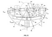
- FIG. 13is a top view of the cassette shown in FIG. 4 illustrating various feature of a ramp according to embodiments of the present invention that is configured to reduce pressure fluctuations at an input into a volumetric pump.
- FIG. 14is a block diagram of a method according to an embodiment of the present invention.
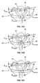
- FIGS. 15A-15Care diagrams illustrating a method of operation of a pump according to embodiments of the invention.
- the present inventionis generally directed to systems utilizing volumetric pumps configured to reduce or eliminate pressure fluctuations at the pump entrance.
- Embodiments of the present inventionmay find particular use in eye treatment systems where pressure fluctuations at the pump entrance can be propagated upstream to eye, potentially resulting in unwanted damages. Without wishing to limit the scope thereof, embodiments of the present invention will be discussed with regard to a system for treating an eye of a patient. It will be appreciated that embodiments of the invention may also be applied to other systems, including other surgical system for use in performing procedures on other parts of the body of a subject.
- a surgical system 20generally comprises an eye treatment probe or handpiece 22 that is coupled to a console 24 by a cassette 26 configured to supply irrigation and aspiration functions to the handpiece 22 .
- Handpiece 22generally includes a handle or gripping portion for manually manipulating and supporting an insertable probe tip.
- the probe tipincludes a distal end that is insertable into an eye E of a patient P, with one or more lumens in the probe tip allowing irrigation fluid to flow into the eye E.
- Aspiration fluidmay also be withdrawn through a lumen of the probe tip, with the console 24 and/or the cassette 26 generally including a vacuum aspiration source, a positive displacement or volumetric aspiration pump, or both.
- Flexible conduits 28 of the cassette 26help avoid direct contact between irrigation and aspiration fluids flowing to or from the eye and the components of console 24 .
- an electrical conductor and/or pneumatic linemay also be provided between the console 24 and the handpiece 22 .
- an electrical linemay be included to provide power from the console 24 to drive a piezoelectric device located in the handpiece 22 . This piezoelectric device helps to fragment the tissue of the lens, which can then be drawn into a port of the tip by aspiration flow.
- the handpiece 22is configured to remove vitreous material in the posterior chamber of the eye E, for example, by including an electrically or pneumatically driven cutter blade.
- a controller 30 in the console 24is generally included to control the volume of material removed by the aspiration flow, regulate irrigation flow through handpiece 22 (or a separate probe structure), manage electrical and/or pneumatic drivers connected to the handpiece 22 , and/or receive one or more input signals from sensors for monitoring the state of the system 20 during a surgical procedure.
- the controller 30may include an embedded micro-controller and/or many of the components typically found a personal computer, such as a micro-processor, data bus, memory chips, input devices, and/or output drivers.
- the controller 30may also include a user interface 31 and/or a foot pedal input device (not shown), and the like.
- Controller 30may generally include hardware, firmware, and/or software capabilities, with the software and/or firmware typically comprising machine readable code or programming instructions for implementing one, some, or all of the methods described herein.
- the codemay be embodied by a tangible media such as a memory, a magnetic recording media, an optical recording media, or the like.
- Controller 30may have (or be coupled to) a recording media reader, or the code may be transmitted to controller 30 by a network connection such as an internet, an intranet, an EthernetTM, a wireless network, or the like.
- controller 30may include stored data or correlations for implementing the methods described herein, and may generate and/or store data that records parameters corresponding to the treatment of one or more patients.
- Many components of console 24may be found in or modified from known commercial phacoemulsification systems from Advanced Medical Optics Inc. of Santa Ana, Calif.; Alcon Manufacturing, Ltd. of Fort Worth, Tex.; Bausch and Lomb of Rochester, N.Y.; and other suppliers.
- FIG. 2is a schematic representation of a cassette 26 a according to an embodiment of the invention that is disposed within a cassette frame, housing, or body 32 and having elements that interface with the console 24 , for example, to couple the console 24 to the handpiece 22 .
- An irrigation bottle, container, or source 34may be used to provide irrigation fluid pressure, for example, by relying at least in part on a gravity pressure head that varies with a height of the irrigation source 34 or the like.
- An irrigation on/off pinch valve 36may include a short segment of a resilient flexible conduit 36 a within the cassette 26 a , which can be engaged and actuated by an actuator of the console 24 .
- a surface of the cassette body 32may be disposed opposite the actuator to facilitate closure of the conduit segment.
- irrigation networkgenerally defines an irrigation fluid conduit path or line 37 between irrigation source 34 and an irrigation port on the insertable probe tip of handpiece 22 .
- irrigation fluid from the irrigation source 34is additionally or alternatively provided to a separate handpiece (not shown) that is different from the handpiece 22 .
- Aspiration of fluid and other matter from the eye E through an aspiration line 38may be provided, in conjunction with the cassette 26 a , by either a volumetric or peristaltic pump 40 and/or a holding tank 44 to which a vacuum is applied via a vacuum source 48 .
- the vacuum source 48may be directly coupled to the aspiration line 38 .
- the vacuum source 48may comprise a Venturi pump and/or a rotary vane pump; however, other types of pumps or other vacuum sources (e.g., a vacuum line) may be used in order to produce a desired vacuum level in the holding tank 44 .
- a hybrid pumpsuch as the Concentrix pump by Bausch & Lomb, may be provided that may incorporate capabilities of both a vacuum pump and a flow pump.
- the peristaltic pump 40is formed by engagement of the cassette 26 a with a pump head 50 , which may be part of the console 24 .
- the pump head 50includes one or more rotating projections, fingers, or rollers 52 disposed about an axis and near a ramp 54 that may be molded or attached to the cassette body 32 .
- the pump head 50may be formed within or attached to the cassette body 32 .
- Fluid transfer by the peristaltic pump 40is produced as a resilient channel 56 , in fluid communication with the aspiration line 38 , is engaged by or squeezed between the ramp 54 and one or more of the projections 52 .
- the resilient channel 56may be a portion of a tube made of a polymer or other suitable material.
- the resilient channel 56may be part of a molded channel and/or a gland that is squeezed or compressed during operation of the peristaltic pump 40 .
- the ramp 54may be configured according to embodiments of the invention to reduce pressure variations within the aspiration line 38 that can be produced when the resilient channel 56 is initially engaged by the protrusions 52 . Fluid aspirated through the handpiece 22 may be deposited in the holding tank 44 , regardless of whether the peristaltic pump 40 or the vacuum source 48 is used.
- a second volumetric or peristaltic pump 60may be configured as a drain pump that intermittently transfers fluid from the holding tank 44 to a waste bag 62 .
- a selector valve 64may be used to select the source of aspiration for the handpiece 22 .
- the peristaltic pump 40may be used for producing aspiration flow from the handpiece 22 , generally independent of the pressure in the holding tank 44 .
- the vacuum source 48may be used in conjunction with the holding tank 44 to produce aspiration flow by opening the valve 64 and halting rotation of the peristaltic pump 40 .
- peristaltic pump 40is not being operated, at least one of the protrusions 52 pinches off the arcuate resilient channel 56 , thus preventing aspiration flow therethrough. Material is instead drawn into an aspiration port of handpiece 12 via the vacuum source 48 through the open valve 64 .
- the aspiration portdraws fluid therein based on the pressure differential between holding tank 44 and the chamber of the eye E in which the fluid port is disposed.
- a pressure sensing device or vacuum sensor 66may be used to determine or estimate an aspiration pressure, flow rate, line deformation, or the like, and to adjust operation of the peristaltic pump 40 and/or the vacuum source 48 so as to maintain a predetermined flow rate or pressure level at the vacuum sensor 66 or elsewhere within the system.
- the vacuum sensor 66is coupled to the console 24 to provide a pressure sensing mechanism providing an output that is used by the controller 30 to control one or more aspects of the system 20 .
- a cassette 26 bcomprises only the single peristaltic pump 40 , which is available for providing aspiration through the handpiece 22 .
- the cassettes 26 a and 26 bmay use a common cassette body 32 and various other components used in both configurations (e.g., the vacuum sensor 66 ).
- the valve 64may be used provide venting or reflux to the handpiece 22 .
- an equalization pressureis provided between the irrigation and aspiration lines 37 , 38 , for example during an occlusion of the aspiration tip of the handpiece 22 .
- FIGS. 4-6illustrate perspective and front views of a portion of the system 20 that is schematically illustrated in FIG. 2 , illustrating various elements of the console 22 and the cassette 26 a (or alternatively cassette 26 b ). For clarity, the handpiece 22 and the irrigation source 34 are not illustrated in the FIGS. 4-6 .
- the cassette 26is shown separated from the console 24 , while in FIG. 6 the cassette 26 is shown engaged with the console 24 so as to couple a handpiece or eye treatment probe with the console 24 .
- FIGS. 4-6illustrate various components of the console 24 and the cassette 26 b , including the pump head 50 with the plurality of projections 52 thereof.
- the projections 52may be attached at one of their ends to a drive plate 50 a and configured to rotate about an axis A1.
- the projectionsmay also be commonly joined at their opposite ends to an attachment plate 50 b , for example, to increase rigidity.
- the console 24may also include a second pump head 70 that can be used in the drain peristaltic pump 60 .
- the second pump head 70comprises projections, fingers, or rollers 72 that are configured to rotate about an axis A2.
- the axes A1 and A2are collinear; however, other relationships between the axes A1 and A2 are possible (e.g., the axes may be parallel to one another, orthogonal to one another, or coplanar).
- FIG. 7is an exploded view of the cassette 26 a .
- Various components and fluid lines disposed within the cassette body 32are clearly visible.
- the resilient channel 56is seen in an uncompressed state and arcuately shaped to generally fit along the ramp 54 that is formed in the cassette frame 32 .
- the fluid lines in the illustrated embodimentare in the form of flexible tubing; however, all or portions of the fluid lines of the cassette 26 a (or 26 b ) may be replaced other types of channeling.
- all or portions of the fluidic lines of the cassette 26 a (or 26 b )may be at least partially replaced by channels appropriately formed in a cassette frame.
- the channelsmay be formed by the combination of the cassette frame 32 and a resilient cover, for example, as disclosed in U.S. Pat. No. 6,962,488.
- the cassette 26 a(or 26 b ) comprises first and second collars 73 a , 73 b that are disposed along the resilient channel 56 .
- the collars 73 a , 73 bare molded or otherwise attached to the resilient channel 56 so as to prevent slippage therebetween.
- the collars 73 a , 73 bmay be separated by a predetermined distance L that is selected to provide efficient pump performance when the resilient channel 56 is mounted to the cassette, for example, by insertion into receivers 74 a , 74 b , respectively.
- the receivers 74 a , 74 bare located on bosses between which the ramp 54 is disposed.
- the collars 73 a , 73 bmay be keyed to provide a preferred orientation of the collars within the receivers 74 a , 74 b .
- the keyed collars 73 a , 73 bmay be configured so that they can be mounted only in one orientation within the receivers 74 a , 74 b or may simply be shaped so that the correct orientation is evident upon visual inspection.
- FIGS. 9 and 10show cutaway top views of the console 24 and the cassette 26 particularly illustrating the relationship between the projections 52 of the head 50 and the ramp 54 formed in the cassette frame 32 .
- the resilient channel 56is not shown in FIG. 9 .
- the resilient channel 56is shown compressed between the ramp 54 and two of the projections 52 of the pump head 50 .
- the ramp 54is configured to at least partially enclose at least some of the projections 52 when the cassette 26 is engaged with the console 24 .
- the aspiration pump 40is formed by the engagement of the cassette 26 with the console 24 .
- the projections 52rotate about the axis A1
- fluid and other materialis entrapped within a volume 76 of the resilient channel 56 and transferred from an inlet portion of the peristaltic pump 40 to an exit portion thereof.
- the resilient channel 56is fluidly connected to the aspiration line 38
- the materialis transferred from the eye E and through the peristaltic pump 40 as the resilient channel 56 is repeatedly engaged by or squeezed between the ramp 54 and the plurality of projections 52 .
- the profile of the ramp 54may be configured mitigate or substantially eliminate large and/or rapid variations in the pressure of the aspiration line 38 as each of the projections 52 initially engages and subsequently squeezes the resilient channel 56 .
- FIGS. 11 and 12illustrate the cassette 26 with associated components of the system 20 , including but not limited to, irrigation inlet and outlet lines 37 a , 37 b , aspiration line 38 , waste bag 62 , holding tank 44 , and vacuum sensor 66 .
- the same cassette body 32may be configured for use with only the aspiration peristaltic pump 40 , as discussed in relation to the system schematically illustrated in FIG. 3 .
- the irrigation and aspiration lines 37 b , 38are configured to be coupled to the handpiece 22 , allowing the cassette 26 to provide at least irrigation fluid to, and aspiration of fluid from, the eye E.
- the system 20 handpiecefurther comprises means for emulsification of the natural lens of the eye E.
- an ultrasonically driven piezoelectric crystalmay be used to provide this function; however, other means are consistent with embodiments of the present invention, for example, a high energy laser beam.
- the handpiece 22is configured to cut and remove vitreous material in the posterior chamber of the eye E, for example, by including an electrically or pneumatically driven cutter blade.
- the ramp 54is configured to have an arcuate form that can reduce or substantially eliminate rapid and/or large pressure fluctuations in the aspiration line 38 and the eye E caused by the peristaltic pump 40 .
- the dotted circle Pillustrates an approximate path of the distal most portions of projections 52 (i.e., the point or line on each projection 52 that is closest to ramp 54 as the pump head 50 rotates).
- the ramp 54comprises a central portion 80 generally configured such that the resilient channel 56 is completely sealed or substantially sealed as the projections 52 rotate or move along the central portion 80 of the ramp 54 .
- the shape of the central portion 80may be characterized by a base curvature C central that is generally constant, although the shape of the central portion 80 may vary in accordance with particular design requirements or constraints.
- the ramp 54also comprises an entrance portion 82 having an arcuate extent over which one of the projections 52 closes the resilient channel 56 as the projections 52 move by the ramp 54 .
- the entrance portion 82may be characterized by a base curvature C entrance that is different from the base curvature C central , preferably less than the curvature C central .
- the decreased curvature C entrance of the entrance portion 82may be configured to reduce the rate at which the resilient channel 56 is compressed, thus reducing or eliminating pressure fluctuations in the aspiration line 38 and eye E.
- the transition between entrance portion 82 and the central portion 80is made generally smooth, for example, by configuring the entrance and central portions 82 , 80 to be tangent at a connection point or line therebetween.
- the shape of the entrance portion 82may have a constant curvature; however, as discussed in greater detail below, a more complex shape may advantageously further reduce pressure fluctuations at the entrance to the peristaltic pump 40 .
- the ramp 54further comprises an exit portion 84 having an arcuate extent and characterized by a base curvature C exit that is different from the base curvature C central .
- the shape of the exit portion 84may have a constant curvature, although the shape may vary in accordance with particular design requirements or constraints.
- the extent of the entrance portion 82is unequal to the extent of the exit portion 84 .
- the entrance portion 82has a greater extent than that of the exit portion 84 , for example, to provide a greater time and distance over which the resilient channel 56 is gradually squeezed or compressed. By increasing the extent of the entrance portion, the rate at which resilient channel 56 is compressed may be decreased, thus allowing the pressure fluctuations in the aspiration line 38 to be reduced.
- the smaller extent of the exit portion 84produce a relatively large or rapid pressure increase at the exit of the pump 40 and the resilient channel 56 . In general, this will not cause problems, since the exit of the resilient channel is isolated from the aspiration line 38 and the eye E. In some instance, however, the entrance portion 82 may actually have a smaller extent than that of the exit portion 84 , depending upon the choices of a particular designer.
- the extent of the portions 80 , 82 , 84may have generally arcuate extents. These arcuate extents may be approximately centered about center of the dotted circle P, although it will be appreciated that portions of the portions 80 , 82 , 84 , particularly of the entrance portion 82 , may have very large radii of curvature (even infinite) that are centered at great distances from the center of the dotted circle P.
- the pump 40may be linear or substantially linear in its operation, in which case the extent of one or more of the portions 80 , 82 , 84 may be partially or substantially linear in nature or have very large radii of curvature.
- exit portion 84 of the ramp 54has an arcuate or angular extent ⁇ exit .
- the exit portion 84is substantially linear, in which case the extent is more appropriately expressed as an linear distance, rather than an angular extent.
- the central portion 80 of the ramp 54has an arcuate or angular extent ⁇ central that preferably is much greater than ⁇ exit .
- the angular extent of the central portion 80is at least 90 degrees in order that at least two of the projections 52 of the peristaltic pump 40 close the resilient channel 56 at any given time or position of the pump head 50 .
- the angular extent ⁇ centralis 100 degrees or about 100 degrees, for example, when the pump head has four projections 52 that are approximately 90 degrees apart from one another. In other embodiments, the angular extent ⁇ central is between about 90 degrees and about 120 degrees. In yet other embodiments, the angular extent ⁇ central may be less than about 90 degrees, for example, when the pump head has five, six, or more projections 52 that are approximately evenly space apart from one another. Alternatively, the angular extent ⁇ central may be greater than 120 degrees, 130 degrees, or even 140 degrees, for example, when the pump head has two or three projections 52 that are approximately evenly space apart from one another.
- the entrance portion 82 of the ramp 54has a substantially arcuate extent from line 94 to line 96 shown in FIG. 13 .
- the entrance portion 82comprises a proximal portion 100 near the entrance into the pump 40 (e.g., at or near the intersection of the ramp 54 with the line 94 ) and a distal portion 102 near the central portion 82 of the ramp 54 (e.g., disposed at or near the intersection of the ramp 54 profile with the line 96 ).
- the profile of entrance portion 82generally moves progressively further from the circle P when moving from the proximal portion 100 to the distal portion 102 .
- proximal portion 100is disposed farther away from the circle P than the distal portion 102 .
- proximal portion 100is configured such that when the projections 52 of the pump 40 initially engage the resilient channel 56 , the resilient channel 56 moves away from the circle P and/or toward the proximal portion 100 of the ramp 54 . This may advantageously reduce or eliminate the production of pressure waves or variations in the aspiration line 38 that might otherwise damage the eye E.
- the entrance portion 82 of the ramp 54may comprise adjoining first segment 110 , second segment 112 , third segment 114 , and fourth segment 116 .
- Each of the segments 110 , 112 , 114 , 116may have a curvature that is constant over most of their extents and may include relatively small transition portions between each of the segments for providing smooth transitions therebetween.
- one or more of the segments 110 , 112 , 114 , 116may comprise a non-circular profile, for example, a profile that varies slightly from a base curvature with a predetermined radius of curvature.
- the second segment 112has a curvature that is less than that of the first segment 110 .
- the second segment 112has a curvature of zero (e.g., a straight line) or nearly zero (e.g., a very large radius of curvature).
- the first and/or second segments 110 , 112may be configured to provide a predetermined location of the proximal portion 100 , so as to provide a desired interaction between the resilient channel 54 and the projections 52 upon engagement therebetween.
- the third segment 114has a relatively large curvature that is greater than that of the second segment 112 .
- the third segment 114may be configured provide a predetermined orientation of the proximal portion 100 .
- the fourth segment 116has curvature that is less than the curvature of the second segment, and is preferably straight, nearly straight, or only slightly arcuate in shape.
- the cassette housing 32comprises a front face 88 that is substantially symmetrically disposed about a central axis or perpendicular plane.
- the front face 88is substantially normal to a first axis 90
- the central portion 80is asymmetrically disposed about the first axis 90 .
- the central portion 80may be symmetrically disposed about a second axis 92 that itself is disposed at an angle ⁇ offset relative to the first axis 90 (where positive angles in FIG. 13 are in a clockwise direction from the first axis 90 ).
- the angular extent ⁇ central of the central portion 90is about 100 degrees and ⁇ offset is about 30 degrees.
- the angle ⁇ offsetis between about ⁇ 40 degrees and about +40 degrees, preferably between ⁇ 30 degrees and +30 degrees.
- ⁇ offsetis between about 0 degrees and about 50 degrees, preferably between about 20 degrees and about 40 degrees. The ranges may, of course, change depending on the particular design parameters, for example, the number of projections 52 in the head 50 of the pump 40 .
- a method 200 of operating the surgical treatment system 20comprises an operational block 210 of engaging a cassette according to embodiments of the present invention (e.g., one of the cassettes 26 , 26 a , or 26 b ) with the console 24 so as to form the pump 40 and to couple the handpiece 22 with the console 24 .
- the method 200also comprises an operational block 220 of rotating at least one projection 52 of the peristaltic pump 40 so as to engage a portion of the resilient channel 56 .
- the method 200additionally comprises an operational block 230 of compressing or closing the resilient channel 56 over an extent ⁇ entrance so as to draw in fluid and/or other material inside the resilient channel 56 .
- the method 200further comprises an operational block 240 of maintaining the resilient channel 56 in a sealed or closed condition over an extent ⁇ central .
- the method 200also comprises an operational block 250 of expanding or opening the resilient channel 56 over an extent ⁇ exit so as to allow material to be ejected from the peristaltic pump 40 , wherein the extent ⁇ entrance is greater than the extent ⁇ exit .
Landscapes
- Health & Medical Sciences (AREA)
- Engineering & Computer Science (AREA)
- Heart & Thoracic Surgery (AREA)
- Veterinary Medicine (AREA)
- Biomedical Technology (AREA)
- Life Sciences & Earth Sciences (AREA)
- Animal Behavior & Ethology (AREA)
- General Health & Medical Sciences (AREA)
- Public Health (AREA)
- Vascular Medicine (AREA)
- Hematology (AREA)
- Anesthesiology (AREA)
- Mechanical Engineering (AREA)
- General Engineering & Computer Science (AREA)
- Ophthalmology & Optometry (AREA)
- Pulmonology (AREA)
- Nuclear Medicine, Radiotherapy & Molecular Imaging (AREA)
- Surgery (AREA)
- Computer Hardware Design (AREA)
- External Artificial Organs (AREA)
- Infusion, Injection, And Reservoir Apparatuses (AREA)
Abstract
Description
Claims (11)
Priority Applications (9)
| Application Number | Priority Date | Filing Date | Title |
|---|---|---|---|
| US11/558,416US9033940B2 (en) | 2006-11-09 | 2006-11-09 | Eye treatment system with fluidics pump interface |
| EP07863983.8AEP2079931B8 (en) | 2006-11-09 | 2007-11-06 | Eye treatment system with fluidics pump interface |
| EP13153232.7AEP2596817B1 (en) | 2006-11-09 | 2007-11-06 | Eye treatment system with fluidics pump interface |
| PCT/US2007/083807WO2008060903A2 (en) | 2006-11-09 | 2007-11-06 | Eye treatment system with fluidics pump interface |
| CA2668727ACA2668727C (en) | 2006-11-09 | 2007-11-06 | Eye treatment system with fluidics pump interface |
| AU2007319509AAU2007319509B2 (en) | 2006-11-09 | 2007-11-06 | Eye treatment system with fluidics pump interface |
| CA2910143ACA2910143C (en) | 2006-11-09 | 2007-11-06 | Eye treatment system with fluidics pump interface |
| US14/703,485US9974687B2 (en) | 2006-11-09 | 2015-05-04 | Eye treatment system with fluidics pump interface |
| US15/984,272US11116661B2 (en) | 2006-11-09 | 2018-05-18 | Eye treatment system with fluidics pump interface |
Applications Claiming Priority (1)
| Application Number | Priority Date | Filing Date | Title |
|---|---|---|---|
| US11/558,416US9033940B2 (en) | 2006-11-09 | 2006-11-09 | Eye treatment system with fluidics pump interface |
Related Child Applications (1)
| Application Number | Title | Priority Date | Filing Date |
|---|---|---|---|
| US14/703,485DivisionUS9974687B2 (en) | 2006-11-09 | 2015-05-04 | Eye treatment system with fluidics pump interface |
Publications (2)
| Publication Number | Publication Date |
|---|---|
| US20080114312A1 US20080114312A1 (en) | 2008-05-15 |
| US9033940B2true US9033940B2 (en) | 2015-05-19 |
Family
ID=39370138
Family Applications (3)
| Application Number | Title | Priority Date | Filing Date |
|---|---|---|---|
| US11/558,416Active2030-05-15US9033940B2 (en) | 2006-11-09 | 2006-11-09 | Eye treatment system with fluidics pump interface |
| US14/703,485Active2027-10-27US9974687B2 (en) | 2006-11-09 | 2015-05-04 | Eye treatment system with fluidics pump interface |
| US15/984,272Active2028-12-30US11116661B2 (en) | 2006-11-09 | 2018-05-18 | Eye treatment system with fluidics pump interface |
Family Applications After (2)
| Application Number | Title | Priority Date | Filing Date |
|---|---|---|---|
| US14/703,485Active2027-10-27US9974687B2 (en) | 2006-11-09 | 2015-05-04 | Eye treatment system with fluidics pump interface |
| US15/984,272Active2028-12-30US11116661B2 (en) | 2006-11-09 | 2018-05-18 | Eye treatment system with fluidics pump interface |
Country Status (5)
| Country | Link |
|---|---|
| US (3) | US9033940B2 (en) |
| EP (2) | EP2079931B8 (en) |
| AU (1) | AU2007319509B2 (en) |
| CA (2) | CA2910143C (en) |
| WO (1) | WO2008060903A2 (en) |
Cited By (9)
| Publication number | Priority date | Publication date | Assignee | Title |
|---|---|---|---|---|
| US20150367046A1 (en)* | 2012-03-17 | 2015-12-24 | Abbott Medical Optics Inc. | Two piece ultrasonic welded fluid manifold with two shot over molded irrigation and aspiration valve and vacuum chamber diaphragm |
| US20180230987A1 (en)* | 2017-02-14 | 2018-08-16 | Surpass Industry Co., Ltd. | Tube pump and holding mechanism |
| US10219940B2 (en) | 2008-11-07 | 2019-03-05 | Johnson & Johnson Surgical Vision, Inc. | Automatically pulsing different aspiration levels to an ocular probe |
| US10238778B2 (en) | 2008-11-07 | 2019-03-26 | Johnson & Johnson Surgical Vision, Inc. | Automatically switching different aspiration levels and/or pumps to an ocular probe |
| US10265443B2 (en) | 2008-11-07 | 2019-04-23 | Johnson & Johnson Surgical Vision, Inc. | Surgical cassette apparatus |
| US10342701B2 (en) | 2007-08-13 | 2019-07-09 | Johnson & Johnson Surgical Vision, Inc. | Systems and methods for phacoemulsification with vacuum based pumps |
| US10959881B2 (en) | 2006-11-09 | 2021-03-30 | Johnson & Johnson Surgical Vision, Inc. | Fluidics cassette for ocular surgical system |
| US11337855B2 (en) | 2006-11-09 | 2022-05-24 | Johnson & Johnson Surgical Vision, Inc. | Holding tank devices, systems, and methods for surgical fluidics cassette |
| US20220362452A1 (en)* | 2021-05-12 | 2022-11-17 | Johnson & Johnson Surgical Vision, Inc. | Disposable pump cartridge |
Families Citing this family (35)
| Publication number | Priority date | Publication date | Assignee | Title |
|---|---|---|---|---|
| US20090043365A1 (en) | 2005-07-18 | 2009-02-12 | Kolis Scientific, Inc. | Methods, apparatuses, and systems for reducing intraocular pressure as a means of preventing or treating open-angle glaucoma |
| US8380126B1 (en) | 2005-10-13 | 2013-02-19 | Abbott Medical Optics Inc. | Reliable communications for wireless devices |
| US8565839B2 (en) | 2005-10-13 | 2013-10-22 | Abbott Medical Optics Inc. | Power management for wireless devices |
| US9295765B2 (en)* | 2006-11-09 | 2016-03-29 | Abbott Medical Optics Inc. | Surgical fluidics cassette supporting multiple pumps |
| US8491528B2 (en) | 2006-11-09 | 2013-07-23 | Abbott Medical Optics Inc. | Critical alignment of fluidics cassettes |
| US9522221B2 (en) | 2006-11-09 | 2016-12-20 | Abbott Medical Optics Inc. | Fluidics cassette for ocular surgical system |
| US20110088151A1 (en)* | 2007-04-17 | 2011-04-21 | Semra Peksoz | Firefighter's turnout coat with seamless collar |
| US10485699B2 (en) | 2007-05-24 | 2019-11-26 | Johnson & Johnson Surgical Vision, Inc. | Systems and methods for transverse phacoemulsification |
| US10596032B2 (en) | 2007-05-24 | 2020-03-24 | Johnson & Johnson Surgical Vision, Inc. | System and method for controlling a transverse phacoemulsification system with a footpedal |
| US10363166B2 (en) | 2007-05-24 | 2019-07-30 | Johnson & Johnson Surgical Vision, Inc. | System and method for controlling a transverse phacoemulsification system using sensed data |
| US8162633B2 (en)* | 2007-08-02 | 2012-04-24 | Abbott Medical Optics Inc. | Volumetric fluidics pump with translating shaft path |
| US8272857B2 (en) | 2008-02-22 | 2012-09-25 | Medtronic Xomed, Inc. | Method and system for loading of tubing into a pumping device |
| EP2140890A1 (en)* | 2008-07-03 | 2010-01-06 | Bien-Air Holding SA | Peristaltic pump and irrigation line |
| EP3156012B1 (en) | 2008-11-07 | 2021-10-20 | Johnson & Johnson Surgical Vision, Inc. | Adjustable foot pedal control for ophthalmic surgery |
| EP2341878B1 (en) | 2008-11-07 | 2017-06-21 | Abbott Medical Optics Inc. | Semi-automatic device calibraton |
| US8469050B2 (en)* | 2008-11-07 | 2013-06-25 | Abbott Medical Optics Inc. | Capacitive fluid level sensing |
| EP2373265B1 (en) | 2008-11-07 | 2016-03-09 | Abbott Medical Optics Inc. | Controlling of multiple pumps |
| US9795507B2 (en) | 2008-11-07 | 2017-10-24 | Abbott Medical Optics Inc. | Multifunction foot pedal |
| US10349925B2 (en)* | 2008-11-07 | 2019-07-16 | Johnson & Johnson Surgical Vision, Inc. | Method for programming foot pedal settings and controlling performance through foot pedal variation |
| US9492317B2 (en) | 2009-03-31 | 2016-11-15 | Abbott Medical Optics Inc. | Cassette capture mechanism |
| CN102413849B (en) | 2009-05-06 | 2015-02-11 | 爱尔康研究有限公司 | Multiple segmented peristaltic pump and cassette |
| US8876757B2 (en)* | 2009-11-12 | 2014-11-04 | Abbott Medical Optics Inc. | Fluid level detection system |
| US20110137231A1 (en) | 2009-12-08 | 2011-06-09 | Alcon Research, Ltd. | Phacoemulsification Hand Piece With Integrated Aspiration Pump |
| DE202011104787U1 (en)* | 2011-08-19 | 2012-11-27 | FRITZ RUCK Ophthalmologische Systeme GmbH | Ophthalmic cassette |
| DE102011114468B4 (en)* | 2011-09-28 | 2016-08-11 | Carl Zeiss Meditec Ag | Ophthalmosurgical cassette |
| CA2882220A1 (en) | 2012-12-11 | 2014-06-19 | Alcon Research Ltd. | Phacoemulsification hand piece with integrated aspiration and irrigation pump |
| ES2676718T3 (en) | 2012-12-21 | 2018-07-24 | Alcon Research, Ltd. | Cassette clamping system |
| US9962288B2 (en) | 2013-03-07 | 2018-05-08 | Novartis Ag | Active acoustic streaming in hand piece for occlusion surge mitigation |
| US9693896B2 (en) | 2013-03-15 | 2017-07-04 | Novartis Ag | Systems and methods for ocular surgery |
| US9545337B2 (en) | 2013-03-15 | 2017-01-17 | Novartis Ag | Acoustic streaming glaucoma drainage device |
| US9750638B2 (en) | 2013-03-15 | 2017-09-05 | Novartis Ag | Systems and methods for ocular surgery |
| US9915274B2 (en) | 2013-03-15 | 2018-03-13 | Novartis Ag | Acoustic pumps and systems |
| US9126219B2 (en) | 2013-03-15 | 2015-09-08 | Alcon Research, Ltd. | Acoustic streaming fluid ejector |
| US10369268B2 (en) | 2014-09-19 | 2019-08-06 | Coloplast A/S | Anal irrigation system |
| GB2616273A (en)* | 2022-03-01 | 2023-09-06 | Aliva AS | Liquid distribution system |
Citations (23)
| Publication number | Priority date | Publication date | Assignee | Title |
|---|---|---|---|---|
| US4187057A (en)* | 1978-01-11 | 1980-02-05 | Stewart-Naumann Laboratories, Inc. | Peristaltic infusion pump and disposable cassette for use therewith |
| US4627833A (en)* | 1982-06-01 | 1986-12-09 | Site Microsurgical Systems, Inc. | Microsurgical system cassette assembly |
| US4758238A (en)* | 1985-09-25 | 1988-07-19 | Alcon Laboratories, Inc. | Fast response tubeless vacuum aspiration collection cassette |
| US4920336A (en) | 1988-11-22 | 1990-04-24 | Fisher Scientific Company | Method and apparatus for monitoring the level of the contents in a container |
| US5125891A (en) | 1987-04-27 | 1992-06-30 | Site Microsurgical Systems, Inc. | Disposable vacuum/peristaltic pump cassette system |
| US5195960A (en) | 1987-04-27 | 1993-03-23 | Site Microsurgical Systems, Inc. | Disposable vacuum/peristaltic pump cassette system |
| US5230614A (en) | 1992-06-03 | 1993-07-27 | Allergan, Inc. | Reduced pulsation tapered ramp pump head |
| WO1993017729A1 (en) | 1992-03-03 | 1993-09-16 | Alcon Surgical, Inc. | System and apparatus for controlling fluid flow from a surgical handpiece |
| US5454783A (en) | 1992-11-06 | 1995-10-03 | Grieshaber & Co Ag Schaffhausen | Apparatus for microsurgical operations on the eye of a living being |
| US5470211A (en) | 1993-08-12 | 1995-11-28 | Stockert Instrumente Gmbh | Roller pump |
| US5499969A (en)* | 1992-02-05 | 1996-03-19 | Nestle S.A. | Microsurgical cassette |
| US5549461A (en) | 1995-07-21 | 1996-08-27 | Newland; George | Peristaltic pump attachment for slurry mixers |
| US5676530A (en) | 1996-01-24 | 1997-10-14 | Alcon Laboratories, Inc. | Surgical cassette latching mechanism |
| US5693020A (en) | 1994-07-28 | 1997-12-02 | Loctite Europa E.E.I.G. (E.W.I.V.) | Hose pump for the exact dosing of small quantities of liquids |
| US5747824A (en) | 1995-12-01 | 1998-05-05 | Alcon Laboratories, Inc. | Apparatus and method for sensing fluid level |
| WO2000070225A1 (en) | 1999-05-12 | 2000-11-23 | G John Andersen | Peristaltic fluid pump |
| US20030108429A1 (en) | 2001-11-09 | 2003-06-12 | Giampiero Angelini | Infusion-suction (I/S) cassette provided with suction system having both a peristaltic or volumetric pump and a pressure sensitive (or Venturi) pump |
| US20040037724A1 (en) | 2000-12-12 | 2004-02-26 | Christian Haser | Peristaltic hose pump |
| US20050069419A1 (en) | 2003-09-29 | 2005-03-31 | Cull Laurence J. | Peristaltic pump with air venting via the movement of a pump head or a backing plate during surgery |
| US6902542B2 (en)* | 2002-05-28 | 2005-06-07 | Alcon, Inc. | Identification system for a surgical cassette |
| US6962488B2 (en) | 1999-11-10 | 2005-11-08 | Alcon, Inc. | Surgical cassette having an aspiration pressure sensor |
| US7070578B2 (en) | 2002-04-25 | 2006-07-04 | Alcon, Inc. | Surgical cassette latching mechanism |
| US7214038B2 (en)* | 2002-09-23 | 2007-05-08 | Ismatec Sa | Hose cartridge for a peristaltic pump |
Family Cites Families (12)
| Publication number | Priority date | Publication date | Assignee | Title |
|---|---|---|---|---|
| DE2921066A1 (en) | 1979-05-23 | 1980-11-27 | Siemens Ag | ROLL PUMP |
| DE4135609A1 (en) | 1991-10-29 | 1993-05-06 | Fresenius Ag, 6380 Bad Homburg, De | Rolling-action peristaltic pump - has bearing-bed asymmetrical in relation to inlet and outlet axes, including rotor axis |
| US5267956A (en) | 1992-02-05 | 1993-12-07 | Alcon Surgical, Inc. | Surgical cassette |
| ATE161948T1 (en) | 1992-06-03 | 1998-01-15 | Allergan Inc | PRESSURE TRANSDUCER - INTERFACE |
| WO1993024082A1 (en)* | 1992-06-03 | 1993-12-09 | Allergan, Inc. | Tubing management system |
| US5324180A (en)* | 1992-09-04 | 1994-06-28 | Allergan, Inc. | Surgical instrument with drawer loading cassette system |
| GB2285837B (en) | 1994-01-24 | 1998-05-13 | Varian Australia | Peristaltic pump |
| US6099272A (en) | 1997-09-18 | 2000-08-08 | Fsi International | Peristaltic pump with flow control |
| US6155975A (en) | 1998-11-06 | 2000-12-05 | Urich; Alex | Phacoemulsification apparatus with personal computer |
| US6592653B2 (en)* | 2001-11-12 | 2003-07-15 | Advanced Technology Materials, Inc. | Fluid storage and delivery system utilizing low heels carbon sorbent medium |
| US20050245888A1 (en) | 2004-04-29 | 2005-11-03 | Cull Laurence J | Combined peristaltic and vacuum aspiration cassette |
| US7347751B2 (en)* | 2004-09-30 | 2008-03-25 | Cardiac Pacemakers, Inc. | Cardiac lead implantation system |
- 2006
- 2006-11-09USUS11/558,416patent/US9033940B2/enactiveActive
- 2007
- 2007-11-06EPEP07863983.8Apatent/EP2079931B8/enactiveActive
- 2007-11-06CACA2910143Apatent/CA2910143C/ennot_activeExpired - Fee Related
- 2007-11-06AUAU2007319509Apatent/AU2007319509B2/ennot_activeCeased
- 2007-11-06EPEP13153232.7Apatent/EP2596817B1/ennot_activeRevoked
- 2007-11-06WOPCT/US2007/083807patent/WO2008060903A2/enactiveApplication Filing
- 2007-11-06CACA2668727Apatent/CA2668727C/ennot_activeExpired - Fee Related
- 2015
- 2015-05-04USUS14/703,485patent/US9974687B2/enactiveActive
- 2018
- 2018-05-18USUS15/984,272patent/US11116661B2/enactiveActive
Patent Citations (23)
| Publication number | Priority date | Publication date | Assignee | Title |
|---|---|---|---|---|
| US4187057A (en)* | 1978-01-11 | 1980-02-05 | Stewart-Naumann Laboratories, Inc. | Peristaltic infusion pump and disposable cassette for use therewith |
| US4627833A (en)* | 1982-06-01 | 1986-12-09 | Site Microsurgical Systems, Inc. | Microsurgical system cassette assembly |
| US4758238A (en)* | 1985-09-25 | 1988-07-19 | Alcon Laboratories, Inc. | Fast response tubeless vacuum aspiration collection cassette |
| US5125891A (en) | 1987-04-27 | 1992-06-30 | Site Microsurgical Systems, Inc. | Disposable vacuum/peristaltic pump cassette system |
| US5195960A (en) | 1987-04-27 | 1993-03-23 | Site Microsurgical Systems, Inc. | Disposable vacuum/peristaltic pump cassette system |
| US4920336A (en) | 1988-11-22 | 1990-04-24 | Fisher Scientific Company | Method and apparatus for monitoring the level of the contents in a container |
| US5499969A (en)* | 1992-02-05 | 1996-03-19 | Nestle S.A. | Microsurgical cassette |
| WO1993017729A1 (en) | 1992-03-03 | 1993-09-16 | Alcon Surgical, Inc. | System and apparatus for controlling fluid flow from a surgical handpiece |
| US5230614A (en) | 1992-06-03 | 1993-07-27 | Allergan, Inc. | Reduced pulsation tapered ramp pump head |
| US5454783A (en) | 1992-11-06 | 1995-10-03 | Grieshaber & Co Ag Schaffhausen | Apparatus for microsurgical operations on the eye of a living being |
| US5470211A (en) | 1993-08-12 | 1995-11-28 | Stockert Instrumente Gmbh | Roller pump |
| US5693020A (en) | 1994-07-28 | 1997-12-02 | Loctite Europa E.E.I.G. (E.W.I.V.) | Hose pump for the exact dosing of small quantities of liquids |
| US5549461A (en) | 1995-07-21 | 1996-08-27 | Newland; George | Peristaltic pump attachment for slurry mixers |
| US5747824A (en) | 1995-12-01 | 1998-05-05 | Alcon Laboratories, Inc. | Apparatus and method for sensing fluid level |
| US5676530A (en) | 1996-01-24 | 1997-10-14 | Alcon Laboratories, Inc. | Surgical cassette latching mechanism |
| WO2000070225A1 (en) | 1999-05-12 | 2000-11-23 | G John Andersen | Peristaltic fluid pump |
| US6962488B2 (en) | 1999-11-10 | 2005-11-08 | Alcon, Inc. | Surgical cassette having an aspiration pressure sensor |
| US20040037724A1 (en) | 2000-12-12 | 2004-02-26 | Christian Haser | Peristaltic hose pump |
| US20030108429A1 (en) | 2001-11-09 | 2003-06-12 | Giampiero Angelini | Infusion-suction (I/S) cassette provided with suction system having both a peristaltic or volumetric pump and a pressure sensitive (or Venturi) pump |
| US7070578B2 (en) | 2002-04-25 | 2006-07-04 | Alcon, Inc. | Surgical cassette latching mechanism |
| US6902542B2 (en)* | 2002-05-28 | 2005-06-07 | Alcon, Inc. | Identification system for a surgical cassette |
| US7214038B2 (en)* | 2002-09-23 | 2007-05-08 | Ismatec Sa | Hose cartridge for a peristaltic pump |
| US20050069419A1 (en) | 2003-09-29 | 2005-03-31 | Cull Laurence J. | Peristaltic pump with air venting via the movement of a pump head or a backing plate during surgery |
Cited By (30)
| Publication number | Priority date | Publication date | Assignee | Title |
|---|---|---|---|---|
| US11918729B2 (en) | 2006-11-09 | 2024-03-05 | Johnson & Johnson Surgical Vision, Inc. | Fluidics cassette for ocular surgical system |
| US11337855B2 (en) | 2006-11-09 | 2022-05-24 | Johnson & Johnson Surgical Vision, Inc. | Holding tank devices, systems, and methods for surgical fluidics cassette |
| US11065153B2 (en) | 2006-11-09 | 2021-07-20 | Johnson & Johnson Surgical Vision, Inc. | Fluidics cassette for ocular surgical system |
| US11058577B2 (en) | 2006-11-09 | 2021-07-13 | Johnson & Johnson Surgical Vision, Inc. | Fluidics cassette for ocular surgical system |
| US10959881B2 (en) | 2006-11-09 | 2021-03-30 | Johnson & Johnson Surgical Vision, Inc. | Fluidics cassette for ocular surgical system |
| US10342701B2 (en) | 2007-08-13 | 2019-07-09 | Johnson & Johnson Surgical Vision, Inc. | Systems and methods for phacoemulsification with vacuum based pumps |
| US10905588B2 (en) | 2008-11-07 | 2021-02-02 | Johnson & Johnson Surgical Vision, Inc. | Automatically pulsing different aspiration levels to an ocular probe |
| US10219940B2 (en) | 2008-11-07 | 2019-03-05 | Johnson & Johnson Surgical Vision, Inc. | Automatically pulsing different aspiration levels to an ocular probe |
| US10478534B2 (en) | 2008-11-07 | 2019-11-19 | Johnson & Johnson Surgical Vision, Inc. | Automatically switching different aspiration levels and/or pumps to an ocular probe |
| US10668192B2 (en) | 2008-11-07 | 2020-06-02 | Johnson & Johnson Surgical Vision, Inc. | Automatically switching different aspiration levels and/or pumps to an ocular probe |
| US11369728B2 (en) | 2008-11-07 | 2022-06-28 | Johnson & Johnson Surgical Vision, Inc. | Automatically switching different aspiration levels and/or pumps to an ocular probe |
| US10813790B2 (en) | 2008-11-07 | 2020-10-27 | Johnson & Johnson Surgical Vision, Inc. | Automatically pulsing different aspiration levels to an ocular probe |
| US10265443B2 (en) | 2008-11-07 | 2019-04-23 | Johnson & Johnson Surgical Vision, Inc. | Surgical cassette apparatus |
| US11369729B2 (en) | 2008-11-07 | 2022-06-28 | Johnson & Johnson Surgical Vision, Inc. | Automatically switching different aspiration levels and/or pumps to an ocular probe |
| US11364145B2 (en) | 2008-11-07 | 2022-06-21 | Johnson & Johnson Surgical Vision, Inc. | Automatically pulsing different aspiration levels to an ocular probe |
| US10251983B2 (en) | 2008-11-07 | 2019-04-09 | Johnson & Johnson Surgical Vision, Inc. | Automatically switching different aspiration levels and/or pumps to an ocular probe |
| US11266526B2 (en) | 2008-11-07 | 2022-03-08 | Johnson & Johnson Surgical Vision, Inc. | Automatically pulsing different aspiration levels to an ocular probe |
| US10993839B2 (en) | 2008-11-07 | 2021-05-04 | Johnson & Johnson Surgical Vision, Inc. | Automatically pulsing different aspiration levels to an ocular probe |
| US10238778B2 (en) | 2008-11-07 | 2019-03-26 | Johnson & Johnson Surgical Vision, Inc. | Automatically switching different aspiration levels and/or pumps to an ocular probe |
| US10857029B2 (en) | 2012-03-17 | 2020-12-08 | Johnson & Johnson Surgical Vision, Inc. | Valve system of surgical cassette manifold, system, and methods thereof |
| US11154422B2 (en) | 2012-03-17 | 2021-10-26 | Johnson & Johnson Surgical Vision, Inc. | Surgical cassette manifold, system, and methods thereof |
| US10980668B2 (en) | 2012-03-17 | 2021-04-20 | Johnson & Johnson Surgical Vision, Inc. | Surgical cassette |
| US10219938B2 (en) | 2012-03-17 | 2019-03-05 | Johnson & Johnson Surgical Vision, Inc. | Surgical cassette manifold, system, and methods thereof |
| US20150367046A1 (en)* | 2012-03-17 | 2015-12-24 | Abbott Medical Optics Inc. | Two piece ultrasonic welded fluid manifold with two shot over molded irrigation and aspiration valve and vacuum chamber diaphragm |
| US10888456B2 (en) | 2012-03-17 | 2021-01-12 | Johnson & Johnson Surgical Vision, Inc. | Surgical cassette |
| US11872159B2 (en) | 2012-03-17 | 2024-01-16 | Johnson & Johnson Surgical Vision, Inc. | Pre-alignment surgical cassette interface |
| US10746168B2 (en)* | 2017-02-14 | 2020-08-18 | Surpass Industry Co., Ltd. | Tube pump and holding mechanism |
| US20180230987A1 (en)* | 2017-02-14 | 2018-08-16 | Surpass Industry Co., Ltd. | Tube pump and holding mechanism |
| US20220362452A1 (en)* | 2021-05-12 | 2022-11-17 | Johnson & Johnson Surgical Vision, Inc. | Disposable pump cartridge |
| US12129848B2 (en)* | 2021-05-12 | 2024-10-29 | Johnson & Johnson Surgical Vision, Inc. | Disposable pump cartridge |
Also Published As
| Publication number | Publication date |
|---|---|
| CA2910143A1 (en) | 2008-05-22 |
| US20080114312A1 (en) | 2008-05-15 |
| US20150230977A1 (en) | 2015-08-20 |
| AU2007319509B2 (en) | 2013-10-03 |
| EP2596817B1 (en) | 2022-04-20 |
| US20180263812A1 (en) | 2018-09-20 |
| EP2079931A2 (en) | 2009-07-22 |
| EP2596817A2 (en) | 2013-05-29 |
| US9974687B2 (en) | 2018-05-22 |
| CA2668727A1 (en) | 2008-05-22 |
| AU2007319509A1 (en) | 2008-05-22 |
| CA2910143C (en) | 2017-09-12 |
| EP2596817A3 (en) | 2017-11-08 |
| US11116661B2 (en) | 2021-09-14 |
| WO2008060903A3 (en) | 2008-12-11 |
| WO2008060903A2 (en) | 2008-05-22 |
| EP2079931B1 (en) | 2018-08-15 |
| CA2668727C (en) | 2016-01-05 |
| EP2079931B8 (en) | 2018-10-17 |
Similar Documents
| Publication | Publication Date | Title |
|---|---|---|
| US11116661B2 (en) | Eye treatment system with fluidics pump interface | |
| US7967777B2 (en) | Eye treatment system with multiple pumps | |
| US9877865B2 (en) | Cassette capture mechanism | |
| EP3373998B1 (en) | Valve system of surgical cassette manifold, system, and methods thereof | |
| CN103987411B (en) | Optionally movable valve elements for suction and priming circuits | |
| US20140271273A1 (en) | Handheld ocular aspiration tool | |
| EP3021803B1 (en) | Pre-alignment surgical cassette interface | |
| AU2019202264B2 (en) | Eye treatment system with fluidics pump interface | |
| AU2013204594B2 (en) | Eye treatment system with fluidics pump interface | |
| AU2013202059B2 (en) | Reversible peristaltic pump and other structures for reflux in eye surgery |
Legal Events
| Date | Code | Title | Description |
|---|---|---|---|
| AS | Assignment | Owner name:ADVANCED MEDICAL OPTICS, INC., CALIFORNIA Free format text:ASSIGNMENT OF ASSIGNORS INTEREST;ASSIGNORS:MURI, JOHN I.;EDWARDS, CRAIG;REEL/FRAME:018504/0961;SIGNING DATES FROM 20061108 TO 20061109 Owner name:ADVANCED MEDICAL OPTICS, INC., CALIFORNIA Free format text:ASSIGNMENT OF ASSIGNORS INTEREST;ASSIGNORS:MURI, JOHN I.;EDWARDS, CRAIG;SIGNING DATES FROM 20061108 TO 20061109;REEL/FRAME:018504/0961 | |
| AS | Assignment | Owner name:BANK OF AMERICA, N.A., AS ADMINISTRATIVE AGENT, NO Free format text:INTELLECTUAL PROPERTY SECURITY AGREEMENT;ASSIGNOR:ADVANCED MEDICAL OPTICS, INC.;REEL/FRAME:019501/0069 Effective date:20070402 Owner name:BANK OF AMERICA, N.A., AS ADMINISTRATIVE AGENT,NOR Free format text:INTELLECTUAL PROPERTY SECURITY AGREEMENT;ASSIGNOR:ADVANCED MEDICAL OPTICS, INC.;REEL/FRAME:019501/0069 Effective date:20070402 Owner name:BANK OF AMERICA, N.A., AS ADMINISTRATIVE AGENT, NORTH CAROLINA Free format text:INTELLECTUAL PROPERTY SECURITY AGREEMENT;ASSIGNOR:ADVANCED MEDICAL OPTICS, INC.;REEL/FRAME:019501/0069 Effective date:20070402 | |
| AS | Assignment | Owner name:ADVANCED MEDICAL OPTICS, INC., CALIFORNIA Free format text:RELEASE BY SECURED PARTY;ASSIGNOR:BANK OF AMERICA, N.A. AS ADMINISTRATIVE AGENT;REEL/FRAME:022320/0427 Effective date:20090225 Owner name:ADVANCED MEDICAL OPTICS, INC.,CALIFORNIA Free format text:RELEASE BY SECURED PARTY;ASSIGNOR:BANK OF AMERICA, N.A. AS ADMINISTRATIVE AGENT;REEL/FRAME:022320/0427 Effective date:20090225 | |
| AS | Assignment | Owner name:ABBOTT MEDICAL OPTICS INC., CALIFORNIA Free format text:MERGER;ASSIGNOR:ADVANCED MEDICAL OPTICS, INC.;REEL/FRAME:023234/0277 Effective date:20090226 Owner name:ABBOTT MEDICAL OPTICS INC.,CALIFORNIA Free format text:MERGER;ASSIGNOR:ADVANCED MEDICAL OPTICS, INC.;REEL/FRAME:023234/0277 Effective date:20090226 | |
| STCF | Information on status: patent grant | Free format text:PATENTED CASE | |
| AS | Assignment | Owner name:JOHNSON & JOHNSON SURGICAL VISION, INC., CALIFORNI Free format text:CHANGE OF NAME;ASSIGNOR:ABBOTT MEDICAL OPTICS INC.;REEL/FRAME:047151/0055 Effective date:20180209 | |
| MAFP | Maintenance fee payment | Free format text:PAYMENT OF MAINTENANCE FEE, 4TH YEAR, LARGE ENTITY (ORIGINAL EVENT CODE: M1551); ENTITY STATUS OF PATENT OWNER: LARGE ENTITY Year of fee payment:4 | |
| MAFP | Maintenance fee payment | Free format text:PAYMENT OF MAINTENANCE FEE, 8TH YEAR, LARGE ENTITY (ORIGINAL EVENT CODE: M1552); ENTITY STATUS OF PATENT OWNER: LARGE ENTITY Year of fee payment:8 |