US9033819B2 - Golf club head with face insert - Google Patents
Golf club head with face insertDownload PDFInfo
- Publication number
- US9033819B2 US9033819B2US13/472,811US201213472811AUS9033819B2US 9033819 B2US9033819 B2US 9033819B2US 201213472811 AUS201213472811 AUS 201213472811AUS 9033819 B2US9033819 B2US 9033819B2
- Authority
- US
- United States
- Prior art keywords
- club head
- striking plate
- striking
- golf club
- plate
- Prior art date
- Legal status (The legal status is an assumption and is not a legal conclusion. Google has not performed a legal analysis and makes no representation as to the accuracy of the status listed.)
- Active, expires
Links
- 238000000034methodMethods0.000claimsabstractdescription70
- 238000005323electroformingMethods0.000claimsabstractdescription40
- PXHVJJICTQNCMI-UHFFFAOYSA-NNickelChemical compound[Ni]PXHVJJICTQNCMI-UHFFFAOYSA-N0.000claimsdescription30
- 239000010941cobaltSubstances0.000claimsdescription24
- GUTLYIVDDKVIGB-UHFFFAOYSA-Ncobalt atomChemical compound[Co]GUTLYIVDDKVIGB-UHFFFAOYSA-N0.000claimsdescription24
- 238000004519manufacturing processMethods0.000claimsdescription24
- 229910017052cobaltInorganic materials0.000claimsdescription16
- 229910052759nickelInorganic materials0.000claimsdescription15
- 229910000531Co alloyInorganic materials0.000claimsdescription11
- 229910000990Ni alloyInorganic materials0.000claimsdescription11
- 230000008569processEffects0.000abstractdescription51
- 239000000463materialSubstances0.000description39
- 239000012790adhesive layerSubstances0.000description31
- 239000000853adhesiveSubstances0.000description18
- 230000001070adhesive effectEffects0.000description18
- 229910052751metalInorganic materials0.000description18
- 239000002184metalSubstances0.000description18
- 238000003466weldingMethods0.000description17
- 238000000576coating methodMethods0.000description12
- 238000005266castingMethods0.000description11
- 239000011248coating agentSubstances0.000description11
- 238000013461designMethods0.000description11
- 229910001092metal group alloyInorganic materials0.000description11
- 238000005242forgingMethods0.000description9
- 238000005422blastingMethods0.000description8
- 238000005240physical vapour depositionMethods0.000description8
- 238000004026adhesive bondingMethods0.000description7
- 229910045601alloyInorganic materials0.000description7
- 239000000956alloySubstances0.000description7
- 238000003801millingMethods0.000description7
- 238000005520cutting processMethods0.000description6
- 239000010410layerSubstances0.000description6
- 238000005219brazingMethods0.000description5
- 238000009826distributionMethods0.000description5
- 238000000227grindingMethods0.000description5
- 235000000396ironNutrition0.000description5
- 238000003754machiningMethods0.000description5
- 238000005498polishingMethods0.000description5
- 238000005476solderingMethods0.000description5
- XEEYBQQBJWHFJM-UHFFFAOYSA-NIronChemical compound[Fe]XEEYBQQBJWHFJM-UHFFFAOYSA-N0.000description4
- 230000008901benefitEffects0.000description4
- 230000001419dependent effectEffects0.000description4
- 229920001971elastomerPolymers0.000description4
- 238000005516engineering processMethods0.000description4
- 239000007769metal materialSubstances0.000description4
- 238000007514turningMethods0.000description4
- 239000004593EpoxySubstances0.000description3
- 229920006397acrylic thermoplasticPolymers0.000description3
- 229910052782aluminiumInorganic materials0.000description3
- XAGFODPZIPBFFR-UHFFFAOYSA-NaluminiumChemical compound[Al]XAGFODPZIPBFFR-UHFFFAOYSA-N0.000description3
- 239000011324beadSubstances0.000description3
- 239000000919ceramicSubstances0.000description3
- 239000011521glassSubstances0.000description3
- 150000002739metalsChemical class0.000description3
- 238000007747platingMethods0.000description3
- 229920003229poly(methyl methacrylate)Polymers0.000description3
- 239000004576sandSubstances0.000description3
- 229910001220stainless steelInorganic materials0.000description3
- 230000003746surface roughnessEffects0.000description3
- ISXSCDLOGDJUNJ-UHFFFAOYSA-Ntert-butyl prop-2-enoateChemical compoundCC(C)(C)OC(=O)C=CISXSCDLOGDJUNJ-UHFFFAOYSA-N0.000description3
- 230000007704transitionEffects0.000description3
- -17075)Inorganic materials0.000description2
- 229910000975Carbon steelInorganic materials0.000description2
- RRHGJUQNOFWUDK-UHFFFAOYSA-NIsopreneChemical compoundCC(=C)C=CRRHGJUQNOFWUDK-UHFFFAOYSA-N0.000description2
- 229920002063SorbothanePolymers0.000description2
- 229910000831SteelInorganic materials0.000description2
- PPBRXRYQALVLMV-UHFFFAOYSA-NStyreneChemical compoundC=CC1=CC=CC=C1PPBRXRYQALVLMV-UHFFFAOYSA-N0.000description2
- QXZUUHYBWMWJHK-UHFFFAOYSA-N[Co].[Ni]Chemical compound[Co].[Ni]QXZUUHYBWMWJHK-UHFFFAOYSA-N0.000description2
- TZCXTZWJZNENPQ-UHFFFAOYSA-Lbarium sulfateChemical compound[Ba+2].[O-]S([O-])(=O)=OTZCXTZWJZNENPQ-UHFFFAOYSA-L0.000description2
- 239000004918carbon fiber reinforced polymerSubstances0.000description2
- 239000011153ceramic matrix compositeSubstances0.000description2
- 239000002131composite materialSubstances0.000description2
- 238000005336crackingMethods0.000description2
- 239000000806elastomerSubstances0.000description2
- 238000009760electrical discharge machiningMethods0.000description2
- 239000011152fibreglassSubstances0.000description2
- 229910052742ironInorganic materials0.000description2
- 230000007774longtermEffects0.000description2
- 230000013011matingEffects0.000description2
- 239000011156metal matrix compositeSubstances0.000description2
- 239000011140metalized polyesterSubstances0.000description2
- 239000000203mixtureSubstances0.000description2
- 229920000642polymerPolymers0.000description2
- 229920001296polysiloxanePolymers0.000description2
- 229920002635polyurethanePolymers0.000description2
- 239000004814polyurethaneSubstances0.000description2
- 230000002028prematureEffects0.000description2
- 239000005060rubberSubstances0.000description2
- 238000006748scratchingMethods0.000description2
- 230000002393scratching effectEffects0.000description2
- 239000010935stainless steelSubstances0.000description2
- 239000010959steelSubstances0.000description2
- 239000000758substrateSubstances0.000description2
- 239000010963304 stainless steelSubstances0.000description1
- 229910000838Al alloyInorganic materials0.000description1
- 229910001040Beta-titaniumInorganic materials0.000description1
- OKTJSMMVPCPJKN-UHFFFAOYSA-NCarbonChemical class[C]OKTJSMMVPCPJKN-UHFFFAOYSA-N0.000description1
- 229910000881Cu alloyInorganic materials0.000description1
- 229920002430Fibre-reinforced plasticPolymers0.000description1
- FYYHWMGAXLPEAU-UHFFFAOYSA-NMagnesiumChemical compound[Mg]FYYHWMGAXLPEAU-UHFFFAOYSA-N0.000description1
- PWHULOQIROXLJO-UHFFFAOYSA-NManganeseChemical compound[Mn]PWHULOQIROXLJO-UHFFFAOYSA-N0.000description1
- 229910000861Mg alloyInorganic materials0.000description1
- 229910001182Mo alloyInorganic materials0.000description1
- 239000004952PolyamideSubstances0.000description1
- 239000004698PolyethyleneSubstances0.000description1
- 239000004793PolystyreneSubstances0.000description1
- 229910000589SAE 304 stainless steelInorganic materials0.000description1
- 229910001069Ti alloyInorganic materials0.000description1
- RTAQQCXQSZGOHL-UHFFFAOYSA-NTitaniumChemical compound[Ti]RTAQQCXQSZGOHL-UHFFFAOYSA-N0.000description1
- 229910001080W alloyInorganic materials0.000description1
- QCWXUUIWCKQGHC-UHFFFAOYSA-NZirconiumChemical compound[Zr]QCWXUUIWCKQGHC-UHFFFAOYSA-N0.000description1
- 239000010426asphaltSubstances0.000description1
- 229910052728basic metalInorganic materials0.000description1
- 150000003818basic metalsChemical class0.000description1
- 229920001400block copolymerPolymers0.000description1
- 239000010962carbon steelSubstances0.000description1
- 229910010293ceramic materialInorganic materials0.000description1
- 230000008859changeEffects0.000description1
- 238000003486chemical etchingMethods0.000description1
- 238000004140cleaningMethods0.000description1
- JPNWDVUTVSTKMV-UHFFFAOYSA-Ncobalt tungstenChemical compound[Co].[W]JPNWDVUTVSTKMV-UHFFFAOYSA-N0.000description1
- 238000007796conventional methodMethods0.000description1
- 239000013078crystalSubstances0.000description1
- 239000010432diamondSubstances0.000description1
- 238000009792diffusion processMethods0.000description1
- 238000004070electrodepositionMethods0.000description1
- 239000008151electrolyte solutionSubstances0.000description1
- 238000009713electroplatingMethods0.000description1
- 125000003700epoxy groupChemical group0.000description1
- 238000005530etchingMethods0.000description1
- 239000003365glass fiberSubstances0.000description1
- 230000005484gravityEffects0.000description1
- 239000012535impuritySubstances0.000description1
- 239000011256inorganic fillerSubstances0.000description1
- 229910003475inorganic fillerInorganic materials0.000description1
- 229920000554ionomerPolymers0.000description1
- 238000003698laser cuttingMethods0.000description1
- 238000010329laser etchingMethods0.000description1
- 229910052749magnesiumInorganic materials0.000description1
- 239000011777magnesiumSubstances0.000description1
- 229910052748manganeseInorganic materials0.000description1
- 239000011572manganeseSubstances0.000description1
- WPBNNNQJVZRUHP-UHFFFAOYSA-Lmanganese(2+);methyl n-[[2-(methoxycarbonylcarbamothioylamino)phenyl]carbamothioyl]carbamate;n-[2-(sulfidocarbothioylamino)ethyl]carbamodithioateChemical compound[Mn+2].[S-]C(=S)NCCNC([S-])=S.COC(=O)NC(=S)NC1=CC=CC=C1NC(=S)NC(=O)OCWPBNNNQJVZRUHP-UHFFFAOYSA-L0.000description1
- 238000005259measurementMethods0.000description1
- 239000012764mineral fillerSubstances0.000description1
- 238000012986modificationMethods0.000description1
- 230000004048modificationEffects0.000description1
- 229920003052natural elastomerPolymers0.000description1
- 229920001194natural rubberPolymers0.000description1
- 238000005121nitridingMethods0.000description1
- TWNQGVIAIRXVLR-UHFFFAOYSA-Noxo(oxoalumanyloxy)alumaneChemical compoundO=[Al]O[Al]=OTWNQGVIAIRXVLR-UHFFFAOYSA-N0.000description1
- 229920002647polyamidePolymers0.000description1
- 229920002857polybutadienePolymers0.000description1
- 229920000647polyepoxidePolymers0.000description1
- 229920000728polyesterPolymers0.000description1
- 229920000570polyetherPolymers0.000description1
- 229920000573polyethylenePolymers0.000description1
- 229920001195polyisoprenePolymers0.000description1
- 229920000098polyolefinPolymers0.000description1
- 229920002223polystyrenePolymers0.000description1
- 229920002689polyvinyl acetatePolymers0.000description1
- 239000011118polyvinyl acetateSubstances0.000description1
- 238000003825pressingMethods0.000description1
- 238000004886process controlMethods0.000description1
- 238000010791quenchingMethods0.000description1
- 230000000171quenching effectEffects0.000description1
- 230000000284resting effectEffects0.000description1
- 238000005096rolling processMethods0.000description1
- 238000007788rougheningMethods0.000description1
- 239000002356single layerSubstances0.000description1
- 238000009987spinningMethods0.000description1
- 239000000126substanceSubstances0.000description1
- 238000004381surface treatmentMethods0.000description1
- 230000002194synthesizing effectEffects0.000description1
- 229920003051synthetic elastomerPolymers0.000description1
- 239000005061synthetic rubberSubstances0.000description1
- 229920001169thermoplasticPolymers0.000description1
- 229920001187thermosetting polymerPolymers0.000description1
- 229910052719titaniumInorganic materials0.000description1
- 239000010936titaniumSubstances0.000description1
- MTPVUVINMAGMJL-UHFFFAOYSA-Ntrimethyl(1,1,2,2,2-pentafluoroethyl)silaneChemical compoundC[Si](C)(C)C(F)(F)C(F)(F)FMTPVUVINMAGMJL-UHFFFAOYSA-N0.000description1
- WFKWXMTUELFFGS-UHFFFAOYSA-NtungstenChemical compound[W]WFKWXMTUELFFGS-UHFFFAOYSA-N0.000description1
- 229910052721tungstenInorganic materials0.000description1
- 239000010937tungstenSubstances0.000description1
- 229920006163vinyl copolymerPolymers0.000description1
- 239000011800void materialSubstances0.000description1
- XLYOFNOQVPJJNP-UHFFFAOYSA-NwaterSubstancesOXLYOFNOQVPJJNP-UHFFFAOYSA-N0.000description1
- 239000002023woodSubstances0.000description1
- 229910052726zirconiumInorganic materials0.000description1
Images


Classifications
- C—CHEMISTRY; METALLURGY
- C25—ELECTROLYTIC OR ELECTROPHORETIC PROCESSES; APPARATUS THEREFOR
- C25D—PROCESSES FOR THE ELECTROLYTIC OR ELECTROPHORETIC PRODUCTION OF COATINGS; ELECTROFORMING; APPARATUS THEREFOR
- C25D1/00—Electroforming
- C25D1/003—3D structures, e.g. superposed patterned layers
- C—CHEMISTRY; METALLURGY
- C25—ELECTROLYTIC OR ELECTROPHORETIC PROCESSES; APPARATUS THEREFOR
- C25D—PROCESSES FOR THE ELECTROLYTIC OR ELECTROPHORETIC PRODUCTION OF COATINGS; ELECTROFORMING; APPARATUS THEREFOR
- C25D1/00—Electroforming
- C25D1/20—Separation of the formed objects from the electrodes with no destruction of said electrodes
- C—CHEMISTRY; METALLURGY
- C25—ELECTROLYTIC OR ELECTROPHORETIC PROCESSES; APPARATUS THEREFOR
- C25D—PROCESSES FOR THE ELECTROLYTIC OR ELECTROPHORETIC PRODUCTION OF COATINGS; ELECTROFORMING; APPARATUS THEREFOR
- C25D1/00—Electroforming
- A—HUMAN NECESSITIES
- A63—SPORTS; GAMES; AMUSEMENTS
- A63B—APPARATUS FOR PHYSICAL TRAINING, GYMNASTICS, SWIMMING, CLIMBING, OR FENCING; BALL GAMES; TRAINING EQUIPMENT
- A63B53/00—Golf clubs
- A63B53/04—Heads
- A63B53/0416—Heads having an impact surface provided by a face insert
- A63B53/042—Heads having an impact surface provided by a face insert the face insert consisting of a material different from that of the head
- A—HUMAN NECESSITIES
- A63—SPORTS; GAMES; AMUSEMENTS
- A63B—APPARATUS FOR PHYSICAL TRAINING, GYMNASTICS, SWIMMING, CLIMBING, OR FENCING; BALL GAMES; TRAINING EQUIPMENT
- A63B53/00—Golf clubs
- A63B53/04—Heads
- A63B53/047—Heads iron-type
- A—HUMAN NECESSITIES
- A63—SPORTS; GAMES; AMUSEMENTS
- A63B—APPARATUS FOR PHYSICAL TRAINING, GYMNASTICS, SWIMMING, CLIMBING, OR FENCING; BALL GAMES; TRAINING EQUIPMENT
- A63B60/00—Details or accessories of golf clubs, bats, rackets or the like
- A63B60/52—Details or accessories of golf clubs, bats, rackets or the like with slits
- B—PERFORMING OPERATIONS; TRANSPORTING
- B23—MACHINE TOOLS; METAL-WORKING NOT OTHERWISE PROVIDED FOR
- B23P—METAL-WORKING NOT OTHERWISE PROVIDED FOR; COMBINED OPERATIONS; UNIVERSAL MACHINE TOOLS
- B23P11/00—Connecting or disconnecting metal parts or objects by metal-working techniques not otherwise provided for
- C—CHEMISTRY; METALLURGY
- C25—ELECTROLYTIC OR ELECTROPHORETIC PROCESSES; APPARATUS THEREFOR
- C25D—PROCESSES FOR THE ELECTROLYTIC OR ELECTROPHORETIC PRODUCTION OF COATINGS; ELECTROFORMING; APPARATUS THEREFOR
- C25D1/00—Electroforming
- C25D1/10—Moulds; Masks; Masterforms
- A63B2053/042—
- A63B2053/0425—
- A63B2053/0445—
- A—HUMAN NECESSITIES
- A63—SPORTS; GAMES; AMUSEMENTS
- A63B—APPARATUS FOR PHYSICAL TRAINING, GYMNASTICS, SWIMMING, CLIMBING, OR FENCING; BALL GAMES; TRAINING EQUIPMENT
- A63B53/00—Golf clubs
- A63B53/04—Heads
- A63B53/0416—Heads having an impact surface provided by a face insert
- A—HUMAN NECESSITIES
- A63—SPORTS; GAMES; AMUSEMENTS
- A63B—APPARATUS FOR PHYSICAL TRAINING, GYMNASTICS, SWIMMING, CLIMBING, OR FENCING; BALL GAMES; TRAINING EQUIPMENT
- A63B53/00—Golf clubs
- A63B53/04—Heads
- A63B53/0416—Heads having an impact surface provided by a face insert
- A63B53/042—Heads having an impact surface provided by a face insert the face insert consisting of a material different from that of the head
- A63B53/0425—Heads having an impact surface provided by a face insert the face insert consisting of a material different from that of the head the face insert comprising two or more different materials
- A—HUMAN NECESSITIES
- A63—SPORTS; GAMES; AMUSEMENTS
- A63B—APPARATUS FOR PHYSICAL TRAINING, GYMNASTICS, SWIMMING, CLIMBING, OR FENCING; BALL GAMES; TRAINING EQUIPMENT
- A63B53/00—Golf clubs
- A63B53/04—Heads
- A63B53/0445—Details of grooves or the like on the impact surface
- Y—GENERAL TAGGING OF NEW TECHNOLOGICAL DEVELOPMENTS; GENERAL TAGGING OF CROSS-SECTIONAL TECHNOLOGIES SPANNING OVER SEVERAL SECTIONS OF THE IPC; TECHNICAL SUBJECTS COVERED BY FORMER USPC CROSS-REFERENCE ART COLLECTIONS [XRACs] AND DIGESTS
- Y10—TECHNICAL SUBJECTS COVERED BY FORMER USPC
- Y10T—TECHNICAL SUBJECTS COVERED BY FORMER US CLASSIFICATION
- Y10T29/00—Metal working
- Y10T29/49—Method of mechanical manufacture
- Y10T29/49826—Assembling or joining
- Y10T29/49885—Assembling or joining with coating before or during assembling
Definitions
- the disclosurepertains to golf clubs and methods of manufacturing golf clubs. More particularly, the disclosure pertains to face inserts for golf club heads, and methods of manufacturing face inserts for golf club heads.
- Conventional ways of making golf club heads that include face insertsinclude providing a club head body having a void or recess into which a face insert is placed, then attaching the face insert to the club head body via adhesive bonding, welding, or another attachment method.
- the face insertis typically formed by casting, forging, stamping, rolling, etc.
- the striking zone of any iron or wedge faceincludes scoreline grooves, and some type of texturing on the face in between the scorelines to roughen the surface.
- the purpose of scoreline groove and texture on the striking zoneis for the enhancement of ball spin, launch conditions, or performance by increasing the coefficient of friction between the ball cover and face.
- Conventional ways of making scoreline groovesinclude casting, forging, CNC milling, engraving, saw cutting, pressing, stamping, etc. Any texture on the face or in between grooves is usually created with a separate operation from the scoreline grooves to increase its surface roughness.
- Roughening the face surfaceis conventionally done by blasting (with various media, such as aluminum oxide, glass bead, zirconium bead, steel shot, or the like) or through a milling or fly-cutting machining operation.
- Microtexturing the facecan be achieved by milling or cutting, scratching, laser etching or chemical etching, or EDM.
- Golf club headscomprise a club head body and a striking plate secured to the club head body.
- the striking platecomprises a contact plate defining at least a portion of a striking surface having a plurality of striking surface grooves.
- the striking plateis formed using an electroforming process.
- a golf club headincludes a club head body having a forward surface and a rear surface.
- a striking plateis secured to the forward surface of the club head body, the striking plate defining at least a portion of a striking surface having a plurality of striking surface grooves.
- the striking plateis formed of a metallic material that is suitable for use in an electroforming process.
- the striking platecomprises an alloy of nickel and cobalt having a nickel concentration of at least about 55%, such as at least about 65%, such as at least about 75%, and a cobalt concentration of at least about 10%, such as at least about 20%, such as at least about 25%.
- the striking platecomprises an alloy of nickel and cobalt having a nickel concentration that is between about 55% to about 90%, such as between about 65% to about 80%, such as from about 65% to about 75%, and a cobalt concentration that is between about 10% to about 45%, such as between about 20% to about 35%, such as between about 25% to about 35%.
- the club head bodyincludes a recessed region on the forward surface of the club head body, and the striking plate is secured to the club head body such that the striking plate resides within the recessed region.
- a golf club headincludes a club head body having a forward surface and a rear surface.
- One or more backing platesare provided, with the backing plate(s) having a forward surface and a rear surface.
- the rear surface of a backing plateis secured to the forward surface of the club head body.
- a striking plateis secured to the forward surface of the backing plate, the striking plate defining at least a portion of a striking surface having a plurality of striking surface grooves.
- the striking plateis formed of a metallic material that is suitable for use in an electroforming process.
- the striking platecomprises an alloy of nickel and cobalt having a nickel concentration of at least about 55%, such as at least about 65%, such as at least about 75%, and a cobalt concentration of at least about 10%, such as at least about 20%, such as at least about 25%.
- the striking platecomprises an alloy of nickel and cobalt having a nickel concentration that is between about 55% to about 90%, such as between about 65% to about 80%, such as from about 65% to about 75%, and a cobalt concentration that is between about 10% to about 45%, such as between about 20% to about 35%, such as between about 25% to about 35%.
- the club head bodyincludes a recessed region on the forward surface of the club head body, and the striking plate is secured to the club head body such that the striking plate resides within the recessed region.
- the backing platecan be substantially flat on both its forward and rear surfaces, it can have a plurality of projections and recesses on its forward surface, it can have a plurality of through-holes having a variety of shapes and/or sizes, or it can have a combination of these features.
- the backing platecan be a metal, a metal alloy, a metallic material, an elastomer, a polymer, a rubber, a ceramic, a silicone, a fiber-glass, a multi-material combination, or mixtures or combinations of the foregoing materials.
- a method of manufacturing a golf club headincludes the steps of: providing a mandrel having a negative physical representation of a golf club striking plate; electroforming a striking plate using the mandrel; and attaching the electroformed striking plate to a body of the golf club head.
- the step of providing a mandrelincludes: providing a master of a golf club head striking plate; and manufacturing the mandrel from the master.
- the step of manufacturing the mandrelincludes electroforming the mandrel.
- the step of electroforming a striking plateincludes: placing the mandrel into an electrolytic bath; electroforming a striking plate sheet using the mandrel, with the striking plate sheet comprising a plurality of striking plates; removing the striking plate sheet and mandrel from the electrolytic bath; and separating each of the plurality of striking plates from the striking plate sheet.
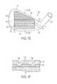
- FIG. 1Ais an exploded view of a representative embodiment of an iron-type golf club head.
- FIG. 1Bis an elevational view of a head body of the iron-type golf club head of FIG. 1A .
- FIG. 1Cis an elevational view of a striking plate of the iron-type golf club head of FIG. 1A .
- FIG. 1Dis a sectional view of a portion of the striking plate of FIG. 1C .
- FIG. 1Eis an elevational view of the iron-type golf club head of FIG. 1A .
- FIG. 1Fis a partial sectional view of the iron-type golf club head of FIG. 1A .
- FIG. 2Ais an exploded view of another representative embodiment of an iron-type golf club head.
- FIG. 2Bis a sectional view of a portion of a striking plate of the iron-type golf club head of FIG. 2A .
- FIG. 2Cis a sectional view of a portion of an intermediate plate of the iron-type golf club head of FIG. 2A .
- FIG. 2Dis a partial sectional view of the iron-type golf club head of FIG. 2A .
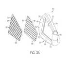
- FIG. 3Ais an exploded view of another representative embodiment of an iron-type golf club head.
- FIG. 3Bis a sectional view of a portion of a striking plate of the iron-type golf club head of FIG. 3A .
- FIG. 3Cis a sectional view of a portion of an intermediate plate of the iron-type golf club head of FIG. 3A .
- FIG. 3Dis a partial sectional view of the iron-type golf club head of FIG. 3A .
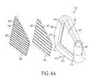
- FIG. 4Ais an exploded view of another representative embodiment of an iron-type golf club head.
- FIG. 4Bis a sectional view of a portion of a striking plate of the iron-type golf club head of FIG. 4A .
- FIG. 4Cis a sectional view of a portion of an intermediate plate of the iron-type golf club head of FIG. 4A .
- FIG. 4Dis a partial sectional view of the iron-type golf club head of FIG. 4A .
- FIG. 5Ais an exploded view of another representative embodiment of an iron-type golf club head.
- FIG. 5Bis a sectional view of a portion of a striking plate of the iron-type golf club head of FIG. 5A .
- FIG. 5Cis a sectional view of a portion of an intermediate plate of the iron-type golf club head of FIG. 5A .
- FIG. 5Dis a partial sectional view of the iron-type golf club head of FIG. 5A .
- FIG. 6is a flowchart showing steps included in an embodiment of a method for manufacturing a golf club head.
- an iron-type golf club headproviding desired precision, durability, and manufacturability are described herein.
- the iron-type golf club headhas a striking plate or contact plate that is manufactured using an electroforming process, then attached to a club head body in a separate assembly step.
- the electroforming processprovides the ability to manufacture striking plates (and other golf club components) with a high degree of precision, and to achieve manufacturing yield rates that are much higher than the rates achieved by previous striking plate manufacturing processes.
- iron-type golf club head striking plates manufactured using an electroforming processachieve greater hardness and durability than comparable striking plates manufactured using previous processes.
- a representative iron-type club head 100includes a head body 110 and a striking plate or contact plate 130 .
- the head body 110includes a heel 112 , a toe 113 , a top line 114 , a sole 116 , and a hosel 140 configured to attach the club head 100 to a shaft (not shown in FIGS. 1A-1F ).
- the head body 110defines a striking plate mounting region 121 configured to receive the striking plate 130 .
- Club head massmay be distributed about the perimeter of the club body 110 based on a particular mass distribution for the club head 100 selected by a club head designer. Perimeter weighting can take various forms.
- One designincludes a sole bar or other mass at or near the club head sole 116 to provide a center of gravity that is situated low in the club head 100 and behind the striking plate 130 as viewed from a striking surface 132 of the club head.
- Other designsinclude mass distributed to the heel 112 and/or toe 113 regions of the perimeter of the club head body 110 to achieve desired performance.
- positions and spacings of club components and featuresare described with respect to a club as situated in a normal address position with the sole 116 resting upon a flat ground plane.
- Directions from a club face toward a golf ballare referred to as forward, and directions away from the golf ball are referred to as rearward.
- Directions noted as up and downare vertically up and down with the club situated in the normal address position.
- normal address positionmeans the club head position wherein a vector normal to the center of the club face substantially lies in a first vertical plane (i.e., a vertical plane is perpendicular to the ground plane), a centerline axis of the hosel 140 substantially lies in a second vertical plane, and the first vertical plane and the second vertical plane substantially perpendicularly intersect.
- the center of the club faceis determined using the procedures described in the USGA “Procedure for Measuring the Flexibility of a Golf Clubhead,” Revision 2.0, Mar. 25, 2005.
- the striking plate 130 and the head body 110are preferably formed separately.
- the completed club headis made by securing the striking plate 130 to the mounting area 121 by bonding with an adhesive, welding, or other process.
- the mounting area 121defines a recess, or pocket, formed in the forward surface of the club head body 110 .
- the perimeter of the recess defined by the mounting area 121is slightly larger than the perimeter of the striking plate 130 , thereby providing for the ability to position the striking plate 130 into the recess.
- a gap or seam 124is thereby defined between the walls of the recess of the mounting area 121 and the perimeter of the striking plate 130 .
- the seam 124has a width that is preferably less than about 0.5 mm, such as less than about 0.25 mm, such as less than about 0.1 mm.
- the club head body 110does not include a recessed mounting area 121 . Instead, the striking plate 130 is secured directly to the forward-facing surface of the club head body 110 , and no gap or seam 124 is formed.
- a front surface 122 of the clubis defined by both a striking surface 132 of the striking plate 130 and portions 126 , 127 of the club body 110 .
- the front surface 122can be polished, blasted using an abrasive media, or ground to remove any front surface edges situated at the striking plate/club body seam 124 .
- the portions 126 , 127are polished and the front surface 132 of the striking plate 130 is finely ground.
- either or both of the portions 126 , 127 and the front surface 132 of the striking plate 130 and other portions of the club headmay include a coating, such as a physical vapor deposition (PVD) coating using the processes described in U.S. patent application Ser. No.
- PVDphysical vapor deposition
- the striking surface 132is a substantially planar grooved surface configured to strike a golf ball, although for some players, other portions of the front surface 122 also contact the golf ball.
- grinding, blasting, and/or polishing operationscan be used to remove any excess material or irregularities introduced in the bonding, welding, or other process, or to provide a selected club head appearance such as, for example, a specularly reflective polished appearance, a fine ground appearance, or other appearance.
- Another alternative surface treatmentincludes applying a PVD coating to the striking plate 130 prior to attachment to the club head body 110 .
- a single layer of a titanium carbide containing materialis applied having a thickness of less than 1 micrometer, such as about 0.4 to 0.6 micrometer.
- the striking plate 130preferably includes a set of grooves, such as exemplary grooves 135 , 136 formed in the striking surface 132 .
- the striking plate 130may also include an additional surface texture, such as secondary surface markings 137 (see, e.g., FIGS. 1D and 1F ).
- the thickness of the striking plate 130can be selected to reduce mass associated with the striking plate 130 , so that additional mass can be distributed to other parts of the club head to achieve intended club design goals.
- the striking plate thicknessis selected consistent with long term club use to avoid premature striking plate failure due to fatigue cracking and other such failure modes, and redistributed mass is situated low on the club head and rearward of the striking plate 130 or wherever needed to dictate a desired performance.
- the striking plate 130is subject to numerous high speed impacts with a golf ball, and should resist permanent deformation. Different types of irons (e.g., long irons and short irons) can experience different forces in golf ball impacts, and the striking plate thickness can be adjusted accordingly, if desired.
- the striking plate 130 and the head body 110are preferably formed separately.
- the head body 110is formed by casting, forging, stamping, or other known manufacturing process.
- materials that can be used to form the head body 110include, without limitation, carbon steels (e.g., 1020 or 8620 carbon steel), stainless steels (e.g., 304, 410, or 431 stainless steel), PH (precipitation-hardenable) alloys (e.g., 17-4, C450, or C455 alloys), titanium alloys (e.g., 3-2.5, 6-4, SP700, 15-3-3-3, 10-2-3, or other alpha/near alpha, alpha-beta, and beta/near beta titanium alloys), aluminum/aluminum alloys (e.g., 3000 series alloys, 5000 series alloys, 6000 series alloys, such as 6061-T6, and 7000 series alloys, such as 7075), magnesium alloys, copper alloys, nickel alloys, glass fiber reinforced
- the striking plate 130is formed using an electroforming process.
- Electroformingis a metal forming process that forms objects by plating a metal layer onto a base form, known as a mandrel, which is removed after plating.
- a mandrelwhich is removed after plating.
- the electroforming processdiffers from electroplating in that the object formed on the mandrel is much thicker and can exist as a self-supporting structure when the mandrel is removed.
- Electroformingprovides the ability to replicate a mandrel surface precisely atom-by-atom with practically no loss of fidelity.
- an electrolytic bathis used to deposit nickel, cobalt, nickel-cobalt alloy, or other electroplatable metal/metal alloy onto a conductive patterned surface, such as coated glass, stainless steel, or other conductive metallic surface.
- a conductive patterned surfacesuch as coated glass, stainless steel, or other conductive metallic surface.
- Electroformingachieves higher precision in comparison to other basic metal forming processes (e.g., casting, forging, stamping, and machining).
- an electroformed membermay be formed to dimensional tolerances, complexity, and/or light weight that are not possible with the foregoing metal forming processes.
- Electroformed metal and metal alloysalso demonstrate superior properties over wrought metal due to their refined crystal structure. Multiple layers of electroformed metal can be molecularly bonded together, or to different substrate materials to produce complex structures with “grown-on” projections. Tolerances of 1.5 to 3 nanometers are possible.
- a masteris provided 610 using any known method, such as by forming scorelines or grooves and other surface texture markings onto a metal sheet (e.g., 304 stainless steel) by milling, etching, or other suitable methods.
- the surface markings on the masterare constructed to a very tight tolerance, because they will be replicated very precisely during the electroforming process.
- the mastercomprises a sheet having a length and width sufficient to accommodate several striking plates (e.g., about 4 to about 16 or more) being formed and subsequently cut into discrete striking plates from an electroformed sheet.
- each mandrelis constructed of a metal or metal alloy using an electroforming process.
- the mastermay be placed into an electrolytic bath, and a metallic or metal alloy mandrel is grown on the surface of the master.
- the mandrelis formed of a nickel-cobalt alloy discussed in more detail below, though other suitable electroforming materials may be used.
- the master/mandrelis removed from the electrolytic bath, and the mandrel is removed from the master.
- the front (mating) surface of the mandrelis a precise negative of the front (mating) surface of the master, thereby allowing the mandrel to be used to create a striking plate sheet that has surface markings that are an exact replica of the master.
- the mandrelis then prepared for use in forming the striking plates. Additional mandrels may be manufactured using the master and the procedure described.
- one or more mandrelsare then placed into an electrolytic bath, and a metallic or metal alloy striking plate sheet is grown on the surface of the mandrel 630 .
- the striking plate sheetincludes the identical surface markings that are contained on the master from which the mandrel was created, to a very high degree of precision.
- the striking plate sheetis formed to a desired thickness—i.e., the desired thickness of the striking plate discussed below—after which the electroformed striking plate sheet and mandrel are removed from the electrolytic bath.
- the striking plate sheetis then removed or separated from the mandrel 640 .
- the striking plate sheetis then prepared for cutting out individual striking plates, and the mandrel is prepared for re-use in electroforming additional striking plate sheets.
- an electroformed striking plate sheethas a size and dimensions sufficient to accommodate a plurality of individual striking plates.
- a single electroformed striking plate sheetmay accommodate from about 4 to about 16 or more striking plates.
- the individual striking platesare cut from the sheet 650 .
- the striking platesare cut from the striking plate sheet via laser cutting, though other methods (e.g., die cutting, wire EDM, water jet, CNC milling, or the like) are used in alternative embodiments.
- the striking platesare then prepared for attachment to the club head body, such as by using a blasting media to enhance adhesion followed by a general cleaning, and are then attached via adhesive bonding, welding, or other suitable method 660 .
- FIGS. 1C and 1Dshow an embodiment of a striking plate 130 produced using the electroforming processes described above.
- the striking plate 130includes a plurality of scorelines or grooves 135 , 136 and an additional plurality of surface texture markings 137 formed on the forward striking surface 132 .
- the striking plate rear surface 133includes a plurality of projections 138 defining a plurality of recesses 139 therebetween.
- all of the foregoing surface features located on the striking surface 132 and rear surface 133 of the striking plate 130are formed simultaneously during the electroforming process.
- the scorelines or grooves and any additional surface texture markingsare cut or etched into the surfaces of the striking plate in separate processes after the striking plate is formed.
- the electroforming processes described hereinprovide the ability to form the scorelines or grooves 135 , 136 , surface texture markings 137 , projections 138 , recesses 139 , and other striking plate surface features as a part of the same metal/metal alloy growing process by which the striking plate 130 is created during the electroforming process.
- the electroforming processincludes creating a striking plate sheet grown on a mandrel in an electrolytic bath.
- metals or metal alloysthat are suitable for use in forming the electroformed striking plate sheet.
- suitable metalsinclude nickel, cobalt, manganese, iron, and tungsten.
- Nickel alloysfor example, have higher strength by the addition of cobalt and/or manganese.
- a suitable materialis a cobalt-tungsten alloy.
- the hardness of the striking plateranges from about 300 HV (Vickers Hardness) to about 700 HV, or from about 30 HRC (Rockwell Scale) to about 60 HRC.
- the striking plate 130is substantially flat, having a nominal front surface to rear surface thickness, t 1 , and a front surface to rear projection thickness, t 2 .
- the front surface to rear surface thickness t 1is the cross-sectional thickness of the striking plate 130 as measured between a location on the front surface 132 between the land areas located between the scorelines or grooves 135 , 136 and other surface texture markings 137 , and a corresponding location defined at the bottom of a recess 139 on the rear surface 133 of the striking plate.
- the values for the front surface to rear surface thickness t 1 and front surface to rear projection thickness t 2 of the striking plate 130will depend upon the electroforming process.
- the striking plate thicknessis selected consistent with long term club use to avoid premature striking plate failure due to fatigue cracking and other such failure modes.
- the striking plate 130is subject to numerous high speed impacts with a golf ball, and should resist permanent deformation.
- different types of iron-type golf clubse.g., long irons, short irons, wedges
- the striking plate thicknesscan be adjusted accordingly, as desired.
- the value for the front surface to rear surface thickness, t 1is from about 0.20 to about 0.50 mm, such as from about 0.20 to about 0.40 mm, such as from about 0.20 to about 0.30 mm.
- the value for the front surface to rear projection thickness, t 2is from about 0.25 to about 1.00 mm, such as from about 0.40 to about 0.90 mm, such as from about 0.50 to about 0.80 mm.
- the electroforming processes described hereinare capable of providing scorelines or grooves 135 , 136 and/or surface texture markings 137 and other features having a broad range of sizes and shapes, and/or having a broad range of cross-sectional profiles.
- the electroforming processes described hereinare capable of providing these designs with a high degree of precision, and with a manufacturing yield that is much higher than the manufacturing yield provided by conventional striking plate manufacturing methods, such as casting, forging, milling, etc.
- the scorelines or grooves 135 , 136 and surface texture markings 137each have bottom surfaces and side walls that define nominal depth and width dimensions. The transitions between the bottom surfaces and the side walls are radiused to provide smooth transitions.
- the scorelines or grooves 135 , 136may include radii of curvature that are typically less than about 0.55 mm, such as less than about 0.50 mm.
- the scorelines or grooves 135 , 136have a depth of from about 0.01 mm to about 0.50 mm, and a width of less than about 0.90 mm, such as from about 0.50 mm to about 0.90 mm. Additional embodiments and details concerning the size and shape of the scorelines or grooves is set forth in U.S. Pat. No. 6,814,673, which is incorporated by reference herein.
- the surface texture markings 137also have bottom surfaces and side walls that define nominal depth and width dimensions.
- the surface texture markings 137have a geometric shape having a depth of from about 0.005 mm to about 0.018 mm, and a width of from about 0.10 mm to about 0.20 mm.
- the geometric shapespreferably all have the same size and shape, preferably square or diamond, although other shapes, e.g., circles, triangles, etc. and/or varieties of shapes and/or sizes, alternatively could be used.
- the geometric shapesare preferably uniformly distributed over the reference areas of the front surface 132 of the striking plate, which is defined between each pair of adjacent scorelines or grooves 135 , 136 .
- the front surface 132 of the striking plateincludes an engineered texture such as the geometric shapes, designs, and patterns described in U.S. Pat. No. 7,445,561, which is incorporated by reference herein.
- the grooves 135 , 136 and surface texture markings 137have dimensions, transition radii, and other parameters selected so as to conform to the Rules of Golf.
- the recesses 139will have a width, t 4 , that is generally narrower than the spacing between adjacent scorelines or grooves 135 , 136 on the front surface of the striking plate.
- the cross-sections of the rear surface projections 138 and recesses 139 shown in FIG. 1Dare merely one example, as square, trapezoidal, semicircular, triangular, or other shapes for the projections and/or recesses can be used.
- different cross-sectional shapes and dimensionscan be used in different portions of the striking plate 130 .
- FIG. 1Fshows a partial cross-section of the striking plate 130 after it has been attached to the club head body 110 .
- the striking plate 130may be attached to the club head body 110 by adhesive bonding, welding, brazing, soldering, diffusion bonding, mechanical fastening, riveting, screwing, etc.
- the striking plate 130is attached to the club head body 110 by a layer of adhesive material 134 , such as an epoxy or polyurethane adhesive.
- the adhesive material 134is 3M® DP460, though other suitable adhesive materials may be used.
- the adhesive 134is applied so as to fill the gap completely between the striking plate 130 and the club head body 110 within the mounting region 121 .
- the thickness of the layer of adhesive material 134is preferably between about 0.05 mm to about 0.4 mm, such as from about 0.07 mm to about 0.15 mm, such as about 0.1 mm.
- the foregoing measurementswould apply to the area of the thinnest layer of adhesive material.
- the rear surface 133 of the striking plate and/or the surface of the mounting region 121 of the club head bodyare treated prior to attachment of the striking plate.
- the rear surface 133 of the striking faceis subjected to a media blasting process, e.g., using sand or ceramic glass beads to slightly roughen the surface to enhance the strength of the adhesive bond.
- the rear surface 133 of the striking faceis subjected to a media blast using low pressure and a grit size of between about 100 mesh to about 400 mesh, such as, for example, between about 180 mesh and about 320 mesh, prior to bonding the striking plate 130 to the club head body 110 .
- one or more optional backing platesare positioned between the striking plate and the head body.
- one, two, three, or four or more backing platesare positioned between the striking plate and the head body.
- the one or more optional backing platesmay be included to obtain any of several performance advantages, such as to improve the durability of the striking plate and/or the club head, to improve the sound or feel of the club head upon impact with a golf ball, or to improve other performance objectives. These performance advantages can be achieved, or enhanced, by providing one or more backing plates having particular structures, geometries, materials, material properties, etc.
- materials that can be used to form the one or more optional backing plates described hereininclude, without limitation: metals (e.g., titanium, steel, aluminum, magnesium, etc.); metal alloys (e.g., nickel alloys, cobalt alloys, molybdenum alloys, combinations, etc.); metallic materials; viscoelastic elastomers; vinyl copolymers with or without inorganic fillers; polyvinyl acetate with or without mineral fillers such as barium sulfate; acrylics; polyesters; polyurethanes; polyethers; polyamides; polybutadienes; polystyrenes; polyisoprenes; polyethylenes; polyolefins; styrene/isoprene block copolymers; metallized polyesters; metallized acrylics; epoxies; epoxy and graphite composites; natural and synthetic rubbers; ceramic materials; piezoelectric ceramics; thermoset and thermoplastic polymers or rubbers; foamed polymers;
- the metallized polyesters and acrylicscan comprise aluminum as the metal.
- Commercially available materialsinclude resilient polymeric materials such as ScotchdampTM from 3M, Sorbothane® from Sorbothane, Inc., DYAD® and GP® from Soundcoat Company Inc., Dynamat® from Dynamat Control of North America, Inc., NoViFlexTM Sylomer® from Pole Star Maritime Group, LLC, Isoplast® from The Dow Chemical Company, and LegetolexTM from Piqua Technologies, Inc.
- FIGS. 2A-2Danother embodiment of a representative iron-type club head 200 includes a head body 210 and a striking plate or contact plate 230 .
- the head body 210includes a heel 212 , a toe 213 , a top line 214 , a sole 216 , and a hosel 240 configured to attach the club head 200 to a shaft (not shown in FIGS. 2A-2D ).
- the head body 210defines a striking plate mounting region 221 configured to receive the striking plate 230 and an optional backing plate 250 .
- Club head massmay be distributed about the perimeter of the club body 210 based on a particular mass distribution for the club head 200 selected by a club head designer, as discussed previously in reference to the embodiment illustrated in FIGS. 1A-1F .
- the striking plate 230 , the optional backing plate 250 , and the head body 210are preferably formed separately.
- the completed club headis made by securing the striking plate 230 and the optional backing plate 250 to the mounting area 221 by bonding with an adhesive, welding, or other process.
- the mounting area 221defines a recess, or pocket, formed in the forward surface of the club head body 210 .
- the perimeter of the recess defined by the mounting area 221is slightly larger than the perimeter of the striking plate 230 and the optional backing plate 250 , thereby providing for the ability to position the striking plate 230 and backing plate 250 into the recess.
- a gap or seam 224is thereby defined between the walls of the recess of the mounting area 221 and the perimeter of the striking plate 230 .
- the seam 224has a width that is preferably less than about 0.5 mm, such as less than about 0.25 mm, such as less than about 0.1 mm.
- the club head body 210does not include a recessed mounting area 221 . Instead, the striking plate 230 and optional backing plate 250 are secured directly to the forward-facing surface of the club head body 210 , and no gap or seam 224 is formed.
- a front surface 222 of the clubis defined by both a striking surface 232 of the striking plate 230 and portions 226 of the club body 210 .
- the front surface 222can be polished, blasted using an abrasive media, or ground to remove any front surface edges situated at the striking plate/club body seam 224 .
- the portions 226are polished and the front surface 232 of the striking plate 230 is finely ground.
- the striking surface 232is a substantially planar grooved surface configured to strike a golf ball, although for some players, other portions of the front surface 222 also contact the golf ball.
- the striking plate 230preferably includes a set of grooves, such as exemplary grooves 235 , 236 formed in the striking surface 232 .
- the striking plate 230may also include an additional surface texture, such as secondary surface markings 237 (see, e.g., FIGS. 2B and 2D ).
- the grooves 235 , 236 and secondary surface markings 237are similar to those described previously in reference to the embodiment illustrated in FIGS. 1A-1F .
- the head body 210is formed by casting, forging, stamping, or other known manufacturing process, using the processes and materials described above in reference to the embodiment illustrated in FIGS. 1A-1F .
- the striking plate 230is formed using an electroforming process, which is also described above in relation to the embodiments illustrated in FIGS. 1A-1F .
- the striking plate 230includes pluralities of projections 238 and recesses 239 on its rear surface, and includes thickness ranges for the thicknesses t 1 , t 2 , t 3 , and t 4 as described above in relation to the striking plate 130 illustrated in FIGS. 1A-1F .
- 2Bare merely one example, as square, trapezoidal, semicircular, triangular, or other shapes for the projections and/or recesses can be used. Moreover, different cross-sectional shapes and dimensions can be used in different portions of the striking plate 230 .
- the optional backing plate 250includes a forward surface 252 and a rear surface 253 .
- the backing plate 250is substantially flat on both its forward surface 252 and rear surface 253 , having a substantially uniform thickness t 5 .
- the thickness t 5will be dependent upon the material of the backing plate and the desired performance objective for including the backing plate, among other factors.
- the backing plate 250has a thickness of from about 0.1 mm to about 3.0 mm, such as from about 0.5 mm to about 2.0 mm, such as from about 1.0 mm to about 1.5 mm.
- the striking plate 230 and backing plate 250can be attached to the club head body 210 by adhesive bonding, soldering, brazing, welding, mechanical fastening, riveting, screwing, etc.
- the backing plate 250is attached to the club head body 210 by a first adhesive layer 254
- the striking plate 230is attached to the backing plate 250 by a second adhesive layer 234 .
- the adhesive materials used in the first adhesive layer 254 and second adhesive layer 234can be the same as those used in the adhesive layer 134 described above in relation to the embodiments illustrated in FIGS. 1A-F .
- FIGS. 3A-3Danother embodiment of a representative iron-type club head 300 includes a head body 310 and a striking plate or contact plate 330 .
- the head body 310includes a heel 312 , a toe 313 , a top line 314 , a sole 316 , and a hosel 340 configured to attach the club head 300 to a shaft (not shown in FIGS. 3A-3D ).
- the head body 310defines a striking plate mounting region 321 configured to receive the striking plate 330 and an optional backing plate 350 .
- Club head massmay be distributed about the perimeter of the club body 310 based on a particular mass distribution for the club head 300 selected by a club head designer, as discussed previously in reference to the embodiment illustrated in FIGS. 1 A- 1 F.]
- the striking plate 330 , the optional backing plate 350 , and the head body 310are preferably formed separately.
- the completed club headis made by securing the striking plate 330 and the optional backing plate 350 to the mounting area 321 by bonding with an adhesive, welding, or other process.
- the mounting area 321defines a recess, or pocket, formed in the forward surface of the club head body 310 .
- the perimeter of the recess defined by the mounting area 321is slightly larger than the perimeter of the striking plate 330 and the optional backing plate 350 , thereby providing for the ability to position the striking plate 330 and backing plate 350 into the recess.
- a gap or seam 324is thereby defined between the walls of the recess of the mounting area 321 and the perimeter of the striking plate 330 .
- the seam 324has a width that is preferably less than about 0.5 mm, such as less than about 0.25 mm, such as less than about 0.1 mm.
- the club head body 310does not include a recessed mounting area 321 . Instead, the striking plate 330 and optional backing plate 350 are secured directly to the forward-facing surface of the club head body 310 , and no gap or seam 324 is formed.
- a front surface 322 of the clubis defined by both a striking surface 332 of the striking plate 330 and portions 326 of the club body 310 .
- the front surface 322can be polished, blasted using an abrasive media, or ground to remove any front surface edges situated at the striking plate/club body seam 324 .
- the portions 326are polished and the front surface 332 of the striking plate 330 is finely ground.
- the striking surface 332is a substantially planar grooved surface configured to strike a golf ball, although for some players, other portions of the front surface 322 also contact the golf ball.
- the striking plate 330preferably includes a set of grooves, such as exemplary grooves 335 , 336 formed in the striking surface 332 .
- the striking plate 330may also include an additional surface texture, such as secondary surface markings 337 (see, e.g., FIGS. 3B and 3D ).
- the grooves 335 , 336 and secondary surface markings 337are similar to those described previously in reference to the embodiment illustrated in FIGS. 1A-1F .
- the head body 310is formed by casting, forging, stamping, or other known manufacturing process, using the processes and materials described above in reference to the embodiment illustrated in FIGS. 1A-1F .
- the striking plate 330is formed using an electroforming process, which is also described above in relation to the embodiments illustrated in FIGS. 1A-1F .
- the striking plate 330includes pluralities of projections 338 and recesses 339 on its rear surface, and includes thickness ranges for the thicknesses t 1 , t 2 , t 3 , and t 4 as described above in relation to the striking plate 130 illustrated in FIGS. 1A-1F .
- the optional backing plate 350includes a forward surface 352 and a rear surface 353 .
- the backing plate 350is substantially flat on its rear surface 353 , and includes a plurality of projections 356 and recesses 357 on its forward surface 352 .
- the thickness t 6 of the backing plate 350 at the location of a recess 357may be from about 0.1 mm to about 3.0 mm, such as from about 0.20 mm to about 2.0 mm, such as from about 0.25 mm to about 1.0 mm.
- the thickness t 7 of the backing plate 350 at a location of a projection 356may be from about 0.25 mm to about 3.25 mm, such as from about 0.40 mm to about 2.5 mm, such as from about 0.50 mm to about 1.0 mm.
- the width (t 8 ) of the recesses 357is substantially equal to the width of the reference areas between the grooves 335 , 336 formed on the striking surface of the striking plate 330
- the width (t 9 ) of the projections 356is substantially equal to the width of the grooves 335 , 336 on the striking plate 330 .
- 3C-3Dare merely one example, as square, trapezoidal, semicircular, triangular, or other shapes for the projections and/or recesses can be used. Moreover, different cross-sectional shapes and dimensions can be used in different portions of the backing plate 350 .
- the projections 356 and recesses 357 on the forward surface of the backing plateare generally aligned, center-to-center, with respective ones of the recesses 339 and projections 338 formed on the rear surface of the striking plate 330 , respectively.
- the adhesive layer 334 located between the striking plate 330 and the backing plate 350may have a substantially uniform thickness across the contact area between the adhesive layer 334 and the backing plate 350 and striking plate 330 .
- the alignment of the projections and recessesare reversed, such that the respective projections are aligned with each other and the respective recesses are aligned with each other.
- the alignment of the striking plate and backing plate, as well as the striking plate projections and recesses and backing plate projections and recessesmay be varied to provide one or more desired performance objectives.
- the backing plate thicknesses t 6 , t 7will be dependent upon the material of the backing plate 350 and the desired performance objectives for including the backing plate, among other factors.
- the striking plate 330 and backing plate 350can be attached to the club head body 310 by adhesive bonding, soldering, brazing, welding, mechanical fastening, riveting, screwing, etc.
- the backing plate 350is attached to the club head body 310 by a first adhesive layer 354
- the striking plate 330is attached to the backing plate 350 by a second adhesive layer 334 .
- the adhesive materials used in the first adhesive layer 354 and second adhesive layer 334can be the same as those used in the adhesive layer 134 described above in relation to the embodiments illustrated in FIGS. 1A-F .
- FIGS. 4A-4Danother embodiment of a representative iron-type club head 400 includes a head body 410 and a striking plate or contact plate 430 .
- the head body 410includes a heel 412 , a toe 413 , a top line 414 , a sole 416 , and a hosel 440 configured to attach the club head 400 to a shaft (not shown in FIGS. 4A-4D ).
- the head body 410defines a striking plate mounting region 421 configured to receive the striking plate 430 and an optional backing plate 450 .
- Club head massmay be distributed about the perimeter of the club body 410 based on a particular mass distribution for the club head 400 selected by a club head designer, as discussed previously in reference to the embodiment illustrated in FIGS. 1A-1F .
- the striking plate 430 , the optional backing plate 450 , and the head body 410are preferably formed separately.
- the completed club headis made by securing the striking plate 430 and the optional backing plate 450 to the mounting area 421 by bonding with an adhesive, welding, or other process.
- the mounting area 421defines a recess, or pocket, formed in the forward surface of the club head body 410 .
- the perimeter of the recess defined by the mounting area 421is slightly larger than the perimeter of the striking plate 430 and the optional backing plate 450 , thereby providing for the ability to position the striking plate 430 and backing plate 450 into the recess.
- a gap or seam 424is thereby defined between the walls of the recess of the mounting area 421 and the perimeter of the striking plate 430 .
- the seam 424has a width that is preferably less than about 0.5 mm, such as less than about 0.25 mm, such as less than about 0.1 mm.
- the club head body 410does not include a recessed mounting area 421 . Instead, the striking plate 430 and optional backing plate 450 are secured directly to the forward-facing surface of the club head body 410 , and no gap or seam 424 is formed.
- a front surface 422 of the clubis defined by both a striking surface 432 of the striking plate 430 and portions 426 of the club body 410 .
- the front surface 422can be polished, blasted using an abrasive media, or ground to remove any front surface edges situated at the striking plate/club body seam 424 .
- the portions 426are polished and the front surface 432 of the striking plate 430 is finely ground.
- the striking surface 432is a substantially planar grooved surface configured to strike a golf ball, although for some players, other portions of the front surface 422 also contact the golf ball.
- the striking plate 430preferably includes a set of grooves, such as exemplary grooves 435 , 436 formed in the striking surface 432 .
- the striking plate 430may also include an additional surface texture, such as secondary surface markings 437 (see, e.g., FIGS. 4B and 4D ).
- the grooves 435 , 436 and secondary surface markings 437are similar to those described previously in reference to the embodiment illustrated in FIGS. 1A-1F .
- the head body 410is formed by casting, forging, stamping, or other known manufacturing process, using the processes and materials described above in reference to the embodiment illustrated in FIGS. 1A-1F .
- the striking plate 430is formed using an electroforming process, which is also described above in relation to the embodiments illustrated in FIGS. 1A-1F .
- the striking plate 430includes pluralities of projections 438 and recesses 439 on its rear surface, and includes thickness ranges for the thicknesses t 1 , t 2 , t 3 , and t 4 as described above in relation to the striking plate 130 illustrated in FIGS. 1A-1F .
- 4Bare merely one example, as square, trapezoidal, semicircular, triangular, or other shapes for the projections and/or recesses can be used. Moreover, different cross-sectional shapes and dimensions can be used in different portions of the striking plate 430 .
- the optional backing plate 450includes a forward surface 452 and a rear surface 453 .
- the backing plate 450is substantially flat on its rear surface 453 , and includes a plurality of projections 456 and recesses 457 on its forward surface 452 .
- the thickness t 10 of the backing plate 450 at the location of a recess 457may be from about 0.1 mm to about 3.0 mm, such as from about 0.20 mm to about 2.0 mm, such as from about 0.25 mm to about 1.0 mm.
- the thickness t 11 of the backing plate 450 at a location of a projection 456may be from about 0.25 mm to about 3.25 mm, such as from about 0.40 mm to about 2.5 mm, such as from about 0.50 mm to about 1.0 mm.
- the width (t 12 ) of the recesses 457is substantially equal to the width of the recesses 439 formed on the rear surface of the striking plate 430
- the width (t 13 ) of the projections 456is substantially equal to the width of the projections 438 formed on the rear surface of the striking plate 430 .
- 4C-4Dare merely one example, as square, trapezoidal, semicircular, triangular, or other shapes for the projections and/or recesses can be used. Moreover, different cross-sectional shapes and dimensions can be used in different portions of the backing plate 450 .
- the backing plate thicknesses t 10 , t 11will be dependent upon the material of the backing plate 450 and the desired performance objectives for including the backing plate, among other factors.
- the striking plate 430 and backing plate 450can be attached to the club head body 410 by adhesive bonding, soldering, brazing, welding, mechanical fastening, riveting, screwing, etc.
- the backing plate 450is attached to the club head body 410 by a first adhesive layer 454
- the striking plate 430is attached to the backing plate 450 by a second adhesive layer 434 .
- the adhesive materials used in the first adhesive layer 454 and second adhesive layer 434can be the same as those used in the adhesive layer 134 described above in relation to the embodiments illustrated in FIGS. 1A-F .
- the projections 456 and recesses 457 on the forward surface of the backing plateare generally aligned, center-to-center, with respective ones of the projections 438 and recesses 439 formed on the rear surface of the striking plate 430 , respectively.
- the adhesive layer 434 located between the striking plate 430 and the backing plate 450may have a thickness that alternates between relatively thin sections of the adhesive layer 434 located between aligned striking plate rear projections 438 and backing plate forward projections 456 , and relatively thick sections of the adhesive layer 434 located between aligned striking plate rear recesses 439 and backing plate forward recesses 457 .
- FIGS. 5A-5Danother embodiment of a representative iron-type club head 500 includes a head body 510 and a striking plate or contact plate 530 .
- the head body 510includes a heel 512 , a toe 513 , a top line 514 , a sole 516 , and a hosel 540 configured to attach the club head 500 to a shaft (not shown in FIGS. 5A-5D ).
- the head body 510defines a striking plate mounting region 521 configured to receive the striking plate 530 and an optional backing plate 550 .
- Club head massmay be distributed about the perimeter of the club body 510 based on a particular mass distribution for the club head 500 selected by a club head designer, as discussed previously in reference to the embodiment illustrated in FIGS. 1A-1F .
- the striking plate 530 , the optional backing plate 550 , and the head body 510are preferably formed separately.
- the completed club headis made by securing the striking plate 530 and the optional backing plate 550 to the mounting area 521 by bonding with an adhesive, welding, or other process.
- the mounting area 521defines a recess, or pocket, formed in the forward surface of the club head body 510 .
- the perimeter of the recess defined by the mounting area 521is slightly larger than the perimeter of the striking plate 530 and the optional backing plate 550 , thereby providing for the ability to position the striking plate 530 and backing plate 550 into the recess.
- a gap or seam 524is thereby defined between the walls of the recess of the mounting area 521 and the perimeter of the striking plate 530 .
- the seam 524has a width that is preferably less than about 0.5 mm, such as less than about 0.25 mm, such as less than about 0.1 mm.
- the club head body 510does not include a recessed mounting area 521 . Instead, the striking plate 530 and optional backing plate 550 are secured directly to the forward-facing surface of the club head body 510 , and no gap or seam 524 is formed.
- a front surface 522 of the clubis defined by both a striking surface 532 of the striking plate 530 and portions 526 of the club body 510 .
- the front surface 522can be polished, blasted using an abrasive media, or ground to remove any front surface edges situated at the striking plate/club body seam 524 .
- the portions 526are polished and the front surface 532 of the striking plate 530 is finely ground.
- the striking surface 532is a substantially planar grooved surface configured to strike a golf ball, although for some players, other portions of the front surface 522 also contact the golf ball.
- the striking plate 530preferably includes a set of grooves, such as exemplary grooves 535 , 536 formed in the striking surface 532 .
- the striking plate 530may also include an additional surface texture, such as secondary surface markings 537 (see, e.g., FIGS. 5B and 5D ).
- the grooves 535 , 536 and secondary surface markings 537are similar to those described previously in reference to the embodiment illustrated in FIGS. 1A-1F .
- the head body 510is formed by casting, forging, stamping, or other known manufacturing process, using the processes and materials described above in reference to the embodiment illustrated in FIGS. 1A-1F .
- the striking plate 530is formed using an electroforming process, which is also described above in relation to the embodiments illustrated in FIGS. 1A-1F .
- the striking plate 530includes pluralities of projections 538 and recesses 539 on its rear surface, and includes thickness ranges for the thicknesses t 1 , t 2 , t 3 , and t 4 as described above in relation to the striking plate 130 illustrated in FIGS. 1A-1F .
- 5Bare merely one example, as square, trapezoidal, semicircular, triangular, or other shapes for the projections and/or recesses can be used. Moreover, different cross-sectional shapes and dimensions can be used in different portions of the striking plate 530 .
- the optional backing plate 550includes a forward surface 552 and a rear surface 553 .
- the backing plate 550is substantially flat on both its rear surface 553 and on its forward surface 552 and has a nominal thickness t 16 .
- the thickness t 16 of the backing plate 550may be from about 0.1 mm to about 3.0 mm, such as from about 0.20 mm to about 2.0 mm, such as from about 0.25 mm to about 1.0 mm.
- the backing plate 550includes a plurality of square through-holes 557 that extend completely through the backing plate 550 from the forward surface 552 to the rear surface 553 and that are separated by substantially flat reference areas 556 .
- the width (t 14 ) of the through-holes 557is substantially equal to the width of the projections 538 formed on the rear surface of the striking plate 530
- the width (t 15 ) of the reference areas 556is substantially equal to the width of the recesses 539 formed on the rear surface of the striking plate 530 .
- the locations, sizes, and cross-sectional shapes of the through-holes 557 and reference areas 556 shown in FIGS. 5C-5Dare merely one example, as round, triangular, trapezoidal, rectangular, or other geometric or non-geometric shapes for the through-holes 557 and reference areas 556 can be used.
- different cross-sectional shapes and dimensionscan be used in different portions of the backing plate 550 .
- the backing plate thicknesses t 16will be dependent upon the material of the backing plate 550 and the desired performance objectives for including the backing plate, among other factors.
- the striking plate 530 and backing plate 550can be attached to the club head body 510 by adhesive bonding, soldering, brazing, welding, mechanical fastening, riveting, screwing, etc.
- the backing plate 550is attached to the club head body 510 by a first adhesive layer 554
- the striking plate 530is attached to the backing plate 550 by a second adhesive layer 534 .
- the adhesive materials used in the first adhesive layer 554 and second adhesive layer 534can be the same as those used in the adhesive layer 134 described above in relation to the embodiments illustrated in FIGS. 1A-F .
- the through-holes 557 on the backing plate 550are generally aligned, center-to-center, with respective ones of the recesses 539 formed on the rear surface of the striking plate 530 .
- the through-holes 557may be generally aligned, center-to-center, with respective ones of the projections 538 formed on the rear surface of the striking plate 530 .
- the through-holes 557 of the backing plate 550may have an aligned that is offset by a defined distance from the centers of either the recesses 539 or the projections 538 of the striking plate 530 .
- the striking plate projections 338are aligned with the backing plate recesses 357 , and the striking plate recesses 339 are aligned with the backing plate projections 356 .
- This alignmentresults in a substantially uniform thickness for the adhesive layer 334 located between the striking plate 330 and the backing plate 350 .
- the striking plate projections 438are aligned with the backing plate projections 456 , and the striking plate recesses 439 are aligned with the backing plate recesses 457 .
- This alignmentresults in an adhesive layer 434 located between the striking plate 430 and the backing plate 450 that has a varying thickness.
- the striking plate projections 538are aligned with the backing plate reference areas 556
- the striking plate recesses 539are aligned with the backing plate through-holes 557 .
- This alignmentresults in an second adhesive layer 534 located between the striking plate 530 and the backing plate 550 that has a varying thickness and that extends through the through-holes 557 to meet the first adhesive layer 554 .
- first portions of the striking plate and backing plateinclude projections, recesses, and/or through-holes having a first alignment
- second portions of the striking plate and backing plateinclude projections, recesses, and/or through-holes having a second alignment.
- first portions of the striking plate and backing plateinclude projections, recesses, and/or through-holes while second portions of the striking plate and backing plate do not include projections, recesses, or through-holes.
- first portions of the striking plate and backing plateinclude projections, recesses, and/or through-holes while second portions of the striking plate and backing plate do not include projections, recesses, or through-holes.
- the various shapes, sizes, and orientations of the described embodiments of the striking plates, backing plates, and adhesive layersare selected to achieve desired performance objectives, such as (without limitation) to change (increase or decrease) the coefficient of restitution (COR) and/or characteristic time (CT) at one or more locations of the striking plate, to improve the durability of the striking plate and/or the club head, to improve the sound or feel of the club head upon impact with a golf ball, or to improve other performance objectives.
- CORcoefficient of restitution
- CTcharacteristic time
- the materials and layer thicknesses of these componentsmay also be varied to achieve these objectives.
- the face insertis significantly more durable than a comparable face insert manufactured according to conventional casting or machining processes.
- the electroforming method of manufactureprovides face inserts having increased hardness and durability that are able to withstand a significantly higher number of high speed strikes with a golf ball and that have significantly increased resistance to scratching and scuffing when golf balls are struck in the presence of sand (bunker shots).
- Another advantage of the embodiments described aboveis that the face insert is formed in a more precise manner, leading to a significantly higher manufacturing yield in comparison to casting or machining processes used to manufacture conventional face inserts.
Landscapes
- Chemical & Material Sciences (AREA)
- Engineering & Computer Science (AREA)
- Organic Chemistry (AREA)
- Electrochemistry (AREA)
- Materials Engineering (AREA)
- Metallurgy (AREA)
- Chemical Kinetics & Catalysis (AREA)
- Health & Medical Sciences (AREA)
- General Health & Medical Sciences (AREA)
- Physical Education & Sports Medicine (AREA)
- Crystallography & Structural Chemistry (AREA)
- Mechanical Engineering (AREA)
- Golf Clubs (AREA)
Abstract
Description
Claims (18)
Priority Applications (4)
| Application Number | Priority Date | Filing Date | Title |
|---|---|---|---|
| US13/472,811US9033819B2 (en) | 2012-05-16 | 2012-05-16 | Golf club head with face insert |
| US14/469,123US10046484B2 (en) | 2007-12-19 | 2014-08-26 | Mold and associated methods |
| US14/710,343US9683301B2 (en) | 2012-05-16 | 2015-05-12 | Golf club head with face insert |
| US16/033,976US10500766B2 (en) | 2007-12-19 | 2018-07-12 | Mold and associated methods |
Applications Claiming Priority (1)
| Application Number | Priority Date | Filing Date | Title |
|---|---|---|---|
| US13/472,811US9033819B2 (en) | 2012-05-16 | 2012-05-16 | Golf club head with face insert |
Related Child Applications (1)
| Application Number | Title | Priority Date | Filing Date |
|---|---|---|---|
| US14/710,343DivisionUS9683301B2 (en) | 2012-05-16 | 2015-05-12 | Golf club head with face insert |
Publications (2)
| Publication Number | Publication Date |
|---|---|
| US20130310192A1 US20130310192A1 (en) | 2013-11-21 |
| US9033819B2true US9033819B2 (en) | 2015-05-19 |
Family
ID=49581772
Family Applications (2)
| Application Number | Title | Priority Date | Filing Date |
|---|---|---|---|
| US13/472,811Active2032-11-21US9033819B2 (en) | 2007-12-19 | 2012-05-16 | Golf club head with face insert |
| US14/710,343Active2032-08-09US9683301B2 (en) | 2012-05-16 | 2015-05-12 | Golf club head with face insert |
Family Applications After (1)
| Application Number | Title | Priority Date | Filing Date |
|---|---|---|---|
| US14/710,343Active2032-08-09US9683301B2 (en) | 2012-05-16 | 2015-05-12 | Golf club head with face insert |
Country Status (1)
| Country | Link |
|---|---|
| US (2) | US9033819B2 (en) |
Cited By (16)
| Publication number | Priority date | Publication date | Assignee | Title |
|---|---|---|---|---|
| US20150209630A1 (en)* | 2010-05-11 | 2015-07-30 | Nike, Inc. | Golf Club and Golf Club Heads |
| US20160296809A1 (en)* | 2011-11-28 | 2016-10-13 | Acushnet Company | Co-forged golf club head and method of manufacture |
| US10881926B1 (en) | 2019-07-29 | 2021-01-05 | Taylor Made Golf Company, Inc. | Iron golf club head |
| US11358036B2 (en) | 2012-05-31 | 2022-06-14 | Karsten Manufacturing Corporation | Golf club head or other ball striking device with face having modulus variance |
| US11369848B2 (en)* | 2018-06-06 | 2022-06-28 | Taylor Made Golf Company, Inc. | Golf club head having strike face of non-plated oxidizable metal and rusty face |
| US11707655B2 (en) | 2018-02-12 | 2023-07-25 | Parsons Xtreme Golf, LLC | Golf club heads and methods to manufacture golf club heads |
| US11771962B2 (en) | 2020-08-21 | 2023-10-03 | Wilson Sporting Goods Co. | Faceplate of a golf club head |
| US11806589B2 (en) | 2019-03-11 | 2023-11-07 | Parsons Xtreme Golf, LLC | Golf club heads and methods to manufacture golf club heads |
| US11839799B2 (en) | 2019-01-02 | 2023-12-12 | Parsons Xtreme Golf, LLC | Golf club heads and methods to manufacture golf club heads |
| US11839800B2 (en) | 2018-02-12 | 2023-12-12 | Parsons Xtreme Golf, LLC | Golf club heads and methods to manufacture golf club heads |
| US11938385B1 (en) | 2018-02-12 | 2024-03-26 | Parsons Xtreme Golf, LLC | Golf club heads and methods to manufacture golf club heads |
| US12109464B2 (en) | 2018-02-12 | 2024-10-08 | Parsons Xtreme Golf, LLC | Golf club heads and methods to manufacture golf club heads |
| US12194351B1 (en) | 2021-11-08 | 2025-01-14 | Parsons Xtreme Golf, LLC | Golf club heads and methods to manufacture golf club heads |
| US12233318B2 (en) | 2020-12-29 | 2025-02-25 | Taylor Made Golf Company, Inc. | Golf club heads |
| US12324967B2 (en) | 2018-02-12 | 2025-06-10 | Parsons Xtreme Golf, LLC | Golf club heads and methods to manufacture golf club heads |
| US12434112B2 (en) | 2019-03-11 | 2025-10-07 | Parsons Xtreme Golf, LLC | Golf club heads and methods to manufacture golf club heads |
Families Citing this family (170)
| Publication number | Priority date | Publication date | Assignee | Title |
|---|---|---|---|---|
| US11465018B2 (en)* | 2007-07-25 | 2022-10-11 | Karsten Manufacturing Corporation | Club head sets with varying characteristics and related methods |
| US8979669B2 (en)* | 2010-12-30 | 2015-03-17 | Taylor Made Golf Company, Inc. | Polymer cover layer for golf club face |
| US9108091B1 (en)* | 2011-06-14 | 2015-08-18 | Callaway Golf Company | Golf club weight screws |
| US11918867B2 (en) | 2011-11-28 | 2024-03-05 | Acushnet Company | Co-forged golf club head and method of manufacture |
| US10391370B2 (en)* | 2011-11-28 | 2019-08-27 | Acushnet Company | Co-forged golf club head and method of manufacture |
| US9174100B2 (en)* | 2012-06-22 | 2015-11-03 | Bridgestone Sports Co., Ltd. | Hollow golf club head and method of manufacturing the same |
| US9433835B2 (en)* | 2013-04-01 | 2016-09-06 | Acushnet Company | Golf club head with improved striking face |
| US10864418B2 (en)* | 2013-07-19 | 2020-12-15 | Wilson Sporting Goods Co. | Sports paddle with improved head portion |
| US11235211B2 (en) | 2014-02-20 | 2022-02-01 | Parsons Xtreme Golf, LLC | Golf club heads and methods to manufacture golf club heads |
| US10814193B2 (en) | 2014-02-20 | 2020-10-27 | Parsons Xtreme Golf, LLC | Golf club heads and methods to manufacture golf club heads |
| USD802068S1 (en) | 2016-12-08 | 2017-11-07 | Parsons Xtreme Golf, LLC | Golf club head |
| US9814952B2 (en) | 2014-05-13 | 2017-11-14 | Parsons Xtreme Golf, LLC | Golf club heads and methods to manufacture golf club heads |
| US11731013B2 (en) | 2014-02-20 | 2023-08-22 | Parsons Xtreme Golf, LLC | Golf club heads and methods to manufacture golf club heads |
| US10940375B2 (en) | 2014-07-07 | 2021-03-09 | Parsons Xtreme Golf, LLC | Golf club heads and methods to manufacture golf club heads |
| US11291890B2 (en) | 2017-11-03 | 2022-04-05 | Parsons Xtreme Golf, LLC | Golf club heads and methods to manufacture golf club heads |
| US20170368429A1 (en) | 2014-02-20 | 2017-12-28 | Parsons Xtreme Golf, LLC | Golf club heads and methods to manufacture golf club heads |
| US10729949B2 (en) | 2014-02-20 | 2020-08-04 | Parsons Xtreme Golf, LLC | Golf club heads and methods to manufacture golf club heads |
| USD835737S1 (en) | 2017-02-27 | 2018-12-11 | Parsons Xtreme Golf, LLC | Golf club head |
| US10232235B2 (en) | 2014-02-20 | 2019-03-19 | Parsons Xtreme Golf, LLC | Golf club heads and methods to manufacture golf club heads |
| US9675853B2 (en) | 2014-05-13 | 2017-06-13 | Parsons Xtreme Golf, LLC | Golf club heads and methods to manufacture golf club heads |
| USD863478S1 (en) | 2017-07-20 | 2019-10-15 | Parsons Xtreme Golf, LLC | Golf club head |
| USD764610S1 (en) | 2015-08-25 | 2016-08-23 | Parsons Xtreme Golf, LLC | Golf club head |
| US12290724B2 (en) | 2014-02-20 | 2025-05-06 | Parsons Xtreme Golf, LLC | Golf club heads and methods to manufacture golf club heads |
| US11691056B2 (en) | 2014-02-20 | 2023-07-04 | Parsons Xtreme Golf, LLC | Golf club heads and methods to manufacture golf club heads |
| US10478684B2 (en) | 2014-02-20 | 2019-11-19 | Parsons Xtreme Golf, LLC | Golf club heads and methods to manufacture golf club heads |
| US10729948B2 (en) | 2014-02-20 | 2020-08-04 | Parsond Xtreme Golf, Llc | Golf club heads and methods to manufacture golf club heads |
| US10029159B2 (en) | 2014-02-20 | 2018-07-24 | Parsons Xtreme Golf, LLC | Golf club heads and methods to manufacture golf club heads |
| US10874921B2 (en) | 2014-02-20 | 2020-12-29 | Parsons Xtreme Golf, LLC | Golf club heads and methods to manufacture golf club heads |
| US11458372B2 (en) | 2014-02-20 | 2022-10-04 | Parsons Xtreme Golf, LLC | Golf club heads and methods to manufacture golf club heads |
| US11541288B2 (en) | 2014-02-20 | 2023-01-03 | Parsons Xtreme Golf, LLC | Golf club heads and methods to manufacture golf club heads |
| US11344775B2 (en) | 2014-02-20 | 2022-05-31 | Parsons Xtreme Golf, LLC | Golf club heads and methods to manufacture golf club heads |
| USD746926S1 (en) | 2015-08-25 | 2016-01-05 | Parsons Xtreme Golf, LLC | Golf club head |
| US9649542B2 (en) | 2014-05-13 | 2017-05-16 | Parsons Xtreme Golf, LLC | Golf club heads and methods to manufacture golf club heads |
| US10632349B2 (en) | 2017-11-03 | 2020-04-28 | Parsons Xtreme Golf, LLC | Golf club heads and methods to manufacture golf club heads |
| US11117030B2 (en) | 2014-02-20 | 2021-09-14 | Parsons Xtreme Golf, LLC | Golf club heads and methods to manufacture golf club heads |
| US9764208B1 (en) | 2016-05-31 | 2017-09-19 | Parsons Xtreme Golf, LLC | Golf club heads and methods to manufacture golf club heads |
| US11097168B2 (en) | 2014-02-20 | 2021-08-24 | Parsons Xtreme Golf, LLC | Golf club heads and methods to manufacture golf club heads |
| US11154755B2 (en) | 2014-02-20 | 2021-10-26 | Parsons Xtreme Golf, LLC | Golf club heads and methods to manufacture golf club heads |
| US9199143B1 (en) | 2014-08-25 | 2015-12-01 | Parsons Xtreme Golf, LLC | Golf club heads and methods to manufacture golf club heads |
| US12311239B2 (en) | 2014-02-20 | 2025-05-27 | Parsons Xtreme Golf, LLC | Golf club heads and methods to manufacture golf club heads |
| US11794081B2 (en) | 2014-02-20 | 2023-10-24 | Parsons Xtreme Golf, LLC | Golf club heads and methods to manufacture golf club heads |
| US9533201B2 (en) | 2014-08-25 | 2017-01-03 | Parsons Xtreme Golf, LLC | Golf club heads and methods to manufacture golf club heads |
| US11167187B2 (en) | 2014-02-20 | 2021-11-09 | Parsons Xtreme Golf, LLC | Golf club heads and methods to manufacture golf club heads |
| US12194349B2 (en) | 2017-11-03 | 2025-01-14 | Parsons Xtreme Golf, LLC | Golf club heads and methods to manufacture golf club heads |
| US10596425B2 (en) | 2014-02-20 | 2020-03-24 | Parsons Xtreme Golf, LLC | Golf club heads and methods to manufacture golf club heads |
| USD723120S1 (en) | 2014-10-21 | 2015-02-24 | Parson Xtreme Golf, LLC | Golf club head |
| US10821339B2 (en) | 2014-02-20 | 2020-11-03 | Parsons Xtreme Golf, LLC | Golf club heads and methods to manufacture golf club heads |
| US11141633B2 (en) | 2014-02-20 | 2021-10-12 | Parsons Xtreme Golf, LLC | Golf club heads and methods to manufacture golf club heads |
| US10933286B2 (en) | 2014-02-20 | 2021-03-02 | Parsons Xtreme Golf, LLC | Golf club heads and methods to manufacture golf club heads |
| US10864414B2 (en) | 2014-02-20 | 2020-12-15 | Parsons Xtreme Golf, LLC | Golf club heads and methods to manufacture golf club heads |
| US9468821B2 (en) | 2014-08-25 | 2016-10-18 | Parsons Xtreme Golf, LLC | Golf club heads and methods to manufacture golf club heads |
| US11358039B2 (en) | 2014-02-20 | 2022-06-14 | Parsons Xtreme Golf, LLC | Golf club heads and methods to manufacture golf club heads |
| US11058932B2 (en) | 2014-02-20 | 2021-07-13 | Parsons Xtreme Golf, LLC | Golf club heads and methods to manufacture golf club heads |
| US10596424B2 (en) | 2014-02-20 | 2020-03-24 | Parsons Extreme Golf, Llc | Golf club heads and methods to manufacture golf club heads |
| US10512829B2 (en) | 2014-02-20 | 2019-12-24 | Parsons Xtreme Golf, LLC | Golf club heads and methods to manufacture golf club heads |
| US10874919B2 (en) | 2017-11-03 | 2020-12-29 | Parsons Xtreme Golf, LLC | Golf club heads and methods to manufacture golf club heads |
| US9610481B2 (en) | 2014-02-20 | 2017-04-04 | Parsons Xtreme Golf, LLC | Golf club heads and methods to manufacture golf club heads |
| JP6386277B2 (en)* | 2014-07-09 | 2018-09-05 | ブリヂストンスポーツ株式会社 | Golf club head |
| US9796131B2 (en) | 2014-08-25 | 2017-10-24 | Parsons Xtreme Golf, LLC | Golf club heads and methods to manufacture golf club heads |
| USD767696S1 (en) | 2016-01-21 | 2016-09-27 | Parsons Xtreme Golf, LLC | Golf club head |
| USD807976S1 (en) | 2016-01-21 | 2018-01-16 | Parsons Xtreme Golf, LLC | Golf club head |
| US11684831B2 (en)* | 2017-01-10 | 2023-06-27 | Parsons Xtreme Golf, LLC | Golf club heads and methods to manufacture golf club heads |
| USD746927S1 (en) | 2015-07-17 | 2016-01-05 | Parsons Xtreme Golf, LLC | Golf club head |
| USD786377S1 (en) | 2015-10-21 | 2017-05-09 | Parsons Xtreme Golf, LLC | Golf club head |
| USD773575S1 (en) | 2014-10-21 | 2016-12-06 | Parsons Xtreme Golf, LLC | Golf club head |
| GB2549408B (en)* | 2014-12-11 | 2018-04-25 | Parsons Xtreme Golf Llc | Golf club heads and methods to manufacture golf club heads |
| KR20180084627A (en)* | 2015-01-05 | 2018-07-25 | 파슨스 익스트림 골프, 엘엘씨 | How to make a golf club head and a golf club head |
| CN107249696B (en)* | 2015-02-19 | 2019-03-12 | 帕森斯极致高尔夫有限责任公司 | The method of glof club head and manufacture glof club head |
| JP6435052B2 (en)* | 2015-02-19 | 2018-12-05 | パーソンズ エクストリーム ゴルフ, エルエルシーParsons Xtreme Golf, Llc | Golf club head and golf club head manufacturing method |
| US9937669B2 (en)* | 2015-04-02 | 2018-04-10 | Xerox Corporation | Three-dimensional printed part removal using a bimetallic platen |
| JP5824593B1 (en)* | 2015-06-04 | 2015-11-25 | ダンロップスポーツ株式会社 | Iron type golf club head |
| US20180126230A1 (en)* | 2015-09-24 | 2018-05-10 | Acushnet Company | Golf club |
| US9844709B2 (en)* | 2015-09-24 | 2017-12-19 | Acushnet Company | Golf club striking surface |
| USD802070S1 (en) | 2016-01-21 | 2017-11-07 | Parsons Xtreme Golf, LLC | Golf club head |
| US10343037B2 (en)* | 2016-06-16 | 2019-07-09 | Acushnet Company | Golf club having striking face with supporting wall |
| USD776216S1 (en) | 2016-06-30 | 2017-01-10 | Parsons Xtreme Golf, LLC | Golf club head |
| USD777858S1 (en) | 2016-06-30 | 2017-01-31 | Parsons Xtreme Golf, LLC | Golf club head |
| US10682555B2 (en)* | 2016-07-26 | 2020-06-16 | Sumitomo Rubber Industries, Ltd. | Golf club head with textured striking face |
| US9868037B1 (en) | 2016-07-26 | 2018-01-16 | Dunlop Sports Co., Ltd. | Golf club head with textured striking face |
| USD816787S1 (en) | 2016-10-31 | 2018-05-01 | Parsons Xtreme Golf, LLC | Golf club head |
| USD827065S1 (en) | 2016-12-08 | 2018-08-28 | Parsons Xtreme Golf, LLC | Golf club head |
| USD802069S1 (en) | 2017-01-10 | 2017-11-07 | Parsons Xtreme Golf, LLC | Golf club head |
| US12303750B2 (en) | 2017-01-10 | 2025-05-20 | Parsons Xtreme Golf, LLC | Golf club heads and methods to manufacture golf club heads |
| USD822134S1 (en) | 2017-02-14 | 2018-07-03 | Parsons Xtreme Golf, LLC | Golf club head |
| US11745067B2 (en) | 2017-03-29 | 2023-09-05 | Parsons Xtreme Golf, LLC | Golf club heads and methods to manufacture golf club heads |
| US11426640B2 (en) | 2017-11-03 | 2022-08-30 | Parsons Xtreme Golf, LLC | Golf club heads and methods to manufacture golf club heads |
| US11400352B1 (en) | 2018-02-12 | 2022-08-02 | Parsons Xtreme Golf, LLC | Golf club heads and methods to manufacture golf club heads |
| US11369847B2 (en) | 2019-03-07 | 2022-06-28 | Parsons Xtreme Golf, LLC | Golf club heads and methods to manufacture golf club heads |
| US11192003B2 (en) | 2017-11-03 | 2021-12-07 | Parsons Xtreme Golf, LLC | Golf club heads and methods to manufacture golf club heads |
| USD825891S1 (en) | 2017-04-25 | 2018-08-21 | Parsons Xtreme Golf, LLC | Golf club head |
| JP6871798B2 (en)* | 2017-04-26 | 2021-05-12 | ブリヂストンスポーツ株式会社 | Golf club head |
| USD852303S1 (en) | 2017-07-10 | 2019-06-25 | Parsons Xtreme Golf, LLC | Golf club head |
| USD930100S1 (en) | 2017-07-10 | 2021-09-07 | Parsons Xtreme Golf, LLC | Golf club head |
| USD839372S1 (en) | 2017-09-07 | 2019-01-29 | Parsons Xtreme Golf, LLC | Golf club head |
| USD827745S1 (en) | 2017-07-10 | 2018-09-04 | Parsons Xtreme Golf, LLC | Golf club head |
| USD850551S1 (en) | 2017-07-10 | 2019-06-04 | Parsons Xtreme Golf, LLC | Golf club head |
| USD865886S1 (en) | 2017-07-10 | 2019-11-05 | Parsons Xtreme Golf, LLC | Golf club head |
| JP6347305B1 (en)* | 2017-08-04 | 2018-06-27 | 株式会社プロギア | Golf club head |
| USD856451S1 (en) | 2017-09-25 | 2019-08-13 | Parsons Xtreme Golf, LLC | Golf club head |
| US11707653B2 (en) | 2017-11-03 | 2023-07-25 | Parsons Xtreme Golf, LLC | Golf club heads and methods to manufacture golf club heads |
| US10905920B2 (en) | 2018-12-04 | 2021-02-02 | Parsons Xtreme Golf, LLC | Golf club heads and methods to manufacture golf club heads |
| US12343601B2 (en) | 2017-11-03 | 2025-07-01 | Parsons Xtreme Golf, LLC | Golf club heads and methods to manufacture golf club heads |
| US11642577B2 (en) | 2017-11-03 | 2023-05-09 | Parsons Xtreme Golf, LLC | Golf club heads and methods to manufacture golf club heads |
| US11565158B1 (en) | 2018-02-12 | 2023-01-31 | Parsons Xtreme Golf, LLC | Golf club heads and methods to manufacture golf club heads |
| KR102215194B1 (en) | 2018-02-12 | 2021-02-10 | 파슨스 익스트림 골프, 엘엘씨 | Golf club head and method for manufacturing golf club head |
| US11944880B2 (en) | 2018-02-12 | 2024-04-02 | Parsons Xtreme Golf, LLC | Golf club heads and methods to manufacture golf club heads |
| US11786786B2 (en) | 2018-02-12 | 2023-10-17 | Parsons Xtreme Golf, LLC | Golf club heads and methods to manufacture golf club heads |
| USD852305S1 (en) | 2018-04-23 | 2019-06-25 | Parsons Xtreme Golf, LLC | Golf club head |
| USD852304S1 (en) | 2018-04-23 | 2019-06-25 | Parsons Xtreme Golf, LLC | Golf club head |
| US10828538B2 (en) | 2018-05-04 | 2020-11-10 | Parsons Xtreme Golf, LLC | Golf club heads and methods to manufacture golf club heads |
| USD896903S1 (en) | 2018-06-26 | 2020-09-22 | Parsons Xtreme Golf, LLC | Golf club head |
| USD852302S1 (en) | 2018-07-25 | 2019-06-25 | Parsons Xtreme Golf, LLC | Golf club head |
| USD893647S1 (en) | 2018-07-25 | 2020-08-18 | Parsons Xtreme Golf, LLC | Golf club head |
| USD915535S1 (en) | 2018-07-25 | 2021-04-06 | Parsons Xtreme Golf, LLC | Golf club head |
| USD894302S1 (en) | 2018-07-25 | 2020-08-25 | Parsons Xtreme Golf, LLC | Golf club head |
| USD893648S1 (en) | 2018-07-25 | 2020-08-18 | Parsons Xtreme Golf, LLC | Golf club head |
| US11331545B2 (en)* | 2018-09-14 | 2022-05-17 | Timothy W. Markison | Force focusing golf club |
| USD897462S1 (en) | 2018-10-05 | 2020-09-29 | Parsons Xtreme Golf, LLC | Golf club head |
| USD894301S1 (en) | 2018-11-30 | 2020-08-25 | Parsons Xtreme Golf, LLC | Golf club head |
| USD921787S1 (en) | 2019-03-13 | 2021-06-08 | Parsons Xtreme Golf, LLC | Golf club head |
| USD921786S1 (en) | 2019-03-13 | 2021-06-08 | Parsons Xtreme Golf, LLC | Golf club head |
| USD926900S1 (en) | 2019-05-17 | 2021-08-03 | Parsons Xtreme Golf, LLC | Golf club head |
| WO2020247875A1 (en)* | 2019-06-05 | 2020-12-10 | Karsten Manufacturing Corporation | Multi-material iron golf club head |
| USD927620S1 (en) | 2019-06-14 | 2021-08-10 | Parsons Xtreme Golf, LLC | Golf club head |
| USD930774S1 (en) | 2019-07-15 | 2021-09-14 | Parsons Xtreme Golf, LLC | Golf club head |
| USD933148S1 (en) | 2019-07-15 | 2021-10-12 | Parsons Xtreme Golf, LLC | Golf club head |
| USD930773S1 (en) | 2019-07-15 | 2021-09-14 | Parsons Xtreme Golf, LLC | Golf club head |
| USD930775S1 (en) | 2019-07-15 | 2021-09-14 | Parsons Xtreme Golf, LLC | Golf club head |
| USD938533S1 (en) | 2019-12-03 | 2021-12-14 | Parsons Xtreme Golf, LLC | Golf club head |
| USD956902S1 (en) | 2019-12-03 | 2022-07-05 | Parsons Xtreme Golf, LLC | Golf club head |
| USD962373S1 (en) | 2020-10-30 | 2022-08-30 | Parsons Xtreme Golf, LLC | Golf club head |
| USD933150S1 (en) | 2019-12-13 | 2021-10-12 | Parsons Xtreme Golf, LLC | Golf club head |
| USD933151S1 (en) | 2019-12-13 | 2021-10-12 | Parsons Xtreme Golf, LLC | Golf club head |
| USD933149S1 (en) | 2019-12-13 | 2021-10-12 | Parsons Xtreme Golf, LLC | Golf club head |
| USD926901S1 (en) | 2019-12-13 | 2021-08-03 | Parsons Xtreme Golf, LLC | Golf club head |
| USD930772S1 (en) | 2019-12-16 | 2021-09-14 | Parsons Xtreme Golf, LLC | Golf club head |
| USD921796S1 (en) | 2020-08-04 | 2021-06-08 | Parsons Xtreme Golf, LLC | Golf club head |
| USD916220S1 (en) | 2020-08-04 | 2021-04-13 | Parsons Xtreme Golf, LLC | Golf club head |
| USD922506S1 (en) | 2020-08-04 | 2021-06-15 | Parsons Xtreme Golf, LLC | Golf club head |
| USD962371S1 (en) | 2020-08-04 | 2022-08-30 | Parsons Xtreme Golf, LLC | Golf club head |
| USD935542S1 (en) | 2020-08-04 | 2021-11-09 | Parsons Xtreme Golf, LLC | Golf club head |
| USD923732S1 (en) | 2020-08-11 | 2021-06-29 | Parsons Xtreme Golf, LLC | Golf club head |
| USD914820S1 (en) | 2020-08-11 | 2021-03-30 | Parsons Xtreme Golf, LLC | Golf club head |
| USD941946S1 (en) | 2020-08-11 | 2022-01-25 | Parsons Xtreme Golf, LLC | Golf club head |
| USD954877S1 (en) | 2020-08-11 | 2022-06-14 | Parsons Xtreme Golf, LLC | Golf club head |
| USD956898S1 (en) | 2020-09-28 | 2022-07-05 | Parsons Xtreme Golf, LLC | Golf club head |
| USD956900S1 (en) | 2020-09-28 | 2022-07-05 | Parsons Xtreme Golf, LLC | Golf club head |
| USD956899S1 (en) | 2020-09-28 | 2022-07-05 | Parsons Xtreme Golf, LLC | Golf club head |
| USD954878S1 (en) | 2020-10-16 | 2022-06-14 | Parsons Xtreme Golf, LLC | Golf club head |
| USD954879S1 (en) | 2020-10-16 | 2022-06-14 | Parsons Xtreme Golf, LLC | Golf club head |
| USD981516S1 (en) | 2021-02-24 | 2023-03-21 | Parsons Xtreme Golf, LLC | Strike face for a golf club head |
| USD985083S1 (en) | 2021-03-03 | 2023-05-02 | Parsons Xtreme Golf, LLC | Golf club head |
| USD994809S1 (en) | 2021-03-03 | 2023-08-08 | Parsons Xtreme Golf, LLC | Golf club head |
| USD998072S1 (en) | 2021-03-03 | 2023-09-05 | Parsons Xtreme Golf, LLC | Golf club head |
| USD995675S1 (en) | 2021-03-03 | 2023-08-15 | Parsons Xtreme Golf, LLC | Golf club head |
| USD940261S1 (en) | 2021-03-24 | 2022-01-04 | Parsons Xtreme Golf, LLC | Golf club head |
| USD940262S1 (en) | 2021-03-24 | 2022-01-04 | Parsons Xtreme Golf, LLC | Golf club head |
| USD940801S1 (en) | 2021-03-29 | 2022-01-11 | Parsons Xtreme Golf, LLC | Golf club head |
| USD941412S1 (en) | 2021-03-29 | 2022-01-18 | Parsons Xtreme Golf, LLC | Golf club head |
| USD940802S1 (en) | 2021-06-16 | 2022-01-11 | Parsons Xtreme Golf, LLC | Golf club head |
| USD938534S1 (en) | 2021-06-24 | 2021-12-14 | Parsons Xtreme Golf, LLC | Golf club head |
| USD985085S1 (en) | 2021-06-30 | 2023-05-02 | Parsons Xtreme Golf, LLC | Golf club head |
| USD962370S1 (en) | 2021-09-03 | 2022-08-30 | Parsons Xtreme Golf, LLC | Golf club head |
| USD962372S1 (en) | 2022-03-03 | 2022-08-30 | Parsons Xtreme Golf, LLC | Golf club head |
| USD973814S1 (en) | 2022-03-03 | 2022-12-27 | Parsons Xtreme Golf, LLC | Golf club head |
| USD980360S1 (en) | 2022-06-08 | 2023-03-07 | Parsons Xtreme Golf, LLC | Golf club head |
| USD982110S1 (en) | 2022-06-08 | 2023-03-28 | Parsons Xtreme Golf, LLC | Golf club head |
| USD985087S1 (en) | 2022-07-15 | 2023-05-02 | Parsons Xtreme Golf, LLC | Golf club head |
| USD985084S1 (en) | 2022-11-14 | 2023-05-02 | Parsons Xtreme Golf, LLC | Golf club head |
| WO2024249992A2 (en)* | 2023-06-02 | 2024-12-05 | Z Fire Corporation | Golf club head with heterogeneous face insert with and without perimeter weighting and/or weight band |
Citations (23)
| Publication number | Priority date | Publication date | Assignee | Title |
|---|---|---|---|---|
| US4566939A (en)* | 1985-01-25 | 1986-01-28 | Avco Corporation | Surface preparation of nickel base alloys for brazing |
| US5924939A (en) | 1996-09-10 | 1999-07-20 | Cobra Golf Incorporated | Golf club head with a strike face having a first insert within a second insert |
| US5967903A (en)* | 1997-10-20 | 1999-10-19 | Harrison Sports, Inc. | Golf club head with sandwich structure and method of making the same |
| US6074309A (en)* | 1996-04-24 | 2000-06-13 | Spalidng Sports Worldwide, Inc. | Laminated lightweight inserts for golf club heads |
| US6193615B1 (en) | 1998-11-09 | 2001-02-27 | Atsunari Hirota | Head of golf clubs that spins more |
| JP2002102398A (en) | 2000-10-02 | 2002-04-09 | Sumitomo Rubber Ind Ltd | Golf club head and method of manufacturing the same |
| US6368231B1 (en) | 2000-02-09 | 2002-04-09 | Archer C. C. Chen | Stealth grooves of ball-striking face of golf club head |
| US6705385B2 (en)* | 2001-05-23 | 2004-03-16 | Santoku America, Inc. | Castings of metallic alloys with improved surface quality, structural integrity and mechanical properties fabricated in anisotropic pyrolytic graphite molds under vacuum |
| US6743117B2 (en)* | 2002-09-13 | 2004-06-01 | Acushnet Company | Golf club head with face inserts |
| US6981923B2 (en) | 2000-05-09 | 2006-01-03 | Dunlop Sports | High spin golf club groove configuration |
| JP2007319344A (en) | 2006-05-31 | 2007-12-13 | Maruman Kk | Golf club head and method of manufacturing golf club head |
| JP2008000509A (en) | 2006-06-26 | 2008-01-10 | Maruman Kk | Putter club head and manufacturing process of the same |
| JP2008023348A (en) | 2006-07-21 | 2008-02-07 | Acushnet Co | Multi-material golf club head |
| US7429219B2 (en)* | 2005-09-30 | 2008-09-30 | Nelson Precision Casting Co., Ltd. | Golf club head having a rust-resistant coating for reinforcing a surface thereof |
| US20080300068A1 (en)* | 2003-05-21 | 2008-12-04 | Taylor Made Golf Company, Inc., | Composite articles and methods for making the same |
| US7594862B2 (en)* | 2003-08-13 | 2009-09-29 | Acushnet Company | Golf club head |
| US7794333B2 (en)* | 2008-02-21 | 2010-09-14 | Sri Sports Limited | Strike face insert |
| US20110003171A1 (en)* | 2004-12-17 | 2011-01-06 | Integran Technologies Inc. | Strong, lightweight article containing a fine-grained metallic layer |
| US20110028240A1 (en)* | 2009-07-29 | 2011-02-03 | Taylor Made Golf Company, Inc. | Golf club head |
| US7922604B2 (en) | 2006-07-21 | 2011-04-12 | Cobra Golf Incorporated | Multi-material golf club head |
| US20110281665A1 (en) | 2010-05-11 | 2011-11-17 | Nike, Inc. | Golf Clubs and Golf Club Heads |
| US20120289361A1 (en)* | 2010-12-28 | 2012-11-15 | Taylor Made Golf Company, Inc. | Fairway wood center of gravity projection |
| US20130165257A1 (en)* | 2011-12-23 | 2013-06-27 | Taylor Made Golf Company, Inc. | Iron type golf club head |
Family Cites Families (3)
| Publication number | Priority date | Publication date | Assignee | Title |
|---|---|---|---|---|
| WO2009001976A1 (en)* | 2007-06-28 | 2008-12-31 | Ef Tech Co., Ltd. | Method of duplicating nano pattern texture on object's surface by nano imprinting and electroforming |
| US8449406B1 (en) | 2008-12-11 | 2013-05-28 | Taylor Made Golf Company, Inc. | Golf club head |
| US20120135819A1 (en)* | 2010-11-29 | 2012-05-31 | Integran Technologies Inc. | Golf club head and face insert with electroformed fine-grained materials |
- 2012
- 2012-05-16USUS13/472,811patent/US9033819B2/enactiveActive
- 2015
- 2015-05-12USUS14/710,343patent/US9683301B2/enactiveActive
Patent Citations (25)
| Publication number | Priority date | Publication date | Assignee | Title |
|---|---|---|---|---|
| US4566939A (en)* | 1985-01-25 | 1986-01-28 | Avco Corporation | Surface preparation of nickel base alloys for brazing |
| US6074309A (en)* | 1996-04-24 | 2000-06-13 | Spalidng Sports Worldwide, Inc. | Laminated lightweight inserts for golf club heads |
| US5924939A (en) | 1996-09-10 | 1999-07-20 | Cobra Golf Incorporated | Golf club head with a strike face having a first insert within a second insert |
| US5967903A (en)* | 1997-10-20 | 1999-10-19 | Harrison Sports, Inc. | Golf club head with sandwich structure and method of making the same |
| US6193615B1 (en) | 1998-11-09 | 2001-02-27 | Atsunari Hirota | Head of golf clubs that spins more |
| US6368231B1 (en) | 2000-02-09 | 2002-04-09 | Archer C. C. Chen | Stealth grooves of ball-striking face of golf club head |
| US6981923B2 (en) | 2000-05-09 | 2006-01-03 | Dunlop Sports | High spin golf club groove configuration |
| JP2002102398A (en) | 2000-10-02 | 2002-04-09 | Sumitomo Rubber Ind Ltd | Golf club head and method of manufacturing the same |
| US6705385B2 (en)* | 2001-05-23 | 2004-03-16 | Santoku America, Inc. | Castings of metallic alloys with improved surface quality, structural integrity and mechanical properties fabricated in anisotropic pyrolytic graphite molds under vacuum |
| US6743117B2 (en)* | 2002-09-13 | 2004-06-01 | Acushnet Company | Golf club head with face inserts |
| US20080300068A1 (en)* | 2003-05-21 | 2008-12-04 | Taylor Made Golf Company, Inc., | Composite articles and methods for making the same |
| US7594862B2 (en)* | 2003-08-13 | 2009-09-29 | Acushnet Company | Golf club head |
| US20110003171A1 (en)* | 2004-12-17 | 2011-01-06 | Integran Technologies Inc. | Strong, lightweight article containing a fine-grained metallic layer |
| US8025979B2 (en) | 2004-12-17 | 2011-09-27 | Integran Technologies Inc. | Strong, lightweight article containing a fine-grained metallic layer |
| US7429219B2 (en)* | 2005-09-30 | 2008-09-30 | Nelson Precision Casting Co., Ltd. | Golf club head having a rust-resistant coating for reinforcing a surface thereof |
| JP2007319344A (en) | 2006-05-31 | 2007-12-13 | Maruman Kk | Golf club head and method of manufacturing golf club head |
| JP2008000509A (en) | 2006-06-26 | 2008-01-10 | Maruman Kk | Putter club head and manufacturing process of the same |
| JP2008023348A (en) | 2006-07-21 | 2008-02-07 | Acushnet Co | Multi-material golf club head |
| US7922604B2 (en) | 2006-07-21 | 2011-04-12 | Cobra Golf Incorporated | Multi-material golf club head |
| JP2011115607A (en) | 2006-07-21 | 2011-06-16 | Cobra Golf Inc | Multi-material golf club head |
| US7794333B2 (en)* | 2008-02-21 | 2010-09-14 | Sri Sports Limited | Strike face insert |
| US20110028240A1 (en)* | 2009-07-29 | 2011-02-03 | Taylor Made Golf Company, Inc. | Golf club head |
| US20110281665A1 (en) | 2010-05-11 | 2011-11-17 | Nike, Inc. | Golf Clubs and Golf Club Heads |
| US20120289361A1 (en)* | 2010-12-28 | 2012-11-15 | Taylor Made Golf Company, Inc. | Fairway wood center of gravity projection |
| US20130165257A1 (en)* | 2011-12-23 | 2013-06-27 | Taylor Made Golf Company, Inc. | Iron type golf club head |
Cited By (30)
| Publication number | Priority date | Publication date | Assignee | Title |
|---|---|---|---|---|
| US20230405412A1 (en)* | 2010-05-11 | 2023-12-21 | Karsten Manufacturing Corporation | Golf club and golf club heads |
| US20150209630A1 (en)* | 2010-05-11 | 2015-07-30 | Nike, Inc. | Golf Club and Golf Club Heads |
| US10960272B2 (en)* | 2010-05-11 | 2021-03-30 | Karsten Manufacturing Corporation | Golf club and golf club heads |
| US20160296809A1 (en)* | 2011-11-28 | 2016-10-13 | Acushnet Company | Co-forged golf club head and method of manufacture |
| US10398951B2 (en)* | 2011-11-28 | 2019-09-03 | Acushnet Company | Co-forged golf club head and method of manufacture |
| US11358036B2 (en) | 2012-05-31 | 2022-06-14 | Karsten Manufacturing Corporation | Golf club head or other ball striking device with face having modulus variance |
| US12121784B1 (en) | 2018-02-12 | 2024-10-22 | Parsons Xtreme Golf, LLC | Golf club heads and methods to manufacture golf club heads |
| US12005328B1 (en) | 2018-02-12 | 2024-06-11 | Parsons Xtreme Golf, LLC | Golf club heads and methods to manufacture golf club heads |
| US11707655B2 (en) | 2018-02-12 | 2023-07-25 | Parsons Xtreme Golf, LLC | Golf club heads and methods to manufacture golf club heads |
| US12330028B2 (en) | 2018-02-12 | 2025-06-17 | Parsons Xtreme Golf, LLC | Golf club heads and methods to manufacture golf club heads |
| US12109464B2 (en) | 2018-02-12 | 2024-10-08 | Parsons Xtreme Golf, LLC | Golf club heads and methods to manufacture golf club heads |
| US11833398B2 (en) | 2018-02-12 | 2023-12-05 | Parsons Xtreme Golf, LLC | Golf club heads and methods to manufacture golf club heads |
| US12324967B2 (en) | 2018-02-12 | 2025-06-10 | Parsons Xtreme Golf, LLC | Golf club heads and methods to manufacture golf club heads |
| US11839800B2 (en) | 2018-02-12 | 2023-12-12 | Parsons Xtreme Golf, LLC | Golf club heads and methods to manufacture golf club heads |
| US11938385B1 (en) | 2018-02-12 | 2024-03-26 | Parsons Xtreme Golf, LLC | Golf club heads and methods to manufacture golf club heads |
| US12036454B1 (en) | 2018-02-12 | 2024-07-16 | Parsons Xtreme Golf, LLC | Golf club heads and methods to manufacture golf club heads |
| US11504588B2 (en) | 2018-06-06 | 2022-11-22 | Taylor Made Golf Company, Inc. | Rusty oxidizable metal face golf club head |
| US11369848B2 (en)* | 2018-06-06 | 2022-06-28 | Taylor Made Golf Company, Inc. | Golf club head having strike face of non-plated oxidizable metal and rusty face |
| US11839799B2 (en) | 2019-01-02 | 2023-12-12 | Parsons Xtreme Golf, LLC | Golf club heads and methods to manufacture golf club heads |
| US12434112B2 (en) | 2019-03-11 | 2025-10-07 | Parsons Xtreme Golf, LLC | Golf club heads and methods to manufacture golf club heads |
| US11806589B2 (en) | 2019-03-11 | 2023-11-07 | Parsons Xtreme Golf, LLC | Golf club heads and methods to manufacture golf club heads |
| US12434111B2 (en) | 2019-03-11 | 2025-10-07 | Parsons Xtreme Golf, LLC | Golf club heads and methods to manufacture golf club heads |
| US12186634B2 (en) | 2019-07-29 | 2025-01-07 | Taylor Made Golf Company, Inc. | Iron golf club head |
| US11497972B2 (en) | 2019-07-29 | 2022-11-15 | Taylor Made Golf Company, Inc. | Iron golf club head |
| US10881926B1 (en) | 2019-07-29 | 2021-01-05 | Taylor Made Golf Company, Inc. | Iron golf club head |
| US11986707B2 (en) | 2020-08-21 | 2024-05-21 | Wilson Sporting Goods Co. | Faceplate of a golf club head |
| US11771962B2 (en) | 2020-08-21 | 2023-10-03 | Wilson Sporting Goods Co. | Faceplate of a golf club head |
| US12233318B2 (en) | 2020-12-29 | 2025-02-25 | Taylor Made Golf Company, Inc. | Golf club heads |
| US12194351B1 (en) | 2021-11-08 | 2025-01-14 | Parsons Xtreme Golf, LLC | Golf club heads and methods to manufacture golf club heads |
| US12257485B1 (en) | 2021-11-08 | 2025-03-25 | Parsons Xtreme Golf, LLC | Golf club heads and methods to manufacture golf club heads |
Also Published As
| Publication number | Publication date |
|---|---|
| US20130310192A1 (en) | 2013-11-21 |
| US9683301B2 (en) | 2017-06-20 |
| US20150240373A1 (en) | 2015-08-27 |
Similar Documents
| Publication | Publication Date | Title |
|---|---|---|
| US9683301B2 (en) | Golf club head with face insert | |
| US8696490B2 (en) | Golf club head and method of manufacturing the same | |
| US10583338B2 (en) | Grooves of golf club heads and methods to manufacture grooves of golf club heads | |
| US11090532B2 (en) | Golf club head | |
| US8585513B2 (en) | Golf club head and method of manufacturing the same | |
| AU592140B2 (en) | Wood club head and method of manufacturing the same | |
| US20110224016A1 (en) | Golf club head | |
| US9868037B1 (en) | Golf club head with textured striking face | |
| US8353785B2 (en) | Golf club head | |
| GB2451317A (en) | Golf club head with impact surface insert | |
| US20020025861A1 (en) | Golf club head and method of manufacturing the same | |
| US20120135819A1 (en) | Golf club head and face insert with electroformed fine-grained materials | |
| GB2408946A (en) | Spin milled grooves for a golf club head | |
| US20040099538A1 (en) | Non-mechanical method of removing material from the surface of a golf club head | |
| WO2017030991A1 (en) | Grooves of golf club heads and methods to manufacture grooves of golf club heads | |
| US11318525B1 (en) | Method for manufacturing a golf club head made of soft iron | |
| US20060118998A1 (en) | Putter-type club head with an insert and method of manufacturing | |
| US20240207699A1 (en) | Golf club head and method of manufacturing the same | |
| US12202032B2 (en) | Forged golf club head | |
| JP6791292B2 (en) | Golf club head | |
| WO2023172842A2 (en) | Multi-stage forging process | |
| CN113056339A (en) | Golf club head and method for manufacturing golf club head | |
| JP2014036761A (en) | Method for manufacturing forged golf club head |
Legal Events
| Date | Code | Title | Description |
|---|---|---|---|
| AS | Assignment | Owner name:TAYLOR MADE GOLF COMPANY, INC., CALIFORNIA Free format text:ASSIGNMENT OF ASSIGNORS INTEREST;ASSIGNORS:WAHL, BRET H.;DENG, XINHUI;REEL/FRAME:028536/0141 Effective date:20120627 | |
| STCF | Information on status: patent grant | Free format text:PATENTED CASE | |
| AS | Assignment | Owner name:KPS CAPITAL FINANCE MANAGEMENT, LLC, AS COLLATERAL AGENT, NEW YORK Free format text:SECURITY INTEREST;ASSIGNOR:TAYLOR MADE GOLF COMPANY, INC.;REEL/FRAME:044207/0745 Effective date:20171002 Owner name:ADIDAS NORTH AMERICA, INC., AS COLLATERAL AGENT, OREGON Free format text:SECURITY INTEREST;ASSIGNOR:TAYLOR MADE GOLF COMPANY, INC.;REEL/FRAME:044206/0765 Effective date:20171002 Owner name:PNC BANK, NATIONAL ASSOCIATION, AS COLLATERAL AGENT, PENNSYLVANIA Free format text:SECURITY INTEREST;ASSIGNOR:TAYLOR MADE GOLF COMPANY, INC.;REEL/FRAME:044206/0712 Effective date:20171002 Owner name:KPS CAPITAL FINANCE MANAGEMENT, LLC, AS COLLATERAL Free format text:SECURITY INTEREST;ASSIGNOR:TAYLOR MADE GOLF COMPANY, INC.;REEL/FRAME:044207/0745 Effective date:20171002 Owner name:ADIDAS NORTH AMERICA, INC., AS COLLATERAL AGENT, O Free format text:SECURITY INTEREST;ASSIGNOR:TAYLOR MADE GOLF COMPANY, INC.;REEL/FRAME:044206/0765 Effective date:20171002 Owner name:PNC BANK, NATIONAL ASSOCIATION, AS COLLATERAL AGEN Free format text:SECURITY INTEREST;ASSIGNOR:TAYLOR MADE GOLF COMPANY, INC.;REEL/FRAME:044206/0712 Effective date:20171002 | |
| MAFP | Maintenance fee payment | Free format text:PAYMENT OF MAINTENANCE FEE, 4TH YEAR, LARGE ENTITY (ORIGINAL EVENT CODE: M1551); ENTITY STATUS OF PATENT OWNER: LARGE ENTITY Year of fee payment:4 | |
| AS | Assignment | Owner name:TAYLOR MADE GOLF COMPANY, INC., CALIFORNIA Free format text:RELEASE BY SECURED PARTY;ASSIGNOR:ADIDAS NORTH AMERICA, INC.;REEL/FRAME:057453/0167 Effective date:20210802 Owner name:TAYLOR MADE GOLF COMPANY, INC., CALIFORNIA Free format text:RELEASE BY SECURED PARTY;ASSIGNOR:PNC BANK, NATIONAL ASSOCIATION;REEL/FRAME:057085/0314 Effective date:20210802 Owner name:TAYLOR MADE GOLF COMPANY, INC., CALIFORNIA Free format text:RELEASE BY SECURED PARTY;ASSIGNOR:KPS CAPITAL FINANCE MANAGEMENT, LLC;REEL/FRAME:057085/0262 Effective date:20210802 | |
| AS | Assignment | Owner name:KOOKMIN BANK, AS SECURITY AGENT, KOREA, REPUBLIC OF Free format text:NOTICE OF GRANT OF SECURITY INTEREST IN PATENTS;ASSIGNOR:TAYLOR MADE GOLF COMPANY, INC.;REEL/FRAME:057300/0058 Effective date:20210824 Owner name:KOOKMIN BANK, AS COLLATERAL AGENT, KOREA, REPUBLIC OF Free format text:NOTICE OF GRANT OF SECURITY INTEREST IN PATENTS;ASSIGNOR:TAYLOR MADE GOLF COMPANY, INC.;REEL/FRAME:057293/0207 Effective date:20210824 | |
| AS | Assignment | Owner name:JPMORGAN CHASE BANK, N.A., AS COLLATERAL AGENT, NEW YORK Free format text:NOTICE OF GRANT OF SECURITY INTEREST IN PATENTS;ASSIGNOR:TAYLOR MADE GOLF COMPANY, INC.;REEL/FRAME:058963/0671 Effective date:20220207 Owner name:BANK OF AMERICA, N.A., AS COLLATERAL AGENT, NEW YORK Free format text:NOTICE OF GRANT OF SECURITY INTEREST IN PATENTS;ASSIGNOR:TAYLOR MADE GOLF COMPANY, INC.;REEL/FRAME:058962/0415 Effective date:20220207 | |
| AS | Assignment | Owner name:TAYLOR MADE GOLF COMPANY, INC., CALIFORNIA Free format text:RELEASE OF SECURITY INTEREST IN PATENTS;ASSIGNOR:KOOKMIN BANK;REEL/FRAME:058983/0516 Effective date:20220208 Owner name:TAYLOR MADE GOLF COMPANY, INC., CALIFORNIA Free format text:RELEASE OF SECURITY INTEREST IN PATENTS;ASSIGNOR:KOOKMIN BANK;REEL/FRAME:058978/0211 Effective date:20220208 | |
| MAFP | Maintenance fee payment | Free format text:PAYMENT OF MAINTENANCE FEE, 8TH YEAR, LARGE ENTITY (ORIGINAL EVENT CODE: M1552); ENTITY STATUS OF PATENT OWNER: LARGE ENTITY Year of fee payment:8 |