US9033721B2 - Electrical connecting element - Google Patents
Electrical connecting elementDownload PDFInfo
- Publication number
- US9033721B2 US9033721B2US13/668,576US201213668576AUS9033721B2US 9033721 B2US9033721 B2US 9033721B2US 201213668576 AUS201213668576 AUS 201213668576AUS 9033721 B2US9033721 B2US 9033721B2
- Authority
- US
- United States
- Prior art keywords
- profile body
- connecting element
- electrical connecting
- electrical
- deformations
- Prior art date
- Legal status (The legal status is an assumption and is not a legal conclusion. Google has not performed a legal analysis and makes no representation as to the accuracy of the status listed.)
- Active, expires
Links
Images

Classifications
- H—ELECTRICITY
- H02—GENERATION; CONVERSION OR DISTRIBUTION OF ELECTRIC POWER
- H02B—BOARDS, SUBSTATIONS OR SWITCHING ARRANGEMENTS FOR THE SUPPLY OR DISTRIBUTION OF ELECTRIC POWER
- H02B1/00—Frameworks, boards, panels, desks, casings; Details of substations or switching arrangements
- H02B1/20—Bus-bar or other wiring layouts, e.g. in cubicles, in switchyards
- H—ELECTRICITY
- H02—GENERATION; CONVERSION OR DISTRIBUTION OF ELECTRIC POWER
- H02B—BOARDS, SUBSTATIONS OR SWITCHING ARRANGEMENTS FOR THE SUPPLY OR DISTRIBUTION OF ELECTRIC POWER
- H02B1/00—Frameworks, boards, panels, desks, casings; Details of substations or switching arrangements
- H02B1/26—Casings; Parts thereof or accessories therefor
- H02B1/30—Cabinet-type casings; Parts thereof or accessories therefor
- H02B1/32—Mounting of devices therein
Definitions
- the subject of the inventionis an electrical connecting element and a method for producing same.
- busbarsconsisting of solid copper or aluminum or composite rails are used. Examples of this are distribution cabinets and switchgear cabinets, emergency power supply systems, inverters, converters or the like.
- Such electrical connections between two spatial pointscan generally not be implemented as direct linear connections.
- Connecting linescan cover a plurality of regions with different alignments of the conductor track. It is known to combine such connecting lines from a plurality of busbar sections. Each of these sections can be bent one or more times, with the bending axes of these deformations all having the same alignment.
- the individual sectionsare then screwed together to give the desired design, with the ends of adjacent sections overlapping one another.
- the routing of the linescannot be selected optimally.
- the amount of material that is required and correspondingly the material costs and the weightare undesirably high.
- the costs for screwing together the individual busbar sectionsare likewise comparatively high.
- One object of the present inventionis therefore to provide a busbar or an electrical connecting line for connecting two spatial points which uses comparatively less conductor material and can be produced comparatively inexpensively.
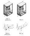
- FIG. 1shows a first assembly with connecting elements comprising assembled busbar sections (prior art),
- FIG. 2shows a connecting element for the assembly shown in FIG. 1 (prior art)
- FIG. 3shows a second assembly with integrally manufactured connecting elements
- FIG. 4shows a connecting element for the assembly shown in FIG. 2 [sic. 3 ].
- FIG. 1shows a first assembly with a plurality of connecting elements 1 in accordance with the prior art.
- One of these connecting elements 1is illustrated in detail in FIG. 2 .
- This connecting elementcomprises three sections 1 a , 1 b , 1 c of a busbar with an approximately rectangular cross section.
- Each of these sections 1 a , 1 b , 1 cis manufactured from a strip-like conductor piece which is bent one or more times.
- the bending radiican be, for example, of an order of magnitude of between the thickness and the width of the conductor pieces.
- Each of the sections 1 a , 1 b , 1 cis split into two or more straight subsections by the bends.
- the bending axes A 1 , A 2 , B 1 , C 1 , C 2 , C 3are all orthogonal to the longitudinal direction and are aligned in the direction of the broad side of the respective section.
- the influence of the deformation on parameters such as the total length of the conductor, for example,can be difficult to monitor. This applies in particular to copper conductors. Therefore, all deformations in the individual sections 1 a , 1 b , 1 c have the same form, preferably about axes which are aligned parallel to the broad side and orthogonal to the local longitudinal direction of the conductor piece.
- the lengths of the individual sections 1 a , 1 b , 1 care small in comparison with the total length of the connecting element 1 .
- two bores 3are formed at the two ends of each section 1 a , 1 b , 1 c .
- this hole patternchanges in accordance with EN43670.
- the longitudinal directions or the interconnected limbs of adjacent sections 1 a , 1 b or 1 b , 1 care aligned orthogonal to one another.
- FIG. 3shows a second assembly, which differs from the first assembly in terms of differently designed connecting elements 1 ′.
- This connecting elementis manufactured from a homogeneous or integral profile body with preferably an at least approximately rectangular cross section.
- the thickness of the profile bodyis greater than or equal to 2.5 mm and less than or equal to 120 mm.
- the width of the profile bodyis greater than or equal to 10 mm and less than or equal to 120 mm.
- the total length of the profile bodycan be up to 4 m or at most up to 6 m.
- the cross-sectional area of the profile bodyis greater than or equal to 25 mm 2 and the electrical conductivity thereof is greater than or equal to 25 m ( ⁇ mm 2 ).
- the originally straight profile bodyis deformed a plurality of times in different ways. It covers a plurality of straight or planar subregions which are aligned differently. Starting from the left-hand end, a 90° bend in the counter clockwise direction about a first axis A 1 ′ follows the first straight subsection.
- the first axis A 1 ′is aligned orthogonal to the longitudinal direction and in the width direction of the profile body.
- the inner bending radius or the bending radius of that side of the profile body which faces the bending axis A 1 ′is preferably between half and two times the profile body thickness.
- a region with a bend through 90° in the clockwise direction about a second axis A 2 ′is formed between the second and third straight subsections, with the second axis A 2 ′ being aligned parallel to the first axis A 1 ′.
- the profile bodyis deformed by vertical bending through 90° about a third axis A 3 ′ between the third and fourth straight subsection.
- the third axis A 3 ′is orthogonal to the first axis A 1 ′ and to the broad side of the profile body.
- the inner bending radius or the radius of the inner edge of the profile bodyis preferably between half and two times the profile body width.
- the profile bodytherefore has a plurality of different deformations such as bends, vertical bends or twisting distributed over its longitudinal extent.
- the number, type and arrangement of such deformationscan be fixed individually for each connecting element 1 ′.
- the deformation axes A 1 ′, A 2 ′, A 3 ′, A 4 ′, A 5 ′ A 6 ′can have any desired orientations in three-dimensional space in the region of the subregion of the profile body to be deformed, in particular in the direction of the length, the width or the depth of the profile body in the region to be deformed.
- the deformationscan be implemented in order from one end to the other end of the profile body by correspondingly designed bending apparatuses. Alternatively, any other desired sequence of deformations can also be predetermined.
- the parameters required for controlling the deformation apparatusesneed to be determined.
- a calculation apparatusdetermines the parameters required for producing the connecting element 1 ′. These include, for example, the total length of the profile body to be deformed, the number, type and arrangement of the required deformations and preferably the sequence of the deformations which are intended to be implemented successively.
- the different deformationscan be performed successively at correspondingly equipped deformation stations.
- the deformationsare matched to one another, preferably reference positions on the profile body are defined which can be taken into consideration by the deformation apparatuses.
- the deformation apparatusescan also be combined in a common deformation installation, wherein the workpiece can be moved automatically in a defined manner between the deformation apparatuses.
- connecting element 1 ′can optionally be sheathed completely or partially with an electrical insulating layer.
Landscapes
- Engineering & Computer Science (AREA)
- Power Engineering (AREA)
- Non-Insulated Conductors (AREA)
Abstract
Description
- 1,1′ Connecting element
- 1a,1b,1cBusbar sections
- 3 Bore
- 5 Screw
Claims (7)
Priority Applications (1)
| Application Number | Priority Date | Filing Date | Title |
|---|---|---|---|
| US13/668,576US9033721B2 (en) | 2012-11-05 | 2012-11-05 | Electrical connecting element |
Applications Claiming Priority (1)
| Application Number | Priority Date | Filing Date | Title |
|---|---|---|---|
| US13/668,576US9033721B2 (en) | 2012-11-05 | 2012-11-05 | Electrical connecting element |
Publications (2)
| Publication Number | Publication Date |
|---|---|
| US20140127955A1 US20140127955A1 (en) | 2014-05-08 |
| US9033721B2true US9033721B2 (en) | 2015-05-19 |
Family
ID=50622769
Family Applications (1)
| Application Number | Title | Priority Date | Filing Date |
|---|---|---|---|
| US13/668,576Active2033-04-23US9033721B2 (en) | 2012-11-05 | 2012-11-05 | Electrical connecting element |
Country Status (1)
| Country | Link |
|---|---|
| US (1) | US9033721B2 (en) |
Cited By (4)
| Publication number | Priority date | Publication date | Assignee | Title |
|---|---|---|---|---|
| US11056861B2 (en) | 2018-12-14 | 2021-07-06 | Eaton Intelligent Power Limited | Conductor for a power distribution system |
| US11791597B2 (en)* | 2021-02-05 | 2023-10-17 | Aptiv Technologies (2) S.À R.L. | Flexible electrical bus bar and method of manufacturing the same |
| US11870187B2 (en) | 2019-10-28 | 2024-01-09 | Eaton Intelligent Power Limited | Conductor assembly for a power distribution system |
| US11950390B2 (en) | 2019-10-28 | 2024-04-02 | Eaton Intelligent Power Limited | Conductor assembly for a power distribution system |
Citations (9)
| Publication number | Priority date | Publication date | Assignee | Title |
|---|---|---|---|---|
| KR0185284B1 (en) | 1996-04-04 | 1999-04-01 | 박병림 | A rotatory-stimulating apparatus for vestibular organ diagnosis |
| JP2006261100A (en) | 2005-02-17 | 2006-09-28 | Toyota Motor Corp | Bus bar, electrical circuit system |
| US20100012345A1 (en) | 2008-07-16 | 2010-01-21 | Gm Global Technology Operations, Inc. | Flexible electric bus bar in a small space |
| US20100319958A1 (en) | 2009-06-19 | 2010-12-23 | Square D Company | Insulation of busbars using insulating members having corrugated sections |
| WO2012008365A1 (en) | 2010-07-12 | 2012-01-19 | 矢崎総業株式会社 | Wire harness, method for transporting wire harness with devices, and method for connecting devices using wire harness |
| US8235732B2 (en)* | 2008-05-15 | 2012-08-07 | Johnson Controls—SAFT Advanced Power Solutions LLC | Battery system |
| DE102011013157A1 (en) | 2011-02-28 | 2012-08-30 | Power Economy M.E. Co. L.L.C. | Multiphase bus bar connection assembly has power switch that is rotated at specific angle along longitudinal axis of connection bus bars which are vertically arranged in connection region with main bar arrangement |
| US8337251B2 (en)* | 2006-08-31 | 2012-12-25 | Lisa Dräxlmaier GmbH | Tolerance-compensating current distribution board |
| US20130068495A1 (en)* | 2011-09-19 | 2013-03-21 | Rod Hadi | Flexible busbar |
- 2012
- 2012-11-05USUS13/668,576patent/US9033721B2/enactiveActive
Patent Citations (10)
| Publication number | Priority date | Publication date | Assignee | Title |
|---|---|---|---|---|
| KR0185284B1 (en) | 1996-04-04 | 1999-04-01 | 박병림 | A rotatory-stimulating apparatus for vestibular organ diagnosis |
| JP2006261100A (en) | 2005-02-17 | 2006-09-28 | Toyota Motor Corp | Bus bar, electrical circuit system |
| US8337251B2 (en)* | 2006-08-31 | 2012-12-25 | Lisa Dräxlmaier GmbH | Tolerance-compensating current distribution board |
| US8235732B2 (en)* | 2008-05-15 | 2012-08-07 | Johnson Controls—SAFT Advanced Power Solutions LLC | Battery system |
| US20100012345A1 (en) | 2008-07-16 | 2010-01-21 | Gm Global Technology Operations, Inc. | Flexible electric bus bar in a small space |
| DE102009031659A1 (en) | 2008-07-16 | 2010-01-21 | GM Global Technology Operations, Inc., Detroit | Flexible electric busbar with little space |
| US20100319958A1 (en) | 2009-06-19 | 2010-12-23 | Square D Company | Insulation of busbars using insulating members having corrugated sections |
| WO2012008365A1 (en) | 2010-07-12 | 2012-01-19 | 矢崎総業株式会社 | Wire harness, method for transporting wire harness with devices, and method for connecting devices using wire harness |
| DE102011013157A1 (en) | 2011-02-28 | 2012-08-30 | Power Economy M.E. Co. L.L.C. | Multiphase bus bar connection assembly has power switch that is rotated at specific angle along longitudinal axis of connection bus bars which are vertically arranged in connection region with main bar arrangement |
| US20130068495A1 (en)* | 2011-09-19 | 2013-03-21 | Rod Hadi | Flexible busbar |
Cited By (4)
| Publication number | Priority date | Publication date | Assignee | Title |
|---|---|---|---|---|
| US11056861B2 (en) | 2018-12-14 | 2021-07-06 | Eaton Intelligent Power Limited | Conductor for a power distribution system |
| US11870187B2 (en) | 2019-10-28 | 2024-01-09 | Eaton Intelligent Power Limited | Conductor assembly for a power distribution system |
| US11950390B2 (en) | 2019-10-28 | 2024-04-02 | Eaton Intelligent Power Limited | Conductor assembly for a power distribution system |
| US11791597B2 (en)* | 2021-02-05 | 2023-10-17 | Aptiv Technologies (2) S.À R.L. | Flexible electrical bus bar and method of manufacturing the same |
Also Published As
| Publication number | Publication date |
|---|---|
| US20140127955A1 (en) | 2014-05-08 |
Similar Documents
| Publication | Publication Date | Title |
|---|---|---|
| US8258404B2 (en) | Insulation of busbars using insulating members having corrugated sections | |
| CN103444000B (en) | Comprise the earthing bar assembly of mounting bracket and/or conductor block | |
| US9006571B2 (en) | Bus system connecting bus bars and a method of connecting bus bars | |
| US9033721B2 (en) | Electrical connecting element | |
| US8693169B2 (en) | Panelboard plug-on neutral bus and method of making same | |
| EP2670006B1 (en) | Plug-in type bus bar | |
| CN1184729C (en) | Conductor bar arrangement for electrical switchpanel | |
| US10290986B2 (en) | Systems and methods for connecting power distribution devices | |
| US10439341B2 (en) | Hybrid neutral plug on bar with distributed pitch | |
| US10931088B2 (en) | Stacked bus assembly with stepped profile | |
| KR101034418B1 (en) | Plate electric conductor | |
| US20210027966A1 (en) | Arrangement for connecting a circuit breaker to a conducting layer of a laminated busbar and switchgear comprising such an arrangement | |
| CN107851987B (en) | Apparatus for establishing multiphase electrical connections and equipment with corresponding apparatus | |
| NO20003660D0 (en) | Method for constructing a superconducting multiphase cable comprising N phases | |
| RU186328U1 (en) | POWER CABLE WITH HEATING ELEMENT | |
| US10522991B2 (en) | Compact busway for low and medium voltage | |
| DE102013017748B4 (en) | Electrical connecting element | |
| EP3736913B1 (en) | Low voltage power conductor and system | |
| EP3588712B1 (en) | A copper conductor | |
| US11855515B2 (en) | Multilayer neutral bus | |
| CN204732181U (en) | Power transmission bus bar | |
| CN204155615U (en) | A kind of extraction bus-bar of miniature circuit breaker | |
| WO2025096522A1 (en) | Compact switchboard systems and methods | |
| US9106059B2 (en) | Electric power distributor for connecting first and second multiphase aircraft generator power lines having single-phase cables | |
| KR20240139577A (en) | Power transferring busway and busway system having the same |
Legal Events
| Date | Code | Title | Description |
|---|---|---|---|
| AS | Assignment | Owner name:PROMET HOLDING AG, SWITZERLAND Free format text:CHANGE OF NAME;ASSIGNOR:PROMET AG;REEL/FRAME:029480/0706 Effective date:20121214 | |
| AS | Assignment | Owner name:PROMET HOLDING AG, SWITZERLAND Free format text:ASSIGNMENT OF ASSIGNORS INTEREST;ASSIGNORS:GRAF, ROGER;BENNETT, DEBRA M.;REEL/FRAME:029798/0025 Effective date:20121115 | |
| STCF | Information on status: patent grant | Free format text:PATENTED CASE | |
| CC | Certificate of correction | ||
| MAFP | Maintenance fee payment | Free format text:PAYMENT OF MAINTENANCE FEE, 4TH YR, SMALL ENTITY (ORIGINAL EVENT CODE: M2551); ENTITY STATUS OF PATENT OWNER: SMALL ENTITY Year of fee payment:4 | |
| MAFP | Maintenance fee payment | Free format text:PAYMENT OF MAINTENANCE FEE, 8TH YR, SMALL ENTITY (ORIGINAL EVENT CODE: M2552); ENTITY STATUS OF PATENT OWNER: SMALL ENTITY Year of fee payment:8 | |
| AS | Assignment | Owner name:PROMET AG, SWITZERLAND Free format text:MERGER;ASSIGNOR:PROMET HOLDING AG;REEL/FRAME:071624/0898 Effective date:20250619 |