US9024844B2 - Recognition of image on external display - Google Patents
Recognition of image on external displayDownload PDFInfo
- Publication number
- US9024844B2 US9024844B2US13/358,175US201213358175AUS9024844B2US 9024844 B2US9024844 B2US 9024844B2US 201213358175 AUS201213358175 AUS 201213358175AUS 9024844 B2US9024844 B2US 9024844B2
- Authority
- US
- United States
- Prior art keywords
- display screen
- user
- see
- external display
- computing device
- Prior art date
- Legal status (The legal status is an assumption and is not a legal conclusion. Google has not performed a legal analysis and makes no representation as to the accuracy of the status listed.)
- Active, expires
Links
Images


Classifications
- G—PHYSICS
- G06—COMPUTING OR CALCULATING; COUNTING
- G06F—ELECTRIC DIGITAL DATA PROCESSING
- G06F3/00—Input arrangements for transferring data to be processed into a form capable of being handled by the computer; Output arrangements for transferring data from processing unit to output unit, e.g. interface arrangements
- G06F3/01—Input arrangements or combined input and output arrangements for interaction between user and computer
- G06F3/011—Arrangements for interaction with the human body, e.g. for user immersion in virtual reality
- G06F3/013—Eye tracking input arrangements
- G06K9/00604—
- G—PHYSICS
- G06—COMPUTING OR CALCULATING; COUNTING
- G06V—IMAGE OR VIDEO RECOGNITION OR UNDERSTANDING
- G06V40/00—Recognition of biometric, human-related or animal-related patterns in image or video data
- G06V40/10—Human or animal bodies, e.g. vehicle occupants or pedestrians; Body parts, e.g. hands
- G06V40/18—Eye characteristics, e.g. of the iris
- G06V40/19—Sensors therefor
Definitions
- Augmented or mixed reality technologiesallow virtual imagery to be mixed with a user's actual view of the real world.
- a near-eye display systemcomprising a see-through display may be worn by a user to view the mixed imagery of virtual and real objects.
- Such a display systemoverlays virtual imagery in the user's field of view, and thereby allows the display of digital content configured to enhance real-world experiences.
- Embodimentsare disclosed herein that relate to the recognition via a see-through display system of an object displayed on an external display device at which a user of the see-through display system is gazing.
- a method of operating a see-through display systemthat includes a see-through display screen, a gaze detection subsystem configured to determine a direction of gaze of each eye of the user, and an outward facing image sensor configured to acquire images of a background scene relative to a user of the see-through display system.
- the methodcomprises acquiring an image of an external display screen located in the background scene via the outward facing image sensor, determining via the gaze detection subsystem a location on the external display screen at which the user is gazing, obtaining an identity of an object displayed on the external display screen at the location determined, and performing an action based upon the identity of the object.
- FIG. 1depicts a user of an embodiment of a see-through display system gazing at a display screen external to the see-through display system.
- FIG. 2shows a view from the perspective of the user of FIG. 1 when the user is gazing at a first virtual object displayed on the external display.
- FIG. 3shows a view from the perspective of the user of FIG. 1 when the user is gazing at a second virtual object displayed on the external display.
- FIG. 4shows a view from the perspective of the user of FIG. 1 after the user has made a gaze-based user input via the see-through display system to a device controlling the external display.
- FIG. 5shows a depiction of a user of an embodiment of a see-through display system viewing another example external display.
- FIG. 6shows a view from the perspective of the user of FIG. 5 when the user is gazing at a first actor displayed on the external display of FIG. 5 .
- FIG. 7shows an embodiment of a use environment for a see-through display system.
- FIG. 8shows an embodiment of a see-through display system.
- FIG. 9shows a block diagram of the embodiment of FIG. 9
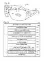
- FIG. 10shows a flow diagram depicting an embodiment of a method of operating a see-through display system.
- FIG. 11shows a block diagram depicting an embodiment of a computing device.
- a see-through display systemmay allow virtual imagery to be mixed with real-world background images, thereby enhancing real-world experiences.
- the ability to fully realize the potential of such interactionsmay be limited by the ability of a see-through display system to analyze and react to objects located in a wide range of real-world backgrounds, as well as the ability to determine particular objects in the real world background at which a user's gaze is directed.
- a see-through display systemsuch as a head-mounted display (HMD)
- HMDhead-mounted display
- gaze detection and outward-facing image sensor(s)to acquire and utilize information related to particular objects in the field of view of the user that are the subject of a user's current focus, such as objects shown on a display screen external to the see-through display device.
- Thismay allow the presentation of enhanced experiences via a see-through display system in virtually any use environment.
- contextual information related to an object of interest on an external display screenmay be obtained from a source other than a device controlling the external display screen.
- image recognition techniquesmay be used to determine an identity of the object on the external display screen at which the user is gazing so that contextually relevant information about the object may be obtained and displayed.
- the see-through display systemmay communicate with the device controlling the external display screen. This may allow a fusion of experiences, where a user may “select” a particular object on the external display screen by gazing at the particular object on a user interface displayed on the external display screen.
- FIGS. 1 and 2show an example use environment in which a user of an embodiment of a see-through display system 100 retrieves via the see-through display system information relevant to an object displayed on an example external display screen 102 , shown as being incorporated into a mobile device 104 .
- gaze lines 200 , 202are determined to lead from the eyes of the user to an email user interface tile 204 .
- the see-through display system 100retrieves and displays a list 206 of messages currently in the inbox of an email account linked to the user's mobile device 104 . The user may then be able to open a selected message by gazing at the selected message in the inbox displayed on the see-through display system 100 .
- the see-through display system 100may receive the inbox information via communication with the mobile device 104 , or via communication with another device, such as a network-accessible email service.
- the usermay be able to retrieve contextual information regarding other user interface elements displayed on the external display screen by gazing at the other user interface elements. For example, referring to FIG. 3 , the user has ceased gazing at the email user interface tile 204 , and is instead gazing at a weather user interface tile 208 displayed on the external display screen 102 . In response, the see-through display system 100 retrieves and displays a current weather report 210 .
- the see-through display system 100may communicate with the device that controls the external display, e.g. the mobile device 104 in the embodiment of FIG. 1 .
- the see-through display system 100may also act as a user input device that allows a user to “select” a particular user interface control displayed on the external display screen.
- FIG. 4shows an example of such an interaction in the context of the user gazing at the weather tile of FIG. 3 .
- the head-mounted display system 100may send a user input command to the mobile device 104 selecting the weather tile 208 , thereby resulting in the display of weather information on the external display screen 102 of the mobile device 104 .
- FIG. 4also shows the display of additional weather-related user interface items 300 on the see-through display.
- a usermay interact with the additional weather-related user interface items 300 via gaze, and selection of one of the additional weather-related user interface items may result in the display of relevant information by the mobile device 104 , by the see-through display system 100 , or by a combination of these devices. It will be understood that such additional user interface items also may be displayed on the mobile device 104 . It will further be understood that such additional user interface items may be displayed on both the mobile device 104 and the see-through display system 100 . In this manner, the see-through display system 100 and the mobile device 104 may cooperate to present an integrated multi-display user interface experience.
- FIGS. 1-4illustrate a use environment in which a user gazes at an external display screen incorporated into and controlled by a mobile device.
- a usermay view any other suitable external display device via a see-through display system according to the present disclosure.
- FIGS. 5-6illustrate another example use environment in which a user is watching via the see-through display system 100 an external display screen in the form of a television 500 and gazing at a particular actress 502 .
- the see-through display system 100may determine that the user is gazing at the actress by gaze and image analysis, and in response obtain and display information 504 regarding the actress 502 .
- Similar methodsmay be used in conjunction with displays in storefronts, sports stadiums, and the like that may be controlled by third parties.
- a user gazing at an electronic display in a storefrontmay receive via a see-through display system information on an object shown on the display.
- the see-through display system 100displays a menu of items of information about the actress that a user may browse, for example, via gaze control, voice control, or in any other suitable manner.
- the see-through display system 100may display any other suitable information.
- a usermay control the television 500 via gaze commands. For example, a user may change channels, interact with a video game system or a digital video recorder (e.g. to bring up a menu of recorded items in which the actor at which the user is gazing appears), and perform other such control actions, by gazing at corresponding objects on the television screen.
- gaze commandsmay be used to zoom, shift, and/or otherwise change an image to highlight a particular object of interest in a current scene.
- optically readable tagsmay be embedded in an image displayed on an external display screen (e.g. within video content) such that the tags are associated with particular objects on the screen.
- the tagsmay be used to obtain information about the object without having to perform image analysis to identify the object.
- a determination of a user's intent to interact with an object at which the user is gazingmay be made before information regarding the object is obtained and displayed.
- the user's intentmay be determined in any suitable manner. For example, an intent of the user to interact with the displayed object may be determined from sensor input indicating that the user's gaze is directed at the displayed object for a threshold amount of time. Such an intent may be determined from any suitable gaze duration, including but not limited to durations of 500 msec, 1 second, or 5 seconds.
- the user's intent to interactmay be determined via voice recognition analysis of audio input received from the user, by outward facing sensor input capturing a hand and/or arm gesture of the user, by inward facing sensor input capturing an eye gesture of a user, by motion data capturing a head (or body) gesture of the user, or via any other suitable input or combination of inputs.
- FIG. 7shows a block diagram of an example use environment 700 for a see-through display system 702 .
- Use environment 700includes a local use environment 704 comprising devices at the user's immediate locale, and a network environment 706 accessible by the see-through display system 702 via a network 708 .
- the see-through display system 702may comprise any suitable type of device, including but not limited to the HMD shown in FIGS. 1-6 .
- the local use environment 704comprises the see-through display system 702 , and an external display screen 710 controlled by a computing device 712 configured to provide output to the external display screen 710 .
- the external display screen 710 and the computing device 712may be separate devices or integrated into a same device, and may represent any suitable type of display and computing device.
- Non-limiting examples of such display screensinclude screens on mobile communications devices (e.g. smart phones), portable media players, televisions (e.g. two-dimensional or three-dimensional high-definition televisions), and computer monitors, as well as movie theater screens, electronic billboards, and other such large-format display screens (e.g. at sports venues).
- the see-through display system 702is configured to project a determined gaze line 713 from each eye of a user onto the external display screen 710 to determine a location on the external display screen at which the user is currently gazing.
- the see-through display system 702may utilize any suitable mechanism for determining such gaze lines, including but not limited to inward-facing image sensors configured to track eye motion, outward facing image sensors configured to acquire images of a field of view of the user, and/or inertial motion sensors configured to provide data for tracking user movements.
- Image data acquired by the outward-facing image sensorsmay be used to obtain an identification of an object on the external display screen 710 at which the user is gazing.
- the computing device 712may provide information to the see-through display system 702 identifying objects displayed on the external display screen 710 .
- the see-through display system 702may then compare an image of the object intersected by the gaze lines 713 to the information provided by the computing device 712 to identify the particular object at which the user is gazing.
- communication between the see-through display system 702 and the computing device 712 that controls the external display screen 710may be wired or wireless.
- the see-through display systemmay send to the computing device 712 image data of the object at the location at which the user is gazing for identification of the image by the computing device 712 .
- image data representing a portion of the external display screen 710 at which the user is gazingmay be sent to a network-accessible object identification service 714 for identification.
- the object identification service 714may compare the image data to image data in an identity information store 716 to identify the object.
- the object identification servicemay then return the identity of the object to the see-through display system 702 .
- other informationsuch as location information, also may be sent to the object identification service to facilitate the identification of the object.
- the depicted use environment 700further comprises a plurality of contextual information services, depicted as contextual information service 1 718 and contextual information service n 720 .
- the contextual information services 718 , 720are configured to receive queries from devices such as the see-through display system 702 , and to provide information relevant to the query provided.
- the contextual information services 718 , 720may take any suitable form, such as publicly accessible and/or restricted access web sites.
- Each contextual information serviceis configured to access one or more information stores, depicted as local information stores 722 , 724 and network-accessible information store 726 .
- a contextual information servicemay take the form of a search engine that searches across a network, or of a proprietary database service.
- the see-through display system 702may be configured to access different contextual information services depending upon the identification of the object at which the user is gazing. For example, where the user is gazing at an email user interface control, the see-through display system 702 may access the user's email account via an email service. Likewise, where the user is gazing at a particular actor displayed on a television, the see-through display system 702 may access a media database that stores information related to television and movie actors. In this manner, the see-through display system 702 operating in use environment 700 may acquire information for display that is contextually relevant to a particular object on an external display screen at which a user is gazing.
- the see-through display system 702may take any suitable form.
- a see-through display systemmay comprise a pair of glasses in which the lenses act as see-through display screens.
- FIG. 8shows an embodiment of such a see-through display system 800
- FIG. 9shows a block diagram of the see-through display system 800 .
- the see-through display system 800comprises one or more lenses 802 that form a part of a see-through display subsystem 804 , such that images may be projected onto the lenses 802 , or produced by image-producing elements (e.g. see-through OLED displays) located within the lenses 802 .
- image-producing elementse.g. see-through OLED displays
- the see-through display system 800further comprises one or more outward facing image sensors 806 configured to acquire images of a background scene being viewed by a user, and may include one or more microphones 808 configured to detect sounds, such as voice commands from a user.
- the outward facing image sensors 806may include one or more depth sensors and/or one or more two-dimensional image sensors.
- the see-through display system 800further comprises a gaze detection subsystem 810 configured to detect a direction of gaze of each eye of a user, as described above.
- the gaze detection subsystem 810may be configured to determine gaze directions of each of a user's eyes in any suitable manner.
- the gaze detection subsystem 810comprises one or more glint sources 812 , such as infrared light sources, configured to cause a glint of light to reflect from each eyeball of a user, and one or more image sensors 814 configured to capture an image of each eyeball of the user. Changes in the glints from the user's eyeballs as determined from image data gathered via image sensor(s) 814 may be used to determine a direction of gaze.
- a location at which gaze lines projected from the user's eyes intersect the external displaymay be used to determine an object at which the user is gazing (e.g. a virtual object displayed on an external display).
- the gaze detection subsystem 810may have any suitable number and arrangement of light sources and image sensors. In one non-limiting example embodiment, four glint sources and one image sensor are used for each eye.
- the see-through display system 800may further comprise additional sensors.
- see-through display system 800may comprise a global positioning (GPS) subsystem 816 to allow a location of the see-through display system 800 to be determined.
- GPSglobal positioning
- Information regarding the user's locationmay then be used, for example, to help determine the identity of an object on an external display at which the user is gazing.
- location informationmay be used to determine that a user is in a particular movie theater. This information may then be used to help identify contextual information, for example, by identifying a movie playing at that particular time in that particular theater and actors starring in that particular movie.
- the see-through display system 800may comprise a clock (not shown) or otherwise be configured to receive a remotely generated time signal, to provide additional information that may be used to determine the context of a user's current environment. For example, information regarding the time that the user is in the particular movie theater may allow the identity of a movie being watched to be determined. This information may then be used by the see-through display system 800 to retrieve and present information relevant to objects in the movie being watched.
- the see-through display system 800further may include one or more motion sensors 818 to detect movements of a user's head when the user is wearing the see-through display system 800 .
- Motion datamay be used, potentially along with eye-tracking glint data and outward-facing image data, for gaze detection, as well as for image stabilization to help correct for blur in images from the outward-facing image sensor(s) 806 .
- the use of motion datamay allow changes in gaze location to be tracked even if image data from the outward-facing image sensor(s) 806 cannot be resolved.
- the motion sensors 818may be employed as user input devices, such that a user may interact with see-through display system 800 via gestures of the eye, neck and/or head, as well as via verbal commands. It will be understood that sensors illustrated in FIGS. 8 and 9 are shown for the purpose of example and are not intended to be limiting in any manner, as any other suitable sensors and/or combination of sensors may be utilized.
- the see-through display system 800further comprises a controller 820 having a logic subsystem 822 and a data holding subsystem 824 in communication with the sensors, the gaze detection subsystem 810 , and the see-through display subsystem 804 .
- the data holding subsystem 824comprises instructions stored thereon that are executable by logic subsystem 822 , for example, to receive and interpret inputs from the sensors, to determine an object at which the user is gazing, to send information (e.g. image data) to an external computing device for identification of the object via a communications subsystem 826 , and to receive and potentially present contextual information regarding the object via the see-through display subsystem 804 , and/or via one or more speakers 828 .
- data holding subsystem 824also may store information regarding other objects displayed on the external display screen (e.g. a list of user interface controls locations and identities/functions).
- FIG. 10shows an embodiment of a method 1000 of operating a see-through display system according to the present disclosure.
- Method 1000comprises, at 1002 , acquiring one or more images of an external display screen located in background scene. This may comprise, for example, receiving two-dimensional and/or three-dimensional still or video image data from one or more outward-facing image sensors on a see-through display device, and locating the external display screen in the image data.
- Method 1000next comprises, at 1004 , determining a location on external display screen at which user is gazing.
- Thismay comprise, for example, receiving image data from one or more inward-facing image sensors, and analyzing the image data to determine the position of the user's eye based upon location of glints reflected from the eye of the user. This may allow the detection of a direction of gaze of each eye of the user, as indicated at 1006 . Gaze lines may then be projected through and beyond the see-through display device to the external display screen, as indicated at 1008 .
- determining the location on the external display at which the user is gazingmay further comprise analyzing motion data from one or more inertial motion sensors to track movement of the user's gaze.
- Method 1000next comprises, at 1010 , obtaining an identity of object displayed on the external display screen based upon a location at which the determined gaze lines intersect the external display screen.
- Thismay comprise various processes.
- the see-through display devicemay not be in communication with the computing device that controls the external display screen.
- method 1000may comprise, at 1012 , sending information regarding the object to a remote computing device, such as a network accessible object identity service, that is not in control of the external display screen.
- a remote computing devicesuch as a network accessible object identity service
- Any suitable informationmay be sent to the remote computing device. Examples include, but are not limited to, image information 1014 (e.g. image data representing the object), and/or location information (e.g. GPS data) that may facilitate the matching of image information 1016 to object image data by the remote computing device.
- identification informationis received from the remote computing system at 1018 .
- the see-through display devicemay be in communication with the computing device that controls the external display screen.
- method 1000may comprise, at 1020 , sending information regarding the object to a remote computing device in control of the external display screen, such as a mobile device, television system, or other suitable computing device. Any suitable information may be sent, including but not limited to image information 1024 and gaze location information 1026 that specifies the location of the gaze on the screen.
- image information 1024and gaze location information 1026 that specifies the location of the gaze on the screen.
- information regarding the identities of one or more objects displayed on the external display screenis received from the computing system at 1027 .
- information regarding multiple objects displayed on the external display screenmay be received from the computing device in control of the external display screen.
- the information sent to the computing device that controls the external display screenmay comprise a specific user interface command, rather than (or in addition to) image or location information.
- method 1000next comprises, at 1028 , performing an action based upon the identity of the object.
- the see-through display devicemay perform any suitable action based upon the identity of the object.
- the see-through display devicemay request contextual information from a network-based service.
- the see-through display devicemay request information about the actor after obtaining the identity of the actor.
- the contextual informationthen is received from the network-based service and displayed at 1032 .
- the see-through display devicemay send a user interface command to a computing device that is in control of the external display screen, as indicated at 1034 and described above.
- a see-through display devicemay track changes in gaze location, as indicated at 1036 . This may help to ensure that the displayed contextual information remains when the user's gaze shifts to different displayed objects. Such changes may be tracked via image data 1038 , by inertial motion data 1040 , and/or in any other suitable manner.
- method 1000comprises, at 1042 , performing an action based upon the change in gaze location. For example, if the change in gaze location moved from one tile on a mobile device user interface to another tile, the action may comprise obtaining an identification of the new tile, obtaining contextual information based upon the identification of the new tile, and displaying this additional information via the see-through display system. It will be understood that this specific example is described for the purpose of illustration, and is not intended to be limiting in any manner.
- outward facing image data acquired by a see-through display deviceis used to project gaze lines through the see-through display device onto the external display screen.
- gaze line projectionmay be performed by a combination of a see-through display device worn or carried by a user, and an external image capture and analysis system comprising a depth sensor.
- the external image capture and analysis systemmay determine gaze lines based upon a depth map of the use environment to determine a location of the external display screen at which the user is gazing. The location may then be matched to a displayed object either by communication between the external image capture and analysis system (e.g. a video game system or other entertainment system) and the computing device in control of the external display screen (e.g. a mobile device).
- Thismay be communicated to the see-through display device for the retrieval of contextual information regarding the object by the see-through display device.
- motion sensors in the see-through display deviceand potentially the external display device, e.g. a mobile device
- the above described methods and processesmay be tied to a computing system including one or more computers.
- computing systemsinclude, but are not limited to, see-through display devices such as HMDs, computing devices in control of display screens external to such see-through display devices (e.g. mobile devices, television systems, etc.), and computer systems implementing network-accessible services.
- see-through display devicessuch as HMDs
- computing devices in control of display screens external to such see-through display devicese.g. mobile devices, television systems, etc.
- computer systems implementing network-accessible servicese.g. mobile devices, television systems, etc.
- the methods and processes described hereinmay be implemented as a computer application, computer service, computer API, computer library, and/or other computer program product.
- FIG. 11schematically shows a nonlimiting computing system 1100 that may perform one or more of the above described methods and processes.
- Computing system 1100is shown in simplified form. It is to be understood that virtually any computer architecture may be used without departing from the scope of this disclosure.
- computing system 1100may take the form of a mainframe computer, server computer, desktop computer, laptop computer, tablet computer, home entertainment computer, network computing device, mobile computing device such as a smart phone or media player, mobile communication device, gaming device, see-through display system, etc.
- Computing system 1100includes a logic subsystem 1102 and a data holding subsystem 1104 .
- Computing system 1100may optionally include a display subsystem 1106 , communication subsystem 1108 , and/or other components not shown in FIG. 11 .
- Computing system 1100may also optionally include user input devices such as keyboards, mice, game controllers, cameras, microphones, and/or touch screens, for example, as well as the other input devices such as those described above for the see-through display system 800 .
- Logic subsystem 1102may include one or more physical devices configured to execute one or more instructions.
- logic subsystem 1102may be configured to execute one or more instructions that are part of one or more applications, services, programs, routines, libraries, objects, components, data structures, or other logical constructs. Such instructions may be implemented to perform a task, implement a data type, transform the state of one or more devices, or otherwise arrive at a desired result.
- Logic subsystem 1102may include one or more processors that are configured to execute software instructions. Additionally or alternatively, logic subsystem 1102 may include one or more hardware or firmware logic machines configured to execute hardware or firmware instructions. Processors of logic subsystem 1102 may be single core or multicore, and the programs executed thereon may be configured for parallel or distributed processing. Logic subsystem 1102 may optionally include individual components that are distributed throughout two or more devices, which may be remotely located and/or configured for coordinated processing. One or more aspects of logic subsystem 1102 may be virtualized and executed by remotely accessible networked computing devices configured in a cloud computing configuration.
- Data holding subsystem 1104may include one or more physical, non-transitory, devices configured to hold data and/or instructions executable by logic subsystem 1102 to implement the herein described methods and processes. When such methods and processes are implemented, the state of data holding subsystem 1104 may be transformed (e.g., to hold different data).
- Data holding subsystem 1104may include removable media and/or built-in devices.
- Data holding subsystem 1104may include optical memory devices (e.g., CD, DVD, HD-DVD, Blu-Ray Disc, etc.), semiconductor memory devices (e.g., RAM, EPROM, EEPROM, etc.) and/or magnetic memory devices (e.g., hard disk drive, floppy disk drive, tape drive, MRAM, etc.), among others.
- Data holding subsystem 1104may include devices with one or more of the following characteristics: volatile, nonvolatile, dynamic, static, read/write, read-only, random access, sequential access, location addressable, file addressable, and content addressable.
- logic subsystem 1102 and data holding subsystem 1104may be integrated into one or more common devices, such as an application specific integrated circuit or a system on a chip.
- FIG. 11also shows an aspect of the data holding subsystem in the form of removable computer-readable storage media 1110 , which may be used to store and/or transfer data and/or instructions executable to implement the herein described methods and processes.
- Removable computer-readable storage media 1110may take the form of CDs, DVDs, HD-DVDs, Blu-Ray Discs, EEPROMs, and/or floppy disks, among others.
- data holding subsystem 1104includes one or more physical, non-transitory devices.
- aspects of the instructions described hereinmay be propagated in a transitory fashion by a pure signal (e.g., an electromagnetic signal, an optical signal, etc.) that is not held by a physical device for at least a finite duration.
- a pure signale.g., an electromagnetic signal, an optical signal, etc.
- data and/or other forms of information pertaining to the present disclosuremay be propagated by a pure signal.
- a “service”, as used herein,may be an application program executable across multiple user sessions and available to one or more system components, programs, and/or other services.
- a servicemay run on a server responsive to a request from a client.
- Display subsystem 1106may be used to present a visual representation of data held by data holding subsystem 1104 . As the herein described methods and processes change the data held by the data holding subsystem, and thus transform the state of the data holding subsystem, the state of display subsystem 1106 may likewise be transformed to visually represent changes in the underlying data.
- Display subsystem 1106may include one or more display devices utilizing virtually any type of technology. Such display devices may be combined with logic subsystem 1102 and/or data holding subsystem 1104 in a shared enclosure, or such display devices may be peripheral display devices.
- Communication subsystem 1108may be configured to communicatively couple computing system 1100 with one or more other computing devices.
- Communication subsystem 1108may include wired and/or wireless communication devices compatible with one or more different communication protocols.
- the communication subsystemmay be configured for communication via a wireless telephone network, a wireless local area network, a wired local area network, a wireless wide area network, a wired wide area network, etc.
- the communication subsystemmay allow computing system 1100 to send and/or receive messages to and/or from other devices via a network such as the Internet.
Landscapes
- Engineering & Computer Science (AREA)
- Theoretical Computer Science (AREA)
- General Engineering & Computer Science (AREA)
- Human Computer Interaction (AREA)
- Physics & Mathematics (AREA)
- General Physics & Mathematics (AREA)
- Health & Medical Sciences (AREA)
- General Health & Medical Sciences (AREA)
- Ophthalmology & Optometry (AREA)
- Multimedia (AREA)
- User Interface Of Digital Computer (AREA)
- Controls And Circuits For Display Device (AREA)
Abstract
Description
Claims (20)
Priority Applications (2)
| Application Number | Priority Date | Filing Date | Title |
|---|---|---|---|
| US13/358,175US9024844B2 (en) | 2012-01-25 | 2012-01-25 | Recognition of image on external display |
| PCT/US2013/022769WO2013112603A1 (en) | 2012-01-25 | 2013-01-23 | Recognition of image on external display |
Applications Claiming Priority (1)
| Application Number | Priority Date | Filing Date | Title |
|---|---|---|---|
| US13/358,175US9024844B2 (en) | 2012-01-25 | 2012-01-25 | Recognition of image on external display |
Publications (2)
| Publication Number | Publication Date |
|---|---|
| US20130187835A1 US20130187835A1 (en) | 2013-07-25 |
| US9024844B2true US9024844B2 (en) | 2015-05-05 |
Family
ID=48796804
Family Applications (1)
| Application Number | Title | Priority Date | Filing Date |
|---|---|---|---|
| US13/358,175Active2033-09-27US9024844B2 (en) | 2012-01-25 | 2012-01-25 | Recognition of image on external display |
Country Status (2)
| Country | Link |
|---|---|
| US (1) | US9024844B2 (en) |
| WO (1) | WO2013112603A1 (en) |
Cited By (5)
| Publication number | Priority date | Publication date | Assignee | Title |
|---|---|---|---|---|
| US20150162000A1 (en)* | 2013-12-10 | 2015-06-11 | Harman International Industries, Incorporated | Context aware, proactive digital assistant |
| US20160212401A9 (en)* | 2013-01-24 | 2016-07-21 | Yuchen Zhou | Method and apparatus to produce re-focusable vision with detecting re-focusing event from human eye |
| US10191281B2 (en)* | 2011-12-16 | 2019-01-29 | Sony Corporation | Head-mounted display for visually recognizing input |
| US11327558B2 (en)* | 2020-04-02 | 2022-05-10 | Microsoft Technology Licensing, Llc | Physical gesture based data manipulation within a virtual scene for investigating a security incident |
| US12333803B2 (en) | 2022-01-10 | 2025-06-17 | Samsung Electronics Co., Ltd. | Electronic device for displaying AR object and method thereof |
Families Citing this family (94)
| Publication number | Priority date | Publication date | Assignee | Title |
|---|---|---|---|---|
| US8427424B2 (en) | 2008-09-30 | 2013-04-23 | Microsoft Corporation | Using physical objects in conjunction with an interactive surface |
| US8730309B2 (en) | 2010-02-23 | 2014-05-20 | Microsoft Corporation | Projectors and depth cameras for deviceless augmented reality and interaction |
| US11705232B2 (en)* | 2021-02-11 | 2023-07-18 | Nuance Communications, Inc. | Communication system and method |
| US9329469B2 (en) | 2011-02-17 | 2016-05-03 | Microsoft Technology Licensing, Llc | Providing an interactive experience using a 3D depth camera and a 3D projector |
| US9480907B2 (en) | 2011-03-02 | 2016-11-01 | Microsoft Technology Licensing, Llc | Immersive display with peripheral illusions |
| US9597587B2 (en) | 2011-06-08 | 2017-03-21 | Microsoft Technology Licensing, Llc | Locational node device |
| WO2013117999A1 (en)* | 2012-02-06 | 2013-08-15 | Sony Ericsson Mobile Communications Ab | Gaze tracking with projector |
| KR101638812B1 (en)* | 2012-04-23 | 2016-07-12 | 인텔 코포레이션 | System, method, and computer program product for using eye movement tracking for retrieval of observed information and of related specific context |
| KR101343748B1 (en)* | 2012-04-23 | 2014-01-08 | 주식회사 브이터치 | Transparent display virtual touch apparatus without pointer |
| EP2847648A4 (en)* | 2012-05-09 | 2016-03-02 | Intel Corp | Eye tracking based selective accentuation of portions of a display |
| US9823742B2 (en) | 2012-05-18 | 2017-11-21 | Microsoft Technology Licensing, Llc | Interaction and management of devices using gaze detection |
| CN103970258B (en)* | 2013-01-28 | 2018-08-07 | 联想(北京)有限公司 | Wearable electronic equipment and display methods |
| US9791921B2 (en)* | 2013-02-19 | 2017-10-17 | Microsoft Technology Licensing, Llc | Context-aware augmented reality object commands |
| US9898081B2 (en)* | 2013-03-04 | 2018-02-20 | Tobii Ab | Gaze and saccade based graphical manipulation |
| US11714487B2 (en) | 2013-03-04 | 2023-08-01 | Tobii Ab | Gaze and smooth pursuit based continuous foveal adjustment |
| US10895909B2 (en) | 2013-03-04 | 2021-01-19 | Tobii Ab | Gaze and saccade based graphical manipulation |
| US10895908B2 (en)* | 2013-03-04 | 2021-01-19 | Tobii Ab | Targeting saccade landing prediction using visual history |
| US9911361B2 (en) | 2013-03-10 | 2018-03-06 | OrCam Technologies, Ltd. | Apparatus and method for analyzing images |
| US9436887B2 (en)* | 2013-03-15 | 2016-09-06 | OrCam Technologies, Ltd. | Apparatus and method for automatic action selection based on image context |
| KR20140133362A (en)* | 2013-05-10 | 2014-11-19 | 삼성전자주식회사 | display apparatus and user interface screen providing method thereof |
| AU2014274232B2 (en)* | 2013-05-28 | 2020-03-26 | Pixium Vision | Smart prosthesis for facilitating artificial vision using scene abstraction |
| US20140354533A1 (en)* | 2013-06-03 | 2014-12-04 | Shivkumar Swaminathan | Tagging using eye gaze detection |
| US10073518B2 (en)* | 2013-08-19 | 2018-09-11 | Qualcomm Incorporated | Automatic calibration of eye tracking for optical see-through head mounted display |
| US10914951B2 (en)* | 2013-08-19 | 2021-02-09 | Qualcomm Incorporated | Visual, audible, and/or haptic feedback for optical see-through head mounted display with user interaction tracking |
| US10430150B2 (en) | 2013-08-23 | 2019-10-01 | Tobii Ab | Systems and methods for changing behavior of computer program elements based on gaze input |
| JP2015046089A (en)* | 2013-08-29 | 2015-03-12 | ソニー株式会社 | Information processor and information processing method |
| KR102156799B1 (en)* | 2013-09-03 | 2020-09-21 | 삼성전자 주식회사 | Method and apparatus for controlling screen on mobile device |
| JP6209906B2 (en)* | 2013-09-05 | 2017-10-11 | セイコーエプソン株式会社 | Head-mounted display device, method for controlling head-mounted display device, and image display system |
| EP3055754B1 (en)* | 2013-10-11 | 2023-08-02 | InterDigital Patent Holdings, Inc. | Gaze-driven augmented reality |
| FR3011952B1 (en)* | 2013-10-14 | 2017-01-27 | Suricog | METHOD OF INTERACTION BY LOOK AND ASSOCIATED DEVICE |
| EP3525033B1 (en)* | 2013-12-27 | 2021-07-21 | INTEL Corporation | Device, method, and system of providing extended display with head mounted display |
| US9442631B1 (en) | 2014-01-27 | 2016-09-13 | Google Inc. | Methods and systems for hands-free browsing in a wearable computing device |
| KR102182162B1 (en)* | 2014-02-20 | 2020-11-24 | 엘지전자 주식회사 | Head mounted display and method for controlling the same |
| KR102182161B1 (en)* | 2014-02-20 | 2020-11-24 | 엘지전자 주식회사 | Head mounted display and method for controlling the same |
| US9412363B2 (en) | 2014-03-03 | 2016-08-09 | Microsoft Technology Licensing, Llc | Model based approach for on-screen item selection and disambiguation |
| WO2015142228A1 (en)* | 2014-03-18 | 2015-09-24 | Telefonaktiebolaget L M Ericsson (Publ) | Controlling a target device |
| KR102279681B1 (en)* | 2014-05-26 | 2021-07-20 | 에스케이플래닛 주식회사 | Apparatus and method for providing advertisement using pupil recognition |
| US20150362990A1 (en)* | 2014-06-11 | 2015-12-17 | Lenovo (Singapore) Pte. Ltd. | Displaying a user input modality |
| KR20160001465A (en)* | 2014-06-27 | 2016-01-06 | 엘지전자 주식회사 | Glass type terminal and control method thereof |
| WO2016017945A1 (en)* | 2014-07-29 | 2016-02-04 | Samsung Electronics Co., Ltd. | Mobile device and method of pairing the same with electronic device |
| JP5989725B2 (en)* | 2014-08-29 | 2016-09-07 | 京セラドキュメントソリューションズ株式会社 | Electronic device and information display program |
| CN104267812B (en)* | 2014-09-22 | 2017-08-29 | 联想(北京)有限公司 | A kind of information processing method and electronic equipment |
| US10317992B2 (en) | 2014-09-25 | 2019-06-11 | Microsoft Technology Licensing, Llc | Eye gaze for spoken language understanding in multi-modal conversational interactions |
| JP2016082462A (en)* | 2014-10-20 | 2016-05-16 | セイコーエプソン株式会社 | Head-mounted display device, control method therefor, and computer program |
| KR102265086B1 (en) | 2014-11-07 | 2021-06-15 | 삼성전자 주식회사 | Virtual Environment for sharing of Information |
| US9933985B2 (en)* | 2015-01-20 | 2018-04-03 | Qualcomm Incorporated | Systems and methods for managing content presentation involving a head mounted display and a presentation device |
| US20170330036A1 (en)* | 2015-01-29 | 2017-11-16 | Aurasma Limited | Provide augmented reality content |
| WO2016136837A1 (en)* | 2015-02-25 | 2016-09-01 | 京セラ株式会社 | Wearable device, control method and control program |
| JP2016170528A (en)* | 2015-03-11 | 2016-09-23 | 株式会社リコー | Head mounted display and method for connecting with external device at head mounted display |
| US10055888B2 (en) | 2015-04-28 | 2018-08-21 | Microsoft Technology Licensing, Llc | Producing and consuming metadata within multi-dimensional data |
| EP3096517A1 (en) | 2015-05-22 | 2016-11-23 | TP Vision Holding B.V. | Wearable smart glasses |
| EP3109733B1 (en)* | 2015-06-22 | 2020-07-22 | Nokia Technologies Oy | Content delivery |
| US10275868B2 (en)* | 2015-07-01 | 2019-04-30 | Mediatek Inc. | Object analyzing method and object analyzing system |
| US10380966B2 (en) | 2015-08-31 | 2019-08-13 | International Business Machines Corporation | Power and processor management for a personal imaging system |
| US10545714B2 (en)* | 2015-09-04 | 2020-01-28 | Samsung Electronics Co., Ltd. | Dual screen head mounted display |
| JP6684559B2 (en)* | 2015-09-16 | 2020-04-22 | 株式会社バンダイナムコエンターテインメント | Program and image generation device |
| JP6598617B2 (en)* | 2015-09-17 | 2019-10-30 | キヤノン株式会社 | Information processing apparatus, information processing method, and program |
| WO2017048165A1 (en)* | 2015-09-17 | 2017-03-23 | Telefonaktiebolaget Lm Ericsson (Publ) | Communication device, first radio node, second radio node, and methods therein, for determining whether to allow a first vehicle to overtake a vehicle platoon |
| US9886958B2 (en) | 2015-12-11 | 2018-02-06 | Microsoft Technology Licensing, Llc | Language and domain independent model based approach for on-screen item selection |
| US20180366089A1 (en)* | 2015-12-18 | 2018-12-20 | Maxell, Ltd. | Head mounted display cooperative display system, system including dispay apparatus and head mounted display, and display apparatus thereof |
| US10120635B2 (en)* | 2016-03-09 | 2018-11-06 | Samsung Electronics Co., Ltd. | Configuration and operation of display devices including device management |
| ES2964705T3 (en) | 2016-05-06 | 2024-04-09 | Univ Leland Stanford Junior | Mobile and portable video capture and feedback platforms for the therapy of mental disorders |
| CN106445098A (en)* | 2016-07-29 | 2017-02-22 | 北京小米移动软件有限公司 | Control method and control apparatus used for head-mounted device, and mobile device |
| US20180077430A1 (en) | 2016-09-09 | 2018-03-15 | Barrie Hansen | Cloned Video Streaming |
| WO2018082767A1 (en) | 2016-11-02 | 2018-05-11 | Telefonaktiebolaget Lm Ericsson (Publ) | Controlling display of content using an external display device |
| JP6820469B2 (en)* | 2016-12-14 | 2021-01-27 | キヤノンマーケティングジャパン株式会社 | Information processing equipment, information processing system, its control method and program |
| US10393312B2 (en) | 2016-12-23 | 2019-08-27 | Realwear, Inc. | Articulating components for a head-mounted display |
| US10437070B2 (en) | 2016-12-23 | 2019-10-08 | Realwear, Inc. | Interchangeable optics for a head-mounted display |
| US11099716B2 (en) | 2016-12-23 | 2021-08-24 | Realwear, Inc. | Context based content navigation for wearable display |
| US11507216B2 (en) | 2016-12-23 | 2022-11-22 | Realwear, Inc. | Customizing user interfaces of binary applications |
| US10620910B2 (en)* | 2016-12-23 | 2020-04-14 | Realwear, Inc. | Hands-free navigation of touch-based operating systems |
| US10936872B2 (en) | 2016-12-23 | 2021-03-02 | Realwear, Inc. | Hands-free contextually aware object interaction for wearable display |
| US11036289B2 (en)* | 2016-12-31 | 2021-06-15 | Facebook, Inc. | Systems and methods to present information in a virtual environment |
| WO2018155026A1 (en)* | 2017-02-27 | 2018-08-30 | ソニー株式会社 | Information processing device, information processing method, and program |
| US10839520B2 (en)* | 2017-03-03 | 2020-11-17 | The United States Of America, As Represented By The Secretary, Department Of Health & Human Services | Eye tracking applications in computer aided diagnosis and image processing in radiology |
| US10325561B2 (en)* | 2017-03-13 | 2019-06-18 | Dell Products, L.P. | Transitioning between mixed, augmented, and/or virtual reality display modes |
| IL252056A (en) | 2017-05-01 | 2018-04-30 | Elbit Systems Ltd | Head-up display device, system and method |
| KR102431712B1 (en) | 2017-09-04 | 2022-08-12 | 삼성전자 주식회사 | Electronic apparatus, method for controlling thereof and computer program product thereof |
| US11126257B2 (en)* | 2018-04-17 | 2021-09-21 | Toyota Research Institute, Inc. | System and method for detecting human gaze and gesture in unconstrained environments |
| KR101947160B1 (en)* | 2018-06-20 | 2019-02-12 | (주)코딩앤플레이 | Coding education method using augmented reality |
| US10854169B2 (en) | 2018-12-14 | 2020-12-01 | Samsung Electronics Co., Ltd. | Systems and methods for virtual displays in virtual, mixed, and augmented reality |
| GB2582328B (en)* | 2019-03-19 | 2021-10-27 | Sony Interactive Entertainment Inc | Heads-up display system and method |
| KR102862950B1 (en)* | 2019-11-25 | 2025-09-22 | 삼성전자 주식회사 | Electronic device for providing augmented reality service and operating method thereof |
| US11686940B2 (en)* | 2020-03-19 | 2023-06-27 | Snap Inc. | Context-based image state selection |
| US12299340B2 (en)* | 2020-04-17 | 2025-05-13 | Apple Inc. | Multi-device continuity for use with extended reality systems |
| JP7484586B2 (en) | 2020-08-31 | 2024-05-16 | 株式会社Jvcケンウッド | Display control device and display control program |
| US11402964B1 (en)* | 2021-02-08 | 2022-08-02 | Facebook Technologies, Llc | Integrating artificial reality and other computing devices |
| JP7703181B2 (en)* | 2021-08-11 | 2025-07-07 | 株式会社ジェイテクト | Information provision system, method, and program |
| EP4343516A4 (en)* | 2021-08-23 | 2024-04-24 | Samsung Electronics Co., Ltd. | PORTABLE ELECTRONIC DEVICE HAVING AUGMENTED REALITY OBJECT DISPLAYED THEREOF AND METHOD OF OPERATING THE SAME |
| CN118215931A (en) | 2021-11-09 | 2024-06-18 | 三星电子株式会社 | Method and device for providing content related to augmented reality service between electronic device and wearable electronic device |
| US11995232B1 (en)* | 2022-12-09 | 2024-05-28 | Shopify Inc. | Systems and methods for responsive user interface based on gaze depth |
| US20240370082A1 (en)* | 2023-05-05 | 2024-11-07 | Apple Inc. | Controlling Devices Using a Wearable Device |
| US20240402798A1 (en)* | 2023-05-31 | 2024-12-05 | Apple Inc. | Gaze based controls for electronic devices |
| WO2025085323A1 (en)* | 2023-10-19 | 2025-04-24 | Qualcomm Incorporated | Displaying information based on gaze |
Citations (9)
| Publication number | Priority date | Publication date | Assignee | Title |
|---|---|---|---|---|
| US5844530A (en) | 1994-12-09 | 1998-12-01 | Kabushiki Kaisha Sega Enterprises | Head mounted display, and head mounted video display system |
| US6037914A (en) | 1997-08-25 | 2000-03-14 | Hewlett-Packard Company | Method and apparatus for augmented reality using a see-through head-mounted display |
| US6304234B1 (en) | 1997-02-26 | 2001-10-16 | Olympus Optical Co., Ltd. | Information processing apparatus |
| US6483483B2 (en) | 1998-03-18 | 2002-11-19 | Sony Corporation | Eyeglasses type image display apparatus |
| US20080137909A1 (en) | 2006-12-06 | 2008-06-12 | Electronics And Telecommunications Research Institute | Method and apparatus for tracking gaze position |
| US20110141011A1 (en) | 2008-09-03 | 2011-06-16 | Koninklijke Philips Electronics N.V. | Method of performing a gaze-based interaction between a user and an interactive display system |
| US20110141010A1 (en) | 2009-06-08 | 2011-06-16 | Kotaro Sakata | Gaze target determination device and gaze target determination method |
| US20110170067A1 (en) | 2009-11-18 | 2011-07-14 | Daisuke Sato | Eye-gaze tracking device, eye-gaze tracking method, electro-oculography measuring device, wearable camera, head-mounted display, electronic eyeglasses, and ophthalmological diagnosis device |
| US20110298702A1 (en)* | 2009-12-14 | 2011-12-08 | Kotaro Sakata | User interface device and input method |
- 2012
- 2012-01-25USUS13/358,175patent/US9024844B2/enactiveActive
- 2013
- 2013-01-23WOPCT/US2013/022769patent/WO2013112603A1/enactiveApplication Filing
Patent Citations (9)
| Publication number | Priority date | Publication date | Assignee | Title |
|---|---|---|---|---|
| US5844530A (en) | 1994-12-09 | 1998-12-01 | Kabushiki Kaisha Sega Enterprises | Head mounted display, and head mounted video display system |
| US6304234B1 (en) | 1997-02-26 | 2001-10-16 | Olympus Optical Co., Ltd. | Information processing apparatus |
| US6037914A (en) | 1997-08-25 | 2000-03-14 | Hewlett-Packard Company | Method and apparatus for augmented reality using a see-through head-mounted display |
| US6483483B2 (en) | 1998-03-18 | 2002-11-19 | Sony Corporation | Eyeglasses type image display apparatus |
| US20080137909A1 (en) | 2006-12-06 | 2008-06-12 | Electronics And Telecommunications Research Institute | Method and apparatus for tracking gaze position |
| US20110141011A1 (en) | 2008-09-03 | 2011-06-16 | Koninklijke Philips Electronics N.V. | Method of performing a gaze-based interaction between a user and an interactive display system |
| US20110141010A1 (en) | 2009-06-08 | 2011-06-16 | Kotaro Sakata | Gaze target determination device and gaze target determination method |
| US20110170067A1 (en) | 2009-11-18 | 2011-07-14 | Daisuke Sato | Eye-gaze tracking device, eye-gaze tracking method, electro-oculography measuring device, wearable camera, head-mounted display, electronic eyeglasses, and ophthalmological diagnosis device |
| US20110298702A1 (en)* | 2009-12-14 | 2011-12-08 | Kotaro Sakata | User interface device and input method |
Non-Patent Citations (9)
| Title |
|---|
| "Gaze-Based Interaction", Retrieved at <<http://www.smivision.com/en/gaze-and-eye-tracking-systems/applications/gaze-based-interaction.html?gclid=CPOI4JCDiKwCFcYa6wod2T6B8w>>, Retrieved Date: Oct. 27, 2011, pp. 2. |
| "International Search Report", Mailed Date: Jun. 2, 2013, Application No. PCT/US2013/022769, Filed: Jan. 23, 2013, pp. 10. |
| Ajanki, et al., "Ubiquitous Contextual Information Access with Proactive Retrieval and Augmentation", TKK Reports in Information and Computer Science, 2009, pp. 28. |
| Handa, et al., "Development of head-mounted display with eye-gaze detection function for the severely disabled", Retrieved at <<http://ieeexplore.ieee.org/stamp/stamp.jsp?tp=&arnumber=4592769>>, VECIMS 2008. IEEE Conference on Virtual Environments, Human-Computer Interfaces and Measurement Systems, Jul. 14-16, 2008, pp. 140-144. |
| Handa, et al., "Development of head-mounted display with eye-gaze detection function for the severely disabled", Retrieved at >, VECIMS 2008. IEEE Conference on Virtual Environments, Human-Computer Interfaces and Measurement Systems, Jul. 14-16, 2008, pp. 140-144. |
| Ki, et al., "3D Gaze Estimation and Interaction", Retrieved at <<http://ieeexplore.ieee.org/stamp/stamp.jsp?tp=&arnumber=4547886>>, 3DTV Conference: The True Vision—Capture, Transmission and Display of 3D Video, May 28-30, 2008, pp. 373-376. |
| Ki, et al., "3D Gaze Estimation and Interaction", Retrieved at >, 3DTV Conference: The True Vision-Capture, Transmission and Display of 3D Video, May 28-30, 2008, pp. 373-376. |
| Park, et al., "Wearable Augmented Reality System using Gaze Interaction", Retrieved at <<http://ieeexplore.ieee.org/stamp/stamp.jsp?tp=&arnumber=4637353>>, 7th IEEE/ACM International Symposium on Mixed and Augmented Reality, Sep. 15-18, 2008, pp. 175-176. |
| Park, et al., "Wearable Augmented Reality System using Gaze Interaction", Retrieved at >, 7th IEEE/ACM International Symposium on Mixed and Augmented Reality, Sep. 15-18, 2008, pp. 175-176. |
Cited By (6)
| Publication number | Priority date | Publication date | Assignee | Title |
|---|---|---|---|---|
| US10191281B2 (en)* | 2011-12-16 | 2019-01-29 | Sony Corporation | Head-mounted display for visually recognizing input |
| US20160212401A9 (en)* | 2013-01-24 | 2016-07-21 | Yuchen Zhou | Method and apparatus to produce re-focusable vision with detecting re-focusing event from human eye |
| US9699433B2 (en)* | 2013-01-24 | 2017-07-04 | Yuchen Zhou | Method and apparatus to produce re-focusable vision with detecting re-focusing event from human eye |
| US20150162000A1 (en)* | 2013-12-10 | 2015-06-11 | Harman International Industries, Incorporated | Context aware, proactive digital assistant |
| US11327558B2 (en)* | 2020-04-02 | 2022-05-10 | Microsoft Technology Licensing, Llc | Physical gesture based data manipulation within a virtual scene for investigating a security incident |
| US12333803B2 (en) | 2022-01-10 | 2025-06-17 | Samsung Electronics Co., Ltd. | Electronic device for displaying AR object and method thereof |
Also Published As
| Publication number | Publication date |
|---|---|
| US20130187835A1 (en) | 2013-07-25 |
| WO2013112603A1 (en) | 2013-08-01 |
Similar Documents
| Publication | Publication Date | Title |
|---|---|---|
| US9024844B2 (en) | Recognition of image on external display | |
| US10705602B2 (en) | Context-aware augmented reality object commands | |
| US9836889B2 (en) | Executable virtual objects associated with real objects | |
| US9329678B2 (en) | Augmented reality overlay for control devices | |
| US10055888B2 (en) | Producing and consuming metadata within multi-dimensional data | |
| US8964008B2 (en) | Volumetric video presentation | |
| US9977492B2 (en) | Mixed reality presentation | |
| US20130342568A1 (en) | Low light scene augmentation | |
| WO2020101986A1 (en) | Virtual content display opportunity in mixed reality | |
| JP2015118556A (en) | Augmented reality overlay for control devices | |
| EP3236336B1 (en) | Virtual reality causal summary content | |
| US20190215503A1 (en) | 360-degree video post-roll | |
| US8845429B2 (en) | Interaction hint for interactive video presentations | |
| WO2024196938A1 (en) | Systems and methods for enabling an enhanced extended reality experience | |
| KR102104136B1 (en) | Augmented reality overlay for control devices | |
| EP2886173B1 (en) | Augmented reality overlay for control devices |
Legal Events
| Date | Code | Title | Description |
|---|---|---|---|
| AS | Assignment | Owner name:MICROSOFT CORPORATION, WASHINGTON Free format text:ASSIGNMENT OF ASSIGNORS INTEREST;ASSIGNORS:VAUGHT, BEN;SUGDEN, BEN;LATTA, STEPHEN;REEL/FRAME:033855/0672 Effective date:20120123 | |
| AS | Assignment | Owner name:MICROSOFT TECHNOLOGY LICENSING, LLC, WASHINGTON Free format text:ASSIGNMENT OF ASSIGNORS INTEREST;ASSIGNOR:MICROSOFT CORPORATION;REEL/FRAME:034747/0417 Effective date:20141014 Owner name:MICROSOFT TECHNOLOGY LICENSING, LLC, WASHINGTON Free format text:ASSIGNMENT OF ASSIGNORS INTEREST;ASSIGNOR:MICROSOFT CORPORATION;REEL/FRAME:039025/0454 Effective date:20141014 | |
| STCF | Information on status: patent grant | Free format text:PATENTED CASE | |
| MAFP | Maintenance fee payment | Free format text:PAYMENT OF MAINTENANCE FEE, 4TH YEAR, LARGE ENTITY (ORIGINAL EVENT CODE: M1551); ENTITY STATUS OF PATENT OWNER: LARGE ENTITY Year of fee payment:4 | |
| MAFP | Maintenance fee payment | Free format text:PAYMENT OF MAINTENANCE FEE, 8TH YEAR, LARGE ENTITY (ORIGINAL EVENT CODE: M1552); ENTITY STATUS OF PATENT OWNER: LARGE ENTITY Year of fee payment:8 |