US9024759B2 - Wireless lockset with integrated antenna, touch activation, and light communication method - Google Patents
Wireless lockset with integrated antenna, touch activation, and light communication methodDownload PDFInfo
- Publication number
- US9024759B2 US9024759B2US14/202,047US201414202047AUS9024759B2US 9024759 B2US9024759 B2US 9024759B2US 201414202047 AUS201414202047 AUS 201414202047AUS 9024759 B2US9024759 B2US 9024759B2
- Authority
- US
- United States
- Prior art keywords
- lockset
- recited
- controller
- bolt
- communication device
- Prior art date
- Legal status (The legal status is an assumption and is not a legal conclusion. Google has not performed a legal analysis and makes no representation as to the accuracy of the status listed.)
- Active
Links
Images


Classifications
- E—FIXED CONSTRUCTIONS
- E05—LOCKS; KEYS; WINDOW OR DOOR FITTINGS; SAFES
- E05B—LOCKS; ACCESSORIES THEREFOR; HANDCUFFS
- E05B47/00—Operating or controlling locks or other fastening devices by electric or magnetic means
- E05B47/0001—Operating or controlling locks or other fastening devices by electric or magnetic means with electric actuators; Constructional features thereof
- E—FIXED CONSTRUCTIONS
- E05—LOCKS; KEYS; WINDOW OR DOOR FITTINGS; SAFES
- E05B—LOCKS; ACCESSORIES THEREFOR; HANDCUFFS
- E05B17/00—Accessories in connection with locks
- E05B17/22—Means for operating or controlling lock or fastening device accessories, i.e. other than the fastening members, e.g. switches, indicators
- E—FIXED CONSTRUCTIONS
- E05—LOCKS; KEYS; WINDOW OR DOOR FITTINGS; SAFES
- E05B—LOCKS; ACCESSORIES THEREFOR; HANDCUFFS
- E05B17/00—Accessories in connection with locks
- E05B17/10—Illuminating devices on or for locks or keys; Transparent or translucent lock parts; Indicator lights
- E—FIXED CONSTRUCTIONS
- E05—LOCKS; KEYS; WINDOW OR DOOR FITTINGS; SAFES
- E05B—LOCKS; ACCESSORIES THEREFOR; HANDCUFFS
- E05B47/00—Operating or controlling locks or other fastening devices by electric or magnetic means
- E—FIXED CONSTRUCTIONS
- E05—LOCKS; KEYS; WINDOW OR DOOR FITTINGS; SAFES
- E05B—LOCKS; ACCESSORIES THEREFOR; HANDCUFFS
- E05B47/00—Operating or controlling locks or other fastening devices by electric or magnetic means
- E05B47/02—Movement of the bolt by electromagnetic means; Adaptation of locks, latches, or parts thereof, for movement of the bolt by electromagnetic means
- E05B47/026—Movement of the bolt by electromagnetic means; Adaptation of locks, latches, or parts thereof, for movement of the bolt by electromagnetic means the bolt moving rectilinearly
- E—FIXED CONSTRUCTIONS
- E05—LOCKS; KEYS; WINDOW OR DOOR FITTINGS; SAFES
- E05B—LOCKS; ACCESSORIES THEREFOR; HANDCUFFS
- E05B47/00—Operating or controlling locks or other fastening devices by electric or magnetic means
- E05B47/06—Controlling mechanically-operated bolts by electro-magnetically-operated detents
- E—FIXED CONSTRUCTIONS
- E05—LOCKS; KEYS; WINDOW OR DOOR FITTINGS; SAFES
- E05C—BOLTS OR FASTENING DEVICES FOR WINGS, SPECIALLY FOR DOORS OR WINDOWS
- E05C1/00—Fastening devices with bolts moving rectilinearly
- E05C1/02—Fastening devices with bolts moving rectilinearly without latching action
- G—PHYSICS
- G07—CHECKING-DEVICES
- G07C—TIME OR ATTENDANCE REGISTERS; REGISTERING OR INDICATING THE WORKING OF MACHINES; GENERATING RANDOM NUMBERS; VOTING OR LOTTERY APPARATUS; ARRANGEMENTS, SYSTEMS OR APPARATUS FOR CHECKING NOT PROVIDED FOR ELSEWHERE
- G07C9/00—Individual registration on entry or exit
- G07C9/00174—Electronically operated locks; Circuits therefor; Nonmechanical keys therefor, e.g. passive or active electrical keys or other data carriers without mechanical keys
- G07C9/00182—Electronically operated locks; Circuits therefor; Nonmechanical keys therefor, e.g. passive or active electrical keys or other data carriers without mechanical keys operated with unidirectional data transmission between data carrier and locks
- G—PHYSICS
- G07—CHECKING-DEVICES
- G07C—TIME OR ATTENDANCE REGISTERS; REGISTERING OR INDICATING THE WORKING OF MACHINES; GENERATING RANDOM NUMBERS; VOTING OR LOTTERY APPARATUS; ARRANGEMENTS, SYSTEMS OR APPARATUS FOR CHECKING NOT PROVIDED FOR ELSEWHERE
- G07C9/00—Individual registration on entry or exit
- G07C9/00174—Electronically operated locks; Circuits therefor; Nonmechanical keys therefor, e.g. passive or active electrical keys or other data carriers without mechanical keys
- G07C9/00896—Electronically operated locks; Circuits therefor; Nonmechanical keys therefor, e.g. passive or active electrical keys or other data carriers without mechanical keys specially adapted for particular uses
- G07C9/00904—Electronically operated locks; Circuits therefor; Nonmechanical keys therefor, e.g. passive or active electrical keys or other data carriers without mechanical keys specially adapted for particular uses for hotels, motels, office buildings or the like
- G—PHYSICS
- G07—CHECKING-DEVICES
- G07C—TIME OR ATTENDANCE REGISTERS; REGISTERING OR INDICATING THE WORKING OF MACHINES; GENERATING RANDOM NUMBERS; VOTING OR LOTTERY APPARATUS; ARRANGEMENTS, SYSTEMS OR APPARATUS FOR CHECKING NOT PROVIDED FOR ELSEWHERE
- G07C9/00—Individual registration on entry or exit
- G07C9/00174—Electronically operated locks; Circuits therefor; Nonmechanical keys therefor, e.g. passive or active electrical keys or other data carriers without mechanical keys
- G07C9/00944—Details of construction or manufacture
- E—FIXED CONSTRUCTIONS
- E05—LOCKS; KEYS; WINDOW OR DOOR FITTINGS; SAFES
- E05B—LOCKS; ACCESSORIES THEREFOR; HANDCUFFS
- E05B47/00—Operating or controlling locks or other fastening devices by electric or magnetic means
- E05B2047/0048—Circuits, feeding, monitoring
- E05B2047/005—Opening, closing of the circuit
- E05B2047/0053—Opening, closing of the circuit by operating the handle
- E—FIXED CONSTRUCTIONS
- E05—LOCKS; KEYS; WINDOW OR DOOR FITTINGS; SAFES
- E05B—LOCKS; ACCESSORIES THEREFOR; HANDCUFFS
- E05B47/00—Operating or controlling locks or other fastening devices by electric or magnetic means
- E05B2047/0048—Circuits, feeding, monitoring
- E05B2047/005—Opening, closing of the circuit
- E05B2047/0054—Opening, closing of the circuit using microprocessor, printed circuits, or the like
- G—PHYSICS
- G07—CHECKING-DEVICES
- G07C—TIME OR ATTENDANCE REGISTERS; REGISTERING OR INDICATING THE WORKING OF MACHINES; GENERATING RANDOM NUMBERS; VOTING OR LOTTERY APPARATUS; ARRANGEMENTS, SYSTEMS OR APPARATUS FOR CHECKING NOT PROVIDED FOR ELSEWHERE
- G07C2209/00—Indexing scheme relating to groups G07C9/00 - G07C9/38
- G07C2209/60—Indexing scheme relating to groups G07C9/00174 - G07C9/00944
- G07C2209/62—Comprising means for indicating the status of the lock
- Y—GENERAL TAGGING OF NEW TECHNOLOGICAL DEVELOPMENTS; GENERAL TAGGING OF CROSS-SECTIONAL TECHNOLOGIES SPANNING OVER SEVERAL SECTIONS OF THE IPC; TECHNICAL SUBJECTS COVERED BY FORMER USPC CROSS-REFERENCE ART COLLECTIONS [XRACs] AND DIGESTS
- Y10—TECHNICAL SUBJECTS COVERED BY FORMER USPC
- Y10T—TECHNICAL SUBJECTS COVERED BY FORMER US CLASSIFICATION
- Y10T292/00—Closure fasteners
- Y10T292/08—Bolts
- Y10T292/096—Sliding
- Y10T292/1014—Operating means
- Y—GENERAL TAGGING OF NEW TECHNOLOGICAL DEVELOPMENTS; GENERAL TAGGING OF CROSS-SECTIONAL TECHNOLOGIES SPANNING OVER SEVERAL SECTIONS OF THE IPC; TECHNICAL SUBJECTS COVERED BY FORMER USPC CROSS-REFERENCE ART COLLECTIONS [XRACs] AND DIGESTS
- Y10—TECHNICAL SUBJECTS COVERED BY FORMER USPC
- Y10T—TECHNICAL SUBJECTS COVERED BY FORMER US CLASSIFICATION
- Y10T70/00—Locks
- Y10T70/70—Operating mechanism
Definitions
- This disclosurerelates generally to electro-mechanical locks.
- locksetscontrol ingress through doors in a building by requiring certain electronic credentials.
- these locksetstypically include a control circuit that determines whether to unlock the lockset based on credentials provided by the user.
- the credentials and/or commandsmay be provided wirelessly to the lockset, such as disclosed in Pre-Grant Publication No. US 2012/0234058 for a “Wireless Access Control System and Related Methods,” filed Mar. 8, 2012, which is hereby incorporated by reference.
- wireless locksetstypically include an antenna located on the interior side of the door, usually behind a plastic “RF window” to not interfere with the RF propagation.
- Some locksetsattempt to place an antenna on the exterior side of the door, but must deal with the challenge of making the antenna aesthetically appealing, RF communication efficient, tamper resistant, and easy to manufacture.
- this disclosureprovides a wireless electromechanical lock with one or more of an internal antenna, touch activation, and/or a light communication device that acts as a user interface.
- a wireless electromechanical lockwith one or more of an internal antenna, touch activation, and/or a light communication device that acts as a user interface.
- the lockis made of mixed metals and plastic, with engineered cavities to contain electronics and RF antennas.
- the lockutilizes an antenna near the exterior face of the lockset, designed inside the metal body of the lockset itself. This is unique in that the metal body has been engineered to meet strict physical security requirements and also allow the embedded front-facing antenna to propagate RF energy efficiently. This holds many advantages over other means of antenna placement including compact size, cleaner aesthetic appearance, simplistic manufacturing, and tamper resistance.
- a light communication deviceis provided in some embodiments to communicate information, visually, to the user via animations and dynamic displays of light.
- a light communication devicecould be formed in a ring-shape in some embodiments that is incorporated into the exterior of the lock.
- the light communication devicecan be used to selectively illuminate regions to create animations of dynamic multi-color light and configurations of static light along the circumference of the exterior light ring to communicate multiple user messages.
- animationsallow mimicking of lock operation to be possible.
- animationsmay include, but are not limited to, sequentially illuminating light segments to show the direction of bolt movement or slow animation of light to indicate the lockset is busy, etc.
- the light communication devicecould be formed in shapes other than circular for a ring, such as rectangular, square, triangular, etc.
- the locksetincludes a touch activation capability, which can be used to lock/unlock the lock and/or otherwise provide input.
- a touch activation capabilitycan be used to lock/unlock the lock and/or otherwise provide input.
- the entire outside cover of the lockis touch sensitive and allows a user to touch the lock to activate various functions of the lockset. This capability is unique because it does not require any special keypad area, button press, or glass capacitive touch sensor area, but rather allows the entire diameter of the lockset cover to act as a capacitive touch sensor for activation.
- this disclosureprovides a lockset with a latch assembly including a bolt movable between an extended position and a retracted position.
- the locksethas a controller configured to electronically control movement of the bolt between the extended position and the retracted position.
- An interior assemblyis provided that includes a turn piece for manually actuating the bolt between the extended position and the retracted position.
- the locksethas an exterior assembly including a mechanical lock assembly configured to manually actuate the bolt between the extended position and the retracted position.
- the exterior assemblyincludes a light communication device with a plurality of independently controllable regions in electrical communication with the controller.
- the controlleris configured to actuate multiple of the regions in a predefined configuration to identify a condition of the lockset.
- the controllercould be configured to actuate the predefined configuration by adjusting (a) illumination of multiple regions of the light communication device, (b) intensity of multiple regions of the light communication device, and/or (c) color of multiple regions of the light communication device.
- the controlleris configured to actuate the predefined configuration by sequentially adjusting adjacent regions of the light communication device in illumination, intensity, and/or color.
- the light communication deviceincludes at least three regions that are configured to sequentially adjust in illumination, intensity, and/or color.
- the controllercould be configured to sequentially adjust adjacent regions in a first order to identify a first condition of the lockset.
- the controllercould be configured to sequentially adjust adjacent regions in a second order, which is opposite of the first order, to identify a second condition of the lockset.
- the orders in which adjustments are madecould indicate the direction of the bolt.
- Embodimentsare contemplated in which at least a portion of the regions of the light communication device are arranged in a ring-like shape.
- the controllercould be configured to sequentially adjust adjacent regions in a generally clockwise fashion to indicate movement of the bolt in a first direction. The movement of the bolt in the opposition direction could be indicated with a counter-clockwise actuation of the regions.
- the exterior assemblyincludes a cylinder guard cover having a generally frustoconical shape.
- the light communication deviceis generally concentric to a frustum of the cylinder guard cover.
- this disclosureprovides a lockset with a latch assembly including a bolt movable between an extended position and a retracted position.
- a controlleris provided to electronically control movement of the bolt between the extended position and the retracted position.
- the locksetincludes an interior assembly including a turn piece for manually actuating the bolt between the extended position and the retracted position.
- An exterior assemblyis provided with a mechanical lock assembly configured to manually actuate the bolt between the extended position and the retracted position.
- the exterior assemblyincludes a touch surface.
- the controlleris configured to actuate movement of the bolt between the extended position and the retracted position responsive to capacitive touch sensing of the touch surface.
- the exterior assemblyincludes a cylinder guard cover extending from the mechanical lock assembly and the touch surface comprises an external surface of the cylinder guard cover.
- the touch surfacecomprises substantially the entire external surface of the cylinder guard cover.
- the guard coverhas a generally frustoconical shape.
- the touch surfacecould include substantially an entire side wall of the cylinder guard cover.
- this disclosureprovides a lockset with a locking device moveable between a locked position and an unlocked position.
- the locking deviceincludes a cylinder guard cover, a handle, and/or a rose.
- a touch surfaceis formed as part of the lockset.
- An electrical circuitis provided that is configured to identify touching of the touch surface.
- an insulatorseparates the touch surface and the electrical circuit.
- a conductive mediumcould be provided that electrically connects the touch surface and the electrical circuit.
- the disclosureprovides a lockset with a latch assembly including a bolt movable between an extended position and a retracted position.
- the locksetincludes a controller configured to electronically control movement of the bolt between the extended position and the retracted position.
- An antennais in electrical communication with the controller.
- An interior assemblyis provided that includes a turn piece for manually actuating the bolt between the extended position and the retracted position.
- An exterior assemblyis also provided with a mechanical lock assembly with a cylinder configured to manually actuate the bolt between the extended position and the retracted position.
- the exterior assemblyincludes a cylinder guard surrounding the cylinder that is configured to structurally protect the cylinder.
- the cylinder guarddefines an internal cavity in which the antenna is at least partially disposed. In some cases, the antenna is entirely disposed in the internal cavity.
- the cylinder guardhas a front side and a rear side.
- the cavityhas an open end on the front side of the cylinder guard.
- a front coverextends from the open end of the cavity that is generally coplanar with a front face of the cylinder.
- the front coveris formed from a generally RF transparent material.
- a light communication deviceextends between the open end of the cavity and the front cover. In some such situations, the light communication device is formed from a generally RF transparent material.
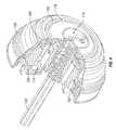
- FIG. 1is an exploded view of an example lock assembly according to one embodiment of the disclosure
- FIG. 2is a side cross-sectional view of the example lock assembly shown in FIG. 1 in an assembled state
- FIG. 3is an exploded view of the example exterior assembly shown in FIGS. 1 and 2 ;
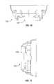
- FIG. 4is a front perspective view of the example exterior assembly shown in FIGS. 1 and 2 with a section removed to show interior components;
- FIG. 5is a partial side cross-sectional view of the example exterior assembly shown in FIGS. 1 and 2 ;
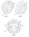
- FIG. 6is a rear perspective view of the example exterior assembly shown in FIGS. 1 and 2 ;
- FIG. 7is a rear perspective view of an example insulator top that could be used in the exterior assembly according to one embodiment of the disclosure.
- FIG. 8is a front perspective view of an example insulator shown in FIG. 7 ;
- FIG. 9is a rear view of the example insulator shown in FIGS. 7 and 8 ;
- FIG. 10is a sectional view of the example insulator along line 10 - 10 of FIG. 9 ;
- FIG. 11is a sectional view of the example insulator along line 11 - 11 of FIG. 9 ;
- FIG. 12is a rear perspective view of an example lockset body that could be used in the exterior assembly, according to one embodiment of the disclosure.
- FIG. 13is a front perspective view of an example lockset body shown in FIG. 12 ;
- FIG. 14is a rear view of the example lockset body shown in FIG. 12 ;
- FIG. 15is a sectional view of the example lockset body along line 15 - 15 of FIG. 14 ;
- FIG. 16is a front view of the example lockset body shown in FIG. 13 ;
- FIG. 17is a sectional view of the example lockset body along line 17 - 17 of FIG. 16 ;
- FIG. 18is a sectional view of the example lockset body along line 18 - 18 of FIG. 16 ;
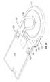
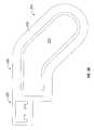
- FIG. 19is a front perspective view of an example light pipe that could be used in the exterior assembly according to one embodiment of the disclosure.
- FIG. 20is a rear perspective view of the example light pipe shown in FIG. 19 ;
- FIG. 21is a rear view of the example light pipe shown in FIG. 20 ;
- FIG. 22is a sectional view of the example light pipe along line 22 - 22 of FIG. 21 ;
- FIG. 23is a sectional view of the example light pipe along line 23 - 23 of FIG. 21 ;
- FIG. 24is a sectional view of the example light pipe along line 24 - 24 of FIG. 21 ;
- FIG. 25is a sectional view of the example light pipe along line 25 - 25 of FIG. 21 ;
- FIG. 26is a sectional view of the example light pipe along line 26 - 26 of FIG. 21 ;
- FIG. 27is a diagrammatical view showing an electrical connection from the lockset to the PCB through capacitive sensing
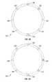
- FIGS. 28-31are a diagrammatical representation showing an example communication by the light pipe according to one embodiment of the disclosure.
- FIG. 32is an exploded view of an example battery contact assembly that may be used with a key fob could be used to wirelessly provide security credentials to the lock according to one embodiment of the disclosure;
- FIG. 33is a perspective view the example battery contact assembly shown in FIG. 32 mounted to a PCB assembly;
- FIG. 34is a perspective view of the example battery contact assembly shown in FIG. 33 with a battery inserted between the contacts;
- FIG. 35is a perspective view of the example battery contact assembly shown in FIG. 33 mounted on an opposite side of the PCB;
- FIG. 36is a bottom perspective view of a contact of the example battery contact assembly shown in FIG. 32 ;
- FIG. 37is a side perspective view of the example contact shown in FIG. 36 ;
- FIG. 38is a side view of the example contact shown in FIG. 36 ;
- FIG. 39is a top view of the example contact shown in FIG. 36 .
- electromechanical lockgenerally relates to an electromechanical lock with certain features.
- the term “electronic lock”is broadly intended to include any type of lockset that uses electrical power in some manner, including but not limited to electronic deadbolts, electronic lever sets, etc.
- This disclosureencompasses the integration of one or more of features described herein into any type of electronic lock and is not intended to be limited to any particular type of electronic lock.
- FIG. 1shows an example lock assembly 100 according to one embodiment of the disclosure.
- the lock assembly 100includes an exterior assembly 102 , a latch assembly 104 , and an interior assembly 106 .
- the exterior assembly 102is mounted on the outside of a door, while the interior assembly 106 is mounted inside a door.
- the latch assembly 104is typically mounted in a bore formed in the door.
- the term “outside”is broadly used to mean an area outside a door and “inside” is also broadly used to denote an area inside a door.
- the exterior entry doorfor example, the exterior assembly 102 may be mounted outside a building, while the interior assembly 106 may be mounted inside a building.
- the exterior assemblymay be mounted inside a building, but outside a room secured by the lock assembly 100 ; the interior assembly 106 may be mounted inside the secured room.
- the lock assembly 100is applicable to both interior and exterior doors.
- the exterior assembly 102is in the form of a deadbolt. As discussed above, however, this disclosure is not intended to be limited to only an electronic deadbolt, but encompasses any kind of electronic lock.
- the exterior assembly 102includes a cylinder guard cover 108 that houses internal components of the exterior assembly 102 .
- the cylinder guard cover 108has a decorative shape with a rear portion 110 that would be adjacent a door (not shown) and a front portion 112 extending from the door.
- the cylinder guard cover 108has a tapered shape from the rear portion 110 to the front portion 112 , but the exterior assembly 102 and cylinder guard 108 could have a wide variety of different sizes and shapes depending on the particular circumstances.
- the front portion 112 of the exterior assembly 102includes a front cover 114 that surrounds a mechanical locking assembly 116 .
- a mechanical key(not shown) may be inserted into the mechanical lock assembly 116 to mechanically unlock the lock assembly 100 .
- a light communication device 118surrounds the front cover 114 .
- the light communication device 118is formed in the shape of a ring surrounding the front cover 114 and mechanical lock assembly 116 .
- the light communication device 118could be formed in other shapes or positioned differently on the exterior assembly 102 .
- the light communication device 118includes a plurality of regions that could be independently controlled to visually communicate messages to the user, including but not limited to an action currently being processed by the lock assembly 100 , information about the status of the lock assembly 100 , and/or requests for user input.
- the light communication device 118could visually communicate the direction of bolt movement by illuminating regions in sequence to create a rotation animation showing a direction of movement.
- the light communication device 118could visually communicate messages to the user by controlling various attributes of the regions, such as turning regions on/off, changing intensity of regions, changing colors illuminated by regions, or other manners of changing the illumination of the light communication device 118 .
- the lock assembly 100may be touch activated.
- the lock assembly 100may use capacitive sensing to determine whether the user wants to actuate the lock 100 .
- the touch surface for capacitive sensing to actuate the lock assembly 100could be any external surface, including but not limited to a cylinder guard cover, cylinder guard, keyway, handle, rose, or other exterior surface of the lock assembly 100 .
- the exterior assembly 102uses capacitive sensing to determine when a user touches the cylinder guard cover 108 . Accordingly, in the embodiment shown, the user is able to touch anywhere on the cylinder guard cover 108 to lock or unlock the lock assembly 100 , or otherwise activate various functions of the lock assembly 100 .
- the exterior lock assembly 102has a torque blade 120 extending from the rear portion 110 .
- the torque bladeextends through an adaptor 122 in the embodiment shown, which is received within a bore in a door to which the lock assembly 100 is being installed or mounted.
- the latch assembly 104is disposed in a core in a door and may be actuated manually by the mechanical lock assembly 116 , or electronically by touching anywhere on the cylinder guard cover 108 (in the embodiment shown) to extend/retract a bolt 124 .
- the bolt 124moves linearly in and out of a sleeve 126 .
- an end of the bolt 124is generally flush with a base plate 128 .
- the bolt 124protrudes through an edge bore in the door into an opening 130 of a strike plate 132 , which is positioned in a jamb adjacent the door.
- the strike plate 132is attached to the jamb using fasteners 134 .
- fasteners 136attach the base plate 128 of the latch assembly 104 to a door.
- the latch assembly 104includes a spindle 138 that is drivable in a first direction to extend the bolt 124 and a second direction to retract the bolt 124 .
- the spindle 138is configured to receive the torque blade 120 such that rotation of the torque blade 120 in a first direction retracts the bolt 124 ; whereas, rotation of the torque blade 120 in the opposite direction causes the spindle to retract the bolt 124 .
- the torque blade 120extends through the latch assembly 104 into an opening 140 in a mounting plate 142 , which is attached to an interior side of a door.
- the torque blade 120passes through the opening 140 and is received by a spindle driver 144 .
- the spindle driver 144provides electronic control of the bolt 124 , such as using a motor to rotate the spindle driver 144 in either a first direction or in a second direction. Since the torque blade 120 is disposed within the spindle 138 , rotation of the spindle driver 144 may be used to extend and/or retract the bolt 124 of the latch assembly 104 .
- fasteners 146extend through holes 148 in the mounting plate, which are aligned with openings 150 in the latch assembly 104 .
- a wiring harness(not shown) electrically connects electronics between the exterior assembly 102 and the interior assembly 106 .
- FIG. 2is a side cross-sectional view of the lock assembly 100 in an assembled state.
- the torque blade 120can be seen extending from a rear portion 110 of the exterior assembly 102 through the spindle 138 of the latch assembly 104 into the spindle driver 144 of the interior assembly 106 .
- the torque blade 120may be driven to extend/retract the bolt 124 in several ways.
- the mechanical lock assembly 116could be actuated by a mechanical key to rotate the torque blade 120 , which would allow the bolt 124 to be moved extended/retracted.
- the exterior assembly 102could be used to electronically actuate the latch assembly 104 by touching anywhere on the cylinder guard cover 108 (assuming the lock assembly 100 received authenticated credentials prior to the user touching the cylinder guard cover 108 ).
- a messageis sent from the exterior assembly 102 to the interior assembly 106 using a wiring harness to actuate a motor in the interior assembly 106 that drives the torque blade 120 using the spindle driver 144 .
- a turn piece 152could be manually rotated by the user to actuate the torque blade 120 (via the spindle driver 144 ), thereby moving the bolt 124 between its extended and retracted positions.
- FIG. 3is an exploded view of the exterior assembly 102 .
- the mechanical locking assembly 116which could be a pin-tumbler locking arrangement, has a torque blade 120 extending therefrom.
- the front end of the mechanical locking assembly 116is received by an opening 154 in the front cover 118 .
- the front cover 118is made of a RF transparent material, such as a plastic.
- the front cover 118could be made of a material called Terluran GP-22 by BASF of Ludwigshafen, Germany or Polylac PA-727 by Chi Mei Corporation of Taiwan.
- the exterior assembly 102includes an insulator 156 that is received within the rear portion of the cylinder guard cover 108 .
- the insulator 156is formed from an electrical insulator material, such as Polycarbonate PC-110 by Chi Mei Corporation of Taiwan.
- the insulator 156includes a recessed portion 158 that houses several internal components.
- an o-ring 160 , a light pipe 162 , a PCB board 164 , and a conductive wave washer 166are housed in the recessed portion 158 between the insulator 156 and the cylinder guard cover 108 .
- the light communication device 118is a light pipe 162 .
- the light pipe 162includes a recessed portion 163 on the front end that is dimensioned to receive the front cover 118 .
- a flange 165which is a ring-shape in the embodiment shown, surrounding the front cover 118 can be selectively illuminated. Accordingly, in the embodiment shown, the flange 165 or ring surrounding the front cover 118 may light up during operation.
- the light pipe 162may include a plurality of regions that are independently controllable to visually display messages to the user, which could be animations in some embodiments.
- the light pipe 162is translucent or transparent.
- the light pipe 162could be made from a product called Polycarbonate PC-110 by Chi Mei Corporation of Taiwan. As shown, the light pipe 162 includes a groove dimensioned to receive a seal, which is an o-ring 160 in this example. The o-ring prevents moisture from entering the front portion 112 of the exterior assembly 102 .
- fasteners 168extend through the light pipe 162 PCB board and insulator 156 to connect within threaded openings 170 of a cylinder housing 172 .
- the cylinder housing (also called cylinder guard) 172provides impact strength and structural reinforcement for the exterior locking assembly 102 .
- the cylinder housing 172may be formed from a zinc alloy in some embodiments.
- the cylinder housing 172is received in a rear portion of the insulator 156 .
- the cylinder housing 172includes a cavity 174 that is configured to receive an antenna. Despite having a cavity in the cylinder housing 172 , the cylinder housing 172 provides sufficient reinforcement for the exterior assembly 102 in tests.
- a clip 176retains a rear portion of the mechanical locking assembly 116 within the exterior assembly 102 .
- a retainer 178 and plate 180are attached to a rear portion of the cylinder housing 172 for added tamper resistance and structural reinforcement of the cylinder housing 172 .
- Fasteners 182 , 184are received within threaded openings in the back portion of the cylinder housing 172 to fasten the retainer 178 and plate 180 .
- FIG. 4is a front perspective view of the external assembly 102 with a portion removed to expose internal components.
- the cavity 174 formed in the cylinder housing 172can be seen. This allows an antenna to be internal to the exterior assembly 102 (within the cylinder housing 172 as shown) to transmit signals outside the exterior assembly 102 .
- an antenna on the front portion of the exterior assembly 102behind the light pipe 162 and front cover 114 , which are both plastic, this allows wireless signals to be transmitted out of the exterior assembly 102 .
- the flange 165 of the light pipe 162extends around the front cover 118 , which can be used to communicate with the user.
- FIG. 5is a side cross-sectional view of a portion of the exterior assembly 102 .
- an air gap 186is formed by the insulator 156 between the cylinder guard cover 108 and the cylinder housing 172 .
- the insulator 156also separates the touch surface, which is the cylinder guard cover 108 in this example from the PCB 164 that hosts the touch electronics.
- a conductive wave washer 166is compressed between the PCB 164 and the cylinder guard cover 108 to make electrical contact. With this electrical connector, the PCB 164 can sense when a user touches anywhere on the cylinder guard cover 108 .
- the touch surfacecould be any mechanical feature of a lockset, including but not limited to a cylinder guard cover, cylinder guard, cylinder, keyway, handle, rose, or other exterior/interior features of a lockset.
- a conductive wave washer 166is shown for purposes of example, the conductive medium could be a conductive foam, conductive tape, conductive grease, or any other mechanical device electrically connecting the touch surface of the lockset to the PCB that hosts the touch electronics. This is shown diagrammatically in FIG. 27 . Also visible from the view is the cavity 174 for housing the antenna.
- FIG. 6is a rear perspective view of the exterior assembly 102 .
- the torque blade 120extends from the rear portion of the exterior assembly for actuating the spindle 138 and the latch assembly 104 .
- This viewalso shows the plate 180 and retainer 178 that have been attached to the rear portion of the cylinder housing 172 .
- FIGS. 28-31show an example of how the light pipe 162 (which is shown diagrammatically) may be used to communicate with the user.
- the light pipeincludes a plurality of regions that may be independently illuminated or adjusted by intensity or color. These regions may be illuminated in a coordinated manner to display information about the exterior assembly 102 , such as a static image (e.g., solid or flashing the same regions) or as an animation (e.g., illuminating regions in a particular sequence).
- the light pipe 162includes a first region 188 , a second region 190 , a third region 192 , a fourth region 194 , a fifth region 196 , a sixth region 198 , a seventh region 200 , and an eighth region 202 .
- eight regionsare shown in this example, more or fewer regions could be used. Although these regions are represented by a circle, these are merely shown for purposes of example to indicate a region of the light pipe 162 that may be independently drivable.
- One example communication that may be made by the light pipe 162could be indicating the direction of movement of the bolt 124 . If the bolt 124 was moving to the right, for example, the light pipe 162 may illuminate regions in a sequence to animate a clockwise movement. For example, the light pipe may first indicate the first and second regions 188 , 190 , as shown in FIG. 28 . The next two regions 192 , 194 may then be illuminated and then the next regions 196 , 198 and finally regions 200 , 202 to show an animation of a clockwise direction. If the bolt 124 was moving to the left, the animation could be in the opposite direction.
- the light pipe 162could be used to communicate a wide variety of information, such as whether the lock assembly 100 is either in a locked state or in an unlocked state. Moreover, in some embodiments, the light pipe 162 could be used to request additional information from a user, such as requesting the user touch the touch surface to either lock or unlock the lock assembly 100 . If the user needs to touch the cylinder guard cover 108 multiple times to activate a certain function of the lock assembly 100 , for example, the light pipe 162 could indicate the number of touches by flashing that number of times. Accordingly, the light pipe 162 acts as a user interface to communicate and interact with the user.
- the usermay approach the exterior assembly 102 , which could cause the light pipe 162 to illuminate to indicate the user is in range. If an authentication code transmitted by the user to the lock assembly 100 is authenticate or recognized, the light pipe 162 may indicate this, such as by flashing green or some sort of animation. The user may then touch anywhere on the cylinder guard cover 108 to unlock the lock assembly 100 . For example, this may cause a motor to rotate the spindle driver 144 , which rotates the torque blade 120 to retract the bolt 124 . As the lock assembly 100 is actuating the bolt to the retracted position, the light pipe 162 may indicate this through some sort of animation, such as a clockwise animation. When the bolt 124 has been fully retracted, the light pipe 162 may indicate that the bolt 124 is unlocked. If there was an error in retracting the bolt 124 , the light pipe 162 could indicate this.
- FIGS. 32-39show a battery contact assembly 210 for electrically connecting a battery 212 , such as a coin battery, to a PCB board 214 for supplying electrical power.
- this assemblycould be in a key fob that interacts with the lock assembly 100 .
- the PCB 214could be configured to transmit wireless messages to the lock assembly 100 , such as security credentials.
- the battery contact assembly 210is configured to provide a low-profile key fob that is thinner than existing key fobs.
- the battery contact assembly 210includes a first contact 216 and a second contact 218 .
- the first contact 216may connect a negative terminal of the battery 212 to the PCB 214 while the second contact 218 may connect the positive terminal of the battery 212 .
- the first contact 216includes a mounting portion 220 for mounting the first contact to the PCB 214 .
- the second contact 218includes a mounting portion 222 for mounting the second contact to the PCB 214 .
- the mounting portion 220includes legs 220 that extend through holes 226 in the PCB 214 for soldering the first contact 216 to the PCB 214 to establish an electrical connection between the PCB 214 and the first contact 216 .
- the mounting portion 220is mounted to the face of the PCB 214 (either the front or back as shown in FIGS. 34 and 35 ).
- a projection 228extends from the PCB 214 and is suspended above the second contact 218 .
- the projection 228includes a straight portion 230 that extends along a longitudinal axis of the PCB and an angled portion 232 .
- the projection 228includes a spring 234 surrounded by a holder 236 . The spring 234 urges against a first side of the battery to create a frictional fit with the second contact 218 .
- the mounting portion 222 of the second contact 218includes legs 238 that extend through holes 240 in the PCB 214 for soldering the second contact 218 to the PCB 214 to establish an electrical connection between the PCB 214 and the second contact 218 .
- the mounting portion 220includes a face portion 242 and an edge portion 244 to straddle the PCB 214 (See FIGS. 33-35 ).
- the edge portion 244has a top end extending transverse from the face portion 242 and a bottom end with a projection 246 extends from the PCB 214 and is positioned on an opposing side of the battery 212 than the first contact 216 .
- the second contact 218can be mounted to either the front or back of the PCB 214 .
- the projection 246includes a straight portion 248 that extends along a longitudinal axis of the PCB and an angled portion 250 .
- the projection 218includes a spring 252 surrounded by a holder 254 .
- the spring 252urges against a second side of the battery to create a frictional fit with the first contact 216 .
- a usermay slide a battery 212 between the first contact 216 and the second contact 218 .
- the urging of springs 234 , 252 on opposing faces of battery 212creates a frictional fit to hold the battery 212 in place.
- the battery 212supplies power to the PCB 214 . If the user wants to remove the battery 212 , the battery 212 may pulled out with sufficient force to overcome the friction of the springs 234 , 252 .
Landscapes
- Physics & Mathematics (AREA)
- General Physics & Mathematics (AREA)
- Engineering & Computer Science (AREA)
- Electromagnetism (AREA)
- Manufacturing & Machinery (AREA)
- Computer Networks & Wireless Communication (AREA)
- Mechanical Engineering (AREA)
- Lock And Its Accessories (AREA)
- Optical Communication System (AREA)
- General Engineering & Computer Science (AREA)
- Theoretical Computer Science (AREA)
- Signal Processing (AREA)
- Human Computer Interaction (AREA)
- Support Of Aerials (AREA)
Abstract
Description
Claims (19)
Priority Applications (8)
| Application Number | Priority Date | Filing Date | Title |
|---|---|---|---|
| US14/202,047US9024759B2 (en) | 2013-03-15 | 2014-03-10 | Wireless lockset with integrated antenna, touch activation, and light communication method |
| US29/486,952USD755037S1 (en) | 2014-03-10 | 2014-04-04 | Deadbolt with circular light |
| US14/689,766US10738504B2 (en) | 2013-03-15 | 2015-04-17 | Wireless lockset with integrated antenna, touch activation, and light communication method |
| US16/987,053US11408201B2 (en) | 2013-03-15 | 2020-08-06 | Wireless lockset with integrated antenna, touch activation, and light communication method |
| US17/167,325US11408202B2 (en) | 2013-03-15 | 2021-02-04 | Wireless lockset with integrated antenna, touch activation, and light communication method |
| US17/817,703US11913252B2 (en) | 2013-03-15 | 2022-08-05 | Wireless lockset with touch activation |
| US18/418,002US12320154B2 (en) | 2013-03-15 | 2024-01-19 | Wireless lockset with touch activation |
| US19/031,577US20250263952A1 (en) | 2013-03-15 | 2025-01-18 | Wireless lockset with integrated antenna, touch activation, and light communication method |
Applications Claiming Priority (2)
| Application Number | Priority Date | Filing Date | Title |
|---|---|---|---|
| US201361792896P | 2013-03-15 | 2013-03-15 | |
| US14/202,047US9024759B2 (en) | 2013-03-15 | 2014-03-10 | Wireless lockset with integrated antenna, touch activation, and light communication method |
Related Child Applications (2)
| Application Number | Title | Priority Date | Filing Date |
|---|---|---|---|
| US29/486,952Continuation-In-PartUSD755037S1 (en) | 2014-03-10 | 2014-04-04 | Deadbolt with circular light |
| US14/689,766ContinuationUS10738504B2 (en) | 2013-03-15 | 2015-04-17 | Wireless lockset with integrated antenna, touch activation, and light communication method |
Publications (2)
| Publication Number | Publication Date |
|---|---|
| US20140260449A1 US20140260449A1 (en) | 2014-09-18 |
| US9024759B2true US9024759B2 (en) | 2015-05-05 |
Family
ID=50391493
Family Applications (7)
| Application Number | Title | Priority Date | Filing Date |
|---|---|---|---|
| US14/202,047ActiveUS9024759B2 (en) | 2013-03-15 | 2014-03-10 | Wireless lockset with integrated antenna, touch activation, and light communication method |
| US14/689,766Active2037-05-24US10738504B2 (en) | 2013-03-15 | 2015-04-17 | Wireless lockset with integrated antenna, touch activation, and light communication method |
| US16/987,053Active2034-04-19US11408201B2 (en) | 2013-03-15 | 2020-08-06 | Wireless lockset with integrated antenna, touch activation, and light communication method |
| US17/167,325ActiveUS11408202B2 (en) | 2013-03-15 | 2021-02-04 | Wireless lockset with integrated antenna, touch activation, and light communication method |
| US17/817,703ActiveUS11913252B2 (en) | 2013-03-15 | 2022-08-05 | Wireless lockset with touch activation |
| US18/418,002ActiveUS12320154B2 (en) | 2013-03-15 | 2024-01-19 | Wireless lockset with touch activation |
| US19/031,577PendingUS20250263952A1 (en) | 2013-03-15 | 2025-01-18 | Wireless lockset with integrated antenna, touch activation, and light communication method |
Family Applications After (6)
| Application Number | Title | Priority Date | Filing Date |
|---|---|---|---|
| US14/689,766Active2037-05-24US10738504B2 (en) | 2013-03-15 | 2015-04-17 | Wireless lockset with integrated antenna, touch activation, and light communication method |
| US16/987,053Active2034-04-19US11408201B2 (en) | 2013-03-15 | 2020-08-06 | Wireless lockset with integrated antenna, touch activation, and light communication method |
| US17/167,325ActiveUS11408202B2 (en) | 2013-03-15 | 2021-02-04 | Wireless lockset with integrated antenna, touch activation, and light communication method |
| US17/817,703ActiveUS11913252B2 (en) | 2013-03-15 | 2022-08-05 | Wireless lockset with touch activation |
| US18/418,002ActiveUS12320154B2 (en) | 2013-03-15 | 2024-01-19 | Wireless lockset with touch activation |
| US19/031,577PendingUS20250263952A1 (en) | 2013-03-15 | 2025-01-18 | Wireless lockset with integrated antenna, touch activation, and light communication method |
Country Status (12)
| Country | Link |
|---|---|
| US (7) | US9024759B2 (en) |
| EP (1) | EP2971416A2 (en) |
| JP (1) | JP6001208B2 (en) |
| KR (2) | KR102038746B1 (en) |
| CN (2) | CN105484576B (en) |
| AU (3) | AU2014237417B2 (en) |
| CA (1) | CA2906405A1 (en) |
| CL (1) | CL2015002711A1 (en) |
| MX (1) | MX355745B (en) |
| PE (1) | PE20151898A1 (en) |
| PH (1) | PH12015502109B1 (en) |
| WO (1) | WO2014150172A2 (en) |
Cited By (52)
| Publication number | Priority date | Publication date | Assignee | Title |
|---|---|---|---|---|
| US20140260451A1 (en)* | 2013-03-15 | 2014-09-18 | Kwikset Corporation | Electro-mechanical locks with bezel turning function |
| US20150218850A1 (en)* | 2013-03-15 | 2015-08-06 | Spectrum Brands, Inc. | Wireless lockset with integrated antenna, touch activation, and light communication method |
| CN105089371A (en)* | 2015-09-10 | 2015-11-25 | 武汉普林光通科技有限公司 | Control method of electronic lock and electronic lock of this type |
| US20160047145A1 (en)* | 2013-03-15 | 2016-02-18 | August Home, Inc. | Intelligent Door Lock System and Vibration/Tapping Sensing Device to Lock or Unlock a Door |
| US20160133071A1 (en)* | 2014-11-07 | 2016-05-12 | Kevin Henderson | Electronic lock |
| WO2017095766A1 (en) | 2015-12-01 | 2017-06-08 | Spectrum Brands, Inc. | Electronic lock with misalignment scoring system |
| WO2017180688A1 (en) | 2016-04-15 | 2017-10-19 | Spectrum Brands, Inc. | Wireless lockset with integrated angle of arrival (aoa) detection |
| US20180066450A1 (en)* | 2016-09-07 | 2018-03-08 | Sargent Manufacturing Company | Bored lock occupancy indicator |
| US9916746B2 (en) | 2013-03-15 | 2018-03-13 | August Home, Inc. | Security system coupled to a door lock system |
| US10304273B2 (en) | 2013-03-15 | 2019-05-28 | August Home, Inc. | Intelligent door lock system with third party secured access to a dwelling |
| WO2019106020A1 (en) | 2017-11-28 | 2019-06-06 | Urban Infrastructure Partner As | Bicycle locking system |
| US20190213813A1 (en)* | 2018-01-05 | 2019-07-11 | Spectrum Brands, Inc. | Touch isolated electronic lock |
| US10388094B2 (en) | 2013-03-15 | 2019-08-20 | August Home Inc. | Intelligent door lock system with notification to user regarding battery status |
| US10443266B2 (en) | 2013-03-15 | 2019-10-15 | August Home, Inc. | Intelligent door lock system with manual operation and push notification |
| US10691953B2 (en) | 2013-03-15 | 2020-06-23 | August Home, Inc. | Door lock system with one or more virtual fences |
| US10829956B2 (en) | 2018-07-09 | 2020-11-10 | Schlage Lock Company Llc | Automatic sliding panel deadbolt lock assembly |
| US10846957B2 (en) | 2013-03-15 | 2020-11-24 | August Home, Inc. | Wireless access control system and methods for intelligent door lock system |
| US10930097B2 (en) | 2016-04-19 | 2021-02-23 | Spectrum Brands, Inc. | Lockset with integrated wireless signals analysis feature and method |
| US10968660B2 (en)* | 2018-02-28 | 2021-04-06 | Passivebolt, Inc. | Electronic door lock |
| US10970983B2 (en) | 2015-06-04 | 2021-04-06 | August Home, Inc. | Intelligent door lock system with camera and motion detector |
| US10993111B2 (en) | 2014-03-12 | 2021-04-27 | August Home Inc. | Intelligent door lock system in communication with mobile device that stores associated user data |
| US11002061B1 (en) | 2020-01-04 | 2021-05-11 | Passivebolt, Inc. | Electronic door system |
| US11043055B2 (en) | 2013-03-15 | 2021-06-22 | August Home, Inc. | Door lock system with contact sensor |
| US11072945B2 (en) | 2013-03-15 | 2021-07-27 | August Home, Inc. | Video recording triggered by a smart lock device |
| US11091936B2 (en) | 2017-05-23 | 2021-08-17 | Spectrum Brands, Inc. | Door handing assembly for electromechanical locks |
| US11105121B2 (en)* | 2019-02-14 | 2021-08-31 | Schlage Lock Company Llc | Rugged credential input assemblies |
| US11156020B2 (en) | 2018-05-29 | 2021-10-26 | Spectrum Brands, Inc. | Tamper alarm for electronic lock |
| US11158145B2 (en) | 2016-03-22 | 2021-10-26 | Spectrum Brands, Inc. | Garage door opener with touch sensor authentication |
| TWI750291B (en)* | 2018-01-05 | 2021-12-21 | 美商品譜公司 | Touch isolated electronic lock |
| US20220106814A1 (en)* | 2020-10-06 | 2022-04-07 | Assa Abloy Access And Egress Hardware Group, Inc. | Electronic locking device |
| US11339589B2 (en) | 2018-04-13 | 2022-05-24 | Dormakaba Usa Inc. | Electro-mechanical lock core |
| US11352812B2 (en) | 2013-03-15 | 2022-06-07 | August Home, Inc. | Door lock system coupled to an image capture device |
| US11421445B2 (en) | 2013-03-15 | 2022-08-23 | August Home, Inc. | Smart lock device with near field communication |
| US11441332B2 (en) | 2013-03-15 | 2022-09-13 | August Home, Inc. | Mesh of cameras communicating with each other to follow a delivery agent within a dwelling |
| US11466473B2 (en) | 2018-04-13 | 2022-10-11 | Dormakaba Usa Inc | Electro-mechanical lock core |
| US11501587B2 (en)* | 2018-06-07 | 2022-11-15 | Southco, Inc. | Electronic access system and method for retrofitting an electronic access system |
| US11501579B2 (en) | 2019-11-26 | 2022-11-15 | Spectrum Brands, Inc. | System and method of enrolling users of a wireless biometric lockset |
| US11527121B2 (en) | 2013-03-15 | 2022-12-13 | August Home, Inc. | Door lock system with contact sensor |
| US11560736B2 (en) | 2020-03-04 | 2023-01-24 | Endura Products, Llc | Method for operating a door and components related to the same |
| US11639617B1 (en) | 2019-04-03 | 2023-05-02 | The Chamberlain Group Llc | Access control system and method |
| TWI804975B (en)* | 2021-09-08 | 2023-06-11 | 一德金屬工業股份有限公司 | Management method of electronic locks |
| TWI808546B (en)* | 2018-01-05 | 2023-07-11 | 美商品譜公司 | Touch isolated electronic lock |
| US11739564B2 (en) | 2020-03-04 | 2023-08-29 | Endura Products, Llc | Method for operating a door and components related to the same |
| US11802422B2 (en) | 2013-03-15 | 2023-10-31 | August Home, Inc. | Video recording triggered by a smart lock device |
| US11821236B1 (en) | 2021-07-16 | 2023-11-21 | Apad Access, Inc. | Systems, methods, and devices for electronic dynamic lock assembly |
| US11846121B2 (en) | 2017-06-02 | 2023-12-19 | Lock Ii, Llc | Device and methods for providing a lock for preventing unwanted access to a locked enclosure |
| US11913254B2 (en) | 2017-09-08 | 2024-02-27 | dormakaba USA, Inc. | Electro-mechanical lock core |
| US11920372B2 (en) | 2019-11-22 | 2024-03-05 | Assa Abloy Americas Residential Inc. | Sealing of an electronic lock |
| US11933076B2 (en) | 2016-10-19 | 2024-03-19 | Dormakaba Usa Inc. | Electro-mechanical lock core |
| US11959308B2 (en) | 2020-09-17 | 2024-04-16 | ASSA ABLOY Residential Group, Inc. | Magnetic sensor for lock position |
| US12067855B2 (en) | 2020-09-25 | 2024-08-20 | ASSA ABLOY Residential Group, Inc. | Door lock with magnetometers |
| US12180750B2 (en) | 2020-09-25 | 2024-12-31 | Assa Abloy Residential Group Inc. | Multi orientation door lock |
Families Citing this family (59)
| Publication number | Priority date | Publication date | Assignee | Title |
|---|---|---|---|---|
| US20180343141A1 (en) | 2015-09-22 | 2018-11-29 | SkyBell Technologies, Inc. | Doorbell communication systems and methods |
| US10440165B2 (en) | 2013-07-26 | 2019-10-08 | SkyBell Technologies, Inc. | Doorbell communication and electrical systems |
| US10708404B2 (en) | 2014-09-01 | 2020-07-07 | Skybell Technologies Ip, Llc | Doorbell communication and electrical systems |
| US11004312B2 (en) | 2015-06-23 | 2021-05-11 | Skybell Technologies Ip, Llc | Doorbell communities |
| US10672238B2 (en) | 2015-06-23 | 2020-06-02 | SkyBell Technologies, Inc. | Doorbell communities |
| US10044519B2 (en) | 2015-01-05 | 2018-08-07 | SkyBell Technologies, Inc. | Doorbell communication systems and methods |
| US11889009B2 (en) | 2013-07-26 | 2024-01-30 | Skybell Technologies Ip, Llc | Doorbell communication and electrical systems |
| US11837040B2 (en) | 2013-07-26 | 2023-12-05 | Skybell Technologies Ip, Llc | Smart lock systems and methods |
| US9736284B2 (en) | 2013-07-26 | 2017-08-15 | SkyBell Technologies, Inc. | Doorbell communication and electrical systems |
| US10204467B2 (en) | 2013-07-26 | 2019-02-12 | SkyBell Technologies, Inc. | Smart lock systems and methods |
| US9142214B2 (en) | 2013-07-26 | 2015-09-22 | SkyBell Technologies, Inc. | Light socket cameras |
| US20170263067A1 (en) | 2014-08-27 | 2017-09-14 | SkyBell Technologies, Inc. | Smart lock systems and methods |
| US9769435B2 (en) | 2014-08-11 | 2017-09-19 | SkyBell Technologies, Inc. | Monitoring systems and methods |
| US10733823B2 (en) | 2013-07-26 | 2020-08-04 | Skybell Technologies Ip, Llc | Garage door communication systems and methods |
| US9342936B2 (en) | 2013-07-26 | 2016-05-17 | SkyBell Technologies, Inc. | Smart lock systems and methods |
| US8947530B1 (en) | 2013-07-26 | 2015-02-03 | Joseph Frank Scalisi | Smart lock systems and methods |
| US11651665B2 (en) | 2013-07-26 | 2023-05-16 | Skybell Technologies Ip, Llc | Doorbell communities |
| US9743049B2 (en) | 2013-12-06 | 2017-08-22 | SkyBell Technologies, Inc. | Doorbell communication systems and methods |
| US9786133B2 (en) | 2013-12-06 | 2017-10-10 | SkyBell Technologies, Inc. | Doorbell chime systems and methods |
| US9799183B2 (en) | 2013-12-06 | 2017-10-24 | SkyBell Technologies, Inc. | Doorbell package detection systems and methods |
| US9932756B1 (en)* | 2014-01-06 | 2018-04-03 | Mark Nickeas | Electronic barrel lock and key system |
| US10687029B2 (en) | 2015-09-22 | 2020-06-16 | SkyBell Technologies, Inc. | Doorbell communication systems and methods |
| US9888216B2 (en) | 2015-09-22 | 2018-02-06 | SkyBell Technologies, Inc. | Doorbell communication systems and methods |
| US20170085843A1 (en) | 2015-09-22 | 2017-03-23 | SkyBell Technologies, Inc. | Doorbell communication systems and methods |
| US11184589B2 (en) | 2014-06-23 | 2021-11-23 | Skybell Technologies Ip, Llc | Doorbell communication systems and methods |
| US9997036B2 (en) | 2015-02-17 | 2018-06-12 | SkyBell Technologies, Inc. | Power outlet cameras |
| US11575537B2 (en) | 2015-03-27 | 2023-02-07 | Skybell Technologies Ip, Llc | Doorbell communication systems and methods |
| US10553088B2 (en) | 2015-01-12 | 2020-02-04 | Jonathan Lee | Security device for integration into a security system |
| US9911293B2 (en)* | 2015-01-12 | 2018-03-06 | Jonathan Lee | Security device for integration into a security system |
| US10742938B2 (en) | 2015-03-07 | 2020-08-11 | Skybell Technologies Ip, Llc | Garage door communication systems and methods |
| US11381686B2 (en) | 2015-04-13 | 2022-07-05 | Skybell Technologies Ip, Llc | Power outlet cameras |
| CN104895416B (en)* | 2015-06-11 | 2017-06-30 | 北京艾科斯玛特自动化控制技术有限公司 | Intelligent lock core |
| US20180047269A1 (en) | 2015-06-23 | 2018-02-15 | SkyBell Technologies, Inc. | Doorbell communities |
| US10706702B2 (en) | 2015-07-30 | 2020-07-07 | Skybell Technologies Ip, Llc | Doorbell package detection systems and methods |
| WO2017172871A1 (en) | 2016-03-31 | 2017-10-05 | Spectrum Brands, Inc. | Locking device with multiple authentication devices |
| CN105735854B (en)* | 2016-04-14 | 2018-01-19 | 湖南湘联节能科技股份有限公司 | A kind of burglary-resisting system |
| US10043332B2 (en) | 2016-05-27 | 2018-08-07 | SkyBell Technologies, Inc. | Doorbell package detection systems and methods |
| MX2019000131A (en) | 2016-07-05 | 2019-09-04 | Salunda Ltd | Sensor for a fingerboard latch assembly. |
| US10240363B2 (en)* | 2017-01-03 | 2019-03-26 | Spectrum Brands, Inc. | Deadbolt lock assembly with visual feedback |
| USD927285S1 (en) | 2017-08-02 | 2021-08-10 | Spectrum Brands, Inc. | Deadbolt faceplate with LED strip having animated illumination |
| WO2019036894A1 (en)* | 2017-08-22 | 2019-02-28 | 深圳市柔宇科技有限公司 | Touch control electronic door lock, and door |
| TWD187759S (en)* | 2017-09-05 | 2018-01-11 | 台灣福興工業股份有限公司 | Knob of lock |
| US10909825B2 (en) | 2017-09-18 | 2021-02-02 | Skybell Technologies Ip, Llc | Outdoor security systems and methods |
| AU2018383754B2 (en)* | 2017-12-12 | 2024-06-06 | Level Home, Inc. | Door lock bezel with touch and wireless capabilities |
| TWI645100B (en)* | 2018-02-07 | 2018-12-21 | 台灣福興工業股份有限公司 | Lock structure with mounted plate and mounting method thereof |
| AU2019202084B2 (en)* | 2018-04-02 | 2020-10-22 | Assa Abloy Korea | A driving assembly for a lever-type door lock |
| KR101899127B1 (en)* | 2018-05-28 | 2018-10-04 | (주)필리아테크놀러지 | Digital door lock assembly |
| US20200024867A1 (en)* | 2018-07-18 | 2020-01-23 | Nexkey, Inc. | Wireless electric lock core |
| CN109687094A (en)* | 2018-11-03 | 2019-04-26 | 宇起数字科技(上海)有限公司 | A kind of connection type of lock body antenna |
| US10657795B1 (en) | 2019-02-01 | 2020-05-19 | SimpliSafe, Inc. | Alarm system with first responder code for building access |
| USD912492S1 (en)* | 2019-05-20 | 2021-03-09 | Altro Smart Inc. | Lock set |
| US11933092B2 (en) | 2019-08-13 | 2024-03-19 | SimpliSafe, Inc. | Mounting assembly for door lock |
| WO2021041354A1 (en) | 2019-08-24 | 2021-03-04 | Skybell Technologies Ip, Llc | Doorbell communication systems and methods |
| CA3159471A1 (en)* | 2019-12-05 | 2021-06-10 | Kenneth D. GOTO | Smart door lock |
| CA3185592A1 (en)* | 2020-07-10 | 2022-01-13 | Oscar Romero | Sliding deadbolt |
| US20230065459A1 (en)* | 2021-08-26 | 2023-03-02 | Carrier Corporation | Door lock with authentication module |
| US11746560B2 (en) | 2021-11-11 | 2023-09-05 | Schlage Lock Company Llc | Handle catch assemblies |
| KR20230082839A (en)* | 2021-12-02 | 2023-06-09 | 삼성전자주식회사 | Electronic device including emitter |
| US20240309676A1 (en)* | 2023-03-16 | 2024-09-19 | Assa Abloy Americas Residential Inc. | Lock assembly and method of installing the same |
Citations (169)
| Publication number | Priority date | Publication date | Assignee | Title |
|---|---|---|---|---|
| US3733861A (en) | 1972-01-19 | 1973-05-22 | Recognition Devices | Electronic recognition door lock |
| US3794848A (en) | 1972-05-25 | 1974-02-26 | S Peters | Locking apparatus |
| USRE29341E (en) | 1972-05-25 | 1977-08-02 | Locking apparatus | |
| US4439808A (en) | 1980-07-28 | 1984-03-27 | Bsg (Security) Limited | Electromagnetic lock |
| US4573720A (en) | 1983-09-01 | 1986-03-04 | Nicolai J Steven | Failsafe security lock |
| US4685316A (en) | 1986-03-24 | 1987-08-11 | Hicks Harry H | Window guard latch with emergency release |
| US4763937A (en) | 1986-09-11 | 1988-08-16 | Sittnick Jr Ralph A | Electromagnetic door lock system |
| US5000497A (en) | 1990-03-26 | 1991-03-19 | Arthur Geringer | Electromagnetic door lock device |
| US5029912A (en) | 1990-04-09 | 1991-07-09 | Motohiro Gotanda | Locking device |
| US5088779A (en) | 1989-08-28 | 1992-02-18 | Harcor Security Seals Pty Limited | Door latch release mechanism |
| WO1993009319A1 (en) | 1991-11-08 | 1993-05-13 | Wilkenheights Limited | Improvements in and relating to locks |
| US5247282A (en) | 1991-12-11 | 1993-09-21 | Sharron Marshall | Delivery signal and appliance control system |
| US5261260A (en) | 1992-12-16 | 1993-11-16 | Lin Chen Che | Remote-control door lock for a dog cage |
| US5392025A (en) | 1993-09-24 | 1995-02-21 | Intermark Corporation | Electronic security system for display cabinets |
| US5429399A (en) | 1992-10-22 | 1995-07-04 | Geringer; Arthur | Electronic delayed egress locking system |
| US5474342A (en)* | 1993-08-04 | 1995-12-12 | Smith; Jerry R. | Door latch actuator |
| US5712626A (en) | 1991-09-19 | 1998-01-27 | Master Lock Company | Remotely-operated self-contained electronic lock security system assembly |
| US5729198A (en) | 1996-10-25 | 1998-03-17 | Gorman; Kim Ramsey | Wireless residential door unlatch system |
| US5799518A (en) | 1997-01-22 | 1998-09-01 | Suetech Industries Co., Ltd. | Door lock assembly |
| US5920268A (en) | 1996-10-11 | 1999-07-06 | Newtyme, Inc. | Keyless entry systems for use with conventional locksets |
| US5926106A (en) | 1997-05-12 | 1999-07-20 | Bc Creations, Inc. | Access control using serial discretely coded RF transmissions initiated by a single event |
| US5933086A (en) | 1991-09-19 | 1999-08-03 | Schlage Lock Company | Remotely-operated self-contained electronic lock security system assembly |
| US5936544A (en) | 1997-09-30 | 1999-08-10 | Pittway Corporation | Wireless access system |
| US5943888A (en) | 1997-12-15 | 1999-08-31 | Lawson; Edward | Keyless entry mechanism |
| US5987818A (en) | 1998-10-21 | 1999-11-23 | Dabideen; Pooran | Remotely controlled door locking and opening system |
| US5996383A (en)* | 1996-07-31 | 1999-12-07 | Emhart, Inc. | Lockset with motion detection and ambient light sensors |
| US6005306A (en) | 1998-08-14 | 1999-12-21 | Jon J. Dillon | Remote control door lock system |
| US6112563A (en) | 1998-10-02 | 2000-09-05 | Ramos; Israel | Remote control locking device |
| US6128933A (en)* | 1998-08-07 | 2000-10-10 | Emhart Inc. | Adjustable interconnected lock |
| US6271751B1 (en) | 1999-08-24 | 2001-08-07 | Securitron Magnalock Corp. | Magnetic lock and status detection system and method therefor |
| US6323782B1 (en) | 1999-06-21 | 2001-11-27 | Freight Locker, Inc. | Unattended item delivery system |
| US20020109582A1 (en) | 2001-02-15 | 2002-08-15 | Mooney Philip D. | Recharging key based wireless device |
| US20020140542A1 (en) | 2001-04-02 | 2002-10-03 | Prokoski Francine J. | Personal biometric key |
| US20030084691A1 (en) | 2001-11-06 | 2003-05-08 | Konami Corporation | Locking device, locker, key and locking method |
| US20030114206A1 (en) | 2001-08-24 | 2003-06-19 | United Parcel Service Of America, Inc. | Portable data acquisition and management system and associated device and method |
| US20030230124A1 (en) | 2002-06-18 | 2003-12-18 | Johnson Ronald J. | Container with a selective opening and closing mechanism |
| US20040011094A1 (en) | 2002-07-22 | 2004-01-22 | Hui-Hua Hsieh | Remote-controlled door lock |
| US20040035160A1 (en) | 2002-02-22 | 2004-02-26 | Glenn Meekma | Radio frequency electronic lock |
| US6725127B2 (en) | 2000-05-25 | 2004-04-20 | Ebox Inc. | Package delivery system |
| US20040183652A1 (en) | 2003-03-21 | 2004-09-23 | Deng Sheng Bill | Door lock and operation mechanism |
| US20040257209A1 (en) | 2003-06-18 | 2004-12-23 | Wu-Chung Yang | Auto anti-thief system employing bluetooth technique |
| US20050035848A1 (en) | 2003-08-15 | 2005-02-17 | Syed Majid Ali | Network directed embedded transceiver lock system and method |
| US20050046545A1 (en) | 1997-05-20 | 2005-03-03 | Johnson Controls Technology Company | Trainable transceiver |
| US20050204787A1 (en) | 2004-03-19 | 2005-09-22 | Nick Ernst | Hotel in-room safe automated control and communication system |
| US6957767B2 (en) | 2003-06-30 | 2005-10-25 | International Business Machines Corporation | RFID-keyed mailbox, and RFID-based system and method for securing a mailbox |
| US20050237166A1 (en) | 2004-03-31 | 2005-10-27 | Tung Thih Enterprise Co., Ltd. | Vehicle anti-thief device with bluetooth recognition |
| US6967562B2 (en) | 2002-02-22 | 2005-11-22 | Royal Thoughts, Llc | Electronic lock control and sensor module for a wireless system |
| US6976919B2 (en) | 2001-06-05 | 2005-12-20 | Cole Industries, Inc. | Gaming unit including currency container locking mechanism |
| US20050279823A1 (en) | 2004-06-18 | 2005-12-22 | Mitchell Ernst K | Electronic lock with visual interface |
| US20060000247A1 (en)* | 1999-12-08 | 2006-01-05 | Moon Charles W | Electronic lock |
| US20060022794A1 (en) | 2004-07-27 | 2006-02-02 | Determan Gary E | Identification with RFID asset locator for entry authorization |
| US20060092378A1 (en)* | 2004-10-29 | 2006-05-04 | Marsden Andrew W | Illuminated security gate unit |
| US20060103545A1 (en) | 2004-11-18 | 2006-05-18 | Hsien-Chun Tsou | Remote Controller Capable of Selectively Controlling a Plurality of Electric Appliances, Remote Control System and Method thereof |
| US20060113368A1 (en) | 2004-11-29 | 2006-06-01 | Joseph Dudley | Theft Preventative Mailbox having Remote Unlocking Activation Mechanism |
| EP1710753A2 (en) | 2005-04-08 | 2006-10-11 | Computerized Security Systems | Door lock with RFID key |
| US20060266089A1 (en) | 2005-05-26 | 2006-11-30 | Dimig Steven J | Hybrid key |
| US20060273879A1 (en) | 2003-08-13 | 2006-12-07 | Herbert Pudelko | Method and device for securing a vehicle against theft |
| US20060283219A1 (en) | 2003-09-04 | 2006-12-21 | David Bendz | Device at lock |
| US7165428B2 (en) | 2002-01-26 | 2007-01-23 | Ison Limited | Lock |
| US20070083921A1 (en) | 2005-10-11 | 2007-04-12 | Parris Earl H | Configurable portable containers |
| US20070090921A1 (en) | 2005-10-26 | 2007-04-26 | Sentrilock, Inc. | Electronic lock box with key presence sensing |
| US20070115094A1 (en) | 2004-03-12 | 2007-05-24 | Joachim Gillert | Locking cylinder and closing method |
| US20070126562A1 (en) | 2005-12-07 | 2007-06-07 | Samsung Electronics Co., Ltd. | Security system and method using mobile terminal |
| US7239238B2 (en) | 2004-03-30 | 2007-07-03 | E. J. Brooks Company | Electronic security seal |
| US20070163863A1 (en)* | 2006-01-17 | 2007-07-19 | Computerized Security Systems, Inc. | Water resistant keycard reader assembly for an electronic lock |
| US7248836B2 (en) | 2001-09-30 | 2007-07-24 | Schlage Lock Company | RF channel linking method and system |
| US20070176739A1 (en) | 2006-01-19 | 2007-08-02 | Fonekey, Inc. | Multifunction keyless and cardless method and system of securely operating and managing housing facilities with electronic door locks |
| US20070204663A1 (en) | 2004-03-16 | 2007-09-06 | Irevo, Inc. | Easy-To-Retrofit, Electronically Controlled Door Lock System |
| US20070214848A1 (en) | 2003-05-09 | 2007-09-20 | Simonsvoss Technologies Ag | Electronic access control device |
| US20070226142A1 (en) | 1998-11-25 | 2007-09-27 | Diebold, Incorporated | Remote communication of deposit data from deposit bag RFID tag to depository |
| US7289764B2 (en) | 2001-09-30 | 2007-10-30 | Harrow Products, Llc | Cardholder interface for an access control system |
| US20070257773A1 (en) | 2006-04-26 | 2007-11-08 | Compx International Inc. | Field retrofittable refrigerator lock with audit trail |
| US7296448B1 (en) | 2001-02-22 | 2007-11-20 | Shaw Barry M | Electromagnetic integrative door locking device |
| US7304572B2 (en) | 2004-06-29 | 2007-12-04 | Motorola, Inc. | Cellular communications based intercom system and methods |
| US20070290793A1 (en) | 2006-06-12 | 2007-12-20 | Tran Bao Q | Mesh network door lock |
| US7346331B2 (en) | 2001-09-30 | 2008-03-18 | Harrow Products, Llc | Power management for locking system |
| US7346439B2 (en) | 2002-11-07 | 2008-03-18 | International Business Machines Corporation | Location-based intelligent remote vehicle function control |
| US7378939B2 (en) | 2004-03-30 | 2008-05-27 | Sengupta Uttam K | Method and apparatus for providing proximity based authentication, security, and notification in a wireless system |
| US20080129059A1 (en) | 2006-12-02 | 2008-06-05 | Chen-Fei Chang | LC Oscillation-Based Magnetic Lock |
| US20080134732A1 (en) | 2005-03-30 | 2008-06-12 | Birepo Aps | Key Box for Locked Storage of Coded Access Items Such as Access Cards and Keys |
| US7389661B2 (en) | 2004-09-24 | 2008-06-24 | Viviano Robert J | Keyless deadbolt door lock assembly |
| US7391319B1 (en) | 2005-08-22 | 2008-06-24 | Walker Ethan A | Wireless fire alarm door unlocking interface |
| US20080186171A1 (en) | 2007-02-01 | 2008-08-07 | Gates Tell A | Light powered perimeter alarm monitoring system |
| US20080196457A1 (en) | 2007-02-08 | 2008-08-21 | Ilan Goldman | Combination lock with light indicators |
| US20080252414A1 (en) | 2005-07-18 | 2008-10-16 | Law Enforcement Intelligent Devices, Llc | Biometric access control system incorporating a touchscreen accessible and kiosk based id station operating in combination with multiple critical asset retaining racks and locers for permitting selective biometric input and processor driven/wireless release authorization, maintenance and inventory control of any plurality of critical assets and including an associated computer writeable medium operating with the id station for enabling asset release, reentry and associated inventory control |
| US20080250716A1 (en) | 2007-04-12 | 2008-10-16 | The Stanley Works | Delayed egress sliding door and method |
| US7446644B2 (en) | 2005-01-14 | 2008-11-04 | Secureall Corporation | Universal hands free key and lock system |
| US20080278335A1 (en) | 2007-05-08 | 2008-11-13 | Welte Gregory A | Automated pet entry door |
| US20080289383A1 (en) | 2007-05-25 | 2008-11-27 | Levine Jonathan E | Door lock indicator |
| US20080303630A1 (en) | 2007-06-06 | 2008-12-11 | Danilo Jose Martinez | DigiKey and DigiLock |
| US20080314097A1 (en) | 2005-07-04 | 2008-12-25 | Huf Hulsbeck & Furst Gmbh & Co. Kg | Handle Device |
| US7471191B2 (en) | 2003-12-16 | 2008-12-30 | J. C. Decaux Sa | Automatic cycle storage system |
| US7481471B2 (en) | 2003-09-11 | 2009-01-27 | Baby Dan A/S | Child safety barrier with a locking device |
| US20090108596A1 (en) | 2005-07-29 | 2009-04-30 | Terahop Networks, Inc. | Shipping container security system |
| US20090135015A1 (en) | 2007-11-26 | 2009-05-28 | Dobson Eric L | Locking apparatus for shipping containers |
| US20090151410A1 (en) | 2006-09-12 | 2009-06-18 | Hapke Kenyon A | Vending machine lock system |
| US20090173119A1 (en) | 2008-01-08 | 2009-07-09 | Hunt Robert C | Electromagnetic Lock Monitoring System |
| US20090183541A1 (en) | 2006-04-28 | 2009-07-23 | Babak Sadighi | Access Control System and Method for Operating Said System |
| US20090201127A1 (en) | 2008-02-13 | 2009-08-13 | Anatoli Stobbe | Bicycle securing system |
| US20090211319A1 (en) | 2008-02-22 | 2009-08-27 | Mccormack Scott Alexander | Locks and inserts therefor |
| US20090223265A1 (en) | 2008-03-06 | 2009-09-10 | Tzu-Wei Chang | Pick-resistant lock system |
| US20090231132A1 (en) | 2006-03-29 | 2009-09-17 | S&S X-Ray Systems, Inc. | Remotely Actuated Refrigerator Lock with Thermal Spoilage Protection |
| US20090249846A1 (en) | 2006-05-31 | 2009-10-08 | Gokcebay Asil T | Electronic lock for cabinet doors, drawers and other applications |
| US20090273440A1 (en) | 2003-05-09 | 2009-11-05 | Marschalek James S | Electronic access control handle set for a door lock |
| US20090280862A1 (en) | 2004-07-22 | 2009-11-12 | Stanton Concepts Inc. | Tool Operated Combination Lock |
| US7624280B2 (en) | 2000-10-13 | 2009-11-24 | Nokia Corporation | Wireless lock system |
| US20090293561A1 (en) | 2008-05-27 | 2009-12-03 | Nokia Corporation | Locking Mechanism |
| US20090308116A1 (en) | 2006-07-27 | 2009-12-17 | Harry Lambrou | Lock Arrangement and a Method of Providing Power to a Lock |
| US20090320538A1 (en) | 2005-10-24 | 2009-12-31 | Kaba Ag | Method for controlling the locking of a lock, and lock |
| US20100031714A1 (en) | 2008-06-27 | 2010-02-11 | Brown James W | Electronic door with programmable options |
| US20100066507A1 (en) | 2006-06-08 | 2010-03-18 | Innohome Oy | Automated Control System for Multi-Level Authority to Operate Electronic and Electrical Devices |
| US7696878B2 (en) | 2007-05-13 | 2010-04-13 | Honeywell International Inc. | RFID key switch with integrated key circuitry |
| US20100102927A1 (en) | 2007-05-03 | 2010-04-29 | Huf Hülsbeck & Fürst Gmbh & Co. Kg | Mobile identification device |
| US20100126071A1 (en) | 2006-10-03 | 2010-05-27 | Nicholas Patrick Roland Hill | Rfid pet door |
| US7747286B2 (en) | 2004-01-20 | 2010-06-29 | Harrow Products Llc | Wireless access control system with energy-saving piezo-electric locking |
| US20100201536A1 (en) | 2009-02-10 | 2010-08-12 | William Benjamin Robertson | System and method for accessing a structure using a mobile device |
| US20100218569A1 (en) | 2009-03-02 | 2010-09-02 | Hunt Robert C | Electromagnetic lock having distance-sensing monitoring system |
| US20100225123A1 (en)* | 2009-03-06 | 2010-09-09 | Tong Lung Metal Industry Co., Ltd. | Latch-bolt mechanism with a distance-adjusting device |
| US20100259387A1 (en) | 2009-04-11 | 2010-10-14 | Shenzhen Futaihong Precision Industry Co., Ltd. | Electronic device |
| US20100300163A1 (en) | 2009-05-29 | 2010-12-02 | Stanton Concepts Inc. | A Combination Lock Having Wheels with A Plurality Of Cams |
| US20100307206A1 (en) | 2009-06-08 | 2010-12-09 | Harrow Products Llc | Electronic door lock for reduced power consumption |
| US7849721B2 (en) | 2004-09-10 | 2010-12-14 | Hy-Ko Products Company | Radio frequency identification (RFID) system for manufacturing distribution and retailing of keys |
| US20100326146A1 (en) | 2009-06-26 | 2010-12-30 | Cubic Corporation | Shipping container active lock release failsafe |
| US20100328089A1 (en) | 2009-06-13 | 2010-12-30 | Joseph Eichenstein | Dead bolt lock reminder using passive receiver |
| US20110056253A1 (en) | 2009-09-10 | 2011-03-10 | Compx International Inc. | Electronic latch mechanism |
| US20110084856A1 (en) | 2006-07-13 | 2011-04-14 | Niels Kleindienst | Key unit for a lock system of a vehicle |
| US7952477B2 (en) | 2008-05-06 | 2011-05-31 | Benjamin Fogg | Door lock assembly |
| US20110128143A1 (en) | 2008-07-18 | 2011-06-02 | Daniel Isaac S | System and method for countering terrorism by monitoring containers over international seas |
| US20110148631A1 (en) | 2009-12-21 | 2011-06-23 | Mcgard Llc | Manhole Security Cover |
| US7973657B2 (en) | 2008-02-20 | 2011-07-05 | Mourad Ben Ayed | Systems for monitoring proximity to prevent loss or to assist recovery |
| US20110185779A1 (en) | 2010-02-02 | 2011-08-04 | Snap-On Incorporated | Tool box locking mechanisims for remote activation |
| US7994925B2 (en) | 2007-12-29 | 2011-08-09 | International Business Machines Corporation | Monitoring access to controlled areas using electronic monitors |
| US8002180B2 (en) | 2004-04-23 | 2011-08-23 | Winware, Inc. | Portal system for a controlled space |
| US20110203331A1 (en) | 2010-02-25 | 2011-08-25 | Sargent Manufacturing Company | Locking device with embedded circuit board |
| US20110204656A1 (en) | 2009-01-27 | 2011-08-25 | Simon Lai | Electronic Seal |
| US8011217B2 (en) | 2003-05-09 | 2011-09-06 | Simonsvoss Technologies Ag | Electronic access control handle set for a door lock |
| WO2011109005A1 (en) | 2010-03-02 | 2011-09-09 | Utc Fire & Security Corporation | Seamless authentication system |
| US8026816B2 (en) | 2008-02-26 | 2011-09-27 | Jin-Hao Chao Cheng | RFID cargo/storage container tamper seal |
| US20110259059A1 (en) | 2010-04-22 | 2011-10-27 | Tong Lung Metal Industry Co | Electric door lock |
| US20110265527A1 (en) | 2009-01-05 | 2011-11-03 | Simo Saari | Wirelessly controlled electric lock |
| US20110265528A1 (en) | 2009-01-05 | 2011-11-03 | Simo Saari | Mechanically operated electric lock |
| US20110283755A1 (en) | 2010-05-19 | 2011-11-24 | Chih Chuan Chen | RFID-based electric seal |
| US20110291798A1 (en) | 2010-05-28 | 2011-12-01 | Suridx, Inc. | Wireless Encrypted Control of Physical Access Systems |
| US8074481B2 (en) | 2005-09-12 | 2011-12-13 | Hy-Ko Products Company | Radio frequency identification (RFID) system for manufacturing, distribution and retailing of keys |
| US8093986B2 (en) | 2009-01-20 | 2012-01-10 | Lock II, L.L.C. | Self-powered electronic lock |
| US20120011907A1 (en) | 2009-03-30 | 2012-01-19 | Keso Ag | Mechatronic locking apparatus |
| US8106752B2 (en) | 2008-06-06 | 2012-01-31 | Larry Golden | Multi sensor detection, stall to stop and lock disabling system |
| US20120031153A1 (en) | 2009-04-10 | 2012-02-09 | Conti Brian V | Push pin security device |
| US20120032775A1 (en) | 2010-08-05 | 2012-02-09 | Yamatake Corporation | Entry/exit controlling system and method |
| US8115609B2 (en) | 2008-07-22 | 2012-02-14 | Nissaf Ketari | Multi function bluetooth apparatus |
| US20120096909A1 (en) | 2009-05-04 | 2012-04-26 | Jason Hart | Electronic Locking System and Method |
| US20120119877A1 (en) | 2010-11-11 | 2012-05-17 | Kwan Yuen Abraham Ng | Programmable electronic lockbox system |
| US20120154115A1 (en) | 2010-12-21 | 2012-06-21 | 9Solutions Oy | Access control in location tracking system |
| US20120169453A1 (en) | 2010-12-30 | 2012-07-05 | Sargent Manufacturing Company | Electronic lock with power failure control circuit |
| US20120186308A1 (en) | 2011-01-20 | 2012-07-26 | Abus August Bremicker Soehne Kg | Padlock for securing and monitoring a switch |
| US20120222103A1 (en) | 2009-11-27 | 2012-08-30 | Phoniro Ab | Access control method, and associated lock device and administration server |
| US8264329B2 (en) | 2003-01-10 | 2012-09-11 | Monismart Systems, Llc | Method and system for room activity communication |
| US20120229251A1 (en) | 2011-03-08 | 2012-09-13 | Security Enhancement Systems, Llc | Lock |
| US20120227450A1 (en) | 2011-03-08 | 2012-09-13 | Security Enhancement Systems, Llc | Lock |
| US20120234058A1 (en) | 2011-03-17 | 2012-09-20 | Unlkey Technologies, Inc. | Wireless access control system and related methods |
| US8292337B2 (en) | 2005-11-25 | 2012-10-23 | Shanghai One Top Corporation | Device for controlling a door |
| US20120280789A1 (en) | 2011-05-02 | 2012-11-08 | Apigy Inc. | Systems and methods for controlling a locking mechanism using a portable electronic device |
| US20120293655A1 (en) | 2011-05-19 | 2012-11-22 | Stanton Concepts, L.L.C. | Vertical Rod Engaging Latch Lock |
| US20120306617A1 (en) | 2011-06-01 | 2012-12-06 | Deutron Electronics Corp. | Composite lock |
| US20120309364A1 (en) | 2011-05-30 | 2012-12-06 | Curtis E. Quady | Interactive property communication system |
| US20120324968A1 (en) | 2011-06-22 | 2012-12-27 | The Stanley Works Israel Ltd. | Electronic and manual lock assembly |
| US20130014549A1 (en) | 2011-07-12 | 2013-01-17 | Cavanaugh Martin M | Camera Security System |
| US8360307B2 (en) | 2003-03-17 | 2013-01-29 | Telezygology, Inc. | Closure for a compartment |
| US20130086956A1 (en) | 2011-09-30 | 2013-04-11 | Master Lock Company Llc | Multiple mode locking arrangements |
Family Cites Families (92)
| Publication number | Priority date | Publication date | Assignee | Title |
|---|---|---|---|---|
| FR2507411A1 (en)* | 1981-06-04 | 1982-12-10 | Lewiner Jacques | IMPROVEMENTS TO ELECTRONIC CODE LOCKING DEVICES |
| US4956984A (en) | 1988-12-06 | 1990-09-18 | Chi Cheng Lo | Locking device |
| US5386713A (en) | 1991-03-07 | 1995-02-07 | Wilson; Bert | Remote control car deadbolt lock |
| EP0730073A2 (en)* | 1995-03-03 | 1996-09-04 | Kaba Schliesssysteme AG | Locking device with electric latching |
| US5715712A (en) | 1996-06-03 | 1998-02-10 | West; Marlon | Vehicle door safety and theft resistant lock |
| EP1028683B1 (en)* | 1997-11-07 | 2003-07-16 | Hill-Rom, Inc. | Mobile surgical support apparatus |
| US6022056A (en)* | 1998-01-09 | 2000-02-08 | Securitron Magnalock Corporation | Method and apparatus for automated door latch actuator |
| US6891473B2 (en)* | 1998-09-11 | 2005-05-10 | Key-Trak, Inc. | Object carriers and lighted tags for an object control and tracking system |
| US6034617A (en)* | 1998-12-04 | 2000-03-07 | Eaton Corporation | Operator intent based passive keyless vehicle control system |
| US6360621B1 (en)* | 1999-06-25 | 2002-03-26 | Venturedyne, Ltd. | Environmental testing chamber |
| US6486793B1 (en) | 1999-10-25 | 2002-11-26 | Alarm Lock Systems, Inc. | Wireless magnetic lock control system |
| ES2307609T3 (en)* | 2000-04-12 | 2008-12-01 | Manfreda, Andrej | COMPACT ELECTRIC SWITCH WITHOUT CONTACT. |
| JP4279438B2 (en) | 2000-05-23 | 2009-06-17 | 美和ロック株式会社 | Locking / unlocking status monitoring system |
| KR200243685Y1 (en)* | 2001-05-19 | 2001-10-29 | 주식회사 케이코하이텍 | Door lock handle with fingerprint recognition |
| US6843084B2 (en)* | 2001-05-30 | 2005-01-18 | Dave Porter | Storage compartment security system |
| DE10260298A1 (en)* | 2002-12-20 | 2004-07-01 | Bayer Ag | Hydrophilized blocked polysocyanates |
| US20060114099A1 (en)* | 2003-03-21 | 2006-06-01 | Deng Sheng B | Door lock and operation mechanism |
| JP2005146816A (en)* | 2003-11-14 | 2005-06-09 | Yoshimasa Nonaka | Alarm for door lock |
| DE102004007995A1 (en)* | 2004-02-18 | 2005-09-15 | BSH Bosch und Siemens Hausgeräte GmbH | Program-controlled household appliance |
| US7303215B2 (en)* | 2004-10-25 | 2007-12-04 | Computerized Security Systems | Mortise locking device |
| US20070044524A1 (en) | 2005-08-24 | 2007-03-01 | Innerloc, Llc, A Texas Limited Liability Corporation | Internal locking apparatus and methods for making and using same |
| JP4705871B2 (en)* | 2006-03-31 | 2011-06-22 | 株式会社ホンダロック | Door handle device |
| WO2007130363A2 (en) | 2006-05-01 | 2007-11-15 | Unisone Corporation | Apparatus, systems, and methods for tracking moving objects tagged with wireless tags |
| AT503301B1 (en)* | 2006-05-04 | 2007-09-15 | Evva Werke | Access control device, has lock with blocking element, actuation element, electronic key, electric circuit with receiving unit for reception of identification data from key, and evaluation circuit for determining access authorization |
| US7967459B2 (en)* | 2006-06-14 | 2011-06-28 | Bea, Inc. | Activation device |
| JP2008031778A (en) | 2006-07-31 | 2008-02-14 | Carecom:Kk | Unlocking system for multiple dwelling houses |
| US20080061927A1 (en)* | 2006-08-22 | 2008-03-13 | Russell Hurbert Manton | Biometric lockset |
| US7908896B1 (en)* | 2006-10-23 | 2011-03-22 | Olson Timothy L | Biometric deadbolt lock assembly |
| US7996677B2 (en)* | 2006-12-06 | 2011-08-09 | Microsoft Corporation | Digitally certified stationery |
| JP4954739B2 (en) | 2007-02-05 | 2012-06-20 | 株式会社アルファ | Electric lock system |
| SE532854C2 (en)* | 2007-02-23 | 2010-04-20 | Phoniro Ab | Locking |
| US8643469B2 (en)* | 2007-03-05 | 2014-02-04 | Kaba Ag | Access control system, and closing mechanism |
| US8171117B2 (en)* | 2007-09-14 | 2012-05-01 | Ricoh Co. Ltd. | Workflow manager for a distributed system |
| US20090256677A1 (en)* | 2008-04-10 | 2009-10-15 | Lear Corporation | Passive entry system and method |
| US9085919B2 (en)* | 2008-12-22 | 2015-07-21 | Bauer Products, Inc. | Touch pad lock assembly |
| CN201351381Y (en)* | 2009-01-21 | 2009-11-25 | 南通芯迎设计服务有限公司 | Door handle with light prompt function |
| JP2011017122A (en)* | 2009-07-07 | 2011-01-27 | Honda Motor Co Ltd | Lock device for opening and closing body of automobile |
| KR20110011312A (en)* | 2009-07-28 | 2011-02-08 | (주)비스로 | Car door unlocker |
| JP2011063991A (en)* | 2009-09-17 | 2011-03-31 | Toppan Printing Co Ltd | Electronic lock |
| US9151096B2 (en) | 2009-09-20 | 2015-10-06 | Hanchett Entry Systems, Inc. | Access control device for a door |
| TWM386354U (en)* | 2009-09-24 | 2010-08-11 | Tong Lung Metal Ind Co Ltd | Driving structure of electrically-controlled lock |
| US8924893B2 (en)* | 2009-10-14 | 2014-12-30 | At&T Mobility Ii Llc | Locking and unlocking of an electronic device using a sloped lock track |
| US20110255250A1 (en)* | 2010-04-19 | 2011-10-20 | Richard Hung Minh Dinh | Printed circuit board components for electronic devices |
| WO2012092492A2 (en)* | 2010-12-29 | 2012-07-05 | Secureall Corporation | Alignment-related operation and position sensing of electronic and other locks and other objects |
| CN103732844B (en)* | 2011-06-20 | 2015-10-07 | 威克赛特公司 | With the manual actuation formula electrical pins lock set of free rotative connector |
| US9033377B2 (en) | 2011-08-23 | 2015-05-19 | Rockwell Automation Limited | Magnetic latch for safety applications with adjustable holding force |
| CN202450862U (en)* | 2012-01-17 | 2012-09-26 | 宁波知上智能软件开发有限公司 | Door handle with indicating lamp |
| US20130181935A1 (en)* | 2012-01-18 | 2013-07-18 | Research In Motion Limited | Device and accessory with capacitive touch point pass-through |
| CN202596325U (en)* | 2012-03-04 | 2012-12-12 | 南京理工大学常熟研究院有限公司 | Electronic lock based on fingerprint image identification |
| DE102012101882A1 (en)* | 2012-03-06 | 2013-09-12 | Huf Hülsbeck & Fürst Gmbh & Co. Kg | Vehicle door handle with capacitive proximity sensor |
| CN102747893B (en) | 2012-04-27 | 2016-02-24 | 黄正男 | A kind of touch lock device for door of car |
| US8701353B2 (en)* | 2012-06-29 | 2014-04-22 | Ford Global Technologies, Llc | Deployable door handle for vehicles |
| KR101330241B1 (en)* | 2012-08-02 | 2013-11-15 | (주)락시스 | Fastening bolt and digital door lock aparratus including the fastening bolt |
| US20140078086A1 (en)* | 2012-09-20 | 2014-03-20 | Marvell World Trade Ltd. | Augmented touch control for hand-held devices |
| US10240365B2 (en)* | 2012-12-12 | 2019-03-26 | Spectrum Brands, Inc. | Electronic lock system having proximity mobile device |
| US8555684B1 (en)* | 2013-01-21 | 2013-10-15 | Jie-Fu Chen | Electronic lock |
| US9670696B2 (en)* | 2013-03-11 | 2017-06-06 | Spectrum Brands, Inc. | Electronic deadbolt |
| MX376787B (en)* | 2013-03-13 | 2025-03-07 | Spectrum Brands Inc | INTERCONNECTED LOCKING SYSTEM. |
| KR102038746B1 (en)* | 2013-03-15 | 2019-10-30 | 스펙트럼 브랜즈, 인크. | Wireless lockset with integrated antenna, touch activation, and light communication device |
| US9528294B2 (en)* | 2013-03-15 | 2016-12-27 | August Home, Inc. | Intelligent door lock system with a torque limitor |
| US20160319569A1 (en)* | 2013-03-15 | 2016-11-03 | August Home Inc. | Intelligent door lock system with a housing having a minimum internal volume |
| US11421445B2 (en)* | 2013-03-15 | 2022-08-23 | August Home, Inc. | Smart lock device with near field communication |
| US9359794B2 (en)* | 2014-03-12 | 2016-06-07 | August Home, Inc. | Method for operating an intelligent door knob |
| US9725927B1 (en)* | 2014-03-12 | 2017-08-08 | August Home, Inc. | System for intelligent door knob (handle) |
| US9695616B2 (en)* | 2013-03-15 | 2017-07-04 | August Home, Inc. | Intelligent door lock system and vibration/tapping sensing device to lock or unlock a door |
| US9704314B2 (en)* | 2014-08-13 | 2017-07-11 | August Home, Inc. | BLE/WiFi bridge that detects signal strength of Bluetooth LE devices at an exterior of a dwelling |
| US9447609B2 (en)* | 2013-03-15 | 2016-09-20 | August Home, Inc. | Mobile device that detects tappings/vibrations which are used to lock or unlock a door |
| US9528296B1 (en)* | 2013-03-15 | 2016-12-27 | August Home, Inc. | Off center drive mechanism for thumb turning lock system for intelligent door system |
| US10017963B2 (en)* | 2013-03-15 | 2018-07-10 | August Home, Inc. | Intelligent door lock system with manual operation and push notification |
| US11352812B2 (en)* | 2013-03-15 | 2022-06-07 | August Home, Inc. | Door lock system coupled to an image capture device |
| US11441332B2 (en)* | 2013-03-15 | 2022-09-13 | August Home, Inc. | Mesh of cameras communicating with each other to follow a delivery agent within a dwelling |
| US9574372B2 (en)* | 2013-03-15 | 2017-02-21 | August Home, Inc. | Intelligent door lock system that minimizes inertia applied to components |
| US9382739B1 (en)* | 2013-03-15 | 2016-07-05 | August Home, Inc. | Determining right or left hand side door installation |
| US11072945B2 (en)* | 2013-03-15 | 2021-07-27 | August Home, Inc. | Video recording triggered by a smart lock device |
| DE102013103316A1 (en)* | 2013-04-03 | 2014-10-09 | Dorma Gmbh + Co. Kg | System for locking and unlocking a sliding door |
| DK177991B1 (en)* | 2013-10-07 | 2015-02-16 | Poly Care Aps | Motorised door lock actuator |
| US20150269799A1 (en)* | 2014-03-19 | 2015-09-24 | Meghan Martinez | Wireless door locking system |
| US9424700B2 (en)* | 2014-03-25 | 2016-08-23 | Spectrum Brands, Inc. | Electronic lock having usage and wear leveling of a touch surface through randomized code entry |
| DE202014007564U1 (en)* | 2014-09-22 | 2016-01-04 | Dirak Dieter Ramsauer Konstruktionselemente Gmbh | LED ring for a Mochaean or mechatronic locking system |
| AU2015339699A1 (en)* | 2014-10-28 | 2017-05-18 | Spectrum Brands, Inc. | Lock with water-resistant touch keypad |
| US10074224B2 (en)* | 2015-04-20 | 2018-09-11 | Gate Labs Inc. | Access management system |
| US20180108192A1 (en)* | 2014-12-23 | 2018-04-19 | Gate Labs Inc. | Access management system |
| US10135288B2 (en)* | 2015-04-29 | 2018-11-20 | Fp Wireless Llc | Electronic control module and driver module for controlling an electronic lock module |
| US10443267B2 (en)* | 2015-05-04 | 2019-10-15 | Spectrum Brands, Inc. | Lockset with cylinder integrity sensor |
| US20170114577A1 (en)* | 2015-10-27 | 2017-04-27 | Methode Electronics, Inc. | Touch-sensitive door handle with temperature sensing |
| US20170204636A1 (en)* | 2016-01-19 | 2017-07-20 | Unikey Technologies Inc. | Lock Assembly Including Threaded Drive Assembly and Related Methods |
| US10519694B2 (en)* | 2016-04-01 | 2019-12-31 | Spectrum Brands, Inc. | Deadbolt touch panel for keyless entry |
| US10043330B2 (en)* | 2016-04-15 | 2018-08-07 | Schlage Lock Company Llc | Wireless credential proximity control |
| US20170352216A1 (en)* | 2016-06-03 | 2017-12-07 | Sargent Manufacturing Company | Access control system sensor |
| US10049520B2 (en)* | 2016-06-13 | 2018-08-14 | Sargent Manufacturing Company | Access system with persistent display |
| CN106157419A (en)* | 2016-08-12 | 2016-11-23 | 燕南国创科技(北京)有限公司 | A kind of door lock |
| US10087652B2 (en)* | 2016-12-20 | 2018-10-02 | Schlage Lock Company Llc | Door lock having day-night visible keypad |
- 2014
- 2014-03-10KRKR1020167010726Apatent/KR102038746B1/ennot_activeExpired - Fee Related
- 2014-03-10CNCN201510940396.2Apatent/CN105484576B/enactiveActive
- 2014-03-10CNCN201480028539.6Apatent/CN105209701B/ennot_activeExpired - Fee Related
- 2014-03-10USUS14/202,047patent/US9024759B2/enactiveActive
- 2014-03-10KRKR1020157025279Apatent/KR101618541B1/ennot_activeExpired - Fee Related
- 2014-03-10CACA2906405Apatent/CA2906405A1/enactivePending
- 2014-03-10MXMX2015013265Apatent/MX355745B/enactiveIP Right Grant
- 2014-03-10WOPCT/US2014/022482patent/WO2014150172A2/enactiveApplication Filing
- 2014-03-10PEPE2015001988Apatent/PE20151898A1/enunknown
- 2014-03-10JPJP2016500981Apatent/JP6001208B2/ennot_activeExpired - Fee Related
- 2014-03-10EPEP14714086.7Apatent/EP2971416A2/ennot_activeWithdrawn
- 2014-03-10AUAU2014237417Apatent/AU2014237417B2/ennot_activeCeased
- 2015
- 2015-04-17USUS14/689,766patent/US10738504B2/enactiveActive
- 2015-09-14PHPH12015502109Apatent/PH12015502109B1/enunknown
- 2015-09-14CLCL2015002711Apatent/CL2015002711A1/enunknown
- 2016
- 2016-08-11AUAU2016213814Apatent/AU2016213814A1/ennot_activeAbandoned
- 2018
- 2018-03-08AUAU2018201677Apatent/AU2018201677B2/ennot_activeCeased
- 2020
- 2020-08-06USUS16/987,053patent/US11408201B2/enactiveActive
- 2021
- 2021-02-04USUS17/167,325patent/US11408202B2/enactiveActive
- 2022
- 2022-08-05USUS17/817,703patent/US11913252B2/enactiveActive
- 2024
- 2024-01-19USUS18/418,002patent/US12320154B2/enactiveActive
- 2025
- 2025-01-18USUS19/031,577patent/US20250263952A1/enactivePending
Patent Citations (195)
| Publication number | Priority date | Publication date | Assignee | Title |
|---|---|---|---|---|
| US3733861A (en) | 1972-01-19 | 1973-05-22 | Recognition Devices | Electronic recognition door lock |
| US3794848A (en) | 1972-05-25 | 1974-02-26 | S Peters | Locking apparatus |
| USRE29341E (en) | 1972-05-25 | 1977-08-02 | Locking apparatus | |
| US4439808A (en) | 1980-07-28 | 1984-03-27 | Bsg (Security) Limited | Electromagnetic lock |
| US4573720A (en) | 1983-09-01 | 1986-03-04 | Nicolai J Steven | Failsafe security lock |
| US4685316A (en) | 1986-03-24 | 1987-08-11 | Hicks Harry H | Window guard latch with emergency release |
| US4763937A (en) | 1986-09-11 | 1988-08-16 | Sittnick Jr Ralph A | Electromagnetic door lock system |
| US5088779A (en) | 1989-08-28 | 1992-02-18 | Harcor Security Seals Pty Limited | Door latch release mechanism |
| US5000497A (en) | 1990-03-26 | 1991-03-19 | Arthur Geringer | Electromagnetic door lock device |
| US5029912A (en) | 1990-04-09 | 1991-07-09 | Motohiro Gotanda | Locking device |
| US5933086A (en) | 1991-09-19 | 1999-08-03 | Schlage Lock Company | Remotely-operated self-contained electronic lock security system assembly |
| US6297725B1 (en) | 1991-09-19 | 2001-10-02 | Schlage Lock Company | Remotely-operated self-contained electronic lock security system assembly |
| US5712626A (en) | 1991-09-19 | 1998-01-27 | Master Lock Company | Remotely-operated self-contained electronic lock security system assembly |
| WO1993009319A1 (en) | 1991-11-08 | 1993-05-13 | Wilkenheights Limited | Improvements in and relating to locks |
| US5247282A (en) | 1991-12-11 | 1993-09-21 | Sharron Marshall | Delivery signal and appliance control system |
| US5429399A (en) | 1992-10-22 | 1995-07-04 | Geringer; Arthur | Electronic delayed egress locking system |
| US5261260A (en) | 1992-12-16 | 1993-11-16 | Lin Chen Che | Remote-control door lock for a dog cage |
| US5474342A (en)* | 1993-08-04 | 1995-12-12 | Smith; Jerry R. | Door latch actuator |
| US5392025A (en) | 1993-09-24 | 1995-02-21 | Intermark Corporation | Electronic security system for display cabinets |
| US5996383A (en)* | 1996-07-31 | 1999-12-07 | Emhart, Inc. | Lockset with motion detection and ambient light sensors |
| US5920268A (en) | 1996-10-11 | 1999-07-06 | Newtyme, Inc. | Keyless entry systems for use with conventional locksets |
| US5729198A (en) | 1996-10-25 | 1998-03-17 | Gorman; Kim Ramsey | Wireless residential door unlatch system |
| US5799518A (en) | 1997-01-22 | 1998-09-01 | Suetech Industries Co., Ltd. | Door lock assembly |
| US5926106A (en) | 1997-05-12 | 1999-07-20 | Bc Creations, Inc. | Access control using serial discretely coded RF transmissions initiated by a single event |
| US20050046545A1 (en) | 1997-05-20 | 2005-03-03 | Johnson Controls Technology Company | Trainable transceiver |
| US5936544A (en) | 1997-09-30 | 1999-08-10 | Pittway Corporation | Wireless access system |
| US5943888A (en) | 1997-12-15 | 1999-08-31 | Lawson; Edward | Keyless entry mechanism |
| US6128933A (en)* | 1998-08-07 | 2000-10-10 | Emhart Inc. | Adjustable interconnected lock |
| US6005306A (en) | 1998-08-14 | 1999-12-21 | Jon J. Dillon | Remote control door lock system |
| USRE39144E1 (en) | 1998-08-14 | 2006-06-27 | Pickard Andrew M | Remote control door lock system |
| US6112563A (en) | 1998-10-02 | 2000-09-05 | Ramos; Israel | Remote control locking device |
| US5987818A (en) | 1998-10-21 | 1999-11-23 | Dabideen; Pooran | Remotely controlled door locking and opening system |
| US20070226142A1 (en) | 1998-11-25 | 2007-09-27 | Diebold, Incorporated | Remote communication of deposit data from deposit bag RFID tag to depository |
| US6323782B1 (en) | 1999-06-21 | 2001-11-27 | Freight Locker, Inc. | Unattended item delivery system |
| US6271751B1 (en) | 1999-08-24 | 2001-08-07 | Securitron Magnalock Corp. | Magnetic lock and status detection system and method therefor |
| US20060000247A1 (en)* | 1999-12-08 | 2006-01-05 | Moon Charles W | Electronic lock |
| US6725127B2 (en) | 2000-05-25 | 2004-04-20 | Ebox Inc. | Package delivery system |
| US7624280B2 (en) | 2000-10-13 | 2009-11-24 | Nokia Corporation | Wireless lock system |
| US20020109582A1 (en) | 2001-02-15 | 2002-08-15 | Mooney Philip D. | Recharging key based wireless device |
| US7296448B1 (en) | 2001-02-22 | 2007-11-20 | Shaw Barry M | Electromagnetic integrative door locking device |
| US20020140542A1 (en) | 2001-04-02 | 2002-10-03 | Prokoski Francine J. | Personal biometric key |
| US6976919B2 (en) | 2001-06-05 | 2005-12-20 | Cole Industries, Inc. | Gaming unit including currency container locking mechanism |
| US20030114206A1 (en) | 2001-08-24 | 2003-06-19 | United Parcel Service Of America, Inc. | Portable data acquisition and management system and associated device and method |
| US7289764B2 (en) | 2001-09-30 | 2007-10-30 | Harrow Products, Llc | Cardholder interface for an access control system |
| US7248836B2 (en) | 2001-09-30 | 2007-07-24 | Schlage Lock Company | RF channel linking method and system |
| US7346331B2 (en) | 2001-09-30 | 2008-03-18 | Harrow Products, Llc | Power management for locking system |
| US6886380B2 (en) | 2001-11-06 | 2005-05-03 | Konami Corporation | Locking device, locker, key and locking method |
| US20030084691A1 (en) | 2001-11-06 | 2003-05-08 | Konami Corporation | Locking device, locker, key and locking method |
| US7165428B2 (en) | 2002-01-26 | 2007-01-23 | Ison Limited | Lock |
| US6967562B2 (en) | 2002-02-22 | 2005-11-22 | Royal Thoughts, Llc | Electronic lock control and sensor module for a wireless system |
| US7334443B2 (en) | 2002-02-22 | 2008-02-26 | Master Lock Company Llc | Radio frequency electronic lock |
| US20040035160A1 (en) | 2002-02-22 | 2004-02-26 | Glenn Meekma | Radio frequency electronic lock |
| US20030230124A1 (en) | 2002-06-18 | 2003-12-18 | Johnson Ronald J. | Container with a selective opening and closing mechanism |
| US20040011094A1 (en) | 2002-07-22 | 2004-01-22 | Hui-Hua Hsieh | Remote-controlled door lock |
| US7346439B2 (en) | 2002-11-07 | 2008-03-18 | International Business Machines Corporation | Location-based intelligent remote vehicle function control |
| US8264329B2 (en) | 2003-01-10 | 2012-09-11 | Monismart Systems, Llc | Method and system for room activity communication |
| US8360307B2 (en) | 2003-03-17 | 2013-01-29 | Telezygology, Inc. | Closure for a compartment |
| US20050116480A1 (en) | 2003-03-21 | 2005-06-02 | Deng Sheng B. | Door lock and operation mechanism |
| US20040183652A1 (en) | 2003-03-21 | 2004-09-23 | Deng Sheng Bill | Door lock and operation mechanism |
| US7845201B2 (en) | 2003-05-09 | 2010-12-07 | Simonsvoss Technologies Ag | Electronic access control device |
| US20090273440A1 (en) | 2003-05-09 | 2009-11-05 | Marschalek James S | Electronic access control handle set for a door lock |
| US20070214848A1 (en) | 2003-05-09 | 2007-09-20 | Simonsvoss Technologies Ag | Electronic access control device |
| US8011217B2 (en) | 2003-05-09 | 2011-09-06 | Simonsvoss Technologies Ag | Electronic access control handle set for a door lock |
| US20040257209A1 (en) | 2003-06-18 | 2004-12-23 | Wu-Chung Yang | Auto anti-thief system employing bluetooth technique |
| US6957767B2 (en) | 2003-06-30 | 2005-10-25 | International Business Machines Corporation | RFID-keyed mailbox, and RFID-based system and method for securing a mailbox |
| US20060273879A1 (en) | 2003-08-13 | 2006-12-07 | Herbert Pudelko | Method and device for securing a vehicle against theft |
| US20050035848A1 (en) | 2003-08-15 | 2005-02-17 | Syed Majid Ali | Network directed embedded transceiver lock system and method |
| US20060283219A1 (en) | 2003-09-04 | 2006-12-21 | David Bendz | Device at lock |
| US7481471B2 (en) | 2003-09-11 | 2009-01-27 | Baby Dan A/S | Child safety barrier with a locking device |
| US7471191B2 (en) | 2003-12-16 | 2008-12-30 | J. C. Decaux Sa | Automatic cycle storage system |
| US7747286B2 (en) | 2004-01-20 | 2010-06-29 | Harrow Products Llc | Wireless access control system with energy-saving piezo-electric locking |
| US20070115094A1 (en) | 2004-03-12 | 2007-05-24 | Joachim Gillert | Locking cylinder and closing method |
| US8035478B2 (en) | 2004-03-16 | 2011-10-11 | Irevo, Inc. | Easy-to retrofit, electronically controlled door lock system |
| US20070204663A1 (en) | 2004-03-16 | 2007-09-06 | Irevo, Inc. | Easy-To-Retrofit, Electronically Controlled Door Lock System |
| US20050204787A1 (en) | 2004-03-19 | 2005-09-22 | Nick Ernst | Hotel in-room safe automated control and communication system |
| US7239238B2 (en) | 2004-03-30 | 2007-07-03 | E. J. Brooks Company | Electronic security seal |
| US7378939B2 (en) | 2004-03-30 | 2008-05-27 | Sengupta Uttam K | Method and apparatus for providing proximity based authentication, security, and notification in a wireless system |
| US20050237166A1 (en) | 2004-03-31 | 2005-10-27 | Tung Thih Enterprise Co., Ltd. | Vehicle anti-thief device with bluetooth recognition |
| US8002180B2 (en) | 2004-04-23 | 2011-08-23 | Winware, Inc. | Portal system for a controlled space |
| US20050279823A1 (en) | 2004-06-18 | 2005-12-22 | Mitchell Ernst K | Electronic lock with visual interface |
| US7304572B2 (en) | 2004-06-29 | 2007-12-04 | Motorola, Inc. | Cellular communications based intercom system and methods |
| US20090280862A1 (en) | 2004-07-22 | 2009-11-12 | Stanton Concepts Inc. | Tool Operated Combination Lock |
| US20060022794A1 (en) | 2004-07-27 | 2006-02-02 | Determan Gary E | Identification with RFID asset locator for entry authorization |
| US7849721B2 (en) | 2004-09-10 | 2010-12-14 | Hy-Ko Products Company | Radio frequency identification (RFID) system for manufacturing distribution and retailing of keys |
| US7389661B2 (en) | 2004-09-24 | 2008-06-24 | Viviano Robert J | Keyless deadbolt door lock assembly |
| US20060092378A1 (en)* | 2004-10-29 | 2006-05-04 | Marsden Andrew W | Illuminated security gate unit |
| US8358198B2 (en) | 2004-11-17 | 2013-01-22 | Stanley Black & Decker, Inc. | Portal system for a controlled space |
| US20060103545A1 (en) | 2004-11-18 | 2006-05-18 | Hsien-Chun Tsou | Remote Controller Capable of Selectively Controlling a Plurality of Electric Appliances, Remote Control System and Method thereof |
| US20060113368A1 (en) | 2004-11-29 | 2006-06-01 | Joseph Dudley | Theft Preventative Mailbox having Remote Unlocking Activation Mechanism |
| US7249705B2 (en) | 2004-11-29 | 2007-07-31 | Joseph Dudley | Theft preventative mailbox having remote unlocking activation mechanism |
| US7446644B2 (en) | 2005-01-14 | 2008-11-04 | Secureall Corporation | Universal hands free key and lock system |
| US20080134732A1 (en) | 2005-03-30 | 2008-06-12 | Birepo Aps | Key Box for Locked Storage of Coded Access Items Such as Access Cards and Keys |
| EP1710753A2 (en) | 2005-04-08 | 2006-10-11 | Computerized Security Systems | Door lock with RFID key |
| US20060266089A1 (en) | 2005-05-26 | 2006-11-30 | Dimig Steven J | Hybrid key |
| US20080314097A1 (en) | 2005-07-04 | 2008-12-25 | Huf Hulsbeck & Furst Gmbh & Co. Kg | Handle Device |
| US20080252414A1 (en) | 2005-07-18 | 2008-10-16 | Law Enforcement Intelligent Devices, Llc | Biometric access control system incorporating a touchscreen accessible and kiosk based id station operating in combination with multiple critical asset retaining racks and locers for permitting selective biometric input and processor driven/wireless release authorization, maintenance and inventory control of any plurality of critical assets and including an associated computer writeable medium operating with the id station for enabling asset release, reentry and associated inventory control |
| US20090108596A1 (en) | 2005-07-29 | 2009-04-30 | Terahop Networks, Inc. | Shipping container security system |
| US7828346B2 (en) | 2005-07-29 | 2010-11-09 | Terahop Networks, Inc. | Securing shipping container for transport |
| US7828345B2 (en) | 2005-07-29 | 2010-11-09 | Terahop Networks, Inc. | Shipping container security system including RF door alarm module |
| US7391319B1 (en) | 2005-08-22 | 2008-06-24 | Walker Ethan A | Wireless fire alarm door unlocking interface |
| US8074481B2 (en) | 2005-09-12 | 2011-12-13 | Hy-Ko Products Company | Radio frequency identification (RFID) system for manufacturing, distribution and retailing of keys |
| US20070083921A1 (en) | 2005-10-11 | 2007-04-12 | Parris Earl H | Configurable portable containers |
| US20090320538A1 (en) | 2005-10-24 | 2009-12-31 | Kaba Ag | Method for controlling the locking of a lock, and lock |
| US7999656B2 (en) | 2005-10-26 | 2011-08-16 | Sentrilock, Llc | Electronic lock box with key presence sensing |
| US20070090921A1 (en) | 2005-10-26 | 2007-04-26 | Sentrilock, Inc. | Electronic lock box with key presence sensing |
| US8292337B2 (en) | 2005-11-25 | 2012-10-23 | Shanghai One Top Corporation | Device for controlling a door |
| US20070126562A1 (en) | 2005-12-07 | 2007-06-07 | Samsung Electronics Co., Ltd. | Security system and method using mobile terminal |
| US20070163863A1 (en)* | 2006-01-17 | 2007-07-19 | Computerized Security Systems, Inc. | Water resistant keycard reader assembly for an electronic lock |
| US20070176739A1 (en) | 2006-01-19 | 2007-08-02 | Fonekey, Inc. | Multifunction keyless and cardless method and system of securely operating and managing housing facilities with electronic door locks |
| US20090231132A1 (en) | 2006-03-29 | 2009-09-17 | S&S X-Ray Systems, Inc. | Remotely Actuated Refrigerator Lock with Thermal Spoilage Protection |
| US20070257773A1 (en) | 2006-04-26 | 2007-11-08 | Compx International Inc. | Field retrofittable refrigerator lock with audit trail |
| US20090183541A1 (en) | 2006-04-28 | 2009-07-23 | Babak Sadighi | Access Control System and Method for Operating Said System |
| US20090249846A1 (en) | 2006-05-31 | 2009-10-08 | Gokcebay Asil T | Electronic lock for cabinet doors, drawers and other applications |
| US20100066507A1 (en) | 2006-06-08 | 2010-03-18 | Innohome Oy | Automated Control System for Multi-Level Authority to Operate Electronic and Electrical Devices |
| US8358197B2 (en) | 2006-06-12 | 2013-01-22 | Tran Bao Q | Mesh network door lock |
| US7701331B2 (en) | 2006-06-12 | 2010-04-20 | Tran Bao Q | Mesh network door lock |
| US20070290793A1 (en) | 2006-06-12 | 2007-12-20 | Tran Bao Q | Mesh network door lock |
| US8035479B2 (en) | 2006-06-12 | 2011-10-11 | Tran Bao Q | Mesh network door lock |
| US20110084856A1 (en) | 2006-07-13 | 2011-04-14 | Niels Kleindienst | Key unit for a lock system of a vehicle |
| US20090308116A1 (en) | 2006-07-27 | 2009-12-17 | Harry Lambrou | Lock Arrangement and a Method of Providing Power to a Lock |
| US20090151410A1 (en) | 2006-09-12 | 2009-06-18 | Hapke Kenyon A | Vending machine lock system |
| US20100126071A1 (en) | 2006-10-03 | 2010-05-27 | Nicholas Patrick Roland Hill | Rfid pet door |
| US8240085B2 (en) | 2006-10-03 | 2012-08-14 | Nicholas Patrick Roland Hill | RFID pet door |
| US20080129059A1 (en) | 2006-12-02 | 2008-06-05 | Chen-Fei Chang | LC Oscillation-Based Magnetic Lock |
| US20080186171A1 (en) | 2007-02-01 | 2008-08-07 | Gates Tell A | Light powered perimeter alarm monitoring system |
| US20080196457A1 (en) | 2007-02-08 | 2008-08-21 | Ilan Goldman | Combination lock with light indicators |
| US20080250716A1 (en) | 2007-04-12 | 2008-10-16 | The Stanley Works | Delayed egress sliding door and method |
| US20100102927A1 (en) | 2007-05-03 | 2010-04-29 | Huf Hülsbeck & Fürst Gmbh & Co. Kg | Mobile identification device |
| US20080278335A1 (en) | 2007-05-08 | 2008-11-13 | Welte Gregory A | Automated pet entry door |
| US7696878B2 (en) | 2007-05-13 | 2010-04-13 | Honeywell International Inc. | RFID key switch with integrated key circuitry |
| US20080289383A1 (en) | 2007-05-25 | 2008-11-27 | Levine Jonathan E | Door lock indicator |
| US20080303630A1 (en) | 2007-06-06 | 2008-12-11 | Danilo Jose Martinez | DigiKey and DigiLock |
| US20090135015A1 (en) | 2007-11-26 | 2009-05-28 | Dobson Eric L | Locking apparatus for shipping containers |
| US7994925B2 (en) | 2007-12-29 | 2011-08-09 | International Business Machines Corporation | Monitoring access to controlled areas using electronic monitors |
| US20090173119A1 (en) | 2008-01-08 | 2009-07-09 | Hunt Robert C | Electromagnetic Lock Monitoring System |
| US20090201127A1 (en) | 2008-02-13 | 2009-08-13 | Anatoli Stobbe | Bicycle securing system |
| US7973657B2 (en) | 2008-02-20 | 2011-07-05 | Mourad Ben Ayed | Systems for monitoring proximity to prevent loss or to assist recovery |
| US20090211319A1 (en) | 2008-02-22 | 2009-08-27 | Mccormack Scott Alexander | Locks and inserts therefor |
| US8026816B2 (en) | 2008-02-26 | 2011-09-27 | Jin-Hao Chao Cheng | RFID cargo/storage container tamper seal |
| US20090223265A1 (en) | 2008-03-06 | 2009-09-10 | Tzu-Wei Chang | Pick-resistant lock system |
| US7952477B2 (en) | 2008-05-06 | 2011-05-31 | Benjamin Fogg | Door lock assembly |
| US20090293561A1 (en) | 2008-05-27 | 2009-12-03 | Nokia Corporation | Locking Mechanism |
| US8106752B2 (en) | 2008-06-06 | 2012-01-31 | Larry Golden | Multi sensor detection, stall to stop and lock disabling system |
| US20120086569A1 (en) | 2008-06-06 | 2012-04-12 | Larry Golden | Multi Sensor Detection, Stall to Stop and Lock Disabling System |
| US8079240B2 (en) | 2008-06-27 | 2011-12-20 | Schlage Lock Company | Electronic door lock with programmable options |
| US20100031713A1 (en) | 2008-06-27 | 2010-02-11 | Brown James W | Electronic door with key-in-lever feature |
| US20100031714A1 (en) | 2008-06-27 | 2010-02-11 | Brown James W | Electronic door with programmable options |
| US8272241B2 (en) | 2008-06-27 | 2012-09-25 | Schlage Lock Company | Electronic door with key-in-lever feature |
| US20110252843A1 (en) | 2008-06-27 | 2011-10-20 | Sumcad Gustavo L | Electronic door lock with modular components |
| US20130008213A1 (en) | 2008-06-27 | 2013-01-10 | Schlage Lock Company Llc | Electronic door with key-in-lever feature |
| US20110128143A1 (en) | 2008-07-18 | 2011-06-02 | Daniel Isaac S | System and method for countering terrorism by monitoring containers over international seas |
| US8115609B2 (en) | 2008-07-22 | 2012-02-14 | Nissaf Ketari | Multi function bluetooth apparatus |
| US20110265527A1 (en) | 2009-01-05 | 2011-11-03 | Simo Saari | Wirelessly controlled electric lock |
| US20110265528A1 (en) | 2009-01-05 | 2011-11-03 | Simo Saari | Mechanically operated electric lock |
| US8093986B2 (en) | 2009-01-20 | 2012-01-10 | Lock II, L.L.C. | Self-powered electronic lock |
| US20110204656A1 (en) | 2009-01-27 | 2011-08-25 | Simon Lai | Electronic Seal |
| US20100201536A1 (en) | 2009-02-10 | 2010-08-12 | William Benjamin Robertson | System and method for accessing a structure using a mobile device |
| US20100218569A1 (en) | 2009-03-02 | 2010-09-02 | Hunt Robert C | Electromagnetic lock having distance-sensing monitoring system |
| US20100225123A1 (en)* | 2009-03-06 | 2010-09-09 | Tong Lung Metal Industry Co., Ltd. | Latch-bolt mechanism with a distance-adjusting device |
| US20120011907A1 (en) | 2009-03-30 | 2012-01-19 | Keso Ag | Mechatronic locking apparatus |
| US20120031153A1 (en) | 2009-04-10 | 2012-02-09 | Conti Brian V | Push pin security device |
| US20100259387A1 (en) | 2009-04-11 | 2010-10-14 | Shenzhen Futaihong Precision Industry Co., Ltd. | Electronic device |
| US20120096909A1 (en) | 2009-05-04 | 2012-04-26 | Jason Hart | Electronic Locking System and Method |
| US20100300163A1 (en) | 2009-05-29 | 2010-12-02 | Stanton Concepts Inc. | A Combination Lock Having Wheels with A Plurality Of Cams |
| US20100307206A1 (en) | 2009-06-08 | 2010-12-09 | Harrow Products Llc | Electronic door lock for reduced power consumption |
| US20100328089A1 (en) | 2009-06-13 | 2010-12-30 | Joseph Eichenstein | Dead bolt lock reminder using passive receiver |
| US8026792B2 (en) | 2009-06-26 | 2011-09-27 | Cubic Corporation | Global asset tracking enterprise system |
| US8069693B2 (en) | 2009-06-26 | 2011-12-06 | Cubic Corporation | Floating J-hooks between two bushings in housing with a single piston |
| US8347659B2 (en) | 2009-06-26 | 2013-01-08 | Cubic Corporation | Lock mechanism using one-way valve to lock piston |
| US20100326146A1 (en) | 2009-06-26 | 2010-12-30 | Cubic Corporation | Shipping container active lock release failsafe |
| US20110005282A1 (en) | 2009-06-26 | 2011-01-13 | Cubic Corporation | Sensing a signal to sense secuirty of a container |
| US20110056253A1 (en) | 2009-09-10 | 2011-03-10 | Compx International Inc. | Electronic latch mechanism |
| US20120222103A1 (en) | 2009-11-27 | 2012-08-30 | Phoniro Ab | Access control method, and associated lock device and administration server |
| US20110148631A1 (en) | 2009-12-21 | 2011-06-23 | Mcgard Llc | Manhole Security Cover |
| US20110185779A1 (en) | 2010-02-02 | 2011-08-04 | Snap-On Incorporated | Tool box locking mechanisims for remote activation |
| US20110203331A1 (en) | 2010-02-25 | 2011-08-25 | Sargent Manufacturing Company | Locking device with embedded circuit board |
| WO2011109005A1 (en) | 2010-03-02 | 2011-09-09 | Utc Fire & Security Corporation | Seamless authentication system |
| US20110259059A1 (en) | 2010-04-22 | 2011-10-27 | Tong Lung Metal Industry Co | Electric door lock |
| US20110283755A1 (en) | 2010-05-19 | 2011-11-24 | Chih Chuan Chen | RFID-based electric seal |
| US20110291798A1 (en) | 2010-05-28 | 2011-12-01 | Suridx, Inc. | Wireless Encrypted Control of Physical Access Systems |
| US20120032775A1 (en) | 2010-08-05 | 2012-02-09 | Yamatake Corporation | Entry/exit controlling system and method |
| US20120119877A1 (en) | 2010-11-11 | 2012-05-17 | Kwan Yuen Abraham Ng | Programmable electronic lockbox system |
| US20120154115A1 (en) | 2010-12-21 | 2012-06-21 | 9Solutions Oy | Access control in location tracking system |
| US20120169453A1 (en) | 2010-12-30 | 2012-07-05 | Sargent Manufacturing Company | Electronic lock with power failure control circuit |
| US20120186308A1 (en) | 2011-01-20 | 2012-07-26 | Abus August Bremicker Soehne Kg | Padlock for securing and monitoring a switch |
| US20120227450A1 (en) | 2011-03-08 | 2012-09-13 | Security Enhancement Systems, Llc | Lock |
| US20120229251A1 (en) | 2011-03-08 | 2012-09-13 | Security Enhancement Systems, Llc | Lock |
| US20120234058A1 (en) | 2011-03-17 | 2012-09-20 | Unlkey Technologies, Inc. | Wireless access control system and related methods |
| US20120280789A1 (en) | 2011-05-02 | 2012-11-08 | Apigy Inc. | Systems and methods for controlling a locking mechanism using a portable electronic device |
| US20120293655A1 (en) | 2011-05-19 | 2012-11-22 | Stanton Concepts, L.L.C. | Vertical Rod Engaging Latch Lock |
| US20120309364A1 (en) | 2011-05-30 | 2012-12-06 | Curtis E. Quady | Interactive property communication system |
| US20120306617A1 (en) | 2011-06-01 | 2012-12-06 | Deutron Electronics Corp. | Composite lock |
| US20120324968A1 (en) | 2011-06-22 | 2012-12-27 | The Stanley Works Israel Ltd. | Electronic and manual lock assembly |
| US20130014549A1 (en) | 2011-07-12 | 2013-01-17 | Cavanaugh Martin M | Camera Security System |
| US20130086956A1 (en) | 2011-09-30 | 2013-04-11 | Master Lock Company Llc | Multiple mode locking arrangements |
Non-Patent Citations (2)
| Title |
|---|
| Patent Cooperation Treaty; International Search Report; Sep. 29, 2014. |
| Patent Cooperation Treaty; Partial International Search Report; Aug. 13, 2014. |
Cited By (79)
| Publication number | Priority date | Publication date | Assignee | Title |
|---|---|---|---|---|
| US20240151067A1 (en)* | 2013-03-15 | 2024-05-09 | Assa Abloy Americas Residential Inc. | Wireless lockset with integrated antenna, touch activation, and light communication method |
| US12320154B2 (en)* | 2013-03-15 | 2025-06-03 | Assa Abloy Americas Residential Inc. | Wireless lockset with touch activation |
| US11441332B2 (en) | 2013-03-15 | 2022-09-13 | August Home, Inc. | Mesh of cameras communicating with each other to follow a delivery agent within a dwelling |
| US20160047145A1 (en)* | 2013-03-15 | 2016-02-18 | August Home, Inc. | Intelligent Door Lock System and Vibration/Tapping Sensing Device to Lock or Unlock a Door |
| US11436879B2 (en) | 2013-03-15 | 2022-09-06 | August Home, Inc. | Wireless access control system and methods for intelligent door lock system |
| US9487971B2 (en)* | 2013-03-15 | 2016-11-08 | Spectrum Brands, Inc. | Electro-mechanical locks with bezel turning function |
| US11421445B2 (en) | 2013-03-15 | 2022-08-23 | August Home, Inc. | Smart lock device with near field communication |
| US11408202B2 (en) | 2013-03-15 | 2022-08-09 | Spectrum Brands, Inc. | Wireless lockset with integrated antenna, touch activation, and light communication method |
| US9695616B2 (en)* | 2013-03-15 | 2017-07-04 | August Home, Inc. | Intelligent door lock system and vibration/tapping sensing device to lock or unlock a door |
| US11408201B2 (en)* | 2013-03-15 | 2022-08-09 | Spectrum Brands, Inc. | Wireless lockset with integrated antenna, touch activation, and light communication method |
| US11352812B2 (en) | 2013-03-15 | 2022-06-07 | August Home, Inc. | Door lock system coupled to an image capture device |
| US9916746B2 (en) | 2013-03-15 | 2018-03-13 | August Home, Inc. | Security system coupled to a door lock system |
| US10174523B2 (en)* | 2013-03-15 | 2019-01-08 | Spectrum Brands, Inc. | Electro-mechanical locks with bezel turning function |
| US10304273B2 (en) | 2013-03-15 | 2019-05-28 | August Home, Inc. | Intelligent door lock system with third party secured access to a dwelling |
| US20230078744A1 (en)* | 2013-03-15 | 2023-03-16 | Spectrum Brands, Inc. | Wireless lockset with integrated antenna, touch activation, and light communication method |
| US10846957B2 (en) | 2013-03-15 | 2020-11-24 | August Home, Inc. | Wireless access control system and methods for intelligent door lock system |
| US10388094B2 (en) | 2013-03-15 | 2019-08-20 | August Home Inc. | Intelligent door lock system with notification to user regarding battery status |
| US10445999B2 (en) | 2013-03-15 | 2019-10-15 | August Home, Inc. | Security system coupled to a door lock system |
| US10443266B2 (en) | 2013-03-15 | 2019-10-15 | August Home, Inc. | Intelligent door lock system with manual operation and push notification |
| US11802422B2 (en) | 2013-03-15 | 2023-10-31 | August Home, Inc. | Video recording triggered by a smart lock device |
| US10691953B2 (en) | 2013-03-15 | 2020-06-23 | August Home, Inc. | Door lock system with one or more virtual fences |
| US10738504B2 (en)* | 2013-03-15 | 2020-08-11 | Spectrum Brands, Inc. | Wireless lockset with integrated antenna, touch activation, and light communication method |
| US20150218850A1 (en)* | 2013-03-15 | 2015-08-06 | Spectrum Brands, Inc. | Wireless lockset with integrated antenna, touch activation, and light communication method |
| US11527121B2 (en) | 2013-03-15 | 2022-12-13 | August Home, Inc. | Door lock system with contact sensor |
| US20140260451A1 (en)* | 2013-03-15 | 2014-09-18 | Kwikset Corporation | Electro-mechanical locks with bezel turning function |
| US11072945B2 (en) | 2013-03-15 | 2021-07-27 | August Home, Inc. | Video recording triggered by a smart lock device |
| US11043055B2 (en) | 2013-03-15 | 2021-06-22 | August Home, Inc. | Door lock system with contact sensor |
| US10977919B2 (en) | 2013-03-15 | 2021-04-13 | August Home, Inc. | Security system coupled to a door lock system |
| US11913252B2 (en)* | 2013-03-15 | 2024-02-27 | Assa Abloy Americas Residential Inc. | Wireless lockset with touch activation |
| US10993111B2 (en) | 2014-03-12 | 2021-04-27 | August Home Inc. | Intelligent door lock system in communication with mobile device that stores associated user data |
| US20160133071A1 (en)* | 2014-11-07 | 2016-05-12 | Kevin Henderson | Electronic lock |
| US9574375B2 (en)* | 2014-11-07 | 2017-02-21 | Kevin Henderson | Electronic lock |
| US10970983B2 (en) | 2015-06-04 | 2021-04-06 | August Home, Inc. | Intelligent door lock system with camera and motion detector |
| CN105089371A (en)* | 2015-09-10 | 2015-11-25 | 武汉普林光通科技有限公司 | Control method of electronic lock and electronic lock of this type |
| WO2017095766A1 (en) | 2015-12-01 | 2017-06-08 | Spectrum Brands, Inc. | Electronic lock with misalignment scoring system |
| US11158145B2 (en) | 2016-03-22 | 2021-10-26 | Spectrum Brands, Inc. | Garage door opener with touch sensor authentication |
| WO2017180688A1 (en) | 2016-04-15 | 2017-10-19 | Spectrum Brands, Inc. | Wireless lockset with integrated angle of arrival (aoa) detection |
| US10930097B2 (en) | 2016-04-19 | 2021-02-23 | Spectrum Brands, Inc. | Lockset with integrated wireless signals analysis feature and method |
| US20180066450A1 (en)* | 2016-09-07 | 2018-03-08 | Sargent Manufacturing Company | Bored lock occupancy indicator |
| US10494836B2 (en)* | 2016-09-07 | 2019-12-03 | Sargent Manufacturing Company | Bored lock occupancy indicator |
| US11933076B2 (en) | 2016-10-19 | 2024-03-19 | Dormakaba Usa Inc. | Electro-mechanical lock core |
| US11702863B2 (en) | 2017-05-23 | 2023-07-18 | Spectrum Brands, Inc. | Door handing assembly for electromechanical locks |
| US11091936B2 (en) | 2017-05-23 | 2021-08-17 | Spectrum Brands, Inc. | Door handing assembly for electromechanical locks |
| US11846121B2 (en) | 2017-06-02 | 2023-12-19 | Lock Ii, Llc | Device and methods for providing a lock for preventing unwanted access to a locked enclosure |
| US11913254B2 (en) | 2017-09-08 | 2024-02-27 | dormakaba USA, Inc. | Electro-mechanical lock core |
| WO2019106020A1 (en) | 2017-11-28 | 2019-06-06 | Urban Infrastructure Partner As | Bicycle locking system |
| TWI808546B (en)* | 2018-01-05 | 2023-07-11 | 美商品譜公司 | Touch isolated electronic lock |
| US11450158B2 (en)* | 2018-01-05 | 2022-09-20 | Spectrum Brands, Inc. | Touch isolated electronic lock |
| TWI750291B (en)* | 2018-01-05 | 2021-12-21 | 美商品譜公司 | Touch isolated electronic lock |
| US20190213813A1 (en)* | 2018-01-05 | 2019-07-11 | Spectrum Brands, Inc. | Touch isolated electronic lock |
| US10968660B2 (en)* | 2018-02-28 | 2021-04-06 | Passivebolt, Inc. | Electronic door lock |
| US20210324660A1 (en)* | 2018-02-28 | 2021-10-21 | Passivebolt, Inc. | Electronic Door Lock |
| US12071788B2 (en) | 2018-04-13 | 2024-08-27 | Dormakaba Usa Inc. | Electro-mechanical lock core |
| US12435546B2 (en) | 2018-04-13 | 2025-10-07 | Dormakaba Usa Inc. | Electro-mechanical lock core |
| US11339589B2 (en) | 2018-04-13 | 2022-05-24 | Dormakaba Usa Inc. | Electro-mechanical lock core |
| US12031357B2 (en) | 2018-04-13 | 2024-07-09 | Dormakaba Usa Inc. | Electro-mechanical lock core |
| US11447980B2 (en) | 2018-04-13 | 2022-09-20 | Dormakaba Usa Inc. | Puller tool |
| US11466473B2 (en) | 2018-04-13 | 2022-10-11 | Dormakaba Usa Inc | Electro-mechanical lock core |
| US11898371B2 (en) | 2018-05-29 | 2024-02-13 | Assa Abloy Americas Residential Inc. | Tamper alarm for electronic lock |
| US11156020B2 (en) | 2018-05-29 | 2021-10-26 | Spectrum Brands, Inc. | Tamper alarm for electronic lock |
| US11501587B2 (en)* | 2018-06-07 | 2022-11-15 | Southco, Inc. | Electronic access system and method for retrofitting an electronic access system |
| US10829956B2 (en) | 2018-07-09 | 2020-11-10 | Schlage Lock Company Llc | Automatic sliding panel deadbolt lock assembly |
| US11525283B2 (en) | 2018-07-09 | 2022-12-13 | Schlage Lock Company Llc | Automatic sliding panel deadbolt lock assembly |
| US11105121B2 (en)* | 2019-02-14 | 2021-08-31 | Schlage Lock Company Llc | Rugged credential input assemblies |
| US11639617B1 (en) | 2019-04-03 | 2023-05-02 | The Chamberlain Group Llc | Access control system and method |
| US11920372B2 (en) | 2019-11-22 | 2024-03-05 | Assa Abloy Americas Residential Inc. | Sealing of an electronic lock |
| US11946283B2 (en) | 2019-11-22 | 2024-04-02 | Assa Abloy Americas Residential Inc. | Sealing of an electronic lock |
| US11501579B2 (en) | 2019-11-26 | 2022-11-15 | Spectrum Brands, Inc. | System and method of enrolling users of a wireless biometric lockset |
| US11922733B2 (en) | 2019-11-26 | 2024-03-05 | Assa Abloy Americas Residential Inc. | System and method of enrolling users of a wireless biometric lockset |
| US11002061B1 (en) | 2020-01-04 | 2021-05-11 | Passivebolt, Inc. | Electronic door system |
| US11560736B2 (en) | 2020-03-04 | 2023-01-24 | Endura Products, Llc | Method for operating a door and components related to the same |
| US11739564B2 (en) | 2020-03-04 | 2023-08-29 | Endura Products, Llc | Method for operating a door and components related to the same |
| US11959308B2 (en) | 2020-09-17 | 2024-04-16 | ASSA ABLOY Residential Group, Inc. | Magnetic sensor for lock position |
| US12067855B2 (en) | 2020-09-25 | 2024-08-20 | ASSA ABLOY Residential Group, Inc. | Door lock with magnetometers |
| US12180750B2 (en) | 2020-09-25 | 2024-12-31 | Assa Abloy Residential Group Inc. | Multi orientation door lock |
| US20220106814A1 (en)* | 2020-10-06 | 2022-04-07 | Assa Abloy Access And Egress Hardware Group, Inc. | Electronic locking device |
| US11821236B1 (en) | 2021-07-16 | 2023-11-21 | Apad Access, Inc. | Systems, methods, and devices for electronic dynamic lock assembly |
| US12297660B1 (en) | 2021-07-16 | 2025-05-13 | Apad Access, Inc. | Systems, methods, and devices for electronic dynamic lock assembly |
| TWI804975B (en)* | 2021-09-08 | 2023-06-11 | 一德金屬工業股份有限公司 | Management method of electronic locks |
Also Published As
Similar Documents
| Publication | Publication Date | Title |
|---|---|---|
| US11408201B2 (en) | Wireless lockset with integrated antenna, touch activation, and light communication method | |
| US11450158B2 (en) | Touch isolated electronic lock | |
| TWI701378B (en) | Lockset with cylinder integrity sensor and method of detecting tampering with a lock cylinder | |
| NZ562711A (en) | Electric lock system | |
| CN2833042Y (en) | A built-in electronic anti-theft lock | |
| HK1228976A1 (en) | Wireless lockset with integrated antenna, touch activation and light communication device | |
| HK1218437B (en) | Wireless lockset with integrated antenna, touch activation and light communication device | |
| HK1228976B (en) | Wireless lockset with integrated antenna, touch activation and light communication device | |
| CA2990932A1 (en) | Touch isolated electronic lock | |
| TWI808546B (en) | Touch isolated electronic lock | |
| TWI750291B (en) | Touch isolated electronic lock | |
| KR200373352Y1 (en) | A Electronic Door Lock Unit Having Automatic Mode Structure and Manual Mode Structure | |
| AU2006238335B2 (en) | Electric lock system |
Legal Events
| Date | Code | Title | Description |
|---|---|---|---|
| AS | Assignment | Owner name:KWIKSET CORPORATION, CALIFORNIA Free format text:ASSIGNMENT OF ASSIGNORS INTEREST;ASSIGNORS:UYEDA, ALAN;MARIDAKIS, MICHAEL;CZERWINSKI, JEROME F., JR.;AND OTHERS;SIGNING DATES FROM 20140304 TO 20140305;REEL/FRAME:032392/0722 | |
| AS | Assignment | Owner name:WELLS FARGO BANK, NATIONAL ASSOCIATION, GEORGIA Free format text:SECURITY INTEREST;ASSIGNORS:SPECTRUM BRANDS, INC.;UNITED PET GROUP, INC.;KWIKSET CORPORATION;AND OTHERS;REEL/FRAME:032874/0109 Effective date:20140430 | |
| STCF | Information on status: patent grant | Free format text:PATENTED CASE | |
| AS | Assignment | Owner name:APPLICA CONSUMER PRODUCTS, INC., A CORP. OF FLORIDA, FLORIDA Free format text:RELEASE BY SECURED PARTY;ASSIGNOR:WELLS FARGO BANK, NATIONAL ASSOCIATION, AS COLLATERAL TRUSTEE;REEL/FRAME:036102/0001 Effective date:20150623 Owner name:SPECTRUM BRANDS, INC. AS SUCCESSOR IN INTEREST TO ROVCAL, INC., WISCONSIN Free format text:RELEASE BY SECURED PARTY;ASSIGNOR:WELLS FARGO BANK, NATIONAL ASSOCIATION, AS COLLATERAL TRUSTEE;REEL/FRAME:036102/0001 Effective date:20150623 Owner name:SPECTRUM BRANDS, INC., A CORP. OF DELAWARE, WISCONSIN Free format text:RELEASE BY SECURED PARTY;ASSIGNOR:WELLS FARGO BANK, NATIONAL ASSOCIATION, AS COLLATERAL TRUSTEE;REEL/FRAME:036102/0001 Effective date:20150623 Owner name:TETRA HOLDING (US), INC., A CORP. OF DELAWARE, VIRGINIA Free format text:RELEASE BY SECURED PARTY;ASSIGNOR:WELLS FARGO BANK, NATIONAL ASSOCIATION, AS COLLATERAL TRUSTEE;REEL/FRAME:036102/0001 Effective date:20150623 Owner name:UNITED INDUSTRIES CORPORATION AS SUCCESSOR IN INTEREST TO LIQUID HOLDING COMPANY, INC., MISSOURI Free format text:RELEASE BY SECURED PARTY;ASSIGNOR:WELLS FARGO BANK, NATIONAL ASSOCIATION, AS COLLATERAL TRUSTEE;REEL/FRAME:036102/0001 Effective date:20150623 Owner name:UNITED PET GROUP, INC., A CORP. OF DELAWARE, WISCONSIN Free format text:RELEASE BY SECURED PARTY;ASSIGNOR:WELLS FARGO BANK, NATIONAL ASSOCIATION, AS COLLATERAL TRUSTEE;REEL/FRAME:036102/0001 Effective date:20150623 Owner name:NATIONAL MANUFACTURING CO., CALIFORNIA Free format text:RELEASE BY SECURED PARTY;ASSIGNOR:WELLS FARGO BANK, NATIONAL ASSOCIATION, AS COLLATERAL TRUSTEE;REEL/FRAME:036102/0001 Effective date:20150623 Owner name:SPECTRUM BRANDS, INC. AS SUCCESSOR IN INTEREST TO Free format text:RELEASE BY SECURED PARTY;ASSIGNOR:WELLS FARGO BANK, NATIONAL ASSOCIATION, AS COLLATERAL TRUSTEE;REEL/FRAME:036102/0001 Effective date:20150623 Owner name:SPECTRUM BRANDS, INC., A CORP. OF DELAWARE, WISCON Free format text:RELEASE BY SECURED PARTY;ASSIGNOR:WELLS FARGO BANK, NATIONAL ASSOCIATION, AS COLLATERAL TRUSTEE;REEL/FRAME:036102/0001 Effective date:20150623 Owner name:UNITED INDUSTRIES CORPORATION, MISSOURI Free format text:RELEASE BY SECURED PARTY;ASSIGNOR:WELLS FARGO BANK, NATIONAL ASSOCIATION, AS COLLATERAL TRUSTEE;REEL/FRAME:036102/0001 Effective date:20150623 Owner name:ROVCAL, INC., A CORP. OF CALIFORNIA, WISCONSIN Free format text:RELEASE BY SECURED PARTY;ASSIGNOR:WELLS FARGO BANK, NATIONAL ASSOCIATION, AS COLLATERAL TRUSTEE;REEL/FRAME:036102/0001 Effective date:20150623 Owner name:APPLICA CONSUMER PRODUCTS, INC., A CORP. OF FLORID Free format text:RELEASE BY SECURED PARTY;ASSIGNOR:WELLS FARGO BANK, NATIONAL ASSOCIATION, AS COLLATERAL TRUSTEE;REEL/FRAME:036102/0001 Effective date:20150623 Owner name:PRICE PFISTER, INC., CALIFORNIA Free format text:RELEASE BY SECURED PARTY;ASSIGNOR:WELLS FARGO BANK, NATIONAL ASSOCIATION, AS COLLATERAL TRUSTEE;REEL/FRAME:036102/0001 Effective date:20150623 Owner name:RUSSELL HOBBS, INC., A CORP. OF DELAWARE, ILLINOIS Free format text:RELEASE BY SECURED PARTY;ASSIGNOR:WELLS FARGO BANK, NATIONAL ASSOCIATION, AS COLLATERAL TRUSTEE;REEL/FRAME:036102/0001 Effective date:20150623 Owner name:UNITED INDUSTRIES CORPORATION AS SUCCESSOR IN INTE Free format text:RELEASE BY SECURED PARTY;ASSIGNOR:WELLS FARGO BANK, NATIONAL ASSOCIATION, AS COLLATERAL TRUSTEE;REEL/FRAME:036102/0001 Effective date:20150623 Owner name:SPECTRUM BRANDS, INC., WISCONSIN Free format text:RELEASE BY SECURED PARTY;ASSIGNOR:WELLS FARGO BANK, NATIONAL ASSOCIATION, AS COLLATERAL TRUSTEE;REEL/FRAME:036102/0001 Effective date:20150623 Owner name:TETRA HOLDINGS (US), INC., VIRGINIA Free format text:RELEASE BY SECURED PARTY;ASSIGNOR:WELLS FARGO BANK, NATIONAL ASSOCIATION, AS COLLATERAL TRUSTEE;REEL/FRAME:036102/0001 Effective date:20150623 Owner name:TETRA HOLDING (US), INC., A CORP. OF DELAWARE, VIR Free format text:RELEASE BY SECURED PARTY;ASSIGNOR:WELLS FARGO BANK, NATIONAL ASSOCIATION, AS COLLATERAL TRUSTEE;REEL/FRAME:036102/0001 Effective date:20150623 Owner name:KWIKSET CORPORATION, CALIFORNIA Free format text:RELEASE BY SECURED PARTY;ASSIGNOR:WELLS FARGO BANK, NATIONAL ASSOCIATION, AS COLLATERAL TRUSTEE;REEL/FRAME:036102/0001 Effective date:20150623 Owner name:UNITED PET GROUP, INC., WISCONSIN Free format text:RELEASE BY SECURED PARTY;ASSIGNOR:WELLS FARGO BANK, NATIONAL ASSOCIATION, AS COLLATERAL TRUSTEE;REEL/FRAME:036102/0001 Effective date:20150623 Owner name:UNITED PET GROUP, INC., A CORP. OF DELAWARE, WISCO Free format text:RELEASE BY SECURED PARTY;ASSIGNOR:WELLS FARGO BANK, NATIONAL ASSOCIATION, AS COLLATERAL TRUSTEE;REEL/FRAME:036102/0001 Effective date:20150623 Owner name:TELL MANUFACTURING, INC., PENNSYLVANIA Free format text:RELEASE BY SECURED PARTY;ASSIGNOR:WELLS FARGO BANK, NATIONAL ASSOCIATION, AS COLLATERAL TRUSTEE;REEL/FRAME:036102/0001 Effective date:20150623 Owner name:SEED RESOURCES, L.L.C., MICHIGAN Free format text:RELEASE BY SECURED PARTY;ASSIGNOR:WELLS FARGO BANK, NATIONAL ASSOCIATION, AS COLLATERAL TRUSTEE;REEL/FRAME:036102/0001 Effective date:20150623 Owner name:SALIX ANIMAL HEALTH, LLC, FLORIDA Free format text:RELEASE BY SECURED PARTY;ASSIGNOR:WELLS FARGO BANK, NATIONAL ASSOCIATION, AS COLLATERAL TRUSTEE;REEL/FRAME:036102/0001 Effective date:20150623 Owner name:LIQUID HOLDING COMPANY, INC., PENNSYLVANIA Free format text:RELEASE BY SECURED PARTY;ASSIGNOR:WELLS FARGO BANK, NATIONAL ASSOCIATION, AS COLLATERAL TRUSTEE;REEL/FRAME:036102/0001 Effective date:20150623 Owner name:ROVCAL, INC., WISCONSIN Free format text:RELEASE BY SECURED PARTY;ASSIGNOR:WELLS FARGO BANK, NATIONAL ASSOCIATION, AS COLLATERAL TRUSTEE;REEL/FRAME:036102/0001 Effective date:20150623 Owner name:APPLICA CONSUMER PRODUCTS, INC., FLORIDA Free format text:RELEASE BY SECURED PARTY;ASSIGNOR:WELLS FARGO BANK, NATIONAL ASSOCIATION, AS COLLATERAL TRUSTEE;REEL/FRAME:036102/0001 Effective date:20150623 Owner name:ROV HOLDING, INC., A CORP. OF DELAWARE, DELAWARE Free format text:RELEASE BY SECURED PARTY;ASSIGNOR:WELLS FARGO BANK, NATIONAL ASSOCIATION, AS COLLATERAL TRUSTEE;REEL/FRAME:036102/0001 Effective date:20150623 | |
| AS | Assignment | Owner name:DEUTSCHE BANK AG NEW YORK BRANCH, AS COLLATERAL AGENT, NEW YORK Free format text:SECURITY INTEREST;ASSIGNOR:SPECTRUM BRANDS, INC.;REEL/FRAME:036131/0272 Effective date:20150623 Owner name:DEUTSCHE BANK AG NEW YORK BRANCH, AS COLLATERAL AG Free format text:SECURITY INTEREST;ASSIGNOR:SPECTRUM BRANDS, INC.;REEL/FRAME:036131/0272 Effective date:20150623 | |
| AS | Assignment | Owner name:SPECTRUM BRANDS, INC., WISCONSIN Free format text:MERGER;ASSIGNOR:KWIKSET CORPORATION;REEL/FRAME:039116/0293 Effective date:20141104 | |
| AS | Assignment | Owner name:ROYAL BANK OF CANADA, ONTARIO Free format text:NOTICE OF SUCCESSOR AGENT AND ASSIGNMENT OF SECURITY INTEREST (INTELLECTUAL PROPERTY) REEL/FRAME 036131/0272;ASSIGNOR:DEUTSCHE BANK AG NEW YORK BRANCH;REEL/FRAME:046301/0425 Effective date:20180601 | |
| MAFP | Maintenance fee payment | Free format text:PAYMENT OF MAINTENANCE FEE, 4TH YEAR, LARGE ENTITY (ORIGINAL EVENT CODE: M1551); ENTITY STATUS OF PATENT OWNER: LARGE ENTITY Year of fee payment:4 | |
| MAFP | Maintenance fee payment | Free format text:PAYMENT OF MAINTENANCE FEE, 8TH YEAR, LARGE ENTITY (ORIGINAL EVENT CODE: M1552); ENTITY STATUS OF PATENT OWNER: LARGE ENTITY Year of fee payment:8 | |
| AS | Assignment | Owner name:SPECTRUM BRANDS, INC., WISCONSIN Free format text:RELEASE BY SECURED PARTY;ASSIGNOR:ROYAL BANK OF CANADA;REEL/FRAME:064029/0313 Effective date:20230620 | |
| AS | Assignment | Owner name:ASSA ABLOY AMERICAS RESIDENTIAL INC., CONNECTICUT Free format text:ASSIGNMENT OF ASSIGNORS INTEREST;ASSIGNOR:SPECTRUM BRANDS, INC.;REEL/FRAME:065658/0105 Effective date:20230620 |