US9023070B2 - Rotational thrombectomy wire coupler - Google Patents
Rotational thrombectomy wire couplerDownload PDFInfo
- Publication number
- US9023070B2 US9023070B2US13/456,555US201213456555AUS9023070B2US 9023070 B2US9023070 B2US 9023070B2US 201213456555 AUS201213456555 AUS 201213456555AUS 9023070 B2US9023070 B2US 9023070B2
- Authority
- US
- United States
- Prior art keywords
- housing
- wire
- assembly
- motor
- thrombectomy wire
- Prior art date
- Legal status (The legal status is an assumption and is not a legal conclusion. Google has not performed a legal analysis and makes no representation as to the accuracy of the status listed.)
- Active, expires
Links
- 238000013151thrombectomyMethods0.000titleclaimsabstractdescription81
- 239000000463materialSubstances0.000claimsabstractdescription27
- 208000007536ThrombosisDiseases0.000claimsabstractdescription10
- 230000002792vascularEffects0.000claimsabstractdescription7
- 230000000414obstructive effectEffects0.000claimsabstractdescription5
- 239000004816latexSubstances0.000claimsdescription3
- 229920000126latexPolymers0.000claimsdescription3
- 230000008878couplingEffects0.000description21
- 238000010168coupling processMethods0.000description21
- 238000005859coupling reactionMethods0.000description21
- 238000003780insertionMethods0.000description13
- 230000037431insertionEffects0.000description13
- 238000000034methodMethods0.000description11
- 210000001627cerebral arteryAnatomy0.000description10
- 238000013461designMethods0.000description10
- 239000011248coating agentSubstances0.000description9
- 238000000576coating methodMethods0.000description9
- 239000012530fluidSubstances0.000description7
- 210000000275circle of willisAnatomy0.000description6
- 230000003993interactionEffects0.000description6
- 239000002245particleSubstances0.000description6
- 210000001105femoral arteryAnatomy0.000description4
- 208000007101Muscle CrampDiseases0.000description3
- 208000005392SpasmDiseases0.000description3
- 210000004556brainAnatomy0.000description3
- 238000003384imaging methodMethods0.000description3
- 238000002347injectionMethods0.000description3
- 239000007924injectionSubstances0.000description3
- 230000007246mechanismEffects0.000description3
- 230000000472traumatic effectEffects0.000description3
- 239000004677NylonSubstances0.000description2
- 229920002614Polyether block amidePolymers0.000description2
- 238000013459approachMethods0.000description2
- 210000001367arteryAnatomy0.000description2
- 239000003638chemical reducing agentSubstances0.000description2
- 230000001419dependent effectEffects0.000description2
- 230000002439hemostatic effectEffects0.000description2
- 238000004519manufacturing processMethods0.000description2
- 229920001778nylonPolymers0.000description2
- BASFCYQUMIYNBI-UHFFFAOYSA-NplatinumChemical compound[Pt]BASFCYQUMIYNBI-UHFFFAOYSA-N0.000description2
- 229920000642polymerPolymers0.000description2
- 229920001343polytetrafluoroethylenePolymers0.000description2
- 239000004810polytetrafluoroethyleneSubstances0.000description2
- 230000001732thrombotic effectEffects0.000description2
- 238000012546transferMethods0.000description2
- 230000007704transitionEffects0.000description2
- 206010051055Deep vein thrombosisDiseases0.000description1
- 208000030453Drug-Related Side Effects and Adverse reactionDiseases0.000description1
- 208000032843HemorrhageDiseases0.000description1
- 239000004952PolyamideSubstances0.000description1
- 208000010378Pulmonary EmbolismDiseases0.000description1
- 108010023197StreptokinaseProteins0.000description1
- 239000004809TeflonSubstances0.000description1
- 229920006362Teflon®Polymers0.000description1
- 206010070863Toxicity to various agentsDiseases0.000description1
- 108090000435Urokinase-type plasminogen activatorProteins0.000description1
- 102000003990Urokinase-type plasminogen activatorHuman genes0.000description1
- 206010047249Venous thrombosisDiseases0.000description1
- 238000004026adhesive bondingMethods0.000description1
- 210000002551anterior cerebral arteryAnatomy0.000description1
- 238000005452bendingMethods0.000description1
- 208000034158bleedingDiseases0.000description1
- 230000000740bleeding effectEffects0.000description1
- 230000017531blood circulationEffects0.000description1
- 230000036760body temperatureEffects0.000description1
- 230000002490cerebral effectEffects0.000description1
- 239000003795chemical substances by applicationSubstances0.000description1
- 238000004140cleaningMethods0.000description1
- 238000004891communicationMethods0.000description1
- 238000002788crimpingMethods0.000description1
- 238000000502dialysisMethods0.000description1
- -1e.g.Substances0.000description1
- 210000003038endotheliumAnatomy0.000description1
- 239000003527fibrinolytic agentSubstances0.000description1
- 230000006870functionEffects0.000description1
- 238000000227grindingMethods0.000description1
- 238000005304joiningMethods0.000description1
- 230000014759maintenance of locationEffects0.000description1
- 210000003657middle cerebral arteryAnatomy0.000description1
- 229910001000nickel titaniumInorganic materials0.000description1
- 229910052697platinumInorganic materials0.000description1
- 229920002647polyamidePolymers0.000description1
- 229920000139polyethylene terephthalatePolymers0.000description1
- 229920002635polyurethanePolymers0.000description1
- 239000004814polyurethaneSubstances0.000description1
- 210000003388posterior cerebral arteryAnatomy0.000description1
- 238000005096rolling processMethods0.000description1
- 239000012781shape memory materialSubstances0.000description1
- 238000005476solderingMethods0.000description1
- 239000011343solid materialSubstances0.000description1
- 238000009987spinningMethods0.000description1
- 239000010935stainless steelSubstances0.000description1
- 229910001220stainless steelInorganic materials0.000description1
- 229960005202streptokinaseDrugs0.000description1
- 238000001356surgical procedureMethods0.000description1
- 229960000103thrombolytic agentDrugs0.000description1
- 229960005356urokinaseDrugs0.000description1
- 210000005166vasculatureAnatomy0.000description1
- 238000003466weldingMethods0.000description1
Images


Classifications
- A—HUMAN NECESSITIES
- A61—MEDICAL OR VETERINARY SCIENCE; HYGIENE
- A61B—DIAGNOSIS; SURGERY; IDENTIFICATION
- A61B17/00—Surgical instruments, devices or methods
- A61B17/32—Surgical cutting instruments
- A61B17/3205—Excision instruments
- A61B17/3207—Atherectomy devices working by cutting or abrading; Similar devices specially adapted for non-vascular obstructions
- A61B17/320758—Atherectomy devices working by cutting or abrading; Similar devices specially adapted for non-vascular obstructions with a rotating cutting instrument, e.g. motor driven
- A—HUMAN NECESSITIES
- A61—MEDICAL OR VETERINARY SCIENCE; HYGIENE
- A61B—DIAGNOSIS; SURGERY; IDENTIFICATION
- A61B17/00—Surgical instruments, devices or methods
- A61B2017/00367—Details of actuation of instruments, e.g. relations between pushing buttons, or the like, and activation of the tool, working tip, or the like
- A61B2017/00398—Details of actuation of instruments, e.g. relations between pushing buttons, or the like, and activation of the tool, working tip, or the like using powered actuators, e.g. stepper motors, solenoids
- A—HUMAN NECESSITIES
- A61—MEDICAL OR VETERINARY SCIENCE; HYGIENE
- A61B—DIAGNOSIS; SURGERY; IDENTIFICATION
- A61B17/00—Surgical instruments, devices or methods
- A61B2017/00477—Coupling
- A—HUMAN NECESSITIES
- A61—MEDICAL OR VETERINARY SCIENCE; HYGIENE
- A61B—DIAGNOSIS; SURGERY; IDENTIFICATION
- A61B17/00—Surgical instruments, devices or methods
- A61B2017/00681—Aspects not otherwise provided for
- A61B2017/00734—Aspects not otherwise provided for battery operated
- A—HUMAN NECESSITIES
- A61—MEDICAL OR VETERINARY SCIENCE; HYGIENE
- A61B—DIAGNOSIS; SURGERY; IDENTIFICATION
- A61B17/00—Surgical instruments, devices or methods
- A61B2017/00831—Material properties
- A61B2017/00876—Material properties magnetic
- A—HUMAN NECESSITIES
- A61—MEDICAL OR VETERINARY SCIENCE; HYGIENE
- A61B—DIAGNOSIS; SURGERY; IDENTIFICATION
- A61B17/00—Surgical instruments, devices or methods
- A61B17/22—Implements for squeezing-off ulcers or the like on inner organs of the body; Implements for scraping-out cavities of body organs, e.g. bones; for invasive removal or destruction of calculus using mechanical vibrations; for removing obstructions in blood vessels, not otherwise provided for
- A61B2017/22038—Implements for squeezing-off ulcers or the like on inner organs of the body; Implements for scraping-out cavities of body organs, e.g. bones; for invasive removal or destruction of calculus using mechanical vibrations; for removing obstructions in blood vessels, not otherwise provided for with a guide wire
- A—HUMAN NECESSITIES
- A61—MEDICAL OR VETERINARY SCIENCE; HYGIENE
- A61B—DIAGNOSIS; SURGERY; IDENTIFICATION
- A61B17/00—Surgical instruments, devices or methods
- A61B17/32—Surgical cutting instruments
- A61B17/320016—Endoscopic cutting instruments, e.g. arthroscopes, resectoscopes
- A61B17/32002—Endoscopic cutting instruments, e.g. arthroscopes, resectoscopes with continuously rotating, oscillating or reciprocating cutting instruments
- A61B2017/320032—Details of the rotating or oscillating shaft, e.g. using a flexible shaft
- A—HUMAN NECESSITIES
- A61—MEDICAL OR VETERINARY SCIENCE; HYGIENE
- A61B—DIAGNOSIS; SURGERY; IDENTIFICATION
- A61B17/00—Surgical instruments, devices or methods
- A61B17/32—Surgical cutting instruments
- A61B17/3205—Excision instruments
- A61B17/3207—Atherectomy devices working by cutting or abrading; Similar devices specially adapted for non-vascular obstructions
- A61B2017/320733—Atherectomy devices working by cutting or abrading; Similar devices specially adapted for non-vascular obstructions with a flexible cutting or scraping element, e.g. with a whip-like distal filament member
- A—HUMAN NECESSITIES
- A61—MEDICAL OR VETERINARY SCIENCE; HYGIENE
- A61B—DIAGNOSIS; SURGERY; IDENTIFICATION
- A61B17/00—Surgical instruments, devices or methods
- A61B17/32—Surgical cutting instruments
- A61B17/3205—Excision instruments
- A61B17/3207—Atherectomy devices working by cutting or abrading; Similar devices specially adapted for non-vascular obstructions
- A61B17/320758—Atherectomy devices working by cutting or abrading; Similar devices specially adapted for non-vascular obstructions with a rotating cutting instrument, e.g. motor driven
- A61B2017/320775—Morcellators, impeller or propeller like means
- A61B2019/301—
- A—HUMAN NECESSITIES
- A61—MEDICAL OR VETERINARY SCIENCE; HYGIENE
- A61B—DIAGNOSIS; SURGERY; IDENTIFICATION
- A61B90/00—Instruments, implements or accessories specially adapted for surgery or diagnosis and not covered by any of the groups A61B1/00 - A61B50/00, e.g. for luxation treatment or for protecting wound edges
- A61B90/03—Automatic limiting or abutting means, e.g. for safety
- A61B2090/031—Automatic limiting or abutting means, e.g. for safety torque limiting
Definitions
- This applicationrelates to a rotational thrombectomy wire for clearing thrombus from native vessels and grafts.
- U.S. Pat. No. 5,766,191discloses a cage or basket composed of six memory wires that expand to press against the inner lumen to conform to the size and shape of the lumen.
- This multiple wire deviceis expensive and can be traumatic to the graft, possibly causing damage, since as the basket rotates, the graft is contacted multiple times by the spinning wires.
- Other risks associated with the basketinclude the possibility of catching onto the graft itself and tearing the graft as well as catching and tearing the suture at the anastomotic site.
- the basketcan become filled with a clot which would then require time consuming withdrawal of the basket, cleaning the basket and reinserting it into the lumen.
- This devicecould be traumatic if used in the vessel, could denude endothelium, create vessel spasms and has the potential for basket and drive shaft fracture.
- U.S. Pat. No. 6,090,118discloses a wire rotated to create a standing wave to break-up or macerate thrombus.
- the single wireis less traumatic than the aforedescribed basket device since it minimizes contact with the graft wall while still effectively mechanically removing thrombotic material.
- U.S. Pat. No. 7,037,316discloses another example of a rotational thrombectomy wire for breaking up clots in grafts.
- the thrombectomy wirehas a sinuous shape at its distal end and is contained within a sheath in a substantially straight non-deployed position. When the sheath is retracted, the distal portion of the wire is exposed to enable the wire to return to its non-linear sinuous configuration.
- the wireis composed of two stainless steel wires wound side by side with an elastomeric tip at the distalmost end. Actuation of the motor causes rotational movement of the wire, creating a wave pattern, to macerate thrombus.
- the sinuous configurationenables creation of a wave pattern at a lower rotational speed.
- the thrombectomy wireIn neurovascular thrombectomy procedures, the thrombectomy wire needs to navigate tortuous vessels. That is, the wire is inserted through the femoral artery and then must navigate small and tortuous vessels as it is advanced to the smaller cerebral arteries of the brain. Within the brain, the carotid and vertebrobasilar arteries meet to form the circle of Willis. From this circle, other arteries, e.g., the anterior cerebral artery, the middle cerebral artery and the posterior cerebral artery, arise and travel to various parts of the brain. Clots formed in these cerebral arteries can cause stroke and in certain instances death of the patient.
- thrombectomy deviceDue to the size and curves of the vessels en route to the cerebral arteries from the femoral artery, as well as the size and structure of cerebral arteries themselves, access is difficult. If the thrombectomy device is too large then navigation through the small vessels, which can be as small as 1 mm, would be difficult. Also, if the device is too stiff, then it can damage the vessel walls during insertion. On the other hand, if the device is too flexible, it will lack sufficient rigidity to be advanced around the vessel curves and can be caught in the vessel.
- thrombectomy devicefor breaking cerebral clots that strike the optimal balance of flexibility and stiffness, thus effectively having the insertability of a tracking guidewire while enabling high speed rotation to effectively macerate clots without damaging vessels.
- the present disclosureprovides in one aspect an assembly for breaking up vascular thrombus or other obstructive material.
- the assemblycomprises a motor housing having a motor contained therein, a motor shaft extending from the motor, a first housing, a rotational thrombectomy wire and a second housing.
- the first housingis positioned at a distal end of the motor shaft and has a first magnet positioned therein recessed from a distal edge of the first housing.
- the distal edge of the first housinghas a first plurality of teeth.
- a second housingis positioned at a proximal end of the thrombectomy wire and has a second magnet positioned therein recessed from a proximal edge of the second housing.
- the proximal edge of the second housinghas a second plurality of teeth intermeshing with the first plurality of teeth when the wire is coupled to the motor shaft.
- the first and second magnetsprovide an attractive force between the first and second housings to intermesh the first plurality of teeth and the second plurality of teeth, the first and second plurality of teeth slipping when a torque of the motor shaft exceeds a predetermined value.
- the distal end of the thrombectomy wirecan be non-linear in configuration.
- the non-linear distal end of the wirecan be J-shaped in configuration; in other embodiments, the non-linear distal end of the wire can be sinuous shaped.
- the assemblycan further include an introducer sheath having a lumen wherein the thrombectomy wire is slidable within the lumen.
- the first and second housingsare preferably removably coupled.
- the first housingincludes a first gap and the second housing includes a second gap, the first magnet axially movable within the first gap as the first housing rotates and the second magnet axially movable in the second gap as the second housing rotates.
- a first plugcan be provided to close the first gap and a second plug can be provided to close the second gap.
- the distal edge of the first housingforms a wavy pattern and the proximal edge of the second housing forms a wavy pattern.
- an assembly for breaking up vascular thrombus or other obstructive materialcomprising a motor housing having a motor contained therein, a motor shaft extending from the motor, a first housing positioned at a distal end of the motor shaft, a rotational thrombectomy wire, and a second housing positioned at a proximal end of the thrombectomy wire.
- the first housinghas a first magnet positioned therein and the second housing has a second magnet positioned therein.
- the first and second magnetsprovide an attractive force for the first and second housings.
- a coverforms a clutch positioned over an end of one of the first and second housings.
- the first magnetflares a distal end of the first housing when inserted therein to provide frictional engagement.
- the coveris in the form of a disc, the disc being formed of a polymeric material and forming a clutch.
- the polymeric discis a latex sheet of material.
- the coveris composed of a material that wears away after a period of use.
- the assemblycan further include a sheath, wherein exposure of the wire from the sheath enables a distal portion of the wire to assume a non-linear configuration.
- operatively coupling the motor to the thrombectomy wireoccurs prior to inserting the thrombectomy wire through the sheath. In other embodiments, operatively coupling the motor to the thrombectomy wire occurs subsequent to inserting the thrombectomy wire through the sheath.
- a vacuumcan be provided to remove particles from the vessel.
- the thrombectomy wirein some embodiments can be inserted into the cerebral artery. In some embodiments, the thrombectomy wire is inserted into the circle of Willis.
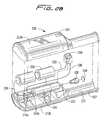
- FIG. 1is a perspective view of a first embodiment of a thrombectomy apparatus of the present invention
- FIG. 1Ais a perspective view of an alternate embodiment of the apparatus
- FIG. 2is an exploded view of the proximal portion of the thrombectomy apparatus of FIG. 1 ;
- FIG. 2Ais a perspective view of one embodiment of the motor housing attachable to the thrombectomy wire;
- FIG. 2Bis an exploded view of the motor housing of FIG. 1 showing the components for operatively connecting the motor to the thrombectomy wire;
- FIG. 2Cis a side view in partial cross-section of the coupler of FIG. 2B ;
- FIG. 2Dis a perspective view of the coupler of FIG. 2C ;
- FIG. 2Eis a side view in partial cross section illustrating the connection of the internal components of the motor housing
- FIG. 2Fis a side view showing the wire operatively connected to the motor shaft by the coupler of FIG. 2C ;
- FIG. 3is a side view in partial cross-section of the apparatus of FIG. 1 ;
- FIG. 3Ais longitudinal cross-sectional view taken along line 3 A- 3 A of FIG. 1 ;
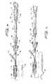
- FIG. 4is a side view of the apparatus of FIG. 1 showing the rotational wire in a non-linear position corresponding to a position exposed from the introducer sheath;
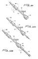
- FIG. 4Ais an enlarged view of the distal portion of one embodiment of the thrombectomy wire having a sinuous configuration
- FIG. 4Bis an enlarged view of the distal portion of an alternate embodiment of the thrombectomy wire having a J-tip configuration
- FIG. 5is a longitudinal cross-sectional view of the distal portion of the thrombectomy wire of the apparatus of FIG. 1 ;
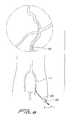
- FIG. 6is an anatomical view showing select cerebral arteries
- FIG. 7is a front anatomical view showing select cerebral arteries, including the circle of Willis;
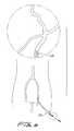
- FIG. 8illustrates insertion of a guide catheter through the femoral artery and into the cerebral artery over a tracking guidewire
- FIG. 9is a view similar to FIG. 8 illustrating withdrawal of the tracking guidewire
- FIG. 9Ais a perspective view illustrating attachment of the RHV to the introducer catheter
- FIG. 10illustrates insertion of the RHV and introducer catheter through the guide catheter and into the circle of Willis
- FIG. 10Ais a perspective view illustrating insertion of the introducer sheath into the RHV
- FIG. 10Bis a perspective view illustrating attachment of the connector tube to the introducer sheath
- FIG. 10Cis a perspective view of another introducer catheter
- FIG. 10Dis a side view showing attachment of the RHV and introducer catheter of FIG. 10C ;
- FIG. 11illustrates insertion of the thrombectomy wire of FIG. 1 into the RHV and through the introducer catheter, and continued advancement of the wire from the introducer catheter so the distal portion of the wire is positioned in the circle of Willis;
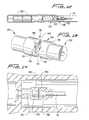
- FIG. 12is a side view in partial cross section similar to FIG. 2E showing an alternate embodiment of a coupler for coupling the thrombectomy wire to the motor;
- FIG. 13is a perspective view of the coupler of FIG. 12 ;
- FIG. 14is a cross-sectional view of the coupler of FIG. 13 shown within the motor housing coupling the motor shaft to the thrombectomy wire;
- FIG. 15is a perspective view of an alternate embodiment of the coupler for coupling the thrombectomy wire to the motor;
- FIG. 16is a front view of the housing of FIG. 15 for receiving the motor shaft.
- FIG. 17is a cross-sectional view of the coupler of FIG. 15 shown within the motor housing coupling the motor shaft to the thrombectomy wire.
- FIG. 1illustrates a first embodiment of the thrombectomy apparatus of the present invention.
- the thrombectomy apparatus of FIG. 1is designated generally by reference numeral 10 .
- the apparatusincludes a motor housing 12 , a rotational thrombectomy wire 30 , a rotating hemostatic valve (RHV) 40 , an introducer sheath 60 and a telescoping tube or tubular connector 80 .
- the RHV 40is connectable to an introducer catheter 100 discussed below in conjunction with the method of use.
- the introducer sheath 60is insertable into the RHV 40 to facilitate insertion of the thrombectomy wire 30 through the introducer catheter 100 .
- the thrombectomy apparatus or assembly 10 disclosed hereinprovides a rotational thrombectomy wire as a separate unit from a catheter. That is, the thrombectomy wire 30 is provided as a separate unit insertable through the RHV 40 which has a distal end 52 connected to a proximal end of the introducer catheter 100 to access the surgical site.
- the introducer sheath 60aids insertion of the thrombectomy wire 30 into the RHV 40 and through the introducer catheter 100 , with the walls of the introducer sheath 60 maintaining the non-linear distal end of the wire 30 in a substantially straightened (substantially linear) configuration as it enters the RHV 40 .
- the thrombectomy wire 30 of the present inventioncan be slid within the introducer sheath 60 and introducer catheter 100 prior to connection to the motor, if desired. This can aid introduction and manipulation of the wire 30 since it is less cumbersome and of lighter weight than if the motor housing 12 was attached during manipulation of the wire.
- the wire 30could be attached to the motor housing 12 prior to insertion through the introducer sheath 60 , RHV 40 and the introducer catheter 100 and thus the wire 30 would be slidable within the introducer sheath 60 (and introducer catheter 100 ) with the motor housing 12 attached.
- the motor housing 12can be attached to the wire at a desired time prior to or during the procedure.
- the motor housing 12which also forms a handle portion, has two identical housing halves 13 a , 13 b .
- a motor 14is seated within recess 14 a of housing half 13 a and the opposing recess of housing half 13 b and has a motor drive shaft 15 extending therefrom.
- Tabs 15 b( FIG. 3 ) help secure the motor 14 within the housing 12 .
- a gear reducer(not shown) could optionally be provided to reduce by way of example the rotational speed of the motor 52 from 15,000 rpm to 1500 rpm, 750 rpm, 150 rpm, etc.
- One or more batteries 16such as a 3 Volt battery, is positioned in recess 17 a of housing half 13 a and the opposing recess of housing half 13 b for powering the motor 14 .
- the battery(s) 16can be contained within a compartment in the housing 12 accessible by removing a battery door.
- the motor drive shaft 15connects to a proximal end of the thrombectomy wire 30 by various couplings, such as for example a snap fit wherein cap 31 is frictionally fit within the lumen 15 a of the motor drive shaft 15 .
- a printed circuit boardcan also be provided within the housing 30 and is designated by reference numeral 18 .
- Motor housing 12includes a distal tubular portion 22 having a tab in the form of a ring 24 which fits within a groove in the tube connector 80 , best shown in FIG. 3 to connect the motor housing 12 to tube connector 80 described below.
- Switch 19extends though recess 21 in housing half 13 a and in a corresponding recess in housing half 13 b .
- a potentiometer(not shown) can optionally be wired to the motor to enable dialing the motor speed up or down to adjust the rotational speed of the thrombectomy wire 30 to adjust for various procedures and/or clot locations and sizes.
- the potentiometeris used as a two terminal variable resistor, i.e. a rheostat, by not connecting the third terminal. In this manner, in the initial position, the motor speed is at the desired minimum and rotation of a knob (or in alternate embodiments sliding of a knob) progressively increases the motor speed.
- the on/off switch 19 extending from the housing 12is electrically connected to the motor 15 to turn on the motor 15 to activate the apparatus, i.e. rotate the wire 30 .
- rotating hemostatic valve (RHV) 40is connectable to an introducer catheter 100 (see FIG. 9A ).
- a conventional introducer cathetercan be utilized or alternatively a specially designed catheter for use with the apparatus of the present invention.
- the RHV 40is rotatable with respect to the catheter 100 to alter the orientation of the side arm 56 .
- Side arm 56extends from the tubular portion 46 and has a port 57 for introduction of fluids and/or application of vacuum as described below.
- Luer lockis provided at the distal end 52 of RHV 40 to connect to the introducer catheter as threads 51 a of rotation knob 51 threadingly engage proximal threads of the introducer catheter 100 .
- Tube extension 48fits within the lumen of the introducer catheter 100 when attached. Washers 49 a , 49 b help to provide a seal against fluid flow.
- Tubular portion 46 of RHV 40includes a lumen 55 extending therethrough to slidably receive the tubular portion 62 of the introducer sheath 60 .
- Proximal cap 58 at proximal end 54has internal threads 59 to threadingly attach to external proximal threads 47 for attachment of the cap 58 to the RHV 40 .
- a crush ring 43 and distal ring 44are seated within the internal lumen 55 of the tubular portion 46 .
- a proximal seal 45can also be provided.
- Flange 46 a on the proximal end 54 of RHV 40interacts with lip 58 a of cap 58 to allow loosening of cap 58 to release introducer sheath 60 without cap 58 detaching from RHV 40 .
- Side arm 56 of RHV 40has a lumen 53 in fluid communication with lumen 55 of tubular portion 46 .
- Fluids such as imaging dyecan be injected through the arm 56 , flowing through the lumens 53 and 55 , i.e. through the space between the outer wall of the introducer sheath 60 and the inner wall of lumen 55 and then through the space between the thrombectomy wire 30 the inner wall of the introducer catheter 100 and, exiting a distal opening 103 ( FIG. 10 ) in the introducer catheter 100 to flow into the vessel.
- This imaging dyecan be used to provide an indication that fluid flow has resumed in the vessel.
- the side arm 56can also be used for vacuum to suction particles detached from the vessel by the rotational wire 30 .
- the particleswould flow into the distal opening 103 of the introducer catheter 100 and through the space between the wire 30 and the inner wall of the introducer catheter 100 , then exiting through lumen 53 and port 57 into a suction tube (not shown).
- guide catheter 150 discussed in conjunction with the method of usecan also have a side arm for injection of fluid (see e.g., side arm 152 of FIG. 8 ).
- the RHV 40 ′does not have a side arm.
- a guide catheter with a side armcan be used for injection and suction.
- the componentsare identical to the components of FIG. 1 and for convenience, the corresponding components are labeled with “prime” designations e.g., rotational knob 51 ′, cap 58 ′, introducer sheath 60 ′, connector tube 80 ′ and locking cap 83 ′.
- the tubular portion 62 of introducer sheath 60extends through the lumen 55 of RHV 40 and terminates either within RHV 40 or at a proximal portion of the lumen of the introducer catheter 100 .
- the tubular portion 62preferably has a stiffness greater than the stiffness of the thrombectomy wire 30 to maintain the wire 30 in a straightened position during passage of wire 30 into the RHV 40 for subsequent passage through the lumen of the introducer catheter 100 to the surgical site.
- Proximal end 65 of introducer sheath 60is attachable to connector tube 80 .
- the enlarged proximal end 65has a threaded flange 67 as shown in FIG. 3A to threadingly engage the internal threads 85 on the distal cylindrical locking cap 83 at the distal end 82 of tubular connector 80 .
- a valvecan be provided within the distal end 82 of the connector tube 80 in addition or instead of a valve in a proximal end 65 of the introducer sheath 60 to seal escape of fluid to improve the vacuum through the side arm 56 .
- the tube 80 and introducer sheath 60can alternatively be provided as one unit, attached together and positioned over the thrombectomy wire 30 .
- the wire 30is inserted through the introducer sheath 60 and manipulated through the introducer catheter 100 to the surgical site. Once positioned, the connector tube 80 is then threadingly attached at the distal end 82 to the introducer sheath 60 as noted above and at a proximal end 84 to the motor housing 12 .
- the connector tube 80can be positioned over the wire 30 prior to insertion of the wire 30 through introducer sheath 60 or after insertion through the sheath 60 .
- the wire 30can be packaged with the sheath 60 and the tube 80 positioned thereover, or packaged apart from the sheath 60 and tube 80 .
- Proximal end 84 of connector tube 80is configured for attachment to the motor housing 12 by an external ring 24 on tip 22 of motor housing 12 . Ring 24 is seated within an internal groove of connector tube 80 , as shown in FIG. 3 , to provide a snap fit. Other types of attachment are also contemplated.
- the proximal end of the wire 30is attached to the drive shaft 15 of the motor 14 .
- end cap 31 of wire 30is snap fit within opening 15 a in motor shaft 15 .
- Other ways to attach the wire 30 and motor shaft 15are also contemplated such as a bayonet mount for example.
- the housingcan be detached, sterilized and reused after recharging of the battery or replacing the battery.
- the proximal end of wire 30after insertion to the surgical site or prior to insertion, can be attached at a proximal end to a coupler tube which is connected to a gear reducer.
- the connection of the motor and thrombectomy wirecan be a friction fit, a magnetic coupling or a twist connect, e.g. a bayonet connection, by way of example, such as that shown in co-pending patent application Ser. No. 13/095,329, filed Apr. 27, 2011, the entire contents of which are incorporated herein by reference.
- FIGS. 2A-2Fshow an alternative mechanism for operatively connecting the thrombectomy wire and motor.
- Motor housing 210is composed of two housing halves 212 a , 212 b which form the handle of the apparatus. Seated within the recess 213 in motor housing 210 is motor 214 electrically connected to two batteries 216 .
- Switch 218extends through opening 220 in motor housing 210 for access by the user. Attached to motor shaft 222 , which extends distally from motor 214 , is magnetic coupler 230 for magnetic coupling of the thrombectomy wire to the motor housing 210 .
- Electrical wire 226electrically connects switch 218 to post 214 a of motor 214 .
- Wire 229connects the switch 218 to the positive terminal of battery 216 and wire 228 connects the negative terminal of battery 216 to motor post 214 b.
- the magnetic couplerincludes a tube or housing 230 , preferably made of PVC, although other materials are also contemplated.
- Tube 230has a proximal portion 234 which receives motor shaft 222 and a distal portion 236 .
- a first magnet 242is positioned in the distal portion 236 of the tube 230 , and due to its transverse dimension being larger than the transverse dimension of tube 230 , forces the tube 230 to flare outwardly into flared portion 233 , thereby providing a tight frictional fit.
- a disc 240which can be made of a polymeric or of other material, but is preferably in the form of a Latex sheet, is provided over the distal edge 238 of tube 230 to maintain the first magnet 242 within the tube 230 .
- the disc 240functions as a clutch for torque transfer from the motor 214 to the thrombectomy wire 30 .
- the motor shaft 222extending distally from motor 214 , extends into the proximal end of the tube 226 and is frictionally engaged thereto.
- a second magnetis contained in housing 246 which is attached to the proximal end of the thrombectomy wire 30 by gluing, overmolding, or other attachment methods.
- the thrombectomy wire 30is inserted into the reduced diameter portion 217 of motor housing 214 until the magnetic attraction between the second magnet and first magnet 242 maintains a magnetic connection.
- motor shaft 222rotates to thereby rotate magnetically coupled thrombectomy wire 30 .
- Note the torqueis transferred to the wire 30 due to the disc 240 functioning as a clutch.
- the disc 240can be in the form of a polymeric sheet.
- the sheetcan be designed to wear off after a period of time, thus wearing away the clutch, resulting in the loss of the ability to transfer torque. In this way, over-use of the apparatus can be prevented, and the apparatus can advantageously be designed for one time use in a single procedure.
- housing 330has a proximal portion 334 which frictionally receives the motor shaft 222 and a distal portion 336 .
- the distalmost edge 338is in a wavy pattern forming a toothed design.
- a first magnet 340is positioned in the distal portion 336 , recessed from the distalmost edge 338 .
- a second housing 350is attached to the proximal end of the thrombectomy wire 30 .
- the second housing 350has a distal portion 352 to frictionally receive the wire 30 and a proximal portion 354 .
- the proximalmost edge 358is in a wavy pattern forming a toothed design configured to mate with the toothed design at the distalmost edge 338 of housing 330 .
- a second magnet 360is positioned in the proximal portion 354 , recessed distally from the proximal most edge 358 . In this manner, first and second magnets 340 , 360 do not come into contact but provide an attractive coupling force to attach the wire 30 and motor shaft 222 of motor 214 .
- the first plurality of teeth 337 of first housing 330intermesh with the second plurality of teeth 357 of the second housing 350 so that upon rotation of the motor shaft 222 , the coupled housings 330 , 350 rotate. Due to the interaction of the teeth 337 of housing 330 with the teeth 357 of housing 350 , rotation of housing 330 causes housing 350 to rotate which thereby rotates the wire 30 attached to housing 350 .
- These housings 330 , 350operate as a clutch mechanism. That is, if during use, the torque of the motor shaft 222 exceeds a preset value, indicating for example that the wire is caught on material in the vessel, the teeth 337 , 357 of the housings 330 , 350 , slip such that housing 330 rotation no longer rotates housing 350 .
- this coupling designforms a clutch which when the torque of the motor shaft exceeds a predetermined value, the teeth slip so the teeth are no longer operably intermeshed.
- the torsional load at which the coupling slipsdepends on the friction between the teeth, thereby relying solely on the coefficient of friction of the housing materials and the angle/geometry of the teeth. Slippage occurs when torsional force is greater than frictional force and the magnetic force holding the housings together.
- the housings 430 , 450are similar to housings 330 , 350 and have distalmost and proximal most edges 438 , 458 , respectively, which are in a wavy pattern forming teeth 437 , 457 , which intermesh to rotate the second housing 450 as the first housing 430 is rotated by the rotating motor shaft 222 .
- spherical magnetsare provided within a gap in the housings 430 , 450 to allow movement, e.g., rolling, of the magnets.
- housing 430has a proximal portion 434 which receives the motor shaft 222 and a distal portion 436 .
- the distalmost edge 438is in a wavy pattern forming a toothed design.
- a first substantially spherical magnet 440is positioned in the distal portion 436 in an internal cavity 433 , recessed proximally from the distalmost edge 438 .
- the internal cavity 433forms a gap 435 proximal of magnet 440 .
- a plug 439is press fit in a proximal opening of the cavity 433 to secure the magnet 440 within the cavity 433 .
- the motor shaft 222can be mounted in a proximal opening in plug 439 such as by an interference fit.
- the magnet 440can move within the gap 435 . In this manner, as the housing 430 rotates, the magnet 440 does not rotate with the housing 430 and can float or roll within the gap 435 .
- a second housing 450is attached to the proximal end of the thrombectomy wire 30 .
- the second housing 450has a distal portion 454 to frictionally receive the wire 30 and a proximal portion 452 .
- the proximal most edge 458is in a wavy pattern forming a toothed design configured to mate with the toothed design at the distalmost edge 438 of housing 430 .
- a second substantially spherical magnet 460is positioned in the proximal portion 452 , recessed distally from the proximal most edge 458 .
- the housing 450has an internal cavity 453 forming a gap 455 distal of magnet 460 .
- a plug 459is press fit in a proximal opening of the cavity 453 to secure the magnet 460 within the cavity 453 .
- the thrombectomy wire 30can be mounted in a distal opening of plug 459 such as by an interference fit.
- the magnet 460can move within the gap 455 . In this manner, as the housing 450 rotates, the magnet 460 does not rotate with the housing and can float or roll within the gap 455 .
- the first and second magnets 440 , 460do not come into contact but provide an attractive coupling force to attach the wire 30 and motor 214 .
- the placement of the magnets in recessed pocketshas the advantages described above.
- the teeth 437 , 457 , of the respective housings 430 , 450intermesh so that upon rotation of the motor shaft 222 , the attached housing 430 rotates. Due to the interaction of the teeth 437 of housing 430 with the teeth 457 of housing 450 , rotation of housing 430 causes housing 450 to rotate which thereby rotates the wire 30 attached to housing 450 . During such rotation, magnets 440 , 460 can move, e.g., float or roll, within the gaps 433 , 453 of housings 430 , 450 , respectively. The gaps can be sufficiently large relative to the magnets to enable the magnets to freely float therein, i.e., not only move axially but move in three dimensions.
- housings 430 , 450operate as a clutch mechanism. If during use, the torque of the motor shaft exceeds a preset value, indicating that the wire is caught on a vessel, the teeth 437 , 457 of the housings 430 , 450 , respectively, slip such that housing 430 rotation no longer rotates housing 450 . Due to the spacing of magnets 440 , 460 from each other, as a result of their mounting within recess of the respective housing 430 , 450 , the force at which the housings (clutch) slip is entirely dependent on the interaction of the teeth 437 , 457 . That is, as in the embodiment of FIGS.
- this coupling designforms a clutch which when the torque of the motor shaft exceeds a predetermined value, it causes the teeth 437 , 457 to slip so the teeth are no longer operably intermeshed.
- the torsional load at which the coupling slipsdepends on the friction between the teeth, thereby relying solely on the coefficient of friction of the housing materials and the angle/geometry of the teeth. Slippage occurs when torsional force is greater than frictional force and the magnetic force holding the housings together. If the magnets were in direct contact, the frictional engagement of the magnets in addition to the interaction of the teeth would affect the slippage point.
- the designis simplified. The press-fit of the magnets into the recessed pockets also facilitates manufacture.
- step of operatively coupling the thrombectomy wire to the motor housing 210 using any of the foregoing coupling embodimentscan occur prior to the step of inserting the thrombectomy wire through the introducer sheath and catheter.
- step of operatively coupling the thrombectomy wire to the motor housing 210 using any of the foregoing embodimentscan occur subsequent to the step of inserting the thrombectomy wire through the introducer sheath and catheter.
- FIG. 5illustrates the thrombectomy wire 30 of the present invention.
- the wire 30has a distal coiled tip 91 .
- the distal coiled tip (and underlying cable)is angled with respect to the longitudinal axis.
- FIG. 4Ashows the wire of FIG. 5 forming a sinuous shape.
- FIG. 4Ban alternative embodiment of the wire is illustrated, wherein the wire 130 forms a J-tip which creates a standing wave upon rotation. In the J-tip configuration, due to the angle, when the wire is rotated by the motor at sufficient speed at least one vibrational node is formed. Details of this creation of a standing wave are described in U.S. Pat. No. 6,090,118, the entire contents of which are incorporated herein by reference.
- the wire 30forms a substantially sinuous shape, resembling a sine curve. More specifically, wire 30 of FIG. 4A has a substantially linear portion extending through most of its length, from a proximal region, through an intermediate region, to distal region 36 . At the distal region 36 , wire 30 has a sinuous shape in that as shown it has a first arcuate region 33 facing a first direction (upwardly as viewed in the orientation of FIG. 4A ) and a second arcuate region 35 , spaced longitudinally from the first arcuate region 33 , facing a second opposite direction (downwardly as viewed in the orientation of FIG. 4A ).
- This angled (non-linear) distal portionincludes a coiled portion with a covering material to block the interstices of the coil as discussed below.
- the amplitude of the proximal wave (at region 33 )is smaller than the amplitude of the distal wave (at region 35 ), facilitating movement in and out of the catheter.
- the curved regions of the wire 30are compressed so the distal region 36 is contained in a substantially straight or linear non-deployed configuration.
- the introducer catheter 100is retracted by proximal axial movement (see the arrow of FIG. 4 ), or the wire is advanced with respect to the introducer catheter 100 or the wire 30 and catheter 100 are both moved in the respective distal and proximal directions, the distal region 36 of the wire 30 is exposed to enable the wire 30 to return to its non-linear substantially sinuous configuration shown in FIG. 4A (and FIG. 4 ) for rotation about its longitudinal axis within the lumen of the vessel.
- the wire 30is advanced within the introducer catheter 100 which is attached at its proximal end to the distal end of the RHV 40 .
- the wire 30 and introducer catheterare relatively moved to expose the wire 30 to assume its non-linear shape for motorized rotational movement to break up thrombotic material on the vessel wall.
- a J-tip wiresuch as wire 130
- the wire 130can be rotated within the introducer catheter to re-orient the wire 130 .
- the flexible tubular portion 62 of the introducer sheath 60can optionally contain one or more braided wires embedded in the wall to increase the stiffness. Such braided wires would preferably extend the length of the sheath.
- the memorized configurationis sinuous or s-shaped as in FIG. 4A .
- the wireIn the state within the introducer catheter 100 , the wire is in a substantially linear configuration. This state is used for delivering the wire to the surgical site. When the wire is exposed to warmer body temperature, the tip transforms to its austenitic state, assuming the s-shaped memorized configuration.
- the coiled tip of the wirecan be compressed within the wall of the introducer catheter and when released, assumes its shape memorized non-linear shape.
- the coiled tipcan alternatively be a radiopaque coil/polymer pre-shaped to an “S”.
- Wire 30has a core 32 having a proximal portion 34 (see FIG. 2 ) and a distal portion 37 . Transition region 38 of core 32 is tapered distally so that the diameter of the distal portion 37 of core 32 is less than the diameter of the proximal portion 34 .
- a uniform diameter portion 37 aextends distal of tapered portion 37 .
- the tapercan be formed by removing a coating, such as a PTFE coating, placed over the core 32 and a grinding of the core 32 .
- the core 32is a solid material made of a nickel titanium alloy, although other materials are also contemplated.
- the core 32can also be formed from a hypotube with a tapered body attached, e.g. welded, to the distal end of the hypotube.
- the core 32is connected to a cable 90 .
- the cable 90can be formed of a plurality of wires twisted together such as a 1 ⁇ 19 wire for example.
- the twisted wirescan be surrounded by additional wires or a sheath.
- the core 32is tapered to accommodate connection to cable 90 .
- Hypotube 92is placed over the distalmost end of the core 32 (the uniform diameter portion 37 a ) and the proximal most end of the cable 90 and is attached thereto by a number of methods, including but not limited to, laser welding, soldering or crimping.
- the hypotube 92thereby forms a coupler for joining the core 32 and cable 90 as these components are positioned within the hypotube 92 .
- the hypotubecan have a diameter of about 0.010 inches, although other dimensions are contemplated.
- the cable 90in one embodiment has a variable stiffness such that the proximal portion 94 is stiffer, e.g., has a tighter braid, than a distal portion 96 to increase the flexibility of the distal portion 96 .
- the cable 90is of uniform stiffness.
- the cable 90can be of substantially uniform diameter.
- Various covering materials, e.g., coating, jackets and/or shrink wraps,can be used as an alternative or in addition to vary the stiffness of the cable 90 .
- a torque tube 97is positioned over the cable 90 .
- the torque tube 97extends from a tapered region of the core 32 , terminating at the distal coil 91 .
- the torque tube 97can be soldered at (proximal) end 97 a to the core 32 and at distal end 97 b to the cable 90 .
- the torque tube 97can also be attached, e.g., soldered or laser welded, to a proximal end of the coil.
- a polymer coating(s) and/or jacket(s)can be placed over the torque tube 97 to cover the interstices in the cable 90 and provide a smooth surface.
- a PTFE shrink wrap tubing 98is placed over the torque tube 97 and over a portion of the core 32 , preferably extending over the tapered transition region 38 of core 32 to terminate at a proximal end adjacent the uniform diameter region of the core 32 .
- the shrink wrap 98terminates at the end where the torque tube 97 terminates.
- Coiled tip 91is positioned over a distal portion of the cable 90 , and preferably over the distal tip.
- the coil tip 91in one embodiment is composed of a soft and malleable material such as platinum and has a uniform pitch and diameter.
- the distalmost tip of the cable 90can have a laser welded ball to which the coil 91 is welded to enhance retention of the coil 91 and cable 90 .
- the coiled tip regionhas a substantially sinuous configuration. In an alternate embodiment, the coiled tip region has a J-tip configuration, as shown for example in FIG. 4B .
- the coiled tip regioncan alternatively have a substantially linear configuration in the deployed/uncovered position.
- a coveringsuch as a jacket, shrink wrap or coating covers the coil 91 .
- a polyamidesuch as a nylon or Pebax covering 99 is heat fused over the coil 91 , to melt into the interstices.
- a heat shrink tubing 99 asuch as FEP, is placed over the heat fused nylon coating. The covering 99 , and heat shrink tubing 99 a , terminate adjacent a distal end of the torque tube 97 and adjacent a distal end of the shrink wrap 98 .
- the components of wire 30can have the approximate dimensions set forth in the table below. It should be understood that these dimensions are being provided by way of example as other dimensions are also contemplated. These are also approximate values.
- the covering materiale.g. coating, jackets, and or shrink wraps, helps to prevent bending or knotting of the wire which could otherwise occur in native vessels.
- the coveringalso increases the torsional strength of the wire and also strengthens the wire to accommodate spasms occurring in the vessel.
- the coatingalso blocks the interstices of the coil 91 to provide a less abrasive surface.
- the various coating and/or jackets and/or shrink wrapcan be made of PET, Teflon, Pebax, polyurethane or other polymeric materials. The material helps to prevent the native vessel from being caught in the coil 90 and reduces vessel spasms.
- thrombectomy apparatus 10The use of the thrombectomy apparatus 10 will now be described. The use, by way of example, is shown and described with respect to the embodiment of FIG. 1 with the sinuous tip of FIG. 4 , it being understood that the wire embodiment of FIG. 4B would be utilized in a similar manner. It is also shown for use in the cerebral arteries but use in other vessels is also contemplated.
- An access sheath(not shown) is inserted into the vessel and then a guidewire, e.g. 0.035 or 0.038 inches in diameter, and a guide catheter 150 are inserted through the sheath and advanced through the vasculature.
- the guidewireis removed and a smaller diameter guidewire G, e.g. 0.014 inch diameter, and the introducer catheter 100 , are inserted through the guide catheter 150 and access sheath with the guidewire G in the femoral artery F and located via imaging.
- the introducer catheter 100is advanced to the desired site through the vascular system into the cerebral arteries A, for example through the Circle of Willis C (see FIGS. 6 , 7 and 8 ). Once at the site, the guidewire G is withdrawn as shown in FIG. 9 .
- the introducer catheter 100is preferably inserted with the RHV 40 attached. That is, the tubular portion 46 of the RHV 40 is inserted through the introducer catheter 100 (see FIG. 10 ) and attached thereto by rotation of cap 51 as shown in FIG. 9A .
- RHV 40is attached to thread 124 of the winged luer fitting of introducer catheter 120 by rotation of cap 51 and/or winged handle 122 .
- the RHV 40instead of the RHV 40 attached prior to introduction of the introducer catheter 100 through the guide catheter 150 , it can be attached after introduction of catheter 100 through guide catheter 150 .
- the introducer sheath 60is inserted through the RHV 40 , and attached to the RHV 40 by rotation of cap 58 as shown in FIG. 10A .
- the thrombectomy wire 30is inserted through the lumen of the introducer sheath 60 , through the lumen of the RHV 40 and into the lumen of the introducer catheter 100 .
- the introducer catheter 100extends from the guide catheter 150 as shown in FIG. 10 , but the wire 30 remains inside the introducer catheter 100 .
- the distal end of the wire 30is then exposed from the introducer catheter 100 at the target surgical site by relative movement of the wire 30 and introducer sheath 100 .
- the wire 30can be attached to the motor drive shaft 15 at this point or can be attached before exposed or at any other time in the procedure such as prior to insertion of the wire 30 through the introducer sheath 60 . Attachment is achieved by connection of the connector tube 80 to the introducer sheath 60 (see FIG. 10B ) and attachment of the proximal end of the connector 80 to the motor housing 12 or by other methods, such as a magnetic coupling as described above.
- the wire 30extends through the connector tube and attachment of the wire 30 (which extends through connector 80 ) to the motor drive shaft 15 .
- the connector tube 80can be connected to the introducer sheath 60 prior to attachment to the motor housing 12 , or alternatively connected after the wire 30 is at the surgical site and exposed from the introducers sheath.
- the alternate embodiments described herein for coupling the wire to the motor shaftcould also be utilized.
- switch 19 on housing 12is actuated to turn on the motor thereby causing wire 30 to rotate about its longitudinal axis to break up/macerate thrombus.
- the macerated particlescan be removed by suction through side arm 56 of RHV 40 as the particles travel in the space between wire 30 and introducer catheter 100 and RHV 40 .
- the introducer catheter 100can optionally have a side port(s) and/or the guide catheter 150 can optionally have a side port(s) such as side port 152 for aspirating the small macerated particles in addition to or alternative to side arm 56 of RHV 40 .
- the delivery sheathcan include a balloon to block blood flow and allow aspiration in the blocked space.
Landscapes
- Health & Medical Sciences (AREA)
- Surgery (AREA)
- Life Sciences & Earth Sciences (AREA)
- Biomedical Technology (AREA)
- Nuclear Medicine, Radiotherapy & Molecular Imaging (AREA)
- Engineering & Computer Science (AREA)
- Vascular Medicine (AREA)
- Heart & Thoracic Surgery (AREA)
- Medical Informatics (AREA)
- Molecular Biology (AREA)
- Animal Behavior & Ethology (AREA)
- General Health & Medical Sciences (AREA)
- Public Health (AREA)
- Veterinary Medicine (AREA)
- Surgical Instruments (AREA)
Abstract
Description
| APPROXIMATE OUTER | APPROXIMATE | |
| COMPONENT | LENGTH | |
| Core | ||
| 32 | .016 inches | 139.5 cm |
| (proximal non | ||
| tapered portion) | ||
| Core tapered portion | .016 inches to .0095 inches | 4.35 inches |
| .016 inches | 3.0 | |
| Torque tube | ||
| 97 | .013 inches | 8.0 inches |
| Shrink | .014 inches | 10.35 |
| Cable | ||
| 90 | .010 inches | 8.2 inches |
Claims (17)
Priority Applications (5)
| Application Number | Priority Date | Filing Date | Title |
|---|---|---|---|
| US13/456,555US9023070B2 (en) | 2010-05-13 | 2012-04-26 | Rotational thrombectomy wire coupler |
| CA2776090ACA2776090A1 (en) | 2011-05-16 | 2012-05-04 | Rotational thrombectomy wire coupler |
| EP12167819.7AEP2524661B1 (en) | 2011-05-16 | 2012-05-14 | Rotational thrombectomy wire coupler |
| US14/696,418US9795406B2 (en) | 2010-05-13 | 2015-04-25 | Rotational thrombectomy wire |
| US15/727,519US20180028223A1 (en) | 2010-05-13 | 2017-10-06 | Rotational thrombectomy wire |
Applications Claiming Priority (6)
| Application Number | Priority Date | Filing Date | Title |
|---|---|---|---|
| US33441210P | 2010-05-13 | 2010-05-13 | |
| US201161431169P | 2011-01-10 | 2011-01-10 | |
| US13/095,329US8663259B2 (en) | 2010-05-13 | 2011-04-27 | Rotational thrombectomy wire |
| US201161486425P | 2011-05-16 | 2011-05-16 | |
| US13/303,339US8764779B2 (en) | 2010-05-13 | 2011-11-23 | Rotational thrombectomy wire |
| US13/456,555US9023070B2 (en) | 2010-05-13 | 2012-04-26 | Rotational thrombectomy wire coupler |
Related Parent Applications (1)
| Application Number | Title | Priority Date | Filing Date |
|---|---|---|---|
| US13/303,339Continuation-In-PartUS8764779B2 (en) | 2010-05-13 | 2011-11-23 | Rotational thrombectomy wire |
Related Child Applications (1)
| Application Number | Title | Priority Date | Filing Date |
|---|---|---|---|
| US14/696,418Continuation-In-PartUS9795406B2 (en) | 2010-05-13 | 2015-04-25 | Rotational thrombectomy wire |
Publications (2)
| Publication Number | Publication Date |
|---|---|
| US20120239066A1 US20120239066A1 (en) | 2012-09-20 |
| US9023070B2true US9023070B2 (en) | 2015-05-05 |
Family
ID=46829064
Family Applications (1)
| Application Number | Title | Priority Date | Filing Date |
|---|---|---|---|
| US13/456,555Active2032-11-24US9023070B2 (en) | 2010-05-13 | 2012-04-26 | Rotational thrombectomy wire coupler |
Country Status (1)
| Country | Link |
|---|---|
| US (1) | US9023070B2 (en) |
Cited By (119)
| Publication number | Priority date | Publication date | Assignee | Title |
|---|---|---|---|---|
| US20150257783A1 (en)* | 2010-05-13 | 2015-09-17 | Rex Medical, L.P. | Rotational thrombectomy wire |
| US20170296220A1 (en)* | 2010-05-13 | 2017-10-19 | Rex Medical, L.P. | Rotational thrombectomy wire |
| USD802769S1 (en) | 2016-05-16 | 2017-11-14 | Teleflex Medical Incorporated | Thrombectomy handle assembly |
| US20170348019A1 (en)* | 2016-06-06 | 2017-12-07 | Terumo Kabushiki Kaisha | Device handle for a medical device |
| US10064645B2 (en) | 2010-05-13 | 2018-09-04 | Rex Medical, L.P. | Rotational thrombectomy wire |
| US10179224B2 (en) | 2016-02-24 | 2019-01-15 | Incept, Llc | Enhanced flexibility neurovascular catheter with tensile support |
| US10213582B2 (en) | 2013-12-23 | 2019-02-26 | Route 92 Medical, Inc. | Methods and systems for treatment of acute ischemic stroke |
| US10226263B2 (en) | 2015-12-23 | 2019-03-12 | Incuvate, Llc | Aspiration monitoring system and method |
| US10271869B2 (en) | 2014-03-01 | 2019-04-30 | Rex Medical, L.P. | Atherectomy device |
| US10307175B2 (en) | 2016-03-26 | 2019-06-04 | Rex Medical, L.P | Atherectomy device |
| US10433868B2 (en) | 2014-12-27 | 2019-10-08 | Rex Medical, L.P. | Artherectomy device |
| US10456555B2 (en) | 2015-02-04 | 2019-10-29 | Route 92 Medical, Inc. | Rapid aspiration thrombectomy system and method |
| US10463389B2 (en) | 2014-12-27 | 2019-11-05 | Rex Medical, L.P. | Atherectomy device |
| US10517627B2 (en) | 2012-04-09 | 2019-12-31 | Ethicon Llc | Switch arrangements for ultrasonic surgical instruments |
| US10561440B2 (en) | 2015-09-03 | 2020-02-18 | Vesatek, Llc | Systems and methods for manipulating medical devices |
| US10575892B2 (en) | 2015-12-31 | 2020-03-03 | Ethicon Llc | Adapter for electrical surgical instruments |
| US10595929B2 (en) | 2015-03-24 | 2020-03-24 | Ethicon Llc | Surgical instruments with firing system overload protection mechanisms |
| US10610286B2 (en) | 2015-09-30 | 2020-04-07 | Ethicon Llc | Techniques for circuit topologies for combined generator |
| US10639092B2 (en) | 2014-12-08 | 2020-05-05 | Ethicon Llc | Electrode configurations for surgical instruments |
| US10646269B2 (en) | 2016-04-29 | 2020-05-12 | Ethicon Llc | Non-linear jaw gap for electrosurgical instruments |
| US10653426B2 (en) | 2017-01-06 | 2020-05-19 | Incept, Llc | Thromboresistant coatings for aneurysm treatment devices |
| US10653434B1 (en) | 2018-05-01 | 2020-05-19 | Imperative Care, Inc. | Devices and methods for removing obstructive material from an intravascular site |
| US10688321B2 (en) | 2009-07-15 | 2020-06-23 | Ethicon Llc | Ultrasonic surgical instruments |
| US10709469B2 (en) | 2016-01-15 | 2020-07-14 | Ethicon Llc | Modular battery powered handheld surgical instrument with energy conservation techniques |
| US10716615B2 (en) | 2016-01-15 | 2020-07-21 | Ethicon Llc | Modular battery powered handheld surgical instrument with curved end effectors having asymmetric engagement between jaw and blade |
| US10729494B2 (en) | 2012-02-10 | 2020-08-04 | Ethicon Llc | Robotically controlled surgical instrument |
| US10765470B2 (en) | 2015-06-30 | 2020-09-08 | Ethicon Llc | Surgical system with user adaptable techniques employing simultaneous energy modalities based on tissue parameters |
| US10779879B2 (en) | 2014-03-18 | 2020-09-22 | Ethicon Llc | Detecting short circuits in electrosurgical medical devices |
| US10779845B2 (en) | 2012-06-29 | 2020-09-22 | Ethicon Llc | Ultrasonic surgical instruments with distally positioned transducers |
| US10835307B2 (en) | 2001-06-12 | 2020-11-17 | Ethicon Llc | Modular battery powered handheld surgical instrument containing elongated multi-layered shaft |
| US10856929B2 (en) | 2014-01-07 | 2020-12-08 | Ethicon Llc | Harvesting energy from a surgical generator |
| US10898256B2 (en) | 2015-06-30 | 2021-01-26 | Ethicon Llc | Surgical system with user adaptable techniques based on tissue impedance |
| US10912603B2 (en) | 2013-11-08 | 2021-02-09 | Ethicon Llc | Electrosurgical devices |
| US10912580B2 (en) | 2013-12-16 | 2021-02-09 | Ethicon Llc | Medical device |
| US10925659B2 (en) | 2013-09-13 | 2021-02-23 | Ethicon Llc | Electrosurgical (RF) medical instruments for cutting and coagulating tissue |
| US10952788B2 (en) | 2015-06-30 | 2021-03-23 | Ethicon Llc | Surgical instrument with user adaptable algorithms |
| US10966747B2 (en) | 2012-06-29 | 2021-04-06 | Ethicon Llc | Haptic feedback devices for surgical robot |
| US10987123B2 (en) | 2012-06-28 | 2021-04-27 | Ethicon Llc | Surgical instruments with articulating shafts |
| US10993763B2 (en) | 2012-06-29 | 2021-05-04 | Ethicon Llc | Lockout mechanism for use with robotic electrosurgical device |
| US11020133B2 (en) | 2017-01-10 | 2021-06-01 | Route 92 Medical, Inc. | Aspiration catheter systems and methods of use |
| US11051873B2 (en) | 2015-06-30 | 2021-07-06 | Cilag Gmbh International | Surgical system with user adaptable techniques employing multiple energy modalities based on tissue parameters |
| US11065019B1 (en) | 2015-02-04 | 2021-07-20 | Route 92 Medical, Inc. | Aspiration catheter systems and methods of use |
| US11065018B2 (en) | 2019-12-18 | 2021-07-20 | Imperative Care, Inc. | Methods and systems for advancing a catheter to a target site |
| US11090104B2 (en) | 2009-10-09 | 2021-08-17 | Cilag Gmbh International | Surgical generator for ultrasonic and electrosurgical devices |
| US11096752B2 (en) | 2012-06-29 | 2021-08-24 | Cilag Gmbh International | Closed feedback control for electrosurgical device |
| US11129670B2 (en) | 2016-01-15 | 2021-09-28 | Cilag Gmbh International | Modular battery powered handheld surgical instrument with selective application of energy based on button displacement, intensity, or local tissue characterization |
| US11129669B2 (en) | 2015-06-30 | 2021-09-28 | Cilag Gmbh International | Surgical system with user adaptable techniques based on tissue type |
| US11134859B2 (en) | 2019-10-15 | 2021-10-05 | Imperative Care, Inc. | Systems and methods for multivariate stroke detection |
| US11179173B2 (en) | 2012-10-22 | 2021-11-23 | Cilag Gmbh International | Surgical instrument |
| US11202670B2 (en) | 2016-02-22 | 2021-12-21 | Cilag Gmbh International | Method of manufacturing a flexible circuit electrode for electrosurgical instrument |
| US11207497B1 (en) | 2020-08-11 | 2021-12-28 | Imperative Care, Inc. | Catheter with enhanced tensile strength |
| US11224449B2 (en) | 2015-07-24 | 2022-01-18 | Route 92 Medical, Inc. | Anchoring delivery system and methods |
| US11229471B2 (en) | 2016-01-15 | 2022-01-25 | Cilag Gmbh International | Modular battery powered handheld surgical instrument with selective application of energy based on tissue characterization |
| US11229770B2 (en) | 2018-05-17 | 2022-01-25 | Route 92 Medical, Inc. | Aspiration catheter systems and methods of use |
| US11253292B2 (en) | 2015-09-13 | 2022-02-22 | Rex Medical, L.P. | Atherectomy device |
| US11311326B2 (en) | 2015-02-06 | 2022-04-26 | Cilag Gmbh International | Electrosurgical instrument with rotation and articulation mechanisms |
| US11324527B2 (en) | 2012-11-15 | 2022-05-10 | Cilag Gmbh International | Ultrasonic and electrosurgical devices |
| US11337747B2 (en) | 2014-04-15 | 2022-05-24 | Cilag Gmbh International | Software algorithms for electrosurgical instruments |
| US11344362B2 (en) | 2016-08-05 | 2022-05-31 | Cilag Gmbh International | Methods and systems for advanced harmonic energy |
| US11382642B2 (en) | 2010-02-11 | 2022-07-12 | Cilag Gmbh International | Rotatable cutting implements with friction reducing material for ultrasonic surgical instruments |
| US11395665B2 (en) | 2018-05-01 | 2022-07-26 | Incept, Llc | Devices and methods for removing obstructive material, from an intravascular site |
| US11399855B2 (en) | 2014-03-27 | 2022-08-02 | Cilag Gmbh International | Electrosurgical devices |
| US11413060B2 (en) | 2014-07-31 | 2022-08-16 | Cilag Gmbh International | Actuation mechanisms and load adjustment assemblies for surgical instruments |
| US11426191B2 (en) | 2012-06-29 | 2022-08-30 | Cilag Gmbh International | Ultrasonic surgical instruments with distally positioned jaw assemblies |
| US11439799B2 (en) | 2019-12-18 | 2022-09-13 | Imperative Care, Inc. | Split dilator aspiration system |
| US11452525B2 (en) | 2019-12-30 | 2022-09-27 | Cilag Gmbh International | Surgical instrument comprising an adjustment system |
| US11471582B2 (en) | 2018-07-06 | 2022-10-18 | Incept, Llc | Vacuum transfer tool for extendable catheter |
| US11471209B2 (en) | 2014-03-31 | 2022-10-18 | Cilag Gmbh International | Controlling impedance rise in electrosurgical medical devices |
| US11517335B2 (en) | 2018-07-06 | 2022-12-06 | Incept, Llc | Sealed neurovascular extendable catheter |
| US11553935B2 (en) | 2019-12-18 | 2023-01-17 | Imperative Care, Inc. | Sterile field clot capture module for use in thrombectomy system |
| US11565082B2 (en) | 2020-03-10 | 2023-01-31 | Imperative Care, Inc. | Enhanced flexibility neurovascular catheter |
| US11583306B2 (en) | 2012-06-29 | 2023-02-21 | Cilag Gmbh International | Surgical instruments with articulating shafts |
| US11589916B2 (en) | 2019-12-30 | 2023-02-28 | Cilag Gmbh International | Electrosurgical instruments with electrodes having variable energy densities |
| US11653945B2 (en) | 2007-02-05 | 2023-05-23 | Walk Vascular, Llc | Thrombectomy apparatus and method |
| US11660089B2 (en) | 2019-12-30 | 2023-05-30 | Cilag Gmbh International | Surgical instrument comprising a sensing system |
| US11666375B2 (en) | 2015-10-16 | 2023-06-06 | Cilag Gmbh International | Electrode wiping surgical device |
| US11678905B2 (en) | 2018-07-19 | 2023-06-20 | Walk Vascular, Llc | Systems and methods for removal of blood and thrombotic material |
| US11684412B2 (en) | 2019-12-30 | 2023-06-27 | Cilag Gmbh International | Surgical instrument with rotatable and articulatable surgical end effector |
| US11696776B2 (en) | 2019-12-30 | 2023-07-11 | Cilag Gmbh International | Articulatable surgical instrument |
| US11723716B2 (en) | 2019-12-30 | 2023-08-15 | Cilag Gmbh International | Electrosurgical instrument with variable control mechanisms |
| US11759251B2 (en) | 2019-12-30 | 2023-09-19 | Cilag Gmbh International | Control program adaptation based on device status and user input |
| US11766539B2 (en) | 2019-03-29 | 2023-09-26 | Incept, Llc | Enhanced flexibility neurovascular catheter |
| US11779329B2 (en) | 2019-12-30 | 2023-10-10 | Cilag Gmbh International | Surgical instrument comprising a flex circuit including a sensor system |
| US11779387B2 (en) | 2019-12-30 | 2023-10-10 | Cilag Gmbh International | Clamp arm jaw to minimize tissue sticking and improve tissue control |
| US11786291B2 (en) | 2019-12-30 | 2023-10-17 | Cilag Gmbh International | Deflectable support of RF energy electrode with respect to opposing ultrasonic blade |
| US11812957B2 (en) | 2019-12-30 | 2023-11-14 | Cilag Gmbh International | Surgical instrument comprising a signal interference resolution system |
| US11864820B2 (en) | 2016-05-03 | 2024-01-09 | Cilag Gmbh International | Medical device with a bilateral jaw configuration for nerve stimulation |
| US11871955B2 (en) | 2012-06-29 | 2024-01-16 | Cilag Gmbh International | Surgical instruments with articulating shafts |
| US11871944B2 (en) | 2011-08-05 | 2024-01-16 | Route 92 Medical, Inc. | Methods and systems for treatment of acute ischemic stroke |
| US11890491B2 (en) | 2008-08-06 | 2024-02-06 | Cilag Gmbh International | Devices and techniques for cutting and coagulating tissue |
| US11911063B2 (en) | 2019-12-30 | 2024-02-27 | Cilag Gmbh International | Techniques for detecting ultrasonic blade to electrode contact and reducing power to ultrasonic blade |
| US11937863B2 (en) | 2019-12-30 | 2024-03-26 | Cilag Gmbh International | Deflectable electrode with variable compression bias along the length of the deflectable electrode |
| US11937866B2 (en) | 2019-12-30 | 2024-03-26 | Cilag Gmbh International | Method for an electrosurgical procedure |
| US11944366B2 (en) | 2019-12-30 | 2024-04-02 | Cilag Gmbh International | Asymmetric segmented ultrasonic support pad for cooperative engagement with a movable RF electrode |
| US11950797B2 (en) | 2019-12-30 | 2024-04-09 | Cilag Gmbh International | Deflectable electrode with higher distal bias relative to proximal bias |
| US11980409B2 (en) | 2022-08-08 | 2024-05-14 | Crossfire Medical Inc | Segmental vascular ablation |
| US11986201B2 (en) | 2019-12-30 | 2024-05-21 | Cilag Gmbh International | Method for operating a surgical instrument |
| US11998230B2 (en) | 2016-11-29 | 2024-06-04 | Cilag Gmbh International | End effector control and calibration |
| US12023086B2 (en) | 2019-12-30 | 2024-07-02 | Cilag Gmbh International | Electrosurgical instrument for delivering blended energy modalities to tissue |
| US12053224B2 (en) | 2019-12-30 | 2024-08-06 | Cilag Gmbh International | Variation in electrode parameters and deflectable electrode to modify energy density and tissue interaction |
| US12064109B2 (en) | 2019-12-30 | 2024-08-20 | Cilag Gmbh International | Surgical instrument comprising a feedback control circuit |
| US12076006B2 (en) | 2019-12-30 | 2024-09-03 | Cilag Gmbh International | Surgical instrument comprising an orientation detection system |
| US12082808B2 (en) | 2019-12-30 | 2024-09-10 | Cilag Gmbh International | Surgical instrument comprising a control system responsive to software configurations |
| US12114912B2 (en) | 2019-12-30 | 2024-10-15 | Cilag Gmbh International | Non-biased deflectable electrode to minimize contact between ultrasonic blade and electrode |
| US12144940B2 (en) | 2020-10-09 | 2024-11-19 | Route 92 Medical, Inc. | Aspiration catheter systems and methods of use |
| US12150659B2 (en) | 2014-05-19 | 2024-11-26 | Walk Vascular, Llc | Systems and methods for removal of blood and thrombotic material |
| US12171445B2 (en) | 2021-02-15 | 2024-12-24 | Walk Vascular, Llc | Systems and methods for removal of blood and thrombotic material |
| US12171917B1 (en) | 2024-01-08 | 2024-12-24 | Imperative Care, Inc. | Devices for blood capture and reintroduction during aspiration procedure |
| US12193698B2 (en) | 2016-01-15 | 2025-01-14 | Cilag Gmbh International | Method for self-diagnosing operation of a control switch in a surgical instrument system |
| US12194247B2 (en) | 2017-01-20 | 2025-01-14 | Route 92 Medical, Inc. | Single operator intracranial medical device delivery systems and methods of use |
| US12201506B2 (en) | 2019-12-18 | 2025-01-21 | Imperative Care, Inc. | Rotatable thrombus engagement tool |
| US12232838B2 (en) | 2021-08-12 | 2025-02-25 | Imperative Care, Inc. | Method of robotically performing a neurovascular procedure |
| US12262937B2 (en) | 2019-12-30 | 2025-04-01 | Cilag Gmbh International | User interface for surgical instrument with combination energy modality end-effector |
| US12262911B2 (en) | 2011-08-05 | 2025-04-01 | Route 92 Medical, Inc. | Methods and systems for treatment of acute ischemic stroke |
| US12274458B2 (en) | 2021-02-15 | 2025-04-15 | Walk Vascular, Llc | Systems and methods for removal of blood and thrombotic material |
| USD1077996S1 (en) | 2021-10-18 | 2025-06-03 | Imperative Care, Inc. | Inline fluid filter |
| US12329406B2 (en) | 2008-10-13 | 2025-06-17 | Walk Vascular, Llc | Assisted aspiration catheter system |
| US12336747B2 (en) | 2019-12-30 | 2025-06-24 | Cilag Gmbh International | Method of operating a combination ultrasonic / bipolar RF surgical device with a combination energy modality end-effector |
| US12343063B2 (en) | 2019-12-30 | 2025-07-01 | Cilag Gmbh International | Multi-layer clamp arm pad for enhanced versatility and performance of a surgical device |
Families Citing this family (18)
| Publication number | Priority date | Publication date | Assignee | Title |
|---|---|---|---|---|
| US8414543B2 (en) | 1999-10-22 | 2013-04-09 | Rex Medical, L.P. | Rotational thrombectomy wire with blocking device |
| US7819887B2 (en) | 2004-11-17 | 2010-10-26 | Rex Medical, L.P. | Rotational thrombectomy wire |
| US9034007B2 (en) | 2007-09-21 | 2015-05-19 | Insera Therapeutics, Inc. | Distal embolic protection devices with a variable thickness microguidewire and methods for their use |
| US20140277014A1 (en)* | 2013-03-15 | 2014-09-18 | Cardiovascular Systems, Inc. | Rotational atherectomy device with biasing clutch |
| US9848907B2 (en) | 2013-03-15 | 2017-12-26 | Cardiovascular Systems, Inc. | Rotational atherectomy device with biasing clutch |
| US8715314B1 (en) | 2013-03-15 | 2014-05-06 | Insera Therapeutics, Inc. | Vascular treatment measurement methods |
| CN105228688B (en) | 2013-03-15 | 2019-02-19 | 伊瑟拉医疗公司 | Vascular treatment devices and methods |
| US8690907B1 (en) | 2013-03-15 | 2014-04-08 | Insera Therapeutics, Inc. | Vascular treatment methods |
| US8679150B1 (en) | 2013-03-15 | 2014-03-25 | Insera Therapeutics, Inc. | Shape-set textile structure based mechanical thrombectomy methods |
| TW201521810A (en)* | 2013-09-03 | 2015-06-16 | Sanofi Sa | Drive mechanism |
| JP6661539B2 (en)* | 2013-12-20 | 2020-03-11 | テルモ株式会社 | Vessel closure |
| US9526519B2 (en)* | 2014-02-03 | 2016-12-27 | Covidien Lp | Tissue-removing catheter with improved angular tissue-removing positioning within body lumen |
| EP3151902A1 (en) | 2014-06-05 | 2017-04-12 | Gyrus ACMI, Inc., d.b.a. Olympus Surgical Technologies America | Removable angled guidewire storage device |
| CN108697423A (en) | 2016-02-16 | 2018-10-23 | 伊瑟拉医疗公司 | The part flow arrangement of suction unit and anchoring |
| EP3629945A4 (en) | 2017-05-25 | 2021-03-03 | Terumo Corporation | ADHESIVE LOCKING SYSTEMS |
| WO2020093012A1 (en) | 2018-11-01 | 2020-05-07 | Terumo Corporation | Occlusion systems |
| CA3175525A1 (en) | 2020-04-28 | 2021-11-04 | Terumo Corporation | Occlusion systems |
| US12239341B2 (en)* | 2021-03-30 | 2025-03-04 | Medtronic Vascular, Inc. | Tissue-removing catheter with a coupled inner liner |
Citations (249)
| Publication number | Priority date | Publication date | Assignee | Title |
|---|---|---|---|---|
| DE1075903B (en) | 1958-02-04 | 1960-02-18 | Siemens Ag | Safety coupling with permanent magnets |
| US3612058A (en) | 1968-04-17 | 1971-10-12 | Electro Catheter Corp | Catheter stylets |
| US3749085A (en) | 1970-06-26 | 1973-07-31 | J Willson | Vascular tissue removing device |
| US4038985A (en) | 1975-10-07 | 1977-08-02 | Medico Developments, Inc. | Device for repairing arteries |
| JPS5620839B2 (en) | 1975-10-30 | 1981-05-15 | ||
| US4579127A (en) | 1983-08-02 | 1986-04-01 | Intermedicat Gmbh | Mandrel for hose type catheters and body probes |
| US4745919A (en) | 1985-02-01 | 1988-05-24 | Bundy Mark A | Transluminal lysing system |
| US4765332A (en) | 1986-07-14 | 1988-08-23 | Medinnovations, Inc. | Pullback atherectomy catheter system |
| DE3804849A1 (en) | 1987-02-19 | 1988-09-01 | Cramer Bernhard M Priv Doz Dr | Device for removing blood clots from vessels |
| US4784636A (en) | 1987-04-30 | 1988-11-15 | Schneider-Shiley (U.S.A.) Inc. | Balloon atheroectomy catheter |
| US4842579A (en) | 1984-05-14 | 1989-06-27 | Surgical Systems & Instruments, Inc. | Atherectomy device |
| US4883460A (en) | 1988-04-25 | 1989-11-28 | Zanetti Paul H | Technique for removing deposits from body vessels |
| US4895560A (en) | 1988-03-31 | 1990-01-23 | Papantonakos Apostolos C | Angioplasty apparatus |
| US4906244A (en) | 1988-10-04 | 1990-03-06 | Cordis Corporation | Balloons for medical devices and fabrication thereof |
| EP0358825A1 (en) | 1987-07-27 | 1990-03-21 | Samuel Shiber | Rotary-catheter for atherectomy system |
| US4950277A (en) | 1989-01-23 | 1990-08-21 | Interventional Technologies, Inc. | Atherectomy cutting device with eccentric wire and method |
| US4984581A (en) | 1988-10-12 | 1991-01-15 | Flexmedics Corporation | Flexible guide having two-way shape memory alloy |
| EP0409372A1 (en) | 1989-07-21 | 1991-01-23 | Interventional Technologies Inc | Telescopic control unit for an atherectomy device |
| US4990134A (en) | 1986-01-06 | 1991-02-05 | Heart Technology, Inc. | Transluminal microdissection device |
| US5009659A (en) | 1989-10-30 | 1991-04-23 | Schneider (Usa) Inc. | Fiber tip atherectomy catheter |
| US5025799A (en) | 1987-05-13 | 1991-06-25 | Wilson Bruce C | Steerable memory alloy guide wires |
| US5026384A (en) | 1989-11-07 | 1991-06-25 | Interventional Technologies, Inc. | Atherectomy systems and methods |
| US5030201A (en) | 1989-11-24 | 1991-07-09 | Aubrey Palestrant | Expandable atherectomy catheter device |
| JPH03186256A (en) | 1989-12-07 | 1991-08-14 | Robert E Fischell | Lumen tissue excising catheter system and excising method |
| US5041082A (en) | 1986-06-16 | 1991-08-20 | Samuel Shiber | Mechanical atherectomy system and method |
| US5067489A (en) | 1988-08-16 | 1991-11-26 | Flexmedics Corporation | Flexible guide with safety tip |
| US5067957A (en) | 1983-10-14 | 1991-11-26 | Raychem Corporation | Method of inserting medical devices incorporating SIM alloy elements |
| US5097849A (en) | 1989-08-17 | 1992-03-24 | Kensey Nash Corporation | Method of use of catheter with working head having selectable impacting surfaces |
| US5131406A (en) | 1989-09-20 | 1992-07-21 | Martin Kaltenbach | Guide for introduction of catheters into blood vessels and the like |
| US5192290A (en) | 1990-08-29 | 1993-03-09 | Applied Medical Resources, Inc. | Embolectomy catheter |
| US5192268A (en) | 1991-06-27 | 1993-03-09 | Samuel Shiber | Flexible thrombectomy system |
| US5203772A (en) | 1989-01-09 | 1993-04-20 | Pilot Cardiovascular Systems, Inc. | Steerable medical device |
| US5211183A (en) | 1987-05-13 | 1993-05-18 | Wilson Bruce C | Steerable memory alloy guide wires |
| US5213111A (en) | 1991-07-10 | 1993-05-25 | Cook Incorporated | Composite wire guide construction |
| US5217026A (en) | 1992-04-06 | 1993-06-08 | Kingston Technologies, Inc. | Guidewires with lubricious surface and method of their production |
| US5251640A (en) | 1992-03-31 | 1993-10-12 | Cook, Incorporated | Composite wire guide shaft |
| US5253653A (en) | 1991-10-31 | 1993-10-19 | Boston Scientific Corp. | Fluoroscopically viewable guidewire for catheters |
| US5261877A (en) | 1991-07-22 | 1993-11-16 | Dow Corning Wright | Method of performing a thrombectomy procedure |
| US5273526A (en) | 1991-06-21 | 1993-12-28 | Lake Region Manufacturing Company, Inc. | Vascular occulusion removal devices and method |
| US5299580A (en) | 1992-10-09 | 1994-04-05 | Scimed Life Systems, Inc. | Guidewire with safety ribbon with substantially axially symmetric flexibility |
| US5312427A (en) | 1992-10-16 | 1994-05-17 | Shturman Cardiology Systems, Inc. | Device and method for directional rotational atherectomy |
| US5314407A (en) | 1986-11-14 | 1994-05-24 | Heart Technology, Inc. | Clinically practical rotational angioplasty system |
| US5314438A (en) | 1992-12-17 | 1994-05-24 | Shturman Cardiology Systems, Inc. | Abrasive drive shaft device for rotational atherectomy |
| US5313967A (en) | 1992-07-24 | 1994-05-24 | Medtronic, Inc. | Helical guidewire |
| JPH06197899A (en) | 1992-12-28 | 1994-07-19 | Kurinikaru Supply:Kk | Medical processing appliance for extraction of cells for diagnosing cells or for perforation through blocked part in blood vessel |
| US5333620A (en) | 1991-10-30 | 1994-08-02 | C. R. Bard, Inc. | High performance plastic coated medical guidewire |
| US5341818A (en) | 1992-12-22 | 1994-08-30 | Advanced Cardiovascular Systems, Inc. | Guidewire with superelastic distal portion |
| US5345945A (en) | 1990-08-29 | 1994-09-13 | Baxter International Inc. | Dual coil guidewire with radiopaque distal tip |
| US5356418A (en) | 1992-10-28 | 1994-10-18 | Shturman Cardiology Systems, Inc. | Apparatus and method for rotational atherectomy |
| US5372144A (en) | 1992-12-01 | 1994-12-13 | Scimed Life Systems, Inc. | Navigability improved guidewire construction and method of using same |
| US5376100A (en) | 1991-12-23 | 1994-12-27 | Lefebvre; Jean-Marie | Rotary atherectomy or thrombectomy device with centrifugal transversal expansion |
| US5383460A (en) | 1992-10-05 | 1995-01-24 | Cardiovascular Imaging Systems, Inc. | Method and apparatus for ultrasound imaging and atherectomy |
| WO1995005209A1 (en) | 1993-08-18 | 1995-02-23 | Technology Development Center | Treatment chamber catheter |
| US5395311A (en) | 1990-05-14 | 1995-03-07 | Andrews; Winston A. | Atherectomy catheter |
| US5395384A (en) | 1992-12-30 | 1995-03-07 | Duthoit; Francois R. | Instrument for the extraction of patho-logical vein sections such as varices |
| US5429136A (en) | 1993-04-21 | 1995-07-04 | Devices For Vascular Intervention, Inc. | Imaging atherectomy apparatus |
| US5431673A (en) | 1989-02-17 | 1995-07-11 | American Biomed, Inc. | Distal atherectomy catheter |
| US5452726A (en) | 1991-06-18 | 1995-09-26 | Scimed Life Systems, Inc. | Intravascular guide wire and method for manufacture thereof |
| US5490859A (en) | 1992-11-13 | 1996-02-13 | Scimed Life Systems, Inc. | Expandable intravascular occlusion material removal devices and methods of use |
| US5501694A (en) | 1992-11-13 | 1996-03-26 | Scimed Life Systems, Inc. | Expandable intravascular occlusion material removal devices and methods of use |
| US5514128A (en) | 1992-08-18 | 1996-05-07 | Spectranetics Corporation | Fiber optic guide wire and support catheter therefor |
| US5536242A (en) | 1994-07-01 | 1996-07-16 | Scimed Life Systems, Inc. | Intravascular device utilizing fluid to extract occlusive material |
| US5551443A (en) | 1993-06-24 | 1996-09-03 | Conceptus, Inc. | Guidewire-type device axially moveable by torque or axial force and methods for use thereof |
| US5556408A (en) | 1995-04-27 | 1996-09-17 | Interventional Technologies Inc. | Expandable and compressible atherectomy cutter |
| US5562275A (en) | 1994-07-11 | 1996-10-08 | Hawe Neos Dental Dr. H. V. Weissenfluh Ag | Radially and longitudinally indeformable flexible spindle |
| US5569275A (en) | 1991-06-11 | 1996-10-29 | Microvena Corporation | Mechanical thrombus maceration device |
| US5569179A (en) | 1995-10-26 | 1996-10-29 | Medelex, Inc. | Acoustic catheter with magnetic drive |
| US5584843A (en) | 1994-12-20 | 1996-12-17 | Boston Scientific Corporation | Shaped wire multi-burr rotational ablation device |
| US5605162A (en) | 1991-10-15 | 1997-02-25 | Advanced Cardiovascular Systems, Inc. | Method for using a variable stiffness guidewire |
| US5611807A (en) | 1993-02-05 | 1997-03-18 | The Joe W. & Dorothy Dorsett Brown Foundation | Ultrasonic angioplasty balloon catheter |
| US5634897A (en) | 1993-10-08 | 1997-06-03 | Lake Region Manufacturing, Inc. | Rheolytic occlusion removal catheter system and method |
| US5653722A (en) | 1995-01-03 | 1997-08-05 | Kieturakis; Maciej J. | Anterograde/retrograde spiral dissector and method of use in vein grafting |
| US5695506A (en) | 1996-02-06 | 1997-12-09 | Devices For Vascular Intervention | Catheter device with a flexible housing |
| US5746701A (en) | 1995-09-14 | 1998-05-05 | Medtronic, Inc. | Guidewire with non-tapered tip |
| US5762637A (en) | 1996-08-27 | 1998-06-09 | Scimed Life Systems, Inc. | Insert molded catheter tip |
| US5766191A (en) | 1992-04-07 | 1998-06-16 | Johns Hopkins University | Percutaneous mechanical fragmentation catheter system |
| US5797856A (en) | 1995-01-05 | 1998-08-25 | Cardiometrics, Inc. | Intravascular guide wire and method |
| WO1998038926A1 (en) | 1997-03-06 | 1998-09-11 | Scimed Life Systems, Inc. | Shaped wire rotational atherectomy device |
| US5833631A (en) | 1996-06-28 | 1998-11-10 | Target Therapeutics, Inc. | Fiber tip guidewire |
| US5836893A (en) | 1996-03-08 | 1998-11-17 | Scimed Life Systems, Inc. | Intravascular guidewire |
| US5836868A (en) | 1992-11-13 | 1998-11-17 | Scimed Life Systems, Inc. | Expandable intravascular occlusion material removal devices and methods of use |
| US5840046A (en) | 1996-06-21 | 1998-11-24 | Medtronic, Inc. | Guidewire having hydrophilic coating |
| US5879361A (en) | 1996-07-26 | 1999-03-09 | Kensey Nash Corporation | System and method of use for revascularizing stenotic bypass grafts and other blood vessels |
| US5885227A (en) | 1997-03-25 | 1999-03-23 | Radius Medical Technologies, Inc. | Flexible guidewire with radiopaque plastic tip |
| US5895399A (en) | 1996-07-17 | 1999-04-20 | Embol-X Inc. | Atherectomy device having trapping and excising means for removal of plaque from the aorta and other arteries |
| US5897567A (en) | 1993-04-29 | 1999-04-27 | Scimed Life Systems, Inc. | Expandable intravascular occlusion material removal devices and methods of use |
| US5902263A (en) | 1997-02-12 | 1999-05-11 | Prolifix Medical, Inc. | Apparatus and method for removing stenotic material from stents |
| US5902268A (en) | 1990-05-11 | 1999-05-11 | Saab; Mark A. | Heat transfer catheter apparatus and method of making and using same |
| WO1999023958A1 (en) | 1997-11-07 | 1999-05-20 | Prolifix Medical, Inc. | Methods and systems for treating obstructions in a body lumen |
| US5906627A (en) | 1996-03-07 | 1999-05-25 | Spaulding; Ronald Nicholas | Catheter device having a selectively flexible housing |
| US5910364A (en) | 1996-07-10 | 1999-06-08 | Asahi Intecc Co., Ltd. | Guide wire and a method of making the same |
| US5916166A (en) | 1996-11-19 | 1999-06-29 | Interventional Technologies, Inc. | Medical guidewire with fully hardened core |
| US5924998A (en) | 1997-03-06 | 1999-07-20 | Scimed Life System, Inc. | Guide wire with hydrophilically coated tip |
| US5938645A (en) | 1995-05-24 | 1999-08-17 | Boston Scientific Corporation Northwest Technology Center Inc. | Percutaneous aspiration catheter system |
| US5938623A (en) | 1994-10-28 | 1999-08-17 | Intella Interventional Systems | Guide wire with adjustable stiffness |
| US5957941A (en) | 1996-09-27 | 1999-09-28 | Boston Scientific Corporation | Catheter system and drive assembly thereof |
| US5971991A (en) | 1997-05-07 | 1999-10-26 | Sunderland; Mark | Catheter driver |
| WO1999056638A2 (en) | 1998-05-05 | 1999-11-11 | Ensurg, Inc. | Medical device for dissolution of tissue within the human body |
| US5984877A (en) | 1991-02-05 | 1999-11-16 | Fleischhacker, Jr.; Joseph F. | Guide wire marker technique and coil spring marker technique |
| US6004279A (en) | 1996-01-16 | 1999-12-21 | Boston Scientific Corporation | Medical guidewire |
| US6019736A (en) | 1995-11-06 | 2000-02-01 | Francisco J. Avellanet | Guidewire for catheter |
| US6022363A (en) | 1998-12-16 | 2000-02-08 | Micro Therapeutics, Inc. | Rotatable dynamic seal and guide for a medical obstruction treatment device sub-assembly coupled to a drive motor unit |
| US6059745A (en) | 1997-05-20 | 2000-05-09 | Gelbfish; Gary A. | Thrombectomy device and associated method |
| WO2000032265A1 (en) | 1998-12-01 | 2000-06-08 | Advanced Cardiovascular Systems, Inc. | Guidewire having linear change in stiffness |
| US6080170A (en) | 1996-07-26 | 2000-06-27 | Kensey Nash Corporation | System and method of use for revascularizing stenotic bypass grafts and other occluded blood vessels |
| US6080117A (en) | 1997-10-16 | 2000-06-27 | Scimed Life Systems, Inc. | Guide wire extension system |
| US6083198A (en) | 1998-06-25 | 2000-07-04 | Cardiovention, Inc. | Perfusion catheter providing segmented flow regions and methods of use |
| US6090118A (en) | 1998-07-23 | 2000-07-18 | Mcguckin, Jr.; James F. | Rotational thrombectomy apparatus and method with standing wave |
| US6096001A (en) | 1990-08-06 | 2000-08-01 | Possis Medical, Inc. | Thrombectomy and tissue removal device |
| US6106485A (en) | 1997-11-18 | 2000-08-22 | Advanced Cardivascular Systems, Inc. | Guidewire with shaped intermediate portion |
| US6120515A (en) | 1996-02-06 | 2000-09-19 | Devices For Vascular Intervention, Inc. | Composite atherectomy cutter |
| US6126635A (en) | 1993-09-29 | 2000-10-03 | Advanced Cardiovascular Systems, Inc. | Adjustable treatment chamber catheter |
| US6143009A (en) | 1999-02-02 | 2000-11-07 | Shiber; Samuel | Flexible-agitator system and method |
| US6165140A (en) | 1998-12-28 | 2000-12-26 | Micrus Corporation | Composite guidewire |
| US6168570B1 (en) | 1997-12-05 | 2001-01-02 | Micrus Corporation | Micro-strand cable with enhanced radiopacity |
| US6185449B1 (en) | 1995-03-02 | 2001-02-06 | Scimed Life Systems, Inc. | Braidless guide catheter |
| US6206898B1 (en) | 1998-04-10 | 2001-03-27 | Endicor Medical, Inc. | Rotational atherectomy device |
| US6217595B1 (en) | 1996-11-18 | 2001-04-17 | Shturman Cardiology Systems, Inc. | Rotational atherectomy device |
| US6217589B1 (en) | 1999-10-27 | 2001-04-17 | Scimed Life Systems, Inc. | Retrieval device made of precursor alloy cable and method of manufacturing |
| US6251121B1 (en) | 1996-12-02 | 2001-06-26 | Angiotrax, Inc. | Apparatus and methods for intraoperatively performing surgery |
| US6251085B1 (en) | 1997-07-04 | 2001-06-26 | Olympus Optical Co., Ltd. | Medical guidewire |
| US6251086B1 (en) | 1999-07-27 | 2001-06-26 | Scimed Life Systems, Inc. | Guide wire with hydrophilically coated tip |
| US6254550B1 (en) | 1998-08-19 | 2001-07-03 | Cook Incorporated | Preformed wire guide |
| US20010009980A1 (en) | 1998-12-30 | 2001-07-26 | Edward J. Lynch | Guidewire with multiple polymer jackets over distal and intermediate core sections |
| US20010031981A1 (en) | 2000-03-31 | 2001-10-18 | Evans Michael A. | Method and device for locating guidewire and treating chronic total occlusions |
| US6319242B1 (en) | 1997-02-12 | 2001-11-20 | Prolifix Medical, Inc. | Apparatus and method for controlled removal of stenotic material from stents |
| US6322572B1 (en) | 1999-08-10 | 2001-11-27 | Neurovasx, Inc. | Thrombus macerator catheter |
| US20020013548A1 (en) | 1999-10-22 | 2002-01-31 | Boston Scientific Corporation | Double balloon thrombectomy catheter |
| US6371928B1 (en) | 1997-11-07 | 2002-04-16 | Prolifix Medical, Inc. | Guidewire for positioning a catheter against a lumen wall |
| US20020058956A1 (en) | 1999-09-17 | 2002-05-16 | John S. Honeycutt | Rotational atherectomy system with side balloon |
| US6398773B1 (en) | 1996-05-20 | 2002-06-04 | Medtronic Percusurge, Inc | Aspiration system and method |
| US20020095102A1 (en) | 2000-05-08 | 2002-07-18 | Winters R. Edward | Multi-feature steerable guidewire for vascular systems |
| US6451036B1 (en) | 1998-04-10 | 2002-09-17 | Endicor Medical, Inc. | Rotational atherectomy system with stationary cutting elements |
| US6454775B1 (en) | 1999-12-06 | 2002-09-24 | Bacchus Vascular Inc. | Systems and methods for clot disruption and retrieval |
| US6458127B1 (en) | 1999-11-22 | 2002-10-01 | Csaba Truckai | Polymer embolic elements with metallic coatings for occlusion of vascular malformations |
| US6475222B1 (en) | 1998-11-06 | 2002-11-05 | St. Jude Medical Atg, Inc. | Minimally invasive revascularization apparatus and methods |
| US6475226B1 (en) | 1999-02-03 | 2002-11-05 | Scimed Life Systems, Inc. | Percutaneous bypass apparatus and method |
| US20020165567A1 (en) | 1999-02-02 | 2002-11-07 | Samuel Shiber | Vessel cleaner |
| US6482215B1 (en) | 1999-02-02 | 2002-11-19 | Samuel Shiber | Adjustable vessel cleaner and method |
| US6482217B1 (en) | 1998-04-10 | 2002-11-19 | Endicor Medical, Inc. | Neuro thrombectomy catheter |
| US20020173812A1 (en) | 1997-07-24 | 2002-11-21 | Mcguckin James F. | Rotational thrombectomy device |
| US6491660B2 (en) | 2001-01-23 | 2002-12-10 | Scimed Life Systems, Inc. | Frontal infusion system for intravenous burrs |
| US6494890B1 (en) | 1997-08-14 | 2002-12-17 | Shturman Cardiology Systems, Inc. | Eccentric rotational atherectomy device |
| US6508782B1 (en) | 1992-05-19 | 2003-01-21 | Bacchus Vascular, Inc. | Thrombolysis device |
| US6508825B1 (en) | 1997-02-28 | 2003-01-21 | Lumend, Inc. | Apparatus for treating vascular occlusions |
| US20030023190A1 (en) | 2001-06-20 | 2003-01-30 | Micro Vention, Inc. | Medical devices having full or partial polymer coatings and their methods of manufacture |
| US6569147B1 (en) | 1996-07-26 | 2003-05-27 | Kensey Nash Corporation | Systems and methods of use for delivering beneficial agents for revascularizing stenotic bypass grafts and other occluded blood vessels and for other purposes |
| US6572630B1 (en) | 2000-01-31 | 2003-06-03 | Rex Medical, L.P | Atherectomy device |
| US6579299B2 (en) | 2000-01-31 | 2003-06-17 | Rex Medical, L.P. | Atherectomy device |
| US6579246B2 (en) | 1999-12-22 | 2003-06-17 | Sarcos, Lc | Coronary guidewire system |
| US20030139750A1 (en) | 2001-04-12 | 2003-07-24 | Olympus Optical Co., Ltd. | Treatment device for endoscope |
| US6602207B1 (en) | 2000-07-19 | 2003-08-05 | Scimed Life Systems, Inc. | Guide wire stiffness transition element |
| US6620179B2 (en) | 1999-08-10 | 2003-09-16 | Neurovasx, Inc. | Clot disrupting wire/catheter assembly |
| US6620114B2 (en) | 2000-10-05 | 2003-09-16 | Scimed Life Systems, Inc. | Guidewire having a marker segment for length assessment |
| US20030181828A1 (en) | 2002-01-28 | 2003-09-25 | Katsuharu Fujimoto | Guide wire |
| US20030191483A1 (en) | 2002-04-04 | 2003-10-09 | Rex Medical | Thrombectomy device with multi-layered rotational wire |
| US6632230B2 (en) | 2001-04-12 | 2003-10-14 | Scimed Life Systems, Inc. | Ablation system with catheter clearing abrasive |
| US6648337B1 (en) | 1998-11-14 | 2003-11-18 | Polymer Sealing Solutions, Inc. | Backup ring with controlled spacing |
| US20030216668A1 (en) | 2002-05-14 | 2003-11-20 | Howland Jonathan M. | Metal composite guide wire |
| US6652480B1 (en) | 1997-03-06 | 2003-11-25 | Medtronic Ave., Inc. | Methods for reducing distal embolization |
| US6652546B1 (en) | 1996-07-26 | 2003-11-25 | Kensey Nash Corporation | System and method of use for revascularizing stenotic bypass grafts and other occluded blood vessels |
| US6663613B1 (en) | 2000-01-25 | 2003-12-16 | Bacchus Vascular, Inc. | System and methods for clot dissolution |
| US6669652B2 (en) | 2000-12-21 | 2003-12-30 | Advanced Cardiovascular Systems, Inc. | Guidewire with tapered distal coil |
| US6673025B1 (en) | 1993-12-01 | 2004-01-06 | Advanced Cardiovascular Systems, Inc. | Polymer coated guidewire |
| US6685718B1 (en) | 1998-03-05 | 2004-02-03 | Scimed Life Systems, Inc. | Expandable ablation burr |
| US6689089B1 (en) | 1997-04-26 | 2004-02-10 | Convergenza Ag | Therapeutic catheter having sensor for monitoring distal environment |
| US20040030266A1 (en) | 2002-08-08 | 2004-02-12 | Terumo Kabushiki Kaisha . | Guide wire |
| US6702830B1 (en) | 1999-09-17 | 2004-03-09 | Bacchus Vascular, Inc. | Mechanical pump for removal of fragmented matter and methods of manufacture and use |
| US6719717B1 (en) | 2000-03-17 | 2004-04-13 | Advanced Research & Technology Institute, Inc. | Thrombectomy treatment system and method |
| US6746462B1 (en) | 1997-02-28 | 2004-06-08 | Lumend, Inc. | Methods and apparatus for treating vascular occlusions |
| US6767353B1 (en) | 2002-03-01 | 2004-07-27 | Samuel Shiber | Thrombectomy catheter |
| US20040167443A1 (en) | 2003-02-26 | 2004-08-26 | Scimed Life Systems, Inc. | Elongated intracorporal medical device |
| US20040167436A1 (en) | 2003-02-26 | 2004-08-26 | Reynolds Brian R. | Elongate medical device with distal cap |
| US6790215B2 (en) | 1999-04-30 | 2004-09-14 | Edwards Lifesciences Corporation | Method of use for percutaneous material removal device and tip |
| US20040181175A1 (en) | 1999-04-30 | 2004-09-16 | Clayman Ralph V. | Guidewire |
| US20040193073A1 (en) | 2003-03-31 | 2004-09-30 | Demello Richard M. | Composite guidewire with a linear elastic distal portion |
| US6805684B2 (en) | 1990-08-06 | 2004-10-19 | Possis Medical, Inc. | Thrombectomy catheter and system |
| US6805676B2 (en) | 2000-10-03 | 2004-10-19 | Cook Incorporated | Manoeuverable guide wire and method of using same |
| US6830577B2 (en) | 1996-07-26 | 2004-12-14 | Kensey Nash Corporation | System and method of use for treating occluded vessels and diseased tissue |
| US20050004517A1 (en) | 2000-06-02 | 2005-01-06 | Courtney Brian K. | Embolization protection system for vascular procedures |
| US20050054951A1 (en) | 2003-09-05 | 2005-03-10 | Scimed Life Systems, Inc. | Medical device coil |
| US20050055040A1 (en) | 2003-05-21 | 2005-03-10 | Tal Michael G. | Vascular ablation apparatus and method |
| US6881194B2 (en) | 2001-03-21 | 2005-04-19 | Asahi Intec Co., Ltd. | Wire-stranded medical hollow tube, and a medical guide wire |
| US20050137501A1 (en) | 2003-12-22 | 2005-06-23 | Euteneuer Charles L. | Medical device with push force limiter |
| US6911016B2 (en) | 2001-08-06 | 2005-06-28 | Scimed Life Systems, Inc. | Guidewire extension system |
| US6929633B2 (en) | 2000-01-25 | 2005-08-16 | Bacchus Vascular, Inc. | Apparatus and methods for clot dissolution |
| US20050240146A1 (en) | 2004-04-27 | 2005-10-27 | Nash John E | Thrombectomy and soft debris removal device |
| US20060106407A1 (en) | 2004-11-17 | 2006-05-18 | Mcguckin James F Jr | Rotational thrombectomy wire |
| US20060142793A9 (en) | 2004-01-07 | 2006-06-29 | Dmitriy Prudnikov | Orbital atherectomy device guide wire design |
| US7074197B2 (en) | 2001-10-05 | 2006-07-11 | Scimed Life Systems, Inc. | Composite guidewire |
| US20060276814A1 (en) | 2003-09-26 | 2006-12-07 | Nihon University | Tool for removing foreign object in pipe line |
| US7150756B2 (en) | 1999-04-01 | 2006-12-19 | Scion Cardio-Vascular, Inc | Radiopaque locking frame, filter and flexible end |
| US7179269B2 (en) | 2002-05-20 | 2007-02-20 | Scimed Life Systems, Inc. | Apparatus and system for removing an obstruction from a lumen |
| US20070060911A1 (en) | 2005-08-18 | 2007-03-15 | Lumen Biomedical, Inc. | Rapid exchange catheter |
| US20070088323A1 (en) | 2003-01-17 | 2007-04-19 | Campbell Carey V | Catheter assembly |
| US7220269B1 (en) | 2003-11-06 | 2007-05-22 | Possis Medical, Inc. | Thrombectomy catheter system with occluder and method of using same |
| US20070219484A1 (en) | 2004-03-04 | 2007-09-20 | Straub Medical Ag | Catheter For Aspirating, Fragmenting And Removing Material |
| US20070239182A1 (en) | 2006-04-03 | 2007-10-11 | Boston Scientific Scimed, Inc. | Thrombus removal device |
| US20070250096A1 (en) | 2006-04-25 | 2007-10-25 | Terumo Kabushiki Kaisha | Thrombectomy catheter |
| US20070282539A1 (en) | 2003-11-24 | 2007-12-06 | Metcalf Michael A | Fluid Motion and Composition Analysis Device and Method |
| US7309318B2 (en) | 2002-09-18 | 2007-12-18 | Boston Scientific Scimed, Inc. | Flexible composite guidewire for intravascular catheter |
| US20080091223A1 (en) | 2005-04-01 | 2008-04-17 | Nexgen Medical Systems, Incorporated | Thrombus removal system and process |
| US20080103516A1 (en) | 2006-10-04 | 2008-05-01 | Pathway Medical Technologies, Inc. | Interventional catheters having cutter assemblies and differential cutting surfaces for use in such assemblies |
| US7399307B2 (en) | 2002-05-14 | 2008-07-15 | Bacchus Vascular, Inc. | Apparatus and method for removing occlusive material within blood vessels |
| US7407506B2 (en) | 1995-10-13 | 2008-08-05 | Medtronic Vascular, Inc. | Device, system and method for interstitial transvascular intervention |
| US20080188793A1 (en) | 2007-02-06 | 2008-08-07 | Possis Medical, Inc. | Miniature flexible thrombectomy catheter |
| US20080228208A1 (en) | 2003-03-10 | 2008-09-18 | Pathway Medical Technologies, Inc. | Intralumenal material removal using a cutting device for differential cutting |
| US7434437B2 (en) | 2003-06-26 | 2008-10-14 | Asahi Intec Co., Ltd. | Method of making a metallic thin wire for a medical tool |
| US20080300532A1 (en) | 2004-12-10 | 2008-12-04 | Possis Medical, Inc. | Enhanced cross stream mechanical thrombectomy catheter |
| US20080319462A1 (en) | 2007-06-25 | 2008-12-25 | Cardiovascular Systems, Inc. | System, apparatus and method for opening an occluded lesion |
| US7470239B1 (en) | 1998-05-14 | 2008-12-30 | Scimed Life Systems, Inc. | High performance coil wire |
| US20090018567A1 (en) | 2006-06-30 | 2009-01-15 | Artheromed, Inc. | Atherectomy devices, systems, and methods |
| US7488322B2 (en) | 2004-02-11 | 2009-02-10 | Medtronic, Inc. | High speed surgical cutting instrument |
| US20090048537A1 (en) | 2006-01-31 | 2009-02-19 | Angiotech Biocoatings Corp. | Lubricious coatings |
| US7494468B2 (en) | 1999-10-05 | 2009-02-24 | Omnisonics Medical Technologies, Inc. | Ultrasonic medical device operating in a transverse mode |
| US20090062773A1 (en) | 1997-06-04 | 2009-03-05 | Advanced Cardiovascular Systems, Inc. | Guidewire having linear change in stiffness |
| WO2009029430A1 (en) | 2007-08-31 | 2009-03-05 | Revascular Therapeutics, Inc. | Guidewire for crossing occlusions or stenoses having a shapeable distal end |
| US20090112127A1 (en) | 2007-10-27 | 2009-04-30 | Salviac Limited | Nitinol guidewire |
| US20090138031A1 (en) | 2007-11-24 | 2009-05-28 | Tsukernik Vladimir B | Thrombectomy catheter with a helical cutter |
| US20090143702A1 (en) | 2001-01-26 | 2009-06-04 | Lake Region Manufacturing, Inc. | Non-metallic guide wire |
| US7575585B2 (en) | 2001-07-02 | 2009-08-18 | Terumo Kabushiki Kaisha | Intravascular obstruction removing wire and medical instrument |
| US20090209987A1 (en) | 2005-02-01 | 2009-08-20 | Mathews Eric D | Snare with capture-area enhancement |
| US20090227900A1 (en) | 2008-03-10 | 2009-09-10 | Isaac Kim | Corewire design and construction for medical devices |
| US20090234378A1 (en) | 2007-10-22 | 2009-09-17 | Atheromed, Inc. | Atherectomy devices and methods |
| US20090270791A1 (en) | 2008-04-28 | 2009-10-29 | Urotech, Inc. | Benign prostatic hyperplasia surgical system featuring mechanical coring probe with live aspiration |
| US7621880B2 (en) | 2003-09-05 | 2009-11-24 | Vance Products Incorporated | Double ended wire guide |
| US7628763B2 (en) | 2000-04-06 | 2009-12-08 | Revascular Therapeutics, Inc. | Guidewire for crossing occlusions or stenoses |
| US20090306546A1 (en) | 2005-12-28 | 2009-12-10 | C.R. Bard Inc. | Kink-Resistant Guidewire Having Increased Column Strength |
| US20090318835A1 (en) | 2005-07-07 | 2009-12-24 | Ressemann Thomas V | Steerable guide wire with torsionally stable tip |
| US20100004561A1 (en) | 2008-06-30 | 2010-01-07 | Terumo Kabushiki Kaisha | Guide wire |
| US20100004562A1 (en) | 1998-12-31 | 2010-01-07 | Advanced Cardiovascular Systems, Inc. | Composite guidewire withdrawn and filled tube construction |
| US7655016B2 (en) | 1999-09-17 | 2010-02-02 | Covidien | Mechanical pump for removal of fragmented matter and methods of manufacture and use |
| US20100049225A1 (en) | 2007-10-22 | 2010-02-25 | Atheromed, Inc. | Atherectomy devices and methods |
| US20100069794A1 (en) | 2006-09-28 | 2010-03-18 | Epflex Feinwerktechnik Gmbh | Guide Wire with Core and Distal Sheathing |
| US20100094201A1 (en) | 2008-10-13 | 2010-04-15 | Boston Scientific Scimed, Inc. | Assisted aspiration catheter system |
| US7744545B2 (en) | 2006-12-28 | 2010-06-29 | Terumo Kabushiki Kaisha | Guide wire |
| US20100168619A1 (en) | 2008-12-29 | 2010-07-01 | Cook Incorporated | Combination wire guide and method of use thereof |
| US7762962B2 (en) | 2007-01-12 | 2010-07-27 | Terumo Kabushiki Kaisha | Intermediate member, and a medical device and guide wire including such an intermediate member |
| US7776062B2 (en) | 2003-10-27 | 2010-08-17 | Besselink Petrus A | Self-activating endoluminal device |
| US7780650B2 (en) | 2005-05-04 | 2010-08-24 | Spirus Medical, Inc. | Rotate-to-advance catheterization system |
| US20100222786A1 (en) | 2003-02-21 | 2010-09-02 | Kassab Ghassan S | Devices, systems, and methods for removing targeted lesions from vessels |
| US7794414B2 (en) | 2004-02-09 | 2010-09-14 | Emigrant Bank, N.A. | Apparatus and method for an ultrasonic medical device operating in torsional and transverse modes |
| US20100249655A1 (en) | 2009-03-30 | 2010-09-30 | C. R. Bard, Inc. | Tip-Shapeable Guidewire |
| US20100312263A1 (en) | 2009-04-29 | 2010-12-09 | Fox Hollow Technologies, Inc. | Methods and devices for cutting and abrading tissue |
| US7878395B2 (en) | 2005-09-08 | 2011-02-01 | Research In Motion Limited | Alerting a smart card reader of probable wireless communication |
| US7883474B1 (en) | 1993-05-11 | 2011-02-08 | Target Therapeutics, Inc. | Composite braided guidewire |
| US20110077673A1 (en) | 2009-09-29 | 2011-03-31 | Cardiovascular Systems, Inc. | Rotational atherectomy device with frictional clutch having magnetic normal force |
| US20110282370A1 (en) | 2010-05-13 | 2011-11-17 | Marc-Alan Levine | Rotational thrombectomy wire |
| US8414543B2 (en) | 1999-10-22 | 2013-04-09 | Rex Medical, L.P. | Rotational thrombectomy wire with blocking device |
- 2012
- 2012-04-26USUS13/456,555patent/US9023070B2/enactiveActive
Patent Citations (276)
| Publication number | Priority date | Publication date | Assignee | Title |
|---|---|---|---|---|
| DE1075903B (en) | 1958-02-04 | 1960-02-18 | Siemens Ag | Safety coupling with permanent magnets |
| US3612058A (en) | 1968-04-17 | 1971-10-12 | Electro Catheter Corp | Catheter stylets |
| US3749085A (en) | 1970-06-26 | 1973-07-31 | J Willson | Vascular tissue removing device |
| US4038985A (en) | 1975-10-07 | 1977-08-02 | Medico Developments, Inc. | Device for repairing arteries |
| JPS5620839B2 (en) | 1975-10-30 | 1981-05-15 | ||
| US4579127A (en) | 1983-08-02 | 1986-04-01 | Intermedicat Gmbh | Mandrel for hose type catheters and body probes |
| US5067957A (en) | 1983-10-14 | 1991-11-26 | Raychem Corporation | Method of inserting medical devices incorporating SIM alloy elements |
| US4842579A (en) | 1984-05-14 | 1989-06-27 | Surgical Systems & Instruments, Inc. | Atherectomy device |
| US4842579B1 (en) | 1984-05-14 | 1995-10-31 | Surgical Systems & Instr Inc | Atherectomy device |
| US4745919A (en) | 1985-02-01 | 1988-05-24 | Bundy Mark A | Transluminal lysing system |
| US4990134B1 (en) | 1986-01-06 | 1996-11-05 | Heart Techn Inc | Transluminal microdissection device |
| US4990134A (en) | 1986-01-06 | 1991-02-05 | Heart Technology, Inc. | Transluminal microdissection device |
| US5041082A (en) | 1986-06-16 | 1991-08-20 | Samuel Shiber | Mechanical atherectomy system and method |
| US4765332A (en) | 1986-07-14 | 1988-08-23 | Medinnovations, Inc. | Pullback atherectomy catheter system |
| US5314407A (en) | 1986-11-14 | 1994-05-24 | Heart Technology, Inc. | Clinically practical rotational angioplasty system |
| DE3804849A1 (en) | 1987-02-19 | 1988-09-01 | Cramer Bernhard M Priv Doz Dr | Device for removing blood clots from vessels |
| US4784636A (en) | 1987-04-30 | 1988-11-15 | Schneider-Shiley (U.S.A.) Inc. | Balloon atheroectomy catheter |
| US5025799A (en) | 1987-05-13 | 1991-06-25 | Wilson Bruce C | Steerable memory alloy guide wires |
| US5211183A (en) | 1987-05-13 | 1993-05-18 | Wilson Bruce C | Steerable memory alloy guide wires |
| EP0358825A1 (en) | 1987-07-27 | 1990-03-21 | Samuel Shiber | Rotary-catheter for atherectomy system |
| US4895560A (en) | 1988-03-31 | 1990-01-23 | Papantonakos Apostolos C | Angioplasty apparatus |
| US4883460A (en) | 1988-04-25 | 1989-11-28 | Zanetti Paul H | Technique for removing deposits from body vessels |
| US5067489A (en) | 1988-08-16 | 1991-11-26 | Flexmedics Corporation | Flexible guide with safety tip |
| US4906244A (en) | 1988-10-04 | 1990-03-06 | Cordis Corporation | Balloons for medical devices and fabrication thereof |
| US4984581A (en) | 1988-10-12 | 1991-01-15 | Flexmedics Corporation | Flexible guide having two-way shape memory alloy |
| US5203772A (en) | 1989-01-09 | 1993-04-20 | Pilot Cardiovascular Systems, Inc. | Steerable medical device |
| US4950277A (en) | 1989-01-23 | 1990-08-21 | Interventional Technologies, Inc. | Atherectomy cutting device with eccentric wire and method |
| US5431673A (en) | 1989-02-17 | 1995-07-11 | American Biomed, Inc. | Distal atherectomy catheter |
| EP0409372A1 (en) | 1989-07-21 | 1991-01-23 | Interventional Technologies Inc | Telescopic control unit for an atherectomy device |
| US5097849A (en) | 1989-08-17 | 1992-03-24 | Kensey Nash Corporation | Method of use of catheter with working head having selectable impacting surfaces |
| US5131406A (en) | 1989-09-20 | 1992-07-21 | Martin Kaltenbach | Guide for introduction of catheters into blood vessels and the like |
| US5009659A (en) | 1989-10-30 | 1991-04-23 | Schneider (Usa) Inc. | Fiber tip atherectomy catheter |
| US5026384A (en) | 1989-11-07 | 1991-06-25 | Interventional Technologies, Inc. | Atherectomy systems and methods |
| US5030201A (en) | 1989-11-24 | 1991-07-09 | Aubrey Palestrant | Expandable atherectomy catheter device |
| JPH03186256A (en) | 1989-12-07 | 1991-08-14 | Robert E Fischell | Lumen tissue excising catheter system and excising method |
| US5902268A (en) | 1990-05-11 | 1999-05-11 | Saab; Mark A. | Heat transfer catheter apparatus and method of making and using same |
| US5395311A (en) | 1990-05-14 | 1995-03-07 | Andrews; Winston A. | Atherectomy catheter |
| US6096001A (en) | 1990-08-06 | 2000-08-01 | Possis Medical, Inc. | Thrombectomy and tissue removal device |
| US6805684B2 (en) | 1990-08-06 | 2004-10-19 | Possis Medical, Inc. | Thrombectomy catheter and system |
| US5345945A (en) | 1990-08-29 | 1994-09-13 | Baxter International Inc. | Dual coil guidewire with radiopaque distal tip |
| US5192290A (en) | 1990-08-29 | 1993-03-09 | Applied Medical Resources, Inc. | Embolectomy catheter |
| US5984877A (en) | 1991-02-05 | 1999-11-16 | Fleischhacker, Jr.; Joseph F. | Guide wire marker technique and coil spring marker technique |
| US5569275A (en) | 1991-06-11 | 1996-10-29 | Microvena Corporation | Mechanical thrombus maceration device |
| US5452726A (en) | 1991-06-18 | 1995-09-26 | Scimed Life Systems, Inc. | Intravascular guide wire and method for manufacture thereof |
| US5273526A (en) | 1991-06-21 | 1993-12-28 | Lake Region Manufacturing Company, Inc. | Vascular occulusion removal devices and method |
| US5192268A (en) | 1991-06-27 | 1993-03-09 | Samuel Shiber | Flexible thrombectomy system |
| US5213111A (en) | 1991-07-10 | 1993-05-25 | Cook Incorporated | Composite wire guide construction |
| US5261877A (en) | 1991-07-22 | 1993-11-16 | Dow Corning Wright | Method of performing a thrombectomy procedure |
| US5605162A (en) | 1991-10-15 | 1997-02-25 | Advanced Cardiovascular Systems, Inc. | Method for using a variable stiffness guidewire |
| US5333620A (en) | 1991-10-30 | 1994-08-02 | C. R. Bard, Inc. | High performance plastic coated medical guidewire |
| US5253653A (en) | 1991-10-31 | 1993-10-19 | Boston Scientific Corp. | Fluoroscopically viewable guidewire for catheters |
| US5376100A (en) | 1991-12-23 | 1994-12-27 | Lefebvre; Jean-Marie | Rotary atherectomy or thrombectomy device with centrifugal transversal expansion |
| US5251640A (en) | 1992-03-31 | 1993-10-12 | Cook, Incorporated | Composite wire guide shaft |
| US5217026A (en) | 1992-04-06 | 1993-06-08 | Kingston Technologies, Inc. | Guidewires with lubricious surface and method of their production |
| US5766191A (en) | 1992-04-07 | 1998-06-16 | Johns Hopkins University | Percutaneous mechanical fragmentation catheter system |
| US6508782B1 (en) | 1992-05-19 | 2003-01-21 | Bacchus Vascular, Inc. | Thrombolysis device |
| US5313967A (en) | 1992-07-24 | 1994-05-24 | Medtronic, Inc. | Helical guidewire |
| US5514128A (en) | 1992-08-18 | 1996-05-07 | Spectranetics Corporation | Fiber optic guide wire and support catheter therefor |
| US5383460A (en) | 1992-10-05 | 1995-01-24 | Cardiovascular Imaging Systems, Inc. | Method and apparatus for ultrasound imaging and atherectomy |
| US5299580A (en) | 1992-10-09 | 1994-04-05 | Scimed Life Systems, Inc. | Guidewire with safety ribbon with substantially axially symmetric flexibility |
| US5312427A (en) | 1992-10-16 | 1994-05-17 | Shturman Cardiology Systems, Inc. | Device and method for directional rotational atherectomy |
| US5356418A (en) | 1992-10-28 | 1994-10-18 | Shturman Cardiology Systems, Inc. | Apparatus and method for rotational atherectomy |
| US5501694A (en) | 1992-11-13 | 1996-03-26 | Scimed Life Systems, Inc. | Expandable intravascular occlusion material removal devices and methods of use |
| US5490859A (en) | 1992-11-13 | 1996-02-13 | Scimed Life Systems, Inc. | Expandable intravascular occlusion material removal devices and methods of use |
| US5836868A (en) | 1992-11-13 | 1998-11-17 | Scimed Life Systems, Inc. | Expandable intravascular occlusion material removal devices and methods of use |
| US5372144A (en) | 1992-12-01 | 1994-12-13 | Scimed Life Systems, Inc. | Navigability improved guidewire construction and method of using same |
| US5314438A (en) | 1992-12-17 | 1994-05-24 | Shturman Cardiology Systems, Inc. | Abrasive drive shaft device for rotational atherectomy |
| US5341818A (en) | 1992-12-22 | 1994-08-30 | Advanced Cardiovascular Systems, Inc. | Guidewire with superelastic distal portion |
| JPH06197899A (en) | 1992-12-28 | 1994-07-19 | Kurinikaru Supply:Kk | Medical processing appliance for extraction of cells for diagnosing cells or for perforation through blocked part in blood vessel |
| US5395384A (en) | 1992-12-30 | 1995-03-07 | Duthoit; Francois R. | Instrument for the extraction of patho-logical vein sections such as varices |
| US5611807A (en) | 1993-02-05 | 1997-03-18 | The Joe W. & Dorothy Dorsett Brown Foundation | Ultrasonic angioplasty balloon catheter |
| US5429136A (en) | 1993-04-21 | 1995-07-04 | Devices For Vascular Intervention, Inc. | Imaging atherectomy apparatus |
| US5897567A (en) | 1993-04-29 | 1999-04-27 | Scimed Life Systems, Inc. | Expandable intravascular occlusion material removal devices and methods of use |
| US7883474B1 (en) | 1993-05-11 | 2011-02-08 | Target Therapeutics, Inc. | Composite braided guidewire |
| US5551443A (en) | 1993-06-24 | 1996-09-03 | Conceptus, Inc. | Guidewire-type device axially moveable by torque or axial force and methods for use thereof |
| WO1995005209A1 (en) | 1993-08-18 | 1995-02-23 | Technology Development Center | Treatment chamber catheter |
| US6126635A (en) | 1993-09-29 | 2000-10-03 | Advanced Cardiovascular Systems, Inc. | Adjustable treatment chamber catheter |
| US5634897A (en) | 1993-10-08 | 1997-06-03 | Lake Region Manufacturing, Inc. | Rheolytic occlusion removal catheter system and method |
| US6673025B1 (en) | 1993-12-01 | 2004-01-06 | Advanced Cardiovascular Systems, Inc. | Polymer coated guidewire |
| US5536242A (en) | 1994-07-01 | 1996-07-16 | Scimed Life Systems, Inc. | Intravascular device utilizing fluid to extract occlusive material |
| US5562275A (en) | 1994-07-11 | 1996-10-08 | Hawe Neos Dental Dr. H. V. Weissenfluh Ag | Radially and longitudinally indeformable flexible spindle |
| US5938623A (en) | 1994-10-28 | 1999-08-17 | Intella Interventional Systems | Guide wire with adjustable stiffness |
| US5584843A (en) | 1994-12-20 | 1996-12-17 | Boston Scientific Corporation | Shaped wire multi-burr rotational ablation device |
| US5653722A (en) | 1995-01-03 | 1997-08-05 | Kieturakis; Maciej J. | Anterograde/retrograde spiral dissector and method of use in vein grafting |
| US5797856A (en) | 1995-01-05 | 1998-08-25 | Cardiometrics, Inc. | Intravascular guide wire and method |
| US6185449B1 (en) | 1995-03-02 | 2001-02-06 | Scimed Life Systems, Inc. | Braidless guide catheter |
| US5556408A (en) | 1995-04-27 | 1996-09-17 | Interventional Technologies Inc. | Expandable and compressible atherectomy cutter |
| US5938645A (en) | 1995-05-24 | 1999-08-17 | Boston Scientific Corporation Northwest Technology Center Inc. | Percutaneous aspiration catheter system |
| US5746701A (en) | 1995-09-14 | 1998-05-05 | Medtronic, Inc. | Guidewire with non-tapered tip |
| US7407506B2 (en) | 1995-10-13 | 2008-08-05 | Medtronic Vascular, Inc. | Device, system and method for interstitial transvascular intervention |
| US5569179A (en) | 1995-10-26 | 1996-10-29 | Medelex, Inc. | Acoustic catheter with magnetic drive |
| US6019736A (en) | 1995-11-06 | 2000-02-01 | Francisco J. Avellanet | Guidewire for catheter |
| US6004279A (en) | 1996-01-16 | 1999-12-21 | Boston Scientific Corporation | Medical guidewire |
| US6120515A (en) | 1996-02-06 | 2000-09-19 | Devices For Vascular Intervention, Inc. | Composite atherectomy cutter |
| US5695506A (en) | 1996-02-06 | 1997-12-09 | Devices For Vascular Intervention | Catheter device with a flexible housing |
| US5906627A (en) | 1996-03-07 | 1999-05-25 | Spaulding; Ronald Nicholas | Catheter device having a selectively flexible housing |
| US5836893A (en) | 1996-03-08 | 1998-11-17 | Scimed Life Systems, Inc. | Intravascular guidewire |
| US6398773B1 (en) | 1996-05-20 | 2002-06-04 | Medtronic Percusurge, Inc | Aspiration system and method |
| US5840046A (en) | 1996-06-21 | 1998-11-24 | Medtronic, Inc. | Guidewire having hydrophilic coating |
| US5833631A (en) | 1996-06-28 | 1998-11-10 | Target Therapeutics, Inc. | Fiber tip guidewire |
| US5910364A (en) | 1996-07-10 | 1999-06-08 | Asahi Intecc Co., Ltd. | Guide wire and a method of making the same |
| US5895399A (en) | 1996-07-17 | 1999-04-20 | Embol-X Inc. | Atherectomy device having trapping and excising means for removal of plaque from the aorta and other arteries |
| US6309399B1 (en) | 1996-07-17 | 2001-10-30 | Scimed Life Systems, Inc. | Atherectomy device having trapping and excising means for removal of plaque from the aorta and other arteries |
| US6569147B1 (en) | 1996-07-26 | 2003-05-27 | Kensey Nash Corporation | Systems and methods of use for delivering beneficial agents for revascularizing stenotic bypass grafts and other occluded blood vessels and for other purposes |
| US6652546B1 (en) | 1996-07-26 | 2003-11-25 | Kensey Nash Corporation | System and method of use for revascularizing stenotic bypass grafts and other occluded blood vessels |
| US5879361A (en) | 1996-07-26 | 1999-03-09 | Kensey Nash Corporation | System and method of use for revascularizing stenotic bypass grafts and other blood vessels |
| US6080170A (en) | 1996-07-26 | 2000-06-27 | Kensey Nash Corporation | System and method of use for revascularizing stenotic bypass grafts and other occluded blood vessels |
| US6830577B2 (en) | 1996-07-26 | 2004-12-14 | Kensey Nash Corporation | System and method of use for treating occluded vessels and diseased tissue |
| US5762637A (en) | 1996-08-27 | 1998-06-09 | Scimed Life Systems, Inc. | Insert molded catheter tip |
| US5957941A (en) | 1996-09-27 | 1999-09-28 | Boston Scientific Corporation | Catheter system and drive assembly thereof |
| US6217595B1 (en) | 1996-11-18 | 2001-04-17 | Shturman Cardiology Systems, Inc. | Rotational atherectomy device |
| US5916166A (en) | 1996-11-19 | 1999-06-29 | Interventional Technologies, Inc. | Medical guidewire with fully hardened core |
| US6251121B1 (en) | 1996-12-02 | 2001-06-26 | Angiotrax, Inc. | Apparatus and methods for intraoperatively performing surgery |
| US5902263A (en) | 1997-02-12 | 1999-05-11 | Prolifix Medical, Inc. | Apparatus and method for removing stenotic material from stents |
| US6319242B1 (en) | 1997-02-12 | 2001-11-20 | Prolifix Medical, Inc. | Apparatus and method for controlled removal of stenotic material from stents |
| US6508825B1 (en) | 1997-02-28 | 2003-01-21 | Lumend, Inc. | Apparatus for treating vascular occlusions |
| US6746462B1 (en) | 1997-02-28 | 2004-06-08 | Lumend, Inc. | Methods and apparatus for treating vascular occlusions |
| US5924998A (en) | 1997-03-06 | 1999-07-20 | Scimed Life System, Inc. | Guide wire with hydrophilically coated tip |
| WO1998038926A1 (en) | 1997-03-06 | 1998-09-11 | Scimed Life Systems, Inc. | Shaped wire rotational atherectomy device |
| US7115101B2 (en) | 1997-03-06 | 2006-10-03 | Scimed Life Systems, Inc. | Guide wire with hydrophilically coated tip |
| US5843103A (en) | 1997-03-06 | 1998-12-01 | Scimed Life Systems, Inc. | Shaped wire rotational atherectomy device |
| US6652480B1 (en) | 1997-03-06 | 2003-11-25 | Medtronic Ave., Inc. | Methods for reducing distal embolization |
| US5885227A (en) | 1997-03-25 | 1999-03-23 | Radius Medical Technologies, Inc. | Flexible guidewire with radiopaque plastic tip |
| US6689089B1 (en) | 1997-04-26 | 2004-02-10 | Convergenza Ag | Therapeutic catheter having sensor for monitoring distal environment |
| US5971991A (en) | 1997-05-07 | 1999-10-26 | Sunderland; Mark | Catheter driver |
| US6059745A (en) | 1997-05-20 | 2000-05-09 | Gelbfish; Gary A. | Thrombectomy device and associated method |
| US7878985B2 (en) | 1997-06-04 | 2011-02-01 | Advanced Cardiovascular Systems, Inc. | Guidewire having linear change in stiffness |
| US20090062773A1 (en) | 1997-06-04 | 2009-03-05 | Advanced Cardiovascular Systems, Inc. | Guidewire having linear change in stiffness |
| US6251085B1 (en) | 1997-07-04 | 2001-06-26 | Olympus Optical Co., Ltd. | Medical guidewire |
| US6602264B1 (en) | 1997-07-24 | 2003-08-05 | Rex Medical, L.P. | Rotational thrombectomy apparatus and method with standing wave |
| US20020173812A1 (en) | 1997-07-24 | 2002-11-21 | Mcguckin James F. | Rotational thrombectomy device |
| US7037316B2 (en) | 1997-07-24 | 2006-05-02 | Mcguckin Jr James F | Rotational thrombectomy device |
| US20060074441A1 (en) | 1997-07-24 | 2006-04-06 | Rex Medical, L.P. | Rotational thrombectomy device |
| US6494890B1 (en) | 1997-08-14 | 2002-12-17 | Shturman Cardiology Systems, Inc. | Eccentric rotational atherectomy device |
| US6080117A (en) | 1997-10-16 | 2000-06-27 | Scimed Life Systems, Inc. | Guide wire extension system |
| WO1999023958A1 (en) | 1997-11-07 | 1999-05-20 | Prolifix Medical, Inc. | Methods and systems for treating obstructions in a body lumen |
| US6371928B1 (en) | 1997-11-07 | 2002-04-16 | Prolifix Medical, Inc. | Guidewire for positioning a catheter against a lumen wall |
| US6106485A (en) | 1997-11-18 | 2000-08-22 | Advanced Cardivascular Systems, Inc. | Guidewire with shaped intermediate portion |
| US6168570B1 (en) | 1997-12-05 | 2001-01-02 | Micrus Corporation | Micro-strand cable with enhanced radiopacity |
| US6685718B1 (en) | 1998-03-05 | 2004-02-03 | Scimed Life Systems, Inc. | Expandable ablation burr |
| US6454779B1 (en) | 1998-04-10 | 2002-09-24 | Endicor Medical, Inc. | Rotational atherectomy device |
| US6451036B1 (en) | 1998-04-10 | 2002-09-17 | Endicor Medical, Inc. | Rotational atherectomy system with stationary cutting elements |
| US20020143350A1 (en) | 1998-04-10 | 2002-10-03 | Heitzmann Harold A. | Rotational atherectomy system with stationary cutting elements |
| US6666874B2 (en) | 1998-04-10 | 2003-12-23 | Endicor Medical, Inc. | Rotational atherectomy system with serrated cutting tip |
| US7172610B2 (en) | 1998-04-10 | 2007-02-06 | Ev3 Endovascular, Inc. | Rotational atherectomy system with stationary cutting elements |
| US6482217B1 (en) | 1998-04-10 | 2002-11-19 | Endicor Medical, Inc. | Neuro thrombectomy catheter |
| US6206898B1 (en) | 1998-04-10 | 2001-03-27 | Endicor Medical, Inc. | Rotational atherectomy device |
| WO1999056638A2 (en) | 1998-05-05 | 1999-11-11 | Ensurg, Inc. | Medical device for dissolution of tissue within the human body |
| US6113614A (en) | 1998-05-05 | 2000-09-05 | Ensurg, Inc. | Medical device for dissolution of tissue within the human body |
| US7470239B1 (en) | 1998-05-14 | 2008-12-30 | Scimed Life Systems, Inc. | High performance coil wire |
| US6083198A (en) | 1998-06-25 | 2000-07-04 | Cardiovention, Inc. | Perfusion catheter providing segmented flow regions and methods of use |
| US6090118A (en) | 1998-07-23 | 2000-07-18 | Mcguckin, Jr.; James F. | Rotational thrombectomy apparatus and method with standing wave |
| US6254550B1 (en) | 1998-08-19 | 2001-07-03 | Cook Incorporated | Preformed wire guide |
| US6475222B1 (en) | 1998-11-06 | 2002-11-05 | St. Jude Medical Atg, Inc. | Minimally invasive revascularization apparatus and methods |
| US6648337B1 (en) | 1998-11-14 | 2003-11-18 | Polymer Sealing Solutions, Inc. | Backup ring with controlled spacing |
| WO2000032265A1 (en) | 1998-12-01 | 2000-06-08 | Advanced Cardiovascular Systems, Inc. | Guidewire having linear change in stiffness |
| US6022363A (en) | 1998-12-16 | 2000-02-08 | Micro Therapeutics, Inc. | Rotatable dynamic seal and guide for a medical obstruction treatment device sub-assembly coupled to a drive motor unit |
| US6432066B1 (en) | 1998-12-28 | 2002-08-13 | Micrus Corporation | Composite guidewire |
| US6165140A (en) | 1998-12-28 | 2000-12-26 | Micrus Corporation | Composite guidewire |
| US20010009980A1 (en) | 1998-12-30 | 2001-07-26 | Edward J. Lynch | Guidewire with multiple polymer jackets over distal and intermediate core sections |
| US7645242B1 (en) | 1998-12-31 | 2010-01-12 | Advanced Cardiovascular Systems, Inc. | Composite guidewire with drawn and filled tube construction |
| US20100004562A1 (en) | 1998-12-31 | 2010-01-07 | Advanced Cardiovascular Systems, Inc. | Composite guidewire withdrawn and filled tube construction |
| US20020165567A1 (en) | 1999-02-02 | 2002-11-07 | Samuel Shiber | Vessel cleaner |
| US6482215B1 (en) | 1999-02-02 | 2002-11-19 | Samuel Shiber | Adjustable vessel cleaner and method |
| US6143009A (en) | 1999-02-02 | 2000-11-07 | Shiber; Samuel | Flexible-agitator system and method |
| US6475226B1 (en) | 1999-02-03 | 2002-11-05 | Scimed Life Systems, Inc. | Percutaneous bypass apparatus and method |
| US7150756B2 (en) | 1999-04-01 | 2006-12-19 | Scion Cardio-Vascular, Inc | Radiopaque locking frame, filter and flexible end |
| US6790215B2 (en) | 1999-04-30 | 2004-09-14 | Edwards Lifesciences Corporation | Method of use for percutaneous material removal device and tip |
| US20040181175A1 (en) | 1999-04-30 | 2004-09-16 | Clayman Ralph V. | Guidewire |
| US6251086B1 (en) | 1999-07-27 | 2001-06-26 | Scimed Life Systems, Inc. | Guide wire with hydrophilically coated tip |
| US6620179B2 (en) | 1999-08-10 | 2003-09-16 | Neurovasx, Inc. | Clot disrupting wire/catheter assembly |
| US6322572B1 (en) | 1999-08-10 | 2001-11-27 | Neurovasx, Inc. | Thrombus macerator catheter |
| US6702830B1 (en) | 1999-09-17 | 2004-03-09 | Bacchus Vascular, Inc. | Mechanical pump for removal of fragmented matter and methods of manufacture and use |
| US20020058956A1 (en) | 1999-09-17 | 2002-05-16 | John S. Honeycutt | Rotational atherectomy system with side balloon |
| US7655016B2 (en) | 1999-09-17 | 2010-02-02 | Covidien | Mechanical pump for removal of fragmented matter and methods of manufacture and use |
| US7494468B2 (en) | 1999-10-05 | 2009-02-24 | Omnisonics Medical Technologies, Inc. | Ultrasonic medical device operating in a transverse mode |
| US20020013548A1 (en) | 1999-10-22 | 2002-01-31 | Boston Scientific Corporation | Double balloon thrombectomy catheter |
| US7645261B2 (en) | 1999-10-22 | 2010-01-12 | Rex Medical, L.P | Double balloon thrombectomy catheter |
| US8414543B2 (en) | 1999-10-22 | 2013-04-09 | Rex Medical, L.P. | Rotational thrombectomy wire with blocking device |
| US6217589B1 (en) | 1999-10-27 | 2001-04-17 | Scimed Life Systems, Inc. | Retrieval device made of precursor alloy cable and method of manufacturing |
| US6458127B1 (en) | 1999-11-22 | 2002-10-01 | Csaba Truckai | Polymer embolic elements with metallic coatings for occlusion of vascular malformations |
| US6454775B1 (en) | 1999-12-06 | 2002-09-24 | Bacchus Vascular Inc. | Systems and methods for clot disruption and retrieval |
| US6660014B2 (en) | 1999-12-06 | 2003-12-09 | Bacchus Vascular, Inc. | Systems and methods for clot disruption and retrieval |
| US6579246B2 (en) | 1999-12-22 | 2003-06-17 | Sarcos, Lc | Coronary guidewire system |
| US6663613B1 (en) | 2000-01-25 | 2003-12-16 | Bacchus Vascular, Inc. | System and methods for clot dissolution |
| US6929633B2 (en) | 2000-01-25 | 2005-08-16 | Bacchus Vascular, Inc. | Apparatus and methods for clot dissolution |
| US7763010B2 (en) | 2000-01-25 | 2010-07-27 | Bacchus Vascular Inc. | Apparatus and methods for clot dissolution |
| US6572630B1 (en) | 2000-01-31 | 2003-06-03 | Rex Medical, L.P | Atherectomy device |
| US6579299B2 (en) | 2000-01-31 | 2003-06-17 | Rex Medical, L.P. | Atherectomy device |
| US6719717B1 (en) | 2000-03-17 | 2004-04-13 | Advanced Research & Technology Institute, Inc. | Thrombectomy treatment system and method |
| US20010031981A1 (en) | 2000-03-31 | 2001-10-18 | Evans Michael A. | Method and device for locating guidewire and treating chronic total occlusions |
| US7628763B2 (en) | 2000-04-06 | 2009-12-08 | Revascular Therapeutics, Inc. | Guidewire for crossing occlusions or stenoses |
| US20020095102A1 (en) | 2000-05-08 | 2002-07-18 | Winters R. Edward | Multi-feature steerable guidewire for vascular systems |
| US20050004517A1 (en) | 2000-06-02 | 2005-01-06 | Courtney Brian K. | Embolization protection system for vascular procedures |
| US6602207B1 (en) | 2000-07-19 | 2003-08-05 | Scimed Life Systems, Inc. | Guide wire stiffness transition element |
| US6805676B2 (en) | 2000-10-03 | 2004-10-19 | Cook Incorporated | Manoeuverable guide wire and method of using same |
| US6620114B2 (en) | 2000-10-05 | 2003-09-16 | Scimed Life Systems, Inc. | Guidewire having a marker segment for length assessment |
| US6669652B2 (en) | 2000-12-21 | 2003-12-30 | Advanced Cardiovascular Systems, Inc. | Guidewire with tapered distal coil |
| US6491660B2 (en) | 2001-01-23 | 2002-12-10 | Scimed Life Systems, Inc. | Frontal infusion system for intravenous burrs |
| US20090143702A1 (en) | 2001-01-26 | 2009-06-04 | Lake Region Manufacturing, Inc. | Non-metallic guide wire |
| US6881194B2 (en) | 2001-03-21 | 2005-04-19 | Asahi Intec Co., Ltd. | Wire-stranded medical hollow tube, and a medical guide wire |
| US20030139750A1 (en) | 2001-04-12 | 2003-07-24 | Olympus Optical Co., Ltd. | Treatment device for endoscope |
| US6632230B2 (en) | 2001-04-12 | 2003-10-14 | Scimed Life Systems, Inc. | Ablation system with catheter clearing abrasive |
| US7494687B2 (en) | 2001-06-20 | 2009-02-24 | Microvention, Inc. | Medical devices having full or partial polymer coatings and their methods of manufacture |
| US20030023190A1 (en) | 2001-06-20 | 2003-01-30 | Micro Vention, Inc. | Medical devices having full or partial polymer coatings and their methods of manufacture |
| US7575585B2 (en) | 2001-07-02 | 2009-08-18 | Terumo Kabushiki Kaisha | Intravascular obstruction removing wire and medical instrument |
| US6911016B2 (en) | 2001-08-06 | 2005-06-28 | Scimed Life Systems, Inc. | Guidewire extension system |
| US7074197B2 (en) | 2001-10-05 | 2006-07-11 | Scimed Life Systems, Inc. | Composite guidewire |
| US20030181828A1 (en) | 2002-01-28 | 2003-09-25 | Katsuharu Fujimoto | Guide wire |
| US6767353B1 (en) | 2002-03-01 | 2004-07-27 | Samuel Shiber | Thrombectomy catheter |
| US20030191483A1 (en) | 2002-04-04 | 2003-10-09 | Rex Medical | Thrombectomy device with multi-layered rotational wire |
| US6926725B2 (en) | 2002-04-04 | 2005-08-09 | Rex Medical, L.P. | Thrombectomy device with multi-layered rotational wire |
| US7399307B2 (en) | 2002-05-14 | 2008-07-15 | Bacchus Vascular, Inc. | Apparatus and method for removing occlusive material within blood vessels |
| US20030216668A1 (en) | 2002-05-14 | 2003-11-20 | Howland Jonathan M. | Metal composite guide wire |
| US7179269B2 (en) | 2002-05-20 | 2007-02-20 | Scimed Life Systems, Inc. | Apparatus and system for removing an obstruction from a lumen |
| US20040030266A1 (en) | 2002-08-08 | 2004-02-12 | Terumo Kabushiki Kaisha . | Guide wire |
| US7309318B2 (en) | 2002-09-18 | 2007-12-18 | Boston Scientific Scimed, Inc. | Flexible composite guidewire for intravascular catheter |
| US20070088323A1 (en) | 2003-01-17 | 2007-04-19 | Campbell Carey V | Catheter assembly |
| US20100222786A1 (en) | 2003-02-21 | 2010-09-02 | Kassab Ghassan S | Devices, systems, and methods for removing targeted lesions from vessels |
| US20040167436A1 (en) | 2003-02-26 | 2004-08-26 | Reynolds Brian R. | Elongate medical device with distal cap |
| US20040167442A1 (en) | 2003-02-26 | 2004-08-26 | Shireman Brice L. | Elongated intracorporal medical device |
| US7169118B2 (en) | 2003-02-26 | 2007-01-30 | Scimed Life Systems, Inc. | Elongate medical device with distal cap |
| US20040167443A1 (en) | 2003-02-26 | 2004-08-26 | Scimed Life Systems, Inc. | Elongated intracorporal medical device |
| US20080228208A1 (en) | 2003-03-10 | 2008-09-18 | Pathway Medical Technologies, Inc. | Intralumenal material removal using a cutting device for differential cutting |
| US20040193073A1 (en) | 2003-03-31 | 2004-09-30 | Demello Richard M. | Composite guidewire with a linear elastic distal portion |
| US7862575B2 (en) | 2003-05-21 | 2011-01-04 | Yale University | Vascular ablation apparatus and method |
| US20050055040A1 (en) | 2003-05-21 | 2005-03-10 | Tal Michael G. | Vascular ablation apparatus and method |
| US20070282359A1 (en) | 2003-05-21 | 2007-12-06 | Tal Michael G | Vascular ablation apparatus and method |
| US7434437B2 (en) | 2003-06-26 | 2008-10-14 | Asahi Intec Co., Ltd. | Method of making a metallic thin wire for a medical tool |
| US20050054951A1 (en) | 2003-09-05 | 2005-03-10 | Scimed Life Systems, Inc. | Medical device coil |
| US7621880B2 (en) | 2003-09-05 | 2009-11-24 | Vance Products Incorporated | Double ended wire guide |
| US20060276814A1 (en) | 2003-09-26 | 2006-12-07 | Nihon University | Tool for removing foreign object in pipe line |
| US7776062B2 (en) | 2003-10-27 | 2010-08-17 | Besselink Petrus A | Self-activating endoluminal device |
| US7220269B1 (en) | 2003-11-06 | 2007-05-22 | Possis Medical, Inc. | Thrombectomy catheter system with occluder and method of using same |
| US20070282539A1 (en) | 2003-11-24 | 2007-12-06 | Metcalf Michael A | Fluid Motion and Composition Analysis Device and Method |
| US20050137501A1 (en) | 2003-12-22 | 2005-06-23 | Euteneuer Charles L. | Medical device with push force limiter |
| US20060142793A9 (en) | 2004-01-07 | 2006-06-29 | Dmitriy Prudnikov | Orbital atherectomy device guide wire design |
| US7794414B2 (en) | 2004-02-09 | 2010-09-14 | Emigrant Bank, N.A. | Apparatus and method for an ultrasonic medical device operating in torsional and transverse modes |
| US7488322B2 (en) | 2004-02-11 | 2009-02-10 | Medtronic, Inc. | High speed surgical cutting instrument |
| US20070219484A1 (en) | 2004-03-04 | 2007-09-20 | Straub Medical Ag | Catheter For Aspirating, Fragmenting And Removing Material |
| US20050240146A1 (en) | 2004-04-27 | 2005-10-27 | Nash John E | Thrombectomy and soft debris removal device |
| US20060106407A1 (en) | 2004-11-17 | 2006-05-18 | Mcguckin James F Jr | Rotational thrombectomy wire |
| US7819887B2 (en) | 2004-11-17 | 2010-10-26 | Rex Medical, L.P. | Rotational thrombectomy wire |
| US8062317B2 (en) | 2004-11-17 | 2011-11-22 | Rex Medical, L.P. | Rotational thrombectomy wire |
| US20080300532A1 (en) | 2004-12-10 | 2008-12-04 | Possis Medical, Inc. | Enhanced cross stream mechanical thrombectomy catheter |
| US20090209987A1 (en) | 2005-02-01 | 2009-08-20 | Mathews Eric D | Snare with capture-area enhancement |
| US20080091223A1 (en) | 2005-04-01 | 2008-04-17 | Nexgen Medical Systems, Incorporated | Thrombus removal system and process |
| US7780650B2 (en) | 2005-05-04 | 2010-08-24 | Spirus Medical, Inc. | Rotate-to-advance catheterization system |
| US20090318835A1 (en) | 2005-07-07 | 2009-12-24 | Ressemann Thomas V | Steerable guide wire with torsionally stable tip |
| US20070060911A1 (en) | 2005-08-18 | 2007-03-15 | Lumen Biomedical, Inc. | Rapid exchange catheter |
| US7878395B2 (en) | 2005-09-08 | 2011-02-01 | Research In Motion Limited | Alerting a smart card reader of probable wireless communication |
| US20090306546A1 (en) | 2005-12-28 | 2009-12-10 | C.R. Bard Inc. | Kink-Resistant Guidewire Having Increased Column Strength |
| US20090048537A1 (en) | 2006-01-31 | 2009-02-19 | Angiotech Biocoatings Corp. | Lubricious coatings |
| US20070239182A1 (en) | 2006-04-03 | 2007-10-11 | Boston Scientific Scimed, Inc. | Thrombus removal device |
| US20070250096A1 (en) | 2006-04-25 | 2007-10-25 | Terumo Kabushiki Kaisha | Thrombectomy catheter |
| US20090018567A1 (en) | 2006-06-30 | 2009-01-15 | Artheromed, Inc. | Atherectomy devices, systems, and methods |
| US20100069794A1 (en) | 2006-09-28 | 2010-03-18 | Epflex Feinwerktechnik Gmbh | Guide Wire with Core and Distal Sheathing |
| US20080103516A1 (en) | 2006-10-04 | 2008-05-01 | Pathway Medical Technologies, Inc. | Interventional catheters having cutter assemblies and differential cutting surfaces for use in such assemblies |
| US7744545B2 (en) | 2006-12-28 | 2010-06-29 | Terumo Kabushiki Kaisha | Guide wire |
| US7762962B2 (en) | 2007-01-12 | 2010-07-27 | Terumo Kabushiki Kaisha | Intermediate member, and a medical device and guide wire including such an intermediate member |
| US20080188793A1 (en) | 2007-02-06 | 2008-08-07 | Possis Medical, Inc. | Miniature flexible thrombectomy catheter |
| US20080319462A1 (en) | 2007-06-25 | 2008-12-25 | Cardiovascular Systems, Inc. | System, apparatus and method for opening an occluded lesion |
| WO2009029430A1 (en) | 2007-08-31 | 2009-03-05 | Revascular Therapeutics, Inc. | Guidewire for crossing occlusions or stenoses having a shapeable distal end |
| US20100049225A1 (en) | 2007-10-22 | 2010-02-25 | Atheromed, Inc. | Atherectomy devices and methods |
| US20090234378A1 (en) | 2007-10-22 | 2009-09-17 | Atheromed, Inc. | Atherectomy devices and methods |
| US20090112127A1 (en) | 2007-10-27 | 2009-04-30 | Salviac Limited | Nitinol guidewire |
| US20090138031A1 (en) | 2007-11-24 | 2009-05-28 | Tsukernik Vladimir B | Thrombectomy catheter with a helical cutter |
| US20090227900A1 (en) | 2008-03-10 | 2009-09-10 | Isaac Kim | Corewire design and construction for medical devices |
| US20090270791A1 (en) | 2008-04-28 | 2009-10-29 | Urotech, Inc. | Benign prostatic hyperplasia surgical system featuring mechanical coring probe with live aspiration |
| US20100004561A1 (en) | 2008-06-30 | 2010-01-07 | Terumo Kabushiki Kaisha | Guide wire |
| US20100094201A1 (en) | 2008-10-13 | 2010-04-15 | Boston Scientific Scimed, Inc. | Assisted aspiration catheter system |
| US20100168619A1 (en) | 2008-12-29 | 2010-07-01 | Cook Incorporated | Combination wire guide and method of use thereof |
| US20100249655A1 (en) | 2009-03-30 | 2010-09-30 | C. R. Bard, Inc. | Tip-Shapeable Guidewire |
| US20100312263A1 (en) | 2009-04-29 | 2010-12-09 | Fox Hollow Technologies, Inc. | Methods and devices for cutting and abrading tissue |
| US20110077673A1 (en) | 2009-09-29 | 2011-03-31 | Cardiovascular Systems, Inc. | Rotational atherectomy device with frictional clutch having magnetic normal force |
| US20110282370A1 (en) | 2010-05-13 | 2011-11-17 | Marc-Alan Levine | Rotational thrombectomy wire |
Cited By (222)
| Publication number | Priority date | Publication date | Assignee | Title |
|---|---|---|---|---|
| US11229472B2 (en) | 2001-06-12 | 2022-01-25 | Cilag Gmbh International | Modular battery powered handheld surgical instrument with multiple magnetic position sensors |
| US10835307B2 (en) | 2001-06-12 | 2020-11-17 | Ethicon Llc | Modular battery powered handheld surgical instrument containing elongated multi-layered shaft |
| US12369940B2 (en) | 2007-02-05 | 2025-07-29 | Walk Vascular, Llc | Thrombectomy apparatus and method |
| US11653945B2 (en) | 2007-02-05 | 2023-05-23 | Walk Vascular, Llc | Thrombectomy apparatus and method |
| US11890491B2 (en) | 2008-08-06 | 2024-02-06 | Cilag Gmbh International | Devices and techniques for cutting and coagulating tissue |
| US12329406B2 (en) | 2008-10-13 | 2025-06-17 | Walk Vascular, Llc | Assisted aspiration catheter system |
| US11717706B2 (en) | 2009-07-15 | 2023-08-08 | Cilag Gmbh International | Ultrasonic surgical instruments |
| US10688321B2 (en) | 2009-07-15 | 2020-06-23 | Ethicon Llc | Ultrasonic surgical instruments |
| US11090104B2 (en) | 2009-10-09 | 2021-08-17 | Cilag Gmbh International | Surgical generator for ultrasonic and electrosurgical devices |
| US12408967B2 (en) | 2009-10-09 | 2025-09-09 | Cilag Gmbh International | Surgical generator for ultrasonic and electrosurgical devices |
| US11871982B2 (en) | 2009-10-09 | 2024-01-16 | Cilag Gmbh International | Surgical generator for ultrasonic and electrosurgical devices |
| US11382642B2 (en) | 2010-02-11 | 2022-07-12 | Cilag Gmbh International | Rotatable cutting implements with friction reducing material for ultrasonic surgical instruments |
| US10064645B2 (en) | 2010-05-13 | 2018-09-04 | Rex Medical, L.P. | Rotational thrombectomy wire |
| US9795406B2 (en)* | 2010-05-13 | 2017-10-24 | Rex Medical, L.P. | Rotational thrombectomy wire |
| US10517630B2 (en)* | 2010-05-13 | 2019-12-31 | Rex Medical, L.P. | Rotational thrombectomy wire |
| US20150257783A1 (en)* | 2010-05-13 | 2015-09-17 | Rex Medical, L.P. | Rotational thrombectomy wire |
| US20170296220A1 (en)* | 2010-05-13 | 2017-10-19 | Rex Medical, L.P. | Rotational thrombectomy wire |
| US11871944B2 (en) | 2011-08-05 | 2024-01-16 | Route 92 Medical, Inc. | Methods and systems for treatment of acute ischemic stroke |
| US12343036B2 (en) | 2011-08-05 | 2025-07-01 | Route 92 Medical, Inc. | Methods and systems for treatment of acute ischemic stroke |
| US12262911B2 (en) | 2011-08-05 | 2025-04-01 | Route 92 Medical, Inc. | Methods and systems for treatment of acute ischemic stroke |
| US10729494B2 (en) | 2012-02-10 | 2020-08-04 | Ethicon Llc | Robotically controlled surgical instrument |
| US10517627B2 (en) | 2012-04-09 | 2019-12-31 | Ethicon Llc | Switch arrangements for ultrasonic surgical instruments |
| US11419626B2 (en) | 2012-04-09 | 2022-08-23 | Cilag Gmbh International | Switch arrangements for ultrasonic surgical instruments |
| US12167866B2 (en) | 2012-04-09 | 2024-12-17 | Cilag Gmbh International | Switch arrangements for ultrasonic surgical instruments |
| US10987123B2 (en) | 2012-06-28 | 2021-04-27 | Ethicon Llc | Surgical instruments with articulating shafts |
| US10779845B2 (en) | 2012-06-29 | 2020-09-22 | Ethicon Llc | Ultrasonic surgical instruments with distally positioned transducers |
| US11096752B2 (en) | 2012-06-29 | 2021-08-24 | Cilag Gmbh International | Closed feedback control for electrosurgical device |
| US12268408B2 (en) | 2012-06-29 | 2025-04-08 | Cilag Gmbh International | Haptic feedback devices for surgical robot |
| US10966747B2 (en) | 2012-06-29 | 2021-04-06 | Ethicon Llc | Haptic feedback devices for surgical robot |
| US11583306B2 (en) | 2012-06-29 | 2023-02-21 | Cilag Gmbh International | Surgical instruments with articulating shafts |
| US11717311B2 (en) | 2012-06-29 | 2023-08-08 | Cilag Gmbh International | Surgical instruments with articulating shafts |
| US10993763B2 (en) | 2012-06-29 | 2021-05-04 | Ethicon Llc | Lockout mechanism for use with robotic electrosurgical device |
| US11426191B2 (en) | 2012-06-29 | 2022-08-30 | Cilag Gmbh International | Ultrasonic surgical instruments with distally positioned jaw assemblies |
| US11871955B2 (en) | 2012-06-29 | 2024-01-16 | Cilag Gmbh International | Surgical instruments with articulating shafts |
| US11179173B2 (en) | 2012-10-22 | 2021-11-23 | Cilag Gmbh International | Surgical instrument |
| US11324527B2 (en) | 2012-11-15 | 2022-05-10 | Cilag Gmbh International | Ultrasonic and electrosurgical devices |
| US10925659B2 (en) | 2013-09-13 | 2021-02-23 | Ethicon Llc | Electrosurgical (RF) medical instruments for cutting and coagulating tissue |
| US10912603B2 (en) | 2013-11-08 | 2021-02-09 | Ethicon Llc | Electrosurgical devices |
| US10912580B2 (en) | 2013-12-16 | 2021-02-09 | Ethicon Llc | Medical device |
| US12343480B2 (en) | 2013-12-23 | 2025-07-01 | Route 92 Medical, Inc. | Methods and systems for treatment of acute ischemic stroke |
| US10471233B2 (en) | 2013-12-23 | 2019-11-12 | Route 92 Medical, Inc. | Methods and systems for treatment of acute ischemic stroke |
| US10864351B2 (en) | 2013-12-23 | 2020-12-15 | Route 92 Medical, Inc. | Methods and systems for treatment of acute ischemic stroke |
| US11534575B2 (en) | 2013-12-23 | 2022-12-27 | Route 92 Medical, Inc. | Methods and systems for treatment of acute ischemic stroke |
| US10213582B2 (en) | 2013-12-23 | 2019-02-26 | Route 92 Medical, Inc. | Methods and systems for treatment of acute ischemic stroke |
| US12115320B2 (en) | 2013-12-23 | 2024-10-15 | Route 92 Medical, Inc. | Methods and systems for treatment of acute ischemic stroke |
| US10569049B2 (en) | 2013-12-23 | 2020-02-25 | Route 92 Medical, Inc. | Methods and systems for treatment of acute ischemic stroke |
| US11318282B2 (en) | 2013-12-23 | 2022-05-03 | Route 92 Medical, Inc. | Methods and systems for treatment of acute ischemic stroke |
| US10856929B2 (en) | 2014-01-07 | 2020-12-08 | Ethicon Llc | Harvesting energy from a surgical generator |
| US10751083B2 (en) | 2014-03-01 | 2020-08-25 | Rex Medical L.P. | Atherectomy device |
| US10271869B2 (en) | 2014-03-01 | 2019-04-30 | Rex Medical, L.P. | Atherectomy device |
| US10779879B2 (en) | 2014-03-18 | 2020-09-22 | Ethicon Llc | Detecting short circuits in electrosurgical medical devices |
| US10932847B2 (en) | 2014-03-18 | 2021-03-02 | Ethicon Llc | Detecting short circuits in electrosurgical medical devices |
| US11399855B2 (en) | 2014-03-27 | 2022-08-02 | Cilag Gmbh International | Electrosurgical devices |
| US11471209B2 (en) | 2014-03-31 | 2022-10-18 | Cilag Gmbh International | Controlling impedance rise in electrosurgical medical devices |
| US11337747B2 (en) | 2014-04-15 | 2022-05-24 | Cilag Gmbh International | Software algorithms for electrosurgical instruments |
| US12150659B2 (en) | 2014-05-19 | 2024-11-26 | Walk Vascular, Llc | Systems and methods for removal of blood and thrombotic material |
| US12156665B2 (en) | 2014-05-19 | 2024-12-03 | Walk Vascular, Llc | Systems and methods for removal of blood and thrombotic material |
| US11413060B2 (en) | 2014-07-31 | 2022-08-16 | Cilag Gmbh International | Actuation mechanisms and load adjustment assemblies for surgical instruments |
| US10639092B2 (en) | 2014-12-08 | 2020-05-05 | Ethicon Llc | Electrode configurations for surgical instruments |
| US10433868B2 (en) | 2014-12-27 | 2019-10-08 | Rex Medical, L.P. | Artherectomy device |
| US11547434B2 (en) | 2014-12-27 | 2023-01-10 | Rex Medical L.P. | Atherectomy device |
| US11426194B2 (en) | 2014-12-27 | 2022-08-30 | Rex Medical L.P. | Atherectomy device |
| US10463389B2 (en) | 2014-12-27 | 2019-11-05 | Rex Medical, L.P. | Atherectomy device |
| US11633571B2 (en) | 2015-02-04 | 2023-04-25 | Route 92 Medical, Inc. | Rapid aspiration thrombectomy system and method |
| US11806032B2 (en) | 2015-02-04 | 2023-11-07 | Route 92 Medical, Inc. | Aspiration catheter systems and methods of use |
| US11224721B2 (en) | 2015-02-04 | 2022-01-18 | Route 92 Medical, Inc. | Rapid aspiration thrombectomy system and method |
| US11395903B2 (en) | 2015-02-04 | 2022-07-26 | Route 92 Medical, Inc. | Rapid aspiration thrombectomy system and method |
| US10456555B2 (en) | 2015-02-04 | 2019-10-29 | Route 92 Medical, Inc. | Rapid aspiration thrombectomy system and method |
| US11065019B1 (en) | 2015-02-04 | 2021-07-20 | Route 92 Medical, Inc. | Aspiration catheter systems and methods of use |
| US11383064B2 (en) | 2015-02-04 | 2022-07-12 | Route 92 Medical, Inc. | Rapid aspiration thrombectomy system and method |
| US10485952B2 (en) | 2015-02-04 | 2019-11-26 | Route 92 Medical, Inc. | Rapid aspiration thrombectomy system and method |
| US11793529B2 (en) | 2015-02-04 | 2023-10-24 | Route 92 Medical, Inc. | Aspiration catheter systems and methods of use |
| US11576691B2 (en) | 2015-02-04 | 2023-02-14 | Route 92 Medical, Inc. | Aspiration catheter systems and methods of use |
| US11305094B2 (en) | 2015-02-04 | 2022-04-19 | Route 92 Medical, Inc. | Rapid aspiration thrombectomy system and method |
| US11224450B2 (en) | 2015-02-04 | 2022-01-18 | Route 92 Medical, Inc. | Aspiration catheter systems and methods of use |
| US11633570B2 (en) | 2015-02-04 | 2023-04-25 | Route 92 Medical, Inc. | Rapid aspiration thrombectomy system and method |
| US11793972B2 (en) | 2015-02-04 | 2023-10-24 | Route 92 Medical, Inc. | Rapid aspiration thrombectomy system and method |
| US11185664B2 (en) | 2015-02-04 | 2021-11-30 | Route 92 Medical, Inc. | Rapid aspiration thrombectomy system and method |
| US11311326B2 (en) | 2015-02-06 | 2022-04-26 | Cilag Gmbh International | Electrosurgical instrument with rotation and articulation mechanisms |
| US10595929B2 (en) | 2015-03-24 | 2020-03-24 | Ethicon Llc | Surgical instruments with firing system overload protection mechanisms |
| US10898256B2 (en) | 2015-06-30 | 2021-01-26 | Ethicon Llc | Surgical system with user adaptable techniques based on tissue impedance |
| US11903634B2 (en) | 2015-06-30 | 2024-02-20 | Cilag Gmbh International | Surgical instrument with user adaptable techniques |
| US11141213B2 (en) | 2015-06-30 | 2021-10-12 | Cilag Gmbh International | Surgical instrument with user adaptable techniques |
| US10765470B2 (en) | 2015-06-30 | 2020-09-08 | Ethicon Llc | Surgical system with user adaptable techniques employing simultaneous energy modalities based on tissue parameters |
| US11129669B2 (en) | 2015-06-30 | 2021-09-28 | Cilag Gmbh International | Surgical system with user adaptable techniques based on tissue type |
| US10952788B2 (en) | 2015-06-30 | 2021-03-23 | Ethicon Llc | Surgical instrument with user adaptable algorithms |
| US11051873B2 (en) | 2015-06-30 | 2021-07-06 | Cilag Gmbh International | Surgical system with user adaptable techniques employing multiple energy modalities based on tissue parameters |
| US11224449B2 (en) | 2015-07-24 | 2022-01-18 | Route 92 Medical, Inc. | Anchoring delivery system and methods |
| US12213688B2 (en) | 2015-07-24 | 2025-02-04 | Route 92 Medical, Inc. | Anchoring delivery system and methods |
| US10561440B2 (en) | 2015-09-03 | 2020-02-18 | Vesatek, Llc | Systems and methods for manipulating medical devices |
| US11672561B2 (en) | 2015-09-03 | 2023-06-13 | Walk Vascular, Llc | Systems and methods for manipulating medical devices |
| US11253292B2 (en) | 2015-09-13 | 2022-02-22 | Rex Medical, L.P. | Atherectomy device |
| US12274822B2 (en) | 2015-09-13 | 2025-04-15 | Rex Medical, L.P. | Atherectomy device |
| US11058475B2 (en) | 2015-09-30 | 2021-07-13 | Cilag Gmbh International | Method and apparatus for selecting operations of a surgical instrument based on user intention |
| US10610286B2 (en) | 2015-09-30 | 2020-04-07 | Ethicon Llc | Techniques for circuit topologies for combined generator |
| US10751108B2 (en) | 2015-09-30 | 2020-08-25 | Ethicon Llc | Protection techniques for generator for digitally generating electrosurgical and ultrasonic electrical signal waveforms |
| US10736685B2 (en) | 2015-09-30 | 2020-08-11 | Ethicon Llc | Generator for digitally generating combined electrical signal waveforms for ultrasonic surgical instruments |
| US11033322B2 (en) | 2015-09-30 | 2021-06-15 | Ethicon Llc | Circuit topologies for combined generator |
| US11559347B2 (en) | 2015-09-30 | 2023-01-24 | Cilag Gmbh International | Techniques for circuit topologies for combined generator |
| US11766287B2 (en) | 2015-09-30 | 2023-09-26 | Cilag Gmbh International | Methods for operating generator for digitally generating electrical signal waveforms and surgical instruments |
| US11666375B2 (en) | 2015-10-16 | 2023-06-06 | Cilag Gmbh International | Electrode wiping surgical device |
| US11771445B2 (en) | 2015-12-23 | 2023-10-03 | Incuvate, Llc | Aspiration monitoring system and method |
| US10226263B2 (en) | 2015-12-23 | 2019-03-12 | Incuvate, Llc | Aspiration monitoring system and method |
| US11051832B2 (en) | 2015-12-23 | 2021-07-06 | Incuvate, Llc | Aspiration monitoring system and method |
| US10575892B2 (en) | 2015-12-31 | 2020-03-03 | Ethicon Llc | Adapter for electrical surgical instruments |
| US11896280B2 (en) | 2016-01-15 | 2024-02-13 | Cilag Gmbh International | Clamp arm comprising a circuit |
| US11751929B2 (en) | 2016-01-15 | 2023-09-12 | Cilag Gmbh International | Modular battery powered handheld surgical instrument with selective application of energy based on tissue characterization |
| US10779849B2 (en) | 2016-01-15 | 2020-09-22 | Ethicon Llc | Modular battery powered handheld surgical instrument with voltage sag resistant battery pack |
| US10828058B2 (en) | 2016-01-15 | 2020-11-10 | Ethicon Llc | Modular battery powered handheld surgical instrument with motor control limits based on tissue characterization |
| US10842523B2 (en) | 2016-01-15 | 2020-11-24 | Ethicon Llc | Modular battery powered handheld surgical instrument and methods therefor |
| US11974772B2 (en) | 2016-01-15 | 2024-05-07 | Cilag GmbH Intemational | Modular battery powered handheld surgical instrument with variable motor control limits |
| US12402906B2 (en) | 2016-01-15 | 2025-09-02 | Cilag Gmbh International | Modular battery powered handheld surgical instrument and methods therefor |
| US10709469B2 (en) | 2016-01-15 | 2020-07-14 | Ethicon Llc | Modular battery powered handheld surgical instrument with energy conservation techniques |
| US11058448B2 (en) | 2016-01-15 | 2021-07-13 | Cilag Gmbh International | Modular battery powered handheld surgical instrument with multistage generator circuits |
| US12239360B2 (en) | 2016-01-15 | 2025-03-04 | Cilag Gmbh International | Modular battery powered handheld surgical instrument with selective application of energy based on button displacement, intensity, or local tissue characterization |
| US12193698B2 (en) | 2016-01-15 | 2025-01-14 | Cilag Gmbh International | Method for self-diagnosing operation of a control switch in a surgical instrument system |
| US12201339B2 (en) | 2016-01-15 | 2025-01-21 | Cilag Gmbh International | Modular battery powered handheld surgical instrument with selective application of energy based on tissue characterization |
| US11229450B2 (en) | 2016-01-15 | 2022-01-25 | Cilag Gmbh International | Modular battery powered handheld surgical instrument with motor drive |
| US11684402B2 (en) | 2016-01-15 | 2023-06-27 | Cilag Gmbh International | Modular battery powered handheld surgical instrument with selective application of energy based on tissue characterization |
| US10716615B2 (en) | 2016-01-15 | 2020-07-21 | Ethicon Llc | Modular battery powered handheld surgical instrument with curved end effectors having asymmetric engagement between jaw and blade |
| US11229471B2 (en) | 2016-01-15 | 2022-01-25 | Cilag Gmbh International | Modular battery powered handheld surgical instrument with selective application of energy based on tissue characterization |
| US11129670B2 (en) | 2016-01-15 | 2021-09-28 | Cilag Gmbh International | Modular battery powered handheld surgical instrument with selective application of energy based on button displacement, intensity, or local tissue characterization |
| US11134978B2 (en) | 2016-01-15 | 2021-10-05 | Cilag Gmbh International | Modular battery powered handheld surgical instrument with self-diagnosing control switches for reusable handle assembly |
| US11202670B2 (en) | 2016-02-22 | 2021-12-21 | Cilag Gmbh International | Method of manufacturing a flexible circuit electrode for electrosurgical instrument |
| US12343479B2 (en) | 2016-02-24 | 2025-07-01 | Incept, Llc | Neurovascular catheter |
| US10183147B2 (en) | 2016-02-24 | 2019-01-22 | Incept, Llc | Neurovascular catheter extension segment |
| US10179224B2 (en) | 2016-02-24 | 2019-01-15 | Incept, Llc | Enhanced flexibility neurovascular catheter with tensile support |
| US10183146B2 (en) | 2016-02-24 | 2019-01-22 | Incept, Llc | Method of making an enhanced flexibility neurovascular catheter |
| US11147949B2 (en) | 2016-02-24 | 2021-10-19 | Incept, Llc | Method of making an enhanced flexibility neurovascular catheter |
| US10661053B2 (en) | 2016-02-24 | 2020-05-26 | Incept, Llc | Method of pulsatile neurovascular aspiration with telescoping catheter |
| US10441745B2 (en) | 2016-02-24 | 2019-10-15 | Incept, Llc | Neurovascular catheter with enlargeable distal end |
| US10183145B2 (en) | 2016-02-24 | 2019-01-22 | Incept, Llc | Enhanced flexibility neurovascular catheter |
| US10835711B2 (en) | 2016-02-24 | 2020-11-17 | Incept, Llc | Telescoping neurovascular catheter with enlargeable distal opening |
| US10307175B2 (en) | 2016-03-26 | 2019-06-04 | Rex Medical, L.P | Atherectomy device |
| US11020134B2 (en) | 2016-03-26 | 2021-06-01 | Rex Meddical L.P. | Atherectomy device |
| US11864780B2 (en) | 2016-03-26 | 2024-01-09 | Rex Medical, L.P. | Atherectomy device |
| US10646269B2 (en) | 2016-04-29 | 2020-05-12 | Ethicon Llc | Non-linear jaw gap for electrosurgical instruments |
| US11864820B2 (en) | 2016-05-03 | 2024-01-09 | Cilag Gmbh International | Medical device with a bilateral jaw configuration for nerve stimulation |
| USD802769S1 (en) | 2016-05-16 | 2017-11-14 | Teleflex Medical Incorporated | Thrombectomy handle assembly |
| US10905457B2 (en)* | 2016-06-06 | 2021-02-02 | Terumo Kabushiki Kaisha | Device handle for a medical device |
| US20170348019A1 (en)* | 2016-06-06 | 2017-12-07 | Terumo Kabushiki Kaisha | Device handle for a medical device |
| US12114914B2 (en) | 2016-08-05 | 2024-10-15 | Cilag Gmbh International | Methods and systems for advanced harmonic energy |
| US11344362B2 (en) | 2016-08-05 | 2022-05-31 | Cilag Gmbh International | Methods and systems for advanced harmonic energy |
| US11998230B2 (en) | 2016-11-29 | 2024-06-04 | Cilag Gmbh International | End effector control and calibration |
| US10653426B2 (en) | 2017-01-06 | 2020-05-19 | Incept, Llc | Thromboresistant coatings for aneurysm treatment devices |
| US11903588B2 (en) | 2017-01-06 | 2024-02-20 | Incept, Llc | Thromboresistant coatings for aneurysm treatment devices |
| US11224434B2 (en) | 2017-01-06 | 2022-01-18 | Incept, Llc | Thromboresistant coatings for aneurysm treatment devices |
| US11399852B2 (en) | 2017-01-10 | 2022-08-02 | Route 92 Medical, Inc. | Aspiration catheter systems and methods of use |
| US12295595B2 (en) | 2017-01-10 | 2025-05-13 | Route 92 Medical, Inc. | Aspiration catheter systems and methods of use |
| US11020133B2 (en) | 2017-01-10 | 2021-06-01 | Route 92 Medical, Inc. | Aspiration catheter systems and methods of use |
| US12194247B2 (en) | 2017-01-20 | 2025-01-14 | Route 92 Medical, Inc. | Single operator intracranial medical device delivery systems and methods of use |
| US11395665B2 (en) | 2018-05-01 | 2022-07-26 | Incept, Llc | Devices and methods for removing obstructive material, from an intravascular site |
| US10653434B1 (en) | 2018-05-01 | 2020-05-19 | Imperative Care, Inc. | Devices and methods for removing obstructive material from an intravascular site |
| US10786270B2 (en) | 2018-05-01 | 2020-09-29 | Imperative Care, Inc. | Neurovascular aspiration catheter with elliptical aspiration port |
| US11311303B2 (en) | 2018-05-01 | 2022-04-26 | Incept, Llc | Enhanced flexibility neurovascular catheter with tensile support |
| US10835272B2 (en) | 2018-05-01 | 2020-11-17 | Incept, Llc | Devices and methods for removing obstructive material from an intravascular site |
| US12042160B2 (en) | 2018-05-01 | 2024-07-23 | Incept, Llc | Catheter having angled tip |
| US11123090B2 (en) | 2018-05-01 | 2021-09-21 | Incept, Llc | Neurovascular catheter having atraumatic angled tip |
| US11925770B2 (en) | 2018-05-17 | 2024-03-12 | Route 92 Medical, Inc. | Aspiration catheter systems and methods of use |
| US11607523B2 (en) | 2018-05-17 | 2023-03-21 | Route 92 Medical, Inc. | Aspiration catheter systems and methods of use |
| US12383702B2 (en) | 2018-05-17 | 2025-08-12 | Route 92 Medical, Inc. | Aspiration catheter systems and methods of use |
| US11229770B2 (en) | 2018-05-17 | 2022-01-25 | Route 92 Medical, Inc. | Aspiration catheter systems and methods of use |
| US11850349B2 (en) | 2018-07-06 | 2023-12-26 | Incept, Llc | Vacuum transfer tool for extendable catheter |
| US11471582B2 (en) | 2018-07-06 | 2022-10-18 | Incept, Llc | Vacuum transfer tool for extendable catheter |
| US11517335B2 (en) | 2018-07-06 | 2022-12-06 | Incept, Llc | Sealed neurovascular extendable catheter |
| US11678905B2 (en) | 2018-07-19 | 2023-06-20 | Walk Vascular, Llc | Systems and methods for removal of blood and thrombotic material |
| US11766539B2 (en) | 2019-03-29 | 2023-09-26 | Incept, Llc | Enhanced flexibility neurovascular catheter |
| US12350443B2 (en) | 2019-03-29 | 2025-07-08 | Incept, Llc | Enhanced flexibility neurovascular catheter |
| US11134859B2 (en) | 2019-10-15 | 2021-10-05 | Imperative Care, Inc. | Systems and methods for multivariate stroke detection |
| US11504020B2 (en) | 2019-10-15 | 2022-11-22 | Imperative Care, Inc. | Systems and methods for multivariate stroke detection |
| US11633272B2 (en) | 2019-12-18 | 2023-04-25 | Imperative Care, Inc. | Manually rotatable thrombus engagement tool |
| US11638637B2 (en) | 2019-12-18 | 2023-05-02 | Imperative Care, Inc. | Method of removing embolic material with thrombus engagement tool |
| US11553935B2 (en) | 2019-12-18 | 2023-01-17 | Imperative Care, Inc. | Sterile field clot capture module for use in thrombectomy system |
| US11819228B2 (en) | 2019-12-18 | 2023-11-21 | Imperative Care, Inc. | Methods and systems for treating a pulmonary embolism |
| US12201506B2 (en) | 2019-12-18 | 2025-01-21 | Imperative Care, Inc. | Rotatable thrombus engagement tool |
| US11439799B2 (en) | 2019-12-18 | 2022-09-13 | Imperative Care, Inc. | Split dilator aspiration system |
| US11065018B2 (en) | 2019-12-18 | 2021-07-20 | Imperative Care, Inc. | Methods and systems for advancing a catheter to a target site |
| US11253277B2 (en) | 2019-12-18 | 2022-02-22 | Imperative Care, Inc. | Systems for accessing a central pulmonary artery |
| US11457936B2 (en) | 2019-12-18 | 2022-10-04 | Imperative Care, Inc. | Catheter system for treating thromboembolic disease |
| US11452525B2 (en) | 2019-12-30 | 2022-09-27 | Cilag Gmbh International | Surgical instrument comprising an adjustment system |
| US11707318B2 (en) | 2019-12-30 | 2023-07-25 | Cilag Gmbh International | Surgical instrument with jaw alignment features |
| US12053224B2 (en) | 2019-12-30 | 2024-08-06 | Cilag Gmbh International | Variation in electrode parameters and deflectable electrode to modify energy density and tissue interaction |
| US12064109B2 (en) | 2019-12-30 | 2024-08-20 | Cilag Gmbh International | Surgical instrument comprising a feedback control circuit |
| US12076006B2 (en) | 2019-12-30 | 2024-09-03 | Cilag Gmbh International | Surgical instrument comprising an orientation detection system |
| US12082808B2 (en) | 2019-12-30 | 2024-09-10 | Cilag Gmbh International | Surgical instrument comprising a control system responsive to software configurations |
| US11779329B2 (en) | 2019-12-30 | 2023-10-10 | Cilag Gmbh International | Surgical instrument comprising a flex circuit including a sensor system |
| US12114912B2 (en) | 2019-12-30 | 2024-10-15 | Cilag Gmbh International | Non-biased deflectable electrode to minimize contact between ultrasonic blade and electrode |
| US12023086B2 (en) | 2019-12-30 | 2024-07-02 | Cilag Gmbh International | Electrosurgical instrument for delivering blended energy modalities to tissue |
| US12343063B2 (en) | 2019-12-30 | 2025-07-01 | Cilag Gmbh International | Multi-layer clamp arm pad for enhanced versatility and performance of a surgical device |
| US11759251B2 (en) | 2019-12-30 | 2023-09-19 | Cilag Gmbh International | Control program adaptation based on device status and user input |
| US11744636B2 (en) | 2019-12-30 | 2023-09-05 | Cilag Gmbh International | Electrosurgical systems with integrated and external power sources |
| US11723716B2 (en) | 2019-12-30 | 2023-08-15 | Cilag Gmbh International | Electrosurgical instrument with variable control mechanisms |
| US11786291B2 (en) | 2019-12-30 | 2023-10-17 | Cilag Gmbh International | Deflectable support of RF energy electrode with respect to opposing ultrasonic blade |
| US11986201B2 (en) | 2019-12-30 | 2024-05-21 | Cilag Gmbh International | Method for operating a surgical instrument |
| US12349961B2 (en) | 2019-12-30 | 2025-07-08 | Cilag Gmbh International | Electrosurgical instrument with electrodes operable in bipolar and monopolar modes |
| US11986234B2 (en) | 2019-12-30 | 2024-05-21 | Cilag Gmbh International | Surgical system communication pathways |
| US11779387B2 (en) | 2019-12-30 | 2023-10-10 | Cilag Gmbh International | Clamp arm jaw to minimize tissue sticking and improve tissue control |
| US11696776B2 (en) | 2019-12-30 | 2023-07-11 | Cilag Gmbh International | Articulatable surgical instrument |
| US11974801B2 (en) | 2019-12-30 | 2024-05-07 | Cilag Gmbh International | Electrosurgical instrument with flexible wiring assemblies |
| US11684412B2 (en) | 2019-12-30 | 2023-06-27 | Cilag Gmbh International | Surgical instrument with rotatable and articulatable surgical end effector |
| US11786294B2 (en) | 2019-12-30 | 2023-10-17 | Cilag Gmbh International | Control program for modular combination energy device |
| US11660089B2 (en) | 2019-12-30 | 2023-05-30 | Cilag Gmbh International | Surgical instrument comprising a sensing system |
| US12262937B2 (en) | 2019-12-30 | 2025-04-01 | Cilag Gmbh International | User interface for surgical instrument with combination energy modality end-effector |
| US11950797B2 (en) | 2019-12-30 | 2024-04-09 | Cilag Gmbh International | Deflectable electrode with higher distal bias relative to proximal bias |
| US11944366B2 (en) | 2019-12-30 | 2024-04-02 | Cilag Gmbh International | Asymmetric segmented ultrasonic support pad for cooperative engagement with a movable RF electrode |
| US11937866B2 (en) | 2019-12-30 | 2024-03-26 | Cilag Gmbh International | Method for an electrosurgical procedure |
| US11937863B2 (en) | 2019-12-30 | 2024-03-26 | Cilag Gmbh International | Deflectable electrode with variable compression bias along the length of the deflectable electrode |
| US11589916B2 (en) | 2019-12-30 | 2023-02-28 | Cilag Gmbh International | Electrosurgical instruments with electrodes having variable energy densities |
| US11812957B2 (en) | 2019-12-30 | 2023-11-14 | Cilag Gmbh International | Surgical instrument comprising a signal interference resolution system |
| US11911063B2 (en) | 2019-12-30 | 2024-02-27 | Cilag Gmbh International | Techniques for detecting ultrasonic blade to electrode contact and reducing power to ultrasonic blade |
| US12336747B2 (en) | 2019-12-30 | 2025-06-24 | Cilag Gmbh International | Method of operating a combination ultrasonic / bipolar RF surgical device with a combination energy modality end-effector |
| US11565082B2 (en) | 2020-03-10 | 2023-01-31 | Imperative Care, Inc. | Enhanced flexibility neurovascular catheter |
| US11207497B1 (en) | 2020-08-11 | 2021-12-28 | Imperative Care, Inc. | Catheter with enhanced tensile strength |
| US12144940B2 (en) | 2020-10-09 | 2024-11-19 | Route 92 Medical, Inc. | Aspiration catheter systems and methods of use |
| US12274458B2 (en) | 2021-02-15 | 2025-04-15 | Walk Vascular, Llc | Systems and methods for removal of blood and thrombotic material |
| US12171444B2 (en) | 2021-02-15 | 2024-12-24 | Walk Vascular, Llc | Systems and methods for removal of blood and thrombotic material |
| US12171445B2 (en) | 2021-02-15 | 2024-12-24 | Walk Vascular, Llc | Systems and methods for removal of blood and thrombotic material |
| US12232838B2 (en) | 2021-08-12 | 2025-02-25 | Imperative Care, Inc. | Method of robotically performing a neurovascular procedure |
| US12376928B2 (en) | 2021-08-12 | 2025-08-05 | Imperative Care, Inc. | Catheter drive system for supra-aortic access |
| USD1077996S1 (en) | 2021-10-18 | 2025-06-03 | Imperative Care, Inc. | Inline fluid filter |
| US11980409B2 (en) | 2022-08-08 | 2024-05-14 | Crossfire Medical Inc | Segmental vascular ablation |
| US12171917B1 (en) | 2024-01-08 | 2024-12-24 | Imperative Care, Inc. | Devices for blood capture and reintroduction during aspiration procedure |
Also Published As
| Publication number | Publication date |
|---|---|
| US20120239066A1 (en) | 2012-09-20 |
Similar Documents
| Publication | Publication Date | Title |
|---|---|---|
| US9023070B2 (en) | Rotational thrombectomy wire coupler | |
| US9795406B2 (en) | Rotational thrombectomy wire | |
| US10064645B2 (en) | Rotational thrombectomy wire | |
| US10517630B2 (en) | Rotational thrombectomy wire | |
| US10117671B2 (en) | Rotational thrombectomy device | |
| EP2700368B1 (en) | Rotational thrombectomy wire | |
| EP2524661B1 (en) | Rotational thrombectomy wire coupler |
Legal Events
| Date | Code | Title | Description |
|---|---|---|---|
| AS | Assignment | Owner name:REX MEDICAL, LP, PENNSYLVANIA Free format text:ASSIGNMENT OF ASSIGNORS INTEREST;ASSIGNORS:LEVINE, MARC-ALAN;CICCARELLI, NICHOLAS;LEEDLE, MICHAEL;AND OTHERS;SIGNING DATES FROM 20120507 TO 20120525;REEL/FRAME:028285/0109 | |
| STCF | Information on status: patent grant | Free format text:PATENTED CASE | |
| MAFP | Maintenance fee payment | Free format text:PAYMENT OF MAINTENANCE FEE, 4TH YR, SMALL ENTITY (ORIGINAL EVENT CODE: M2551); ENTITY STATUS OF PATENT OWNER: SMALL ENTITY Year of fee payment:4 | |
| FEPP | Fee payment procedure | Free format text:MAINTENANCE FEE REMINDER MAILED (ORIGINAL EVENT CODE: REM.); ENTITY STATUS OF PATENT OWNER: SMALL ENTITY | |
| LAPS | Lapse for failure to pay maintenance fees | Free format text:PATENT EXPIRED FOR FAILURE TO PAY MAINTENANCE FEES (ORIGINAL EVENT CODE: EXP.); ENTITY STATUS OF PATENT OWNER: SMALL ENTITY | |
| STCH | Information on status: patent discontinuation | Free format text:PATENT EXPIRED DUE TO NONPAYMENT OF MAINTENANCE FEES UNDER 37 CFR 1.362 | |
| FP | Lapsed due to failure to pay maintenance fee | Effective date:20230505 |