US9022910B1 - Balance training device and method - Google Patents
Balance training device and methodDownload PDFInfo
- Publication number
- US9022910B1 US9022910B1US13/459,197US201213459197AUS9022910B1US 9022910 B1US9022910 B1US 9022910B1US 201213459197 AUS201213459197 AUS 201213459197AUS 9022910 B1US9022910 B1US 9022910B1
- Authority
- US
- United States
- Prior art keywords
- pedestal
- uppermost surface
- opening
- base unit
- protuberances
- Prior art date
- Legal status (The legal status is an assumption and is not a legal conclusion. Google has not performed a legal analysis and makes no representation as to the accuracy of the status listed.)
- Active - Reinstated, expires
Links
Images


Classifications
- A—HUMAN NECESSITIES
- A63—SPORTS; GAMES; AMUSEMENTS
- A63B—APPARATUS FOR PHYSICAL TRAINING, GYMNASTICS, SWIMMING, CLIMBING, OR FENCING; BALL GAMES; TRAINING EQUIPMENT
- A63B26/00—Exercising apparatus not covered by groups A63B1/00 - A63B25/00
- A63B26/003—Exercising apparatus not covered by groups A63B1/00 - A63B25/00 for improving balance or equilibrium
- A—HUMAN NECESSITIES
- A63—SPORTS; GAMES; AMUSEMENTS
- A63B—APPARATUS FOR PHYSICAL TRAINING, GYMNASTICS, SWIMMING, CLIMBING, OR FENCING; BALL GAMES; TRAINING EQUIPMENT
- A63B4/00—Balance beams
- A—HUMAN NECESSITIES
- A63—SPORTS; GAMES; AMUSEMENTS
- A63B—APPARATUS FOR PHYSICAL TRAINING, GYMNASTICS, SWIMMING, CLIMBING, OR FENCING; BALL GAMES; TRAINING EQUIPMENT
- A63B21/00—Exercising apparatus for developing or strengthening the muscles or joints of the body by working against a counterforce, with or without measuring devices
- A63B21/40—Interfaces with the user related to strength training; Details thereof
- A63B21/4001—Arrangements for attaching the exercising apparatus to the user's body, e.g. belts, shoes or gloves specially adapted therefor
- A63B21/4011—Arrangements for attaching the exercising apparatus to the user's body, e.g. belts, shoes or gloves specially adapted therefor to the lower limbs
- A63B21/4015—Arrangements for attaching the exercising apparatus to the user's body, e.g. belts, shoes or gloves specially adapted therefor to the lower limbs to the foot
- A—HUMAN NECESSITIES
- A63—SPORTS; GAMES; AMUSEMENTS
- A63B—APPARATUS FOR PHYSICAL TRAINING, GYMNASTICS, SWIMMING, CLIMBING, OR FENCING; BALL GAMES; TRAINING EQUIPMENT
- A63B22/00—Exercising apparatus specially adapted for conditioning the cardio-vascular system, for training agility or co-ordination of movements
- A63B22/16—Platforms for rocking motion about a horizontal axis, e.g. axis through the middle of the platform; Balancing drums; Balancing boards or the like
- A—HUMAN NECESSITIES
- A63—SPORTS; GAMES; AMUSEMENTS
- A63B—APPARATUS FOR PHYSICAL TRAINING, GYMNASTICS, SWIMMING, CLIMBING, OR FENCING; BALL GAMES; TRAINING EQUIPMENT
- A63B71/00—Games or sports accessories not covered in groups A63B1/00 - A63B69/00
- A63B71/06—Indicating or scoring devices for games or players, or for other sports activities
- A63B71/0619—Displays, user interfaces and indicating devices, specially adapted for sport equipment, e.g. display mounted on treadmills
- A63B71/0622—Visual, audio or audio-visual systems for entertaining, instructing or motivating the user
- A63B2071/0625—Emitting sound, noise or music
- A—HUMAN NECESSITIES
- A63—SPORTS; GAMES; AMUSEMENTS
- A63B—APPARATUS FOR PHYSICAL TRAINING, GYMNASTICS, SWIMMING, CLIMBING, OR FENCING; BALL GAMES; TRAINING EQUIPMENT
- A63B2210/00—Space saving
- A63B2210/50—Size reducing arrangements for stowing or transport
- A—HUMAN NECESSITIES
- A63—SPORTS; GAMES; AMUSEMENTS
- A63B—APPARATUS FOR PHYSICAL TRAINING, GYMNASTICS, SWIMMING, CLIMBING, OR FENCING; BALL GAMES; TRAINING EQUIPMENT
- A63B2220/00—Measuring of physical parameters relating to sporting activity
- A63B2220/50—Force related parameters
- A63B2220/56—Pressure
- A—HUMAN NECESSITIES
- A63—SPORTS; GAMES; AMUSEMENTS
- A63B—APPARATUS FOR PHYSICAL TRAINING, GYMNASTICS, SWIMMING, CLIMBING, OR FENCING; BALL GAMES; TRAINING EQUIPMENT
- A63B2220/00—Measuring of physical parameters relating to sporting activity
- A63B2220/80—Special sensors, transducers or devices therefor
- A63B2220/808—Microphones
- A—HUMAN NECESSITIES
- A63—SPORTS; GAMES; AMUSEMENTS
- A63B—APPARATUS FOR PHYSICAL TRAINING, GYMNASTICS, SWIMMING, CLIMBING, OR FENCING; BALL GAMES; TRAINING EQUIPMENT
- A63B2225/00—Miscellaneous features of sport apparatus, devices or equipment
- A63B2225/09—Adjustable dimensions
- A63B2225/093—Height
- A—HUMAN NECESSITIES
- A63—SPORTS; GAMES; AMUSEMENTS
- A63B—APPARATUS FOR PHYSICAL TRAINING, GYMNASTICS, SWIMMING, CLIMBING, OR FENCING; BALL GAMES; TRAINING EQUIPMENT
- A63B2225/00—Miscellaneous features of sport apparatus, devices or equipment
- A63B2225/74—Miscellaneous features of sport apparatus, devices or equipment with powered illuminating means, e.g. lights
- A—HUMAN NECESSITIES
- A63—SPORTS; GAMES; AMUSEMENTS
- A63B—APPARATUS FOR PHYSICAL TRAINING, GYMNASTICS, SWIMMING, CLIMBING, OR FENCING; BALL GAMES; TRAINING EQUIPMENT
- A63B2244/00—Sports without balls
- A63B2244/12—Acrobats
- A—HUMAN NECESSITIES
- A63—SPORTS; GAMES; AMUSEMENTS
- A63B—APPARATUS FOR PHYSICAL TRAINING, GYMNASTICS, SWIMMING, CLIMBING, OR FENCING; BALL GAMES; TRAINING EQUIPMENT
- A63B2244/00—Sports without balls
- A63B2244/22—Dancing
- A—HUMAN NECESSITIES
- A63—SPORTS; GAMES; AMUSEMENTS
- A63B—APPARATUS FOR PHYSICAL TRAINING, GYMNASTICS, SWIMMING, CLIMBING, OR FENCING; BALL GAMES; TRAINING EQUIPMENT
- A63B71/00—Games or sports accessories not covered in groups A63B1/00 - A63B69/00
- A63B71/06—Indicating or scoring devices for games or players, or for other sports activities
- A63B71/0619—Displays, user interfaces and indicating devices, specially adapted for sport equipment, e.g. display mounted on treadmills
- A63B71/0622—Visual, audio or audio-visual systems for entertaining, instructing or motivating the user
Definitions
- the present inventionis in the field of athletic training devices, particularly balance training devices.
- the problems described aboveare substantially solved by a portable device and a method allowing users to practice various strength and balance exercises.
- the portable deviceis an apparatus for standing upon using one or both feet.
- the apparatuscomprises a platform with keyholes which accept a variety of inserts with different functions.
- an apparatus for balance training of a userincludes a pedestal dimensioned to underlie a portion of, but less than the entirety of, a foot of the user.
- An upper surface of the pedestalincludes multiple protuberances positioned at or near the periphery of the upper surface and a comparatively lower region between the protuberances and at or near the center of the upper surface.
- the upper surface of the pedestalmay include four protuberances.
- the upper surfacemay include two protuberances.
- a height of the pedestal when in useis sufficient to prevent portions of the user's foot not in contact with the pedestal from contacting any surface underlying the pedestal.
- the pedestalmay also be referred to herein as an “insert.”
- the pedestalmay include an upper portion having the upper surface described above and a lower portion supporting the upper portion during use.
- the upper portionis formed from a material providing compressibility perceptible to the user.
- the upper portionmay also be referred to herein as a “pad.”
- the apparatus for balance trainingmay also include a portable base unit dimensioned to underlie an entirety of the foot of the user.
- the base unitmay also be referred to herein as a “platform.”
- the lower portion of the pedestalis integral to the base unit.
- the lower portion of the pedestalis configured to removably connect to the base unit.
- the base unitmay include a slot formed in an upper surface, and the lower portion of the pedestal may include a peg dimensioned to fit into the slot.
- a slotmay also be referred to herein as a “keyhole,” and the peg may also be referred to as a “post.”
- the slotmay have a varying width along its length, and the peg on the pedestal may be dimensioned to fit into one or more substantially fixed positions along the length of the slot.
- the peg and slot described abovemay further be dimensioned to allow the pedestal to rotate about a substantially fixed position along the length of the slot.
- an embodiment of the apparatusmay include one or more additional pedestals configured to removably connect to the base unit.
- the base unitmay be configured to support two or more pedestals simultaneously.
- the two or more pedestals supported by the base unitmay be of different heights, and the upper surfaces of the pedestals may include different numbers of protuberances.
- the methodincludes removably connecting a pedestal to a base unit and standing upon an upper surface of the pedestal.
- the pedestalis dimensioned to underlie a portion of, but less than the entirety of, a foot of the user.
- An upper surface of the pedestalincludes multiple protuberances positioned at or near the periphery of the upper surface and a comparatively lower region between the protuberances and near the center of the upper surface.
- the base unitis dimensioned to underlie an entirety of the foot of the user.
- the methodmay further include adjusting a position of the pedestal in connection with the base unit.
- the methodmay include removably connecting different pedestals to the base unit to provide varying degrees of instability.
- FIG. 1is a perspective view of the platform of an embodiment of the training apparatus
- FIG. 2is a perspective view of the embodiment of FIG. 1 ;
- FIG. 3is a top perspective view of the large insert of an embodiment of the training apparatus
- FIG. 4is a bottom perspective view of the large insert of FIG. 3 ;
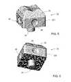
- FIG. 5is a top perspective view of the rotating insert of an embodiment of the training apparatus
- FIG. 6is a bottom perspective view of the rotating insert of FIG. 5 ;
- FIG. 7is a top perspective view of the medium insert of an embodiment of the training apparatus.
- FIG. 8is a bottom perspective view of the medium insert of FIG. 7 ;
- FIG. 9is a top perspective view of the small insert of an embodiment of the training apparatus.
- FIG. 10is a bottom perspective view of the small insert of FIG. 9 ;
- FIG. 11is a perspective view of the platform of the embodiment of FIG. 1 with the medium insert of FIG. 7 and the large insert of FIG. 3 in place;
- FIG. 12is an exploded view of the embodiment of FIG. 11 .
- FIG. 1 and FIG. 2there is shown a one piece platform 13 with a pad 14 attached to the top.
- a keyhole 15 in the platform 13where a variety of inserts as shown in FIG. 3 through FIG. 10 can be arranged.
- the top of the platform 13is sufficiently wide and long to stand on, such as about five inches wide and ten inches long.
- the bottom of the platform 13is sufficiently wide and long to provide stability for the platform 13 when standing on, such as about eight inches wide and fourteen inches long.
- the height of the platform 13is sufficiently tall to provide a step up off the ground, such as about nine inches high.
- the pad 14is sufficiently wide and long to stand on, such as about three to four inches wide and three to four inches long and is about one inch tall.
- the keyhole 15is about one inch deep, six to ten inches long, and of a shape that allows a variety of inserts, such as those of FIG. 3 through FIG. 10 , to fit precisely.
- the platform 13may be made of high-strength plastic or any other sufficiently rigid and strong material, such as wood, metal and the like.
- the pad 14may be made of a rubber like material to yield slightly to the weight of a person standing upon it.
- the platform, inserts, and pads described throughout this disclosuremay be made using any suitable techniques for shaping of these materials into the shapes described herein.
- the apparatus and its partsmay be manufactured by molding techniques known in the art, such as silicon molding or injection molding.
- a large insert 18having a lower portion 20 with an upper portion, or pad, 21 attached to the top.
- Pad 21is similar to pad 14 of FIGS. 1 and 2 .
- posts 19 at the bottomthat fit into a number of positions in the keyhole 15 in FIG. 1 and FIG. 2 .
- dimples 22 on each of the four sidesto use as finger grips to remove the large insert 18 from the platform 13 in FIG. 1 and FIG. 2 .
- the large insert 18is about three to four inches wide and three to four inches long and about two to three inches tall, which includes the posts 19 that are about one inch tall.
- the pad 21is of a size and shape to precisely fit onto the lower portion 20 of the large insert 18 and is about one inch tall.
- pad 21includes four bumps, or protuberances, 211 in its upper surface. Between bumps 211 is a comparatively lower region 212 .
- the unevenness of the upper surface of pad 21may to some degree simulate for a user of the apparatus the feel of balancing on the palm of a human hand.
- the lower portion 20 and the pad 21when inserted in the keyhole 15 of FIG. 1 and FIG. 2 , are sufficiently tall enough to be level with the pad 14 in FIG. 1 and FIG. 2 and provide a level surface on which to stand.
- the large insert 18may be made of high-strength plastic or any other sufficiently rigid and strong material such as wood, metal and the like.
- the pad 21may be made of a rubber like material to yield slightly to the weight of a person standing upon it.
- FIG. 5 and FIG. 6there is shown a rotating insert 23 having a lower portion 231 with a pad 25 attached to the top.
- pad 25is similar to pad 21 of FIGS. 3 and 4 .
- the lower portion 231 of rotating insert 23is about three to four inches wide and three to four inches long and about two to three inches tall, which includes the round post 24 that is about one inch tall.
- the pad 25is of a size and shape to precisely fit onto the lower portion 231 of the rotating insert 23 and is about one inch tall. Together, the lower portion 231 and the pad 25 , when inserted in the keyhole 15 of FIG. 1 and FIG. 2 , are sufficiently tall enough to be level with the pad 14 in FIG. 1 and FIG. 2 and provide a level surface on which to stand.
- the rotating insert 23may be made of high-strength plastic or any other sufficiently rigid and strong material such as wood, metal and the like.
- the pad 25may be made of a rubber like material to yield slightly to the weight of a person standing upon it.
- FIG. 7 and FIG. 8there is shown a medium insert 27 having a lower portion 271 with a pad 29 attached to the top.
- pad 29is similar to pad 21 of FIGS. 3-4 or pad 25 of FIGS. 5-6 , but includes two bumps or protuberances 291 rather than four, with a comparatively lower region 292 between bumps 291 .
- dimples 30 on each of the four sidesto use as finger grips to remove the medium insert 27 from the platform 13 in FIG. 1 and FIG. 2 .
- the lower portion 271 of medium insert 27is about three to four inches wide and one to two inches long and about two to three inches tall, which includes the post 28 that is about 1 inch tall.
- the pad 29is of a size and shape to precisely fit onto the lower portion 271 of medium insert 18 and is about 1 inch tall. Together, the lower portion 271 and the pad 29 , when inserted in the keyhole 15 of FIG. 1 and FIG. 2 , are sufficiently tall enough to be level with the pad 14 in FIG. 1 and FIG. 2 and provide a level surface on which to stand.
- the medium insert 27may be made of high-strength plastic or any other sufficiently rigid and strong material such as wood, metal and the like.
- the pad 29may be made of a rubber like material to yield slightly to the weight of a person standing upon it.
- FIG. 9 and FIG. 10there is shown a small insert 31 having a lower portion 311 with a pad 33 attached to the top.
- pad 33is similar to pad 29 of FIGS. 7 and 8 .
- the lower portion 311 of the small insert 31is about three to four inches wide and one to two inches long and about two inches tall, which includes the post 32 that is about one inch tall.
- the pad 33is of a size and shape to precisely fit onto the small insert 31 and is about one inch tall. Together, the lower portion 311 and the pad 33 , when inserted in the keyhole 15 of FIG. 1 and FIG. 2 , are shorter than the pad 14 in FIG. 1 and FIG. 2 and provide an unlevel surface on which to stand.
- the small insert 31may be made of high-strength plastic or any other sufficiently rigid and strong material such as wood, metal and the like.
- the pad 33may be made of a rubber like material to yield slightly to the weight of a person standing upon it.
- FIG. 11 and FIG. 12there is shown the platform 13 of FIG. 1 and FIG. 2 with the large insert 18 of FIG. 3 and FIG. 4 and the medium insert 27 of FIG. 7 and FIG. 8 in one possible configuration.
- inserts or pedestalssuch as inserts 18 , 23 , 27 , and 31 shown in the figures could be formed as a single piece rather than with separate upper and lower portions.
- Some variationscall for platform 13 being different shapes and styles including different permanent high and low points, a surface with only keyholes 15 for inserts 18 , 23 , 27 , 31 and non-flat bottom surfaces to allow instability.
- Other variationscall for platform 13 to be formed from two or more parts to vary height and ease portability.
- Other variationsinclude the entire device moving, shaking or raising and lowering by mechanical and electrical means.
- Other variationsinclude larger and smaller versions, with varying densities of materials and shapes for the pads 14 , 21 , 25 , 29 , 33 .
- Still other variationsinclude additional inserts of varying size and shape for different balancing objectives.
- Other variationsinclude different adjustment methods, sliding or rotating inserts and shapes of the keyholes 15 .
- Other variationscall for LED or other forms of lights, pressure point sensors, digital displays, audio speakers, microphones with voice recognition, data entry points, pliable and or traction material on the bottom surface and straps or connections to attach the device to ones feet.
Landscapes
- Health & Medical Sciences (AREA)
- General Health & Medical Sciences (AREA)
- Physical Education & Sports Medicine (AREA)
- Life Sciences & Earth Sciences (AREA)
- Biophysics (AREA)
- Orthopedic Medicine & Surgery (AREA)
- Cardiology (AREA)
- Vascular Medicine (AREA)
- Rehabilitation Tools (AREA)
Abstract
Description
Claims (21)
Priority Applications (1)
| Application Number | Priority Date | Filing Date | Title |
|---|---|---|---|
| US13/459,197US9022910B1 (en) | 2011-04-29 | 2012-04-29 | Balance training device and method |
Applications Claiming Priority (2)
| Application Number | Priority Date | Filing Date | Title |
|---|---|---|---|
| US201161517995P | 2011-04-29 | 2011-04-29 | |
| US13/459,197US9022910B1 (en) | 2011-04-29 | 2012-04-29 | Balance training device and method |
Publications (1)
| Publication Number | Publication Date |
|---|---|
| US9022910B1true US9022910B1 (en) | 2015-05-05 |
Family
ID=53001628
Family Applications (1)
| Application Number | Title | Priority Date | Filing Date |
|---|---|---|---|
| US13/459,197Active - Reinstated2032-05-01US9022910B1 (en) | 2011-04-29 | 2012-04-29 | Balance training device and method |
Country Status (1)
| Country | Link |
|---|---|
| US (1) | US9022910B1 (en) |
Cited By (2)
| Publication number | Priority date | Publication date | Assignee | Title |
|---|---|---|---|---|
| US11471738B2 (en)* | 2019-11-01 | 2022-10-18 | Hilton Bennett | Indoor-traditional crack climbing hold |
| USD1047034S1 (en)* | 2022-05-25 | 2024-10-15 | Charles Perriere | Equipment for acrobatic sports |
Citations (46)
| Publication number | Priority date | Publication date | Assignee | Title |
|---|---|---|---|---|
| US1481038A (en)* | 1919-05-23 | 1924-01-15 | Milton E Stephenson | Foot-massaging device |
| US3005282A (en)* | 1958-01-28 | 1961-10-24 | Interlego Ag | Toy building brick |
| US3116570A (en)* | 1959-11-05 | 1964-01-07 | Torricelli Decio | Brick |
| US3612465A (en)* | 1969-08-01 | 1971-10-12 | Lloyd O Barrett | Supporting apparatus for use in a gravity-free environment |
| US4274824A (en)* | 1978-10-02 | 1981-06-23 | Mullins Wayne L | Mold box apparatus |
| US4390178A (en)* | 1980-06-20 | 1983-06-28 | Elliot Rudell | Pivotal jumping stick |
| US4461472A (en)* | 1982-12-27 | 1984-07-24 | Rosendo Martinez | Exercise device beneficial to the metatarsal arch |
| US4606732A (en)* | 1984-06-15 | 1986-08-19 | Ronald Lyman | Interlocking toy building blocks with interconnecting, releasable hinges |
| EP0300243A1 (en)* | 1987-07-22 | 1989-01-25 | Schütt & Grundei Orthopädietechnik GmbH | Medical pad for patients |
| US5197975A (en)* | 1989-01-09 | 1993-03-30 | Bruno Mombrinie | Radiolucent spine support frame |
| US5226868A (en)* | 1992-05-27 | 1993-07-13 | Montgomery Calvin W | Power push-up device |
| US5230195A (en)* | 1991-06-21 | 1993-07-27 | Sease Stanley R | Insulating molded plastic building unit |
| US5263863A (en)* | 1992-10-27 | 1993-11-23 | Stefani Nicholas J | Weight shift trainer for golfers |
| US5453065A (en)* | 1994-08-15 | 1995-09-26 | Kingi Cycle Co., Ltd. | Exerciser with combined stepping and twisting functions |
| US5474509A (en)* | 1993-07-29 | 1995-12-12 | Athletic Clubs Of America | Adjustable exercise platform |
| US5647185A (en)* | 1993-11-19 | 1997-07-15 | Forlini; Emidio J. | Structural blocks and assemblies thereof |
| US5651753A (en)* | 1993-06-28 | 1997-07-29 | Wilkinson; William T. | Multi-level aerobic step device |
| US5772559A (en)* | 1996-05-21 | 1998-06-30 | Sithole; Deborah | Modular aerobic-exercise stepper |
| US5819743A (en)* | 1997-08-22 | 1998-10-13 | Mcmillin; James A. | Extremity pillow |
| US5839991A (en)* | 1996-11-12 | 1998-11-24 | Hall; Timothy L. | Portable occupational therapy device |
| US5934037A (en)* | 1997-12-22 | 1999-08-10 | Bundra; Octavian | Building block |
| US5954340A (en)* | 1998-08-13 | 1999-09-21 | Mattel, Inc. | Multiple tier token balance game |
| US6182314B1 (en)* | 1995-06-07 | 2001-02-06 | Larry G. Frydman | Orthopedic support pillow |
| USD441823S1 (en) | 1999-04-13 | 2001-05-08 | Ccg Cheer Products, Inc. | Practice platform |
| US20010016544A1 (en)* | 1998-10-20 | 2001-08-23 | Mckechnie Alexander | Torsion board |
| US6648715B2 (en)* | 2001-10-25 | 2003-11-18 | Benjamin I. Wiens | Snap-fit construction system |
| US20050165450A1 (en)* | 2003-12-30 | 2005-07-28 | Yngrid Perez-Torrens | Passive back extensor device to treat trigger point - back pain |
| US6945919B2 (en)* | 2003-07-11 | 2005-09-20 | Lien Chuan Yang | Balance-exercising semi-spherical apparatus |
| US20050245363A1 (en) | 2004-04-29 | 2005-11-03 | Shumrick Patrick L | Device for promoting reflective neuromuscular training |
| US20060014615A1 (en)* | 2004-07-15 | 2006-01-19 | Godbold Temico R | Pushup exercise device |
| US20060035771A1 (en)* | 2004-08-06 | 2006-02-16 | Ultimate Push-Up | Push-up exercise apparatus |
| US20060040809A1 (en)* | 2004-07-15 | 2006-02-23 | Godbold Temico R | Pushup exercise device |
| US7008359B2 (en)* | 2002-10-18 | 2006-03-07 | Reebok International Ltd. | Exercise apparatus |
| US7063646B1 (en)* | 1999-06-24 | 2006-06-20 | Ali Slimi | Apparatus for performing rotating figures or body exercises, and associated grip member |
| US20060255545A1 (en)* | 2003-07-03 | 2006-11-16 | Baldassare Giglia | Game device, particularly for searching the static balance of a body |
| US7169099B1 (en) | 2003-09-22 | 2007-01-30 | Nike International Ltd. | Balancing object |
| US7357766B2 (en)* | 2005-09-06 | 2008-04-15 | Functionalinnovations, Llc | Adaptable body conditioning apparatus |
| US20090193740A1 (en)* | 2005-01-04 | 2009-08-06 | Kerry Robert Bennett | Composite masonry building block |
| US7694975B1 (en)* | 2008-05-20 | 2010-04-13 | Ronald Alton Darby | Toys or games using a launching device and foam blocks |
| US7708615B2 (en)* | 2004-10-20 | 2010-05-04 | Lego A/S | Toy building system with function bricks |
| US7824319B2 (en)* | 2008-03-28 | 2010-11-02 | Carlesimo Michael O | Push-up system |
| US8105219B1 (en) | 2009-04-06 | 2012-01-31 | Sloan Paula E | Cheerleader training device |
| US8157713B1 (en)* | 2010-09-14 | 2012-04-17 | Steve Siskowic | Attachable exercise device and method of use thereof |
| US8176697B1 (en)* | 2009-09-01 | 2012-05-15 | Bolander Ii Larry J | Building block |
| US20120131752A1 (en)* | 2009-07-29 | 2012-05-31 | Technogel Italia S.R.L. | Modular support element |
| US20130217545A1 (en)* | 2012-02-17 | 2013-08-22 | Amber Orenstein | Aerobic step |
- 2012
- 2012-04-29USUS13/459,197patent/US9022910B1/enactiveActive - Reinstated
Patent Citations (48)
| Publication number | Priority date | Publication date | Assignee | Title |
|---|---|---|---|---|
| US1481038A (en)* | 1919-05-23 | 1924-01-15 | Milton E Stephenson | Foot-massaging device |
| US3005282A (en)* | 1958-01-28 | 1961-10-24 | Interlego Ag | Toy building brick |
| US3116570A (en)* | 1959-11-05 | 1964-01-07 | Torricelli Decio | Brick |
| US3612465A (en)* | 1969-08-01 | 1971-10-12 | Lloyd O Barrett | Supporting apparatus for use in a gravity-free environment |
| US4274824A (en)* | 1978-10-02 | 1981-06-23 | Mullins Wayne L | Mold box apparatus |
| US4390178A (en)* | 1980-06-20 | 1983-06-28 | Elliot Rudell | Pivotal jumping stick |
| US4461472A (en)* | 1982-12-27 | 1984-07-24 | Rosendo Martinez | Exercise device beneficial to the metatarsal arch |
| US4606732A (en)* | 1984-06-15 | 1986-08-19 | Ronald Lyman | Interlocking toy building blocks with interconnecting, releasable hinges |
| EP0300243A1 (en)* | 1987-07-22 | 1989-01-25 | Schütt & Grundei Orthopädietechnik GmbH | Medical pad for patients |
| US5197975A (en)* | 1989-01-09 | 1993-03-30 | Bruno Mombrinie | Radiolucent spine support frame |
| US5230195A (en)* | 1991-06-21 | 1993-07-27 | Sease Stanley R | Insulating molded plastic building unit |
| US5226868A (en)* | 1992-05-27 | 1993-07-13 | Montgomery Calvin W | Power push-up device |
| US5263863A (en)* | 1992-10-27 | 1993-11-23 | Stefani Nicholas J | Weight shift trainer for golfers |
| US5651753A (en)* | 1993-06-28 | 1997-07-29 | Wilkinson; William T. | Multi-level aerobic step device |
| US5474509A (en)* | 1993-07-29 | 1995-12-12 | Athletic Clubs Of America | Adjustable exercise platform |
| US5647185A (en)* | 1993-11-19 | 1997-07-15 | Forlini; Emidio J. | Structural blocks and assemblies thereof |
| US5453065A (en)* | 1994-08-15 | 1995-09-26 | Kingi Cycle Co., Ltd. | Exerciser with combined stepping and twisting functions |
| US6182314B1 (en)* | 1995-06-07 | 2001-02-06 | Larry G. Frydman | Orthopedic support pillow |
| US5772559A (en)* | 1996-05-21 | 1998-06-30 | Sithole; Deborah | Modular aerobic-exercise stepper |
| US5839991A (en)* | 1996-11-12 | 1998-11-24 | Hall; Timothy L. | Portable occupational therapy device |
| US5819743A (en)* | 1997-08-22 | 1998-10-13 | Mcmillin; James A. | Extremity pillow |
| US5934037A (en)* | 1997-12-22 | 1999-08-10 | Bundra; Octavian | Building block |
| US5954340A (en)* | 1998-08-13 | 1999-09-21 | Mattel, Inc. | Multiple tier token balance game |
| US20010016544A1 (en)* | 1998-10-20 | 2001-08-23 | Mckechnie Alexander | Torsion board |
| USD441823S1 (en) | 1999-04-13 | 2001-05-08 | Ccg Cheer Products, Inc. | Practice platform |
| US7063646B1 (en)* | 1999-06-24 | 2006-06-20 | Ali Slimi | Apparatus for performing rotating figures or body exercises, and associated grip member |
| US6648715B2 (en)* | 2001-10-25 | 2003-11-18 | Benjamin I. Wiens | Snap-fit construction system |
| US7008359B2 (en)* | 2002-10-18 | 2006-03-07 | Reebok International Ltd. | Exercise apparatus |
| US20060255545A1 (en)* | 2003-07-03 | 2006-11-16 | Baldassare Giglia | Game device, particularly for searching the static balance of a body |
| US6945919B2 (en)* | 2003-07-11 | 2005-09-20 | Lien Chuan Yang | Balance-exercising semi-spherical apparatus |
| US7169099B1 (en) | 2003-09-22 | 2007-01-30 | Nike International Ltd. | Balancing object |
| US20050165450A1 (en)* | 2003-12-30 | 2005-07-28 | Yngrid Perez-Torrens | Passive back extensor device to treat trigger point - back pain |
| US20050245363A1 (en) | 2004-04-29 | 2005-11-03 | Shumrick Patrick L | Device for promoting reflective neuromuscular training |
| US20060040809A1 (en)* | 2004-07-15 | 2006-02-23 | Godbold Temico R | Pushup exercise device |
| US20060014615A1 (en)* | 2004-07-15 | 2006-01-19 | Godbold Temico R | Pushup exercise device |
| US20060035771A1 (en)* | 2004-08-06 | 2006-02-16 | Ultimate Push-Up | Push-up exercise apparatus |
| US7708615B2 (en)* | 2004-10-20 | 2010-05-04 | Lego A/S | Toy building system with function bricks |
| US20090193740A1 (en)* | 2005-01-04 | 2009-08-06 | Kerry Robert Bennett | Composite masonry building block |
| US7357766B2 (en)* | 2005-09-06 | 2008-04-15 | Functionalinnovations, Llc | Adaptable body conditioning apparatus |
| US7753831B2 (en)* | 2005-09-06 | 2010-07-13 | Functional Innovations, Llc | Adaptable body conditioning apparatus |
| US7824319B2 (en)* | 2008-03-28 | 2010-11-02 | Carlesimo Michael O | Push-up system |
| US7694975B1 (en)* | 2008-05-20 | 2010-04-13 | Ronald Alton Darby | Toys or games using a launching device and foam blocks |
| US8105219B1 (en) | 2009-04-06 | 2012-01-31 | Sloan Paula E | Cheerleader training device |
| US8343022B1 (en) | 2009-04-06 | 2013-01-01 | Cheerful Athletics, Llc | Cheerleader training device |
| US20120131752A1 (en)* | 2009-07-29 | 2012-05-31 | Technogel Italia S.R.L. | Modular support element |
| US8176697B1 (en)* | 2009-09-01 | 2012-05-15 | Bolander Ii Larry J | Building block |
| US8157713B1 (en)* | 2010-09-14 | 2012-04-17 | Steve Siskowic | Attachable exercise device and method of use thereof |
| US20130217545A1 (en)* | 2012-02-17 | 2013-08-22 | Amber Orenstein | Aerobic step |
Non-Patent Citations (3)
| Title |
|---|
| Icepice. "lego sofa." Apr. 12, 2010. .* |
| Icepice. "lego sofa." Apr. 12, 2010. <icepice.blogspot.com/2010/04/12-most-creative-unusual-sofa-designs.html>.* |
| More Images from Cheersport in Atlanta!, website blog post, Feb. 11, 2010, pp. 3-4, http://www.confidentcheerleadingblog.com/tag/nfinity/, online. |
Cited By (2)
| Publication number | Priority date | Publication date | Assignee | Title |
|---|---|---|---|---|
| US11471738B2 (en)* | 2019-11-01 | 2022-10-18 | Hilton Bennett | Indoor-traditional crack climbing hold |
| USD1047034S1 (en)* | 2022-05-25 | 2024-10-15 | Charles Perriere | Equipment for acrobatic sports |
Similar Documents
| Publication | Publication Date | Title |
|---|---|---|
| US20120258841A1 (en) | Exercise and balance device | |
| US9056222B2 (en) | Total body exercise device | |
| US8267845B2 (en) | Physical fitness and rehabilitation apparatus | |
| US7833144B1 (en) | Strength training workout bench | |
| US9387363B1 (en) | Ball and board balance training device | |
| US8357077B2 (en) | Physical fitness and rehabilitation apparatus | |
| US7993253B2 (en) | Agility device | |
| US8444532B1 (en) | Fitness platform having a plurality of interchangeable surfaces | |
| US7618358B2 (en) | Training device | |
| US8343022B1 (en) | Cheerleader training device | |
| US9498664B2 (en) | Foot, leg and arm support for exercise | |
| US20140329651A1 (en) | Total Body Exercise Device | |
| US8998784B1 (en) | Cheerleader training device | |
| US9138613B2 (en) | Weightlifting aid | |
| US9750975B2 (en) | Push-up exercise device | |
| US11198030B2 (en) | Ped-A-Pull exercise apparatus | |
| CN206304324U (en) | A kind of callisthenics physical strength training device | |
| US9022910B1 (en) | Balance training device and method | |
| US20090170673A1 (en) | Methods and devices for exercising | |
| US20170095696A1 (en) | Balance and Spin Practice Board | |
| KR101464291B1 (en) | Healthcare Exercise Device For Entertainment | |
| NZ592522A (en) | Vertical treadmill exercise apparatus with a variable angle running surface and an user seat and support | |
| US10176790B2 (en) | Guitar support | |
| CN101637644B (en) | Exercise apparatus | |
| KR102843629B1 (en) | Exclusive device for stretching and balance exercises |
Legal Events
| Date | Code | Title | Description |
|---|---|---|---|
| ZAAA | Notice of allowance and fees due | Free format text:ORIGINAL CODE: NOA | |
| ZAAB | Notice of allowance mailed | Free format text:ORIGINAL CODE: MN/=. | |
| STCF | Information on status: patent grant | Free format text:PATENTED CASE | |
| AS | Assignment | Owner name:YEHL VENTURES LLC, TEXAS Free format text:CHANGE OF NAME;ASSIGNOR:YEHL & JORDAN LLC;REEL/FRAME:046339/0330 Effective date:20180317 | |
| FEPP | Fee payment procedure | Free format text:MAINTENANCE FEE REMINDER MAILED (ORIGINAL EVENT CODE: REM.); ENTITY STATUS OF PATENT OWNER: SMALL ENTITY | |
| FEPP | Fee payment procedure | Free format text:SURCHARGE FOR LATE PAYMENT, SMALL ENTITY (ORIGINAL EVENT CODE: M2554); ENTITY STATUS OF PATENT OWNER: SMALL ENTITY | |
| MAFP | Maintenance fee payment | Free format text:PAYMENT OF MAINTENANCE FEE, 4TH YR, SMALL ENTITY (ORIGINAL EVENT CODE: M2551); ENTITY STATUS OF PATENT OWNER: SMALL ENTITY Year of fee payment:4 | |
| FEPP | Fee payment procedure | Free format text:MAINTENANCE FEE REMINDER MAILED (ORIGINAL EVENT CODE: REM.); ENTITY STATUS OF PATENT OWNER: SMALL ENTITY | |
| LAPS | Lapse for failure to pay maintenance fees | Free format text:PATENT EXPIRED FOR FAILURE TO PAY MAINTENANCE FEES (ORIGINAL EVENT CODE: EXP.); ENTITY STATUS OF PATENT OWNER: SMALL ENTITY | |
| STCH | Information on status: patent discontinuation | Free format text:PATENT EXPIRED DUE TO NONPAYMENT OF MAINTENANCE FEES UNDER 37 CFR 1.362 | |
| FP | Lapsed due to failure to pay maintenance fee | Effective date:20230505 | |
| PRDP | Patent reinstated due to the acceptance of a late maintenance fee | Effective date:20240816 | |
| FEPP | Fee payment procedure | Free format text:PETITION RELATED TO MAINTENANCE FEES FILED (ORIGINAL EVENT CODE: PMFP); ENTITY STATUS OF PATENT OWNER: SMALL ENTITY Free format text:PETITION RELATED TO MAINTENANCE FEES GRANTED (ORIGINAL EVENT CODE: PMFG); ENTITY STATUS OF PATENT OWNER: SMALL ENTITY Free format text:SURCHARGE, PETITION TO ACCEPT PYMT AFTER EXP, UNINTENTIONAL. (ORIGINAL EVENT CODE: M2558); ENTITY STATUS OF PATENT OWNER: SMALL ENTITY | |
| MAFP | Maintenance fee payment | Free format text:PAYMENT OF MAINTENANCE FEE, 8TH YR, SMALL ENTITY (ORIGINAL EVENT CODE: M2552); ENTITY STATUS OF PATENT OWNER: SMALL ENTITY Year of fee payment:8 | |
| STCF | Information on status: patent grant | Free format text:PATENTED CASE |