US9022404B2 - Method and device for adjusting the supporting load of a central axle trailer - Google Patents
Method and device for adjusting the supporting load of a central axle trailerDownload PDFInfo
- Publication number
- US9022404B2 US9022404B2US13/652,953US201213652953AUS9022404B2US 9022404 B2US9022404 B2US 9022404B2US 201213652953 AUS201213652953 AUS 201213652953AUS 9022404 B2US9022404 B2US 9022404B2
- Authority
- US
- United States
- Prior art keywords
- supporting load
- axle
- pneumatic suspension
- trailer
- axles
- Prior art date
- Legal status (The legal status is an assumption and is not a legal conclusion. Google has not performed a legal analysis and makes no representation as to the accuracy of the status listed.)
- Active, expires
Links
- 238000000034methodMethods0.000titleclaimsabstractdescription18
- 239000000725suspensionSubstances0.000claimsabstractdescription110
- 230000008878couplingEffects0.000claimsdescription21
- 238000010168coupling processMethods0.000claimsdescription21
- 238000005859coupling reactionMethods0.000claimsdescription21
- 230000003213activating effectEffects0.000claimsdescription3
- 230000004075alterationEffects0.000abstractdescription17
- 238000010586diagramMethods0.000description13
- 230000006870functionEffects0.000description9
- 230000008901benefitEffects0.000description4
- 238000010276constructionMethods0.000description4
- 238000001514detection methodMethods0.000description4
- 230000005484gravityEffects0.000description2
- 230000001133accelerationEffects0.000description1
- 230000006978adaptationEffects0.000description1
- 230000000694effectsEffects0.000description1
- 238000005259measurementMethods0.000description1
- 238000013022ventingMethods0.000description1
Images


Classifications
- B—PERFORMING OPERATIONS; TRANSPORTING
- B60—VEHICLES IN GENERAL
- B60G—VEHICLE SUSPENSION ARRANGEMENTS
- B60G17/00—Resilient suspensions having means for adjusting the spring or vibration-damper characteristics, for regulating the distance between a supporting surface and a sprung part of vehicle or for locking suspension during use to meet varying vehicular or surface conditions, e.g. due to speed or load
- B60G17/02—Spring characteristics, e.g. mechanical springs and mechanical adjusting means
- B60G17/04—Spring characteristics, e.g. mechanical springs and mechanical adjusting means fluid spring characteristics
- B60G17/052—Pneumatic spring characteristics
- B—PERFORMING OPERATIONS; TRANSPORTING
- B60—VEHICLES IN GENERAL
- B60G—VEHICLE SUSPENSION ARRANGEMENTS
- B60G17/00—Resilient suspensions having means for adjusting the spring or vibration-damper characteristics, for regulating the distance between a supporting surface and a sprung part of vehicle or for locking suspension during use to meet varying vehicular or surface conditions, e.g. due to speed or load
- B60G17/015—Resilient suspensions having means for adjusting the spring or vibration-damper characteristics, for regulating the distance between a supporting surface and a sprung part of vehicle or for locking suspension during use to meet varying vehicular or surface conditions, e.g. due to speed or load the regulating means comprising electric or electronic elements
- B60G17/0152—Resilient suspensions having means for adjusting the spring or vibration-damper characteristics, for regulating the distance between a supporting surface and a sprung part of vehicle or for locking suspension during use to meet varying vehicular or surface conditions, e.g. due to speed or load the regulating means comprising electric or electronic elements characterised by the action on a particular type of suspension unit
- B60G17/0155—Resilient suspensions having means for adjusting the spring or vibration-damper characteristics, for regulating the distance between a supporting surface and a sprung part of vehicle or for locking suspension during use to meet varying vehicular or surface conditions, e.g. due to speed or load the regulating means comprising electric or electronic elements characterised by the action on a particular type of suspension unit pneumatic unit
- B—PERFORMING OPERATIONS; TRANSPORTING
- B60—VEHICLES IN GENERAL
- B60G—VEHICLE SUSPENSION ARRANGEMENTS
- B60G17/00—Resilient suspensions having means for adjusting the spring or vibration-damper characteristics, for regulating the distance between a supporting surface and a sprung part of vehicle or for locking suspension during use to meet varying vehicular or surface conditions, e.g. due to speed or load
- B60G17/015—Resilient suspensions having means for adjusting the spring or vibration-damper characteristics, for regulating the distance between a supporting surface and a sprung part of vehicle or for locking suspension during use to meet varying vehicular or surface conditions, e.g. due to speed or load the regulating means comprising electric or electronic elements
- B60G17/018—Resilient suspensions having means for adjusting the spring or vibration-damper characteristics, for regulating the distance between a supporting surface and a sprung part of vehicle or for locking suspension during use to meet varying vehicular or surface conditions, e.g. due to speed or load the regulating means comprising electric or electronic elements characterised by the use of a specific signal treatment or control method
- B—PERFORMING OPERATIONS; TRANSPORTING
- B60—VEHICLES IN GENERAL
- B60G—VEHICLE SUSPENSION ARRANGEMENTS
- B60G5/00—Resilient suspensions for a set of tandem wheels or axles having interrelated movements
- B60G5/04—Resilient suspensions for a set of tandem wheels or axles having interrelated movements with two or more pivoted arms, the movements of which are resiliently interrelated, e.g. the arms being rigid
- B—PERFORMING OPERATIONS; TRANSPORTING
- B60—VEHICLES IN GENERAL
- B60G—VEHICLE SUSPENSION ARRANGEMENTS
- B60G2202/00—Indexing codes relating to the type of spring, damper or actuator
- B60G2202/10—Type of spring
- B60G2202/15—Fluid spring
- B60G2202/152—Pneumatic spring
- B—PERFORMING OPERATIONS; TRANSPORTING
- B60—VEHICLES IN GENERAL
- B60G—VEHICLE SUSPENSION ARRANGEMENTS
- B60G2300/00—Indexing codes relating to the type of vehicle
- B60G2300/02—Trucks; Load vehicles
- B60G2300/026—Heavy duty trucks
- B60G2300/0262—Multi-axle trucks
- B—PERFORMING OPERATIONS; TRANSPORTING
- B60—VEHICLES IN GENERAL
- B60G—VEHICLE SUSPENSION ARRANGEMENTS
- B60G2300/00—Indexing codes relating to the type of vehicle
- B60G2300/04—Trailers
- B60G2300/042—Semi-trailers
- B—PERFORMING OPERATIONS; TRANSPORTING
- B60—VEHICLES IN GENERAL
- B60G—VEHICLE SUSPENSION ARRANGEMENTS
- B60G2400/00—Indexing codes relating to detected, measured or calculated conditions or factors
- B60G2400/50—Pressure
- B60G2400/51—Pressure in suspension unit
- B60G2400/512—Pressure in suspension unit in spring
- B60G2400/5122—Fluid spring
- B60G2400/51222—Pneumatic
- B—PERFORMING OPERATIONS; TRANSPORTING
- B60—VEHICLES IN GENERAL
- B60G—VEHICLE SUSPENSION ARRANGEMENTS
- B60G2400/00—Indexing codes relating to detected, measured or calculated conditions or factors
- B60G2400/60—Load
- B60G2400/61—Load distribution
- B—PERFORMING OPERATIONS; TRANSPORTING
- B60—VEHICLES IN GENERAL
- B60G—VEHICLE SUSPENSION ARRANGEMENTS
- B60G2400/00—Indexing codes relating to detected, measured or calculated conditions or factors
- B60G2400/90—Other conditions or factors
- B60G2400/97—Relation between towing and towed vehicle, e.g. tractor-trailer combination
- B—PERFORMING OPERATIONS; TRANSPORTING
- B60—VEHICLES IN GENERAL
- B60G—VEHICLE SUSPENSION ARRANGEMENTS
- B60G2500/00—Indexing codes relating to the regulated action or device
- B60G2500/20—Spring action or springs
- B—PERFORMING OPERATIONS; TRANSPORTING
- B60—VEHICLES IN GENERAL
- B60G—VEHICLE SUSPENSION ARRANGEMENTS
- B60G2500/00—Indexing codes relating to the regulated action or device
- B60G2500/20—Spring action or springs
- B60G2500/201—Air spring system type
- B60G2500/2014—Closed systems
- B—PERFORMING OPERATIONS; TRANSPORTING
- B60—VEHICLES IN GENERAL
- B60G—VEHICLE SUSPENSION ARRANGEMENTS
- B60G2500/00—Indexing codes relating to the regulated action or device
- B60G2500/20—Spring action or springs
- B60G2500/22—Spring constant
- B—PERFORMING OPERATIONS; TRANSPORTING
- B60—VEHICLES IN GENERAL
- B60G—VEHICLE SUSPENSION ARRANGEMENTS
- B60G2800/00—Indexing codes relating to the type of movement or to the condition of the vehicle and to the end result to be achieved by the control action
- B60G2800/90—System Controller type
- B60G2800/91—Suspension Control
- B60G2800/915—Suspension load distribution
Definitions
- the present inventiongenerally relates to embodiments of a method and electronic control device for adjusting the supporting load of a central axle trailer.
- Trailer vehiclescan be central axle trailers in which the vehicle axles are arranged centrally relative to the longitudinal direction of the trailer vehicle, i.e., approximately centrally relative to the longitudinal extent of the loading surface.
- Central axle trailersexist in embodiments with a single central vehicle axle or a plurality of vehicle axles, for example two or three axles, which are arranged relatively closely to one another and centrally relative to the longitudinal extent of the loading surface.
- a central axle traileris not configured for coupling to a semitrailer truck, but comprises a trailer coupling via which it may be coupled to a coupling device of a truck configured as a counter-piece.
- a supporting load that is too smallmay result in unstable driving behavior of the tractor vehicle or the entire tractor/trailer combination.
- a supporting load that is too greatmay lead to overloading of the tractor vehicle, in particular the rear chassis structure.
- the legal supporting load range in some jurisdictionscan be 0.5 to 2 tons.
- a method for adjusting the supporting load of a central axle trailer equipped with at least two axles with pneumatic suspensions and a pneumatic suspension systemwhich comprises separate pneumatic suspension circuits on the at least two axles with pneumatic suspensions, includes adjusting the respective quantities of air separately from one another based on a determination as to whether the current supporting load is outside a permitted supporting load range.
- the current supporting loadexceeds the permitted supporting load range, the current supporting load is reduced by separate alteration of the quantity of air in at least one of the pneumatic suspension circuits on the axle; and when the current supporting load is below the permitted supporting load range, the current supporting load is increased by separate alteration of the quantity of air in at least one of the pneumatic suspension circuits on the axle.
- the pneumatic suspension system for at least two axlespermits the separate adjustment on the axles of the respective quantities of air—making it possible to increase or reduce the pressure of each axle or set of axles relative to the other axle(s). It should be appreciated that this was not possible in conventional central axle trailers. If the central axle trailers were even provided with a pneumatic suspension system, the pneumatic suspension bellows were connected together to form a single pneumatic suspension circuit, so that separate adjustment of the quantities of air on the axle was not possible and/or where a lifting axle or drive axle was used, the pressure of the axle could only be reduced.
- the permitted supporting load rangecan be a range limited by an upper and lower limit value, or a range that is open-ended on one side.
- the permitted supporting load rangemay include, for example, the range of all positive values of the supporting load including the value zero, i.e., values outside the permitted supporting load range are thus negative values.
- positive values of the supporting loadare understood to be values when the trailer coupling is pulled in the direction of the roadway.
- the permitted supporting load rangecan also be a permitted range specified by the manufacturer of the central axle trailer or the tractor vehicle, or a permitted supporting load range set by law, for example the permitted range applicable in the EU of 0.5 to 2 tons.
- the current supporting load on the trailer couplingcan be measured, for example by a force sensor.
- Establishing whether the current supporting load is outside the permitted supporting load range and the optional alteration of the quantity of air in at least one of the pneumatic suspension circuitscan be carried out automatically, for example, by an electronic control device.
- the electronic control devicecan, for example, be an electronically controlled pneumatic suspension system or an electronically controlled braking system of the central axle trailer.
- the electronic control devicecan be connected to an electrically actuatable pneumatic valve device. By activating the valve device by means of the electronic control device, the quantity of air can be correspondingly altered by air being filled into pneumatic suspension bellows from a storage tank, or by air being blown out of the pneumatic suspension bellows.
- the electronic control devicecan be connected to one or more corresponding sensors, for example to a force sensor arranged on the trailer coupling, by which the supporting load may be measured.
- axle loads of the at least two axles with pneumatic suspensionby means of the axle loads of the at least two axles with pneumatic suspension, a determination is made as to whether the current supporting load is outside a permitted supporting load range, and then optionally a corresponding alteration of the quantity of air is carried out in at least one of the pneumatic suspension circuits.
- the axle loadscan be determined by the electronic control device, for example via axle load sensors.
- the axle loadscan also be determined via air pressure sensors connected to the respective pneumatic suspension bellows, by additionally taking into account geometric data of the pneumatic suspension bellows and the axle suspension.
- a separate axle load sensor or an air pressure sensorneed not be provided for each axle to be measured with regard to axle load.
- the brake slip on the axlescan be monitored, for example when the central axle trailer is braked. If there is a differential value between the brake slip values of the axles, the axle load of an axle not provided with sensors can be calculated via this differential value by utilizing an axle load of another axle detected by a sensor (see, e.g., DE 197 07 210 B4 and DE 10 2008 003 206 A1).
- the supporting load presentcan be calculated directly.
- direct calculation of the supporting loadis not a requirement for implementing the present invention.
- An approximate estimation of the supporting loadcan be used.
- the current supporting loadis adapted by separate alteration of the quantity of air in at least one of the pneumatic suspension circuits on the axle until the current supporting load is within the permitted supporting load range.
- the adaptation of the supporting load in this casecan be terminated when the permitted supporting load range is reached or continued, for example, approximately until the middle of the permitted supporting load range is reached.
- Limits determined by disadvantageous loading of the central axle trailer or by limit values for permitted axle loadsmay be set for adapting the current supporting load by separate alteration of the quantity of air in at least one of the pneumatic suspension circuits on the axle. In some cases, it may arise that the current supporting load is not able to be altered until it is within the permitted supporting load range, by altering the quantity of air in at least one of the pneumatic suspension circuits. In this case, the supporting load is altered sufficiently until it comes at least as close as possible to the permitted supporting load range.
- the current supporting loadis adapted by separate alteration of the quantity of air in at least one of the pneumatic suspension circuits on the axle, until on at least one axle the permitted limit load value is reached.
- the alteration of the quantity of air in at least one of the pneumatic suspension circuitsis automatically carried out by an electronic control device by activating at least one electrically actuatable pneumatic valve device.
- the electrically actuatable pneumatic valve devicecan be a common valve device, for example a dual-circuit construction if two separate pneumatic suspension circuits have to be controlled, or a multi-circuit construction in a pneumatic suspension system having a plurality of pneumatic suspension circuits.
- the valve devicecan also have individual valves for each pneumatic suspension circuit, for example in each case a valve with the functions of maintaining the quantity of air, increasing the quantity of air and reducing the quantity of air in the respective pneumatic suspension circuit.
- the axle loadscan be detected by pressure sensors connected to pneumatic suspension bellows of the pneumatic suspension circuits. This has the advantage that the axle loads may be detected in a simple, cost-effective manner with a high degree of accuracy.
- the axle load of a second axle arranged behind the first axle of the central axle traileris reduced relative to the axle load of the first axle.
- the quantity of air in the pneumatic suspension circuit of the second axlecan be reduced or the quantity of air in the pneumatic suspension circuit of the first axle can be increased or both.
- the pneumatic suspension systemhas a level control system, i.e., a function of maintaining a desired, constant level of the structure of the central axle trailer, then the level control function is overridden by the aforementioned function of adapting the current supporting load by separate alteration of the quantity of air in at least one of the pneumatic suspension circuits on the axle.
- the second axleforms the reference variable for adjusting the level and the first axle is simply adjusted therewith.
- the axle lifting device of one or more lifting axlesis automatically actuated if the current supporting load is outside the permitted supporting load range.
- the current supporting loadcan be influenced to an even greater extent in the desired direction, so as to be finally in the permitted supporting load range or at least in the vicinity thereof.
- a lifting axlecan be automatically raised or lowered.
- an additional torque required by the mass of the lifting axleis produced around the axle remaining on the ground and/or the axles remaining on the ground, which may additionally influence the current supporting load in the desired direction.
- a first, front axle of the central axle trailercan be raised by means of the axle lifting device.
- a second, rear axle of the central axle trailercan be raised by means of the axle lifting device.
- the claimed inventionalso is directed to an electronic control device that is configured to adjust the supporting load of the central axle trailer according to one of the method embodiments set forth above. It is further directed to a pneumatic suspension system (which can be equipped with the electronic control device) designed for the central axle trailer having at least two axles with pneumatic suspension, wherein the pneumatic suspension system has separate pneumatic suspension circuits on the axle by which the respective quantities of air can be adjusted separately from one another.
- a pneumatic suspension systemwhich can be equipped with the electronic control device designed for the central axle trailer having at least two axles with pneumatic suspension, wherein the pneumatic suspension system has separate pneumatic suspension circuits on the axle by which the respective quantities of air can be adjusted separately from one another.
- An advantageous embodiment of the inventionrelates to a pneumatic suspension system of the type described above for a central axle trailer comprising more than two axles with pneumatic suspension, wherein the pneumatic suspension system has a smaller number of separate pneumatic suspension circuits on the axle than the number of axles with pneumatic suspension of the central axle trailer.
- the pneumatic suspension bellows of a plurality of axlesare connected to form a common pneumatic suspension circuit. This permits a particularly cost-effective implementation of the pneumatic suspension system as an individual, separate pneumatic suspension circuit is not required for each axle with pneumatic suspension and thus the number of components required for controlling the quantities of air may be kept low.
- the present inventionaccordingly comprises the various steps and the relation of one or more of such steps with respect to each of the others, and embodies features of construction, combinations of elements, and arrangement of parts which are adapted to effect such steps, all as exemplified in the following detailed disclosure, and the scope of the invention will be indicated in the claims.
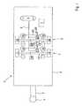
- FIG. 1is a schematic plan view of a dual-axle central axle trailer according to an embodiment of the present invention
- FIG. 2is a side view of the central axle trailer embodiment depicted in FIG. 1 ;
- FIG. 3depicts various force/time diagrams relevant to embodiments of the present invention.
- FIG. 4is a side view of another central axle trailer according to an embodiment of the present invention.
- FIG. 1shows a central axle trailer 8 in schematic plan view.
- the central axle trailer 8comprises a first front axle 1 with pneumatic suspension and a second rear axle 2 with pneumatic suspension.
- An “axle” in this senseencompasses the arrangement consisting of one respective axle rod 13 , 23 and wheels 11 , 12 , 21 , 22 connected thereto.
- the first axle 1is suspended via pneumatic suspension bellows 15 , 16 relative to a trailer structure 3 .
- the second axle 2is suspended via pneumatic suspension bellows 25 , 26 relative to the trailer structure 3 .
- the trailer structure 3 of the central axle trailer 8is provided on the front with a trailer coupling 4 via a coupling rod 5 .
- the central axle trailer 8is coupled to a tractor vehicle via the trailer coupling 4 .
- the pneumatic suspension bellows 15 , 16 of the first axle 1are connected together via pneumatic lines 19 and to a first electrically actuatable pneumatic valve device 17 , as well as a first pressure sensor 18 .
- a first pneumatic suspension circuit 15 , 16 , 17 , 18 , 19is formed.
- the pneumatic suspension bellows 25 , 26 of the second axle 2are connected via pneumatic lines 29 to a second electrically actuatable pneumatic valve device 27 , as well as a second pressure sensor 28 .
- a second pneumatic suspension circuit 25 , 26 , 27 , 28 , 29is formed that is separate from the first pneumatic suspension circuit 15 , 16 , 17 , 18 , 19 .
- the first and the second electrically actuatable pneumatic valve devices 17 , 27are connected via pneumatic lines 9 to a compressed air storage tank 6 , which is arranged on the central axle trailer 8 . It should be understood that the present invention can also be implemented in central axle trailers without separate compressed air storage tanks. In this case, the compressed air line 9 is connected to a compressed air storage tank of the tractor vehicle.
- the first and the second electrically actuatable pneumatic valve devices 17 , 27in each case additionally comprise a venting connector via which the compressed air can be discharged into the atmosphere from the respective pneumatic suspension bellows.
- the electrically actuatable pneumatic valve device 17 and/or 27has three respective functional positions, namely “maintain quantity of air in pneumatic suspension circuit”, “increase quantity of air in pneumatic suspension circuit” and “reduce quantity of air in pneumatic suspension circuit,” which can be adjusted in each case separately by electrical actuation of the valve device 17 and/or 27 .
- the pneumatic suspension system shown in FIG. 1 for carrying out a level control functionadditionally comprises level detection sensors 14 , 24 , which may be configured, for example, as path sensors and which detect the respective level of those axles 1 , 2 with which the level detection sensors are coupled in each case.
- the level detection sensors 14 , 24 , the first and the second electrically actuatable pneumatic valve devices 17 , 27 and the first and second pressure sensors 18 , 28are connected via electrical lines, which are not shown in FIG. 1 , to an electronic control device 7 .
- the electronic control device 7carries out, for example, a level control function of the pneumatic suspension system. Additionally, the electronic control device carries out a method for adjusting the supporting load of the central axle trailer 8 as already mentioned.
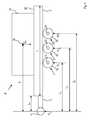
- FIG. 2shows the central axle trailer 8 in side view with further details. Visible are wheels 12 , 22 of the first and the second vehicle axle 1 , 2 fastened to the respective axle rods 13 , 23 . Also shown is the trailer structure 3 with a loading surface 30 . A load 31 is arranged on the loading surface 30 . Also visible is the trailer coupling 4 connected via the coupling rod 5 to the trailer structure 3 .
- G mis the weight force occurring as a result of the mass m of the load 31 relative to a center of gravity 32 of the load 31 .
- F sis the supporting load on the trailer coupling 4 .
- F 1is the axle load of the first axle 1 .
- F 2is the axle load of the second axle 2 .
- Lis the length of loading surface 30 in the longitudinal direction of the central axle trailer 8 .
- L 0is the spacing of the point of application of the supporting load F s from the front end of the loading surface 30 , which approximately corresponds to the effective length of the coupling rod 5 .
- L 1is the spacing between the point of application of the supporting load F s from the center of gravity 32 .
- L 2is the spacing between the points of application of the supporting load F s and the axle load F 1 of the first axle 1 .
- L 3is the spacing of the points of application of the supporting load F s and the axle load F 2 of the second axle 2 .
- the variables L, L 0 , L 1 , L 2 , L 3refer to the spacings to be measured in each case in the longitudinal direction of the central axle trailer 8 .
- the axle loads F 1 , F 2can, in this case, be determined from the detected pressure values of the first and the second pressure sensors 18 , 28 .
- the electronic control device 7can initially compare the axle loads F 1 , F 2 directly with one another to establish whether the current supporting load F s is outside a permitted supporting range. If the condition F 1 >F 2 is not fulfilled, it may be assumed that the current supporting load F s is outside a permitted supporting load range. In this case, the electronic control device 7 relieves the load from the first axle 1 , so as to increase the current supporting load F s thereby. To this end, the electronic control device 7 may, for example, reduce the quantity of air in the first pneumatic suspension circuit 15 , 16 , 17 , 18 , 19 or increase the quantity of air in the second pneumatic suspension circuit 25 , 26 , 27 , 28 , 29 or carry out both.
- the electronic control device 7determines a measurement of the current supporting load F s :
- F sF 1 ⁇ ( L 2 L 1 - 1 ) + F 2 ⁇ ( L 3 L 1 - 1 )
- the electronic control device 7compares the determined value of the current supporting load F s with predetermined limit values, which define a permitted supporting load range, for example 0.5 t as the lower limit value and 2 t as the upper limit value. If the supporting load range is not attained, the electronic control device 7 alters the quantity of air in at least one of the pneumatic suspension circuits in the previously described manner in order to bring the current supporting load F s again into the permitted supporting load range or at least closer thereto.
- the electronic control device 7determines the variable L 1 at least approximately according to the following relationship:
- mis the sum of F 1 and F 2 , divided by the gravitational acceleration g.
- m leeris the tare weight of the central axle trailer, i.e., the weight in the unloaded state
- m maxis the permitted maximum weight of the central axle trailer 8 .
- FIG. 3shows, with reference to three force/time diagrams arranged on top of one another, possible curves of the supporting load F s (upper diagram), the axle load F 1 of the first axle 1 (central diagram) and the axle load F 2 of the second axle 2 (lower diagram).
- the curvesare shown for the respective time periods A, B and C, which refer to different cases of adapting to the supporting load.
- a permitted supporting load range between a lower limit value F smin and an upper limit value F smaxis assumed.
- the maximum permitted axle load F 1 of the first axle 1 in the example shownis F 1max
- the maximum permitted axle load F 2 of the second axle 2is F 2max .
- the supporting load F sis initially below F smin .
- the electronic control device 7identifies this and relieves the load from the first axle 1 which in the central diagram in portion A may be identified as the axle load F 1 being reduced. This inevitably leads to a greater loading of the second axle 2 as may be seen in the lower diagram.
- the axle loads F 1 , F 2are in each case still below the permitted limit value F 1max , F 2max .
- the supporting load F sis moved into the permitted range, wherein this is sufficient to exceed the lower limit value F smin .
- the opposing caseis considered, in that the supporting load F s is initially too high, i.e., above the upper limit value F smax .
- the electronic control device 7identifies this and relieves the load from the second axle 2 , as may be seen in the lower diagram.
- the first axle 1is loaded to a greater extent, as shown in the central diagram in period B.
- the axle loads F 1 , F 2are also below the permitted axle load limit values F 1max , F 2max .
- the supporting load F sis moved approximately into the middle range of the permitted supporting load range.
- FIG. 4shows a central axle trailer 8 ′ in side view with further details.
- Central axle trailer 8 ′is similar to central axle trailer 8 of FIG. 2 with the addition of a third axle 33 .
- third axle 33 of central axle trailer 8 ′includes wheel 35 fastened to axle rod 34 .
- F 3is the axle load on third axle 33 .
- L 4is the spacing of the points of application of the supporting load F s and the axle load F 3 of third axle 33 .
Landscapes
- Engineering & Computer Science (AREA)
- Mechanical Engineering (AREA)
- Vehicle Body Suspensions (AREA)
Abstract
Description
Claims (11)
Applications Claiming Priority (3)
| Application Number | Priority Date | Filing Date | Title |
|---|---|---|---|
| DEDE102011118167.2 | 2011-11-10 | ||
| DE102011118167 | 2011-11-10 | ||
| DE102011118167ADE102011118167A1 (en) | 2011-11-10 | 2011-11-10 | Adjustment of the vertical load of a center-axle trailer |
Publications (2)
| Publication Number | Publication Date |
|---|---|
| US20130119637A1 US20130119637A1 (en) | 2013-05-16 |
| US9022404B2true US9022404B2 (en) | 2015-05-05 |
Family
ID=46799963
Family Applications (1)
| Application Number | Title | Priority Date | Filing Date |
|---|---|---|---|
| US13/652,953Active2032-10-17US9022404B2 (en) | 2011-11-10 | 2012-10-16 | Method and device for adjusting the supporting load of a central axle trailer |
Country Status (5)
| Country | Link |
|---|---|
| US (1) | US9022404B2 (en) |
| EP (1) | EP2591928B1 (en) |
| DE (1) | DE102011118167A1 (en) |
| ES (1) | ES2536241T3 (en) |
| PL (1) | PL2591928T3 (en) |
Cited By (8)
| Publication number | Priority date | Publication date | Assignee | Title |
|---|---|---|---|---|
| US20150251515A1 (en)* | 2014-03-05 | 2015-09-10 | World Trade Distribution, Inc. | Load leveling airbag suspension load sensors |
| US10160278B2 (en) | 2014-12-16 | 2018-12-25 | Aktv8 LLC | System and method for vehicle stabilization |
| US10259284B2 (en) | 2014-12-16 | 2019-04-16 | Aktv8 LLC | Electronically controlled vehicle suspension system and method of manufacture |
| US10315469B2 (en) | 2016-09-06 | 2019-06-11 | Aktv8 LLC | Tire management system and method |
| US10675936B2 (en) | 2014-12-16 | 2020-06-09 | Atv8 Llc | System and method for vehicle stabilization |
| US10766331B2 (en) | 2018-03-19 | 2020-09-08 | Ronald Jeremy Kliewer | Independent air suspension |
| US10870325B2 (en) | 2014-12-16 | 2020-12-22 | Aktv8 LLC | System and method for vehicle stabilization |
| US12151530B1 (en)* | 2023-06-21 | 2024-11-26 | GM Global Technology Operations LLC | Trailer suspension control systems and methods |
Families Citing this family (14)
| Publication number | Priority date | Publication date | Assignee | Title |
|---|---|---|---|---|
| DE102013002845A1 (en)* | 2013-02-20 | 2014-08-21 | Hydac System Gmbh | Device for controlling the drawbar load on multi-axle trailers |
| US10611206B2 (en)* | 2013-03-13 | 2020-04-07 | Hendrickson Usa, L.L.C. | Air suspension control system |
| CA2938609C (en) | 2014-03-04 | 2016-11-29 | Hendrickson Usa, L.L.C. | Parking brake interlock for automatic lift axle |
| DE102014206656B4 (en)* | 2014-04-07 | 2018-12-27 | Zf Friedrichshafen Ag | Their trailers |
| FR3031721B1 (en)* | 2015-01-19 | 2018-06-29 | Ecim | "TRAILER EQUIPPED WITH MEANS TO VERIFY THAT AN INBOARD LOAD IS BALANCED ON TWO AXLES AND ASSOCIATED METHOD" |
| DE102015115851A1 (en) | 2015-09-21 | 2017-03-23 | Knorr-Bremse Systeme für Nutzfahrzeuge GmbH | Method for operating a team |
| CN105235548A (en)* | 2015-10-23 | 2016-01-13 | 国网山东海阳市供电公司 | Electric driving system of electric automobile |
| SE1651302A1 (en) | 2016-10-04 | 2018-04-05 | Scania Cv Ab | A method for load determination of a vehicle, a vehicle load sensing system, a vehicle, a computer program and a compute r program product |
| FI127269B (en)* | 2017-03-07 | 2018-02-28 | Ak Usatrucks Oy | braking System |
| US20220089235A1 (en) | 2018-08-23 | 2022-03-24 | Hymer Business Development Gmbh | Caravan Having an Adjustable Tongue Load |
| DE102020102592A1 (en) | 2020-02-03 | 2021-08-05 | Audi Aktiengesellschaft | Method for operating a trailer combination and vehicle |
| DE102022131512A1 (en) | 2022-11-29 | 2024-05-29 | Zf Cv Systems Europe Bv | Method for controlling axle load distribution in a vehicle combination |
| WO2024181947A1 (en)* | 2023-02-28 | 2024-09-06 | Tirsan Treyler Sanayi̇ Ve Ti̇caret Anoni̇m Şi̇rketi̇ | Load transfer control system |
| EP4556264A1 (en)* | 2023-11-15 | 2025-05-21 | Volvo Truck Corporation | Trailer loading method |
Citations (38)
| Publication number | Priority date | Publication date | Assignee | Title |
|---|---|---|---|---|
| US2691420A (en)* | 1949-07-02 | 1954-10-12 | Gen Motors Corp | Fluid suspension system for vehicles |
| US3390895A (en)* | 1966-03-25 | 1968-07-02 | Sam C. Verdi | Auxiliary axle suspension |
| US3494632A (en)* | 1966-08-30 | 1970-02-10 | Boliden Ab | Means for controlling and regulating the load acting on vehicle axles |
| US3940167A (en)* | 1975-01-30 | 1976-02-24 | Young Ottawa, Inc. | Convertible trailer/rail car traction unit |
| US4103752A (en)* | 1977-01-10 | 1978-08-01 | General Trailer Company, Inc. | Fifth wheel scale apparatus |
| US4649369A (en)* | 1985-09-13 | 1987-03-10 | Partnership Of Robert Walker And Paul Lund | Apparatus for determining the position of a fifth wheel on a multi-axle vehicle |
| US4944526A (en)* | 1989-05-01 | 1990-07-31 | Allied-Signal Inc. | Air suspension system with load controlled liftable axle |
| US5035439A (en)* | 1989-05-02 | 1991-07-30 | Petrillo Patrick G | Method and means for providing rear steerability in a trailer assembly |
| DE19707210A1 (en) | 1997-02-24 | 1998-08-27 | Wabco Gmbh | Method of axle load dependent distribution of brake power in brake system of vehicles |
| DE19718258A1 (en) | 1997-04-30 | 1998-11-05 | Gerd Baer | Centre axle trailer and semi=trailer for unequal loading |
| US6240339B1 (en)* | 1999-02-26 | 2001-05-29 | Freightliner Llc | Vehicle rear axle load relief method and system |
| US20010007234A1 (en)* | 1999-02-19 | 2001-07-12 | Scheetz Technology, Inc. | Apparatus and method for real time adjustment of a fifth wheel associated with an agricultural machine |
| US20020180172A1 (en)* | 2001-06-01 | 2002-12-05 | Gottschalk Michael J. | Radio frequency-controlled axle/suspension lift system |
| US20030050749A1 (en)* | 2001-09-12 | 2003-03-13 | Cervantez Jesse W. | Direction/distance sensing vehicle function control system |
| US6572124B2 (en)* | 2001-02-28 | 2003-06-03 | Smc Corporation Of America | Lift axle control system |
| US20030111810A1 (en)* | 2001-12-19 | 2003-06-19 | Fulton R. Scott | Lift axle air pressure transfer control apparatus |
| US20030154798A1 (en)* | 2002-02-15 | 2003-08-21 | Ford Global Technologies, Inc. | Vehicle weight observation system |
| US20030155164A1 (en)* | 2001-12-28 | 2003-08-21 | Wheel Monitor Inc. | Axle weight distribution system |
| US20040178005A1 (en)* | 2003-03-15 | 2004-09-16 | Carlstrom Kevin R. | System and method for vehicle axle load measurement with hysteresis compensation and acceleration filter |
| US20050173892A1 (en)* | 2004-02-05 | 2005-08-11 | Terminello Leo F. | No-ramp trailer |
| DE102004003023A1 (en) | 2004-01-20 | 2005-08-11 | Crossmobil Gmbh | car trailers |
| US7000978B1 (en)* | 2004-08-20 | 2006-02-21 | Frank Messano | Thin-skin ultralight recreational vehicle body system |
| US7072763B2 (en)* | 2000-11-28 | 2006-07-04 | Arvinmeritor Technology, Llc | Intelligent load distribution system |
| US20070290461A1 (en)* | 2005-03-02 | 2007-12-20 | Volvo Lastvagnar Ab | Vehicle Suspension Arrangement |
| US20090024285A1 (en)* | 2005-12-27 | 2009-01-22 | Mack Trucks, Inc. | Fifth Wheel Slide Interlock |
| US20090069951A1 (en)* | 2004-10-29 | 2009-03-12 | Volvo Lastvagnar Ab | Method and a system for determining the load transferred from a semi-trailer to a first axle of a towing vehicle |
| DE102008003206A1 (en) | 2008-01-04 | 2009-07-09 | Wabco Gmbh | Axle load calculating method for non-load sensitive axle i.e. rear axle, of vehicle i.e. commercial motor vehicle, involves determining longitudinal slip value as difference slip, and calculating axle load of non-load sensitive axle |
| US7572988B1 (en)* | 2008-07-10 | 2009-08-11 | Morton Gregory D | Method for onboard vehicle weight measurement |
| US7735516B2 (en)* | 2006-05-16 | 2010-06-15 | Norgren Gt Development Corporation | Lift axle control module |
| US20100194143A1 (en)* | 2009-02-05 | 2010-08-05 | International Truck Intellectual Property Company, Llc | Proactive aerodynamic truck trailer shroud |
| US7872988B1 (en)* | 2009-09-21 | 2011-01-18 | Spirent Communications, Inc. | Methods and apparatuses for generating network test packets and parts of network test packets |
| US20110049837A1 (en)* | 2009-08-31 | 2011-03-03 | Andriy Hapyuk | System and method for determining whether the weight of a vehicle equipped with an air-ride suspension exceeds predetermined roadway weight limitations |
| DE102010037700A1 (en) | 2010-09-22 | 2012-03-22 | Schmitz Gotha Fahrzeugwerke Gmbh | Commercial motor vehicle tandem axle trailer i.e. semi-trailer, has control device deriving control value for pneumatic spring arrangement for drive and for adjusting pressures in air spring arrangements to desired pressure values |
| US8348297B2 (en)* | 2009-09-22 | 2013-01-08 | International Truck Intellectual Property Company, Llc | Slidably adjustable fifth wheel hitch assembly for a vehicle and control system for the same |
| US20130080078A1 (en)* | 2011-09-28 | 2013-03-28 | Alvin R. Wirthlin | System and method for gauging safe towing parameters |
| US20130079980A1 (en)* | 2011-09-23 | 2013-03-28 | Carl T. Vuk | Towed vehicle arrangement responsive to vehicle acceleration and deceleration |
| US20130140784A1 (en)* | 2011-12-02 | 2013-06-06 | Rodney P. Ehrlich | Biasing air suspension system for a trailer |
| US20130253814A1 (en)* | 2012-03-24 | 2013-09-26 | Alvin R. Wirthlin | System and Method for Gauging Safe Towing Parameters |
Family Cites Families (6)
| Publication number | Priority date | Publication date | Assignee | Title |
|---|---|---|---|---|
| DE19721130A1 (en)* | 1997-05-20 | 1998-11-26 | Claas Saulgau Gmbh | Agricultural multi-axle self-loading trailer |
| DE19801546A1 (en)* | 1998-01-16 | 1999-07-22 | Koegel Fahrzeugwerke Ag | Bogie angle altering process for multi-axle truck trailer |
| DE102004010561B4 (en)* | 2004-03-04 | 2022-09-08 | Zf Cv Systems Hannover Gmbh | Procedure for traction help control |
| DE102007015954A1 (en)* | 2007-04-03 | 2008-10-09 | Daimler Ag | Motor vehicle i.e. passenger car, has evaluation unit for detection of fluid pressure values and determination of total mass distribution of usable space and/or position of center of gravity of usable space |
| DE102008054044A1 (en)* | 2008-06-27 | 2009-12-31 | Wabco Gmbh | articulated lorry |
| EP2390121B1 (en)* | 2010-05-31 | 2013-03-06 | Schmitz Cargobull Gotha GmbH | Commercial vehicle trailer and control device for pneumatic spring assembly |
- 2011
- 2011-11-10DEDE102011118167Apatent/DE102011118167A1/ennot_activeWithdrawn
- 2012
- 2012-08-18ESES12005949.8Tpatent/ES2536241T3/enactiveActive
- 2012-08-18PLPL12005949Tpatent/PL2591928T3/enunknown
- 2012-08-18EPEP12005949.8Apatent/EP2591928B1/enactiveActive
- 2012-10-16USUS13/652,953patent/US9022404B2/enactiveActive
Patent Citations (40)
| Publication number | Priority date | Publication date | Assignee | Title |
|---|---|---|---|---|
| US2691420A (en)* | 1949-07-02 | 1954-10-12 | Gen Motors Corp | Fluid suspension system for vehicles |
| US3390895A (en)* | 1966-03-25 | 1968-07-02 | Sam C. Verdi | Auxiliary axle suspension |
| US3494632A (en)* | 1966-08-30 | 1970-02-10 | Boliden Ab | Means for controlling and regulating the load acting on vehicle axles |
| US3940167A (en)* | 1975-01-30 | 1976-02-24 | Young Ottawa, Inc. | Convertible trailer/rail car traction unit |
| US4103752A (en)* | 1977-01-10 | 1978-08-01 | General Trailer Company, Inc. | Fifth wheel scale apparatus |
| US4649369A (en)* | 1985-09-13 | 1987-03-10 | Partnership Of Robert Walker And Paul Lund | Apparatus for determining the position of a fifth wheel on a multi-axle vehicle |
| US4944526A (en)* | 1989-05-01 | 1990-07-31 | Allied-Signal Inc. | Air suspension system with load controlled liftable axle |
| US5035439A (en)* | 1989-05-02 | 1991-07-30 | Petrillo Patrick G | Method and means for providing rear steerability in a trailer assembly |
| DE19707210A1 (en) | 1997-02-24 | 1998-08-27 | Wabco Gmbh | Method of axle load dependent distribution of brake power in brake system of vehicles |
| DE19718258A1 (en) | 1997-04-30 | 1998-11-05 | Gerd Baer | Centre axle trailer and semi=trailer for unequal loading |
| US20010007234A1 (en)* | 1999-02-19 | 2001-07-12 | Scheetz Technology, Inc. | Apparatus and method for real time adjustment of a fifth wheel associated with an agricultural machine |
| US6240339B1 (en)* | 1999-02-26 | 2001-05-29 | Freightliner Llc | Vehicle rear axle load relief method and system |
| US7072763B2 (en)* | 2000-11-28 | 2006-07-04 | Arvinmeritor Technology, Llc | Intelligent load distribution system |
| US6572124B2 (en)* | 2001-02-28 | 2003-06-03 | Smc Corporation Of America | Lift axle control system |
| US20020180172A1 (en)* | 2001-06-01 | 2002-12-05 | Gottschalk Michael J. | Radio frequency-controlled axle/suspension lift system |
| US20030050749A1 (en)* | 2001-09-12 | 2003-03-13 | Cervantez Jesse W. | Direction/distance sensing vehicle function control system |
| US20030111810A1 (en)* | 2001-12-19 | 2003-06-19 | Fulton R. Scott | Lift axle air pressure transfer control apparatus |
| US6921100B2 (en)* | 2001-12-28 | 2005-07-26 | Wheel Monitor Inc. | Axle weight distribution system |
| US20030155164A1 (en)* | 2001-12-28 | 2003-08-21 | Wheel Monitor Inc. | Axle weight distribution system |
| US6829943B2 (en)* | 2002-02-15 | 2004-12-14 | Ford Global Technologies, Llc | Vehicle weight observation system |
| US20030154798A1 (en)* | 2002-02-15 | 2003-08-21 | Ford Global Technologies, Inc. | Vehicle weight observation system |
| US20040178005A1 (en)* | 2003-03-15 | 2004-09-16 | Carlstrom Kevin R. | System and method for vehicle axle load measurement with hysteresis compensation and acceleration filter |
| DE102004003023A1 (en) | 2004-01-20 | 2005-08-11 | Crossmobil Gmbh | car trailers |
| US20050173892A1 (en)* | 2004-02-05 | 2005-08-11 | Terminello Leo F. | No-ramp trailer |
| US7000978B1 (en)* | 2004-08-20 | 2006-02-21 | Frank Messano | Thin-skin ultralight recreational vehicle body system |
| US20090069951A1 (en)* | 2004-10-29 | 2009-03-12 | Volvo Lastvagnar Ab | Method and a system for determining the load transferred from a semi-trailer to a first axle of a towing vehicle |
| US20070290461A1 (en)* | 2005-03-02 | 2007-12-20 | Volvo Lastvagnar Ab | Vehicle Suspension Arrangement |
| US20090024285A1 (en)* | 2005-12-27 | 2009-01-22 | Mack Trucks, Inc. | Fifth Wheel Slide Interlock |
| US7735516B2 (en)* | 2006-05-16 | 2010-06-15 | Norgren Gt Development Corporation | Lift axle control module |
| DE102008003206A1 (en) | 2008-01-04 | 2009-07-09 | Wabco Gmbh | Axle load calculating method for non-load sensitive axle i.e. rear axle, of vehicle i.e. commercial motor vehicle, involves determining longitudinal slip value as difference slip, and calculating axle load of non-load sensitive axle |
| US7572988B1 (en)* | 2008-07-10 | 2009-08-11 | Morton Gregory D | Method for onboard vehicle weight measurement |
| US20100194143A1 (en)* | 2009-02-05 | 2010-08-05 | International Truck Intellectual Property Company, Llc | Proactive aerodynamic truck trailer shroud |
| US20110049837A1 (en)* | 2009-08-31 | 2011-03-03 | Andriy Hapyuk | System and method for determining whether the weight of a vehicle equipped with an air-ride suspension exceeds predetermined roadway weight limitations |
| US7872988B1 (en)* | 2009-09-21 | 2011-01-18 | Spirent Communications, Inc. | Methods and apparatuses for generating network test packets and parts of network test packets |
| US8348297B2 (en)* | 2009-09-22 | 2013-01-08 | International Truck Intellectual Property Company, Llc | Slidably adjustable fifth wheel hitch assembly for a vehicle and control system for the same |
| DE102010037700A1 (en) | 2010-09-22 | 2012-03-22 | Schmitz Gotha Fahrzeugwerke Gmbh | Commercial motor vehicle tandem axle trailer i.e. semi-trailer, has control device deriving control value for pneumatic spring arrangement for drive and for adjusting pressures in air spring arrangements to desired pressure values |
| US20130079980A1 (en)* | 2011-09-23 | 2013-03-28 | Carl T. Vuk | Towed vehicle arrangement responsive to vehicle acceleration and deceleration |
| US20130080078A1 (en)* | 2011-09-28 | 2013-03-28 | Alvin R. Wirthlin | System and method for gauging safe towing parameters |
| US20130140784A1 (en)* | 2011-12-02 | 2013-06-06 | Rodney P. Ehrlich | Biasing air suspension system for a trailer |
| US20130253814A1 (en)* | 2012-03-24 | 2013-09-26 | Alvin R. Wirthlin | System and Method for Gauging Safe Towing Parameters |
Cited By (11)
| Publication number | Priority date | Publication date | Assignee | Title |
|---|---|---|---|---|
| US20150251515A1 (en)* | 2014-03-05 | 2015-09-10 | World Trade Distribution, Inc. | Load leveling airbag suspension load sensors |
| US9834055B2 (en)* | 2014-03-05 | 2017-12-05 | World Trade Distribution, Inc. | Load leveling airbag suspension load sensors |
| US10160278B2 (en) | 2014-12-16 | 2018-12-25 | Aktv8 LLC | System and method for vehicle stabilization |
| US10259284B2 (en) | 2014-12-16 | 2019-04-16 | Aktv8 LLC | Electronically controlled vehicle suspension system and method of manufacture |
| US10675936B2 (en) | 2014-12-16 | 2020-06-09 | Atv8 Llc | System and method for vehicle stabilization |
| US10870325B2 (en) | 2014-12-16 | 2020-12-22 | Aktv8 LLC | System and method for vehicle stabilization |
| US10882374B2 (en) | 2014-12-16 | 2021-01-05 | Aktv 8 Llc | Electronically controlled vehicle suspension system and method of manufacture |
| US10315469B2 (en) | 2016-09-06 | 2019-06-11 | Aktv8 LLC | Tire management system and method |
| US10688836B2 (en) | 2016-09-06 | 2020-06-23 | Aktv8 LLC | Tire management system and method |
| US10766331B2 (en) | 2018-03-19 | 2020-09-08 | Ronald Jeremy Kliewer | Independent air suspension |
| US12151530B1 (en)* | 2023-06-21 | 2024-11-26 | GM Global Technology Operations LLC | Trailer suspension control systems and methods |
Also Published As
| Publication number | Publication date |
|---|---|
| EP2591928A3 (en) | 2014-01-29 |
| DE102011118167A1 (en) | 2013-05-16 |
| EP2591928A2 (en) | 2013-05-15 |
| PL2591928T3 (en) | 2015-07-31 |
| EP2591928B1 (en) | 2015-02-25 |
| US20130119637A1 (en) | 2013-05-16 |
| ES2536241T3 (en) | 2015-05-21 |
Similar Documents
| Publication | Publication Date | Title |
|---|---|---|
| US9022404B2 (en) | Method and device for adjusting the supporting load of a central axle trailer | |
| US8188385B2 (en) | Determination of the mass of a vehicle | |
| US20180065603A1 (en) | Trailer braking system and controller | |
| US7572988B1 (en) | Method for onboard vehicle weight measurement | |
| US20080269986A1 (en) | System and Method for Controlling the Axle Load Split Ratio on a Vehicle With Two Front Axles | |
| AU2007248893B2 (en) | Vehicle stability control system with multiple sensitivities | |
| SE529962C2 (en) | Axle load control system and method for a load-carrying truck | |
| JP2002054983A (en) | Measurement of loading state of automobile | |
| CN108202744A (en) | Automated vehicle control with payload compensation | |
| CN105163980B (en) | Method of Determining When the Deck of a Towing Machine Is Empty | |
| JP2009535252A (en) | Air storage system for air suspension system in heavy vehicles | |
| US6819980B2 (en) | Method for the avoidance of rollover phenomena in semitrailers | |
| US9180845B2 (en) | Passenger car transport | |
| US12420755B2 (en) | Apparatus and method for determining a road friction | |
| EP2148794B1 (en) | Tilt angle sensor and apparatus | |
| WO2014046601A1 (en) | Method and system for level adjustment of vehicle configuration | |
| US20230128284A1 (en) | Methods and systems for estimating the current weight of commercial vehicles | |
| EP2294370B1 (en) | Method and device for controlling a function of a vehicle. | |
| EP3548317B1 (en) | Trailer mode estimation method from rear suspension load |
Legal Events
| Date | Code | Title | Description |
|---|---|---|---|
| AS | Assignment | Owner name:WABCO GMBH, GERMANY Free format text:ASSIGNMENT OF ASSIGNORS INTEREST;ASSIGNORS:RISSE, RAINER;STENDER, AXEL;REEL/FRAME:029565/0633 Effective date:20121030 | |
| STCF | Information on status: patent grant | Free format text:PATENTED CASE | |
| MAFP | Maintenance fee payment | Free format text:PAYMENT OF MAINTENANCE FEE, 4TH YEAR, LARGE ENTITY (ORIGINAL EVENT CODE: M1551); ENTITY STATUS OF PATENT OWNER: LARGE ENTITY Year of fee payment:4 | |
| AS | Assignment | Owner name:ZF CV SYSTEMS HANNOVER GMBH, GERMANY Free format text:CHANGE OF NAME;ASSIGNOR:WABCO GMBH;REEL/FRAME:059819/0146 Effective date:20200915 Owner name:ZF CV SYSTEMS EUROPE BV, BELGIUM Free format text:ASSIGNMENT OF ASSIGNORS INTEREST;ASSIGNOR:ZF CV SYSTEMS HANNOVER GMBH;REEL/FRAME:059540/0990 Effective date:20220210 | |
| MAFP | Maintenance fee payment | Free format text:PAYMENT OF MAINTENANCE FEE, 8TH YEAR, LARGE ENTITY (ORIGINAL EVENT CODE: M1552); ENTITY STATUS OF PATENT OWNER: LARGE ENTITY Year of fee payment:8 |