US9020683B1 - Method and system to detect faults of a trailer electrical system - Google Patents
Method and system to detect faults of a trailer electrical systemDownload PDFInfo
- Publication number
- US9020683B1 US9020683B1US11/774,153US77415307AUS9020683B1US 9020683 B1US9020683 B1US 9020683B1US 77415307 AUS77415307 AUS 77415307AUS 9020683 B1US9020683 B1US 9020683B1
- Authority
- US
- United States
- Prior art keywords
- mode
- current
- current operating
- diagnostic system
- trailer
- Prior art date
- Legal status (The legal status is an assumption and is not a legal conclusion. Google has not performed a legal analysis and makes no representation as to the accuracy of the status listed.)
- Expired - Fee Related, expires
Links
Images


Classifications
- B—PERFORMING OPERATIONS; TRANSPORTING
- B60—VEHICLES IN GENERAL
- B60W—CONJOINT CONTROL OF VEHICLE SUB-UNITS OF DIFFERENT TYPE OR DIFFERENT FUNCTION; CONTROL SYSTEMS SPECIALLY ADAPTED FOR HYBRID VEHICLES; ROAD VEHICLE DRIVE CONTROL SYSTEMS FOR PURPOSES NOT RELATED TO THE CONTROL OF A PARTICULAR SUB-UNIT
- B60W50/00—Details of control systems for road vehicle drive control not related to the control of a particular sub-unit, e.g. process diagnostic or vehicle driver interfaces
- B60W50/02—Ensuring safety in case of control system failures, e.g. by diagnosing, circumventing or fixing failures
- B60W50/0205—Diagnosing or detecting failures; Failure detection models
- B—PERFORMING OPERATIONS; TRANSPORTING
- B62—LAND VEHICLES FOR TRAVELLING OTHERWISE THAN ON RAILS
- B62D—MOTOR VEHICLES; TRAILERS
- B62D59/00—Trailers with driven ground wheels or the like
- H—ELECTRICITY
- H05—ELECTRIC TECHNIQUES NOT OTHERWISE PROVIDED FOR
- H05B—ELECTRIC HEATING; ELECTRIC LIGHT SOURCES NOT OTHERWISE PROVIDED FOR; CIRCUIT ARRANGEMENTS FOR ELECTRIC LIGHT SOURCES, IN GENERAL
- H05B47/00—Circuit arrangements for operating light sources in general, i.e. where the type of light source is not relevant
- H05B47/20—Responsive to malfunctions or to light source life; for protection
- B—PERFORMING OPERATIONS; TRANSPORTING
- B60—VEHICLES IN GENERAL
- B60W—CONJOINT CONTROL OF VEHICLE SUB-UNITS OF DIFFERENT TYPE OR DIFFERENT FUNCTION; CONTROL SYSTEMS SPECIALLY ADAPTED FOR HYBRID VEHICLES; ROAD VEHICLE DRIVE CONTROL SYSTEMS FOR PURPOSES NOT RELATED TO THE CONTROL OF A PARTICULAR SUB-UNIT
- B60W2300/00—Indexing codes relating to the type of vehicle
- B60W2300/14—Tractor-trailers, i.e. combinations of a towing vehicle and one or more towed vehicles, e.g. caravans; Road trains
- B—PERFORMING OPERATIONS; TRANSPORTING
- B60—VEHICLES IN GENERAL
- B60W—CONJOINT CONTROL OF VEHICLE SUB-UNITS OF DIFFERENT TYPE OR DIFFERENT FUNCTION; CONTROL SYSTEMS SPECIALLY ADAPTED FOR HYBRID VEHICLES; ROAD VEHICLE DRIVE CONTROL SYSTEMS FOR PURPOSES NOT RELATED TO THE CONTROL OF A PARTICULAR SUB-UNIT
- B60W2540/00—Input parameters relating to occupants
- B60W2540/12—Brake pedal position
- H—ELECTRICITY
- H02—GENERATION; CONVERSION OR DISTRIBUTION OF ELECTRIC POWER
- H02H—EMERGENCY PROTECTIVE CIRCUIT ARRANGEMENTS
- H02H9/00—Emergency protective circuit arrangements for limiting excess current or voltage without disconnection
Definitions
- the present teachingsrelate to methods and systems for detecting faults of a trailer electrical system and more particularly to methods and systems for detecting an open lamp filament of a trailer electrical system.
- the trailer electrical systemcan include, for example, a right turn/stop lamp and a left/turn stop lamp.
- a right turn/stop lampWhen either of the lamps fail due to, for example, an open filament, the vehicle operator is most often unaware of the failure. It is not until other bystanders notify the operator or the operator performs an inspection while the trailer is in a parked condition that the operator becomes aware of the failure.
- the present teachingsgenerally include a diagnostic system for diagnosing faults in a trailer electrical system.
- the diagnostic systemgenerally includes a mode determination module that determines a current operating mode to be one of a sleep mode, a normal mode, a situational awareness mode, and an adaptive calibration mode.
- a first mode moduleoperates when the current operating mode is the normal mode and during operation, diagnoses an open circuit fault of the trailer electrical system based on a comparison of a current load on the trailer electrical system and an average load.
- FIG. 1is a block diagram illustrating a vehicle including a trailer diagnostic system in accordance with various aspects of the present teachings.
- FIG. 2is a block diagram illustrating an exemplary trailer diagnostic system implemented in a vehicle in accordance with various aspects of the present teachings.
- FIG. 3is a data flow diagram illustrating an exemplary trailer diagnostic system in accordance with various aspects of the present teachings.
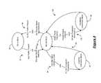
- FIG. 4is a state transition diagram illustrating exemplary modes and transitions of the mode determination module of the trailer diagnostic system in accordance with various aspects of the present teachings.
- FIG. 5is a process flow diagram illustrating an exemplary method that can be performed while in the sleep mode of the trailer diagnostic system in accordance with various aspects of the present teachings.
- FIG. 6is a process flow diagram illustrating an exemplary method that can be performed while in a situational awareness mode of the trailer diagnostic system in accordance with various aspects of the present teachings.
- FIG. 7is a process flow diagram illustrating an exemplary method that can be performed while in an adaptive calibration mode of the trailer diagnostic system in accordance with various aspects of the present teachings.
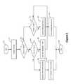
- FIG. 8is a process flow diagram illustrating an exemplary method that can be performed while in a normal mode of the trailer diagnostic system in accordance with various aspects of the present teachings.
- module, control module, component and/or devicecan refer to one or more of the following: an application specific integrated circuit (ASIC), an electronic circuit, a processor (shared, dedicated or group) and memory that executes one or more software or firmware programs, a combinational logic circuit and/or other suitable mechanical, electrical or electro-mechanical components that can provide the described functionality and/or combinations thereof.
- ASICapplication specific integrated circuit
- processorshared, dedicated or group
- memorythat executes one or more software or firmware programs
- a vehicle shown generally at 10can include a trailer diagnostic system. It can be appreciated in light of the disclosure that the trailer diagnostic system can be applicable to various trailer systems. For example, a similar trailer diagnostic system can be used for tractors and trailers. For exemplary purposes, various aspects of the trailer diagnostic system will be discussed in the context of the vehicle 10 and a trailer 12 .
- the vehicle 10can include at least one vehicle electrical connector 16 that can couple to or be near a rear end of the vehicle 10 .
- the vehicle electrical connector 16can include a plurality of output pins that can mate with a plurality of receptacles, or electrical terminals of a trailer electrical connector 18 .
- the trailer electrical connector 18can be connected and disconnected to the vehicle electrical connector 16 .
- the vehicle electrical connector 16can provide current from a power source 28 to the trailer electrical connector 18 .
- the trailer electrical connector 18can provide current to various components of the electrical system 19 of the trailer 12 via a wiring harness 20 .
- Such electrical system 19can include, but is not limited to, a right turn/stop lamp (RTL), a left turn/stop lamp (LTL), and a braking system.
- the trailer diagnostic systemcan include a connector circuit 22 that can diagnose open filaments as well as other electrical faults of the electrical system 19 .
- the connector circuit 22can communicate the faults to a vehicle control module 24 and can receive vehicle commands from the vehicle control module 24 via a communication bus 26 .
- the vehicle control module 24can generate a fault signal to alert a vehicle operator of the fault based on the communicated fault.
- FIG. 2a block diagram illustrates an exemplary diagnostic system implemented in the vehicle 10 in accordance with various aspects of the present teachings.
- one or more switches 30 , 32 , and 34such as a metal-oxide-semiconductor field-effect transistor (MOSFET, simplified as FET hereafter), can be controlled by a control module 36 to allow current to flow from the power source 28 to the electrical system 19 .
- the electrical system 19can include, but is not limited to, a RTL 38 , a LTL 40 , and one or more other electrical loads 42 .
- the control module 36can control the state of the switches 30 , 32 , and 34 via control signals 44 , 46 , and 48 respectively, based on vehicle commands 50 received from the vehicle control module 24 ( FIG. 1 ) and/or discrete input signals 52 received from hardwire inputs (not shown).
- the control module 36can diagnose faults of each of the electrical systems 38 , 40 , and 42 based on a flow of current through each of the corresponding circuits.
- Current sensors 54 , 56 , and 58can generate current signals 60 , 62 , and 64 respectively, for each circuit.
- the control module 36can diagnose at least one of an open circuit fault, a circuit error, and an over-load fault based on the current signals 60 , 62 , and 64 and can generate a fault message 66 accordingly.
- a data flow diagramillustrates an exemplary trailer diagnostic system that can be implemented within the control module 36 in accordance with various aspects of the present teachings.
- various aspects of trailer diagnostic systems in accordance with the present teachingscan include any number of sub-modules embedded within the control module 36 .
- the sub-modulescan be combined and/or further partitioned to similarly diagnose the electrical system 19 .
- Inputs to the systemcan be sensed from the vehicle 10 , received from other control modules, such as the vehicle control module 24 ( FIG. 1 ), and/or determined by other sub-modules (not shown) within the control module 36 .
- the control module 36 of FIG. 3can include a mode determination module 70 , a sleep mode module 72 , a normal mode module 74 , an adaptive calibration (AC) mode module 76 , and a situational awareness (SA) mode module 78 .
- ACadaptive calibration
- SAsituational awareness
- the mode determination module 70can receive as input the vehicle command 50 , the discrete input signals 52 , an adaptive calibration (AC) status 80 , and/or a situational awareness (SA) status 82 .
- the mode determination module 70can determine an active mode 84 to be at least one of a normal mode, a sleep mode, a situational awareness (SA) mode, and an adaptive calibration (AC) mode based on the inputs 50 , 52 , 80 and/or 82 and predefined transition conditions.
- the mode determination module 70can transition the active mode 84 between a sleep mode 88 and a normal mode 86 and between a normal mode 86 and a SA mode 90 and an AC mode 92 based on predefined transition conditions 93 , 94 , 96 , 98 , 100 , and 102 .
- the mode determination module 70can transition the active mode 84 from the sleep mode 88 to the normal mode 86 when the vehicle commands 50 or the discrete input signals 52 are present as shown at 93 .
- the mode determination module 70can transition the active mode 84 from the normal mode 86 to the SA mode 90 when the vehicle commands 50 or the discrete input signals 52 indicate that the brake pedal has been depressed or the hazard signals are requested and the SA status 82 indicates that the SA mode 90 has not completed successfully as shown at 100 .
- the mode determination module 70can transition the active mode 84 from the SA mode 90 back to the normal mode 86 when the SA mode completes as shown at 102 .
- the mode determination module 70can transition the active mode 84 from the normal mode 86 to the AC mode 92 when the vehicle commands 50 or the discrete input signals 52 request a circuit to be activated and the AC status 80 indicates that the AC mode has not completed successfully as shown at 96 .
- the mode determination module 70can transition the active mode 84 from the AC mode 92 back to the normal mode 86 when the AC mode completes as shown at 98 .
- the mode determination module 70can transition the active mode 84 from the normal mode 86 back to the sleep mode 88 when there are no vehicle commands 50 received and no discrete input signals 52 detected as shown at 94 .
- the transition condition 94can be based on inactivity for a predetermined time period.
- the sleep mode module 72can receive as input the active mode 84 .
- the active mode 84indicates that the current mode is the sleep mode 88 ( FIG. 4 )
- the sleep mode module 72can deactivate the switches 30 , 32 , and 34 and other circuitry to minimize the consumption of power from the power source 28 .
- the sleep mode module 72can clear all stored values relating to the diagnosing of the electrical system 19 ( FIG. 1 ), as will be discussed further.
- the SA mode module 78can receive as input the active mode 84 and the current signals 60 and 62 .
- the SA mode module 78can activate the switches 30 and 32 via control signals 44 and 46 to permit the flow of current from the power source 28 ( FIG. 2 ) to the RTL 38 and the LTL 40 , respectively.
- the SA mode module 78can then monitor the current signals 60 and 62 to determine whether the circuit for the respective electrical system 19 ( FIG. 2 ) is open or closed. Based on whether the circuits are open or closed, the SA mode module 78 can set the SA status 82 to indicate whether the monitoring has completed successfully or completed unsuccessfully and can selectively generate a fault message 66 a.
- the AC mode module 76can receive as input the active mode 84 and the current signals 60 , 62 , or 64 .
- the AC mode module 76can generate the appropriate control signal 44 , 46 , or 48 to activate the switches 30 , 32 , or 34 ( FIG. 2 ); can measure a load for the active circuit based on the current signals 60 , 62 , or 64 ; and can determine an average load 106 over a predetermined time period.
- the AC mode module 76then can store the average load 106 for future comparisons. Once the average load 106 is computed, the AC mode module 76 can set the AC status 80 to indicate whether the adaptive calibration has completed successfully or unsuccessfully.
- the normal mode module 74can receive as input the active mode 84 , the SA status 82 , the AC status 80 , the current signal 60 , 62 , or 64 , and the average load 106 .
- the normal mode module 74can generate the appropriate control signal 44 , 46 , or 48 and compare a current load to the average load 106 to determine whether an open filament/circuit fault or an over-load fault has occurred.
- the normal mode module 74can generate an over-load fault message 66 b and/or can open filament/circuit fault message 66 c.
- a process flow diagramillustrates a sleep mode method that can be performed by the sleep mode module 72 implemented in accordance with FIG. 3 .
- the methodcan be scheduled to run when the active mode 84 ( FIG. 3 ) becomes the sleep mode 88 ( FIG. 4 ).
- the order of operation within the methodis not limited to the sequential execution as illustrated in FIG. 5 , but may be performed in one or more varying orders as applicable and in accordance with the present teachings.
- the methodmay begin at 200 .
- the stored values, such as the average load 106 , the AC status 80 , and the SA status 82can be cleared at 210 .
- the switches 30 , 32 , and 34can be deactivated and other circuitry can be controlled OFF at 220 .
- the methodmay end at 230 .
- a process flow diagramillustrates a situational awareness mode method that can be performed by the SA mode module 78 , implemented in accordance with FIG. 3 .
- the methodcan be scheduled to run when the active mode 84 ( FIG. 3 ) becomes the SA mode 90 ( FIG. 4 ).
- the order of operation within the methodis not limited to the sequential execution as illustrated in FIG. 6 , but may be performed in one or more varying orders as applicable and in accordance with the present teachings.
- the methodmay begin at 300 .
- a first circuit(circuit 1), for example, relating to the RTL 38 ( FIG. 2 ) and a second circuit (circuit 2), for example, relating to the LTL 40 ( FIG. 2 ) can be activated at 310 .
- the first circuitcan be evaluated at 320 . If the first circuit is open at 320 , the second circuit can be evaluated at 330 . If the second circuit is open at 330 , then both circuits are open and it can be assumed that the trailer 12 ( FIG. 1 ) is not electrically connected to the vehicle 10 ( FIG. 1 ) at 340 .
- the SA status 82( FIG. 3 ) can be set to indicate the mode has completed unsuccessfully at 350 .
- the second circuitis not open (e.g., closed) at 330 , then the first circuit is open and the second circuit is closed, and a fault message 66 a ( FIG. 3 ) can be logged for circuit 1 at 360 and the SA status 82 ( FIG. 3 ) can be set to indicate the mode has completed successfully at 370 .
- the second circuitcan be evaluated at 380 . If the second circuit is open at 380 , then the first circuit is closed and the second circuit is open, a fault message 66 a ( FIG. 3 ) can be logged for circuit 2 at 390 and the SA status 82 ( FIG. 3 ) can be set to indicate the mode has completed successfully at 370 . Otherwise, if the second circuit is not open (e.g., closed) at 380 , then both circuits are closed. The SA status 82 ( FIG. 3 ) can be set to indicate the mode has completed successfully at 370 . The method may end at 394 .
- a process flow diagramillustrates an adaptive calibration mode method that can be performed by the AC mode module 76 , implemented in accordance with FIG. 3 .
- the methodcan be scheduled to run when the active mode 84 ( FIG. 3 ) becomes the AC mode 92 ( FIG. 4 ).
- the order of operation within the methodis not limited to the sequential execution as illustrated in FIG. 7 , but may be performed in one or more varying orders as applicable and in accordance with the present teachings.
- the methodmay begin at 400 .
- the circuitcan be activated at 410 .
- the current for the active circuitcan be measured at 420 .
- the average loadis determinable at 430
- the average load 106 ( FIG. 3 ) over a predetermined time periodcan be estimated and stored at 440 .
- the AC status 80( FIG. 3 ) can be set to indicate that the AC mode has completed successfully at 450 .
- the methodmay end at 470 .
- the AC status 80FIG. 3
- the AC status 80can be set to indicate that the AC mode has completed unsuccessfully at 460 and the method may end at 470 .
- a process flow diagramillustrates a normal mode method that can be performed by the normal mode module 74 , implemented in accordance with FIG. 3 .
- the methodcan be scheduled to run when the active mode 84 ( FIG. 3 ) becomes the normal mode 86 ( FIG. 4 ).
- the order of operation within the methodis not limited to the sequential execution as illustrated in FIG. 8 , but may be performed in one or more varying orders as applicable and in accordance with the present teachings.
- the methodmay begin at 500 .
- the SA status 82( FIG. 3 ) and the AC status 80 ( FIG. 3 ) can be evaluated at 510 and 520 . If the SA status 82 ( FIG. 3 ) indicates that the SA mode has not completed successfully at 510 , the vehicle command or discrete input can be evaluated to see if the brake pedal has been depressed or there is a request for a hazard signal at 530 . If the brake pedal has not been depressed and there is no request for a hazard signal at 530 , the appropriate switch 30 , 32 , or 34 ( FIG. 2 ) can be activated at 540 if not already active. Otherwise, if the brake pedal has been depressed or there is a request for a hazard signal at 530 , the method may end at 592 , for example, to allow the SA mode to complete.
- the methodmay end at 592 , for example, to allow the AC mode to complete. Otherwise, if the AC status 80 ( FIG. 3 ) indicates that the AC mode has completed at 510 , the switch 30 , 32 , or 34 ( FIG. 2 ) can be activated at 540 if not already active.
- the load for the circuit with the active switch 30 , 32 , or 34 ( FIG. 2 )can be estimated at 550 and can be evaluated at 560 . If the load is within a predetermined range of the stored average 106 ( FIG. 3 ) at 560 , the circuit is operating as intended and the method may end at 592 . Otherwise, if the load is outside of the predetermined range of the average 106 ( FIG. 3 ) at 560 , the load can be further evaluated at 570 .
- the switch 30 , 32 , or 34( FIG. 2 ) is deactivated at 580 and the over-load fault message 66 b ( FIG. 3 ) can be logged at 590 to indicate that the circuit has been deactivated to protect the circuit from over-load. Otherwise, if the load is less than the predetermined range at 570 , the fault message 66 c ( FIG. 3 ) can be logged to indicate an open filament for that circuit at 562 . The method may end at 592 .
Landscapes
- Engineering & Computer Science (AREA)
- Transportation (AREA)
- Mechanical Engineering (AREA)
- Automation & Control Theory (AREA)
- Chemical & Material Sciences (AREA)
- Combustion & Propulsion (AREA)
- Human Computer Interaction (AREA)
- Testing Of Short-Circuits, Discontinuities, Leakage, Or Incorrect Line Connections (AREA)
Abstract
Description
Claims (25)
Priority Applications (1)
| Application Number | Priority Date | Filing Date | Title |
|---|---|---|---|
| US11/774,153US9020683B1 (en) | 2007-07-06 | 2007-07-06 | Method and system to detect faults of a trailer electrical system |
Applications Claiming Priority (1)
| Application Number | Priority Date | Filing Date | Title |
|---|---|---|---|
| US11/774,153US9020683B1 (en) | 2007-07-06 | 2007-07-06 | Method and system to detect faults of a trailer electrical system |
Publications (1)
| Publication Number | Publication Date |
|---|---|
| US9020683B1true US9020683B1 (en) | 2015-04-28 |
Family
ID=52987077
Family Applications (1)
| Application Number | Title | Priority Date | Filing Date |
|---|---|---|---|
| US11/774,153Expired - Fee RelatedUS9020683B1 (en) | 2007-07-06 | 2007-07-06 | Method and system to detect faults of a trailer electrical system |
Country Status (1)
| Country | Link |
|---|---|
| US (1) | US9020683B1 (en) |
Cited By (8)
| Publication number | Priority date | Publication date | Assignee | Title |
|---|---|---|---|---|
| US20160035156A1 (en)* | 2013-08-13 | 2016-02-04 | Paul Leonard Andrus | Intelligent Towing Plug |
| US20160152216A1 (en)* | 2014-12-01 | 2016-06-02 | Bendix Commercial Vehicle Systems Llc | Method, System and Controller for Determining Whether to Brake a Trailer |
| US20160303935A1 (en)* | 2013-09-20 | 2016-10-20 | Lamrok Outdoor Products LLC | Connector device for providing access to electrical power |
| US10068393B2 (en) | 2013-08-13 | 2018-09-04 | Prairie Innovators Llc | Intelligent towing plug |
| CN111038261A (en)* | 2019-12-12 | 2020-04-21 | 联合汽车电子有限公司 | Trailer protection method |
| US20210179119A1 (en)* | 2019-12-16 | 2021-06-17 | Hyundai Motor Company | Vehicle and method of controlling the same |
| CN113156330A (en)* | 2021-04-19 | 2021-07-23 | 东风柳州汽车有限公司 | Automatic detection method, device and system for trailer steering lamp |
| US12427996B1 (en)* | 2021-09-27 | 2025-09-30 | Grote Industries, Inc. | Wireless vehicle communication system |
Citations (21)
| Publication number | Priority date | Publication date | Assignee | Title |
|---|---|---|---|---|
| US2743431A (en) | 1951-02-14 | 1956-04-24 | Glenn H Wright | Condition indicators for lighting systems of trucks and trailers |
| US3840852A (en) | 1973-01-12 | 1974-10-08 | R Schwellenbach | Device for monitoring the operation of directional signal lamps and other electrical components |
| US3987424A (en) | 1974-04-22 | 1976-10-19 | Stewart-Warner Corporation | Bulb outage warning system |
| US4291302A (en) | 1978-11-13 | 1981-09-22 | King Gordon A | Lamp monitoring circuits |
| US5144282A (en) | 1991-01-18 | 1992-09-01 | General Motors Corporation | Adaptive lamp monitor with first and second comparison rates |
| US5254971A (en) | 1991-01-18 | 1993-10-19 | General Motors Corporation | Adaptive lamp monitor using capacitors and switches |
| US5515028A (en) | 1994-02-04 | 1996-05-07 | Dittmar; Norman R. | Vehicular lamp status display system |
| US5604439A (en) | 1993-04-15 | 1997-02-18 | Walkington; Clifford L. | Tractor/trailer lamp circuit continuity test device |
| US5886543A (en) | 1994-12-22 | 1999-03-23 | U.S. Philips Corporation | Power semiconductor switch having a load open-circuit detection circuit |
| US6157296A (en) | 1997-09-02 | 2000-12-05 | Harness System Technologies Research, Ltd. | Lamp burnout detecting unit with branch connection function |
| US6466028B1 (en)* | 2001-04-23 | 2002-10-15 | Transcommunications, Inc. | Trailer tether sensor circuit |
| US6525654B1 (en) | 1998-09-02 | 2003-02-25 | Nighthawk (Tlm) Limited | Vehicle electrical circuit failure monitor |
| US6535113B1 (en) | 1998-09-10 | 2003-03-18 | Dennis R. Gravolin | Electrical tell tale system for trailers |
| US6713966B2 (en) | 2002-05-21 | 2004-03-30 | Yazaki North America, Inc. | Event and arc detection in lamps |
| US6720883B2 (en) | 2001-05-03 | 2004-04-13 | Electronic Controls Company | Warning device status circuit including a status output device |
| US6788195B1 (en) | 2002-08-09 | 2004-09-07 | Osborne Coinage Company | Light monitor |
| US7046132B2 (en) | 2003-11-12 | 2006-05-16 | Emergency Technology, Inc. | Lamp monitor and method for operating a lamp monitor |
| US7124003B1 (en)* | 2004-09-24 | 2006-10-17 | Fifth Wheel Diagnostics, Llc | Diagnostics device for testing electrical circuits of a recreational vehicle |
| US7403100B2 (en)* | 2003-05-02 | 2008-07-22 | Volvo Lastvagnar Ab | Detection of trailer presence and type by means of current detection |
| US20080204033A1 (en)* | 2007-02-28 | 2008-08-28 | Stmicroelectronics, Inc. | Integrated Circuit and Method for Monitoring and Controlling Power and for Detecting Open Load State |
| US7777495B2 (en)* | 2005-09-16 | 2010-08-17 | Volvo Lastvagnar Ab | Method and a device for detecting signal lamps in a vehicle |
- 2007
- 2007-07-06USUS11/774,153patent/US9020683B1/ennot_activeExpired - Fee Related
Patent Citations (24)
| Publication number | Priority date | Publication date | Assignee | Title |
|---|---|---|---|---|
| US2743431A (en) | 1951-02-14 | 1956-04-24 | Glenn H Wright | Condition indicators for lighting systems of trucks and trailers |
| US3840852A (en) | 1973-01-12 | 1974-10-08 | R Schwellenbach | Device for monitoring the operation of directional signal lamps and other electrical components |
| US3987424A (en) | 1974-04-22 | 1976-10-19 | Stewart-Warner Corporation | Bulb outage warning system |
| US4068216A (en) | 1974-04-22 | 1978-01-10 | Stewart-Warner Corporation | Bulb outage warning system |
| US4291302A (en) | 1978-11-13 | 1981-09-22 | King Gordon A | Lamp monitoring circuits |
| US5144282A (en) | 1991-01-18 | 1992-09-01 | General Motors Corporation | Adaptive lamp monitor with first and second comparison rates |
| US5254971A (en) | 1991-01-18 | 1993-10-19 | General Motors Corporation | Adaptive lamp monitor using capacitors and switches |
| US5604439A (en) | 1993-04-15 | 1997-02-18 | Walkington; Clifford L. | Tractor/trailer lamp circuit continuity test device |
| US5515028A (en) | 1994-02-04 | 1996-05-07 | Dittmar; Norman R. | Vehicular lamp status display system |
| US5886543A (en) | 1994-12-22 | 1999-03-23 | U.S. Philips Corporation | Power semiconductor switch having a load open-circuit detection circuit |
| US6157296A (en) | 1997-09-02 | 2000-12-05 | Harness System Technologies Research, Ltd. | Lamp burnout detecting unit with branch connection function |
| US6525654B1 (en) | 1998-09-02 | 2003-02-25 | Nighthawk (Tlm) Limited | Vehicle electrical circuit failure monitor |
| US6535113B1 (en) | 1998-09-10 | 2003-03-18 | Dennis R. Gravolin | Electrical tell tale system for trailers |
| US6466028B1 (en)* | 2001-04-23 | 2002-10-15 | Transcommunications, Inc. | Trailer tether sensor circuit |
| US6720883B2 (en) | 2001-05-03 | 2004-04-13 | Electronic Controls Company | Warning device status circuit including a status output device |
| US7023353B2 (en) | 2001-05-03 | 2006-04-04 | Electronic Controls Company | Warning device status circuit including a status output device |
| US6713966B2 (en) | 2002-05-21 | 2004-03-30 | Yazaki North America, Inc. | Event and arc detection in lamps |
| US6788195B1 (en) | 2002-08-09 | 2004-09-07 | Osborne Coinage Company | Light monitor |
| US7403100B2 (en)* | 2003-05-02 | 2008-07-22 | Volvo Lastvagnar Ab | Detection of trailer presence and type by means of current detection |
| US7046132B2 (en) | 2003-11-12 | 2006-05-16 | Emergency Technology, Inc. | Lamp monitor and method for operating a lamp monitor |
| US7124003B1 (en)* | 2004-09-24 | 2006-10-17 | Fifth Wheel Diagnostics, Llc | Diagnostics device for testing electrical circuits of a recreational vehicle |
| US7777495B2 (en)* | 2005-09-16 | 2010-08-17 | Volvo Lastvagnar Ab | Method and a device for detecting signal lamps in a vehicle |
| US20080204033A1 (en)* | 2007-02-28 | 2008-08-28 | Stmicroelectronics, Inc. | Integrated Circuit and Method for Monitoring and Controlling Power and for Detecting Open Load State |
| US7904260B2 (en)* | 2007-02-28 | 2011-03-08 | Stmicroelectronics, Inc. | Integrated circuit and method for classification of electrical devices and short circuit protection |
Cited By (12)
| Publication number | Priority date | Publication date | Assignee | Title |
|---|---|---|---|---|
| US20160035156A1 (en)* | 2013-08-13 | 2016-02-04 | Paul Leonard Andrus | Intelligent Towing Plug |
| US9501877B2 (en)* | 2013-08-13 | 2016-11-22 | Prairie Innovators Llc | Intelligent towing plug |
| US10068393B2 (en) | 2013-08-13 | 2018-09-04 | Prairie Innovators Llc | Intelligent towing plug |
| US20160303935A1 (en)* | 2013-09-20 | 2016-10-20 | Lamrok Outdoor Products LLC | Connector device for providing access to electrical power |
| US20160152216A1 (en)* | 2014-12-01 | 2016-06-02 | Bendix Commercial Vehicle Systems Llc | Method, System and Controller for Determining Whether to Brake a Trailer |
| US9623849B2 (en)* | 2014-12-01 | 2017-04-18 | Bendix Commercial Vehicle Systems Llc | Method, system and controller for determining whether to brake a trailer |
| CN111038261A (en)* | 2019-12-12 | 2020-04-21 | 联合汽车电子有限公司 | Trailer protection method |
| CN111038261B (en)* | 2019-12-12 | 2023-05-26 | 联合汽车电子有限公司 | Trailer protection method |
| US20210179119A1 (en)* | 2019-12-16 | 2021-06-17 | Hyundai Motor Company | Vehicle and method of controlling the same |
| CN113156330A (en)* | 2021-04-19 | 2021-07-23 | 东风柳州汽车有限公司 | Automatic detection method, device and system for trailer steering lamp |
| CN113156330B (en)* | 2021-04-19 | 2024-05-07 | 东风柳州汽车有限公司 | Automatic detection method, device and system for trailer steering lamp |
| US12427996B1 (en)* | 2021-09-27 | 2025-09-30 | Grote Industries, Inc. | Wireless vehicle communication system |
Similar Documents
| Publication | Publication Date | Title |
|---|---|---|
| US9020683B1 (en) | Method and system to detect faults of a trailer electrical system | |
| US12162461B2 (en) | Brake control unit | |
| US7463139B2 (en) | Method and system for driving a vehicle trailer tow connector | |
| US7719811B2 (en) | FET monitoring and protecting system | |
| US7683585B1 (en) | Trailer battery charge systems and methods | |
| CN107776408A (en) | Vehicle system, battery system and control method for battery system | |
| US7911330B1 (en) | Tractor-trailer coupling detection | |
| US20150081159A1 (en) | Apparatus and method of sensing and controlling wear of brake lining | |
| US10525957B2 (en) | Brake-by-wire system | |
| CN109922976B (en) | Method for associating a tire sensor module with a trailer vehicle | |
| US20180056961A1 (en) | Brake-by-wire system | |
| US10497189B2 (en) | Vehicular control device and method of controlling vehicular control device | |
| JP2003329719A (en) | Signal processing device | |
| US8344541B1 (en) | Reverse current protection methods and systems for trailer tow | |
| CN114572128A (en) | Trailer-to-vehicle overall current draw management | |
| CN116142149B (en) | Parking control method, system, equipment and storage medium | |
| US10035392B2 (en) | Self-closing electric socket cover | |
| US9671769B2 (en) | ECU monitoring system and monitoring method | |
| US7903539B2 (en) | Electronic control unit | |
| US6864782B1 (en) | Backup aid system and method for detecting the presence of a trailer attached thereto | |
| CN113905939A (en) | Method and device for controlling at least one actuator of an actuator system | |
| US11933830B2 (en) | Trailer light testing system | |
| CN114829167A (en) | Method for configuring a trailer inspection system | |
| KR102819317B1 (en) | System and method for diagnosing battery sensor | |
| US20230365024A1 (en) | System and method for charging an auxiliary battery of a vehicle |
Legal Events
| Date | Code | Title | Description |
|---|---|---|---|
| AS | Assignment | Owner name:YAZAKI NORTH AMERICA, INC., MICHIGAN Free format text:ASSIGNMENT OF ASSIGNORS INTEREST;ASSIGNORS:JOHNSON, BRIAN E.;MLECZKO, JAMIE A.;KANG, LI;REEL/FRAME:019524/0199 Effective date:20070702 | |
| STCF | Information on status: patent grant | Free format text:PATENTED CASE | |
| FEPP | Fee payment procedure | Free format text:SURCHARGE FOR LATE PAYMENT, LARGE ENTITY (ORIGINAL EVENT CODE: M1554); ENTITY STATUS OF PATENT OWNER: LARGE ENTITY | |
| MAFP | Maintenance fee payment | Free format text:PAYMENT OF MAINTENANCE FEE, 4TH YEAR, LARGE ENTITY (ORIGINAL EVENT CODE: M1551); ENTITY STATUS OF PATENT OWNER: LARGE ENTITY Year of fee payment:4 | |
| FEPP | Fee payment procedure | Free format text:MAINTENANCE FEE REMINDER MAILED (ORIGINAL EVENT CODE: REM.); ENTITY STATUS OF PATENT OWNER: LARGE ENTITY | |
| LAPS | Lapse for failure to pay maintenance fees | Free format text:PATENT EXPIRED FOR FAILURE TO PAY MAINTENANCE FEES (ORIGINAL EVENT CODE: EXP.); ENTITY STATUS OF PATENT OWNER: LARGE ENTITY | |
| STCH | Information on status: patent discontinuation | Free format text:PATENT EXPIRED DUE TO NONPAYMENT OF MAINTENANCE FEES UNDER 37 CFR 1.362 | |
| FP | Lapsed due to failure to pay maintenance fee | Effective date:20230428 |