US9020321B2 - Wall outlet having enclosed service connection - Google Patents
Wall outlet having enclosed service connectionDownload PDFInfo
- Publication number
- US9020321B2 US9020321B2US13/859,283US201313859283AUS9020321B2US 9020321 B2US9020321 B2US 9020321B2US 201313859283 AUS201313859283 AUS 201313859283AUS 9020321 B2US9020321 B2US 9020321B2
- Authority
- US
- United States
- Prior art keywords
- access
- panel
- box
- cover panel
- cover
- Prior art date
- Legal status (The legal status is an assumption and is not a legal conclusion. Google has not performed a legal analysis and makes no representation as to the accuracy of the status listed.)
- Expired - Fee Related, expires
Links
Images


Classifications
- G—PHYSICS
- G02—OPTICS
- G02B—OPTICAL ELEMENTS, SYSTEMS OR APPARATUS
- G02B6/00—Light guides; Structural details of arrangements comprising light guides and other optical elements, e.g. couplings
- G02B6/44—Mechanical structures for providing tensile strength and external protection for fibres, e.g. optical transmission cables
- G02B6/4439—Auxiliary devices
- G02B6/444—Systems or boxes with surplus lengths
- G02B6/4441—Boxes
- G—PHYSICS
- G02—OPTICS
- G02B—OPTICAL ELEMENTS, SYSTEMS OR APPARATUS
- G02B6/00—Light guides; Structural details of arrangements comprising light guides and other optical elements, e.g. couplings
- G02B6/24—Coupling light guides
- G02B6/36—Mechanical coupling means
- G02B6/38—Mechanical coupling means having fibre to fibre mating means
- G02B6/3807—Dismountable connectors, i.e. comprising plugs
- G02B6/381—Dismountable connectors, i.e. comprising plugs of the ferrule type, e.g. fibre ends embedded in ferrules, connecting a pair of fibres
- G02B6/3825—Dismountable connectors, i.e. comprising plugs of the ferrule type, e.g. fibre ends embedded in ferrules, connecting a pair of fibres with an intermediate part, e.g. adapter, receptacle, linking two plugs
- G—PHYSICS
- G02—OPTICS
- G02B—OPTICAL ELEMENTS, SYSTEMS OR APPARATUS
- G02B6/00—Light guides; Structural details of arrangements comprising light guides and other optical elements, e.g. couplings
- G02B6/24—Coupling light guides
- G02B6/36—Mechanical coupling means
- G02B6/38—Mechanical coupling means having fibre to fibre mating means
- G02B6/3807—Dismountable connectors, i.e. comprising plugs
- G02B6/3833—Details of mounting fibres in ferrules; Assembly methods; Manufacture
- G02B6/3847—Details of mounting fibres in ferrules; Assembly methods; Manufacture with means preventing fibre end damage, e.g. recessed fibre surfaces
- G02B6/3849—Details of mounting fibres in ferrules; Assembly methods; Manufacture with means preventing fibre end damage, e.g. recessed fibre surfaces using mechanical protective elements, e.g. caps, hoods, sealing membranes
- G—PHYSICS
- G02—OPTICS
- G02B—OPTICAL ELEMENTS, SYSTEMS OR APPARATUS
- G02B6/00—Light guides; Structural details of arrangements comprising light guides and other optical elements, e.g. couplings
- G02B6/44—Mechanical structures for providing tensile strength and external protection for fibres, e.g. optical transmission cables
- G02B6/4439—Auxiliary devices
- G02B6/444—Systems or boxes with surplus lengths
- G02B6/44528—Patch-cords; Connector arrangements in the system or in the box
- G—PHYSICS
- G02—OPTICS
- G02B—OPTICAL ELEMENTS, SYSTEMS OR APPARATUS
- G02B6/00—Light guides; Structural details of arrangements comprising light guides and other optical elements, e.g. couplings
- G02B6/46—Processes or apparatus adapted for installing or repairing optical fibres or optical cables
- G02B6/47—Installation in buildings
- G02B6/477—Wall sockets
- G—PHYSICS
- G02—OPTICS
- G02B—OPTICAL ELEMENTS, SYSTEMS OR APPARATUS
- G02B6/00—Light guides; Structural details of arrangements comprising light guides and other optical elements, e.g. couplings
- G02B6/46—Processes or apparatus adapted for installing or repairing optical fibres or optical cables
- G02B6/47—Installation in buildings
- G02B6/475—Mechanical aspects of installing cables in ducts or the like for buildings
Definitions
- cablesare used in building trades, information technology systems, or other applications to provide necessary or desired service to locations within a building or other structure.
- These cablesmay include fiber optic cables, coaxial cables, phone cables, electrical power cables, etc.
- free ends of the cableare typically connected to a cable connection device, terminal, adapter, outlet, etc., allowing an end user to selectively connect equipment to the available service.
- Exposed connectorscan be unsightly and encourage tampering by vandals or children.
- connectors on an active systemwill emit a light beam when that connector is not in use. Discrete caps may be used to cover the connector, but caps may be lost or stolen.
- the technologyrelates to an access box for a fiber optic connection device.
- the access boxincludes a support box having a front side and defines a plurality of openings configured to pass a cable from an exterior of the support box to an interior of the support box.
- the access boxalso includes a connector mounting panel pivotably connected to the access box, wherein the connector mounting panel has a mounting surface for mounting a cable connection device to the connector mounting panel.
- the access boxincludes a faceplate removably secured to the access box.
- the access boxalso includes a cover panel pivotable relative to the faceplate such that when the cover panel is in a closed position, the cover panel is substantially parallel to the faceplate, and wherein when the cover panel is in an open position, the cover panel is at an angle to the faceplate.
- the access boxincludes an access panel pivotably secured to the cover panel, wherein the access panel is movable between a first access panel position wherein the access panel blocks access to the adapter, and a second access panel position wherein the access panel allows access to the adapter.
- the technologyin another aspect, relates to a telecommunications device having a front face plate defining a front side of the telecommunications device.
- the telecommunications devicealso includes a cover panel pivotally moveable relative to the front face plate, the cover panel being pivotally moveable between a closed position where the cover panel is substantially parallel to a vertical reference plane corresponding generally to the front face plate and an open position where the cover panel is oriented at a first oblique angle relative to the vertical reference plane.
- the telecommunications deviceincludes a fiber optic adapter positioned behind the front cover panel. The fiber optic adapter defines a first connector port and a second connector port.
- the fiber optic adapteralso defines a connector insertion axis aligned at a second oblique angle relative to the vertical reference plane.
- the telecommunications devicealso includes an access panel carried by the cover panel as the cover panel is pivoted between the open position and the closed position.
- the access panelis pivotally moveable relative to the cover panel between a first access panel position and a second access panel position, wherein the access panel intersects the connector insertion axis when the access panel is in the first access panel position, and wherein the access panel does not intersect the connector insertion axis when the access panel is in the second access panel position.
- FIG. 1Ais a front perspective view of a cable access box having a cover panel in a closed position.
- FIG. 1Bis a front perspective view of the access box of FIG. 1B having the cover panel in an open position.
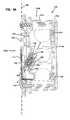
- FIG. 2is an exploded perspective view of the access box of FIG. 1A .
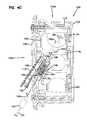
- FIG. 3is a perspective view of the access box of FIG. 1A having a cable mounting panel in an open position.
- FIGS. 4A-4Care side sectional views of the access box of FIG. 1A in various access positions.
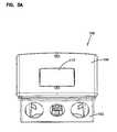
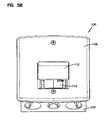
- FIGS. 5A-5Care bottom perspective views of the access box of FIG. 1A in various access positions.
- FIGS. 1A and 1Bdepict a telecommunications device configured as a covered cable access box 100 .
- the access box 100(and the components thereof) includes a front side 100 a and a top side 100 b .
- the access box 100includes a mounting box 102 which may be an electrical box typically used in the building construction industry for electrical power distribution.
- the mounting box 102may define a number of openings 104 on one or more sides, or on the rear of the mounting box 102 .
- the openings 104allow cable to pass into the mounting box 102 .
- a faceplate 106may be secured to the access box 100 via a number of screws 108 , press-fit connections, or other connection elements.
- the faceplate 106defines an opening 110 in which is located a pivoting cover panel 112 , the operation of which is described below.
- FIG. 1Bdepicts this cover panel 112 in an open position, where it is positioned at an angle relative to the faceplate 106 , such that the cover panel 112 is at an angle oblique to a vertical face of the faceplate 106 .
- FIG. 2depicts an exploded perspective view of the access box 100 .
- the mounting box 102is configured to receive a support box 114 .
- the support box 114defines a number of openings 116 to allow a cable to be inserted from an exterior of the support box 114 to an interior thereof.
- the access box 100utilizes both a mounting box 102 and a support box 114 , other embodiments that utilize only one or the other are contemplated.
- the mounting box 102includes a number of projections 118 that are configured to align with projections 120 on the support box 114 .
- Either or both of these projections 118 , 120may be configured to receive one or more screws 122 , press fit connectors, or other elements to secure the various components of the access box 100 relative to each other.
- One or more splice holders 124may be located within the interior of the support box 114 , and may be discrete from the support box 114 or manufactured integrally therewith.
- Cable/fiber management structurescan be provided within the support box 114 .
- one or more spooling structurescan be provided within the support box 114 for spooling excess cable/fiber in a looped configuration without violating minimum bend radius requirements of the fiber/cable.
- a connector mounting panel 126is secured to the support box 114 .
- the connector mounting panel 126is pivotably connected at a hinge 128 that may be located along a top, side, or bottom portion of the connector mounting panel 126 .
- the hinge 128allows pivoting movement of the connector mounting panel 126 around a hinge axis H (see FIG. 3 ).
- the connector mounting panel 126may be pivotably secured to the mounting box 102 .
- the connector mounting panel 126includes a latch 130 located opposite the hinge 128 that may hold the connector mounting panel 126 in a closed position, releasably secured to the support box 114 .
- the connector mounting panel 126prevents access to the interior of the support box 114 , discouraging tampering with the cables located therein.
- An opening 132may be used to receive a screw 134 to more robustly secure the connector mounting panel 126 to the support box 114 , so as to further deter tampering.
- press fit connections, or other securing elementsmay be used to secure the connector mounting panel 126 against pivoting.
- the connector mounting panel 126includes a mounting surface 136 for a cable connection device 138 , which in this case is a fiber optic adapter.
- a biasing element 140such as a spring, may be used to bias the cover panel 112 toward a closed position, as described in more detail below.
- An access panel 142is carried by and pivotably secured to the cover panel 112 , and may also be biased with a biasing element 144 .
- the access panel biasing element 144biases the access panel 142 into a first access panel position such that the access panel 142 is positioned substantially orthogonal to the cover panel 112 .
- Either or both of the biasing elements 140 , 144may include at least one of a coil spring, an elastomeric element, a leaf spring, and a torsion spring. In other embodiments, the biasing elements 140 , 144 may be incorporated into a single unitary part, such as a more complex leaf spring.
- FIG. 3depicts the access box 100 of FIG. 1A , notably the support box 114 and the connector mounting panel 126 pivotably mounted thereto in an open position. In the open position, access to the interior of the support box 114 is possible for service or other purposes. A number of elements depicted in FIG. 3 are already described above, accordingly, these elements are generally not described further.
- the interior of the support box 114may define a plurality of cable management structures 114 a , channels, elements, etc., which may be used to secure the cable inserted therein against movement or excessive bending, which may damage the cable.
- the hinge 128is integral with the connector mounting panel 126 and is secured directly to an outer portion of the support box 114 for pivotal movement about the hinge axis H.
- a springmay bias the connector mounting panel 126 into a closed position, where the latch 130 is in contact with the support box 114 .
- the connector mounting panel 126includes at least one angled surface 146 , and defines an opening 148 through which the cable connection device 138 may pass.
- the connection device 138can be secured in the opening 148 by a snap-fit connection.
- the angled surface 146is the same as the mounting surface 136 . The functionality of this angled surface 146 is described in further detail with reference to the following figures.
- the cover panel 112(not visible in FIG. 3 ) is connected to the connector mounting panel 126 at a pivot 150 . In alternative embodiments, the cover panel 126 may be pivotably connected to an interior surface of the faceplate 106
- FIG. 4A-4Cdepict side sectional views of the access box 100 with the cover panel 112 and access panel 142 in various positions.
- the front side 100 a and the top side 100 bare also depicted.
- FIG. 4Adepicts the cover panel 112 in a closed position and the access panel 142 in a first access panel position. In the closed position, the cover panel 112 is substantially parallel to the faceplate 106 . Additionally, in the first access panel position, the access panel 142 extends substantially orthogonally from the cover panel 112 .
- the cable connection device 138in this case a fiber optic adapter, includes an outer body 152 and an inner sleeve 154 .
- the inner sleeve 154includes an outer end 156 for connection to an exterior cable and an inner end 158 for connection to the cable inside the access box 100 .
- the outer end 156can receive a ferrule 160 a of a connector 160 terminated to an exterior cable 161 and the inner end 158 can receive a ferrule 162 a of a connector 162 terminated to an internal cable 163 routed within the access box 100 .
- any light directed out from the fiber optic connector 162will be directed at the cover plate 112 (generally parallel to or coaxial with an axis A oblique to the faceplate 106 , as defined by the cable connection device 138 ).
- the angle at which axis A is oblique to the faceplate 106may, in certain embodiments, be substantially parallel to the maximum angle that the cover plate 112 may be opened.
- the angled surface 146functions to angle the axis A forwardly and downwardly. This angling can assist in limiting bending of the cable 161 .
- the axis Acan be referred to as a connector insertion axis.
- the axis Ais also oriented at an oblique angle relative to a vertical reference plane RP that generally corresponds to a front side of the access box 100 .
- FIG. 4Bdepicts the access box 100 with the cover panel 112 in the open position.
- a portion of the cover panel 112 above the pivot 150may be pressed inward, thus pivoting the portion below the pivot 150 away from the faceplate 106 . This may occur when a person wishes to obtain access to the cable connection device 138 .
- the cover plate 106With the cover plate 106 in the open position, light from the cable connection device 138 (again, as defined by the axis A), is directed toward the access panel 142 , thus preventing light from exiting the access box 100 .
- the access panel 142in the second access panel position, is substantially parallel to the angled surface 146 , thus making the access panel 142 substantially orthogonal to any light emitted from the connector 138 . In other embodiments, however, the access panel 142 need only intersect the emitted light to prevent escape thereof from the interior of the access box 100 .
- the access panel 142In the first access position, the access panel 142 is generally orthogonal with respect to the cover plate 112 .
- the access panel 142pivotally connects to the cover plate 112 adjacent a lower end of the cover plate 112 .
- the cover plate 112when the cover plate 112 is in the open position, the cover plate 112 is generally parallel to the axis A (i.e., the light beam path) and does not intersect the axis A.
- the access panel 142may be moved from the first access panel position depicted in FIG. 4B to a second access panel position depicted in FIG. 4C .
- the access panel 142no longer intersects the emitted light defined by axis A and a cable 161 may be connected to the outer port 156 of the cable connection device 138 .
- the dual action movement requiredhelps prevent inadvertent emission of the light by a person potentially unfamiliar with the operation of fiber optic systems.
- FIG. 4Calso depicts an inner cable 163 , which is connected to the inner port 158 of the cable connection device 138 .
- FIGS. 5A-5Cdepict bottom perspective views of the access box 100 .
- the cover panel 112is in the closed position and the cable connection device is not visible (therefore, light will not be emitted from the access box 100 ).
- the cover panel 112has been moved to the open position.
- the position of the access panel 142 in the first access panel positionprevents light from being emitted from the access box 100 , and otherwise blocks access to the cable connection device 138 .
- FIG. 5Cdepicts the cable connection device 138 , as viewed from a bottom of the access box 100 .
- the access panel 142has been moved to the second access panel position, thus allowing emitted light to leave the access box 100 .
- the second access panel positionnow allows access to the outer interface 156 of the cable connection device 138 , and enables connection of a cable thereto.
- the access boxesmay be any size typically used for single or multi-gang switches or outlets, or custom sizes may be fabricated, depending on the particular application. Additionally, multiple cables or types of cables may be routed to the box, with multiple connectors located on the connector mounting panel. In certain embodiments, the mounting box and/or support box may be manufactured with punch outs on all sides of the box, such that cable may be inserted in any location.
- access boxes described hereinare typically installed behind wall panels, surface-mounted installations may also be utilized if, for example, an access box is installed in an unfinished room or other space.
- access boxes used primarily for fiber optic distribution systemsare described herein, they also may be utilized for any service where it may be desirable to hide the connector.
- the systemmay be used for coaxial cable, building electrical power, etc.
- the described access boxesnot only prevent light from being emitted from exposed fiber optic connectors, but also are aesthetically pleasing, and help reduce damage to the connector, unauthorized access thereto, or build-up of dust or debris on the connector.
- the access boxes described hereinhave applications beyond fiber optic systems. With sufficient water shedding surfaces and gaskets, the access boxes may also be made substantially weatherproof, making them useful in outdoor or other wet applications.
- the materials used for the boxes and components described hereinmay be the same as those typically used for electrical boxes used in the construction industry. These may include injection molded plastics and metals such as zinc and steel. Additionally, corrosion resistant metals such as stainless steel may be used if the system is to be used in environments where such resistance to corrosion is required or desired. These environments may include outdoor applications, marine environments, etc.
Landscapes
- Physics & Mathematics (AREA)
- General Physics & Mathematics (AREA)
- Optics & Photonics (AREA)
- Engineering & Computer Science (AREA)
- Civil Engineering (AREA)
- Structural Engineering (AREA)
- Light Guides In General And Applications Therefor (AREA)
- Connector Housings Or Holding Contact Members (AREA)
Abstract
Description
Claims (20)
Priority Applications (1)
| Application Number | Priority Date | Filing Date | Title |
|---|---|---|---|
| US13/859,283US9020321B2 (en) | 2012-04-10 | 2013-04-09 | Wall outlet having enclosed service connection |
Applications Claiming Priority (2)
| Application Number | Priority Date | Filing Date | Title |
|---|---|---|---|
| US201261622276P | 2012-04-10 | 2012-04-10 | |
| US13/859,283US9020321B2 (en) | 2012-04-10 | 2013-04-09 | Wall outlet having enclosed service connection |
Publications (2)
| Publication Number | Publication Date |
|---|---|
| US20130287358A1 US20130287358A1 (en) | 2013-10-31 |
| US9020321B2true US9020321B2 (en) | 2015-04-28 |
Family
ID=49477357
Family Applications (1)
| Application Number | Title | Priority Date | Filing Date |
|---|---|---|---|
| US13/859,283Expired - Fee RelatedUS9020321B2 (en) | 2012-04-10 | 2013-04-09 | Wall outlet having enclosed service connection |
Country Status (1)
| Country | Link |
|---|---|
| US (1) | US9020321B2 (en) |
Cited By (1)
| Publication number | Priority date | Publication date | Assignee | Title |
|---|---|---|---|---|
| EP4105699A1 (en)* | 2021-06-17 | 2022-12-21 | Kaiser GmbH & Co. KG | Socket insert for an installation socket |
Families Citing this family (8)
| Publication number | Priority date | Publication date | Assignee | Title |
|---|---|---|---|---|
| US20150071596A1 (en)* | 2013-09-10 | 2015-03-12 | Centurylink Intellectual Property Llc | Fiber distribution hub in a fttu mdu |
| WO2015067645A1 (en)* | 2013-11-06 | 2015-05-14 | Adc Czech Republic, S.R.O. | Fiber termination point with overlength storage |
| US10509187B2 (en)* | 2014-09-23 | 2019-12-17 | Ppc Broadband, Inc. | Universal multi-purpose compartmentalized telecommunications box |
| WO2016049242A1 (en)* | 2014-09-23 | 2016-03-31 | Ppc Broadband, Inc. | Universal multi-purpose compartmentalized telecommunications box |
| US10162143B1 (en)* | 2017-09-21 | 2018-12-25 | Ofs Fitel, Llc | Behind-the-wall fiber spool module |
| CA3142274A1 (en) | 2019-06-04 | 2020-12-10 | Ppc Broadband Fiber Ltd. | Enclosure box for fiber optic cable |
| CN113450487B (en)* | 2021-05-21 | 2022-03-25 | 浙江宏海智能科技有限公司 | Intelligent building access control system |
| EP4296740A1 (en)* | 2022-06-23 | 2023-12-27 | Corning Research & Development Corporation | Modular fiber optic outlet |
Citations (11)
| Publication number | Priority date | Publication date | Assignee | Title |
|---|---|---|---|---|
| US4874904A (en) | 1988-04-14 | 1989-10-17 | Brintec Corporation | Fiber optic faceplate assembly |
| US5351176A (en)* | 1992-12-31 | 1994-09-27 | North Atlantic Industries, Inc. | Panel for a computer including a hinged door with integral display |
| US6315598B1 (en) | 2000-02-01 | 2001-11-13 | Adc Telecommunications, Inc. | Outlet box with cable management spool |
| US6363200B1 (en) | 1998-07-27 | 2002-03-26 | Adc Telecommunications, Inc. | Outside plant fiber distribution apparatus and method |
| US20020043033A1 (en)* | 2000-10-13 | 2002-04-18 | Szyjkowski Jerzy Marek | Access door mounted on pivoting frame |
| US6379166B1 (en) | 2000-06-26 | 2002-04-30 | Randl Industries, Inc. | Fiber optic cable outlet box |
| US7292763B2 (en) | 2004-03-08 | 2007-11-06 | Adc Telecommunications, Inc. | Fiber access terminal |
| US7361052B2 (en) | 2000-02-01 | 2008-04-22 | Adc Telecommunications, Inc. | Multimedia outlet box |
| US7751675B2 (en) | 2007-12-11 | 2010-07-06 | Adc Telecommunications, Inc. | Wall box adapted to be mounted at a mid-span access location of a telecommunications cable |
| US20100209065A1 (en)* | 2009-02-18 | 2010-08-19 | Gil Ruiz | Optical fiber management shelf including door with push-push fastener |
| US20110155412A1 (en)* | 2009-12-31 | 2011-06-30 | Christopher Clifton | Electrical interface assembly |
- 2013
- 2013-04-09USUS13/859,283patent/US9020321B2/ennot_activeExpired - Fee Related
Patent Citations (11)
| Publication number | Priority date | Publication date | Assignee | Title |
|---|---|---|---|---|
| US4874904A (en) | 1988-04-14 | 1989-10-17 | Brintec Corporation | Fiber optic faceplate assembly |
| US5351176A (en)* | 1992-12-31 | 1994-09-27 | North Atlantic Industries, Inc. | Panel for a computer including a hinged door with integral display |
| US6363200B1 (en) | 1998-07-27 | 2002-03-26 | Adc Telecommunications, Inc. | Outside plant fiber distribution apparatus and method |
| US6315598B1 (en) | 2000-02-01 | 2001-11-13 | Adc Telecommunications, Inc. | Outlet box with cable management spool |
| US7361052B2 (en) | 2000-02-01 | 2008-04-22 | Adc Telecommunications, Inc. | Multimedia outlet box |
| US6379166B1 (en) | 2000-06-26 | 2002-04-30 | Randl Industries, Inc. | Fiber optic cable outlet box |
| US20020043033A1 (en)* | 2000-10-13 | 2002-04-18 | Szyjkowski Jerzy Marek | Access door mounted on pivoting frame |
| US7292763B2 (en) | 2004-03-08 | 2007-11-06 | Adc Telecommunications, Inc. | Fiber access terminal |
| US7751675B2 (en) | 2007-12-11 | 2010-07-06 | Adc Telecommunications, Inc. | Wall box adapted to be mounted at a mid-span access location of a telecommunications cable |
| US20100209065A1 (en)* | 2009-02-18 | 2010-08-19 | Gil Ruiz | Optical fiber management shelf including door with push-push fastener |
| US20110155412A1 (en)* | 2009-12-31 | 2011-06-30 | Christopher Clifton | Electrical interface assembly |
Cited By (1)
| Publication number | Priority date | Publication date | Assignee | Title |
|---|---|---|---|---|
| EP4105699A1 (en)* | 2021-06-17 | 2022-12-21 | Kaiser GmbH & Co. KG | Socket insert for an installation socket |
Also Published As
| Publication number | Publication date |
|---|---|
| US20130287358A1 (en) | 2013-10-31 |
Similar Documents
| Publication | Publication Date | Title |
|---|---|---|
| US9020321B2 (en) | Wall outlet having enclosed service connection | |
| US6379166B1 (en) | Fiber optic cable outlet box | |
| US6410850B1 (en) | Cable enclosure assembly | |
| US7010210B2 (en) | Entry and internal fiber clips for a fiber management system | |
| US7343078B2 (en) | Patch panels with communications connectors that are rotatable about a vertical axis | |
| US5645449A (en) | Low profile mixed media information outlet | |
| US8295036B2 (en) | Expandable power and data center with latching mechanism | |
| US5969294A (en) | Fiber optic connector cabinet with rotatably mounted adapter panels | |
| US9360648B2 (en) | Systems and methods for the management of fiber optic cables | |
| US7608780B2 (en) | Back plate for network connection box | |
| TW200903921A (en) | Communication socket | |
| US8805153B2 (en) | Systems and methods for the management of fiber optic cables | |
| EP2105770A1 (en) | Outlet device | |
| WO2006138285A2 (en) | One touch pivoting expandable power and data center | |
| US20180123331A1 (en) | Support frame for structured cabling system | |
| US5838858A (en) | Fiber optic connection unit | |
| US20090221179A1 (en) | Tamper resistant faceplate system | |
| KR102641857B1 (en) | Optical connector holder and optical connector assembly including it | |
| US20020137392A1 (en) | Patch cord cable manager | |
| JP3351604B2 (en) | Optical information input / output device | |
| US20030054680A1 (en) | Assemly for an outlet | |
| US6522824B2 (en) | Corner wall-mount fiber optic connector housing | |
| KR100780146B1 (en) | Embedded outlet socket for optical fiber cable | |
| US20230280540A1 (en) | Cable enclosure assembly having receiving area configured to alternatively receive cable retainer and cable adapter to allow plurality of configurations | |
| WO2001061815A1 (en) | Assembly for an outlet |
Legal Events
| Date | Code | Title | Description |
|---|---|---|---|
| AS | Assignment | Owner name:TYCO ELECTRONICS CORPORATION, PENNSYLVANIA Free format text:ASSIGNMENT OF ASSIGNORS INTEREST;ASSIGNORS:ALSTON, ERIC E.;MULLANEY, JULIAN S.;CARRICO, WILLIAM ALAN;AND OTHERS;REEL/FRAME:034519/0242 Effective date:20141031 | |
| STCF | Information on status: patent grant | Free format text:PATENTED CASE | |
| AS | Assignment | Owner name:ADC TELECOMMUNICATIONS, INC., PENNSYLVANIA Free format text:ASSIGNMENT OF ASSIGNORS INTEREST;ASSIGNOR:TYCO ELECTRONICS CORPORATION;REEL/FRAME:036907/0571 Effective date:20150824 | |
| AS | Assignment | Owner name:TYCO ELECTRONICS SERVICES GMBH, SWITZERLAND Free format text:ASSIGNMENT OF ASSIGNORS INTEREST;ASSIGNORS:ADC TELECOMMUNICATIONS, INC.;TE CONNECTIVITY SOLUTIONS GMBH;REEL/FRAME:036908/0443 Effective date:20150825 | |
| AS | Assignment | Owner name:COMMSCOPE EMEA LIMITED, IRELAND Free format text:ASSIGNMENT OF ASSIGNORS INTEREST;ASSIGNOR:TYCO ELECTRONICS SERVICES GMBH;REEL/FRAME:036956/0001 Effective date:20150828 | |
| AS | Assignment | Owner name:COMMSCOPE TECHNOLOGIES LLC, NORTH CAROLINA Free format text:ASSIGNMENT OF ASSIGNORS INTEREST;ASSIGNOR:COMMSCOPE EMEA LIMITED;REEL/FRAME:037012/0001 Effective date:20150828 | |
| AS | Assignment | Owner name:JPMORGAN CHASE BANK, N.A., AS COLLATERAL AGENT, ILLINOIS Free format text:PATENT SECURITY AGREEMENT (TERM);ASSIGNOR:COMMSCOPE TECHNOLOGIES LLC;REEL/FRAME:037513/0709 Effective date:20151220 Owner name:JPMORGAN CHASE BANK, N.A., AS COLLATERAL AGENT, ILLINOIS Free format text:PATENT SECURITY AGREEMENT (ABL);ASSIGNOR:COMMSCOPE TECHNOLOGIES LLC;REEL/FRAME:037514/0196 Effective date:20151220 Owner name:JPMORGAN CHASE BANK, N.A., AS COLLATERAL AGENT, IL Free format text:PATENT SECURITY AGREEMENT (TERM);ASSIGNOR:COMMSCOPE TECHNOLOGIES LLC;REEL/FRAME:037513/0709 Effective date:20151220 Owner name:JPMORGAN CHASE BANK, N.A., AS COLLATERAL AGENT, IL Free format text:PATENT SECURITY AGREEMENT (ABL);ASSIGNOR:COMMSCOPE TECHNOLOGIES LLC;REEL/FRAME:037514/0196 Effective date:20151220 | |
| FEPP | Fee payment procedure | Free format text:MAINTENANCE FEE REMINDER MAILED (ORIGINAL EVENT CODE: REM.); ENTITY STATUS OF PATENT OWNER: LARGE ENTITY | |
| AS | Assignment | Owner name:COMMSCOPE TECHNOLOGIES LLC, NORTH CAROLINA Free format text:RELEASE BY SECURED PARTY;ASSIGNOR:JPMORGAN CHASE BANK, N.A.;REEL/FRAME:048840/0001 Effective date:20190404 Owner name:ALLEN TELECOM LLC, ILLINOIS Free format text:RELEASE BY SECURED PARTY;ASSIGNOR:JPMORGAN CHASE BANK, N.A.;REEL/FRAME:048840/0001 Effective date:20190404 Owner name:COMMSCOPE, INC. OF NORTH CAROLINA, NORTH CAROLINA Free format text:RELEASE BY SECURED PARTY;ASSIGNOR:JPMORGAN CHASE BANK, N.A.;REEL/FRAME:048840/0001 Effective date:20190404 Owner name:REDWOOD SYSTEMS, INC., NORTH CAROLINA Free format text:RELEASE BY SECURED PARTY;ASSIGNOR:JPMORGAN CHASE BANK, N.A.;REEL/FRAME:048840/0001 Effective date:20190404 Owner name:ANDREW LLC, NORTH CAROLINA Free format text:RELEASE BY SECURED PARTY;ASSIGNOR:JPMORGAN CHASE BANK, N.A.;REEL/FRAME:048840/0001 Effective date:20190404 Owner name:COMMSCOPE, INC. OF NORTH CAROLINA, NORTH CAROLINA Free format text:RELEASE BY SECURED PARTY;ASSIGNOR:JPMORGAN CHASE BANK, N.A.;REEL/FRAME:049260/0001 Effective date:20190404 Owner name:ANDREW LLC, NORTH CAROLINA Free format text:RELEASE BY SECURED PARTY;ASSIGNOR:JPMORGAN CHASE BANK, N.A.;REEL/FRAME:049260/0001 Effective date:20190404 Owner name:REDWOOD SYSTEMS, INC., NORTH CAROLINA Free format text:RELEASE BY SECURED PARTY;ASSIGNOR:JPMORGAN CHASE BANK, N.A.;REEL/FRAME:049260/0001 Effective date:20190404 Owner name:ALLEN TELECOM LLC, ILLINOIS Free format text:RELEASE BY SECURED PARTY;ASSIGNOR:JPMORGAN CHASE BANK, N.A.;REEL/FRAME:049260/0001 Effective date:20190404 Owner name:COMMSCOPE TECHNOLOGIES LLC, NORTH CAROLINA Free format text:RELEASE BY SECURED PARTY;ASSIGNOR:JPMORGAN CHASE BANK, N.A.;REEL/FRAME:049260/0001 Effective date:20190404 | |
| LAPS | Lapse for failure to pay maintenance fees | Free format text:PATENT EXPIRED FOR FAILURE TO PAY MAINTENANCE FEES (ORIGINAL EVENT CODE: EXP.); ENTITY STATUS OF PATENT OWNER: LARGE ENTITY | |
| STCH | Information on status: patent discontinuation | Free format text:PATENT EXPIRED DUE TO NONPAYMENT OF MAINTENANCE FEES UNDER 37 CFR 1.362 | |
| FP | Lapsed due to failure to pay maintenance fee | Effective date:20190428 | |
| AS | Assignment | Owner name:JPMORGAN CHASE BANK, N.A., NEW YORK Free format text:ABL SECURITY AGREEMENT;ASSIGNORS:COMMSCOPE, INC. OF NORTH CAROLINA;COMMSCOPE TECHNOLOGIES LLC;ARRIS ENTERPRISES LLC;AND OTHERS;REEL/FRAME:049892/0396 Effective date:20190404 Owner name:JPMORGAN CHASE BANK, N.A., NEW YORK Free format text:TERM LOAN SECURITY AGREEMENT;ASSIGNORS:COMMSCOPE, INC. OF NORTH CAROLINA;COMMSCOPE TECHNOLOGIES LLC;ARRIS ENTERPRISES LLC;AND OTHERS;REEL/FRAME:049905/0504 Effective date:20190404 Owner name:WILMINGTON TRUST, NATIONAL ASSOCIATION, AS COLLATE Free format text:PATENT SECURITY AGREEMENT;ASSIGNOR:COMMSCOPE TECHNOLOGIES LLC;REEL/FRAME:049892/0051 Effective date:20190404 Owner name:WILMINGTON TRUST, NATIONAL ASSOCIATION, AS COLLATERAL AGENT, CONNECTICUT Free format text:PATENT SECURITY AGREEMENT;ASSIGNOR:COMMSCOPE TECHNOLOGIES LLC;REEL/FRAME:049892/0051 Effective date:20190404 | |
| AS | Assignment | Owner name:RUCKUS WIRELESS, LLC (F/K/A RUCKUS WIRELESS, INC.), NORTH CAROLINA Free format text:RELEASE OF SECURITY INTEREST AT REEL/FRAME 049905/0504;ASSIGNOR:JPMORGAN CHASE BANK, N.A., AS COLLATERAL AGENT;REEL/FRAME:071477/0255 Effective date:20241217 Owner name:COMMSCOPE TECHNOLOGIES LLC, NORTH CAROLINA Free format text:RELEASE OF SECURITY INTEREST AT REEL/FRAME 049905/0504;ASSIGNOR:JPMORGAN CHASE BANK, N.A., AS COLLATERAL AGENT;REEL/FRAME:071477/0255 Effective date:20241217 Owner name:COMMSCOPE, INC. OF NORTH CAROLINA, NORTH CAROLINA Free format text:RELEASE OF SECURITY INTEREST AT REEL/FRAME 049905/0504;ASSIGNOR:JPMORGAN CHASE BANK, N.A., AS COLLATERAL AGENT;REEL/FRAME:071477/0255 Effective date:20241217 Owner name:ARRIS SOLUTIONS, INC., NORTH CAROLINA Free format text:RELEASE OF SECURITY INTEREST AT REEL/FRAME 049905/0504;ASSIGNOR:JPMORGAN CHASE BANK, N.A., AS COLLATERAL AGENT;REEL/FRAME:071477/0255 Effective date:20241217 Owner name:ARRIS TECHNOLOGY, INC., NORTH CAROLINA Free format text:RELEASE OF SECURITY INTEREST AT REEL/FRAME 049905/0504;ASSIGNOR:JPMORGAN CHASE BANK, N.A., AS COLLATERAL AGENT;REEL/FRAME:071477/0255 Effective date:20241217 Owner name:ARRIS ENTERPRISES LLC (F/K/A ARRIS ENTERPRISES, INC.), NORTH CAROLINA Free format text:RELEASE OF SECURITY INTEREST AT REEL/FRAME 049905/0504;ASSIGNOR:JPMORGAN CHASE BANK, N.A., AS COLLATERAL AGENT;REEL/FRAME:071477/0255 Effective date:20241217 |