US9019718B2 - Modular electronic building systems with magnetic interconnections and methods of using the same - Google Patents
Modular electronic building systems with magnetic interconnections and methods of using the sameDownload PDFInfo
- Publication number
- US9019718B2 US9019718B2US13/593,891US201213593891AUS9019718B2US 9019718 B2US9019718 B2US 9019718B2US 201213593891 AUS201213593891 AUS 201213593891AUS 9019718 B2US9019718 B2US 9019718B2
- Authority
- US
- United States
- Prior art keywords
- electrical
- module
- modules
- housing
- connector
- Prior art date
- Legal status (The legal status is an assumption and is not a legal conclusion. Google has not performed a legal analysis and makes no representation as to the accuracy of the status listed.)
- Active, expires
Links
Images


Classifications
- H—ELECTRICITY
- H01—ELECTRIC ELEMENTS
- H01R—ELECTRICALLY-CONDUCTIVE CONNECTIONS; STRUCTURAL ASSOCIATIONS OF A PLURALITY OF MUTUALLY-INSULATED ELECTRICAL CONNECTING ELEMENTS; COUPLING DEVICES; CURRENT COLLECTORS
- H01R13/00—Details of coupling devices of the kinds covered by groups H01R12/70 or H01R24/00 - H01R33/00
- H01R13/62—Means for facilitating engagement or disengagement of coupling parts or for holding them in engagement
- H01R13/6205—Two-part coupling devices held in engagement by a magnet
- H—ELECTRICITY
- H01—ELECTRIC ELEMENTS
- H01R—ELECTRICALLY-CONDUCTIVE CONNECTIONS; STRUCTURAL ASSOCIATIONS OF A PLURALITY OF MUTUALLY-INSULATED ELECTRICAL CONNECTING ELEMENTS; COUPLING DEVICES; CURRENT COLLECTORS
- H01R11/00—Individual connecting elements providing two or more spaced connecting locations for conductive members which are, or may be, thereby interconnected, e.g. end pieces for wires or cables supported by the wire or cable and having means for facilitating electrical connection to some other wire, terminal, or conductive member, blocks of binding posts
- H01R11/11—End pieces or tapping pieces for wires, supported by the wire and for facilitating electrical connection to some other wire, terminal or conductive member
- H01R11/30—End pieces held in contact by a magnet
Definitions
- the present inventionrelates to the field of electronics and, more particularly, to electronic building blocks and toy building sets.
- an electronic educational toy or building systemthat teaches the logic of programming and circuit building without requiring expertise in either.
- the modular block building systemconsists of pre-assembled printed circuit boards (PCB) interconnected by small magnets. Each block performs one or more discrete functions (e.g., an LED, a pushbutton, a light sensor with a threshold, etc.), and the blocks can be combined to create larger circuits. Some blocks respond to external events such as mechanical forces, touch, proximity, radio frequency signals, environmental conditions, etc. Other blocks are pre-programmed such as synthesizers, oscillators, etc. Still other blocks simply pass current like wire blocks. Yet other blocks provide current such as power blocks/modules.
- PCBprinted circuit boards
- the systemincludes modules having many different manners of interaction between the modules.
- the interaction between modules, not the modules themselves,may form the building blocks of the creative platform.
- the electronic componentmay be at the center of the manipulation: resistors, capacitors, batteries, etc.
- resistors, capacitors, batteries, etc.By manipulating the modules in those kits, children learn how electricity flows, how to design a circuit, or how to identify components.
- This knowledgeis application specific and features only a single circuit. It has little or no bearing on how the touch sensitive wheel of an iPodTM works, for example, or how a nightlight works, or how a cell phone vibrates, or how a phone can detect rotation and automatically rotate images on the screen in response to that rotation, or how to make one's own objects that have that interactivity.
- the modulesmay be divided into categories corresponding to their function. Examples of categories include, but are not limited to: power modules, input modules, output modules, wire modules, etc. Power modules for instance take current from a battery, a wall wart, or other power source, and convert it into current feeding the other components of the system. In any working configuration of modules, there may be at least one power module.
- Input modulesinclude, but are not limited to: buttons, switches, sensors, logic blocks, etc.
- Output modulesinclude, but are not limited to: LEDs, displays, sound modules, etc. Wire modules do not perform a particular function, but act as wire extensions, configuration changers, and in some cases logic and state modules.
- standalone blocksare provided that may enable users, with little or no electronics or programming experience, to construct basic and complex sensor and interaction-based analog and digital circuits.
- All modulesmay include a standard interface and communicate automatically when connected. Each module includes three electrical lines and such lines are interconnected between and throughout all modules. These lines include Power, Signal and Ground. At the power modules, Power and Signal lines are at 5 Volts, the system is low power, and the Power and Ground lines are shared among all the modules. In other exemplary embodiments, the power may be something other than 5 Volts such as, for example, 3V, 9V, 12V, 15V, alternating current (AC), etc. Input modules take the incoming control Signal line, and manipulate it according to the module's function, and output the modified Signal voltage.
- the sensor moduletakes 5 Volts into the Signal line, and outputs a voltage between 0 and 5 Volts depending on the amount of pressure applied to the sensor.
- Output modulesrespond to the Signal line by “visualizing” the voltage in light, sound, display or other forms.
- All modulesare pre-assembled, pre-engineered, and contain the logic and circuitry required to make the component readily usable.
- an LED modulecontains a resistor corresponding to its current rating, an Operation Amplifier (OpAmp) as a buffer from the remainder of the circuit, and a coin cell battery module incorporates a discharge protection circuit.
- the systemrequires no prior knowledge of electronics and does not require any hardware or software platform.
- the systemmay include a hardware and/or software platform.
- the modulesdo not need to be programmed and do not require a central circuit controlling them, the system is standalone and does not need a computer or hub.
- the systemmay be connected to a device such as a computer, hub, memory storage, or personal electronic mobile device such as a cellular phone, smart phone, etc., in order to create additional functionality or to retrieve information or power from the device.
- a devicesuch as a computer, hub, memory storage, or personal electronic mobile device such as a cellular phone, smart phone, etc.
- the modulesare designed to couple together and cascade one after the next.
- the modulesinclude magnetic connectors that ensure electrical connectivity and may be developed and mounted on the PCB.
- the magnetic connectorsmay be in male form and female form, and in some examples may correspond to north and south faces of magnets.
- each blockmay have two magnetic connectors mounted on it, one with the north face of the magnet(s) facing out and the other with the south face of the magnet(s) facing out.
- the south facing side of the magnetic connector of one moduleconnects to the north facing side of the magnetic connector on the next module. This ensures proper connection and appropriate polarity.
- the repelling polaritiesinhibit the magnets from connecting in an inappropriate manner to facilitate connecting of the modules in the correct manner.
- the magnetic connectorincludes two magnets and three conductors embedded in an injection molded plastic body.
- the two magnetsact as polarizing and locking elements, whereas the conductors carry the signal from one circuit board to the next through the mating of the male and female connectors.
- the three conductorsare spring probes.
- the conductorsmay either be spring probes or small metal plates. Either way, the spring probes or the metal plates come into contact with the spring probes of the male connector and transfer the electrical signals into the circuit board.
- the magnetic connectoralso features an interlocking system as part of the plastic casing in the form of male and female complementary components.
- a male protrusionis included on one block and a female indentation is included on a second block.
- the protrusion and indentationcooperate to inhibit the blocks from sliding with respect to each other.
- a male protrusion and a female indentationare included on each block and the male protrusions and the female indentations on interfacing blocks cooperate to inhibit the blocks from sliding with respect to each other.
- the magnetic connectoralso features an interlocking system as part of the plastic casing in order to inhibit the modules from sliding side-to-side with respect to each other, and to ensure that the modules are assembled in the correct orientation (i.e., to inhibit an upside-down connection).
- the connectorscan include a protrusion on the male or female side that corresponds to an indentation on the corresponding female or male side. Once the modules are connected, the protrusion enters the indentation and the modules are sufficiently locked together such that side-to-side movement is inhibited.
- the connectorscan include a tabbed feature to inhibit side-to-side movement. For example, as shown in FIG.
- the portion of the connector nearest the circuit boardincludes both a rounded tab that protrudes laterally from the connector and a rounded indentation adjacent to the tab.
- a corresponding connectorwill include a rounded tab and indent in a configuration such that when the two connectors are adjoined, the rounded tab of the first connector inserts into the rounded protrusion of the second connector, and the rounded tab of the second connector inserts into the rounded protrusion of the first connector, thereby locking the two connectors together such that side-to-side movement is prevented.
- the connectorscan include one or more protrusions. For example, as shown in FIG.
- the portion of the connector furthest from the circuit board(the “top”) includes a series of horizontal protrusions.
- the horizontal protrusions on the two moduleswill properly align.
- the horizontal protrusions of the second connectorwould hit the rounded tab of the first connector and prevent the two connectors from properly adjoining.
- connectorsIn addition to the previously described exemplary connectors, many modifications to the connectors are possible, including, but not limited to, the casing, the type of conductors used, the number of conductors, as well as whether or not the magnets are acting as conductors, the number of magnets, the shape of the magnets, the polarity of the magnets, the manner in which the connectors couple to the circuit board of the block, etc.
- the number of available modulesneeds to be plenty. In general, only having a few nuts and bolts in the prototyping process is not very helpful, and alternatively can even be prohibitive.
- the present inventionallows for the addition of new modules according to the interconnection and voltage standards. For example, starting from a set of a hundred modules, we can imagine and design hundreds or thousands of additional modules that fit and cooperate with the present system to extend the system's functionality. For example, we can potentially build modules such as galvanic skin sensors, arsenic detectors, microcontroller modules, etc., as well as adapter boards to other electronic block building systems and interfaces.
- At least one exemplary embodimenthas been designed to allow for complex behaviors programmed through physical interaction.
- the setfeatures logic and state modules that introduce the concept of programming to novices. Examples of such modules are the AND, OR and NOT blocks, as well as the Threshold block. These enable the user to program certain behaviors of his/her designed system without needing to learn a programming language, to write code on a computer, or to program a microcontroller circuit. Programming here is done through using logic modules to create decision trees. Also, modules feature controls such as switches, knobs and buttons that enable selection of modes of behavior. Just like a blender can have three buttons, each button corresponding to a particular speed of its motor, some modules in the present invention allow for the selection of a mode or adjustment of their behavior.
- a proximity sensor blockcan contain a mode switch and a potentiometer.
- the threshold levelcan be set, determining the input voltage level beyond which the module should output a high.
- the modulecan go from normally-high to normally-low, in essence inverting its response to the desired threshold.
- All blocksmay be designed with space constraints in mind and may be kept at the minimum size possible in order to make the blocks easily integreable with other materials such as, for example, cardboard, plastic, pipe cleaners, etc.
- the blocksare user friendly in their look as well as their size, and make playing and prototyping with them attractive to children and adults alike regardless of the goal.
- the modulesmay be offered as individual blocks or as sets. These can range from standard block components to specialized sets such as sensor sets, mechanical sets, biological sets, sound sets, etc. Also, users can design and build their own modules or sets to extend the library.
- an electrical connectorin some aspects, includes a housing defining a side surface, an electrical conductor supported by the housing and including an engagement portion proximate the side surface of the housing, wherein the engagement portion is adapted to engage another electrical conductor of another electrical connector, a magnet supported by the housing proximate the side surface of the housing, a projection extending from the side surface of the housing, and a receptacle defined in the side surface of the housing.
- an electrical modulein other aspects, includes a circuit board and an electrical connector.
- the electrical connectorincludes a housing defining a side surface, an electrical conductor supported by the housing and including a coupling portion and an engagement portion, wherein the coupling portion is adapted to engage and electrically communicate with the circuit board, and wherein the engagement portion is proximate the side surface of the housing, a magnet supported by the housing proximate the side surface of the housing, a projection extending from the side surface of the housing, and a receptacle defined in the side surface of the housing.
- a systemin further aspects, includes a plurality of electrical modules selectively couplable together to transmit electrical current from one electrical module to another electrical module, each module has at least one functionality associated therewith and includes an electrical connector adapted to couple to an electrical connector of another one of the electrical modules, wherein, with the electrical connectors coupled together, a functionality of at least one of the plurality of electrical modules is dependent upon at least another one of the plurality of electrical modules.
- a systemin still other aspects, includes a plurality of electrical modules adapted to be selectively coupled to one another, wherein the plurality of electrical modules include at least a first electrical module and a second electrical module, the first electrical module including a first circuit board, and a first electrical connector including a first housing, a first electrical conductor supported by the first housing and including a first coupling portion and a first engagement portion, wherein the first coupling portion is adapted to engage and electrically communicate with the first circuit board, a first magnet supported by the first housing, a first projection extending from the first housing, and a first receptacle defined in the first housing.
- the second electrical moduleincludes a second circuit board, and a second electrical connector including a second housing, a second electrical conductor supported by the second housing and including a second coupling portion and a second engagement portion, wherein the second coupling portion is adapted to engage and electrically communicate with the second circuit board, a second magnet supported by the second housing, a second projection extending from the second housing, and a second receptacle defined in the second housing, wherein, with the first electrical module coupled to the second electrical module, the first magnet is magnetically coupled to the second magnet, the first engagement portion engages the second engagement portion, the first projection is at least partially positioned within the second receptacle, and the second projection is at least partially positioned within the first receptacle.
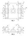
- FIG. 1is a top view of an exemplary module of the system
- FIG. 2is a side view of the module shown in FIG. 1 ;
- FIG. 3is a top view of a set of three modules before connecting the three modules
- FIG. 4is a top view of the three modules shown in FIG. 3 after connection to illustrate how the modules connect together using magnetic connectors of the modules;
- FIG. 5is a perspective view of an exemplary embodiment of a magnetic connector of a module
- FIG. 6is a top view of the magnetic connector shown in FIG. 5 ;
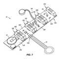
- FIG. 7is an exemplary configuration of four modules
- FIG. 8is a top view of an exemplary module of the system featuring controls
- FIG. 9is a perspective view of an exemplary set of three modules of the system including one module illustrating physical programming through controls;
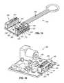
- FIG. 10is a perspective view of an exemplary packaged kit including a plurality of exemplary modules and an exemplary mounting board for mounting modules;
- FIG. 11is a perspective view of an exemplary wire module of the system.
- FIG. 12is a top perspective view of an exemplary output module of the system.
- FIG. 13is a top perspective view of another exemplary output module of the system.
- FIG. 14is a top perspective view of an exemplary input module of the system.
- FIG. 15is a top perspective view of another exemplary input module of the system.
- FIG. 16is a top perspective view of an exemplary power input module of the system.
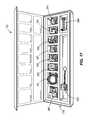
- FIG. 17is a top perspective view of an exemplary multi-module kit of the system.
- FIG. 18is a top perspective view of other exemplary modules and another exemplary mounting board of the exemplary system, each module including at least one of another exemplary connector for coupling together modules;
- FIG. 19is a bottom perspective view of two coupled together modules shown in FIG. 18 ;
- FIG. 20is a top exploded view of one of the modules shown in FIG. 18 ;
- FIG. 21is a top exploded view of one of the connectors shown in FIG. 18 ;
- FIG. 22is a bottom perspective view of two exemplary modules coupled together and an exemplary support member coupled to two of the connectors;
- FIG. 23is a top perspective view of the support member shown in FIG. 22 ;
- FIG. 24is a top perspective view of an exemplary mounting board coupled to an exemplary configuration of toy building blocks.
- FIG. 25is a bottom perspective view of the mounting board and exemplary toy building blocks shown in FIG. 24 .
- An exemplary electronic building system 30is provided.
- the electronic building system 30is not only meant for use with pre-designed components and modules 34 , but can also allow users to combine those modules 34 with other traditional prototyping and playing items in a design studio or home.
- Such materialsmay include, for example, paper, cardboard, wood, glue, pipe cleaners, foam, etc., thereby encouraging individuals to treat electronics like a material in the creative process.
- the system 30may include at least four different types of modules 34 : power; input; output; and wire; although more types of modules 34 are possible.
- Power modules 34provide electricity to the system 30 .
- Input modules 34interpret data or their surroundings and provide that input to the system 30 .
- Output modules 34make visual, physical, or audible changes to their surroundings based on input(s) to the system 30 .
- Wire modules 34route power and communication between the modules 34 in the system 30 .
- the power signalis transferred from the first module 34 to the second module 34 .
- the second module 34is powered entirely by the first module 34 .
- the currentmay be affected by the action of the button module 34 or sensor module 34 . For example, current may not pass (or, alternatively, may continuously pass) from the first module 34 to the second module 34 unless the button on the button module 34 is depressed or the sensor on the sensor module 34 is activated. Similarly, if a sensor module 34 is only partially activated, then only partial current is transferred from the first module 34 to the second module 34 .
- modules 34are possible in each category, including but not limited to the following: (i) power modules: wall power modules, battery power modules, solar power modules, discharge protection circuits; (ii) input modules: pulse modules, pressure sensor modules, proximity modules, input recording modules, potentiometer modules, button modules, temperature modules, accelerometer modules, memory modules, timer modules; (iii) output modules: motion modules, vibration motor modules, fan modules, RGB LED modules, LED modules, bar graph modules, speaker modules; and (iv) wire modules: wire modules of various lengths, extender modules, splitter modules, and electroluminescent wire modules. Any known type of circuit or electronic component or combination of components may be used to create a module 34 and thus form a portion of a system 30 built using such components.
- the modular system 30 described hereinis reusable, scalable from small and simple circuits to large and complex circuits, and are sophisticated enough to allow for complex programming of behavior through manipulating tangible objects (using logic and state modules 34 ). Additionally, just as programmers use software modules and libraries to create bigger and more complex software programs, the modules 34 are transformed into a library of electronic components that can be used to create bigger and more complex components or systems. Indeed, a user can expand the module library almost indefinitely, adding any new component that they wish to use to their module repository.
- userscan even create their own modules 34 and add them to the rest of the library.
- usersmay be provided with components of a module 34 —such as male magnetic connectors 38 A and female magnetic connectors 38 B that are able to snap onto or otherwise couple to a small circuit board, sensor, or other electronic component such that the connectors 38 A/ 38 B transmit current from one module 34 to another—that they can use to create their own inter-connectable modules 34 built from circuit board, sensors, or output mechanisms that they have built or gathered from another source.
- a system 30comprising several modules 34 may be commercialized as a single kit or set.
- the kitmay include one or more different modules 34 (power, input, output, and/or wire), may comprise one or more different types of each module 34 , a container in which to store the modules 34 , a mounting board or substrate upon which to place or couple modules, may include learning materials, accessories, instructions, or a variety of other components.
- a kitmay comprise a handful of modules 34 that may be connected in an almost unlimited number of combinations to perform numerous different input and output functions (see FIGS. 10 and 17 ).
- the kitmay also comprise a limited number of modules 34 that are intended to be assembled in a limited number of combinations, including a single combination, to perform a limited number of functions.
- the kitcan comprise as many as tens or hundreds or more modules 34 , or it can comprise just two modules 34 (a power module and an output module).
- the kitmay be intended to augment an existing module library, in which case it may comprise just one type of module 34 , such as a kit of only wire modules 34 or only output modules 34 , for example.
- kitsmay also be directed to a certain age group, with a kit for the elementary level comprising fewer and/or less complicated modules 34 than a kit designed for the high school level, for example.
- the kitsmay include instructions, videos, or other means which inform the user as to one or more possible combinations of the modules 34 .
- the instructionsmay instruct the user how to assemble the modules 34 into a battery-powered motion sensor that emits an audible alarm upon detection of movement.
- the system 30is adapted to give access to sophisticated devices through, for example, simple three-line analog interfaces.
- Exemplary complex devicesmay include, but are not limited to, LCD displays, OLED screens, timers, accelerometers, logic gates, and many more. This may be accomplished by pre-engineering all modules 34 and providing “entry points” into the devices.
- the entry pointsare, for example, knobs or switches that allow the user to adjust the intensity or frequency of pulsing, flip modes of operation, set thresholds, make decisions, or remember a configuration, among many other operations.
- the exemplary modular systems described hereinmay take lessons and iconography from consumer electronics (such as, for example, blenders, DVD players, alarm clocks, game consoles) and apply them to these semi-raw electronic modules 34 .
- consumer electronicssuch as, for example, blenders, DVD players, alarm clocks, game consoles
- the modular system 30may treat electronic components like they are electronic devices. This means the learning curve for using and creating with the modular system 30 is very low, and the user's pre-existing knowledge obtained from manipulating their own consumer electronics may be taken advantage of to allow the users to program new objects through interaction.
- An exemplary entry pointmay include an OLED screen module 34 which requires an SD card slot in which users can insert an SD card preloaded with images and video.
- the OLED screen module 34may also include a microcontroller on-board which is pre-programmed with firmware to access and display the images.
- Also integrated in the OLED screen module 34may be a toggle switch and a knob, where the toggle switch selects between fixed images/video or looping and the knob adjusts the looping speed.
- the circuit-board and firmware itselfmay be complex, the end result will be an easy-to-use OLED screen module 34 with appropriate iconography that may be accessible to children and novice users alike.
- the exemplary system 30may allow for and include the pre-engineering and design of numerous other complex modules 34 similar to the OLED screen example.
- the illustrated block 34is a tact switch module 34 or a pushbutton, and illustrates how discrete electronic components are turned into blocks 34 .
- a pushbutton component 42is coupled (e.g., soldered) onto a Printed Circuit Board 46 that has two interfaces, the input interface and the output interface.
- a magnetic connectoris mounted at each of the two interfaces.
- the magnetic connectorsmay be the same type of connector.
- the connectorsmay include a male connector 38 A on the input interface side and a female connector 38 B on the output interface side.
- the input interface of the tact switch module 34 in FIG. 1is designed to couple with the output interface of a previous module 34
- the output interface of the illustrated module 34is designed to couple with the input interface of the next module 34 .
- the module 34features electrical traces designed to complete connections between two engaging interfaces for a Power line and a Ground line.
- a Signal linegoes through the button 42 , which makes or breaks the circuit, and thus transfers a modified Signal line to the output interface corresponding to the module function.
- the magnetic connectors 38 A/Bare coupled (e.g., soldered) to the PCB 46 by way of surface mount pads.
- the above-described drawingalso illustrates the modular design of the system 30 , as well as the connection and communication standards that make the system 30 .
- FIGS. 3 and 4An exemplary configuration of an electronic building system 30 is illustrated in FIGS. 3 and 4 and includes the exemplary tact switch module shown in FIGS. 1 and 2 .
- different moduleswill be identified with a common reference number “34” and a letter (e.g., 34 C, 34 D, 34 E, etc.) associated with each different module.
- similar components between the moduleswill be identified with similar reference numbers and a letter corresponding to the letter associated with the module (e.g., module 34 F, connector 38 F, circuit board 46 F, etc.).
- an exemplary tack switch module 34 Ais shown in the middle between a wall power module 34 B and a Light Emitting Diode (LED) module 34 C.
- the male connector 38 A on the tact switch module 34 Ais attracted to the female connector 38 B on the wall power module 34 B via the magnetic connectors described in detail below.
- the same manner of couplingapplies to the tact switch module 34 A and the LED module 34 C, which contains a dip package LED component 50 coupled (e.g., soldered) to the PCB 46 C.
- the power module 34 Bhas a power adapter connector 54 that delivers DC voltage to the power module 34 B.
- the pre-integrated circuitry in the power module 34 Bthen drops down the voltage to a required voltage such as, for example, 5 Volts in the present example.
- a required voltagesuch as, for example, 5 Volts in the present example.
- the LED block 34 Cmay be replaced by a buzzer block and, when the button is pressed, the buzzer makes an audible sound.
- the connectoris a male magnetic connector 38 A.
- Female magnetic connectorsmay be similar to the male connector except the female connectors may have spring probes 66 that project less from the connector.
- a pair of magnetic connectors 38 A/Bare electrically coupled to a PCB 46 to provide a module 34 .
- any number of magnetic connectorsmay be electrically coupled to a PCB 46 , including one, and be within the intended spirit and scope of the present invention.
- the illustrated exemplary magnetic connector 38 Amale version here, includes a housing 58 in which two magnets 62 are molded with surface poles exposed that act as the polarizing and locking elements between modules 34 .
- the housing 58may be made of a non-conductive material such as plastic.
- Embedded in the housing 58are three electrical conductors or spring probes 66 that are responsible for carrying the current from one module 34 to the next module 34 .
- the magnetic connector 38 Ais mounted on the PCB 46 through mounting tabs 70 on both sides of the connector 38 A.
- each connector(both male and female) includes a protrusion 71 and an indentation or receptacle 72 in the housing 58 .
- the protrusions 71are adapted to insert and mate with indentations 72 in other connectors when the connectors are coupled together.
- This engagement between protrusions 71 and indentations 72inhibits the blocks 34 from sliding with respect to each other.
- This designensures that blocks 34 couple together to inhibit sliding between the blocks 34 and also facilitate coupling the blocks 34 in the correct manner. Users have a difficult time making mistakes or dangerous electrical connections as is often possible with other electronic components. This makes the present electronic building system 30 accessible and friendly for children, non-engineers, and users who have little or no experience in electronics.
- the connector 38 A shown in FIGS. 5 and 6includes three spring probes 66
- any number of spring probes 66may be used to accommodate electrical current and/or communication from one module 34 to the next module 34 .
- the connector 38 Amay include four, five, six, or more electrical lines.
- many means other than spring probesmay be used to transmit electrical current and/or communication from one module 34 to another module 34 , as would be recognized by one of skill in the art.
- the female connector 38 Bmay be structured to appropriately receive the spring probes 66 or other current-transmission means from the male connector 38 A, such that current is properly transmitted between the connectors 38 A/B and the modules 34 .
- the connectorsmay not include a female connector and a male connector, but, rather, may include two similarly structured connectors that mate and facilitate transfer of electrical current and/or electrical communication from one module 34 to another module 34 .
- the power moduleis a battery block 34 E such as, for example, a coin cell battery block.
- a coin battery 82delivers a little over 3 Volts stepped up to 5 Volts by the illustrated exemplary electronic circuit.
- the circuitalso includes a discharge protection circuit, which demonstrates an example of how the electronic building system 30 may be designed to make the system easier to use and safe for users.
- the circuitmay also include an embedded switch that enables a user to turn on or off the battery block 34 E so as not to waste battery power.
- the next block connected to the battery block 34 Eis the pressure sensor module 34 D, which reads the amount of pressure applied to a pressure sensor component 86 and outputs voltage in the range of 0 to 5 Volts depending on the amount of pressure applied. As more pressure is applied to the pressure sensor component 86 , higher voltage transmits to the next modules.
- the next modulesinclude a vibrating motor block 34 F and an LED block 34 G, both of which respectively vibrate more and illuminate brighter as the applied pressure increases.
- FIGS. 3 , 4 , and 7illustrate how the electronic building system 30 is standalone and requires no hardware platform or computer to be connected.
- the above-described exemplary systemcould be used, for example, by a child wanting to create his/her version of a carnival's strength meter. As pressure is applied with more strength through a finger or hammer, the toy vibrates more and the LED 98 gets brighter.
- each module 34may include control and protection circuitry to facilitate safe and easy operation of the module 34 . Additionally, each module 34 may include an operational amplifier component used in a buffer configuration in order to reduce the amount of overall current consumption on the overall system 30 of coupled modules 34 . This assists with facilitating the cascading of multiple modules 34 without significant loss of power, as well as scaling the system 30 as may be desired. In other exemplary embodiments, the system 30 may include a booster module in the overall system of coupled modules 34 in order to boost the current and/or power traveling through the power lines and ensure proper functioning of all the modules 34 in the system 30 .
- FIG. 8an exemplary Red Green Blue (RGB) LED block 34 H is shown.
- RGBRed Green Blue
- the output color of the RGB LED 102is controlled by the value of a combination of three potentiometers or knobs 106 provided in the module 34 H.
- each potentiometerone for Red, one for Green, one for Blue
- the screwdriver 110 or other deviceBy changing the value of each potentiometer (one for Red, one for Green, one for Blue) using a screwdriver 110 or other device, the user is able to adjust the LED 102 to a desired color.
- the potentiometers 106 of this block 34 Hcould be provided off the circuit board itself, and the color of the RGB LED 102 could be modified externally.
- the potentiometersmay include knobs or other manually adjustable devices, thereby eliminating the need for tools to perform adjustment.
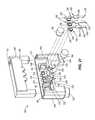
- FIG. 9Yet another example of programming behavior in the electronic building system 30 through controls is shown in FIG. 9 .
- the useris able to program behavior of the circuit by manipulating physical elements and without any code writing.
- a 9 Volt battery 114is shown and is part of the power module 34 I, which is connected to a temperature sensor module 34 J including a threshold component, followed by an audio module 34 K.
- the temperature sensor module 34 Jmay be more advanced than a traditional sensor module.
- the block 34 Jfeatures a potentiometer 118 that may be adjusted to set a temperature threshold. If the temperature detected by a temperature sensor 122 is above the set temperature threshold, the module 34 J outputs a high reading.
- an output of a high reading from the temperature sensor module 34 Jwill cause the audio module 34 K to activate and a speaker 126 to play a pre-recorded message associated with a high reading.
- this exemplary circuitcould be used by a person wishing to have an alarm to turn on the Air Conditioning. When the temperature exceeds a pre-set threshold temperature, the audio module 34 K could play back a message “time to turn on the AC!” Also, the audio module 34 K may instead be replaced with a fan module, which may activate upon receiving a high temperature reading signal from the temperature sensor module 34 J.
- the temperature sensor modulemay incorporate a mode switch 130 that can flip the behavior of the block 34 J from ‘normally-low’ to ‘normally-high’.
- a ‘normally-high’ settingwould cause the module 34 J to output a high reading except when the temperature exceeds the threshold.
- the kit 132may include a plurality of modules or blocks 34 and a substrate or mounting board 134 , upon which modules 34 may be placed, supported, and or connected.
- the mounting board 134may be any size and be made of any material. In some exemplary embodiments, the mounting board 134 is made of a non-conductive material.
- the kit 132may include a container 138 in which the modules 34 may be stored when not in use.
- the plurality of blocks 34 and substrate 134may be the beginning of a kit or library that a user adds to by creating or acquiring new modules and kits, all fitting together as part of the electronic building system 30 .
- the modules 34 L, 34 M, 34 N, 34 P, 34 Q, and 34 Rmay be uniquely configured to provide a quick visual indication to a user of each module's function.
- the modulesmay be uniquely configured in any manner and have any characteristic to identify the functionality of the modules.
- any portion of the module 34may be uniquely configured and have any characteristic to represent the unique configuration feature.
- the modulesmay have a characteristic that uniquely identifies the modules by color-coding, patterning, or may include unique structuring such as shapes, housings, interconnection or couplings, etc.
- the illustrated exemplary embodimentsdemonstrate color-coding of the connectors 38 as the exemplary manner of uniquely configuring modules to provide visual indicators as to the function of the modules.
- the modulesmay be uniquely configured in any manner and be within the spirit and scope of the present invention.
- the functionality of the modules identified by the unique configurations and characteristicsmay be any type or level of functionality.
- the unique configurationsmay indicate that the modules are input modules, power modules, wire modules, output modules, etc.
- the unique configurations of the modulesmay be more specific such as, for example, an LED module, a 9-volt battery module, a cell battery module, a potentiometer module, a switch module, a pressure sensor module, a pulse module, a button module, a vibration motor module, a wire module, etc.
- color-codingprovides the user with a quick visual confirmation of the type of module, the functionality of the module, as well as allowing the user to learn which color combinations are possible.
- the connectors 38are shaded in different manners. Shading connectors 38 in different manners to illustrate various colors is an exemplary manner of representing various colors and is not intended to be limiting. Other manners of representing different colors are contemplated and all of such are intended to be within the spirit and scope of the present invention. Additionally, the connectors 38 are capable of having any color and are not limited to the exemplary colors and associated shading included in the figures.
- wire modules 34 Lmay include orange connectors 38 L.
- orange connectors 38 Lmay connect to other orange connectors 38 L, to green connectors 38 M, 38 N of output modules ( FIG. 12 depicting a bar graph 34 M, and FIG. 13 depicting a vibration motor 34 N), and/or to pink connectors 38 P, 38 Q of input modules ( FIG. 14 depicting a pulse module 34 P, and FIG. 15 depicting a pressure sensor 34 Q), depending on the system 30 the user is attempting to build.
- Each system 30will likely require a power module ( FIG.
- kits 132depicting a wall power module 34 R), which will include blue color-coded connectors 38 R according to one exemplary embodiment.
- the kit 132may include a blue power module 34 R, one or more orange wire modules 34 L, a plurality of pink input modules 34 P, 34 Q, 34 S, 34 T, and a plurality of green output module 34 M, 34 N, 34 U, 34 V.
- Other exemplary kitsmay include any number of modules 34 including any possible functionality and be within the intended spirit and scope of the present invention.
- FIG. 18another exemplary system 30 is illustrated including a plurality of exemplary modules 34 W, 34 X, and 34 Y and a mounting board or substrate 148 upon which to couple and support the modules.
- the system 30 illustrated in FIG. 18is capable of including any type of module described herein or any other type of module having any type of functionality.
- the exemplary modules illustrated and described herein in connection with FIG. 18are not intended to be limiting.
- the mounting board 148may be any size and may be made of any material. In some exemplary embodiments, the mounting board 148 may be 4 inches by 12 inches. In other exemplary embodiments, the mounting board 148 may be made of any non-conductive material.
- the mounting board 148may be broken up or otherwise separated into smaller portions to a desired size appropriate to the desired application.
- the mounting board 148may either be made of a material and have a configuration that enables breaking or separation of the mounting board 148 into smaller portions, or the mounting board 148 may include perforations, areas of decreased thickness, or other structural characteristics that provide predetermined locations for facilitating easy breaking or separating of the mounting board 148 into smaller portions.
- modulesare adapted to have a variety of different types of functionality and include the appropriate connectors, circuit boards, and associated electrical components coupled to the circuit boards to perform the desired functionality.
- the modules shown in the illustrated exemplary embodimentare for exemplary and demonstrative purposes, and are not intended to be limiting.
- the exemplary illustrated modulesinclude a wall power module 34 W (power), a bar graph module 34 X (input), and an LED module 34 Y (output).
- each module 34 X and 34 Yare illustrated and each includes a pair of connectors 152 and a circuit board 156 appropriate to the desired functionality of the module.
- the modulewill include the appropriate electrical components to perform the desired functionality of the module.
- Each connector 152includes a housing 160 comprised of two portions 160 ′, 160 ′′ (see FIG. 21 ) coupled together, a pair of magnets 164 , and a plurality of electrical conductors 168 .
- the two portions of the housing 160may be coupled together in a variety of manners such as, for example, heat staking, ultrasonic welding, adhesion, press-fit, friction-fit, interference-fit, snap fit or other positive locking manner, etc, and may be made of a variety of different materials such as, for example, plastic (e.g., ABS plastic), or other non-conductive materials.
- a first portion 160 ′ of the housingdefines a cavity 172 for receiving the second portion 160 ′′ of the housing therein.
- the cavity 172is complementarily shaped to the second portion 160 ′′ to ensure a top surface 176 of the second portion 160 ′′ is substantially flush with a top surface 180 of the first portion 160 ′ (see FIGS. 20 and 21 ) and a side surface 184 of the second portion 160 ′′ is flush with a side surface 188 of the first portion 160 ′ when the two portions 160 ′, 160 ′′ are coupled together.
- the first portion 160 ′ of the housingalso defines a pair of magnet apertures 192 (see FIG. 21 ) in a side surface 196 thereof in which the magnets 164 are supported.
- the magnets 164are cylindrical in shape, thereby providing a circular cross-section taken along a plane perpendicular to a longitudinal extent of the magnet 164 .
- the magnet apertures 192 defined in the first portion 160 ′ of the housingare circular in shape.
- the magnets 164may having any shape and the magnet apertures 192 may similarly have any shape that complements the shape of the magnets 164 . For example, if the cross-sectional shape of the magnets is square, then the magnet apertures in the first portion of the housing may be square.
- the magnet aperturesmay have shapes that are not complementary to the shape of the magnet.
- the magnetic aperturemay be any shape that inhibits the magnet from passing through the magnetic aperture and escaping the housing 160 of the connector.
- the magnetmay be cylindrical in shape, thereby providing a circular cross-section, and the magnet aperture may be square such that the square is sized sufficiently small to inhibit the magnet from passing through the aperture.
- the first portion 160 ′ of the housingdefines electrical conductor apertures 200 in the side surface 196 thereof for receiving and supporting a portion of the electrical conductors 168 (described in more detail below).
- the electrical conductor apertures 200are circular in shape complementary to the shape of a portion of the electrical conductors 168 received therein.
- the electrical conductor apertures 200may have any shape and be complementary to the shape of a portion of the electrical conductors 168 received therein.
- the first portion 160 ′ of the housingfurther defines a plurality of conductor slots 204 (see FIG. 21 ) in a bottom surface 208 thereof for receiving the conductors 168 therein when the housing 160 is assembled.
- Each conductor slot 204includes an upper end 212 having a first dimension, a bottom end 216 having a second dimension smaller than the first dimension, and tapered side surfaces 220 tapering from large to small from the upper end 212 to the lower end 216 .
- the shape of the conductor slots 204is complementary to the shape of the electrical conductors 168 in order to provide sufficient support to the electrical conductors 168 when the housing 160 is assembled.
- the first portion 160 ′ of the housingincludes a pair of projections 224 extending downward from a bottom surface 208 thereof for coupling the connector 152 to the circuit board 156 of the module 34 .
- the projections 224are cylindrical in shape and may insert into apertures 228 (see FIG. 20 ) defined in the circuit board 156 . Subsequently to inserting the projections 224 into the circuit board apertures 228 , the projections 224 may be deformed to inhibit them from withdrawing from the apertures 228 in the circuit board 156 .
- the projections 224may be deformed in a variety of different manners such as, for example, melting or heating the projections 224 , bending, smashing, or any other manner that sufficiently deforms the projections 224 to inhibit them from withdrawing from the apertures 228 in the circuit board 156 .
- the housing 160also defines a receptacle 232 in a side surface thereof and includes a projection 236 extending from the side surface and positioned adjacent the receptacle 232 .
- a receptacle 232 and projection 236are included in each connector housing 160 and assist with proper alignment and coupling of modules 34 together.
- the receptacle 232is shaped complementary to a shape of the projection 236 such that when a projection 236 is received in the receptacle 232 the projection 236 substantially fills the receptacle 232 .
- the connectors 152When coupling two modules 34 together, the connectors 152 are aligned with the projection 236 on each connector 152 substantially aligned with the receptacle 232 on the other connector 152 , and the modules 34 are moved together until the magnetic force of the four magnets 164 on the two connectors 152 is sufficient to pull the connectors 152 together, thereby causing the projections 236 to insert into the receptacles 232 .
- the projections 236 and receptacles 232 of the connectors 152cooperate to inhibit substantial lateral and vertical movement of the modules 34 relative to one another.
- the first portion 160 ′ of the housingincludes a pair of mounting members 240 extending downward there from and adapted to engage complementarily shaped receptacles 244 defined in the mounting board 148 (see FIG. 18 ).
- the mounting members 240 and the receptacles 244are configured to provide adequate support to the modules 34 when mounted on the mounting board 148 .
- the mounting members 240have a shape comprised of a quarter of a circle and the receptacles 244 on the mounting board 148 are circular in shape.
- the two mounting members 240 on the two connectors 152form a semicircle that may friction fit into the receptacles 244 in the mounting board 148 .
- each electrical conductor 168has a spring characteristic that allows for movement of the conductors 168 as a result of forces applied thereto.
- This spring characteristic that facilitates movement of the conductors 168helps maintain contact with electrical conductors 168 on an adjacent module 34 coupled to the present module 34 during manipulation of the modules 34 . Such manipulation may result in forces applied to the modules 34 causing movement of the modules 34 relative to one another.
- each electrical conductor 168includes an engagement portion 248 (see FIG. 21 ) positioned within a respective electrical conductor aperture 200 , a coupling portion 252 extending downward and adapted to engage and electrically communicate with the circuit board 156 , and a middle portion 256 (see FIG.
- the engagement portion 248is adapted to engage an electrical conductor 168 of an adjacent module 34 coupled to the present module 34 . Due to the electrical conductor 168 being made of a conductive material, the electrical current travels through the electrical conductor 168 of the present module 34 to its circuit board 156 .
- Each electrical conductor 168includes an enlarged portion 260 (see FIG. 21 ) positioned between ends of the conductor 168 that fits into a respective conductor slot 204 .
- the enlarged portion 260has a complementary shape to the conductor slot 204 to provide vertical and horizontal support to the electrical conductor 168 when the housing 160 is assembled. In the illustrated exemplary embodiment, the enlarged portion 260 includes a tapered portion 264 (see FIG. 21 ) that complements the tapered surfaces 220 of the conductor slot 204 .
- a support member 268is coupled to two coupled together modules 34 to provide additional support to the coupled modules 34 .
- the support member 268is used instead of the mounting board 148 to provide modules 34 with additional support.
- the support member 268may be configured to allow both the support member 268 and the mounting board 148 to provide support to coupled together modules 34 .
- the support member 268includes a pair of receptacles 280 defined in a top surface 276 thereof for receiving mounting members 240 of coupled together modules 34 .
- the receptacles 280 in the support members 268are similarly sized, shaped and spaced apart as the receptacles 244 in the mounting board 148 .
- the support member 268also has a height H that, when two modules 34 are coupled to each other and to the support member 268 , a top surface 276 of the support member 268 is substantially flush with and mates or engages with a bottom surface 288 of the housing 160 .
- the support member 268includes a width W 1 that is substantially similar to a width W 2 of two coupled together connectors 152 and a length L 1 that is substantially similar to a length L 2 of the two coupled together modules 34 .
- the support member 268may have configurations different than the illustrated exemplary embodiment as long as the support member 268 provides support to coupled together modules 34 .
- a support member 268may be coupled to each pair of coupled together connectors 152 in the system 30 .
- the system 30may include any number of support members 268 therein and be within the intended spirit and scope of the present invention.
- the exemplary systems 30 disclosed hereinare adapted to cooperate with other types of systems to bring the functionality and features of the exemplary systems 30 to the other types of systems.
- the exemplary systems 30may cooperate with any type of other system and be within the intended spirit and scope of the present invention.
- an exemplary mounting board 148 of an exemplary system 30 of the present inventionis shown cooperating with a toy building block system 292 such as, for example, a LEGO® building block system 292 .
- the illustrated exemplary systemsare not intended to be limiting, but, rather, are for exemplary and demonstrative purposes.
- the mounting board 148is configured to cooperate with the exemplary LEGO building block system 292 and, in particular, is configured to couple to a LEGO building block system 292 .
- a first side 296 of the mounting board 148e.g., a top side
- a second side 298 of the mounting board 148includes a plurality of projections 300 having cavities 304 defined therein that are appropriately spaced from one another to facilitate coupling to the LEGO building block system 292 .
- the systems 30 of the present inventionmay couple to any type of other systems and, accordingly, the second side 298 of the mounting board 148 may be configured in any manner to accommodate any type of other system to which the mounting board 148 is intended to couple.
- modulesmay be coupled together to achieve various functionalities of the systems.
- Modulesmay be coupled in a cascading manner in which the inclusion of one module in the system may affect the functionality of downstream modules in a first manner and inclusion of a different module in the system may affect the function of downstream modules in another manner different than the first manner. That is, modules coupled together in a system may have dependencies upon one another to affect functionality thereof and of the entire system.
- a simple example to demonstrate this concept, but is not intended to be limiting,comprises a system include three modules: A power module, a button module, and an LED module. The button module and the LED module are dependent on the power module, and the LED module is dependent on the button module.
Landscapes
- Toys (AREA)
Abstract
Description
Claims (20)
Priority Applications (32)
| Application Number | Priority Date | Filing Date | Title |
|---|---|---|---|
| US13/593,891US9019718B2 (en) | 2011-08-26 | 2012-08-24 | Modular electronic building systems with magnetic interconnections and methods of using the same |
| AU201310848FAU347408S (en) | 2012-08-24 | 2013-02-22 | Connector for modular electronic building system |
| CN201380004224.3ACN103974753B (en) | 2012-08-24 | 2013-08-26 | Modular electronics building system utilizing magnetic interconnects and method of use |
| EP18184425.9AEP3470127B1 (en) | 2012-08-24 | 2013-08-26 | Modular electronic building systems with magnetic interconnections and methods of using the same |
| RU2019111471ARU2792655C2 (en) | 2012-08-24 | 2013-08-26 | Modular electronic building systems with magnetic interconnections and methods of their application |
| CN201610740452.2ACN106215433B (en) | 2012-08-24 | 2013-08-26 | System and its application method are built using the module electronic of magnetism interconnection |
| NZ704976ANZ704976A (en) | 2012-08-24 | 2013-08-26 | Apparatus for modular electronic building systems |
| CN201610730917.6ACN106215432B (en) | 2012-08-24 | 2013-08-26 | System and its application method are built using the module electronic of magnetism interconnection |
| CA2883216ACA2883216A1 (en) | 2012-08-24 | 2013-08-26 | Modular electronic building systems with magnetic interconnections and methods of using the same |
| SG11201501308PASG11201501308PA (en) | 2012-08-24 | 2013-08-26 | Modular electronic building systems with magnetic interconnections and methods of using the same |
| EP13831481.0AEP2888019B1 (en) | 2012-08-24 | 2013-08-26 | Modular electronic building systems with magnetic interconnections and methods of using the same |
| MX2015002306AMX377362B (en) | 2012-08-24 | 2013-08-26 | MODULAR ELECTRONIC CONSTRUCTION SYSTEMS WITH MAGNETIC INTERCONNECTIONS AND METHODS OF USING THE SAME. |
| JP2015528712AJP2015526208A (en) | 2012-08-24 | 2013-08-26 | Modular electronic building system with magnetic interconnection and method of use thereof |
| BR112015003911ABR112015003911A8 (en) | 2012-08-24 | 2013-08-26 | modular electronic building systems with magnetic interconnections and methods of using them |
| US13/975,923US9597607B2 (en) | 2011-08-26 | 2013-08-26 | Modular electronic building systems with magnetic interconnections and methods of using the same |
| CN201910759040.7ACN110465103B (en) | 2012-08-24 | 2013-08-26 | Modular electronic construction system using magnetic interconnection and method of use thereof |
| HK15100629.2AHK1200136B (en) | 2012-08-24 | 2013-08-26 | Modular electronic building systems with magnetic interconnections and methods of using the same |
| AU2013305556AAU2013305556B2 (en) | 2012-08-24 | 2013-08-26 | Modular electronic building systems with magnetic interconnections and methods of using the same |
| PCT/US2013/056599WO2014032043A1 (en) | 2012-08-24 | 2013-08-26 | Modular electronic building systems with magnetic interconnections and methods of using the same |
| KR1020157007424AKR20150086231A (en) | 2012-08-24 | 2013-08-26 | Modular electronic building systems with magnetic interconnections and methods of using the same |
| RU2015110259ARU2686521C2 (en) | 2012-08-24 | 2013-08-26 | Modular electronic building systems with magnetic interconnections and methods of using same |
| CN201610738594.5ACN106267846B (en) | 2012-08-24 | 2013-08-26 | System and its application method are built using the module electronic of magnetism interconnection |
| MX2020012141AMX2020012141A (en) | 2012-08-24 | 2015-02-20 | Modular electronic building systems with magnetic interconnections and methods of using the same. |
| US14/696,922US9419378B2 (en) | 2011-08-26 | 2015-04-27 | Modular electronic building systems with magnetic interconnections and methods of using the same |
| US15/228,707US9831599B2 (en) | 2011-08-26 | 2016-08-04 | Modular electronic building systems with magnetic interconnections and methods of using the same |
| US15/463,510US10244630B2 (en) | 2011-08-26 | 2017-03-20 | Modular electronic building systems with magnetic interconnections and methods of using the same |
| US15/822,636US10256568B2 (en) | 2011-08-26 | 2017-11-27 | Modular electronic building systems with magnetic interconnections and methods of using the same |
| AU2018203907AAU2018203907B2 (en) | 2012-08-24 | 2018-06-02 | Modular electronic building systems with magnetic interconnections and methods of using the same |
| US16/360,827US11330714B2 (en) | 2011-08-26 | 2019-03-21 | Modular electronic building systems with magnetic interconnections and methods of using the same |
| US16/373,267US20190296482A1 (en) | 2011-08-26 | 2019-04-02 | Modular electronic building systems with magnetic interconnections and methods of using the same |
| JP2019141870AJP2019181269A (en) | 2012-08-24 | 2019-08-01 | Modular electronic building systems with magnetic interconnections and methods of using the same |
| US17/662,533US12349275B2 (en) | 2011-08-26 | 2022-05-09 | Modular electronic building systems with magnetic interconnections and methods of using the same |
Applications Claiming Priority (2)
| Application Number | Priority Date | Filing Date | Title |
|---|---|---|---|
| US201161527860P | 2011-08-26 | 2011-08-26 | |
| US13/593,891US9019718B2 (en) | 2011-08-26 | 2012-08-24 | Modular electronic building systems with magnetic interconnections and methods of using the same |
Related Child Applications (2)
| Application Number | Title | Priority Date | Filing Date |
|---|---|---|---|
| US13/975,923Continuation-In-PartUS9597607B2 (en) | 2011-08-26 | 2013-08-26 | Modular electronic building systems with magnetic interconnections and methods of using the same |
| US14/696,922ContinuationUS9419378B2 (en) | 2011-08-26 | 2015-04-27 | Modular electronic building systems with magnetic interconnections and methods of using the same |
Publications (2)
| Publication Number | Publication Date |
|---|---|
| US20130050958A1 US20130050958A1 (en) | 2013-02-28 |
| US9019718B2true US9019718B2 (en) | 2015-04-28 |
Family
ID=47743461
Family Applications (5)
| Application Number | Title | Priority Date | Filing Date |
|---|---|---|---|
| US13/593,891Active2033-08-20US9019718B2 (en) | 2011-08-26 | 2012-08-24 | Modular electronic building systems with magnetic interconnections and methods of using the same |
| US14/696,922ActiveUS9419378B2 (en) | 2011-08-26 | 2015-04-27 | Modular electronic building systems with magnetic interconnections and methods of using the same |
| US15/228,707ActiveUS9831599B2 (en) | 2011-08-26 | 2016-08-04 | Modular electronic building systems with magnetic interconnections and methods of using the same |
| US15/822,636ActiveUS10256568B2 (en) | 2011-08-26 | 2017-11-27 | Modular electronic building systems with magnetic interconnections and methods of using the same |
| US16/373,267AbandonedUS20190296482A1 (en) | 2011-08-26 | 2019-04-02 | Modular electronic building systems with magnetic interconnections and methods of using the same |
Family Applications After (4)
| Application Number | Title | Priority Date | Filing Date |
|---|---|---|---|
| US14/696,922ActiveUS9419378B2 (en) | 2011-08-26 | 2015-04-27 | Modular electronic building systems with magnetic interconnections and methods of using the same |
| US15/228,707ActiveUS9831599B2 (en) | 2011-08-26 | 2016-08-04 | Modular electronic building systems with magnetic interconnections and methods of using the same |
| US15/822,636ActiveUS10256568B2 (en) | 2011-08-26 | 2017-11-27 | Modular electronic building systems with magnetic interconnections and methods of using the same |
| US16/373,267AbandonedUS20190296482A1 (en) | 2011-08-26 | 2019-04-02 | Modular electronic building systems with magnetic interconnections and methods of using the same |
Country Status (1)
| Country | Link |
|---|---|
| US (5) | US9019718B2 (en) |
Cited By (25)
| Publication number | Priority date | Publication date | Assignee | Title |
|---|---|---|---|---|
| US9312633B1 (en)* | 2014-10-20 | 2016-04-12 | Nanoport Technology Inc. | Connectors with movable magnetic components and method of connecting devices |
| US20160219740A1 (en)* | 2015-01-27 | 2016-07-28 | Euchner Gmbh + Co. Kg | Modular Arrangement with at Least One Base Module |
| US9419378B2 (en)* | 2011-08-26 | 2016-08-16 | Littlebits Electronics Inc. | Modular electronic building systems with magnetic interconnections and methods of using the same |
| US20160249478A1 (en)* | 2015-02-20 | 2016-08-25 | Microduino Inc. | Electrical modules and modular electronic building systems |
| US20160327728A1 (en)* | 2014-01-10 | 2016-11-10 | Novomatic Ag | Lighting system |
| US9502819B2 (en) | 2013-11-13 | 2016-11-22 | Nanoport Technology Inc. | Methods and apparatus for connecting devices with stacked magnetic connectors |
| US20170036132A1 (en)* | 2014-01-25 | 2017-02-09 | Hangzhou Suze Electronic Technology Co., Ltd. | Compatible and Magnetic Absorption-Type Electronic Building Block |
| US20170042048A1 (en)* | 2015-08-06 | 2017-02-09 | Euchner Gmbh & Co. Kg | Module Arrangement |
| US9597607B2 (en) | 2011-08-26 | 2017-03-21 | Littlebits Electronics Inc. | Modular electronic building systems with magnetic interconnections and methods of using the same |
| US9653844B1 (en) | 2016-05-12 | 2017-05-16 | Nanoport Technology Inc. | Electronic device connectors with rotatable anchors |
| US20170149171A1 (en)* | 2015-11-21 | 2017-05-25 | Nanoport Technology Inc. | Magnetic connectors for physical connection and data and power exchange between devices |
| US9774136B2 (en) | 2015-12-02 | 2017-09-26 | Nanoport Technology Inc. | Self-aligning connector |
| US20170291116A1 (en)* | 2016-04-08 | 2017-10-12 | Tenka Labs, Inc. | Circuit blocks |
| US9825399B2 (en)* | 2016-03-07 | 2017-11-21 | Luxrobo | Module assembly and connector and electronic device |
| US9907195B2 (en) | 2015-09-28 | 2018-02-27 | Shahram MONTAZERI | Apparatus having connection module for use with electrical module |
| US10155153B2 (en) | 2009-08-06 | 2018-12-18 | Littlebits Electronics, Inc. | Puzzle with conductive path |
| US10250954B2 (en)* | 2017-04-18 | 2019-04-02 | Buerkert Werke Gmbh & Co. Kg | Electronics module for coupling to a module arrangement and module arrangement |
| US20190190193A1 (en)* | 2017-12-18 | 2019-06-20 | Littlebits Electronics Inc. | Modular electronic building systems and methods of using the same |
| US20190232185A1 (en)* | 2018-01-29 | 2019-08-01 | Eagle Technology Co., Ltd. | Electrical building block |
| US20190280428A1 (en)* | 2018-03-07 | 2019-09-12 | Xcelsis Corporation | Configurable smart object system with magnetic contacts and magnetic assembly |
| US20200161803A1 (en)* | 2018-11-20 | 2020-05-21 | Ubtech Robotics Corp Ltd | Electronic building block and building block kit having the same |
| US11330714B2 (en) | 2011-08-26 | 2022-05-10 | Sphero, Inc. | Modular electronic building systems with magnetic interconnections and methods of using the same |
| US11791589B2 (en)* | 2017-12-18 | 2023-10-17 | Sphero, Inc. | Modular electronic building systems and methods of using the same |
| US20240128682A1 (en)* | 2022-10-13 | 2024-04-18 | Michael Sansur | Magnetically Coupled Circuits |
| EP4232176A4 (en)* | 2020-10-25 | 2024-10-02 | Qubee Ltd. | ELECTRICALLY CONDUCTIVE BUILDING BLOCKS WITH ANTISYMMETRICAL CONTACT MECHANISMS |
Families Citing this family (60)
| Publication number | Priority date | Publication date | Assignee | Title |
|---|---|---|---|---|
| US20150201858A1 (en)* | 2008-08-15 | 2015-07-23 | Global Cardiac Monitors, Inc. | Diagnostic device for remote sensing and transmitting biophysiological signals |
| US8742814B2 (en) | 2009-07-15 | 2014-06-03 | Yehuda Binder | Sequentially operated modules |
| USD732475S1 (en)* | 2012-11-19 | 2015-06-23 | Littlebits Electronics Inc. | Connector for modular electronic building system |
| US8798675B2 (en) | 2012-09-03 | 2014-08-05 | iBlaidZ, Inc. | System of stacked devices |
| US10008125B2 (en) | 2013-01-03 | 2018-06-26 | East Carolina University | Methods, systems, and devices for multi-user treatment for improvement of reading comprehension using frequency altered feedback |
| USD716375S1 (en)* | 2013-01-03 | 2014-10-28 | East Carolina University | Multi-user reading comprehension therapy device |
| US10173143B2 (en)* | 2013-01-31 | 2019-01-08 | Joshua Willard Ferguson | Magnetic construction system and method |
| US9703321B2 (en) | 2013-07-09 | 2017-07-11 | I-Blades, Inc. | Snap on wearable module |
| CN103316485A (en)* | 2013-07-21 | 2013-09-25 | 王竹泉 | Connecting device for splicing building block members and electronic components of bare printed circuit board (PCB) |
| US9312632B2 (en)* | 2013-09-27 | 2016-04-12 | Genesis Technology Usa, Inc. | Heat resistant magnetic electrical connector |
| EP3572888A1 (en)* | 2014-02-26 | 2019-11-27 | Zen Ecosystems IP Pty Ltd | User interface for a consumer product system |
| US11772003B2 (en) | 2014-02-28 | 2023-10-03 | Alexander Kokhan | Electrical construction toy system |
| US9555326B2 (en) | 2014-03-11 | 2017-01-31 | Microsoft Technology Licensing, Llc | Gaming system for modular toys |
| US9592443B2 (en)* | 2014-03-11 | 2017-03-14 | Microsoft Technology Licensing, Llc | Data store for a modular assembly system |
| US9531118B2 (en) | 2014-07-10 | 2016-12-27 | Norman R. Byrne | Electrical power coupling with magnetic connections |
| US10195538B2 (en) | 2014-10-08 | 2019-02-05 | DXTR Tactile IvS | Interactive learning blocks |
| US20170007938A1 (en)* | 2015-02-13 | 2017-01-12 | Playmonster, Llc | Miniature Electronic Customizable Room Building Toy Components |
| WO2016187517A1 (en)* | 2015-05-20 | 2016-11-24 | Robo Technologies Gmbh | Connecting structures in a modular construction kit |
| KR20180048622A (en)* | 2015-07-20 | 2018-05-10 | 브릭소 스마트 토이스 리미티드 | Circuit building system |
| DE102015215170A1 (en)* | 2015-08-07 | 2017-02-09 | Brose Fahrzeugteile Gmbh & Co. Kommanditgesellschaft, Coburg | A massage device for a vehicle seat, vehicle seat and method for manufacturing a vehicle seat |
| US9782688B2 (en) | 2015-10-23 | 2017-10-10 | Kma Concepts Limited | Linkable toy elements with enhanced acoustic properties |
| US10177507B2 (en) | 2016-02-12 | 2019-01-08 | Norman R. Byrne | Electrical power load switch with connection sensor |
| US20170257146A1 (en)* | 2016-03-01 | 2017-09-07 | Nanoport Technology Inc. | Facilitating alignment of wireless elements for ultra short range wireless interaction |
| CN105513474A (en)* | 2016-03-02 | 2016-04-20 | 成都麦克星球教育科技有限公司 | Electronic building block module and electronic building block teaching aid |
| WO2017161127A1 (en) | 2016-03-16 | 2017-09-21 | The Trustees Of The University Of Pennsylvania | Systems of stacking interlocking blocks |
| TWI582605B (en)* | 2016-05-03 | 2017-05-11 | 廣達電腦股份有限公司 | Identifiable modular electronic device |
| US10148036B2 (en) | 2016-06-23 | 2018-12-04 | Vanderbilt University | Multi-platform modular device |
| US10024905B2 (en) | 2016-10-06 | 2018-07-17 | International Business Machines Corporation | Implementing user configurable probing using magnetic connections and PCB features |
| MX371369B (en) | 2016-10-07 | 2020-01-28 | Norman R Byrne | Electrical power cord with intelligent switching. |
| CN108024471A (en)* | 2016-11-04 | 2018-05-11 | 酷比客有限公司 | Circuit module structure |
| US20180205569A1 (en)* | 2017-01-12 | 2018-07-19 | Roger Wagner | Method and apparatus for bidirectional control connecting hardware device action with url-based web navigation |
| DK3589380T3 (en)* | 2017-03-03 | 2021-08-09 | Lego As | Interactive modular building element and a modular building system with interactive modular building elements |
| US10610773B2 (en)* | 2017-03-06 | 2020-04-07 | Suffuse Inc. | Interactive digital platform device and method |
| TWI639283B (en)* | 2017-08-08 | 2018-10-21 | 碩天科技股份有限公司 | Adapter and using method thereof |
| US20190097362A1 (en)* | 2017-09-26 | 2019-03-28 | Xcelsis Corporation | Configurable smart object system with standard connectors for adding artificial intelligence to appliances, vehicles, and devices |
| US10252176B1 (en)* | 2017-10-02 | 2019-04-09 | Elenco Electronics, Inc. | Adapter for connecting a toy building block to a snap-together electronic toy |
| TWI650633B (en) | 2017-10-06 | 2019-02-11 | 財團法人國家實驗研究院 | Modular electronic combination device |
| US20190280421A1 (en)* | 2018-03-07 | 2019-09-12 | Xcelsis Corporation | Configurable smart object system with grid or frame-based connectors |
| US10862252B2 (en)* | 2018-05-04 | 2020-12-08 | The Ricker Lyman Robotic Company, Inc. | Surface-contact ethernet connector, network equipment chassis including the same and operating method thereof |
| US20200019386A1 (en)* | 2018-07-11 | 2020-01-16 | Jay Wright | Interlocking blocks for the creation of computer code systems via three dimensional representation using virtual representation, holography, and enhanced reality |
| US11336067B2 (en)* | 2018-09-14 | 2022-05-17 | Hewlett-Packard Development Company, L.P. | Hinge adapters |
| CN111443308B (en)* | 2018-12-28 | 2022-09-23 | 深圳市优必选科技有限公司 | Magnetic type steering engine and hot plug detection circuit and orientation detection circuit thereof |
| US11616844B2 (en) | 2019-03-14 | 2023-03-28 | Sphero, Inc. | Modular electronic and digital building systems and methods of using the same |
| US11424561B2 (en) | 2019-07-03 | 2022-08-23 | Norman R. Byrne | Outlet-level electrical energy management system |
| JP7210415B2 (en)* | 2019-10-11 | 2023-01-23 | ヒロセ電機株式会社 | electrical connector |
| CN111146641A (en)* | 2019-12-28 | 2020-05-12 | 深圳市优必选科技股份有限公司 | A magnetic connector, circuit and robot |
| TWI728686B (en)* | 2020-02-06 | 2021-05-21 | 香港商億奇生物科技責任有限公司 | Load adaptive device and hand-made circuit module |
| JP6974591B1 (en)* | 2020-02-17 | 2021-12-01 | ガンホー・オンライン・エンターテイメント株式会社 | Processing equipment, programs, and methods |
| US20220001292A1 (en)* | 2020-06-18 | 2022-01-06 | Saifeng Chen | Programmable toy building blocks system |
| US20230231397A1 (en)* | 2022-01-14 | 2023-07-20 | Atop Technologies, Inc. | Battery powered system and battery powered method |
| US12029996B2 (en) | 2022-05-06 | 2024-07-09 | Elenco Electronics, Llc | Electronic toy brick |
| US12235683B2 (en) | 2022-10-18 | 2025-02-25 | Dell Products L.P. | Information handling system display rapid panel assembly and repair |
| US12306676B2 (en) | 2022-10-18 | 2025-05-20 | Dell Products L.P. | Information handling system keyboard with rapid assembly and disassembly to aid recycling |
| US12273609B2 (en) | 2022-10-18 | 2025-04-08 | Dell Products L.P. | Camera sensor and lens housing structure for enhanced manufacture assembly and repair |
| US12306677B2 (en) | 2022-10-18 | 2025-05-20 | Dell Products L.P. | Information handling system with rapid assembly and disassembly to aid recycling |
| US11856719B1 (en) | 2022-10-18 | 2023-12-26 | Dell Products L.P. | Information handling system mouse with rapid assembly and disassembly to aid recycling |
| US12284429B2 (en) | 2022-10-18 | 2025-04-22 | Dell Products L.P. | Camera housing structure for enhanced manufacture assembly and repair |
| US12245372B2 (en) | 2022-10-18 | 2025-03-04 | Dell Products L.P. | Information handling system and peripheral printed circuit board having non-homogeneous substrate material and integrated thermal solution |
| US12085993B2 (en) | 2022-10-18 | 2024-09-10 | Dell Products L.P. | Information handling system coupling device for improved assembly, disassembly and repair |
| US11650671B1 (en) | 2022-10-18 | 2023-05-16 | Dell Products L.P. | Information handling system keyboard with rapid assembly and disassembly to aid recycling |
Citations (46)
| Publication number | Priority date | Publication date | Assignee | Title |
|---|---|---|---|---|
| US3862512A (en) | 1968-08-08 | 1975-01-28 | Georg Vogel | Sets of building blocks of different sizes |
| USD244632S (en) | 1975-03-25 | 1977-06-07 | Interlego A.G. | Toy construction piece |
| US4552541A (en) | 1983-02-14 | 1985-11-12 | Interlego Ag | Toy building block with electrical contacting portions |
| US4743202A (en) | 1984-08-03 | 1988-05-10 | Interlego A.G. | Current-carrying building element |
| US4878848A (en) | 1988-07-14 | 1989-11-07 | Independent Technologies, Inc. | 110 Block adapter |
| US4964833A (en) | 1989-06-02 | 1990-10-23 | Mass-Set Kabushiki Kaisha | Toy construction blocks with connectors |
| US4978317A (en)* | 1989-03-27 | 1990-12-18 | Alan Pocrass | Connector with visual indicator |
| USD324551S (en) | 1990-12-04 | 1992-03-10 | Interlego A.G. | Toy construction piece |
| USD335508S (en) | 1990-12-04 | 1993-05-11 | Interlego A.G. | Element for a toy building set |
| US5345221A (en)* | 1992-06-02 | 1994-09-06 | John Michael Pons | Arm alarm system |
| USD352750S (en) | 1993-09-22 | 1994-11-22 | Interlego A.G. | Building plate for a toy building set |
| USD354318S (en) | 1993-09-22 | 1995-01-10 | Interlego A.G. | Element for a toy building set |
| USD365756S (en) | 1993-09-22 | 1996-01-02 | Interlego Ag | Lid for a container |
| USD370035S (en) | 1994-09-29 | 1996-05-21 | Interlego Ag | Toy building element |
| USD371583S (en) | 1995-09-14 | 1996-07-09 | Interlego Ag | Toy building element |
| USD374257S (en) | 1994-09-29 | 1996-10-01 | Interlego Ag | Toy building element |
| US5563771A (en)* | 1993-12-15 | 1996-10-08 | Itt Corporation | IC card with board positioning means |
| USD378837S (en) | 1995-09-14 | 1997-04-15 | Interlego Ag | Toy building element |
| USD385926S (en) | 1996-09-17 | 1997-11-04 | Interlego Ag | Toy building element |
| USD389408S (en) | 1993-09-22 | 1998-01-20 | Interlego Ag | Lid for a container |
| US6099353A (en) | 1998-06-02 | 2000-08-08 | Hon Hai Precision Ind. Co., Ltd. | IC card connector |
| US6102766A (en) | 1996-09-17 | 2000-08-15 | Interlego Ag | Toy building set |
| USD473849S1 (en) | 2002-07-23 | 2003-04-29 | Hon Hai Precision Ind. Co., Ltd. | Electrical connector |
| US6634920B1 (en) | 1997-09-10 | 2003-10-21 | Interlego Ag | Thermoformed toy building plate |
| US6682230B1 (en) | 2000-08-09 | 2004-01-27 | Berg Technology, Inc. | Optical connector and printed circuit board assembly with movable connection |
| US6727177B1 (en)* | 2001-10-18 | 2004-04-27 | Lsi Logic Corporation | Multi-step process for forming a barrier film for use in copper layer formation |
| US6761609B1 (en) | 1999-09-06 | 2004-07-13 | Interlego Ag | Toy building set with flexible toy building sheet element |
| US20070072442A1 (en)* | 2005-09-26 | 2007-03-29 | Apple Computer, Inc. | Electromagnetic connector for electronic device |
| US20070173095A1 (en) | 2006-01-20 | 2007-07-26 | Rifael Bin-Nun | Reusable block and fastener system |
| US20080166926A1 (en) | 2007-01-06 | 2008-07-10 | Arthur Seymour | Stackable electonic blocks and a method for stacking the same |
| USD576208S1 (en) | 2007-01-19 | 2008-09-02 | Stefano Quercetti | Drawing plate |
| USD585096S1 (en) | 2007-09-29 | 2009-01-20 | Youth Toy Enterprise Co., Ltd. | Building block board |
| US7541907B2 (en)* | 2005-11-07 | 2009-06-02 | High Tech Computer Corp. | Auto-aligning and connecting structure between electronic device and accessory |
| US7666054B2 (en) | 2006-10-16 | 2010-02-23 | K'nex Limited Partnership Group | Offset matrix adapter for toy construction sets |
| USD614250S1 (en) | 2009-01-27 | 2010-04-20 | Lego A/S | Element of a construction set |
| US20100151738A1 (en) | 2008-12-15 | 2010-06-17 | Ting-Shuo Chou | Brick assembly with automatically recognizing connecting relationships |
| US20100311300A1 (en) | 2007-10-11 | 2010-12-09 | Lego A/S | toy construction system |
| US20110059652A1 (en) | 2009-09-10 | 2011-03-10 | Amphenol Corporation | Multi-pathway connector for circuit boards |
| US20110263145A1 (en) | 2008-06-05 | 2011-10-27 | Kim Kyung T | Multi-circuit receptacle shutter assembly |
| USD658586S1 (en) | 2010-12-15 | 2012-05-01 | Cheng Uei Precision Industry Co., Ltd. | Pogo pin connector |
| US20120135613A1 (en)* | 2007-06-15 | 2012-05-31 | Microsoft Corporation | Electrical connection between devices |
| US8491312B2 (en)* | 2009-02-02 | 2013-07-23 | Apex Technologies, Inc. | Flexible magnetic interconnects |
| US8576031B2 (en)* | 2010-09-17 | 2013-11-05 | Apple Inc. | Consumer product system |
| US20130343025A1 (en) | 2011-08-26 | 2013-12-26 | Littlebits Electronics Inc. | Modular electronic building systems with magnetic interconnections and methods of using the same |
| US20140038466A1 (en) | 2012-08-03 | 2014-02-06 | Honeywell International Inc. | Module connector for uninterrupted communication |
| WO2014032043A1 (en) | 2012-08-24 | 2014-02-27 | Aya Bdeir | Modular electronic building systems with magnetic interconnections and methods of using the same |
Family Cites Families (389)
| Publication number | Priority date | Publication date | Assignee | Title |
|---|---|---|---|---|
| US2493697A (en) | 1946-08-19 | 1950-01-03 | Raczkowski Edward | Profile building puzzle |
| US2879685A (en) | 1955-05-31 | 1959-03-31 | Page Mark | Musical squeeze blocks |
| US3005282A (en) | 1958-01-28 | 1961-10-24 | Interlego Ag | Toy building brick |
| US3034254A (en) | 1958-03-25 | 1962-05-15 | Interlego Ag | Toy building sets and building blocks |
| US2947914A (en) | 1958-09-08 | 1960-08-02 | Pacific Mercury Television Mfg | Electronic apparatus |
| US3008245A (en) | 1960-10-12 | 1961-11-14 | Howard O Meuche | Educational kit for instruction and testing of electrical circuits |
| US3205407A (en) | 1962-03-05 | 1965-09-07 | Vry Technical Inst Inc De | Device for constructing electrical apparatus |
| US3594689A (en) | 1967-09-23 | 1971-07-20 | Hopt Kg R & E | Building block for electrical or electronic construction kits |
| DE1625370C3 (en) | 1967-12-01 | 1974-08-08 | Walter 8852 Rain Heubl | Pluggable toy building block |
| US3553438A (en) | 1969-07-18 | 1971-01-05 | Sylvania Electric Prod | Mark sensing system |
| US3659219A (en) | 1970-01-21 | 1972-04-25 | Us Air Force | Discrete random voltage generator |
| US3640018A (en) | 1970-05-18 | 1972-02-08 | Stanley Light | Knockdown structural toys |
| JPS4828085U (en) | 1971-08-10 | 1973-04-05 | ||
| BE788766A (en) | 1971-09-23 | 1973-01-02 | Bunker Ramo | ELECTRICAL PASS-THROUGH ASSEMBLIES |
| US4158921A (en) | 1971-12-29 | 1979-06-26 | Stolpen Beulah H | Educational teaching and self-correcting apparatus adaptable to a variety of subject matters |
| US3863931A (en) | 1973-08-24 | 1975-02-04 | Brian R Forsyth | Electrical crossword puzzle |
| US4021252A (en) | 1973-10-31 | 1977-05-03 | American Can Company | Jet printing ink composition |
| US3877028A (en) | 1974-02-22 | 1975-04-08 | Gte Automatic Electric Lab Inc | Pcm encoder-decoder apparatus |
| US3970805A (en) | 1974-02-22 | 1976-07-20 | Gte Automatic Electric (Canada) Limited | Active hybrid circuit |
| US4064377A (en) | 1976-03-11 | 1977-12-20 | Wescom Switching, Inc. | Electronic hybrid and hybrid repeater |
| US4053159A (en) | 1976-05-06 | 1977-10-11 | Kulak Walter J | Method for framing a jig-saw puzzle |
| DE2655602C2 (en) | 1976-12-08 | 1982-12-02 | Vereinigte Edelstahlwerke AG (VEW) Wien AT Niederlassung Vereinigte Edelstahlwerke AG (VEW) Verkaufsniederlassung Büderich, 4005 Meerbusch | Method and apparatus for making blocks |
| US4314236A (en) | 1977-01-12 | 1982-02-02 | Atari, Inc. | Apparatus for producing a plurality of audio sound effects |
| US4183173A (en) | 1978-03-28 | 1980-01-15 | Takara Co., Ltd. | Toy assembly with interchangeable parts and detachable appendages |
| US4516260A (en) | 1978-04-28 | 1985-05-07 | Texas Instruments Incorporated | Electronic learning aid or game having synthesized speech |
| US4233778A (en) | 1978-07-19 | 1980-11-18 | Lemelson Jerome H | Modular toy |
| US4181824A (en) | 1978-10-10 | 1980-01-01 | Bell Telephone Laboratories, Incorporated | Balancing impedance circuit |
| US4211456A (en) | 1979-01-31 | 1980-07-08 | Schick Laboratories, Inc. | Magnetic electrical connectors |
| US4285563A (en) | 1979-07-26 | 1981-08-25 | Communications Technology Corporation | Cable connector and cap shoes therefor |
| USD267895S (en) | 1980-04-10 | 1983-02-08 | Patrick Petrie | Puzzle |
| US4376538A (en) | 1980-09-22 | 1983-03-15 | Keenan Michael P | Educational game for construction and identifying electrical and electronic circuits |
| US4323243A (en) | 1980-10-20 | 1982-04-06 | Marvin Glass & Associates | Electrical board game device |
| US4348191A (en) | 1980-10-29 | 1982-09-07 | Lipsitz Barry R | Electronic game board |
| IL63231A0 (en) | 1981-07-03 | 1981-10-30 | Yechiel Salit | Kit for assembling electrical circuits |
| US4556272A (en) | 1981-10-07 | 1985-12-03 | Allied Corporation | Flat cable connector |
| US4542784A (en) | 1982-04-01 | 1985-09-24 | Planning Research Corporation | Retention and cooling of plug-in electronic modules in a high shock and vibration environment |
| US4538675A (en) | 1982-04-01 | 1985-09-03 | Planning Research Corporation | Retention and cooling of plug-in electronic modules in a high shock and vibration environment |
| US4456321A (en) | 1982-04-19 | 1984-06-26 | General Electric Company | Two-piece, push-on type grounding clip |
| US4496149A (en) | 1982-11-10 | 1985-01-29 | Schwartzberg Robert B | Game apparatus utilizing controllable audio signals |
| ZA84690B (en) | 1983-02-14 | 1984-09-26 | Interlego Ag | Building blocks for construction models,especially toy building blocks |
| EP0135633B1 (en) | 1983-09-29 | 1986-12-30 | Lee, Lan-Ying | A combinative electronic circuit element with multidirectionally adjustable joints |
| KR850004274A (en) | 1983-12-13 | 1985-07-11 | 원본미기재 | Method for preparing erythropoietin |
| US4546267A (en) | 1984-01-11 | 1985-10-08 | Steven Urfirer | Modular equipment connection |
| US4547027A (en) | 1984-02-21 | 1985-10-15 | Itt Corporation | Modular swivel connector |
| US4510210A (en) | 1984-05-25 | 1985-04-09 | Ford Motor Company | Internal-integral sodium return line for sodium heat engine |
| US4606732A (en) | 1984-06-15 | 1986-08-19 | Ronald Lyman | Interlocking toy building blocks with interconnecting, releasable hinges |
| US4712184A (en) | 1984-09-12 | 1987-12-08 | Haugerud Albert R | Computer controllable robotic educational toy |
| US4578649A (en) | 1985-02-04 | 1986-03-25 | Motorola, Inc. | Random voltage source with substantially uniform distribution |
| JPS6260065U (en) | 1985-10-02 | 1987-04-14 | ||
| IL81146A (en) | 1986-01-26 | 1990-04-29 | Avish Jacob Weiner | Sound-producing amusement or educational devices |
| IN168303B (en) | 1986-02-05 | 1991-03-09 | Interlego Ag | |
| JPH0419739Y2 (en) | 1986-02-10 | 1992-05-06 | ||
| GB8608589D0 (en) | 1986-04-09 | 1986-05-14 | Katable Co Ltd | Building block |
| US4736367A (en) | 1986-12-22 | 1988-04-05 | Chrysler Motors Corporation | Smart control and sensor devices single wire bus multiplex system |
| US4796891A (en) | 1987-02-02 | 1989-01-10 | Applied Design Laboratories, Inc. | Musical puzzle using sliding tiles |
| US4840602A (en) | 1987-02-06 | 1989-06-20 | Coleco Industries, Inc. | Talking doll responsive to external signal |
| US4874176A (en) | 1987-03-31 | 1989-10-17 | Seymour Auerbach | Three-dimensional puzzle |
| US4853884A (en) | 1987-09-11 | 1989-08-01 | Motorola, Inc. | Random number generator with digital feedback |
| GB2210722B (en) | 1987-10-08 | 1992-03-25 | Video Technology Electronics L | Electronic instructional apparatus |
| US6940783B2 (en) | 2002-06-14 | 2005-09-06 | Speed Stacks, Inc. | Mat for timing competitions |
| US4890241A (en) | 1987-10-26 | 1989-12-26 | Megamation Incorporated | Robotic system |
| FR2629731A1 (en) | 1988-04-11 | 1989-10-13 | Schmitt Georges | Noise-producing puzzle |
| US4838794A (en) | 1988-06-16 | 1989-06-13 | Lyman Coddington | Metric block toy |
| US4846687A (en) | 1988-10-11 | 1989-07-11 | White Pamela S | Sign language blocks |
| US4893817A (en) | 1988-10-17 | 1990-01-16 | Ronen Shilo | Musical jigsaw-type puzzle |
| US4910396A (en) | 1988-10-21 | 1990-03-20 | Grove Charles H | Optical shutter switching matrix |
| US4905176A (en) | 1988-10-28 | 1990-02-27 | International Business Machines Corporation | Random number generator circuit |
| US4936780A (en) | 1989-01-31 | 1990-06-26 | Cogliano Mary A | Touch sensor alpha-numeric blocks |
| US5872354A (en) | 1989-01-31 | 1999-02-16 | Norand Corporation | Hand-held data capture system with interchangable modules including autofocusing data file reader using the slope of the image signal to determine focus |
| JPH02216777A (en) | 1989-02-17 | 1990-08-29 | Tokyo Electric Co Ltd | circuit board |
| US4937811A (en) | 1989-02-24 | 1990-06-26 | General Instrument Corporation | Communication network |
| US4969827A (en) | 1989-06-12 | 1990-11-13 | Motorola, Inc. | Modular interconnecting electronic circuit blocks |
| FI84317C (en) | 1989-11-08 | 1991-11-25 | Insinoeoeritoimisto Joel Majur | System for building blocks |
| US5013276A (en) | 1990-05-07 | 1991-05-07 | Garfinkel Henry A | Animated doll |
| JPH0728957B2 (en) | 1990-11-27 | 1995-04-05 | 株式会社学習研究社 | Jigsaw puzzle toy |
| USD339613S (en) | 1990-12-06 | 1993-09-21 | Primoz Pirnat | Puzzle |
| US5227232A (en) | 1991-01-23 | 1993-07-13 | Lim Thiam B | Conductive tape for semiconductor package, a lead frame without power buses for lead on chip package, and a semiconductor device with conductive tape power distribution |
| US5172534A (en) | 1991-04-02 | 1992-12-22 | Adl Partners | Chainable building blocks |
| US5244403A (en) | 1991-04-10 | 1993-09-14 | Augat Inc. | Electronic component socket with external latch |
| US5236375A (en) | 1991-05-09 | 1993-08-17 | Molex Incorporated | Electrical connector assemblies |
| US5191276A (en) | 1991-07-10 | 1993-03-02 | Federal Express Corporation | Versatile battery/charger module and system |
| AU7948691A (en) | 1991-07-10 | 1993-01-07 | Morgan Chang | Jigsaw puzzle |
| US5203711A (en) | 1991-10-01 | 1993-04-20 | Molex Incorporated | Modular interchangeable power distribution system |
| DK172267B1 (en) | 1991-11-06 | 1998-02-16 | Lego As | Toy building kits and building elements therefor |
| US5451178A (en) | 1992-03-26 | 1995-09-19 | Sony Corporation | Auditory playing device |
| GB2267041B (en) | 1992-05-14 | 1995-11-15 | Ku Hai Yung | Toy block for use with power source |
| US5205758A (en) | 1992-06-02 | 1993-04-27 | Molex Incorporated | Communications distribution interface unit assembly |
| US5799067A (en) | 1992-06-29 | 1998-08-25 | Elonex I.P. Holdings Ltd. | Smart phone integration with computer systems |
| US5512710A (en) | 1992-08-21 | 1996-04-30 | Cts Corporation | Multilayer package with second layer via test connections |
| JP3579061B2 (en) | 1992-08-31 | 2004-10-20 | 株式会社東芝 | Display device |
| US5385344A (en) | 1992-11-24 | 1995-01-31 | Mr. Fun Guy, Inc. | Modular device for playing pranks |
| US5281154A (en) | 1992-11-24 | 1994-01-25 | Molex Incorporated | Electrical connector assembly with printed circuit board layout |
| EP0606790B1 (en) | 1992-12-08 | 2000-03-22 | Steven Lebensfeld | Toy having subject specific,word/phrase selectable, message delivering doll or action figure |
| US5445552A (en) | 1992-12-24 | 1995-08-29 | John Hine Limited | Electrically and/or mechanically interconnectable miniature base |
| DE9302836U1 (en) | 1993-02-26 | 1993-07-22 | Siemens AG, 80333 München | Connectors |
| US5423684A (en) | 1993-03-02 | 1995-06-13 | Mitsubishi Denki Kabushiki Kaisha | Apparatus and method for forming a switchboard unit circuit |
| US5275567A (en) | 1993-03-05 | 1994-01-04 | Whitfield Rudy V | Toy building blocks for teaching braille |
| DE69431657T2 (en) | 1993-05-28 | 2003-07-17 | Andrew R. Ferber | LIGHT, AUDIO AND ELECTRIC COMPOSITIONS, FASTENINGS AND DEVICES WITH CONDUCTIVE COMPOSITIONS |
| US5455749A (en) | 1993-05-28 | 1995-10-03 | Ferber; Andrew R. | Light, audio and current related assemblies, attachments and devices with conductive compositions |
| US5349129A (en) | 1993-05-28 | 1994-09-20 | John M. Wisniewski | Electronic sound generating toy |
| US5380951A (en) | 1993-06-24 | 1995-01-10 | Molex Incorporated | Convenience outlet assembly for electrical wiring |
| US5304069A (en) | 1993-07-22 | 1994-04-19 | Molex Incorporated | Grounding electrical connectors |
| DE4324690C1 (en) | 1993-07-23 | 1995-03-09 | Daimler Benz Ag | Light switching device for a motor vehicle |
| US5371355A (en) | 1993-07-30 | 1994-12-06 | Litton Systems, Inc. | Night vision device with separable modular image intensifier assembly |
| US5447433A (en) | 1993-08-17 | 1995-09-05 | Perry, Jr.; Cecil M. | Learning system with interlocking hexagonal control structures |
| US5463486A (en) | 1993-08-23 | 1995-10-31 | Unisys Corporation | Self-routing multi-stage photonic interconnect |
| US5452201A (en) | 1993-08-24 | 1995-09-19 | Allen-Bradley Company, Inc. | Industrial controller with highly distributed processing |
| FR2709427B1 (en) | 1993-08-30 | 1995-11-03 | Erligmann Ariane | Puzzle type game associated with a visual or olfactory sound manifestation. |
| US5459283A (en) | 1994-01-06 | 1995-10-17 | Birdwell, Jr.; Stanley J. | Power system for electronic musical instruments |
| US5409227A (en) | 1994-02-25 | 1995-04-25 | Walker; Kenneth E. | Puzzle |
| US5661470A (en) | 1994-03-04 | 1997-08-26 | Karr; Gerald S. | Object recognition system |
| US5469331A (en) | 1994-04-07 | 1995-11-21 | Conway; Harry E. | Cooling system for modular power supply device |
| US5663938A (en) | 1994-04-15 | 1997-09-02 | International Business Machines Corporation | Checkerboad data storage library |
| DE4421319A1 (en) | 1994-06-17 | 1995-12-21 | Abb Management Ag | Low-inductance power semiconductor module |
| AU691654B2 (en) | 1994-07-28 | 1998-05-21 | Super Dimension Inc. | Computerized game board |
| EP0697661B1 (en) | 1994-08-04 | 1997-11-19 | Siemens Aktiengesellschaft | Apparatus for technical diagnosis of errors in a medical system, in particular a dentist's system |
| US6422941B1 (en) | 1994-09-21 | 2002-07-23 | Craig Thorner | Universal tactile feedback system for computer video games and simulations |
| DK112494A (en) | 1994-09-29 | 1996-03-30 | Lego As | Construction kit with electric conductor |
| EP0728506B1 (en) | 1995-01-25 | 1999-05-19 | Stuff Co., Ltd. | Block toy |
| US5724074A (en) | 1995-02-06 | 1998-03-03 | Microsoft Corporation | Method and system for graphically programming mobile toys |
| US5547399A (en) | 1995-02-27 | 1996-08-20 | Naghi; Herschel | Universal AC adaptor for consumer electronics |
| JP3091135B2 (en) | 1995-05-26 | 2000-09-25 | 株式会社バンダイ | Game equipment |
| CA2176073A1 (en) | 1995-06-26 | 1996-12-27 | Henry Hung Lai Chung | Construction toy support base |
| DE19530264A1 (en) | 1995-08-17 | 1997-02-20 | Abb Management Ag | Power semiconductor module |
| DE29514398U1 (en) | 1995-09-07 | 1995-10-19 | Siemens AG, 80333 München | Shielding for printed circuit boards |
| US5558542A (en) | 1995-09-08 | 1996-09-24 | Molex Incorporated | Electrical connector with improved terminal-receiving passage means |
| US5580283A (en) | 1995-09-08 | 1996-12-03 | Molex Incorporated | Electrical connector having terminal modules |
| US5667411A (en) | 1995-09-08 | 1997-09-16 | Molex Incorporated | Electrical connector having terminal alignment means |
| GB9519698D0 (en) | 1995-09-27 | 1995-11-29 | Rivaz Antony C De | Educational toys and games |
| US5648892A (en) | 1995-09-29 | 1997-07-15 | Allen-Bradley Company, Inc. | Wireless circuit board system for a motor controller |
| US5610931A (en) | 1995-12-11 | 1997-03-11 | Lucent Technologies Inc. | Transient protection circuit |
| US5823782A (en) | 1995-12-29 | 1998-10-20 | Tinkers & Chance | Character recognition educational system |
| US5658155A (en) | 1996-01-11 | 1997-08-19 | Molex Incorporated | Electrical connector with terminal tail aligning device |
| US5747940A (en) | 1996-01-11 | 1998-05-05 | Openiano; Renato M. | Multi-dimensional control of arrayed lights to produce synchronized dynamic decorative patterns of display, particularly for festival and Christmas lights |
| US5721496A (en) | 1996-01-23 | 1998-02-24 | Micron Technology, Inc. | Method and apparatus for leak checking unpackaged semiconductor dice |
| US5742486A (en) | 1996-01-23 | 1998-04-21 | Xiaoli Zhou | Reusable electronic circuit building set with interchangeable modular components |
| US5739050A (en) | 1996-01-26 | 1998-04-14 | Micron Technology, Inc. | Method and apparatus for assembling a semiconductor package for testing |
| US5651685A (en) | 1996-02-16 | 1997-07-29 | Molex Incorporated | Electrical connector with sensing terminal system |
| US5742169A (en) | 1996-02-20 | 1998-04-21 | Micron Technology, Inc. | Apparatus for testing interconnects for semiconductor dice |
| US5722861A (en) | 1996-02-28 | 1998-03-03 | Molex Incorporated | Electrical connector with terminals of varying lengths |
| WO1997034220A1 (en) | 1996-03-12 | 1997-09-18 | Siemens Nixdorf Informationssysteme Ag | Operation of several visual devices on one visual display system |
| US5921864A (en) | 1996-03-20 | 1999-07-13 | Walker Asset Management Limited Partnership | Electronic word puzzle game |
| US5838161A (en) | 1996-05-01 | 1998-11-17 | Micron Technology, Inc. | Semiconductor interconnect having test structures for evaluating electrical characteristics of the interconnect |
| KR100195440B1 (en) | 1996-09-25 | 1999-06-15 | 윤종용 | Refrigerator with opening control means and control method thereof |
| IL119454A (en) | 1996-10-21 | 2002-07-25 | Serconet Ltd | Distributed serial control system |
| US5850581A (en) | 1997-01-21 | 1998-12-15 | Xerox Corporation | Plural mode modular reproduction apparatus |
| US6165068A (en) | 1997-01-22 | 2000-12-26 | Tomy Company, Ltd. | Connection-fighting type game machine and connection-fighting type game methods |
| US6213871B1 (en) | 1997-02-19 | 2001-04-10 | Kabushiki Kaisha Bandai | Nurturing simulation apparatus for virtual creatures |
| US6227966B1 (en) | 1997-02-19 | 2001-05-08 | Kabushiki Kaisha Bandai | Simulation device for fostering a virtual creature |
| US5926066A (en) | 1997-03-03 | 1999-07-20 | National Semiconductor Corporation | Chopper-stabilized operational amplifier including integrated circuit with true random voltage output |
| DE19710504C2 (en) | 1997-03-13 | 2001-06-13 | Siemens Ag | Optical-electrical module |
| JP3044116U (en) | 1997-03-18 | 1997-12-16 | 株式会社バンダイ | Virtual life training simulator |
| US6175857B1 (en) | 1997-04-30 | 2001-01-16 | Sony Corporation | Method and apparatus for processing attached e-mail data and storage medium for processing program for attached data |
| IL120857A (en) | 1997-05-19 | 2003-03-12 | Creator Ltd | Programmable assembly toy |
| WO1998052667A2 (en) | 1997-05-19 | 1998-11-26 | Creator Ltd. | Programmable assembly toy |
| US6271453B1 (en) | 1997-05-21 | 2001-08-07 | L Leonard Hacker | Musical blocks and clocks |
| US5949010A (en) | 1997-05-21 | 1999-09-07 | 21St Century Ideas, Ltd. | Musical blocks |
| US6611537B1 (en) | 1997-05-30 | 2003-08-26 | Centillium Communications, Inc. | Synchronous network for digital media streams |
| JPH1133230A (en) | 1997-07-16 | 1999-02-09 | Sega Enterp Ltd | Communication game system |
| JP2910737B2 (en) | 1997-07-29 | 1999-06-23 | 日本電気株式会社 | Small electronic equipment |
| US5902155A (en) | 1997-08-28 | 1999-05-11 | Molex Incorporated | Electrical connector assembly |
| US6574234B1 (en) | 1997-09-05 | 2003-06-03 | Amx Corporation | Method and apparatus for controlling network devices |
| US5901263A (en) | 1997-09-12 | 1999-05-04 | International Business Machines Corporation | Hot pluggable module integrated lock/extraction tool |
| US5947787A (en) | 1997-09-24 | 1999-09-07 | Parvia Corporation | Modular lattice substructure for a toy building set |
| US5971855A (en) | 1997-09-30 | 1999-10-26 | Tiger Electronics, Ltd. | Apparatus and method of communicating between electronic games |
| JP3863268B2 (en) | 1997-11-04 | 2006-12-27 | 株式会社システムワット | Toy building block |
| US6144888A (en) | 1997-11-10 | 2000-11-07 | Maya Design Group | Modular system and architecture for device control |
| US5956046A (en) | 1997-12-17 | 1999-09-21 | Sun Microsystems, Inc. | Scene synchronization of multiple computer displays |
| US6110000A (en) | 1998-02-10 | 2000-08-29 | T.L. Products Promoting Co. | Doll set with unidirectional infrared communication for simulating conversation |
| JPH11226257A (en) | 1998-02-16 | 1999-08-24 | Sony Computer Entertainment Inc | Portable electronic appliance, entertainment system, and recording medium |
| AT406923B (en) | 1998-02-24 | 2000-10-25 | Asta Elektrodraht Gmbh | MULTIPLE PARALLEL LADDER FOR ELECTRICAL MACHINES AND DEVICES |
| US6030270A (en) | 1998-03-18 | 2000-02-29 | Interlego Ag | Toy building element with rotatably configured coupling means |
| US5984756A (en) | 1998-03-18 | 1999-11-16 | Interlego Ag | Toy construction system |
| US6356255B1 (en) | 1998-04-07 | 2002-03-12 | Interval Research Corporation | Methods and systems for providing programmable computerized interactors |
| US6095921A (en) | 1998-04-07 | 2000-08-01 | Walker Digital, Llc | Electronic amusement device and method for operating a game offering continuous reels |
| US6237914B1 (en) | 1998-05-14 | 2001-05-29 | Alexey Saltanov | Multi dimensional puzzle |
| US6477593B1 (en)* | 1998-06-11 | 2002-11-05 | Adaptec, Inc. | Stacked I/O bridge circuit assemblies having flexibly configurable connections |
| US6480510B1 (en) | 1998-07-28 | 2002-11-12 | Serconet Ltd. | Local area network of serial intelligent cells |
| US6168494B1 (en) | 1998-08-08 | 2001-01-02 | Robert William Engel | Expandable and changeable playset building system |
| US6171168B1 (en) | 1998-08-24 | 2001-01-09 | Carterbench Product Development Limited | Sound and action key with recognition capabilities |
| US6380844B2 (en) | 1998-08-26 | 2002-04-30 | Frederick Pelekis | Interactive remote control toy |
| JP2000176176A (en) | 1998-09-18 | 2000-06-27 | Sega Enterp Ltd | Game equipment |
| US7008324B1 (en) | 1998-10-01 | 2006-03-07 | Paltronics, Inc. | Gaming device video display system |
| US6233502B1 (en) | 1998-10-16 | 2001-05-15 | Xerox Corporation | Fault tolerant connection system for transiently connectable modular elements |
| US6024626A (en) | 1998-11-06 | 2000-02-15 | Mendelsohn; Hillary Singer | Magnetic blocks |
| DK175561B1 (en) | 1999-01-11 | 2004-12-06 | Lego As | Toy building kit with system for transferring energy between building elements |
| PL194628B1 (en) | 1999-01-28 | 2007-06-29 | Lego As | A remote controlled toy |
| CA2356964C (en) | 1999-02-04 | 2008-04-01 | Interlego Ag | A programmable toy with communication means |
| JP2002536088A (en) | 1999-02-04 | 2002-10-29 | レゴ エー/エス | Microprocessor-controlled toy assembly elements with visual programming |
| JP3540187B2 (en) | 1999-02-25 | 2004-07-07 | シャープ株式会社 | Display device |
| US20020016126A1 (en) | 1999-02-26 | 2002-02-07 | Peter Cyrus | Diagonal toy pieces and their connection |
| US6478583B1 (en) | 1999-03-11 | 2002-11-12 | Jocelyn D. Standiford | Time monitoring portable game system |
| JP2000339073A (en) | 1999-03-19 | 2000-12-08 | Sony Computer Entertainment Inc | Portable information terminal and recording medium |
| WO2000066239A1 (en) | 1999-04-30 | 2000-11-09 | Sony Corporation | Electronic pet system, network system, robot, and storage medium |
| US6190174B1 (en) | 1999-06-03 | 2001-02-20 | Kader Industrial Company Limited | Electronic story board |
| US6227931B1 (en) | 1999-07-02 | 2001-05-08 | Judith Ann Shackelford | Electronic interactive play environment for toy characters |
| US6956826B1 (en) | 1999-07-07 | 2005-10-18 | Serconet Ltd. | Local area network for distributing data communication, sensing and control signals |
| US6280278B1 (en) | 1999-07-16 | 2001-08-28 | M.T.H. Electric Trains | Smoke generation system for model toy applications |
| US6290565B1 (en) | 1999-07-21 | 2001-09-18 | Nearlife, Inc. | Interactive game apparatus with game play controlled by user-modifiable toy |
| GB2353155A (en) | 1999-08-05 | 2001-02-14 | Mitsubishi Electric Inf Tech | A random binary signal generator with a narrowed autocorrelation function |
| FI19991890A7 (en) | 1999-09-03 | 2001-03-04 | Euroelektro Internat Oy | Control of a camera connected to a process control system |
| US6254481B1 (en) | 1999-09-10 | 2001-07-03 | Wms Gaming Inc. | Gaming machine with unified image on multiple video displays |
| DK174581B1 (en) | 1999-11-17 | 2003-06-30 | Lego As | A toy building set |
| US6970145B1 (en) | 1999-11-19 | 2005-11-29 | Ricoh Company, Ltd. | Method and apparatus for controlling image-display devices collectively |
| US6132281A (en) | 2000-01-24 | 2000-10-17 | Ritvik Holdings Inc. | Music toy kit |
| GB2360469A (en) | 2000-01-27 | 2001-09-26 | Marc Borrett | Control system for multi-part construction toy. |
| US20020058235A1 (en) | 2000-02-29 | 2002-05-16 | Dinnerstein Mitchell Elliot | Jack switch talking block |
| US6988008B2 (en) | 2000-03-10 | 2006-01-17 | Adept Technology, Inc. | Smart camera |
| US20020061701A1 (en) | 2000-04-28 | 2002-05-23 | Chan Albert Wai | Multiple part toy coding and recognition system |
| US6469901B1 (en) | 2000-05-15 | 2002-10-22 | 3C Interactive, Inc. | System and method for cartridge-based, geometry-variant scalable electronic systems |
| IL136408A0 (en) | 2000-05-28 | 2001-06-14 | Kaufman Yosef | A jigsaw puzzle system |
| US6443796B1 (en) | 2000-06-19 | 2002-09-03 | Judith Ann Shackelford | Smart blocks |
| US6477444B1 (en) | 2000-07-07 | 2002-11-05 | Fuji Xerox Co., Ltd. | Method for the automated design of decentralized controllers for modular self-reconfigurable robots |
| US20020065132A1 (en) | 2000-09-14 | 2002-05-30 | Innovative Gaming Corporation Of America | Method and apparatus for creating a multi-panel video display unit gaming device |
| JP5041499B2 (en) | 2000-09-21 | 2012-10-03 | 庸美 徳原 | Combined computer |
| NO20004844L (en) | 2000-09-27 | 2002-05-10 | Thia Medica As | Fatty acid analogues for the treatment of proliferative skin diseases |
| US6931656B1 (en) | 2000-10-11 | 2005-08-16 | Koninklijke Philips Electronics N.V. | Virtual creature displayed on a television |
| CN1278221C (en) | 2000-10-24 | 2006-10-04 | 日本电脑警备有限公司 | Random number generator |
| US6425581B1 (en) | 2000-11-16 | 2002-07-30 | Patricia E. Barrett | Map puzzle game |
| US6975752B2 (en) | 2001-01-31 | 2005-12-13 | General Electric Company | Imaging system including detector framing node |
| US6527611B2 (en) | 2001-02-09 | 2003-03-04 | Charles A. Cummings | Place and find toy |
| US20020111203A1 (en) | 2001-02-13 | 2002-08-15 | Jimmy Chi | Sound-emitting jigsaw puzzle |
| US7170468B2 (en) | 2001-02-21 | 2007-01-30 | International Business Machines Corporation | Collaborative tablet computer |
| US6965298B2 (en) | 2001-03-09 | 2005-11-15 | Sony Corporation | Method and apparatus for facilitating communication between a user and a toy |
| US6682392B2 (en) | 2001-04-19 | 2004-01-27 | Thinking Technology, Inc. | Physically interactive electronic toys |
| US6438456B1 (en) | 2001-04-24 | 2002-08-20 | Sandia Corporation | Portable control device for networked mobile robots |
| US20020196250A1 (en) | 2001-06-20 | 2002-12-26 | Gateway, Inc. | Parts assembly for virtual representation and content creation |
| JP2003009347A (en)* | 2001-06-20 | 2003-01-10 | Sumitomo Wiring Syst Ltd | Electrical junction box |
| US6725128B2 (en) | 2001-07-02 | 2004-04-20 | Xerox Corporation | Self-reconfigurable robot |
| US6454624B1 (en) | 2001-08-24 | 2002-09-24 | Xerox Corporation | Robotic toy with posable joints |
| US6605914B2 (en) | 2001-08-24 | 2003-08-12 | Xerox Corporation | Robotic toy modular system |
| US6575802B2 (en) | 2001-08-24 | 2003-06-10 | Xerox Corporation | Robotic toy modular system with distributed program |
| US6719603B2 (en) | 2001-08-31 | 2004-04-13 | Thinking Technology, Inc. | Interactive toy play set with sensors |
| FR2829655B1 (en) | 2001-09-10 | 2003-12-26 | Digigram | AUDIO DATA TRANSMISSION SYSTEM, BETWEEN A MASTER MODULE AND SLAVE MODULES, THROUGH A DIGITAL COMMUNICATION NETWORK |
| US7358929B2 (en) | 2001-09-17 | 2008-04-15 | Philips Solid-State Lighting Solutions, Inc. | Tile lighting methods and systems |
| JPWO2003032698A1 (en) | 2001-10-05 | 2005-01-27 | 富士通株式会社 | Divided and connectable printed boards |
| DK200101486A (en) | 2001-10-09 | 2003-04-10 | Lego As | A toy |
| US6819304B2 (en) | 2001-10-11 | 2004-11-16 | International Business Machines Corporation | Adjustable display device with display adjustment function and method therefor |
| US6692310B2 (en) | 2001-11-01 | 2004-02-17 | Molex Incorporated | Modular system for stacking electrical connector assemblies |
| US6679751B1 (en) | 2001-11-13 | 2004-01-20 | Mattel, Inc. | Stackable articles toy for children |
| US7889489B2 (en) | 2001-11-19 | 2011-02-15 | Otter Products, Llc | Detachable pod assembly for protective case |
| US7104863B2 (en) | 2001-12-31 | 2006-09-12 | Innovation First, Inc. | Product cycle project development |
| US7347760B2 (en) | 2002-01-05 | 2008-03-25 | Leapfrog Enterprises, Inc. | Interactive toy |
| US6692001B2 (en) | 2002-01-10 | 2004-02-17 | Julio C. Romano | Multi-layered decorative puzzle apparatus |
| US6629771B2 (en) | 2002-01-28 | 2003-10-07 | Hua Jung Chiu | Modular lamp unit for flexibly configured lamp assembly |
| DE20202183U1 (en) | 2002-02-01 | 2002-06-06 | Kretzschmar, Michael, Dr., 22453 Hamburg | construction kit |
| US20030162160A1 (en) | 2002-02-27 | 2003-08-28 | Jack Horchler | Interactive puzzle |
| US7184272B1 (en)* | 2002-04-05 | 2007-02-27 | Itt Manufacturing Enterprises, Inc. | Modular RF terminal having integrated bus structure |
| JP2003316563A (en) | 2002-04-22 | 2003-11-07 | Pioneer Electronic Corp | Information terminal, method for controlling information terminal and display control program |
| US6850426B2 (en) | 2002-04-30 | 2005-02-01 | Honeywell International Inc. | Synchronous and bi-directional variable frequency power conversion systems |
| US7297045B2 (en) | 2002-07-05 | 2007-11-20 | Lionel L.L.C. | Smart smoke unit |
| WO2004009198A1 (en) | 2002-07-24 | 2004-01-29 | Koninklijke Philips Electronics N.V. | Performing a competition between teams by means of modular units |
| US7184718B2 (en) | 2002-07-30 | 2007-02-27 | Nokia Corporation | Transformable mobile station |
| DE10242645A1 (en) | 2002-09-13 | 2004-03-25 | Magcode Ag | Method of creating electrical connection to modules e.g. in motor vehicle, by using magnetic bodies in current providing unit and current receiving unit to form contact automatically |
| US6795318B2 (en) | 2002-11-27 | 2004-09-21 | Hewlett-Packard Development Company, Lp. | Portable modular electronic system |
| US7333328B2 (en) | 2003-01-08 | 2008-02-19 | Sony Corporation | Hard disk system having a hard disk unit and a conversion unit for connection to a host device |
| ES2399366T3 (en) | 2003-01-14 | 2013-03-27 | Orda Korea Co., Ltd | Binding device with rotating magnet in it and construction type toy with the same |
| GB2398257A (en) | 2003-02-14 | 2004-08-18 | Star Studios | Jigsaw puzzle |
| US6805605B2 (en) | 2003-03-17 | 2004-10-19 | Lynn E. Reining | Electrically conductive block toy |
| CN2615787Y (en) | 2003-04-02 | 2004-05-12 | 李锦坚 | Connecting device for assembling & disassembling electronic blocks |
| US6893316B2 (en) | 2003-05-08 | 2005-05-17 | Mattel, Inc. | Toys with mechanical interaction and method of using the same |
| US7596473B2 (en) | 2003-05-20 | 2009-09-29 | Interlego Ag | Method of constructing a virtual construction model |
| US20050003885A1 (en) | 2003-07-03 | 2005-01-06 | Rhoten Larry D. | Roulette game random ball release |
| US6967274B2 (en) | 2003-07-29 | 2005-11-22 | Stephanie Ross | System and method for teaching music |
| US7316567B2 (en) | 2003-08-01 | 2008-01-08 | Jennifer Chia-Jen Hsieh | Physical programming toy |
| US7517269B2 (en) | 2003-08-12 | 2009-04-14 | Parvia Corp. | Building element for constructing a modular substructure |
| US7585216B2 (en) | 2003-08-26 | 2009-09-08 | Hasbro, Inc. | Sound generating puzzle |
| US7234941B2 (en) | 2003-09-24 | 2007-06-26 | Leapfrog Enterprises, Inc. | Toy for use with vertical surfaces |
| WO2005069890A2 (en) | 2004-01-15 | 2005-08-04 | Mega Robot, Inc. | System and method for reconfiguring an autonomous robot |
| US20050184459A1 (en) | 2004-02-23 | 2005-08-25 | Jacob Marantz | Jigsaw puzzle |
| US7747352B2 (en) | 2004-04-20 | 2010-06-29 | Massachusetts Institute Of Technology | Physical modeling system for constructing and controlling articulated forms with motorized joints |
| US7144255B2 (en) | 2004-04-29 | 2006-12-05 | Elenco Electronics, Inc. | Electronic toy and teaching aid safety devices |
| US7275937B2 (en) | 2004-04-30 | 2007-10-02 | Finisar Corporation | Optoelectronic module with components mounted on a flexible circuit |
| US7427066B1 (en) | 2004-06-08 | 2008-09-23 | Fenwick Enterprises Llc | Puzzle apparatus with audible sounds |
| US6979245B1 (en) | 2004-06-08 | 2005-12-27 | Fenwick Enterprises, Llc | Puzzle apparatus with audible sounds |
| CN1993712A (en) | 2004-06-17 | 2007-07-04 | 英特莱格公司 | Automatic generation of building instructions for building block models |
| EP1616607A1 (en) | 2004-07-01 | 2006-01-18 | Megarobotics Co., Ltd. | Artificial intelligence robot toy and control method thereof |
| US7044825B2 (en) | 2004-07-27 | 2006-05-16 | Connector Set Limited Partnership | Panel and girder system for construction toy |
| US7669027B2 (en) | 2004-08-19 | 2010-02-23 | Micron Technology, Inc. | Memory command delay balancing in a daisy-chained memory topology |
| US7555658B2 (en) | 2004-09-30 | 2009-06-30 | Regents Of The University Of California | Embedded electronics building blocks for user-configurable monitor/control networks |
| US7555409B1 (en) | 2004-10-18 | 2009-06-30 | Kla-Tencor Corporation | Daisy chained topology |
| US7322873B2 (en) | 2004-10-19 | 2008-01-29 | Mega Brands America, Inc. | Illuminated, three-dimensional modules with coaxial magnetic connectors for a toy construction kit |
| DK200401612A (en) | 2004-10-20 | 2006-04-21 | Lego As | Toy building system with functional blocks |
| US7242369B2 (en) | 2004-10-26 | 2007-07-10 | Benq Corporation | Method of displaying text on multiple display devices |
| US7238026B2 (en) | 2004-11-04 | 2007-07-03 | Mattel, Inc. | Activity device |
| US7556563B2 (en) | 2005-01-10 | 2009-07-07 | Mattel, Inc. | Internet enabled multiply interconnectable environmentally interactive character simulation module method and system |
| EP1693091A3 (en) | 2005-01-10 | 2008-02-27 | Radica Games Ltd. | Multiply interconnectable environmentally interactive character simulation module method and system |
| US7370974B2 (en) | 2005-01-14 | 2008-05-13 | Sega Toys, Ltd. | Toy with virtual character |
| US7510457B2 (en) | 2005-02-03 | 2009-03-31 | K'nex Limited Partnership Group | Method of constructing a three-dimensional structure with a multi-part construction toy set |
| GB2424510A (en) | 2005-03-24 | 2006-09-27 | Nesta | Interactive blocks. |
| GB2425896A (en) | 2005-05-04 | 2006-11-08 | Cnh Uk Ltd | Modular circuit board housing |
| US7846002B1 (en) | 2005-05-06 | 2010-12-07 | Mikesell Daniel G | Lighted toy construction blocks |
| US7311526B2 (en) | 2005-09-26 | 2007-12-25 | Apple Inc. | Magnetic connector for electronic device |
| US7414186B2 (en) | 2005-10-20 | 2008-08-19 | Joseph Scarpa | System and method of teaching musical notes |
| US7273377B2 (en) | 2005-11-14 | 2007-09-25 | Elenco Electronics, Inc. | Breadboard to stackable plug convertor |
| US7331793B2 (en) | 2005-12-16 | 2008-02-19 | Motorola, Inc. | Magnetic connector |
| US8047889B2 (en) | 2005-12-22 | 2011-11-01 | Semiconductor Energy Laboratory Co., Ltd. | Block set and managing method thereof |
| WO2007085088A1 (en) | 2006-01-30 | 2007-08-02 | Tbl Substainability Group | Three dimensional geometric puzzle |
| US7952322B2 (en) | 2006-01-31 | 2011-05-31 | Mojo Mobility, Inc. | Inductive power source and charging system |
| US20070184722A1 (en) | 2006-02-07 | 2007-08-09 | Dynatech Action, Inc. | Powered modular building block toy |
| US7731191B2 (en) | 2006-02-10 | 2010-06-08 | Ippasa, Llc | Configurable manual controller |
| US7508141B2 (en) | 2006-03-20 | 2009-03-24 | Wham Development Company (Hk Pshp) | Modular decorative light system |
| US7811150B2 (en) | 2006-05-03 | 2010-10-12 | Mattel, Inc. | Modular toy aircraft |
| US7634864B2 (en) | 2006-05-04 | 2009-12-22 | Segan Llc | User interactive greeting card |
| CA2652721C (en) | 2006-05-29 | 2015-11-24 | Lego A/S | A toy building system |
| US20070278740A1 (en) | 2006-06-02 | 2007-12-06 | Chun-Pi Mao | Puzzle device with illumination and audible sounds |
| US7611357B2 (en) | 2006-09-15 | 2009-11-03 | Mr Board, Inc. | Magnetic component connector, circuit boards for use therewith, and kits for building and designing circuits |
| US7584565B2 (en) | 2006-10-05 | 2009-09-08 | Jazwares, Inc. | Jigsaw puzzle display frame |
| ITMI20061956A1 (en) | 2006-10-12 | 2007-01-11 | Claudio Vicentelli | SET OF BLOCKS WITH MAGNETIC ELEMENTS OF ANCHORING MOBILE TO BUILD GAMES |
| US7507136B2 (en) | 2006-12-08 | 2009-03-24 | Claire Jean Patton | Construction set utilizing magnets |
| CN101219284A (en) | 2007-01-08 | 2008-07-16 | 鸿富锦精密工业(深圳)有限公司 | bionic device |
| US8184445B2 (en) | 2007-02-12 | 2012-05-22 | Koninklijke Philips Electronics N.V. | Modular electric system |
| AU2007100179A4 (en) | 2007-03-08 | 2007-04-05 | Florica Cocis | Jigsaw educational game |
| TW200840160A (en) | 2007-03-21 | 2008-10-01 | Asustek Comp Inc | Electrical connection mechanism between a body and a base of an electronic device |
| US7341458B1 (en)* | 2007-03-28 | 2008-03-11 | Chao Ming Koh | Electrical signal transmission connector assembly with magnetically connected receptacle and plug |
| WO2008127980A1 (en) | 2007-04-13 | 2008-10-23 | Microth, Inc. | Interlocking spatial components |
| US7909697B2 (en) | 2007-04-17 | 2011-03-22 | Patent Catefory Corp. | Hand-held interactive game |
| US20080259551A1 (en) | 2007-04-20 | 2008-10-23 | Gotive A.S. | Modular computing device |
| US8932123B2 (en) | 2007-05-28 | 2015-01-13 | Stellararts Corporation | Assembly block and display system |
| DE202007007927U1 (en)* | 2007-06-05 | 2007-08-23 | Bürkert Werke GmbH & Co. KG | Hybrid universal distribution system with electrical, fluidic and communication functions |
| AU2010359374B2 (en) | 2007-08-15 | 2013-04-18 | Jonathan Capriola | Illuminated toy building system and methods |
| CN101400247B (en) | 2007-09-26 | 2010-09-29 | 鸿富锦精密工业(深圳)有限公司 | electronic device |
| US7988561B1 (en) | 2007-09-28 | 2011-08-02 | Hasbro, Inc. | Base frame for game using an electric probe in adaptable configurations |
| GB0721415D0 (en) | 2007-10-31 | 2007-12-12 | All In 1 Products Ltd | A puzzle |
| JP5080292B2 (en) | 2008-01-15 | 2012-11-21 | 株式会社ステラアーツ | Light emitting block and display device |
| US20090189348A1 (en) | 2008-01-29 | 2009-07-30 | Kucharski Karen A | Game apparatus and method |
| WO2009100051A1 (en) | 2008-02-04 | 2009-08-13 | Polchin George C | Physical data building blocks system for video game interaction |
| GB0803010D0 (en) | 2008-02-19 | 2008-03-26 | Klikits Ltd | Toy construction system |
| US8610310B2 (en) | 2008-02-25 | 2013-12-17 | Tivo Inc. | Wireless ethernet system |
| US8079890B2 (en) | 2008-02-26 | 2011-12-20 | Jsn, Inc. | Building block toy set |
| US7828556B2 (en) | 2008-03-31 | 2010-11-09 | Stanton Magnetics, Inc. | Audio magnetic connection and indexing device |
| US7456606B1 (en) | 2008-04-23 | 2008-11-25 | International Business Machines Corporation | Battery label with wireless battery charging circuit |
| US7893845B2 (en)* | 2008-04-25 | 2011-02-22 | Sony Ericsson Mobile Communications Ab | Socket and plug connector for electronic device |
| CN101592772A (en) | 2008-05-27 | 2009-12-02 | 鸿富锦精密工业(深圳)有限公司 | Lens device, electronic device for accommodating the lens device, and imaging equipment |
| JP2011529322A (en) | 2008-06-03 | 2011-12-01 | ソーラー・レッド・インコーポレーテッド | Solar collector mounting system |
| EP2291986A1 (en) | 2008-06-27 | 2011-03-09 | Nokia Corp. | Apparatus, add-on module, and a system comprising a host apparatus and an add-on module |
| JP2010024187A (en) | 2008-07-22 | 2010-02-04 | Mitsubishi Gas Chemical Co Inc | Method for producing aromatic nitrile |
| MX2011000961A (en) | 2008-07-25 | 2011-02-23 | Lego As | Electrically conducting building element. |
| US8573596B2 (en) | 2008-08-08 | 2013-11-05 | Kopykatkids Llc. | Color by symbol picture puzzle kit |
| US8054042B2 (en) | 2008-08-11 | 2011-11-08 | Griffin Technology, Inc. | Modular power supply |
| TW201009586A (en) | 2008-08-27 | 2010-03-01 | Macroblock Inc | Coordinated operation circuit |
| KR101556030B1 (en) | 2008-08-29 | 2015-09-25 | 레고 에이/에스 | A toy building system with function bricks |
| US8690631B2 (en) | 2008-09-12 | 2014-04-08 | Texas Instruments Incorporated | Toy building block with embedded integrated circuit |
| GB2465339A (en) | 2008-11-12 | 2010-05-19 | Paul Nevill | Illuminated connecting shapes |
| CN101749669A (en) | 2008-12-05 | 2010-06-23 | 鸿富锦精密工业(深圳)有限公司 | Lighting module and lighting module array |
| CN101843980B (en) | 2009-03-24 | 2012-06-20 | 智高实业股份有限公司 | Generating building block |
| US20100259001A1 (en) | 2009-04-08 | 2010-10-14 | Muller Iii Richard B | Spatial logical toy |
| US8308537B2 (en) | 2009-06-04 | 2012-11-13 | Sherin John M | Multi-layered electronic puzzle |
| US8528905B2 (en) | 2009-06-25 | 2013-09-10 | Ronald Bianco | Electronic puzzle with problem-solution features for proper placement of puzzle pieces |
| JP2011014365A (en) | 2009-07-01 | 2011-01-20 | Panasonic Electric Works Co Ltd | Connector for connecting horizontal substrates |
| US8742814B2 (en) | 2009-07-15 | 2014-06-03 | Yehuda Binder | Sequentially operated modules |
| WO2011011084A1 (en) | 2009-07-24 | 2011-01-27 | Modular Robotics Llc | Modular robotics |
| US8602833B2 (en) | 2009-08-06 | 2013-12-10 | May Patents Ltd. | Puzzle with conductive path |
| US7794272B1 (en) | 2009-08-18 | 2010-09-14 | R Cubed, L.L.C. | Serial bus power cable |
| JP2011054341A (en) | 2009-08-31 | 2011-03-17 | Smk Corp | Connector for connecting substrates |
| US8401475B2 (en) | 2009-10-23 | 2013-03-19 | SIFTEO, Inc. | Data communication and object localization using inductive coupling |
| US20110127718A1 (en) | 2009-12-01 | 2011-06-02 | Patch Products, Inc. | Apparatus and Method for an Illusionary Three-Dimensional Puzzle |
| US8221182B2 (en) | 2009-12-16 | 2012-07-17 | Elenco Electronics, Inc. | Three-dimensional structures with electronic circuit paths and safety circuits |
| US8348678B2 (en) | 2010-01-11 | 2013-01-08 | Automotive Industrial Marketing Corp. | Magnetic cable connector systems |
| US8517789B2 (en) | 2010-03-08 | 2013-08-27 | Jason Barber | Lighted toy brick |
| US20110215998A1 (en) | 2010-03-08 | 2011-09-08 | Brent Paul Fitzgerald | Physical action languages for distributed tangible user interface systems |
| US20110221129A1 (en) | 2010-03-12 | 2011-09-15 | Sisson Anthony M | Board Game System With Integral Docking System |
| JP2012059360A (en) | 2010-03-31 | 2012-03-22 | Iriso Electronics Co Ltd | Connector |
| JP5590952B2 (en) | 2010-04-15 | 2014-09-17 | 日本航空電子工業株式会社 | Board with connector |
| KR20110129651A (en) | 2010-05-26 | 2011-12-02 | 송기혁 | 3D Assembly Block for Designing and Manufacturing Intelligent Robots |
| KR101005344B1 (en) | 2010-06-07 | 2011-01-05 | 주식회사 트레이닝키트 | Puzzle toys |
| US8321782B1 (en) | 2010-07-15 | 2012-11-27 | Eric Francis Broucek | Announcement puzzle and associated website |
| CN102371073A (en) | 2010-08-10 | 2012-03-14 | 无锡爱睿芯电子有限公司 | Electronic modular system |
| US8395465B2 (en) | 2010-09-17 | 2013-03-12 | Apple Inc. | Cover for an electric device |
| USD635190S1 (en) | 2010-10-14 | 2011-03-29 | SIFTEO, Inc. | Interactive play and learning system |
| TWI415332B (en) | 2010-12-31 | 2013-11-11 | Lextar Electronics Corp | Circuit module and electric connector |
| TW201226032A (en) | 2010-12-31 | 2012-07-01 | Jia-Yan Lin | Illuminating building block with electricity connection structure and power supply socket |
| US20120169748A1 (en) | 2011-01-03 | 2012-07-05 | Sifteo Inc. | Distributed graphics engine |
| US20120200034A1 (en) | 2011-02-04 | 2012-08-09 | Braha Benjamin E | Puzzle Pet Mat |
| US20120223479A1 (en) | 2011-03-03 | 2012-09-06 | Tructo LLC | Strategy Game |
| US8851476B2 (en) | 2011-03-03 | 2014-10-07 | Tructo, Llc | Strategy game |
| US20120262301A1 (en) | 2011-04-18 | 2012-10-18 | Davidson Raymond F | Battery compartment adapted object locating device |
| US20120270479A1 (en) | 2011-04-22 | 2012-10-25 | Stuart Batty | Adjustable Grinding Platform and Mounting Assembly |
| TWI449279B (en) | 2011-07-13 | 2014-08-11 | Asustek Comp Inc | Adapter module for portable electronic device |
| US9019718B2 (en) | 2011-08-26 | 2015-04-28 | Littlebits Electronics Inc. | Modular electronic building systems with magnetic interconnections and methods of using the same |
| CN102366677A (en) | 2011-10-10 | 2012-03-07 | 东莞和佳塑胶制品有限公司 | Light-emitting building block with electrical connection structure and its electrical connection structure |
| JP3173981U (en) | 2011-12-19 | 2012-03-01 | 林 嘉彦 | Electrical connection structure of luminous blocks |
| CN102527060B (en) | 2011-12-29 | 2013-10-23 | 东莞和佳塑胶制品有限公司 | Waterproof insulating decorative luminous building blocks |
| US8724331B2 (en) | 2012-05-08 | 2014-05-13 | Ching-Hsiung Chu | Intelligent wall-mounted switch module |
| WO2013175269A1 (en) | 2012-05-24 | 2013-11-28 | May Patents Ltd. | System and method for a motion sensing device |
| WO2014021847A1 (en)* | 2012-07-31 | 2014-02-06 | Hewlett-Packard Development Company, L.P. | Magnetic connector for a computing device |
| USD732475S1 (en) | 2012-11-19 | 2015-06-23 | Littlebits Electronics Inc. | Connector for modular electronic building system |
| USD773992S1 (en) | 2014-07-30 | 2016-12-13 | Goal Zero Llc | Energy storage and power supply device |
| CN104619117A (en)* | 2015-02-20 | 2015-05-13 | 王镇山 | Magnetic combined structure between circuit boards |
- 2012
- 2012-08-24USUS13/593,891patent/US9019718B2/enactiveActive
- 2015
- 2015-04-27USUS14/696,922patent/US9419378B2/enactiveActive
- 2016
- 2016-08-04USUS15/228,707patent/US9831599B2/enactiveActive
- 2017
- 2017-11-27USUS15/822,636patent/US10256568B2/enactiveActive
- 2019
- 2019-04-02USUS16/373,267patent/US20190296482A1/ennot_activeAbandoned
Patent Citations (50)
| Publication number | Priority date | Publication date | Assignee | Title |
|---|---|---|---|---|
| US3862512A (en) | 1968-08-08 | 1975-01-28 | Georg Vogel | Sets of building blocks of different sizes |
| USD244632S (en) | 1975-03-25 | 1977-06-07 | Interlego A.G. | Toy construction piece |
| US4552541A (en) | 1983-02-14 | 1985-11-12 | Interlego Ag | Toy building block with electrical contacting portions |
| US4743202A (en) | 1984-08-03 | 1988-05-10 | Interlego A.G. | Current-carrying building element |
| US4878848A (en) | 1988-07-14 | 1989-11-07 | Independent Technologies, Inc. | 110 Block adapter |
| US4978317A (en)* | 1989-03-27 | 1990-12-18 | Alan Pocrass | Connector with visual indicator |
| US4964833A (en) | 1989-06-02 | 1990-10-23 | Mass-Set Kabushiki Kaisha | Toy construction blocks with connectors |
| USD324551S (en) | 1990-12-04 | 1992-03-10 | Interlego A.G. | Toy construction piece |
| USD335508S (en) | 1990-12-04 | 1993-05-11 | Interlego A.G. | Element for a toy building set |
| US5345221A (en)* | 1992-06-02 | 1994-09-06 | John Michael Pons | Arm alarm system |
| USD365756S (en) | 1993-09-22 | 1996-01-02 | Interlego Ag | Lid for a container |
| USD354318S (en) | 1993-09-22 | 1995-01-10 | Interlego A.G. | Element for a toy building set |
| USD352750S (en) | 1993-09-22 | 1994-11-22 | Interlego A.G. | Building plate for a toy building set |
| USD389408S (en) | 1993-09-22 | 1998-01-20 | Interlego Ag | Lid for a container |
| US5563771A (en)* | 1993-12-15 | 1996-10-08 | Itt Corporation | IC card with board positioning means |
| USD370035S (en) | 1994-09-29 | 1996-05-21 | Interlego Ag | Toy building element |
| USD374257S (en) | 1994-09-29 | 1996-10-01 | Interlego Ag | Toy building element |
| USD378837S (en) | 1995-09-14 | 1997-04-15 | Interlego Ag | Toy building element |
| USD371583S (en) | 1995-09-14 | 1996-07-09 | Interlego Ag | Toy building element |
| USD385926S (en) | 1996-09-17 | 1997-11-04 | Interlego Ag | Toy building element |
| US6102766A (en) | 1996-09-17 | 2000-08-15 | Interlego Ag | Toy building set |
| US6634920B1 (en) | 1997-09-10 | 2003-10-21 | Interlego Ag | Thermoformed toy building plate |
| US6099353A (en) | 1998-06-02 | 2000-08-08 | Hon Hai Precision Ind. Co., Ltd. | IC card connector |
| US6761609B1 (en) | 1999-09-06 | 2004-07-13 | Interlego Ag | Toy building set with flexible toy building sheet element |
| US6682230B1 (en) | 2000-08-09 | 2004-01-27 | Berg Technology, Inc. | Optical connector and printed circuit board assembly with movable connection |
| US6727177B1 (en)* | 2001-10-18 | 2004-04-27 | Lsi Logic Corporation | Multi-step process for forming a barrier film for use in copper layer formation |
| USD473849S1 (en) | 2002-07-23 | 2003-04-29 | Hon Hai Precision Ind. Co., Ltd. | Electrical connector |
| US20070072442A1 (en)* | 2005-09-26 | 2007-03-29 | Apple Computer, Inc. | Electromagnetic connector for electronic device |
| US7541907B2 (en)* | 2005-11-07 | 2009-06-02 | High Tech Computer Corp. | Auto-aligning and connecting structure between electronic device and accessory |
| US20070173095A1 (en) | 2006-01-20 | 2007-07-26 | Rifael Bin-Nun | Reusable block and fastener system |
| US7666054B2 (en) | 2006-10-16 | 2010-02-23 | K'nex Limited Partnership Group | Offset matrix adapter for toy construction sets |
| US20080166926A1 (en) | 2007-01-06 | 2008-07-10 | Arthur Seymour | Stackable electonic blocks and a method for stacking the same |
| USD576208S1 (en) | 2007-01-19 | 2008-09-02 | Stefano Quercetti | Drawing plate |
| US20120135613A1 (en)* | 2007-06-15 | 2012-05-31 | Microsoft Corporation | Electrical connection between devices |
| USD585096S1 (en) | 2007-09-29 | 2009-01-20 | Youth Toy Enterprise Co., Ltd. | Building block board |
| US20100311300A1 (en) | 2007-10-11 | 2010-12-09 | Lego A/S | toy construction system |
| US8753164B2 (en) | 2007-10-11 | 2014-06-17 | Lego A/S | Toy construction system |
| US20110263145A1 (en) | 2008-06-05 | 2011-10-27 | Kim Kyung T | Multi-circuit receptacle shutter assembly |
| US20100151738A1 (en) | 2008-12-15 | 2010-06-17 | Ting-Shuo Chou | Brick assembly with automatically recognizing connecting relationships |
| CN301216015S (en) | 2009-01-26 | 2010-05-19 | 广濑电机株式会社 | Electrical connector |
| USD614250S1 (en) | 2009-01-27 | 2010-04-20 | Lego A/S | Element of a construction set |
| US8491312B2 (en)* | 2009-02-02 | 2013-07-23 | Apex Technologies, Inc. | Flexible magnetic interconnects |
| US20110059652A1 (en) | 2009-09-10 | 2011-03-10 | Amphenol Corporation | Multi-pathway connector for circuit boards |
| US8576031B2 (en)* | 2010-09-17 | 2013-11-05 | Apple Inc. | Consumer product system |
| USD658586S1 (en) | 2010-12-15 | 2012-05-01 | Cheng Uei Precision Industry Co., Ltd. | Pogo pin connector |
| CN301545488S (en) | 2010-12-22 | 2011-05-11 | 上海市浦东新区知识产权保护协会 | Converter (104932) |
| CN301742222S (en) | 2011-06-10 | 2011-11-30 | 浙江索能电气有限公司 | Integrated leakage circuit breaker (2p-dz30le) |
| US20130343025A1 (en) | 2011-08-26 | 2013-12-26 | Littlebits Electronics Inc. | Modular electronic building systems with magnetic interconnections and methods of using the same |
| US20140038466A1 (en) | 2012-08-03 | 2014-02-06 | Honeywell International Inc. | Module connector for uninterrupted communication |
| WO2014032043A1 (en) | 2012-08-24 | 2014-02-27 | Aya Bdeir | Modular electronic building systems with magnetic interconnections and methods of using the same |
Non-Patent Citations (4)
| Title |
|---|
| Bdeir, A. et al., "Electronics As Material: littleBits," Proceedings of the 3rd International Conference on Tangible and Embedded Interaction (CHI 2008), Apr. 5-10, 2008, 4 pages. |
| Bdeir, A. et al., "Electronics As Material: littleBits," Proceedings of the 5th International Conference on Tangible and Embedded Interaction (TEI '11), Jan. 22-26, 2011, 4 pages. |
| Evaluation Report for Chinese Patent Application No. 201330114691.4, mailed on Apr. 9, 2014, 10 pages. |
| International Search Report and Written Opinion for PCT/US2013/056599, mailed on Jan. 16, 2014, 13 pages. |
Cited By (49)
| Publication number | Priority date | Publication date | Assignee | Title |
|---|---|---|---|---|
| US10987571B2 (en) | 2009-08-06 | 2021-04-27 | Sphero, Inc. | Puzzle with conductive path |
| US11896915B2 (en) | 2009-08-06 | 2024-02-13 | Sphero, Inc. | Puzzle with conductive path |
| US10155153B2 (en) | 2009-08-06 | 2018-12-18 | Littlebits Electronics, Inc. | Puzzle with conductive path |
| US9597607B2 (en) | 2011-08-26 | 2017-03-21 | Littlebits Electronics Inc. | Modular electronic building systems with magnetic interconnections and methods of using the same |
| US10256568B2 (en) | 2011-08-26 | 2019-04-09 | Littlebits Electronics Inc. | Modular electronic building systems with magnetic interconnections and methods of using the same |
| US9831599B2 (en) | 2011-08-26 | 2017-11-28 | Littlebits Electronics Inc. | Modular electronic building systems with magnetic interconnections and methods of using the same |
| US9419378B2 (en)* | 2011-08-26 | 2016-08-16 | Littlebits Electronics Inc. | Modular electronic building systems with magnetic interconnections and methods of using the same |
| US11330714B2 (en) | 2011-08-26 | 2022-05-10 | Sphero, Inc. | Modular electronic building systems with magnetic interconnections and methods of using the same |
| US12349275B2 (en) | 2011-08-26 | 2025-07-01 | Sphero, Inc. | Modular electronic building systems with magnetic interconnections and methods of using the same |
| US10244630B2 (en) | 2011-08-26 | 2019-03-26 | Littlebits Electronics Inc. | Modular electronic building systems with magnetic interconnections and methods of using the same |
| US9502819B2 (en) | 2013-11-13 | 2016-11-22 | Nanoport Technology Inc. | Methods and apparatus for connecting devices with stacked magnetic connectors |
| US9531119B2 (en) | 2013-11-13 | 2016-12-27 | Nanoport Technology Inc. | Connectors and methods of connecting devices with flexible sleeves |
| US10063009B2 (en) | 2013-11-13 | 2018-08-28 | Nanoport Technology Inc. | Methods and apparatus for magnetically connecting electronic devices at a plurality of surfaces |
| US10050378B2 (en) | 2013-11-13 | 2018-08-14 | Nanoport Technology Inc. | Electronic device having connectors with magnetic elements movable in channels forming converging paths |
| US10338301B2 (en) | 2014-01-10 | 2019-07-02 | Novomatic Ag | Lighting system |
| US20160327728A1 (en)* | 2014-01-10 | 2016-11-10 | Novomatic Ag | Lighting system |
| US9939574B2 (en)* | 2014-01-10 | 2018-04-10 | Novomatic Ag | Lighting system |
| US20170036132A1 (en)* | 2014-01-25 | 2017-02-09 | Hangzhou Suze Electronic Technology Co., Ltd. | Compatible and Magnetic Absorption-Type Electronic Building Block |
| US20160204545A1 (en)* | 2014-10-20 | 2016-07-14 | Nanoport Technology Inc. | Connectors with movable magnetic components and method of connecting devices |
| US9627803B2 (en)* | 2014-10-20 | 2017-04-18 | Nanoport Technology Inc. | Connectors with movable magnetic components and method of connecting devices |
| US9312633B1 (en)* | 2014-10-20 | 2016-04-12 | Nanoport Technology Inc. | Connectors with movable magnetic components and method of connecting devices |
| US20160219740A1 (en)* | 2015-01-27 | 2016-07-28 | Euchner Gmbh + Co. Kg | Modular Arrangement with at Least One Base Module |
| US9622370B2 (en)* | 2015-01-27 | 2017-04-11 | Euchner Gmbh + Co. Kg | Modular arrangement with at least one base module |
| US9801300B2 (en)* | 2015-02-20 | 2017-10-24 | Microduino Inc. | Electrical modules and modular electronic building systems |
| US20160249478A1 (en)* | 2015-02-20 | 2016-08-25 | Microduino Inc. | Electrical modules and modular electronic building systems |
| US9901000B2 (en)* | 2015-08-06 | 2018-02-20 | Euchner Gmbh & Co. Kg | Module arrangement |
| US20170042048A1 (en)* | 2015-08-06 | 2017-02-09 | Euchner Gmbh & Co. Kg | Module Arrangement |
| US9907195B2 (en) | 2015-09-28 | 2018-02-27 | Shahram MONTAZERI | Apparatus having connection module for use with electrical module |
| US20170149171A1 (en)* | 2015-11-21 | 2017-05-25 | Nanoport Technology Inc. | Magnetic connectors for physical connection and data and power exchange between devices |
| US10027057B2 (en) | 2015-12-02 | 2018-07-17 | Nanoport Technology Inc. | Electronic device with magnetic connector |
| US9876311B2 (en) | 2015-12-02 | 2018-01-23 | Nanoport Technology Inc. | Magnetically connectable device with self-aligning connector |
| US9774136B2 (en) | 2015-12-02 | 2017-09-26 | Nanoport Technology Inc. | Self-aligning connector |
| US9825399B2 (en)* | 2016-03-07 | 2017-11-21 | Luxrobo | Module assembly and connector and electronic device |
| US20170291116A1 (en)* | 2016-04-08 | 2017-10-12 | Tenka Labs, Inc. | Circuit blocks |
| US10512853B2 (en)* | 2016-04-08 | 2019-12-24 | Tenka Inc. | Circuit blocks |
| US11872503B2 (en) | 2016-04-08 | 2024-01-16 | Tenka Inc. | Circuit blocks |
| US11291925B2 (en) | 2016-04-08 | 2022-04-05 | Tenka Inc. | Circuit blocks |
| US9653844B1 (en) | 2016-05-12 | 2017-05-16 | Nanoport Technology Inc. | Electronic device connectors with rotatable anchors |
| US10250954B2 (en)* | 2017-04-18 | 2019-04-02 | Buerkert Werke Gmbh & Co. Kg | Electronics module for coupling to a module arrangement and module arrangement |
| US20190190193A1 (en)* | 2017-12-18 | 2019-06-20 | Littlebits Electronics Inc. | Modular electronic building systems and methods of using the same |
| WO2019126128A1 (en)* | 2017-12-18 | 2019-06-27 | Aya Bdeir | Modular electronic building systems and methods of using the same |
| US11791589B2 (en)* | 2017-12-18 | 2023-10-17 | Sphero, Inc. | Modular electronic building systems and methods of using the same |
| US20190232185A1 (en)* | 2018-01-29 | 2019-08-01 | Eagle Technology Co., Ltd. | Electrical building block |
| US10734759B2 (en)* | 2018-03-07 | 2020-08-04 | Xcelsis Corporation | Configurable smart object system with magnetic contacts and magnetic assembly |
| US20190280428A1 (en)* | 2018-03-07 | 2019-09-12 | Xcelsis Corporation | Configurable smart object system with magnetic contacts and magnetic assembly |
| US10819065B2 (en)* | 2018-11-20 | 2020-10-27 | Ubtech Robotics Corp Ltd | Electronic building block and building block kit having the same |
| US20200161803A1 (en)* | 2018-11-20 | 2020-05-21 | Ubtech Robotics Corp Ltd | Electronic building block and building block kit having the same |
| EP4232176A4 (en)* | 2020-10-25 | 2024-10-02 | Qubee Ltd. | ELECTRICALLY CONDUCTIVE BUILDING BLOCKS WITH ANTISYMMETRICAL CONTACT MECHANISMS |
| US20240128682A1 (en)* | 2022-10-13 | 2024-04-18 | Michael Sansur | Magnetically Coupled Circuits |
Also Published As
| Publication number | Publication date |
|---|---|
| US20180212358A1 (en) | 2018-07-26 |
| US20190296482A1 (en) | 2019-09-26 |
| US9831599B2 (en) | 2017-11-28 |
| US20160344136A1 (en) | 2016-11-24 |
| US20150236444A1 (en) | 2015-08-20 |
| US20130050958A1 (en) | 2013-02-28 |
| US9419378B2 (en) | 2016-08-16 |
| US10256568B2 (en) | 2019-04-09 |
Similar Documents
| Publication | Publication Date | Title |
|---|---|---|
| US10256568B2 (en) | Modular electronic building systems with magnetic interconnections and methods of using the same | |
| US10244630B2 (en) | Modular electronic building systems with magnetic interconnections and methods of using the same | |
| AU2018203907B2 (en) | Modular electronic building systems with magnetic interconnections and methods of using the same | |
| US12349275B2 (en) | Modular electronic building systems with magnetic interconnections and methods of using the same | |
| US20190190193A1 (en) | Modular electronic building systems and methods of using the same | |
| US20240305041A1 (en) | Modular electronic building systems and methods of using the same | |
| RU2792655C2 (en) | Modular electronic building systems with magnetic interconnections and methods of their application | |
| HK1231802B (en) | Modular electronic building systems with magnetic interconnections and methods of using the same | |
| HK1231803B (en) | Modular electronic building systems with magnetic interconnections and methods of using the same | |
| HK40017526B (en) | Modular electronic building systems with magnetic interconnections and methods of using the same | |
| HK40017526A (en) | Modular electronic building systems with magnetic interconnections and methods of using the same | |
| HK1232824B (en) | Modular electronic building systems with magnetic interconnections and methods of using the same | |
| HK1232824A1 (en) | Modular electronic building systems with magnetic interconnections and methods of using the same | |
| HK1231803A1 (en) | Modular electronic building systems with magnetic interconnections and methods of using the same | |
| HK1231802A1 (en) | Modular electronic building systems with magnetic interconnections and methods of using the same | |
| HK1200136B (en) | Modular electronic building systems with magnetic interconnections and methods of using the same |
Legal Events
| Date | Code | Title | Description |
|---|---|---|---|
| AS | Assignment | Owner name:LITTLEBITS ELECTRONICS INC., NEW YORK Free format text:ASSIGNMENT OF ASSIGNORS INTEREST;ASSIGNOR:BDEIR, AYA;REEL/FRAME:032206/0478 Effective date:20140127 | |
| FEPP | Fee payment procedure | Free format text:PAYOR NUMBER ASSIGNED (ORIGINAL EVENT CODE: ASPN); ENTITY STATUS OF PATENT OWNER: SMALL ENTITY | |
| STCF | Information on status: patent grant | Free format text:PATENTED CASE | |
| RR | Request for reexamination filed | Effective date:20160106 | |
| LIMR | Reexamination decision: claims changed and/or cancelled | Kind code of ref document:C1 Free format text:REEXAMINATION CERTIFICATE; CLAIMS 1-10, 13, 15 AND 17 ARE DETERMINED TO BE PATENTABLE AS AMENDED. CLAIMS 11, 12, 14, 16, 18, 19 AND 20, DEPENDENT ON AN AMENDED CLAIM, ARE DETERMINED TO BE PATENTABLE. NEW CLAIMS 21-29 ARE ADDED AND DETERMINED TO BE PATENTABLE. Filing date:20160106 Effective date:20180312 | |
| MAFP | Maintenance fee payment | Free format text:PAYMENT OF MAINTENANCE FEE, 4TH YR, SMALL ENTITY (ORIGINAL EVENT CODE: M2551); ENTITY STATUS OF PATENT OWNER: SMALL ENTITY Year of fee payment:4 | |
| AS | Assignment | Owner name:SILICON VALLEY BANK, MASSACHUSETTS Free format text:INTELLECTUAL PROPERTY SECURITY AGREEMENT;ASSIGNOR:LITTLEBITS ELECTRONICS INC.;REEL/FRAME:049987/0514 Effective date:20190731 | |
| AS | Assignment | Owner name:LITTLEBITS ELECTRONICS INC., NEW YORK Free format text:RELEASE BY SECURED PARTY;ASSIGNOR:SILICON VALLEY BANK;REEL/FRAME:050153/0227 Effective date:20190823 | |
| AS | Assignment | Owner name:SPHERO, INC., COLORADO Free format text:ASSIGNMENT OF ASSIGNORS INTEREST;ASSIGNOR:LITTLEBITS ELECTRONICS INC.;REEL/FRAME:050678/0235 Effective date:20190822 | |
| AS | Assignment | Owner name:SILICON VALLEY BANK, ILLINOIS Free format text:SECURITY INTEREST;ASSIGNOR:SPHERO, INC.;REEL/FRAME:052623/0705 Effective date:20200501 | |
| MAFP | Maintenance fee payment | Free format text:PAYMENT OF MAINTENANCE FEE, 8TH YR, SMALL ENTITY (ORIGINAL EVENT CODE: M2552); ENTITY STATUS OF PATENT OWNER: SMALL ENTITY Year of fee payment:8 |