US9019596B2 - Catadioptric projection objective with intermediate images - Google Patents
Catadioptric projection objective with intermediate imagesDownload PDFInfo
- Publication number
- US9019596B2 US9019596B2US13/361,707US201213361707AUS9019596B2US 9019596 B2US9019596 B2US 9019596B2US 201213361707 AUS201213361707 AUS 201213361707AUS 9019596 B2US9019596 B2US 9019596B2
- Authority
- US
- United States
- Prior art keywords
- objective
- image
- concave mirror
- projection objective
- lens
- Prior art date
- Legal status (The legal status is an assumption and is not a legal conclusion. Google has not performed a legal analysis and makes no representation as to the accuracy of the status listed.)
- Expired - Lifetime
Links
- 230000003287optical effectEffects0.000claimsabstractdescription122
- 230000005855radiationEffects0.000claimsabstractdescription47
- 238000003384imaging methodMethods0.000claimsabstractdescription45
- 238000007654immersionMethods0.000claimsdescription21
- 239000000758substrateSubstances0.000claimsdescription13
- 238000005286illuminationMethods0.000claimsdescription10
- 238000004519manufacturing processMethods0.000claimsdescription10
- 238000000034methodMethods0.000claimsdescription9
- 239000004065semiconductorSubstances0.000claimsdescription5
- 101100385324Arabidopsis thaliana CRA1 geneProteins0.000claimsdescription4
- 238000001393microlithographyMethods0.000claimsdescription4
- 102100032986CCR4-NOT transcription complex subunit 8Human genes0.000description54
- 101000942586Homo sapiens CCR4-NOT transcription complex subunit 8Proteins0.000description54
- 238000012937correctionMethods0.000description38
- 238000013461designMethods0.000description34
- 238000011144upstream manufacturingMethods0.000description27
- 239000000463materialSubstances0.000description21
- 230000004075alterationEffects0.000description19
- 230000000694effectsEffects0.000description17
- 210000001747pupilAnatomy0.000description9
- 230000009467reductionEffects0.000description8
- 230000002829reductive effectEffects0.000description8
- 230000014509gene expressionEffects0.000description7
- 238000000671immersion lithographyMethods0.000description6
- 230000004323axial lengthEffects0.000description5
- 239000007789gasSubstances0.000description5
- 239000007788liquidSubstances0.000description5
- 230000010287polarizationEffects0.000description5
- 230000008901benefitEffects0.000description4
- 230000005540biological transmissionEffects0.000description4
- 229920002120photoresistant polymerPolymers0.000description4
- WUKWITHWXAAZEY-UHFFFAOYSA-Lcalcium difluorideChemical compound[F-].[F-].[Ca+2]WUKWITHWXAAZEY-UHFFFAOYSA-L0.000description3
- 229910001634calcium fluorideInorganic materials0.000description3
- 238000005056compactionMethods0.000description3
- 238000010276constructionMethods0.000description3
- 238000009434installationMethods0.000description3
- 238000001459lithographyMethods0.000description3
- 239000010702perfluoropolyetherSubstances0.000description3
- 230000008569processEffects0.000description3
- 230000009286beneficial effectEffects0.000description2
- 230000008094contradictory effectEffects0.000description2
- 230000003247decreasing effectEffects0.000description2
- 238000005516engineering processMethods0.000description2
- 239000012530fluidSubstances0.000description2
- 238000009472formulationMethods0.000description2
- 239000000203mixtureSubstances0.000description2
- 238000000206photolithographyMethods0.000description2
- 238000012935AveragingMethods0.000description1
- VYPSYNLAJGMNEJ-UHFFFAOYSA-NSilicium dioxideChemical compoundO=[Si]=OVYPSYNLAJGMNEJ-UHFFFAOYSA-N0.000description1
- 230000001154acute effectEffects0.000description1
- 230000002411adverseEffects0.000description1
- 239000003518causticsSubstances0.000description1
- 230000008859changeEffects0.000description1
- 239000011248coating agentSubstances0.000description1
- 238000000576coating methodMethods0.000description1
- 239000006185dispersionSubstances0.000description1
- 238000009826distributionMethods0.000description1
- 210000003128headAnatomy0.000description1
- 239000012535impuritySubstances0.000description1
- 238000010348incorporationMethods0.000description1
- 238000003780insertionMethods0.000description1
- 230000037431insertionEffects0.000description1
- 230000000670limiting effectEffects0.000description1
- 239000004973liquid crystal related substanceSubstances0.000description1
- 238000005259measurementMethods0.000description1
- 230000005499meniscusEffects0.000description1
- 238000012986modificationMethods0.000description1
- 230000004048modificationEffects0.000description1
- 238000005457optimizationMethods0.000description1
- 230000036961partial effectEffects0.000description1
- 230000008092positive effectEffects0.000description1
- 238000012797qualificationMethods0.000description1
- 230000000630rising effectEffects0.000description1
- 238000007493shaping processMethods0.000description1
- 239000007787solidSubstances0.000description1
- XLYOFNOQVPJJNP-UHFFFAOYSA-NwaterSubstancesOXLYOFNOQVPJJNP-UHFFFAOYSA-N0.000description1
Images


Classifications
- G—PHYSICS
- G03—PHOTOGRAPHY; CINEMATOGRAPHY; ANALOGOUS TECHNIQUES USING WAVES OTHER THAN OPTICAL WAVES; ELECTROGRAPHY; HOLOGRAPHY
- G03F—PHOTOMECHANICAL PRODUCTION OF TEXTURED OR PATTERNED SURFACES, e.g. FOR PRINTING, FOR PROCESSING OF SEMICONDUCTOR DEVICES; MATERIALS THEREFOR; ORIGINALS THEREFOR; APPARATUS SPECIALLY ADAPTED THEREFOR
- G03F7/00—Photomechanical, e.g. photolithographic, production of textured or patterned surfaces, e.g. printing surfaces; Materials therefor, e.g. comprising photoresists; Apparatus specially adapted therefor
- G03F7/70—Microphotolithographic exposure; Apparatus therefor
- G03F7/70058—Mask illumination systems
- G—PHYSICS
- G02—OPTICS
- G02B—OPTICAL ELEMENTS, SYSTEMS OR APPARATUS
- G02B17/00—Systems with reflecting surfaces, with or without refracting elements
- G02B17/08—Catadioptric systems
- G02B17/0804—Catadioptric systems using two curved mirrors
- G—PHYSICS
- G02—OPTICS
- G02B—OPTICAL ELEMENTS, SYSTEMS OR APPARATUS
- G02B17/00—Systems with reflecting surfaces, with or without refracting elements
- G02B17/02—Catoptric systems, e.g. image erecting and reversing system
- G02B17/06—Catoptric systems, e.g. image erecting and reversing system using mirrors only, i.e. having only one curved mirror
- G—PHYSICS
- G02—OPTICS
- G02B—OPTICAL ELEMENTS, SYSTEMS OR APPARATUS
- G02B17/00—Systems with reflecting surfaces, with or without refracting elements
- G02B17/08—Catadioptric systems
- G—PHYSICS
- G02—OPTICS
- G02B—OPTICAL ELEMENTS, SYSTEMS OR APPARATUS
- G02B17/00—Systems with reflecting surfaces, with or without refracting elements
- G02B17/08—Catadioptric systems
- G02B17/0892—Catadioptric systems specially adapted for the UV
- G—PHYSICS
- G03—PHOTOGRAPHY; CINEMATOGRAPHY; ANALOGOUS TECHNIQUES USING WAVES OTHER THAN OPTICAL WAVES; ELECTROGRAPHY; HOLOGRAPHY
- G03F—PHOTOMECHANICAL PRODUCTION OF TEXTURED OR PATTERNED SURFACES, e.g. FOR PRINTING, FOR PROCESSING OF SEMICONDUCTOR DEVICES; MATERIALS THEREFOR; ORIGINALS THEREFOR; APPARATUS SPECIALLY ADAPTED THEREFOR
- G03F7/00—Photomechanical, e.g. photolithographic, production of textured or patterned surfaces, e.g. printing surfaces; Materials therefor, e.g. comprising photoresists; Apparatus specially adapted therefor
- G03F7/70—Microphotolithographic exposure; Apparatus therefor
- G03F7/70058—Mask illumination systems
- G03F7/7015—Details of optical elements
- G—PHYSICS
- G03—PHOTOGRAPHY; CINEMATOGRAPHY; ANALOGOUS TECHNIQUES USING WAVES OTHER THAN OPTICAL WAVES; ELECTROGRAPHY; HOLOGRAPHY
- G03F—PHOTOMECHANICAL PRODUCTION OF TEXTURED OR PATTERNED SURFACES, e.g. FOR PRINTING, FOR PROCESSING OF SEMICONDUCTOR DEVICES; MATERIALS THEREFOR; ORIGINALS THEREFOR; APPARATUS SPECIALLY ADAPTED THEREFOR
- G03F7/00—Photomechanical, e.g. photolithographic, production of textured or patterned surfaces, e.g. printing surfaces; Materials therefor, e.g. comprising photoresists; Apparatus specially adapted therefor
- G03F7/70—Microphotolithographic exposure; Apparatus therefor
- G03F7/70216—Mask projection systems
- G03F7/70225—Optical aspects of catadioptric systems, i.e. comprising reflective and refractive elements
- G—PHYSICS
- G03—PHOTOGRAPHY; CINEMATOGRAPHY; ANALOGOUS TECHNIQUES USING WAVES OTHER THAN OPTICAL WAVES; ELECTROGRAPHY; HOLOGRAPHY
- G03F—PHOTOMECHANICAL PRODUCTION OF TEXTURED OR PATTERNED SURFACES, e.g. FOR PRINTING, FOR PROCESSING OF SEMICONDUCTOR DEVICES; MATERIALS THEREFOR; ORIGINALS THEREFOR; APPARATUS SPECIALLY ADAPTED THEREFOR
- G03F7/00—Photomechanical, e.g. photolithographic, production of textured or patterned surfaces, e.g. printing surfaces; Materials therefor, e.g. comprising photoresists; Apparatus specially adapted therefor
- G03F7/70—Microphotolithographic exposure; Apparatus therefor
- G03F7/70216—Mask projection systems
- G03F7/70275—Multiple projection paths, e.g. array of projection systems, microlens projection systems or tandem projection systems
Definitions
- the inventionrelates to a catadioptric projection objective for imaging of a pattern, which is arranged on the object plane of the projection objective, on the image plane of the projection objective.
- Projection objectivessuch as these are used in microlithography projection exposure systems for the production of semiconductor components and other finely structured components. They are used to project patterns of photomasks or reticles which are referred to in the following text in a general form as masks or reticles, onto an object which is coated with a light-sensitive layer, with very high resolution and on a reduced scale.
- NAnumerical aperture
- the form of the refractive designis primarily characterized by two elementary imaging errors: the chromatic correction and the correction for the Petzval sum (image field curvature).
- Catadioptric designswhich have at least one catadioptric objective part and a hollow mirror or a concave mirror, are used to simplify the correction for the Petzval condition and to provide a capability for chromatic correction.
- the Petzval correctionis achieved by the curvature of the concave mirror and negative lenses in its vicinity
- the chromatic correctionis achieved by the refractive power of the negative lenses upstream of the concave mirror (for CHL) as well as the diaphragm position with respect to the concave mirror (CHV).
- light conductance valuerefers to the Lagrange optical invariant or Etendue, which is defined here as the product of the image field diameter and the image-side numerical aperture.
- the requirements for the optical designcan be formulated as follows: (1) reduce the light transmission level to the maximum extent, (2) design the geometry of the foldings (beam deflections) such that a mounting technology can be developed for this purpose, and (3) provide effective correction, in particular the capability to correct the Petzval sum and the chromatic aberrations jointly in the catadioptric mirror group.
- the folding of the designshould in principle take place in the region of low NA, that is to say for example close to the object, or in the vicinity of a real intermediate image.
- the object-side numerical aperturealso increases, and thus the distance between the first folding mirror and the reticle, so that the light transmission level rises. Furthermore, the diameter of the hollow mirror and the size of the folding mirror increase. This can lead to physical installation space problems.
- a catadioptric systemsuch as this is disclosed in EP 1 191 378 A1.
- Thishas a refractive relay system, followed by a catadioptric objective part with a concave mirror.
- the lightfalls from the object plane onto a folding mirror (deflection mirror) which is located in the vicinity of the first intermediate image, from there to the concave mirror and from there onto a refractive object part, with a second real intermediate image being generated in the vicinity of a second deflection mirror, and the refractive object part images the second intermediate image on the image plane (wafer).
- Concatenated systemshaving, in that sequence, a refractive (R), a catadioptric (C), and a refractive (R) imaging subsystem will be denoted “R-C-R” type systems in the following.
- Patent application US 2004/0233405 A1discloses R-C-R type projection objectives with different folding geometries including objectives where the first folding mirror is arranged optically downstream of the concave mirror to deflect radiation coming from the concave mirror towards the image plane.
- a catadioptric projection objectivefor imaging of a pattern, which is arranged on the object plane of the projection objective, on the image plane of the projection objective, having: a first objective part for imaging of an object field to form a first real intermediate image; a second objective part for generating a second real intermediate image using the radiation coming from the first objective part; and a third objective part for imaging the second real intermediate image on the image plane; wherein the second objective part is a catadioptric objective part with a concave mirror; a first folding mirror for deflecting the radiation coming from the object plane in the direction of the concave mirror and a second folding mirror for deflecting the radiation coming from the concave mirror in the direction of the image plane are provided; and a field lens with a positive refractive power is arranged between the first intermediate image and the concave mirror, in a region close to the field of the first intermediate image.
- a field lens with a positive refractive poweris arranged geometrically between the first folding mirror and the concave mirror in a region close to the field of the first intermediate image. This position is optically between the first intermediate image and the concave mirror if the first intermediate image is created optically upstream, i.e. before the field lens in light propagation direction.
- the first intermediate imagemay also be positioned optically downstream, i.e. behind the field lens, or may partly extend into the field lens.
- field lensdescribes an individual lens or a lens group with at least two individual lenses.
- the expressiontakes account of the fact that the function of a lens can fundamentally also be carried out by two or more lenses (splitting of lenses).
- the refractive power of this field lensis arranged close to the field, that is to say in the optical vicinity of a field plane. This area close to the field for a field plane is distinguished in particular by the chief ray height of the imaging being large in comparison to the marginal ray height.
- the marginal ray heightis the ray height of a marginal ray which leads from the innermost point of the object field, which is closest to the optical axis, to an edge of an aperture diaphragm, while the chief ray (principal ray) leads from the outermost field point of the object field parallel to, or at an acute angle to, the optical axis and intersects the optical axis in the area of the system diaphragm, that is to say at a diaphragm location which is suitable for the fitting of an aperture diaphragm.
- the ratio between the marginal ray height and the chief ray heightis thus less than unity in the area close to the field.
- intermediate imagedescribes the area between a paraxial intermediate image and an marginal ray intermediate image. Depending on the correction state of the intermediate image, this area may extend over a certain axial range in which case, by way of example, the paraxial intermediate image may be located in the light path upstream or downstream of the marginal ray intermediate image, depending on the spherical aberration (undercorrection or overcorrection).
- the paraxial intermediate image and the marginal ray intermediate imagemay also essentially coincide.
- an optical element Afor example a field lens, is located “between” an intermediate image and another optical element B when at least a portion of the optical element A is located between the (generally axially extended) intermediate image and the optical element B.
- the intermediate imagemay thus also partially extend beyond an optical surface which, for example, may be advantageous for correction purposes.
- the intermediate imageis frequently located completely outside optical elements. Since the radiation energy density in the intermediate image area is particularly high, this may be advantageous, for example, with respect to the radiation load on the optical elements.
- Positive refractive power in the divergent beam path between an upstream intermediate image and the concave mirrorcontributes to the capability for the downstream lenses in the beam path and the concave mirror to have small diameters.
- the first intermediate imageis located in the vicinity of a folding mirror, which makes it possible to keep the Etendue of the system small.
- the field lenscan generally be fitted very close to the intermediate image without being adversely affected by the folding mirror, thus allowing effective correction of imaging errors.
- the objective partscan be suitably designed in order to ensure that at least the intermediate image which is close to the field lens is subject to severe aberration. This allows particularly effective correction of imaging errors.
- the effectiveness of the correctioncan be assisted by designing at least that lens surface of the field lens which faces the intermediate image as an aspherical surface.
- the field lensis arranged geometrically between the concave mirror and at least one folding mirror in a region through which the beam passes twice, in such a manner that a first lens area of the field lens is arranged in the beam path between the object plane and the concave mirror, and a second lens area of the field lens is arranged in the beam path between the concave mirror and the image plane.
- the field lenscan be arranged such that it is arranged not only in the optical vicinity of an intermediate image plane which is located in the beam path upstream of the concave mirror, but also in the optical vicinity of an intermediate image plane which is located in the beam path downstream from the concave mirror. This results in an arrangement close to the field with respect to two successive field planes, so that a powerful correction effect can be achieved at two points in the beam path.
- At least one multiple area lenscan be arranged in a region of the projection objective through which the beam passes twice and has a first lens area, through which the beam passes in a first direction, and a second lens area, through which the beam passes in a second direction, with the first lens area and the second lens area not overlapping one another, at least on one side of the lens.
- This multiple area lensmay be used as a field lens. If the footprints of the beam paths do not overlap on at least one of the two lens faces, a multiple area lens such as this allows two lenses which act independently of one another to be geometrically moved to a common point. It is also possible to physically manufacture two lenses which act independently of one another as one lens, specifically as an integral multiple area lens, from one lens blank.
- a multiple area lens such as thiscan be clearly distinguished from a conventional lens through which the beam passes twice since, in the case of a multiple area lens of this type its optical effect on the beams which pass through it independently of one another can be influenced by suitable independent shaping of the refractive surfaces of the lens areas independently of one another.
- a lens arrangement with one or two half-lenses or lens elementscan also be arranged at the location of an integral multiple area lens in order to influence the beams as they pass one another, independently of one another.
- the projection objectivepreferably has an image-side numerical aperture of NA>0.85, and an image-side working distance of A ⁇ 10 mm. Projection objectives such as these may be used, if required, or immersion lithography with NA>1.
- the image-side working distance or the working distance in the image areais the (shortest) axial distance between the exit surface of the objective and the image plane. This working distance in the image area, which is filled with a gas during operation in dry systems, is filled with an immersion medium during operation in immersion systems, with the immersion medium having a refractive index which is relatively high in comparison to that of gas.
- the image-side working distanceIt is generally advantageous for the image-side working distance not to fall below a minimum value. In this case, it should be noted that scratches, dirt and inhomogeneities on or in the last optical element can lead to a disturbance of the image if the working distance is too short.
- a finite working distance of, for example, 1 mm or morecan in contrast lead to relatively large sub-apertures (footprints of one specific field point) with the high image-side numerical apertures, so that an averaging effect can occur and any image disturbance is reduced or suppressed.
- the image-side working distanceshould be sufficiently large to allow laminar flow of an immersion fluid. It may also be necessary to provide space for measurement purposes and sensors.
- the image-side working distanceis between about 1 mm and about 8 mm, in particular between about 1.5 mm and about 5 mm.
- the projection objectiveis preferably matched to an immersion medium which has a refractive index of n l >1.3 at an operating wavelength.
- the optical designalso allows use for non-contacting near-field projection lithography.
- sufficient light energycan be injected into the substrate to be exposed via a gap which is filled with gas, provided that a sufficiently short image-side working distance is maintained, averaged over time.
- Thisshould be less than four times the operating wavelength that is used, in particular less than the operating wavelength.
- the working distanceit is particularly advantageous for the working distance to be less than half the operating wavelength, for example less than one third, one quarter or one fifth of the operating wavelength.
- the inventionthus also covers a non-contacting projection exposure method in which evanescent fields of the exposure light which are located in the immediate vicinity of the exit surface can be used for the lithographic process.
- a light component which can be used for lithographycan be emitted from the exit surface of the objective, and can be injected into an entry surface, which is immediately adjacent at a distance, despite geometrical total internal reflection conditions on the last optical surface of the projection objective.
- Embodiments for non-contacting near-field projection lithographypreferably use typical working distances in the region of the operating wavelength or less, for example between about 3 nm and about 200 nm, in particular between about 5 nm and about 100 nm.
- the working distanceshould be matched to the other characteristics of the projection system (characteristics of the projection objective close to the exit surface, characteristics of the substrate close to the entry surface) so as to achieve an input efficiency of at least 10%, averaged over time.
- a method for production of semiconductor components and the likeis thus possible within the scope of the invention, in which a finite working distance is set between an exit surface for exposure light which is associated with the projection objective and an entry surface for exposure light which is associated with the substrate, with the working distance within an exposure time interval being set, at least at times, to a value which is less than a maximum extent of an optical near field of the light emerging from the exit surface.
- Dry objectivesare designed such that a gap which is filled with gas is produced during operation between the exit surface of the projection objective and the entry surface of an object to be exposed, for example a wafer, with this gap width typically being considerably greater than the operating wavelength.
- the image-side numerical apertureis NA ⁇ 0.85 or NA ⁇ 0.9.
- the third objective part immediately upstream of the image planeis preferably designed to be purely refractive, and can be optimized in order to produce high image-side numerical apertures (NA). It preferably has a first lens group, which follows the second intermediate image, and has a positive refractive power, a second lens group, which immediately follows the first lens group and has a negative refractive power, a third lens group which immediately follows the second lens group and has a positive refractive power, a fourth lens group which immediately follows the third lens group and has a positive refractive power, and a pupil surface which is arranged in a transitional region from the third lens group to the fourth lens group and in whose vicinity a system diaphragm can be arranged.
- NAnumerical apertures
- the third lens grouppreferably has an entry surface which is located in the vicinity of a point of inflection of a marginal ray height between the second lens group and the third lens group, with no negative lens with any substantial refractive power being arranged between this entry surface and the system diaphragm. There are preferably only positive lenses between this entry surface and the image plane. This allows a material-saving design, with moderate lens diameters.
- the last optical element in the projection objective immediately upstream of the image planeis preferably a plano-convex lens with a high spherical or aspherically curved entry surface and an exit surface which is essentially planar.
- Thismay be in the form of a plano-convex lens which is virtually hemispherical or is not hemispherical.
- the last optical element, in particular the plano-convex lensmay also be composed of calcium fluoride in order to avoid problems resulting from radiation-induced density changes (in particular compaction).
- the first objective partmay be used as a relay system in order to produce a first intermediate image, with a predetermined correction state at a suitable position, from the radiation coming from the object plane.
- the first objective partis generally purely refractive.
- at least one folding mirroris provided in this first objective part, which images the object plane to form a first intermediate image, such that the optical axis is folded at least once, and preferably no more than once, within the objective part which is closest to the object.
- the first objective pathis a catadioptric objective part with a concave mirror and an associated folding mirror, which may be used as the first folding mirror for the overall projection objective.
- the contradictory requirements based on Petzval correction (that is to say correction of the image field curvature) and chromatic correctioncan be solved by introduction of (at least) one further catadioptric part into the system. Since the first catadioptric objective part can be designed such that both the image field curvature and the chromatic longitudinal aberration can be largely or completely corrected, the first intermediate image may have a defined correction state with respect to these aberrations, so that the subsequent objective parts may have an advantageous design.
- the first objective partis a catadioptric objective part with a physical beam splitter, which has a polarization-selective beam splitter surface which is used as a folding mirror and at the same time separates that radiation which leads to the concave mirror of the first objective part from that radiation which is reflected by this concave mirror.
- a concave mirrorwhich is designed as an active mirror, so that the shape of the concave mirror surface can be varied by a suitable drive. This can be used to compensate for various imaging errors.
- Some embodiments of projection objectives according to the inventionhave a crossed beam path at least one point.
- theyare designed such that a first beam section which runs from the object plane to a concave mirror and a second beam section which runs from the concave mirror to the image plane can be produced, and one folding mirror is arranged with respect to the concave mirror in such a manner that one of the beam sections is folded on the folding mirror, and the other beam section passes through the folding mirror without any vignetting, and the first beam section and the second beam section cross over in a crossing region.
- the crossed beam path in the region of a catadioptric objective partallows projection objectives with a compact and mechanically robust arrangement of the optical components.
- a beam path without any vignettingcan be achieved, so that no folding mirror intersects a beam which is either reflected on the folding mirror or is passed by the folding mirror without reflection.
- only the system diaphragmlimits the angular distribution of the rays which contribute to imaging, in an axially symmetrical manner.
- even with the largest numerical apertures, which are associated with large maximum beam diameters and, possibly, highly convergent or divergent beams in the region of the field planesit is possible to achieve a moderate size for the overall field to be corrected.
- the expression “overall field”describes the field area which is enclosed by a minimum circle around the generally rectangular field.
- the size of the overall field to be correctedincreases with the field size and the lateral offset of an axially asymmetric field with respect to the optical axis, and should be minimized in order to simplify the correction process.
- Catadioptric projection objectives with a crossed beam pathare disclosed, for example, in the U.S. provisional application with the Ser. No. 60/511,673, which was filed on Oct. 17, 2003, or the U.S. patent application with the Ser. No. 10/734,623, which was filed on Dec. 27, 2003, or the U.S. provisional application with the Ser. No. 60/530,622, which was filed on Dec. 19, 2003, by the same applicant.
- the disclosure content of these patent applicationsis included by reference in the content of this description.
- an off-axis effective object field arranged in the object surface of the projection objectiveis imaged onto an off-axis effective image field arranged in the image surface of the projection objective.
- the term “effective object field”relates to the object field which can be effectively imaged by the projection objective without vignetting at a given numerical aperture.
- the amount of a lateral offset between the effective object field and the first part of the optical axis defined by the first objective partmay be characterized by a finite object center height h.
- h′refractive first objective part
- a refractive third objective partalso denoted type R-C-R
- an object-image-shift(OIS) defined between an object field center and an image field center results.
- the object-image-shiftmay be defined as a lateral offset between an object field center axis running parallel to the object side optical axis through the center of the effective object field and an image field center axis running parallel to the image side part of the optical axis through the center of the effective image field. It has been found that small values of object-image-shift may be desirable e.g. if the projection objective is to be incorporated into a projection exposure system designed for scanning operations.
- measuring techniques used for the qualification of the projection objectivemay be simplified with respect to conventional measuring techniques if small amounts of object-image-shift are obtained. Therefore, in preferred embodiments, the following condition holds: 0 ⁇ OIS ⁇
- Another aspect of the inventionenables designing projection objectives having potential for very high image side numerical apertures NA>1.2 or NA>1.3 while at the same time the overall track length (axial distance between object surface and image surface) can be limited to values allowing incorporation of the projection objective in conventional projection exposure systems and, at the same time, allowing to limit the maximum size (diameter) of lenses in the refractive objective parts upstream and/or downstream of a folding mirror.
- a refractive power and a position of the field lensis set such that for a first chief ray direction cosine CRA 1 at the first intermediate image the following condition holds:
- ⁇ 1denotes the magnification of the first objective part
- Y OBis the object height of the outermost field point for which the chief ray is considered
- L HOAis the geometrical distance from the first intermediate image to the concave mirror (length of the horizontal axis).
- a chief ray obeying the condition given abovewill be denoted as an “essentially telecentric chief ray” in the following.
- Providing an essentially telecentric chief ray at a folding mirror close to such intermediate imageallows to limit the size of lenses immediately upstream and/or downstream of the folding mirror.
- installation space within the third objective part responsible for providing high image side numerical aperturesis obtained.
- a first axial length AL 1 of the first objective partis smaller than a third axial length AL 3 of the third objective part, wherein the axial length AL 1 is measured between the object plane and an intersection of the optical axis with the first folding mirror and the axial length AL 3 is measured between the intersection of the optical axis with the second folding mirror and the image plane.
- the condition AL 1 /AL 3 ⁇ 0.9, more preferably AL 1 /AL 3 ⁇ 0.8holds
- Systems according to the inventioncan preferably be used in the deep UV band, for example at 248 nm, 193 nm or 157 nm, or less.
- FIG. 1shows a schematic illustration of a projection exposure system for immersion lithography with one embodiment of a catadioptric projection objective according to the invention
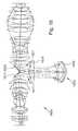
- FIG. 2shows a schematic illustration of the design of preferred embodiments of projection objectives according to the invention, with a refractive first objective part, a catadioptric second objective part, and a refractive third objective part;
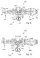
- FIG. 3shows a lens section through a first embodiment of a projection objective according to the invention
- FIG. 4shows a lens section through a second embodiment of a projection objective according to the invention
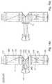
- FIG. 5shows a schematic illustration of the design of one embodiment of a projection objective according to the invention, with a different folding geometry and a crossed beam path;
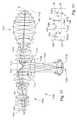
- FIG. 6shows a schematic illustration of one embodiment of a projection objective according to the invention, with a catadioptric first objective part, a catadioptric second objective part and a refractive third objective part;
- FIG. 7shows a lens section for one embodiment of a catadioptric first objective part with a physical beam splitter, which can be used for the design shown in FIG. 6 ;
- FIG. 8shows various mirror arrangements for folding mirrors for projection objectives according to the invention.
- FIG. 9shows a lens section for an embodiment having coaxial first and third objective parts
- FIG. 10shows a lens section for another embodiment having coaxial first and third objective parts
- FIG. 11shows a lens section through an embodiment having laterally offset first and third objective parts such that there is no object-image-shift (OIS), where FIG. 11 ′ illustrates the conditions therefore;
- OISobject-image-shift
- FIG. 12shows a lens section through a reference system having no field lens
- FIG. 13shows a lens section through an embodiment having an essentially telecentric chief ray at the folding mirrors
- FIG. 14shows schematic drawings illustrating the trajectories of the chief ray in a conventional system (a) and according to embodiments having an essentially telecentric chief ray at the folding mirrors (b);
- FIG. 15shows a lens section through another embodiment having essentially telecentric chief rays at the folding mirrors and a field lens geometrically close to the folding mirrors, where the field lens is optically situated both in the first objective part and in the third objective part;
- optical axismeans a straight line or a sequence of straight line sections through the centers of curvature of the optical components.
- the optical axisis folded on folding mirrors (deflection mirrors) or on other reflective surfaces. Directions and distances are described as being on the “image side” when they are directed in the direction of the image plane or of the substrate which is located there and is to be exposed, and as on the “object side” when they are directed toward the object plane or toward a reticle located there, with respect to the optical axis.
- the object in the examplesis a mask (reticle) with the pattern of an integrated circuit, although it may also be a different pattern, for example a grating.
- the image in the examplesis projected onto a wafer which is provided with a photoresist layer and is used as a substrate.
- Other substratesfor example elements for liquid crystal displays or substrates for optical gratings, are also possible.
- FIG. 1shows, schematically, a microlithographic projection exposure system in the form of a wafer stepper 1 , which is intended for production of large-scale integrated semiconductor components by means of immersion lithography.
- the projection exposure system 1has an excimer laser 2 as the light source, with an operating wavelength of 193 nm, although other operating wavelengths, for example 157 nm or 248 nm, are also possible.
- a downstream illumination system 3produces a large, sharply constricted, highly homogeneously illuminated illumination field, which is matched to the telecentric requirements of the downstream projection objective 5 on its exit plane 4 .
- the illumination system 3has devices for selection of the illumination mode and, in the example, can be switched between conventional illumination with a variable coherence degree, annular field illumination and dipole or quadrupole illumination.
- a device 40for holding and manipulating a mask 6 is arranged behind the illumination system in such a way that it is located on the object plane 4 of the projection objective 5 , and can be moved in a departure direction 7 (y direction) on this plane, for scanning purposes.
- the plane 4which is also referred to as the mask plane, is followed by the catadioptric reduction objective 5 , which images an image of the mask on a reduced scale of 4:1 on a wafer 10 which is covered with a photoresist layer.
- Other reduction scalesfor example 5:1, 10:1 or 100:1 or more, are likewise possible.
- the wafer 10which is used as a light-sensitive substrate, is arranged such that the planar substrate surface 11 together with the photoresist layer essentially coincides with the image plane 12 of the projection objective 5 .
- the waferis held by a device 50 (wafer stage) which comprises a scanner drive in order to move the wafer synchronously with the mask 6 and parallel to it.
- the device 50also has manipulators, in order to move the wafer both in the z direction parallel to the optical axis 13 of the projection objective and in the x and y directions at right angles to this axis.
- a tilting deviceis integrated, and has at least one tilting axis which runs at right angles to the optical axis 13 .
- the device 50which is provided for holding the wafer 10 , is designed for use for immersion lithography. It has a holding device 15 , which can be moved by a scanner drive and whose base has a flat depression or recess for holding the wafer 10 .
- a flat liquid-tight holder, which is open at the top, for a liquid immersion medium 20is formed by a circumferential rim 16 , and the immersion medium 20 can be introduced into the holder, and can be carried away from it, by devices that are not shown.
- the height of the rimis designed such that the filled immersion medium completely covers the surface 11 of the wafer 10 , and the exit-side end area 30 of the projection objective 5 can be immersed in the immersion liquid between the objective exit and the wafer surface while the working distance is set correctly.
- the entire systemis controlled by a central computer unit 60 .
- FIG. 2schematically illustrates one preferred embodiment of projection objectives according to the invention.
- the projection objective 200is used to image a pattern (which is arranged on its object plane 201 ) of a mask on a reduced scale on its image plane 202 , which is aligned parallel to the object plane, on a reduced scale. It has a first, refractive objective part 210 , which images the object field to form a first, real intermediate image 211 , a second, catadioptric objective part 220 , which images the first intermediate image to form a second real intermediate image 221 , and a third, refractive objective part 230 , which images the second intermediate image on a reduced scale on the image plane 202 .
- the catadioptric objective part 220has a concave mirror 225 .
- a first folding mirror 213is arranged in the vicinity of the first intermediate image, at an angle of 45° to the optical axis 204 , such that it reflects the radiation coming from the object plane in the direction of the concave mirror 225 .
- a second folding mirror 223whose planar mirror surface is aligned at right angles to the planar mirror surface of the first folding mirror, reflects the radiation coming from the concave mirror 225 in the direction of the image plane 202 .
- the folding mirrors 213 , 223are each located in the optical vicinity of the intermediate images, so that the light conductance value can be kept low.
- the intermediate imagesthat is the entire region between the paraxial intermediate image and the marginal ray intermediate image, are preferably not located on the mirror surfaces, thus resulting in a finite minimum distance between the intermediate image and the mirror surface, so that any faults in the mirror surface, for example scratches or impurities, are not imaged sharply on the image plane.
- the minimum distanceshould be set such that sub-apertures of the radiation, that is to say footprints of beams which originate from a specific field point or converge on it do not have a diameter of less than 5 mm, or 10 mm, on the mirror surface.
- Embodimentsexist in which both the first intermediate image 211 , that is to say the second intermediate image 221 as well, are located in the geometric space between the folding mirrors and the concave mirror 225 (solid arrows).
- This side armis also referred to as the horizontal arm (HOA).
- the first intermediate image 211 ′may be located in the beam path upstream of the first folding mirror 213
- the second intermediate image 221 ′may be located in the beam path downstream from the second folding mirror (arrows represented by dashed lines).
- the folding angles in this exemplary embodimentare exactly 90°. This is advantageous for the performance of the mirror layers of the folding mirrors. Deflections by more or less than 90° are also possible, thus resulting in an obliquely positioned horizontal arm.
- All of the objective parts 210 , 220 , 230have a positive refractive power.
- lenses or lens groups with a positive refractive powerare represented by double-headed arrows with points pointing outwards, while lenses or lens groups with a negative refractive power are, in contrast, represented by double-headed arrows with heads pointing inwards.
- the first objective part 210comprises two lens groups 215 , 216 with a positive refractive power, between which a possible diaphragm position exists where the chief ray 203 , which is shown by a solid line, intersects the optical axis 204 , which is shown by a dashed-dotted line.
- the optical axisis folded through 90° at the first folding mirror 213 .
- the first intermediate image 211is produced in the light path immediately downstream from the first folding mirror 213 .
- the first intermediate image 211acts as an object for the subsequent catadioptric objective part 220 .
- Thishas a positive lens group 226 close to the field, a negative lens group 227 close to the diaphragm, and the concave mirror 225 which is arranged immediately downstream from this and images the first intermediate image to form the second intermediate image 221 .
- the lens group 226which has a positive effect overall, is used as a “field lens” and is formed by a single positive lens, whose effect can also be produced, however, by two or more individual lenses with a positive refractive power overall.
- the negative lens group 227comprises one or more lenses with a negative effect.
- the second intermediate image 221which is located optically immediately in front of the second folding mirror 223 , is imaged by the third refractive objective part 230 on the image plane 202 .
- the refractive objective part 230has a first positive lens group 235 , a second negative lens group 236 , a third positive lens group 237 and a fourth positive lens group 238 . There is a possible diaphragm position between the positive lens groups 237 , 238 , where the chief ray intercepts the optical axis.
- FIG. 3shows a lens section through a projection objective 300 which is essentially formed using the principles explained with reference to FIG. 2 .
- Identical or corresponding elements or element groupsare annotated with the same reference symbols as in FIG. 2 , increased by 100.
- a biconvex positive lens 326through which the beam passes in two opposite directions, is provided geometrically between the folding mirrors 313 , 323 and the concave mirror 325 in a region of the projection objective through which the beam passes twice, with the beam passing through it both in the light path between the first intermediate image 311 and the concave mirror 325 and in the light path between the concave mirror and the second intermediate image 321 , or the image plane 302 , in mutually offset lens areas.
- the positive lens 326is arranged closer to the folding mirrors 313 , 323 than to the concave mirror 325 , in particular in the first third of the axial distance between the folding mirrors and the concave mirror.
- the marginal ray heightis small in comparison to the chief ray height, with the ratio of the marginal ray height to the chief ray height being approximately 0.3.
- the positive lens 326is thus arranged close to the field both with respect to the first intermediate image 311 and with respect to the second intermediate image 321 , and thus acts as a field lens for both intermediate images.
- the positive refractive power in the light path between the first intermediate image 311 and the concave mirror 325ensures, inter alia, that the diameters of the subsequent lenses 327 and of the concave mirror 325 can be kept small.
- the positive lenscan be moved very close to the two intermediate images when required, without being impeded by the folding mirrors, so that a strong correction effect is possible.
- the positive refractive power which is arranged close to the fieldallows the horizontal arm to be longer. Because of the large aperture in the first intermediate image 311 , the length of the horizontal arm would normally be shortened, so that the diameter of the concave mirror 325 and of the negative meniscus lenses in the negative group 327 which are arranged immediately upstream of it is linked to the color correction and should therefore not be indefinitely large.
- the inclusion of a positive lens group 326 close to the fieldalso increases the refractive power of the negative lenses 327 , owing to the compensation for the Petzval curvature (in comparison to the concave mirror), and thus increases the correction of the color longitudinal error for relatively small diameters in the area of the concave mirror.
- the catadioptric objective partcan thus be designed to be compact and with relatively small lens dimensions, with adequate color correction.
- the field lens 326which is arranged in the immediate vicinity of two intermediate images 311 , 321 also has major advantages with respect to optical correction, as will be explained in more detail in the following text.
- the reason for thisis as follows: at a long distance from the intermediate image, for example in the vicinity of the system diaphragm or its conjugate planes, all of the opening rays in a light beam have a finite and monotonally rising height with the pupil coordinate, that is to say an optical surface acts on all the opening rays. Opening beams which are located further outwards at the pupil edge also have an increasingly greater height on this surface (or more correctly: an increasing distance from the chief ray).
- the convex lens surface of the positive lens 326 which faces the intermediate images 311 , 321 and is arranged in their immediate proximityis aspherically curved. In conjunction with the arrangement close to the field, this allows a very major corrective effect to be achieved.
- At least the two to three lenses closest to the imagecan be manufactured from calcium fluoride, in order to avoid compaction problems.
- the crystallographic major axes of the lensescan be rotated with respect to one another.
- the concave mirror 325may also be in the form of an active mirror, in which the shape of the mirror surface can be varied by means of suitable manipulators. This can be used to compensate for various imaging errors.
- the beam path in the vicinity of at least one of the intermediate imagesis virtually telecentric.
- Table 1shows the specification of the design in tabular form. It should be noted, as an aside, that commas are used in lieu of decimals in some of the Tables set forth below.
- column 1shows the number of the surface which is refractive, reflective or is distinguished in some other way
- column 2shows the radius r of the surface (in mm)
- column 3shows the distance d between the surface and the subsequent surface (in mm)
- column 4shows the material of a component
- column 5shows the optically useable free diameters of the optical components (in mm). Reflective surfaces are annotated by “R” in column 1.
- the reciprocal (1/r) of the radiusindicates the surface curvature at the surface apex
- hindicates the distance between the surface point and the optical axis.
- the arrow heightis thus p(h), that is to say the distance between the surface point and the surface apex in the z direction, that is to say in the direction of the optical axis.
- the constants K, C1, C2, etc.are shown in Table 2.
- the image-side numerical aperture NAis 1.2, and the imaging scale reduction factor is 4:1.
- the systemis designed for an image field whose size is 26 ⁇ 5.0 mm 2 , and it is double telecentric.
- FIG. 4shows a lens section through a projection objective 400 which represents a variant of the embodiment shown in FIG. 3 and is likewise formed using the principles explained with reference to FIG. 2 .
- Identical or corresponding elements or element groupsare annotated with the same reference symbols as in FIG. 3 , increased by 100.
- the specifications for this exemplary embodimentare shown in Tables 3 and 4.
- a biconvex positive lens 426which is used as a field lens is arranged in the horizontal arm in the immediate optical vicinity of the intermediate images 411 , 421 which are arranged between the folding mirrors 413 , 423 and the concave mirror 425 , thus resulting in the horizontal arm having small dimensions and on the other hand in a major corrective effect to the intermediate images.
- a further special feature of this embodimentis the design of the third, refractive objective part 430 , which has a particularly compact configuration, with small dimensions and a small maximum diameter.
- the basic designwith an initial positive group 435 , followed by the negative group 436 and two subsequent positive groups 437 , 438 with an aperture diaphragm (aperture stop) A in between corresponds to the design shown in FIG. 3 .
- the entry surface E of the third lens group 437is located behind the biconcave negative lens 436 , which is the only lens in the second lens group 436 , in the area of maximum divergence of the beam diameter and in the area of a point of inflection of the marginal ray height.
- “Relatively large beam diameter” for the purposes of this applicationoccur in particular when the marginal ray height on a lens is at least as large as half the marginal ray height at a potential diaphragm position, for example at the system diaphragm. This measure takes account of the fact that the scattering effect of a negative lens may admittedly be desirable for correction reasons, but that any scattering effect downstream from the negative lens has a tendency to lead to larger lens diameters than will be necessary in the absence of a negative lens.
- the rays of the beamare joined together in the direction of the downstream image plane, and positive refractive power is required for this purpose.
- the positive lenses which are required for this purposemay overall be designed relatively moderately provided that there is also no need to compensate for the scattering effect of negative lenses in the combination of the beams. Furthermore, the number of lenses may be limited. The invention thus allows compact projection objectives with minimal lens dimensions.
- FIG. 5shows one embodiment of a projection objective 500 which, from the optical point of view, is designed on the basis of the principles explained with reference to FIG. 2 .
- Identical or corresponding elements or element groupsare annotated with the same reference symbols as in FIG. 2 , increased by 300.
- a comparison between the beam profiles in the systems shown in FIG. 2 and FIG. 5shows that different beam paths are possible within the scope of the invention.
- An uncrossed beam pathis shown in the system in FIG. 2 , since a first beam section which runs from the object plane to the concave mirror 225 and a second beam section which runs from this concave mirror to the image plane do not intersect anywhere.
- the embodiment shown in FIG. 5in contrast, has a crossed-over beam path.
- the first folding mirror 513is arranged on the side of the optical axis 504 facing away from the second folding mirror 523 , with the second folding mirror being geometrically located closer to the object plane.
- a first beam section 540 which runs from the object plane 501 to the concave mirror 525 and a second beam section 550 which runs from the concave mirror 525 via the second folding mirror 523 to the image planecross over in the region immediately upstream of the mirror surface of the second folding mirror 523 , in the vicinity of the intermediate images 511 , 521 .
- the second intermediate image 521is located optically immediately before the second folding mirror 523 , and geometrically in the vicinity of an inner mirror edge 528 , which faces the optical axis 504 , of the first folding mirror.
- This crossed beam pathin which the radiation is “forced by” the first folding mirror without any vignetting in the direction of the second folding mirror, in the region of the inner mirror edge 528 , allows optimization of the light conductance value of the system. It also provides more physical space for the two folding mirrors.
- the positive field lens group 526is located in the optical vicinity of both intermediate images, geometrically between the folding mirrors and the concave mirror, although the second folding mirror and the second intermediate image are somewhat further away from the positive lens 526 .
- a projection objective 600in which a pattern which is arranged on its object plane 601 is imaged on an image plane 602 aligned parallel to the object plane, generating two real intermediate images 611 , 621 .
- the projection objectivehas a first, catadioptric objective part 610 which produces a first real intermediate image 611 of the object field, a subsequent, catadioptric second objective part 620 , which images the first intermediate image to form a second real intermediate image 621 , and a subsequent third, refractive objective part, which images the second intermediate image 621 directly, that is to say without any further intermediate image, on the image plane 602 .
- the first objective part 610is a compact catadioptric subsystem.
- the catadioptric objective part 610has a concave mirror 615 whose optical axis is at right angles to the object plane, and a polarization-selective beam splitter 660 (Beamsplitter Cube, BSC) which is arranged between the object plane and the concave mirror and has a planar beam splitter surface 613 which is inclined at 45° to the optical axis 604 and is used as a first folding mirror for the projection objective 610 .
- BSCpolarization-selective beam splitter 660
- a ⁇ /4 plate 661 , a first positive group 662 , a second positive group 663 , the beam splitter 660 , a further ⁇ /4 plate 664 and a negative group 665 arranged immediately in front of the concave mirrorare arranged in this sequence between the object plane and the concave mirror. This is followed by a further ⁇ /4 plate 666 and a positive group 667 in the beam path downstream from the folding mirror 613 .
- the basic configuration of the second, catadioptric objective part 620 with a positive group 626 close to the fieldcorresponds essentially to the basic design shown in FIG. 2 .
- the third, refractive objective parthas only positive groups between which a diaphragm position is located.
- foldingthus takes place within the first, catadioptric objective part, with positive refractive power in the form of at least one positive lens 667 being arranged between the folding mirror 613 , which is responsible for this, and the first intermediate image 611 , which is produced by the first subsystem.
- the overall systemis operated with circularly polarized input light, which is converted by the first ⁇ /4 plate to linear-polarized radiation, which is p-polarized with respect to the obliquely positioned beam splitter layer 613 and thus essentially completely passes through it to the concave mirror 650 .
- the ⁇ /4 plate which is arranged between the beam splitter layer and the concave mirroris passed through twice by the linear-polarized radiation and in the process rotates the polarization preferred direction through 90° such that the radiation arriving from the concave mirror at the polarization splitter layer 613 is s-polarized with respect to this, and is reflected in the direction of the subsequent objective parts.
- the third ⁇ /4 plate 666converts the radiation to circularly polarized radiation, which then passes through the subsequent subsystems.
- catadioptric objective part 610can be designed such that, in conjunction with the mirror curvature and the negative refractive power upstream of the mirror, it can largely or completely correct both the image field curvature and the chromatic longitudinal aberration, the subsequent partial objectives are not loaded, or are only slightly loaded, by these imaging errors. Furthermore, this arrangement allows the physical space between the object plane and the horizontally aligned, catadioptric objective part 620 to be enlarged, which can be used in order to reduce the light conductance value.
- the aperture diaphragm Ais preferably arranged in the third objective part 630 , which is closest to the image, where the chief ray intersects the optical axis. Two further possible diaphragm positions are shown in the first and second objective part, in each case close to the concave mirrors 615 , 625 .
- the first objective partmay be physically compact.
- FIG. 7shows an embodiment of a catadioptric subsystem which can be used as the first objective part 610 for the system shown in FIG. 6 , and whose specification is shown in Table 5. Identical or corresponding elements or element groups are annotated with the same reference symbols as in FIG. 6 , increased by 100. All the lenses are spherical, and all the transparent components including the beam splitter block 760 are composed of synthetic quartz glass.
- FIG. 8shows various implementation options, schematically, for the folding mirrors which are provided for folding the beam path.
- the folding mirrorsmay, for example, be in the form of free-standing planar mirrors, in particular as front surface mirrors ( FIGS. 8( a ) and ( b )). In this case, in the embodiments shown in FIG. 2 , separate mirrors as shown in FIG. 8( b ) can be held jointly, as well.
- the folding mirrorsmay also be in the form of free-standing prisms, as shown in FIGS. 8( c ) and ( d ).
- the reflective prism surfacesmay, if required, act as total internal reflection surfaces depending on the incidence angles that occur on them, or may have a reflection coating.
- the mirrorsmay also be in the form of reflective outer surfaces of a mirror prism as shown in FIG. 8( e ).
- FIG. 9a further embodiment of a projection objective 900 having R-C-R-type as explained in connection with FIG. 2 is shown.
- a first, refractive objective part 910is designed to image an off-axis effective object field OF arranged in the object surface 901 onto a first intermediate image 911 .
- a first planar folding mirror 913is arranged within the first objective part immediately upstream of the first intermediate image.
- a second, catadioptric objective part 920 including a concave mirror 925is designed for imaging the first intermediate image into a second intermediate image 921 positioned immediately upstream of a second folding mirror 923 at a distance therefrom.
- a third, refractive objective part 930 including a freely accessible aperture stop ASis designed to image the second intermediate image onto the image surface 902 , where an effective image field IF arranged outside the optical axis is created.
- the first objective part 910serves as a relay system to place the first intermediate image close to the first folding mirror 913 .
- the catadioptric second objective part 920includes a single positive lens (field lens 926 ) geometrically close to the folding mirrors and optically close to both intermediate images, thereby allowing efficient correction of field related imaging errors.
- the overall track length(axial distance between object surface 901 and image surface 902 ) is 1400 mm.
- the wavefront aberrationis about 4 m ⁇ rms.
- the specificationis given in tables 9, 9A.
- the chief ray CR of the imagingis drawn bold to facilitate following trajectory of the chief ray.
- the lenses of the first objective part 910define a first part OA 1 of the optical axis, which is the axis of rotational symmetry of the lenses and is perpendicular to the object surface 901 .
- the axis of rotational symmetry of the concave mirror 925 and the lenses of the second objective partdefine a second part OA 2 of the optical axis which, in this embodiment, is aligned perpendicular to the object side first part OA 1 of the optical axis.
- the optical axisis folded by the first folding mirror 913 at 90°.
- the lenses of the third objective part 930define a third part OA 3 of the optical axis, which is parallel to the first part OA 1 of the optical axis and perpendicular to the image surface 902 .
- the object-side first part OA 1 of the optical axis and the image-side third part OA 3 of the optical axisare coaxial such that no lateral axis offset exists between these parts of the optical axis.
- This constructionmay be desirable with regard to mounting of the lenses of the refractive objective parts.
- a similar construction with coaxial first and third parts OA 1 , OA 3 of the optical axisis shown as projection objective 1000 in FIG. 10 .
- the specification of that designis given in table 10, 10A. In both embodiments a finite value for the object-image-shift OIS exists.
- the lens surface ASP immediately upstream of the first folding mirror 913is an aspheric surface, which is optically close to the first intermediate image. Efficient correction of field related imaging errors are obtained.
- the field lens 1026has an aspheric lens surface ASP facing the concave mirror. This aspheric surface is the lens surface closest to both the first and second intermediate image 1011 , 1021 and therefore very effective for correction at two positions along the beam path.
- the wave front aberration of this designis about 3 m ⁇ rms.
- FIG. 11The embodiment of a projection objective 1100 shown in FIG. 11 (specification in tables 11, 11A) is an example to demonstrate that practical advantages can be obtained in preferred embodiments if a lateral axis offset AO between the first part OA 1 of the optical axis on the object side and a third part OA 3 of the optical axis on the image side is adjusted appropriately.
- FIG. 11 ′shows a schematic drawing where important features and parameters are shown.
- an off-axis effective object field OFis imaged by the first objective part 1110 into a first intermediate image 1111 arranged between a first folding mirror 1113 and a positive field lens 1126 of the second objective part 1120 .
- the second objective partincludes the concave mirror 1125 and is designed as an imaging subsystem to create a second intermediate image 1121 positioned between positive lens 1126 and a second folding mirror 1123 .
- the folding prism forming with perpendicular planar faces the first and second folding mirrorsis used asymmetrically, whereby a lateral axis offset AO is obtained between the first part OA 1 of the optical axis on the object side and the third part OA 3 of the optical axis on the image side (see FIG. 11 ′).
- the axis offset AOis set in such a way that an object field center axis OFCA running parallel to the first part OA 1 of the optical axis through the object field center and an image field center axis IFCA running through the center of the image field IF and parallel to the third part OA 3 of the optical axis coincide (are coaxial).
- object-image-shift(OIS) between the centers of the effective object field OF and image field IF.
- This propertyis usually not obtained in catadioptric projection objectives with off-axis object field, but only in projection objectives having an effective object field centered around the optical axis (e.g. purely refractive objectives or catadioptric objectives having a physical beam splitter or objectives with pupil obscuration).
- schematic FIG. 14shows a prior art system without field lens in (a) and an embodiment of the invention including a field lens FL in (b). The trajectory of a chief ray CR is drawn and bold in FIGS. 12 and 13 and also outlined in FIG. 14 where, in addition, the trajectory of a marginal ray MR is shown.
- the first objective partis a refractive relay group L 1 designed to create the first intermediate image IMI 1 close to the first folding mirror FM 1 of the folding prism.
- An axially compact (short) catadioptric second objective part including the concave mirror CMcreates the second intermediate image IMI 2 close to the second folding mirror FM 2 .
- a purely refractive main focussing group L 2 formed by the third objective partforms the image.
- the first objective partis subdivided into a first lens group LG 1 and a second lens group LG 2 (each positive refractive power), a pupil surface being positioned between these lens groups where the chief ray CR intersects the optical axis OA.
- the third objective partincludes, in that sequence, a third lens group LG 3 with positive refractive power, a fourth lens group LG 4 with negative refractive power, and a fifth lens group LG 5 with positive refractive power.
- An image side pupil surfaceis positioned in the third objective part where the chief ray crosses the optical axis.
- An aperture stop ASis usually positioned at this position.
- a pupil surface optically between the first and second intermediate imageis positioned close to or at the concave mirror CM.
- an aperture stopmay also be positioned in one of the other pupil surfaces, namely in the refractive relay group L 1 or in the catadioptric group, close to the concave mirror.
- the chief ray CRis convergent at the first intermediate image IMI 1 and the first folding mirror optically close to that intermediate image.
- a convergent chief rayis a chief ray where the chief ray height CRH, i.e. the radial distance between the chief ray and the optical axis, is decreasing in light propagation direction.
- the chief rayis divergent (i.e. chief ray height increasing in light propagation direction) at the second intermediate image IMI 2 and the second folding mirror.
- the lenses of the second lens group LG 2 and the third lens group LG 3 closest to the first intermediate image and the second intermediate image, respectively,are optically relatively far away from the intermediate images since the folding mirror is placed between these lenses and the intermediate images.
- these lenses closest to the folding mirrorshave a tendency to become large (large lens diameter). Note that this effect may be weaker if a larger distance is set between the concave mirror and the folding mirrors, thereby forming a longer horizontal arm (HOA) of the objective.
- HOAhorizontal arm
- the concave mirroris to correct the Petzvalsum (image field curvature) of the projection objective.
- the contribution of the concave mirror for Petzval sum correctionis directly proportional to the curvature of the concave mirror. If the numerical aperture of the system is to be increased and, at the same time, the length of the horizontal arm HOA would remain constant, the diameter of the catadioptric group including the concave mirror would be increased.
- the curvature of the concave mirrorwould become smaller, whereby the effect of the concave mirror on Petzval sum correction would decrease. This is considered less desirable since the Petzval sum correction must then be provided in other parts of the projection objective, thereby making the design more complicated.
- the diameter of the catadioptric group including the concave mirrorshould be maintained essentially constant. This, however, corresponds to a decreasing length of the horizontal arm which, in turn, leads to relatively large chief ray angles at the intermediate images, as shown schematically in FIG. 14( a ) and in the projection objective 1200 of FIG. 12 .
- the first objective part(relay group L 1 ) axially shorter and to decrease the diameters of the lenses immediately upstream of the first folding mirror.
- a field lens having sufficient positive refractive power geometrically between the folding mirrors and the concave mirror optically close to the intermediate imagesas shown schematically in FIG. 14( b ) and exemplarily in embodiment 1300 of FIG. 13 .
- the positive refractive power provided by a lens 1326allows to guide the chief ray CR almost parallel to the optical axis or slightly divergent onto the first folding mirror 1313 , whereby the diameters of the two or three lenses immediately upstream of the first folding mirror can be substantially reduced when compared to the design of FIG. 12 .
- the first axial length AL 1 of the first objective part 1310is substantially reduced when compared to the corresponding length of the first objective part 1210 in FIG. 12 .
- more spaceis available in the third objective part for introducing lenses contributing to an increase in numerical aperture.
- the horizontal arm including the concave mirroris substantially longer and the concave mirror is substantially smaller when a field lens is introduced.
- both the first and second intermediate imageare positioned in a space between the field lens 1326 and the mirror group including the concave mirror 1325 .
- an axial distance between the intermediate images and the closest optical surfaceis sufficiently large such that the closest optical surface lies outside an intermediate image space defined axially between the paraxial intermediate image (intermediate image formed by paraxial rays) and the marginal ray intermediate image (formed by marginal rays of the imaging).
- a minimum distance of at least 10 mmis obtained here.
- the field lensis effective as a last lens of the first objective part 1310 and as a first lens of the third objective part 1330 (when viewed in light propagation direction at the intended use as reduction projection objective). Therefore, it is worth to note that FIG. 13 shows a projection objective having two refractive imaging subsystems (formed by the first objective part 1310 and the third objective part 1330 ), where a lens (the field lens 1326 ) is arranged optically within both the first and the third imaging subsystem. Also, each folding mirror is positioned inside a refractive imaging subsystem between lenses of the respective subsystem.
- FIGS. 15 to 17are based on the embodiment of FIG. 13 and show exemplarily that a basic design having a field lens with sufficient refractive power allows to obtain even higher image side numerical apertures with moderate lens sizes.
- the specificationsare given in tables 15, 15A, 16, 16A and 17, 17A, respectively.
- the chief ray CRis almost parallel to the optical axis at the first and second folding mirror.
- the positive field lens 1326 , 1526 in the horizontal armis arranged very close to the folding mirrors such that intermediate images follow within a space free of optical material between that field lens and the concave mirror.
- one or more truncated lensesmust be used close to the folding mirrors, which makes lens mounting more complicated.
- Such mounting problemis avoided for the projection objective 1600 in FIG. 16 , where the positive field lens 1626 is positioned far away from the folding mirrors 1613 , 1623 mostly outside a cylindrical space defined between the lenses immediately upstream and downstream of the folding mirrors.
- circular lenses with a stable mounting techniquecan be used. From an optical point of view, the chief ray angles at the first and second folding mirrors are almost zero (essentially telecentric chief ray).
- the field lensis now part of the catadioptric second imaging objective part 1620 including the concave mirror 1625 .
- the chief rayis almost telecentric at the folding mirrors and the intermediate images 1711 , 1721 are essentially positioned between the folding mirrors and the field lens 1726 .
- the increase in numerical aperture with respect to the embodiment of FIG. 16shows that in that embodiment sufficient space for further and/or stronger lenses is available in the third objective part responsible for providing the high numerical aperture.
- the inventionallows to built catadioptric projection objectives with high numerical aperture, particularly allowing immersion lithography at numerical apertures NA>1, that can be built with relatively small amounts of optical material.
- the potential for small material consumptionis demonstrated in the following considering parameters describing the fact that particularly compact projection objectives can be manufactured.
- the first compaction parameter COMP1should be as small as possible if a compact design is desired.
- projection objectiveshave at least three objective parts for imaging an entry side field surface into an optically conjugate exit side field surface, where the imaging objective parts are concatenated at intermediate images.
- Table 18summarizes the values necessary to calculate the compactness parameters COMP1, COMP2, COMP3 and the respective values for these parameters for each of the systems presented with a specification table (the table number (corresponding to the same number of a figure) is given in column 1 of table 18). Therefore, in order to obtain a compact catadioptric projection objective having at least one concave mirror and at least two imaging objective parts (i.e. at least one intermediate image) at least one of the following conditions (1) to (3) should be observed: COMP1 ⁇ 11 (1)
- COMP1 ⁇ 10.7Preferably COMP1 ⁇ 10.7 should be observed.
- COMP2 ⁇ 320Preferably COMP2 ⁇ 320, more preferably COMP2 ⁇ 300 should be observed.
- COMP3 ⁇ 100Preferably COMP3 ⁇ 100 should be observed.
- COMP1 ⁇ 11 and, at the same time, COMP2 ⁇ 340which allows particularly compact designs.
- the concave mirrorhas a mirror diameter D M
- the projection objectivehas a maximum lens diameter D max
- the condition D M ⁇ 0.75*D maxholds.
- D M ⁇ 0.70*D maxmay be fulfilled.
- Table 18shows that preferred embodiments according to the invention generally observe at least one of these conditions indicating that compact designs with moderate material consumption and/or small concave mirror are obtained according to the design rules laid out in this specification.
- R-C-R type catadioptric projection objectiveshaving a first folding mirror for deflecting the radiation coming from the object plane in the direction of the concave mirror and a second folding mirror for deflecting the radiation coming from the concave mirror in the direction of the image plane.
- the inventioncan also be implemented in designs having different folding geometry, for example those where radiation coming from the object plane is directly directed at the concave mirror prior to a reflection on a first folding mirror arranged for deflecting the radiation coming from the concave mirror in the direction of the image plane.
- a second folding mirroris usually provided downstream of the first folding mirror to allow a parallel arrangement of object plane and image plane.
- all of the systems described abovemay be complete systems, that is to say systems for forming a real image (for example on a wafer) of a real object (for example a photolithography mask).
- the systemsmay, however, also be used as subsystems for larger systems.
- the “object” of one of the systems described abovemay thus be an image which is produced by an imaging system (for example a relay system) positioned upstream of the object plane.
- An image which is formed by one of the systems described abovemay likewise be used as an object for a system (for example a relay system) downstream from the image plane.
- the enumeration of the objective partswith the expressions “first objective part” and “second objective part” etc.
- first and secondshould be understood as being relative to one another.
- the “first” objective partis arranged upstream of the “second” objective part in the direction in which the beam passes through them. This need not necessarily be the first objective part in the overall system, that is to say the objective part which immediately follows the image plane in the system. However, this is the case in the illustrated exemplary embodiments.
Landscapes
- Physics & Mathematics (AREA)
- General Physics & Mathematics (AREA)
- Optics & Photonics (AREA)
- Lenses (AREA)
- Exposure And Positioning Against Photoresist Photosensitive Materials (AREA)
- Exposure Of Semiconductors, Excluding Electron Or Ion Beam Exposure (AREA)
Abstract
Description
0≦OIS<|h·(1−|β|)|.
|CRA1|<|β1*(YOB)/(LHOA)|
where β1denotes the magnification of the first objective part, YOBis the object height of the outermost field point for which the chief ray is considered and LHOAis the geometrical distance from the first intermediate image to the concave mirror (length of the horizontal axis). With other words, it may be desirable that the chief ray is telecentric or almost telecentric at a an intermediate image. A chief ray obeying the condition given above will be denoted as an “essentially telecentric chief ray” in the following. Providing an essentially telecentric chief ray at a folding mirror close to such intermediate image allows to limit the size of lenses immediately upstream and/or downstream of the folding mirror. In addition, it has been found that installation space within the third objective part responsible for providing high image side numerical apertures is obtained.
p(h)=R[((1/r)h2/(1+SQRT(1−(1+K)(1/r)2h2))]+C1*h4+C2*h6+ . . . .
|AO|=|h*(1+|β|)|.
COMP1=Dmax/(Y′·NA2).
COMP2=COMP1·NL.
COMP3=COMP1·NL/NOP.
COMP1<11 (1)
COMP2<340 (2)
COMP3<110 (3)
| TABLE 1 | |||
| WL | 157.2852 | 157.2862 | 157.2842 |
| CAF2 | 1.55930394 | 1.55930133 | 1.55930655 |
| IMM | 1.37021435 | 1.37021206 | 1.37021665 |
| Surface | Radius | Distance | Material | ½ Diameter |
| 0 | 0.000000000 | 48.029632171 | AIR | 57.700 |
| 1 | 0.000000000 | 39.172776328 | AIR | 72.768 |
| 2 | −96.971407438 | 43.719958386 | CAF2 | 74.418 |
| 3 | −158.002766036 | 5.165244231 | AIR | 98.534 |
| 4 | 781.518257267 | 56.238731708 | CAF2 | 120.188 |
| 5 | −253.290501301 | 4.909571912 | AIR | 123.211 |
| 6 | 288.016848173 | 49.396794919 | CAF2 | 124.172 |
| 7 | −435.168087157 | 26.736905514 | AIR | 122.368 |
| 8 | 105.910945049 | 62.394238960 | CAF2 | 94.783 |
| 9 | 178.598362309 | 79.753912118 | AIR | 79.042 |
| 10 | −274.352911686 | 15.001130830 | CAF2 | 42.116 |
| 11 | −481.511902624 | 46.498544862 | AIR | 46.787 |
| 12 | −70.442117850 | 52.555341121 | CAF2 | 55.942 |
| 13 | −90.455727573 | 1.806830035 | AIR | 78.160 |
| 14 | 3232.255140950 | 36.176140320 | CAF2 | 91.116 |
| 15 | −186.488036306 | 1.000000000 | AIR | 92.734 |
| 16 | 365.731282758 | 20.809036457 | CAF2 | 90.268 |
| 17 | −2611.121142850 | 101.825417590 | AIR | 88.935 |
| 18 | 0.000000000 | 0.000000000 | AIR | 84.274 |
| 19 | 0.000000000 | 65.181628952 | AIR | 84.274 |
| 20 | 258.735107311 | 37.578859051 | CAF2 | 105.187 |
| 21 | −1152.159158690 | 288.921175238 | AIR | 104.969 |
| 22 | −129.279458408 | 15.003276235 | CAF2 | 81.991 |
| 23 | −2262.350961510 | 56.312694509 | AIR | 88.341 |
| 24 | −117.450410520 | 15.001009008 | CAF2 | 91.957 |
| 25 | −309.800170740 | 28.401147541 | AIR | 113.929 |
| 26 R | −175.988719829 | 0.000000000 | AIR | 117.602 |
| 27 R | 0.000000000 | 28.401147541 | AIR | 168.871 |
| 28 | 309.800170740 | 15.001009008 | CAF2 | 112.745 |
| 29 | 117.450410520 | 56.312694509 | AIR | 87.774 |
| 30 | 2262.350961510 | 15.003276235 | CAF2 | 78.116 |
| 31 | 129.279458408 | 288.921175238 | AIR | 70.315 |
| 32 | 1152.159158690 | 37.578859051 | CAF2 | 91.290 |
| 33 | −258.735107311 | 65.181629067 | AIR | 91.634 |
| 34 | 0.000000000 | 0.000000000 | AIR | 84.438 |
| 35 | 0.000000000 | 95.566202561 | AIR | 84.438 |
| 36 | −385.455042894 | 15.000000000 | CAF2 | 93.816 |
| 37 | −452.475904634 | 1.000000003 | AIR | 97.482 |
| 38 | 254.248242468 | 32.034900497 | CAF2 | 105.601 |
| 39 | 5899.473023640 | 1.000023801 | AIR | 105.353 |
| 40 | 190.848967014 | 30.278271846 | CAF2 | 104.456 |
| 41 | 621.351654529 | 138.920391104 | AIR | 102.039 |
| 42 | −123.640610032 | 33.881654714 | CAF2 | 76.579 |
| 43 | 158.155949669 | 49.867792861 | AIR | 80.512 |
| 44 | 412.757602921 | 47.829461944 | CAF2 | 98.825 |
| 45 | −208.949912656 | 17.094373280 | AIR | 103.896 |
| 46 | −158.641772839 | 15.212844332 | CAF2 | 105.038 |
| 47 | −313.678744542 | 1.052590482 | AIR | 118.827 |
| 48 | −829.528825093 | 55.527291516 | CAF2 | 125.550 |
| 49 | −184.492343437 | 11.796257723 | AIR | 129.573 |
| 50 | 260.696800337 | 37.374556186 | CAF2 | 132.314 |
| 51 | 497.808165974 | 65.844307831 | AIR | 127.088 |
| STO | 0.000000000 | 0.000000000 | AIR | 127.776 |
| 53 | 0.000000000 | −22.615444914 | AIR | 128.288 |
| 54 | 358.239917958 | 44.763751865 | CAF2 | 128.404 |
| 55 | −739.494996855 | 1.004833255 | AIR | 127.649 |
| 56 | 242.528908132 | 44.488018592 | CAF2 | 121.037 |
| 57 | 3949.584753010 | 1.000094237 | AIR | 116.970 |
| 58 | 201.527861764 | 58.711711773 | CAF2 | 103.897 |
| 59 | −1366.391075450 | 1.000007100 | AIR | 89.104 |
| 60 | 62.439639631 | 63.828426005 | CAF2 | 55.026 |
| 61 | 0.000000000 | 1.550000000 | IMM | 17.302 |
| 62 | 0.000000000 | 0.000000000 | AIR | 14.425 |
| NA = 1.2 | ||||
| Y = 57.7 mm | ||||
| TABLE 2 |
| Aspherical constant |
| Surface No. 2 |
| K | 0.0000 |
| C1 | 1.90827109e−008 |
| C2 | 1.04825601e−012 |
| C3 | −1.78093208e−017 |
| C4 | 2.90254732e−020 |
| C5 | −9.28646308e−025 |
| C6 | 9.92757252e−029 |
| C7 | 0.00000000e+000 |
| C8 | 0.00000000e+000 |
| C9 | 0.00000000e+000 |
| Surface No. 7 |
| K | 0.0000 |
| C1 | 4.29834963e−008 |
| C2 | −9.32018657e−013 |
| C3 | 3.88421097e−017 |
| C4 | −1.41048066e−021 |
| C5 | 3.20036532e−026 |
| C6 | −2.55377630e−031 |
| C7 | 0.00000000e+000 |
| C8 | 0.00000000e+000 |
| C9 | 0.00000000e+000 |
| Surfface No. 12 |
| K | 0.0000 |
| C1 | 7.12539594e−008 |
| C2 | 7.81169353e−012 |
| C3 | 2.24285994e−016 |
| C4 | 2.70399434e−019 |
| C5 | −5.336583256−023 |
| C6 | 1.078246756−026 |
| C7 | 0.00000000e+000 |
| C8 | 0.00000000e+000 |
| C9 | 0.00000000e+000 |
| Surface No. 17 |
| K | 0.0000 |
| C1 | 3.44530878e−008 |
| C2 | −3.20209778e−013 |
| C3 | 4.32090602e−018 |
| C4 | 3.71891782e−022 |
| C5 | −2.41461999e−026 |
| C6 | 6.86020285e−031 |
| C7 | 0.00000000e+000 |
| C8 | 0.00000000e+000 |
| C9 | 0.00000000e+000 |
| Surface No. 20 |
| K | 0.0000 |
| C1 | 5.99206839e−009 |
| C2 | −2.26778093e−013 |
| C3 | −5.52734742e−019 |
| C4 | 3.37919534e−022 |
| C5 | −2.42416300e−026 |
| C6 | 5.56746821e−031 |
| C7 | 0.00000000e+000 |
| C8 | 0.00000000e+000 |
| C9 | 0.00000000e+000 |
| Surface No. 22 |
| K | 0.0000 |
| C1 | 6.63814399e−008 |
| C2 | 1.50151781e−012 |
| C3 | 3.42715896e−017 |
| C4 | 1.13418489e−020 |
| C5 | −1.20800658e−024 |
| C6 | 1.36760067e−028 |
| C7 | 0.00000000e+000 |
| C8 | 0.00000000e+000 |
| C9 | 0.00000000e+000 |
| Surface No. 31 |
| K | 0.0000 |
| C1 | −6.63814399e−008 |
| C2 | −1.50151781e−012 |
| C3 | −3.42715896e−017 |
| C4 | −1.13418489e−020 |
| C5 | 1.20800658e−024 |
| C6 | −1.36760067e−028 |
| C7 | 0.00000000e+000 |
| C8 | 0.00000000e+000 |
| C9 | 0.00000000e+000 |
| Surface No. .33 |
| K | 0.0000 |
| C1 | −5.99206839e−009 |
| C2 | 2.26778093e−013 |
| C3 | 5.52734742e−019 |
| C4 | −3.37919534e−022 |
| C5 | 2.42416300e−026 |
| C6 | −5.56746821e−031 |
| C7 | 0.00000000e+000 |
| C8 | 0.00000000e+000 |
| C9 | 0.00000000e+000 |
| Surface No. 41 |
| K | 0.0000 |
| C1 | 3.02036913e−008 |
| C2 | −8.49897291e−013 |
| C3 | −2.62757380e−018 |
| C4 | 2.42290737e−021 |
| C5 | −1.803848866−025 |
| C6 | 4.40130958e−030 |
| C7 | 0.00000000e+000 |
| C8 | 0.00000000e+000 |
| C9 | 0.00000000e+000 |
| Surface No. 42 |
| K | 0.0000 |
| C1 | 1.57083344e−007 |
| C2 | −5.70047014e−012 |
| C3 | 9.96269363e−016 |
| C4 | −9.51074757e−020 |
| C5 | 2.78023503e−024 |
| C6 | 2.11268686e−028 |
| C7 | 0.00000000e+000 |
| C8 | 0.00000000e+000 |
| C9 | 0.00000000e+000 |
| Surface No. 44 |
| K | 0.0000 |
| C1 | −6.63114425e−008 |
| C2 | 1.06389778e−012 |
| C3 | −1.73700448e−016 |
| C4 | 7.83565903e−021 |
| C5 | −3.69851418e−025 |
| C6 | 6.43100123e−031 |
| C7 | 0.00000000e+000 |
| C8 | 0.00000000e+000 |
| C9 | 0.00000000e+000 |
| Surface No. 51 |
| K | 0.0000 |
| C1 | 3.97980700e−008 |
| C2 | −1.14363396e−015 |
| C3 | 2.121736276−019 |
| C4 | −1.811771436−022 |
| C5 | −9.65440963e−027 |
| C6 | 3.69511989e−031 |
| C7 | 0.00000000e+000 |
| C8 | 0.00000000e+000 |
| C9 | 0.00000000e+000 |
| Surface No. 59 |
| K | 0.0000 |
| C1 | 3.28933356e−008 |
| C2 | −4.67953085e−013 |
| C3 | 1.96156711e−017 |
| C4 | 1.01627452e−022 |
| C5 | −3.59201172e−026 |
| C6 | 2.16163436e−030 |
| C7 | 0.00000000e+000 |
| C8 | 0.00000000e+000 |
| C9 | 0.00000000e+000 |
| TABLE 3 | |||
| WL | 157.2852 | 157.2862 | 157.2842 |
| CAF2 | 1.55930394 | 1.55930133 | 1.55930655 |
| Surface | Radius | Distance | Material | ½ Diameter |
| 0 | 0.000000000 | 47.596241819 | AIR | 57.700 |
| 1 | 0.000000000 | 21.484078486 | AIR | 71.361 |
| 2 | −130.196528296 | 81.232017348 | CAF2 | 71.411 |
| 3 | −201.970612192 | 1.090292328 | AIR | 102.064 |
| 4 | 0.000000000 | 43.035190104 | CAF2 | 111.239 |
| 5 | −219.688636866 | 1.000008083 | AIR | 113.511 |
| 6 | 196.835177454 | 48.645753259 | CAF2 | 112.440 |
| 7 | −1062.563638620 | 1.011278327 | AIR | 109.626 |
| 8 | 102.486371771 | 51.257817769 | CAF2 | 88.766 |
| 9 | 125.152226832 | 78.537765316 | AIR | 72.052 |
| 10 | −276.036111675 | 19.246024827 | CAF2 | 35.565 |
| 11 | −344.559129459 | 44.417965355 | AIR | 42.153 |
| 12 | −73.158562407 | 46.803238343 | CAF2 | 53.934 |
| 13 | −81.595671547 | 1.005611042 | AIR | 71.774 |
| 14 | 917.859457951 | 35.862144308 | CAF2 | 83.802 |
| 15 | −184.688054893 | 1.002179985 | AIR | 85.191 |
| 16 | 520.342292054 | 23.034106261 | CAF2 | 82.478 |
| 17 | −768.099839930 | 99.999802859 | AIR | 80.816 |
| 18 | 0.000000000 | 0.000000000 | AIR | 72.928 |
| 19 | 0.000000000 | 49.999962118 | AIR | 72.928 |
| 20 | 241.487091044 | 30.190977973 | CAF2 | 85.575 |
| 21 | −1164.355916310 | 264.025266484 | AIR | 85.757 |
| 22 | −132.516232462 | 15.000193519 | CAF2 | 81.831 |
| 23 | −1356.484422410 | 61.385058143 | AIR | 89.265 |
| 24 | −108.588059874 | 14.999993604 | CAF2 | 92.698 |
| 25 | −296.429590341 | 28.045104017 | AIR | 119.543 |
| 26 R | −171.604551151 | 0.000000000 | AIR | 121.617 |
| 27 R | 0.000000000 | 28.045104017 | AIR | 187.566 |
| 28 | 296.429590341 | 14.999993604 | CAF2 | 118.640 |
| 29 | 108.588059874 | 61.385058143 | AIR | 87.692 |
| 30 | 1356.484422410 | 15.000193519 | CAF2 | 75.436 |
| 31 | 132.516232462 | 264.025266484 | AIR | 68.614 |
| 32 | 1164.355916310 | 30.190977973 | CAF2 | 79.925 |
| 33 | −241.487091044 | 49.999914356 | AIR | 79.985 |
| 34 | 0.000000000 | 0.000000000 | AIR | 73.069 |
| 35 | 0.000000000 | 107.612168038 | AIR | 73.069 |
| 36 | −693.184976623 | 16.117644573 | CAF2 | 81.276 |
| 37 | −696.986438150 | 2.228062889 | AIR | 84.557 |
| 38 | 272.001870523 | 26.851322582 | CAF2 | 90.453 |
| 39 | −11518.014964700 | 1.683452367 | AIR | 90.747 |
| 40 | 204.924277454 | 41.781211890 | CAF2 | 91.627 |
| 41 | 3033.528484830 | 106.582128113 | AIR | 88.228 |
| 42 | −134.400581416 | 22.683343530 | CAF2 | 70.595 |
| 43 | 149.085276952 | 30.111359058 | AIR | 72.323 |
| 44 | −1571.459281550 | 66.592767742 | CAF2 | 74.527 |
| 45 | −685.256687590 | 11.096249234 | AIR | 101.072 |
| 46 | −661.646567779 | 85.751986497 | CAF2 | 106.788 |
| 47 | −157.414472118 | 1.578582665 | AIR | 121.872 |
| 48 | 281.442061787 | 38.097581301 | CAF2 | 126.470 |
| 49 | 2477.671193110 | 77.916990124 | AIR | 123.978 |
| 50 | 0.000000000 | 0.000000000 | AIR | 117.805 |
| 51 | 0.000000000 | -4.224796803 | AIR | 118.082 |
| 52 | 629.850672554 | 48.195853438 | CAF2 | 118.380 |
| 53 | −440.009879814 | 0.999978780 | AIR | 118.034 |
| 54 | 243.613408298 | 52.262412712 | CAF2 | 109.822 |
| 55 | 11973.088705700 | 1.027491789 | AIR | 101.920 |
| 56 | 115.269169988 | 60.712228046 | CAF2 | 83.889 |
| 57 | 372.135519803 | 1.030688086 | AIR | 63.468 |
| 58 | 72.776794128 | 53.208894511 | CAF2 | 48.890 |
| 59 | 0.000000000 | 0.000000000 | CAF2 | 14.425 |
| 60 | 0.000000000 | 0.000000000 | AIR | 14.425 |
| NA = 1.1 | ||||
| Y = 57.7 mm | ||||
| TABLE 4 |
| Aspherical constants |
| Surface No. 2 |
| K | 0.0000 |
| C1 | −4.90420246e−011 |
| C2 | 7.22127484e−014 |
| C3 | 1.72996941e−017 |
| C4 | −3.83158229e−021 |
| C5 | 1.65903133e−024 |
| C6 | −1.68929866e−028 |
| C7 | 0.00000000e+000 |
| C8 | 0.00000000e+000 |
| C9 | 0.00000000e+000 |
| Surface No. 7 |
| K | 0.0000 |
| C1 | 2.96559302e−008 |
| C2 | −4.45892297e−013 |
| C3 | 1.35851832e−017 |
| C4 | −9.75107227e−022 |
| C5 | 6.40021152e−026 |
| C6 | −9.93085086e−031 |
| C7 | 0.00000000e+000 |
| C8 | 0.00000000e+000 |
| C9 | 0.00000000e+000 |
| Surface No. 12 |
| K | 0.0000 |
| C1 | 6.82301843e−008 |
| C2 | 6.13339976e−012 |
| C3 | −1.47536226e−016 |
| C4 | −7.56092252e−020 |
| C5 | 1.52586945e−023 |
| C6 | −1.35801785e−027 |
| C7 | 0.00000000e+000 |
| C8 | 0.00000000e+000 |
| C9 | 0.00000000e+000 |
| Surface No. 17 |
| K | 0.0000 |
| C1 | 4.47108229e−008 |
| C2 | −4.00171489e−013 |
| C3 | 4.13032418e−018 |
| C4 | 6.29956500e−022 |
| C5 | −3.85978221e−026 |
| C6 | 2.31708241e−030 |
| C7 | 0.00000000e+000 |
| C8 | 0.00000000e+000 |
| C9 | 0.00000000e+000 |
| Surface No. 20 |
| K | 0.0000 |
| C1 | 2.82365956e−009 |
| C2 | −3.11781699e−013 |
| C3 | −1.69631649e−018 |
| C4 | 1.14900242e−021 |
| C5 | −1.52629451e−025 |
| C6 | 8.81503206e−030 |
| C7 | 0.00000000e+000 |
| C8 | 0.00000000e+000 |
| C9 | 0.00000000e+000 |
| Surface No. 22 |
| K | 0.0000 |
| C1 | 6.25856212e−008 |
| C2 | 9.37857950e−013 |
| C3 | 3.67635940e−017 |
| C4 | 8.35698619e−021 |
| C5 | −1.33482892e−024 |
| C6 | 1.38831758e−028 |
| C7 | 0.00000000e+000 |
| C8 | 0.00000000e+000 |
| C9 | 0.00000000e+000 |
| Surface No. 31 |
| K | 0.0000 |
| C1 | −6.25856212e−008 |
| C2 | −9.37857950e−013 |
| C3 | −3.67635940e−017 |
| C4 | −8.35698619e−021 |
| C5 | 1.33482892e−024 |
| C6 | −1.38831758e−028 |
| C7 | 0.00000000e+000 |
| C8 | 0.00000000e+000 |
| C9 | 0.00000000e+000 |
| Surface No.. 33 |
| K | 0.0000 |
| C1 | −2.82365956e−009 |
| C2 | 3.11781699e−013 |
| C3 | 1.69631649e−018 |
| C4 | −1.14900242e−021 |
| C5 | 1.52629451e−025 |
| C6 | −8.81503206e−030 |
| C7 | 0.00000000e+000 |
| C8 | 0.00000000e+000 |
| C9 | 0.00000000e+000 |
| Surface No. 41 |
| K | 0.0000 |
| C1 | 2.31765306e−008 |
| C2 | −1.15108202e−012 |
| C3 | 2.55992541e−017 |
| C4 | 6.87393928e-022 |
| C5 | −3.66676084e−026 |
| C6 | −2.77895503e−030 |
| C7 | 0.00000000e+000 |
| C8 | 0.00000000e+000 |
| C9 | 0.00000000e+000 |
| Surface No. 42 |
| K | 0.0000 |
| C1 | 1.23211770e−007 |
| C2 | −2.94099944e−012 |
| C3 | 1.13325221e−015 |
| C4 | −1.09316744e−019 |
| C5 | 2.28727473e−024 |
| C6 | 1.03306617e−027 |
| C7 | 0.00000000e+000 |
| C8 | 0.00000000e+000 |
| C9 | 0.00000000e+000 |
| Surface No. 44 |
| K | 0.0000 |
| C1 | −1.18481725e−007 |
| C2 | −2.04738790e−012 |
| C3 | −5.33930585e−016 |
| C4 | −1.51638014e−020 |
| C5 | 1.67227571e−024 |
| C6 | −4.91365155e−028 |
| C7 | 0.00000000e+000 |
| C8 | 0.00000000e+000 |
| C9 | 0.00000000e+000 |
| Surface No. 49 |
| K | 0.0000 |
| C1 | 2.68959500e−008 |
| C2 | −9.41267411e−014 |
| C3 | 2.54969437e−018 |
| C4 | −1.50502498e−022 |
| C5 | 6.35633774e−027 |
| C6 | −9.71849339e−032 |
| C7 | 0.00000000e+000 |
| C8 | 0.00000000e+000 |
| C9 | 0.00000000e+000 |
| Surface No. 57 |
| K | 0.0000 |
| C1 | 3.32050996e−008 |
| C2 | 4.58821096e−012 |
| C3 | −7.80384116e−016 |
| C4 | 1.16466986e−019 |
| C5 | −1.04436731e−023 |
| C6 | 4.66260861e−028 |
| C7 | 0.00000000e+000 |
| C8 | 0.00000000e+000 |
| C9 | 0.00000000e+000 |
| TABLE 5 | |||
| WL | 193.3685 | 193.368 | 193.3675 |
| SiO22 | 1.56078491 | 1.5607857 | 1.56078649 |
| Surface | Radius | Distance | Material | ½ Diameter |
| 0 | 0.000000000 | 40.000000000 | AIR | 56.080 |
| 1 | 700.000000000 | 30.000000000 | SIO2 | 70.401 |
| 2 | −700.000000000 | 1.000000000 | AIR | 74.095 |
| 3 | 700.000000000 | 30.000000000 | SIO2 | 75.879 |
| 4 | −700.000000000 | −1.000000000 | AIR | 77.689 |
| 5 | 500.000000000 | 30.000000000 | SIO2 | 78.339 |
| 6 | −1000.000000000 | 15.000000000 | AIR | 78.060 |
| 7 | 700.000000000 | 30.000000000 | SIO2 | 76.609 |
| 8 | −700.000000000 | 0.000000000 | AIR | 74.839 |
| 9 | 0.000000000 | 75.000000000 | SIO2 | 74.070 |
| 10 | 0.000000000 | 75.000000000 | SIO2 | 64.964 |
| 11 | 0.000000000 | 13.000000000 | AIR | 55.857 |
| 12 | −300.000000000 | 10.000000000 | SIO2 | 54.317 |
| 13 | −500.000000000 | 5.000000000 | AIR | 53.682 |
| 14 | 0.000000000 | 10.000000000 | AIR | 52.538 |
| 15 | −290.000000000 | 0.000000000 | AIR | 55.162 |
| 16 | 0.000000000 | 15.000000000 | AIR | 54.666 |
| 17 | 500.000000000 | 10.000000000 | SIO2 | 56.801 |
| 18 | 300.000000000 | 13.000000000 | AIR | 57.279 |
| 19 | 0.000000000 | 75.000000000 | SIO2 | 58.589 |
| 20 | 0.000000000 | 75.000000000 | SIO2 | 66.927 |
| 21 | 0.000000000 | 30.000000000 | AIR | 75.266 |
| 22 | 300.000000000 | 30.000000000 | SIO2 | 82.546 |
| 23 | −400.000000000 | 40.000100000 | AIR | 82.595 |
| 24 | 500.000000000 | 25.000000000 | SIO2 | 76.453 |
| 25 | −400.000000000 | 41.206360088 | AIR | 74.915 |
| 26 | 0.000000000 | 0.000000000 | AIR | 63.567 |
| NAO = 0.27 | ||||
| Y = 56.08 mm | ||||
| TABLE 9 | |||||
| SURFACE | RADIUS | THICKNESS | MATERIAL | INDEX | SEMIDIAM. |
| 0 | 0.000000 | 59.209510 | 64.0 | ||
| 1 | 6291.598274 | 23.678332 | SILUV | 1.560491 | 85.8 |
| 2 | −280.600902 | 1.025405 | 87.8 | ||
| 3 | 144.511042 | 32.290800 | SILUV | 1.560491 | 93.4 |
| 4 | 416.821920 | 57.132926 | 91.4 | ||
| 5 | 163.242835 | 31.337729 | SILUV | 1.560491 | 78.6 |
| 6 | −661.478201 | 9.882827 | 75.2 | ||
| 7 | 85.805375 | 31.336035 | SILUV | 1.560491 | 59.0 |
| 8 | 97.841124 | 32.157174 | 46.3 | ||
| 9 | −110.558780 | 50.000185 | SILUV | 1.560491 | 43.4 |
| 10 | −105.568468 | 7.861299 | 62.9 | ||
| 11 | −95.869843 | 33.360087 | SILUV | 1.560491 | 64.6 |
| 12 | −396.465160 | 25.208502 | 89.8 | ||
| 13 | −295.388642 | 49.666565 | SILUV | 1.560491 | 103.3 |
| 14 | −127.525234 | 0.999856 | 109.4 | ||
| 15 | −279.794894 | 36.644817 | SILUV | 1.560491 | 118.2 |
| 16 | −160.830350 | 0.999370 | 121.6 | ||
| 17 | 321.280433 | 28.683439 | SILUV | 1.560491 | 121.8 |
| 18 | 1713.098384 | 0.999141 | 120.6 | ||
| 19 | 249.641678 | 30.928964 | SILUV | 1.560491 | 117.3 |
| 20 | 1775.118866 | 84.998661 | 114.7 | ||
| 21 | 0.000000 | −14.998086 | REFL | 183.2 | |
| 22 | −322.738827 | −22.708716 | SILUV | 1.560491 | 86.5 |
| 23 | 1794.276655 | −198.953288 | 84.1 | ||
| 24 | 102.167956 | −12.500000 | SILUV | 1.560491 | 72.4 |
| 25 | 15297.224085 | −58.562725 | 82.5 | ||
| 26 | 106.167570 | −12.500000 | SILUV | 1.560491 | 89.2 |
| 27 | 192.760260 | −27.399192 | 107.8 | ||
| 28 | 154.038668 | 27.399192 | REFL | 115.3 | |
| 29 | 192.760260 | 12.500000 | SILUV | 1.560491 | 107.8 |
| 30 | 106.167570 | 58.562725 | 89.2 | ||
| 31 | 15297.224085 | 12.500000 | SILUV | 1.560491 | 82.5 |
| 32 | 102.167956 | 198.954271 | 72.4 | ||
| 33 | 1794.276655 | 22.708716 | SILUV | 1.560491 | 84.1 |
| 34 | −322.738827 | 14.999504 | 86.5 | ||
| 35 | 0.000000 | −84.999766 | REFL | 179.0 | |
| 36 | 665.918045 | −20.162556 | SILUV | 1.560491 | 112.6 |
| 37 | 332.340267 | −0.999827 | 115.0 | ||
| 38 | −545.416435 | −30.156611 | SILUV | 1.560491 | 121.7 |
| 39 | 972.309758 | −0.999891 | 122.2 | ||
| 40 | −239.092507 | −40.367741 | SILUV | 1.560491 | 122.8 |
| 41 | −3867.765964 | −1.000866 | 121.0 | ||
| 42 | −145.814165 | −43.782811 | SILUV | 1.560491 | 108.8 |
| 43 | −475.322286 | −20.838629 | 103.7 | ||
| 44 | 994.251725 | −9.999791 | SILUV | 1.560491 | 100.7 |
| 45 | −102.926902 | −38.025955 | 82.3 | ||
| 46 | −666.254624 | −9.999917 | SILUV | 1.560491 | 82.7 |
| 47 | −120.991218 | −38.125943 | 83.4 | ||
| 48 | −444.529439 | −19.995612 | SILUV | 1.560491 | 93.9 |
| 49 | 7256.085975 | −72.078976 | 96.0 | ||
| 50 | 861.320622 | −16.316029 | SILUV | 1.560491 | 115.4 |
| 51 | 367.114240 | −21.532267 | 118.5 | ||
| 52 | −578.781634 | −19.544116 | SILUV | 1.560491 | 135.3 |
| 53 | −1539.844110 | −1.000064 | 136.2 | ||
| 54 | −409.215581 | −53.967605 | SILUV | 1.560491 | 140.1 |
| 55 | 388.259251 | −21.190519 | 140.0 | ||
| 56 | 0.000000 | −14.363454 | 131.6 | ||
| 57 | −492.744559 | −42.747305 | SILUV | 1.560491 | 135.3 |
| 58 | 596.175995 | −0.999975 | 134.4 | ||
| 59 | −188.727208 | −44.971247 | SILUV | 1.560491 | 119.1 |
| 60 | −1267.900423 | −0.999664 | 114.6 | ||
| 61 | −118.853763 | −29.974419 | SILUV | 1.560491 | 90.5 |
| 62 | −172.286110 | −2.720285 | 82.2 | ||
| 63 | −83.065857 | −24.574193 | SILUV | 1.560491 | 67.0 |
| 64 | −111.658319 | −1.105096 | 56.0 | ||
| 65 | −69.828581 | −43.055955 | SILUV | 1.560491 | 50.3 |
| 66 | 0.000000 | −1.001571 | H2OV193 | 1.436823 | 20.5 |
| 67 | 0.000000 | 0.000000 | 19.0 | ||
| TABLE 9A |
| ASPHERIC CONSTANTS |
| SRF |
| 6 | 15 | 20 | 24 | |
| K | 0 | 0 | 0 | 0 |
| C1 | 7.168010E−08 | −6.564766E−09 | 1.990247E−08 | −1.434139E−07 |
| C2 | 7.874235E−13 | 4.352930E−13 | 2.214975E−13 | −3.992456E−12 |
| C3 | 3.026860E−16 | −2.400883E−17 | −2.046213E−17 | −3.265156E−16 |
| C4 | −3.434246E−20 | 3.866886E−22 | 9.725329E−22 | 3.104990E−21 |
| C5 | 3.870353E−25 | 1.162444E−27 | −2.756730E−26 | −1.874174E−24 |
| C6 | 7.234455E−29 | −1.259764E−32 | 4.143527E−31 | −4.628892E−28 |
| SRF |
| 43 | 45 | 47 | 50 | |
| K | 0 | 0 | 0 | 0 |
| C1 | −1.007015E−08 | −4.489903E−08 | 5.184442E−08 | 3.174451E−08 |
| C2 | −3.821558E−13 | 1.198606E−12 | 5.582183E−12 | 5.537615E−14 |
| C3 | 8.872440E−17 | −1.562441E−16 | 2.393671E−16 | 3.190712E−18 |
| C4 | −6.956619E−21 | 1.250805E−20 | 7.608169E−21 | −6.524213E−22 |
| C5 | 3.866469E−25 | 2.467619E−24 | −1.988373E−24 | −7.379838E−27 |
| C6 | −7.623750E−30 | −1.675469E−28 | 2.670495E−28 | −9.847764E−31 |
| SRF |
| 62 | 64 | |||
| K | 0 | 0 | ||
| C1 | 6.908374E−08 | −2.282295E−07 | ||
| C2 | −7.414546E−12 | −2.062783E−11 | ||
| C3 | 1.971662E−16 | 1.258799E−15 | ||
| C4 | −5.334580E−20 | −2.146440E−19 | ||
| C5 | 5.884223E−24 | 4.332875E−23 | ||
| C6 | −3.743875E−28 | −1.189088E−27 | ||
| TABLE 10 | |||||
| SURFACE | RADIUS | THICKNESS | MATERIAL | INDEX | SEMIDIAM. |
| 0 | 0.000000 | 51.000259 | 64.0 | ||
| 1 | 1084.670740 | 20.061470 | SILUV | 1.560491 | 84.0 |
| 2 | −489.591572 | 8.024505 | 85.7 | ||
| 3 | 147.977412 | 33.265720 | SILUV | 1.560491 | 93.2 |
| 4 | 533.607588 | 60.035648 | 91.5 | ||
| 5 | 162.257926 | 31.487872 | SILUV | 1.560491 | 79.2 |
| 6 | −641.542087 | 12.321334 | 75.9 | ||
| 7 | 88.691635 | 37.381348 | SILUV | 1.560491 | 60.1 |
| 8 | 113.767960 | 26.723349 | 45.6 | ||
| 9 | −117.888976 | 42.501530 | SILUV | 1.560491 | 42.0 |
| 10 | −162.865349 | 13.700402 | 59.6 | ||
| 11 | −116.482373 | 32.902705 | SILUV | 1.560491 | 63.1 |
| 12 | −306.816392 | 26.438566 | 83.9 | ||
| 13 | −323.530175 | 41.085951 | SILUV | 1.560491 | 99.9 |
| 14 | −137.244758 | 5.556612 | 105.5 | ||
| 15 | −451.636628 | 44.589731 | SILUV | 1.560491 | 115.9 |
| 16 | −154.769207 | 0.999820 | 119.2 | ||
| 17 | 392.370175 | 25.008628 | SILUV | 1.560491 | 118.0 |
| 18 | 3014.562689 | 0.999723 | 117.0 | ||
| 19 | 289.177591 | 25.844242 | SILUV | 1.560491 | 114.3 |
| 20 | 925.962044 | 84.999670 | 112.1 | ||
| 21 | 0.000000 | −14.999476 | REFL | 175.2 | |
| 22 | −331.395343 | −22.607980 | SILUV | 1.560491 | 89.7 |
| 23 | 3332.007318 | −230.559976 | 87.1 | ||
| 24 | 98.691313 | −12.500000 | SILUV | 1.560491 | 73.1 |
| 25 | 28881.747267 | −55.643371 | 84.0 | ||
| 26 | 105.777999 | −12.500000 | SILUV | 1.560491 | 89.4 |
| 27 | 190.916612 | −27.579443 | 109.5 | ||
| 28 | 155.323230 | 27.579443 | REFL | 118.2 | |
| 29 | 190.916612 | 12.500000 | SILUV | 1.560491 | 109.5 |
| 30 | 105.777999 | 55.643371 | 89.4 | ||
| 31 | 28881.747267 | 12.500000 | SILUV | 1.560491 | 84.0 |
| 32 | 98.691313 | 230.560091 | 73.1 | ||
| 33 | 3332.007318 | 22.607980 | SILUV | 1.560491 | 87.1 |
| 34 | −331.395343 | 14.999815 | 89.7 | ||
| 35 | 0.000000 | −85.031452 | REFL | 185.4 | |
| 36 | 632.234731 | −21.937556 | SILUV | 1.560491 | 116.1 |
| 37 | 312.776852 | −1.989523 | 118.6 | ||
| 38 | −419.317799 | −39.548184 | SILUV | 1.560491 | 126.0 |
| 39 | 679.933212 | −11.879717 | 126.0 | ||
| 40 | −359.055554 | −33.826228 | SILUV | 1.560491 | 122.0 |
| 41 | 1713.588185 | −6.930143 | 120.4 | ||
| 42 | −130.793879 | −40.665153 | SILUV | 1.560491 | 103.0 |
| 43 | −297.152405 | −24.525611 | 97.5 | ||
| 44 | 888.942670 | −10.000074 | SILUV | 1.560491 | 94.8 |
| 45 | −95.853886 | −38.822971 | 77.7 | ||
| 46 | −1286.530610 | −10.502279 | SILUV | 1.560491 | 78.3 |
| 47 | −122.332491 | −53.312951 | 80.5 | ||
| 48 | −1046.310490 | −29.995767 | SILUV | 1.560491 | 98.8 |
| 49 | −3155.314818 | −35.731529 | 106.3 | ||
| 50 | −2635.516216 | −38.906996 | SILUV | 1.560491 | 121.6 |
| 51 | 253.216058 | −1.026566 | 125.0 | ||
| 52 | −477.178385 | −27.726167 | SILUV | 1.560491 | 136.5 |
| 53 | −1111.410551 | −1.006437 | 137.0 | ||
| 54 | −419.465047 | −45.153215 | SILUV | 1.560491 | 138.9 |
| 55 | 657.652879 | −27.561809 | 138.4 | ||
| 56 | 0.000000 | 11.279146 | 129.1 | ||
| 57 | −1714.364190 | −34.463306 | SILUV | 1.560491 | 133.1 |
| 58 | 435.051330 | −26.422505 | 131.9 | ||
| 59 | −217.425708 | −40.030383 | SILUV | 1.560491 | 113.2 |
| 60 | 191072.918549 | −0.999778 | 109.6 | ||
| 61 | −106.841172 | −32.593766 | SILUV | 1.560491 | 85.0 |
| 62 | −202.323930 | −0.999427 | 77.0 | ||
| 63 | −79.299863 | −25.891843 | SILUV | 1.560491 | 63.5 |
| 64 | −117.061751 | −0.998476 | 52.9 | ||
| 65 | −70.340516 | −36.868819 | SILUV | 1.560491 | 46.7 |
| 66 | 0.000000 | −1.001571 | H2OV193 | 1.436823 | 20.5 |
| 67 | 0.000000 | 0.000000 | 19.0 | ||
| TABLE 10A |
| ASPHERIC CONSTANTS |
| SRF |
| 6 | 15 | 23 | 24 | 32 | |
| K | 0 | 0 | 0 | 0 | 0 |
| C1 | 8.416890E−08 | −2.308559E−08 | −8.485003E−09 | −1.223767E−07 | −1.223767E−07 |
| C2 | 1.006640E−12 | 1.109550E−13 | −6.734945E−14 | −7.438273E−12 | −7.438273E−12 |
| C3 | 3.617643E−16 | −6.344353E−18 | 5.661979E−19 | −4.704304E−16 | −4.704304E−16 |
| C4 | −4.192188E−20 | 1.566682E−22 | −2.504587E−22 | 3.963572E−21 | 3.963572E−21 |
| C5 | 6.704096E−26 | −4.902118E−27 | 2.908669E−26 | −6.736661E−24 | −6.736661E−24 |
| C6 | 1.721955E−28 | 4.306889E−32 | −1.350234E−30 | −4.531767E−28 | −4.531767E−28 |
| SRF |
| 33 | 43 | 45 | 47 | 50 | |
| K | 0 | 0 | 0 | 0 | 0 |
| C1 | −8.485003E−09 | −3.497951E−09 | −4.202804E−08 | 6.218114E−08 | 3.138180E−08 |
| C2 | −6.734945E−14 | −5.106017E−13 | 1.982600E−12 | 4.755456E−12 | −3.924136E−13 |
| C3 | 5.661979E−19 | 6.844726E−17 | −1.463517E−16 | 4.467358E−16 | 5.657046E−18 |
| C4 | −2.504587E−22 | −3.263478E−21 | 9.687863E−21 | 2.313332E−20 | −6.552593E−22 |
| C5 | 2.908669E−26 | 9.349870E−26 | 2.764278E−24 | −3.886568E−24 | 2.087202E−26 |
| C6 | −1.350234E−30 | 2.248476E−30 | 7.460803E−29 | 4.543438E−28 | −5.207993E−31 |
| SRF |
| 55 | 62 | 64 | |||
| K | 0 | 0 | 0 | ||
| C1 | −5.022929E−10 | −2.500268E−08 | −1.132630E−07 | ||
| C2 | −3.387071E−14 | −7.360583E−12 | −3.255025E−11 | ||
| C3 | −1.887886E−17 | 1.175353E−15 | 6.754420E−15 | ||
| C4 | 6.061750E−22 | −2.566402E−19 | −9.778374E−19 | ||
| C5 | −8.730441E−27 | 2.406082E−23 | 6.403897E−23 | ||
| C6 | 4.736715E−32 | −1.314800E−27 | 1.523975E−27 | ||
| TABLE 11 | |||||
| SURF | RADIUS | THICKNESS | MATERIAL | INDEX | SEMIDIAM. |
| 0 | 0.000000 | 42.716567 | 63.0 | ||
| 1 | 187.082284 | 29.074103 | SIO2 | 1.560491 | 87.7 |
| 2 | 1122.624300 | 13.704059 | 87.8 | ||
| 3 | 257.788495 | 25.970502 | SIO2 | 1.560491 | 89.3 |
| 4 | 4087.923719 | 6.751806 | 88.2 | ||
| 5 | 149.090802 | 9.999268 | SIO2 | 1.560491 | 84.3 |
| 6 | 112.190840 | 20.619019 | 79.4 | ||
| 7 | 222.671339 | 39.005001 | SIO2 | 1.560491 | 79.4 |
| 8 | −171.486868 | 0.999098 | 77.9 | ||
| 9 | 72.242638 | 58.534093 | SIO2 | 1.560491 | 61.0 |
| 10 | 103.263585 | 23.657309 | 38.2 | ||
| 11 | −120.537552 | 36.218695 | SIO2 | 1.560491 | 39.7 |
| 12 | −79.009690 | 13.559024 | 52.6 | ||
| 13 | −70.743286 | 10.000301 | SIO2 | 1.560491 | 55.6 |
| 14 | −406.875493 | 15.578104 | 72.7 | ||
| 15 | −167.014571 | 41.099022 | SIO2 | 1.560491 | 76.7 |
| 16 | −97.881974 | 0.999302 | 86.2 | ||
| 17 | −289.132352 | 49.908319 | SIO2 | 1.560491 | 102.4 |
| 18 | −127.491717 | 0.999640 | 108.2 | ||
| 19 | −915.187280 | 29.128849 | SIO2 | 1.560491 | 114.2 |
| 20 | −267.279137 | 70.000315 | 116.1 | ||
| 21 | 0.000000 | −99.530888 | REFL | 163.4 | |
| 22 | −211.224346 | −59.634155 | SIO2 | 1.560491 | 129.3 |
| 23 | 847.318306 | −285.786240 | 127.5 | ||
| 24 | 108.606993 | −12.500000 | SIO2 | 1.560491 | 68.7 |
| 25 | −2037.814268 | −40.801930 | 77.3 | ||
| 26 | 98.650256 | −12.500000 | SIO2 | 1.560491 | 79.4 |
| 27 | 173.699507 | −12.863441 | 95.4 | ||
| 28 | 147.630649 | 12.863441 | REFL | 98.7 | |
| 29 | 173.699507 | 12.500000 | SIO2 | 1.560491 | 95.4 |
| 30 | 98.650256 | 40.801930 | 79.4 | ||
| 31 | −2037.814268 | 12.500000 | SIO2 | 1.560491 | 77.3 |
| 32 | 108.606993 | 285.786240 | 68.7 | ||
| 33 | 847.318306 | 59.634155 | SIO2 | 1.560491 | 127.5 |
| 34 | −211.224346 | 81.116047 | 129.3 | ||
| 35 | 0.000000 | −73.612596 | REFL | 160.7 | |
| 36 | −389.330139 | −33.487696 | SIO2 | 1.560491 | 114.9 |
| 37 | 1028.934202 | −0.999947 | 113.5 | ||
| 38 | −174.265376 | −32.363134 | SIO2 | 1.560491 | 104.3 |
| 39 | −396.847027 | −1.000532 | 99.8 | ||
| 40 | −121.243745 | −48.918207 | SIO2 | 1.560491 | 89.3 |
| 41 | −131.171270 | −29.702617 | 71.3 | ||
| 42 | 335.952888 | −10.034790 | SIO2 | 1.560491 | 69.3 |
| 43 | −82.977553 | −43.925742 | 61.4 | ||
| 44 | 142.301184 | −9.999862 | SIO2 | 1.560491 | 63.2 |
| 45 | −263.305242 | −23.458962 | 74.7 | ||
| 46 | 2291.125201 | −61.398344 | SIO2 | 1.560491 | 84.5 |
| 47 | 165.812687 | −1.061241 | 103.9 | ||
| 48 | 486.553030 | −37.309271 | SIO2 | 1.560491 | 113.9 |
| 49 | 194.984003 | −21.455915 | 120.7 | ||
| 50 | −2153.235102 | −50.329924 | SIO2 | 1.560491 | 142.6 |
| 51 | 291.296473 | −0.999132 | 144.8 | ||
| 52 | −443.499291 | −44.594835 | SIO2 | 1.560491 | 146.7 |
| 53 | 1173.500711 | −8.577265 | 145.5 | ||
| 54 | 0.000000 | 7.578035 | 138.4 | ||
| 55 | −337.532449 | −35.808358 | SIO2 | 1.560491 | 139.1 |
| 56 | −1836.960645 | −1.165380 | 136.4 | ||
| 57 | −439.395199 | −28.816834 | SIO2 | 1.560491 | 133.5 |
| 58 | 2161.178835 | −0.998190 | 130.3 | ||
| 59 | −260.497359 | −36.004531 | SIO2 | 1.560491 | 115.8 |
| 60 | 5382.003743 | −0.997164 | 110.1 | ||
| 61 | −122.176927 | −36.201583 | SIO2 | 1.560491 | 86.2 |
| 62 | −321.548352 | −1.000000 | 76.5 | ||
| 63 | −54.686592 | −41.835126 | SIO2 | 1.560491 | 49.5 |
| 64 | 0.000000 | −3.000000 | H2O | 1.436823 | 25.2 |
| 65 | 0.000000 | 0.000000 | 18.8 | ||
| TABLE 11A |
| ASPHERIC CONSTANTS |
| SRF |
| 8 | 14 | 19 | 22 | 25 | |
| K | 0 | 0 | 0 | 0 | 0 |
| C1 | 1.079370E−07 | 7.669220E−08 | −7.045424E−09 | 1.010508E−08 | 3.738770E−08 |
| C2 | 1.064327E−12 | −1.973038E−11 | −3.066122E−14 | 1.795924E−13 | −3.496492E−12 |
| C3 | −4.566909E−16 | 2.138994E−15 | −4.118337E−18 | 1.934995E−18 | 3.233016E−16 |
| C4 | 1.905320E−19 | −1.074179E−19 | 3.495758E−22 | 1.389960E−22 | −3.498294E−20 |
| C5 | −1.972022E−23 | −2.090955E−24 | −2.483792E−26 | −5.289985E−27 | 2.704951E−24 |
| C6 | 8.751032E−28 | 4.279927E−28 | 4.016359E−31 | 1.320749E−31 | −9.856748E−29 |
| SRF |
| 31 | 34 | 42 | 46 | 48 | |
| K | 0 | 0 | 0 | 0 | 0 |
| C1 | 3.738770E−08 | 1.010508E−08 | 3.117477E−08 | 8.249850E−08 | 4.142725E−08 |
| C2 | −3.496492E−12 | 1.795924E−13 | −1.385143E−11 | −1.955317E−13 | −2.012061E−12 |
| C3 | 3.233016E−16 | 1.934995E−18 | 2.707311E−15 | −8.022466E−17 | 1.566310E−17 |
| C4 | −3.498294E−20 | 1.389960E−22 | −3.351896E−19 | −1.723197E−20 | 1.046236E−22 |
| C5 | 2.704951E−24 | −5.289985E−27 | 2.318550E−23 | −8.777152E−25 | 3.404661E−25 |
| C6 | −9.856748E−29 | 1.320749E−31 | −7.018917E−28 | −2.800720E−28 | −8.280605E−30 |
| SRF |
| 51 | 57 | 60 | |||
| K | 0 | 0 | 0 | ||
| C1 | 3.292883E−10 | 4.807681E−08 | 3.409977E−09 | ||
| C2 | −7.254285E−13 | −2.265563E−12 | −3.641765E−12 | ||
| C3 | 2.476488E−17 | 6.703492E−17 | 2.594792E−16 | ||
| C4 | −1.056859E−21 | −1.704146E−21 | −1.764035E−20 | ||
| C5 | 4.966804E−26 | 4.472968E−26 | 7.777614E−25 | ||
| C6 | −8.485797E−31 | −6.865707E−31 | −1.797945E−29 | ||
| TABLE 12 | |||||
| SURF | RADIUS | THICKNESS | MATERIAL | INDEX | SEMIDIAM. |
| 0 | 0.000000 | 35.040681 | 61.5 | ||
| 1 | 210.405327 | 30.736588 | SIO2 | 1.560491 | 81.0 |
| 2 | −829.214191 | 5.286654 | 81.6 | ||
| 3 | 107.948426 | 51.211605 | SIO2 | 1.560491 | 82.3 |
| 4 | 81.561700 | 24.185596 | 66.5 | ||
| 5 | 129.355284 | 38.167801 | SIO2 | 1.560491 | 67.5 |
| 6 | −166.842164 | 0.997639 | 65.8 | ||
| 7 | 73.621253 | 52.812760 | SIO2 | 1.560491 | 55.2 |
| 8 | 87.502326 | 23.343983 | 35.4 | ||
| 9 | −63.355137 | 18.274984 | SIO2 | 1.560491 | 38.4 |
| 10 | −64.795456 | 15.650649 | 46.8 | ||
| 11 | −65.436171 | 11.477841 | SIO2 | 1.560491 | 52.6 |
| 12 | −192.744558 | 16.904355 | 69.7 | ||
| 13 | −246.808133 | 48.828721 | SIO2 | 1.560491 | 85.8 |
| 14 | −107.969356 | 0.997713 | 94.9 | ||
| 15 | −447.790890 | 56.851474 | SIO2 | 1.560491 | 111.1 |
| 16 | −133.844748 | 0.997553 | 116.8 | ||
| 17 | 315.857486 | 38.321196 | SIO2 | 1.560491 | 120.8 |
| 18 | −1923.797869 | 0.996321 | 119.7 | ||
| 19 | 232.932637 | 43.497172 | SIO2 | 1.560491 | 114.0 |
| 20 | −887.954229 | 59.994922 | 110.5 | ||
| 21 | 0.000000 | −177.093526 | REFL | 80.1 | |
| 22 | 102.645236 | −12.500000 | SIO2 | 1.560491 | 67.0 |
| 23 | 942.361489 | −43.357484 | 77.8 | ||
| 24 | 90.416551 | −12.500000 | SIO2 | 1.560491 | 79.9 |
| 25 | 149.946360 | −13.736983 | 97.4 | ||
| 26 | 131.782255 | 13.736983 | REFL | 100.5 | |
| 27 | 149.946360 | 12.500000 | SIO2 | 1.560491 | 97.4 |
| 28 | 90.416551 | 43.357484 | 79.9 | ||
| 29 | 942.361489 | 12.500000 | SIO2 | 1.560491 | 77.8 |
| 30 | 102.645236 | 177.093526 | 67.0 | ||
| 31 | 0.000000 | −60.055220 | REFL | 75.6 | |
| 32 | 104914.890260 | −35.073765 | SIO2 | 1.560491 | 98.4 |
| 33 | 219.963934 | −0.997320 | 101.4 | ||
| 34 | −485.974374 | −33.321196 | SIO2 | 1.560491 | 106.4 |
| 35 | 531.348627 | −0.997416 | 106.7 | ||
| 36 | −179.150861 | −35.974078 | SIO2 | 1.560491 | 104.0 |
| 37 | −726.299833 | −0.997789 | 101.1 | ||
| 38 | −143.133378 | −31.466370 | SIO2 | 1.560491 | 92.9 |
| 39 | −333.246416 | −43.619093 | 87.4 | ||
| 40 | 149.805913 | −9.999074 | SIO2 | 1.560491 | 78.6 |
| 41 | −96.090593 | −42.639692 | 69.3 | ||
| 42 | 224.529027 | −9.998160 | SIO2 | 1.560491 | 70.5 |
| 43 | −264.668390 | −13.559760 | 81.5 | ||
| 44 | −938.629305 | −29.640517 | SIO2 | 1.560491 | 87.3 |
| 45 | 304.621140 | −22.447192 | 93.1 | ||
| 46 | −943.485170 | −40.752283 | SIO2 | 1.560491 | 115.1 |
| 47 | 271.215785 | −2.888195 | 119.3 | ||
| 48 | −456.833471 | −43.199885 | SIO2 | 1.560491 | 132.8 |
| 49 | 693.683615 | −0.999609 | 133.5 | ||
| 50 | −281.164030 | −30.395117 | SIO2 | 1.560491 | 132.9 |
| 51 | −613.816799 | −6.979889 | 131.4 | ||
| 52 | 0.000000 | 4.747264 | 128.8 | ||
| 53 | −323.801518 | −45.333595 | SIO2 | 1.560491 | 131.0 |
| 54 | 567.522747 | −0.997957 | 129.5 | ||
| 55 | −227.500831 | −39.940578 | SIO2 | 1.560491 | 115.7 |
| 56 | 2013.736081 | −0.994433 | 111.6 | ||
| 57 | −127.539619 | −33.332450 | SIO2 | 1.560491 | 88.1 |
| 58 | −263.904129 | −0.995386 | 79.4 | ||
| 59 | −186.455700 | −17.466462 | SIO2 | 1.560491 | 75.0 |
| 60 | −223.493619 | −1.000000 | 65.7 | ||
| 61 | −50.654088 | −43.114607 | SIO2 | 1.560491 | 46.1 |
| 62 | 0.000000 | −1.001571 | H2O | 1.436823 | 20.2 |
| 63 | 0.000000 | 0.000000 | 18.4 | ||
| TABLE 12A |
| ASPHERIC CONSTANTS |
| SRF |
| 6 | 15 | 20 | 23 | 29 | |
| K | 0 | 0 | 0 | 0 | 0 |
| C1 | 1.415105E−07 | −3.894450E−08 | 3.025563E−08 | 1.956249E−08 | 1.956249E−08 |
| C2 | 2.826103E−11 | 2.477873E−13 | −9.725078E−13 | −1.254267E−12 | −1.254267E−12 |
| C3 | −2.796060E−15 | −1.083388E−17 | 5.264859E−17 | 9.958049E−17 | 9.958049E−17 |
| C4 | −2.054534E−20 | −9.685453E−22 | −2.790853E−21 | −1.339908E−20 | −1.339908E−20 |
| C5 | 2.141589E−23 | 4.488758E−26 | 1.033038E−25 | 1.243181E−24 | 1.243181E−24 |
| C6 | 2.934466E−27 | −1.114090E−30 | −1.853921E−30 | −1.590289E−29 | −1.590289E−29 |
| SRF |
| 39 | 40 | 42 | 46 | 53 | |
| K | 0 | 0 | 0 | 0 | 0 |
| C1 | −2.460699E−08 | −1.818564E−07 | 9.053886E−08 | 2.136533E−08 | 3.430277E−08 |
| C2 | 7.712743E−13 | −5.379726E−12 | −1.959930E−12 | 6.940713E−13 | 2.113104E−13 |
| C3 | −8.069808E−17 | 1.480406E−15 | −3.377347E−17 | −1.785783E−17 | −8.054096E−17 |
| C4 | −5.118403E−22 | −1.519056E−19 | 3.600872E−20 | −1.433861E−21 | 3.084255E−21 |
| C5 | −4.277639E−25 | 1.009523E−23 | −8.476096E−24 | 1.884530E−25 | −3.491487E−26 |
| C6 | 1.160028E−29 | −4.043479E−28 | 3.114715E−28 | −8.828841E−30 | 5.775365E−32 |
| SRF |
| 55 | 58 | |||
| K | 0 | 0 | ||
| C1 | 2.382259E−08 | 9.580994E−08 | ||
| C2 | −8.346810E−13 | −3.279417E−11 | ||
| C3 | 1.015704E−16 | 5.067874E−15 | ||
| C4 | 5.829694E−22 | −5.784345E−19 | ||
| C5 | 6.456340E−26 | 4.554897E−23 | ||
| C6 | −7.406922E−30 | −1.883439E−27 | ||
| TABLE 13 | |||||
| SURF | RADIUS | THICKNESS | MATERIAL | INDEX | SEMIDIAM. |
| 0 | 0.000000 | 35.000921 | 64.0 | ||
| 1 | 187.873268 | 27.994570 | SIO2 | 1.560491 | 84.8 |
| 2 | 1232.241084 | 0.999905 | 84.9 | ||
| 3 | 208.335351 | 22.691065 | SIO2 | 1.560491 | 85.8 |
| 4 | 516.062469 | 36.805573 | 84.3 | ||
| 5 | 144.085611 | 11.684135 | SIO2 | 1.560491 | 79.4 |
| 6 | 104.200976 | 18.908624 | 74.4 | ||
| 7 | 198.091293 | 38.252361 | SIO2 | 1.560491 | 74.7 |
| 8 | −192.861116 | 2.099088 | 73.3 | ||
| 9 | 68.893595 | 56.883996 | SIO2 | 1.560491 | 61.6 |
| 10 | 85.948719 | 33.744342 | 40.9 | ||
| 11 | −114.007614 | 22.821973 | SIO2 | 1.560491 | 45.3 |
| 12 | −76.222967 | 9.221322 | 52.2 | ||
| 13 | −67.210067 | 9.999789 | SIO2 | 1.560491 | 53.7 |
| 14 | −429.663877 | 10.809503 | 70.6 | ||
| 15 | −265.085106 | 43.979820 | SIO2 | 1.560491 | 76.7 |
| 16 | −101.149234 | 0.999957 | 85.3 | ||
| 17 | −188.336349 | 61.381983 | SIO2 | 1.560491 | 94.4 |
| 18 | −125.228059 | 0.999649 | 108.4 | ||
| 19 | −831.599269 | 31.650721 | SIO2 | 1.560491 | 113.5 |
| 20 | −227.778209 | 70.000634 | 115.5 | ||
| 21 | 0.000000 | −10.976723 | REFL | 113.6 | |
| 22 | −197.591390 | −49.195844 | SIO2 | 1.560491 | 114.4 |
| 23 | 1113.814097 | −282.271651 | 112.2 | ||
| 24 | 95.811897 | −12.500000 | SIO2 | 1.560491 | 68.9 |
| 25 | 1585.519591 | −38.490833 | 81.2 | ||
| 26 | 106.142717 | −12.500000 | SIO2 | 1.560491 | 83.5 |
| 27 | 160.434031 | −12.092178 | 98.0 | ||
| 28 | 144.603311 | 12.092178 | REFL | 101.8 | |
| 29 | 160.434031 | 12.500000 | SIO2 | 1.560491 | 98.0 |
| 30 | 106.142717 | 38.490833 | 83.5 | ||
| 31 | 1585.519591 | 12.500000 | SIO2 | 1.560491 | 81.2 |
| 32 | 95.811897 | 282.271651 | 68.9 | ||
| 33 | 1113.814097 | 49.195844 | SIO2 | 1.560491 | 112.2 |
| 34 | −197.591390 | 10.976723 | 114.4 | ||
| 35 | 0.000000 | −70.000758 | REFL | 113.0 | |
| 36 | −227.942708 | −45.666153 | SIO2 | 1.560491 | 113.9 |
| 37 | 815.467694 | −8.857490 | 111.9 | ||
| 38 | −130.706498 | −42.732270 | SIO2 | 1.560491 | 96.7 |
| 39 | −422.473074 | −3.774367 | 91.0 | ||
| 40 | −347.973618 | −10.000122 | SIO2 | 1.560491 | 87.2 |
| 41 | −187.015492 | −26.831797 | 79.4 | ||
| 42 | 305.312838 | −9.999427 | SIO2 | 1.560491 | 77.7 |
| 43 | −96.429310 | −63.819408 | 67.9 | ||
| 44 | 128.506823 | −9.999684 | SIO2 | 1.560491 | 71.4 |
| 45 | −306.117569 | −15.977415 | 85.1 | ||
| 46 | 4806.899558 | −32.925545 | SIO2 | 1.560491 | 89.1 |
| 47 | 230.072868 | −16.329646 | 96.4 | ||
| 48 | 1322.097164 | −30.272168 | SIO2 | 1.560491 | 111.8 |
| 49 | 252.570224 | −1.000013 | 117.3 | ||
| 50 | −862.460198 | −42.042752 | SIO2 | 1.560491 | 133.4 |
| 51 | 448.126973 | −5.878180 | 135.8 | ||
| 52 | −378.669699 | −51.982596 | SIO2 | 1.560491 | 142.6 |
| 53 | 730.087868 | −26.644994 | 141.8 | ||
| 54 | 0.000000 | 0.211836 | 130.3 | ||
| 55 | −454.237341 | −34.638587 | SIO2 | 1.560491 | 132.4 |
| 56 | 896.710905 | −0.999763 | 131.1 | ||
| 57 | −281.292658 | −31.904925 | SIO2 | 1.560491 | 122.1 |
| 58 | −1508.491985 | −0.999650 | 118.8 | ||
| 59 | −157.343378 | −32.737319 | SIO2 | 1.560491 | 105.3 |
| 60 | −431.549831 | −0.998214 | 98.8 | ||
| 61 | −227.748250 | −34.282018 | SIO2 | 1.560491 | 96.4 |
| 62 | 1679.133063 | −1.000000 | 90.0 | ||
| 63 | −57.914528 | −47.987219 | SIO2 | 1.560491 | 52.2 |
| 64 | 0.000000 | −3.000000 | H2O | 1.436822 | 24.4 |
| 65 | 0.000000 | 0.000000 | 19.0 | ||
| TABLE 13A |
| ASPHERIC CONSTANTS |
| SRF |
| 8 | 19 | 22 | 25 | 31 | |
| K | 0 | 0 | 0 | 0 | 0 |
| C1 | 8.300393E−08 | −1.573837E−08 | 1.023614E−08 | 2.221568E−08 | 2.221568E−08 |
| C2 | 1.027628E−11 | −1.239737E−13 | 1.645106E−13 | −1.740421E−12 | −1.740421E−12 |
| C3 | −1.162954E−15 | 4.333229E−19 | 5.476658E−18 | 8.521877E−17 | 8.521877E−17 |
| C4 | 2.985096E−19 | 4.074898E−23 | 5.702605E−23 | −2.769929E−21 | −2.769929E−21 |
| C5 | −2.802134E−23 | −1.053291E−26 | 9.144213E−28 | −2.436823E−25 | −2.436823E−25 |
| C6 | 1.422951E−27 | 3.216727E−31 | 2.477447E−32 | 1.867891E−29 | 1.867891E−29 |
| SRF |
| 34 | 37 | 39 | 42 | 48 | |
| K | 0 | 0 | 0 | 0 | 0 |
| C1 | 1.023614E−08 | −2.156946E−08 | 2.940607E−08 | −4.027138E−08 | 3.236874E−08 |
| C2 | 1.645106E−13 | 7.245612E−13 | −3.554065E−12 | −8.699926E−12 | −3.262283E−13 |
| C3 | 5.476658E−18 | −3.214615E−17 | 2.494890E−16 | 1.342629E−15 | 2.281353E−17 |
| C4 | 5.702605E−23 | 1.250838E−21 | −1.750741E−20 | −1.587155E−19 | 2.583318E−22 |
| C5 | 9.144213E−28 | −3.654841E−26 | 8.304704E−25 | 1.051342E−23 | −8.007782E−27 |
| C6 | 2.477447E−32 | 5.939707E−31 | −4.233041E−29 | −3.667649E−28 | 2.555841E−30 |
| SRF |
| 55 | 57 | 60 | |||
| K | 0 | 0 | 0 | ||
| C1 | 2.858710E−08 | −6.660513E−09 | −8.504243E−08 | ||
| C2 | −4.529671E−13 | 1.798520E−13 | 9.820443E−13 | ||
| C3 | −2.789924E−17 | 8.149876E−17 | −5.540310E−17 | ||
| C4 | 2.259110E−21 | −5.213396E−22 | 1.576819E−20 | ||
| C5 | −7.538599E−26 | −1.301705E−27 | −9.640368E−25 | ||
| C6 | 9.633331E−31 | −5.575917E−31 | 1.171801E−29 | ||
| TABLE 15 | |||||
| SURF | RADIUS | THICKNESS | MATERIAL | INDEX | SEMIDIAM. |
| 0 | 0.000000 | 35.638328 | 64.5 | ||
| 1 | 180.670546 | 28.377083 | SIO2 | 1.560491 | 86.9 |
| 2 | 823.598018 | 1.194225 | 86.9 | ||
| 3 | 205.952639 | 21.462318 | SIO2 | 1.560491 | 87.9 |
| 4 | 398.186838 | 32.742116 | 86.4 | ||
| 5 | 132.286925 | 9.999671 | SIO2 | 1.560491 | 82.8 |
| 6 | 105.118100 | 22.332626 | 78.4 | ||
| 7 | 169.334381 | 39.894990 | SIO2 | 1.560491 | 78.9 |
| 8 | −204.634515 | 0.998375 | 77.3 | ||
| 9 | 71.137197 | 56.763393 | SIO2 | 1.560491 | 63.5 |
| 10 | 89.028585 | 28.411826 | 42.3 | ||
| 11 | −109.689407 | 29.990063 | SIO2 | 1.560491 | 42.5 |
| 12 | −79.244543 | 11.316478 | 52.9 | ||
| 13 | −69.719014 | 9.999481 | SIO2 | 1.560491 | 55.1 |
| 14 | −486.086468 | 8.908815 | 72.6 | ||
| 15 | −280.858669 | 63.675056 | SIO2 | 1.560491 | 77.0 |
| 16 | −111.752476 | 0.999172 | 95.1 | ||
| 17 | −263.723959 | 47.422516 | SIO2 | 1.560491 | 107.8 |
| 18 | −134.607968 | 0.998507 | 113.2 | ||
| 19 | −648.995845 | 28.867753 | SIO2 | 1.560491 | 116.3 |
| 20 | −239.623615 | 69.998695 | 118.1 | ||
| 21 | 0.000000 | −9.999382 | REFL | 115.6 | |
| 22 | −176.982011 | −52.138664 | SIO2 | 1.560491 | 117.7 |
| 23 | 2325.743514 | −250.507300 | 115.3 | ||
| 24 | 98.260574 | −12.500000 | SIO2 | 1.560491 | 68.0 |
| 25 | 8846.828964 | −46.770944 | 78.6 | ||
| 26 | 91.149491 | −12.500000 | SIO2 | 1.560491 | 80.6 |
| 27 | 149.955261 | −18.614447 | 98.7 | ||
| 28 | 143.121066 | 18.614447 | REFL | 106.4 | |
| 29 | 149.955261 | 12.500000 | SIO2 | 1.560491 | 98.7 |
| 30 | 91.149491 | 46.770944 | 80.6 | ||
| 31 | 8846.828964 | 12.500000 | SIO2 | 1.560491 | 78.6 |
| 32 | 98.260574 | 250.507300 | 68.0 | ||
| 33 | 2325.743514 | 52.138664 | SIO2 | 1.560491 | 115.3 |
| 34 | −176.982011 | 9.999382 | 117.7 | ||
| 35 | 0.000000 | −69.999093 | REFL | 117.4 | |
| 36 | −198.540813 | −50.399536 | SIO2 | 1.560491 | 120.7 |
| 37 | −96842.830748 | −0.998438 | 118.2 | ||
| 38 | −171.973861 | −30.749387 | SIO2 | 1.560491 | 106.4 |
| 39 | −310.515975 | −0.999047 | 100.9 | ||
| 40 | −148.789628 | −29.674304 | SIO2 | 1.560491 | 92.9 |
| 41 | −216.223375 | −29.457017 | 83.9 | ||
| 42 | 244.105965 | −9.998957 | SIO2 | 1.560491 | 81.6 |
| 43 | −94.244903 | −51.985700 | 68.7 | ||
| 44 | 177.704589 | −9.999140 | SIO2 | 1.560491 | 70.5 |
| 45 | −255.547186 | −23.809565 | 80.1 | ||
| 46 | 1016.476754 | −31.174795 | SIO2 | 1.560491 | 85.3 |
| 47 | 185.094367 | −0.999190 | 93.0 | ||
| 48 | 1691.382932 | −25.547970 | SIO2 | 1.560491 | 105.3 |
| 49 | 356.397350 | −45.184652 | 109.5 | ||
| 50 | −673.758971 | −45.536220 | SIO2 | 1.560491 | 137.5 |
| 51 | 386.080342 | −0.998330 | 139.3 | ||
| 52 | −725.704793 | −34.052538 | SIO2 | 1.560491 | 143.2 |
| 53 | 1177.576128 | −20.729220 | 143.2 | ||
| 54 | 0.000000 | 19.731628 | 138.3 | ||
| 55 | −296.953200 | −49.211938 | SIO2 | 1.560491 | 142.1 |
| 56 | 755.844934 | −0.996608 | 140.3 | ||
| 57 | −413.530408 | −40.022653 | SIO2 | 1.560491 | 135.6 |
| 58 | 728.550434 | −0.994509 | 133.1 | ||
| 59 | −253.678570 | −33.049432 | SIO2 | 1.560491 | 114.4 |
| 60 | −3840.733691 | −0.992017 | 108.6 | ||
| 61 | −147.857222 | −36.663873 | SIO2 | 1.560491 | 91.0 |
| 62 | −727.362791 | −1.000000 | 82.4 | ||
| 63 | −54.588882 | −41.518373 | SIO2 | 1.560491 | 49.4 |
| 64 | 0.000000 | −3.000000 | H2O | 1.436822 | 25.6 |
| 65 | 0.000000 | 0.000000 | 19.1 | ||
| TABLE 15A |
| ASPHERIC CONSTANTS |
| SRF |
| 8 | 19 | 22 | 25 | 31 | |
| K | 0 | 0 | 0 | 0 | 0 |
| C1 | 1.080775E−07 | −1.359371E−08 | 1.195268E−08 | 1.894952E−08 | 1.894952E−08 |
| C2 | 4.576422E−12 | −1.179706E−13 | 3.137653E−13 | −2.377925E−12 | −2.377925E−12 |
| C3 | −8.540180E−16 | −1.702891E−18 | 4.990292E−18 | 2.890682E−16 | 2.890682E−16 |
| C4 | 2.711292E−19 | 8.483261E−23 | 5.081387E−22 | −5.626586E−20 | −5.626586E−20 |
| C5 | −3.150111E−23 | −9.645405E−27 | −1.599365E−26 | 6.907483E−24 | 6.907483E−24 |
| C6 | 1.652368E−27 | 2.669817E−31 | 6.313609E−31 | −3.643846E−28 | −3.643846E−28 |
| SRF |
| 34 | 42 | 46 | 48 | 51 | |
| K | 0 | 0 | 0 | 0 | 0 |
| C1 | 1.195268E−08 | −5.071114E−08 | 2.526230E−08 | 1.948430E−08 | −7.924272E−09 |
| C2 | 3.137653E−13 | −7.730551E−12 | 5.333528E−12 | −3.427570E−12 | −2.800312E−13 |
| C3 | 4.990292E−18 | 1.390231E−15 | −2.388835E−16 | 8.808674E−17 | −1.107739E−18 |
| C4 | 5.081387E−22 | −1.451491E−19 | 1.259420E−20 | −8.959654E−22 | −6.249802E−22 |
| C5 | −1.599365E−26 | 9.288570E−24 | −1.438626E−24 | 8.169992E−25 | 3.539057E−26 |
| C6 | 6.313609E−31 | −2.767389E−28 | 4.673358E−29 | −4.150555E−29 | −3.955788E−31 |
| SRF |
| 56 | 57 | 60 | |||
| K | 0 | 0 | 0 | ||
| C1 | −5.185154E−08 | 2.760546E−08 | 2.284067E−09 | ||
| C2 | 1.533838E−12 | −1.425919E−12 | −5.023236E−12 | ||
| C3 | −3.899899E−17 | 4.438919E−17 | 4.371011E−16 | ||
| C4 | 2.974803E−21 | 1.556484E−21 | −3.186523E−20 | ||
| C5 | −1.127749E−25 | −7.877661E−26 | 1.530451E−24 | ||
| C6 | 1.290864E−30 | 3.875637E−31 | −3.713691E−29 | ||
| TABLE 16 | |||||
| SURF | RADIUS | THICKNESS | MATERIAL | INDEX | SEMIDIAM. |
| 0 | 0.000000 | 35.000018 | 61.5 | ||
| 1 | 176.014829 | 27.505489 | SIO2 | 1.560491 | 83.2 |
| 2 | 841.641338 | 3.539440 | 83.3 | ||
| 3 | 235.708002 | 18.995896 | SIO2 | 1.560491 | 84.2 |
| 4 | 435.386108 | 31.751453 | 83.2 | ||
| 5 | 145.827863 | 9.997737 | SIO2 | 1.560491 | 81.5 |
| 6 | 108.756276 | 21.241416 | 77.5 | ||
| 7 | 172.246858 | 43.116768 | SIO2 | 1.560491 | 78.7 |
| 8 | −170.835113 | 1.011739 | 77.5 | ||
| 9 | 69.519772 | 62.982649 | SIO2 | 1.560491 | 62.1 |
| 10 | 79.357512 | 24.125307 | 37.1 | ||
| 11 | −105.554185 | 28.151777 | SIO2 | 1.560491 | 40.1 |
| 12 | −75.432491 | 8.970185 | 50.0 | ||
| 13 | −65.960377 | 9.998436 | SIO2 | 1.560491 | 51.6 |
| 14 | −458.378416 | 15.879266 | 68.1 | ||
| 15 | −182.010566 | 40.279435 | SIO2 | 1.560491 | 74.6 |
| 16 | −98.619683 | 0.998823 | 84.4 | ||
| 17 | −298.466841 | 53.135226 | SIO2 | 1.560491 | 100.4 |
| 18 | −121.383228 | 0.999120 | 106.3 | ||
| 19 | −835.480319 | 32.135277 | SIO2 | 1.560491 | 109.9 |
| 20 | −214.880198 | 81.470423 | 111.6 | ||
| 21 | 0.000000 | −104.650759 | REFL | 105.0 | |
| 22 | −181.003736 | −50.001353 | SIO2 | 1.560491 | 108.2 |
| 23 | 25242.924145 | −247.127318 | 104.9 | ||
| 24 | 102.272953 | −12.500000 | SIO2 | 1.560491 | 70.6 |
| 25 | 2103.060508 | −45.023548 | 79.1 | ||
| 26 | 93.409938 | −12.500000 | SIO2 | 1.560491 | 81.3 |
| 27 | 183.538848 | −17.774476 | 102.5 | ||
| 28 | 145.905578 | 17.774476 | REFL | 106.5 | |
| 29 | 183.538848 | 12.500000 | SIO2 | 1.560491 | 102.5 |
| 30 | 93.409938 | 45.023548 | 81.3 | ||
| 31 | 2103.060508 | 12.500000 | SIO2 | 1.560491 | 79.1 |
| 32 | 102.272953 | 247.127318 | 70.6 | ||
| 33 | 25242.924145 | 50.001353 | SIO2 | 1.560491 | 104.9 |
| 34 | −181.003736 | 104.650759 | 108.2 | ||
| 35 | 0.000000 | −69.997840 | REFL | 105.8 | |
| 36 | −274.353554 | −38.229015 | SIO2 | 1.560491 | 110.1 |
| 37 | 1131.690506 | −0.997876 | 108.9 | ||
| 38 | −183.833011 | −33.580596 | SIO2 | 1.560491 | 101.6 |
| 39 | −632.386130 | −3.643030 | 97.6 | ||
| 40 | −138.532192 | −34.568737 | SIO2 | 1.560491 | 86.8 |
| 41 | −189.656554 | −26.890307 | 75.9 | ||
| 42 | 255.989593 | −9.998587 | SIO2 | 1.560491 | 73.9 |
| 43 | −92.462677 | −50.122191 | 64.9 | ||
| 44 | 175.417954 | −9.998324 | SIO2 | 1.560491 | 68.1 |
| 45 | −239.557458 | −20.895117 | 78.3 | ||
| 46 | 893.327075 | −36.743354 | SIO2 | 1.560491 | 83.5 |
| 47 | 180.351521 | −1.580032 | 92.3 | ||
| 48 | 1793.077203 | −23.224027 | SIO2 | 1.560491 | 102.7 |
| 49 | 346.025735 | −46.740042 | 107.1 | ||
| 50 | −587.720308 | −49.840882 | SIO2 | 1.560491 | 138.2 |
| 51 | 362.715565 | −0.996413 | 139.9 | ||
| 52 | −802.776800 | −32.541316 | SIO2 | 1.560491 | 143.2 |
| 53 | 1200.879163 | −20.610535 | 143.1 | ||
| 54 | 0.000000 | 19.614848 | 138.0 | ||
| 55 | −277.707719 | −52.291236 | SIO2 | 1.560491 | 141.8 |
| 56 | 708.666176 | −0.995494 | 139.7 | ||
| 57 | −424.462858 | −35.408449 | SIO2 | 1.560491 | 134.6 |
| 58 | 920.517618 | −0.994818 | 131.9 | ||
| 59 | −257.650413 | −33.302544 | SIO2 | 1.560491 | 115.0 |
| 60 | −3892.659133 | −0.993481 | 109.3 | ||
| 61 | −150.518437 | −37.001664 | SIO2 | 1.560491 | 91.7 |
| 62 | −815.328045 | −1.000000 | 83.2 | ||
| 63 | −54.709895 | −42.146539 | SIO2 | 1.560491 | 49.5 |
| 64 | 0.000000 | −3.000000 | H2O | 1.436822 | 24.8 |
| 65 | 0.000000 | 0.000000 | 18.4 | ||
| TABLE 16A |
| ASPHERIC CONSTANTS |
| SRF |
| 8 | 19 | 22 | 25 | 31 | |
| K | 0 | 0 | 0 | 0 | 0 |
| C1 | 9.477707E−08 | −1.630325E−08 | 8.446555E−09 | 3.545371E−09 | 3.545371E−09 |
| C2 | 1.961231E−12 | −9.812446E−14 | 2.275492E−13 | −6.774437E−13 | −6.774437E−13 |
| C3 | −4.595943E−16 | −1.945238E−18 | −8.360514E−19 | 4.237596E−17 | 4.237596E−17 |
| C4 | 2.712352E−19 | 2.190264E−22 | 1.164424E−21 | −5.726376E−21 | −5.726376E−21 |
| C5 | −3.717129E−23 | −2.392299E−26 | −6.873389E−26 | 1.719638E−25 | 1.719638E−25 |
| C6 | 2.062145E−27 | 8.993812E−31 | 2.030241E−30 | 1.264086E−29 | 1.264086E−29 |
| SRF |
| 34 | 42 | 46 | 48 | 51 | |
| K | 0 | 0 | 0 | 0 | 0 |
| C1 | 8.446555E−09 | −3.731377E−08 | −7.541203E−09 | 3.402805E−08 | −7.582220E−09 |
| C2 | 2.275492E−13 | −5.506103E−12 | 3.280912E−12 | −2.111476E−12 | −1.607342E−13 |
| C3 | −8.360514E−19 | 1.183283E−15 | −1.338960E−16 | 3.392400E−17 | −9.929315E−18 |
| C4 | 1.164424E−21 | −1.705010E−19 | −2.204551E−20 | −3.518123E−21 | −4.709955E−22 |
| C5 | −6.873389E−26 | 1.532771E−23 | 5.087511E−26 | 1.006578E−24 | 4.064977E−26 |
| C6 | 2.030241E−30 | −6.241836E−28 | −4.751065E−28 | −2.276157E−29 | −5.868799E−31 |
| SRF |
| 56 | 57 | 60 | |||
| K | 0 | 0 | 0 | ||
| C1 | −5.466505E−08 | 3.173474E−08 | 4.604026E−09 | ||
| C2 | 1.620583E−12 | −1.360966E−12 | −4.261817E−12 | ||
| C3 | −3.331287E−17 | 4.744992E−17 | 3.289463E−16 | ||
| C4 | 2.561164E−21 | 9.163771E−22 | −2.280425E−20 | ||
| C5 | −1.070898E−25 | −7.066436E−26 | 9.960289E−25 | ||
| C6 | 1.395421E−30 | 7.159877E−31 | −2.271390E−29 | ||
| TABLE 17 | |||||
| SURF | RADIUS | THICKNESS | MATERIAL | INDEX | SEMIDIAM. |
| 0 | 0.000000 | 35.062171 | 61.5 | ||
| 1 | 160.377892 | 33.915692 | SIO2 | 1.560491 | 85.2 |
| 2 | 4339.545820 | 35.211752 | 85.0 | ||
| 3 | 134.501543 | 9.996831 | SIO2 | 1.560491 | 83.7 |
| 4 | 111.692176 | 24.343835 | 80.0 | ||
| 5 | 176.022408 | 44.412851 | SIO2 | 1.560491 | 81.0 |
| 6 | −158.125766 | 1.097941 | 79.5 | ||
| 7 | 70.127955 | 63.281412 | SIO2 | 1.560491 | 62.6 |
| 8 | 80.899024 | 23.149420 | 37.4 | ||
| 9 | −104.439732 | 28.493683 | SIO2 | 1.560491 | 39.7 |
| 10 | −76.691544 | 9.373106 | 50.2 | ||
| 11 | −66.201313 | 9.999364 | SIO2 | 1.560491 | 51.9 |
| 12 | −449.321456 | 12.356383 | 69.1 | ||
| 13 | −193.830863 | 41.850652 | SIO2 | 1.560491 | 73.7 |
| 14 | −96.808240 | 0.997395 | 83.6 | ||
| 15 | −309.193570 | 53.879882 | SIO2 | 1.560491 | 100.4 |
| 16 | −121.506051 | 0.996721 | 106.4 | ||
| 17 | −1347.934891 | 32.667851 | SIO2 | 1.560491 | 110.7 |
| 18 | −232.958167 | 69.997839 | 112.2 | ||
| 19 | 0.000000 | −95.009945 | REFL | 106.8 | |
| 20 | −169.601782 | −49.964697 | SIO2 | 1.560491 | 108.4 |
| 21 | −2559.597028 | −244.909101 | 104.7 | ||
| 22 | 94.645450 | −12.500000 | SIO2 | 1.560491 | 70.0 |
| 23 | 2366.726589 | −50.185589 | 83.9 | ||
| 24 | 96.645650 | −12.500000 | SIO2 | 1.560491 | 86.5 |
| 25 | 158.153978 | −11.143815 | 106.9 | ||
| 26 | 150.128583 | 11.143815 | REFL | 111.0 | |
| 27 | 158.153978 | 12.500000 | SIO2 | 1.560491 | 106.9 |
| 28 | 96.645650 | 50.185589 | 86.5 | ||
| 29 | 2366.726589 | 12.500000 | SIO2 | 1.560491 | 83.9 |
| 30 | 94.645450 | 244.909101 | 70.0 | ||
| 31 | −2559.597028 | 49.964697 | SIO2 | 1.560491 | 104.7 |
| 32 | −169.601782 | 95.009945 | 108.4 | ||
| 33 | 0.000000 | −69.996314 | REFL | 106.9 | |
| 34 | −281.792007 | −41.385881 | SIO2 | 1.560491 | 110.8 |
| 35 | 657.889902 | −0.997396 | 109.7 | ||
| 36 | −174.312217 | −32.438650 | SIO2 | 1.560491 | 100.1 |
| 37 | −476.477690 | −1.935634 | 95.7 | ||
| 38 | −123.498799 | −34.625674 | SIO2 | 1.560491 | 85.0 |
| 39 | −152.214034 | −29.454227 | 73.4 | ||
| 40 | 230.398053 | −9.988522 | SIO2 | 1.560491 | 71.5 |
| 41 | −84.263230 | −42.301978 | 62.8 | ||
| 42 | 148.358426 | −9.995751 | SIO2 | 1.560491 | 64.2 |
| 43 | −285.965468 | −29.500257 | 76.2 | ||
| 44 | 1365.214672 | −52.201213 | SIO2 | 1.560491 | 91.3 |
| 45 | 197.964169 | −1.405485 | 110.1 | ||
| 46 | 471.452295 | −43.072393 | SIO2 | 1.560491 | 120.4 |
| 47 | 209.873148 | −1.120291 | 130.5 | ||
| 48 | −1186.156898 | −60.630783 | SIO2 | 1.560491 | 155.2 |
| 49 | 325.015642 | −0.999174 | 157.9 | ||
| 50 | −2211.880008 | −27.251892 | SIO2 | 1.560491 | 162.5 |
| 51 | 1353.381133 | −0.997683 | 163.0 | ||
| 52 | −333.578758 | −60.245043 | SIO2 | 1.560491 | 162.7 |
| 53 | 664.853013 | −3.960500 | 160.4 | ||
| 54 | 0.000000 | 2.974292 | 153.2 | ||
| 55 | −436.081909 | −40.203050 | SIO2 | 1.560491 | 152.1 |
| 56 | 1058.418471 | −0.974875 | 149.3 | ||
| 57 | −242.988440 | −46.663567 | SIO2 | 1.560491 | 127.0 |
| 58 | 1737.489827 | −0.944194 | 120.7 | ||
| 59 | −113.935104 | −37.162408 | SIO2 | 1.560491 | 86.5 |
| 60 | −237.094762 | −1.000000 | 75.1 | ||
| 61 | −53.008742 | −37.444181 | SIO2 | 1.560491 | 48.1 |
| 62 | 0.000000 | −3.000000 | H2O | 1.436823 | 26.7 |
| 63 | 0.000000 | 0.000000 | 18.4 | ||
| TABLE 17A |
| ASPHERIC CONSTANTS |
| SRF |
| 6 | 17 | 20 | 23 | 29 | |
| K | 0 | 0 | 0 | 0 | 0 |
| C1 | 1.567356E−07 | −1.504554E−08 | 1.102741E−08 | 1.329977E−08 | 1.329977E−08 |
| C2 | −1.454311E−12 | −1.033827E−13 | 3.161475E−13 | −6.446967E−13 | −6.446967E−13 |
| C3 | −4.821299E−16 | −5.875858E−18 | −3.234527E−18 | 2.574587E−17 | 2.574587E−17 |
| C4 | 3.177351E−19 | 7.367131E−22 | 1.863348E−21 | 2.145483E−21 | 2.145483E−21 |
| C5 | −4.247779E−23 | −5.690740E−26 | −1.058278E−25 | −6.859442E−25 | −6.859442E−25 |
| C6 | 2.417313E−27 | 1.690737E−30 | 3.288177E−30 | 4.363205E−29 | 4.363205E−29 |
| SRF |
| 32 | 40 | 44 | 46 | 49 | |
| K | 0 | 0 | 0 | 0 | 0 |
| C1 | 1.102741E−08 | −7.623733E−08 | 5.961950E−08 | 4.163425E−08 | 1.556511E−08 |
| C2 | 3.161475E−13 | −2.696128E−12 | 2.260719E−12 | −2.205874E−12 | −9.513867E−13 |
| C3 | −3.234527E−18 | 1.720996E−15 | 1.675440E−17 | −2.145810E−18 | 1.334037E−17 |
| C4 | 1.863348E−21 | −3.583626E−19 | 9.620913E−21 | −9.265446E−21 | −6.577842E−22 |
| C5 | −1.058278E−25 | 3.893269E−23 | −4.439958E−24 | 1.471307E−24 | 4.785308E−26 |
| C6 | 3.288177E−30 | −1.781650E−27 | −3.165933E−29 | −4.599952E−29 | −1.010940E−30 |
| SRF |
| 53 | 55 | 58 | |||
| K | 0 | 0 | 0 | ||
| C1 | −4.190276E−08 | 3.093715E−08 | 6.193974E−09 | ||
| C2 | 1.643663E−12 | −1.212659E−12 | −3.507726E−12 | ||
| C3 | −4.727323E−17 | 4.234860E−17 | 2.841523E−16 | ||
| C4 | 7.314393E−22 | −1.652445E−21 | −1.871154E−20 | ||
| C5 | 7.386195E−27 | 5.642952E−26 | 7.577332E−25 | ||
| C6 | −2.389707E−31 | −7.153949E−31 | −1.502450E−29 | ||
| TABLE 18 | ||||||||||
| Tab. | Dmax | DM | DM/Dmax | Y′ | NA | NL | NOP | COMP1 | COMP2 | COMP3 |
| 1 | 256.8 | 235.2 | 0.92 | 14.4 | 1.2 | 23 | 3 | 12.4 | 284.5 | 94.8 |
| 3 | 252.9 | 243.3 | 0.96 | 14.4 | 1.1 | 25 | 3 | 14.5 | 362.4 | 120.8 |
| 9 | 270.6 | 230.6 | 0.85 | 16.0 | 1.2 | 28 | 3 | 11.7 | 328.9 | 109.6 |
| 10 | 277.8 | 236.4 | 0.85 | 16.0 | 1.2 | 28 | 3 | 12.1 | 337.6 | 112.5 |
| 11 | 293.4 | 197.4 | 0.67 | 16.0 | 1.3 | 27 | 3 | 10.9 | 293.0 | 97.7 |
| 12 | 267.0 | 201.0 | 0.75 | 16.0 | 1.25 | 27 | 3 | 10.7 | 288.4 | 96.1 |
| 13 | 285.2 | 203.6 | 0.71 | 16.0 | 1.25 | 27 | 3 | 11.4 | 308.0 | 102.7 |
| 15 | 286.4 | 212.8 | 0.74 | 16.1 | 1.3 | 27 | 3 | 10.5 | 283.8 | 94.6 |
| 16 | 286.4 | 213.0 | 0.74 | 15.4 | 1.3 | 27 | 3 | 11.0 | 297.6 | 99.2 |
| 17 | 326.0 | 222.0 | 0.68 | 15.4 | 1.35 | 26 | 3 | 11.6 | 302.5 | 100.8 |
Claims (20)
0=OIS.
|CRA1|<|β1*(YOB)/(LHOA)|,
COMP1=Dmax/(Y′·NA2)
COMP2=Dmax·NL/(Y′·NA2)
COMP3=Dmax·NL/(NOP·Y′·NA2);
COMP1<11
COMP2<340
COMP3<110.
Priority Applications (6)
| Application Number | Priority Date | Filing Date | Title |
|---|---|---|---|
| US13/361,707US9019596B2 (en) | 2004-05-17 | 2012-01-30 | Catadioptric projection objective with intermediate images |
| US14/079,026US8913316B2 (en) | 2004-05-17 | 2013-11-13 | Catadioptric projection objective with intermediate images |
| US14/143,004US20140111786A1 (en) | 2004-05-17 | 2013-12-30 | Catadioptric Projection Objective With Intermediate Images |
| US14/143,000US9134618B2 (en) | 2004-05-17 | 2013-12-30 | Catadioptric projection objective with intermediate images |
| US14/672,497US9726979B2 (en) | 2004-05-17 | 2015-03-30 | Catadioptric projection objective with intermediate images |
| US15/638,567US20170363963A1 (en) | 2004-05-17 | 2017-06-30 | Catadioptric Projection Objective With Intermediate Images |
Applications Claiming Priority (4)
| Application Number | Priority Date | Filing Date | Title |
|---|---|---|---|
| US57153304P | 2004-05-17 | 2004-05-17 | |
| PCT/EP2005/005250WO2005111689A2 (en) | 2004-05-17 | 2005-05-13 | Catadioptric projection objective with intermediate images |
| US11/596,868US8107162B2 (en) | 2004-05-17 | 2005-05-13 | Catadioptric projection objective with intermediate images |
| US13/361,707US9019596B2 (en) | 2004-05-17 | 2012-01-30 | Catadioptric projection objective with intermediate images |
Related Parent Applications (3)
| Application Number | Title | Priority Date | Filing Date |
|---|---|---|---|
| US10/596,868ContinuationUS7719492B2 (en) | 2004-01-07 | 2005-01-04 | Threshold voltage compensation method for electroluminescent display devices |
| PCT/EP2005/005250ContinuationWO2005111689A2 (en) | 2004-05-17 | 2005-05-13 | Catadioptric projection objective with intermediate images |
| US11/596,868ContinuationUS8107162B2 (en) | 2004-05-17 | 2005-05-13 | Catadioptric projection objective with intermediate images |
Related Child Applications (1)
| Application Number | Title | Priority Date | Filing Date |
|---|---|---|---|
| US14/079,026ContinuationUS8913316B2 (en) | 2004-05-17 | 2013-11-13 | Catadioptric projection objective with intermediate images |
Publications (2)
| Publication Number | Publication Date |
|---|---|
| US20120162625A1 US20120162625A1 (en) | 2012-06-28 |
| US9019596B2true US9019596B2 (en) | 2015-04-28 |
Family
ID=34966631
Family Applications (7)
| Application Number | Title | Priority Date | Filing Date |
|---|---|---|---|
| US11/596,868Expired - Fee RelatedUS8107162B2 (en) | 2004-05-17 | 2005-05-13 | Catadioptric projection objective with intermediate images |
| US13/361,707Expired - LifetimeUS9019596B2 (en) | 2004-05-17 | 2012-01-30 | Catadioptric projection objective with intermediate images |
| US14/079,026Expired - LifetimeUS8913316B2 (en) | 2004-05-17 | 2013-11-13 | Catadioptric projection objective with intermediate images |
| US14/143,000Expired - Fee RelatedUS9134618B2 (en) | 2004-05-17 | 2013-12-30 | Catadioptric projection objective with intermediate images |
| US14/143,004AbandonedUS20140111786A1 (en) | 2004-05-17 | 2013-12-30 | Catadioptric Projection Objective With Intermediate Images |
| US14/672,497Expired - Fee RelatedUS9726979B2 (en) | 2004-05-17 | 2015-03-30 | Catadioptric projection objective with intermediate images |
| US15/638,567AbandonedUS20170363963A1 (en) | 2004-05-17 | 2017-06-30 | Catadioptric Projection Objective With Intermediate Images |
Family Applications Before (1)
| Application Number | Title | Priority Date | Filing Date |
|---|---|---|---|
| US11/596,868Expired - Fee RelatedUS8107162B2 (en) | 2004-05-17 | 2005-05-13 | Catadioptric projection objective with intermediate images |
Family Applications After (5)
| Application Number | Title | Priority Date | Filing Date |
|---|---|---|---|
| US14/079,026Expired - LifetimeUS8913316B2 (en) | 2004-05-17 | 2013-11-13 | Catadioptric projection objective with intermediate images |
| US14/143,000Expired - Fee RelatedUS9134618B2 (en) | 2004-05-17 | 2013-12-30 | Catadioptric projection objective with intermediate images |
| US14/143,004AbandonedUS20140111786A1 (en) | 2004-05-17 | 2013-12-30 | Catadioptric Projection Objective With Intermediate Images |
| US14/672,497Expired - Fee RelatedUS9726979B2 (en) | 2004-05-17 | 2015-03-30 | Catadioptric projection objective with intermediate images |
| US15/638,567AbandonedUS20170363963A1 (en) | 2004-05-17 | 2017-06-30 | Catadioptric Projection Objective With Intermediate Images |
Country Status (7)
| Country | Link |
|---|---|
| US (7) | US8107162B2 (en) |
| EP (1) | EP1751601B1 (en) |
| JP (7) | JP5769356B2 (en) |
| KR (10) | KR101639964B1 (en) |
| CN (1) | CN100483174C (en) |
| DE (1) | DE602005003665T2 (en) |
| WO (1) | WO2005111689A2 (en) |
Families Citing this family (87)
| Publication number | Priority date | Publication date | Assignee | Title |
|---|---|---|---|---|
| US9482966B2 (en) | 2002-11-12 | 2016-11-01 | Asml Netherlands B.V. | Lithographic apparatus and device manufacturing method |
| US10503084B2 (en) | 2002-11-12 | 2019-12-10 | Asml Netherlands B.V. | Lithographic apparatus and device manufacturing method |
| CN100568101C (en) | 2002-11-12 | 2009-12-09 | Asml荷兰有限公司 | Photolithography apparatus and device manufacturing method |
| DE10261775A1 (en) | 2002-12-20 | 2004-07-01 | Carl Zeiss Smt Ag | Device for the optical measurement of an imaging system |
| EP2466623B1 (en) | 2003-02-26 | 2015-04-22 | Nikon Corporation | Exposure apparatus, exposure method, and method for producing device |
| KR101225884B1 (en) | 2003-04-11 | 2013-01-28 | 가부시키가이샤 니콘 | Apparatus and method for maintaining immersion fluid in the gap under the projection lens during wafer exchange in an immersion lithography machine |
| CN101825847B (en) | 2003-04-11 | 2013-10-16 | 株式会社尼康 | Cleanup method for optics in immersion lithography |
| TWI421906B (en) | 2003-05-23 | 2014-01-01 | 尼康股份有限公司 | An exposure method, an exposure apparatus, and an element manufacturing method |
| TW201806001A (en) | 2003-05-23 | 2018-02-16 | 尼康股份有限公司 | Exposure device and device manufacturing method |
| KR101548832B1 (en) | 2003-05-28 | 2015-09-01 | 가부시키가이샤 니콘 | Exposure method, exposure device, and device manufacturing method |
| US7213963B2 (en) | 2003-06-09 | 2007-05-08 | Asml Netherlands B.V. | Lithographic apparatus and device manufacturing method |
| KR101242815B1 (en) | 2003-06-13 | 2013-03-12 | 가부시키가이샤 니콘 | Exposure method, substrate stage, exposure apparatus and method for manufacturing device |
| TW201721717A (en) | 2003-06-19 | 2017-06-16 | 尼康股份有限公司 | Exposure apparatus, exposure method, and device manufacturing method |
| KR20060027832A (en) | 2003-07-01 | 2006-03-28 | 가부시키가이샤 니콘 | Method of Using Isotopically Specified Fluids as Optical Elements |
| EP3179309A1 (en) | 2003-07-08 | 2017-06-14 | Nikon Corporation | Wafer table for immersion lithography |
| WO2005006418A1 (en) | 2003-07-09 | 2005-01-20 | Nikon Corporation | Exposure apparatus and method for manufacturing device |
| EP1643543B1 (en) | 2003-07-09 | 2010-11-24 | Nikon Corporation | Exposure apparatus and method for manufacturing device |
| WO2005006415A1 (en) | 2003-07-09 | 2005-01-20 | Nikon Corporation | Exposure apparatus and method for manufacturing device |
| WO2005010960A1 (en) | 2003-07-25 | 2005-02-03 | Nikon Corporation | Inspection method and inspection device for projection optical system, and production method for projection optical system |
| EP1503244A1 (en) | 2003-07-28 | 2005-02-02 | ASML Netherlands B.V. | Lithographic projection apparatus and device manufacturing method |
| KR101641011B1 (en) | 2003-07-28 | 2016-07-19 | 가부시키가이샤 니콘 | Exposure apparatus, device producing method, and exposure apparatus controlling method |
| US7779781B2 (en) | 2003-07-31 | 2010-08-24 | Asml Netherlands B.V. | Lithographic apparatus and device manufacturing method |
| TWI263859B (en) | 2003-08-29 | 2006-10-11 | Asml Netherlands Bv | Lithographic apparatus and device manufacturing method |
| KR101380989B1 (en) | 2003-08-29 | 2014-04-04 | 가부시키가이샤 니콘 | Exposure apparatus and device producing method |
| EP3223053A1 (en) | 2003-09-03 | 2017-09-27 | Nikon Corporation | Apparatus and method for providing fluid for immersion lithography |
| JP4444920B2 (en) | 2003-09-19 | 2010-03-31 | 株式会社ニコン | Exposure apparatus and device manufacturing method |
| US8208198B2 (en) | 2004-01-14 | 2012-06-26 | Carl Zeiss Smt Gmbh | Catadioptric projection objective |
| EP2837969B1 (en) | 2003-09-29 | 2016-04-20 | Nikon Corporation | Exposure apparatus, exposure method, and method for producing device |
| KR20060126949A (en) | 2003-10-08 | 2006-12-11 | 가부시키가이샤 니콘 | Substrate conveyance apparatus and substrate conveyance method, exposure apparatus, exposure method, and device manufacturing method |
| JP2005136364A (en) | 2003-10-08 | 2005-05-26 | Zao Nikon Co Ltd | Substrate transport apparatus, exposure apparatus, and device manufacturing method |
| KR101203028B1 (en) | 2003-10-08 | 2012-11-21 | 가부시키가이샤 자오 니콘 | Substrate carrying apparatus, substrate carrying method, exposure apparatus, exposure method, and method for producing device |
| TWI553701B (en) | 2003-10-09 | 2016-10-11 | 尼康股份有限公司 | Exposure apparatus and exposure method, component manufacturing method |
| KR101394764B1 (en) | 2003-12-03 | 2014-05-27 | 가부시키가이샤 니콘 | Exposure apparatus, exposure method, device producing method, and optical component |
| JP4720506B2 (en) | 2003-12-15 | 2011-07-13 | 株式会社ニコン | Stage apparatus, exposure apparatus, and exposure method |
| US7466489B2 (en)* | 2003-12-15 | 2008-12-16 | Susanne Beder | Projection objective having a high aperture and a planar end surface |
| WO2005059645A2 (en) | 2003-12-19 | 2005-06-30 | Carl Zeiss Smt Ag | Microlithography projection objective with crystal elements |
| US20080151365A1 (en) | 2004-01-14 | 2008-06-26 | Carl Zeiss Smt Ag | Catadioptric projection objective |
| US7589822B2 (en) | 2004-02-02 | 2009-09-15 | Nikon Corporation | Stage drive method and stage unit, exposure apparatus, and device manufacturing method |
| WO2005076321A1 (en) | 2004-02-03 | 2005-08-18 | Nikon Corporation | Exposure apparatus and method of producing device |
| US8054448B2 (en) | 2004-05-04 | 2011-11-08 | Nikon Corporation | Apparatus and method for providing fluid for immersion lithography |
| CN100483174C (en) | 2004-05-17 | 2009-04-29 | 卡尔蔡司Smt股份公司 | Catadioptric projection objective with intermediate images |
| US7616383B2 (en) | 2004-05-18 | 2009-11-10 | Asml Netherlands B.V. | Lithographic apparatus and device manufacturing method |
| KR101199076B1 (en)* | 2004-06-04 | 2012-11-07 | 칼 짜이스 에스엠티 게엠베하 | Projection system with compensation of intensity variations and compensation element therefor |
| CN100594430C (en) | 2004-06-04 | 2010-03-17 | 卡尔蔡司Smt股份公司 | System for measuring image quality of optical imaging system |
| EP3203498A1 (en) | 2004-06-09 | 2017-08-09 | Nikon Corporation | Exposure apparatus and device manufacturing method |
| US7463330B2 (en) | 2004-07-07 | 2008-12-09 | Asml Netherlands B.V. | Lithographic apparatus and device manufacturing method |
| JP4894515B2 (en) | 2004-07-12 | 2012-03-14 | 株式会社ニコン | Exposure apparatus, device manufacturing method, and liquid detection method |
| JP4954067B2 (en)* | 2004-07-14 | 2012-06-13 | カール・ツァイス・エスエムティー・ゲーエムベーハー | Catadioptric projection objective |
| KR20070048164A (en) | 2004-08-18 | 2007-05-08 | 가부시키가이샤 니콘 | Exposure apparatus and device manufacturing method |
| US7701550B2 (en) | 2004-08-19 | 2010-04-20 | Asml Netherlands B.V. | Lithographic apparatus and device manufacturing method |
| US7397533B2 (en) | 2004-12-07 | 2008-07-08 | Asml Netherlands B.V. | Lithographic apparatus and device manufacturing method |
| US8692973B2 (en) | 2005-01-31 | 2014-04-08 | Nikon Corporation | Exposure apparatus and method for producing device |
| KR101513840B1 (en) | 2005-01-31 | 2015-04-20 | 가부시키가이샤 니콘 | Exposure apparatus and method for manufacturing device |
| US7282701B2 (en) | 2005-02-28 | 2007-10-16 | Asml Netherlands B.V. | Sensor for use in a lithographic apparatus |
| USRE43576E1 (en) | 2005-04-08 | 2012-08-14 | Asml Netherlands B.V. | Dual stage lithographic apparatus and device manufacturing method |
| US7649611B2 (en) | 2005-12-30 | 2010-01-19 | Asml Netherlands B.V. | Lithographic apparatus and device manufacturing method |
| US7920338B2 (en) | 2006-03-28 | 2011-04-05 | Carl Zeiss Smt Gmbh | Reduction projection objective and projection exposure apparatus including the same |
| US7738188B2 (en) | 2006-03-28 | 2010-06-15 | Carl Zeiss Smt Ag | Projection objective and projection exposure apparatus including the same |
| DE102006022958A1 (en)* | 2006-05-11 | 2007-11-22 | Carl Zeiss Smt Ag | Projection exposure apparatus, projection exposure method and use of a projection lens |
| CN101467090A (en) | 2006-06-16 | 2009-06-24 | 卡尔蔡司Smt股份公司 | Projection objective of a microlithographic projection exposure apparatus |
| EP1890191A1 (en) | 2006-08-14 | 2008-02-20 | Carl Zeiss SMT AG | Catadioptric projection objective with pupil mirror |
| JP5462625B2 (en)* | 2006-08-14 | 2014-04-02 | カール・ツァイス・エスエムティー・ゲーエムベーハー | Catadioptric projection objective with pupil mirror, projection exposure apparatus and method |
| EP1927891A1 (en)* | 2006-11-30 | 2008-06-04 | Carl Zeiss SMT AG | Projection objective with conjugated pupils |
| EP1927890A1 (en) | 2006-11-30 | 2008-06-04 | Carl Zeiss SMT AG | Method of manufacturing a projection objective and projection objective manufactured by that method |
| KR101408483B1 (en)* | 2006-11-30 | 2014-06-17 | 칼 짜이스 에스엠티 게엠베하 | A method of manufacturing a projection objective and a projection objective |
| WO2008080534A1 (en) | 2006-12-28 | 2008-07-10 | Carl Zeiss Smt Ag | Catadioptric projection objective with tilted deflecting mirrors, projection exposure apparatus, projection exposure method, and mirror |
| US7929114B2 (en)* | 2007-01-17 | 2011-04-19 | Carl Zeiss Smt Gmbh | Projection optics for microlithography |
| JP5165700B2 (en) | 2007-02-28 | 2013-03-21 | カール・ツァイス・エスエムティー・ゲーエムベーハー | Catadioptric projection objective with pupil correction |
| DE102007033967A1 (en)* | 2007-07-19 | 2009-01-29 | Carl Zeiss Smt Ag | projection lens |
| DE102008022493A1 (en) | 2008-05-07 | 2009-11-12 | Carl Zeiss Microlmaging Gmbh | Apparatus and method for evanescent illumination of a sample |
| US9176393B2 (en) | 2008-05-28 | 2015-11-03 | Asml Netherlands B.V. | Lithographic apparatus and a method of operating the apparatus |
| US8705170B2 (en)* | 2008-08-29 | 2014-04-22 | Nikon Corporation | High NA catadioptric imaging optics for imaging A reticle to a pair of imaging locations |
| NL2004483A (en)* | 2009-05-26 | 2010-11-30 | Asml Holding Nv | PULSE STRETCHER WITH REDUCED ENERGY DENSITY ON OPTICAL COMPONENTS. |
| DE102009037077B3 (en)* | 2009-08-13 | 2011-02-17 | Carl Zeiss Smt Ag | Catadioptric projection lens |
| DE102009048553A1 (en) | 2009-09-29 | 2011-03-31 | Carl Zeiss Smt Gmbh | Catadioptric projection objective with deflecting mirrors and projection exposure method |
| DE102009045217B3 (en)* | 2009-09-30 | 2011-04-07 | Carl Zeiss Smt Gmbh | Catadioptric projection lens |
| DE102010029651A1 (en) | 2010-06-02 | 2011-12-08 | Carl Zeiss Smt Gmbh | Method for operating a microlithographic projection exposure apparatus with correction of aberrations induced by rigorous effects of the mask |
| DE102010021539B4 (en) | 2010-05-19 | 2014-10-09 | Carl Zeiss Smt Gmbh | Projection lens with apertures |
| CA2815094C (en)* | 2010-10-25 | 2018-01-16 | Nikon Corporation | Apparatus, optical assembly, method for inspection or measurement of an object and method for manufacturing a structure |
| US8724095B2 (en) | 2011-10-25 | 2014-05-13 | Nikon Corporation | Optical assembly for laser radar |
| DE102012206153A1 (en)* | 2012-04-16 | 2013-10-17 | Carl Zeiss Smt Gmbh | Optical system of a microlithographic projection exposure apparatus |
| DE102013219986A1 (en) | 2013-10-02 | 2015-04-02 | Carl Zeiss Smt Gmbh | Projection exposure method and projection exposure apparatus for microlithography |
| DE102017204619A1 (en) | 2016-04-05 | 2017-10-05 | Carl Zeiss Smt Gmbh | Projection exposure method, projection objective and projection exposure apparatus for microlithography |
| CN111381346B (en)* | 2018-12-30 | 2021-05-11 | 上海微电子装备(集团)股份有限公司 | Photoetching projection objective lens |
| JPWO2020235145A1 (en)* | 2019-05-23 | 2020-11-26 | ||
| JP2021067834A (en)* | 2019-10-24 | 2021-04-30 | 興和株式会社 | Optical system and projector |
| DE102022205255B4 (en) | 2022-05-25 | 2024-02-01 | Carl Zeiss Smt Gmbh | Method for determining a minimum number of field points to be measured in the image field of a projection lens |
Citations (419)
| Publication number | Priority date | Publication date | Assignee | Title |
|---|---|---|---|---|
| US2380887A (en) | 1941-05-22 | 1945-07-31 | Taylor Taylor & Hobson Ltd | Optical system |
| SU124665A1 (en) | 1959-03-30 | 1959-11-30 | В.А. Панов | Immersionless mirror-lens achromatic microscope objective |
| US3244073A (en) | 1961-09-19 | 1966-04-05 | Optische Ind De Oude Delft Nv | Centered optical mirror system having finite conjegates |
| US3762801A (en) | 1972-02-24 | 1973-10-02 | Polaroid Corp | Compact three component objective lenses |
| US4103990A (en) | 1975-11-07 | 1978-08-01 | Canon Kabushiki Kaisha | Catadioptric wide-angle lens system for reproduction |
| US4171871A (en) | 1977-06-30 | 1979-10-23 | International Business Machines Corporation | Achromatic unit magnification optical system |
| US4232969A (en) | 1979-05-30 | 1980-11-11 | International Business Machines Corporation | Projection optical system for aligning an image on a surface |
| US4241390A (en) | 1978-02-06 | 1980-12-23 | The Perkin-Elmer Corporation | System for illuminating an annular field |
| US4293186A (en) | 1977-02-11 | 1981-10-06 | The Perkin-Elmer Corporation | Restricted off-axis field optical system |
| US4346164A (en) | 1980-10-06 | 1982-08-24 | Werner Tabarelli | Photolithographic method for the manufacture of integrated circuits |
| US4391494A (en) | 1981-05-15 | 1983-07-05 | General Signal Corporation | Apparatus for projecting a series of images onto dies of a semiconductor wafer |
| US4398809A (en) | 1980-08-16 | 1983-08-16 | Ludvik Canzek | High speed catadioptric system |
| US4443068A (en) | 1980-08-30 | 1984-04-17 | Asahi Kogaku Kogyo Kabushiki Kaisha | Reflecting telephoto zoom lens system |
| US4469414A (en) | 1982-06-01 | 1984-09-04 | The Perkin-Elmer Corporation | Restrictive off-axis field optical system |
| US4482219A (en) | 1977-12-08 | 1984-11-13 | Kern & Co. Ag | High speed catadioptric objective lens system |
| US4595295A (en) | 1982-01-06 | 1986-06-17 | International Business Machines Corporation | Alignment system for lithographic proximity printing |
| EP0098043B1 (en) | 1982-06-29 | 1986-07-16 | Texaco Development Corporation | Partial oxidation burner and process |
| US4666259A (en) | 1984-03-01 | 1987-05-19 | Nippon Kogaku K.K. | Catadioptric telephoto lens |
| US4685777A (en) | 1984-12-27 | 1987-08-11 | Canon Kabushiki Kaisha | Reflection and refraction optical system |
| US4701035A (en) | 1984-08-14 | 1987-10-20 | Canon Kabushiki Kaisha | Reflection optical system |
| US4711535A (en) | 1985-05-10 | 1987-12-08 | The Perkin-Elmer Corporation | Ring field projection system |
| EP0203251A3 (en) | 1985-01-18 | 1988-04-06 | Planatolwerk Willy Hesselmann Chemische und Maschinenfabrik für Klebetechnik GmbH & Co. KG | Hot melt adhesive for book-binding |
| EP0205021A3 (en) | 1985-06-07 | 1988-04-13 | Bayer Ag | 5-amino-4-cyano-1-pyridyl pyrazoles |
| US4757354A (en) | 1986-05-02 | 1988-07-12 | Matsushita Electrical Industrial Co., Ltd. | Projection optical system |
| EP0267766A3 (en) | 1986-11-10 | 1988-08-03 | Compact Spindle Bearing Corporation | Catoptric reduction imaging systems |
| EP0205006A3 (en) | 1985-06-11 | 1988-09-21 | Montblanc-Simplo GmbH | Magnetically driven cylinder pump |
| US4779966A (en) | 1984-12-21 | 1988-10-25 | The Perkin-Elmer Corporation | Single mirror projection optical system |
| US4812028A (en) | 1984-07-23 | 1989-03-14 | Nikon Corporation | Reflection type reduction projection optical system |
| US4834515A (en) | 1984-11-29 | 1989-05-30 | Lockheed Missiles & Space Company, Inc. | Catadioptric imaging system with dioptric assembly of the petzval type |
| US4861148A (en) | 1986-03-12 | 1989-08-29 | Matsushita Electric Industrial Co., Inc. | Projection optical system for use in precise copy |
| EP0200011B1 (en) | 1985-03-30 | 1989-09-13 | Fuji Photo Film Co., Ltd. | Heat-developable light-sensitive material |
| US4871237A (en) | 1983-07-27 | 1989-10-03 | Nikon Corporation | Method and apparatus for adjusting imaging performance of projection optical apparatus |
| EP0204029B1 (en) | 1985-06-05 | 1989-10-18 | Firma Carl Freudenberg | Cover or insole |
| EP0204086B1 (en) | 1985-05-23 | 1989-11-23 | Nordischer Maschinenbau Rud. Baader Gmbh + Co Kg | Device for the delivery of flowable products in portions |
| US4883345A (en) | 1983-12-02 | 1989-11-28 | Nikon Corporation | Projection optical apparatus |
| US4891663A (en) | 1983-12-28 | 1990-01-02 | Canon Kabushiki Kaisha | Projection exposure apparatus |
| EP0203408B1 (en) | 1985-05-30 | 1990-04-11 | Linde Aktiengesellschaft | Process for cleaning a gas stream containing oxygen and sulfur compounds |
| US4951078A (en) | 1988-05-16 | 1990-08-21 | Minolta Camera Kabushiki Kaisha | Camera system including catadioptric lens and catadioptric lens system used therein |
| US4953960A (en) | 1988-07-15 | 1990-09-04 | Williamson David M | Optical reduction system |
| US5004331A (en) | 1989-05-03 | 1991-04-02 | Hughes Aircraft Company | Catadioptric projector, catadioptric projection system and process |
| US5031976A (en) | 1990-09-24 | 1991-07-16 | Kla Instruments, Corporation | Catadioptric imaging system |
| US5031977A (en) | 1989-12-27 | 1991-07-16 | General Signal Corporation | Deep ultraviolet (UV) lens for use in a photolighography system |
| US5052763A (en) | 1990-08-28 | 1991-10-01 | International Business Machines Corporation | Optical system with two subsystems separately correcting odd aberrations and together correcting even aberrations |
| US5063586A (en) | 1989-10-13 | 1991-11-05 | At&T Bell Laboratories | Apparatus for semiconductor lithography |
| US5071240A (en) | 1989-09-14 | 1991-12-10 | Nikon Corporation | Reflecting optical imaging apparatus using spherical reflectors and producing an intermediate image |
| EP0203397B1 (en) | 1985-05-03 | 1991-12-11 | Pemco Company | Method and apparatus for confining wrapped reams of paper sheets in cardboard boxes |
| US5078502A (en) | 1990-08-06 | 1992-01-07 | Hughes Aircraft Company | Compact afocal reimaging and image derotation device |
| US5089913A (en) | 1990-07-11 | 1992-02-18 | International Business Machines Corporation | High resolution reduction catadioptric relay lens |
| US5105075A (en) | 1988-09-19 | 1992-04-14 | Canon Kabushiki Kaisha | Projection exposure apparatus |
| WO1992005462A3 (en) | 1990-09-26 | 1992-05-14 | Optics & Vision Ltd | Optical systems, telescopes and binoculars |
| US5114238A (en) | 1990-06-28 | 1992-05-19 | Lockheed Missiles & Space Company, Inc. | Infrared catadioptric zoom relay telescope |
| EP0269868B1 (en) | 1986-11-05 | 1992-07-08 | Svg Lithography Systems, Inc. | lens with improved flat field characteristics |
| US5153898A (en) | 1986-07-11 | 1992-10-06 | Canon Kabushiki Kaisha | X-ray reduction projection exposure system of reflection type |
| US5159172A (en) | 1990-08-07 | 1992-10-27 | International Business Machines Corporation | Optical projection system |
| US5170207A (en) | 1990-12-12 | 1992-12-08 | Olympus Optical Co., Ltd. | Projection lens system |
| US5212588A (en) | 1991-04-09 | 1993-05-18 | The United States Of America As Represented By The United States Department Of Energy | Reflective optical imaging system for extreme ultraviolet wavelengths |
| US5212593A (en) | 1992-02-06 | 1993-05-18 | Svg Lithography Systems, Inc. | Broad band optical reduction system using matched multiple refractive element materials |
| US5220590A (en) | 1992-05-05 | 1993-06-15 | General Signal Corporation | X-ray projection lithography camera |
| JPH05175098A (en) | 1991-12-26 | 1993-07-13 | Nikon Corp | Exposure system |
| US5241423A (en) | 1990-07-11 | 1993-08-31 | International Business Machines Corporation | High resolution reduction catadioptric relay lens |
| US5260832A (en) | 1990-10-22 | 1993-11-09 | Olympus Optical Co., Ltd. | Projection lens system |
| US5289312A (en) | 1991-09-28 | 1994-02-22 | Nikon Corporation | Catadioptric reduction projection optical system |
| WO1994006047A1 (en) | 1992-08-28 | 1994-03-17 | Optics & Vision Limited | Optical system especially for binoculars and other viewing instruments |
| US5315629A (en) | 1990-10-10 | 1994-05-24 | At&T Bell Laboratories | Ringfield lithography |
| US5323263A (en) | 1993-02-01 | 1994-06-21 | Nikon Precision Inc. | Off-axis catadioptric projection system |
| EP0332201B1 (en) | 1988-03-11 | 1994-06-29 | Matsushita Electric Industrial Co., Ltd. | Optical projection system |
| JPH06188169A (en) | 1992-08-24 | 1994-07-08 | Canon Inc | Imaging method, exposure apparatus using the method, and device manufacturing method using the method |
| US5353322A (en) | 1992-05-05 | 1994-10-04 | Tropel Corporation | Lens system for X-ray projection lithography camera |
| US5401934A (en) | 1993-03-08 | 1995-03-28 | International Business Machines Corporation | Lens system for scanning laser apparatus |
| US5410434A (en) | 1993-09-09 | 1995-04-25 | Ultratech Stepper, Inc. | Reflective projection system comprising four spherical mirrors |
| US5477304A (en) | 1992-10-22 | 1995-12-19 | Nikon Corporation | Projection exposure apparatus |
| US5488229A (en) | 1994-10-04 | 1996-01-30 | Excimer Laser Systems, Inc. | Deep ultraviolet microlithography system |
| US5515207A (en) | 1993-11-03 | 1996-05-07 | Nikon Precision Inc. | Multiple mirror catadioptric optical system |
| JPH08166542A (en) | 1994-10-13 | 1996-06-25 | Nisshin Koki Kk | Catadioptric system and optical device using the same |
| US5537260A (en) | 1993-01-26 | 1996-07-16 | Svg Lithography Systems, Inc. | Catadioptric optical reduction system with high numerical aperture |
| US5575207A (en) | 1994-11-02 | 1996-11-19 | Komori Corporation | Suction apparatus for printing press |
| JPH08330220A (en) | 1995-06-02 | 1996-12-13 | Nikon Corp | Scanning exposure device |
| US5592329A (en) | 1993-02-03 | 1997-01-07 | Nikon Corporation | Catadioptric optical system |
| US5608526A (en) | 1995-01-19 | 1997-03-04 | Tencor Instruments | Focused beam spectroscopic ellipsometry method and system |
| US5623365A (en) | 1993-05-19 | 1997-04-22 | Olympus Optical Co., Ltd. | Diffractive optical element for use within a projection lens system |
| US5636066A (en) | 1993-03-12 | 1997-06-03 | Nikon Corporation | Optical apparatus |
| JPH09148241A (en) | 1995-11-27 | 1997-06-06 | Canon Inc | Scanning exposure apparatus and device manufacturing method using the same |
| US5650877A (en) | 1995-08-14 | 1997-07-22 | Tropel Corporation | Imaging system for deep ultraviolet lithography |
| DE19636586A1 (en) | 1995-09-11 | 1997-07-24 | Fett Helmut | Spring-mounted saddle pipe for bicycles |
| JPH09246179A (en) | 1996-03-13 | 1997-09-19 | Canon Inc | Projection exposure apparatus and device manufacturing method using the same |
| EP0712019A3 (en) | 1994-11-10 | 1997-10-08 | Nippon Kogaku Kk | Projection optical system and projection exposure apparatus |
| EP0732605A3 (en) | 1995-03-15 | 1997-10-08 | Nippon Kogaku Kk | Exposure apparatus |
| US5684636A (en) | 1995-08-24 | 1997-11-04 | Lockheed Martin Corporation | Polymer-optical liquid matrix for use as a lens element |
| US5686728A (en) | 1996-05-01 | 1997-11-11 | Lucent Technologies Inc | Projection lithography system and method using all-reflective optical elements |
| EP0604093B1 (en) | 1992-12-24 | 1997-11-19 | Nikon Corporation | Catadioptric reduction projection optical system |
| US5691802A (en) | 1994-11-07 | 1997-11-25 | Nikon Corporation | Catadioptric optical system and exposure apparatus having the same |
| US5694241A (en) | 1995-01-30 | 1997-12-02 | Nikon Corporation | Catadioptric reduction projection optical system and exposure apparatus employing the same |
| DE19726058A1 (en) | 1996-06-20 | 1998-01-02 | Nikon Corp | Catadioptric system for object image projection ion photolithography |
| US5717518A (en) | 1996-07-22 | 1998-02-10 | Kla Instruments Corporation | Broad spectrum ultraviolet catadioptric imaging system |
| JPH1039208A (en) | 1996-07-23 | 1998-02-13 | Nikon Corp | Projection optical system |
| EP0828172A1 (en) | 1996-09-04 | 1998-03-11 | Nikon Corporation | Optical projection system and exposure apparatus |
| US5729376A (en) | 1996-07-01 | 1998-03-17 | The United States Of America As Represented By The Secretary Of The Army | Catadioptric multi-functional optical assembly |
| US5734496A (en) | 1991-06-03 | 1998-03-31 | Her Majesty The Queen In Right Of New Zealand | Lens system |
| DE19743236A1 (en) | 1996-09-30 | 1998-04-02 | Nikon Corp | Exposure projector for integrated circuit production |
| US5742436A (en) | 1994-05-19 | 1998-04-21 | Carl-Zeiss-Stiftung | Maximum aperture catadioptric reduction objective for microlithography |
| US5757469A (en) | 1995-03-22 | 1998-05-26 | Etec Systems, Inc. | Scanning lithography system haing double pass Wynne-Dyson optics |
| JPH10163099A (en) | 1996-11-28 | 1998-06-19 | Nikon Corp | Exposure method and exposure apparatus |
| WO1998028665A1 (en) | 1996-12-24 | 1998-07-02 | Koninklijke Philips Electronics N.V. | Two-dimensionally balanced positioning device with two object holders, and lithographic device provided with such a positioning device |
| US5781278A (en) | 1996-04-25 | 1998-07-14 | Nikon Corporation | Projection optical system and exposure apparatus with the same |
| JPH10214783A (en) | 1996-11-28 | 1998-08-11 | Nikon Corp | Projection exposure apparatus and projection exposure method |
| US5793473A (en) | 1994-06-09 | 1998-08-11 | Nikon Corporation | Projection optical apparatus for projecting a mask pattern onto the surface of a target projection object and projection exposure apparatus using the same |
| US5802335A (en) | 1995-04-12 | 1998-09-01 | State Of Israel-Ministry Of Defence, Rafael-Armament Development Authority | Catadioptric optics for staring array detector system |
| US5805365A (en) | 1995-10-12 | 1998-09-08 | Sandia Corporation | Ringfield lithographic camera |
| US5805357A (en) | 1996-06-14 | 1998-09-08 | Nikon Corporation | Catadioptric system for photolithography |
| US5805346A (en) | 1995-11-01 | 1998-09-08 | Nikon Corporation | Fluid immersion microscope objective lens |
| TW340189B (en) | 1996-07-19 | 1998-09-11 | Nisshin Kokk Kk | Refractory reflective optical system and the device using the same |
| US5808805A (en) | 1994-04-28 | 1998-09-15 | Nikon Corporation | Exposure apparatus having catadioptric projection optical system |
| US5808814A (en) | 1996-07-18 | 1998-09-15 | Nikon Corporation | Short wavelength projection optical system |
| US5815310A (en) | 1995-12-12 | 1998-09-29 | Svg Lithography Systems, Inc. | High numerical aperture ring field optical reduction system |
| US5825043A (en) | 1996-10-07 | 1998-10-20 | Nikon Precision Inc. | Focusing and tilting adjustment system for lithography aligner, manufacturing apparatus or inspection apparatus |
| JPH10284408A (en) | 1997-04-08 | 1998-10-23 | Nikon Corp | Exposure method |
| US5831770A (en) | 1995-10-12 | 1998-11-03 | Nikon Corporation | Projection optical system and exposure apparatus provided therewith |
| US5831776A (en) | 1993-11-15 | 1998-11-03 | Nikon Corporation | Projection optical system and projection exposure apparatus |
| US5835275A (en) | 1996-06-28 | 1998-11-10 | Nikon Corporation | Catadioptric system for photolithography |
| US5835285A (en) | 1995-01-06 | 1998-11-10 | Nikon Corporation | Projection optical system and exposure apparatus using the same |
| JPH10303114A (en) | 1997-04-23 | 1998-11-13 | Nikon Corp | Immersion type exposure equipment |
| JPH10325922A (en) | 1997-05-26 | 1998-12-08 | Nikon Corp | Projection optical system |
| US5856884A (en) | 1997-09-05 | 1999-01-05 | Nikon Corporation | Projection lens systems |
| US5861997A (en) | 1994-08-23 | 1999-01-19 | Nikon Corporation | Catadioptric reduction projection optical system and exposure apparatus having the same |
| US5903400A (en) | 1996-08-08 | 1999-05-11 | Nikon Corporation | Projection-optical system for use in a projection-exposure apparatus |
| WO1999026097A1 (en) | 1997-11-13 | 1999-05-27 | Koninklijke Philips Electronics N.V. | Mirror projection system for a scanning lithographic projection apparatus, and lithographic apparatus comprising such a system |
| EP0816892A3 (en) | 1996-06-14 | 1999-06-09 | Nikon Corporation | Catadioptric lens system |
| US5917879A (en) | 1996-03-15 | 1999-06-29 | Nikon Corporation | Reflective reduction imaging optical system for X-ray lithography |
| US5930049A (en) | 1996-10-01 | 1999-07-27 | Nikon Corporation | Projection optical system and method of using such system for manufacturing devices |
| US5940222A (en) | 1997-10-27 | 1999-08-17 | Wescam Inc. | Catadioptric zoom lens assemblies |
| US5943172A (en) | 1993-11-15 | 1999-08-24 | Nikon Corporation | Projection optical system and projection exposure apparatus |
| WO1999042905A1 (en) | 1998-02-20 | 1999-08-26 | The Regents Of The University Of California | Reflective optical imaging system |
| US5956182A (en) | 1996-08-07 | 1999-09-21 | Nikon Corporation | Projection optical system |
| US5956192A (en) | 1997-09-18 | 1999-09-21 | Svg Lithography Systems, Inc. | Four mirror EUV projection optics |
| US5969882A (en) | 1997-04-01 | 1999-10-19 | Nikon Corporation | Catadioptric optical system |
| US5969803A (en) | 1998-06-30 | 1999-10-19 | Nikon Corporation | Large NA projection lens for excimer laser lithographic systems |
| WO1999057596A1 (en) | 1998-05-06 | 1999-11-11 | Koninklijke Philips Electronics N.V. | Lithographic apparatus comprising a dedicated mirror projection system |
| US5990926A (en) | 1997-07-16 | 1999-11-23 | Nikon Corporation | Projection lens systems for excimer laser exposure lithography |
| DE19822510A1 (en) | 1998-05-19 | 1999-11-25 | Nikon Corp Intellectual Proper | Catadioptric projection lens with object plane and image plane |
| US5999310A (en) | 1996-07-22 | 1999-12-07 | Shafer; David Ross | Ultra-broadband UV microscope imaging system with wide range zoom capability |
| EP0962830A1 (en) | 1998-05-30 | 1999-12-08 | Carl Zeiss | Ringfield four mirror system with convex primary mirror for EUV lithography |
| US6008885A (en) | 1996-10-02 | 1999-12-28 | Canon Kabushiki Kaisha | Scanning exposure apparatus |
| US6008884A (en) | 1997-04-25 | 1999-12-28 | Nikon Corporation | Projection lens system and apparatus |
| US6014455A (en) | 1994-12-29 | 2000-01-11 | Canon Kabushiki Kaisha | Projection exposure apparatus and device manufacturing method |
| JP2000058436A (en) | 1998-08-11 | 2000-02-25 | Nikon Corp | Projection exposure apparatus and exposure method |
| US6033079A (en) | 1999-03-15 | 2000-03-07 | Hudyma; Russell | High numerical aperture ring field projection system for extreme ultraviolet lithography |
| EP0523303B1 (en) | 1991-07-19 | 2000-05-03 | AT&T Corp. | Ringfield lithography |
| DE19855108A1 (en) | 1998-11-30 | 2000-05-31 | Zeiss Carl Fa | Microlithographic reduction lens, projection exposure system and method |
| US6084724A (en) | 1993-12-30 | 2000-07-04 | Eastman Kodak Company | Glass coated cemented plastic doublets and method for making |
| US6088171A (en) | 1997-04-03 | 2000-07-11 | Nikon Corporation | Projection optical system |
| US6097537A (en) | 1998-04-07 | 2000-08-01 | Nikon Corporation | Catadioptric optical system |
| US6104544A (en) | 1994-12-14 | 2000-08-15 | Nikon Corporation | Exposure apparatus |
| US6142641A (en) | 1998-06-18 | 2000-11-07 | Ultratech Stepper, Inc. | Four-mirror extreme ultraviolet (EUV) lithography projection system |
| DE19942281A1 (en) | 1999-05-14 | 2000-11-16 | Zeiss Carl Fa | Projection lens has system filter screen, constrictions and bulges, negative lens, and positive lenses |
| US6157498A (en) | 1996-06-19 | 2000-12-05 | Nikon Corporation | Dual-imaging optical system |
| US6157497A (en) | 1993-06-30 | 2000-12-05 | Nikon Corporation | Exposure apparatus |
| US6169637B1 (en) | 1998-05-01 | 2001-01-02 | Nikon Corporation | Catadioptric lens |
| US6169627B1 (en) | 1996-09-26 | 2001-01-02 | Carl-Zeiss-Stiftung | Catadioptric microlithographic reduction objective |
| US6172825B1 (en) | 1998-09-22 | 2001-01-09 | Nikon Corporation | Catoptric reduction projection optical system and projection exposure apparatus and method using same |
| WO2001004682A1 (en) | 1999-07-07 | 2001-01-18 | Kla-Tencor Corporation | Broad band ultraviolet catadioptric imaging system |
| US6185049B1 (en) | 1998-04-13 | 2001-02-06 | Minolta Co., Ltd. | Zoom lens system |
| US6188513B1 (en) | 1999-03-15 | 2001-02-13 | Russell Hudyma | High numerical aperture ring field projection system for extreme ultraviolet lithography |
| US6195213B1 (en) | 1998-06-08 | 2001-02-27 | Nikon Corporation | Projection exposure apparatus and method |
| US6198576B1 (en) | 1998-07-16 | 2001-03-06 | Nikon Corporation | Projection optical system and exposure apparatus |
| US6213610B1 (en) | 1998-09-21 | 2001-04-10 | Nikon Corporation | Catoptric reduction projection optical system and exposure apparatus and method using same |
| US6229595B1 (en) | 1995-05-12 | 2001-05-08 | The B. F. Goodrich Company | Lithography system and method with mask image enlargement |
| JP2001166210A (en) | 1999-11-05 | 2001-06-22 | Carl Zeiss:Fa | Catadioptic objective lens having two intermediate images |
| US6255661B1 (en) | 1998-05-06 | 2001-07-03 | U.S. Philips Corporation | Mirror projection system for a scanning lithographic projection apparatus, and lithographic apparatus comprising such a system |
| US6259508B1 (en) | 1998-01-22 | 2001-07-10 | Nikon Corporation | Projection optical system and exposure apparatus and method |
| US6259510B1 (en) | 1993-02-01 | 2001-07-10 | Nikon Corporation | Exposure method and apparatus |
| US6262845B1 (en) | 1997-12-19 | 2001-07-17 | Sandia Corporation | Apparatus and method for generating partially coherent illumination for photolithography |
| WO2001051979A2 (en) | 2000-01-14 | 2001-07-19 | Carl Zeiss | Microlithographic reduction projection catadioptric objective |
| WO2001059502A1 (en) | 2000-02-09 | 2001-08-16 | Nikon Corporation | Reflection/refraction optical system |
| JP2001228401A (en) | 2000-02-16 | 2001-08-24 | Canon Inc | Projection optical system, projection exposure apparatus using the projection optical system, and device manufacturing method |
| US6285737B1 (en) | 2000-01-21 | 2001-09-04 | Euv Llc | Condenser for extreme-UV lithography with discharge source |
| WO2001065296A1 (en) | 2000-03-03 | 2001-09-07 | Nikon Corporation | Reflection/refraction optical system and projection exposure apparatus comprising the optical system |
| US20010038446A1 (en) | 2000-01-13 | 2001-11-08 | Tetsuo Takahashi | Projection exposure apparatus and exposure methods |
| JP3246615B2 (en) | 1992-07-27 | 2002-01-15 | 株式会社ニコン | Illumination optical device, exposure apparatus, and exposure method |
| US20020019946A1 (en) | 2000-07-13 | 2002-02-14 | Keiichi Iwamura | Inspection method and system |
| US6353470B1 (en) | 1999-02-15 | 2002-03-05 | Udo Dinger | Microlithography reduction objective and projection exposure apparatus |
| JP2002072080A (en) | 2000-06-14 | 2002-03-12 | Nikon Corp | Projection optical system and exposure apparatus having the projection optical system |
| US6361176B1 (en) | 1999-07-09 | 2002-03-26 | Nikon Corporation | Reflection reduction projection optical system |
| US20020044260A1 (en) | 2000-06-19 | 2002-04-18 | Nikon Corporation | Projection optical system, manufacturing method thereof, and projection exposure apparatus |
| JP2002116382A (en) | 2000-10-05 | 2002-04-19 | Nikon Corp | Projection optical system and exposure device equipped with the same |
| US6381077B1 (en) | 2000-04-05 | 2002-04-30 | Ultratech Stepper, Inc. | Scanning microlithographic apparatus and method for projecting a large field-of-view image on a substrate |
| WO2002035273A1 (en) | 2000-10-23 | 2002-05-02 | Nikon Corporation | Catadioptric system and exposure device having this system |
| US6411426B1 (en) | 2000-04-25 | 2002-06-25 | Asml, Us, Inc. | Apparatus, system, and method for active compensation of aberrations in an optical system |
| JP2002182116A (en) | 2000-12-18 | 2002-06-26 | Nikon Corp | Objective lens system |
| US6424471B1 (en) | 1999-11-12 | 2002-07-23 | Carl-Zeiss-Stiftung | Catadioptric objective with physical beam splitter |
| JP2002208551A (en) | 2001-01-10 | 2002-07-26 | Nikon Corp | Catadioptric system and projection exposure apparatus |
| US6426506B1 (en) | 1999-05-27 | 2002-07-30 | The Regents Of The University Of California | Compact multi-bounce projection system for extreme ultraviolet projection lithography |
| US6451507B1 (en) | 1998-08-18 | 2002-09-17 | Nikon Corporation | Exposure apparatus and method |
| WO2002082159A1 (en) | 2001-04-04 | 2002-10-17 | Anatoly Alekseevich Schetnikov | Catadioptric system |
| US6473243B1 (en) | 1998-12-25 | 2002-10-29 | Nikon Corporation | Catadioptric imaging system and a projection exposure apparatus provided with said imaging system |
| US20020163629A1 (en)* | 2001-05-07 | 2002-11-07 | Michael Switkes | Methods and apparatus employing an index matching medium |
| US20020176063A1 (en) | 1999-10-15 | 2002-11-28 | Nikon Corporation | Projection optical system, and projection exposure apparatus having the projection optical system, projection method thereof, exposure method thereof and fabricating method for fabricating a device using the projection exposure apparatus |
| US20020186359A1 (en) | 2001-05-10 | 2002-12-12 | Dan Meisburger | Lithography system and method for device manufacture |
| US6496306B1 (en) | 1998-07-29 | 2002-12-17 | Carl-Zeiss Stiftung | Catadioptric optical system and exposure apparatus having the same |
| JP2002372668A (en) | 2001-06-14 | 2002-12-26 | Nikon Corp | Catadioptric optical system and exposure apparatus having the optical system |
| WO2002103413A1 (en) | 2001-06-15 | 2002-12-27 | Nikon Corporation | Optical member, process for producing the same, and projection aligner |
| WO2003003636A2 (en) | 2001-06-27 | 2003-01-09 | Nortel Networks Limited | Control of parameters in a global optical controller |
| JP2003015040A (en) | 2001-07-04 | 2003-01-15 | Nikon Corp | Projection optical system and exposure apparatus having the projection optical system |
| US20030011896A1 (en) | 2001-07-10 | 2003-01-16 | Nikon Corporation | Optical system and exposure apparatus having the optical system |
| US20030011894A1 (en) | 1996-09-26 | 2003-01-16 | Schuster Karl Heinz | Catadioptric objective |
| EP1279984A1 (en) | 2000-03-31 | 2003-01-29 | Nikon Corporation | Method and device for holding optical member, optical device, exposure apparatus, and device manufacturing method |
| US20030021040A1 (en) | 2001-05-22 | 2003-01-30 | Carl Zeiss Semiconductor Manufacturing Technologies Ag | Catadioptric reduction lens |
| US20030030916A1 (en) | 2000-12-11 | 2003-02-13 | Nikon Corporation | Projection optical system and exposure apparatus having the projection optical system |
| US6522484B1 (en) | 1998-11-30 | 2003-02-18 | Carl-Zeiss-Stiftung | Projection objective |
| EP1069448B1 (en) | 1999-07-13 | 2003-03-19 | Nikon Corporation | Catadioptric optical system and projection exposure apparatus equipped with the same |
| EP0736789B1 (en) | 1995-04-07 | 2003-03-19 | Nikon Corporation | Catadioptric optical system and exposure apparatus having the same |
| US6538821B2 (en) | 1997-09-22 | 2003-03-25 | Nikon Corporation | Projection optical system |
| US20030063268A1 (en) | 2001-09-05 | 2003-04-03 | Bernhard Kneer | Projection exposure system |
| JP2003114387A (en) | 2001-10-04 | 2003-04-18 | Nikon Corp | Catadioptric optical system and projection exposure apparatus having the optical system |
| US6556648B1 (en) | 2000-11-07 | 2003-04-29 | Asml Netherlands B.V. | Lithographic apparatus, device manufacturing method, and device manufactured thereby |
| WO2003052482A1 (en) | 2001-12-18 | 2003-06-26 | Nikon Corporation | Imaging optical system and projection aligner |
| WO2003052462A2 (en) | 2001-12-18 | 2003-06-26 | Carl Zeiss Smt Ag | Catadioptric reduction lens |
| US6590715B2 (en) | 1999-12-21 | 2003-07-08 | Carl-Zeiss-Stiftung | Optical projection system |
| US6590718B2 (en) | 2000-02-05 | 2003-07-08 | Carl-Zeiss-Stiftung | Projection exposure system having a reflective reticle |
| US6600550B1 (en) | 1999-06-03 | 2003-07-29 | Nikon Corporation | Exposure apparatus, a photolithography method, and a device manufactured by the same |
| US6606144B1 (en) | 1999-09-29 | 2003-08-12 | Nikon Corporation | Projection exposure methods and apparatus, and projection optical systems |
| JP2003233001A (en) | 2002-02-07 | 2003-08-22 | Canon Inc | Reflection type projection optical system, exposure apparatus and device manufacturing method |
| JP2003233009A (en) | 2002-12-25 | 2003-08-22 | Nikon Corp | Catadioptric projection optical system, catadioptric optical system, projection exposure apparatus, and projection exposure method |
| JP2003241099A (en) | 2002-12-02 | 2003-08-27 | Nikon Corp | Catadioptric projection optical system, and projection exposure method and apparatus |
| EP1227354A3 (en) | 2001-01-24 | 2003-09-17 | Carl Zeiss Semiconductor Manufacturing Technologies Ag | Catadioptric reduction objective |
| US20030174408A1 (en)* | 2002-03-08 | 2003-09-18 | Carl Zeiss Smt Ag | Refractive projection objective for immersion lithography |
| JP2003297729A (en) | 2002-04-03 | 2003-10-17 | Nikon Corp | Projection optical system, exposure apparatus and exposure method |
| US20030197922A1 (en) | 2000-11-28 | 2003-10-23 | Carl Zeiss Smt Ag | Catadioptric projection system for 157 nm lithography |
| US20030197945A1 (en) | 2001-07-09 | 2003-10-23 | Kiyonobu Kurata | Objective lens |
| US20030197946A1 (en) | 2002-04-17 | 2003-10-23 | Nikon Corporation | Projection optical system, fabrication method thereof, exposure apparatus and exposure method |
| CN1452015A (en) | 2002-04-17 | 2003-10-29 | 尼康株式会社 | Optical projection system, exposure device and method |
| JP2003307680A (en) | 2002-04-17 | 2003-10-31 | Nikon Corp | Catoptric system |
| US20030206282A1 (en) | 1999-09-29 | 2003-11-06 | Nikon Corporation | Projection exposure methods and apparatus, and projection optical systems |
| US6646718B2 (en) | 1999-12-29 | 2003-11-11 | Carl Zeiss Semiconductor Manufacturing Technologies Ag | Projection objective having adjacently mounted aspheric lens surfaces |
| WO2003075096A3 (en) | 2002-03-01 | 2003-11-13 | Zeiss Carl Smt Ag | Refractive projection lens |
| DE10304599A1 (en) | 2002-05-13 | 2003-11-27 | Zeiss Carl Smt Ag | Producing at least two lens arrangements for projection objective involves producing lens arrangements that are identical in basic structure and differ in lens material, apart from individual lenses |
| US6665126B2 (en) | 1999-12-29 | 2003-12-16 | Carl-Zeiss-Stiftung | Projection exposure lens with aspheric elements |
| US20030234992A1 (en) | 2002-03-28 | 2003-12-25 | Carl Zeiss Smt Ag | 6-Mirror projection objective with few lenses |
| US20040009415A1 (en) | 2002-07-04 | 2004-01-15 | Nikon Corporation | Projection optical system, exposure apparatus, and device production method |
| JP2004023020A (en) | 2002-06-20 | 2004-01-22 | Nikon Corp | Projection optical system and reduction projection exposure apparatus |
| US20040012866A1 (en) | 2000-10-20 | 2004-01-22 | Carl-Zeiss Smt Ag | 8-Mirror microlithography projection objective |
| EP1235091A3 (en) | 2001-02-21 | 2004-01-28 | Nikon Corporation | Projection optical system and exposure apparatus with the same |
| JP2004029458A (en) | 2002-06-26 | 2004-01-29 | Nikon Corp | Projection optical system and reduction projection exposure apparatus |
| JP2004029625A (en) | 2002-06-28 | 2004-01-29 | Nikon Corp | Projection optical system, exposure apparatus and exposure method |
| WO2004010200A1 (en) | 2002-07-17 | 2004-01-29 | Carl Zeiss Semiconductor Manufacturing Technologies Ag | Catadioptric multi-mirror systems for protection lithography |
| WO2004019128A2 (en) | 2002-08-23 | 2004-03-04 | Nikon Corporation | Projection optical system and method for photolithography and exposure apparatus and method using same |
| US6707616B1 (en) | 1998-04-07 | 2004-03-16 | Nikon Corporation | Projection exposure apparatus, projection exposure method and catadioptric optical system |
| US20040075894A1 (en) | 2001-12-10 | 2004-04-22 | Shafer David R. | Catadioptric reduction objective |
| US6728036B2 (en) | 2001-05-12 | 2004-04-27 | Carl Zeiss Semiconductor Manufacturing Technologies Ag | Diffractive optical element and also optical arrangement comprising a diffractive optical element |
| US6731374B1 (en) | 2002-12-02 | 2004-05-04 | Asml Holding N.V. | Beam-splitter optics design that maintains an unflipped (unmirrored) image for a catadioptric lithographic system |
| EP1245984A3 (en) | 2001-03-27 | 2004-06-16 | Nikon Corporation | A projection optical system, a projection exposure apparatus, and a projection exposure method |
| JP2004170869A (en) | 2002-11-22 | 2004-06-17 | Nikon Corp | Imaging optical system, exposure apparatus and exposure method |
| EP1235092A3 (en) | 2001-02-23 | 2004-06-23 | Nikon Corporation | Projection optical system, projection apparatus and projection exposure method |
| US20040125353A1 (en) | 2002-10-21 | 2004-07-01 | Nikon Corporation | Projection optical system and exposure apparatus equipped with the projection optical system |
| US20040130805A1 (en) | 2003-01-02 | 2004-07-08 | Mercado Romeo I. | Variable numerical aperture large-field unit-magnification projection system |
| JP2004205698A (en) | 2002-12-24 | 2004-07-22 | Nikon Corp | Projection optical system, exposure apparatus and exposure method |
| JP2004235666A (en) | 1994-11-07 | 2004-08-19 | Nikon Corp | Catadioptric system and projection exposure apparatus |
| EP1450196A1 (en) | 2003-02-21 | 2004-08-25 | Canon Kabushiki Kaisha | Catoptric projection optical system and exposure apparatus |
| EP1450209A1 (en) | 2003-02-21 | 2004-08-25 | Canon Kabushiki Kaisha | Catoptric projection optical system |
| US20040165257A1 (en) | 2003-02-21 | 2004-08-26 | Shafer David R. | High performance catadioptric imaging system |
| US6784977B2 (en) | 2001-04-26 | 2004-08-31 | Carl Zeiss Semiconductor Manufacturing Technologies Ag | Projection exposure system as well as a process for compensating image defects occuring in the projection optics of a projection exposure system, in particular for microlithography |
| US6788471B2 (en) | 2001-10-17 | 2004-09-07 | Carl Zeiss Semiconductor Manufacturing Technologies Ag | Projection exposure apparatus for microlithography |
| US6788387B2 (en) | 2000-12-22 | 2004-09-07 | Carl Zeiss Semiconductor Manufacturing Technologies Ag | Lithographic objective having a first lens group including only lenses having a positive refractive power |
| JP2004252362A (en) | 2003-02-21 | 2004-09-09 | Canon Inc | Reflection type projection optical system, exposure apparatus and device manufacturing method |
| JP2004252119A (en) | 2003-02-20 | 2004-09-09 | Nikon Corp | Projection optical system, exposure apparatus, and exposure method |
| JP2004259844A (en) | 2003-02-25 | 2004-09-16 | Nikon Corp | Method for manufacturing projection optical system, projection optical system, method for manufacturing exposure apparatus, exposure apparatus, exposure method, and method for manufacturing optical system |
| US20040189956A1 (en) | 2003-01-22 | 2004-09-30 | Hideyuki Kanayama | Illuminating device and projection type video display apparatus |
| WO2004084281A1 (en) | 2003-03-17 | 2004-09-30 | Nikon Corporation | Projection optical system, exposure system, and exposure method |
| US6806942B2 (en) | 2002-05-14 | 2004-10-19 | Carl Zeiss Smt Ag | Projection exposure system |
| JP2004317534A (en) | 2003-04-11 | 2004-11-11 | Nikon Corp | Catadioptric imaging optical system, exposure apparatus, and exposure method |
| WO2004097911A1 (en) | 2003-05-01 | 2004-11-11 | Nikon Corporation | Projection optical system, exposure apparatus, and exposure method |
| US6822727B2 (en) | 2000-11-14 | 2004-11-23 | Canon Kabushiki Kaisha | Exposure apparatus, method of manufacturing semiconductor devices, semiconductor manufacturing plant, method of maintaining exposure apparatus, and position detector |
| US6821794B2 (en) | 2001-10-04 | 2004-11-23 | Novellus Systems, Inc. | Flexible snapshot in endpoint detection |
| JP2004333761A (en) | 2003-05-06 | 2004-11-25 | Nikon Corp | Catadioptric projection optical system, exposure apparatus, and exposure method |
| US20040233405A1 (en) | 2003-05-23 | 2004-11-25 | Takashi Kato | Projection optical system, exposure apparatus, and device manufacturing method |
| JP2004335746A (en) | 2003-05-08 | 2004-11-25 | Nikon Corp | Projection optical system, exposure apparatus and exposure method |
| US20040240047A1 (en) | 2003-02-21 | 2004-12-02 | Shafer David R. | Catadioptric imaging system for broad band microscopy |
| US6829099B2 (en) | 2000-03-31 | 2004-12-07 | Canon Kabushiki Kaisha | Projection optical system and projection exposure apparatus |
| WO2004092801A3 (en) | 2003-04-16 | 2004-12-09 | Zeiss Carl Smt Ag | Catadioptric reduction lens comprising a polarisation beam splitter |
| WO2004107011A1 (en) | 2003-05-06 | 2004-12-09 | Nikon Corporation | Projection optical system, and exposure apparatus and exposure method |
| JP2004354555A (en) | 2003-05-28 | 2004-12-16 | Nikon Corp | Catadioptric projection optical system, exposure apparatus and exposure method |
| US20040263955A1 (en) | 2001-08-21 | 2004-12-30 | Carl Zeiss Smt Ag | Catadioptric reduction lens |
| WO2005001544A1 (en) | 2003-06-26 | 2005-01-06 | Nikon Corporation | Optical unit, image-forming optical system, method for adjusting aberration of image-forming optical system, projection optical system, method for producing projection optical system, exposure apparatus, and exposure method |
| JP2005003982A (en) | 2003-06-12 | 2005-01-06 | Nikon Corp | Projection optical system, exposure apparatus, and exposure method |
| WO2005001543A1 (en) | 2003-06-26 | 2005-01-06 | Nikon Corporation | Projection optical system, exposure system, and device production method |
| US6842298B1 (en) | 2000-09-12 | 2005-01-11 | Kla-Tencor Technologies Corporation | Broad band DUV, VUV long-working distance catadioptric imaging system |
| US6842277B2 (en) | 2002-07-23 | 2005-01-11 | Nikon Corporation | Deformable mirror with high-bandwidth servo for rigid body control |
| DE10332112A1 (en) | 2003-07-09 | 2005-01-27 | Carl Zeiss Smt Ag | Manufacturing semiconductor, other finely-structured components involves setting working distance at least temporarily to less than maximum size of optical near field of emanating projection light |
| JP2005039211A (en) | 2003-06-30 | 2005-02-10 | Canon Inc | Projection optical system, exposure apparatus, and device manufacturing method |
| WO2004053534A3 (en) | 2002-12-06 | 2005-02-17 | Newport Corp | High resolution objective lens assembly |
| US20050036213A1 (en) | 2003-08-12 | 2005-02-17 | Hans-Jurgen Mann | Projection objectives including a plurality of mirrors with lenses ahead of mirror M3 |
| US6863403B2 (en) | 2003-05-27 | 2005-03-08 | Ultratech, Inc. | Deep ultraviolet unit-magnification projection optical system and projection exposure apparatus |
| US6879383B2 (en) | 2002-12-27 | 2005-04-12 | Ultratech, Inc. | Large-field unit-magnification projection system |
| US20050082905A1 (en) | 2002-02-14 | 2005-04-21 | Ralph Gronau | Method for regulating a predetermined modifiable brake pressure |
| JP2005107362A (en) | 2003-10-01 | 2005-04-21 | Canon Inc | Projection optical system, exposure apparatus, and device manufacturing method |
| JP2005114881A (en) | 2003-10-06 | 2005-04-28 | Nikon Corp | Projection optical system, exposure apparatus, and exposure method |
| WO2005040890A2 (en) | 2003-10-17 | 2005-05-06 | Carl Zeiss Smt Ag | Catadioptric projection objective with real intermediate images |
| US6891683B2 (en) | 2002-03-01 | 2005-05-10 | Carl Zeiss Smt Ag | Refractive projection objective with a waist |
| US6894834B2 (en) | 2001-08-16 | 2005-05-17 | Carl Zeiss Smt Ag | Objective with pupil obscuration |
| EP1037267A4 (en) | 1997-11-07 | 2005-05-18 | Nikon Corp | Projection exposure device, projection exposure method, and method of manufacturing projection exposure device |
| WO2005050321A1 (en) | 2003-10-22 | 2005-06-02 | Carl Zeiss Smt Ag | Refractive projection objective for immersion lithography |
| US20050117224A1 (en) | 1999-12-29 | 2005-06-02 | Carl Zeiss Smt Ag | Catadioptric projection objective with geometric beam splitting |
| US6903803B2 (en) | 2000-05-30 | 2005-06-07 | Nikon Corporation | Projection optical system, exposure apparatus incorporating this projection optical system, and manufacturing method for micro devices using the exposure apparatus |
| US6906866B2 (en) | 2003-10-15 | 2005-06-14 | Carl Zeiss Smt Ag | Compact 1½-waist system for sub 100 nm ArF lithography |
| WO2005059654A1 (en) | 2003-12-15 | 2005-06-30 | Carl Zeiss Smt Ag | Objective as a microlithography projection objective with at least one liquid lens |
| JP2005195713A (en) | 2004-01-05 | 2005-07-21 | Nikon Corp | Projection optical system, exposure apparatus, and exposure method |
| US20050179994A1 (en) | 2004-02-18 | 2005-08-18 | Webb James E. | Catadioptric imaging system for high numerical aperture imaging with deep ultraviolet light |
| WO2005015316A3 (en) | 2003-08-12 | 2005-08-18 | Zeiss Carl Smt Ag | Projection objective for microlithography |
| US20050185269A1 (en) | 2003-12-19 | 2005-08-25 | Carl Zeiss Smt Ag | Catadioptric projection objective with geometric beam splitting |
| US20050190435A1 (en) | 2004-01-14 | 2005-09-01 | Carl Zeiss Smt Ag | Catadioptric projection objective |
| JP2005257740A (en) | 2004-03-09 | 2005-09-22 | Nikon Corp | Projection optical system, exposure apparatus, and exposure method |
| WO2005059055A3 (en) | 2003-12-12 | 2005-09-29 | 3M Innovative Properties Co | Pressure sensitive adhesive composition and article |
| US6954316B2 (en) | 2000-12-22 | 2005-10-11 | Carl Zeiss Smt | Projection objective |
| US20050225737A1 (en) | 2003-12-19 | 2005-10-13 | Carl Zeiss Smt Ag | Projection objective for immersion lithography |
| WO2005098504A1 (en) | 2004-04-08 | 2005-10-20 | Carl Zeiss Smt Ag | Imaging system with mirror group |
| WO2005054956A3 (en) | 2003-12-02 | 2005-11-24 | Zeiss Carl Smt Ag | Projection optical system |
| JP2006019563A (en) | 2004-07-02 | 2006-01-19 | Nikon Corp | Projection optical system, exposure apparatus, and exposure method |
| WO2006005547A1 (en) | 2004-07-14 | 2006-01-19 | Carl Zeiss Smt Ag | Catadioptric projection objective |
| US20060012885A1 (en) | 2003-12-15 | 2006-01-19 | Carl Zeiss Smt Ag | Projection objective having a high aperture and a planar end surface |
| US6995886B2 (en) | 2001-06-21 | 2006-02-07 | Koninklijke Philips Electronics N.V. | Optical scanning device |
| EP1141781B1 (en) | 1998-11-30 | 2006-02-08 | Carl Zeiss SMT AG | Large-apertured projection lens with minimal diaphragm error |
| US20060028715A1 (en) | 2004-08-03 | 2006-02-09 | Takashi Kato | Catadioptric projection optical system, exposure apparatus having the same, device fabrication method |
| WO2006013734A1 (en) | 2004-08-03 | 2006-02-09 | Nikon Corporation | Projection optical system, exposure apparatus, and exposure method |
| EP1237043A3 (en) | 2001-02-23 | 2006-02-15 | Nikon Corporation | Projection optical system, projection exposure apparatus, and projection exposure method |
| US20060056064A1 (en) | 2004-09-03 | 2006-03-16 | Carl Zeiss Smt Ag | Projection optical system and method |
| JP2006086141A (en) | 2004-09-14 | 2006-03-30 | Nikon Corp | Projection optical system, exposure apparatus, and exposure method |
| US20060082905A1 (en) | 2004-10-14 | 2006-04-20 | Shafer David R | Catadioptric projection objective with an in-line, single-axis configuration |
| US20060082904A1 (en) | 2004-10-20 | 2006-04-20 | Takashi Kato | Catadioptric projection optical system and exposure apparatus having the same |
| WO2006043457A1 (en) | 2004-10-18 | 2006-04-27 | Nikon Corporation | Projection optical system, exposure system, and exposure method |
| US20060088320A1 (en) | 2004-10-25 | 2006-04-27 | Yuji Katashiba | Catadioptric projection optical system, exposure apparatus having the same, device fabrication method |
| US20060092395A1 (en) | 2004-11-01 | 2006-05-04 | Mercado Romeo I | Apochromatic unit-magnification projection optical system |
| US20060098298A1 (en) | 2004-11-10 | 2006-05-11 | Takashi Kato | Catadioptric projection system, and exposure apparatus having the same |
| US7046459B1 (en) | 2001-12-18 | 2006-05-16 | Carl Zeiss Smt Ag | Catadioptric reductions lens |
| WO2006051689A1 (en) | 2004-11-10 | 2006-05-18 | Nikon Corporation | Projection optical system, exposure equipment and exposure method |
| US20060109559A1 (en) | 2002-07-17 | 2006-05-25 | Carl Zeiss Semiconductor Manufacturing Technologies Ag | Catadioptric multi-mirror systems for projection lithography |
| US20060119750A1 (en) | 2004-10-19 | 2006-06-08 | Carl Zeiss Smt Ag | Optical system for ultraviolet light |
| US20060121364A1 (en) | 2003-05-06 | 2006-06-08 | Nikon Corporation | Projection optical system, exposure apparatus, and exposure method |
| WO2005111689A3 (en) | 2004-05-17 | 2006-06-08 | Zeiss Carl Smt Ag | Catadioptric projection objective with intermediate images |
| US20060126048A1 (en) | 2004-11-18 | 2006-06-15 | Yuhei Sumiyoshi | Projection optical system and exposure apparatus having the same |
| US20060132931A1 (en) | 2003-04-08 | 2006-06-22 | Carl Zeiss Smt Ag | Catadioptric projection objective |
| WO2006064728A1 (en) | 2004-12-16 | 2006-06-22 | Nikon Corporation | Projection optical system, exposure apparatus, exposure system, and exposure method |
| WO2005096098A3 (en) | 2004-03-30 | 2006-07-06 | Zeiss Carl Smt Ag | Projection objective, projection exposure apparatus and reflective reticle for microlithography |
| JP2006184709A (en) | 2004-12-28 | 2006-07-13 | Nikon Corp | Imaging optical system, exposure apparatus, and microdevice manufacturing method |
| US20060158615A1 (en) | 2005-01-18 | 2006-07-20 | Williamson David M | Catadioptric 1x projection system and method |
| WO2006080212A1 (en) | 2005-01-28 | 2006-08-03 | Nikon Corporation | Projection optical system, exposure system, and exposure method |
| WO2006069795A3 (en) | 2004-12-30 | 2006-08-17 | Zeiss Carl Smt Ag | Projection optical system |
| US20060198029A1 (en) | 2005-03-01 | 2006-09-07 | Karl-Heinz Schuster | Microlithography projection objective and projection exposure apparatus |
| US20060198018A1 (en) | 2005-02-04 | 2006-09-07 | Carl Zeiss Smt Ag | Imaging system |
| US7112772B2 (en) | 1998-05-29 | 2006-09-26 | Carl Zeiss Smt Ag | Catadioptric projection objective with adaptive mirror and projection exposure method |
| JP2006267383A (en) | 2005-03-23 | 2006-10-05 | Nikon Corp | Projection optical system, exposure apparatus, and exposure method |
| US20060238732A1 (en) | 2005-04-21 | 2006-10-26 | Mercado Romeo I | High-NA unit-magnification projection optical system having a beamsplitter |
| US20060244938A1 (en) | 2004-05-04 | 2006-11-02 | Karl-Heinz Schuster | Microlitographic projection exposure apparatus and immersion liquid therefore |
| EP1720069A2 (en) | 2005-04-07 | 2006-11-08 | Carl Zeiss SMT AG | Method of manufacturing a projection-optical system |
| DE102005056721A1 (en) | 2005-04-28 | 2006-11-09 | Carl Zeiss Smt Ag | Projection exposure objective e.g., for lithography systems, has central obscuration and forms intermediate images between mirrors |
| WO2006121008A1 (en) | 2005-05-12 | 2006-11-16 | Nikon Corporation | Projection optical system, exposure apparatus and exposure method |
| WO2006121009A1 (en) | 2005-05-12 | 2006-11-16 | Nikon Corporation | Projection optical system, exposure apparatus and exposure method |
| US20060268253A1 (en) | 2005-05-27 | 2006-11-30 | Aurelian Dodoc | Imaging system, in particular for a microlithographic projection exposure apparatus |
| DE102006021161A1 (en) | 2005-05-25 | 2006-11-30 | Carl Zeiss Smt Ag | Projection lens e.g. refractive projection lens, for microlithography, has lens part in image side with free space that is filled with different liquids relative to refractive index during different modes of operation of projection lens |
| WO2006131242A1 (en) | 2005-06-10 | 2006-12-14 | Carl Zeiss Smt Ag | Multiple-use projection system |
| WO2006131258A1 (en) | 2005-06-10 | 2006-12-14 | Carl Zeiss Smt Ag | Immersion lithography lens |
| US20070013882A1 (en) | 2005-06-07 | 2007-01-18 | Carl Zeiss Smt Ag | Method of manufacturing projection objectives and set of projection objectives manufactured by that method |
| DE102006028242A1 (en) | 2005-07-07 | 2007-01-18 | Carl Zeiss Smt Ag | Projection objective of micro-lithographic projection exposure equipment e.g. for fabrication of integrated circuits, has diffractive optical element arranged in pupil plane |
| US20070019170A1 (en) | 2004-02-09 | 2007-01-25 | Carl Zeiss Smt Ag | Projection objective for a microlithographic projection exposure apparatus |
| GB2428491A (en) | 2005-07-18 | 2007-01-31 | Zeiss Carl Smt Ag | Catadioptric Optical System with Diffractive Optical Element |
| DE102005033564A1 (en) | 2005-07-19 | 2007-02-01 | Carl Zeiss Smt Ag | Projective lens for e.g. optical interferometer, has correction surface compensating non-rotation symmetrical aberration, where plane is pupil plane or pupil near plane of lens, and another plane is field plane or field near plane of lens |
| JP2007027438A (en) | 2005-07-15 | 2007-02-01 | Nikon Corp | Projection optical system, exposure apparatus, and device manufacturing method |
| WO2007020004A1 (en) | 2005-08-17 | 2007-02-22 | Carl Zeiss Smt Ag | Projection objective and method for optimizing a system diaphragm of a projection objective |
| US7187503B2 (en) | 1999-12-29 | 2007-03-06 | Carl Zeiss Smt Ag | Refractive projection objective for immersion lithography |
| WO2007025643A1 (en) | 2005-08-30 | 2007-03-08 | Carl Zeiss Smt Ag | High-na projection objective with aspheric lens surfaces |
| US7190527B2 (en) | 2002-03-01 | 2007-03-13 | Carl Zeiss Smt Ag | Refractive projection objective |
| WO2007031544A1 (en) | 2005-09-14 | 2007-03-22 | Carl Zeiss Smt Ag | Optical system of a microlithographic exposure system |
| JP2007079015A (en) | 2005-09-13 | 2007-03-29 | Nikon Corp | Projection optical system, exposure apparatus, and microdevice manufacturing method |
| US7203007B2 (en) | 2000-05-04 | 2007-04-10 | Carl Zeiss Smt Ag | Projection exposure machine comprising a projection lens |
| US7203010B2 (en) | 2002-07-18 | 2007-04-10 | Carl Zeiss Smt Ag | Catadioptric projection objective |
| US7209292B2 (en) | 2002-12-09 | 2007-04-24 | Carl Zeiss Smt Ag | Projection objective, especially for microlithography, and method for adjusting a projection objective |
| US20070091451A1 (en) | 2003-12-19 | 2007-04-26 | Karl-Heinz Schuster | Microlithography projection objective with crystal lens |
| US7218453B2 (en) | 2005-02-04 | 2007-05-15 | Carl Zeiss Smt Ag | Projection system, in particular for a microlithographic projection exposure apparatus |
| US7224520B2 (en) | 2004-09-28 | 2007-05-29 | Wavefront Research, Inc. | Compact fast catadioptric imager |
| WO2007071569A1 (en) | 2005-12-23 | 2007-06-28 | Carl Zeiss Smt Ag | Projection objective of a microlithographic projection exposure apparatus |
| WO2007071565A1 (en) | 2005-12-23 | 2007-06-28 | Carl Zeiss Smt Ag | Projection objective of a microlithographic projection exposure apparatus |
| US7239450B2 (en) | 2004-11-22 | 2007-07-03 | Carl Zeiss Smt Ag | Method of determining lens materials for a projection exposure apparatus |
| US20070165198A1 (en) | 2004-02-13 | 2007-07-19 | Carl Zeiss Smt Ag | Projection objective for a microlithographic projection exposure apparatus |
| JP2004004415A5 (en) | 2002-07-04 | 2007-08-02 | ||
| WO2007086220A1 (en) | 2006-01-30 | 2007-08-02 | Nikon Corporation | Cata-dioptric imaging system, exposure device, and device manufacturing method |
| WO2007091463A1 (en) | 2006-02-07 | 2007-08-16 | Nikon Corporation | Catadioptric imaging system, exposure device, and device manufacturing method |
| JP2007206319A (en) | 2006-02-01 | 2007-08-16 | Nikon Corp | Catadioptric optical system, exposure apparatus, and microdevice manufacturing method |
| WO2007094198A1 (en) | 2006-02-16 | 2007-08-23 | Nikon Corporation | Projection optical system, exposure device, exposure method, display manufacturing method, mask, and mask manufacturing method |
| US20070195423A1 (en) | 2004-01-14 | 2007-08-23 | Vladimir Kamenov | Method of determining lens materials for a projection exposure apparatus |
| US20070236674A1 (en) | 2004-01-14 | 2007-10-11 | Carl Zeiss Smt Ag | Catadioptric projection objective |
| WO2007114024A1 (en) | 2006-04-03 | 2007-10-11 | Nikon Corporation | Projection optical system, aligner, and method for fabricating device |
| US7283206B2 (en) | 2005-02-15 | 2007-10-16 | Nikon Corporation | Projection optical system, exposure apparatus, and device manufacturing method |
| WO2007119292A1 (en) | 2006-03-20 | 2007-10-25 | Nikon Corporation | Reflective, refractive and projecting optical system; reflective, refractive and projecting device; scanning exposure device; and method of manufacturing micro device |
| US20070252094A1 (en) | 2006-03-28 | 2007-11-01 | Carl Zeiss Smt Ag | Reduction projection objective and projection exposure apparatus including the same |
| WO2007131161A2 (en) | 2006-05-05 | 2007-11-15 | Carl Zeiss Smt Ag | Symmetrical objective having four lens groups for microlithography |
| JP2007305821A (en) | 2006-05-12 | 2007-11-22 | Nikon Corp | Projection optical system, exposure apparatus, and device manufacturing method |
| WO2007140663A1 (en) | 2006-06-02 | 2007-12-13 | Shanghai Micro Electronics Equipment Co., Ltd. | Large-field unit-magnification projection optical system |
| DE102006028222A1 (en) | 2006-06-14 | 2007-12-27 | Carl Zeiss Smt Ag | Projection exposure system operating method involves applying illumination system during utilization phase, where illumination system is designed for producing rectangular field |
| US20070297047A1 (en) | 2006-06-21 | 2007-12-27 | Canon Kabushiki Kaisha | Projection optical system |
| US7317583B2 (en) | 2001-08-21 | 2008-01-08 | Asml Holding, N.V. | High numerical aperture projection system and method for microlithography |
| US20080007822A1 (en) | 2006-05-05 | 2008-01-10 | Carl Zeiss Smt Ag | High-na projection objective |
| WO2008006265A1 (en) | 2006-07-04 | 2008-01-17 | Shanghai Micro Electronics Equipment Co., Ltd. | Large working distance unit-magnification projection optical system |
| US20080037111A1 (en) | 2004-10-15 | 2008-02-14 | David Shafer | Catadioptric Projection Objective |
| US20080037112A1 (en) | 2006-03-28 | 2008-02-14 | Carl Zeiss Smt Ag | Projection objective and projection exposure apparatus including the same |
| WO2008019803A1 (en) | 2006-08-14 | 2008-02-21 | Carl Zeiss Smt Ag | Catadioptric projection objective with pupil mirror. projection exposure apparatus and method |
| US20080080067A1 (en) | 2006-09-28 | 2008-04-03 | Nikon Corporation | Immersion objective optical system, exposure apparatus, device fabrication method, and boundary optical element |
| US20080117400A1 (en) | 2006-05-11 | 2008-05-22 | Carl Zeiss Smt Ag | Projection exposure apparatus, projection exposure method and projection objective |
| US20080118849A1 (en) | 2006-11-21 | 2008-05-22 | Manish Chandhok | Reflective optical system for a photolithography scanner field projector |
| EP1927891A1 (en) | 2006-11-30 | 2008-06-04 | Carl Zeiss SMT AG | Projection objective with conjugated pupils |
| WO2008064845A1 (en) | 2006-11-30 | 2008-06-05 | Carl Zeiss Smt Ag | Method of manufacturing a projection objective and projection objective manufactured by that method |
| EP1936421A1 (en) | 2007-09-18 | 2008-06-25 | Carl Zeiss SMT AG | Catadioptric optical system and catadioptric optical element |
| US20080151365A1 (en) | 2004-01-14 | 2008-06-26 | Carl Zeiss Smt Ag | Catadioptric projection objective |
| WO2008087827A1 (en) | 2007-01-16 | 2008-07-24 | Nikon Corporation | Image forming optical system, exposure equipment and device manufacturing method |
| EP1434093B1 (en) | 2002-12-27 | 2008-08-06 | Canon Kabushiki Kaisha | Catoptric projection system, exposure apparatus and device fabrication method |
| EP0951054B1 (en) | 1996-11-28 | 2008-08-13 | Nikon Corporation | Aligner and method for exposure |
| WO2008130044A1 (en) | 2007-04-18 | 2008-10-30 | Nikon Corporation | Projection optical system, exposure apparatus, and device manufacturing method |
| JP2009025737A (en) | 2007-07-23 | 2009-02-05 | Canon Inc | Catadioptric projection optical system, exposure apparatus, and device manufacturing method |
| EP1067448B1 (en) | 1999-07-08 | 2009-02-11 | Siemens Aktiengesellschaft | PC system for realtime and non-realtime programs |
| US20090080068A1 (en) | 2007-09-26 | 2009-03-26 | Canon Kabushiki Kaisha | Projection optical system, exposure apparatus, and method of manufacturing device |
| JP2009145724A (en) | 2007-12-17 | 2009-07-02 | Canon Inc | Projection optical system and exposure apparatus having the same |
| EP1061396B1 (en) | 1999-06-14 | 2013-11-13 | Canon Kabushiki Kaisha | Projection optical system and projection exposure apparatus using the same |
Family Cites Families (11)
| Publication number | Priority date | Publication date | Assignee | Title |
|---|---|---|---|---|
| DE1064734B (en) | 1953-09-23 | 1959-09-03 | Optische Ind De Oude Delft Nv | Optical imaging system |
| DE1447207A1 (en) | 1963-12-21 | 1968-12-05 | Jenaoptik Jena Gmbh | Catadioptric microscope objective |
| JP3352325B2 (en) | 1996-05-21 | 2002-12-03 | キヤノン株式会社 | Scanning exposure apparatus and device manufacturing method using the same |
| EP1191379B1 (en)* | 2000-09-22 | 2008-03-19 | Leica Microsystems Schweiz AG | Microscope with a handle particularly handle for a microscope |
| JP2002151397A (en) | 2000-11-15 | 2002-05-24 | Nikon Corp | Projection optical system, exposure apparatus and exposure method |
| US7405884B2 (en)* | 2000-12-21 | 2008-07-29 | Olympus Corporation | Optical apparatus |
| US6831731B2 (en)* | 2001-06-28 | 2004-12-14 | Nikon Corporation | Projection optical system and an exposure apparatus with the projection optical system |
| TW559885B (en) | 2001-10-19 | 2003-11-01 | Nikon Corp | Projection optical system and exposure device having the projection optical system |
| WO2003050587A2 (en)* | 2001-12-10 | 2003-06-19 | Carl Zeiss Smt Ag | Catadioptrical reduction lens |
| JP4239212B2 (en) | 2002-03-25 | 2009-03-18 | 株式会社ニコン | Projection optical system, exposure apparatus, and exposure method |
| JP4300509B2 (en) | 2003-01-10 | 2009-07-22 | 株式会社ニコン | Projection optical system, exposure apparatus, and exposure method |
- 2005
- 2005-05-13CNCNB2005800239948Apatent/CN100483174C/ennot_activeExpired - Lifetime
- 2005-05-13WOPCT/EP2005/005250patent/WO2005111689A2/enactiveApplication Filing
- 2005-05-13KRKR1020157020996Apatent/KR101639964B1/ennot_activeExpired - Fee Related
- 2005-05-13KRKR1020137007683Apatent/KR101391470B1/ennot_activeExpired - Fee Related
- 2005-05-13KRKR1020147030687Apatent/KR20140138350A/ennot_activeCeased
- 2005-05-13EPEP05738376Apatent/EP1751601B1/ennot_activeCeased
- 2005-05-13KRKR1020067026564Apatent/KR101213831B1/ennot_activeExpired - Fee Related
- 2005-05-13USUS11/596,868patent/US8107162B2/ennot_activeExpired - Fee Related
- 2005-05-13KRKR1020167018315Apatent/KR20160085375A/ennot_activeCeased
- 2005-05-13KRKR1020147005016Apatent/KR20140043485A/ennot_activeCeased
- 2005-05-13KRKR1020187018897Apatent/KR20180078354A/ennot_activeCeased
- 2005-05-13JPJP2007517043Apatent/JP5769356B2/ennot_activeExpired - Fee Related
- 2005-05-13KRKR1020177032380Apatent/KR20170129271A/ennot_activeCeased
- 2005-05-13KRKR1020177005924Apatent/KR20170028451A/ennot_activeCeased
- 2005-05-13DEDE602005003665Tpatent/DE602005003665T2/ennot_activeExpired - Lifetime
- 2005-05-13KRKR1020127017806Apatent/KR101376931B1/ennot_activeExpired - Fee Related
- 2012
- 2012-01-30USUS13/361,707patent/US9019596B2/ennot_activeExpired - Lifetime
- 2013
- 2013-11-13USUS14/079,026patent/US8913316B2/ennot_activeExpired - Lifetime
- 2013-11-29JPJP2013248395Apatent/JP2014044445A/enactivePending
- 2013-12-30USUS14/143,000patent/US9134618B2/ennot_activeExpired - Fee Related
- 2013-12-30USUS14/143,004patent/US20140111786A1/ennot_activeAbandoned
- 2015
- 2015-03-30USUS14/672,497patent/US9726979B2/ennot_activeExpired - Fee Related
- 2015-09-17JPJP2015184063Apatent/JP2016027416A/enactivePending
- 2015-10-16JPJP2015204468Apatent/JP2016014900A/enactivePending
- 2017
- 2017-02-28JPJP2017036980Apatent/JP2017102481A/ennot_activeWithdrawn
- 2017-06-30USUS15/638,567patent/US20170363963A1/ennot_activeAbandoned
- 2017-08-24JPJP2017161404Apatent/JP2018010311A/ennot_activeWithdrawn
- 2018
- 2018-09-04JPJP2018165282Apatent/JP2018194868A/ennot_activeWithdrawn
Patent Citations (528)
| Publication number | Priority date | Publication date | Assignee | Title |
|---|---|---|---|---|
| US2380887A (en) | 1941-05-22 | 1945-07-31 | Taylor Taylor & Hobson Ltd | Optical system |
| SU124665A1 (en) | 1959-03-30 | 1959-11-30 | В.А. Панов | Immersionless mirror-lens achromatic microscope objective |
| US3244073A (en) | 1961-09-19 | 1966-04-05 | Optische Ind De Oude Delft Nv | Centered optical mirror system having finite conjegates |
| US3762801A (en) | 1972-02-24 | 1973-10-02 | Polaroid Corp | Compact three component objective lenses |
| US4103990A (en) | 1975-11-07 | 1978-08-01 | Canon Kabushiki Kaisha | Catadioptric wide-angle lens system for reproduction |
| US4293186A (en) | 1977-02-11 | 1981-10-06 | The Perkin-Elmer Corporation | Restricted off-axis field optical system |
| US4171871A (en) | 1977-06-30 | 1979-10-23 | International Business Machines Corporation | Achromatic unit magnification optical system |
| US4482219A (en) | 1977-12-08 | 1984-11-13 | Kern & Co. Ag | High speed catadioptric objective lens system |
| US4241390A (en) | 1978-02-06 | 1980-12-23 | The Perkin-Elmer Corporation | System for illuminating an annular field |
| US4232969A (en) | 1979-05-30 | 1980-11-11 | International Business Machines Corporation | Projection optical system for aligning an image on a surface |
| US4398809A (en) | 1980-08-16 | 1983-08-16 | Ludvik Canzek | High speed catadioptric system |
| US4443068A (en) | 1980-08-30 | 1984-04-17 | Asahi Kogaku Kogyo Kabushiki Kaisha | Reflecting telephoto zoom lens system |
| US4346164A (en) | 1980-10-06 | 1982-08-24 | Werner Tabarelli | Photolithographic method for the manufacture of integrated circuits |
| US4391494A (en) | 1981-05-15 | 1983-07-05 | General Signal Corporation | Apparatus for projecting a series of images onto dies of a semiconductor wafer |
| US4595295A (en) | 1982-01-06 | 1986-06-17 | International Business Machines Corporation | Alignment system for lithographic proximity printing |
| US4469414A (en) | 1982-06-01 | 1984-09-04 | The Perkin-Elmer Corporation | Restrictive off-axis field optical system |
| EP0098043B1 (en) | 1982-06-29 | 1986-07-16 | Texaco Development Corporation | Partial oxidation burner and process |
| US4871237A (en) | 1983-07-27 | 1989-10-03 | Nikon Corporation | Method and apparatus for adjusting imaging performance of projection optical apparatus |
| US4883345A (en) | 1983-12-02 | 1989-11-28 | Nikon Corporation | Projection optical apparatus |
| US4891663A (en) | 1983-12-28 | 1990-01-02 | Canon Kabushiki Kaisha | Projection exposure apparatus |
| US4666259A (en) | 1984-03-01 | 1987-05-19 | Nippon Kogaku K.K. | Catadioptric telephoto lens |
| US4812028A (en) | 1984-07-23 | 1989-03-14 | Nikon Corporation | Reflection type reduction projection optical system |
| US4701035A (en) | 1984-08-14 | 1987-10-20 | Canon Kabushiki Kaisha | Reflection optical system |
| US4834515A (en) | 1984-11-29 | 1989-05-30 | Lockheed Missiles & Space Company, Inc. | Catadioptric imaging system with dioptric assembly of the petzval type |
| US4779966A (en) | 1984-12-21 | 1988-10-25 | The Perkin-Elmer Corporation | Single mirror projection optical system |
| US4685777A (en) | 1984-12-27 | 1987-08-11 | Canon Kabushiki Kaisha | Reflection and refraction optical system |
| EP0203251A3 (en) | 1985-01-18 | 1988-04-06 | Planatolwerk Willy Hesselmann Chemische und Maschinenfabrik für Klebetechnik GmbH & Co. KG | Hot melt adhesive for book-binding |
| EP0200011B1 (en) | 1985-03-30 | 1989-09-13 | Fuji Photo Film Co., Ltd. | Heat-developable light-sensitive material |
| EP0203397B1 (en) | 1985-05-03 | 1991-12-11 | Pemco Company | Method and apparatus for confining wrapped reams of paper sheets in cardboard boxes |
| US4711535A (en) | 1985-05-10 | 1987-12-08 | The Perkin-Elmer Corporation | Ring field projection system |
| EP0204086B1 (en) | 1985-05-23 | 1989-11-23 | Nordischer Maschinenbau Rud. Baader Gmbh + Co Kg | Device for the delivery of flowable products in portions |
| EP0203408B1 (en) | 1985-05-30 | 1990-04-11 | Linde Aktiengesellschaft | Process for cleaning a gas stream containing oxygen and sulfur compounds |
| EP0204029B1 (en) | 1985-06-05 | 1989-10-18 | Firma Carl Freudenberg | Cover or insole |
| EP0205021A3 (en) | 1985-06-07 | 1988-04-13 | Bayer Ag | 5-amino-4-cyano-1-pyridyl pyrazoles |
| EP0205006A3 (en) | 1985-06-11 | 1988-09-21 | Montblanc-Simplo GmbH | Magnetically driven cylinder pump |
| US4861148A (en) | 1986-03-12 | 1989-08-29 | Matsushita Electric Industrial Co., Inc. | Projection optical system for use in precise copy |
| US4757354A (en) | 1986-05-02 | 1988-07-12 | Matsushita Electrical Industrial Co., Ltd. | Projection optical system |
| US5153898A (en) | 1986-07-11 | 1992-10-06 | Canon Kabushiki Kaisha | X-ray reduction projection exposure system of reflection type |
| EP0269868B1 (en) | 1986-11-05 | 1992-07-08 | Svg Lithography Systems, Inc. | lens with improved flat field characteristics |
| EP0267766A3 (en) | 1986-11-10 | 1988-08-03 | Compact Spindle Bearing Corporation | Catoptric reduction imaging systems |
| EP0332201B1 (en) | 1988-03-11 | 1994-06-29 | Matsushita Electric Industrial Co., Ltd. | Optical projection system |
| US4951078A (en) | 1988-05-16 | 1990-08-21 | Minolta Camera Kabushiki Kaisha | Camera system including catadioptric lens and catadioptric lens system used therein |
| US4953960A (en) | 1988-07-15 | 1990-09-04 | Williamson David M | Optical reduction system |
| US5105075A (en) | 1988-09-19 | 1992-04-14 | Canon Kabushiki Kaisha | Projection exposure apparatus |
| US5004331A (en) | 1989-05-03 | 1991-04-02 | Hughes Aircraft Company | Catadioptric projector, catadioptric projection system and process |
| US5071240A (en) | 1989-09-14 | 1991-12-10 | Nikon Corporation | Reflecting optical imaging apparatus using spherical reflectors and producing an intermediate image |
| US5063586A (en) | 1989-10-13 | 1991-11-05 | At&T Bell Laboratories | Apparatus for semiconductor lithography |
| US5031977A (en) | 1989-12-27 | 1991-07-16 | General Signal Corporation | Deep ultraviolet (UV) lens for use in a photolighography system |
| US5114238A (en) | 1990-06-28 | 1992-05-19 | Lockheed Missiles & Space Company, Inc. | Infrared catadioptric zoom relay telescope |
| US5089913A (en) | 1990-07-11 | 1992-02-18 | International Business Machines Corporation | High resolution reduction catadioptric relay lens |
| US5241423A (en) | 1990-07-11 | 1993-08-31 | International Business Machines Corporation | High resolution reduction catadioptric relay lens |
| US5078502A (en) | 1990-08-06 | 1992-01-07 | Hughes Aircraft Company | Compact afocal reimaging and image derotation device |
| US5159172A (en) | 1990-08-07 | 1992-10-27 | International Business Machines Corporation | Optical projection system |
| US5052763A (en) | 1990-08-28 | 1991-10-01 | International Business Machines Corporation | Optical system with two subsystems separately correcting odd aberrations and together correcting even aberrations |
| US5031976A (en) | 1990-09-24 | 1991-07-16 | Kla Instruments, Corporation | Catadioptric imaging system |
| WO1992005462A3 (en) | 1990-09-26 | 1992-05-14 | Optics & Vision Ltd | Optical systems, telescopes and binoculars |
| US5652679A (en) | 1990-09-26 | 1997-07-29 | Optics And Vision Limited | Optical systems, telescopes and binoculars |
| US5315629A (en) | 1990-10-10 | 1994-05-24 | At&T Bell Laboratories | Ringfield lithography |
| US5260832A (en) | 1990-10-22 | 1993-11-09 | Olympus Optical Co., Ltd. | Projection lens system |
| US5170207A (en) | 1990-12-12 | 1992-12-08 | Olympus Optical Co., Ltd. | Projection lens system |
| US5212588A (en) | 1991-04-09 | 1993-05-18 | The United States Of America As Represented By The United States Department Of Energy | Reflective optical imaging system for extreme ultraviolet wavelengths |
| US5734496A (en) | 1991-06-03 | 1998-03-31 | Her Majesty The Queen In Right Of New Zealand | Lens system |
| EP0523303B1 (en) | 1991-07-19 | 2000-05-03 | AT&T Corp. | Ringfield lithography |
| US5289312A (en) | 1991-09-28 | 1994-02-22 | Nikon Corporation | Catadioptric reduction projection optical system |
| JPH05175098A (en) | 1991-12-26 | 1993-07-13 | Nikon Corp | Exposure system |
| US5212593A (en) | 1992-02-06 | 1993-05-18 | Svg Lithography Systems, Inc. | Broad band optical reduction system using matched multiple refractive element materials |
| US5220590A (en) | 1992-05-05 | 1993-06-15 | General Signal Corporation | X-ray projection lithography camera |
| US5353322A (en) | 1992-05-05 | 1994-10-04 | Tropel Corporation | Lens system for X-ray projection lithography camera |
| JP3246615B2 (en) | 1992-07-27 | 2002-01-15 | 株式会社ニコン | Illumination optical device, exposure apparatus, and exposure method |
| JPH06188169A (en) | 1992-08-24 | 1994-07-08 | Canon Inc | Imaging method, exposure apparatus using the method, and device manufacturing method using the method |
| WO1994006047A1 (en) | 1992-08-28 | 1994-03-17 | Optics & Vision Limited | Optical system especially for binoculars and other viewing instruments |
| US5477304A (en) | 1992-10-22 | 1995-12-19 | Nikon Corporation | Projection exposure apparatus |
| EP0604093B1 (en) | 1992-12-24 | 1997-11-19 | Nikon Corporation | Catadioptric reduction projection optical system |
| US5537260A (en) | 1993-01-26 | 1996-07-16 | Svg Lithography Systems, Inc. | Catadioptric optical reduction system with high numerical aperture |
| US6259510B1 (en) | 1993-02-01 | 2001-07-10 | Nikon Corporation | Exposure method and apparatus |
| US5323263A (en) | 1993-02-01 | 1994-06-21 | Nikon Precision Inc. | Off-axis catadioptric projection system |
| US5592329A (en) | 1993-02-03 | 1997-01-07 | Nikon Corporation | Catadioptric optical system |
| US5401934A (en) | 1993-03-08 | 1995-03-28 | International Business Machines Corporation | Lens system for scanning laser apparatus |
| US5636066A (en) | 1993-03-12 | 1997-06-03 | Nikon Corporation | Optical apparatus |
| US5623365A (en) | 1993-05-19 | 1997-04-22 | Olympus Optical Co., Ltd. | Diffractive optical element for use within a projection lens system |
| US6157497A (en) | 1993-06-30 | 2000-12-05 | Nikon Corporation | Exposure apparatus |
| US5410434A (en) | 1993-09-09 | 1995-04-25 | Ultratech Stepper, Inc. | Reflective projection system comprising four spherical mirrors |
| US5515207A (en) | 1993-11-03 | 1996-05-07 | Nikon Precision Inc. | Multiple mirror catadioptric optical system |
| US5943172A (en) | 1993-11-15 | 1999-08-24 | Nikon Corporation | Projection optical system and projection exposure apparatus |
| US5831776A (en) | 1993-11-15 | 1998-11-03 | Nikon Corporation | Projection optical system and projection exposure apparatus |
| US6084724A (en) | 1993-12-30 | 2000-07-04 | Eastman Kodak Company | Glass coated cemented plastic doublets and method for making |
| US5808805A (en) | 1994-04-28 | 1998-09-15 | Nikon Corporation | Exposure apparatus having catadioptric projection optical system |
| US5742436A (en) | 1994-05-19 | 1998-04-21 | Carl-Zeiss-Stiftung | Maximum aperture catadioptric reduction objective for microlithography |
| US5793473A (en) | 1994-06-09 | 1998-08-11 | Nikon Corporation | Projection optical apparatus for projecting a mask pattern onto the surface of a target projection object and projection exposure apparatus using the same |
| US5861997A (en) | 1994-08-23 | 1999-01-19 | Nikon Corporation | Catadioptric reduction projection optical system and exposure apparatus having the same |
| US5488229A (en) | 1994-10-04 | 1996-01-30 | Excimer Laser Systems, Inc. | Deep ultraviolet microlithography system |
| JPH08166542A (en) | 1994-10-13 | 1996-06-25 | Nisshin Koki Kk | Catadioptric system and optical device using the same |
| US5575207A (en) | 1994-11-02 | 1996-11-19 | Komori Corporation | Suction apparatus for printing press |
| US5691802A (en) | 1994-11-07 | 1997-11-25 | Nikon Corporation | Catadioptric optical system and exposure apparatus having the same |
| JP2004235666A (en) | 1994-11-07 | 2004-08-19 | Nikon Corp | Catadioptric system and projection exposure apparatus |
| EP0712019A3 (en) | 1994-11-10 | 1997-10-08 | Nippon Kogaku Kk | Projection optical system and projection exposure apparatus |
| EP0717299B2 (en) | 1994-12-14 | 2006-08-09 | Nikon Corporation | Exposure apparatus |
| US6104544A (en) | 1994-12-14 | 2000-08-15 | Nikon Corporation | Exposure apparatus |
| US6014455A (en) | 1994-12-29 | 2000-01-11 | Canon Kabushiki Kaisha | Projection exposure apparatus and device manufacturing method |
| US5835285A (en) | 1995-01-06 | 1998-11-10 | Nikon Corporation | Projection optical system and exposure apparatus using the same |
| US5608526A (en) | 1995-01-19 | 1997-03-04 | Tencor Instruments | Focused beam spectroscopic ellipsometry method and system |
| US5694241A (en) | 1995-01-30 | 1997-12-02 | Nikon Corporation | Catadioptric reduction projection optical system and exposure apparatus employing the same |
| EP0732605A3 (en) | 1995-03-15 | 1997-10-08 | Nippon Kogaku Kk | Exposure apparatus |
| US5757469A (en) | 1995-03-22 | 1998-05-26 | Etec Systems, Inc. | Scanning lithography system haing double pass Wynne-Dyson optics |
| EP0736789B1 (en) | 1995-04-07 | 2003-03-19 | Nikon Corporation | Catadioptric optical system and exposure apparatus having the same |
| US5802335A (en) | 1995-04-12 | 1998-09-01 | State Of Israel-Ministry Of Defence, Rafael-Armament Development Authority | Catadioptric optics for staring array detector system |
| US6229595B1 (en) | 1995-05-12 | 2001-05-08 | The B. F. Goodrich Company | Lithography system and method with mask image enlargement |
| JPH08330220A (en) | 1995-06-02 | 1996-12-13 | Nikon Corp | Scanning exposure device |
| US5650877A (en) | 1995-08-14 | 1997-07-22 | Tropel Corporation | Imaging system for deep ultraviolet lithography |
| US5684636A (en) | 1995-08-24 | 1997-11-04 | Lockheed Martin Corporation | Polymer-optical liquid matrix for use as a lens element |
| DE19636586A1 (en) | 1995-09-11 | 1997-07-24 | Fett Helmut | Spring-mounted saddle pipe for bicycles |
| US5805365A (en) | 1995-10-12 | 1998-09-08 | Sandia Corporation | Ringfield lithographic camera |
| US5831770A (en) | 1995-10-12 | 1998-11-03 | Nikon Corporation | Projection optical system and exposure apparatus provided therewith |
| US5805346A (en) | 1995-11-01 | 1998-09-08 | Nikon Corporation | Fluid immersion microscope objective lens |
| JPH09148241A (en) | 1995-11-27 | 1997-06-06 | Canon Inc | Scanning exposure apparatus and device manufacturing method using the same |
| EP0779528B1 (en) | 1995-12-12 | 2006-01-11 | ASML Holding N.V. | High numerical aperture ring field optical reduction system |
| US5815310A (en) | 1995-12-12 | 1998-09-29 | Svg Lithography Systems, Inc. | High numerical aperture ring field optical reduction system |
| JPH09246179A (en) | 1996-03-13 | 1997-09-19 | Canon Inc | Projection exposure apparatus and device manufacturing method using the same |
| US5917879A (en) | 1996-03-15 | 1999-06-29 | Nikon Corporation | Reflective reduction imaging optical system for X-ray lithography |
| US5781278A (en) | 1996-04-25 | 1998-07-14 | Nikon Corporation | Projection optical system and exposure apparatus with the same |
| US5686728A (en) | 1996-05-01 | 1997-11-11 | Lucent Technologies Inc | Projection lithography system and method using all-reflective optical elements |
| US5805357A (en) | 1996-06-14 | 1998-09-08 | Nikon Corporation | Catadioptric system for photolithography |
| EP0816892A3 (en) | 1996-06-14 | 1999-06-09 | Nikon Corporation | Catadioptric lens system |
| US6392822B1 (en) | 1996-06-19 | 2002-05-21 | Nikon Corporation | Dual-imaging optical system |
| US6157498A (en) | 1996-06-19 | 2000-12-05 | Nikon Corporation | Dual-imaging optical system |
| DE19726058A1 (en) | 1996-06-20 | 1998-01-02 | Nikon Corp | Catadioptric system for object image projection ion photolithography |
| US5835275A (en) | 1996-06-28 | 1998-11-10 | Nikon Corporation | Catadioptric system for photolithography |
| US5729376A (en) | 1996-07-01 | 1998-03-17 | The United States Of America As Represented By The Secretary Of The Army | Catadioptric multi-functional optical assembly |
| US5808814A (en) | 1996-07-18 | 1998-09-15 | Nikon Corporation | Short wavelength projection optical system |
| TW340189B (en) | 1996-07-19 | 1998-09-11 | Nisshin Kokk Kk | Refractory reflective optical system and the device using the same |
| US5717518A (en) | 1996-07-22 | 1998-02-10 | Kla Instruments Corporation | Broad spectrum ultraviolet catadioptric imaging system |
| US5999310A (en) | 1996-07-22 | 1999-12-07 | Shafer; David Ross | Ultra-broadband UV microscope imaging system with wide range zoom capability |
| JPH1039208A (en) | 1996-07-23 | 1998-02-13 | Nikon Corp | Projection optical system |
| US5956182A (en) | 1996-08-07 | 1999-09-21 | Nikon Corporation | Projection optical system |
| US5903400A (en) | 1996-08-08 | 1999-05-11 | Nikon Corporation | Projection-optical system for use in a projection-exposure apparatus |
| EP0828172A1 (en) | 1996-09-04 | 1998-03-11 | Nikon Corporation | Optical projection system and exposure apparatus |
| US20030011894A1 (en) | 1996-09-26 | 2003-01-16 | Schuster Karl Heinz | Catadioptric objective |
| US6631036B2 (en) | 1996-09-26 | 2003-10-07 | Carl-Zeiss-Stiftung | Catadioptric objective |
| US6169627B1 (en) | 1996-09-26 | 2001-01-02 | Carl-Zeiss-Stiftung | Catadioptric microlithographic reduction objective |
| DE19743236A1 (en) | 1996-09-30 | 1998-04-02 | Nikon Corp | Exposure projector for integrated circuit production |
| US5930049A (en) | 1996-10-01 | 1999-07-27 | Nikon Corporation | Projection optical system and method of using such system for manufacturing devices |
| US6008885A (en) | 1996-10-02 | 1999-12-28 | Canon Kabushiki Kaisha | Scanning exposure apparatus |
| US5825043A (en) | 1996-10-07 | 1998-10-20 | Nikon Precision Inc. | Focusing and tilting adjustment system for lithography aligner, manufacturing apparatus or inspection apparatus |
| JPH10214783A (en) | 1996-11-28 | 1998-08-11 | Nikon Corp | Projection exposure apparatus and projection exposure method |
| JPH10163099A (en) | 1996-11-28 | 1998-06-19 | Nikon Corp | Exposure method and exposure apparatus |
| EP0951054B1 (en) | 1996-11-28 | 2008-08-13 | Nikon Corporation | Aligner and method for exposure |
| WO1998028665A1 (en) | 1996-12-24 | 1998-07-02 | Koninklijke Philips Electronics N.V. | Two-dimensionally balanced positioning device with two object holders, and lithographic device provided with such a positioning device |
| JP2000505958A (en) | 1996-12-24 | 2000-05-16 | コーニンクレッカ フィリップス エレクトロニクス エヌ ヴィ | Two-dimensional balance positioning device having two article holders and lithographic device having this positioning device |
| US5969882A (en) | 1997-04-01 | 1999-10-19 | Nikon Corporation | Catadioptric optical system |
| EP0869383B1 (en) | 1997-04-01 | 2002-07-24 | Nikon Corporation | Catadioptric optical system |
| US6088171A (en) | 1997-04-03 | 2000-07-11 | Nikon Corporation | Projection optical system |
| JPH10284408A (en) | 1997-04-08 | 1998-10-23 | Nikon Corp | Exposure method |
| JPH10303114A (en) | 1997-04-23 | 1998-11-13 | Nikon Corp | Immersion type exposure equipment |
| US6008884A (en) | 1997-04-25 | 1999-12-28 | Nikon Corporation | Projection lens system and apparatus |
| JPH10325922A (en) | 1997-05-26 | 1998-12-08 | Nikon Corp | Projection optical system |
| US5990926A (en) | 1997-07-16 | 1999-11-23 | Nikon Corporation | Projection lens systems for excimer laser exposure lithography |
| US5856884A (en) | 1997-09-05 | 1999-01-05 | Nikon Corporation | Projection lens systems |
| US5956192A (en) | 1997-09-18 | 1999-09-21 | Svg Lithography Systems, Inc. | Four mirror EUV projection optics |
| US6538821B2 (en) | 1997-09-22 | 2003-03-25 | Nikon Corporation | Projection optical system |
| US5940222A (en) | 1997-10-27 | 1999-08-17 | Wescam Inc. | Catadioptric zoom lens assemblies |
| EP1037267A4 (en) | 1997-11-07 | 2005-05-18 | Nikon Corp | Projection exposure device, projection exposure method, and method of manufacturing projection exposure device |
| WO1999026097A1 (en) | 1997-11-13 | 1999-05-27 | Koninklijke Philips Electronics N.V. | Mirror projection system for a scanning lithographic projection apparatus, and lithographic apparatus comprising such a system |
| US6199991B1 (en) | 1997-11-13 | 2001-03-13 | U.S. Philips Corporation | Mirror projection system for a scanning lithographic projection apparatus, and lithographic apparatus comprising such a system |
| US6262845B1 (en) | 1997-12-19 | 2001-07-17 | Sandia Corporation | Apparatus and method for generating partially coherent illumination for photolithography |
| US6259508B1 (en) | 1998-01-22 | 2001-07-10 | Nikon Corporation | Projection optical system and exposure apparatus and method |
| WO1999042905A1 (en) | 1998-02-20 | 1999-08-26 | The Regents Of The University Of California | Reflective optical imaging system |
| US6014252A (en) | 1998-02-20 | 2000-01-11 | The Regents Of The University Of California | Reflective optical imaging system |
| US6097537A (en) | 1998-04-07 | 2000-08-01 | Nikon Corporation | Catadioptric optical system |
| US6707616B1 (en) | 1998-04-07 | 2004-03-16 | Nikon Corporation | Projection exposure apparatus, projection exposure method and catadioptric optical system |
| US6185049B1 (en) | 1998-04-13 | 2001-02-06 | Minolta Co., Ltd. | Zoom lens system |
| US6169637B1 (en) | 1998-05-01 | 2001-01-02 | Nikon Corporation | Catadioptric lens |
| WO1999057596A1 (en) | 1998-05-06 | 1999-11-11 | Koninklijke Philips Electronics N.V. | Lithographic apparatus comprising a dedicated mirror projection system |
| US6255661B1 (en) | 1998-05-06 | 2001-07-03 | U.S. Philips Corporation | Mirror projection system for a scanning lithographic projection apparatus, and lithographic apparatus comprising such a system |
| US6396067B1 (en) | 1998-05-06 | 2002-05-28 | Koninklijke Philips Electronics N.V. | Mirror projection system for a scanning lithographic projection apparatus, and lithographic apparatus comprising such a system |
| DE19822510A1 (en) | 1998-05-19 | 1999-11-25 | Nikon Corp Intellectual Proper | Catadioptric projection lens with object plane and image plane |
| US7112772B2 (en) | 1998-05-29 | 2006-09-26 | Carl Zeiss Smt Ag | Catadioptric projection objective with adaptive mirror and projection exposure method |
| US20080055740A1 (en) | 1998-05-29 | 2008-03-06 | Carl Zeiss Smt Ag | Catadioptric projection objective with adaptive mirror and projection exposure method |
| US7294814B2 (en) | 1998-05-29 | 2007-11-13 | Carl Zeiss Smt Ag | Microlithography projection objective including deformable mirror with adjusting elements and systems and methods using the same |
| EP0962830A1 (en) | 1998-05-30 | 1999-12-08 | Carl Zeiss | Ringfield four mirror system with convex primary mirror for EUV lithography |
| US6244717B1 (en) | 1998-05-30 | 2001-06-12 | Carl-Zeiss Stiftung | Reduction objective for extreme ultraviolet lithography |
| US6512641B2 (en) | 1998-06-08 | 2003-01-28 | Nikon Corporation | Projection exposure apparatus and method |
| US6195213B1 (en) | 1998-06-08 | 2001-02-27 | Nikon Corporation | Projection exposure apparatus and method |
| US6142641A (en) | 1998-06-18 | 2000-11-07 | Ultratech Stepper, Inc. | Four-mirror extreme ultraviolet (EUV) lithography projection system |
| US5969803A (en) | 1998-06-30 | 1999-10-19 | Nikon Corporation | Large NA projection lens for excimer laser lithographic systems |
| US6198576B1 (en) | 1998-07-16 | 2001-03-06 | Nikon Corporation | Projection optical system and exposure apparatus |
| US6496306B1 (en) | 1998-07-29 | 2002-12-17 | Carl-Zeiss Stiftung | Catadioptric optical system and exposure apparatus having the same |
| EP0989434B1 (en) | 1998-07-29 | 2006-11-15 | Carl Zeiss SMT AG | Catadioptric optical system and exposure apparatus having the same |
| JP2000058436A (en) | 1998-08-11 | 2000-02-25 | Nikon Corp | Projection exposure apparatus and exposure method |
| US6451507B1 (en) | 1998-08-18 | 2002-09-17 | Nikon Corporation | Exposure apparatus and method |
| US6213610B1 (en) | 1998-09-21 | 2001-04-10 | Nikon Corporation | Catoptric reduction projection optical system and exposure apparatus and method using same |
| US6172825B1 (en) | 1998-09-22 | 2001-01-09 | Nikon Corporation | Catoptric reduction projection optical system and projection exposure apparatus and method using same |
| DE19855108A1 (en) | 1998-11-30 | 2000-05-31 | Zeiss Carl Fa | Microlithographic reduction lens, projection exposure system and method |
| US6522484B1 (en) | 1998-11-30 | 2003-02-18 | Carl-Zeiss-Stiftung | Projection objective |
| US6349005B1 (en) | 1998-11-30 | 2002-02-19 | Carl-Zeiss-Stiftung | Microlithographic reduction objective, projection exposure equipment and process |
| EP1141781B1 (en) | 1998-11-30 | 2006-02-08 | Carl Zeiss SMT AG | Large-apertured projection lens with minimal diaphragm error |
| EP1059550A4 (en) | 1998-12-25 | 2003-03-19 | Nikon Corp | Reflection refraction image-forming optical system and projection exposure apparatus comprising the optical system |
| US6639734B2 (en) | 1998-12-25 | 2003-10-28 | Nikon Corporation | Catadioptric imaging system and a projection exposure apparatus provided with said imaging system |
| US6473243B1 (en) | 1998-12-25 | 2002-10-29 | Nikon Corporation | Catadioptric imaging system and a projection exposure apparatus provided with said imaging system |
| US6353470B1 (en) | 1999-02-15 | 2002-03-05 | Udo Dinger | Microlithography reduction objective and projection exposure apparatus |
| US6033079A (en) | 1999-03-15 | 2000-03-07 | Hudyma; Russell | High numerical aperture ring field projection system for extreme ultraviolet lithography |
| US6188513B1 (en) | 1999-03-15 | 2001-02-13 | Russell Hudyma | High numerical aperture ring field projection system for extreme ultraviolet lithography |
| US6801364B2 (en) | 1999-05-14 | 2004-10-05 | Carl Zeiss Smt Ag | Projection objective for microlithography |
| DE19942281A1 (en) | 1999-05-14 | 2000-11-16 | Zeiss Carl Fa | Projection lens has system filter screen, constrictions and bulges, negative lens, and positive lenses |
| US6426506B1 (en) | 1999-05-27 | 2002-07-30 | The Regents Of The University Of California | Compact multi-bounce projection system for extreme ultraviolet projection lithography |
| US6600550B1 (en) | 1999-06-03 | 2003-07-29 | Nikon Corporation | Exposure apparatus, a photolithography method, and a device manufactured by the same |
| EP1061396B1 (en) | 1999-06-14 | 2013-11-13 | Canon Kabushiki Kaisha | Projection optical system and projection exposure apparatus using the same |
| WO2001004682A1 (en) | 1999-07-07 | 2001-01-18 | Kla-Tencor Corporation | Broad band ultraviolet catadioptric imaging system |
| EP1067448B1 (en) | 1999-07-08 | 2009-02-11 | Siemens Aktiengesellschaft | PC system for realtime and non-realtime programs |
| US6361176B1 (en) | 1999-07-09 | 2002-03-26 | Nikon Corporation | Reflection reduction projection optical system |
| EP1069448B1 (en) | 1999-07-13 | 2003-03-19 | Nikon Corporation | Catadioptric optical system and projection exposure apparatus equipped with the same |
| US7079314B1 (en) | 1999-07-13 | 2006-07-18 | Nikon Corporation | Catadioptric optical system and exposure apparatus equipped with the same |
| EP1318425B1 (en) | 1999-07-13 | 2006-03-08 | Nikon Corporation | Catadioptric optical system and exposure apparatus equipped with the same |
| US6606144B1 (en) | 1999-09-29 | 2003-08-12 | Nikon Corporation | Projection exposure methods and apparatus, and projection optical systems |
| US20030206282A1 (en) | 1999-09-29 | 2003-11-06 | Nikon Corporation | Projection exposure methods and apparatus, and projection optical systems |
| US20020176063A1 (en) | 1999-10-15 | 2002-11-28 | Nikon Corporation | Projection optical system, and projection exposure apparatus having the projection optical system, projection method thereof, exposure method thereof and fabricating method for fabricating a device using the projection exposure apparatus |
| US6750948B2 (en) | 1999-10-15 | 2004-06-15 | Nikon Corporation | Projection optical system, projection exposure apparatus having the projection optical system, projection method thereof, exposure method thereof and fabricating method for fabricating a device using the projection exposure apparatus |
| JP2001166210A (en) | 1999-11-05 | 2001-06-22 | Carl Zeiss:Fa | Catadioptic objective lens having two intermediate images |
| EP1098215B1 (en) | 1999-11-05 | 2004-03-10 | Carl Zeiss SMT AG | Catadioptric objective comprising two intermediate images |
| TW559674B (en) | 1999-11-05 | 2003-11-01 | Zeiss Stiftung | Catadioptric objective comprising two intermediate images |
| US6600608B1 (en) | 1999-11-05 | 2003-07-29 | Carl-Zeiss-Stiftung | Catadioptric objective comprising two intermediate images |
| US6424471B1 (en) | 1999-11-12 | 2002-07-23 | Carl-Zeiss-Stiftung | Catadioptric objective with physical beam splitter |
| US6590715B2 (en) | 1999-12-21 | 2003-07-08 | Carl-Zeiss-Stiftung | Optical projection system |
| US7187503B2 (en) | 1999-12-29 | 2007-03-06 | Carl Zeiss Smt Ag | Refractive projection objective for immersion lithography |
| US7426082B2 (en) | 1999-12-29 | 2008-09-16 | Carl Zeiss Smt Ag | Catadioptric projection objective with geometric beam splitting |
| US6995930B2 (en) | 1999-12-29 | 2006-02-07 | Carl Zeiss Smt Ag | Catadioptric projection objective with geometric beam splitting |
| US6646718B2 (en) | 1999-12-29 | 2003-11-11 | Carl Zeiss Semiconductor Manufacturing Technologies Ag | Projection objective having adjacently mounted aspheric lens surfaces |
| US6665126B2 (en) | 1999-12-29 | 2003-12-16 | Carl-Zeiss-Stiftung | Projection exposure lens with aspheric elements |
| US20070109659A1 (en) | 1999-12-29 | 2007-05-17 | Carl Zeiss Smt Ag | Refractive projection objective for immersion lithography |
| US20050117224A1 (en) | 1999-12-29 | 2005-06-02 | Carl Zeiss Smt Ag | Catadioptric projection objective with geometric beam splitting |
| US20060077366A1 (en) | 1999-12-29 | 2006-04-13 | Carl Zeiss Smt Ag | Catadioptric projection objective with geometric beam splitting |
| US20010038446A1 (en) | 2000-01-13 | 2001-11-08 | Tetsuo Takahashi | Projection exposure apparatus and exposure methods |
| US6621557B2 (en) | 2000-01-13 | 2003-09-16 | Nikon Corporation | Projection exposure apparatus and exposure methods |
| US6873476B2 (en) | 2000-01-14 | 2005-03-29 | Carl-Zeiss-Stiftung | Microlithographic reduction projection catadioptric objective |
| US7237915B2 (en) | 2000-01-14 | 2007-07-03 | Carl Zeiss Smt Ag | Catadioptric projection system for 157 nm lithography |
| US6636350B2 (en) | 2000-01-14 | 2003-10-21 | Carl-Zeiss-Stiftung | Microlithographic reduction projection catadioptric objective |
| WO2001055767A9 (en) | 2000-01-14 | 2002-09-12 | Zeiss Carl | Microlithographic reduction projection catadioptric objective |
| US7218445B2 (en) | 2000-01-14 | 2007-05-15 | Carl-Zeiss Stiftung | Microlithographic reduction projection catadioptric objective |
| WO2001051979A2 (en) | 2000-01-14 | 2001-07-19 | Carl Zeiss | Microlithographic reduction projection catadioptric objective |
| US6285737B1 (en) | 2000-01-21 | 2001-09-04 | Euv Llc | Condenser for extreme-UV lithography with discharge source |
| USRE40743E1 (en) | 2000-02-05 | 2009-06-16 | Carl Zeiss Smt Ag | Projection exposure system having a reflective reticle |
| US6590718B2 (en) | 2000-02-05 | 2003-07-08 | Carl-Zeiss-Stiftung | Projection exposure system having a reflective reticle |
| WO2001059502A1 (en) | 2000-02-09 | 2001-08-16 | Nikon Corporation | Reflection/refraction optical system |
| JP2001228401A (en) | 2000-02-16 | 2001-08-24 | Canon Inc | Projection optical system, projection exposure apparatus using the projection optical system, and device manufacturing method |
| US20020024741A1 (en) | 2000-02-16 | 2002-02-28 | Chiaki Terasawa | Projection optical system and projection exposure apparatus |
| US6995918B2 (en) | 2000-02-16 | 2006-02-07 | Canon Kabushiki Kaisha | Projection optical system and projection exposure apparatus |
| US7075726B2 (en) | 2000-02-16 | 2006-07-11 | Canon Kabushiki Kaisha | Projection optical system and projection exposure apparatus |
| US7239453B2 (en) | 2000-02-16 | 2007-07-03 | Canon Kabushiki Kaisha | Projection optical system and projection exposure apparatus |
| US7092168B2 (en) | 2000-02-16 | 2006-08-15 | Canon Kabushiki Kaisha | Projection optical system and projection exposure apparatus |
| EP1191378A1 (en) | 2000-03-03 | 2002-03-27 | Nikon Corporation | Reflection/refraction optical system and projection exposure apparatus comprising the optical system |
| US20030011755A1 (en) | 2000-03-03 | 2003-01-16 | Yasuhiro Omura | Projection exposure apparatus and method, catadioptric optical system and manufacturing method of devices |
| WO2001065296A1 (en) | 2000-03-03 | 2001-09-07 | Nikon Corporation | Reflection/refraction optical system and projection exposure apparatus comprising the optical system |
| EP1279984A1 (en) | 2000-03-31 | 2003-01-29 | Nikon Corporation | Method and device for holding optical member, optical device, exposure apparatus, and device manufacturing method |
| US6829099B2 (en) | 2000-03-31 | 2004-12-07 | Canon Kabushiki Kaisha | Projection optical system and projection exposure apparatus |
| US6381077B1 (en) | 2000-04-05 | 2002-04-30 | Ultratech Stepper, Inc. | Scanning microlithographic apparatus and method for projecting a large field-of-view image on a substrate |
| JP2003532138A (en) | 2000-04-25 | 2003-10-28 | エーエスエムエル ユーエス,インコーポレイテッド | Apparatus, system, and method for active compensation of aberrations in optical systems |
| US6411426B1 (en) | 2000-04-25 | 2002-06-25 | Asml, Us, Inc. | Apparatus, system, and method for active compensation of aberrations in an optical system |
| US7203007B2 (en) | 2000-05-04 | 2007-04-10 | Carl Zeiss Smt Ag | Projection exposure machine comprising a projection lens |
| US6903803B2 (en) | 2000-05-30 | 2005-06-07 | Nikon Corporation | Projection optical system, exposure apparatus incorporating this projection optical system, and manufacturing method for micro devices using the exposure apparatus |
| JP2002072080A (en) | 2000-06-14 | 2002-03-12 | Nikon Corp | Projection optical system and exposure apparatus having the projection optical system |
| US6757051B2 (en) | 2000-06-19 | 2004-06-29 | Nikon Corporation | Projection optical system, manufacturing method thereof, and projection exposure apparatus |
| US20020044260A1 (en) | 2000-06-19 | 2002-04-18 | Nikon Corporation | Projection optical system, manufacturing method thereof, and projection exposure apparatus |
| US20020019946A1 (en) | 2000-07-13 | 2002-02-14 | Keiichi Iwamura | Inspection method and system |
| US6842298B1 (en) | 2000-09-12 | 2005-01-11 | Kla-Tencor Technologies Corporation | Broad band DUV, VUV long-working distance catadioptric imaging system |
| US20070171547A1 (en) | 2000-09-12 | 2007-07-26 | Kla-Tencor Technologies Corporation | Broad band DUV, VUV long-working distance catadioptric imaging system |
| JP2002116382A (en) | 2000-10-05 | 2002-04-19 | Nikon Corp | Projection optical system and exposure device equipped with the same |
| US20040012866A1 (en) | 2000-10-20 | 2004-01-22 | Carl-Zeiss Smt Ag | 8-Mirror microlithography projection objective |
| JP2002277742A (en) | 2000-10-23 | 2002-09-25 | Nikon Corp | Catadioptric optical system and exposure apparatus having the optical system |
| TW529080B (en) | 2000-10-23 | 2003-04-21 | Nikon Corp | Reflection and refraction optical system and exposure device having this system |
| EP1336887A1 (en) | 2000-10-23 | 2003-08-20 | Nikon Corporation | Catadioptric system and exposure device having this system |
| WO2002035273A1 (en) | 2000-10-23 | 2002-05-02 | Nikon Corporation | Catadioptric system and exposure device having this system |
| US20040130806A1 (en) | 2000-10-23 | 2004-07-08 | Tomowaki Takahashi | Catadioptric system and exposure device having this system |
| US7030965B2 (en) | 2000-10-23 | 2006-04-18 | Nikon Corporation | Catadioptric system and exposure device having this system |
| US6556648B1 (en) | 2000-11-07 | 2003-04-29 | Asml Netherlands B.V. | Lithographic apparatus, device manufacturing method, and device manufactured thereby |
| US6822727B2 (en) | 2000-11-14 | 2004-11-23 | Canon Kabushiki Kaisha | Exposure apparatus, method of manufacturing semiconductor devices, semiconductor manufacturing plant, method of maintaining exposure apparatus, and position detector |
| US20030197922A1 (en) | 2000-11-28 | 2003-10-23 | Carl Zeiss Smt Ag | Catadioptric projection system for 157 nm lithography |
| US20030030916A1 (en) | 2000-12-11 | 2003-02-13 | Nikon Corporation | Projection optical system and exposure apparatus having the projection optical system |
| JP2002182116A (en) | 2000-12-18 | 2002-06-26 | Nikon Corp | Objective lens system |
| US6788387B2 (en) | 2000-12-22 | 2004-09-07 | Carl Zeiss Semiconductor Manufacturing Technologies Ag | Lithographic objective having a first lens group including only lenses having a positive refractive power |
| US6954316B2 (en) | 2000-12-22 | 2005-10-11 | Carl Zeiss Smt | Projection objective |
| JP2002208551A (en) | 2001-01-10 | 2002-07-26 | Nikon Corp | Catadioptric system and projection exposure apparatus |
| EP1227354A3 (en) | 2001-01-24 | 2003-09-17 | Carl Zeiss Semiconductor Manufacturing Technologies Ag | Catadioptric reduction objective |
| US6765729B2 (en) | 2001-01-24 | 2004-07-20 | Carl Zeiss Smt Ag | Catadioptric reduction lens |
| EP1235091A3 (en) | 2001-02-21 | 2004-01-28 | Nikon Corporation | Projection optical system and exposure apparatus with the same |
| EP1235092A3 (en) | 2001-02-23 | 2004-06-23 | Nikon Corporation | Projection optical system, projection apparatus and projection exposure method |
| EP1237043A3 (en) | 2001-02-23 | 2006-02-15 | Nikon Corporation | Projection optical system, projection exposure apparatus, and projection exposure method |
| EP1245984A3 (en) | 2001-03-27 | 2004-06-16 | Nikon Corporation | A projection optical system, a projection exposure apparatus, and a projection exposure method |
| WO2002082159A1 (en) | 2001-04-04 | 2002-10-17 | Anatoly Alekseevich Schetnikov | Catadioptric system |
| US6784977B2 (en) | 2001-04-26 | 2004-08-31 | Carl Zeiss Semiconductor Manufacturing Technologies Ag | Projection exposure system as well as a process for compensating image defects occuring in the projection optics of a projection exposure system, in particular for microlithography |
| US20020163629A1 (en)* | 2001-05-07 | 2002-11-07 | Michael Switkes | Methods and apparatus employing an index matching medium |
| US20020186359A1 (en) | 2001-05-10 | 2002-12-12 | Dan Meisburger | Lithography system and method for device manufacture |
| US6728036B2 (en) | 2001-05-12 | 2004-04-27 | Carl Zeiss Semiconductor Manufacturing Technologies Ag | Diffractive optical element and also optical arrangement comprising a diffractive optical element |
| US7006304B2 (en) | 2001-05-22 | 2006-02-28 | Carl Zeiss Smt Ag | Catadioptric reduction lens |
| US20040160677A1 (en) | 2001-05-22 | 2004-08-19 | Carl Zeiss Smt Ag | Catadioptric reduction lens |
| US20030021040A1 (en) | 2001-05-22 | 2003-01-30 | Carl Zeiss Semiconductor Manufacturing Technologies Ag | Catadioptric reduction lens |
| JP2002372668A (en) | 2001-06-14 | 2002-12-26 | Nikon Corp | Catadioptric optical system and exposure apparatus having the optical system |
| WO2002103431A1 (en) | 2001-06-14 | 2002-12-27 | Nikon Corporation | Catadioptric system and exposure system provided with the system |
| US20040005266A1 (en) | 2001-06-15 | 2004-01-08 | Shigeru Sakuma | Optical member, process for producing the same, and projection aligner |
| WO2002103413A1 (en) | 2001-06-15 | 2002-12-27 | Nikon Corporation | Optical member, process for producing the same, and projection aligner |
| US6995886B2 (en) | 2001-06-21 | 2006-02-07 | Koninklijke Philips Electronics N.V. | Optical scanning device |
| WO2003003636A2 (en) | 2001-06-27 | 2003-01-09 | Nortel Networks Limited | Control of parameters in a global optical controller |
| US20030058494A1 (en) | 2001-06-27 | 2003-03-27 | Roberts Kim B. | Control of parameters in a global optical controller |
| JP2003015040A (en) | 2001-07-04 | 2003-01-15 | Nikon Corp | Projection optical system and exposure apparatus having the projection optical system |
| US20030197945A1 (en) | 2001-07-09 | 2003-10-23 | Kiyonobu Kurata | Objective lens |
| US20030011896A1 (en) | 2001-07-10 | 2003-01-16 | Nikon Corporation | Optical system and exposure apparatus having the optical system |
| US6894834B2 (en) | 2001-08-16 | 2005-05-17 | Carl Zeiss Smt Ag | Objective with pupil obscuration |
| US7317583B2 (en) | 2001-08-21 | 2008-01-08 | Asml Holding, N.V. | High numerical aperture projection system and method for microlithography |
| US7136220B2 (en) | 2001-08-21 | 2006-11-14 | Carl Zeiss Smt Ag | Catadioptric reduction lens |
| US20040263955A1 (en) | 2001-08-21 | 2004-12-30 | Carl Zeiss Smt Ag | Catadioptric reduction lens |
| US20030063268A1 (en) | 2001-09-05 | 2003-04-03 | Bernhard Kneer | Projection exposure system |
| JP2003114387A (en) | 2001-10-04 | 2003-04-18 | Nikon Corp | Catadioptric optical system and projection exposure apparatus having the optical system |
| US6821794B2 (en) | 2001-10-04 | 2004-11-23 | Novellus Systems, Inc. | Flexible snapshot in endpoint detection |
| US6788471B2 (en) | 2001-10-17 | 2004-09-07 | Carl Zeiss Semiconductor Manufacturing Technologies Ag | Projection exposure apparatus for microlithography |
| US20040075894A1 (en) | 2001-12-10 | 2004-04-22 | Shafer David R. | Catadioptric reduction objective |
| US7046459B1 (en) | 2001-12-18 | 2006-05-16 | Carl Zeiss Smt Ag | Catadioptric reductions lens |
| WO2003052482A1 (en) | 2001-12-18 | 2003-06-26 | Nikon Corporation | Imaging optical system and projection aligner |
| WO2003052462A2 (en) | 2001-12-18 | 2003-06-26 | Carl Zeiss Smt Ag | Catadioptric reduction lens |
| JP2003233001A (en) | 2002-02-07 | 2003-08-22 | Canon Inc | Reflection type projection optical system, exposure apparatus and device manufacturing method |
| US20050082905A1 (en) | 2002-02-14 | 2005-04-21 | Ralph Gronau | Method for regulating a predetermined modifiable brake pressure |
| US7190527B2 (en) | 2002-03-01 | 2007-03-13 | Carl Zeiss Smt Ag | Refractive projection objective |
| WO2003075096A3 (en) | 2002-03-01 | 2003-11-13 | Zeiss Carl Smt Ag | Refractive projection lens |
| US6891683B2 (en) | 2002-03-01 | 2005-05-10 | Carl Zeiss Smt Ag | Refractive projection objective with a waist |
| US20030174408A1 (en)* | 2002-03-08 | 2003-09-18 | Carl Zeiss Smt Ag | Refractive projection objective for immersion lithography |
| US6891596B2 (en) | 2002-03-08 | 2005-05-10 | Carl Zeiss Smt Ag | Refractive projection objective for immersion lithography |
| US20030234992A1 (en) | 2002-03-28 | 2003-12-25 | Carl Zeiss Smt Ag | 6-Mirror projection objective with few lenses |
| US6912042B2 (en) | 2002-03-28 | 2005-06-28 | Carl Zeiss Smt Ag | 6-mirror projection objective with few lenses |
| WO2003088330A1 (en) | 2002-04-03 | 2003-10-23 | Nikon Corporation | Projection optical system, exposure system and exposure method |
| JP2003297729A (en) | 2002-04-03 | 2003-10-17 | Nikon Corp | Projection optical system, exposure apparatus and exposure method |
| US20030197946A1 (en) | 2002-04-17 | 2003-10-23 | Nikon Corporation | Projection optical system, fabrication method thereof, exposure apparatus and exposure method |
| CN1452015A (en) | 2002-04-17 | 2003-10-29 | 尼康株式会社 | Optical projection system, exposure device and method |
| JP2003307680A (en) | 2002-04-17 | 2003-10-31 | Nikon Corp | Catoptric system |
| US6909492B2 (en) | 2002-04-17 | 2005-06-21 | Nikon Corporation | Projection optical system, exposure apparatus and exposure method |
| US20030234912A1 (en) | 2002-04-17 | 2003-12-25 | Nikon Corporation | Projection optical system, exposure apparatus and exposure method |
| DE10304599A1 (en) | 2002-05-13 | 2003-11-27 | Zeiss Carl Smt Ag | Producing at least two lens arrangements for projection objective involves producing lens arrangements that are identical in basic structure and differ in lens material, apart from individual lenses |
| US6806942B2 (en) | 2002-05-14 | 2004-10-19 | Carl Zeiss Smt Ag | Projection exposure system |
| JP2004023020A (en) | 2002-06-20 | 2004-01-22 | Nikon Corp | Projection optical system and reduction projection exposure apparatus |
| JP2004029458A (en) | 2002-06-26 | 2004-01-29 | Nikon Corp | Projection optical system and reduction projection exposure apparatus |
| JP2004029625A (en) | 2002-06-28 | 2004-01-29 | Nikon Corp | Projection optical system, exposure apparatus and exposure method |
| US20040009415A1 (en) | 2002-07-04 | 2004-01-15 | Nikon Corporation | Projection optical system, exposure apparatus, and device production method |
| JP2004004415A5 (en) | 2002-07-04 | 2007-08-02 | ||
| US20060109559A1 (en) | 2002-07-17 | 2006-05-25 | Carl Zeiss Semiconductor Manufacturing Technologies Ag | Catadioptric multi-mirror systems for projection lithography |
| WO2004010200A1 (en) | 2002-07-17 | 2004-01-29 | Carl Zeiss Semiconductor Manufacturing Technologies Ag | Catadioptric multi-mirror systems for protection lithography |
| US7203010B2 (en) | 2002-07-18 | 2007-04-10 | Carl Zeiss Smt Ag | Catadioptric projection objective |
| US6842277B2 (en) | 2002-07-23 | 2005-01-11 | Nikon Corporation | Deformable mirror with high-bandwidth servo for rigid body control |
| WO2004019128A2 (en) | 2002-08-23 | 2004-03-04 | Nikon Corporation | Projection optical system and method for photolithography and exposure apparatus and method using same |
| US20050248856A1 (en) | 2002-08-23 | 2005-11-10 | Nikon Corporation | Projection optical system and method for photolithography and exposure apparatus and method using same |
| US7362508B2 (en) | 2002-08-23 | 2008-04-22 | Nikon Corporation | Projection optical system and method for photolithography and exposure apparatus and method using same |
| US20040125353A1 (en) | 2002-10-21 | 2004-07-01 | Nikon Corporation | Projection optical system and exposure apparatus equipped with the projection optical system |
| JP2004170869A (en) | 2002-11-22 | 2004-06-17 | Nikon Corp | Imaging optical system, exposure apparatus and exposure method |
| US6731374B1 (en) | 2002-12-02 | 2004-05-04 | Asml Holding N.V. | Beam-splitter optics design that maintains an unflipped (unmirrored) image for a catadioptric lithographic system |
| JP2003241099A (en) | 2002-12-02 | 2003-08-27 | Nikon Corp | Catadioptric projection optical system, and projection exposure method and apparatus |
| WO2004053534A3 (en) | 2002-12-06 | 2005-02-17 | Newport Corp | High resolution objective lens assembly |
| US7209292B2 (en) | 2002-12-09 | 2007-04-24 | Carl Zeiss Smt Ag | Projection objective, especially for microlithography, and method for adjusting a projection objective |
| JP2004205698A (en) | 2002-12-24 | 2004-07-22 | Nikon Corp | Projection optical system, exposure apparatus and exposure method |
| JP2003233009A (en) | 2002-12-25 | 2003-08-22 | Nikon Corp | Catadioptric projection optical system, catadioptric optical system, projection exposure apparatus, and projection exposure method |
| EP1434093B1 (en) | 2002-12-27 | 2008-08-06 | Canon Kabushiki Kaisha | Catoptric projection system, exposure apparatus and device fabrication method |
| US6879383B2 (en) | 2002-12-27 | 2005-04-12 | Ultratech, Inc. | Large-field unit-magnification projection system |
| US6813098B2 (en) | 2003-01-02 | 2004-11-02 | Ultratech, Inc. | Variable numerical aperture large-field unit-magnification projection system |
| US20040130805A1 (en) | 2003-01-02 | 2004-07-08 | Mercado Romeo I. | Variable numerical aperture large-field unit-magnification projection system |
| JP2004219501A5 (en) | 2003-01-10 | 2008-02-28 | ||
| US20040189956A1 (en) | 2003-01-22 | 2004-09-30 | Hideyuki Kanayama | Illuminating device and projection type video display apparatus |
| JP2004252119A (en) | 2003-02-20 | 2004-09-09 | Nikon Corp | Projection optical system, exposure apparatus, and exposure method |
| US20040240047A1 (en) | 2003-02-21 | 2004-12-02 | Shafer David R. | Catadioptric imaging system for broad band microscopy |
| JP2004252362A (en) | 2003-02-21 | 2004-09-09 | Canon Inc | Reflection type projection optical system, exposure apparatus and device manufacturing method |
| US20040165257A1 (en) | 2003-02-21 | 2004-08-26 | Shafer David R. | High performance catadioptric imaging system |
| EP1450209A1 (en) | 2003-02-21 | 2004-08-25 | Canon Kabushiki Kaisha | Catoptric projection optical system |
| EP1450196A1 (en) | 2003-02-21 | 2004-08-25 | Canon Kabushiki Kaisha | Catoptric projection optical system and exposure apparatus |
| JP2004259844A (en) | 2003-02-25 | 2004-09-16 | Nikon Corp | Method for manufacturing projection optical system, projection optical system, method for manufacturing exposure apparatus, exposure apparatus, exposure method, and method for manufacturing optical system |
| WO2004084281A1 (en) | 2003-03-17 | 2004-09-30 | Nikon Corporation | Projection optical system, exposure system, and exposure method |
| US20060132931A1 (en) | 2003-04-08 | 2006-06-22 | Carl Zeiss Smt Ag | Catadioptric projection objective |
| JP2004317534A (en) | 2003-04-11 | 2004-11-11 | Nikon Corp | Catadioptric imaging optical system, exposure apparatus, and exposure method |
| WO2004092801A3 (en) | 2003-04-16 | 2004-12-09 | Zeiss Carl Smt Ag | Catadioptric reduction lens comprising a polarisation beam splitter |
| WO2004097911A1 (en) | 2003-05-01 | 2004-11-11 | Nikon Corporation | Projection optical system, exposure apparatus, and exposure method |
| US20070024960A1 (en) | 2003-05-06 | 2007-02-01 | Nikon Corporation | Projection optical system, exposure apparatus, and exposure method |
| US7309870B2 (en) | 2003-05-06 | 2007-12-18 | Nikon Corporation | Projection optical system, exposure apparatus, and exposure method |
| US7312463B2 (en) | 2003-05-06 | 2007-12-25 | Nikon Corporation | Projection optical system, exposure apparatus, and exposure method |
| US20060121364A1 (en) | 2003-05-06 | 2006-06-08 | Nikon Corporation | Projection optical system, exposure apparatus, and exposure method |
| US20070037079A1 (en) | 2003-05-06 | 2007-02-15 | Nikon Corporation | Projection optical system, exposure apparatus, and exposure method |
| US20110002032A1 (en) | 2003-05-06 | 2011-01-06 | Nikon Corporation | Projection optical system, exposure apparatus, and exposure method |
| JP2004333761A (en) | 2003-05-06 | 2004-11-25 | Nikon Corp | Catadioptric projection optical system, exposure apparatus, and exposure method |
| US20120092760A1 (en) | 2003-05-06 | 2012-04-19 | Nikon Corporation | Projection optical system, exposure apparatus, and exposure method |
| US20070297072A1 (en) | 2003-05-06 | 2007-12-27 | Nikon Corporation | Projection optical system, exposure apparatus, and exposure method |
| US7348575B2 (en) | 2003-05-06 | 2008-03-25 | Nikon Corporation | Projection optical system, exposure apparatus, and exposure method |
| WO2004107011A1 (en) | 2003-05-06 | 2004-12-09 | Nikon Corporation | Projection optical system, and exposure apparatus and exposure method |
| US20070037080A1 (en) | 2003-05-06 | 2007-02-15 | Nikon Corporation | Projection optical system, exposure apparatus, and exposure method |
| JP2004335746A (en) | 2003-05-08 | 2004-11-25 | Nikon Corp | Projection optical system, exposure apparatus and exposure method |
| EP1480065A3 (en) | 2003-05-23 | 2006-05-10 | Canon Kabushiki Kaisha | Projection optical system, exposure apparatus, and device manufacturing method |
| US6995833B2 (en) | 2003-05-23 | 2006-02-07 | Canon Kabushiki Kaisha | Projection optical system, exposure apparatus, and device manufacturing method |
| US20040233405A1 (en) | 2003-05-23 | 2004-11-25 | Takashi Kato | Projection optical system, exposure apparatus, and device manufacturing method |
| US6863403B2 (en) | 2003-05-27 | 2005-03-08 | Ultratech, Inc. | Deep ultraviolet unit-magnification projection optical system and projection exposure apparatus |
| JP2004354555A (en) | 2003-05-28 | 2004-12-16 | Nikon Corp | Catadioptric projection optical system, exposure apparatus and exposure method |
| JP2005003982A (en) | 2003-06-12 | 2005-01-06 | Nikon Corp | Projection optical system, exposure apparatus, and exposure method |
| WO2005001543A1 (en) | 2003-06-26 | 2005-01-06 | Nikon Corporation | Projection optical system, exposure system, and device production method |
| WO2005001544A1 (en) | 2003-06-26 | 2005-01-06 | Nikon Corporation | Optical unit, image-forming optical system, method for adjusting aberration of image-forming optical system, projection optical system, method for producing projection optical system, exposure apparatus, and exposure method |
| JP2005039211A (en) | 2003-06-30 | 2005-02-10 | Canon Inc | Projection optical system, exposure apparatus, and device manufacturing method |
| DE10332112A1 (en) | 2003-07-09 | 2005-01-27 | Carl Zeiss Smt Ag | Manufacturing semiconductor, other finely-structured components involves setting working distance at least temporarily to less than maximum size of optical near field of emanating projection light |
| US7085075B2 (en) | 2003-08-12 | 2006-08-01 | Carl Zeiss Smt Ag | Projection objectives including a plurality of mirrors with lenses ahead of mirror M3 |
| WO2005015316A3 (en) | 2003-08-12 | 2005-08-18 | Zeiss Carl Smt Ag | Projection objective for microlithography |
| US7190530B2 (en) | 2003-08-12 | 2007-03-13 | Carl Zeiss Smt Ag | Projection objectives including a plurality of mirrors with lenses ahead of mirror M3 |
| US20060171040A1 (en) | 2003-08-12 | 2006-08-03 | Hans-Juergen Mann | Projection objectives including a plurality of mirrors with lenses ahead of mirror M3 |
| US20050036213A1 (en) | 2003-08-12 | 2005-02-17 | Hans-Jurgen Mann | Projection objectives including a plurality of mirrors with lenses ahead of mirror M3 |
| JP2005107362A (en) | 2003-10-01 | 2005-04-21 | Canon Inc | Projection optical system, exposure apparatus, and device manufacturing method |
| JP2005114881A (en) | 2003-10-06 | 2005-04-28 | Nikon Corp | Projection optical system, exposure apparatus, and exposure method |
| US6906866B2 (en) | 2003-10-15 | 2005-06-14 | Carl Zeiss Smt Ag | Compact 1½-waist system for sub 100 nm ArF lithography |
| WO2005040890A2 (en) | 2003-10-17 | 2005-05-06 | Carl Zeiss Smt Ag | Catadioptric projection objective with real intermediate images |
| WO2005050321A1 (en) | 2003-10-22 | 2005-06-02 | Carl Zeiss Smt Ag | Refractive projection objective for immersion lithography |
| WO2005054956A3 (en) | 2003-12-02 | 2005-11-24 | Zeiss Carl Smt Ag | Projection optical system |
| US20070258152A1 (en) | 2003-12-02 | 2007-11-08 | Carl Zeiss Smt Ag | Projection Optical System |
| WO2005059055A3 (en) | 2003-12-12 | 2005-09-29 | 3M Innovative Properties Co | Pressure sensitive adhesive composition and article |
| US20060066962A1 (en) | 2003-12-15 | 2006-03-30 | Carl Zeiss Smt Ag | Arrangement of optical elements in a microlithographic projection exposure apparatus |
| US20060221456A1 (en) | 2003-12-15 | 2006-10-05 | Shafer David R | Objectives as a microlithography projection objective with at least one liquid lens |
| US7385764B2 (en) | 2003-12-15 | 2008-06-10 | Carl Zeiss Smt Ag | Objectives as a microlithography projection objective with at least one liquid lens |
| WO2005059654A1 (en) | 2003-12-15 | 2005-06-30 | Carl Zeiss Smt Ag | Objective as a microlithography projection objective with at least one liquid lens |
| US7428105B2 (en) | 2003-12-15 | 2008-09-23 | Carl Zeiss Smt Ag | Objectives as a microlithography projection objective with at least one liquid lens |
| US20060012885A1 (en) | 2003-12-15 | 2006-01-19 | Carl Zeiss Smt Ag | Projection objective having a high aperture and a planar end surface |
| US20050225737A1 (en) | 2003-12-19 | 2005-10-13 | Carl Zeiss Smt Ag | Projection objective for immersion lithography |
| US20050185269A1 (en) | 2003-12-19 | 2005-08-25 | Carl Zeiss Smt Ag | Catadioptric projection objective with geometric beam splitting |
| US20070091451A1 (en) | 2003-12-19 | 2007-04-26 | Karl-Heinz Schuster | Microlithography projection objective with crystal lens |
| JP2005195713A (en) | 2004-01-05 | 2005-07-21 | Nikon Corp | Projection optical system, exposure apparatus, and exposure method |
| US8208199B2 (en) | 2004-01-14 | 2012-06-26 | Carl Zeiss Smt Gmbh | Catadioptric projection objective |
| WO2005069055A3 (en) | 2004-01-14 | 2006-03-02 | Zeiss Carl Smt Ag | Catadioptric projection objective |
| US20080186567A1 (en) | 2004-01-14 | 2008-08-07 | Carl Zeiss Smt Ag | Catadioptric projection objective |
| US20050190435A1 (en) | 2004-01-14 | 2005-09-01 | Carl Zeiss Smt Ag | Catadioptric projection objective |
| US20070195423A1 (en) | 2004-01-14 | 2007-08-23 | Vladimir Kamenov | Method of determining lens materials for a projection exposure apparatus |
| US20080212170A1 (en) | 2004-01-14 | 2008-09-04 | Carl Zeiss Smt Ag | Catadioptric projection objective |
| US20080151365A1 (en) | 2004-01-14 | 2008-06-26 | Carl Zeiss Smt Ag | Catadioptric projection objective |
| US20070236674A1 (en) | 2004-01-14 | 2007-10-11 | Carl Zeiss Smt Ag | Catadioptric projection objective |
| US8208198B2 (en) | 2004-01-14 | 2012-06-26 | Carl Zeiss Smt Gmbh | Catadioptric projection objective |
| US20080285121A1 (en) | 2004-01-14 | 2008-11-20 | Carl Zeiss Smt Ag | Catadioptric projection objective |
| US7385756B2 (en) | 2004-01-14 | 2008-06-10 | Carl Zeiss Smt Ag | Catadioptric projection objective |
| US20080151364A1 (en) | 2004-01-14 | 2008-06-26 | Carl Zeiss Smt Ag | Catadioptric projection objective |
| US7463422B2 (en) | 2004-01-14 | 2008-12-09 | Carl Zeiss Smt Ag | Projection exposure apparatus |
| US20080297889A1 (en) | 2004-01-14 | 2008-12-04 | Carl Zeiss Smt Ag | Catadioptric projection objective |
| US20070019170A1 (en) | 2004-02-09 | 2007-01-25 | Carl Zeiss Smt Ag | Projection objective for a microlithographic projection exposure apparatus |
| US20070165198A1 (en) | 2004-02-13 | 2007-07-19 | Carl Zeiss Smt Ag | Projection objective for a microlithographic projection exposure apparatus |
| US20050179994A1 (en) | 2004-02-18 | 2005-08-18 | Webb James E. | Catadioptric imaging system for high numerical aperture imaging with deep ultraviolet light |
| JP2005257740A (en) | 2004-03-09 | 2005-09-22 | Nikon Corp | Projection optical system, exposure apparatus, and exposure method |
| WO2005096098A3 (en) | 2004-03-30 | 2006-07-06 | Zeiss Carl Smt Ag | Projection objective, projection exposure apparatus and reflective reticle for microlithography |
| WO2005098504A1 (en) | 2004-04-08 | 2005-10-20 | Carl Zeiss Smt Ag | Imaging system with mirror group |
| WO2005098506A1 (en) | 2004-04-08 | 2005-10-20 | Carl Zeiss Smt Ag | Catadioptric projection objective |
| WO2005098505A1 (en) | 2004-04-08 | 2005-10-20 | Carl Zeiss Smt Ag | Catadioptric projection objective with mirror group |
| US20080002265A1 (en) | 2004-04-08 | 2008-01-03 | Alexander Epple | Catadioptric Projection Objective |
| US20060244938A1 (en) | 2004-05-04 | 2006-11-02 | Karl-Heinz Schuster | Microlitographic projection exposure apparatus and immersion liquid therefore |
| EP1751601B1 (en) | 2004-05-17 | 2007-12-05 | Carl Zeiss SMT AG | Catadioptric projection objective with intermediate images |
| WO2005111689A3 (en) | 2004-05-17 | 2006-06-08 | Zeiss Carl Smt Ag | Catadioptric projection objective with intermediate images |
| US8107162B2 (en) | 2004-05-17 | 2012-01-31 | Carl Zeiss Smt Gmbh | Catadioptric projection objective with intermediate images |
| JP2006019563A (en) | 2004-07-02 | 2006-01-19 | Nikon Corp | Projection optical system, exposure apparatus, and exposure method |
| EP2189848B1 (en) | 2004-07-14 | 2012-03-28 | Carl Zeiss SMT GmbH | Catadioptric projection objective |
| WO2006005547A1 (en) | 2004-07-14 | 2006-01-19 | Carl Zeiss Smt Ag | Catadioptric projection objective |
| US20060028715A1 (en) | 2004-08-03 | 2006-02-09 | Takashi Kato | Catadioptric projection optical system, exposure apparatus having the same, device fabrication method |
| WO2006013734A1 (en) | 2004-08-03 | 2006-02-09 | Nikon Corporation | Projection optical system, exposure apparatus, and exposure method |
| US20060056064A1 (en) | 2004-09-03 | 2006-03-16 | Carl Zeiss Smt Ag | Projection optical system and method |
| US7301707B2 (en) | 2004-09-03 | 2007-11-27 | Carl Zeiss Smt Ag | Projection optical system and method |
| JP2006086141A (en) | 2004-09-14 | 2006-03-30 | Nikon Corp | Projection optical system, exposure apparatus, and exposure method |
| US7224520B2 (en) | 2004-09-28 | 2007-05-29 | Wavefront Research, Inc. | Compact fast catadioptric imager |
| US20060082905A1 (en) | 2004-10-14 | 2006-04-20 | Shafer David R | Catadioptric projection objective with an in-line, single-axis configuration |
| US7697198B2 (en) | 2004-10-15 | 2010-04-13 | Carl Zeiss Smt Ag | Catadioptric projection objective |
| US20080037111A1 (en) | 2004-10-15 | 2008-02-14 | David Shafer | Catadioptric Projection Objective |
| WO2006043457A1 (en) | 2004-10-18 | 2006-04-27 | Nikon Corporation | Projection optical system, exposure system, and exposure method |
| US20060119750A1 (en) | 2004-10-19 | 2006-06-08 | Carl Zeiss Smt Ag | Optical system for ultraviolet light |
| US7256932B2 (en) | 2004-10-19 | 2007-08-14 | Carl Zeiss Smt Ag | Optical system for ultraviolet light |
| US20060082904A1 (en) | 2004-10-20 | 2006-04-20 | Takashi Kato | Catadioptric projection optical system and exposure apparatus having the same |
| US20060088320A1 (en) | 2004-10-25 | 2006-04-27 | Yuji Katashiba | Catadioptric projection optical system, exposure apparatus having the same, device fabrication method |
| US20060092395A1 (en) | 2004-11-01 | 2006-05-04 | Mercado Romeo I | Apochromatic unit-magnification projection optical system |
| US20060098298A1 (en) | 2004-11-10 | 2006-05-11 | Takashi Kato | Catadioptric projection system, and exposure apparatus having the same |
| WO2006051689A1 (en) | 2004-11-10 | 2006-05-18 | Nikon Corporation | Projection optical system, exposure equipment and exposure method |
| US20060126048A1 (en) | 2004-11-18 | 2006-06-15 | Yuhei Sumiyoshi | Projection optical system and exposure apparatus having the same |
| US7239450B2 (en) | 2004-11-22 | 2007-07-03 | Carl Zeiss Smt Ag | Method of determining lens materials for a projection exposure apparatus |
| WO2006064728A1 (en) | 2004-12-16 | 2006-06-22 | Nikon Corporation | Projection optical system, exposure apparatus, exposure system, and exposure method |
| JP2006184709A (en) | 2004-12-28 | 2006-07-13 | Nikon Corp | Imaging optical system, exposure apparatus, and microdevice manufacturing method |
| US20070268594A1 (en) | 2004-12-30 | 2007-11-22 | Carl Zeiss Smt Ag | Projection Optical System |
| WO2006069795A3 (en) | 2004-12-30 | 2006-08-17 | Zeiss Carl Smt Ag | Projection optical system |
| US20060158615A1 (en) | 2005-01-18 | 2006-07-20 | Williamson David M | Catadioptric 1x projection system and method |
| WO2006080212A1 (en) | 2005-01-28 | 2006-08-03 | Nikon Corporation | Projection optical system, exposure system, and exposure method |
| US20060198018A1 (en) | 2005-02-04 | 2006-09-07 | Carl Zeiss Smt Ag | Imaging system |
| US7218453B2 (en) | 2005-02-04 | 2007-05-15 | Carl Zeiss Smt Ag | Projection system, in particular for a microlithographic projection exposure apparatus |
| US7283206B2 (en) | 2005-02-15 | 2007-10-16 | Nikon Corporation | Projection optical system, exposure apparatus, and device manufacturing method |
| US20060198029A1 (en) | 2005-03-01 | 2006-09-07 | Karl-Heinz Schuster | Microlithography projection objective and projection exposure apparatus |
| JP2006267383A (en) | 2005-03-23 | 2006-10-05 | Nikon Corp | Projection optical system, exposure apparatus, and exposure method |
| EP1720069A2 (en) | 2005-04-07 | 2006-11-08 | Carl Zeiss SMT AG | Method of manufacturing a projection-optical system |
| US20060238732A1 (en) | 2005-04-21 | 2006-10-26 | Mercado Romeo I | High-NA unit-magnification projection optical system having a beamsplitter |
| DE102005056721A1 (en) | 2005-04-28 | 2006-11-09 | Carl Zeiss Smt Ag | Projection exposure objective e.g., for lithography systems, has central obscuration and forms intermediate images between mirrors |
| WO2006121009A1 (en) | 2005-05-12 | 2006-11-16 | Nikon Corporation | Projection optical system, exposure apparatus and exposure method |
| WO2006121008A1 (en) | 2005-05-12 | 2006-11-16 | Nikon Corporation | Projection optical system, exposure apparatus and exposure method |
| DE102006021161A1 (en) | 2005-05-25 | 2006-11-30 | Carl Zeiss Smt Ag | Projection lens e.g. refractive projection lens, for microlithography, has lens part in image side with free space that is filled with different liquids relative to refractive index during different modes of operation of projection lens |
| US7359036B2 (en) | 2005-05-27 | 2008-04-15 | Carl Zeiss Smt Ag | Imaging system, in particular for a microlithographic projection exposure apparatus |
| US20060268253A1 (en) | 2005-05-27 | 2006-11-30 | Aurelian Dodoc | Imaging system, in particular for a microlithographic projection exposure apparatus |
| US20070013882A1 (en) | 2005-06-07 | 2007-01-18 | Carl Zeiss Smt Ag | Method of manufacturing projection objectives and set of projection objectives manufactured by that method |
| WO2006131242A1 (en) | 2005-06-10 | 2006-12-14 | Carl Zeiss Smt Ag | Multiple-use projection system |
| WO2006131258A1 (en) | 2005-06-10 | 2006-12-14 | Carl Zeiss Smt Ag | Immersion lithography lens |
| DE102006028242A1 (en) | 2005-07-07 | 2007-01-18 | Carl Zeiss Smt Ag | Projection objective of micro-lithographic projection exposure equipment e.g. for fabrication of integrated circuits, has diffractive optical element arranged in pupil plane |
| JP2007027438A (en) | 2005-07-15 | 2007-02-01 | Nikon Corp | Projection optical system, exposure apparatus, and device manufacturing method |
| GB2428491A (en) | 2005-07-18 | 2007-01-31 | Zeiss Carl Smt Ag | Catadioptric Optical System with Diffractive Optical Element |
| DE102005033564A1 (en) | 2005-07-19 | 2007-02-01 | Carl Zeiss Smt Ag | Projective lens for e.g. optical interferometer, has correction surface compensating non-rotation symmetrical aberration, where plane is pupil plane or pupil near plane of lens, and another plane is field plane or field near plane of lens |
| WO2007020004A1 (en) | 2005-08-17 | 2007-02-22 | Carl Zeiss Smt Ag | Projection objective and method for optimizing a system diaphragm of a projection objective |
| WO2007025643A1 (en) | 2005-08-30 | 2007-03-08 | Carl Zeiss Smt Ag | High-na projection objective with aspheric lens surfaces |
| JP2007079015A (en) | 2005-09-13 | 2007-03-29 | Nikon Corp | Projection optical system, exposure apparatus, and microdevice manufacturing method |
| WO2007031544A1 (en) | 2005-09-14 | 2007-03-22 | Carl Zeiss Smt Ag | Optical system of a microlithographic exposure system |
| WO2007071569A1 (en) | 2005-12-23 | 2007-06-28 | Carl Zeiss Smt Ag | Projection objective of a microlithographic projection exposure apparatus |
| WO2007071565A1 (en) | 2005-12-23 | 2007-06-28 | Carl Zeiss Smt Ag | Projection objective of a microlithographic projection exposure apparatus |
| WO2007086220A1 (en) | 2006-01-30 | 2007-08-02 | Nikon Corporation | Cata-dioptric imaging system, exposure device, and device manufacturing method |
| JP2007206319A (en) | 2006-02-01 | 2007-08-16 | Nikon Corp | Catadioptric optical system, exposure apparatus, and microdevice manufacturing method |
| WO2007091463A1 (en) | 2006-02-07 | 2007-08-16 | Nikon Corporation | Catadioptric imaging system, exposure device, and device manufacturing method |
| US20090021712A1 (en) | 2006-02-16 | 2009-01-22 | Nikon Corporation | Projection optical system, exposure apparatus, exposure method, display manufacturing method, mask, and mask manufacturing method |
| WO2007094198A1 (en) | 2006-02-16 | 2007-08-23 | Nikon Corporation | Projection optical system, exposure device, exposure method, display manufacturing method, mask, and mask manufacturing method |
| WO2007119292A1 (en) | 2006-03-20 | 2007-10-25 | Nikon Corporation | Reflective, refractive and projecting optical system; reflective, refractive and projecting device; scanning exposure device; and method of manufacturing micro device |
| US20080037112A1 (en) | 2006-03-28 | 2008-02-14 | Carl Zeiss Smt Ag | Projection objective and projection exposure apparatus including the same |
| US20070252094A1 (en) | 2006-03-28 | 2007-11-01 | Carl Zeiss Smt Ag | Reduction projection objective and projection exposure apparatus including the same |
| WO2007114024A1 (en) | 2006-04-03 | 2007-10-11 | Nikon Corporation | Projection optical system, aligner, and method for fabricating device |
| WO2007131161A2 (en) | 2006-05-05 | 2007-11-15 | Carl Zeiss Smt Ag | Symmetrical objective having four lens groups for microlithography |
| US20080007822A1 (en) | 2006-05-05 | 2008-01-10 | Carl Zeiss Smt Ag | High-na projection objective |
| US20080117400A1 (en) | 2006-05-11 | 2008-05-22 | Carl Zeiss Smt Ag | Projection exposure apparatus, projection exposure method and projection objective |
| JP2007305821A (en) | 2006-05-12 | 2007-11-22 | Nikon Corp | Projection optical system, exposure apparatus, and device manufacturing method |
| WO2007140663A1 (en) | 2006-06-02 | 2007-12-13 | Shanghai Micro Electronics Equipment Co., Ltd. | Large-field unit-magnification projection optical system |
| DE102006028222A1 (en) | 2006-06-14 | 2007-12-27 | Carl Zeiss Smt Ag | Projection exposure system operating method involves applying illumination system during utilization phase, where illumination system is designed for producing rectangular field |
| US20070297047A1 (en) | 2006-06-21 | 2007-12-27 | Canon Kabushiki Kaisha | Projection optical system |
| WO2008006265A1 (en) | 2006-07-04 | 2008-01-17 | Shanghai Micro Electronics Equipment Co., Ltd. | Large working distance unit-magnification projection optical system |
| WO2008019803A1 (en) | 2006-08-14 | 2008-02-21 | Carl Zeiss Smt Ag | Catadioptric projection objective with pupil mirror. projection exposure apparatus and method |
| US20080080067A1 (en) | 2006-09-28 | 2008-04-03 | Nikon Corporation | Immersion objective optical system, exposure apparatus, device fabrication method, and boundary optical element |
| US20080118849A1 (en) | 2006-11-21 | 2008-05-22 | Manish Chandhok | Reflective optical system for a photolithography scanner field projector |
| US20120134016A1 (en) | 2006-11-30 | 2012-05-31 | Carl Zeiss Smt Gmbh | Method of manufacturing a projection objective and projection objective |
| WO2008064845A1 (en) | 2006-11-30 | 2008-06-05 | Carl Zeiss Smt Ag | Method of manufacturing a projection objective and projection objective manufactured by that method |
| EP1927891A1 (en) | 2006-11-30 | 2008-06-04 | Carl Zeiss SMT AG | Projection objective with conjugated pupils |
| WO2008087827A1 (en) | 2007-01-16 | 2008-07-24 | Nikon Corporation | Image forming optical system, exposure equipment and device manufacturing method |
| WO2008130044A1 (en) | 2007-04-18 | 2008-10-30 | Nikon Corporation | Projection optical system, exposure apparatus, and device manufacturing method |
| JP2009025737A (en) | 2007-07-23 | 2009-02-05 | Canon Inc | Catadioptric projection optical system, exposure apparatus, and device manufacturing method |
| EP1936421A1 (en) | 2007-09-18 | 2008-06-25 | Carl Zeiss SMT AG | Catadioptric optical system and catadioptric optical element |
| US20090080068A1 (en) | 2007-09-26 | 2009-03-26 | Canon Kabushiki Kaisha | Projection optical system, exposure apparatus, and method of manufacturing device |
| JP2009145724A (en) | 2007-12-17 | 2009-07-02 | Canon Inc | Projection optical system and exposure apparatus having the same |
Non-Patent Citations (383)
| Title |
|---|
| Amendment filed on Apr. 9, 2008, in Omura's Sister Application, U.S. Appl. No. 11/513,160. |
| BAPI Interference No. 105,749, Shafer v. Omura, Omura Designation of Lead and Backup Attorney, filed May 12, 2010. |
| BPAI Interference No. 105,678, Brief of Appellant Omura filed Aug. 30, 2010. |
| BPAI Interference No. 105,678, Corrected Appellees Brief dated Oct. 25, 2010. |
| BPAI Interference No. 105,678, Notice of Appeal filed Apr. 5, 2010; 20 pages. |
| BPAI Interference No. 105,678, Omura v. Shafer, Omura Ex. 1003, Sworn Translation of International Patent Application No. PCT/JP2004/006417, filed May 6, 2004. |
| BPAI Interference No. 105,678, Omura v. Shafer, Omura Ex. 1005, Certified Japanese Application No. 2003-364596, filed Oct. 24, 2003, Certified Japanese Application No. 2003-364596, filed Oct. 24, 2003. |
| BPAI Interference No. 105,678, Omura v. Shafer, Omura Ex. 1005, Sworn Translation of Japanese Application No. 2003-364596, filed Oct. 24, 2003. |
| BPAI Interference No. 105,678, Omura v. Shafer, Shafer Ex. 2029, Omura et al., Catadioptric lens development for DUV and VUV projection optics, Optical Microlithography XVI, Proc. SPIE vol. 5040, pp. 781-788 (2003). |
| BPAI Interference No. 105,678, Reply Brief of Appellant Omura filed Nov. 29, 2010; 36 pages. |
| BPAI Interference No. 105,678, Shafer v. Omura, Omura Ex. 1006, Claim Chart Showing Omura's Entitlement to Benefit. |
| BPAI Interference No. 105,678, Shafer v. Omura, Omura Ex. 1007, filed Jun. 2, 2009. Declaration of Mitchell C. Ruda, Ph.D., executed on Jun. 2, 2009. |
| BPAI Interference No. 105,678, Shafer v. Omura, Omura Ex. 1008, Curriculum vitae of Mitchell C. Ruda, Ph.D. |
| BPAI Interference No. 105,678, Shafer v. Omura, Shafer Ex. 2001, filed Jun. 2, 2009, Declaration of Richard C. Juergens executed on Jun. 1, 2009. |
| BPAI Interference No. 105,678, Shafer v. Omura, Shafer Ex. 2002, Curriculum Vitae of Richard C. Juergens. |
| BPAI Interference No. 105,678, Shafer v. Omura, Shafer Ex. 2019, Claims marked to show differences between: (1) Omura's '934 Application, U.S. Appl. No. 11/583,934, filed on Oct. 20, 2006 and (2) Shafer's Published PCT Application, WO 2006/005547 to Shafer et al., published on Jan. 19, 2006. |
| BPAI Interference No. 105,678, Shafer v. Omura, Shafer Ex. 2031, Claim Chart Showing Exemplary Common Disclosure in Shafer Involved Application, Shafer's PCT Application, and Shafer's '950 Provisional Relevant to the Count. |
| BPAI Interference No. 105,749, Shafer v. Omura , Declaration BD.R. 203(b), filed Apr. 28, 2010. |
| BPAI Interference No. 105,749, Shafer v. Omura , Index of Shafer'S Exhibits for the Record, filed Feb. 11, 2011. |
| BPAI Interference No. 105,749, Shafer v. Omura , Notice of Filing of Shafer Priority Statement, filed Aug. 20, 2010. |
| BPAI Interference No. 105,749, Shafer v. Omura , Notice of Stipulation to Extend Time Period 3, filed Oct. 8, 2010. |
| BPAI Interference No. 105,749, Shafer v. Omura, E-Mail Communication, filed Dec. 13, 2010. |
| BPAI Interference No. 105,749, Shafer v. Omura, Joint Stipulation to Extend Time Periods 1 to 4, filed Aug. 6, 2010. |
| BPAI Interference No. 105,749, Shafer v. Omura, Notice of Stipulation to Extend Time Period 2, filed Sep. 10, 2010. |
| BPAI Interference No. 105,749, Shafer v. Omura, Omura Annotated Copy of Claims, filed May 26, 2010. |
| BPAI Interference No. 105,749, Shafer v. Omura, Omura Exhibit # 1002 - Declaration of Mitchell C. Ruda, Ph.D., filed Apr. 26, 2011. |
| BPAI Interference No. 105,749, Shafer v. Omura, Omura Exhibit #1004 - MPEP 2163, filed Apr. 26, 2011. |
| BPAI Interference No. 105,749, Shafer v. Omura, Omura Exhibit #1005, filed Apr. 26, 2011 -Reply to Action of Jan. 13, 2010, in U.S. Appl. No. 12/409,394 to Shafer et al., filed Apr. 26, 2011. |
| BPAI Interference No. 105,749, Shafer v. Omura, Omura Exhibit #1006 - Aurelian Dodoc, "Toward the Global Optimum in Lithographic Lens Design," in International Optical Design Conference, OSA Technical Digest (CD) (Optical Society of America, 2010), paper IWD3, filed Apr. 26, 2011. |
| BPAI Interference No. 105,749, Shafer v. Omura, Omura Exhibit #1008 -EP 1336887 A1 ("Takahashi"). |
| BPAI Interference No. 105,749, Shafer v. Omura, Omura Exhibit #1009 -Second Declaration of Mitchell C. Ruda, Ph.D. |
| BPAI Interference No. 105,749, Shafer v. Omura, Omura Exhibit #1010 -Action dated Jan. 13, 2010, in U.S. Appl. No. 12/409,394 to Shafer et al. |
| BPAI Interference No. 105,749, Shafer v. Omura, Omura Exhibit #1011 -U.S. Appl. No. 11/513,160, filed Aug. 31, 2006. |
| BPAI Interference No. 105,749, Shafer v. Omura, Omura Exhibit #1012 -File history for U.S. Appl. No. 11/513,160, filed Aug. 31, 2006. |
| BPAI Interference No. 105,749, Shafer v. Omura, Omura Exhibit #1013 -U.S. Appl. No. 11/266,288, filed Nov. 4, 2005. |
| BPAI Interference No. 105,749, Shafer v. Omura, Omura Exhibit #1014 -File history for U.S. Appl. No. 11/266,288, filed Nov. 4, 2005. |
| BPAI Interference No. 105,749, Shafer v. Omura, Omura Exhibit #1015 —International Patent Application No. PCT/JP2004/006417, filed May 6, 2004. |
| BPAI Interference No. 105,749, Shafer v. Omura, Omura Exhibit #1016 —Sworn translation of International Patent Application No. PCT/JP2004/006417, filed May 6, 2004. |
| BPAI Interference No. 105,749, Shafer v. Omura, Omura Exhibit #1017 —Certified Copy of Japanese Patent Application No. 2003-364596, filed Oct. 24, 2003. |
| BPAI Interference No. 105,749, Shafer v. Omura, Omura Exhibit #1018 —Sworn translation of Japanese Patent Application No. 2003-364596, filed Oct. 24, 2003. |
| BPAI Interference No. 105,749, Shafer v. Omura, Omura Exhibit #1019 —U.S. Appl. No. 11/653,366, filed Jan. 16, 2007. |
| BPAI Interference No. 105,749, Shafer v. Omura, Omura Exhibit #1020 —Claim Chart Showing Omura's Entitlement to Benefit. |
| BPAI Interference No. 105,749, Shafer v. Omura, Omura Exhibit #1021—ZEMAX lens data for Omura Figure 14. |
| BPAI Interference No. 105,749, Shafer v. Omura, Omura Exhibit #1022—ZEMAX lens data for Omura Figure 15. |
| BPAI Interference No. 105,749, Shafer v. Omura, Omura Exhibit #1023—ZEMAX lens data for Omura Figure 16. |
| BPAI Interference No. 105,749, Shafer v. Omura, Omura Exhibit #1024—File history for U.S. Patent No. 7,309,870, issued Dec. 18, 2007. |
| BPAI Interference No. 105,749, Shafer v. Omura, Omura Exhibit #1025—Declaration of Yasuhiro Omura. |
| BPAI Interference No. 105,749, Shafer v. Omura, Omura First Exhibit List, filed Aug. 20, 2010. |
| BPAI Interference No. 105,749, Shafer v. Omura, Omura Motion 1, filed Aug. 20, 2010. |
| BPAI Interference No. 105,749, Shafer v. Omura, Omura Motion 2, filed Aug. 20, 2010. |
| BPAI Interference No. 105,749, Shafer v. Omura, Omura Motions List, filed Jun. 18, 2010. |
| BPAI Interference No. 105,749, Shafer v. Omura, Omura Notice of Action Issued in Omura Continuation, filed Nov. 16, 2010. |
| BPAI Interference No. 105,749, Shafer v. Omura, Omura Notice of Filing Priority Statement, filed Aug. 20, 2010. |
| BPAI Interference No. 105,749, Shafer v. Omura, Omura Notice of Real Party in Interest, filed May 12, 2010. |
| BPAI Interference No. 105,749, Shafer v. Omura, Omura Notice of Related Proceedings, filed May 12, 2010. |
| BPAI Interference No. 105,749, Shafer v. Omura, Omura Notice of Time Period 8 Filings, filed Feb. 11, 2011. |
| BPAI Interference No. 105,749, Shafer v. Omura, Omura Notice re Oral Argument, filed Jan. 3, 2011. |
| BPAI Interference No. 105,749, Shafer v. Omura, Omura Opposition 1, filed Nov. 5, 2010. |
| BPAI Interference No. 105,749, Shafer v. Omura, Omura Opposition 2, filed Nov. 5, 2010. |
| BPAI Interference No. 105,749, Shafer v. Omura, Omura Opposition 3, filed Nov. 5, 2010. |
| BPAI Interference No. 105,749, Shafer v. Omura, Omura Reply 1, filed Dec. 3, 2010. |
| BPAI Interference No. 105,749, Shafer v. Omura, Omura Reply 2, filed Dec. 3, 2010. |
| BPAI Interference No. 105,749, Shafer v. Omura, Omura Reply 3, filed Dec. 3, 2010. |
| BPAI Interference No. 105,749, Shafer v. Omura, Omura Reply 4, filed Dec. 3, 2010. |
| BPAI Interference No. 105,749, Shafer v. Omura, Omura Reply 5, filed Dec. 3, 2010. |
| BPAI Interference No. 105,749, Shafer v. Omura, Omura Report of Parties Re Settlement Jul. 28, 2010. |
| BPAI Interference No. 105,749, Shafer v. Omura, Omura Request for File Copies, filed May 12, 2010. |
| BPAI Interference No. 105,749, Shafer v. Omura, Omura Responsive Motion 3, filed Sep. 17, 2010. |
| BPAI Interference No. 105,749, Shafer v. Omura, Omura Responsive Motion 4, filed Sep. 17, 2010. |
| BPAI Interference No. 105,749, Shafer v. Omura, Omura Responsive Motion 5, filed Sep. 17, 2010. |
| BPAI Interference No. 105,749, Shafer v. Omura, Omura Second Exhibit List, filed Sep. 17, 2010. |
| BPAI Interference No. 105,749, Shafer v. Omura, Omura Third Exhibit List, filed Dec. 3, 2010. |
| BPAI Interference No. 105,749, Shafer v. Omura, Order BD.R. 109(c)Authorizing Copies of Office Records, filed May 14, 2010. |
| BPAI Interference No. 105,749, Shafer v. Omura, Order Miscellaneous BD.R. 104(a), filed Dec. 15, 2010. |
| BPAI Interference No. 105,749, Shafer v. Omura, Order Miscellaneous BD.R. 104(a), filed Jan. 21, 2011. |
| BPAI Interference No. 105,749, Shafer v. Omura, Order Motion Times BD.R. 104(c) , filed Jun. 25, 2010. |
| BPAI Interference No. 105,749, Shafer v. Omura, Order-Miscellaneous-BD.R. 104(C), filed Sep. 2, 2010. |
| BPAI Interference No. 105,749, Shafer v. Omura, Shafer Annotated Copy of Claims, filed May 26, 2010. |
| BPAI Interference No. 105,749, Shafer v. Omura, Shafer Clean Copy of Claims, filed May 12, 2010. |
| BPAI Interference No. 105,749, Shafer v. Omura, Shafer Designation of Lead Attorney, filed May 12, 2010. |
| BPAI Interference No. 105,749, Shafer v. Omura, Shafer Exhibit #2001, Declaration of Richard C. Juergens dated Aug. 19, 2010. |
| BPAI Interference No. 105,749, Shafer v. Omura, Shafer Exhibit #2002, Curriculum Vitae of Richard C. Juergens. |
| BPAI Interference No. 105,749, Shafer v. Omura, Shafer Exhibit #2003, U.S. Appl. No. 12/409,394 to Shafer et al., filed on Mar. 23, 2009 ("Shafer's Involved Application"). |
| BPAI Interference No. 105,749, Shafer v. Omura, Shafer Exhibit #2004, U.S. Appl. No. 11/653,366 to Shafer et al., filed on Jan. 16, 2007 ("Shafer's Parent Application"). |
| BPAI Interference No. 105,749, Shafer v. Omura, Shafer Exhibit #2005, WO 2006/005547 to Shafer et al., published on Jan. 19, 2006 ("Shafer's Published PCT Application"); publication of PCT/EP2005/007431, filed Jul. 8, 2005 ("Shafer's PCT Application"). |
| BPAI Interference No. 105,749, Shafer v. Omura, Shafer Exhibit #2006, U.S. Appl. No. 60/654,950 to Shafer, filed on Feb. 23, 2005 ("Shafer's '950 Provisional"). |
| BPAI Interference No. 105,749, Shafer v. Omura, Shafer Exhibit #2007, U.S. Appl. No. 11/035,103 to Shafer et al., filed Jan. 14, 2005 ("Shafer's '103 Application"). |
| BPAI Interference No. 105,749, Shafer v. Omura, Shafer Exhibit #2008, U.S. Appl. No. 60/617,674 to Shafer et al., filed Oct. 13, 2004 ("Shafer's '674 Provisional"). |
| BPAI Interference No. 105,749, Shafer v. Omura, Shafer Exhibit #2009, Filing Receipt mailed Apr. 20, 2009, in Shafer's Involved Application, U.S. Appl. No. 12/409,394. |
| BPAI Interference No. 105,749, Shafer v. Omura, Shafer Exhibit #2010, Preliminary. |
| BPAI Interference No. 105,749, Shafer v. Omura, Shafer Exhibit #2011, Office communication mailed on Apr. 23, 2010, in Shafer's Involved Application, U.S. Appl. No. 12/409,394. |
| BPAI Interference No. 105,749, Shafer v. Omura, Shafer Exhibit #2012, Filing Receipt mailed on Feb. 12, 2007, in Shafer's Parent Application, U.S. Appl. No. 11/653,366. |
| BPAI Interference No. 105,749, Shafer v. Omura, Shafer Exhibit #2013, Notice to File Missing Parts mailed on Mar. 15, 2005, in Shafer's '103 Application, U.S. Appl. No. 11/035,103. |
| BPAI Interference No. 105,749, Shafer v. Omura, Shafer Exhibit #2014, U.S. Appl. No. 11/583,934 to Omura, filed Oct. 20, 2006 ("Omura's '934 Application"). |
| BPAI Interference No. 105,749, Shafer v. Omura, Shafer Exhibit #2015, U.S. Patent No. 7,385,756 to Shafer et al., issued on Jun. 10, 2008. |
| BPAI Interference No. 105,749, Shafer v. Omura, Shafer Exhibit #2016, Information Disclosure Statement filed on Oct. 20, 2006, in Omura's '934 Application, U.S. Appl. No. 11/583,934. |
| BPAI Interference No. 105,749, Shafer v. Omura, Shafer Exhibit #2017, U.S. Patent No. 7,309,870 to Yasuhiro Omura ("Omura's Involved Patent"), issued on Dec. 18, 2007, from Omura's '934 Application, U.S. Appl. No. 11/583,934. |
| BPAI Interference No. 105,749, Shafer v. Omura, Shafer Exhibit #2018, U.S. Appl. No. 11/266,288 to Yasuhiro Omura, filed on Nov. 4, 2005 ("Omura's Parent Application"). |
| BPAI Interference No. 105,749, Shafer v. Omura, Shafer Exhibit #2019, WO 2004/107011 to Yasuhiro Omura, published on Sep. 12, 2004; publication of PCT/JP2004/006417, filed May 6, 2004 ("Omura's PCT Application"). |
| BPAI Interference No. 105,749, Shafer v. Omura, Shafer Exhibit #2020, English Translation of JP2003-128154 to Omura, filed May 6, 2003. |
| BPAI Interference No. 105,749, Shafer v. Omura, Shafer Exhibit #2021, English Translation of JP2003-350647 to Omura, filed Oct. 9, 2003. |
| BPAI Interference No. 105,749, Shafer v. Omura, Shafer Exhibit #2022, English Translation of JP2003-364596 to Omura, filed Oct. 24, 2003. |
| BPAI Interference No. 105,749, Shafer v. Omura, Shafer Exhibit #2023, Microlithography: Science and Technology, ed. James R. Sheats and Bruce W. Smith, Marcel Dekker, Inc., pp. 261-270 (1998). |
| BPAI Interference No. 105,749, Shafer v. Omura, Shafer Exhibit #2024, U.S. 2003/0234912 to Yasuhiro Omura, published on Dec. 25, 2003 ("Omura's '912 Publication"). |
| BPAI Interference No. 105,749, Shafer v. Omura, Shafer Exhibit #2025, Omura et al., Catadioptric lens development for DUV and VUV projection optics, Optical Microlithography XVI, Proc. SPIE, vol. 5040, pp. 781-788 (2003) ("Omura's SPIE Paper"). |
| BPAI Interference No. 105,749, Shafer v. Omura, Shafer Exhibit #2026, U.S. Appl. No. 60/591,775 to Beder et al., filed on Jul. 26 or 27, 2004 ("The '775 Provisional"). |
| BPAI Interference No. 105,749, Shafer v. Omura, Shafer Exhibit #2027, Amendment adding claim 52 to U.S. Appl. No. 12/409,394. |
| BPAI Interference No. 105,749, Shafer v. Omura, Shafer Exhibit #2028, U.S. Appl. No. 12/561,019 to Shafer et al., filed Sep. 16, 2009. |
| BPAI Interference No. 105,749, Shafer v. Omura, Shafer Exhibit #2029, U.S. Appl. No. 12/816,863 to Shafer et al., filed Jun. 16, 2010. |
| BPAI Interference No. 105,749, Shafer v. Omura, Shafer Exhibit #2030, Non-final Office Action mailed Nov. 5, 2010, in U.S. Appl. No. 12/884,332 to Yasuhiro Omura. |
| BPAI Interference No. 105,749, Shafer v. Omura, Shafer Exhibit #2031, Notice of Proposed Rules on Wednesday, Nov. 26, 2003, in 68 Fed. Reg. (No. 228) at 66648 et seq. |
| BPAI Interference No. 105,749, Shafer v. Omura, Shafer Exhibit #2032, Final Rules on Thursday, Aug. 12, 2004, in 69 Fed. Reg. (No. 155) at 49960 et seq. |
| BPAI Interference No. 105,749, Shafer v. Omura, Shafer Exhibit #2033, Official Filing receipt mailed on Sep. 27, 2004, in the '775 Provisional, U.S. Appl. No. 60/591,775. |
| BPAI Interference No. 105,749, Shafer v. Omura, Shafer Exhibit #2034, English Translation of the '775 Provisional, U.S. Appl. No. 60/591,775. |
| BPAI Interference No. 105,749, Shafer v. Omura, Shafer Exhibit #2035, Claim Chart Showing Exemplary Common Disclosure in Shafer Involved Application, Shafer's Parent Application, Shafer's PCT Application, and Shafer's '950 Provisional Relevant to the Count. |
| BPAI Interference No. 105,749, Shafer v. Omura, Shafer Exhibit #2036, Claim Chart Showing Exemplary Common Disclosure in Shafer Involved Application, Shafer's Parent Application, Shafer's PCT Application, Shafer's '103 Application and Shafer's '674 Provisional Relevant to the Count. |
| BPAI Interference No. 105,749, Shafer v. Omura, Shafer Exhibit #2037, Claim Chart Showing Exemplary Common Disclosure in Shafer Involved Application, Shafer's Parent Application, Shafer's PCT Application, and Shafer's '775 Provisional Relevant to the Count. |
| BPAI Interference No. 105,749, Shafer v. Omura, Shafer Exhibit #2038, Code V sequence for the embodiment shown in Fig. 11 of Shafer's Involved Application. |
| BPAI Interference No. 105,749, Shafer v. Omura, Shafer Exhibit #2039, Code V sequence for the embodiment shown in Fig. 28 of Shafer's '674 Provisional. |
| BPAI Interference No. 105,749, Shafer v. Omura, Shafer Exhibit #2040, Code V sequence for the embodiment shown in Fig. 1 of Shafer's '775 Provisional. |
| BPAI Interference No. 105,749, Shafer v. Omura, Shafer Exhibit #2041, Code V sequence for the embodiment shown in Fig. 5 of Omura's Involved Patent. |
| BPAI Interference No. 105,749, Shafer v. Omura, Shafer Exhibit #2042, Code V sequence for the embodiment shown in Fig. 7 of Omura's Involved Patent. |
| BPAI Interference No. 105,749, Shafer v. Omura, Shafer Exhibit #2043, Code V sequence for the embodiment shown in Fig. 9 of Omura's Involved Patent. |
| BPAI Interference No. 105,749, Shafer v. Omura, Shafer Exhibit #2044, Code V sequence for the embodiment shown in Fig. 10 of Omura's Involved Patent. |
| BPAI Interference No. 105,749, Shafer v. Omura, Shafer Exhibit #2045, Code V sequence for the embodiment shown in Fig. 14 of Omura's Involved Patent. |
| BPAI Interference No. 105,749, Shafer v. Omura, Shafer Exhibit #2046, Code V sequence for the embodiment shown in Fig. 15 of Omura's Involved Patent. |
| BPAI Interference No. 105,749, Shafer v. Omura, Shafer Exhibit #2047, Code V sequence for the embodiment shown in Fig. 16 of Omura's Involved Patent. |
| BPAI Interference No. 105,749, Shafer v. Omura, Shafer Exhibit #2048, Code V macro for determining COMP1, COMP2, and COMP3. |
| BPAI Interference No. 105,749, Shafer v. Omura, Shafer Exhibit #2049, ZEMAX—Optical Design Program—User's Guide, Version 10.0, published in Apr. 2001. |
| BPAI Interference No. 105,749, Shafer v. Omura, Shafer Exhibit #2050, U.S. Patent No. 7,688,517 to Omura et al., issued on Mar. 30, 2010. |
| BPAI Interference No. 105,749, Shafer v. Omura, Shafer Exhibit #2051, U.S. Patent No. 7,688,422 to Ikezawa et al., issued Mar. 30, 2010. |
| BPAI Interference No. 105,749, Shafer v. Omura, Shafer Exhibit #2052, PCT Patent Publication No. WO 2004/019128, published on Mar. 4, 2004 ("Nikon's PCT Application"). |
| BPAI Interference No. 105,749, Shafer v. Omura, Shafer Exhibit #2053, Great Britain Patent Application GB 0311470.9, filed May 19, 2003 ("The Williamson application"). |
| BPAI Interference No. 105,749, Shafer v. Omura, Shafer Exhibit #2054, Combined Declaration and Power of Attorney dated Nov. 29, 2005, filed in U.S. Appl. No. 11/266,288. |
| BPAI Interference No. 105,749, Shafer v. Omura, Shafer Exhibit #2055, E-mail dated Nov. 4, 2010, from Jonathan Bockman to Marc Wefers regarding stipulation. |
| BPAI Interference No. 105,749, Shafer v. Omura, Shafer Exhibit #2056, E-mail dated Aug. 27, 2010, from Christopher Bowley to Jonathan Bockman and Barry Bretschneider regarding service of Shafer Priority Statement. |
| BPAI Interference No. 105,749, Shafer v. Omura, Shafer File Copy Request, filed May 12, 2010. |
| BPAI Interference No. 105,749, Shafer v. Omura, Shafer List of Exhibits As of August 20, 2010, filed Aug. 20, 2010. |
| BPAI Interference No. 105,749, Shafer v. Omura, Shafer Motions List, filed Jun. 18, 2010. |
| BPAI Interference No. 105,749, Shafer v. Omura, Shafer Notice of Change of Counsel Contact Information, filed Nov. 3, 2010. |
| BPAI Interference No. 105,749, Shafer v. Omura, Shafer Notice of Change of Real Party-In-Interest, filed Nov. 3, 2010. |
| BPAI Interference No. 105,749, Shafer v. Omura, Shafer Notice of Real Party in Interest, filed May 12, 2010. |
| BPAI Interference No. 105,749, Shafer v. Omura, Shafer Notice of Related Proceedings, filed May 12, 2010. |
| BPAI Interference No. 105,749, Shafer v. Omura, Shafer Opposition 1, filed Nov. 5, 2010. |
| BPAI Interference No. 105,749, Shafer v. Omura, Shafer Opposition 2, filed Nov. 5, 2010. |
| BPAI Interference No. 105,749, Shafer v. Omura, Shafer Opposition 3, filed Nov. 5, 2010. |
| BPAI Interference No. 105,749, Shafer v. Omura, Shafer Opposition 4, filed Nov. 5, 2010. |
| BPAI Interference No. 105,749, Shafer v. Omura, Shafer Opposition 5, filed Nov. 5, 2010. |
| BPAI Interference No. 105,749, Shafer v. Omura, Shafer Reply 1, filed Dec. 3, 2010. |
| BPAI Interference No. 105,749, Shafer v. Omura, Shafer Reply 2, filed Dec. 3, 2010. |
| BPAI Interference No. 105,749, Shafer v. Omura, Shafer Reply 3, filed Dec. 3, 2010. |
| BPAI Interference No. 105,749, Shafer v. Omura, Shafer Request for Oral Hearing, filed Jan. 3, 2011. |
| BPAI Interference No. 105,749, Shafer v. Omura, Shafer Responsive Motion 3, filed Sep. 17, 2010. |
| BPAI Interference No. 105,749, Shafer v. Omura, Shafer Submission of Appointment of Additional Attorney, filed May 12, 2010. |
| BPAI Interference No. 105,749, Shafer v. Omura, Shafer Substantive Motion 1, filed Aug. 20, 2010. |
| BPAI Interference No. 105,749, Shafer v. Omura, Shafer Substantive Motion 2, filed Aug. 20, 2010. |
| BPAI Interference No. 105,749, Shafer v. Omura, Shafer Supplemental Notice of Related Proceedings, filed Jun. 25, 2010. |
| BPAI Interference No. 105,749, Shafer v. Omura, Shafer Updated List of Exhibits, filed Dec. 3, 2010. |
| BPAI Interference No. 105,749, Shafer v. Omura, Shafer Updated List of Exhibits, filed Jan. 3, 2011. |
| BPAI Interference No. 105,749, Shafer v. Omura, Shafer Updated List of Exhibits, filed Nov. 5, 2010. |
| BPAI Interference No. 105,749, Shafer v. Omura, Shafer Updated List of Exhibits, filed Sep. 17, 2010. |
| BPAI Interference No. 105,749, Shafer v. Omura, Shafer'S Submission of the Record, filed Feb. 11, 2011. |
| BPAI Interference No. 105,749, Shafer v. Omura, Standing Order, filed Apr. 28, 2010. |
| BPAI Interference No. 105,749, Shaferv. Omura, Omura Clean Copy of Claims, filed May 12, 2010. |
| BPAI Interference No. 105,749, Shaferv. Omura, Omura Exhibit #1001 - U.S. Appl. No. 12/409,394 to Shafer et al., filed Apr. 26, 2011. |
| BPAI Interference No. 105,749, Shaferv. Omura, Omura Exhibit #1003 - Curriculum vitae of Mitchell C. Ruda, Ph.D., filed Apr. 26, 2011. |
| BPAI Interference No. 105,749, Shaferv. Omura, Omura Exhibit #1007, filed Apr. 26, 2011 -U.S. Appl. No. 12/884,332 "Projection Optical Systems, Apparatus, and Exposure Method," to Omura, filed Sep. 17, 2010 (Omura's Continuation Application). |
| BPAI Interference No. 105,753, Omura v. Shafer, Brief of Appellant Omura, filed Sep. 8, 2010. |
| BPAI Interference No. 105,753, Omura v. Shafer, Declaration BD.R. 203(b), filed Jun. 29, 2010. |
| BPAI Interference No. 105,753, Omura v. Shafer, Omura Annotated Copy of Claim, filed Jul. 27, 2010. |
| BPAI Interference No. 105,753, Omura v. Shafer, Omura Clean Copy of Claims, filed Jul. 13, 2010. |
| BPAI Interference No. 105,753, Omura v. Shafer, Omura Designation of Lead and Backup Attorneys, filed Jul. 13, 2010. |
| BPAI Interference No. 105,753, Omura v. Shafer, Omura Exhibit #1001, Interference No. 105,678, Paper No. 74 (Feb. 5, 2010) - Decision —Request for Rehearing —Bd.R. 127(d) , dated Jul. 20, 2010. |
| BPAI Interference No. 105,753, Omura v. Shafer, Omura Exhibit #1002, Interference No. 105,678, Paper No. 1 (Jan. 30, 2009)—Declaration Bd.R. 203(b) , dated Jul. 20, 2010. |
| BPAI Interference No. 105,753, Omura v. Shafer, Omura Exhibit #1003, Interference No. 105,678, Paper No. 47 (Aug. 26, 2009)—Omura Response 1, filed Jul. 20, 2010, dated Jul. 20, 2010. |
| BPAI Interference No. 105,753, Omura v. Shafer, Omura Exhibit #1004, US Patent No. 7,309,870, issued Dec. 18, 2007, dated Jul. 20, 2010. |
| BPAI Interference No. 105,753, Omura v. Shafer, Omura First Exhibit List, filed Jul. 20, 2010. |
| BPAI Interference No. 105,753, Omura v. Shafer, Omura Notice of Real Party in Interest, filed Jul. 13, 2010. |
| BPAI Interference No. 105,753, Omura v. Shafer, Omura Notice of Relatred Proceedings, filed Jul. 13, 2010. |
| BPAI Interference No. 105,753, Omura v. Shafer, Omura Request for File Copies, filed Jul. 13, 2010. |
| BPAI Interference No. 105,753, Omura v. Shafer, Omura Response to Order to Show Cause, filed Jul. 20, 2010. |
| BPAI Interference No. 105,753, Omura v. Shafer, Omura Status Report on the Federal Circuit Appeal of Interference 105678, filed Aug. 25, 2010. |
| BPAI Interference No. 105,753, Omura v. Shafer, Omura Status Report on the Federal Circuit Appeal of Interference No. 105,678, filed Nov. 18, 2010. |
| BPAI Interference No. 105,753, Omura v. Shafer, Omura Status Report on the Federal Circuit Appeal of Interference No. 105,678, filed Sep. 8, 2010. |
| BPAI Interference No. 105,753, Omura v. Shafer, Omura Status Report on the Federal Circuit Appeal of Interference No. 105678, filed Nov. 3, 2010. |
| BPAI Interference No. 105,753, Omura v. Shafer, Omura Status Report on the Federal Circuit Appeal of Interference No. 105678, filed Oct. 6, 2010. |
| BPAI Interference No. 105,753, Omura v. Shafer, Omura Status Report on the Federal Curcuit Appel of Interference No. 105,678 , filed Jan. 26, 2011. |
| BPAI Interference No. 105,753, Omura v. Shafer, Omura Status Report, filed Mar. 23, 2011. |
| BPAI Interference No. 105,753, Omura v. Shafer, Order Bd.R. 104(c), filed Aug. 11, 2010. |
| BPAI Interference No. 105,753, Omura v. Shafer, Order Bd.R. 109(b)Authorizing Copies of Office Records, filed Jul. 14, 2010. |
| BPAI Interference No. 105,753, Omura v. Shafer, Order to Show Cause Bd.R. 104(a), filed Jun. 29, 2010. |
| BPAI Interference No. 105,753, Omura v. Shafer, Shafer Annotated Copy of Claim, filed Jul. 27, 2010. |
| BPAI Interference No. 105,753, Omura v. Shafer, Shafer Clean Copy of Claim, filed Jul. 13, 2010. |
| BPAI Interference No. 105,753, Omura v. Shafer, Shafer Designation of Lead and Backup Lead Counsel, filed Jul. 13, 2010. |
| BPAI Interference No. 105,753, Omura v. Shafer, Shafer Notice of Real Party in Interest, filed Jul. 13, 2010. |
| BPAI Interference No. 105,753, Omura v. Shafer, Shafer Notice of Related Proceedings, filed Jul. 13, 2010. |
| BPAI Interference No. 105,753, Omura v. Shafer, Shafer Request for File Copies, filed Jul. 13, 2010. |
| BPAI Interference No. 105,753, Omura v. Shafer, Shafer Submission of Appointment of Additional Attorney, filed Jul. 13, 2010. |
| BPAI Interference No. 105,753, Omura v. Shafer, Stanidng Order, filed Jun. 29, 2010. |
| BPAI Interference No. 105,834, Omura v. Shafer, Declaration —Bd.R. 203(b)1, filed Aug. 30, 2011. |
| BPAI Interference No. 105,834, Omura v. Shafer, Joint Stipulation to Extend Time Period 1, filed Dec. 23, 2011. |
| BPAI Interference No. 105,834, Omura v. Shafer, Joint Stipulation to Extend Time Periods 1 Through 4, filed Dec. 8, 2011. |
| BPAI Interference No. 105,834, Omura v. Shafer, Notice of Filing of Shafer Priority Statement, filed Jan. 10, 2012. |
| BPAI Interference No. 105,834, Omura v. Shafer, Omura Annotated Copy of Claims, filed Sep. 27, 2011. |
| BPAI Interference No. 105,834, Omura v. Shafer, Omura Clean Copy of Claims, filed Sep. 13, 2011. |
| BPAI Interference No. 105,834, Omura v. Shafer, Omura Designation of Lead and Backup Attorneys, filed Sep. 13, 2011. |
| BPAI Interference No. 105,834, Omura v. Shafer, Omura Exhibit 1004 —Restatement of the Law, Second, Judgments, § 27(1982), filed Nov. 30, 2011. |
| BPAI Interference No. 105,834, Omura v. Shafer, Omura Exhibit 1005 —Requirement for Restriction in U.S. Appl. No. 12/816,863, dated Nov. 29, 2010. |
| BPAI Interference No. 105,834, Omura v. Shafer, Omura Exhibit 1006—Amendment in Response to Office Communication in U.S. Appl. No. 12/816,863, dated Nov. 29, 2010. |
| BPAI Interference No. 105,834, Omura v. Shafer, Omura Exhibit 1010—Suggestion of Interference Under Bd. R. 202(a) dated Mar. 28, 2011, in U.S. Appl. No. 12/816,863 to Shafer et al., filed Jan. 10, 2012. |
| BPAI Interference No. 105,834, Omura v. Shafer, Omura Exhibit 1011—MPEP 802.01, filed Jan. 10, 2012. |
| BPAI Interference No. 105,834, Omura v. Shafer, Omura Exhibit 1012—U.S. Appl. No. 13/081,394 to Shafer et al., filed Jan. 10, 2012. |
| BPAI Interference No. 105,834, Omura v. Shafer, Omura Exhibit 1013—U.S. Appl. No. 13/275,760 to Omura, filed Jan. 10, 2012. |
| BPAI Interference No. 105,834, Omura v. Shafer, Omura Exhibit 1016—Board Rule 202(a), filed Jan. 10, 2012. |
| BPAI Interference No. 105,834, Omura v. Shafer, Omura First Exhibit List, filed Nov. 30, 2011. |
| BPAI Interference No. 105,834, Omura v. Shafer, Omura Motion 1, filed Jan. 10, 2012. |
| BPAI Interference No. 105,834, Omura v. Shafer, Omura Motions List, filed Oct. 19, 2011. |
| BPAI Interference No. 105,834, Omura v. Shafer, Omura Notice of Filing Priority Statement, filed Jan. 10, 2012. |
| BPAI Interference No. 105,834, Omura v. Shafer, Omura Notice of Real Party in Interest, dated Sep. 13, 2011. |
| BPAI Interference No. 105,834, Omura v. Shafer, Omura Notice of Related Proceedings, filed Sep. 13, 2011. |
| BPAI Interference No. 105,834, Omura v. Shafer, Omura Opposition 1, filed Nov. 30, 2011. |
| BPAI Interference No. 105,834, Omura v. Shafer, Omura Priority Statement, filed Jan. 10, 2012. |
| BPAI Interference No. 105,834, Omura v. Shafer, Omura Request for File Copies, filed Sep. 13, 2011. |
| BPAI Interference No. 105,834, Omura v. Shafer, Omura Second Exhibit List, filed Jan. 10, 2012. |
| BPAI Interference No. 105,834, Omura v. Shafer, Order - Bd.R. 109(b)—Authorizing Copies of Office Records, filed Sep. 15, 2011. |
| BPAI Interference No. 105,834, Omura v. Shafer, Order —Motion Times —Bd.R. 104(c), filed Oct. 27, 2011. |
| BPAI Interference No. 105,834, Omura v. Shafer, Order—Miscellaneous —Bd.R. 104(a), filed Jan. 4, 2012. |
| BPAI Interference No. 105,834, Omura v. Shafer, Order—Miscellaneous—Bd.R. 104(a), filed Dec. 5, 2011. |
| BPAI Interference No. 105,834, Omura v. Shafer, Order—Miscellaneous—Bd.R. 104(a), filed Nov. 10, 2011. |
| BPAI Interference No. 105,834, Omura v. Shafer, Order—Miscellaneous—Bd.R. 104(a), filed Nov. 18, 2011. |
| BPAI Interference No. 105,834, Omura v. Shafer, Shafer Annotated Copy of Claims, filed Sep. 27, 2011. |
| BPAI Interference No. 105,834, Omura v. Shafer, Shafer Clean Copy of Claims, filed Sep. 13, 2011. |
| BPAI Interference No. 105,834, Omura v. Shafer, Shafer Designation of Lead and Backup Lead Counsel, filed Sep. 13, 2011. |
| BPAI Interference No. 105,834, Omura v. Shafer, Shafer Ex. 2005, Judgment—Merits—Bd.R. 127, Interference No. 105,749, Paper No. 157, filed Jun. 29, 2011. |
| BPAI Interference No. 105,834, Omura v. Shafer, Shafer Ex. 2016, Omura Request for Rehearing, Interference No. 105,678, Paper No. 50, filed Sep. 30, 2009. |
| BPAI Interference No. 105,834, Omura v. Shafer, Shafer Ex. 2017, Decision—Request for Rehearing—Bd.R. 127(d), filed Feb. 5, 2010. |
| BPAI Interference No. 105,834, Omura v. Shafer, Shafer Ex. 2019, Ex parte Robert F. Shaw, 2004 WL 5580635 (Bd.Pat.App. & Interf., May 21, 2004). |
| BPAI Interference No. 105,834, Omura v. Shafer, Shafer List of Exhibits, filed Nov. 7, 2011. |
| BPAI Interference No. 105,834, Omura v. Shafer, Shafer Motions List, filed Oct. 19, 2011. |
| BPAI Interference No. 105,834, Omura v. Shafer, Shafer Notice of Real Party-In-interest, filed Sep. 13, 2011. |
| BPAI Interference No. 105,834, Omura v. Shafer, Shafer Notice of Related Proceedings, filed Sep. 13, 2011. |
| BPAI Interference No. 105,834, Omura v. Shafer, Shafer Request for File Copies, filed Sep. 13, 2011. |
| BPAI Interference No. 105,834, Omura v. Shafer, Shafer Submission of Appointment of Additional Attorney, filed Sep. 13, 2011. |
| BPAI Interference No. 105,834, Omura v. Shafer, Shafer Substantive Motion 1, filed Nov. 7, 2011. |
| BPAI Interference No. 105,834, Omura v. Shafer, Shafer Substantive Motion 2, filed Jan. 10, 2012. |
| BPAI Interference No. 105,834, Omura v. Shafer, Shafer Substantive Motion 3, filed Jan. 10, 2012. |
| BPAI Interference No. 105,834, Omura v. Shafer, Shafer Substantive Motion 4, filed Jan. 10, 2012. |
| BPAI Interference No. 105,834, Omura v. Shafer, Shafer Updated List of Exhibits, filed Jan. 10, 2012. |
| BPAI Interference No. 105,834, Omura v. Shafer, Shafer, Ex. 2029, Declaration of Richard C. Juergens, dated Jan. 9, 2012. |
| BPAI Interference No. 105,834, Omura v. Shafer, Shafer, Ex. 2034, U.S. Appl. No. 60/536,248 by Shafer et al., filed on Jan. 14, 2004 (The "248 Provisional"). |
| BPAI Interference No. 105,834, Omura v. Shafer, Shafer, Ex. 2036, Inventor declaration filed in U.S. Appl. No. 11/583,934 to Yasuhiro Omura, filed May 29, 2012. |
| BPAI Interference No. 105,834, Omura v. Shafer, Shafer, Ex. 2039, Code V sequences for the embodiments shown in Fig. 7 of Shafer's Involved Application, Figs. 4 and 7 in the '248 Provisional, and Figs.5, 7, 9, 10, and 14-16 in the Omura Parent Application, filed May 29, 2012. |
| BPAI Interference No. 105,834, Omura v. Shafer, Shafer, Ex. 2040, Judgment—Order to Show Cause—Bd.R. 127(a)(2), Interference No. 105,753, Paper No. 41, filed Jun. 14, 2011. |
| BPAI Interference No. 105,834, Omura v. Shafer, Shafer, Ex. 2048, Declaration and Power of Attorney for Patent Application, filed Jun. 16, 2010, in Shafer's Involved Application, filed May 29, 2012. |
| BPAI Interference No. 105,834, Omura v. Shafer, Shafer, Ex. 2049, Preliminary Amendment, filed Jun. 16, 2010, in Shafer's Involved Application, filed May 29, 2012. |
| BPAI Interference No. 105,834, Omura v. Shafer, Shafer, Ex. 2050, Office Action, mailed Jun. 2, 2011, in Shafer's Involved Application, filed May 29, 2012. |
| BPAI Interference No. 105,834, Omura v. Shafer, Shafer, Ex. 2051, Filing Receipt, mailed Jun. 29, 2010, in Shafer's Involved Application, filed May 29, 2012. |
| BPAI Interference No. 105,834, Omura v. Shafer, Shafer, Ex. 2052, Filing Receipt, mailed Feb. 12, 2007, in Shafer's Parent Application, filed May 29, 2012. |
| BPAI Interference No. 105,834, Omura v. Shafer, Shafer, Ex. 2053, Declaration and Power of Attorney for Patent Application, filed Jun. 12, 2007, in Shafer's Parent Application, filed May 29, 2012. |
| BPAI Interference No. 105,834, Omura v. Shafer, Shafer, Ex. 2054, Notice to File Corrected Application Papers, mailed Jun. 29, 2010, in Shafer's Involved Application, filed May 29, 2012. |
| BPAI Interference No. 105,834, Omura v. Shafer, Shafer, Ex. 2055, Notice to File Missing Parts of Nonprovisional Application, mailed Mar. 15, 2005, in the '103 Application, filed May 29, 2012. |
| BPAI Interference No. 105,834, Omura v. Shafer, Shafer, Ex. 2056, Issue Notification, mailed May 21, 2008, in the '103 Application, filed May 29, 2012. |
| BPAI Interference No. 105,834, Omura v. Shafer, Shafer, Ex. 2057, Declaration and Power of Attorney for Patent Application, filed May 16, 2005, in the '103 Application, filed May 29, 2012. |
| BPAI Interference No. 105,834, Omura v. Shafer, Standing Order, filed Aug. 30, 2011. |
| Combined Declaration and Power of Attorney submitted on Feb. 7, 2006, in Omura's Parent Application. |
| Combined Declaration and Power of Attorney submitted on Oct. 20, 2006, in Omura's '934 Application, U.S. Appl. No. 11/583,934. |
| Deposition of Mitchell C. Ruda, Ph.D., Jul. 23, 2009. |
| Deposition of Richard C. Juergens, Jul. 17, 2009. |
| Donald Dejager, "Camera Viewfinder Using Tilted Concave Mirror Erecting Elements", SPIE vol. 237, 1980 International Lens Design Conference (OSA) pp. 292-298. |
| English Language Translation of Japanese Reference JP 09-312254, published Dec. 2, 1997. |
| European Search Report for Application No. EP 09 01 5829, dated Apr. 30, 2010. |
| Expert Declaration of Prof. Sun Liqun for Chinese Patent No. ZL 200480012069.0 dated Oct. 29, 2013 (46 pages). |
| Expert Declaration of Prof. Sun Liqun for Chinese Patent No. ZL 200710306116.8 dated Oct. 29, 2013 (35 pages). |
| Expert Declaration of Prof. Sun Liqun for Chinese Patent No. ZL 2008100859109 dated Oct. 29, 2013 (45 pages). |
| Federal Circuit opinion in Interference No. 105,678, Decided: Apr. 8, 2011. |
| File history for U.S. Appl. No. 11/266,288, filed Nov. 4, 2005. (submitted in 4 separate documents due to size). |
| Filing Receipt mailed Feb. 12, 2007, in Shafer's Involved Application, U.S. Appl. No. 11/653,366. |
| Final Rejection mailed on Jul. 14, 2008, in Omura's Sister Application, U.S. Appl. No. 11/513,160. |
| Glatzel, E., "New Lenses for Microlithography," SPIE vol. 237 (1980), pp. 310-320. |
| Harry J. Levinson, "Principles of Lithography," SPIE, 2001, pp. 150-167. |
| Information Disclosure Statement filed on Oct. 20, 2006, in Omura's '934 Application, U.S. Appl. No. 11/583,934. |
| Issue Fee Payment mailed on Nov. 2, 2007, in Omura's '934 Application, U.S. Appl. No. 11/583,934. |
| J. Morgan, Introduction to Geometrical and Physical Optics, McGraw-Hill, 1953. p. 2. |
| J.J. Shaffer et al., "Effect of thermanl cycling on dimensional stability of Zerodur and ULE," Rapid Communication, Applied Optics, vol. 23, No. 17, Sep. 1, 1984. |
| Jacobs et al., "Expansion hysteresis upon thermal cycling of Zerodur," Applied Optics, vol. 23 No. 17, Sep. 1, 1984. |
| Kang et al., "Optical lithography at a 126nm wavelength," Emerging Lithographic Technologies V, Proceedings of SPIE vol. 4343, Feb. 27-Mar. 1, 2001. |
| Levinson. "Chapter 5: Wafer Steppers." Principles of Lithography. Bellingham, WA: SPIE, 2001. 150-185. |
| Lindig et al., "Thermal expansion and length stability of Zerodur in dependence on temperature and time," Applied Optics, vol. 24 No. 20, Oct. 15, 1985. |
| M. Switkes and M. Rothschild, "Immersion Lithography at 157 nm", J. Vac. Sci. Technol. B vol. 19, No. 6, Nov./Dec. 2001, pp. 2353-2356. |
| M. Switkes et al., "Resolution Enhancement of 157-nm Lithography by Liquid Immersion," Proc. SPIE vol. 4691, Optical Microlithography XV, pp. 459-465, Jul. 2002. |
| M.H. Freeman, "Innovative Wide-Field Binocular Design", OSA Proceedings of the International Optical Design Conference (OSA) 1994, vol. 22, pp. 389-93. |
| Malacara and Moore. "Chapter 4: Prisms and Refractive Optical Components." Handbook of Optical Engineering. NY: Marcel Dekker, 2001. 142-43. |
| Non-Final Rejection mailed on Dec. 12, 2007, in Omura's Sister Application, U.S. Appl. No. 11/513,160. |
| Notice of allowance mailed on Aug. 14, 2007, in Omura's '934 Application, U.S. Appl. No. 11/583,934. |
| Notice of Appeal filed on Jan. 14, 2009, in Omura's Sister Application, U.S. Appl. No. 11/513,160. |
| Office communication mailed on Jan. 6, 2009, in Shafer's Involved Application, U.S. Appl. No. 11/653,366. |
| Office Communication mailed on Jul. 5, 2007, in Omura's Sister Application, U.S. Appl. No. 11/513,160. |
| Omura, Office Action in U.S. Appl. No. 11/513,160, dated Oct. 27, 2009. |
| Optical Prescription Data cited in Declaration of Richard C. Juergens dated Jun. 1, 2009. |
| Owa et al , "Immersion lithography; its potential performance and issues," Optical Microlithography XVI, Proceedings of SPIE vol. 5040, Feb. 25-28, 2003. |
| P. Rai-Choudhury, "Handbook of Microlithography, Micromachining, and Microfabrication: vol. 1: Microlithogtaphy," SPIE, 1997, pp. 82-126. |
| Petition for Inter Partes Review (1PR2013-00362) of Claims 1-3, 8-12, 16-20, 23-26, and 29-33 of United States Patent No. 7,348,575 Pursuant to 35 U.S.C. §§ 311-319, 37 C.F.R. § 42, filed Jun. 17, 2013. |
| Petition for Inter Partes Review (IPR2013-00363) of Claims 55-67 of United States Patent No. 7,348,575 Pursuant to 35 U.S.C. §§ 311-319, 37 C.F.R. § 42, filed Jun. 17, 2013. |
| Reply to Election of Species Requirement filed on Apr. 27, 2007, in Omura's Sister Application, U.S. Appl. No. 11/513,160. |
| Request for Invalidation by the Petitioner: Carl Zeiss GmbH, issued by the Chinese Patent Office for Chinese Patent No. ZL 200480012069.0 dated Sep. 29, 2013 (50 pages). |
| Request for Invalidation by the Petitioner: Carl Zeiss GmbH, issued by the Chinese Patent Office for Chinese Patent No. ZL 200710306116.8 dated Sep. 29, 2013 (44 pages). |
| Request for Invalidation by the Petitioner: Carl Zeiss GmbH, issued by the Chinese Patent Office for Chinese Patent No. ZL 2008100859109 dated Sep. 29, 2013 (48 pages). |
| Requirement for Restriction/Election mailed on Apr. 4, 2007, in Omura's Sister Application, U.S. Appl. No. 11/513,160. |
| SPIE 28th Annual International Symposium and Education Program on Microlithography, 5040: Optical Microlithography XVI, Feb. 23-28, 2003, Santa Clara, CA USA. 263-264. |
| Supplemental European Search Report for Application No. EP 04 73 1484, mailed Jun. 14, 2010. |
| Supplemental Reply to Election of Species Requirement filed on Oct. 3, 2007, in Omura's Sister Application, U.S. Appl. No. 11/513,160. |
| Threshold issue, 68 Fed. Reg. 66,648; 66,664; and 66,689 (Nov. 26, 2003). |
| Threshold issue, 69 Fed. Reg. 49,960; 49,969; 49,991; and 50,019 (Aug. 12, 2004) (to be codified at 37 C.F.R. § 41.201). |
| Tomoyuki Matsuyama et al., "High NA and Low Residual Aberration Projection Lens for DUV Scanner," PSIE, vol. 4691 (2002, pp. 687-695. |
| Tomoyuki Matsuyama et al., "Microlithographic Lens for DUV Scanner," SPIE vol. 4832, Dec. 2003, Conference Jun. 3-7, 2002, pp. 170-174. |
| Tomoyuki Matsuyama et al., "Nikon Projection Lens Update", in Optical Microlithography XVII, Proc. Of SPIE, vol. 5377.65 (2004). |
| Translation of PCT/JP01/09266, filed Oct. 23, 2003, publication No. WO 2002/35273, published May 2, 2002. |
| U.S Court of Appeals for the Federal Circuit 2008-1466, Agilent Technologies, Inc. v. Affymetrix, Inc., the Appeal from the US District Court for Northern California District of California in Case No. 06-CV-05958, Judge James Ware, dated Jun. 4, 2009 (26 pages). |
| U.S. Appl. No. 60/654,950 to David Shafer, filed on Feb. 23, 2005. |
| Ulrich, "The Development of Dioptric Projection Lenses for DUV Lithography." International Optical Design Conference, Proc. Of SPIE 4832 (2002). |
| Ulrich, W. et al., "Trends in Optical Design of Projection Lenses for UV-and EUV-Lithography," Proc. Of SPIE, vol. 4146 (2000). |
| Warren Smith, "Modern Optical Engineering," 123-25 (McGraw Hill 1966). |
| Warren Smith, "Modern Optical Engineering," 3rd edition, McGraw Hill, Chapter 13: The Design of Optical Systems: Particular, pp. 439-502 (2000). |
| Zeiss Exhibit 1001 from IPR of US 7,348,575 (IPR2013-00362), filed Jun. 17, 2013, U.S. Patent No. 7,348,575 ("the Omura Patent"). |
| Zeiss Exhibit 1002 from IPR of US 7,348,575 (IPR2013-00362), filed Jun. 17, 2013, U.S. Patent No. 7,309,870 ("the Omura '870 Patent"). |
| Zeiss Exhibit 1003 from IPR of US 7,348,575 (IPR2013-00362), filed Jun. 17, 2013, Judgment, Paper No. 49, Interference No. 105, 678 ("the '678 Judgment"). |
| Zeiss Exhibit 1004 from IPR of US 7,348,575 (IPR2013-00362), filed Jun. 17, 2013, Judgment, Paper No. 157, Interference No. 105, 749 ("the '749 Judgment"). |
| Zeiss Exhibit 1005 from IPR of US 7,348,575 (IPR2013-00362), filed Jun. 17, 2013, Judgment, Paper No. 41, Interference No. 105, 753 ("the '753 Judgment"). |
| Zeiss Exhibit 1006 from IPR of US 7,348,575 (IPR2013-00362), filed Jun. 17, 2013, Judgment, Paper No. 291, Interference No. 105, 834 ("The '834 Judgment"). |
| Zeiss Exhibit 1007 from IPR of US 7,348,575 (IPR2013-00362), filed Jun. 17, 2013, PCT Patent Publication WO 02/035273 ("Takahashi PCT"). |
| Zeiss Exhibit 1008 from IPR of US 7,348,575 (IPR2013-00362), filed Jun. 17, 2013, US Patent Application Publication No. US 2002/0024741 A1 ("Terasawa"). |
| Zeiss Exhibit 1009 from IPR of US 7,348,575 (IPR2013-00362), filed Jun. 17, 2013, US Patent No. 5,825,043 ("Suwa"). |
| Zeiss Exhibit 1010 from IPR of US 7,348,575 (IPR2013-00362), filed Jun. 17, 2013, M. Switkes and M. Rothschild, "Resolution Enhancement of 157 nm Lithography by Liquid Immersion," Proc. SPIE vol. 4691, pp. 460-465 (2002) ("Switkes"). |
| Zeiss Exhibit 1011 from IPR of US 7,348,575 (IPR2013-00362), filed Jun. 17, 2013, Willi Ulrich et al., "The Development of Dioptric Projection Lenses for DUV Lithography," Proc. SPIE vol. 4832, pp. 158-169 (2002) ("Ulrich"). |
| Zeiss Exhibit 1012 from IPR of US 7,348,575 (IPR2013-00362), filed Jun. 17, 2013, PCT Patent Publication WO 99/49504 ("Fukami JP"). |
| Zeiss Exhibit 1013 from IPR of US 7,348,575 (IPR2013-00362), filed Jun. 17, 2013, Satori Asai et al., "Resolution Limit for Optical Lithography Using Polarized Light Illumination," Jpn. J. Appl. Phys. vol. 32, pp. 5863-5866 (1993) ("Asai"). |
| Zeiss Exhibit 1014 from IPR of US 7,348,575 (IPR2013-00362), filed Jun. 17, 2013, European Patent Application Publication No. EP 1 336 887 A1 ("Takahashi"). |
| Zeiss Exhibit 1015 from IPR of US 7,348,575 (IPR2013-00362), filed Jun. 17, 2013, Certified English translation of PCT Patent Publication WO 99/49504 ("Fukami"). |
| Zeiss Exhibit 1016 from IPR of US 7,348,575 (IPR2013-00362), filed Jun. 17, 2013, Expert Declaration of Richard C. Juergens. |
| Zeiss Exhibit 1017 from IPR of US 7,348,575 (IPR2013-00362), filed Jun. 17, 2013, Wikipedia, "Optical Power," https://en.wikipedia.org/wiki/Optical-power (downloaded May 20, 2013). |
| Zeiss Exhibit 1018 from IPR of US 7,348,575 (IPR2013-00362), filed Jun. 17, 2013,Willi Ulrich et al., "Trends in Optical Design of Projection Lenses for UV- and EUV-Lithography," Proc. SPIE vol. 4146, pp. 13-24 (2000) ("Ulrich 2000"). |
| Zeiss Exhibit 1019 from IPR of US 7,348,575 (IPR2013-00362), filed Jun. 17, 2013, Eugene Hecht, Optics (4th ed.), Addison Wesley (2002), pp. 171-173. |
| Zeiss Exhibit 1020 from IPR of US 7,348,575 (IPR2013-00362), filed Jun. 17, 2013, Wikipedia, "Optical Axis," https://en.wikipedia.org/wiki/Optical-axis (downloaded May 20, 2013). |
| Zeiss Exhibit 1021 from IPR of US 7,348,575 (IPR2013-00362), filed Jun. 17, 2013,File History Excerpts from U.S. Appl. No. 11/266,288 ("the Omura Application"). |
| Zeiss Exhibit 1022 from IPR of US 7,348,575 (IPR2013-00362), filed Jun. 17, 2013, File History Excerpts from U.S. Appl. No. 11/513,160 ("the Omura Continuation Application"). |
| Zeiss Exhibit 1023 from IPR of US 7,348,575 (IPR2013-00362), filed Jun. 17, 2013, Decision, Paper No. 40, Interference No. 105,753 (the "753 Decision"). |
| Zeiss Exhibit 1024 from IPR of US 7,348,575 (IPR2013-00362), filed Jun. 17, 2013,Wikipedia, "Refractive Index," http://en.wikipedia.org/wiki/Refractive-index (downloaded May 20, 2013). |
| Zeiss Exhibit 1025 from IPR of US 7,348,575 (IPR2013-00362), filed Jun. 17, 2013, U.S. Patent No. 4,346,164 ("Tabarelli"). |
| Zeiss Exhibit 1026 from IPR of US 7,348,575 (IPR2013-00362), filed Jun. 17, 2013,Omura Reply 1, Paper No. 200, Interference No. 105,834. |
| Zeiss Exhibit 1027 from IPR of US 7,348,575 (IPR2013-00362), filed Jun. 17, 2013, European Patent Application Publication No. EP 1 069 448 B1 ("Suenaga"). |
| Zeiss Exhibit 1028 from IPR of US 7,348,575 (IPR2013-00362), filed Jun. 17, 2013, Curriculum Vitae of Richard C. Juergens. |
| Zeiss Exhibit 1029 from IPR of US 7,348,575 (IPR2013-00362), CODE V sequence data, filed Jun. 17, 2013. |
| Zeiss Exhibit 1101 from IPR of US 7,348,575 (IPR2013-00363), filed Jun. 17, 2013, U.S. Patent No. 7,348,575 ("the Omura Patent"). |
| Zeiss Exhibit 1102 from IPR of US 7,348,575 (IPR2013-00363), filed Jun. 17, 2013, U.S. Patent No. 7,309,870 ("the Omura '870 Patent"). |
| Zeiss Exhibit 1103 from IPR of US 7,348,575 (IPR2013-00363), filed Jun. 17, 2013, Judgment, Paper No. 49, Interference No. 105, 678 ("the '678 Judgment"). |
| Zeiss Exhibit 1104 from IPR of US 7,348,575 (IPR2013-00363), filed Jun. 17, 2013, Judgment, Paper No. 157, Interference No. 105, 749 ("the '749 Judgment"). |
| Zeiss Exhibit 1105 from IPR of US 7,348,575 (IPR2013-00363), filed Jun. 17, 2013, Judgment, Paper No. 41, Interference No. 105, 753 ("the '753 Judgment"). |
| Zeiss Exhibit 1106 from IPR of US 7,348,575 (IPR2013-00363), filed Jun. 17, 2013, Judgment, Paper No. 291, Interference No. 105, 834 ("the '834 Judgment"). |
| Zeiss Exhibit 1107 from IPR of US 7,348,575 (IPR2013-00363), filed Jun. 17, 2013, Certified English Translation of Japanese Unexamined Patent Publication No. JP 2003-128154. |
| Zeiss Exhibit 1108 from IPR of US 7,348,575 (IPR2013-00363), filed Jun. 17, 2013, Certified English Translation of Japanese Unexamined Patent Publication JP 2003-350647. |
| Zeiss Exhibit 1109 from IPR of US 7,348,575 (IPR2013-00363), filed Jun. 17, 2013, Certified English Translation of Japanese Unexamined Patent Publication JP 2003-364596. |
| Zeiss Exhibit 1110 from IPR of US 7,348,575 (IPR2013-00363), filed Jun. 17, 2013, US Patent Application Publication No. US 2005/0036213 ("Mann"). |
| Zeiss Exhibit 1111 from IPR of US 7,348,575 (IPR2013-00363), filed Jun. 17, 2013, JP Patent Application Publication No. JP 2003-114387. |
| Zeiss Exhibit 1112 from IPR of US 7,348,575 (IPR2013-00363), filed Jun. 17, 2013, Certified English Translation of JP Patent Application Publication No. JP 2003-114387 ("Omura '387"). |
| Zeiss Exhibit 1113 from IPR of US 7,348,575 (IPR2013-00363), filed Jun. 17, 2013, PCT Patent Publication WO 02/035273 ("Takahashi PCT"). |
| Zeiss Exhibit 1114 from IPR of US 7,348,575 (IPR2013-00363), filed Jun. 17, 2013, European Patent Application Publication No. EP 1 336 887 A1 ("Takahashi"). |
| Zeiss Exhibit 1115 from IPR of US 7,348,575 (IPR2013-00363), filed Jun. 17, 2013, Satori Asai et al., "Resolution Limit for Optical Lithography Using Polarized Light Illumination," Jpn. J. Appl. Phys. vol. 32, pp. 5863-5866 (1993) ("Asai"). |
| Zeiss Exhibit 1116 from IPR of US 7,348,575 (IPR2013-00363), filed Jun. 17, 2013, Expert Declaration of Richard C. Juergens. |
| Zeiss Exhibit 1117 from IPR of US 7,348,575 (IPR2013-00363), filed Jun. 17, 2013, Wikipedia, "Optical Power," https://en.wikipedia.org/wiki/Optical-power (downloaded May 20, 2013). |
| Zeiss Exhibit 1118 from IPR of US 7,348,575 (IPR2013-00363), filed Jun. 17, 2013, Willi Ulrich et al., "The Development of Dioptric Projection Lenses for DUV Lithography," Proc. SPIE vol. 4832, pp. 158-169 (2002) ("Ulrich"). |
| Zeiss Exhibit 1119 from IPR of US 7,348,575 (IPR2013-00363), filed Jun. 17, 2013, Eugene Hecht, Optics (4th ed.), Addison Wesley (2002), pp. 171-173. |
| Zeiss Exhibit 1120 from IPR of US 7,348,575 (IPR2013-00363), filed Jun. 17, 2013, Wikipedia, "Optical Axis," https://en.wikipedia.org/wiki/Optical-axis (downloaded May 20, 2013). |
| Zeiss Exhibit 1121 from IPR of US 7,348,575 (IPR2013-00363), filed Jun. 17, 2013, New World Dictionary of the American Language, Second College Edition, p. 1552, Simon and Schuster (1980). |
| Zeiss Exhibit 1122 from IPR of US 7,348,575 (IPR2013-00363), filed Jun. 17, 2013, File History Excerpts from U.S. Appl. No. 11/266,288 ("Omura Application"). |
| Zeiss Exhibit 1123 from IPR of US 7,348,575 (IPR2013-00363), filed Jun. 17, 2013, filed Jun. 17, 2013, US Patent No. 5,825,043 ("Suwa"). |
| Zeiss Exhibit 1124 from IPR of US 7,348,575 (IPR2013-00363), filed Jun. 17, 2013, Wikipedia, "Refractive Index," http://en.wikipedia.org/wiki/Refractive-index (downloaded May 20, 2013). |
| Zeiss Exhibit 1125 from IPR of US 7,348,575 (IPR2013-00363), filed Jun. 17, 2013, U.S. Patent No. 4,346,164 ("Tabarelli"). |
| Zeiss Exhibit 1126 from IPR of US 7,348,575 (IPR2013-00363), filed Jun. 17, 2013 File History Excerpts from U.S. Appl. No. 11/513,160 ("Omura Continuation Application"). |
| Zeiss Exhibit 1127 from IPR of US 7,348,575 (IPR2013-00363) filed Jun. 17, 2013, J.R. Sheats and B.W. Smith, Microlithography: Science and Technology, Marcel Dekker, Inc. (1998), Chapter 1, pp. 1-43. |
| Zeiss Exhibit 1128 from IPR of US 7,348,575 (IPR2013-00363), filed Jun. 17, 2013 Omura Reply 1, Paper No. 200, Interference No. 105,834. |
| Zeiss Exhibit 1129 from IPR of US 7,348,575 (IPR2013-00363), filed Jun. 17, 2013, Curriculum Vitae of Richard C. Juergens. |
| Zeiss Exhibit 1130 from IPR of US 7,348,575 (IPR2013-00363), filed Jun. 17, 2013CODE V Sequence Data. |
| Zeiss Exhibit 1131 from IPR of US 7,348,575 (IPR2013-00363), filed Jun. 17, 2013, Code V Sub-routines. |
Also Published As
Similar Documents
| Publication | Publication Date | Title |
|---|---|---|
| US9726979B2 (en) | Catadioptric projection objective with intermediate images | |
| US7426082B2 (en) | Catadioptric projection objective with geometric beam splitting | |
| US20050185269A1 (en) | Catadioptric projection objective with geometric beam splitting | |
| US20080002265A1 (en) | Catadioptric Projection Objective | |
| US7848016B2 (en) | High-NA projection objective | |
| US8780441B2 (en) | Catadioptric projection objective with pupil correction | |
| US20090086338A1 (en) | High Aperture Folded Catadioptric Projection Objective | |
| US20090091728A1 (en) | Compact High Aperture Folded Catadioptric Projection Objective |
Legal Events
| Date | Code | Title | Description |
|---|---|---|---|
| AS | Assignment | Owner name:CARL ZEISS SMT GMBH, GERMANY Free format text:A MODIFYING CONVERSION;ASSIGNOR:CARL ZEISS SMT AG;REEL/FRAME:031106/0057 Effective date:20101014 Owner name:CARL ZEISS SMT AG, GERMANY Free format text:ASSIGNMENT OF ASSIGNORS INTEREST;ASSIGNORS:DODOC, AURELIAN;ULRICH, WILHELM;EPPLE, ALEXANDER;SIGNING DATES FROM 20070129 TO 20070202;REEL/FRAME:031100/0522 | |
| FEPP | Fee payment procedure | Free format text:PAYOR NUMBER ASSIGNED (ORIGINAL EVENT CODE: ASPN); ENTITY STATUS OF PATENT OWNER: LARGE ENTITY | |
| STCF | Information on status: patent grant | Free format text:PATENTED CASE | |
| MAFP | Maintenance fee payment | Free format text:PAYMENT OF MAINTENANCE FEE, 4TH YEAR, LARGE ENTITY (ORIGINAL EVENT CODE: M1551); ENTITY STATUS OF PATENT OWNER: LARGE ENTITY Year of fee payment:4 | |
| MAFP | Maintenance fee payment | Free format text:PAYMENT OF MAINTENANCE FEE, 8TH YEAR, LARGE ENTITY (ORIGINAL EVENT CODE: M1552); ENTITY STATUS OF PATENT OWNER: LARGE ENTITY Year of fee payment:8 |