US9019061B2 - Magnetic device formed with U-shaped core pieces and power converter employing the same - Google Patents
Magnetic device formed with U-shaped core pieces and power converter employing the sameDownload PDFInfo
- Publication number
- US9019061B2 US9019061B2US12/751,650US75165010AUS9019061B2US 9019061 B2US9019061 B2US 9019061B2US 75165010 AUS75165010 AUS 75165010AUS 9019061 B2US9019061 B2US 9019061B2
- Authority
- US
- United States
- Prior art keywords
- magnetic device
- shaped core
- core pieces
- recited
- rectilinear
- Prior art date
- Legal status (The legal status is an assumption and is not a legal conclusion. Google has not performed a legal analysis and makes no representation as to the accuracy of the status listed.)
- Active, expires
Links
- 238000004804windingMethods0.000claimsabstractdescription87
- 238000000034methodMethods0.000claimsabstractdescription27
- 239000000696magnetic materialSubstances0.000claimsabstractdescription14
- 230000035699permeabilityEffects0.000claimsdescription15
- 239000002356single layerSubstances0.000claimsdescription11
- 229910001035Soft ferriteInorganic materials0.000claimsdescription6
- 125000006850spacer groupChemical group0.000claimsdescription6
- 238000010586diagramMethods0.000description12
- 230000004907fluxEffects0.000description9
- 230000008901benefitEffects0.000description7
- 230000000694effectsEffects0.000description7
- 230000008569processEffects0.000description6
- 230000000295complement effectEffects0.000description5
- 238000004519manufacturing processMethods0.000description5
- 239000003990capacitorSubstances0.000description3
- 238000006243chemical reactionMethods0.000description3
- 238000010276constructionMethods0.000description3
- 239000000463materialSubstances0.000description3
- 239000000203mixtureSubstances0.000description3
- 239000004593EpoxySubstances0.000description2
- 239000011159matrix materialSubstances0.000description2
- 230000001105regulatory effectEffects0.000description2
- 239000011347resinSubstances0.000description2
- 229920005989resinPolymers0.000description2
- 239000004065semiconductorSubstances0.000description2
- 230000004075alterationEffects0.000description1
- 230000033228biological regulationEffects0.000description1
- 239000004020conductorSubstances0.000description1
- 230000001276controlling effectEffects0.000description1
- 230000007423decreaseEffects0.000description1
- 230000007812deficiencyEffects0.000description1
- 238000001914filtrationMethods0.000description1
- 230000001939inductive effectEffects0.000description1
- 229910044991metal oxideInorganic materials0.000description1
- 150000004706metal oxidesChemical class0.000description1
- 230000009467reductionEffects0.000description1
- 230000004044responseEffects0.000description1
- 238000006467substitution reactionMethods0.000description1
Images


Classifications
- H—ELECTRICITY
- H01—ELECTRIC ELEMENTS
- H01F—MAGNETS; INDUCTANCES; TRANSFORMERS; SELECTION OF MATERIALS FOR THEIR MAGNETIC PROPERTIES
- H01F3/00—Cores, Yokes, or armatures
- H01F3/10—Composite arrangements of magnetic circuits
- H—ELECTRICITY
- H01—ELECTRIC ELEMENTS
- H01F—MAGNETS; INDUCTANCES; TRANSFORMERS; SELECTION OF MATERIALS FOR THEIR MAGNETIC PROPERTIES
- H01F30/00—Fixed transformers not covered by group H01F19/00
- H01F30/06—Fixed transformers not covered by group H01F19/00 characterised by the structure
- H—ELECTRICITY
- H01—ELECTRIC ELEMENTS
- H01F—MAGNETS; INDUCTANCES; TRANSFORMERS; SELECTION OF MATERIALS FOR THEIR MAGNETIC PROPERTIES
- H01F37/00—Fixed inductances not covered by group H01F17/00
- H—ELECTRICITY
- H01—ELECTRIC ELEMENTS
- H01F—MAGNETS; INDUCTANCES; TRANSFORMERS; SELECTION OF MATERIALS FOR THEIR MAGNETIC PROPERTIES
- H01F41/00—Apparatus or processes specially adapted for manufacturing or assembling magnets, inductances or transformers; Apparatus or processes specially adapted for manufacturing materials characterised by their magnetic properties
- H01F41/02—Apparatus or processes specially adapted for manufacturing or assembling magnets, inductances or transformers; Apparatus or processes specially adapted for manufacturing materials characterised by their magnetic properties for manufacturing cores, coils, or magnets
- H—ELECTRICITY
- H02—GENERATION; CONVERSION OR DISTRIBUTION OF ELECTRIC POWER
- H02M—APPARATUS FOR CONVERSION BETWEEN AC AND AC, BETWEEN AC AND DC, OR BETWEEN DC AND DC, AND FOR USE WITH MAINS OR SIMILAR POWER SUPPLY SYSTEMS; CONVERSION OF DC OR AC INPUT POWER INTO SURGE OUTPUT POWER; CONTROL OR REGULATION THEREOF
- H02M1/00—Details of apparatus for conversion
- H02M1/42—Circuits or arrangements for compensating for or adjusting power factor in converters or inverters
- H02M1/4208—Arrangements for improving power factor of AC input
- H—ELECTRICITY
- H01—ELECTRIC ELEMENTS
- H01F—MAGNETS; INDUCTANCES; TRANSFORMERS; SELECTION OF MATERIALS FOR THEIR MAGNETIC PROPERTIES
- H01F38/00—Adaptations of transformers or inductances for specific applications or functions
- H01F38/02—Adaptations of transformers or inductances for specific applications or functions for non-linear operation
- H01F38/023—Adaptations of transformers or inductances for specific applications or functions for non-linear operation of inductances
- H01F2038/026—Adaptations of transformers or inductances for specific applications or functions for non-linear operation of inductances non-linear inductive arrangements for converters, e.g. with additional windings
- H—ELECTRICITY
- H01—ELECTRIC ELEMENTS
- H01F—MAGNETS; INDUCTANCES; TRANSFORMERS; SELECTION OF MATERIALS FOR THEIR MAGNETIC PROPERTIES
- H01F27/00—Details of transformers or inductances, in general
- H01F27/24—Magnetic cores
- H01F27/26—Fastening parts of the core together; Fastening or mounting the core on casing or support
- H01F27/263—Fastening parts of the core together
- H—ELECTRICITY
- H01—ELECTRIC ELEMENTS
- H01F—MAGNETS; INDUCTANCES; TRANSFORMERS; SELECTION OF MATERIALS FOR THEIR MAGNETIC PROPERTIES
- H01F3/00—Cores, Yokes, or armatures
- H01F3/10—Composite arrangements of magnetic circuits
- H01F3/12—Magnetic shunt paths
- H—ELECTRICITY
- H01—ELECTRIC ELEMENTS
- H01F—MAGNETS; INDUCTANCES; TRANSFORMERS; SELECTION OF MATERIALS FOR THEIR MAGNETIC PROPERTIES
- H01F3/00—Cores, Yokes, or armatures
- H01F3/10—Composite arrangements of magnetic circuits
- H01F3/14—Constrictions; Gaps, e.g. air-gaps
- H02M2003/1586—
- H—ELECTRICITY
- H02—GENERATION; CONVERSION OR DISTRIBUTION OF ELECTRIC POWER
- H02M—APPARATUS FOR CONVERSION BETWEEN AC AND AC, BETWEEN AC AND DC, OR BETWEEN DC AND DC, AND FOR USE WITH MAINS OR SIMILAR POWER SUPPLY SYSTEMS; CONVERSION OF DC OR AC INPUT POWER INTO SURGE OUTPUT POWER; CONTROL OR REGULATION THEREOF
- H02M3/00—Conversion of DC power input into DC power output
- H02M3/02—Conversion of DC power input into DC power output without intermediate conversion into AC
- H02M3/04—Conversion of DC power input into DC power output without intermediate conversion into AC by static converters
- H02M3/10—Conversion of DC power input into DC power output without intermediate conversion into AC by static converters using discharge tubes with control electrode or semiconductor devices with control electrode
- H02M3/145—Conversion of DC power input into DC power output without intermediate conversion into AC by static converters using discharge tubes with control electrode or semiconductor devices with control electrode using devices of a triode or transistor type requiring continuous application of a control signal
- H02M3/155—Conversion of DC power input into DC power output without intermediate conversion into AC by static converters using discharge tubes with control electrode or semiconductor devices with control electrode using devices of a triode or transistor type requiring continuous application of a control signal using semiconductor devices only
- H02M3/156—Conversion of DC power input into DC power output without intermediate conversion into AC by static converters using discharge tubes with control electrode or semiconductor devices with control electrode using devices of a triode or transistor type requiring continuous application of a control signal using semiconductor devices only with automatic control of output voltage or current, e.g. switching regulators
- H02M3/158—Conversion of DC power input into DC power output without intermediate conversion into AC by static converters using discharge tubes with control electrode or semiconductor devices with control electrode using devices of a triode or transistor type requiring continuous application of a control signal using semiconductor devices only with automatic control of output voltage or current, e.g. switching regulators including plural semiconductor devices as final control devices for a single load
- H02M3/1582—Buck-boost converters
- H—ELECTRICITY
- H02—GENERATION; CONVERSION OR DISTRIBUTION OF ELECTRIC POWER
- H02M—APPARATUS FOR CONVERSION BETWEEN AC AND AC, BETWEEN AC AND DC, OR BETWEEN DC AND DC, AND FOR USE WITH MAINS OR SIMILAR POWER SUPPLY SYSTEMS; CONVERSION OF DC OR AC INPUT POWER INTO SURGE OUTPUT POWER; CONTROL OR REGULATION THEREOF
- H02M3/00—Conversion of DC power input into DC power output
- H02M3/02—Conversion of DC power input into DC power output without intermediate conversion into AC
- H02M3/04—Conversion of DC power input into DC power output without intermediate conversion into AC by static converters
- H02M3/10—Conversion of DC power input into DC power output without intermediate conversion into AC by static converters using discharge tubes with control electrode or semiconductor devices with control electrode
- H02M3/145—Conversion of DC power input into DC power output without intermediate conversion into AC by static converters using discharge tubes with control electrode or semiconductor devices with control electrode using devices of a triode or transistor type requiring continuous application of a control signal
- H02M3/155—Conversion of DC power input into DC power output without intermediate conversion into AC by static converters using discharge tubes with control electrode or semiconductor devices with control electrode using devices of a triode or transistor type requiring continuous application of a control signal using semiconductor devices only
- H02M3/156—Conversion of DC power input into DC power output without intermediate conversion into AC by static converters using discharge tubes with control electrode or semiconductor devices with control electrode using devices of a triode or transistor type requiring continuous application of a control signal using semiconductor devices only with automatic control of output voltage or current, e.g. switching regulators
- H02M3/158—Conversion of DC power input into DC power output without intermediate conversion into AC by static converters using discharge tubes with control electrode or semiconductor devices with control electrode using devices of a triode or transistor type requiring continuous application of a control signal using semiconductor devices only with automatic control of output voltage or current, e.g. switching regulators including plural semiconductor devices as final control devices for a single load
- H02M3/1584—Conversion of DC power input into DC power output without intermediate conversion into AC by static converters using discharge tubes with control electrode or semiconductor devices with control electrode using devices of a triode or transistor type requiring continuous application of a control signal using semiconductor devices only with automatic control of output voltage or current, e.g. switching regulators including plural semiconductor devices as final control devices for a single load with a plurality of power processing stages connected in parallel
- H02M3/1586—Conversion of DC power input into DC power output without intermediate conversion into AC by static converters using discharge tubes with control electrode or semiconductor devices with control electrode using devices of a triode or transistor type requiring continuous application of a control signal using semiconductor devices only with automatic control of output voltage or current, e.g. switching regulators including plural semiconductor devices as final control devices for a single load with a plurality of power processing stages connected in parallel switched with a phase shift, i.e. interleaved
- Y—GENERAL TAGGING OF NEW TECHNOLOGICAL DEVELOPMENTS; GENERAL TAGGING OF CROSS-SECTIONAL TECHNOLOGIES SPANNING OVER SEVERAL SECTIONS OF THE IPC; TECHNICAL SUBJECTS COVERED BY FORMER USPC CROSS-REFERENCE ART COLLECTIONS [XRACs] AND DIGESTS
- Y02—TECHNOLOGIES OR APPLICATIONS FOR MITIGATION OR ADAPTATION AGAINST CLIMATE CHANGE
- Y02B—CLIMATE CHANGE MITIGATION TECHNOLOGIES RELATED TO BUILDINGS, e.g. HOUSING, HOUSE APPLIANCES OR RELATED END-USER APPLICATIONS
- Y02B70/00—Technologies for an efficient end-user side electric power management and consumption
- Y02B70/10—Technologies improving the efficiency by using switched-mode power supplies [SMPS], i.e. efficient power electronics conversion e.g. power factor correction or reduction of losses in power supplies or efficient standby modes
- Y02B70/126—
- Y—GENERAL TAGGING OF NEW TECHNOLOGICAL DEVELOPMENTS; GENERAL TAGGING OF CROSS-SECTIONAL TECHNOLOGIES SPANNING OVER SEVERAL SECTIONS OF THE IPC; TECHNICAL SUBJECTS COVERED BY FORMER USPC CROSS-REFERENCE ART COLLECTIONS [XRACs] AND DIGESTS
- Y10—TECHNICAL SUBJECTS COVERED BY FORMER USPC
- Y10T—TECHNICAL SUBJECTS COVERED BY FORMER US CLASSIFICATION
- Y10T29/00—Metal working
- Y10T29/49—Method of mechanical manufacture
- Y10T29/49002—Electrical device making
- Y10T29/4902—Electromagnet, transformer or inductor
Definitions
- the present inventionis directed, in general, to power electronics and, more specifically, to a magnetic device employable in a power converter.
- a switched-mode power converter(also referred to as a “power converter” or “regulator”) is a power supply or power processing circuit that converts an input voltage waveform into a specified output voltage waveform.
- DC-DC power convertersconvert a direct current (“dc”) input voltage into a dc output voltage.
- Controllers associated with the power convertersmanage an operation thereof by controlling the conduction periods of power switches employed therein.
- the controllersare coupled between an input and output of the power converter in a feedback loop configuration (also referred to as a “control loop” or “closed control loop”).
- power convertersTo produce a dc output voltage, power converters employ magnetic devices such as inductors and transformers.
- a high-frequency alternating current (“ac”) voltageis applied to a winding of the magnetic device that is typically converted to another voltage level by an inductive action of the magnetic device.
- the converted voltage levelis rectified by a diode or an active semiconductor device to produce the dc output voltage.
- magnetic devicesare often formed with windings wound in a single layer to reduce the proximity effect produced by high-frequency currents flowing in a proximate winding turn.
- the proximity effectcauses high-frequency currents to flow predominantly in only a portion of a conductive winding, thereby increasing the effective resistance of the winding.
- Magnetic devicesare conventionally constructed with rectilinear core pieces such as “E” and “I” core pieces employed to form a high-frequency transformer or inductor. From practical manufacturing considerations, such designs require that a single-layer winding be formed on the vertical walls of the “E” portion of the magnetic core. Designs with such winding structures do not utilize the horizontal walls of the “E” or the “I” core pieces of the magnetic core, and accordingly introduce a high level of power losses.
- the magnetic deviceincludes a rectilinear core piece formed of a magnetic material, and first and second U-shaped core pieces positioned on the rectilinear core piece.
- the magnetic devicealso includes first and second conductive windings formed about the first and second U-shaped core pieces, respectively.
- FIG. 1illustrates a block diagram of an embodiment of a power converter constructed according to the principles of the present invention
- FIGS. 2 to 4illustrate schematic diagrams of exemplary power trains employable in a power converter constructed according to the principles of the present invention.
- FIGS. 5 to 9illustrate diagrams of embodiments of magnetic devices constructed according to the principles of the present invention.
- the present inventionwill be described with respect to exemplary embodiments in a specific context, namely, a magnetic device including a U-shaped core piece, and a method of forming the same.
- the magnetic device including a U-shaped core pieceprovides improved power conversion efficiency by accommodating a larger physical space for turns of a single-layer winding of a conductive material formed thereabout. While the principles of the present invention will be described in the environment of a magnetic device for a power converter, any application that may benefit from a magnetic device such as a power amplifier or a motor controller is well within the broad scope of the present invention.
- FIG. 1illustrated is a block diagram of an embodiment of a power converter including a magnetic device constructed according to the principles of the present invention.
- the power converteris coupled to a source of electrical power such as an ac mains represented by the ac power source providing an input voltage V in .
- the power converterincludes a power train 105 that is controlled by a controller 110 .
- the controller 110generally measures an operating characteristic of the power converter such as an output voltage V c and controls a duty cycle D of one or more power switches therein in response to the measured operating characteristic to regulate the characteristic.
- the power convertermay form a section of a power supply and provide power to another subsystem thereof, such as an isolating dc-dc power converter coupled to an output thereof that provides a regulated voltage to a load.
- the power train 105may employ a boost topology as described herein.
- the power train 105 of the power converterincludes a plurality of power switches coupled to a magnetic device to provide the power conversion function.
- FIG. 2illustrated is a schematic diagram of an exemplary power train (including a boost topology) 201 employable in a power converter constructed according to the principles of the present invention.
- the power train 201 of the power converterreceives an input voltage V in (e.g., an unregulated ac input voltage) from a source of electrical power such as ac mains at an input thereof and provides a regulated output voltage V C at output terminals 205 , 206 of the power converter.
- V ine.g., an unregulated ac input voltage
- V Coutput voltage
- the output voltage V Cis generally higher than the input voltage V in such that a switching operation thereof can regulate the output voltage V C .
- a main power switch S 1(e.g., an N-channel metal-oxide semiconductor (“NMOS”) active switch or switch) is enabled to conduct by a gate drive signal GD for a primary interval and couples the input voltage V in through a rectifier bridge 203 to a boost inductor L boost .
- NMOSmetal-oxide semiconductor
- a main power switch S 1is enabled to conduct by a gate drive signal GD for a primary interval and couples the input voltage V in through a rectifier bridge 203 to a boost inductor L boost .
- NMOSmetal-oxide semiconductor
- the duty cycle for the power train 201depends in steady state on the ratio of the input and output voltages V in , V c , respectively, according to the equation:
- auxiliary power switche.g., the diode D 1
- the auxiliary power switch D 1may include a second active power switch that is controlled to conduct by a complementary gate drive signal.
- the auxiliary power switch D 1provides a path to maintain the continuity of the input current i in flowing through the boost inductor L boost .
- the input current i inflowing through the boost inductor L boost decreases, and may become zero and remain zero for a period of time resulting in a “discontinuous conduction mode” of operation.
- the input current i in flowing through the boost inductor L boostflows through the diode D 1 (i.e., the auxiliary power switch) into an output filter capacitor C.
- the duty cycle of the main power switch S 1(and the complementary duty cycle of the auxiliary power switch D 1 ) may be adjusted to maintain a regulation of the output voltage V C of the power converter.
- conduction periods for the main and auxiliary power switches S 1 , D 1may be separated by a small time interval by the use of “snubber” circuit elements (not shown) or by control circuit timing to avoid cross conduction current therebetween, and beneficially to reduce the switching losses associated with the power converter.
- the boost inductor L boostis preferably formed with a single-layer winding as described previously hereinabove to reduce power loss associated with the proximity effect.
- the power train 300includes a first boost regulator subcircuit including a first boost inductor L boost1 , a first diode D 1 , and a first power switch S 1 that receives a first drive signal GD S1 .
- the power train 300includes a second boost regulator subcircuit including a second boost inductor L boost2 , a second diode D 2 , and a second power switch S 2 that receives a second drive signal GD S2 .
- the first and second boost regulator subcircuitsare generally controlled to operate roughly 180 degrees out of phase with respect to each other.
- Out-of-phase operation of the boost regulator subcircuitsprovides an interleaving effect that doubles the ripple frequency and reduces the ripple magnitude for the current drawn from a rectifier bridge 303 and hence an ac input current i in .
- a similar effectis achieved for the current supplied to the output filter capacitor C.
- the reduction of switching ripple magnitude in the input current i inhelps reduce filtering requirements for an input filter (not shown) to reduce undesirable high-frequency components that may be conducted back to a source of electrical power such as an ac mains.
- Substantial benefitsaccrue from the interleaving effects between the two boost regulator subcircuits.
- the first and second boost inductors L boost1 , L boost2are formed with single-layer windings in a magnetic structure. Remaining circuit elements in FIG. 3 and in following FIGUREs that are similar to those in FIG. 2 and will not be described again in the interest of brevity.
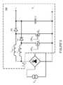
- FIG. 4illustrated is a schematic diagram of an exemplary power train employable in a power converter constructed according to the principles of the present invention. More specifically, the power train employs a boost topology with two interleaved boost regulator subcircuits and a boost inductor L boost formed by a magnetic device.
- the magnetic deviceincludes a common conductive winding or winding N C (coupled between terminals 1 and 2 of the magnetic device), a first conductive winding or winding N S1 (coupled between terminals 2 and 3 ), and a second conductive winding or winding N S2 (coupled between terminals 2 and 4 ).
- the first and second windings N S1 , N S2are electrically and magnetically coupled to the common winding N C .
- the first and second windings N S1 , N S2have equal numbers of turns and will hereinafter be represented with a reference symbol N S . Dots are illustrated in FIG. 4 adjacent to the windings to indicate the sense of each winding (i.e., the winding direction and the sense of the magnetically induced voltage therein).
- the interleaved boost regulator subcircuitsare controlled by a control circuit or controller (not shown) to provide an input current with high-power factor.
- One boost regulator subcircuitincludes a first diode D 1 and a first power switch S 1 , and a portion of the magnetic device that includes the common winding N c and the first winding N S1 .
- the other boost regulator subcircuitincludes a second diode D 2 and a second power switch S 2 , and a portion of the magnetic device that includes the common winding N c and the second winding N S2 .
- the output currents i 1 , i 2 from the boost regulator subcircuits of the power trainare interleaved and flow through the first and second diodes D 1 , D 2 , respectively, into an output filter capacitor C.
- the input currents to the boost regulator subcircuitsare interleaved and form the input current i in , through the common winding N c .
- the first and second power switches S 1 , S 2are controlled by first and second control signals GD S , GD S2 , respectively, to provide duty-cycle control for each of the two interleaved boost regulator subcircuits.
- the first and second control signals GD S1 , GD S2may be controlled 180 degrees out of phase with respect to each other, and provide a common duty cycle D for each boost regulator subcircuit.
- a load, represented by current source 408is coupled to output terminals 405 , 406 of the power converter and draws an output current i o .
- a common winding N C with selected turnshas been described herein as being formed around a center leg of a magnetic core of the magnetic device.
- the common winding N C with selected turnsmay be formed around a common leg of a magnetic core that is not geometrically a center leg.
- the terms “center” and “common” as illustrated and used herein with reference to a leg of a magnetic corehave a similar meaning, and include a leg of a magnetic core that may not be geometrically located as a center leg.
- the magnetic deviceis a boost inductor L boost with rectilinear construction and with single-layer windings.
- the magnetic deviceincludes the common winding N c wound around a common leg 505 of the magnetic core, which may be a center leg of the magnetic core, and be electrically and magnetically coupled to first and second windings N S1 , N S2 , each formed in a single layer, and each wound around separate legs (e.g., first and second outer legs 510 , 515 , respectively) of the magnetic core.
- a common flux ⁇ cflows through the common leg 505 of the magnetic core.
- First and second fluxes ⁇ 1 , ⁇ 2flow through the first and second outer legs 510 , 515 , respectively, of the magnetic core.
- the first and second windings N S1 , N S2are each conventionally formed as a single layer on the vertical walls of the “E” portion of the magnetic core, which limits the electrical conductivity of these windings.
- Terminals 1 , 2 , 3 , and 4 of the magnetic device illustrated in FIG. 5correspond to terminals similarly numbered and described with reference to FIG. 4 .
- a gap 520e.g., an air gap or a gap of other substantially nonmagnetic material
- gapscan be formed between the upper surfaces of the first and second outer legs 510 , 515 and/or the lower surface of the upper cross-member 525 .
- gapscan be formed between upper surfaces of all the legs 505 , 510 , 515 and the lower surface of the upper cross-member 525 .
- the sense of the winding directionsis illustrated by the drawings of the windings N C , N S1 , N S2 in FIG. 5 .
- the sense of all the windings N C , N S1 , N S2can be reversed to produce the same result, but with magnetic fluxes flowing in opposite directions.
- the first and second windings N S1 , N S2can be electrically coupled together external to the magnetic device.
- the common winding N Ccan be separated into two winding parts that can be electrically coupled together external to the magnetic device.
- the magnetic deviceincludes first and second U-shaped core pieces 602 , 603 , separated by a rectilinear core piece or central rectilinear core piece 601 (formed of a magnetic material).
- the first and second U-shaped core pieces 602 , 603form a portion of a toroidal core and are preferably formed of high permeability magnetic material, such as a soft ferrite.
- the conductive windingssuch as first and second conductive windings or windings N s1 , N s2 , are each formed about, along substantially the full span or substantially an entire curved length of the first and second U-shaped core pieces 602 , 603 , respectively.
- a third conductive winding or winding (e.g., a common or center conductive winding) N cis formed about the rectilinear core piece 601 , and is electrically coupled to said first and second conductive windings N s1 , N s2 .
- the magnetic device illustrated hereinintegrates and couples three inductors into one magnetic device.
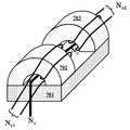
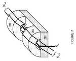
- FIG. 7illustrated is a diagram of an embodiment of a magnetic device constructed according to the principles of the present invention.
- the magnetic deviceincludes first and second U-shaped core pieces 702 , 703 .
- the first and second U-shaped core pieces 702 , 703are now positioned on a common surface of a rectilinear core piece or central rectilinear core piece 701 .
- the first and second U-shaped core pieces 702 , 703are again preferably formed of high permeability magnetic material, such as a magnetic material with a relative permeability greater than 50.
- the first and second U-shaped core pieces 702 , 703may be formed of a soft ferrite.
- the first and second conductive windings or windings N s1 , N s2may each be formed about or along substantially the full span of the first and second U-shaped core pieces 702 , 703 , respectively.
- the first and second conductive windings N s1 , N s2are illustrated spanning only a portion of the first and second U-shaped core pieces 702 , 703 , respectively.
- a third conductive winding or winding (e.g., a common or center conductive winding) N cwhich may be formed as a staple, is again formed about the rectilinear core piece 701 .
- the center leg 505 of the magnetic deviceincludes a gap or low-permeability “spacer” 520 in which a substantial portion of the magnetic energy of the magnetic device is stored.
- gapsmay be included in the flux paths of the outer legs formed by the first and second U-shaped core pieces.
- a gapcan be formed, without limitation, of a nonmagnetic material or a magnetic material of low permeability such as air, a plastic material, or a powdered soft ferrite distributed in a nonmagnetic matrix such as a resin or an epoxy.
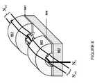
- FIG. 8illustrated is a diagram of an embodiment of a magnetic device constructed according to the principles of the present invention.
- the magnetic deviceincludes first and second U-shaped core pieces 802 , 803 positioned on a common surface of the rectilinear core piece or central rectilinear core piece 801 .
- First and second gaps 804 , 805which may be formed of nonmagnetic spacers, are positioned between the first and second U-shaped core pieces 802 , 803 , respectively, and the rectilinear core piece 801 to reduce mismatch of magnetic flux in the first and second U-shaped core pieces 802 , 803 due to currents flowing in first and second conductive windings N s1 , N s2 .
- a third conductive winding or winding(e.g., a common or center conductive winding) N c is formed about the rectilinear core piece 801 .
- the magnetic deviceincludes first and second U-shaped core pieces 902 , 903 positioned on a common surface of a rectilinear core piece or central rectilinear core piece 901 .
- the rectilinear core piece 901is constructed of magnetic material with a distributed gap. In other words, it is constructed of a magnetic material with a lower relative permeability than the relative permeability of the first and second U-shaped core pieces 902 , 903 , such as a powdered soft ferrite distributed in a nonmagnetic matrix such as a resin or an epoxy.
- a gapis formed in series with flux flowing in a common or center leg (e.g., the rectilinear core piece 901 ) of the magnetic structure, as well as gaps formed in series with flux flowing in the outer legs (e.g., the first and second U-shaped core pieces 902 , 903 ).
- Such use of disparate magnetic materials, such as a higher relative magnetic permeability of the first and second U-shaped core pieces 902 , 903 compared to the relative magnetic permeability of the rectilinear core piece 901enables construction of a magnetic structure without the need to insert physical spacers to produce series low-permeability gaps, and without the need to accurately shorten the center or common leg of an “E” core piece to produce a series air gap for a flux flowing therein, thereby reducing a manufacturing cost.
- the magnetic deviceincludes a rectilinear core piece formed of a magnetic material.
- the rectilinear core piecemay be formed with a distributed air gap.
- the magnetic devicealso includes first and second U-shaped core pieces formed of a high relative permeability magnetic material and positioned on the rectilinear core piece.
- the first and second U-shaped core piecesmay be positioned on a common surface of the rectilinear core piece, and may form a portion of a toroidal core.
- a nonmagnetic spacermay be positioned between one of the first and second U-shaped core pieces and a surface of the rectilinear core piece.
- a relative permeability of the rectilinear core pieceis substantially lower than the relative permeability of the first and second U-shaped core pieces.
- the magnetic devicealso includes first and second conductive windings formed about the first and second U-shaped core pieces, respectively.
- the first and second conductive windingsmay be formed over substantially an entire curved length of the first and second U-shaped core pieces, respectively.
- the magnetic devicemay also include a third conductive winding (e.g., a common or center conductive winding, or as a staple) formed about the rectilinear core piece, and electrically coupled to the first and second conductive windings.
- a power converter including a magnetic device including U-shaped core pieces positioned on a rectilinear core piece and related methods of forming the sameare submitted for illustrative purposes only. While a magnetic structure has been described in the environment of a power converter, the magnetic structure may also be applied to other systems such as, without limitation, a power amplifier and a motor controller.
Landscapes
- Engineering & Computer Science (AREA)
- Power Engineering (AREA)
- Chemical & Material Sciences (AREA)
- Composite Materials (AREA)
- Manufacturing & Machinery (AREA)
- Dc-Dc Converters (AREA)
Abstract
Description
This application claims the benefit of U.S. Provisional Application No. 61/165,184, entitled “Magnetic Device Formed With U-Shaped Core Pieces and Power Converter Employing The Same,” filed on Mar. 31, 2009, which application is incorporated herein by reference.
The present invention is directed, in general, to power electronics and, more specifically, to a magnetic device employable in a power converter.
A switched-mode power converter (also referred to as a “power converter” or “regulator”) is a power supply or power processing circuit that converts an input voltage waveform into a specified output voltage waveform. DC-DC power converters convert a direct current (“dc”) input voltage into a dc output voltage. Controllers associated with the power converters manage an operation thereof by controlling the conduction periods of power switches employed therein. Generally, the controllers are coupled between an input and output of the power converter in a feedback loop configuration (also referred to as a “control loop” or “closed control loop”).
To produce a dc output voltage, power converters employ magnetic devices such as inductors and transformers. A high-frequency alternating current (“ac”) voltage is applied to a winding of the magnetic device that is typically converted to another voltage level by an inductive action of the magnetic device. The converted voltage level is rectified by a diode or an active semiconductor device to produce the dc output voltage.
To produce a high level of power conversion efficiency, magnetic devices are often formed with windings wound in a single layer to reduce the proximity effect produced by high-frequency currents flowing in a proximate winding turn. The proximity effect causes high-frequency currents to flow predominantly in only a portion of a conductive winding, thereby increasing the effective resistance of the winding.
Magnetic devices are conventionally constructed with rectilinear core pieces such as “E” and “I” core pieces employed to form a high-frequency transformer or inductor. From practical manufacturing considerations, such designs require that a single-layer winding be formed on the vertical walls of the “E” portion of the magnetic core. Designs with such winding structures do not utilize the horizontal walls of the “E” or the “I” core pieces of the magnetic core, and accordingly introduce a high level of power losses.
Accordingly, what is needed in the art is a physical structure for a magnetic device and related method that provides a configuration to enable a wider distribution of winding turns to avoid the deficiencies in the prior art.
These and other problems are generally solved or circumvented, and technical advantages are generally achieved, by advantageous embodiments of the present invention, including a magnetic device formed with U-shaped core pieces employable in a power converter, and a method of forming the same. In one embodiment, the magnetic device includes a rectilinear core piece formed of a magnetic material, and first and second U-shaped core pieces positioned on the rectilinear core piece. The magnetic device also includes first and second conductive windings formed about the first and second U-shaped core pieces, respectively.
The foregoing has outlined rather broadly the features and technical advantages of the present invention in order that the detailed description of the invention that follows may be better understood. Additional features and advantages of the invention will be described hereinafter, which form the subject of the claims of the invention. It should be appreciated by those skilled in the art that the conception and specific embodiment disclosed may be readily utilized as a basis for modifying or designing other structures or processes for carrying out the same purposes of the present invention. It should also be realized by those skilled in the art that such equivalent constructions do not depart from the spirit and scope of the invention as set forth in the appended claims.
For a more complete understanding of the present invention, reference is now made to the following descriptions taken in conjunction with the accompanying drawings, in which:
Corresponding numerals and symbols in the different figures generally refer to corresponding parts unless otherwise indicated, and may not be redescribed in the interest of brevity after the first instance. The FIGUREs are drawn to illustrate the relevant aspects of exemplary embodiments.
The making and using of the present exemplary embodiments are discussed in detail below. It should be appreciated, however, that the present invention provides many applicable inventive concepts that can be embodied in a wide variety of specific contexts. The specific embodiments discussed are merely illustrative of specific ways to make and use the invention, and do not limit the scope of the invention.
The present invention will be described with respect to exemplary embodiments in a specific context, namely, a magnetic device including a U-shaped core piece, and a method of forming the same. The magnetic device including a U-shaped core piece provides improved power conversion efficiency by accommodating a larger physical space for turns of a single-layer winding of a conductive material formed thereabout. While the principles of the present invention will be described in the environment of a magnetic device for a power converter, any application that may benefit from a magnetic device such as a power amplifier or a motor controller is well within the broad scope of the present invention.
Referring initially toFIG. 1 , illustrated is a block diagram of an embodiment of a power converter including a magnetic device constructed according to the principles of the present invention. The power converter is coupled to a source of electrical power such as an ac mains represented by the ac power source providing an input voltage Vin. The power converter includes apower train 105 that is controlled by acontroller 110. Thecontroller 110 generally measures an operating characteristic of the power converter such as an output voltage Vcand controls a duty cycle D of one or more power switches therein in response to the measured operating characteristic to regulate the characteristic. The power converter may form a section of a power supply and provide power to another subsystem thereof, such as an isolating dc-dc power converter coupled to an output thereof that provides a regulated voltage to a load. Thepower train 105 may employ a boost topology as described herein. Thepower train 105 of the power converter includes a plurality of power switches coupled to a magnetic device to provide the power conversion function.
Turning now toFIG. 2 , illustrated is a schematic diagram of an exemplary power train (including a boost topology)201 employable in a power converter constructed according to the principles of the present invention. Thepower train 201 of the power converter receives an input voltage Vin(e.g., an unregulated ac input voltage) from a source of electrical power such as ac mains at an input thereof and provides a regulated output voltage VCatoutput terminals rectifier bridge 203 to a boost inductor Lboost. During a primary interval D, an input current iinincreases and flows through the boost inductor Lboostto local circuit ground. The boost inductor Lboostis generally formed with a single-layer winding to reduce the proximity effect to increase the efficiency of the power converter.
The duty cycle for thepower train 201 depends in steady state on the ratio of the input and output voltages Vin, Vc, respectively, according to the equation:
During a complementary interval 1-D, the main power switch S1is transitioned to a non-conducting state and an auxiliary power switch (e.g., the diode D1) conducts. In an alternative circuit arrangement, the auxiliary power switch D1 may include a second active power switch that is controlled to conduct by a complementary gate drive signal. The auxiliary power switch D1 provides a path to maintain the continuity of the input current iinflowing through the boost inductor Lboost. During the complementary interval 1-D, the input current iin, flowing through the boost inductor Lboostdecreases, and may become zero and remain zero for a period of time resulting in a “discontinuous conduction mode” of operation.
During the complementary interval 1-D, the input current iinflowing through the boost inductor Lboostflows through the diode D1 (i.e., the auxiliary power switch) into an output filter capacitor C. In general, the duty cycle of the main power switch S1(and the complementary duty cycle of the auxiliary power switch D1) may be adjusted to maintain a regulation of the output voltage VCof the power converter. Those skilled in the art understand that conduction periods for the main and auxiliary power switches S1, D1 may be separated by a small time interval by the use of “snubber” circuit elements (not shown) or by control circuit timing to avoid cross conduction current therebetween, and beneficially to reduce the switching losses associated with the power converter. Circuit and control techniques to avoid cross conduction currents between power switches are well understood in the art and will not be described further in the interest of brevity. The boost inductor Lboostis preferably formed with a single-layer winding as described previously hereinabove to reduce power loss associated with the proximity effect.
Turning now toFIG. 3 , illustrated is a schematic diagram of an exemplary power train (including a boost topology)300 employable in a power converter constructed according to the principles of the present invention. Thepower train 300 includes a first boost regulator subcircuit including a first boost inductor Lboost1, a first diode D1, and a first power switch S1that receives a first drive signal GDS1. Thepower train 300 includes a second boost regulator subcircuit including a second boost inductor Lboost2, a second diode D2, and a second power switch S2that receives a second drive signal GDS2. The first and second boost regulator subcircuits are generally controlled to operate roughly 180 degrees out of phase with respect to each other. Out-of-phase operation of the boost regulator subcircuits provides an interleaving effect that doubles the ripple frequency and reduces the ripple magnitude for the current drawn from arectifier bridge 303 and hence an ac input current iin. A similar effect is achieved for the current supplied to the output filter capacitor C. The reduction of switching ripple magnitude in the input current iinhelps reduce filtering requirements for an input filter (not shown) to reduce undesirable high-frequency components that may be conducted back to a source of electrical power such as an ac mains. Substantial benefits accrue from the interleaving effects between the two boost regulator subcircuits. The first and second boost inductors Lboost1, Lboost2are formed with single-layer windings in a magnetic structure. Remaining circuit elements inFIG. 3 and in following FIGUREs that are similar to those inFIG. 2 and will not be described again in the interest of brevity.
Turning now toFIG. 4 , illustrated is a schematic diagram of an exemplary power train employable in a power converter constructed according to the principles of the present invention. More specifically, the power train employs a boost topology with two interleaved boost regulator subcircuits and a boost inductor Lboostformed by a magnetic device. The magnetic device includes a common conductive winding or winding NC(coupled betweenterminals terminals 2 and3), and a second conductive winding or winding NS2(coupled betweenterminals 2 and4). The first and second windings NS1, NS2are electrically and magnetically coupled to the common winding NC. In an exemplary embodiment, the first and second windings NS1, NS2have equal numbers of turns and will hereinafter be represented with a reference symbol NS. Dots are illustrated inFIG. 4 adjacent to the windings to indicate the sense of each winding (i.e., the winding direction and the sense of the magnetically induced voltage therein).
In an exemplary embodiment, the interleaved boost regulator subcircuits are controlled by a control circuit or controller (not shown) to provide an input current with high-power factor. One boost regulator subcircuit includes a first diode D1 and a first power switch S1, and a portion of the magnetic device that includes the common winding Ncand the first winding NS1. The other boost regulator subcircuit includes a second diode D2 and a second power switch S2, and a portion of the magnetic device that includes the common winding Ncand the second winding NS2. The output currents i1, i2from the boost regulator subcircuits of the power train are interleaved and flow through the first and second diodes D1, D2, respectively, into an output filter capacitor C. Similarly, the input currents to the boost regulator subcircuits are interleaved and form the input current iin, through the common winding Nc. The first and second power switches S1, S2are controlled by first and second control signals GDS, GDS2, respectively, to provide duty-cycle control for each of the two interleaved boost regulator subcircuits. The first and second control signals GDS1, GDS2may be controlled 180 degrees out of phase with respect to each other, and provide a common duty cycle D for each boost regulator subcircuit. A load, represented bycurrent source 408 is coupled tooutput terminals
A common winding NCwith selected turns has been described herein as being formed around a center leg of a magnetic core of the magnetic device. In an alternative embodiment, the common winding NCwith selected turns may be formed around a common leg of a magnetic core that is not geometrically a center leg. Thus, the terms “center” and “common” as illustrated and used herein with reference to a leg of a magnetic core have a similar meaning, and include a leg of a magnetic core that may not be geometrically located as a center leg.
Turning now toFIG. 5 , illustrated is a diagram of an embodiment of a magnetic device constructed according to the principles of the present invention. The magnetic device is a boost inductor Lboostwith rectilinear construction and with single-layer windings. The magnetic device includes the common winding Ncwound around acommon leg 505 of the magnetic core, which may be a center leg of the magnetic core, and be electrically and magnetically coupled to first and second windings NS1, NS2, each formed in a single layer, and each wound around separate legs (e.g., first and secondouter legs common leg 505 of the magnetic core. First and second fluxes φ1, φ2flow through the first and secondouter legs
Turning now toFIG. 6 , illustrated is a diagram of an embodiment of a magnetic device constructed according to the principles of the present invention. The magnetic device includes first and secondU-shaped core pieces U-shaped core pieces U-shaped core pieces rectilinear core piece 601, and is electrically coupled to said first and second conductive windings Ns1, Ns2. The magnetic device illustrated herein integrates and couples three inductors into one magnetic device.
Turning now toFIG. 7 , illustrated is a diagram of an embodiment of a magnetic device constructed according to the principles of the present invention. The magnetic device includes first and secondU-shaped core pieces U-shaped core pieces rectilinear core piece 701. The first and secondU-shaped core pieces U-shaped core pieces U-shaped core pieces FIG. 7 , the first and second conductive windings Ns1, Ns2are illustrated spanning only a portion of the first and secondU-shaped core pieces rectilinear core piece 701.
As indicated illustrated inFIG. 5 , thecenter leg 505 of the magnetic device includes a gap or low-permeability “spacer”520 in which a substantial portion of the magnetic energy of the magnetic device is stored. In order to reduce mismatch of magnetic flux in the first and second U-shaped core pieces ofFIGS. 6 and 7 due to currents flowing in the first and second conductive windings Ns1, Ns2, respectively, gaps may be included in the flux paths of the outer legs formed by the first and second U-shaped core pieces. A gap can be formed, without limitation, of a nonmagnetic material or a magnetic material of low permeability such as air, a plastic material, or a powdered soft ferrite distributed in a nonmagnetic matrix such as a resin or an epoxy.
Turning now toFIG. 8 , illustrated is a diagram of an embodiment of a magnetic device constructed according to the principles of the present invention. The magnetic device includes first and secondU-shaped core pieces rectilinear core piece 801. First andsecond gaps U-shaped core pieces rectilinear core piece 801 to reduce mismatch of magnetic flux in the first and secondU-shaped core pieces rectilinear core piece 801.
Turning now toFIG. 9 , illustrated is a diagram of an embodiment of a magnetic device constructed according to the principles of the present invention. The magnetic device includes first and secondU-shaped core pieces U-shaped core pieces U-shaped core pieces 902,903). Such use of disparate magnetic materials, such as a higher relative magnetic permeability of the first and secondU-shaped core pieces
Thus, a magnetic device including a U-shaped core piece, and a method of forming the same has been introduced herein. In one embodiment, the magnetic device includes a rectilinear core piece formed of a magnetic material. The rectilinear core piece may be formed with a distributed air gap. The magnetic device also includes first and second U-shaped core pieces formed of a high relative permeability magnetic material and positioned on the rectilinear core piece. The first and second U-shaped core pieces may be positioned on a common surface of the rectilinear core piece, and may form a portion of a toroidal core. A nonmagnetic spacer may be positioned between one of the first and second U-shaped core pieces and a surface of the rectilinear core piece. Typically, a relative permeability of the rectilinear core piece is substantially lower than the relative permeability of the first and second U-shaped core pieces.
The magnetic device also includes first and second conductive windings formed about the first and second U-shaped core pieces, respectively. The first and second conductive windings may be formed over substantially an entire curved length of the first and second U-shaped core pieces, respectively. The magnetic device may also include a third conductive winding (e.g., a common or center conductive winding, or as a staple) formed about the rectilinear core piece, and electrically coupled to the first and second conductive windings.
Those skilled in the art should understand that the previously described embodiments of a power converter including a magnetic device including U-shaped core pieces positioned on a rectilinear core piece and related methods of forming the same are submitted for illustrative purposes only. While a magnetic structure has been described in the environment of a power converter, the magnetic structure may also be applied to other systems such as, without limitation, a power amplifier and a motor controller.
For a better understanding of power converters, see “Modern DC-to-DC Power Switch-mode Power Converter Circuits,” by Rudolph P. Severns and Gordon Bloom, Van Nostrand Reinhold Company, New York, N.Y. (1985) and “Principles of Power Electronics,” by J. G. Kassakian, M. F. Schlecht and G. C. Verghese, Addison-Wesley (1991). The aforementioned references are incorporated herein by reference in their entirety.
Also, although the present invention and its advantages have been described in detail, it should be understood that various changes, substitutions and alterations can be made herein without departing from the spirit and scope of the invention as defined by the appended claims. For example, many of the processes discussed above can be implemented in different methodologies and replaced by other processes, or a combination thereof.
Moreover, the scope of the present application is not intended to be limited to the particular embodiments of the process, machine, manufacture, composition of matter, means, methods, and steps described in the specification. As one of ordinary skill in the art will readily appreciate from the disclosure of the present invention, processes, machines, manufacture, compositions of matter, means, methods, or steps, presently existing or later to be developed, that perform substantially the same function or achieve substantially the same result as the corresponding embodiments described herein may be utilized according to the present invention. Accordingly, the appended claims are intended to include within their scope such processes, machines, manufacture, compositions of matter, means, methods, or steps.
Claims (20)
1. A magnetic device, comprising:
a rectilinear core piece formed of a magnetic material;
first and second U-shaped core pieces with a bottom surface of ends thereof positioned on a common surface of said rectilinear core piece, a relative permeability of said rectilinear core piece being substantially lower than a relative permeability of said first and second U-shaped core pieces;
first and second conductive windings formed about said first and second U-shaped core pieces, respectively; and
a third conductive winding formed about said rectilinear core piece and electrically coupled to said first and second conductive windings at a common terminal.
2. The magnetic device as recited inclaim 1 wherein said first and second conductive windings are formed over substantially an entire curved length of said first and second U-shaped core pieces, respectively.
3. The magnetic device as recited inclaim 1 wherein said first and second U-shaped core pieces are formed with a soft ferrite.
4. The magnetic device as recited inclaim 1 further comprising a nonmagnetic spacer positioned between said bottom surface of said ends of at least one of said first and second U-shaped core pieces and said common surface of said rectilinear core piece.
5. The magnetic device as recited inclaim 1 wherein said first and second U-shaped core pieces are separated by a portion of said common surface of said rectilinear core piece.
6. The magnetic device as recited inclaim 1 wherein said third conductive winding is formed as a staple.
7. The magnetic device as recited inclaim 1 wherein said first and second conductive windings are formed as a single layer about said first and second U-shaped core pieces, respectively.
8. The magnetic device as recited inclaim 1 wherein said rectilinear core piece is formed with a distributed gap.
9. The magnetic device as recited inclaim 1 wherein said first and second conductive windings are first and second secondary windings and said third conductive winding is a common winding coupled thereto.
10. The magnetic device as recited inclaim 1 wherein said first and the second U-shaped core pieces are each formed as a portion of a toroidal core.
11. A method of forming a magnetic device, comprising:
providing a rectilinear core piece of a magnetic material;
positioning a bottom surface of ends of first and second U-shaped core pieces on a common surface of said rectilinear core piece, a relative permeability of said rectilinear core piece being substantially lower than a relative permeability of said first and second U-shaped core pieces;
forming first and second conductive windings about said first and second U-shaped core pieces, respectively; and
forming a third conductive winding about said rectilinear core piece and electrically coupled to said first and second conductive windings at a common terminal.
12. The method as recited inclaim 11 wherein said first and second conductive windings are formed over substantially an entire curved length of said first and second U-shaped core pieces, respectively.
13. The method as recited inclaim 11 wherein said first and second U-shaped core pieces formed with a soft ferrite.
14. The method as recited inclaim 11 further comprising positioning a nonmagnetic spacer between said bottom surface of said ends of at least one of said first and second U-shaped core pieces and said common surface of said rectilinear core piece.
15. The method as recited inclaim 11 wherein said first and second U-shaped core pieces are separated by a portion of said common surface of said rectilinear core piece.
16. The method as recited inclaim 11 wherein said third conductive winding is formed as a staple.
17. The method as recited inclaim 11 wherein said first and second conductive windings are formed as a single layer about said first and second U-shaped core pieces, respectively.
18. The method as recited inclaim 11 wherein said rectilinear core piece is formed with a distributed gap.
19. The method as recited inclaim 11 wherein said first and second conductive windings are first and second secondary windings and said third conductive winding is a common winding coupled thereto.
20. The method as recited inclaim 11 wherein said first and the second U-shaped core pieces are each formed as a portion of a toroidal core.
Priority Applications (1)
| Application Number | Priority Date | Filing Date | Title |
|---|---|---|---|
| US12/751,650US9019061B2 (en) | 2009-03-31 | 2010-03-31 | Magnetic device formed with U-shaped core pieces and power converter employing the same |
Applications Claiming Priority (2)
| Application Number | Priority Date | Filing Date | Title |
|---|---|---|---|
| US16518409P | 2009-03-31 | 2009-03-31 | |
| US12/751,650US9019061B2 (en) | 2009-03-31 | 2010-03-31 | Magnetic device formed with U-shaped core pieces and power converter employing the same |
Publications (2)
| Publication Number | Publication Date |
|---|---|
| US20100254168A1 US20100254168A1 (en) | 2010-10-07 |
| US9019061B2true US9019061B2 (en) | 2015-04-28 |
Family
ID=42826062
Family Applications (1)
| Application Number | Title | Priority Date | Filing Date |
|---|---|---|---|
| US12/751,650Active2032-08-20US9019061B2 (en) | 2009-03-31 | 2010-03-31 | Magnetic device formed with U-shaped core pieces and power converter employing the same |
Country Status (3)
| Country | Link |
|---|---|
| US (1) | US9019061B2 (en) |
| CN (1) | CN102356438B (en) |
| WO (1) | WO2010114914A1 (en) |
Cited By (4)
| Publication number | Priority date | Publication date | Assignee | Title |
|---|---|---|---|---|
| US20150084422A1 (en)* | 2012-03-19 | 2015-03-26 | Kabushiki Kaisha Toyota Chuo Kenkyusho | Magnetic component, power converter and power supply system |
| US9379629B2 (en) | 2012-07-16 | 2016-06-28 | Power Systems Technologies, Ltd. | Magnetic device and power converter employing the same |
| US11004594B2 (en)* | 2017-07-07 | 2021-05-11 | Yazaki Corporation | Surge voltage reduction member |
| US11482369B2 (en)* | 2016-12-20 | 2022-10-25 | Lg Innotek Co., Ltd. | Magnetic core, coil component, and electronic component including same |
Families Citing this family (53)
| Publication number | Priority date | Publication date | Assignee | Title |
|---|---|---|---|---|
| US7280026B2 (en) | 2002-04-18 | 2007-10-09 | Coldwatt, Inc. | Extended E matrix integrated magnetics (MIM) core |
| US8125205B2 (en) | 2006-08-31 | 2012-02-28 | Flextronics International Usa, Inc. | Power converter employing regulators with a coupled inductor |
| US7675759B2 (en) | 2006-12-01 | 2010-03-09 | Flextronics International Usa, Inc. | Power system with power converters having an adaptive controller |
| US9197132B2 (en) | 2006-12-01 | 2015-11-24 | Flextronics International Usa, Inc. | Power converter with an adaptive controller and method of operating the same |
| US7468649B2 (en) | 2007-03-14 | 2008-12-23 | Flextronics International Usa, Inc. | Isolated power converter |
| CN102217181B (en) | 2008-11-14 | 2014-09-03 | 伟创力国际美国公司 | Driver for a synchronous rectifier and power converter employing the same |
| WO2010083511A1 (en) | 2009-01-19 | 2010-07-22 | Flextronics International Usa, Inc. | Controller for a power converter |
| WO2010083514A1 (en) | 2009-01-19 | 2010-07-22 | Flextronics International Usa, Inc. | Controller for a power converter |
| US9019061B2 (en) | 2009-03-31 | 2015-04-28 | Power Systems Technologies, Ltd. | Magnetic device formed with U-shaped core pieces and power converter employing the same |
| US9077248B2 (en) | 2009-06-17 | 2015-07-07 | Power Systems Technologies Ltd | Start-up circuit for a power adapter |
| US8514593B2 (en) | 2009-06-17 | 2013-08-20 | Power Systems Technologies, Ltd. | Power converter employing a variable switching frequency and a magnetic device with a non-uniform gap |
| US8643222B2 (en) | 2009-06-17 | 2014-02-04 | Power Systems Technologies Ltd | Power adapter employing a power reducer |
| US8638578B2 (en) | 2009-08-14 | 2014-01-28 | Power System Technologies, Ltd. | Power converter including a charge pump employable in a power adapter |
| US8976549B2 (en) | 2009-12-03 | 2015-03-10 | Power Systems Technologies, Ltd. | Startup circuit including first and second Schmitt triggers and power converter employing the same |
| US8520420B2 (en) | 2009-12-18 | 2013-08-27 | Power Systems Technologies, Ltd. | Controller for modifying dead time between switches in a power converter |
| US9246391B2 (en) | 2010-01-22 | 2016-01-26 | Power Systems Technologies Ltd. | Controller for providing a corrected signal to a sensed peak current through a circuit element of a power converter |
| US8787043B2 (en) | 2010-01-22 | 2014-07-22 | Power Systems Technologies, Ltd. | Controller for a power converter and method of operating the same |
| CN102870320B (en) | 2010-03-17 | 2016-11-02 | 电力系统技术有限公司 | The control system of power converter and operational approach thereof |
| KR20120020325A (en)* | 2010-08-30 | 2012-03-08 | 삼성전자주식회사 | Inductor core for power factor correction circuit |
| WO2012046534A1 (en)* | 2010-10-06 | 2012-04-12 | 三菱電機株式会社 | Power supply device |
| US8792257B2 (en) | 2011-03-25 | 2014-07-29 | Power Systems Technologies, Ltd. | Power converter with reduced power dissipation |
| KR101241564B1 (en)* | 2011-08-04 | 2013-03-11 | 전주대학교 산학협력단 | Couple inductor, Couple transformer and Couple inductor-transformer |
| JP5375922B2 (en) | 2011-10-18 | 2013-12-25 | 株式会社豊田自動織機 | Magnetic core and induction device |
| JP5887886B2 (en)* | 2011-11-30 | 2016-03-16 | 株式会社デンソー | Composite magnetic parts |
| US8792256B2 (en) | 2012-01-27 | 2014-07-29 | Power Systems Technologies Ltd. | Controller for a switch and method of operating the same |
| US9190898B2 (en) | 2012-07-06 | 2015-11-17 | Power Systems Technologies, Ltd | Controller for a power converter and method of operating the same |
| US9214264B2 (en)* | 2012-07-16 | 2015-12-15 | Power Systems Technologies, Ltd. | Magnetic device and power converter employing the same |
| US9099232B2 (en) | 2012-07-16 | 2015-08-04 | Power Systems Technologies Ltd. | Magnetic device and power converter employing the same |
| US9106130B2 (en) | 2012-07-16 | 2015-08-11 | Power Systems Technologies, Inc. | Magnetic device and power converter employing the same |
| US9240712B2 (en) | 2012-12-13 | 2016-01-19 | Power Systems Technologies Ltd. | Controller including a common current-sense device for power switches of a power converter |
| US9343991B2 (en) | 2013-01-18 | 2016-05-17 | General Electric Company | Current balance control for non-interleaved parallel bridge circuits in power converter |
| US9281761B2 (en) | 2013-01-18 | 2016-03-08 | General Electric Company | Control scheme for current balancing between parallel bridge circuits |
| US9537437B2 (en) | 2013-03-04 | 2017-01-03 | General Electric Company | Method and system for controlling switching frequency of a doubly-fed induction generator (DFIG) |
| US9048764B2 (en) | 2013-05-29 | 2015-06-02 | General Electric Company | Connection for improved current balancing in a parallel bridge power converter |
| US9362859B2 (en) | 2013-09-25 | 2016-06-07 | General Electric Company | System and method for controlling switching elements within a single-phase bridge circuit |
| US9300206B2 (en) | 2013-11-15 | 2016-03-29 | Power Systems Technologies Ltd. | Method for estimating power of a power converter |
| KR102318230B1 (en) | 2014-12-11 | 2021-10-27 | 엘지이노텍 주식회사 | Inductor |
| US9530553B1 (en)* | 2015-11-02 | 2016-12-27 | Globalfoundries Inc. | High performance inductor/transformer and methods of making such inductor/transformer structures |
| US10193534B2 (en)* | 2015-12-17 | 2019-01-29 | Garrity Power Services Llc | Wireless power system tuning apparatus |
| US10217559B2 (en)* | 2016-04-12 | 2019-02-26 | Virginia Tech Intellectual Properties, Inc. | Multiphase coupled and integrated inductors with printed circuit board (PBC) windings for power factor correction (PFC) converters |
| WO2017205644A1 (en)* | 2016-05-26 | 2017-11-30 | The Trustees Of The University Of Pennsylvania | Laminated magnetic cores |
| CN106158250A (en)* | 2016-09-18 | 2016-11-23 | 田村(中国)企业管理有限公司 | A kind of ring-shaped inductors |
| ES2801903T3 (en)* | 2017-10-03 | 2021-01-14 | Vestas Wind Sys As | Magnetically Immune Door Drivers Circuit |
| CN109905014B (en)* | 2017-12-08 | 2021-07-06 | 台达电子工业股份有限公司 | Passive Circuits and Power Converters |
| DE102018203054A1 (en) | 2018-03-01 | 2019-09-05 | Bayerische Motoren Werke Aktiengesellschaft | Voltage transformer with coupled PFC choke |
| JP6823627B2 (en) | 2018-09-05 | 2021-02-03 | 矢崎総業株式会社 | Wire distribution structure and wire harness |
| US12334239B2 (en) | 2018-10-26 | 2025-06-17 | The Trustees Of The University Of Pennsylvania | Patterned magnetic cores |
| CN109660120A (en)* | 2018-12-29 | 2019-04-19 | Tcl空调器(中山)有限公司 | Switching circuit, control method of switching circuit, power supply device and air conditioner |
| US20210210281A1 (en)* | 2019-07-24 | 2021-07-08 | Rockwell Collins, Inc. | Coupled Output Inductor and System |
| WO2024170065A1 (en)* | 2022-02-14 | 2024-08-22 | Premo, Sl | A power electromagnetic device and fabrication method thereof |
| CN115313822B (en)* | 2022-10-10 | 2023-11-07 | 深圳市首航新能源股份有限公司 | A magnetic integrated inductor and inverter |
| FR3142851B1 (en)* | 2022-12-06 | 2025-01-03 | Thales Sa | Inductance variation module and radiofrequency filter comprising such a module |
| FR3152633A1 (en)* | 2023-08-31 | 2025-03-07 | Safran | MAGNETIC CORE WITH OPTIMIZED CLOSURE |
Citations (358)
| Publication number | Priority date | Publication date | Assignee | Title |
|---|---|---|---|---|
| US1376978A (en) | 1917-11-24 | 1921-05-03 | Cutler Hammer Mfg Co | Regulator for alternating currents |
| US2473662A (en) | 1944-08-02 | 1949-06-21 | Lorain Prod Corp | Rectifying arrangement |
| US3007060A (en) | 1959-03-23 | 1961-10-31 | Gen Dynamics Corp | Circuitry for independently delaying the leading and trailing edges of an input pulse |
| US3142809A (en) | 1961-04-04 | 1964-07-28 | Andrew A Halacsy | Cooling arrangement for electrical apparatus having at least one multilayer winding |
| US3346798A (en) | 1963-08-08 | 1967-10-10 | Gen Electric | Regulator for inverter |
| US3358210A (en) | 1964-06-25 | 1967-12-12 | Gen Electric | Voltage regulator |
| US3433998A (en) | 1965-04-24 | 1969-03-18 | Philips Corp | Circuit arrangement for frame correction |
| US3484562A (en) | 1966-09-21 | 1969-12-16 | Nortronics Co | Magnetic transducer with clamped body sections to hold core pieces |
| US3546571A (en) | 1968-06-21 | 1970-12-08 | Varo | Constant voltage ferroresonant transformer utilizing unequal area core structure |
| US3553620A (en) | 1967-09-14 | 1971-01-05 | Ibm | Combined transformer and indicator device |
| US3602795A (en) | 1969-10-16 | 1971-08-31 | Ibm | Transformerless power supply |
| US3622868A (en) | 1970-02-06 | 1971-11-23 | Joachim H Todt | Regulating power transformer with magnetic shunt |
| US3659191A (en)* | 1971-04-23 | 1972-04-25 | Westinghouse Electric Corp | Regulating transformer with non-saturating input and output regions |
| US3681679A (en) | 1971-05-07 | 1972-08-01 | Kheemoy Chung | Constant voltage transformer three-phase ferro resonant |
| US3708744A (en) | 1971-08-18 | 1973-01-02 | Westinghouse Electric Corp | Regulating and filtering transformer |
| US3708742A (en) | 1971-06-30 | 1973-01-02 | Ibm | High dc to low dc voltage converter |
| US4019122A (en) | 1974-08-14 | 1977-04-19 | Telcon-Magnetic Cores Limited | Stabilized power supplies |
| US4075547A (en) | 1975-07-23 | 1978-02-21 | Frequency Technology, Inc. | Voltage regulating transformer |
| US4202031A (en) | 1978-11-01 | 1980-05-06 | General Electric Company | Static inverter employing an assymetrically energized inductor |
| US4257087A (en) | 1979-04-02 | 1981-03-17 | California Institute Of Technology | DC-to-DC switching converter with zero input and output current ripple and integrated magnetics circuits |
| US4274071A (en) | 1979-11-16 | 1981-06-16 | Bell Telephone Laboratories, Incorporated | Three-phase ferroresonant transformer structure embodied in one unitary transformer construction |
| US4327348A (en) | 1977-05-20 | 1982-04-27 | Tdk Electronics Co., Ltd. | Variable leakage transformer |
| JPS5797361A (en) | 1980-12-05 | 1982-06-17 | Takaharu Miyazaki | Voltage step-down circuit |
| US4393157A (en)* | 1978-10-20 | 1983-07-12 | Hydro Quebec | Variable inductor |
| JPS58161308A (en)* | 1982-03-18 | 1983-09-24 | Matsushita Electric Ind Co Ltd | thin transformer |
| US4471423A (en) | 1982-02-17 | 1984-09-11 | Hase A M | Multi-voltage DC output with single reactor voltage control |
| US4499481A (en) | 1983-09-14 | 1985-02-12 | The United States Of America As Represented By The Secretary Of The Navy | Heterojunction Schottky gate MESFET with lower channel ridge barrier |
| US4570174A (en) | 1981-08-21 | 1986-02-11 | The United States Of America As Represented By The Secretary Of The Army | Vertical MESFET with air spaced gate electrode |
| US4577268A (en) | 1982-12-20 | 1986-03-18 | Rca Corporation | Switching dc-to-dc converters |
| US4581691A (en) | 1984-04-23 | 1986-04-08 | At&T Bell Laboratories | Balanced constant current sensing circuit inherently immune to longitudinal currents |
| US4613841A (en) | 1983-11-30 | 1986-09-23 | General Electric Company | Integrated transformer and inductor |
| US4636823A (en) | 1984-06-05 | 1987-01-13 | California Institute Of Technology | Vertical Schottky barrier gate field-effect transistor in GaAs/GaAlAs |
| WO1987000991A1 (en) | 1985-08-09 | 1987-02-12 | Pham Dang Tam | High power electronic voltage converter-reducer |
| US4660136A (en) | 1985-01-24 | 1987-04-21 | Honeywell Inc. | Single regulation power supply with load compensation of an auxiliary voltage output |
| US4770668A (en) | 1988-01-19 | 1988-09-13 | National Starch And Chemical Corporation | Ethylene urea compositions useful as permanent press promoting chemicals |
| US4770667A (en) | 1982-12-07 | 1988-09-13 | Board Of Regents, U T Systems | Use of substituted 2-(2'-hydroxyaryl)-2H-benzotriazolesulfonates as photostabilizing agents for natural and synthetic fibres |
| US4785387A (en) | 1986-04-28 | 1988-11-15 | Virginia Tech Intellectual Properties, Inc. | Resonant converters with secondary-side resonance |
| US4799138A (en) | 1986-09-26 | 1989-01-17 | Kabelmetal Electro Gesellschaft Mit Beschrankter Haftung | Circuit for producing an alternating voltage |
| US4803609A (en) | 1985-10-31 | 1989-02-07 | International Business Machines Corporation | D. C. to D. C. converter |
| US4823249A (en) | 1987-04-27 | 1989-04-18 | American Telephone And Telegraph Company At&T Bell Laboratories | High-frequency resonant power converter |
| US4837496A (en) | 1988-03-28 | 1989-06-06 | Linear Technology Corporation | Low voltage current source/start-up circuit |
| US4853668A (en) | 1987-12-23 | 1989-08-01 | Bloom Gordon E | Integrated magnetic converter core |
| US4866367A (en) | 1988-04-11 | 1989-09-12 | Virginia Tech Intellectual Properties, Inc. | Multi-loop control for quasi-resonant converters |
| US4876638A (en) | 1988-02-10 | 1989-10-24 | Electronic Research Group, Inc. | Low-noise switching power supply having variable reluctance transformer |
| US4887061A (en) | 1988-01-18 | 1989-12-12 | Tdk Corporation | Transformer for a flyback type converter |
| US4899271A (en) | 1987-07-22 | 1990-02-06 | Scanpower | Power supply circuit |
| US4903089A (en) | 1988-02-02 | 1990-02-20 | Massachusetts Institute Of Technology | Vertical transistor device fabricated with semiconductor regrowth |
| US4922400A (en) | 1989-08-03 | 1990-05-01 | Sundstrand Corporation | Neutral forming circuit |
| US4962354A (en) | 1989-07-25 | 1990-10-09 | Superconductivity, Inc. | Superconductive voltage stabilizer |
| US4964028A (en) | 1989-10-26 | 1990-10-16 | Plessey Electronic Systems Corp. | Current limited quasi-resonant voltage converting power supply |
| US4999759A (en) | 1989-09-27 | 1991-03-12 | Cavagnolo Gian P | Multiple output switching power supply having one controlled output voltage and load compensation |
| US5003277A (en) | 1988-08-15 | 1991-03-26 | Mitsubishi Denki Kabushiki Kaisha | Phase-shifting transformer with a six-phase core |
| US5027264A (en) | 1989-09-29 | 1991-06-25 | Wisconsin Alumni Research Foundation | Power conversion apparatus for DC/DC conversion using dual active bridges |
| JPH03215911A (en) | 1990-01-19 | 1991-09-20 | Matsushita Electric Ind Co Ltd | Variable inductor |
| US5068756A (en) | 1989-02-16 | 1991-11-26 | Texas Instruments Incorporated | Integrated circuit composed of group III-V compound field effect and bipolar semiconductors |
| US5106778A (en) | 1988-02-02 | 1992-04-21 | Massachusetts Institute Of Technology | Vertical transistor device fabricated with semiconductor regrowth |
| US5126714A (en) | 1990-12-20 | 1992-06-30 | The United States Of America As Represented By The Secretary Of The Navy | Integrated circuit transformer |
| US5132888A (en) | 1991-01-07 | 1992-07-21 | Unisys Corporation | Interleaved bridge converter |
| US5134771A (en) | 1991-07-05 | 1992-08-04 | General Electric Company | Method for manufacturing and amorphous metal core for a transformer that includes steps for reducing core loss |
| US5172309A (en) | 1991-08-07 | 1992-12-15 | General Electric Company | Auxiliary quasi-resonant dc link converter |
| US5177460A (en) | 1990-01-04 | 1993-01-05 | Dhyanchand P John | Summing transformer for star-delta inverter having a single secondary winding for each group of primary windings |
| US5182535A (en) | 1989-12-19 | 1993-01-26 | Dhyanchand P John | Summing transformer core for star-delta inverter having a separate secondary winding for each primary winding |
| US5204809A (en) | 1992-04-03 | 1993-04-20 | International Business Machines Corporation | H-driver DC-to-DC converter utilizing mutual inductance |
| US5206621A (en) | 1990-07-02 | 1993-04-27 | General Electric Company | Barrel-wound conductive film transformer |
| US5208739A (en) | 1992-01-07 | 1993-05-04 | Powercube Corporation | Integrated magnetic power converter |
| US5223449A (en) | 1989-02-16 | 1993-06-29 | Morris Francis J | Method of making an integrated circuit composed of group III-V compound field effect and bipolar semiconductors |
| US5225971A (en) | 1992-01-08 | 1993-07-06 | International Business Machines Corporation | Three coil bridge transformer |
| US5231037A (en) | 1992-04-30 | 1993-07-27 | Texas Instruments Incorporated | Method of making a power VFET device using a p+ carbon doped gate layer |
| US5244829A (en) | 1992-07-09 | 1993-09-14 | Texas Instruments Incorporated | Organometallic vapor-phase epitaxy process using (CH3)3 As and CCl4 for improving stability of carbon-doped GaAs |
| US5262930A (en) | 1992-06-12 | 1993-11-16 | The Center For Innovative Technology | Zero-voltage transition PWM converters |
| US5282126A (en) | 1991-08-01 | 1994-01-25 | U.S. Philips Corporation | Start circuit for a switched mode power supply |
| US5285396A (en) | 1991-01-11 | 1994-02-08 | Tadamasa Aoyama | Device for evaluating race horse performance based on temperature |
| US5291382A (en) | 1991-04-10 | 1994-03-01 | Lambda Electronics Inc. | Pulse width modulated DC/DC converter with reduced ripple current coponent stress and zero voltage switching capability |
| US5303138A (en) | 1993-04-29 | 1994-04-12 | At&T Bell Laboratories | Low loss synchronous rectifier for application to clamped-mode power converters |
| US5305191A (en) | 1992-04-20 | 1994-04-19 | At&T Bell Laboratories | Drive circuit for zero-voltage switching power converter with controlled power switch turn-on |
| US5335163A (en)* | 1990-11-14 | 1994-08-02 | Scanpower | Power supply circuit with integrated magnetic components |
| US5336985A (en) | 1992-11-09 | 1994-08-09 | Compaq Computer Corp. | Tapped inductor slave regulating circuit |
| US5342795A (en) | 1992-04-30 | 1994-08-30 | Texas Instruments Incorporated | Method of fabricating power VFET gate-refill |
| US5343140A (en) | 1992-12-02 | 1994-08-30 | Motorola, Inc. | Zero-voltage-switching quasi-resonant converters with multi-resonant bipolar switch |
| US5353001A (en) | 1991-01-24 | 1994-10-04 | Burr-Brown Corporation | Hybrid integrated circuit planar transformer |
| US5369042A (en) | 1993-03-05 | 1994-11-29 | Texas Instruments Incorporated | Enhanced performance bipolar transistor process |
| US5374887A (en) | 1993-11-12 | 1994-12-20 | Northern Telecom Limited | Inrush current limiting circuit |
| US5399968A (en) | 1992-01-31 | 1995-03-21 | Northrop Grumman Corporation | Eddy current probe having body of high permeability supporting drive coil and plural sensors |
| US5450307A (en) | 1993-02-19 | 1995-09-12 | Sony Corporation | Switching power source apparatus |
| US5459652A (en) | 1994-01-28 | 1995-10-17 | Compaq Computer Corp. | Boot strap circuit for power up control of power supplies |
| US5461555A (en) | 1990-12-27 | 1995-10-24 | Nec Corporation | Flyback converter having a high efficiency irrespective of magnitude of a load |
| US5468661A (en) | 1993-06-17 | 1995-11-21 | Texas Instruments Incorporated | Method of making power VFET device |
| US5477175A (en) | 1993-10-25 | 1995-12-19 | Motorola | Off-line bootstrap startup circuit |
| US5508903A (en) | 1995-04-21 | 1996-04-16 | Alexndrov; Felix | Interleaved DC to DC flyback converters with reduced current and voltage stresses |
| US5523673A (en) | 1994-03-04 | 1996-06-04 | Marelco Power Systems, Inc. | Electrically controllable inductor |
| US5539630A (en) | 1993-11-15 | 1996-07-23 | California Institute Of Technology | Soft-switching converter DC-to-DC isolated with voltage bidirectional switches on the secondary side of an isolation transformer |
| US5554561A (en) | 1993-04-30 | 1996-09-10 | Texas Instruments Incorporated | Epitaxial overgrowth method |
| US5555494A (en) | 1993-09-13 | 1996-09-10 | Morris; George Q. | Magnetically integrated full wave DC to DC converter |
| US5572079A (en)* | 1994-12-21 | 1996-11-05 | Magnetic Bearing Technologies, Inc. | Magnetic bearing utilizing brushless generator |
| US5581224A (en)* | 1994-10-14 | 1996-12-03 | Murata Manufacturing Co., Ltd. | Choke coil for eliminating common mode noise and differential mode noise |
| US5610085A (en) | 1993-11-29 | 1997-03-11 | Texas Instruments Incorporated | Method of making a vertical FET using epitaxial overgrowth |
| US5624860A (en) | 1993-04-30 | 1997-04-29 | Texas Instruments Incorporated | Vertical field effect transistor and method |
| EP0665634B1 (en) | 1994-01-31 | 1997-05-14 | Siemens Aktiengesellschaft | Circuit arrangement with a field effect transistor |
| US5663876A (en) | 1995-09-25 | 1997-09-02 | Lucent Technologies Inc. | Circuit and method for achieving zero ripple current in the output of a converter |
| US5700703A (en) | 1996-08-06 | 1997-12-23 | Motorola | Method of fabricating buried control elements in semiconductor devices |
| US5712189A (en) | 1993-04-30 | 1998-01-27 | Texas Instruments Incorporated | Epitaxial overgrowth method |
| US5719544A (en) | 1991-09-13 | 1998-02-17 | Vlt Corporation | Transformer with controlled interwinding coupling and controlled leakage inducances and circuit using such transformer |
| US5731666A (en)* | 1996-03-08 | 1998-03-24 | Magnetek Inc. | Integrated-magnetic filter having a lossy shunt |
| US5734564A (en) | 1996-07-26 | 1998-03-31 | Lucent Technologies Inc. | High-efficiency switching power converter |
| US5736842A (en) | 1996-07-11 | 1998-04-07 | Delta Electronics, Inc. | Technique for reducing rectifier reverse-recovery-related losses in high-voltage high power converters |
| US5742491A (en) | 1995-08-09 | 1998-04-21 | Lucent Technologies Inc. | Power converter adaptively driven |
| US5756375A (en) | 1995-06-14 | 1998-05-26 | Texas Instruments Incorporated | Semiconductor growth method with thickness control |
| US5760671A (en) | 1995-09-15 | 1998-06-02 | Celestica Inc. | Transformer with dual flux path |
| US5783984A (en) | 1995-06-16 | 1998-07-21 | Hughes Electronics | Method and means for combining a transformer and inductor on a single core structure |
| US5784266A (en) | 1996-06-14 | 1998-07-21 | Virginia Power Technologies, Inc | Single magnetic low loss high frequency converter |
| US5804943A (en) | 1995-05-12 | 1998-09-08 | Texas Instruments Incorporated | Resonant bilateral charging and discharging circuit |
| US5815386A (en) | 1997-06-19 | 1998-09-29 | Factor One, Inc. | Snubber for zero current switched networks |
| US5815383A (en) | 1995-06-15 | 1998-09-29 | Supertex, Inc. | High voltage start-up circuit and method therefor |
| US5864110A (en) | 1996-11-22 | 1999-01-26 | Sansha Electric Manufacturing Company, Limited | Power supply apparatus for plasma arc utilizing equipment |
| US5870299A (en) | 1997-05-28 | 1999-02-09 | Lucent Technologies Inc. | Method and apparatus for damping ringing in self-driven synchronous rectifiers |
| US5880942A (en) | 1997-03-17 | 1999-03-09 | Acer Peripherals Inc. | Power supply device with low power dissipation |
| US5886508A (en) | 1997-08-29 | 1999-03-23 | Computer Products, Inc. | Multiple output voltages from a cascaded buck converter topology |
| US5889660A (en) | 1997-03-06 | 1999-03-30 | Eaton Corporation | Isolated power supply for indicator light |
| US5889373A (en)* | 1996-12-30 | 1999-03-30 | General Electric Company | Fluorescent lamp ballast with current feedback using a dual-function magnetic device |
| US5900822A (en) | 1991-10-11 | 1999-05-04 | Helix Technology Corporation | Cryopump synchronous motor load monitor |
| US5907231A (en) | 1996-06-27 | 1999-05-25 | Sumitomo Electriic Industries, Ltd. | Magnetic coupling device for charging an electric vehicle |
| US5907481A (en) | 1997-10-31 | 1999-05-25 | Telefonaktiebolaget Lm Ericsson | Double ended isolated D.C.--D.C. converter |
| US5909110A (en) | 1996-12-17 | 1999-06-01 | Texas Insturments Incorporated | Integrated voltage regulator circuit with vertical transistor |
| US5910665A (en) | 1995-12-29 | 1999-06-08 | Texas Instruments Incorporated | Low capacitance power VFET method and device |
| US5920475A (en) | 1995-05-04 | 1999-07-06 | Lucent Technologies Inc. | Circuit and method for controlling a synchronous rectifier converter |
| US5925088A (en) | 1995-01-30 | 1999-07-20 | Toyota Jidosha Kabushiki Kaisha | Air-fuel ratio detecting device and method |
| US5929665A (en) | 1997-04-22 | 1999-07-27 | Kabushiki Kaisha Toshiba | Power converter with voltage drive switching device monitored by device parameters and electric parameters |
| US5933338A (en) | 1997-10-14 | 1999-08-03 | Peco Ii, Inc. | Dual coupled current doubler rectification circuit |
| US5940287A (en) | 1998-07-14 | 1999-08-17 | Lucent Technologies Inc. | Controller for a synchronous rectifier and power converter employing the same |
| US5946207A (en) | 1997-08-04 | 1999-08-31 | U.S. Philips Corporation | Power supply having a synchronous rectifier circuit for improved switching timing |
| US5956578A (en) | 1997-04-23 | 1999-09-21 | Motorola, Inc. | Method of fabricating vertical FET with Schottky diode |
| US5959850A (en) | 1997-11-18 | 1999-09-28 | Samsung Electro-Mechanics Co., Ltd. | Asymmetrical duty cycle flyback converter |
| US5977853A (en) | 1995-02-03 | 1999-11-02 | Murata Manufacturing Co., Ltd. | Choke coil for eliminating common mode noise and normal mode noise |
| US5999066A (en) | 1996-09-06 | 1999-12-07 | Toko Kabushiki Kaisha | Interface module for a sending section and a receiving section |
| US5999429A (en) | 1997-12-19 | 1999-12-07 | Dell Usa, L.P. | Bulk filter capacitor discharge in a switching power supply |
| US6003139A (en) | 1996-09-26 | 1999-12-14 | Compaq Computer Corporation | Computer system including power supply circuit with controlled output power |
| US6008519A (en) | 1996-12-16 | 1999-12-28 | Texas Instruments Incorporated | Vertical transistor and method |
| US6011703A (en) | 1997-07-30 | 2000-01-04 | Lucent Technologies Inc. | Self-synchronized gate drive for power converter employing self-driven synchronous rectifier and method of operation thereof |
| JP2000068132A (en) | 1998-08-26 | 2000-03-03 | Toko Inc | Inverter transformer |
| US6046664A (en) | 1998-03-05 | 2000-04-04 | Century Manufacturing Company | Welding power supply transformer apparatus and method |
| US6055166A (en) | 1998-11-16 | 2000-04-25 | Lucent Technologies Inc. | Low trickle current startup bias circuit and method of operation thereof |
| US6060943A (en) | 1998-04-14 | 2000-05-09 | Nmb (Usa) Inc. | Circuit simulating a diode |
| US6067237A (en) | 1997-08-21 | 2000-05-23 | Gec Alsthom Transport Sa | Reversible direct current power converter device capable of providing output voltages greater than the floating voltage of the secondary winding of the transformer |
| US6069799A (en) | 1997-05-14 | 2000-05-30 | Lucent Technologies Inc. | Self-synchronized drive circuit for a synchronous rectifier in a clamped-mode power converter |
| US6069798A (en) | 1999-01-14 | 2000-05-30 | Lucent Technologies Inc. | Asymmetrical power converter and method of operation thereof |
| US6078510A (en) | 1998-09-23 | 2000-06-20 | Stmicroelectronics S.R.L. | Wholly integrated switch-on control loop of a high voltage power transistor of a quasi resonant flyback converter |
| US6084792A (en) | 1998-08-21 | 2000-07-04 | Vpt, Inc. | Power converter with circuits for providing gate driving |
| US6094038A (en) | 1999-06-28 | 2000-07-25 | Semtech Corporation | Buck converter with inductive turn ratio optimization |
| US6097046A (en) | 1993-04-30 | 2000-08-01 | Texas Instruments Incorporated | Vertical field effect transistor and diode |
| US6125046A (en) | 1998-11-10 | 2000-09-26 | Fairfield Korea Semiconductor Ltd. | Switching power supply having a high efficiency starting circuit |
| US6144187A (en) | 1998-11-12 | 2000-11-07 | Fairchild Semiconductor Corporation | Power measurement for adaptive battery charger |
| US6147886A (en) | 1999-05-15 | 2000-11-14 | Technical Witts, Inc. | Dual opposed interleaved coupled inductor soft switching converters |
| US6156611A (en) | 1998-07-20 | 2000-12-05 | Motorola, Inc. | Method of fabricating vertical FET with sidewall gate electrode |
| US6160721A (en) | 1997-06-10 | 2000-12-12 | Lucent Technologies Inc. | Micromagnetic device for power processing applications and method of manufacture therefor |
| US6163466A (en) | 1999-09-16 | 2000-12-19 | Lucent Technologies, Inc. | Asymmetrical DC/DC converter having output current doubler |
| US6181231B1 (en) | 1998-04-06 | 2001-01-30 | Silicon Graphics, Inc. | Diamond-based transformers and power convertors |
| US6188586B1 (en) | 2000-04-21 | 2001-02-13 | Lucent Technologies Inc. | Asymmetrical half-bridge power converter having reduced input ripple and method of manufacturing the same |
| US6208535B1 (en) | 1994-10-31 | 2001-03-27 | Texas Instruments Incorporated | Resonant gate driver |
| US6215290B1 (en) | 1999-11-15 | 2001-04-10 | Semtech Corporation | Multi-phase and multi-module power supplies with balanced current between phases and modules |
| US6218891B1 (en) | 2000-07-28 | 2001-04-17 | Lucent Technologies Inc. | Integrated circuit including a driver for a metal-semiconductor field-effect transistor |
| US6229197B1 (en) | 1993-04-30 | 2001-05-08 | Texas Instruments Incorporated | Epitaxial overgrowth method and devices |
| US6262564B1 (en) | 2000-11-10 | 2001-07-17 | Lucent Technologies Inc. | Driver for a controllable switch in a power converter |
| US6288920B1 (en) | 1998-10-21 | 2001-09-11 | Mark E. Jacobs | Drive compensation circuit for synchronous rectifier and method of operating the same |
| US6288501B1 (en) | 1999-05-26 | 2001-09-11 | Matsushita Electric Works, Ltd. | Ballast for a discharge lamp |
| US6295217B1 (en) | 1999-03-26 | 2001-09-25 | Sarnoff Corporation | Low power dissipation power supply and controller |
| US6304460B1 (en) | 2000-05-05 | 2001-10-16 | Slobodan Cuk | Switching DC-to-DC converter utilizing a soft switching technique |
| US6309918B1 (en) | 1998-09-21 | 2001-10-30 | Motorola, Inc. | Manufacturable GaAs VFET process |
| US6317337B1 (en) | 1998-11-10 | 2001-11-13 | Sony Corporation | Switching power supply circuit |
| US6317021B1 (en) | 1998-05-18 | 2001-11-13 | Nmb (Usa) Inc. | Variable inductor |
| US6320490B1 (en) | 1999-08-13 | 2001-11-20 | Space Systems/Loral, Inc. | Integrated planar transformer and inductor assembly |
| US6323090B1 (en) | 1999-06-09 | 2001-11-27 | Ixys Corporation | Semiconductor device with trenched substrate and method |
| US6325035B1 (en) | 1999-09-30 | 2001-12-04 | Caterpillar Inc. | Method and apparatus for starting an engine using capacitor supplied voltage |
| US6345364B1 (en) | 1998-04-11 | 2002-02-05 | Samsung Electronics Co., Ltd. | Power supply of display apparatus with universal serial bus device |
| US6344986B1 (en) | 2000-06-15 | 2002-02-05 | Astec International Limited | Topology and control method for power factor correction |
| US6348848B1 (en) | 2000-05-04 | 2002-02-19 | Edward Herbert | Transformer having fractional turn windings |
| US6351396B1 (en) | 2000-03-04 | 2002-02-26 | Mark Elliott Jacobs | Method and apparatus for dynamically altering operation of a converter device to improve conversion efficiency |
| US6356462B1 (en) | 2000-08-31 | 2002-03-12 | Delta Electronics, Inc. | Soft-switched full-bridge converters |
| US6362986B1 (en) | 2001-03-22 | 2002-03-26 | Volterra, Inc. | Voltage converter with coupled inductive windings, and associated methods |
| US6373734B1 (en) | 2000-09-15 | 2002-04-16 | Artesyn Technologies, Inc. | Power factor correction control circuit and power supply including same |
| US6373727B1 (en) | 2000-03-10 | 2002-04-16 | Telefonaktiebolaget Lm Ericsson (Publ) | Synchronous rectification in a flyback converter |
| US6380836B2 (en) | 1999-03-11 | 2002-04-30 | Murata Manufacturing Co., Ltd. | Coil device and switching power supply apparatus using the same |
| US6388898B1 (en) | 2001-01-22 | 2002-05-14 | Delta Electronics, Inc. | Dc/dc power processor with distributed rectifier stage |
| US20020057080A1 (en) | 2000-06-02 | 2002-05-16 | Iwatt | Optimized digital regulation of switching power supply |
| US6400579B2 (en) | 2000-03-24 | 2002-06-04 | Slobodan Cuk | Lossless switching DC to DC converter with DC transformer |
| US6414578B1 (en) | 2000-12-18 | 2002-07-02 | Ascom Energy Systems Ag | Method and apparatus for transmitting a signal through a power magnetic structure |
| US6438009B2 (en) | 2000-03-24 | 2002-08-20 | Telefonaktiebolaget Lm Ericsson (Publ) | Reducing voltage transients across a MOSFET in a synchronous rectifier in a DC/DC converter |
| US20020114172A1 (en) | 2001-02-19 | 2002-08-22 | Rockwell Scientific Company, Llc | Converter circuit and method with auxiliary supply voltage |
| US6462965B1 (en) | 2000-09-06 | 2002-10-08 | Densei-Lambda Kabushiki Kaisha | Switching power supply |
| US6466461B2 (en) | 2001-02-09 | 2002-10-15 | Netpower Technologies, Inc. | Method and circuit for reducing voltage level variation in a bias voltage in a power converter |
| US6469564B1 (en) | 1998-04-14 | 2002-10-22 | Minebea Co., Ltd. | Circuit simulating a diode |
| US20020167385A1 (en)* | 2001-04-19 | 2002-11-14 | Bernd Ackermann | Transformer with integrated inductor |
| US6483724B1 (en) | 2002-02-15 | 2002-11-19 | Valere Power, Inc. | DC/DC ZVS full bridge converter power supply method and apparatus |
| US6489754B2 (en) | 2000-11-01 | 2002-12-03 | Koninklijke Philips Electronics N.V. | Switched mode power supply having a boost converter operatively combined with a flyback converter |
| US6498367B1 (en) | 1999-04-01 | 2002-12-24 | Apd Semiconductor, Inc. | Discrete integrated circuit rectifier device |
| US6501193B1 (en) | 2001-09-07 | 2002-12-31 | Power-One, Inc. | Power converter having regulated dual outputs |
| US6504321B2 (en) | 2001-02-06 | 2003-01-07 | Koninklijke Philips Electronics N.V. | Universal hardware/software feedback control for high-frequency signals |
| US6512352B2 (en) | 2001-06-07 | 2003-01-28 | Koninklijke Philips Electronics N.V. | Active clamp step-down converter with power switch voltage clamping function |
| US20030026115A1 (en) | 2000-04-21 | 2003-02-06 | Takahiro Miyazaki | Switching-type DC-DC converter |
| US6525603B1 (en) | 2001-01-05 | 2003-02-25 | Remec, Inc. | Feedforward amplifier linearization adapting off modulation |
| US6539299B2 (en) | 2000-02-18 | 2003-03-25 | Optimum Power Technology | Apparatus and method for calibrating an engine management system |
| US6545453B2 (en) | 2001-04-03 | 2003-04-08 | Abb Inc. | Systems and methods for providing voltage regulation externally to a power transformer |
| US6548992B1 (en) | 2001-10-18 | 2003-04-15 | Innoveta Technologies, Inc. | Integrated power supply protection circuit |
| US6549436B1 (en) | 2002-02-21 | 2003-04-15 | Innovative Technology Licensing Llc | Integrated magnetic converter circuit and method with improved filtering |
| US6552917B1 (en) | 2001-11-05 | 2003-04-22 | Koninklijke Philips Electronics N.V. | System and method for regulating multiple outputs in a DC-DC converter |
| US6563725B2 (en) | 2001-10-03 | 2003-05-13 | Bruce W. Carsten | Apparatus and method for control and driving BJT used as synchronous rectifier |
| US6570268B1 (en) | 2000-11-20 | 2003-05-27 | Artesyn Technologies, Inc. | Synchronous rectifier drive circuit and power supply including same |
| US6580627B2 (en) | 2001-01-29 | 2003-06-17 | International Rectifier Corporation | Voltage sensing with high and low side signals for deadtime compensation and shutdown for short circuit protection |
| US6597592B2 (en) | 2001-10-03 | 2003-07-22 | Bruce W. Carsten | Apparatus and method for turning off BJT used as controlled rectifier |
| US6608768B2 (en) | 2001-08-07 | 2003-08-19 | Salcomp Oy | Use of a rectified image voltage for controlling the switch on the primary side of a switched-mode power supply |
| US6611132B2 (en) | 2001-03-07 | 2003-08-26 | Fujitsu Limited | DC-DC converter, power supply circuit, method for controlling DC-DC converter, and method for controlling power supply circuit |
| US6614206B1 (en) | 2002-05-23 | 2003-09-02 | Palm, Inc. | Universal USB charging accessory |
| US20030198067A1 (en) | 2002-04-18 | 2003-10-23 | Innovative Technology Licensing, Llc | Core structure and interleaved DC-DC converter topology |
| US20030197585A1 (en) | 2002-04-18 | 2003-10-23 | Innovative Technology Licensing, Llc | Core structure |
| US6654259B2 (en) | 2000-12-22 | 2003-11-25 | Sony Corporation | Resonance type switching power supply unit |
| US6661276B1 (en) | 2002-07-29 | 2003-12-09 | Lovoltech Inc. | MOSFET driver matching circuit for an enhancement mode JFET |
| US6668296B1 (en) | 2000-06-30 | 2003-12-23 | Hewlett-Packard Development Company, L.P. | Powering a notebook across a USB interface |
| US6674658B2 (en) | 2001-02-09 | 2004-01-06 | Netpower Technologies, Inc. | Power converter including circuits for improved operational control of synchronous rectifiers therein |
| US6683797B2 (en) | 2002-01-24 | 2004-01-27 | Tdk Corporation | Multi-stage DC—DC converter |
| US20040017689A1 (en) | 2002-07-25 | 2004-01-29 | General Electric Company | Cross current control for power converter systems and integrated magnetic choke assembly |
| US6687137B1 (en) | 2000-05-10 | 2004-02-03 | Sony Corporation | Resonant switching power supply circuit with voltage doubler output |
| US20040034555A1 (en) | 2002-03-18 | 2004-02-19 | Dismukes John P. | Hierarchical methodology for productivity measurement and improvement of complex production systems |
| US6696910B2 (en) | 2001-07-12 | 2004-02-24 | Custom One Design, Inc. | Planar inductors and method of manufacturing thereof |
| US6731486B2 (en) | 2001-12-19 | 2004-05-04 | Fairchild Semiconductor Corporation | Output-powered over-voltage protection circuit |
| WO2004042754A1 (en) | 2002-11-01 | 2004-05-21 | Metglas, Inc. | Bulk amorphous metal inductive device |
| US6741099B1 (en) | 2003-01-31 | 2004-05-25 | Power-One Limited | Transistor driver circuit |
| US6753723B2 (en) | 2002-04-03 | 2004-06-22 | International Rectifier Corporation | Synchronous buck converter with improved transient performance |
| US6765810B2 (en) | 2002-08-02 | 2004-07-20 | Artesyn Technologies, Inc. | Full-wave coupled inductor power converter having synchronous rectifiers and two input switches that are simultaneously off for a time period of each switching cycle |
| US20040148047A1 (en) | 2001-12-18 | 2004-07-29 | Dismukes John P | Hierarchical methodology for productivity measurement and improvement of productions systems |
| US20040156220A1 (en) | 2002-11-26 | 2004-08-12 | Lg Electronics Inc. | Power supply |
| US6784644B2 (en) | 2001-02-22 | 2004-08-31 | Virginia Tech Intellectual Properties, Inc. | Multiphase clamp coupled-buck converter and magnetic integration |
| DE10310361A1 (en) | 2003-03-10 | 2004-09-23 | Friwo Mobile Power Gmbh | Control circuit for switched mode power supply has circuit arrangement with sampling time point determined on basis of duration of voltage pulse induced in auxiliary transformer winding |
| US6804125B2 (en) | 2001-02-01 | 2004-10-12 | Di/Dt Inc. | Isolated drive circuitry used in switch-mode power converters |
| US20040200631A1 (en) | 2003-04-10 | 2004-10-14 | Lei Chen | Cable and connection module for a universal serial bus interface |
| US6813170B2 (en) | 2002-08-19 | 2004-11-02 | Semtech Corporation | Multiple output power supply having soft start protection for load over-current or short circuit conditions |
| US20040217794A1 (en) | 2003-04-30 | 2004-11-04 | Mark Strysko | Propagation delay adjustment circuit |
| US6831847B2 (en) | 2000-11-20 | 2004-12-14 | Artesyn Technologies, Inc. | Synchronous rectifier drive circuit and power supply including same |
| US20050024179A1 (en) | 2002-04-18 | 2005-02-03 | Rockwell Scientific Licensing, Llc | Extended E matrix integrated magnetics (MIM) core |
| US6856149B2 (en) | 2003-06-19 | 2005-02-15 | Niko Semiconductor Co., Ltd. | Current detecting circuit AC/DC flyback switching power supply |
| US6862194B2 (en) | 2003-06-18 | 2005-03-01 | System General Corp. | Flyback power converter having a constant voltage and a constant current output under primary-side PWM control |
| US20050052224A1 (en) | 2003-09-08 | 2005-03-10 | Skyworks Solutions, Inc. | Quiescent current control circuit for high-power amplifiers |
| US6867678B2 (en) | 2003-01-28 | 2005-03-15 | Entrust Power Co., Ltd. | Transformer structure |
| US6867986B2 (en) | 2003-02-03 | 2005-03-15 | Smk Corporation | Constant current output control method and constant current output control device for switching power supply circuit |
| US6882548B1 (en) | 2003-02-24 | 2005-04-19 | Tyco Electronics Power Systems, Inc. | Auxiliary active clamp circuit, a method of clamping a voltage of a rectifier switch and a power converter employing the circuit or method |
| US6906934B2 (en) | 2003-09-04 | 2005-06-14 | System General Corp. | Integrated start-up circuit with reduced power consumption |
| US6944033B1 (en) | 2002-11-08 | 2005-09-13 | Va Tech Intellectual Properties | Multi-phase interleaving isolated DC/DC converter |
| US6943553B2 (en) | 2002-08-23 | 2005-09-13 | Forschungszentrum Julich Gmbh | Method and apparatus for rapid tomographic measurements of the electrical conductivity distribution of a sample |
| US20050245658A1 (en) | 2004-04-30 | 2005-11-03 | Rockwell Scientific Licensing Llc | Synthesis of magnetic, dielectric or phosphorescent NANO composites |
| US6977824B1 (en) | 2004-08-09 | 2005-12-20 | System General Corp. | Control circuit for controlling output current at the primary side of a power converter |
| US20050281058A1 (en) | 2004-06-21 | 2005-12-22 | Issa Batarseh | Dynamic optimization of efficiency using dead time and FET drive control |
| US6980077B1 (en) | 2004-08-19 | 2005-12-27 | Coldwatt, Inc. | Composite magnetic core for switch-mode power converters |
| US6982887B2 (en) | 2004-04-26 | 2006-01-03 | Astec International Limited | DC-DC converter with coupled-inductors current-doubler |
| US20060006975A1 (en)* | 2002-04-12 | 2006-01-12 | Jitaru Ionel D | Low profile magnetic element |
| US20060038650A1 (en) | 2004-08-19 | 2006-02-23 | Rockwell Scientific Licensing, Llc | Vertical winding structures for planar magnetic switched-mode power converters |
| US20060038549A1 (en) | 2004-08-19 | 2006-02-23 | Rockwell Scientific Licensing, Llc | Vertically packaged switched-mode power converter |
| US20060038649A1 (en) | 2004-08-19 | 2006-02-23 | Rockwell Scientific Licensing, Llc | Winding structure for efficient switch-mode power converters |
| US7009486B1 (en) | 2003-09-18 | 2006-03-07 | Keithley Instruments, Inc. | Low noise power transformer |
| US7016204B2 (en) | 2004-08-12 | 2006-03-21 | System General Corp. | Close-loop PWM controller for primary-side controlled power converters |
| US7026807B2 (en) | 2003-01-31 | 2006-04-11 | Agilent Technologies, Inc. | Power measurement system |
| US7034586B2 (en) | 2004-03-05 | 2006-04-25 | Intersil Americas Inc. | Startup circuit for converter with pre-biased load |
| US7034647B2 (en) | 2001-10-12 | 2006-04-25 | Northeastern University | Integrated magnetics for a DC-DC converter with flexible output inductor |
| US20060109698A1 (en) | 2004-11-23 | 2006-05-25 | Dayu Qu | Self-driven synchronous rectifier circuit |
| US7061358B1 (en) | 2005-09-12 | 2006-06-13 | Sen-Tai Yang | Structure of inductance core and wire frame |
| US7076360B1 (en) | 2005-03-15 | 2006-07-11 | Thomas Tsoi Hei Ma | Auto-ignition timing control and calibration method |
| US7095638B2 (en) | 2003-09-03 | 2006-08-22 | Tyco Electronics Power Systems, Inc. | Controller for complementary switches of a power converter and method of operation thereof |
| US20060187684A1 (en) | 2005-02-08 | 2006-08-24 | Sriram Chandrasekaran | Power converter employing integrated magnetics with a current multiplier rectifier and method of operating the same |
| US7099163B1 (en) | 2005-11-14 | 2006-08-29 | Bcd Semiconductor Manufacturing Limited | PWM controller with constant output power limit for a power supply |
| US7098640B2 (en) | 2004-07-06 | 2006-08-29 | International Rectifier Corporation | Method and apparatus for intelligently setting dead time |
| US20060198173A1 (en) | 2005-02-23 | 2006-09-07 | Rozman Allen F | Control circuit for a depletion mode switch and method of operating the same |
| US20060197510A1 (en) | 2005-02-23 | 2006-09-07 | Sriram Chandrasekaran | Power converter employing a tapped inductor and integrated magnetics and method of operating the same |
| US20060226478A1 (en) | 2005-03-29 | 2006-10-12 | Brar Berinder P S | Semiconductor device having a lateral channel and contacts on opposing surfaces thereof |
| US20060226477A1 (en) | 2005-03-29 | 2006-10-12 | Brar Berinder P S | Substrate driven field-effect transistor |
| US20060237968A1 (en) | 2005-04-20 | 2006-10-26 | Rockwell Scientific Licensing, Llc | High efficiency power converter for energy harvesting devices |
| US7136293B2 (en) | 2004-06-24 | 2006-11-14 | Petkov Roumen D | Full wave series resonant type DC to DC power converter with integrated magnetics |
| US20060255360A1 (en) | 2005-05-13 | 2006-11-16 | Brar Berinder P S | Semiconductor device having multiple lateral channels and method of forming the same |
| US7148669B2 (en) | 2004-02-02 | 2006-12-12 | The Regents Of The University Of Colorado, A Body Corporate | Predictive digital current controllers for switching power converters |
| US20070007945A1 (en) | 2005-07-08 | 2007-01-11 | Microchip Technology Incorporated | Automatic non-linear phase response calibration and compensation for a power measurement device |
| US7170268B2 (en) | 2004-08-09 | 2007-01-30 | Lite-On Technology Corporation | DC to DC converter with high frequency zigzag transformer |
| US20070045765A1 (en) | 2005-08-25 | 2007-03-01 | Brar Berinder P | Semiconductor device having substrate-driven field-effect transistor and schottky diode and method of forming the same |
| US20070069286A1 (en) | 2005-09-27 | 2007-03-29 | Brar Berinder P S | Semiconductor device having an interconnect with sloped walls and method of forming the same |
| US7209024B2 (en) | 2005-03-31 | 2007-04-24 | Tdk Corporation | Filter circuit and power supply unit |
| US20070121351A1 (en) | 2005-11-28 | 2007-05-31 | Bel Power (Hangzhou) Co., Ltd. | Dc-dc flyback converter having a synchronous rectification self-driven circuit |
| US20070120953A1 (en) | 2005-09-15 | 2007-05-31 | Matsushita Electric Industrial Co., Ltd. | Communication apparatus, communication system, image capture apparatus, video capture apparatus, and setting method thereof |
| US20070159857A1 (en) | 2006-01-10 | 2007-07-12 | Samsung Electronics Co., Ltd. | DC to DC converter |
| US7269038B2 (en) | 2005-09-12 | 2007-09-11 | Fairchild Semiconductor Corporation | Vrms and rectified current sense full-bridge synchronous-rectification integrated with PFC |
| US20070222463A1 (en) | 2006-03-23 | 2007-09-27 | Qahouq Jaber A | Power conversion efficiency management |
| US20070241721A1 (en) | 2005-03-21 | 2007-10-18 | Eveready Battery Company, Inc. | Direct current power supply |
| US7295092B2 (en)* | 2002-12-19 | 2007-11-13 | Cooper Technologies Company | Gapped core structure for magnetic components |
| US7301785B2 (en) | 2005-01-25 | 2007-11-27 | Sony Corporation | Switching power supply circuit |
| US7312686B2 (en) | 2004-07-07 | 2007-12-25 | Veris Industries, Llc | Split core sensing transformer |
| US20070298559A1 (en) | 2006-06-21 | 2007-12-27 | Brar Berinder P S | Vertical Field-Effect Transistor and Method of Forming the Same |
| US20070298564A1 (en) | 2006-06-21 | 2007-12-27 | Brar Berinder P S | Vertical Field-Effect Transistor and Method of Forming the Same |
| US20070296028A1 (en) | 2006-06-21 | 2007-12-27 | Brar Berinder P S | Vertical Field-Effect Transistor and Method of Forming the Same |
| US7332992B2 (en)* | 2006-04-07 | 2008-02-19 | Sony Corporation | Transformer |
| US7339801B2 (en) | 2005-04-08 | 2008-03-04 | Sony Corporation | Switching power supply circuit |
| US20080054874A1 (en) | 2006-08-31 | 2008-03-06 | Sriram Chandrasekaran | Power Converter Employing Regulators with a Coupled Inductor |
| CN101141099A (en) | 2007-10-17 | 2008-03-12 | 葛铮 | Capacitance decompression AC-DC switch power source |
| US7348612B2 (en) | 2004-10-29 | 2008-03-25 | Cree, Inc. | Metal-semiconductor field effect transistors (MESFETs) having drains coupled to the substrate and methods of fabricating the same |
| US20080074227A1 (en)* | 2006-09-21 | 2008-03-27 | Ford Global Technologies, Llc | Inductor topologies with substantial common-mode and differential-mode inductance |
| US7362593B2 (en) | 2004-09-16 | 2008-04-22 | System General Corp. | Switching control circuit having off-time modulation to improve efficiency of primary-side controlled power supply |
| US7362592B2 (en) | 2004-09-16 | 2008-04-22 | System General Corp. | Switching control circuit for primary-side controlled power converters |
| US7375607B2 (en) | 2004-04-30 | 2008-05-20 | Hon Hai Precision Industry Co., Ltd. | DC transformer with an output inductance integrated on a magnetic core thereof and a DC/DC converter employing the same |
| US20080130322A1 (en) | 2006-12-01 | 2008-06-05 | Artusi Daniel A | Power system with power converters having an adaptive controller |
| US20080130321A1 (en) | 2006-12-01 | 2008-06-05 | Artusi Daniel A | Power converter with an adaptive controller and method of operating the same |
| US7386404B2 (en) | 2005-05-27 | 2008-06-10 | Savi Technology, Inc. | Method and apparatus for monitoring battery discharge state |
| US20080137381A1 (en) | 2006-12-12 | 2008-06-12 | Matthew Beasley | Generation of auxiliary voltages in a ballast |
| US20080150666A1 (en) | 2005-02-23 | 2008-06-26 | Sriram Chandrasekaran | Power Converter Employing a Tapped Inductor and Integrated Magnetics and Method of Operating the Same |
| US20080205104A1 (en) | 1998-12-07 | 2008-08-28 | Systel Development & Industries Ltd. | Digital power controller |
| US20080224812A1 (en)* | 2007-03-14 | 2008-09-18 | Coldwatt, Inc. | Isolated power converter |
| US20080232141A1 (en) | 2006-12-01 | 2008-09-25 | Artusi Daniel A | Power System with Power Converters Having an Adaptive Controller |
| US7443274B2 (en)* | 2005-11-23 | 2008-10-28 | Delta Electronics, Inc. | Inductor and fabricating method thereof |
| US7447049B2 (en) | 2006-05-23 | 2008-11-04 | Cambridge Semiconductor Limited | Single ended flyback power supply controllers with integrator to integrate the difference between feedback signal a reference signal |
| US7446512B2 (en) | 2004-05-07 | 2008-11-04 | Matsushita Electric Industrial Co., Ltd. | Resonant switching power supply device |
| US20080298106A1 (en) | 2007-05-30 | 2008-12-04 | Texas Instruments Incorporated | Adaptive rectifier Architecture and method for switching regulators |
| US20080315852A1 (en) | 2007-06-19 | 2008-12-25 | Chandrasekaran Jayaraman | System and Method for Estimating Input Power for a Power Processing Circuit |
| US7471523B2 (en) | 2006-08-15 | 2008-12-30 | System General Corp. | Method and apparatus for detecting demagnetizing time of magnetic device |
| CN101335488A (en) | 2007-06-29 | 2008-12-31 | 天钰信息科技(上海)有限公司 | System for modulating working frequency of switch power source converter |
| US20090002054A1 (en) | 2007-06-27 | 2009-01-01 | Mitsubishi Electric Corporation | Gate drive apparatus |
| US7489225B2 (en) | 2003-11-17 | 2009-02-10 | Pulse Engineering, Inc. | Precision inductive devices and methods |
| US20090046486A1 (en) | 2007-08-16 | 2009-02-19 | Delta Electronics, Inc. | Magnetic integrated circuit for multiphase interleaved flyback converter and controlling method thereof |
| US7499295B2 (en) | 2006-05-23 | 2009-03-03 | Cambridge Semiconductor Limited | Switch mode power supply controllers |
| CN201252294Y (en) | 2008-07-29 | 2009-06-03 | 黄金富 | SUPER-USB connecting device provided with load power supply terminal |
| US7558037B1 (en) | 2008-04-30 | 2009-07-07 | Infineon Technologies Ag | Over current protection circuit and method |
| US7558082B2 (en) | 2002-03-29 | 2009-07-07 | Det International Holding Limited | Method and apparatus for controlling a synchronous rectifier |
| US7567445B2 (en) | 2006-05-23 | 2009-07-28 | Cambridge Semiconductor Limited | Switch mode power supply controllers |
| US20090257250A1 (en) | 2008-04-15 | 2009-10-15 | Green Mark Technology Inc. | Synchronous rectifier dc/dc converters using a controlled-coupling sense winding |
| US20090273957A1 (en) | 2008-05-05 | 2009-11-05 | Martin Feldtkeller | System and Method for Providing Adaptive Dead Times |
| US20090284994A1 (en) | 2008-05-14 | 2009-11-19 | Tzu-Chen Lin | Control circuit and method for a flyback converter |
| US20090302986A1 (en) | 2008-06-10 | 2009-12-10 | Bedea Tiberiu A | Minimal-length windings for reduction of copper power losses in magnetic elements |
| US20090315530A1 (en) | 2008-06-18 | 2009-12-24 | Shailendra Kumar Baranwal | Pulse controlled soft start scheme for buck converter |
| US7715217B2 (en) | 2005-03-31 | 2010-05-11 | Toyota Jidosha Kabushiki Kaisha | Voltage conversion device and vehicle |
| US20100123486A1 (en) | 2008-11-14 | 2010-05-20 | Berghegger Ralf Schroeder Genannt | Driver for a Synchronous Rectifier and Power Converter Employing the Same |
| US7733679B2 (en) | 2003-10-31 | 2010-06-08 | Fronius International Gmbh | Method for setting switching times, in particular idle times, of an inverter based on detected power, and inverter |
| US7746041B2 (en) | 2006-06-27 | 2010-06-29 | Virginia Tech Intellectual Properties, Inc. | Non-isolated bus converters with voltage divider topology |
| WO2010083511A1 (en) | 2009-01-19 | 2010-07-22 | Flextronics International Usa, Inc. | Controller for a power converter |
| WO2010083514A1 (en) | 2009-01-19 | 2010-07-22 | Flextronics International Usa, Inc. | Controller for a power converter |
| US7778050B2 (en) | 2007-12-07 | 2010-08-17 | Panasonic Corporation | Energy transfer device and energy transfer control semiconductor device |
| US7778051B2 (en) | 2007-03-14 | 2010-08-17 | System General Corp. | Output current control circuit for power converter with a changeable switching frequency |
| US7787264B2 (en) | 2007-07-25 | 2010-08-31 | System General Corp. | Apparatus to provide synchronous rectifying circuit for flyback power converters |
| US7795849B2 (en) | 2006-09-29 | 2010-09-14 | Ricoh Company, Ltd. | Synchronous rectification switching regulator, control circuit for synchronous rectification switching regulator, and control method for synchronous rectification switching regulator |
| US20100254168A1 (en) | 2009-03-31 | 2010-10-07 | Sriram Chandrasekaran | Magnetic Device Formed with U-Shaped Core Pieces and Power Converter Employing the Same |
| US7813101B2 (en) | 2005-07-21 | 2010-10-12 | Smc Kabushiki Kaisha | Solenoid-operated valve actuating controller |
| US7847535B2 (en) | 2005-07-05 | 2010-12-07 | Centre National De La Recherche Scientifique (C.N.R.S.) | Method and device for supply to a magnetic coupler |
| US20100321958A1 (en) | 2009-06-17 | 2010-12-23 | Antony Brinlee | Power Converter Employing a Variable Switching Frequency and a Magnetic Device with a Non-Uniform Gap |
| US20100321964A1 (en) | 2009-06-17 | 2010-12-23 | Antony Brinlee | Power Adapter Employing a Power Reducer |
| US7889521B2 (en) | 2007-10-26 | 2011-02-15 | Niko Semiconductor Co., Ltd. | Three-pin integrated synchronous rectifier and a flyback synchronous rectifying circuit |
| US7889517B2 (en) | 2006-12-01 | 2011-02-15 | Flextronics International Usa, Inc. | Power system with power converters having an adaptive controller |
| US20110038179A1 (en) | 2009-08-14 | 2011-02-17 | Xiaoyang Zhang | Power Converter Including a Charge Pump Employable in a Power Adapter |
| US7940035B2 (en) | 2007-01-19 | 2011-05-10 | System General Corp. | Control circuit having an impedance modulation controlling power converter for saving power |
| US20110134664A1 (en) | 2009-12-03 | 2011-06-09 | Berghegger Ralf Schroeder Genannt | Startup Circuit and Power Converter Employing the Same |
| US7965528B2 (en) | 2008-06-13 | 2011-06-21 | System General Corporation | Method and apparatus for measuring the switching current of power converter operated at continuous current mode |
| US20110149607A1 (en) | 2009-12-18 | 2011-06-23 | Aaron Jungreis | Controller for a Power Converter |
| US20110182089A1 (en) | 2010-01-22 | 2011-07-28 | Genannt Berghegger Ralf Schroeder | Controller for a Power Converter and Method of Operating the Same |
| WO2011116225A1 (en) | 2010-03-17 | 2011-09-22 | Power Systems Technologies, Ltd. | Control system for a power converter and method of operating the same |
| US20110239008A1 (en) | 2010-03-26 | 2011-09-29 | Lam Kean W | Power Adapter Having a Universal Serial Bus Hub |
| US20110241738A1 (en) | 2010-03-30 | 2011-10-06 | Shuji Tamaoka | Switching device driving unit and semiconductor apparatus |
| US8179699B2 (en) | 2008-12-31 | 2012-05-15 | Stmicroelectronics S.R.L. | Method for controlling a switching regulator and related switching regulator |
| US20120243271A1 (en) | 2011-03-25 | 2012-09-27 | Berghegger Ralf Schroeder Genannt | Power Converter with Reduced Power Dissipation |
| US20120294048A1 (en) | 2009-06-17 | 2012-11-22 | Power Systems Technologies, Ltd. | Start-Up Circuit for a Power Adapter |
Family Cites Families (2)
| Publication number | Priority date | Publication date | Assignee | Title |
|---|---|---|---|---|
| CN2078485U (en)* | 1990-06-12 | 1991-06-05 | 胡亨华 | Transformer used "u" shape core structure |
| JP3432124B2 (en)* | 1997-10-29 | 2003-08-04 | キヤノン株式会社 | Image sensor and information processing device using the same |
- 2010
- 2010-03-31USUS12/751,650patent/US9019061B2/enactiveActive
- 2010-03-31WOPCT/US2010/029451patent/WO2010114914A1/enactiveApplication Filing
- 2010-03-31CNCN201080012450.2Apatent/CN102356438B/enactiveActive
Patent Citations (416)
| Publication number | Priority date | Publication date | Assignee | Title |
|---|---|---|---|---|
| US1376978A (en) | 1917-11-24 | 1921-05-03 | Cutler Hammer Mfg Co | Regulator for alternating currents |
| US2473662A (en) | 1944-08-02 | 1949-06-21 | Lorain Prod Corp | Rectifying arrangement |
| US3007060A (en) | 1959-03-23 | 1961-10-31 | Gen Dynamics Corp | Circuitry for independently delaying the leading and trailing edges of an input pulse |
| US3142809A (en) | 1961-04-04 | 1964-07-28 | Andrew A Halacsy | Cooling arrangement for electrical apparatus having at least one multilayer winding |
| US3346798A (en) | 1963-08-08 | 1967-10-10 | Gen Electric | Regulator for inverter |
| US3358210A (en) | 1964-06-25 | 1967-12-12 | Gen Electric | Voltage regulator |
| US3433998A (en) | 1965-04-24 | 1969-03-18 | Philips Corp | Circuit arrangement for frame correction |
| US3484562A (en) | 1966-09-21 | 1969-12-16 | Nortronics Co | Magnetic transducer with clamped body sections to hold core pieces |
| US3553620A (en) | 1967-09-14 | 1971-01-05 | Ibm | Combined transformer and indicator device |
| US3546571A (en) | 1968-06-21 | 1970-12-08 | Varo | Constant voltage ferroresonant transformer utilizing unequal area core structure |
| US3602795A (en) | 1969-10-16 | 1971-08-31 | Ibm | Transformerless power supply |
| US3622868A (en) | 1970-02-06 | 1971-11-23 | Joachim H Todt | Regulating power transformer with magnetic shunt |
| US3659191A (en)* | 1971-04-23 | 1972-04-25 | Westinghouse Electric Corp | Regulating transformer with non-saturating input and output regions |
| US3681679A (en) | 1971-05-07 | 1972-08-01 | Kheemoy Chung | Constant voltage transformer three-phase ferro resonant |
| US3708742A (en) | 1971-06-30 | 1973-01-02 | Ibm | High dc to low dc voltage converter |
| US3708744A (en) | 1971-08-18 | 1973-01-02 | Westinghouse Electric Corp | Regulating and filtering transformer |
| US4019122A (en) | 1974-08-14 | 1977-04-19 | Telcon-Magnetic Cores Limited | Stabilized power supplies |
| US4075547A (en) | 1975-07-23 | 1978-02-21 | Frequency Technology, Inc. | Voltage regulating transformer |
| US4327348A (en) | 1977-05-20 | 1982-04-27 | Tdk Electronics Co., Ltd. | Variable leakage transformer |
| US4393157A (en)* | 1978-10-20 | 1983-07-12 | Hydro Quebec | Variable inductor |
| US4202031A (en) | 1978-11-01 | 1980-05-06 | General Electric Company | Static inverter employing an assymetrically energized inductor |
| US4257087A (en) | 1979-04-02 | 1981-03-17 | California Institute Of Technology | DC-to-DC switching converter with zero input and output current ripple and integrated magnetics circuits |
| US4274071A (en) | 1979-11-16 | 1981-06-16 | Bell Telephone Laboratories, Incorporated | Three-phase ferroresonant transformer structure embodied in one unitary transformer construction |
| JPS5797361A (en) | 1980-12-05 | 1982-06-17 | Takaharu Miyazaki | Voltage step-down circuit |
| US4570174A (en) | 1981-08-21 | 1986-02-11 | The United States Of America As Represented By The Secretary Of The Army | Vertical MESFET with air spaced gate electrode |
| US4471423A (en) | 1982-02-17 | 1984-09-11 | Hase A M | Multi-voltage DC output with single reactor voltage control |
| JPS58161308A (en)* | 1982-03-18 | 1983-09-24 | Matsushita Electric Ind Co Ltd | thin transformer |
| US4770667A (en) | 1982-12-07 | 1988-09-13 | Board Of Regents, U T Systems | Use of substituted 2-(2'-hydroxyaryl)-2H-benzotriazolesulfonates as photostabilizing agents for natural and synthetic fibres |
| US4577268A (en) | 1982-12-20 | 1986-03-18 | Rca Corporation | Switching dc-to-dc converters |
| US4499481A (en) | 1983-09-14 | 1985-02-12 | The United States Of America As Represented By The Secretary Of The Navy | Heterojunction Schottky gate MESFET with lower channel ridge barrier |
| US4613841A (en) | 1983-11-30 | 1986-09-23 | General Electric Company | Integrated transformer and inductor |
| US4581691A (en) | 1984-04-23 | 1986-04-08 | At&T Bell Laboratories | Balanced constant current sensing circuit inherently immune to longitudinal currents |
| US4636823A (en) | 1984-06-05 | 1987-01-13 | California Institute Of Technology | Vertical Schottky barrier gate field-effect transistor in GaAs/GaAlAs |
| US4660136A (en) | 1985-01-24 | 1987-04-21 | Honeywell Inc. | Single regulation power supply with load compensation of an auxiliary voltage output |
| WO1987000991A1 (en) | 1985-08-09 | 1987-02-12 | Pham Dang Tam | High power electronic voltage converter-reducer |
| US4803609A (en) | 1985-10-31 | 1989-02-07 | International Business Machines Corporation | D. C. to D. C. converter |
| US4785387A (en) | 1986-04-28 | 1988-11-15 | Virginia Tech Intellectual Properties, Inc. | Resonant converters with secondary-side resonance |
| US4799138A (en) | 1986-09-26 | 1989-01-17 | Kabelmetal Electro Gesellschaft Mit Beschrankter Haftung | Circuit for producing an alternating voltage |
| US4823249A (en) | 1987-04-27 | 1989-04-18 | American Telephone And Telegraph Company At&T Bell Laboratories | High-frequency resonant power converter |
| US4899271A (en) | 1987-07-22 | 1990-02-06 | Scanpower | Power supply circuit |
| US4853668A (en) | 1987-12-23 | 1989-08-01 | Bloom Gordon E | Integrated magnetic converter core |
| US4887061A (en) | 1988-01-18 | 1989-12-12 | Tdk Corporation | Transformer for a flyback type converter |
| US4770668A (en) | 1988-01-19 | 1988-09-13 | National Starch And Chemical Corporation | Ethylene urea compositions useful as permanent press promoting chemicals |
| US4903089A (en) | 1988-02-02 | 1990-02-20 | Massachusetts Institute Of Technology | Vertical transistor device fabricated with semiconductor regrowth |
| US5106778A (en) | 1988-02-02 | 1992-04-21 | Massachusetts Institute Of Technology | Vertical transistor device fabricated with semiconductor regrowth |
| US4876638A (en) | 1988-02-10 | 1989-10-24 | Electronic Research Group, Inc. | Low-noise switching power supply having variable reluctance transformer |
| US4837496A (en) | 1988-03-28 | 1989-06-06 | Linear Technology Corporation | Low voltage current source/start-up circuit |
| US4866367A (en) | 1988-04-11 | 1989-09-12 | Virginia Tech Intellectual Properties, Inc. | Multi-loop control for quasi-resonant converters |
| US5003277A (en) | 1988-08-15 | 1991-03-26 | Mitsubishi Denki Kabushiki Kaisha | Phase-shifting transformer with a six-phase core |
| US5068756A (en) | 1989-02-16 | 1991-11-26 | Texas Instruments Incorporated | Integrated circuit composed of group III-V compound field effect and bipolar semiconductors |
| US5223449A (en) | 1989-02-16 | 1993-06-29 | Morris Francis J | Method of making an integrated circuit composed of group III-V compound field effect and bipolar semiconductors |
| US4962354A (en) | 1989-07-25 | 1990-10-09 | Superconductivity, Inc. | Superconductive voltage stabilizer |
| US4922400A (en) | 1989-08-03 | 1990-05-01 | Sundstrand Corporation | Neutral forming circuit |
| US4999759A (en) | 1989-09-27 | 1991-03-12 | Cavagnolo Gian P | Multiple output switching power supply having one controlled output voltage and load compensation |
| US5027264A (en) | 1989-09-29 | 1991-06-25 | Wisconsin Alumni Research Foundation | Power conversion apparatus for DC/DC conversion using dual active bridges |
| US4964028A (en) | 1989-10-26 | 1990-10-16 | Plessey Electronic Systems Corp. | Current limited quasi-resonant voltage converting power supply |
| US5182535A (en) | 1989-12-19 | 1993-01-26 | Dhyanchand P John | Summing transformer core for star-delta inverter having a separate secondary winding for each primary winding |
| US5177460A (en) | 1990-01-04 | 1993-01-05 | Dhyanchand P John | Summing transformer for star-delta inverter having a single secondary winding for each group of primary windings |
| JPH03215911A (en) | 1990-01-19 | 1991-09-20 | Matsushita Electric Ind Co Ltd | Variable inductor |
| US5206621A (en) | 1990-07-02 | 1993-04-27 | General Electric Company | Barrel-wound conductive film transformer |
| US5335163A (en)* | 1990-11-14 | 1994-08-02 | Scanpower | Power supply circuit with integrated magnetic components |
| US5126714A (en) | 1990-12-20 | 1992-06-30 | The United States Of America As Represented By The Secretary Of The Navy | Integrated circuit transformer |
| US5461555A (en) | 1990-12-27 | 1995-10-24 | Nec Corporation | Flyback converter having a high efficiency irrespective of magnitude of a load |
| US5132888A (en) | 1991-01-07 | 1992-07-21 | Unisys Corporation | Interleaved bridge converter |
| US5285396A (en) | 1991-01-11 | 1994-02-08 | Tadamasa Aoyama | Device for evaluating race horse performance based on temperature |
| US5353001A (en) | 1991-01-24 | 1994-10-04 | Burr-Brown Corporation | Hybrid integrated circuit planar transformer |
| US5291382A (en) | 1991-04-10 | 1994-03-01 | Lambda Electronics Inc. | Pulse width modulated DC/DC converter with reduced ripple current coponent stress and zero voltage switching capability |
| US5134771A (en) | 1991-07-05 | 1992-08-04 | General Electric Company | Method for manufacturing and amorphous metal core for a transformer that includes steps for reducing core loss |
| US5282126A (en) | 1991-08-01 | 1994-01-25 | U.S. Philips Corporation | Start circuit for a switched mode power supply |
| US5172309A (en) | 1991-08-07 | 1992-12-15 | General Electric Company | Auxiliary quasi-resonant dc link converter |
| US5719544A (en) | 1991-09-13 | 1998-02-17 | Vlt Corporation | Transformer with controlled interwinding coupling and controlled leakage inducances and circuit using such transformer |
| US5900822A (en) | 1991-10-11 | 1999-05-04 | Helix Technology Corporation | Cryopump synchronous motor load monitor |
| US5208739A (en) | 1992-01-07 | 1993-05-04 | Powercube Corporation | Integrated magnetic power converter |
| US5225971A (en) | 1992-01-08 | 1993-07-06 | International Business Machines Corporation | Three coil bridge transformer |
| US5399968A (en) | 1992-01-31 | 1995-03-21 | Northrop Grumman Corporation | Eddy current probe having body of high permeability supporting drive coil and plural sensors |
| US5204809A (en) | 1992-04-03 | 1993-04-20 | International Business Machines Corporation | H-driver DC-to-DC converter utilizing mutual inductance |
| US5305191A (en) | 1992-04-20 | 1994-04-19 | At&T Bell Laboratories | Drive circuit for zero-voltage switching power converter with controlled power switch turn-on |
| US5342795A (en) | 1992-04-30 | 1994-08-30 | Texas Instruments Incorporated | Method of fabricating power VFET gate-refill |
| US5231037A (en) | 1992-04-30 | 1993-07-27 | Texas Instruments Incorporated | Method of making a power VFET device using a p+ carbon doped gate layer |
| US5262930A (en) | 1992-06-12 | 1993-11-16 | The Center For Innovative Technology | Zero-voltage transition PWM converters |
| US5244829A (en) | 1992-07-09 | 1993-09-14 | Texas Instruments Incorporated | Organometallic vapor-phase epitaxy process using (CH3)3 As and CCl4 for improving stability of carbon-doped GaAs |
| US5336985A (en) | 1992-11-09 | 1994-08-09 | Compaq Computer Corp. | Tapped inductor slave regulating circuit |
| US5343140A (en) | 1992-12-02 | 1994-08-30 | Motorola, Inc. | Zero-voltage-switching quasi-resonant converters with multi-resonant bipolar switch |
| US5450307A (en) | 1993-02-19 | 1995-09-12 | Sony Corporation | Switching power source apparatus |
| US5369042A (en) | 1993-03-05 | 1994-11-29 | Texas Instruments Incorporated | Enhanced performance bipolar transistor process |
| US5407842A (en) | 1993-03-05 | 1995-04-18 | Texas Intruments Incorporated | Enhanced performance bipolar transistor process |
| US5303138A (en) | 1993-04-29 | 1994-04-12 | At&T Bell Laboratories | Low loss synchronous rectifier for application to clamped-mode power converters |
| US6229197B1 (en) | 1993-04-30 | 2001-05-08 | Texas Instruments Incorporated | Epitaxial overgrowth method and devices |
| US5712189A (en) | 1993-04-30 | 1998-01-27 | Texas Instruments Incorporated | Epitaxial overgrowth method |
| US5889298A (en) | 1993-04-30 | 1999-03-30 | Texas Instruments Incorporated | Vertical JFET field effect transistor |
| US5747842A (en) | 1993-04-30 | 1998-05-05 | Texas Instruments Incorporated | Epitaxial overgrowth method and devices |
| US5554561A (en) | 1993-04-30 | 1996-09-10 | Texas Instruments Incorporated | Epitaxial overgrowth method |
| US6097046A (en) | 1993-04-30 | 2000-08-01 | Texas Instruments Incorporated | Vertical field effect transistor and diode |
| US5624860A (en) | 1993-04-30 | 1997-04-29 | Texas Instruments Incorporated | Vertical field effect transistor and method |
| US5468661A (en) | 1993-06-17 | 1995-11-21 | Texas Instruments Incorporated | Method of making power VFET device |
| US5555494A (en) | 1993-09-13 | 1996-09-10 | Morris; George Q. | Magnetically integrated full wave DC to DC converter |
| US5477175A (en) | 1993-10-25 | 1995-12-19 | Motorola | Off-line bootstrap startup circuit |
| US5374887A (en) | 1993-11-12 | 1994-12-20 | Northern Telecom Limited | Inrush current limiting circuit |
| US5539630A (en) | 1993-11-15 | 1996-07-23 | California Institute Of Technology | Soft-switching converter DC-to-DC isolated with voltage bidirectional switches on the secondary side of an isolation transformer |
| US5610085A (en) | 1993-11-29 | 1997-03-11 | Texas Instruments Incorporated | Method of making a vertical FET using epitaxial overgrowth |
| US5459652A (en) | 1994-01-28 | 1995-10-17 | Compaq Computer Corp. | Boot strap circuit for power up control of power supplies |
| EP0665634B1 (en) | 1994-01-31 | 1997-05-14 | Siemens Aktiengesellschaft | Circuit arrangement with a field effect transistor |
| US5523673A (en) | 1994-03-04 | 1996-06-04 | Marelco Power Systems, Inc. | Electrically controllable inductor |
| US5581224A (en)* | 1994-10-14 | 1996-12-03 | Murata Manufacturing Co., Ltd. | Choke coil for eliminating common mode noise and differential mode noise |
| US6477065B2 (en) | 1994-10-31 | 2002-11-05 | Texas Instruments Incorporated | Resonant gate driver |
| US6208535B1 (en) | 1994-10-31 | 2001-03-27 | Texas Instruments Incorporated | Resonant gate driver |
| US5572079A (en)* | 1994-12-21 | 1996-11-05 | Magnetic Bearing Technologies, Inc. | Magnetic bearing utilizing brushless generator |
| US5925088A (en) | 1995-01-30 | 1999-07-20 | Toyota Jidosha Kabushiki Kaisha | Air-fuel ratio detecting device and method |
| US5977853A (en) | 1995-02-03 | 1999-11-02 | Murata Manufacturing Co., Ltd. | Choke coil for eliminating common mode noise and normal mode noise |
| US5508903A (en) | 1995-04-21 | 1996-04-16 | Alexndrov; Felix | Interleaved DC to DC flyback converters with reduced current and voltage stresses |
| US6191964B1 (en) | 1995-05-04 | 2001-02-20 | Lucent Technologies Inc. | Circuit and method for controlling a synchronous rectifier converter |
| US6038154A (en) | 1995-05-04 | 2000-03-14 | Lucent Technologies Inc. | Circuit and method for controlling a synchronous rectifier converter |
| US5920475A (en) | 1995-05-04 | 1999-07-06 | Lucent Technologies Inc. | Circuit and method for controlling a synchronous rectifier converter |
| US5956245A (en) | 1995-05-04 | 1999-09-21 | Lucent Technologies Inc. | Circuit and method for controlling a synchronous rectifier converter |
| US5804943A (en) | 1995-05-12 | 1998-09-08 | Texas Instruments Incorporated | Resonant bilateral charging and discharging circuit |
| US5756375A (en) | 1995-06-14 | 1998-05-26 | Texas Instruments Incorporated | Semiconductor growth method with thickness control |
| US5815383A (en) | 1995-06-15 | 1998-09-29 | Supertex, Inc. | High voltage start-up circuit and method therefor |
| US5783984A (en) | 1995-06-16 | 1998-07-21 | Hughes Electronics | Method and means for combining a transformer and inductor on a single core structure |
| US5742491A (en) | 1995-08-09 | 1998-04-21 | Lucent Technologies Inc. | Power converter adaptively driven |
| US5760671A (en) | 1995-09-15 | 1998-06-02 | Celestica Inc. | Transformer with dual flux path |
| US5663876A (en) | 1995-09-25 | 1997-09-02 | Lucent Technologies Inc. | Circuit and method for achieving zero ripple current in the output of a converter |
| US5910665A (en) | 1995-12-29 | 1999-06-08 | Texas Instruments Incorporated | Low capacitance power VFET method and device |
| US5731666A (en)* | 1996-03-08 | 1998-03-24 | Magnetek Inc. | Integrated-magnetic filter having a lossy shunt |
| US5784266A (en) | 1996-06-14 | 1998-07-21 | Virginia Power Technologies, Inc | Single magnetic low loss high frequency converter |
| US5907231A (en) | 1996-06-27 | 1999-05-25 | Sumitomo Electriic Industries, Ltd. | Magnetic coupling device for charging an electric vehicle |
| US5736842A (en) | 1996-07-11 | 1998-04-07 | Delta Electronics, Inc. | Technique for reducing rectifier reverse-recovery-related losses in high-voltage high power converters |
| US5734564A (en) | 1996-07-26 | 1998-03-31 | Lucent Technologies Inc. | High-efficiency switching power converter |
| US5700703A (en) | 1996-08-06 | 1997-12-23 | Motorola | Method of fabricating buried control elements in semiconductor devices |
| US5999066A (en) | 1996-09-06 | 1999-12-07 | Toko Kabushiki Kaisha | Interface module for a sending section and a receiving section |
| US6003139A (en) | 1996-09-26 | 1999-12-14 | Compaq Computer Corporation | Computer system including power supply circuit with controlled output power |
| US5864110A (en) | 1996-11-22 | 1999-01-26 | Sansha Electric Manufacturing Company, Limited | Power supply apparatus for plasma arc utilizing equipment |
| US6008519A (en) | 1996-12-16 | 1999-12-28 | Texas Instruments Incorporated | Vertical transistor and method |
| US5909110A (en) | 1996-12-17 | 1999-06-01 | Texas Insturments Incorporated | Integrated voltage regulator circuit with vertical transistor |
| US5889373A (en)* | 1996-12-30 | 1999-03-30 | General Electric Company | Fluorescent lamp ballast with current feedback using a dual-function magnetic device |
| US5889660A (en) | 1997-03-06 | 1999-03-30 | Eaton Corporation | Isolated power supply for indicator light |
| US5880942A (en) | 1997-03-17 | 1999-03-09 | Acer Peripherals Inc. | Power supply device with low power dissipation |
| US5929665A (en) | 1997-04-22 | 1999-07-27 | Kabushiki Kaisha Toshiba | Power converter with voltage drive switching device monitored by device parameters and electric parameters |
| US5956578A (en) | 1997-04-23 | 1999-09-21 | Motorola, Inc. | Method of fabricating vertical FET with Schottky diode |
| US6069799A (en) | 1997-05-14 | 2000-05-30 | Lucent Technologies Inc. | Self-synchronized drive circuit for a synchronous rectifier in a clamped-mode power converter |
| US5870299A (en) | 1997-05-28 | 1999-02-09 | Lucent Technologies Inc. | Method and apparatus for damping ringing in self-driven synchronous rectifiers |
| US6160721A (en) | 1997-06-10 | 2000-12-12 | Lucent Technologies Inc. | Micromagnetic device for power processing applications and method of manufacture therefor |
| US5815386A (en) | 1997-06-19 | 1998-09-29 | Factor One, Inc. | Snubber for zero current switched networks |
| US6011703A (en) | 1997-07-30 | 2000-01-04 | Lucent Technologies Inc. | Self-synchronized gate drive for power converter employing self-driven synchronous rectifier and method of operation thereof |
| US5946207A (en) | 1997-08-04 | 1999-08-31 | U.S. Philips Corporation | Power supply having a synchronous rectifier circuit for improved switching timing |
| US6067237A (en) | 1997-08-21 | 2000-05-23 | Gec Alsthom Transport Sa | Reversible direct current power converter device capable of providing output voltages greater than the floating voltage of the secondary winding of the transformer |
| US5886508A (en) | 1997-08-29 | 1999-03-23 | Computer Products, Inc. | Multiple output voltages from a cascaded buck converter topology |
| US5933338A (en) | 1997-10-14 | 1999-08-03 | Peco Ii, Inc. | Dual coupled current doubler rectification circuit |
| US5907481A (en) | 1997-10-31 | 1999-05-25 | Telefonaktiebolaget Lm Ericsson | Double ended isolated D.C.--D.C. converter |
| US5959850A (en) | 1997-11-18 | 1999-09-28 | Samsung Electro-Mechanics Co., Ltd. | Asymmetrical duty cycle flyback converter |
| US5999429A (en) | 1997-12-19 | 1999-12-07 | Dell Usa, L.P. | Bulk filter capacitor discharge in a switching power supply |
| US6046664A (en) | 1998-03-05 | 2000-04-04 | Century Manufacturing Company | Welding power supply transformer apparatus and method |
| US6181231B1 (en) | 1998-04-06 | 2001-01-30 | Silicon Graphics, Inc. | Diamond-based transformers and power convertors |
| US6345364B1 (en) | 1998-04-11 | 2002-02-05 | Samsung Electronics Co., Ltd. | Power supply of display apparatus with universal serial bus device |
| US6469564B1 (en) | 1998-04-14 | 2002-10-22 | Minebea Co., Ltd. | Circuit simulating a diode |
| US6060943A (en) | 1998-04-14 | 2000-05-09 | Nmb (Usa) Inc. | Circuit simulating a diode |
| US6317021B1 (en) | 1998-05-18 | 2001-11-13 | Nmb (Usa) Inc. | Variable inductor |
| US5940287A (en) | 1998-07-14 | 1999-08-17 | Lucent Technologies Inc. | Controller for a synchronous rectifier and power converter employing the same |
| US6156611A (en) | 1998-07-20 | 2000-12-05 | Motorola, Inc. | Method of fabricating vertical FET with sidewall gate electrode |
| US6084792A (en) | 1998-08-21 | 2000-07-04 | Vpt, Inc. | Power converter with circuits for providing gate driving |
| JP2000068132A (en) | 1998-08-26 | 2000-03-03 | Toko Inc | Inverter transformer |
| US6309918B1 (en) | 1998-09-21 | 2001-10-30 | Motorola, Inc. | Manufacturable GaAs VFET process |
| US6078510A (en) | 1998-09-23 | 2000-06-20 | Stmicroelectronics S.R.L. | Wholly integrated switch-on control loop of a high voltage power transistor of a quasi resonant flyback converter |
| US6288920B1 (en) | 1998-10-21 | 2001-09-11 | Mark E. Jacobs | Drive compensation circuit for synchronous rectifier and method of operating the same |
| US6317337B1 (en) | 1998-11-10 | 2001-11-13 | Sony Corporation | Switching power supply circuit |
| US6125046A (en) | 1998-11-10 | 2000-09-26 | Fairfield Korea Semiconductor Ltd. | Switching power supply having a high efficiency starting circuit |
| US6144187A (en) | 1998-11-12 | 2000-11-07 | Fairchild Semiconductor Corporation | Power measurement for adaptive battery charger |
| US6055166A (en) | 1998-11-16 | 2000-04-25 | Lucent Technologies Inc. | Low trickle current startup bias circuit and method of operation thereof |
| US20080205104A1 (en) | 1998-12-07 | 2008-08-28 | Systel Development & Industries Ltd. | Digital power controller |
| US6069798A (en) | 1999-01-14 | 2000-05-30 | Lucent Technologies Inc. | Asymmetrical power converter and method of operation thereof |
| US6380836B2 (en) | 1999-03-11 | 2002-04-30 | Murata Manufacturing Co., Ltd. | Coil device and switching power supply apparatus using the same |
| US6295217B1 (en) | 1999-03-26 | 2001-09-25 | Sarnoff Corporation | Low power dissipation power supply and controller |
| US6498367B1 (en) | 1999-04-01 | 2002-12-24 | Apd Semiconductor, Inc. | Discrete integrated circuit rectifier device |
| US6147886A (en) | 1999-05-15 | 2000-11-14 | Technical Witts, Inc. | Dual opposed interleaved coupled inductor soft switching converters |
| US6288501B1 (en) | 1999-05-26 | 2001-09-11 | Matsushita Electric Works, Ltd. | Ballast for a discharge lamp |
| US6323090B1 (en) | 1999-06-09 | 2001-11-27 | Ixys Corporation | Semiconductor device with trenched substrate and method |
| US6094038A (en) | 1999-06-28 | 2000-07-25 | Semtech Corporation | Buck converter with inductive turn ratio optimization |
| US6320490B1 (en) | 1999-08-13 | 2001-11-20 | Space Systems/Loral, Inc. | Integrated planar transformer and inductor assembly |
| US6163466A (en) | 1999-09-16 | 2000-12-19 | Lucent Technologies, Inc. | Asymmetrical DC/DC converter having output current doubler |
| US6325035B1 (en) | 1999-09-30 | 2001-12-04 | Caterpillar Inc. | Method and apparatus for starting an engine using capacitor supplied voltage |
| US6215290B1 (en) | 1999-11-15 | 2001-04-10 | Semtech Corporation | Multi-phase and multi-module power supplies with balanced current between phases and modules |
| US6539299B2 (en) | 2000-02-18 | 2003-03-25 | Optimum Power Technology | Apparatus and method for calibrating an engine management system |
| US6351396B1 (en) | 2000-03-04 | 2002-02-26 | Mark Elliott Jacobs | Method and apparatus for dynamically altering operation of a converter device to improve conversion efficiency |
| US6373727B1 (en) | 2000-03-10 | 2002-04-16 | Telefonaktiebolaget Lm Ericsson (Publ) | Synchronous rectification in a flyback converter |
| US6438009B2 (en) | 2000-03-24 | 2002-08-20 | Telefonaktiebolaget Lm Ericsson (Publ) | Reducing voltage transients across a MOSFET in a synchronous rectifier in a DC/DC converter |
| US6400579B2 (en) | 2000-03-24 | 2002-06-04 | Slobodan Cuk | Lossless switching DC to DC converter with DC transformer |
| US20030026115A1 (en) | 2000-04-21 | 2003-02-06 | Takahiro Miyazaki | Switching-type DC-DC converter |
| US6188586B1 (en) | 2000-04-21 | 2001-02-13 | Lucent Technologies Inc. | Asymmetrical half-bridge power converter having reduced input ripple and method of manufacturing the same |
| US6348848B1 (en) | 2000-05-04 | 2002-02-19 | Edward Herbert | Transformer having fractional turn windings |
| US6304460B1 (en) | 2000-05-05 | 2001-10-16 | Slobodan Cuk | Switching DC-to-DC converter utilizing a soft switching technique |
| US6687137B1 (en) | 2000-05-10 | 2004-02-03 | Sony Corporation | Resonant switching power supply circuit with voltage doubler output |
| US20020057080A1 (en) | 2000-06-02 | 2002-05-16 | Iwatt | Optimized digital regulation of switching power supply |
| US6344986B1 (en) | 2000-06-15 | 2002-02-05 | Astec International Limited | Topology and control method for power factor correction |
| US7360004B2 (en) | 2000-06-30 | 2008-04-15 | Hewlett-Packard Development Company, Lp. | Powering a notebook across a USB interface |
| US6668296B1 (en) | 2000-06-30 | 2003-12-23 | Hewlett-Packard Development Company, L.P. | Powering a notebook across a USB interface |
| US6218891B1 (en) | 2000-07-28 | 2001-04-17 | Lucent Technologies Inc. | Integrated circuit including a driver for a metal-semiconductor field-effect transistor |
| US6392902B1 (en) | 2000-08-31 | 2002-05-21 | Delta Electronics, Inc. | Soft-switched full-bridge converter |
| US6356462B1 (en) | 2000-08-31 | 2002-03-12 | Delta Electronics, Inc. | Soft-switched full-bridge converters |
| US6462965B1 (en) | 2000-09-06 | 2002-10-08 | Densei-Lambda Kabushiki Kaisha | Switching power supply |
| US6373734B1 (en) | 2000-09-15 | 2002-04-16 | Artesyn Technologies, Inc. | Power factor correction control circuit and power supply including same |
| US6489754B2 (en) | 2000-11-01 | 2002-12-03 | Koninklijke Philips Electronics N.V. | Switched mode power supply having a boost converter operatively combined with a flyback converter |
| US6262564B1 (en) | 2000-11-10 | 2001-07-17 | Lucent Technologies Inc. | Driver for a controllable switch in a power converter |
| US6570268B1 (en) | 2000-11-20 | 2003-05-27 | Artesyn Technologies, Inc. | Synchronous rectifier drive circuit and power supply including same |
| US6831847B2 (en) | 2000-11-20 | 2004-12-14 | Artesyn Technologies, Inc. | Synchronous rectifier drive circuit and power supply including same |
| US6414578B1 (en) | 2000-12-18 | 2002-07-02 | Ascom Energy Systems Ag | Method and apparatus for transmitting a signal through a power magnetic structure |
| US6654259B2 (en) | 2000-12-22 | 2003-11-25 | Sony Corporation | Resonance type switching power supply unit |
| US6525603B1 (en) | 2001-01-05 | 2003-02-25 | Remec, Inc. | Feedforward amplifier linearization adapting off modulation |
| US6388898B1 (en) | 2001-01-22 | 2002-05-14 | Delta Electronics, Inc. | Dc/dc power processor with distributed rectifier stage |
| US6580627B2 (en) | 2001-01-29 | 2003-06-17 | International Rectifier Corporation | Voltage sensing with high and low side signals for deadtime compensation and shutdown for short circuit protection |
| US6804125B2 (en) | 2001-02-01 | 2004-10-12 | Di/Dt Inc. | Isolated drive circuitry used in switch-mode power converters |
| US6504321B2 (en) | 2001-02-06 | 2003-01-07 | Koninklijke Philips Electronics N.V. | Universal hardware/software feedback control for high-frequency signals |
| US6674658B2 (en) | 2001-02-09 | 2004-01-06 | Netpower Technologies, Inc. | Power converter including circuits for improved operational control of synchronous rectifiers therein |
| US6466461B2 (en) | 2001-02-09 | 2002-10-15 | Netpower Technologies, Inc. | Method and circuit for reducing voltage level variation in a bias voltage in a power converter |
| US6775159B2 (en) | 2001-02-19 | 2004-08-10 | Rockwell Scientific Company, Llc. | Switching power converter circuits providing main and auxiliary output voltages |
| US20020114172A1 (en) | 2001-02-19 | 2002-08-22 | Rockwell Scientific Company, Llc | Converter circuit and method with auxiliary supply voltage |
| US6784644B2 (en) | 2001-02-22 | 2004-08-31 | Virginia Tech Intellectual Properties, Inc. | Multiphase clamp coupled-buck converter and magnetic integration |
| US6611132B2 (en) | 2001-03-07 | 2003-08-26 | Fujitsu Limited | DC-DC converter, power supply circuit, method for controlling DC-DC converter, and method for controlling power supply circuit |
| US6362986B1 (en) | 2001-03-22 | 2002-03-26 | Volterra, Inc. | Voltage converter with coupled inductive windings, and associated methods |
| US6545453B2 (en) | 2001-04-03 | 2003-04-08 | Abb Inc. | Systems and methods for providing voltage regulation externally to a power transformer |
| US20020167385A1 (en)* | 2001-04-19 | 2002-11-14 | Bernd Ackermann | Transformer with integrated inductor |
| US6512352B2 (en) | 2001-06-07 | 2003-01-28 | Koninklijke Philips Electronics N.V. | Active clamp step-down converter with power switch voltage clamping function |
| US6696910B2 (en) | 2001-07-12 | 2004-02-24 | Custom One Design, Inc. | Planar inductors and method of manufacturing thereof |
| US6608768B2 (en) | 2001-08-07 | 2003-08-19 | Salcomp Oy | Use of a rectified image voltage for controlling the switch on the primary side of a switched-mode power supply |
| US6501193B1 (en) | 2001-09-07 | 2002-12-31 | Power-One, Inc. | Power converter having regulated dual outputs |
| US6597592B2 (en) | 2001-10-03 | 2003-07-22 | Bruce W. Carsten | Apparatus and method for turning off BJT used as controlled rectifier |
| US6563725B2 (en) | 2001-10-03 | 2003-05-13 | Bruce W. Carsten | Apparatus and method for control and driving BJT used as synchronous rectifier |
| US7034647B2 (en) | 2001-10-12 | 2006-04-25 | Northeastern University | Integrated magnetics for a DC-DC converter with flexible output inductor |
| US6548992B1 (en) | 2001-10-18 | 2003-04-15 | Innoveta Technologies, Inc. | Integrated power supply protection circuit |
| US6552917B1 (en) | 2001-11-05 | 2003-04-22 | Koninklijke Philips Electronics N.V. | System and method for regulating multiple outputs in a DC-DC converter |
| US20040148047A1 (en) | 2001-12-18 | 2004-07-29 | Dismukes John P | Hierarchical methodology for productivity measurement and improvement of productions systems |
| US6731486B2 (en) | 2001-12-19 | 2004-05-04 | Fairchild Semiconductor Corporation | Output-powered over-voltage protection circuit |
| US6683797B2 (en) | 2002-01-24 | 2004-01-27 | Tdk Corporation | Multi-stage DC—DC converter |
| US6483724B1 (en) | 2002-02-15 | 2002-11-19 | Valere Power, Inc. | DC/DC ZVS full bridge converter power supply method and apparatus |
| US6549436B1 (en) | 2002-02-21 | 2003-04-15 | Innovative Technology Licensing Llc | Integrated magnetic converter circuit and method with improved filtering |
| US20040034555A1 (en) | 2002-03-18 | 2004-02-19 | Dismukes John P. | Hierarchical methodology for productivity measurement and improvement of complex production systems |
| US7558082B2 (en) | 2002-03-29 | 2009-07-07 | Det International Holding Limited | Method and apparatus for controlling a synchronous rectifier |
| US6753723B2 (en) | 2002-04-03 | 2004-06-22 | International Rectifier Corporation | Synchronous buck converter with improved transient performance |
| US20060006975A1 (en)* | 2002-04-12 | 2006-01-12 | Jitaru Ionel D | Low profile magnetic element |
| US7046523B2 (en) | 2002-04-18 | 2006-05-16 | Coldwatt, Inc. | Core structure and interleaved DC—DC converter topology |
| US20080024259A1 (en) | 2002-04-18 | 2008-01-31 | Sriram Chandrasekaran | Extended E Matrix Integrated Magnetics (MIM) Core |
| US20100091522A1 (en) | 2002-04-18 | 2010-04-15 | Sriram Chandrasekaran | Extended E Matrix Integrated Magnetics (MIM) Core |
| US20030198067A1 (en) | 2002-04-18 | 2003-10-23 | Innovative Technology Licensing, Llc | Core structure and interleaved DC-DC converter topology |
| US7633369B2 (en) | 2002-04-18 | 2009-12-15 | Flextronics International Usa, Inc. | Extended E matrix integrated magnetics (MIM) core |
| US20030197585A1 (en) | 2002-04-18 | 2003-10-23 | Innovative Technology Licensing, Llc | Core structure |
| US6873237B2 (en) | 2002-04-18 | 2005-03-29 | Innovative Technology Licensing, Llc | Core structure |
| US20050024179A1 (en) | 2002-04-18 | 2005-02-03 | Rockwell Scientific Licensing, Llc | Extended E matrix integrated magnetics (MIM) core |
| US8134443B2 (en) | 2002-04-18 | 2012-03-13 | Flextronics International Usa, Inc. | Extended E matrix integrated magnetics (MIM) core |
| US7280026B2 (en) | 2002-04-18 | 2007-10-09 | Coldwatt, Inc. | Extended E matrix integrated magnetics (MIM) core |
| US6614206B1 (en) | 2002-05-23 | 2003-09-02 | Palm, Inc. | Universal USB charging accessory |
| US20040017689A1 (en) | 2002-07-25 | 2004-01-29 | General Electric Company | Cross current control for power converter systems and integrated magnetic choke assembly |
| US6661276B1 (en) | 2002-07-29 | 2003-12-09 | Lovoltech Inc. | MOSFET driver matching circuit for an enhancement mode JFET |
| US6765810B2 (en) | 2002-08-02 | 2004-07-20 | Artesyn Technologies, Inc. | Full-wave coupled inductor power converter having synchronous rectifiers and two input switches that are simultaneously off for a time period of each switching cycle |
| US6813170B2 (en) | 2002-08-19 | 2004-11-02 | Semtech Corporation | Multiple output power supply having soft start protection for load over-current or short circuit conditions |
| US6943553B2 (en) | 2002-08-23 | 2005-09-13 | Forschungszentrum Julich Gmbh | Method and apparatus for rapid tomographic measurements of the electrical conductivity distribution of a sample |
| CN1735948A (en) | 2002-11-01 | 2006-02-15 | 梅特格拉斯公司 | Bulk amorphous metal inductive device |
| WO2004042754A1 (en) | 2002-11-01 | 2004-05-21 | Metglas, Inc. | Bulk amorphous metal inductive device |
| US6944033B1 (en) | 2002-11-08 | 2005-09-13 | Va Tech Intellectual Properties | Multi-phase interleaving isolated DC/DC converter |
| US20040156220A1 (en) | 2002-11-26 | 2004-08-12 | Lg Electronics Inc. | Power supply |
| US7072189B2 (en) | 2002-11-26 | 2006-07-04 | Lg Electronics Inc. | Power supply |
| US7295092B2 (en)* | 2002-12-19 | 2007-11-13 | Cooper Technologies Company | Gapped core structure for magnetic components |
| US6867678B2 (en) | 2003-01-28 | 2005-03-15 | Entrust Power Co., Ltd. | Transformer structure |
| US6741099B1 (en) | 2003-01-31 | 2004-05-25 | Power-One Limited | Transistor driver circuit |
| US7026807B2 (en) | 2003-01-31 | 2006-04-11 | Agilent Technologies, Inc. | Power measurement system |
| US6867986B2 (en) | 2003-02-03 | 2005-03-15 | Smk Corporation | Constant current output control method and constant current output control device for switching power supply circuit |
| US6882548B1 (en) | 2003-02-24 | 2005-04-19 | Tyco Electronics Power Systems, Inc. | Auxiliary active clamp circuit, a method of clamping a voltage of a rectifier switch and a power converter employing the circuit or method |
| US20050254268A1 (en) | 2003-03-10 | 2005-11-17 | Friwo Mobile Power Gmbh | Control circuit for switched mode power supply unit |
| DE10310361A1 (en) | 2003-03-10 | 2004-09-23 | Friwo Mobile Power Gmbh | Control circuit for switched mode power supply has circuit arrangement with sampling time point determined on basis of duration of voltage pulse induced in auxiliary transformer winding |
| US20040200631A1 (en) | 2003-04-10 | 2004-10-14 | Lei Chen | Cable and connection module for a universal serial bus interface |
| US20040217794A1 (en) | 2003-04-30 | 2004-11-04 | Mark Strysko | Propagation delay adjustment circuit |
| US6862194B2 (en) | 2003-06-18 | 2005-03-01 | System General Corp. | Flyback power converter having a constant voltage and a constant current output under primary-side PWM control |
| US6856149B2 (en) | 2003-06-19 | 2005-02-15 | Niko Semiconductor Co., Ltd. | Current detecting circuit AC/DC flyback switching power supply |
| US7095638B2 (en) | 2003-09-03 | 2006-08-22 | Tyco Electronics Power Systems, Inc. | Controller for complementary switches of a power converter and method of operation thereof |
| US6906934B2 (en) | 2003-09-04 | 2005-06-14 | System General Corp. | Integrated start-up circuit with reduced power consumption |
| US20050052224A1 (en) | 2003-09-08 | 2005-03-10 | Skyworks Solutions, Inc. | Quiescent current control circuit for high-power amplifiers |
| US7009486B1 (en) | 2003-09-18 | 2006-03-07 | Keithley Instruments, Inc. | Low noise power transformer |
| US7733679B2 (en) | 2003-10-31 | 2010-06-08 | Fronius International Gmbh | Method for setting switching times, in particular idle times, of an inverter based on detected power, and inverter |
| US7489225B2 (en) | 2003-11-17 | 2009-02-10 | Pulse Engineering, Inc. | Precision inductive devices and methods |
| US7148669B2 (en) | 2004-02-02 | 2006-12-12 | The Regents Of The University Of Colorado, A Body Corporate | Predictive digital current controllers for switching power converters |
| US7034586B2 (en) | 2004-03-05 | 2006-04-25 | Intersil Americas Inc. | Startup circuit for converter with pre-biased load |
| US6982887B2 (en) | 2004-04-26 | 2006-01-03 | Astec International Limited | DC-DC converter with coupled-inductors current-doubler |
| US7431862B2 (en) | 2004-04-30 | 2008-10-07 | Coldwatt, Inc. | Synthesis of magnetic, dielectric or phosphorescent NANO composites |
| US20050245658A1 (en) | 2004-04-30 | 2005-11-03 | Rockwell Scientific Licensing Llc | Synthesis of magnetic, dielectric or phosphorescent NANO composites |
| US7375607B2 (en) | 2004-04-30 | 2008-05-20 | Hon Hai Precision Industry Co., Ltd. | DC transformer with an output inductance integrated on a magnetic core thereof and a DC/DC converter employing the same |
| US7446512B2 (en) | 2004-05-07 | 2008-11-04 | Matsushita Electric Industrial Co., Ltd. | Resonant switching power supply device |
| US20050281058A1 (en) | 2004-06-21 | 2005-12-22 | Issa Batarseh | Dynamic optimization of efficiency using dead time and FET drive control |
| US7136293B2 (en) | 2004-06-24 | 2006-11-14 | Petkov Roumen D | Full wave series resonant type DC to DC power converter with integrated magnetics |
| US7098640B2 (en) | 2004-07-06 | 2006-08-29 | International Rectifier Corporation | Method and apparatus for intelligently setting dead time |
| US7312686B2 (en) | 2004-07-07 | 2007-12-25 | Veris Industries, Llc | Split core sensing transformer |
| US6977824B1 (en) | 2004-08-09 | 2005-12-20 | System General Corp. | Control circuit for controlling output current at the primary side of a power converter |
| US7170268B2 (en) | 2004-08-09 | 2007-01-30 | Lite-On Technology Corporation | DC to DC converter with high frequency zigzag transformer |
| US7016204B2 (en) | 2004-08-12 | 2006-03-21 | System General Corp. | Close-loop PWM controller for primary-side controlled power converters |
| US20060038650A1 (en) | 2004-08-19 | 2006-02-23 | Rockwell Scientific Licensing, Llc | Vertical winding structures for planar magnetic switched-mode power converters |
| US6980077B1 (en) | 2004-08-19 | 2005-12-27 | Coldwatt, Inc. | Composite magnetic core for switch-mode power converters |
| US7012414B1 (en) | 2004-08-19 | 2006-03-14 | Coldwatt, Inc. | Vertically packaged switched-mode power converter |
| US20080111657A1 (en) | 2004-08-19 | 2008-05-15 | Vivek Mehrotra | Vertical Winding Structures for Planar Magnetic Switched-Mode Power Converters |
| US20060038549A1 (en) | 2004-08-19 | 2006-02-23 | Rockwell Scientific Licensing, Llc | Vertically packaged switched-mode power converter |
| US7321283B2 (en) | 2004-08-19 | 2008-01-22 | Coldwatt, Inc. | Vertical winding structures for planar magnetic switched-mode power converters |
| US20060038649A1 (en) | 2004-08-19 | 2006-02-23 | Rockwell Scientific Licensing, Llc | Winding structure for efficient switch-mode power converters |
| US7554430B2 (en) | 2004-08-19 | 2009-06-30 | Flextronics International Usa, Inc. | Vertical winding structures for planar magnetic switched-mode power converters |
| US7427910B2 (en) | 2004-08-19 | 2008-09-23 | Coldwatt, Inc. | Winding structure for efficient switch-mode power converters |
| US7362593B2 (en) | 2004-09-16 | 2008-04-22 | System General Corp. | Switching control circuit having off-time modulation to improve efficiency of primary-side controlled power supply |
| US7362592B2 (en) | 2004-09-16 | 2008-04-22 | System General Corp. | Switching control circuit for primary-side controlled power converters |
| US7348612B2 (en) | 2004-10-29 | 2008-03-25 | Cree, Inc. | Metal-semiconductor field effect transistors (MESFETs) having drains coupled to the substrate and methods of fabricating the same |
| US20060109698A1 (en) | 2004-11-23 | 2006-05-25 | Dayu Qu | Self-driven synchronous rectifier circuit |
| US7075799B2 (en) | 2004-11-23 | 2006-07-11 | Power-One, Inc. | Self-driven synchronous rectifier circuit |
| US7301785B2 (en) | 2005-01-25 | 2007-11-27 | Sony Corporation | Switching power supply circuit |
| US20080310190A1 (en) | 2005-02-08 | 2008-12-18 | Sriram Chandrasekaran | Power Converter Employing Integrated Magnetics with a Current Multiplier Rectifier and Method of Operating the Same |
| US20060187684A1 (en) | 2005-02-08 | 2006-08-24 | Sriram Chandrasekaran | Power converter employing integrated magnetics with a current multiplier rectifier and method of operating the same |
| US7675764B2 (en) | 2005-02-08 | 2010-03-09 | Flextronics International Usa, Inc. | Power converter employing integrated magnetics with a current multiplier rectifier and method of operating the same |
| US7417875B2 (en) | 2005-02-08 | 2008-08-26 | Coldwatt, Inc. | Power converter employing integrated magnetics with a current multiplier rectifier and method of operating the same |
| US7876191B2 (en) | 2005-02-23 | 2011-01-25 | Flextronics International Usa, Inc. | Power converter employing a tapped inductor and integrated magnetics and method of operating the same |
| US20070114979A1 (en) | 2005-02-23 | 2007-05-24 | Sriram Chandrasekaran | Power converter employing a tapped inductor and integrated magnetics and method of operating the same |
| US20080150666A1 (en) | 2005-02-23 | 2008-06-26 | Sriram Chandrasekaran | Power Converter Employing a Tapped Inductor and Integrated Magnetics and Method of Operating the Same |
| US7298118B2 (en) | 2005-02-23 | 2007-11-20 | Coldwatt, Inc. | Power converter employing a tapped inductor and integrated magnetics and method of operating the same |
| US7385375B2 (en) | 2005-02-23 | 2008-06-10 | Coldwatt, Inc. | Control circuit for a depletion mode switch and method of operating the same |
| US7176662B2 (en) | 2005-02-23 | 2007-02-13 | Coldwatt, Inc. | Power converter employing a tapped inductor and integrated magnetics and method of operating the same |
| US20060197510A1 (en) | 2005-02-23 | 2006-09-07 | Sriram Chandrasekaran | Power converter employing a tapped inductor and integrated magnetics and method of operating the same |
| US20060198173A1 (en) | 2005-02-23 | 2006-09-07 | Rozman Allen F | Control circuit for a depletion mode switch and method of operating the same |
| US7076360B1 (en) | 2005-03-15 | 2006-07-11 | Thomas Tsoi Hei Ma | Auto-ignition timing control and calibration method |
| US20070241721A1 (en) | 2005-03-21 | 2007-10-18 | Eveready Battery Company, Inc. | Direct current power supply |
| US20060226478A1 (en) | 2005-03-29 | 2006-10-12 | Brar Berinder P S | Semiconductor device having a lateral channel and contacts on opposing surfaces thereof |
| US7439556B2 (en) | 2005-03-29 | 2008-10-21 | Coldwatt, Inc. | Substrate driven field-effect transistor |
| US7439557B2 (en) | 2005-03-29 | 2008-10-21 | Coldwatt, Inc. | Semiconductor device having a lateral channel and contacts on opposing surfaces thereof |
| US20060226477A1 (en) | 2005-03-29 | 2006-10-12 | Brar Berinder P S | Substrate driven field-effect transistor |
| US7209024B2 (en) | 2005-03-31 | 2007-04-24 | Tdk Corporation | Filter circuit and power supply unit |
| US7715217B2 (en) | 2005-03-31 | 2010-05-11 | Toyota Jidosha Kabushiki Kaisha | Voltage conversion device and vehicle |
| US7339801B2 (en) | 2005-04-08 | 2008-03-04 | Sony Corporation | Switching power supply circuit |
| US20060237968A1 (en) | 2005-04-20 | 2006-10-26 | Rockwell Scientific Licensing, Llc | High efficiency power converter for energy harvesting devices |
| US7339208B2 (en) | 2005-05-13 | 2008-03-04 | Coldwatt, Inc. | Semiconductor device having multiple lateral channels and method of forming the same |
| US20060255360A1 (en) | 2005-05-13 | 2006-11-16 | Brar Berinder P S | Semiconductor device having multiple lateral channels and method of forming the same |
| US7386404B2 (en) | 2005-05-27 | 2008-06-10 | Savi Technology, Inc. | Method and apparatus for monitoring battery discharge state |
| US7847535B2 (en) | 2005-07-05 | 2010-12-07 | Centre National De La Recherche Scientifique (C.N.R.S.) | Method and device for supply to a magnetic coupler |
| US20070007945A1 (en) | 2005-07-08 | 2007-01-11 | Microchip Technology Incorporated | Automatic non-linear phase response calibration and compensation for a power measurement device |
| US7813101B2 (en) | 2005-07-21 | 2010-10-12 | Smc Kabushiki Kaisha | Solenoid-operated valve actuating controller |
| US20070045765A1 (en) | 2005-08-25 | 2007-03-01 | Brar Berinder P | Semiconductor device having substrate-driven field-effect transistor and schottky diode and method of forming the same |
| US7285807B2 (en) | 2005-08-25 | 2007-10-23 | Coldwatt, Inc. | Semiconductor device having substrate-driven field-effect transistor and Schottky diode and method of forming the same |
| US7269038B2 (en) | 2005-09-12 | 2007-09-11 | Fairchild Semiconductor Corporation | Vrms and rectified current sense full-bridge synchronous-rectification integrated with PFC |
| US7061358B1 (en) | 2005-09-12 | 2006-06-13 | Sen-Tai Yang | Structure of inductance core and wire frame |
| US8004112B2 (en) | 2005-09-15 | 2011-08-23 | Panasonic Corporation | Communication apparatus, communication system, image capture apparatus, video capture apparatus, and setting method thereof |
| US20070120953A1 (en) | 2005-09-15 | 2007-05-31 | Matsushita Electric Industrial Co., Ltd. | Communication apparatus, communication system, image capture apparatus, video capture apparatus, and setting method thereof |
| US20070069286A1 (en) | 2005-09-27 | 2007-03-29 | Brar Berinder P S | Semiconductor device having an interconnect with sloped walls and method of forming the same |
| US7462891B2 (en) | 2005-09-27 | 2008-12-09 | Coldwatt, Inc. | Semiconductor device having an interconnect with sloped walls and method of forming the same |
| US7099163B1 (en) | 2005-11-14 | 2006-08-29 | Bcd Semiconductor Manufacturing Limited | PWM controller with constant output power limit for a power supply |
| US7443274B2 (en)* | 2005-11-23 | 2008-10-28 | Delta Electronics, Inc. | Inductor and fabricating method thereof |
| US20070121351A1 (en) | 2005-11-28 | 2007-05-31 | Bel Power (Hangzhou) Co., Ltd. | Dc-dc flyback converter having a synchronous rectification self-driven circuit |
| US7791903B2 (en) | 2005-11-28 | 2010-09-07 | Bel Power (Hangzhou) Co., Ltd. | DC-DC flyback converter having a synchronous rectification self-driven circuit |
| US20070159857A1 (en) | 2006-01-10 | 2007-07-12 | Samsung Electronics Co., Ltd. | DC to DC converter |
| US7630219B2 (en) | 2006-01-10 | 2009-12-08 | Samsung Electronics Co., Ltd. | DC to DC converter for decreasing switching loss according to the turn-on/turn-off state of a switch |
| US20070222463A1 (en) | 2006-03-23 | 2007-09-27 | Qahouq Jaber A | Power conversion efficiency management |
| US7332992B2 (en)* | 2006-04-07 | 2008-02-19 | Sony Corporation | Transformer |
| US7447049B2 (en) | 2006-05-23 | 2008-11-04 | Cambridge Semiconductor Limited | Single ended flyback power supply controllers with integrator to integrate the difference between feedback signal a reference signal |
| US7567445B2 (en) | 2006-05-23 | 2009-07-28 | Cambridge Semiconductor Limited | Switch mode power supply controllers |
| US7499295B2 (en) | 2006-05-23 | 2009-03-03 | Cambridge Semiconductor Limited | Switch mode power supply controllers |
| US20070298559A1 (en) | 2006-06-21 | 2007-12-27 | Brar Berinder P S | Vertical Field-Effect Transistor and Method of Forming the Same |
| US20070296028A1 (en) | 2006-06-21 | 2007-12-27 | Brar Berinder P S | Vertical Field-Effect Transistor and Method of Forming the Same |
| US7663183B2 (en) | 2006-06-21 | 2010-02-16 | Flextronics International Usa, Inc. | Vertical field-effect transistor and method of forming the same |
| US20070298564A1 (en) | 2006-06-21 | 2007-12-27 | Brar Berinder P S | Vertical Field-Effect Transistor and Method of Forming the Same |
| US7746041B2 (en) | 2006-06-27 | 2010-06-29 | Virginia Tech Intellectual Properties, Inc. | Non-isolated bus converters with voltage divider topology |
| US7471523B2 (en) | 2006-08-15 | 2008-12-30 | System General Corp. | Method and apparatus for detecting demagnetizing time of magnetic device |
| US8125205B2 (en) | 2006-08-31 | 2012-02-28 | Flextronics International Usa, Inc. | Power converter employing regulators with a coupled inductor |
| US20080054874A1 (en) | 2006-08-31 | 2008-03-06 | Sriram Chandrasekaran | Power Converter Employing Regulators with a Coupled Inductor |
| US20080074227A1 (en)* | 2006-09-21 | 2008-03-27 | Ford Global Technologies, Llc | Inductor topologies with substantial common-mode and differential-mode inductance |
| US7795849B2 (en) | 2006-09-29 | 2010-09-14 | Ricoh Company, Ltd. | Synchronous rectification switching regulator, control circuit for synchronous rectification switching regulator, and control method for synchronous rectification switching regulator |
| US20080130321A1 (en) | 2006-12-01 | 2008-06-05 | Artusi Daniel A | Power converter with an adaptive controller and method of operating the same |
| US20080130322A1 (en) | 2006-12-01 | 2008-06-05 | Artusi Daniel A | Power system with power converters having an adaptive controller |
| US20080232141A1 (en) | 2006-12-01 | 2008-09-25 | Artusi Daniel A | Power System with Power Converters Having an Adaptive Controller |
| US7675759B2 (en) | 2006-12-01 | 2010-03-09 | Flextronics International Usa, Inc. | Power system with power converters having an adaptive controller |
| US7675758B2 (en) | 2006-12-01 | 2010-03-09 | Flextronics International Usa, Inc. | Power converter with an adaptive controller and method of operating the same |
| US20100149838A1 (en) | 2006-12-01 | 2010-06-17 | Artusi Daniel A | Power System with Power Converters Having an Adaptive Controller |
| US7667986B2 (en) | 2006-12-01 | 2010-02-23 | Flextronics International Usa, Inc. | Power system with power converters having an adaptive controller |
| US7889517B2 (en) | 2006-12-01 | 2011-02-15 | Flextronics International Usa, Inc. | Power system with power converters having an adaptive controller |
| US20080137381A1 (en) | 2006-12-12 | 2008-06-12 | Matthew Beasley | Generation of auxiliary voltages in a ballast |
| US7940035B2 (en) | 2007-01-19 | 2011-05-10 | System General Corp. | Control circuit having an impedance modulation controlling power converter for saving power |
| US7468649B2 (en) | 2007-03-14 | 2008-12-23 | Flextronics International Usa, Inc. | Isolated power converter |
| US7778051B2 (en) | 2007-03-14 | 2010-08-17 | System General Corp. | Output current control circuit for power converter with a changeable switching frequency |
| US20080224812A1 (en)* | 2007-03-14 | 2008-09-18 | Coldwatt, Inc. | Isolated power converter |
| US20090097290A1 (en) | 2007-03-14 | 2009-04-16 | Sriram Chandrasekaran | Isolated Power Converter |
| US20080298106A1 (en) | 2007-05-30 | 2008-12-04 | Texas Instruments Incorporated | Adaptive rectifier Architecture and method for switching regulators |
| US20080316779A1 (en) | 2007-06-19 | 2008-12-25 | Chandrasekaran Jayaraman | System and method for estimating input power for a power processing circuit |
| US20080315852A1 (en) | 2007-06-19 | 2008-12-25 | Chandrasekaran Jayaraman | System and Method for Estimating Input Power for a Power Processing Circuit |
| US7906941B2 (en) | 2007-06-19 | 2011-03-15 | Flextronics International Usa, Inc. | System and method for estimating input power for a power processing circuit |
| US20090002054A1 (en) | 2007-06-27 | 2009-01-01 | Mitsubishi Electric Corporation | Gate drive apparatus |
| CN101335488A (en) | 2007-06-29 | 2008-12-31 | 天钰信息科技(上海)有限公司 | System for modulating working frequency of switch power source converter |
| US7787264B2 (en) | 2007-07-25 | 2010-08-31 | System General Corp. | Apparatus to provide synchronous rectifying circuit for flyback power converters |
| US20090046486A1 (en) | 2007-08-16 | 2009-02-19 | Delta Electronics, Inc. | Magnetic integrated circuit for multiphase interleaved flyback converter and controlling method thereof |
| US7983063B2 (en) | 2007-08-16 | 2011-07-19 | Delta Electrronics, Inc. | Magnetic integrated circuit for multiphase interleaved flyback converter and controlling method thereof |
| CN101141099A (en) | 2007-10-17 | 2008-03-12 | 葛铮 | Capacitance decompression AC-DC switch power source |
| US7889521B2 (en) | 2007-10-26 | 2011-02-15 | Niko Semiconductor Co., Ltd. | Three-pin integrated synchronous rectifier and a flyback synchronous rectifying circuit |
| US7778050B2 (en) | 2007-12-07 | 2010-08-17 | Panasonic Corporation | Energy transfer device and energy transfer control semiconductor device |
| US20090257250A1 (en) | 2008-04-15 | 2009-10-15 | Green Mark Technology Inc. | Synchronous rectifier dc/dc converters using a controlled-coupling sense winding |
| US7558037B1 (en) | 2008-04-30 | 2009-07-07 | Infineon Technologies Ag | Over current protection circuit and method |
| US20090273957A1 (en) | 2008-05-05 | 2009-11-05 | Martin Feldtkeller | System and Method for Providing Adaptive Dead Times |
| US20090284994A1 (en) | 2008-05-14 | 2009-11-19 | Tzu-Chen Lin | Control circuit and method for a flyback converter |
| US20090302986A1 (en) | 2008-06-10 | 2009-12-10 | Bedea Tiberiu A | Minimal-length windings for reduction of copper power losses in magnetic elements |
| US7965528B2 (en) | 2008-06-13 | 2011-06-21 | System General Corporation | Method and apparatus for measuring the switching current of power converter operated at continuous current mode |
| US20090315530A1 (en) | 2008-06-18 | 2009-12-24 | Shailendra Kumar Baranwal | Pulse controlled soft start scheme for buck converter |
| CN201252294Y (en) | 2008-07-29 | 2009-06-03 | 黄金富 | SUPER-USB connecting device provided with load power supply terminal |
| US20100123486A1 (en) | 2008-11-14 | 2010-05-20 | Berghegger Ralf Schroeder Genannt | Driver for a Synchronous Rectifier and Power Converter Employing the Same |
| US8179699B2 (en) | 2008-12-31 | 2012-05-15 | Stmicroelectronics S.R.L. | Method for controlling a switching regulator and related switching regulator |
| WO2010083514A1 (en) | 2009-01-19 | 2010-07-22 | Flextronics International Usa, Inc. | Controller for a power converter |
| US20100182806A1 (en) | 2009-01-19 | 2010-07-22 | Paul Garrity | Controller for a Power Converter |
| WO2010083511A1 (en) | 2009-01-19 | 2010-07-22 | Flextronics International Usa, Inc. | Controller for a power converter |
| US20100188876A1 (en) | 2009-01-19 | 2010-07-29 | Paul Garrity | Controller for a Power Converter |
| WO2010114914A1 (en) | 2009-03-31 | 2010-10-07 | Flextronics International Usa, Inc. | Magnetic device formed with u-shaped core pieces and power converter employing the same |
| US20100254168A1 (en) | 2009-03-31 | 2010-10-07 | Sriram Chandrasekaran | Magnetic Device Formed with U-Shaped Core Pieces and Power Converter Employing the Same |
| US20120294048A1 (en) | 2009-06-17 | 2012-11-22 | Power Systems Technologies, Ltd. | Start-Up Circuit for a Power Adapter |
| US20100321964A1 (en) | 2009-06-17 | 2010-12-23 | Antony Brinlee | Power Adapter Employing a Power Reducer |
| US20100321958A1 (en) | 2009-06-17 | 2010-12-23 | Antony Brinlee | Power Converter Employing a Variable Switching Frequency and a Magnetic Device with a Non-Uniform Gap |
| US20110038179A1 (en) | 2009-08-14 | 2011-02-17 | Xiaoyang Zhang | Power Converter Including a Charge Pump Employable in a Power Adapter |
| US20110134664A1 (en) | 2009-12-03 | 2011-06-09 | Berghegger Ralf Schroeder Genannt | Startup Circuit and Power Converter Employing the Same |
| US20110149607A1 (en) | 2009-12-18 | 2011-06-23 | Aaron Jungreis | Controller for a Power Converter |
| US20110182089A1 (en) | 2010-01-22 | 2011-07-28 | Genannt Berghegger Ralf Schroeder | Controller for a Power Converter and Method of Operating the Same |
| US20110305047A1 (en) | 2010-03-17 | 2011-12-15 | Aaron Jungreis | Control System for a Power Converter and Method of Operating the Same |
| WO2011116225A1 (en) | 2010-03-17 | 2011-09-22 | Power Systems Technologies, Ltd. | Control system for a power converter and method of operating the same |
| US20110239008A1 (en) | 2010-03-26 | 2011-09-29 | Lam Kean W | Power Adapter Having a Universal Serial Bus Hub |
| US20110241738A1 (en) | 2010-03-30 | 2011-10-06 | Shuji Tamaoka | Switching device driving unit and semiconductor apparatus |
| US20120243271A1 (en) | 2011-03-25 | 2012-09-27 | Berghegger Ralf Schroeder Genannt | Power Converter with Reduced Power Dissipation |
Non-Patent Citations (61)
| Title |
|---|
| "AN100: Application Note using Lx100 Family of High Performance N-Ch JFET Transistors," AN100.Rev 1.01, Sep. 2003, 5 pp., Lovoltech, Inc., Santa Clara, CA. |
| "AN101A: Gate Drive Network for a Power JFET", AN101A.Rev 1.2, Nov. 2003, 2 pp., Lovoltech, Inc., Santa Clara, CA. |
| "AN108: Applications Note: How to Use Power JFETs® and MOSFETs Interchangeably in Low-Side Applications," Rev. 1.0.2, Feb. 14, 2005, 4 pp., Lovoltech, Inc., Santa Clara, CA. |
| Ajram, S., et al., "Ultrahigh Frequency DC-to-DC Converters Using GaAs Power Switches," IEEE Transactions on Power Electronics, Sep. 2001, pp. 594-602, vol. 16, No. 5, IEEE, Los Alamitos, CA. |
| Balogh, L., et al., "Power-Factor Correction with Interleaved Boost Converters in Continuous-Inductor-Current Mode," IEEE Proceedings of APEC, pp. 168-174, 1993, IEEE, Los Alamitos, CA. |
| Biernacki, J., et al., "Radio Frequency DC-DC Flyback Converter," Proceedings of the 43rd IEEE Midwest Symposium on Circuits and Systems, Aug. 8-11, 2000, pp. 94-97, vol. 1, IEEE, Los Alamitos, CA. |
| Chen, W., et al., "Design of High Efficiency, Low Profile, Low Voltage Converter with Integrated Magnetics," Proceedings of 1997 IEEE Applied Power Electronics Conference (APEC '97), 1997, pp. 911-917, IEEE, Los Alamitos, CA. |
| Chen, W., et al., "Integrated Planar Inductor Scheme for Multi-module Interleaved Quasi-Square-Wave (QSW) DC/DC Converter," 30th Annual IEEE Power Electronics Specialists Conference (PESC '99), 1999, pp. 759-762, vol. 2, IEEE, Los Alamitos, CA. |
| Chhawchharia, P., et al., "On the Reduction of Component Count in Switched Capacitor DC/DC Convertors," Hong Kong Polytechnic University, IEEE, 1997, Hung Hom, Kowloon, Hong King, pp. 1395-1401. |
| Curtis, K., "Advances in Microcontroller Peripherals Facilitate Current-Mode for Digital Power Supplies," Digital Power Forum '06, 4 pp., Sep. 2006, Darnell Group, Richardson, TX. |
| Eisenbeiser, K., et al., "Manufacturable GaAs VFET for Power Switching Applications," IEEE Electron Device Letters, Apr. 2000, pp. 144-145, vol. 21, No. 4, IEEE. |
| Freescale Semiconductor, "56F8323 Evaluation Module User Manual, 56F8300 16-bit Digital Signal Controllers", MC56F8323EVMUM, Ref. 2, Jul. 2005 (72 pages). |
| Freescale Semiconductor, "56F8323/56F8123 Data Sheet Preliminary Technical Data, 56F8300 16-bit Digital Signal Controllers," MC56F8323 Rev. 17, Apr. 2007 (140 pages). |
| Freescale Semiconductor, "Design of a Digital AC/DC SMPS using the 56F8323 Device, Designer Reference Manual, 56800E 16-bit Digital Signal Controllers", DRM074, Rev. 0, Aug. 2005 (108 pages). |
| Freescale Semiconductor, "Implementing a Digital AC/DC Switched-Mode Power Supply using a 56F8300 Digital Signal Controller," Application Note AN3115, Aug. 2005, 24 pp., Chandler, AZ. |
| Gaye, M., et al., "A 50-100MHz 5V to -5V, 1W Cuk Converter Using Gallium Arsenide Power Switches," ISCAS 2000-IEEE International Symposium on Circuits and Systems, May 28-31, 2000, pp. I-264-I-267, vol. 1, IEEE, Geneva, Switzerland. |
| Goldberg, A.F., et al., "Finite-Element Analysis of Copper Loss in 1-10-MHz Transformers," IEEE Transactions on Power Electronics, Apr. 1989, pp. 157-167, vol. 4, No. 2, IEEE, Los Alamitos, CA. |
| Goldberg, A.F., et al., "Issues Related to 1-10-MHz Transformer Design," IEEE Transactions on Power Electronics, Jan. 1989, pp. 113-123, vol. 4, No. 1, IEEE, Los Alamitos, CA. |
| Jitaru, I.D., et al., "Quasi-integrated Magnetic an Avenue for Higher Power Density and Efficiency in Power Converters" 12th Annual Applied Power Electronics Conference and Exposition, Feb. 23-27, 1997, pp. 395-402, vol. 1, IEEE, Los Alamitos, CA. |
| Kollman, R., et al., "10 MHz PWM Converters With GaAs VFETs," IEEE 11th Annual Applied Power Electronics Conference and Exposition, Mar. 1996, pp. 264-269, vol. 1, IEEE. |
| Kuwabara, K., et al., "Switched-Capacitor DC-DC Converters," Fujitsu Limited, IEEE, 1988, Kawasaki, Japan, pp. 213-218. |
| Lee, P.-W., et al., "Steady-State Analysis of an Interleaved Boost Converter with Coupled Inductors" IEEE Transactions on Industrial Electronics, Aug. 2000, pp. 787-795, vol. 47, No. 4, IEEE, Los Alamitos, CA. |
| Lenk, R., "Introduction to the Tapped Buck Converter," PCIM 2000, HFPC 2000 Proceedings, Oct. 2000, pp. 155-166. |
| Liu, W., "Fundamentals of III-V Devices: HBTs, MESFETs, and HFETs/HEMTs," §5-5: Modulation Doping, 1999, pp. 323-330, John Wiley & Sons, New York, NY. |
| Maksimovic, D., et al., "Switching Converters with Wide DC Conversion Range," IEEE Transactions on Power Electronics, Jan. 1991, pp. 151-157, vol. 13, No. 1, IEEE, Los Alamitos, CA. |
| Maksimović, D., et al., "Switching Converters with Wide DC Conversion Range," IEEE Transactions on Power Electronics, Jan. 1991, pp. 151-157, vol. 13, No. 1, IEEE, Los Alamitos, CA. |
| Maxim, Application Note 725, www.maxim-ic.com/an725, Maxim Integrated Products, Nov. 29, 2001, 8 pages. |
| Middlebrook, R.D., "Transformerless DC-to-DC Converters with Large Conversion Ratios," IEEE Transactions on Power Electronics, Oct. 1988, pp. 484-488, vol. 3, No. 4, IEEE, Los Alamitos, CA. |
| Miwa, B.A., et al., "High Efficiency Power Factor Correction Using Interleaving Techniques," IEEE Proceedings of APEC, 1992, pp. 557-568, IEEE, Los Alamitos, CA. |
| National Semiconductor Corporation, "LM2665 Switched Capacitor Voltage Converter," www.national.com, Sep. 2005, 9 pages. |
| National Semiconductor Corporation, "LMC7660 Switched Capacitor Voltage Converter," www.national.com, Apr. 1997, 12 pages. |
| Nguyen, L.D., et al., "Ultra-High-Speed Modulation-Doped Field-Effect Transistors: A Tutorial Review," Proceedings of the IEEE, Apr. 1992, pp. 494-518, vol. 80, No. 4, IEEE. |
| Niemela, V.A., et al., "Comparison of GaAs and Silicon Synchronous Rectifiers in a 3.3V Out, 50W DC-DC Converter," 27th Annual IEEE Power Electronics Specialists Conference, Jun. 1996, pp. 861-867, vol. 1, IEEE. |
| Ninomiya, I., et al., "Static and Dynamic Analysis of Zero-Voltage-Switched Half-Bridge Converter with PWM Control," Proceedings of 1991 IEEE Power Electronics Specialists Conference (PESC '91), 1991, pp. 230-237, IEEE, Los Alamitos, CA. |
| O'Meara, K., "A New Output Rectifier Configuration Optimized for High Frequency Operation," Proceedings of 1991 High Frequency Power Conversion (HFPC '91) Conference, Jun. 1991, pp. 219-225, Toronto, CA. |
| Peng, C., et al., "A New Efficient High Frequency Rectifier Circuit," Proceedings of 1991 High Frequency Power Conversion (HFPC '91) Conference, Jun. 1991, pp. 236-243, Toronto, CA. |
| Pietkiewicz, A., et al., "Coupled-Inductor Current-Doubler Topology in Phase-Shifted Full-Bridge DC-DC Converter," 20th International Telecommunications Energy Conference (INTELEC), Oct. 1998, pp. 41-48, IEEE, Los Alamitos, CA. |
| Plumton, D.L., et al., "A Low On-Resistance High-Current GaAs Power VFET," IEEE Electron Device Letters, Apr. 1995, pp. 142-144, vol. 16, No. 4, IEEE. |
| Power Integrations, Inc., "TOP200-4/14 TOPSwitch® Family Three-terminal Off-line PWM Switch," Internet Citation http://www.datasheet4u.com/.download.php?id=311769, Jul. 1996, XP002524650, pp. 1-16. |
| Rajeev, M., "An Input Current Shaper with Boost and Flyback Converter Using Integrated Magnetics," Power Electronics and Drive Systems, 5th International Conference on Power Electronics and Drive Systems, 2003, Nov. 17-20, 2003, pp, 327-331, vol. 1, IEEE, Los Alamitos, CA. |
| Rico, M., et al., "Static and Dynamic Modeling of Tapped-Inductor DC-to-DC Converters," 1987, pp. 281-288, IEEE, Los Alamitos, CA. |
| Severns, R., "Circuit Reinvention in Power Electronics and Identification of Prior Work," IEEE Transactions on Power Electronics, Jan. 2001, pp. 1-7, vol. 16, No. 1, IEEE, Los Alamitos, CA. |
| Severns, R., "Circuit Reinvention in Power Electronics and Identification of Prior Work," Proceedings of 1997 IEEE Applied Power Electronics Conference (APEC '97), 1997, pp. 3-9, IEEE, Los Alamitos, CA. |
| Sun, J., et al., "An Improved Current-Doubler Rectifier with Integrated Magnetics," 17th Annual Applied Power Electronics Conference and Exposition (APEC), 2002, pp. 831-827, vol. 2, IEEE, Dallas, TX. |
| Sun, J., et al., "Unified Analysis of Half-Bridge Converters with Current-Doubler Rectifier," Proceedings of 2001 IEEE Applied Power Electronics Conference, 2001, pp. 514-520, IEEE, Los Alamitos, CA. |
| Texas Instruments Incorporated, "LT1054, LT1054Y Switched-Capacitor Voltage Converters With Regulators," SLVS033C, Feb. 1990-Revised Jul. 1998, 25 pages. |
| Thaker, M., et al., "Adaptive/Intelligent Control and Power Management Reduce Power Dissipation and Consumption," Digital Power Forum '06, 11 pp., Sep. 2006, Darnell Group, Richardson, TX. |
| Vallamkonda, S., "Limitations of Switching Voltage Regulators," A Thesis in Electrical Engineering, Texas Tech University, May 2004, 89 pages. |
| Wei, J., et al., "Comparison of Three Topology Candidates for 12V VRM," IEEE APEC, 2001, pp. 245-251, IEEE, Los Alamitos, CA. |
| Weitzel, C.E., "RF Power Devices for Wireless Communications" 2002 IEEE MTT-S CDROM, 2002, pp. 285-288, paper TU4B-1, IEEE, Los Alamitos, CA. |
| Williams, R., "Modern GaAs Processing Methods," 1990, pp. 66-67, Artech House, Inc., Norwood, MA. |
| Wong, P.-L., et al., "Investigating Coupling Inductors in the Interleaving QSW VRM," 15th Annual Applied Power Electronics Conference and Exposition (APEC 2000), Feb. 2000, pp. 973-978, vol. 2, IEEE, Los Alamitos, CA. |
| Xu, M., et al., "Voltage Divider and its Application in the Two-stage Power Architecture," Center for Power Electronics Systems, Virginia Polytechnic Institute and State University, IEEE, 2006, Blacksburg, Virginia, pp. 499-505. |
| Xu, P., et al., "A Family of Novel Interleaved DC/DC Converters for Low-Voltage High-Current Voltage Regulator Module Applications," IEEE Power Electronics Specialists Conference, Jun. 2001, pp. 1507-1511, IEEE, Los Alamitos, CA. |
| Xu, P., et al., "A Novel Integrated Current Doubler Rectifier," IEEE 2000 Applied Power Electronics Conference, Mar. 2000, pp. 735-740, IEEE, Los Alamitos, CA. |
| Xu, P., et al., "Design and Performance Evaluation of Multi-Channel Interleaved Quasi-Square-Wave Buck Voltage Regulator Module," HFPC 2000 Proceedings, Oct. 2000, pp. 82-88. |
| Xu, P., et al., "Design of 48 V Voltage Regulator Modules with a Novel Integrated Magnetics," IEEE Transactions on Power Electronics, Nov. 2002, pp. 990-998, vol. 17, No. 6, IEEE, Los Alamitos, CA. |
| Yan, L., et al., "Integrated Magnetic Full Wave Converter with Flexible Output Inductor," 17th Annual Applied Power Electonics Conference and Exposition (APEC), 2002, pp. 824-830, vol. 2, IEEE, Dallas, TX. |
| Yan, L., et al., "Integrated Magnetic Full Wave Converter with Flexible Output Inductor," IEEE Transactions on Power Electronics, Mar. 2003, pp. 670-678, vol. 18, No. 2, IEEE, Los Alamitos, CA. |
| Zhou, X., et al., "A High Power Density, High Efficiency and Fast Transient Voltage Regulator Module with a Novel Current Sensing and Current Sharing Technique," IEEE Applied Power Electronics Conference, Mar. 1999, pp. 289-294, IEEE, Los Alamitos, CA. |
| Zhou, X., et al., "Investigation of Candidate VRM Topologies for Future Microprocessors,"IEEE Applied Power Electronics Conference, Mar. 1998, pp. 145-150, IEEE, Los Alamitos, CA. |
Cited By (5)
| Publication number | Priority date | Publication date | Assignee | Title |
|---|---|---|---|---|
| US20150084422A1 (en)* | 2012-03-19 | 2015-03-26 | Kabushiki Kaisha Toyota Chuo Kenkyusho | Magnetic component, power converter and power supply system |
| US9647544B2 (en)* | 2012-03-19 | 2017-05-09 | Kabushiki Kaisha Toyota Chuo Kenkyusho | Magnetic component, power converter and power supply system |
| US9379629B2 (en) | 2012-07-16 | 2016-06-28 | Power Systems Technologies, Ltd. | Magnetic device and power converter employing the same |
| US11482369B2 (en)* | 2016-12-20 | 2022-10-25 | Lg Innotek Co., Ltd. | Magnetic core, coil component, and electronic component including same |
| US11004594B2 (en)* | 2017-07-07 | 2021-05-11 | Yazaki Corporation | Surge voltage reduction member |
Also Published As
| Publication number | Publication date |
|---|---|
| US20100254168A1 (en) | 2010-10-07 |
| WO2010114914A1 (en) | 2010-10-07 |
| CN102356438A (en) | 2012-02-15 |
| CN102356438B (en) | 2014-08-27 |
Similar Documents
| Publication | Publication Date | Title |
|---|---|---|
| US9019061B2 (en) | Magnetic device formed with U-shaped core pieces and power converter employing the same | |
| US9379629B2 (en) | Magnetic device and power converter employing the same | |
| US8125205B2 (en) | Power converter employing regulators with a coupled inductor | |
| US7839255B2 (en) | Composite transformer and power converter using same | |
| US8072785B2 (en) | Switching power supply unit | |
| Hwu et al. | Nonisolated coupled-inductor-based high step-down converter with zero DC magnetizing inductance current and nonpulsating output current | |
| US9106130B2 (en) | Magnetic device and power converter employing the same | |
| US9214264B2 (en) | Magnetic device and power converter employing the same | |
| US9099232B2 (en) | Magnetic device and power converter employing the same | |
| US9401653B2 (en) | Power supply with switching converter | |
| EP2827484B1 (en) | Dc-dc converter | |
| US10886859B2 (en) | Alternating-current power supply device with windings wound in different directions | |
| WO2005015724A1 (en) | Switching power supply circuit | |
| CN100433517C (en) | Switching power supply unit | |
| Liu et al. | Magnetic integration for multiple resonant converters | |
| Hwu et al. | Voltage gain improvement of a high-step-down converter with coupled-inductor core size reduction based on flux linkage | |
| US11245342B2 (en) | AC power supply device | |
| US20140016369A1 (en) | Magnetic Device and Power Converter Employing the Same | |
| Zelnik et al. | Multiple output flyback converter design | |
| Utz et al. | Operation of multi-phase converters with coupled inductors at reduced numbers of phases | |
| KR101229265B1 (en) | Integrated transformer and high step-up dc/dc converter using the same | |
| Gachora | Design of a four-phase switchmode high efficiency power supply | |
| Kim et al. | ZVS phase shift full bridge converter with separated primary winding | |
| Jafari et al. | Enhanced-DAB converter: Comprehensive design evaluation | |
| Friebe et al. | High-side driver supply with reduced coupling capacitance |
Legal Events
| Date | Code | Title | Description |
|---|---|---|---|
| AS | Assignment | Owner name:POWER SYSTEMS TECHNOLOGIES, LTD., MAURITIUS Free format text:ASSIGNMENT OF ASSIGNORS INTEREST;ASSIGNOR:CHANDRASEKARAN, SRIRAM;REEL/FRAME:026840/0868 Effective date:20110826 | |
| STCF | Information on status: patent grant | Free format text:PATENTED CASE | |
| MAFP | Maintenance fee payment | Free format text:PAYMENT OF MAINTENANCE FEE, 4TH YEAR, LARGE ENTITY (ORIGINAL EVENT CODE: M1551); ENTITY STATUS OF PATENT OWNER: LARGE ENTITY Year of fee payment:4 | |
| MAFP | Maintenance fee payment | Free format text:PAYMENT OF MAINTENANCE FEE, 8TH YEAR, LARGE ENTITY (ORIGINAL EVENT CODE: M1552); ENTITY STATUS OF PATENT OWNER: LARGE ENTITY Year of fee payment:8 |